US8562684B2 - Endplate-preserving spinal implant with an integration plate having a roughened surface topography - Google Patents
Endplate-preserving spinal implant with an integration plate having a roughened surface topographyDownload PDFInfo
- Publication number
- US8562684B2 US8562684B2US13/484,504US201213484504AUS8562684B2US 8562684 B2US8562684 B2US 8562684B2US 201213484504 AUS201213484504 AUS 201213484504AUS 8562684 B2US8562684 B2US 8562684B2
- Authority
- US
- United States
- Prior art keywords
- implant
- integration plate
- spinal implant
- interbody spinal
- bone
- Prior art date
- Legal status (The legal status is an assumption and is not a legal conclusion. Google has not performed a legal analysis and makes no representation as to the accuracy of the status listed.)
- Expired - Lifetime
Links
Images


Classifications
- A—HUMAN NECESSITIES
- A61—MEDICAL OR VETERINARY SCIENCE; HYGIENE
- A61F—FILTERS IMPLANTABLE INTO BLOOD VESSELS; PROSTHESES; DEVICES PROVIDING PATENCY TO, OR PREVENTING COLLAPSING OF, TUBULAR STRUCTURES OF THE BODY, e.g. STENTS; ORTHOPAEDIC, NURSING OR CONTRACEPTIVE DEVICES; FOMENTATION; TREATMENT OR PROTECTION OF EYES OR EARS; BANDAGES, DRESSINGS OR ABSORBENT PADS; FIRST-AID KITS
- A61F2/00—Filters implantable into blood vessels; Prostheses, i.e. artificial substitutes or replacements for parts of the body; Appliances for connecting them with the body; Devices providing patency to, or preventing collapsing of, tubular structures of the body, e.g. stents
- A61F2/02—Prostheses implantable into the body
- A61F2/30—Joints
- A61F2/44—Joints for the spine, e.g. vertebrae, spinal discs
- A61F2/4455—Joints for the spine, e.g. vertebrae, spinal discs for the fusion of spinal bodies, e.g. intervertebral fusion of adjacent spinal bodies, e.g. fusion cages
- A61F2/447—Joints for the spine, e.g. vertebrae, spinal discs for the fusion of spinal bodies, e.g. intervertebral fusion of adjacent spinal bodies, e.g. fusion cages substantially parallelepipedal, e.g. having a rectangular or trapezoidal cross-section
- A—HUMAN NECESSITIES
- A61—MEDICAL OR VETERINARY SCIENCE; HYGIENE
- A61F—FILTERS IMPLANTABLE INTO BLOOD VESSELS; PROSTHESES; DEVICES PROVIDING PATENCY TO, OR PREVENTING COLLAPSING OF, TUBULAR STRUCTURES OF THE BODY, e.g. STENTS; ORTHOPAEDIC, NURSING OR CONTRACEPTIVE DEVICES; FOMENTATION; TREATMENT OR PROTECTION OF EYES OR EARS; BANDAGES, DRESSINGS OR ABSORBENT PADS; FIRST-AID KITS
- A61F2/00—Filters implantable into blood vessels; Prostheses, i.e. artificial substitutes or replacements for parts of the body; Appliances for connecting them with the body; Devices providing patency to, or preventing collapsing of, tubular structures of the body, e.g. stents
- A61F2/02—Prostheses implantable into the body
- A61F2/30—Joints
- A61F2/44—Joints for the spine, e.g. vertebrae, spinal discs
- A61F2/4455—Joints for the spine, e.g. vertebrae, spinal discs for the fusion of spinal bodies, e.g. intervertebral fusion of adjacent spinal bodies, e.g. fusion cages
- A61F2/4465—Joints for the spine, e.g. vertebrae, spinal discs for the fusion of spinal bodies, e.g. intervertebral fusion of adjacent spinal bodies, e.g. fusion cages having a circular or kidney shaped cross-section substantially perpendicular to the axis of the spine
- A—HUMAN NECESSITIES
- A61—MEDICAL OR VETERINARY SCIENCE; HYGIENE
- A61F—FILTERS IMPLANTABLE INTO BLOOD VESSELS; PROSTHESES; DEVICES PROVIDING PATENCY TO, OR PREVENTING COLLAPSING OF, TUBULAR STRUCTURES OF THE BODY, e.g. STENTS; ORTHOPAEDIC, NURSING OR CONTRACEPTIVE DEVICES; FOMENTATION; TREATMENT OR PROTECTION OF EYES OR EARS; BANDAGES, DRESSINGS OR ABSORBENT PADS; FIRST-AID KITS
- A61F2/00—Filters implantable into blood vessels; Prostheses, i.e. artificial substitutes or replacements for parts of the body; Appliances for connecting them with the body; Devices providing patency to, or preventing collapsing of, tubular structures of the body, e.g. stents
- A61F2/02—Prostheses implantable into the body
- A61F2/30—Joints
- A61F2/3094—Designing or manufacturing processes
- A61F2/30965—Reinforcing the prosthesis by embedding particles or fibres during moulding or dipping
- A—HUMAN NECESSITIES
- A61—MEDICAL OR VETERINARY SCIENCE; HYGIENE
- A61F—FILTERS IMPLANTABLE INTO BLOOD VESSELS; PROSTHESES; DEVICES PROVIDING PATENCY TO, OR PREVENTING COLLAPSING OF, TUBULAR STRUCTURES OF THE BODY, e.g. STENTS; ORTHOPAEDIC, NURSING OR CONTRACEPTIVE DEVICES; FOMENTATION; TREATMENT OR PROTECTION OF EYES OR EARS; BANDAGES, DRESSINGS OR ABSORBENT PADS; FIRST-AID KITS
- A61F2/00—Filters implantable into blood vessels; Prostheses, i.e. artificial substitutes or replacements for parts of the body; Appliances for connecting them with the body; Devices providing patency to, or preventing collapsing of, tubular structures of the body, e.g. stents
- A61F2/02—Prostheses implantable into the body
- A61F2/28—Bones
- A61F2002/2817—Bone stimulation by chemical reactions or by osteogenic or biological products for enhancing ossification, e.g. by bone morphogenetic or morphogenic proteins [BMP] or by transforming growth factors [TGF]
- A—HUMAN NECESSITIES
- A61—MEDICAL OR VETERINARY SCIENCE; HYGIENE
- A61F—FILTERS IMPLANTABLE INTO BLOOD VESSELS; PROSTHESES; DEVICES PROVIDING PATENCY TO, OR PREVENTING COLLAPSING OF, TUBULAR STRUCTURES OF THE BODY, e.g. STENTS; ORTHOPAEDIC, NURSING OR CONTRACEPTIVE DEVICES; FOMENTATION; TREATMENT OR PROTECTION OF EYES OR EARS; BANDAGES, DRESSINGS OR ABSORBENT PADS; FIRST-AID KITS
- A61F2/00—Filters implantable into blood vessels; Prostheses, i.e. artificial substitutes or replacements for parts of the body; Appliances for connecting them with the body; Devices providing patency to, or preventing collapsing of, tubular structures of the body, e.g. stents
- A61F2/02—Prostheses implantable into the body
- A61F2/28—Bones
- A61F2002/2835—Bone graft implants for filling a bony defect or an endoprosthesis cavity, e.g. by synthetic material or biological material
- A—HUMAN NECESSITIES
- A61—MEDICAL OR VETERINARY SCIENCE; HYGIENE
- A61F—FILTERS IMPLANTABLE INTO BLOOD VESSELS; PROSTHESES; DEVICES PROVIDING PATENCY TO, OR PREVENTING COLLAPSING OF, TUBULAR STRUCTURES OF THE BODY, e.g. STENTS; ORTHOPAEDIC, NURSING OR CONTRACEPTIVE DEVICES; FOMENTATION; TREATMENT OR PROTECTION OF EYES OR EARS; BANDAGES, DRESSINGS OR ABSORBENT PADS; FIRST-AID KITS
- A61F2/00—Filters implantable into blood vessels; Prostheses, i.e. artificial substitutes or replacements for parts of the body; Appliances for connecting them with the body; Devices providing patency to, or preventing collapsing of, tubular structures of the body, e.g. stents
- A61F2/02—Prostheses implantable into the body
- A61F2/30—Joints
- A61F2002/30001—Additional features of subject-matter classified in A61F2/28, A61F2/30 and subgroups thereof
- A61F2002/30003—Material related properties of the prosthesis or of a coating on the prosthesis
- A61F2002/30004—Material related properties of the prosthesis or of a coating on the prosthesis the prosthesis being made from materials having different values of a given property at different locations within the same prosthesis
- A61F2002/30014—Material related properties of the prosthesis or of a coating on the prosthesis the prosthesis being made from materials having different values of a given property at different locations within the same prosthesis differing in elasticity, stiffness or compressibility
- A—HUMAN NECESSITIES
- A61—MEDICAL OR VETERINARY SCIENCE; HYGIENE
- A61F—FILTERS IMPLANTABLE INTO BLOOD VESSELS; PROSTHESES; DEVICES PROVIDING PATENCY TO, OR PREVENTING COLLAPSING OF, TUBULAR STRUCTURES OF THE BODY, e.g. STENTS; ORTHOPAEDIC, NURSING OR CONTRACEPTIVE DEVICES; FOMENTATION; TREATMENT OR PROTECTION OF EYES OR EARS; BANDAGES, DRESSINGS OR ABSORBENT PADS; FIRST-AID KITS
- A61F2/00—Filters implantable into blood vessels; Prostheses, i.e. artificial substitutes or replacements for parts of the body; Appliances for connecting them with the body; Devices providing patency to, or preventing collapsing of, tubular structures of the body, e.g. stents
- A61F2/02—Prostheses implantable into the body
- A61F2/30—Joints
- A61F2002/30001—Additional features of subject-matter classified in A61F2/28, A61F2/30 and subgroups thereof
- A61F2002/30108—Shapes
- A61F2002/3011—Cross-sections or two-dimensional shapes
- A61F2002/30112—Rounded shapes, e.g. with rounded corners
- A61F2002/30133—Rounded shapes, e.g. with rounded corners kidney-shaped or bean-shaped
- A—HUMAN NECESSITIES
- A61—MEDICAL OR VETERINARY SCIENCE; HYGIENE
- A61F—FILTERS IMPLANTABLE INTO BLOOD VESSELS; PROSTHESES; DEVICES PROVIDING PATENCY TO, OR PREVENTING COLLAPSING OF, TUBULAR STRUCTURES OF THE BODY, e.g. STENTS; ORTHOPAEDIC, NURSING OR CONTRACEPTIVE DEVICES; FOMENTATION; TREATMENT OR PROTECTION OF EYES OR EARS; BANDAGES, DRESSINGS OR ABSORBENT PADS; FIRST-AID KITS
- A61F2/00—Filters implantable into blood vessels; Prostheses, i.e. artificial substitutes or replacements for parts of the body; Appliances for connecting them with the body; Devices providing patency to, or preventing collapsing of, tubular structures of the body, e.g. stents
- A61F2/02—Prostheses implantable into the body
- A61F2/30—Joints
- A61F2002/30001—Additional features of subject-matter classified in A61F2/28, A61F2/30 and subgroups thereof
- A61F2002/30108—Shapes
- A61F2002/3011—Cross-sections or two-dimensional shapes
- A61F2002/30138—Convex polygonal shapes
- A61F2002/30148—Convex polygonal shapes lozenge- or diamond-shaped
- A—HUMAN NECESSITIES
- A61—MEDICAL OR VETERINARY SCIENCE; HYGIENE
- A61F—FILTERS IMPLANTABLE INTO BLOOD VESSELS; PROSTHESES; DEVICES PROVIDING PATENCY TO, OR PREVENTING COLLAPSING OF, TUBULAR STRUCTURES OF THE BODY, e.g. STENTS; ORTHOPAEDIC, NURSING OR CONTRACEPTIVE DEVICES; FOMENTATION; TREATMENT OR PROTECTION OF EYES OR EARS; BANDAGES, DRESSINGS OR ABSORBENT PADS; FIRST-AID KITS
- A61F2/00—Filters implantable into blood vessels; Prostheses, i.e. artificial substitutes or replacements for parts of the body; Appliances for connecting them with the body; Devices providing patency to, or preventing collapsing of, tubular structures of the body, e.g. stents
- A61F2/02—Prostheses implantable into the body
- A61F2/30—Joints
- A61F2002/30001—Additional features of subject-matter classified in A61F2/28, A61F2/30 and subgroups thereof
- A61F2002/30108—Shapes
- A61F2002/3011—Cross-sections or two-dimensional shapes
- A61F2002/30138—Convex polygonal shapes
- A61F2002/30154—Convex polygonal shapes square
- A—HUMAN NECESSITIES
- A61—MEDICAL OR VETERINARY SCIENCE; HYGIENE
- A61F—FILTERS IMPLANTABLE INTO BLOOD VESSELS; PROSTHESES; DEVICES PROVIDING PATENCY TO, OR PREVENTING COLLAPSING OF, TUBULAR STRUCTURES OF THE BODY, e.g. STENTS; ORTHOPAEDIC, NURSING OR CONTRACEPTIVE DEVICES; FOMENTATION; TREATMENT OR PROTECTION OF EYES OR EARS; BANDAGES, DRESSINGS OR ABSORBENT PADS; FIRST-AID KITS
- A61F2/00—Filters implantable into blood vessels; Prostheses, i.e. artificial substitutes or replacements for parts of the body; Appliances for connecting them with the body; Devices providing patency to, or preventing collapsing of, tubular structures of the body, e.g. stents
- A61F2/02—Prostheses implantable into the body
- A61F2/30—Joints
- A61F2002/30001—Additional features of subject-matter classified in A61F2/28, A61F2/30 and subgroups thereof
- A61F2002/30108—Shapes
- A61F2002/3011—Cross-sections or two-dimensional shapes
- A61F2002/30138—Convex polygonal shapes
- A61F2002/30156—Convex polygonal shapes triangular
- A—HUMAN NECESSITIES
- A61—MEDICAL OR VETERINARY SCIENCE; HYGIENE
- A61F—FILTERS IMPLANTABLE INTO BLOOD VESSELS; PROSTHESES; DEVICES PROVIDING PATENCY TO, OR PREVENTING COLLAPSING OF, TUBULAR STRUCTURES OF THE BODY, e.g. STENTS; ORTHOPAEDIC, NURSING OR CONTRACEPTIVE DEVICES; FOMENTATION; TREATMENT OR PROTECTION OF EYES OR EARS; BANDAGES, DRESSINGS OR ABSORBENT PADS; FIRST-AID KITS
- A61F2/00—Filters implantable into blood vessels; Prostheses, i.e. artificial substitutes or replacements for parts of the body; Appliances for connecting them with the body; Devices providing patency to, or preventing collapsing of, tubular structures of the body, e.g. stents
- A61F2/02—Prostheses implantable into the body
- A61F2/30—Joints
- A61F2002/30001—Additional features of subject-matter classified in A61F2/28, A61F2/30 and subgroups thereof
- A61F2002/30108—Shapes
- A61F2002/3011—Cross-sections or two-dimensional shapes
- A61F2002/30159—Concave polygonal shapes
- A61F2002/30164—Concave polygonal shapes dovetail-shaped
- A—HUMAN NECESSITIES
- A61—MEDICAL OR VETERINARY SCIENCE; HYGIENE
- A61F—FILTERS IMPLANTABLE INTO BLOOD VESSELS; PROSTHESES; DEVICES PROVIDING PATENCY TO, OR PREVENTING COLLAPSING OF, TUBULAR STRUCTURES OF THE BODY, e.g. STENTS; ORTHOPAEDIC, NURSING OR CONTRACEPTIVE DEVICES; FOMENTATION; TREATMENT OR PROTECTION OF EYES OR EARS; BANDAGES, DRESSINGS OR ABSORBENT PADS; FIRST-AID KITS
- A61F2/00—Filters implantable into blood vessels; Prostheses, i.e. artificial substitutes or replacements for parts of the body; Appliances for connecting them with the body; Devices providing patency to, or preventing collapsing of, tubular structures of the body, e.g. stents
- A61F2/02—Prostheses implantable into the body
- A61F2/30—Joints
- A61F2002/30001—Additional features of subject-matter classified in A61F2/28, A61F2/30 and subgroups thereof
- A61F2002/30316—The prosthesis having different structural features at different locations within the same prosthesis; Connections between prosthetic parts; Special structural features of bone or joint prostheses not otherwise provided for
- A61F2002/30329—Connections or couplings between prosthetic parts, e.g. between modular parts; Connecting elements
- A61F2002/30331—Connections or couplings between prosthetic parts, e.g. between modular parts; Connecting elements made by longitudinally pushing a protrusion into a complementarily-shaped recess, e.g. held by friction fit
- A61F2002/30354—Cylindrically-shaped protrusion and recess, e.g. cylinder of circular basis
- A—HUMAN NECESSITIES
- A61—MEDICAL OR VETERINARY SCIENCE; HYGIENE
- A61F—FILTERS IMPLANTABLE INTO BLOOD VESSELS; PROSTHESES; DEVICES PROVIDING PATENCY TO, OR PREVENTING COLLAPSING OF, TUBULAR STRUCTURES OF THE BODY, e.g. STENTS; ORTHOPAEDIC, NURSING OR CONTRACEPTIVE DEVICES; FOMENTATION; TREATMENT OR PROTECTION OF EYES OR EARS; BANDAGES, DRESSINGS OR ABSORBENT PADS; FIRST-AID KITS
- A61F2/00—Filters implantable into blood vessels; Prostheses, i.e. artificial substitutes or replacements for parts of the body; Appliances for connecting them with the body; Devices providing patency to, or preventing collapsing of, tubular structures of the body, e.g. stents
- A61F2/02—Prostheses implantable into the body
- A61F2/30—Joints
- A61F2002/30001—Additional features of subject-matter classified in A61F2/28, A61F2/30 and subgroups thereof
- A61F2002/30316—The prosthesis having different structural features at different locations within the same prosthesis; Connections between prosthetic parts; Special structural features of bone or joint prostheses not otherwise provided for
- A61F2002/30329—Connections or couplings between prosthetic parts, e.g. between modular parts; Connecting elements
- A61F2002/30405—Connections or couplings between prosthetic parts, e.g. between modular parts; Connecting elements made by screwing complementary threads machined on the parts themselves
- A—HUMAN NECESSITIES
- A61—MEDICAL OR VETERINARY SCIENCE; HYGIENE
- A61F—FILTERS IMPLANTABLE INTO BLOOD VESSELS; PROSTHESES; DEVICES PROVIDING PATENCY TO, OR PREVENTING COLLAPSING OF, TUBULAR STRUCTURES OF THE BODY, e.g. STENTS; ORTHOPAEDIC, NURSING OR CONTRACEPTIVE DEVICES; FOMENTATION; TREATMENT OR PROTECTION OF EYES OR EARS; BANDAGES, DRESSINGS OR ABSORBENT PADS; FIRST-AID KITS
- A61F2/00—Filters implantable into blood vessels; Prostheses, i.e. artificial substitutes or replacements for parts of the body; Appliances for connecting them with the body; Devices providing patency to, or preventing collapsing of, tubular structures of the body, e.g. stents
- A61F2/02—Prostheses implantable into the body
- A61F2/30—Joints
- A61F2002/30001—Additional features of subject-matter classified in A61F2/28, A61F2/30 and subgroups thereof
- A61F2002/30316—The prosthesis having different structural features at different locations within the same prosthesis; Connections between prosthetic parts; Special structural features of bone or joint prostheses not otherwise provided for
- A61F2002/30329—Connections or couplings between prosthetic parts, e.g. between modular parts; Connecting elements
- A61F2002/30433—Connections or couplings between prosthetic parts, e.g. between modular parts; Connecting elements using additional screws, bolts, dowels, rivets or washers e.g. connecting screws
- A—HUMAN NECESSITIES
- A61—MEDICAL OR VETERINARY SCIENCE; HYGIENE
- A61F—FILTERS IMPLANTABLE INTO BLOOD VESSELS; PROSTHESES; DEVICES PROVIDING PATENCY TO, OR PREVENTING COLLAPSING OF, TUBULAR STRUCTURES OF THE BODY, e.g. STENTS; ORTHOPAEDIC, NURSING OR CONTRACEPTIVE DEVICES; FOMENTATION; TREATMENT OR PROTECTION OF EYES OR EARS; BANDAGES, DRESSINGS OR ABSORBENT PADS; FIRST-AID KITS
- A61F2/00—Filters implantable into blood vessels; Prostheses, i.e. artificial substitutes or replacements for parts of the body; Appliances for connecting them with the body; Devices providing patency to, or preventing collapsing of, tubular structures of the body, e.g. stents
- A61F2/02—Prostheses implantable into the body
- A61F2/30—Joints
- A61F2002/30001—Additional features of subject-matter classified in A61F2/28, A61F2/30 and subgroups thereof
- A61F2002/30316—The prosthesis having different structural features at different locations within the same prosthesis; Connections between prosthetic parts; Special structural features of bone or joint prostheses not otherwise provided for
- A61F2002/30329—Connections or couplings between prosthetic parts, e.g. between modular parts; Connecting elements
- A61F2002/30448—Connections or couplings between prosthetic parts, e.g. between modular parts; Connecting elements using adhesives
- A—HUMAN NECESSITIES
- A61—MEDICAL OR VETERINARY SCIENCE; HYGIENE
- A61F—FILTERS IMPLANTABLE INTO BLOOD VESSELS; PROSTHESES; DEVICES PROVIDING PATENCY TO, OR PREVENTING COLLAPSING OF, TUBULAR STRUCTURES OF THE BODY, e.g. STENTS; ORTHOPAEDIC, NURSING OR CONTRACEPTIVE DEVICES; FOMENTATION; TREATMENT OR PROTECTION OF EYES OR EARS; BANDAGES, DRESSINGS OR ABSORBENT PADS; FIRST-AID KITS
- A61F2/00—Filters implantable into blood vessels; Prostheses, i.e. artificial substitutes or replacements for parts of the body; Appliances for connecting them with the body; Devices providing patency to, or preventing collapsing of, tubular structures of the body, e.g. stents
- A61F2/02—Prostheses implantable into the body
- A61F2/30—Joints
- A61F2002/30001—Additional features of subject-matter classified in A61F2/28, A61F2/30 and subgroups thereof
- A61F2002/30316—The prosthesis having different structural features at different locations within the same prosthesis; Connections between prosthetic parts; Special structural features of bone or joint prostheses not otherwise provided for
- A61F2002/30329—Connections or couplings between prosthetic parts, e.g. between modular parts; Connecting elements
- A61F2002/30451—Connections or couplings between prosthetic parts, e.g. between modular parts; Connecting elements soldered or brazed or welded
- A—HUMAN NECESSITIES
- A61—MEDICAL OR VETERINARY SCIENCE; HYGIENE
- A61F—FILTERS IMPLANTABLE INTO BLOOD VESSELS; PROSTHESES; DEVICES PROVIDING PATENCY TO, OR PREVENTING COLLAPSING OF, TUBULAR STRUCTURES OF THE BODY, e.g. STENTS; ORTHOPAEDIC, NURSING OR CONTRACEPTIVE DEVICES; FOMENTATION; TREATMENT OR PROTECTION OF EYES OR EARS; BANDAGES, DRESSINGS OR ABSORBENT PADS; FIRST-AID KITS
- A61F2/00—Filters implantable into blood vessels; Prostheses, i.e. artificial substitutes or replacements for parts of the body; Appliances for connecting them with the body; Devices providing patency to, or preventing collapsing of, tubular structures of the body, e.g. stents
- A61F2/02—Prostheses implantable into the body
- A61F2/30—Joints
- A61F2002/30001—Additional features of subject-matter classified in A61F2/28, A61F2/30 and subgroups thereof
- A61F2002/30316—The prosthesis having different structural features at different locations within the same prosthesis; Connections between prosthetic parts; Special structural features of bone or joint prostheses not otherwise provided for
- A61F2002/30329—Connections or couplings between prosthetic parts, e.g. between modular parts; Connecting elements
- A61F2002/30469—Connections or couplings between prosthetic parts, e.g. between modular parts; Connecting elements using band clamps
- A—HUMAN NECESSITIES
- A61—MEDICAL OR VETERINARY SCIENCE; HYGIENE
- A61F—FILTERS IMPLANTABLE INTO BLOOD VESSELS; PROSTHESES; DEVICES PROVIDING PATENCY TO, OR PREVENTING COLLAPSING OF, TUBULAR STRUCTURES OF THE BODY, e.g. STENTS; ORTHOPAEDIC, NURSING OR CONTRACEPTIVE DEVICES; FOMENTATION; TREATMENT OR PROTECTION OF EYES OR EARS; BANDAGES, DRESSINGS OR ABSORBENT PADS; FIRST-AID KITS
- A61F2/00—Filters implantable into blood vessels; Prostheses, i.e. artificial substitutes or replacements for parts of the body; Appliances for connecting them with the body; Devices providing patency to, or preventing collapsing of, tubular structures of the body, e.g. stents
- A61F2/02—Prostheses implantable into the body
- A61F2/30—Joints
- A61F2002/30001—Additional features of subject-matter classified in A61F2/28, A61F2/30 and subgroups thereof
- A61F2002/30316—The prosthesis having different structural features at different locations within the same prosthesis; Connections between prosthetic parts; Special structural features of bone or joint prostheses not otherwise provided for
- A61F2002/30329—Connections or couplings between prosthetic parts, e.g. between modular parts; Connecting elements
- A61F2002/30476—Connections or couplings between prosthetic parts, e.g. between modular parts; Connecting elements locked by an additional locking mechanism
- A61F2002/30479—Connections or couplings between prosthetic parts, e.g. between modular parts; Connecting elements locked by an additional locking mechanism using a locking ball
- A—HUMAN NECESSITIES
- A61—MEDICAL OR VETERINARY SCIENCE; HYGIENE
- A61F—FILTERS IMPLANTABLE INTO BLOOD VESSELS; PROSTHESES; DEVICES PROVIDING PATENCY TO, OR PREVENTING COLLAPSING OF, TUBULAR STRUCTURES OF THE BODY, e.g. STENTS; ORTHOPAEDIC, NURSING OR CONTRACEPTIVE DEVICES; FOMENTATION; TREATMENT OR PROTECTION OF EYES OR EARS; BANDAGES, DRESSINGS OR ABSORBENT PADS; FIRST-AID KITS
- A61F2/00—Filters implantable into blood vessels; Prostheses, i.e. artificial substitutes or replacements for parts of the body; Appliances for connecting them with the body; Devices providing patency to, or preventing collapsing of, tubular structures of the body, e.g. stents
- A61F2/02—Prostheses implantable into the body
- A61F2/30—Joints
- A61F2002/30001—Additional features of subject-matter classified in A61F2/28, A61F2/30 and subgroups thereof
- A61F2002/30316—The prosthesis having different structural features at different locations within the same prosthesis; Connections between prosthetic parts; Special structural features of bone or joint prostheses not otherwise provided for
- A61F2002/30329—Connections or couplings between prosthetic parts, e.g. between modular parts; Connecting elements
- A61F2002/30476—Connections or couplings between prosthetic parts, e.g. between modular parts; Connecting elements locked by an additional locking mechanism
- A61F2002/30481—Connections or couplings between prosthetic parts, e.g. between modular parts; Connecting elements locked by an additional locking mechanism using a locking clip
- A—HUMAN NECESSITIES
- A61—MEDICAL OR VETERINARY SCIENCE; HYGIENE
- A61F—FILTERS IMPLANTABLE INTO BLOOD VESSELS; PROSTHESES; DEVICES PROVIDING PATENCY TO, OR PREVENTING COLLAPSING OF, TUBULAR STRUCTURES OF THE BODY, e.g. STENTS; ORTHOPAEDIC, NURSING OR CONTRACEPTIVE DEVICES; FOMENTATION; TREATMENT OR PROTECTION OF EYES OR EARS; BANDAGES, DRESSINGS OR ABSORBENT PADS; FIRST-AID KITS
- A61F2/00—Filters implantable into blood vessels; Prostheses, i.e. artificial substitutes or replacements for parts of the body; Appliances for connecting them with the body; Devices providing patency to, or preventing collapsing of, tubular structures of the body, e.g. stents
- A61F2/02—Prostheses implantable into the body
- A61F2/30—Joints
- A61F2002/30001—Additional features of subject-matter classified in A61F2/28, A61F2/30 and subgroups thereof
- A61F2002/30316—The prosthesis having different structural features at different locations within the same prosthesis; Connections between prosthetic parts; Special structural features of bone or joint prostheses not otherwise provided for
- A61F2002/30329—Connections or couplings between prosthetic parts, e.g. between modular parts; Connecting elements
- A61F2002/30476—Connections or couplings between prosthetic parts, e.g. between modular parts; Connecting elements locked by an additional locking mechanism
- A61F2002/30487—Circumferential cooperating grooves and beads on cooperating lateral surfaces of a mainly longitudinal connection
- A—HUMAN NECESSITIES
- A61—MEDICAL OR VETERINARY SCIENCE; HYGIENE
- A61F—FILTERS IMPLANTABLE INTO BLOOD VESSELS; PROSTHESES; DEVICES PROVIDING PATENCY TO, OR PREVENTING COLLAPSING OF, TUBULAR STRUCTURES OF THE BODY, e.g. STENTS; ORTHOPAEDIC, NURSING OR CONTRACEPTIVE DEVICES; FOMENTATION; TREATMENT OR PROTECTION OF EYES OR EARS; BANDAGES, DRESSINGS OR ABSORBENT PADS; FIRST-AID KITS
- A61F2/00—Filters implantable into blood vessels; Prostheses, i.e. artificial substitutes or replacements for parts of the body; Appliances for connecting them with the body; Devices providing patency to, or preventing collapsing of, tubular structures of the body, e.g. stents
- A61F2/02—Prostheses implantable into the body
- A61F2/30—Joints
- A61F2002/30001—Additional features of subject-matter classified in A61F2/28, A61F2/30 and subgroups thereof
- A61F2002/30316—The prosthesis having different structural features at different locations within the same prosthesis; Connections between prosthetic parts; Special structural features of bone or joint prostheses not otherwise provided for
- A61F2002/30329—Connections or couplings between prosthetic parts, e.g. between modular parts; Connecting elements
- A61F2002/30476—Connections or couplings between prosthetic parts, e.g. between modular parts; Connecting elements locked by an additional locking mechanism
- A61F2002/305—Snap connection
- A—HUMAN NECESSITIES
- A61—MEDICAL OR VETERINARY SCIENCE; HYGIENE
- A61F—FILTERS IMPLANTABLE INTO BLOOD VESSELS; PROSTHESES; DEVICES PROVIDING PATENCY TO, OR PREVENTING COLLAPSING OF, TUBULAR STRUCTURES OF THE BODY, e.g. STENTS; ORTHOPAEDIC, NURSING OR CONTRACEPTIVE DEVICES; FOMENTATION; TREATMENT OR PROTECTION OF EYES OR EARS; BANDAGES, DRESSINGS OR ABSORBENT PADS; FIRST-AID KITS
- A61F2/00—Filters implantable into blood vessels; Prostheses, i.e. artificial substitutes or replacements for parts of the body; Appliances for connecting them with the body; Devices providing patency to, or preventing collapsing of, tubular structures of the body, e.g. stents
- A61F2/02—Prostheses implantable into the body
- A61F2/30—Joints
- A61F2002/30001—Additional features of subject-matter classified in A61F2/28, A61F2/30 and subgroups thereof
- A61F2002/30316—The prosthesis having different structural features at different locations within the same prosthesis; Connections between prosthetic parts; Special structural features of bone or joint prostheses not otherwise provided for
- A61F2002/30329—Connections or couplings between prosthetic parts, e.g. between modular parts; Connecting elements
- A61F2002/30476—Connections or couplings between prosthetic parts, e.g. between modular parts; Connecting elements locked by an additional locking mechanism
- A61F2002/30507—Connections or couplings between prosthetic parts, e.g. between modular parts; Connecting elements locked by an additional locking mechanism using a threaded locking member, e.g. a locking screw or a set screw
- A—HUMAN NECESSITIES
- A61—MEDICAL OR VETERINARY SCIENCE; HYGIENE
- A61F—FILTERS IMPLANTABLE INTO BLOOD VESSELS; PROSTHESES; DEVICES PROVIDING PATENCY TO, OR PREVENTING COLLAPSING OF, TUBULAR STRUCTURES OF THE BODY, e.g. STENTS; ORTHOPAEDIC, NURSING OR CONTRACEPTIVE DEVICES; FOMENTATION; TREATMENT OR PROTECTION OF EYES OR EARS; BANDAGES, DRESSINGS OR ABSORBENT PADS; FIRST-AID KITS
- A61F2/00—Filters implantable into blood vessels; Prostheses, i.e. artificial substitutes or replacements for parts of the body; Appliances for connecting them with the body; Devices providing patency to, or preventing collapsing of, tubular structures of the body, e.g. stents
- A61F2/02—Prostheses implantable into the body
- A61F2/30—Joints
- A61F2002/30001—Additional features of subject-matter classified in A61F2/28, A61F2/30 and subgroups thereof
- A61F2002/30316—The prosthesis having different structural features at different locations within the same prosthesis; Connections between prosthetic parts; Special structural features of bone or joint prostheses not otherwise provided for
- A61F2002/30535—Special structural features of bone or joint prostheses not otherwise provided for
- A61F2002/30593—Special structural features of bone or joint prostheses not otherwise provided for hollow
- A—HUMAN NECESSITIES
- A61—MEDICAL OR VETERINARY SCIENCE; HYGIENE
- A61F—FILTERS IMPLANTABLE INTO BLOOD VESSELS; PROSTHESES; DEVICES PROVIDING PATENCY TO, OR PREVENTING COLLAPSING OF, TUBULAR STRUCTURES OF THE BODY, e.g. STENTS; ORTHOPAEDIC, NURSING OR CONTRACEPTIVE DEVICES; FOMENTATION; TREATMENT OR PROTECTION OF EYES OR EARS; BANDAGES, DRESSINGS OR ABSORBENT PADS; FIRST-AID KITS
- A61F2/00—Filters implantable into blood vessels; Prostheses, i.e. artificial substitutes or replacements for parts of the body; Appliances for connecting them with the body; Devices providing patency to, or preventing collapsing of, tubular structures of the body, e.g. stents
- A61F2/02—Prostheses implantable into the body
- A61F2/30—Joints
- A61F2002/30001—Additional features of subject-matter classified in A61F2/28, A61F2/30 and subgroups thereof
- A61F2002/30316—The prosthesis having different structural features at different locations within the same prosthesis; Connections between prosthetic parts; Special structural features of bone or joint prostheses not otherwise provided for
- A61F2002/30535—Special structural features of bone or joint prostheses not otherwise provided for
- A61F2002/30604—Special structural features of bone or joint prostheses not otherwise provided for modular
- A—HUMAN NECESSITIES
- A61—MEDICAL OR VETERINARY SCIENCE; HYGIENE
- A61F—FILTERS IMPLANTABLE INTO BLOOD VESSELS; PROSTHESES; DEVICES PROVIDING PATENCY TO, OR PREVENTING COLLAPSING OF, TUBULAR STRUCTURES OF THE BODY, e.g. STENTS; ORTHOPAEDIC, NURSING OR CONTRACEPTIVE DEVICES; FOMENTATION; TREATMENT OR PROTECTION OF EYES OR EARS; BANDAGES, DRESSINGS OR ABSORBENT PADS; FIRST-AID KITS
- A61F2/00—Filters implantable into blood vessels; Prostheses, i.e. artificial substitutes or replacements for parts of the body; Appliances for connecting them with the body; Devices providing patency to, or preventing collapsing of, tubular structures of the body, e.g. stents
- A61F2/02—Prostheses implantable into the body
- A61F2/30—Joints
- A61F2/30767—Special external or bone-contacting surface, e.g. coating for improving bone ingrowth
- A61F2/30771—Special external or bone-contacting surface, e.g. coating for improving bone ingrowth applied in original prostheses, e.g. holes or grooves
- A61F2002/30772—Apertures or holes, e.g. of circular cross section
- A61F2002/30784—Plurality of holes
- A61F2002/30785—Plurality of holes parallel
- A—HUMAN NECESSITIES
- A61—MEDICAL OR VETERINARY SCIENCE; HYGIENE
- A61F—FILTERS IMPLANTABLE INTO BLOOD VESSELS; PROSTHESES; DEVICES PROVIDING PATENCY TO, OR PREVENTING COLLAPSING OF, TUBULAR STRUCTURES OF THE BODY, e.g. STENTS; ORTHOPAEDIC, NURSING OR CONTRACEPTIVE DEVICES; FOMENTATION; TREATMENT OR PROTECTION OF EYES OR EARS; BANDAGES, DRESSINGS OR ABSORBENT PADS; FIRST-AID KITS
- A61F2/00—Filters implantable into blood vessels; Prostheses, i.e. artificial substitutes or replacements for parts of the body; Appliances for connecting them with the body; Devices providing patency to, or preventing collapsing of, tubular structures of the body, e.g. stents
- A61F2/02—Prostheses implantable into the body
- A61F2/30—Joints
- A61F2/30767—Special external or bone-contacting surface, e.g. coating for improving bone ingrowth
- A61F2/30771—Special external or bone-contacting surface, e.g. coating for improving bone ingrowth applied in original prostheses, e.g. holes or grooves
- A61F2002/30836—Special external or bone-contacting surface, e.g. coating for improving bone ingrowth applied in original prostheses, e.g. holes or grooves knurled
- A—HUMAN NECESSITIES
- A61—MEDICAL OR VETERINARY SCIENCE; HYGIENE
- A61F—FILTERS IMPLANTABLE INTO BLOOD VESSELS; PROSTHESES; DEVICES PROVIDING PATENCY TO, OR PREVENTING COLLAPSING OF, TUBULAR STRUCTURES OF THE BODY, e.g. STENTS; ORTHOPAEDIC, NURSING OR CONTRACEPTIVE DEVICES; FOMENTATION; TREATMENT OR PROTECTION OF EYES OR EARS; BANDAGES, DRESSINGS OR ABSORBENT PADS; FIRST-AID KITS
- A61F2/00—Filters implantable into blood vessels; Prostheses, i.e. artificial substitutes or replacements for parts of the body; Appliances for connecting them with the body; Devices providing patency to, or preventing collapsing of, tubular structures of the body, e.g. stents
- A61F2/02—Prostheses implantable into the body
- A61F2/30—Joints
- A61F2/30767—Special external or bone-contacting surface, e.g. coating for improving bone ingrowth
- A61F2/30771—Special external or bone-contacting surface, e.g. coating for improving bone ingrowth applied in original prostheses, e.g. holes or grooves
- A61F2002/30838—Microstructures
- A—HUMAN NECESSITIES
- A61—MEDICAL OR VETERINARY SCIENCE; HYGIENE
- A61F—FILTERS IMPLANTABLE INTO BLOOD VESSELS; PROSTHESES; DEVICES PROVIDING PATENCY TO, OR PREVENTING COLLAPSING OF, TUBULAR STRUCTURES OF THE BODY, e.g. STENTS; ORTHOPAEDIC, NURSING OR CONTRACEPTIVE DEVICES; FOMENTATION; TREATMENT OR PROTECTION OF EYES OR EARS; BANDAGES, DRESSINGS OR ABSORBENT PADS; FIRST-AID KITS
- A61F2/00—Filters implantable into blood vessels; Prostheses, i.e. artificial substitutes or replacements for parts of the body; Appliances for connecting them with the body; Devices providing patency to, or preventing collapsing of, tubular structures of the body, e.g. stents
- A61F2/02—Prostheses implantable into the body
- A61F2/30—Joints
- A61F2/30767—Special external or bone-contacting surface, e.g. coating for improving bone ingrowth
- A61F2/30771—Special external or bone-contacting surface, e.g. coating for improving bone ingrowth applied in original prostheses, e.g. holes or grooves
- A61F2002/30878—Special external or bone-contacting surface, e.g. coating for improving bone ingrowth applied in original prostheses, e.g. holes or grooves with non-sharp protrusions, for instance contacting the bone for anchoring, e.g. keels, pegs, pins, posts, shanks, stems, struts
- A61F2002/30891—Plurality of protrusions
- A61F2002/30892—Plurality of protrusions parallel
- A—HUMAN NECESSITIES
- A61—MEDICAL OR VETERINARY SCIENCE; HYGIENE
- A61F—FILTERS IMPLANTABLE INTO BLOOD VESSELS; PROSTHESES; DEVICES PROVIDING PATENCY TO, OR PREVENTING COLLAPSING OF, TUBULAR STRUCTURES OF THE BODY, e.g. STENTS; ORTHOPAEDIC, NURSING OR CONTRACEPTIVE DEVICES; FOMENTATION; TREATMENT OR PROTECTION OF EYES OR EARS; BANDAGES, DRESSINGS OR ABSORBENT PADS; FIRST-AID KITS
- A61F2/00—Filters implantable into blood vessels; Prostheses, i.e. artificial substitutes or replacements for parts of the body; Appliances for connecting them with the body; Devices providing patency to, or preventing collapsing of, tubular structures of the body, e.g. stents
- A61F2/02—Prostheses implantable into the body
- A61F2/30—Joints
- A61F2/30767—Special external or bone-contacting surface, e.g. coating for improving bone ingrowth
- A61F2002/30906—Special external or bone-contacting surface, e.g. coating for improving bone ingrowth shot- sand- or grit-blasted
- A—HUMAN NECESSITIES
- A61—MEDICAL OR VETERINARY SCIENCE; HYGIENE
- A61F—FILTERS IMPLANTABLE INTO BLOOD VESSELS; PROSTHESES; DEVICES PROVIDING PATENCY TO, OR PREVENTING COLLAPSING OF, TUBULAR STRUCTURES OF THE BODY, e.g. STENTS; ORTHOPAEDIC, NURSING OR CONTRACEPTIVE DEVICES; FOMENTATION; TREATMENT OR PROTECTION OF EYES OR EARS; BANDAGES, DRESSINGS OR ABSORBENT PADS; FIRST-AID KITS
- A61F2/00—Filters implantable into blood vessels; Prostheses, i.e. artificial substitutes or replacements for parts of the body; Appliances for connecting them with the body; Devices providing patency to, or preventing collapsing of, tubular structures of the body, e.g. stents
- A61F2/02—Prostheses implantable into the body
- A61F2/30—Joints
- A61F2/30767—Special external or bone-contacting surface, e.g. coating for improving bone ingrowth
- A61F2002/30922—Hardened surfaces
- A—HUMAN NECESSITIES
- A61—MEDICAL OR VETERINARY SCIENCE; HYGIENE
- A61F—FILTERS IMPLANTABLE INTO BLOOD VESSELS; PROSTHESES; DEVICES PROVIDING PATENCY TO, OR PREVENTING COLLAPSING OF, TUBULAR STRUCTURES OF THE BODY, e.g. STENTS; ORTHOPAEDIC, NURSING OR CONTRACEPTIVE DEVICES; FOMENTATION; TREATMENT OR PROTECTION OF EYES OR EARS; BANDAGES, DRESSINGS OR ABSORBENT PADS; FIRST-AID KITS
- A61F2/00—Filters implantable into blood vessels; Prostheses, i.e. artificial substitutes or replacements for parts of the body; Appliances for connecting them with the body; Devices providing patency to, or preventing collapsing of, tubular structures of the body, e.g. stents
- A61F2/02—Prostheses implantable into the body
- A61F2/30—Joints
- A61F2/30767—Special external or bone-contacting surface, e.g. coating for improving bone ingrowth
- A61F2002/30925—Special external or bone-contacting surface, e.g. coating for improving bone ingrowth etched
- A—HUMAN NECESSITIES
- A61—MEDICAL OR VETERINARY SCIENCE; HYGIENE
- A61F—FILTERS IMPLANTABLE INTO BLOOD VESSELS; PROSTHESES; DEVICES PROVIDING PATENCY TO, OR PREVENTING COLLAPSING OF, TUBULAR STRUCTURES OF THE BODY, e.g. STENTS; ORTHOPAEDIC, NURSING OR CONTRACEPTIVE DEVICES; FOMENTATION; TREATMENT OR PROTECTION OF EYES OR EARS; BANDAGES, DRESSINGS OR ABSORBENT PADS; FIRST-AID KITS
- A61F2/00—Filters implantable into blood vessels; Prostheses, i.e. artificial substitutes or replacements for parts of the body; Appliances for connecting them with the body; Devices providing patency to, or preventing collapsing of, tubular structures of the body, e.g. stents
- A61F2/02—Prostheses implantable into the body
- A61F2/30—Joints
- A61F2/30767—Special external or bone-contacting surface, e.g. coating for improving bone ingrowth
- A61F2002/3093—Special external or bone-contacting surface, e.g. coating for improving bone ingrowth for promoting ingrowth of bone tissue
- A—HUMAN NECESSITIES
- A61—MEDICAL OR VETERINARY SCIENCE; HYGIENE
- A61F—FILTERS IMPLANTABLE INTO BLOOD VESSELS; PROSTHESES; DEVICES PROVIDING PATENCY TO, OR PREVENTING COLLAPSING OF, TUBULAR STRUCTURES OF THE BODY, e.g. STENTS; ORTHOPAEDIC, NURSING OR CONTRACEPTIVE DEVICES; FOMENTATION; TREATMENT OR PROTECTION OF EYES OR EARS; BANDAGES, DRESSINGS OR ABSORBENT PADS; FIRST-AID KITS
- A61F2/00—Filters implantable into blood vessels; Prostheses, i.e. artificial substitutes or replacements for parts of the body; Appliances for connecting them with the body; Devices providing patency to, or preventing collapsing of, tubular structures of the body, e.g. stents
- A61F2/02—Prostheses implantable into the body
- A61F2/30—Joints
- A61F2/3094—Designing or manufacturing processes
- A61F2002/30971—Laminates, i.e. layered products
- A61F2002/30973—Two joined adjacent layers having complementary interlocking protrusions and recesses
- A—HUMAN NECESSITIES
- A61—MEDICAL OR VETERINARY SCIENCE; HYGIENE
- A61F—FILTERS IMPLANTABLE INTO BLOOD VESSELS; PROSTHESES; DEVICES PROVIDING PATENCY TO, OR PREVENTING COLLAPSING OF, TUBULAR STRUCTURES OF THE BODY, e.g. STENTS; ORTHOPAEDIC, NURSING OR CONTRACEPTIVE DEVICES; FOMENTATION; TREATMENT OR PROTECTION OF EYES OR EARS; BANDAGES, DRESSINGS OR ABSORBENT PADS; FIRST-AID KITS
- A61F2/00—Filters implantable into blood vessels; Prostheses, i.e. artificial substitutes or replacements for parts of the body; Appliances for connecting them with the body; Devices providing patency to, or preventing collapsing of, tubular structures of the body, e.g. stents
- A61F2/02—Prostheses implantable into the body
- A61F2/30—Joints
- A61F2/44—Joints for the spine, e.g. vertebrae, spinal discs
- A61F2002/448—Joints for the spine, e.g. vertebrae, spinal discs comprising multiple adjacent spinal implants within the same intervertebral space or within the same vertebra, e.g. comprising two adjacent spinal implants
- A—HUMAN NECESSITIES
- A61—MEDICAL OR VETERINARY SCIENCE; HYGIENE
- A61F—FILTERS IMPLANTABLE INTO BLOOD VESSELS; PROSTHESES; DEVICES PROVIDING PATENCY TO, OR PREVENTING COLLAPSING OF, TUBULAR STRUCTURES OF THE BODY, e.g. STENTS; ORTHOPAEDIC, NURSING OR CONTRACEPTIVE DEVICES; FOMENTATION; TREATMENT OR PROTECTION OF EYES OR EARS; BANDAGES, DRESSINGS OR ABSORBENT PADS; FIRST-AID KITS
- A61F2/00—Filters implantable into blood vessels; Prostheses, i.e. artificial substitutes or replacements for parts of the body; Appliances for connecting them with the body; Devices providing patency to, or preventing collapsing of, tubular structures of the body, e.g. stents
- A61F2/02—Prostheses implantable into the body
- A61F2/30—Joints
- A61F2/46—Special tools for implanting artificial joints
- A61F2/4603—Special tools for implanting artificial joints for insertion or extraction of endoprosthetic joints or of accessories thereof
- A61F2002/4629—Special tools for implanting artificial joints for insertion or extraction of endoprosthetic joints or of accessories thereof connected to the endoprosthesis or implant via a threaded connection
- A—HUMAN NECESSITIES
- A61—MEDICAL OR VETERINARY SCIENCE; HYGIENE
- A61F—FILTERS IMPLANTABLE INTO BLOOD VESSELS; PROSTHESES; DEVICES PROVIDING PATENCY TO, OR PREVENTING COLLAPSING OF, TUBULAR STRUCTURES OF THE BODY, e.g. STENTS; ORTHOPAEDIC, NURSING OR CONTRACEPTIVE DEVICES; FOMENTATION; TREATMENT OR PROTECTION OF EYES OR EARS; BANDAGES, DRESSINGS OR ABSORBENT PADS; FIRST-AID KITS
- A61F2220/00—Fixations or connections for prostheses classified in groups A61F2/00 - A61F2/26 or A61F2/82 or A61F9/00 or A61F11/00 or subgroups thereof
- A61F2220/0025—Connections or couplings between prosthetic parts, e.g. between modular parts; Connecting elements
- A—HUMAN NECESSITIES
- A61—MEDICAL OR VETERINARY SCIENCE; HYGIENE
- A61F—FILTERS IMPLANTABLE INTO BLOOD VESSELS; PROSTHESES; DEVICES PROVIDING PATENCY TO, OR PREVENTING COLLAPSING OF, TUBULAR STRUCTURES OF THE BODY, e.g. STENTS; ORTHOPAEDIC, NURSING OR CONTRACEPTIVE DEVICES; FOMENTATION; TREATMENT OR PROTECTION OF EYES OR EARS; BANDAGES, DRESSINGS OR ABSORBENT PADS; FIRST-AID KITS
- A61F2310/00—Prostheses classified in A61F2/28 or A61F2/30 - A61F2/44 being constructed from or coated with a particular material
- A61F2310/00005—The prosthesis being constructed from a particular material
- A61F2310/00011—Metals or alloys
- A61F2310/00017—Iron- or Fe-based alloys, e.g. stainless steel
- A—HUMAN NECESSITIES
- A61—MEDICAL OR VETERINARY SCIENCE; HYGIENE
- A61F—FILTERS IMPLANTABLE INTO BLOOD VESSELS; PROSTHESES; DEVICES PROVIDING PATENCY TO, OR PREVENTING COLLAPSING OF, TUBULAR STRUCTURES OF THE BODY, e.g. STENTS; ORTHOPAEDIC, NURSING OR CONTRACEPTIVE DEVICES; FOMENTATION; TREATMENT OR PROTECTION OF EYES OR EARS; BANDAGES, DRESSINGS OR ABSORBENT PADS; FIRST-AID KITS
- A61F2310/00—Prostheses classified in A61F2/28 or A61F2/30 - A61F2/44 being constructed from or coated with a particular material
- A61F2310/00005—The prosthesis being constructed from a particular material
- A61F2310/00011—Metals or alloys
- A61F2310/00023—Titanium or titanium-based alloys, e.g. Ti-Ni alloys
- A—HUMAN NECESSITIES
- A61—MEDICAL OR VETERINARY SCIENCE; HYGIENE
- A61F—FILTERS IMPLANTABLE INTO BLOOD VESSELS; PROSTHESES; DEVICES PROVIDING PATENCY TO, OR PREVENTING COLLAPSING OF, TUBULAR STRUCTURES OF THE BODY, e.g. STENTS; ORTHOPAEDIC, NURSING OR CONTRACEPTIVE DEVICES; FOMENTATION; TREATMENT OR PROTECTION OF EYES OR EARS; BANDAGES, DRESSINGS OR ABSORBENT PADS; FIRST-AID KITS
- A61F2310/00—Prostheses classified in A61F2/28 or A61F2/30 - A61F2/44 being constructed from or coated with a particular material
- A61F2310/00005—The prosthesis being constructed from a particular material
- A61F2310/00179—Ceramics or ceramic-like structures
Definitions
- the inventionrelates generally to interbody spinal implants and methods of using such implants and, more particularly, to an implant including an integration plate affixed to the implant body and having a roughened surface topography.
- the spineis a column made of vertebrae and discs.
- the vertebraeprovide the support and structure of the spine while the spinal discs, located between the vertebrae, act as cushions or “shock absorbers.” These discs also contribute to the flexibility and motion of the spinal column. Over time, the discs may become diseased or infected, may develop deformities such as tears or cracks, or may simply lose structural integrity (e.g., the discs may bulge or flatten). Impaired discs can affect the anatomical functions of the vertebrae, due to the resultant lack of proper biomechanical support, and are often associated with chronic back pain.
- Spinal fusionhas become a recognized surgical procedure for mitigating back pain by restoring biomechanical and anatomical integrity to the spine.
- Spinal fusion techniquesinvolve the removal, or partial removal, of at least one intervertebral disc and preparation of the disc space for receiving an implant by shaping the exposed vertebral endplates. An implant is then inserted between the opposing endplates.
- interbody implant systemshave been introduced to facilitate interbody fusion.
- Traditional threaded implantsinvolve at least two cylindrical bodies, each typically packed with bone graft material, surgically placed on opposite sides of the mid-sagittal plane through pre-tapped holes within the intervertebral disc space. This location is not the preferable seating position for an implant system, however, because only a relatively small portion of the vertebral endplate is contacted by these cylindrical implants. Accordingly, these implant bodies will likely contact the softer cancellous bone rather than the stronger cortical bone, or apophyseal rim, of the vertebral endplate.
- the seating of these threaded cylindrical implantsmay also compromise biomechanical integrity by reducing the area in which to distribute mechanical forces, thus increasing the apparent stress experienced by both the implant and vertebrae. Still further, a substantial risk of implant subsidence (defined as sinking or settling) into the softer cancellous bone of the vertebral body may arise from such improper seating.
- open ring-shaped cage implant systemsare generally shaped to mimic the anatomical contour of the vertebral body.
- Traditional ring-shaped cagesare generally comprised of allograft bone material, however, harvested from the human femur.
- allograft bone materialrestricts the usable size and shape of the resultant implant.
- many of these femoral ring-shaped cagesgenerally have a medial-lateral width of less than 25 mm. Therefore, these cages may not be of a sufficient size to contact the strong cortical bone, or apophyseal rim, of the vertebral endplate.
- These size-limited implant systemsmay also poorly accommodate related instrumentation such as drivers, reamers, distractors, and the like.
- these implant systemsmay lack sufficient structural integrity to withstand repeated impact and may fracture during implantation.
- other traditional non-allograft ring-shaped cage systemsmay be size-limited due to varied and complex supplemental implant instrumentation which may obstruct the disc space while requiring greater exposure of the operating space.
- These supplemental implant instrumentation systemsalso generally increase the instrument load upon the surgeon.
- the surgical procedure corresponding to an implant systemshould preserve as much vertebral endplate bone surface as possible by minimizing the amount of bone removed.
- This vertebral endplate bone surface, or subchondral boneis generally much stronger than the underlying cancellous bone.
- Preservation of the endplate bone stockensures biomechanical integrity of the endplates and minimizes the risk of implant subsidence.
- proper interbody implant designshould provide for optimal seating of the implant while utilizing the maximum amount of available supporting vertebral bone stock.
- challengescan be identified as inherent in traditional anterior spinal fusion devices.
- Such challengesinclude: (1) end-plate preparation; (2) implant difficulty; (3) materials of construction; (4) implant expulsion; (5) implant subsidence; (6) insufficient room for bone graft; (7) stress shielding; (8) lack of implant incorporation with vertebral bone; (9) limitations on radiographic visualization; and (10) cost of manufacture and inventory.
- the inventionis directed to interbody spinal implants and to methods of using such implants.
- the implantscan be inserted, using methods of the invention, from a variety of vantages, including anterior, antero-lateral, and lateral implantation.
- the spinal implantis preferably adapted to be inserted into a prepared disc space via a procedure which does not destroy the vertebral end-plates, or contacts the vertebral end-plates only peripherally, allowing the intact vertebral end-plates to deflect like a diaphragm under axial compressive loads generated due to physiologic activities and pressurize the bone graft material disposed inside the spinal implant.
- An implantpreferably comprises a body and at least one integration plate, which are joined together.
- the bodypreferably comprises a top surface, a bottom surface, opposing lateral sides, opposing anterior and posterior portions, a substantially hollow center, and a single vertical aperture extending from the top surface to the bottom surface.
- the vertical aperturehas a size and shape for maximizing the surface area of the top surface and the bottom surface available proximate the anterior and posterior portions while maximizing both radiographic visualization and access to the substantially hollow center, defines a transverse rim with a varying width or thickness, and has a maximum width at its center between the opposing lateral sides.
- the anterior portion of the body or the posterior portion of the bodymay comprise an opening for engaging a delivery device, facilitating delivery of bone graft material to the substantially hollow center, enhancing visibility of the implant, or providing access to bone graft material.
- At least a portion of the top surface of the bodyis recessed and comprises a plurality of holes in the recessed portion.
- at least a portion of the bottom surface of the bodyis recessed and comprises a plurality of holes in the recessed portion.
- the recessed portion of the top surface and/or the recessed portion of the bottom surfaceare preferably recessed to a depth corresponding to the thickness of the integration plate.
- the integration platecomprises a top surface, a bottom surface, opposing lateral sides, opposing anterior and posterior portions, and a single vertical aperture extending from the top surface to the bottom surface.
- the vertical aperturealigns with the single vertical aperture of the body, defines a transverse rim with a varying width or thickness, and has a maximum width at its center.
- the top surface of the integration platecomprises a roughened surface topography adapted to grip bone and inhibit migration of the implant.
- the bottom surface of the integration platecomprises a plurality of posts positioned to align with the plurality of holes and affix the integration plate to the body.
- the implantmay comprise an integration plate on the top surface and the bottom surface of the body.
- the substantially hollow portion of the bodymay contain a bone graft material adapted to facilitate the formation of a solid fusion column within the spine.
- the bone graft materialmay be cancellous autograft bone, allograft bone, demineralized bone matrix (DBM), porous synthetic bone graft substitute, bone morphogenic protein (BMP), or a combination thereof.
- the bodymay comprise a wall closing at least one of the opposing anterior and posterior portions of the body for containing the bone graft material.
- the implant body and/or the integration platemay be fabricated from a metal.
- a preferred metalis titanium.
- the implant bodymay be fabricated from a non-metallic material, non-limiting examples of which include polyetherether-ketone, hedrocel, ultra-high molecular weight polyethylene, and combinations thereof.
- the implant bodymay be fabricated from both a metal and a non-metallic material, including a composite thereof.
- a compositemay be formed, in part, of titanium and, in part, of polyetherether-ketone, hedrocel, ultra-high molecular weight polyethylene, or combinations thereof.
- the body and the integration plateare preferably compatibly shaped, such that the implant with the body and integration plate joined together may have a generally oval shape, a generally rectangular shape, a generally curved shape, or any other shape described or exemplified in this specification.
- the body and the integration platemay be generally oval-shaped in transverse cross-section.
- the body and the integration platemay be generally rectangular-shaped in transverse cross-section.
- the body and the integration platemay be generally curved-shaped in transverse cross-section.
- the implantmay comprise a lordotic angle adapted to facilitate alignment of the spine. At least one of the anterior and posterior portions of the integration plate may comprise an anti-expulsion edge to resist pullout of the implant from the spine of a patient into which the implant has been implanted.
- the inventionalso features systems that include such interbody spinal implants.
- the systemsmay comprise an implant and a distractor.
- the systemsmay further comprise a rasp.
- the systemsmay further comprise an implant holder capable of engaging an opening on the anterior portion of the spinal implant.
- the systemsmay further comprise a bone graft material, non-limiting examples of which include cancellous autograft bone, allograft bone, demineralized bone matrix (DBM), porous synthetic bone graft substitute, bone morphogenic protein (BMP), or a combination thereof.
- BBMdemineralized bone matrix
- BMPbone morphogenic protein
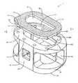
- FIG. 1Ashows a perspective view of an embodiment of the interbody spinal implant having a generally oval shape and roughened surface topography on the top surface;
- FIG. 1Bshows a top view of the first embodiment of the interbody spinal implant illustrated in FIG. 1A ;
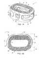
- FIG. 2shows a perspective view from the front of another embodiment of the interbody spinal implant according to the invention
- FIG. 3shows a perspective view from the rear of the embodiment of the interbody spinal implant illustrated in FIG. 2 ;
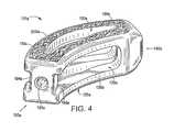
- FIG. 4shows a perspective view from the front of yet another embodiment of the interbody spinal implant according to the invention.
- FIG. 5shows a perspective view from the rear of the embodiment of the interbody spinal implant illustrated in FIG. 4 highlighting an alternative transverse aperture
- FIG. 6shows a perspective view of another embodiment of the interbody spinal implant having a generally oval shape and being especially well adapted for use in a cervical spine surgical procedure;
- FIG. 7shows a perspective view of an implant having a generally box shape
- FIG. 8Ashows an exploded view of a generally oval-shaped implant with an integration plate
- FIG. 8Bshows an exploded view of a generally oval-shaped implant with integration fixation and an integration plate
- FIG. 9shows an exploded view of a curved implant with an integration plate
- FIG. 10shows an exploded view of a posterior implant with an integration plate
- FIG. 11shows an exploded view of a lateral lumbar implant with an integration plate
- FIG. 12shows an exploded view of a generally oval-shaped anterior cervical implant with an integration plate
- FIG. 13Ashows a cut-away view of an integration plate
- FIG. 13Bshows a close-up of the cut-away portion illustrated in FIG. 13A with the post of the integration plate fit within a hole in the implant top surface;
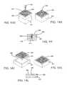
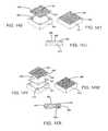
- FIG. 14Ashows an exploded view of a pin connection suitable for mounting an integration plate onto an implant
- FIG. 14Bshows the pin connection illustrated in FIG. 14A with the components assembled
- FIG. 14Cshows a cut-away view of the pin connection illustrated in FIGS. 14A and 14B ;
- FIG. 14Dshows an exploded view of a molded connection suitable for mounting an integration plate onto an implant
- FIG. 14Eshows the molded connection illustrated in FIG. 14D with the components assembled
- FIG. 14Fshows a cut-away view of the molded connection illustrated in FIGS. 14D and 14E ;
- FIG. 14Gshows an exploded view of a fastener connection suitable for mounting an integration plate onto an implant
- FIG. 14Hshows the fastener connection illustrated in FIG. 14G with the components assembled
- FIG. 14Ishows a cut-away view of the fastener connection illustrated in FIGS. 14G and 14H ;
- FIG. 14Jshows an exploded view of an undercut retention connection suitable for mounting an integration plate onto an implant
- FIG. 14Kshows the undercut retention connection illustrated in FIG. 14J with the components assembled
- FIG. 14Lshows a cut-away view of the undercut retention connection illustrated in FIGS. 14J and 14K ;
- FIG. 14Mshows an exploded view of adhesive-undercut connection suitable for mounting an integration plate onto an implant
- FIG. 14Nshows the adhesive-undercut connection illustrated in FIG. 14M with the components assembled
- FIG. 14Oshows a cut-away view of the adhesive-undercut connection illustrated in FIGS. 14M and 14N ;
- FIG. 14Pshows an exploded view of a press-fit connection suitable for mounting an integration plate onto an implant
- FIG. 14Qshows the press-fit connection illustrated in FIG. 14P with the components assembled
- FIG. 14Rshows a cut-away view of the press-fit connection illustrated in FIGS. 14P and 14Q ;
- FIG. 14Sshows an exploded view of a snap-fit connection suitable for mounting an integration plate onto an implant
- FIG. 14Tshows the snap-fit connection illustrated in FIG. 14S with the components assembled
- FIG. 14Ushows a cut-away view of the snap-fit connection illustrated in FIGS. 14S and 14T ;
- FIG. 14Vshows an exploded view of an internal molded connection suitable for mounting an integration plate onto an implant
- FIG. 14Wshows the internal molded connection illustrated in FIG. 14V with the components assembled
- FIG. 14Xshows a cut-away view of the internal molded connection illustrated in FIGS. 14V and 14W ;
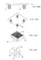
- FIG. 15Ashows an example of a roughened topography capable of being created by coating a material onto the surface of an implant
- FIG. 15Bshows a flat implant surface capable of receiving a coated roughened topography
- FIG. 15Cshows a cut-away view of the coated roughened topography illustrated in FIG. 15A ;
- FIG. 15Dshows an example of a roughened topography capable of being created by pressing a flexible foil onto the surface of an implant
- FIG. 15Eshows an exploded view of the flexible foil and implant surface
- FIG. 15Fshows an exploded side view of the flexible foil and implant illustrated in FIG. 15E ;
- FIG. 16Ashows a side view of the representation of an integration plate having posts with one groove for mating with a corresponding tongue structure in an implant hole;
- FIG. 16Bshows a bottom view of the representation illustrated in FIG. 16A ;
- FIG. 16Cshows an example of a tongue-and-groove connection suitable for mounting an integration plate onto an implant
- FIG. 16Dshows a close-up view of the tongue-and-groove connection illustrated in FIG. 16C ;
- FIG. 16Eshows a side view of a representation of an integration plate having posts with three grooves for mating with a corresponding tongue structure in an implant hole;
- FIG. 16Fshows a bottom view of the representation illustrated in FIG. 16E ;
- FIG. 16Gshows an example of a multiple tongue-and-groove connection suitable for mounting an integration plate onto an implant
- FIG. 16Hshows a close-up view of the multiple tongue-and-groove connection illustrated in FIG. 16G ;
- FIG. 16Ishows a side view of a representation of an integration plate having posts with a rounded tongue structure for mating with a corresponding groove in an implant hole;
- FIG. 16Jshows a bottom view of the representation illustrated in FIG. 16I ;
- FIG. 16Kshows an example of a rounded tongue-and-groove connection suitable for mounting an integration plate onto an implant
- FIG. 16Lshows a close-up view of the rounded tongue-and-groove connection illustrated in FIG. 16K ;
- FIG. 16Mshows a side view of a representation of an integration plate having posts with a diamond-shaped tongue structure for mating with a corresponding diamond-shaped groove in an implant hole;
- FIG. 16Nshows a bottom view of the representation illustrated in FIG. 16M ;
- FIG. 16Oshows an example of a diamond-shaped tongue-and-groove connection suitable for mounting an integration plate onto an implant
- FIG. 16Pshows a close-up view of the diamond-shaped tongue-and-groove connection illustrated in FIG. 16O ;
- FIG. 16Qshows a side view of a representation of an integration plate having posts with a threaded tongue structure for mating with a corresponding threaded groove in an implant hole;
- FIG. 16Rshows a bottom view of the representation illustrated in FIG. 16Q ;
- FIG. 16Sshows an example of a threaded tongue-and-groove connection suitable for mounting an integration plate onto an implant
- FIG. 16Tshows a close-up view of the threaded tongue-and-groove connection illustrated in FIG. 16S ;
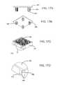
- FIG. 16Ushows a side view of a representation of an integration plate having posts with a plurality of a disc-shaped structures for mating with corresponding grooves in an implant hole;
- FIG. 16Vshows a bottom view of the representation illustrated in FIG. 16U ;
- FIG. 16Wshows an example of a disc-shaped tongue and groove connection suitable for mounting an integration plate onto an implant
- FIG. 16Xshows a close-up view of the disc-shaped tongue and groove connection illustrated in FIG. 16W ;
- FIG. 16Yshows a cut-away view of the disc-shaped tongue and groove connection illustrated in FIGS. 16W and 16X ;
- FIG. 17Ashows a side view of a representation of an integration plate having posts with vertically-oriented star-shaped tongue-and-groove structures for mating with corresponding vertically-oriented tongue-and-groove structures in an implant hole;
- FIG. 17Bshows a bottom view of the representation illustrated in FIG. 17A ;
- FIG. 17Cshows an example of a star-shaped tongue-and-groove connection suitable for mounting an integration plate onto an implant
- FIG. 17Dshows a close-up view of the star-shaped tongue-and-groove connection illustrated in FIG. 17C ;
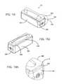
- FIG. 18Ashows an oval-shaped implant with a protruding anti-expulsion edge
- FIG. 18Bshows a close-up view of the protruding anti-expulsion edge of the implant illustrated in FIG. 18A ;
- FIG. 18Cshows a rectangular-shaped implant with a protruding anti-expulsion edge oriented toward the posterior portion
- FIG. 18Dshows a close-up view of the protruding anti-expulsion edge of the implant illustrated in FIG. 18C ;
- FIG. 18Eshows a perspective view of a curved-shaped implant with a protruding anti-expulsion edge oriented toward the posterior portion
- FIG. 18Fshows a close-up view of the protruding anti-expulsion edge of the implant perspective illustrated in FIG. 18E ;
- FIG. 18Gshows another perspective view of the implant illustrated in FIG. 18E ;
- FIG. 18Hshows a close-up view of the protruding anti-expulsion edge of the implant illustrated in FIG. 18G ;
- FIG. 18Ishows a perspective view of a rectangular-shaped implant with a protruding anti-expulsion edge oriented toward one of the lateral sides;
- FIG. 18Jshows another perspective view of the implant illustrated in FIG. 18I ;
- FIG. 18Kshows a close-up view of the protruding anti-expulsion edge of the implant illustrated in FIG. 18I ;
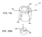
- FIG. 18Lshows a perspective view of a cervical implant with a protruding anti-expulsion edge
- FIG. 18Mshows a close-up view of the protruding anti-expulsion edge of the implant illustrated in FIG. 18L ;
- FIG. 19Ashows a cut-away view of an implant with an integration plate having a protruding anti-expulsion edge
- FIG. 19Bshows a smooth joint between the integration plate and the implant illustrated in FIG. 19A ;
- FIG. 20Ashows a side view of an integration plate having a protruding anti-expulsion edge
- FIG. 20Bshows a sharp edge configuration of the posterior edge of the integration plate illustrated in FIG. 20A ;
- FIG. 20Cshows a chamfered edge configuration of the posterior edge of an integration plate
- FIG. 20Dshows a radiused edge configuration of the posterior edge of an integration plate
- FIG. 21shows an example of an integration plate lordotic angle
- FIG. 22shows a example of an anti-expulsion edge angle.
- Certain embodiments of the inventionmay be especially suited for placement between adjacent human vertebral bodies.
- the implants of the inventionmay be used in procedures such as Anterior Lumbar Interbody Fusion (ALIF), Posterior Lumbar Interbody Fusion (PLIF), Transforaminal Lumbar Interbody Fusion (TLIF), and cervical fusion. Certain embodiments do not extend beyond the outer dimensions of the vertebral bodies.
- Interbody spinal implantsallow for improved seating over the apophyseal rim of the vertebral body. Still further, interbody spinal implants, as now taught, better utilize this vital surface area over which fusion may occur and may better bear the considerable biomechanical loads presented through the spinal column with minimal interference with other anatomical or neurological spinal structures. Even further, interbody spinal implants, according to certain aspects of the invention, allow for improved visualization of implant seating and fusion assessment. Interbody spinal implants, as now taught, may also facilitate osteointegration with the surrounding living bone.
- Anterior interbody spinal implants in accordance with certain aspects of the inventioncan be preferably made of a durable material such as stainless steel, stainless steel alloy, titanium, or titanium alloy, but can also be made of other durable materials such as, but not limited to, polymeric, ceramic, and composite materials.
- a durable materialsuch as stainless steel, stainless steel alloy, titanium, or titanium alloy
- other durable materialssuch as, but not limited to, polymeric, ceramic, and composite materials.
- certain embodiments of the inventionmay be comprised of a biocompatible, polymeric matrix reinforced with bioactive fillers, fibers, or both.
- Certain embodiments of the inventionmay be comprised of urethane dimethacrylate (DUDMA)/tri-ethylene glycol dimethacrylate (TEDGMA) blended resin and a plurality of fillers and fibers including bioactive fillers and E-glass fibers.
- Durable materialsmay also consist of any number of pure metals, metal alloys, or both.
- Titanium and its alloysare generally preferred for certain embodiments of the invention due to their acceptable, and desirable, strength and biocompatibility.
- certain embodiments of the present interbody spinal implantmay have improved structural integrity and may better resist fracture during implantation by impact. Interbody spinal implants, as now taught, may therefore be used as a distractor during implantation.
- FIG. 1shows a perspective view of a first embodiment of the interbody spinal implant 1 especially well adapted for use in an ALIF procedure.
- the interbody spinal implant 1includes a body having a top surface 10 , a bottom surface 20 , opposing lateral sides 30 , and opposing anterior 40 and posterior 50 portions.
- One or both of the top surface 10 and the bottom surface 20has a roughened topography 80 .
- the roughened topography 80is distinct from the teeth provided on the surfaces of some conventional devices.
- the interbody spinal implant 1is substantially hollow and has a generally oval-shaped transverse cross-sectional area with smooth, rounded, or both smooth and rounded lateral sides 30 and posterior-lateral corners 52 .
- a substantially hollow implant 1includes an implant 1 having at least about 33% of the interior volume of the implant 1 vacant.
- the implant 1includes at least one vertical aperture 60 that extends the entire height of the implant body.
- the vertical aperture 60may further define a transverse rim 100 having a greater posterior portion thickness 55 than an anterior portion thickness 45 .
- the opposing lateral sides 30 and the anterior portion 40have a rim thickness 45 of about 5 mm, while the posterior portion 50 has a rim thickness 55 of about 7 mm.
- the rim posterior portion thickness 55may allow for better stress sharing between the implant 1 and the adjacent vertebral endplates and helps to compensate for the weaker posterior endplate bone.
- the transverse rim 100has a generally large surface area and contacts the vertebral endplate. The transverse rim 100 may act to better distribute contact stresses upon the implant 1 , and hence minimize the risk of subsidence while maximizing contact with the apophyseal supportive bone.
- the transverse rim 100may have a substantially constant thickness (e.g., for the anterior portion thickness 45 to be substantially the same as the posterior portion thickness 55 ) or for the posterior portion 50 to have a rim thickness 55 less than that of the opposing lateral sides 30 and the anterior portion 40 .
- implant fixationmay depend, at least in part, on the attachment and proliferation of osteoblasts and like-functioning cells upon the implant surface. Still further, it appears that these cells attach more readily to relatively rough surfaces rather than smooth surfaces. In this manner, a surface may be bioactive due to its ability to facilitate cellular attachment and osteointegration.
- the surface roughened topography 80may better promote the osteointegration of the implant 1 .
- the surface roughened topography 80may also better grip the vertebral endplate surfaces and inhibit implant migration of the implant 1 upon placement and seating in a patient.
- the implant 1further includes the roughened topography 80 on at least a portion of its top 10 and bottom 20 surfaces for gripping adjacent bone and inhibiting migration of the implant 1 .
- FIG. 1shows roughened topography 80 on an embodiment of the implant 1 .
- the roughened topography 80may be obtained through a variety of techniques including, without limitation, chemical etching, shot peening, plasma etching, laser etching, or abrasive blasting (such as sand or grit blasting).
- the interbody spinal implant 1may be comprised of titanium, or a titanium alloy, having the surface roughened topography 80 .
- the surfaces of the implant 1are preferably bioactive.
- the roughened topography 80is obtained via the repetitive masking and chemical or electrochemical milling processes described in U.S. Pat. No. 5,258,098; U.S. Pat. No. 5,507,815; U.S. Pat. No. 5,922,029; and U.S. Pat. No. 6,193,762.
- Each of these patentsis incorporated in this document by reference.
- the surfaceis prepared through an etching process which utilizes the random application of a maskant and subsequent etching of the metallic substrate in areas unprotected by the maskant. This etching process is repeated a number of times as necessitated by the amount and nature of the irregularities required for any particular application.
- Control of the strength of the etchant material, the temperature at which the etching process takes place, and the time allotted for the etching processallow fine control over the resulting surface produced by the process.
- the number of repetitions of the etching processcan also be used to control the surface features.
- an etchant mixture of nitric acid (HNO 3 ) and hydrofluoric (HF) acidmay be repeatedly applied to a titanium surface to produce an average etch depth of about 0.53 mm.
- Interbody spinal implants 1in accordance with some preferred embodiments of the invention, may be comprised of titanium, or a titanium alloy, having an average surface roughness of about 100 ⁇ m. Surface roughness may be measured using a laser profilometer or other standard instrumentation.
- chemical modification of the titanium implant surfacescan be achieved using HF and a combination of hydrochloric acid and sulfuric acid (HCl/H 2 SO 4 ).
- HFhydrochloric acid and sulfuric acid
- the first exposureis to HF and the second is to HCl/H 2 SO 4 .
- Chemical acid etching alone of the titanium implant surfacehas the potential to greatly enhance osteointegration without adding particulate matter (e.g., hydroxyapatite) or embedding surface contaminants (e.g., grit particles).
- the implant 1may be shaped to reduce the risk of subsidence, and improve stability, by maximizing contact with the apophyseal rim of vertebral endplates. Embodiments may be provided in a variety of anatomical footprints having a medial-lateral width ranging from about 32 mm to about 44 mm.
- An interbody spinal implant 1generally does not require extensive supplemental or obstructive implant instrumentation to maintain the prepared disc space during implantation.
- the interbody spinal implant 1 and associated implantation methodsallow for larger-sized implants as compared with other size-limited interbody spinal implants known in the art. This advantage allows for greater medial-lateral width and correspondingly greater contact with the apophyseal rim.
- the implant 1may also include an anti-expulsion edge 8 as described in more detail below.
- the implant 1has an opening 90 in the anterior portion 40 .
- the posterior portion 50has a similarly shaped opening 90 .
- only the anterior portion 40has the opening 90 while the posterior portion 50 has an alternative opening 92 (which may have a size and shape different from the opening 90 ).
- the opening 90has a number of functions. One function is to facilitate manipulation of the implant 1 by the caretaker.
- the caretakermay insert a surgical tool into the opening 90 and, through the engagement between the surgical tool and the opening 90 , manipulate the implant 1 .
- the opening 90may be threaded to enhance the engagement.
- the implant 1may further include at least one transverse aperture 70 that extends the entire transverse length of the implant body.
- the at least one transverse aperture 70may provide improved visibility of the implant 1 during surgical procedures to ensure proper implant placement and seating, and may also improve post-operative assessment of implant fusion.
- the substantially hollow area defined by the implant 1may be filled with cancellous autograft bone, allograft bone, DBM, porous synthetic bone graft substitute, BMP, or combinations of these materials (collectively, bone graft materials), to facilitate the formation of a solid fusion column within the spine of a patient.
- Certain embodiments of the inventionare particularly suited for use during interbody spinal implant procedures (or vertebral body replacement procedures) and may act as a final distractor during implantation, thus minimizing the instrument load upon the surgeon.
- the spinemay first be exposed via an anterior approach and the center of the disc space identified.
- the disc spaceis then initially prepared for implant insertion by removing vertebral cartilage.
- Soft tissue and residual cartilagemay then also be removed from the vertebral endplates.
- Vertebral distractionmay be performed using trials of various-sized embodiments of the interbody spinal implant 1 .
- the determinatively sized interbody implant 1may then be inserted in the prepared disc space for final placement.
- the distraction procedure and final insertionmay also be performed under fluoroscopic guidance.
- the substantially hollow area within the implant bodymay optionally be filled, at least partially, with bone fusion-enabling materials such as, without limitation, cancellous autograft bone, allograft bone, DBM, porous synthetic bone graft substitute, BMP, or combinations of those materials.
- bone fusion-enabling materialmay be delivered to the interior of the interbody spinal implant 1 using a delivery device mated with the opening 90 in the anterior portion 40 of the implant 1 .
- the interbody spinal implant 1may be generally larger than those currently known in the art, and therefore have a correspondingly larger hollow area which may deliver larger volumes of fusion-enabling bone graft material.
- the bone graft materialmay be delivered such that it fills the full volume, or less than the full volume, of the implant interior and surrounding disc space appropriately.
- FIG. 1shows a perspective view of one embodiment of the invention, the interbody spinal implant 1 , which is especially well adapted for use in an ALIF procedure.
- Other embodiments of the inventionare better suited for PLIF, TLIF, or cervical fusion procedures.
- FIGS. 2 and 3show perspective views, from the front and rear, respectively, of an embodiment of an interbody spinal implant 101 especially well adapted for use in a PLIF procedure.
- the interbody spinal implant 101includes a body having a top surface 110 , a bottom surface 120 , opposing lateral sides 130 , and opposing anterior 140 and posterior 150 portions.
- One or both of the top surface 110 and the bottom surface 120has a roughened topography 180 for gripping adjacent bone and inhibiting migration of the implant 101 .
- the interbody spinal implant 101are substantially hollow and have a generally rectangular shape with smooth, rounded, or both smooth and rounded lateral sides and anterior-lateral corners.
- the anterior portion 140may have a tapered nose 142 to facilitate insertion of the implant 101 .
- the implant 101has chamfers 106 at the corners of its posterior portion 150 . The chamfers 106 prevent the implant 101 from catching upon insertion, risking potential damage such as severed nerves, while still permitting the implant 101 to have an anti-expulsion edge 108 .
- the implant 101includes at least one vertical aperture 160 that extends the entire height of the implant body.
- the vertical aperture 160further defines a transverse rim 200 .
- the size and shape of the vertical aperture 160are carefully chosen to achieve a preferable design tradeoff for the particular application envisioned for the implant 101 .
- the vertical aperture 160seeks to maximize the surface area of the top surface 110 and the bottom surface 120 available proximate the anterior 140 and posterior 150 portions while maximizing both radiographic visualization and access to the bone graft material toward the center of the top 110 and bottom 120 surfaces.
- the size and shape of the vertical aperture 160are predetermined by the application to which the implant 101 will be used.
- the width of the implant 101 between the two lateral sides 130is approximately 9 mm.
- the shape of the vertical aperture 160approximates, in cross section, that of an American football.
- the center of the vertical aperture 160which defines the maximum width of the vertical aperture 160 , is about 5 mm.
- the rim thickness 200 on either side of the vertical aperture 160 adjacent the center of the vertical aperture 160is about 2 mm.
- the vertical aperture 160tapers from its center to its ends along a longitudinal distance of about 7.75 mm (thus, the total length of the vertical aperture 160 is about 15.5 mm). This shape leaves intact much of the rim thickness 200 in the areas around the ends of the vertical aperture 160 . These areas may allow for better stress sharing between the implant 101 and the adjacent vertebral endplates. Thus, the transverse rim 200 has a generally large surface area and contacts the vertebral endplate.
- the implant 101has an opening 190 in the posterior portion 150 .
- the opening 190has a number of functions. One function is to facilitate manipulation of the implant 101 by the caretaker.
- the caretakermay insert a surgical tool into the opening 190 and, through the engagement between the surgical tool and the opening 190 , manipulate the implant 101 .
- the opening 190may be threaded to enhance the engagement.
- the implant 101may also have an Implant Holding Feature (IHF) 194 instead of or in addition to the opening 190 .
- IHFImplant Holding Feature
- the IHF 194is located proximate the opening 190 in the posterior portion 150 .
- the IHF 194is a U-shaped notch.
- the IHF 194has a number of functions, one of which is to facilitate manipulation of the implant 101 by the caretaker. Other functions of the opening 190 and the IHF 194 are to increase visibility of the implant 101 during surgical procedures and to enhance engagement between bone graft material and adjacent bone.
- the implant 101may further include at least one transverse aperture 170 .
- the size and shape of the transverse aperture 170are carefully chosen (and predetermined) to achieve a preferable design tradeoff for the particular application envisioned for the implant 101 .
- the transverse aperture 170should have minimal dimensions to maximize the strength and structural integrity of the implant 101 .
- the transverse aperture 70should have maximum dimensions to (a) improve the visibility of the implant 101 during surgical procedures to ensure proper implant placement and seating, and to improve post-operative assessment of implant fusion, and (b) to facilitate engagement between bone graft material and adjacent bone.
- the substantially hollow area defined by the implant 101may be filled with bone graft materials to facilitate the formation of a solid fusion column within the spine of a patient.
- the transverse aperture 170extends the entire transverse length of the implant body and nearly the entire height of the implant body. Thus, the size and shape of the transverse aperture 170 approach the maximum possible dimensions for the transverse aperture 170 .
- the transverse aperture 170may be broken into two, separate sections by an intermediate wall 172 .
- the section of the transverse aperture 170 proximate the IHF 194is substantially rectangular in shape; the other section of the transverse aperture 170 has the shape of a curved arch. Other shapes and dimensions are suitable for the transverse aperture 170 . In particular, all edges of the transverse aperture 170 may be rounded, smooth, or both.
- the intermediate wall 172may be made of the same material as the remainder of the implant 101 (e.g., metal), or it may be made of another material (e.g., PEEK) to form a composite implant 101 .
- the intermediate wall 172may offer one or more of several advantages, including reinforcement of the implant 101 and improved bone graft containment.
- FIGS. 2 and 3The embodiment of the invention illustrated in FIGS. 2 and 3 is especially well suited for a PLIF surgical procedure.
- TLIF surgeryis done through the posterior (rear) part of the spine and is essentially like an extended PLIF procedure.
- the TLIF procedurewas developed in response to some of the technical problems encountered with a PLIF procedure.
- the main difference between the two spine fusion proceduresis that the TLIF approach to the disc space is expanded by removing one entire facet joint; a PLIF procedure is usually done on both sides by only taking a portion of each of the paired facet joints.
- the anterior approachin most cases still provides the best visualization, most surface area for healing, and the best reduction of any of the approaches to the disc space.
- These advantagesmust be weighed, however, against the increased morbidity (e.g., unwanted aftereffects and postoperative discomfort) of a second incision.
- Probably the biggest determinate in how the disc space is approachedis the comfort level that the spine surgeon has with an anterior approach for the spine fusion surgery. Not all spine surgeons are comfortable with operating around the great vessels (aorta and vena cava) or have access to a skilled vascular surgeon to help them with the approach. Therefore, choosing one of the posterior approaches for the spine fusion surgery is often a more practical solution.
- FIGS. 4 and 5The embodiment of the invention illustrated in FIGS. 4 and 5 is especially well suited when the spine surgeon elects a TLIF procedure. Many of the features of the implant 101 a illustrated in FIGS. 4 and 5 are the same as those of the implant 101 illustrated in FIGS. 2 and 3 . Therefore, these features are given the same reference numbers, with the addition of the letter “a,” and are not described further.
- the implant 101 ahas a curved shape.
- the chamfers 106 and anti-expulsion edge 108 of the implant 101are replaced by curves or rounded edges for the implant 101 a .
- the TLIF procedureoften permits use of a larger implant 101 a which, in turn, may affect the size and shape of the predetermined vertical aperture 160 a.
- the substantially constant 9 mm width of the transverse rim 200 of the implant 101is replaced with a larger, curved transverse rim 200 a .
- the width of the transverse rim 200 ais 9 mm in the regions adjacent the anterior 140 a and posterior 150 a portions. That width gradually increases to 11 mm, however, near the center of the transverse rim 200 a .
- the additional real estate provided by the transverse rim 200 aallows the shape of the vertical aperture 160 a to change, in cross section, from approximating a football to approximating a boomerang.
- the center of the vertical aperture 160 awhich defines the maximum width of the vertical aperture 160 a , is increased (from 5 mm for the implant 101 ) to about 7 mm.
- the implant 101 amay also have a lordotic angle to facilitate alignment.
- the lateral side 130 a depicted at the top of the implant 101 ais preferably generally greater in height than the opposing lateral side 130 a . Therefore, the implant 101 a may better compensate for the generally less supportive bone found in certain regions of the vertebral endplate.
- the transverse aperture 170 aextends the entire transverse length of the implant body and nearly the entire height of the implant body.
- FIG. 5highlights an alternative transverse aperture 170 a .
- the transverse aperture 170 ais broken into two, separate sections by an intermediate wall 172 a .
- the dimensions of the transverse aperture 170 a shown in FIG. 5are much smaller than those for the transverse aperture 170 a shown in FIG. 4 .
- the two sections of the alternative transverse aperture 170 aare each illustrated as substantially rectangular in shape and extending nearly the entire height of the implant body; other sizes and shapes are possible for one or both sections of the alternative transverse aperture 170 a.
- the intermediate wall 172 amay be made of the same material as the remainder of the implant 101 a (e.g., metal), or it may be made of another material (e.g., PEEK) to form a composite implant 101 a . It is also possible to extend the intermediate wall 172 a , whether made of metal, PEEK, ultra-high molecular weight polyethylene (UHMWPE), or another material, to eliminate entirely the transverse aperture 170 a . Given the reinforcement function of the intermediate wall 172 a , the length of the vertical aperture 160 a can be extended (as shown in FIG. 5 ) beyond the top surface 110 a and into the anterior portion 140 a of the implant 101 a.
- UHMWPEultra-high molecular weight polyethylene
- the top surface 110 a of the implant 101 aneed not include the roughened topography 180 a . This difference permits the implant 101 a , at least for certain applications, to be made entirely of a non-metal material. Suitable materials of construction for the implant 101 a of such a design (which would not be a composite) include PEEK, hedrocel, UHMWPE, other radiolucent soft plastics, and additional materials as would be known town artisan.
- the discsare usually not very large.
- the space available for the nervesis also not that great, however, which means that even a small cervical disc herniation may impinge on the nerve and cause significant pain.
- the implant 201is generally smaller in size than the other implant embodiments.
- the lower mechanical load requirements imposed by the cervical applicationtypically render a composite implant unnecessary. Therefore, the implant 201 is generally made entirely of metal (e.g., titanium) and devoid of other materials (e.g., PEEK).
- the implant 201includes a body having a top surface 210 , a bottom surface 220 , opposing lateral sides 230 , and opposing anterior 240 and posterior 250 portions.
- One or both of the top surface 210 and the bottom surface 220has a roughened topography 280 for gripping adjacent bone and inhibiting migration of the implant 201 .
- the implant 201is substantially hollow and has a generally oval shape with smooth, rounded, or both smooth and rounded edges.
- the implant 201includes at least one vertical aperture 260 that extends the entire height of the implant body.
- the vertical aperture 260further defines a transverse rim 300 .
- the size and shape of the vertical aperture 260are carefully chosen to achieve a preferable design tradeoff for the particular application envisioned for the implant 201 .
- the vertical aperture 260seeks to maximize the surface area of the top surface 210 and the bottom surface 220 , to allow for better stress sharing between the implant 201 and the adjacent vertebral endplates, while maximizing access to the bone graft material provided within the implant 201 .
- the size and shape of the vertical aperture 260are predetermined by the application.
- the implant 201has an opening 290 in the posterior portion 250 .
- the opening 290has a number of functions. One function is to facilitate manipulation of the implant 201 by the caretaker.
- the caretakermay insert a surgical tool into the opening 290 and, through the engagement between the surgical tool and the opening 290 , manipulate the implant 201 .
- the opening 290may be threaded to enhance the engagement.
- the implant 201may further include at least one transverse aperture 270 .
- the size and shape of the transverse aperture 270are carefully chosen (and predetermined) to achieve a preferable design tradeoff for the particular application envisioned for the implant 201 .
- the transverse aperture 270may extend the entire transverse length of the implant body and nearly the entire height of the implant body.
- the size and shape of the transverse aperture 270approach the maximum possible dimensions for the transverse aperture 270 .
- the implant 201may be provided with a solid rear wall 242 .
- the rear wall 242extends the entire width of the implant body and nearly the entire height of the implant body. Thus, the rear wall 242 essentially closes the anterior portion 240 of the implant 201 .
- the rear wall 242may offer one or more of several advantages, including reinforcement of the implant 201 and improved bone graft containment. In the cervical application, it may be important to prevent bone graft material from entering the spinal canal.
- the implant 201may have a generally box shape which gives the implant 201 increased cortical bone coverage.
- the implant 201 shown in FIG. 7has a curved transverse rim 300 in the area of the anterior portion 240 .
- the shape of the posterior portion 250 of the implant 201is substantially flat, however, and the shape of the transverse rim 300 in the area of the posterior portion 250 is substantially square.
- the posterior portion 250provides a face that can receive impact from a tool, such as a surgical hammer, to force the implant 201 into position.
- the implant 201may also have a lordotic angle to facilitate alignment. As illustrated in FIGS. 6 and 7 , the anterior portion 240 is preferably generally greater in height than the posterior portion 250 . Therefore, the implant 201 may better compensate for the generally less supportive bone found in certain regions of the vertebral endplate. As an example, four degrees of lordosis may be built into the implant 201 to help restore balance to the spine.
- the implant 1 , 101 , 101 a , and 201are generally shaped (i.e., made wide) to maximize contact with the apophyseal rim of the vertebral endplates. They are designed to be impacted between the endplates, with fixation to the endplates created by an interference fit and annular tension.
- the implants 1 , 101 , 101 a , and 201are shaped and sized to spare the vertebral endplates and leave intact the hoop stress of the endplates.
- a wide range of sizesare possible to capture the apophyseal rim, along with a broad width of the peripheral rim, especially in the posterior region. It is expected that such designs will lead to reduced subsidence. As much as seven degrees of lordosis (or more) may be built into the implants 1 , 101 , 101 a , and 201 to help restore cervical balance.
- endplate-sparing spinal implant 1 , 101 , 101 a , and 201When endplate-sparing spinal implant 1 , 101 , 101 a , and 201 seats in the disc space against the apophyseal rim, it should still allow for deflection of the endplates like a diaphragm. This means that, regardless of the stiffness of the spinal implant 1 , 101 , 101 a , and 201 , the bone graft material inside the spinal implant 1 , 101 , 101 a , and 201 receives load, leading to healthy fusion. The vertical load in the human spine is transferred though the peripheral cortex of the vertebral bodies.
- the natural biomechanicsmay be better preserved than for conventional devices. If this is true, the adjacent vertebral bodies should be better preserved by the implant 1 , 101 , 101 a , and 201 , hence reducing the risk of adjacent segment issues.
- the dual-acid etched roughened topography 80 , 180 , 180 a , and 280 of the top surface 30 , 130 , 130 a , and 230 and the bottom surface 40 , 140 , 140 a , and 240 along with the broad surface area of contact with the end-plates,is expected to yield a high pull-out force in comparison to conventional designs.
- a pull-out strength of up to 3,000 ntmay be expected.
- the roughened topography 80 , 180 , 180 a , and 280creates a biological bond with the end-plates over time, which should enhance the quality of fusion to the bone.
- the in-growthstarts to happen much earlier than the bony fusion.
- the center of the implant 1 , 101 , 101 a , and 201remains open to receive bone graft material and enhance fusion. Therefore, it is possible that patients might be able to achieve a full activity level sooner than for conventional designs.
- the spinal implant 1 , 101 , 101 a , and 201 according to the inventionoffers several advantages relative to conventional devices.
- Such conventional devicesinclude, among others, ring-shaped cages made of allograft bone material, threaded titanium cages, and ring-shaped cages made of PEEK or carbon fiber.
- the implant 1 , 101 , 101 a , and 201includes an integration plate 82 , 182 , 182 a , and 282 , for example, as shown in FIG. 8A-FIG . 10 and FIG. 12 .
- a lateral implant 301 having a substantially rectangular shapemay include an integration plate 382 , for example, as shown in FIG. 11 .
- the lateral implant 301comprises the same general features as the implant 1 , 101 , 101 a , and 201 , including a top surface 310 , a bottom surface 320 , lateral sides 330 , opposing anterior 340 and posterior 350 portions, an opening 390 , as well as at least one vertical aperture 360 that extends the entire height of the implant body, and one or more transverse apertures 370 that extend the entire transverse length of the implant body.
- the integration plateshown in the drawings as component 82 ( FIG. 8A and FIG. 8B ), 182 ( FIG. 10 ), 182 a ( FIG. 9 ), 382 ( FIG. 11 ), and 282 ( FIG. 12 ), respectively, includes the roughened surface topography 80 , 180 , 180 a , 280 , and 380 , and is connectable to either or both of the top surface 10 , 110 , 110 a , 210 , and 310 or bottom surface 20 , 120 , 120 a , 220 , and 320 .
- the integration plate 82 , 182 , 182 a , 282 , and 382includes a top surface 81 , 181 , 181 a , 281 , and 381 ; a bottom surface 83 , 183 , 183 a , 283 , and 383 ; an anterior portion 41 , 141 , 141 a , 241 , and 341 ; a posterior portion 51 , 151 , 151 a , 251 , and 351 ; and at least one vertical aperture 61 , 161 , 161 a , 261 , and 361 .
- the anterior portion 41 , 141 , 141 a , 241 , and 341preferably aligns with the anterior portion 40 , 140 , 140 a , 240 , and 340 of the main body of the implant 1 , 101 , 101 a , 201 , and 301 , respectively, and the posterior portion 51 , 151 , 151 a , 251 , and 351 aligns with the posterior portion 50 , 150 , 150 a , 250 , and 350 of the main body of the implant 1 , 101 , 101 a , 201 , and 301 , respectively.
- the vertical aperture 61 , 161 , 161 a , 261 , and 361preferably aligns with the vertical aperture 60 , 160 , 160 a , 260 , and 360 of the main body of the implant 1 , 101 , 101 a , 201 , and 301 , respectively.
- the integration plate vertical aperture 61 , 161 , 161 a , 261 , and 361 and the body vertical aperture 60 , 160 , 160 a , 260 , and 360preferably comprise substantially the same shape.
- the top surface 81 , 181 , 181 a , 281 , and 381 of the integration plate 82 , 182 , 182 a , 282 , and 382preferably comprises the roughened topography 80 , 180 , 180 a , 280 , and 380 .
- the bottom surface 83 , 183 , 183 a , 283 , and 383 of the integration plate 82 , 182 , 182 a , 282 , and 382preferably comprises a reciprocal connector structure, such as a plurality of posts 84 , 184 , 184 a , 284 , and 384 that align with and insert into a corresponding connector structure such as a plurality of holes 12 , 112 , 112 a , 212 , and 312 on the top surface 10 , 110 , 110 a , 210 , and 310 and/or bottom surface 20 , 120 , 120 a , 220 , and 320 of the main body of the implant 1 , 101 , 101 a , 201 , and 301 , respectively, and thus facilitate the connection between the integration plate 82 , 182 , 182 a , 282 , and 382 and the main body of the implant 1 , 101 , 101 a , 201 ,
- integration plates 82 , 182 , 182 a , 282 , and 382 with different sizes, shapes, or featuresmay be used in connection with the implant 1 , 101 , 101 a , 201 , and 301 , for example, to accommodate attributes of the spine of the patient to which the implant 1 , 101 , 101 a , 201 , and 301 is to be implanted.
- these different sizes, shapes, and featuresare lordotic angles; anti-expulsion edges 8 , 108 , 108 a , 208 , and 308 ; and anti-expulsion angles as described throughout this specification.
- the implant 1 , 101 , 101 a , 201 , and 301is configured to receive the integration plate 82 , 182 , 182 a , 282 , and 382 , respectively.
- the top surface 10 , 110 , 110 a , 210 , and 310 and/or bottom surface 20 , 120 , 120 a , 220 , and 320 of the implant 1 , 101 , 101 a , 201 , and 301may be recessed, and comprise a plurality of holes 12 , 112 , 112 a , 212 , and 312 that mate with the plurality of posts 84 , 184 , 184 a , 284 , and 384 on the bottom surface 83 , 183 , 183 a , 283 , and 383 of the integration plate 82 , 182 , 182 a , 282 , and 382 .
- FIG. 8A and FIG. 8Bshow that the top surface 10 is recessed and comprises a plurality of holes 12 , but the recessed bottom surface 20 and its holes 12 are not shown.
- FIG. 9shows that the top surface 110 a is recessed and comprises a plurality of holes 112 a , but the recessed bottom surface 120 a and its holes 112 a are not shown.
- FIG. 10shows that the top surface 110 is recessed and comprises a plurality of holes 112 , but the recessed bottom surface 120 and its holes 112 are not shown.
- FIG. 11shows that the top surface 310 is recessed and comprises a plurality of holes 312 , but the recessed bottom surface 320 and its holes 312 are not shown.
- top surface 210is recessed and comprises a plurality of holes 212 , but the recessed bottom surface 220 and its holes 212 are not shown.
- the recessmay be at a depth D, and the recess depth D preferably is uniform throughout the top surface 10 , 110 , 110 a , 210 , and 310 and/or bottom surface 20 , 120 , 120 a , 220 , and 320 .
- the recess depth Dpreferably corresponds to a thickness T of the integration plate 82 , 182 , 182 a , 282 , and 382 .
- the depth D and thickness Tare the same so that once the integration plate 82 , 182 , 182 a , 282 , and 382 and body of the implant 1 , 101 , 101 a , 201 , and 301 , respectively, are placed together, the top surface 10 , 110 , 110 a , 210 , and 310 and/or bottom surface 20 , 120 , 120 a , 220 , and 320 of the implant 1 , 101 , 101 a , 201 , and 301 is substantially even, at least at the seam/junction between the integration plate 82 , 182 , 182 a , 282 , and 382 and the top surface 10 , 110 , 110 a , 210 , and 310 or bottom surface 20 , 210 , 120 a , 2
- the posterior portion 51 , 151 , 151 a , 251 , and 351 and the anterior portion 41 , 141 , 141 a , 241 , and 341 of the integration plate 82 , 182 , 182 a , 282 , and 382have different thicknesses such that the anterior portion 41 , 141 , 141 a , 241 , and 341 has a greater thickness than the thickness T of the posterior portion 51 , 151 , 151 a , 251 , and 351 .
- the anterior portion 41has a greater thickness T′ than the thickness T of the posterior portion 51 .
- the recess depth D, the thickness T, and the thickness T′may each independently be from about 0.1 mm to about 10 mm. In preferred aspects, the recess depth D, the thickness T, and the thickness T′ may each independently be from about 1 mm to about 5 mm.
- either the recess depth D, the thickness T, and the thickness T′may be selected from about 0.1 mm, about 0.25 mm, about 0.5 mm, about 0.75 mm, about 1 mm, about 1.25 mm, about 1.5 mm, about 1.75 mm, about 2 mm, about 2.25 mm, about 2.5 mm, about 2.75 mm, about 3 mm, about 3.25 mm, about 3.5 mm, about 3.75 mm, about 4 mm, about 4.25 mm, about 4.5 mm, about 4.75 mm, about 5 mm, 5.5 mm, about 6 mm, about 6.5 mm, about 7 mm, about 75 mm, or about 8 mm.
- Recessing the top surface 10 , 110 , 110 a , 210 , and 310 or bottom surface 20 , 120 , 120 a , 220 , and 320exposes a ridge 11 , 111 , 111 a , 211 , and 311 against which the anterior portion 41 , 141 , 141 a , 241 , and 341 , posterior portion 51 , 151 , 151 a , 251 , and 251 or lateral side of the integration plate 82 , 182 , 182 a , 282 , and 382 may be seated when brought together with the implant 1 , 101 , 101 a , 201 , and 301 .
- the integration plate 82 , 182 , 182 a , 282 , and 382may be used with an implant suitable for ALIF (e.g., implant 1 , integration plate 82 ), PLIF (e.g., implant 101 , integration plate 182 ), or TLIF fusion (e.g., implant 101 a , integration plate 182 a ); may be used with an implant suitable for cervical fusion (e.g., implant 201 , integration plate 282 ); and may be used with an implant suitable for lateral lumbar insertion (e.g., implant 301 , integration plate 382 ).
- ALIFe.g., implant 1 , integration plate 82
- PLIFe.g., implant 101 , integration plate 182
- TLIF fusione.g., implant 101 a , integration plate 182 a
- an implant suitable for cervical fusione.g., implant 201 , integration plate 282
- the integration plate 82 , 182 , 182 a , 282 , and 382is preferably metal, and may be used with a metal implant.
- the metal integration plate 82 , 182 , 182 a , 282 , and 382may also be used with a molded plastic or polymer implant, or a composite implant.
- the integration plate 82 , 182 , 182 a , 282 , and 382may also comprise a plastic, polymeric, or composite material.
- the reciprocal connectorsuch as the post 84 , 184 , 184 a , 284 , and 384 preferably is secured within the connector of the body such as the hole 12 , 112 , 112 a , 212 , and 312 to mediate the connection between the integration plate 82 , 182 , 182 a , 282 , and 382 and the implant 1 , 101 , 101 a , 201 , and 301 .
- the connectionshould be capable of withstanding significant loads and shear forces when implanted in the spine of the patient.
- connection between the post 84 , 184 , 184 a , 284 , and 384 and the hole 12 , 112 , 112 a , 212 , and 312may comprise a friction fit.
- FIG. 13Ashows a cut-away side view of the implant 1 having an integration plate 82 on the top 10 and bottom 20 portions, with the posts 84 inserted into the holes 12 .
- FIG. 13Bshows a close up view of the post 84 and hole 12 connection.
- the reciprocal connectorsuch as the post 84 , 184 , 184 a , 284 , and 384 and the connector of the body such as the hole 12 , 112 , 112 a , 212 , and 312 have additional compatible structures and features to further strengthen the connection between the integration plate 82 , 182 , 182 a , 282 , and 382 and the implant 1 , 101 , 101 a , 201 , and 301 .
- FIGS. 14-17Non-limiting examples of such structures and features are illustrated in FIGS. 14-17 .
- the structures and featuresmay be on either or both of the integration plate 82 , 182 , 182 a , 282 , and 382 and the main body of the implant 1 , 101 , 101 a , 201 , and 301 .
- the structuresinclude fasteners, compatibly shaped joints, compatibly shaped undercuts, and/or other suitable connectors having different shapes, sizes, and configurations.
- a fastenermay include a pin, screw, bolt, rod, anchor, snap, clasp, clip, clamp, or rivet.
- an adhesivemay be used to further strengthen any of the integration plate 82 , 182 , 182 a , 282 , and 382 and implant 1 , 101 , 101 a , 201 , and 301 connections described in this specification.
- An adhesivemay comprise a cement, glue, polymer, epoxy, solder, weld, or other suitable binding material.
- an integration plate 482(shown in the drawings as a box only for illustration purposes) having a roughened surface topography 480 may comprise one or more reciprocal connectors such as one or more posts 484 each having a bore 485 extending through a horizontal plane.
- the post 484is inserted into a connector such as a hole 412 through the implant 401 (also shown in the drawings as a box only for illustration purposes).
- a fastener 486which may be a pin 486 , is inserted through the bore 485 ( FIG. 14A ), thereby preventing the post 484 from being disengaged from the hole 412 ( FIG. 14B ).
- the pin 486is also threaded through a second bore 487 that passes through the walls of the implant 401 itself, although it is preferable that the implant 401 does not include a second bore 487 through its walls and that the bore 485 is accessible from the space inside of the implant 401 .
- components numbered in the four hundred seriesare shown for illustration purposes, and correspond to features of each implant 1 , 101 , 101 a , 201 , and 301 ; for example, post 484 is representative of post 84 , 184 , 184 a , 284 , and 384 .
- FIGS. 14D-Fshow another embodiment of the integration plate 482 comprising a plurality of bores 485 present on and having an opening accessible from the bottom surface 483 of the integration plate 482 .
- the bores 485mate with a plurality of fasteners 486 , which may comprise rods 486 ( FIG. 14D ) integral with or otherwise attached to the top surface 410 or bottom surface (not shown) of the implant 401 .
- the rods 486may be molded as upward-facing extensions of the top surface 410 ( FIG. 14F ).
- the rods 486may be snap-fit into the bores 485 through the opening ( FIG. 14F ), in which case the opening may be slightly smaller in width than the bores 485 and rods 486 , though still allowing the rods 486 to pass through the opening and into the bores 485 .
- the integration plate 482comprises one or more bores 485 in a vertical plane, extending through the integration plate 482 , through which a fastener 486 , which may be a screw or bolt 486 , may be inserted.
- the screw or bolt 486may extend into a hole 412 extending at least partially into the implant 401 , and the hole 412 and screw or bolt 486 preferably comprise compatible screw threads 415 ( FIG. 14I ). Tightening of the screw or bolt 486 secures the integration plate 482 in place on the implant 401 ( FIG. 14H ).
- the hole 412may not be present, and the screw or bolt 486 may be screwed directly into the plastic or polymeric material, with the screw threads tightly gripping the plastic or polymeric material to form the connection.
- the integration platemay have a roughened topography 480 .
- the bottom surface 483 of the integration plate 482may comprise undercuts in shapes that form a tight junction with compatible shapes on the implant 401 .
- the bottom surface 483may comprise a dovetail joint, or bevel, or taper that fits with a counterpart dovetail joint, bevel, or taper on the implant 401 ( FIG. 14L ).
- the shape of each of the integration plate 482 undercuts ( FIG. 14J ) and counterpart undercuts on the implant 401 ( FIG. 14L )are such that the connection forms a joint between the implant 401 and integration plate 482 , and that this joint is established and retained with a tight tolerance ( FIG. 14K ).
- the integration plate 482comprising a plurality of bores 485 present on and having an opening accessible from the bottom surface 483 of the integration plate 482 may mate with a plurality of fasteners 486 , which may comprise rod-shaped adhesives 486 , or which may comprise rods 486 coated or otherwise impregnated with an adhesive ( FIG. 14M ).
- a rod-shaped adhesive 486may comprise an hourglass-shaped cross section, with one side capable of being snap-fit into the bores 485 through the opening, and with the other side capable of being snap-fit into bores 487 in the top surface 410 of the implant 401 .
- the rod-shaped adhesive 486may bridge the implant 401 and integration plate 482 together as shown in FIG. 14O .
- the implant 401comprises rods 486 integral with or otherwise attached to the top surface 410 or bottom surface (not shown) of the implant 401 , for example, as illustrated in FIG. 14D , and these rods 486 may be coated with an adhesive that joins the rods 486 together with the sidewalls of the bores 485 in the integration plate 482 .
- An adhesivemay directly join the integration plate 482 and the implant 401 together.
- the adhesivemay be applied to the bottom surface 483 of the integration plate 482 or the top surface 410 of the implant 401 , and each part bridged together with the adhesive (not illustrated).
- the bottom surface 483 of the integration plate 482may include undercuts in shapes that form a tight junction with compatible shapes on the implant 401 .
- an adhesivemay be applied to undercuts and joints as shown in FIG. 14J to strengthen the connection between the integration plate 482 and the implant 401 .
- FIGS. 14P-Rshow an alternative embodiment of undercuts on the integration plate 482 that form a connection with corresponding cuts on the implant 401 , and an adhesive may be applied to strengthen this connection.
- the integration plate 482may be connected to the implant 401 with a snap-fit connection, for example, as shown in FIGS. 14S-U .
- the integration plate 482may comprise one or more bores 485 extending vertically through the integration plate 482 , through which a fastener 486 , which may be a rivet, snap or snap button 486 , may be inserted ( FIG. 14S ).
- the rivets 486 , snaps 486 , or snap buttons 486may be integral with or otherwise attached to the top surface 410 ( FIG. 14S ) or bottom surface (not shown) of the implant 401 .
- the rivets 486 , snaps 486 , or snap buttons 486may be molded as upward-facing extensions of the top surface 410 ( FIG.
- the rivets 486 , snaps 486 , or snap buttons 486comprise a head portion with a diameter slightly larger than and a shaft portion with a diameter slightly smaller than the diameter of the bores 485 .
- at least the head portion of the rivets 486 , snaps 486 , or snap buttons 486is fabricated of a material that allows the head portion to compress slightly and pass through the bores 485 when the integration plate 482 is pressed toward the implant 401 , after which the head portion re-expands such that the rivets 486 , snaps 486 , or snap buttons 486 cannot be disengaged from the bores 485 ( FIG. 14T ).
- an anchor plate 486enhances the connection between the posts 484 of the integration plate 482 and the holes 412 of the implant 401 , as shown in FIGS. 14V-14X .
- the top surface 410 of the implant 401may be molded in a shape or configuration into which an anchor plate 486 may be inserted ( FIG. 14X ), or the anchor plate 486 may otherwise be adhered to the implant 401 .
- the anchor plate 486may comprise one or more bores 485 through which the post 484 may pass through ( FIG. 14V ).
- the integration plate 482 , anchor plate 486 , and implant 401may be pressed together to form a tight junction that maintains the connection of the integration plate 482 to the implant 401 .
- an integration plate 82 , 182 , 182 a , 282 , and 382may be joined together with an implant 1 , 101 , 101 a , 201 , and 301 .
- One non-limiting objective of this approachis to provide a roughened topography 80 , 180 , 180 a , 280 , and 380 to the surface of the implant 1 , 101 , 101 a , 201 , and 301 .
- the roughened topography 80 , 180 , 180 a , 280 , and 380can be established on the integration plate 82 , 182 , 182 a , 282 , and 382 according to any suitable methodology, including those described or exemplified in this specification.
- the roughened topography 80 , 180 , 180 a , 280 , and 380may also be provided by coating the implant 1 , 101 , 101 a , 201 , and 301 or the integration plate 82 , 182 , 182 a , 282 , and 382 with a roughened topography material (e.g., FIGS. 15A-F ).
- a materialsuch as metal filings, shavings, or fine metal particles or powder, or fine plastic or polymeric particles may be laid onto the top surface 10 , 110 , 110 a , 210 , and 310 or bottom surface 20 , 120 , 120 a , 220 , and 320 of the implant 1 , 101 , 101 a , 201 , and 301 or onto the top surface 81 , 181 , 181 a , 281 , and 381 of the integration plate 82 , 182 , 182 a , 282 , and 382 according to any suitable method.
- an adhesivemay be used to affix the material to the implant 1 , 101 , 101 a , 201 , and 301 or integration plate 82 , 182 , 182 a , 282 , and 382 .
- Plastic or polymeric materialsmay be spray-coated, airlaid, or melt-blown onto the implant 1 , 101 , 101 a , 201 , and 301 or integration plate 82 , 182 , 182 a , 282 , and 382 .
- the materialsmay be adhered directly, for example, by at least partially melting the particles such that they fuse to the desired surface when they cool.
- Metal materialsmay be cold sprayed or thermal sprayed onto the implant 1 , 101 , 101 a , 201 , and 301 or integration plate 82 , 182 , 182 a , 282 , and 382 according to any suitable technique.
- FIGS. 15A-Cshow a non-limiting embodiment of a roughened topography 480 coated onto the top surface 410 of the implant 401 (shown in the drawings as a box only for illustration purposes).
- the roughened topography 480may also be coated onto the bottom surface of the implant 401 (not shown).
- the roughened topography 480may be coated onto the top surface 481 of the integration plate 482 (not shown).
- a backing 479 comprising a roughened topography 480may be laid onto the top surface 410 of the implant 401 as shown in FIGS. 15D-F .
- the backing 479may comprise a foil, mesh, screen, or other suitable material, preferably comprising a metal, that is sufficiently flexible such that it may conform to the shapes and contours of the top surface 410 of the implant 401 ( FIG. 15E and FIG. 15F ).
- the backing 479may be laid onto the top surface 481 of the integration plate 482 (not shown).
- An adhesivemay be used to join the backing 479 to the top surface 410 of the implant 401 or top surface 481 of the integration plate 482 .
- the backing 479may be soldered, melted, or welded to the top surface 410 of the implant 401 or top surface 481 of the integration plate 482 .
- a preferred connection between the integration plate 82 , 182 , 182 a , 282 , and 382 and the implant 1 , 101 , 101 a , 201 , and 301includes the post 84 , 184 , 184 a , 284 , and 384 and hole 12 , 112 , 112 a , 212 , and 312 connection, without additional fasteners required to maintain this connection, for example, through a friction fit.
- the post 84 , 184 , 184 a , 284 , and 384 and hole 12 , 112 , 112 a , 212 , and 312include different interlocking joints to strengthen the connection between them. These interlocking joints preferably include different configurations of a basic tongue-and-groove joint, for example, as shown in FIGS. 16 and 17 .
- an integration plate 482(shown in the drawings as a box only for illustration purposes) having a roughened surface topography 480 may comprise one or more posts 484 ( FIG. 16A ), each comprising a groove 488 ( FIG. 16A and FIG. 16B ).
- the posts 484may include more than one groove 488 , including two, three, four, five, six, seven, eight or more grooves 488 .
- FIG. 16E and FIG. 16Fshow a non-limiting example of a post 484 with three groves 488 .
- each groove 488preferably mates with a corresponding tongue 489 in the hole 412 of the implant 401 .
- each hole 412may include one tongue 489 that forms a connection with one groove 488 in the post 484 .
- the holes 412may include more than one tongue 489 , including two, three, four, five, six, seven, eight or more tongues 489 .
- FIGS. 16G and 16Hshow a non-limiting example of each hole 412 including three tongues 489 .
- the post 484When the integration plate 482 is pressed together with the implant 401 (shown in the drawings as a box only for illustration purposes), the post 484 is inserted into its corresponding hole 412 , and each tongue 489 is inserted into its corresponding groove 488 .
- the material used to fabricate the tongue 489is sufficiently flexible to allow the wider portions of the post 484 that flank each groove 488 to pass over the tongue 489 so that the tongue 489 can fit within its groove 488 , yet is sufficiently rigid to prevent disengagement of the tongue 489 from the groove 488 once the integration plate 482 and implant 481 are together.
- FIGS. 16I-Xshow examples of a post 484 and hole 412 connection in which the post 484 comprises one or more tongues 489 that fit within one or more grooves 488 in the sidewalls of the hole 412 .
- the tongue 489may comprise a round shape ( FIGS. 16I and 16J ), and may thus mate with a groove 488 having a reciprocal round shape ( FIGS. 16K and 16L ).
- the tongue 489may comprise a triangular shape ( FIGS. 16E and 16F ), and may thus mate with a groove 488 having a reciprocal triangular shape ( FIGS. 16G and 16H ).
- the tongue 489may comprise a diamond shape ( FIGS. 16M and 16N ), and may thus mate with a groove 488 having a reciprocal diamond shape ( FIGS. 16O and 16P ).
- the tongue 489may comprise a threaded shape ( FIGS.
- FIGS. 16Q and 16Rmay thus mate with a groove 488 having a reciprocal threaded shape ( FIGS. 16S and 16T ).
- the tongue 489may comprise a disc shape ( FIGS. 16U and 16V ), and may thus mate with a groove 488 having a reciprocal disc shape ( FIGS. 16W and 16X ). A cross-section of such a configuration is shown in FIG. 16Y .
- Each holemay include one groove 488 that forms a connection with one tongue 489 on the post 484 .
- the holes 412may include more than one groove 488 , including two, three, four, five, six, seven, eight or more grooves 488 .
- the post 484may include more than one tongue 489 , including two, three, four, five, six, seven, eight or more tongues 489 .
- the post 484is inserted into its corresponding hole 412 , and the tongue 489 is inserted into its corresponding groove 488 .
- the material out of which the tongue 489 is fabricatedis sufficiently flexible to allow the tongue 489 to pass over the wider portions of the hole 412 that flank each groove 488 so that the tongue 489 can fit within its groove 488 , yet is sufficiently rigid to prevent disengagement of the tongue 489 from the groove 488 once the integration plate 482 and implant 481 are together.
- the tongue 489 and groove 488may comprise any suitable shape, and preferably, each has a shape compatible with its counterpart. The shape may be regular or irregular. Each of the tongue 489 and groove 488 may comprise a substantially round, triangular, diamond, square, dovetail, or polygonal shape. Optionally, an adhesive may be used to further strengthen the connection between the tongue 489 and the groove 488 .
- FIGS. 16A-Yshow non-limiting examples of a tongue 489 and groove 488 connection in which each tongue 489 and groove 488 are oriented in a horizontal plane.
- the tongue 489 and groove 488may be oriented in a vertical plane.
- an integration plate 482may comprise one or more posts 484 , with each post 484 comprising one or more vertically oriented tongues 489 .
- Each vertically oriented tongue 489preferably mates with a corresponding vertically oriented groove 488 in the hole 412 .
- the posts 484may, for example, have a star shape ( FIGS.
- the holes 412may have a reciprocal star shape ( FIGS. 17C and 17D ) with the edges of the stars forming reciprocal grooves 488 and tongues 489 .
- each post 484is inserted into its corresponding hole 412 , and the vertically oriented tongue 489 is inserted into its corresponding vertically oriented groove 488 .
- Each post 484including its vertically oriented tongues 489 , preferably has a wider diameter than the corresponding hole 412 , including the vertically oriented grooves 488 , such that a tight friction fit is established and maintained between the post 484 and the hole 412 .
- an adhesivemay be used to further strengthen the connection.
- the disc spacemay be accessed using a standard mini open retroperitoneal laparotomy approach.
- the center of the disc spaceis located by AP fluoroscopy taking care to make sure the pedicles are equidistant from the spinous process.
- the disc spaceis then incised by making a window in the annulus for insertion of certain embodiments of the spinal implant 1 (a 32 or 36 mm window in the annulus is typically suitable for insertion).
- the process according to the inventionminimizes, if it does not eliminate, the cutting of bone.
- the endplatesare cleaned of all cartilage with a curette, however, and a size-specific rasp (or broach) may then be used.
- a rasppreferably substantially minimizes or eliminates removal of bone, thus substantially minimizing or eliminating impact to the natural anatomical arch, or concavity, of the vertebral endplate while preserving much of the apophyseal rim.
- Preservation of the anatomical concavityis particularly advantageous in maintaining biomechanical integrity of the spine. For example, in a healthy spine, the transfer of compressive loads from the vertebrae to the spinal disc is achieved via hoop stresses acting upon the natural arch of the endplate. The distribution of forces, and resultant hoop stress, along the natural arch allows the relatively thin shell of subchondral bone to transfer large amounts of load.
- the vertebral endplate natural archmay be significantly removed due to excessive surface preparation for implant placement and seating. This is especially common where the implant is to be seated near the center of the vertebral endplate or the implant is of relatively small medial-lateral width. Breaching the vertebral endplate natural arch disrupts the biomechanical integrity of the vertebral endplate such that shear stress, rather than hoop stress, acts upon the endplate surface. This redistribution of stresses may result in subsidence of the implant into the vertebral body.
- interbody spinal implant 1 , 101 , 101 a , 201 , and 301include smooth, rounded, and highly radiused posterior portions and lateral sides which may minimize extraneous bone removal for endplate preparation and reduce localized stress concentrations.
- interbody surgical implant 1 , 101 , 101 a , 201 , and 301 and methods of using itare particularly useful in preserving the natural arch of the vertebral endplate and minimizing the chance of implant subsidence.
- endplatesare spared during the process of inserting the spinal implant 1 , 101 , 101 a , 201 , and 301 .
- Spared endplatesallow the transfer of axial stress to the apophasis. Endplate flexion allows the bone graft placed in the interior of the spinal implant 1 to accept and share stress transmitted from the endplates.
- spared endplatesminimize the concern that BMP might erode the cancellous bone.
- Interbody spinal implant 1is durable and can be impacted between the endplates with standard instrumentation. Therefore, certain embodiments of the invention may be used as the final distractor during implantation. In this manner, the disc space may be under-distracted (e.g., distracted to some height less than the height of the interbody spinal implant 1 ) to facilitate press-fit implantation. Further, certain embodiments of the current invention having a smooth and rounded posterior portion (and lateral sides) may facilitate easier insertion into the disc space. Still further, those embodiments having a surface roughened topography 80 may lessen the risk of excessive bone removal during distraction as compared to implants having teeth, ridges, or threads currently known in the art even in view of a press-fit surgical distraction method.
- the interbody surgical implant 1may provide secure seating and prove difficult to remove.
- certain embodiments of the interbody spinal implant 1 , 101 , 101 a , 201 , and 301may maintain a position between the vertebral endplates due, at least in part, to resultant annular tension attributable to press-fit surgical implantation and, post-operatively, improved osteointegration at the top surface 10 , 110 , 110 a , 210 , and 310 ; the bottom surface 20 , 120 , 120 a , 220 , and 320 ; or both surfaces.
- Implant systems and methodstension the vertebral annulus via distraction. These embodiments and methods may also restore spinal lordosis, thus improving sagittal and coronal alignment.
- Implant systems currently known in the artrequire additional instrumentation, such as distraction plugs, to tension the annulus. These distraction plugs require further tertiary instrumentation, however, to maintain the lordotic correction during actual spinal implant insertion. If tertiary instrumentation is not used, then some amount of lordotic correction may be lost upon distraction plug removal.
- Interbody spinal implant 1is particularly advantageous in improving spinal lordosis without the need for tertiary instrumentation, thus reducing the instrument load upon the surgeon. This reduced instrument load may further decrease the complexity, and required steps, of the implantation procedure.
- spinal implant 1 , 101 , 101 a , 201 , and 301may also reduce deformities (such as isthmic spondylolythesis) caused by distraction implant methods.
- Traditional implant systemsrequire secondary or additional instrumentation to maintain the relative position of the vertebrae or distract collapsed disc spaces.
- interbody spinal implant 1 , 101 , 101 a , 201 , and 301may be used as the final distractor and thus maintain the relative position of the vertebrae without the need for secondary instrumentation.
- Certain embodimentscollectively comprise a family of implants, each having a common design philosophy. These implants and the associated surgical technique have been designed to address at least the ten, separate challenges associated with the current generation of traditional anterior spinal fusion devices listed above in the Background section of this document.
- Embodiments of the inventionallow end-plate preparation with custom-designed rasps. These rasps preferably have a geometry matched with the geometry of the implant.
- the raspsconveniently remove cartilage from the endplates and remove minimal bone, only in the postero-lateral regions of the vertebral end-plates. It has been reported in the literature that the end-plate is the strongest in postero-lateral regions.
- embodiments of the inventionfirst adequately distract the disc space by inserting (through impaction) and removing sequentially larger sizes of very smooth distractors, which have been size matched with the size of the available implant 1 . Once adequate distraction is achieved, the surgeon prepares the end-plate with a rasp. There is no secondary instrumentation required to keep the disc space distracted while the implant 1 , 101 , 101 a , 201 , and 301 is inserted, as the implant 1 , 101 , 101 a , 201 , and 301 has sufficient mechanical strength that it is impacted into the disc space.
- the height of the implant 1 , 101 , 101 a , 201 , and 301is preferably about 1 mm greater than the height of the rasp used for end-plate preparation, to create some additional tension in the annulus by implantation, which creates a stable implant construct in the disc space.
- the implant geometryhas features which allow it to be implanted via any one of an anterior, antero-lateral, or lateral approach, providing tremendous intra-operative flexibility of options.
- the implant 1 , 101 , 101 a , 201 , and 301is designed such that all the impact loads are applied only to the titanium part of the construct. Thus, the implant 1 , 101 , 101 a , 201 , and 301 has adequate strength to allow impact.
- the sides of the implant 1 , 101 , 101 a , 201 , and 301have smooth surfaces to allow for easy implantation and, specifically, to prevent binding of the implant 1 , 101 , 101 a , 201 , and 301 to soft tissues during implantation.
- the inventionencompasses a number of different implant 1 , 101 , 101 a , 201 , and 301 configurations, including a one-piece, titanium-only implant and a composite implant formed of top and bottom plates (components) made out of titanium.
- the surfaces exposed to the vertebral bodyare dual acid etched to allow for bony in-growth over time, and to provide resistance against expulsion.
- the top and bottom titanium platesare assembled together with the implant body that is injection molded with PEEK.
- the net resultis a composite implant that has engineered stiffness for its clinical application.
- the axial loadis borne by the PEEK component of the construct.
- an intact vertebral end-platedeflects like a diaphragm under axial compressive loads generated due to physiologic activities. If a spinal fusion implant is inserted in the prepared disc space via a procedure which does not destroy the end-plates, and if the implant contacts the end-plates only peripherally, the central dome of the end-plates can still deflect under physiologic loads. This deflection of the dome can pressurize the bone graft material packed inside the spinal implant, hence allowing it to heal naturally.
- the implant 1 , 101 , 101 a , 201 , and 301 designed according to certain embodimentsallows the vertebral end-plate to deflect and allows healing of the bone graft into fusion.
- the implant 1 , 101 , 101 a , 201 , and 301is configured to resist movement after being seated in the joint space of the spine.
- the implant 1 , 101 , 101 a , 201 , and 301may comprise one or more anti-expulsion edges 8 , 108 , 108 a , 208 , and 308 that tend to “dig” into the end-plates slightly and help to resist expulsion ( FIGS. 18A-18M ).
- the anti-expulsion edges 8 , 108 , 108 a , 208 , and 308may be present on the top surface 10 , 110 , 110 a , 210 , and 310 ; the bottom surface 20 , 120 , 120 a , 220 , and 320 ; or both surfaces of the implant 1 , 101 , 101 a , 201 , and 301 .
- FIG. 18Ashows an anti-expulsion edge 8 on the top surface 10 and bottom surface 20 of the anterior face 40 of the implant 1 .
- Each anti-expulsion edge 8protrudes above the plane of the top surface 10 and bottom surface 20 , with the amount of protrusion increasing toward the anterior face 40 and the highest protrusion height P at the anterior-most edge of the top surface 10 or bottom surface 20 .
- the protruding anti-expulsion edge 8exposes a protruding surface 9 .
- An anti-expulsion edge 8 , 108 , 108 a , 208 , and 308may be oriented toward the anterior portion 40 , 140 , 140 a , 240 , and 340 , or the posterior portion 50 , 150 , 150 a , 250 , and 350 , or either of the opposing lateral sides 30 , 130 , 130 a , 230 , and 330 .
- the orientation of the anti-expulsion edge 8 , 108 , 108 a , 208 , and 308may depend on the intended orientation of the implant 1 , 101 , 101 a , 201 , and 301 when it has been implanted between vertebrae in the patient.
- FIGS. 18C-18Hshow different perspective views of different embodiments of the implant 101 and 101 a , with the amount of protrusion increasing toward the posterior face 150 and 150 a and the highest protrusion height P at the posterior-most edge of the top surface 110 and 110 a or bottom surface 120 and 120 a .
- the protruding anti-expulsion edge 108 and 108 aexposes a protruding surface 109 and 109 a .
- FIGS. 18I-18Kshow different perspective views of an embodiment of the implant 301 , with the amount of protrusion increasing toward one of the opposing lateral sides 330 and the highest protrusion height P at the most lateral edge of the top surface 310 or bottom surface 320 .
- the protruding anti-expulsion edge 308exposes a protruding surface 309 .
- FIGS. 18L and 18Mshow different perspective views of an embodiment of the implant 201 , with the amount of protrusion increasing toward the anterior portion 240 and the highest protrusion height P at the anterior-most edge of the top surface 210 or bottom surface 220 .
- the protruding anti-expulsion edge 208exposes a protruding surface 209 .
- the integration plate 82 , 182 , 182 a , 282 , and 382establishes the anti-expulsion edge 8 , 108 , 108 a , 208 , and 308 for either or both of the top surface 10 , 110 , 110 a , 210 , and 310 and bottom surface 20 , 120 , 120 a , 220 , and 320 of the implant 1 , 101 , 101 a , 201 , and 301 .
- Different integration plates 82 , 182 , 182 a , 282 , and 382may be used to establish a range of highest protrusion heights P.
- FIG. 19Ashows a cross-section of the implant 1 with an integration plate 82 having a protruding anti-expulsion edge 8
- FIG. 19Bshows a close-up of the joint of the integration plate 82 and the top surface 10 of the implant 1 .
- the posterior portion 51 of the integration plate 82may comprise different edge features.
- FIGS. 20A-Dshow non-limiting examples of possible configurations of the posterior portion 51 of the integration plate 82 , with FIGS. 20B-D showing an enlarged view of the posterior portion 51 as encircled in FIG. 20A .
- the posterior portion 51may have a substantially straight edge as shown in FIG. 20A and FIG. 20B , such that the edge of the posterior portion 51 aligns with a corresponding straight edge in the posterior portion 50 of the implant 1 .
- the posterior portion 51may have a substantially straight edge, and include a beveled edge or chamfer 51 C as shown in FIG. 20C .
- the posterior portion 51may have a generally blunt nosed profile, including a generally rounded profile 51 D as shown in FIG. 20D .
- the implant 1 , 101 , 101 a , 201 , and 301may comprise a lordotic angle L, e.g., may be wedge-shaped to facilitate sagittal alignment.
- the anterior portion 40 , 140 , 140 a , 240 , and 340 of the implant 1 , 101 , 101 a , 201 , and 301may comprise a height that is larger than the height of the posterior portion 50 , 150 , 150 a , 250 , and 350 .
- the lordotic angle Lmay be established by the implant 1 , 101 , 101 a , 201 , and 301 itself, or may be established by the integration plate 82 , 182 , 182 a , 282 , and 382 when combined with the implant 1 , 101 , 101 a , 201 , and 301 .
- the lordotic angle L of the implant 1preferably closely approximates, or otherwise is substantially the same as, the angle of lordosis of the spine of the patient where the implant 1 , 101 , 101 a , 201 , and 301 will be implanted.
- the integration plate 82 , 182 , 182 a , 282 , and 382increases the lordotic angle L by about 3% to about 5%, measured according to the angle of lordosis of a particular patient's spine. For example, as shown in FIG.
- the anti-expulsion edge 8protrudes to a height sufficient to increase the overall height H of the anterior portion 40 of the implant 1 such that implant 1 has a lordotic angle L that is about 3% to about 5% greater than the patient's angle of lordosis.
- the implant 1 , 101 , 101 a , 201 , and 301may have a lordotic angle L about 3%, about 3.3%, about 3.5%, about 3.7%, about 4%, about 4.3%, about 4.5%, about 4.7%, or about 5% greater than the patient's angle of lordosis, though percentages greater than 5% or lesser 3% are possible.
- the increase of about 3% to about 5%preferably results from the combination of the protruding height of the integration plate 82 , 182 , 182 a , 282 , and 382 on the top portion 10 , 110 , 110 a , 210 , and 310 and bottom portion 20 , 120 , 120 a , 220 , and 320 of the implant 1 , 101 , 101 a , 201 , and 301 .
- the expulsion-resistant edge 8 , 108 , 108 a , 208 , and 308may comprise an anti-expulsion edge angle E, for example, as shown in FIG. 22 with respect to the implant 1 .
- the anti-expulsion edge angle Emay be from about 80 degrees to about 100 degrees.
- the anti-expulsion edge angle Emay be measured by taking into account the lordosis angle L of the implant 1 , 101 , 101 a , 201 , and 301 .
- the anti-expulsion edge angle Eis measured by subtracting half of the lordotic angle L from 90 degrees.
- the anti-expulsion edge angle Eis 84 degrees (90 ⁇ (12 ⁇ 0.5)).
- the anti-expulsion edge angle Emay be about 80 degrees, about 81 degrees, about 82 degrees, about 83 degrees, about 84 degrees, about 85 degrees, about 86 degrees, about 86.5 degrees, about 87 degrees, about 88 degrees, or about 89 degrees.
- the top and bottom surfaces of the implantmay be made out of titanium and are dual acid etched.
- the dual acid etching processcreates a highly roughened texture on these surfaces, which generates tremendous resistance to expulsion.
- the width of these dual acid etched surfacesis very broad and creates a large area of contact with the vertebral end-plates, further increasing the resistance to expulsion.
- the implant 1has a large foot-print, and offers several sizes. Because there is no secondary instrument required to maintain distraction during implantation, all the medial-lateral (ML) exposure is available as implantable ML width of the implant. This feature allows the implant to contact the vertebral end-plates at the peripheral apophyseal rim, where the end-plates are the strongest and least likely to subside.
- MLmedial-lateral
- the implant constructhas an engineered stiffness to minimize the stiffness mismatch with the vertebral body which it contacts.
- the implant 1has a large foot-print.
- titaniumprovides high strength for a small volume.
- the large foot-print along with the engineered use of titaniumallows for a large volume of bone graft to be placed inside the implant.
- an intact vertebral end-platedeflects like a diaphragm under axial compressive loads generated due to physiologic activities. If a spinal fusion implant is inserted in the prepared disc space via a procedure which does not destroy the end-plate, and if the implant contacts the end-plates only peripherally, the central dome of the end-plates can still deflect under physiologic loads. This deflection of the dome can pressurize the bone graft material packed inside the spinal implant, hence allowing it to heal naturally.
- the implant 1according to certain embodiments of the invention allows the vertebral end-plate to deflect and facilitates healing of the bone graft into fusion.
- the top and bottom surfaces of the implant 1are made of titanium and are dual acid etched.
- the dual acid etched surface treatment of titaniumallows in-growth of bone to the surfaces.
- the implant 1is designed to incorporate with the vertebral bone over time. It may be that the in-growth happens sooner than fusion. If so, there may be an opportunity for the patients treated with the implant 1 to return to normal activity levels sooner than currently recommended by standards of care.
- the titanium-only embodiment of the inventionhas been designed with large windows to allow for radiographic evaluation of fusion, both through AP and lateral X-rays.
- a composite implantminimizes the volume of titanium, and localizes it to the top and bottom surfaces.
- the rest of the implantis made of PEEK which is radiolucent and allows for free radiographic visualization.
Landscapes
- Health & Medical Sciences (AREA)
- Engineering & Computer Science (AREA)
- Biomedical Technology (AREA)
- Neurology (AREA)
- Orthopedic Medicine & Surgery (AREA)
- Cardiology (AREA)
- Oral & Maxillofacial Surgery (AREA)
- Transplantation (AREA)
- Heart & Thoracic Surgery (AREA)
- Vascular Medicine (AREA)
- Life Sciences & Earth Sciences (AREA)
- Animal Behavior & Ethology (AREA)
- General Health & Medical Sciences (AREA)
- Public Health (AREA)
- Veterinary Medicine (AREA)
- Prostheses (AREA)
Abstract
Description
Claims (20)
Priority Applications (4)
| Application Number | Priority Date | Filing Date | Title |
|---|---|---|---|
| US13/484,504US8562684B2 (en) | 2005-05-06 | 2012-05-31 | Endplate-preserving spinal implant with an integration plate having a roughened surface topography |
| PCT/US2013/043085WO2013181234A1 (en) | 2012-05-31 | 2013-05-29 | Endplate-preserving spinal implant with an integration plate having a roughened surface topography |
| US14/040,799US20140031942A1 (en) | 2005-05-06 | 2013-09-30 | Endplate-preserving spinal implant having a roughened surface topography |
| US14/063,031US8992622B2 (en) | 2005-05-06 | 2013-10-25 | Interbody spinal implant having a roughened surface topography |
Applications Claiming Priority (3)
| Application Number | Priority Date | Filing Date | Title |
|---|---|---|---|
| US11/123,359US7662186B2 (en) | 2005-05-06 | 2005-05-06 | Anterior interbody spinal implant |
| US12/151,198US8262737B2 (en) | 2005-05-06 | 2008-05-05 | Composite interbody spinal implant having openings of predetermined size and shape |
| US13/484,504US8562684B2 (en) | 2005-05-06 | 2012-05-31 | Endplate-preserving spinal implant with an integration plate having a roughened surface topography |
Related Parent Applications (1)
| Application Number | Title | Priority Date | Filing Date |
|---|---|---|---|
| US12/151,198Continuation-In-PartUS8262737B2 (en) | 2005-05-06 | 2008-05-05 | Composite interbody spinal implant having openings of predetermined size and shape |
Related Child Applications (1)
| Application Number | Title | Priority Date | Filing Date |
|---|---|---|---|
| US14/040,799ContinuationUS20140031942A1 (en) | 2005-05-06 | 2013-09-30 | Endplate-preserving spinal implant having a roughened surface topography |
Publications (2)
| Publication Number | Publication Date |
|---|---|
| US20120239152A1 US20120239152A1 (en) | 2012-09-20 |
| US8562684B2true US8562684B2 (en) | 2013-10-22 |
Family
ID=46829095
Family Applications (2)
| Application Number | Title | Priority Date | Filing Date |
|---|---|---|---|
| US13/484,504Expired - LifetimeUS8562684B2 (en) | 2005-05-06 | 2012-05-31 | Endplate-preserving spinal implant with an integration plate having a roughened surface topography |
| US14/040,799AbandonedUS20140031942A1 (en) | 2005-05-06 | 2013-09-30 | Endplate-preserving spinal implant having a roughened surface topography |
Family Applications After (1)
| Application Number | Title | Priority Date | Filing Date |
|---|---|---|---|
| US14/040,799AbandonedUS20140031942A1 (en) | 2005-05-06 | 2013-09-30 | Endplate-preserving spinal implant having a roughened surface topography |
Country Status (1)
| Country | Link |
|---|---|
| US (2) | US8562684B2 (en) |
Cited By (18)
| Publication number | Priority date | Publication date | Assignee | Title |
|---|---|---|---|---|
| US9216096B2 (en) | 2010-03-16 | 2015-12-22 | Pinnacle Spine Group, Llc | Intervertebral implants and related tools |
| US9380932B1 (en) | 2011-11-02 | 2016-07-05 | Pinnacle Spine Group, Llc | Retractor devices for minimally invasive access to the spine |
| US20180049754A1 (en)* | 2015-03-13 | 2018-02-22 | Redemed S.R.L. | Intervertebral prosthesis, apparatus for implanting intervertebral prostheses and surgical method for implanting intervertebral prostheses, particularly for percutaneous mini-invasive surgery procedures |
| US20180092754A1 (en)* | 2016-10-04 | 2018-04-05 | Medyssey Co., Ltd. | Spinal complex cage |
| US10070970B2 (en) | 2013-03-14 | 2018-09-11 | Pinnacle Spine Group, Llc | Interbody implants and graft delivery systems |
| US10182923B2 (en) | 2015-01-14 | 2019-01-22 | Stryker European Holdings I, Llc | Spinal implant with porous and solid surfaces |
| US10265189B2 (en)* | 2016-09-13 | 2019-04-23 | Warsaw Orthopedic, Inc. | Interbody spinal fusion device |
| US10271959B2 (en) | 2009-02-11 | 2019-04-30 | Howmedica Osteonics Corp. | Intervertebral implant with integrated fixation |
| US10414022B2 (en) | 2014-04-11 | 2019-09-17 | Biomet 3I, Llc | Implant with high primary stability and accelerated secondary stability |
| US10537666B2 (en) | 2015-05-18 | 2020-01-21 | Stryker European Holdings I, Llc | Partially resorbable implants and methods |
| US10603182B2 (en) | 2015-01-14 | 2020-03-31 | Stryker European Holdings I, Llc | Spinal implant with fluid delivery capabilities |
| US10736752B1 (en) | 2017-10-24 | 2020-08-11 | Omnia Medical, LLC | Multi-material multi-component spinal implant |
| US10835388B2 (en) | 2017-09-20 | 2020-11-17 | Stryker European Operations Holdings Llc | Spinal implants |
| US11051953B2 (en) | 2019-07-31 | 2021-07-06 | Zavation Medical Products, Llc | Porous spinal implant |
| US11065126B2 (en) | 2018-08-09 | 2021-07-20 | Stryker European Operations Holdings Llc | Interbody implants and optimization features thereof |
| US11766339B1 (en) | 2017-10-24 | 2023-09-26 | Omnia Medical, LLC | Multi-material multi-component spinal implant |
| US11857436B1 (en) | 2019-07-31 | 2024-01-02 | Zavation Medical Products, Llc | Porous spinal implant |
| US12279965B2 (en) | 2017-09-08 | 2025-04-22 | Xtant Medical Holdings, Inc. | Intervertebral implants, instruments, and methods |
Families Citing this family (27)
| Publication number | Priority date | Publication date | Assignee | Title |
|---|---|---|---|---|
| US8992622B2 (en) | 2005-05-06 | 2015-03-31 | Titan Spine, Llc | Interbody spinal implant having a roughened surface topography |
| US8758443B2 (en) | 2005-05-06 | 2014-06-24 | Titan Spine, Llc | Implants with integration surfaces having regular repeating surface patterns |
| US8758442B2 (en) | 2005-05-06 | 2014-06-24 | Titan Spine, Llc | Composite implants having integration surfaces composed of a regular repeating pattern |
| US8551176B2 (en) | 2005-05-06 | 2013-10-08 | Titan Spine, Llc | Spinal implant having a passage for enhancing contact between bone graft material and cortical endplate bone |
| US11096796B2 (en) | 2005-05-06 | 2021-08-24 | Titan Spine, Llc | Interbody spinal implant having a roughened surface topography on one or more internal surfaces |
| US8585765B2 (en) | 2005-05-06 | 2013-11-19 | Titan Spine, Llc | Endplate-preserving spinal implant having a raised expulsion-resistant edge |
| US8814939B2 (en) | 2005-05-06 | 2014-08-26 | Titan Spine, Llc | Implants having three distinct surfaces |
| US8562684B2 (en) | 2005-05-06 | 2013-10-22 | Titan Spine, Llc | Endplate-preserving spinal implant with an integration plate having a roughened surface topography |
| US8262737B2 (en) | 2005-05-06 | 2012-09-11 | Titan Spine, Llc | Composite interbody spinal implant having openings of predetermined size and shape |
| US8617248B2 (en) | 2005-05-06 | 2013-12-31 | Titan Spine, Llc | Spinal implant having variable ratios of the integration surface area to the axial passage area |
| US8585767B2 (en) | 2005-05-06 | 2013-11-19 | Titan Spine, Llc | Endplate-preserving spinal implant with an integration plate having durable connectors |
| US9168147B2 (en) | 2005-05-06 | 2015-10-27 | Titan Spine, Llc | Self-deploying locking screw retention device |
| US8585766B2 (en) | 2005-05-06 | 2013-11-19 | Titan Spine, Llc | Endplate-preserving spinal implant with an integration plate having durable connectors |
| US9125756B2 (en) | 2005-05-06 | 2015-09-08 | Titan Spine, Llc | Processes for producing regular repeating patterns on surfaces of interbody devices |
| US8562685B2 (en) | 2005-05-06 | 2013-10-22 | Titan Spine, Llc | Spinal implant and integration plate for optimizing vertebral endplate contact load-bearing edges |
| US8591590B2 (en) | 2005-05-06 | 2013-11-26 | Titan Spine, Llc | Spinal implant having a transverse aperture |
| US9132021B2 (en) | 2011-10-07 | 2015-09-15 | Pioneer Surgical Technology, Inc. | Intervertebral implant |
| US8992619B2 (en) | 2011-11-01 | 2015-03-31 | Titan Spine, Llc | Microstructured implant surfaces |
| CA2880825C (en) | 2012-03-20 | 2021-03-16 | Titan Spine, Llc | Friction-fit spinal endplate and endplate-preserving method |
| EP2716261A1 (en) | 2012-10-02 | 2014-04-09 | Titan Spine, LLC | Implants with self-deploying anchors |
| US9498349B2 (en) | 2012-10-09 | 2016-11-22 | Titan Spine, Llc | Expandable spinal implant with expansion wedge and anchor |
| US9615935B2 (en) | 2014-01-30 | 2017-04-11 | Titan Spine, Llc | Thermally activated shape memory spring assemblies for implant expansion |
| RU2017125255A (en)* | 2014-12-16 | 2019-01-18 | Керамтек Гмбх | INTERDERVERSE CAGES AND INSTALLATION INSTRUMENTS |
| USD907771S1 (en) | 2017-10-09 | 2021-01-12 | Pioneer Surgical Technology, Inc. | Intervertebral implant |
| CN109550968A (en)* | 2018-12-27 | 2019-04-02 | 杭州电子科技大学 | A method of human body lumbar fusion cages are prepared using 3D printing technique |
| WO2021061205A1 (en) | 2019-09-25 | 2021-04-01 | Mirus, Llc | Interbody lattice structure |
| USD1071221S1 (en)* | 2022-12-30 | 2025-04-15 | Lifenet Health | Portions of a medical implant device |
Citations (224)
| Publication number | Priority date | Publication date | Assignee | Title |
|---|---|---|---|---|
| US661089A (en) | 1900-03-14 | 1900-11-06 | John Tanner | Adjustable window-screen. |
| US4904261A (en) | 1987-08-06 | 1990-02-27 | A. W. Showell (Surgicraft) Limited | Spinal implants |
| US5015247A (en) | 1988-06-13 | 1991-05-14 | Michelson Gary K | Threaded spinal implant |
| US5071437A (en) | 1989-02-15 | 1991-12-10 | Acromed Corporation | Artificial disc |
| US5258098A (en) | 1991-06-17 | 1993-11-02 | Cycam, Inc. | Method of production of a surface adapted to promote adhesion |
| US5306309A (en) | 1992-05-04 | 1994-04-26 | Calcitek, Inc. | Spinal disk implant and implantation kit |
| US5306308A (en) | 1989-10-23 | 1994-04-26 | Ulrich Gross | Intervertebral implant |
| EP0599419A2 (en) | 1992-11-26 | 1994-06-01 | ESKA Implants GmbH & Co. | Disk-shaped implant for reinforcing adjacent vertebrae |
| US5425772A (en) | 1993-09-20 | 1995-06-20 | Brantigan; John W. | Prosthetic implant for intervertebral spinal fusion |
| US5443514A (en) | 1993-10-01 | 1995-08-22 | Acromed Corporation | Method for using spinal implants |
| US5456723A (en) | 1989-03-23 | 1995-10-10 | Institut Straumann Ag | Metallic implant anchorable to bone tissue for replacing a broken or diseased bone |
| US5571188A (en) | 1992-12-04 | 1996-11-05 | Astra Aktiebolag | Process for treating a metallic surgical implant |
| US5603338A (en) | 1994-11-30 | 1997-02-18 | Innovative Implants, Inc. | Implant surface preparation utilizing acid treatment |
| US5609635A (en) | 1988-06-28 | 1997-03-11 | Michelson; Gary K. | Lordotic interbody spinal fusion implants |
| US5702449A (en) | 1995-06-07 | 1997-12-30 | Danek Medical, Inc. | Reinforced porous spinal implants |
| US5755798A (en) | 1995-10-26 | 1998-05-26 | Artos Medizinische Produkte Gmbh | Intervertebral implant |
| US5766252A (en) | 1995-01-24 | 1998-06-16 | Osteonics Corp. | Interbody spinal prosthetic implant and method |
| US5776199A (en) | 1988-06-28 | 1998-07-07 | Sofamor Danek Properties | Artificial spinal fusion implants |
| US5860973A (en) | 1995-02-27 | 1999-01-19 | Michelson; Gary Karlin | Translateral spinal implant |
| US5863201A (en) | 1994-11-30 | 1999-01-26 | Implant Innovations, Inc. | Infection-blocking dental implant |
| US5865845A (en) | 1996-03-05 | 1999-02-02 | Thalgott; John S. | Prosthetic intervertebral disc |
| US5885079A (en) | 1998-06-22 | 1999-03-23 | Core-Vent Corporation | Selective surface, endosseous dental implants |
| US5888224A (en) | 1993-09-21 | 1999-03-30 | Synthesis (U.S.A.) | Implant for intervertebral space |
| US5968098A (en) | 1996-10-22 | 1999-10-19 | Surgical Dynamics, Inc. | Apparatus for fusing adjacent bone structures |
| US5984922A (en) | 1993-07-09 | 1999-11-16 | Mckay; Douglas William | Spinal fixation device and method |
| US6033582A (en) | 1996-01-22 | 2000-03-07 | Etex Corporation | Surface modification of medical implants |
| US6039762A (en) | 1995-06-07 | 2000-03-21 | Sdgi Holdings, Inc. | Reinforced bone graft substitutes |
| US6059829A (en) | 1995-03-08 | 2000-05-09 | Synthese | Intervertebral implant |
| US6080158A (en) | 1999-08-23 | 2000-06-27 | Lin; Chih-I | Intervertebral fusion device |
| US6086613A (en) | 1997-12-23 | 2000-07-11 | Depuy Acromed, Inc. | Spacer assembly for use in spinal surgeries |
| US6096107A (en) | 2000-01-03 | 2000-08-01 | Norton Company | Superabrasive products |
| US6123705A (en) | 1988-06-13 | 2000-09-26 | Sdgi Holdings, Inc. | Interbody spinal fusion implants |
| US6143032A (en) | 1997-11-12 | 2000-11-07 | Schafer Micomed Gmbh | Intervertebral implant |
| US6176882B1 (en)* | 1998-02-20 | 2001-01-23 | Biedermann Motech Gmbh | Intervertebral implant |
| US6183255B1 (en) | 2000-03-27 | 2001-02-06 | Yoshiki Oshida | Titanium material implants |
| US6193757B1 (en) | 1998-10-29 | 2001-02-27 | Sdgi Holdings, Inc. | Expandable intervertebral spacers |
| US6241771B1 (en) | 1997-08-13 | 2001-06-05 | Cambridge Scientific, Inc. | Resorbable interbody spinal fusion devices |
| US6241770B1 (en) | 1999-03-05 | 2001-06-05 | Gary K. Michelson | Interbody spinal fusion implant having an anatomically conformed trailing end |
| US6245108B1 (en) | 1999-02-25 | 2001-06-12 | Spineco | Spinal fusion implant |
| JP2001170092A (en) | 1999-12-21 | 2001-06-26 | Nippon Electric Glass Co Ltd | Vertebral arch spacer for enlarging operation of vertebral canal |
| US20010014826A1 (en)* | 1995-02-14 | 2001-08-16 | Lutz Biedermann | Space holder, in particular for a vertebra or an intervertebral disk |
| US6296664B1 (en) | 1998-06-17 | 2001-10-02 | Surgical Dynamics, Inc. | Artificial intervertebral disc |
| US20010039454A1 (en) | 1993-11-02 | 2001-11-08 | John Ricci | Orthopedic implants having ordered microgeometric surface patterns |
| US20010047208A1 (en) | 1999-12-08 | 2001-11-29 | Michelson Gary K. | Spinal implant surface configuration |
| US6342074B1 (en) | 1999-04-30 | 2002-01-29 | Nathan S. Simpson | Anterior lumbar interbody fusion implant and method for fusing adjacent vertebrae |
| US6344057B1 (en) | 1994-11-22 | 2002-02-05 | Sdgi Holdings, Inc. | Adjustable vertebral body replacement |
| US6350283B1 (en) | 2000-04-19 | 2002-02-26 | Gary K. Michelson | Bone hemi-lumbar interbody spinal implant having an asymmetrical leading end and method of installation thereof |
| US6375681B1 (en) | 1998-06-23 | 2002-04-23 | Ebi, L.P. | Vertebral body replacement |
| US20020049497A1 (en) | 2000-10-11 | 2002-04-25 | Mason Michael D. | Graftless spinal fusion device |
| US6387130B1 (en) | 1999-04-16 | 2002-05-14 | Nuvasive, Inc. | Segmented linked intervertebral implant systems |
| US20020087212A1 (en) | 2000-12-29 | 2002-07-04 | James Stephen B. | Spinal implant |
| US6423095B1 (en) | 1995-10-16 | 2002-07-23 | Sdgi Holdings, Inc. | Intervertebral spacers |
| US20020099443A1 (en) | 1999-02-04 | 2002-07-25 | Synthes (Usa) | End member for a bone fusion implant |
| US6432140B1 (en) | 1999-12-10 | 2002-08-13 | Chih-I Lin | Intervertebral retrieval device |
| US6436102B1 (en) | 2001-07-16 | 2002-08-20 | Third Millennium Engineering, Llc | Method of distracting vertebral bones |
| US20020128716A1 (en) | 1999-07-26 | 2002-09-12 | Howard Cohen | Spinal surgical prosthesis |
| US20020138142A1 (en) | 2001-03-23 | 2002-09-26 | Michael Castro | Modular implant for fusing adjacent bone structure |
| US6458159B1 (en) | 2000-08-15 | 2002-10-01 | John S. Thalgott | Disc prosthesis |
| US20020161443A1 (en)* | 2001-04-02 | 2002-10-31 | Michelson Gary K. | Artificial contoured spinal fusion implants made of a material other than bone |
| US6482233B1 (en) | 1998-01-29 | 2002-11-19 | Synthes(U.S.A.) | Prosthetic interbody spacer |
| US20020173854A1 (en) | 2001-01-25 | 2002-11-21 | Tecomet, Inc. | Method for making a mesh-and-plate surgical implant |
| US6485517B1 (en) | 1999-05-05 | 2002-11-26 | Gary K. Michelson | Nested interbody spinal fusion implants |
| US6491723B1 (en) | 1996-02-27 | 2002-12-10 | Implant Innovations, Inc. | Implant surface preparation method |
| US20020188294A1 (en) | 2001-04-06 | 2002-12-12 | Couture Gary M. | Vessel sealer and divider |
| US20030014116A1 (en) | 2001-07-16 | 2003-01-16 | Ralph James D. | Intervertebral spacer having a flexible wire mesh vertebral body contact element |
| US20030083668A1 (en) | 2001-10-30 | 2003-05-01 | Christopher Rogers | Slaphammer tool |
| US6558424B2 (en) | 2001-06-28 | 2003-05-06 | Depuy Acromed | Modular anatomic fusion device |
| US6569201B2 (en) | 2001-09-28 | 2003-05-27 | Depuy Acromed, Inc. | Hybrid composite interbody fusion device |
| US20030105527A1 (en) | 2001-12-03 | 2003-06-05 | Surgical Dynamics, Inc. | Apparatus for fusing adjacent bone structures |
| US20030109928A1 (en) | 2000-07-12 | 2003-06-12 | Denis Pasquet | Intersomatic implant |
| US6579318B2 (en) | 2000-06-12 | 2003-06-17 | Ortho Development Corporation | Intervertebral spacer |
| US20030125739A1 (en) | 2001-12-12 | 2003-07-03 | Bagga Charanpreet S. | Bioactive spinal implants and method of manufacture thereof |
| US6592624B1 (en) | 1999-11-24 | 2003-07-15 | Depuy Acromed, Inc. | Prosthetic implant element |
| US6599322B1 (en) | 2001-01-25 | 2003-07-29 | Tecomet, Inc. | Method for producing undercut micro recesses in a surface, a surgical implant made thereby, and method for fixing an implant to bone |
| US20030153975A1 (en) | 2002-02-12 | 2003-08-14 | Byrd John Abbott | Vertebral Interbody cage with translatable locking screw |
| US6610089B1 (en) | 1997-08-26 | 2003-08-26 | Sdgi Holdings, Inc. | Spinal implant and cutting tool preparation accessory for mounting the implant |
| US20030176925A1 (en)* | 2002-03-15 | 2003-09-18 | Francois Paponneau | Vertebral body spacer having variable wedged endplates |
| US20030181980A1 (en) | 2002-03-21 | 2003-09-25 | Berry Bret M. | Vertebral body and disc space replacement devices |
| US20030181981A1 (en) | 2000-05-11 | 2003-09-25 | Jean-Philippe Lemaire | Anterior lumbar interbody implant |
| US20030187506A1 (en) | 2002-03-27 | 2003-10-02 | Raymond Ross | Modular disc prosthesis |
| US20030191531A1 (en)* | 2002-03-21 | 2003-10-09 | Berry Bret M. | Vertebral body and disc space replacement devices |
| US6635086B2 (en) | 2000-05-30 | 2003-10-21 | Blacksheep Technologies Incorporated | Implant for placement between cervical vertebrae |
| US6652765B1 (en) | 1994-11-30 | 2003-11-25 | Implant Innovations, Inc. | Implant surface preparation |
| US6702855B1 (en) | 1999-01-29 | 2004-03-09 | Institut Straumann Ag | Osteophilic implants |
| US6719794B2 (en) | 2001-05-03 | 2004-04-13 | Synthes (U.S.A.) | Intervertebral implant for transforaminal posterior lumbar interbody fusion procedure |
| US6730127B2 (en) | 2000-07-10 | 2004-05-04 | Gary K. Michelson | Flanged interbody spinal fusion implants |
| US6740118B2 (en) | 2002-01-09 | 2004-05-25 | Sdgi Holdings, Inc. | Intervertebral prosthetic joint |
| US6743231B1 (en) | 2000-10-02 | 2004-06-01 | Sulzer Spine-Tech Inc. | Temporary spinal fixation apparatuses and methods |
| US20040117019A1 (en) | 2000-08-30 | 2004-06-17 | Trieu Hai H. | Method and apparatus for delivering an intervertebral disc implant |
| US20040117020A1 (en) | 1999-10-21 | 2004-06-17 | George Frey | Devices and techniques for a posterior lateral disc space approach |
| US20040122518A1 (en) | 2002-12-19 | 2004-06-24 | Rhoda William S. | Intervertebral implant |
| US20040127993A1 (en) | 2002-10-16 | 2004-07-01 | Erich Kast | Spreader implant for placement between vertebrae |
| US6758849B1 (en) | 1995-02-17 | 2004-07-06 | Sdgi Holdings, Inc. | Interbody spinal fusion implants |
| US20040153154A1 (en) | 2003-01-23 | 2004-08-05 | Wolfgang Dinkelacker | Bone implant and method for manufacturing same |
| US20040153160A1 (en) | 2002-10-30 | 2004-08-05 | Carrasco Mauricio Rodolfo | Implant for vertebral replacement and restoration of the normal spinal curvature |
| US20040162616A1 (en) | 2002-10-21 | 2004-08-19 | Simonton T. Andrew | Systems and techniques for restoring and maintaining intervertebral anatomy |
| US20040167632A1 (en) | 2003-02-24 | 2004-08-26 | Depuy Products, Inc. | Metallic implants having roughened surfaces and methods for producing the same |
| US20040210309A1 (en) | 2001-10-11 | 2004-10-21 | Denzer Alain J | Osteophilic implants |
| US20040265780A1 (en) | 2003-05-16 | 2004-12-30 | Robb T. Tait | Surface treatment process for implants made of titanium alloy |
| US20040267367A1 (en) | 2003-06-30 | 2004-12-30 | Depuy Acromed, Inc | Intervertebral implant with conformable endplate |
| US20050021150A1 (en) | 1999-12-08 | 2005-01-27 | Michelson Gary K. | Orthopedic implant surface configuration with a projection having a back cut |
| US20050027360A1 (en) | 2003-08-01 | 2005-02-03 | Webb Scott A. | Spinal implant |
| US20050060034A1 (en) | 2003-09-15 | 2005-03-17 | Sdgi Holdings, Inc. | Revisable prosthetic device |
| US20050075734A1 (en) | 2003-10-07 | 2005-04-07 | Michael Fulton | Spinal implant |
| US20050085913A1 (en) | 2003-03-31 | 2005-04-21 | Robert Fraser | Spinal fixation plate |
| US6902581B2 (en) | 2000-10-24 | 2005-06-07 | Kowmedica Osteonics Corp. | Apparatus for fusing adjacent bone structure |
| US20050131416A1 (en) | 2002-11-12 | 2005-06-16 | Jansen Keith E. | SERRATOME vertebral cortical endplate cutter |
| US20050147942A1 (en) | 2001-12-21 | 2005-07-07 | Jan Hall | Method for producing a surface structure on an implant, and such an implant |
| US20050159814A1 (en) | 2004-01-15 | 2005-07-21 | Sdgi Holdings, Inc. | Universal interference cleat |
| US6923810B1 (en) | 1988-06-13 | 2005-08-02 | Gary Karlin Michelson | Frusto-conical interbody spinal fusion implants |
| US20050251257A1 (en) | 2004-05-04 | 2005-11-10 | Mitchell Margaret E | Spinal implants with body and insert |
| US6964687B1 (en) | 1999-07-09 | 2005-11-15 | Scient'x | Anatomical interbody implant and gripper for same |
| US6974480B2 (en) | 2001-05-03 | 2005-12-13 | Synthes (Usa) | Intervertebral implant for transforaminal posterior lumbar interbody fusion procedure |
| US6981975B2 (en) | 2002-02-02 | 2006-01-03 | Sdgi Holdings, Inc. | Method for inserting a spinal fusion implant having deployable bone engaging projections |
| US20060041313A1 (en) | 2004-08-19 | 2006-02-23 | Sdgi Holdings, Inc. | Intervertebral disc system |
| US7018418B2 (en) | 2001-01-25 | 2006-03-28 | Tecomet, Inc. | Textured surface having undercut micro recesses in a surface |
| US20060093646A1 (en) | 2004-10-28 | 2006-05-04 | Cima Michael J | Orthopedic and dental implant devices providing controlled drug delivery |
| US20060100705A1 (en) | 2004-11-10 | 2006-05-11 | Rolando Puno | Intervertebral spacer |
| US7044972B2 (en) | 2001-01-30 | 2006-05-16 | Synthes Ag Chur | Bone implant, in particular, an inter-vertebral implant |
| US7048870B1 (en) | 1993-12-20 | 2006-05-23 | Astrazeneca Ab | Metallic implant and process for treating a metallic implant |
| US7060073B2 (en) | 1999-10-21 | 2006-06-13 | Sdgi Holdings, Inc. | Devices and techniques for a posterior lateral disc space approach |
| US20060149376A1 (en) | 2003-06-03 | 2006-07-06 | Shimp Lawrence A | Bioimplant with nonuniformly configured protrusions on the load bearing surfaces thereof |
| US20060149372A1 (en) | 2004-12-17 | 2006-07-06 | Paxson Robert D | Artificial spinal disc |
| US7087085B2 (en) | 2000-07-26 | 2006-08-08 | Straumann Holding Ag | Surface-modified implants |
| WO2006081843A1 (en) | 2005-02-01 | 2006-08-10 | Advanced Medical Technologies Ag | Expandable implant placeable between two vertebral bodies |
| US20060190079A1 (en) | 2005-01-21 | 2006-08-24 | Naim Istephanous | Articulating spinal disc implants with amorphous metal elements |
| US20060219661A1 (en) | 2005-02-24 | 2006-10-05 | Towse Ross W | Surface treatment methods for implants made of titanium or titanium alloy |
| US20060235534A1 (en) | 2005-04-15 | 2006-10-19 | Gertzman Arthur A | Vertebral disc repair |
| US7128760B2 (en) | 2001-03-27 | 2006-10-31 | Warsaw Orthopedic, Inc. | Radially expanding interbody spinal fusion implants, instrumentation, and methods of insertion |
| US7137997B2 (en) | 2003-12-29 | 2006-11-21 | Globus Medical, Inc. | Spinal fusion implant |
| US20060265065A1 (en) | 2005-05-06 | 2006-11-23 | Bagga Charanpreet S | Anterior interbody spinal implant |
| US7144428B2 (en) | 2000-09-19 | 2006-12-05 | Eduardo Aldecoa Anitua | Method for surface treatment of implants or prosthesis made of titanium or other materials |
| US20060293748A1 (en) | 2005-06-24 | 2006-12-28 | Spineworks, Llc | Prosthetic implant, and a method and tool for the insertion of same |
| US7169183B2 (en) | 2000-03-14 | 2007-01-30 | Warsaw Orthopedic, Inc. | Vertebral implant for promoting arthrodesis of the spine |
| WO2006119088A3 (en) | 2005-05-02 | 2007-02-22 | Seaspine Inc | Prosthesis for restoring motion |
| US7201775B2 (en) | 2002-09-24 | 2007-04-10 | Bogomir Gorensek | Stabilizing device for intervertebral disc, and methods thereof |
| WO2006116306A3 (en) | 2005-04-26 | 2007-04-12 | Hfsc Co | Spinal implant |
| US20070093898A1 (en) | 2005-09-26 | 2007-04-26 | Schwab Frank J | Transforaminal hybrid implant |
| USD541940S1 (en) | 2005-11-04 | 2007-05-01 | Spinal Elements, Inc. | Interbody fusion device |
| US7220280B2 (en) | 2002-10-16 | 2007-05-22 | Advanced Medical Technologies Ag | Spreader implant for placement between vertebrae |
| US20070118223A1 (en) | 2005-11-23 | 2007-05-24 | Warsaw Orthopedic Inc. | Posterior Articular Disc and Method for Implantation |
| US7223289B2 (en) | 2002-04-16 | 2007-05-29 | Warsaw Orthopedic, Inc. | Annulus repair systems and techniques |
| US7226480B2 (en) | 2000-08-15 | 2007-06-05 | Depuy Spine, Inc. | Disc prosthesis |
| US7238186B2 (en) | 1995-03-27 | 2007-07-03 | Warsaw Orthopedic, Inc. | Interbody fusion device and method for restoration of normal spinal anatomy |
| US7250060B2 (en) | 2004-01-27 | 2007-07-31 | Sdgi Holdings, Inc. | Hybrid intervertebral disc system |
| WO2007089905A2 (en) | 2006-02-01 | 2007-08-09 | Synthes (U.S.A.) | Interspinous process spacer |
| US7255698B2 (en) | 1994-03-28 | 2007-08-14 | Warsaw Orthopedic, Inc. | Apparatus and method for anterior spinal stabilization |
| US20070233248A1 (en) | 2005-09-26 | 2007-10-04 | Schwab Frank J | Anterior hybrid implant |
| US20070233247A1 (en) | 2005-09-26 | 2007-10-04 | Schwab Frank J | Hybrid intervertebral spinal fusion implant |
| US7288093B2 (en) | 1988-06-13 | 2007-10-30 | Warsaw Orthopedic, Inc. | Spinal fusion implant having a curved end |
| US20070255414A1 (en)* | 2006-05-01 | 2007-11-01 | Sdgi Holdings, Inc. | Intervertebral implants with one or more covers and methods of use |
| US20070260320A1 (en) | 2005-03-28 | 2007-11-08 | Peterman Marc M | Spinal system and method including lateral approach |
| US20070270951A1 (en) | 2006-02-15 | 2007-11-22 | Reginald James Davis | Transforaminal intersomatic cage for an intervertebral fusion graft and an instrument for implanting the cage |
| US20070270956A1 (en) | 2006-04-13 | 2007-11-22 | Sdgi Holdings, Inc. | Vertebral fusion implants and methods of use |
| US20070282441A1 (en) | 2006-05-19 | 2007-12-06 | Katie Stream | Spinal Stabilization Device and Methods |
| US20070293949A1 (en) | 2004-10-08 | 2007-12-20 | Salerni Anthony A | Interior connecting interbody cage insertional tools, methods and devices |
| US20080004705A1 (en)* | 2006-06-14 | 2008-01-03 | Dominique Rogeau | Vertebral replacement device |
| USD564095S1 (en) | 2005-11-04 | 2008-03-11 | Spinal Elements, Inc. | Interbody fusion device |
| US20080071380A1 (en) | 2006-09-19 | 2008-03-20 | Thomas Sweeney | Systems and Methods for Percutaneous Placement of Interspinous Process Spacers |
| US7347873B2 (en) | 1998-01-30 | 2008-03-25 | Synthes (U.S.A.) | Intervertebral allograft spacer |
| US20080077171A1 (en) | 2006-09-25 | 2008-03-27 | Spinal Elements, Inc. | Retractor |
| US7368065B2 (en) | 2005-06-23 | 2008-05-06 | Depuy Products, Inc. | Implants with textured surface and methods for producing the same |
| US20080154378A1 (en) | 2006-12-22 | 2008-06-26 | Warsaw Orthopedic, Inc. | Bone implant having engineered surfaces |
| US20080195209A1 (en) | 2001-11-09 | 2008-08-14 | Javier Garcia | Spinal implant |
| WO2008103843A1 (en) | 2007-02-22 | 2008-08-28 | Spinal Elements, Inc. | Vertebral facet joint drill and method of use |
| US20080221689A1 (en) | 2007-03-10 | 2008-09-11 | Christopher Chaput | Artificial disc with unique articulating geometry and associated methods |
| US20080249622A1 (en) | 2007-04-05 | 2008-10-09 | Gray Wayne P | Interbody implant |
| US20080262623A1 (en) | 2005-05-06 | 2008-10-23 | Titan Spine, Llc | Composite interbody spinal implant having openings of predetermined size and shape |
| US20080269806A1 (en) | 2007-04-24 | 2008-10-30 | Jeffrey Zhang | Prostheses for locking an artificial disc in an intervertebral disc space |
| US20080269764A1 (en) | 2007-04-25 | 2008-10-30 | Spinal Elements, Inc. | Spinal implant distractor/inserter |
| US20090005784A1 (en) | 2007-04-25 | 2009-01-01 | Spinal Elements, Inc. | Spinal implant distractor/inserter |
| WO2009006225A2 (en) | 2007-06-28 | 2009-01-08 | Spinal Elements, Inc. | Spinal stabilization device |
| US20090024132A1 (en) | 2007-07-19 | 2009-01-22 | Spinal Elements, Inc. | Attachable instrument guide with detachable handle |
| WO2009029458A1 (en) | 2007-08-24 | 2009-03-05 | Spinal Elements, Inc. | Loop rod spinal stabilization device |
| US20090088853A1 (en) | 2007-09-27 | 2009-04-02 | Nexgen Spine, Inc. | Orthopedic device assembly with elements coupled by a retaining structure |
| US7517363B2 (en) | 2002-06-27 | 2009-04-14 | Depuy Acromed, Inc. | Intervertebral disc having translation |
| US20090132048A1 (en) | 2006-04-13 | 2009-05-21 | Camlog Biotechnologies Ag | Biodegrading Coatings of Salt for Protecting Implants Against Organic Contaminants |
| US20090182432A1 (en) | 1999-06-04 | 2009-07-16 | Warsaw Orthopedic, Inc. | Artificial disc implant |
| US20090187247A1 (en) | 2008-01-23 | 2009-07-23 | Metcalf Jr Newton H | Spinal implant having a resorbable anchor device for temporarily securing an interbody device to adjacent upper and lower vertebrae |
| US7569074B2 (en) | 2003-12-11 | 2009-08-04 | Warsaw Orthopedic, Inc. | Expandable intervertebral implant |
| US20090204152A1 (en) | 2004-02-06 | 2009-08-13 | Spinal Elements, Inc. | Vertebral facet joint prosthesis and method of fixation |
| USD599019S1 (en) | 2008-03-07 | 2009-08-25 | Nuvasive, Inc. | Spinal fusion implant |
| US20090234362A1 (en) | 2008-03-12 | 2009-09-17 | Spinal Elements, Inc. | Offset opposing arm spinal implant distractor/inserter |
| WO2009129262A1 (en) | 2008-04-18 | 2009-10-22 | Spinal Elements, Inc | Implant and method for facet immobilization |
| US7608107B2 (en) | 2000-07-07 | 2009-10-27 | Warsaw Orthopedic, Inc. | Expandable implant with interlocking walls and method for use thereof |
| US20090276049A1 (en) | 2005-01-28 | 2009-11-05 | Peter Weiland | Implant for Transforaminal Intracorporeal Fusion |
| US7615078B2 (en) | 2002-03-21 | 2009-11-10 | Warsaw Orthopedic, Inc. | Vertebral body and disc space replacement devices |
| WO2009140544A1 (en) | 2008-05-15 | 2009-11-19 | Spinal Elements, Inc. | Method for accessing a spinal facet joint |
| EP1449544B1 (en) | 2003-02-24 | 2010-04-14 | DePuy Products, Inc. | Metallic implants having roughened surfaces and methods for producing the same |
| US20100121385A1 (en) | 2008-11-10 | 2010-05-13 | Spinal Elements, Inc. | Rod reducer instrument for spinal surgery |
| US7744612B2 (en) | 2004-02-10 | 2010-06-29 | Spinal Elements, Inc. | System and method for protecting neurovascular structures |
| US20100173264A1 (en) | 2007-07-09 | 2010-07-08 | Astra Tech Ab | Nanosurface |
| US20100204798A1 (en) | 2005-10-21 | 2010-08-12 | Stryker Spine | System and method for fusion cage implantation |
| US20100218854A1 (en) | 2007-09-10 | 2010-09-02 | Garcia Saban Francisco J | Method for obtaining a surface of titanium-based metal implant to be inserted into bone tissue |
| US20100249937A1 (en) | 2009-03-27 | 2010-09-30 | Spinal Elements, Inc. | Flanged interbody fusion device |
| US20100274286A1 (en) | 2009-04-23 | 2010-10-28 | Spinal Elements, Inc. | Transverse connectors |
| US20110040301A1 (en) | 2007-02-22 | 2011-02-17 | Spinal Elements, Inc. | Vertebral facet joint drill and method of use |
| US7901462B2 (en) | 2005-06-23 | 2011-03-08 | Depuy Products, Inc. | Implants with textured surface and methods for producing the same |
| US20110224796A1 (en) | 2008-11-07 | 2011-09-15 | Advanced Medical Technologies Ag | Implant for fusing spinal column segments |
| US20110230970A1 (en) | 2010-03-16 | 2011-09-22 | Pinnacle Spine Group, Llc | Intervertebral implants and graft delivery systems and methods |
| US20110233169A1 (en) | 2010-03-29 | 2011-09-29 | Biomet 3I, Llc | Titanium nano-scale etching on an implant surface |
| EP2386274A1 (en) | 2010-05-14 | 2011-11-16 | Titan Spine, LLC | Interbody spinal implant having internally textured surfaces |
| US20120009341A1 (en) | 2009-02-12 | 2012-01-12 | Snu R&Db Foundation | Method for modifying the surface of a bioinert material |
| US8100955B2 (en) | 2005-03-17 | 2012-01-24 | Spinal Elements, Inc. | Orthopedic expansion fastener |
| US20120136443A1 (en) | 2009-03-04 | 2012-05-31 | Advanced Medical Technologies Ag | Implant system having at least three support elements |
| US20120158144A1 (en) | 2005-05-06 | 2012-06-21 | Ullrich Jr Peter F | Implant with critical ratio of load bearing surface area to central opening area |
| US20120172991A1 (en)* | 2010-02-01 | 2012-07-05 | Bertele Theodore P | Composite Interbody Device |
| US20120232664A1 (en) | 2005-05-06 | 2012-09-13 | Titan Spine, Llc | Instruments and interbody spinal implants enhancing disc space distraction |
| US20120239150A1 (en) | 2005-05-06 | 2012-09-20 | Titan Spine, Llc | Friction Fit and Vertebral Endplate-Preserving Spinal Implant |
| US20120239154A1 (en) | 2005-05-06 | 2012-09-20 | Titan Spine, Llc | Endplate-preserving spinal implant with an integration plate having durable connectors |
| US20120239152A1 (en) | 2005-05-06 | 2012-09-20 | Titan Spine, Llc | Endplate-preserving spinal implant with an integration plate having a roughened surface topography |
| US20120239151A1 (en) | 2005-05-06 | 2012-09-20 | Titan Spine, Llc | Method of using instruments and interbody spinal implants to enhance distraction |
| US20120239153A1 (en) | 2005-05-06 | 2012-09-20 | Titan Spine, Llc. | Endplate-preserving spinal implant having a raised expulsion-resistant edge |
| US20120245694A1 (en) | 2005-05-06 | 2012-09-27 | Titan Spine, Llc | Endplate-preserving spinal implant with an integration plate having durable connectors |
| US20120277876A1 (en) | 2005-05-06 | 2012-11-01 | Titan Spine, Llc | Spinal implant having a passage for enhancing contact between bone graft material and cortical endplate bone |
| US20120303128A1 (en) | 2005-05-06 | 2012-11-29 | Titan Spine, Llc | Spinal implant and integration plate for optimizing vertebral endplate contact load-bearing edges |
| US20120303127A1 (en) | 2005-05-06 | 2012-11-29 | Titan Spine, Llc | Implants having internal features for graft retention and load transfer between implant and vertebrae |
| US20120310354A1 (en) | 2005-05-06 | 2012-12-06 | Titan Spine, Llc | Spinal implant having variable ratios of the integration surface area to the axial passage area |
| US20120312779A1 (en) | 2005-05-06 | 2012-12-13 | Titian Spine, LLC | Methods for manufacturing implants having integration surfaces |
| US20120316650A1 (en) | 2005-05-06 | 2012-12-13 | Titan Spine, Llc | Implants having three distinct surfaces |
| US20120312778A1 (en) | 2005-05-06 | 2012-12-13 | Titan Spine, Llc | Processes for producing regular repeating patterns on surfaces of interbody devices |
| US20120316653A1 (en) | 2005-05-06 | 2012-12-13 | Titan Spine, Llc | Spinal implant having a transverse aperture |
| US20120316651A1 (en) | 2005-05-06 | 2012-12-13 | Titan Spine, Llc | Composite implants having integration surfaces composed of a regular repeating pattern |
| US20130006363A1 (en) | 2005-05-06 | 2013-01-03 | Titan Spine, Llc | Implants with integration surfaces having regular repeating surface patterns |
Family Cites Families (3)
| Publication number | Priority date | Publication date | Assignee | Title |
|---|---|---|---|---|
| US4281669A (en)* | 1975-05-09 | 1981-08-04 | Macgregor David C | Pacemaker electrode with porous system |
| CA1283501C (en)* | 1987-02-12 | 1991-04-30 | Thomas P. Hedman | Artificial spinal disc |
| US6810939B2 (en)* | 2003-02-04 | 2004-11-02 | Ford Motor Company | Spray formed articles made of boron steel and method for making the same |
- 2012
- 2012-05-31USUS13/484,504patent/US8562684B2/ennot_activeExpired - Lifetime
- 2013
- 2013-09-30USUS14/040,799patent/US20140031942A1/ennot_activeAbandoned
Patent Citations (281)
| Publication number | Priority date | Publication date | Assignee | Title |
|---|---|---|---|---|
| US661089A (en) | 1900-03-14 | 1900-11-06 | John Tanner | Adjustable window-screen. |
| US4904261A (en) | 1987-08-06 | 1990-02-27 | A. W. Showell (Surgicraft) Limited | Spinal implants |
| US7288093B2 (en) | 1988-06-13 | 2007-10-30 | Warsaw Orthopedic, Inc. | Spinal fusion implant having a curved end |
| US5015247A (en) | 1988-06-13 | 1991-05-14 | Michelson Gary K | Threaded spinal implant |
| US6923810B1 (en) | 1988-06-13 | 2005-08-02 | Gary Karlin Michelson | Frusto-conical interbody spinal fusion implants |
| US6123705A (en) | 1988-06-13 | 2000-09-26 | Sdgi Holdings, Inc. | Interbody spinal fusion implants |
| US7066961B2 (en) | 1988-06-28 | 2006-06-27 | Gary Karlin Michelson | Spinal implant |
| US5609635A (en) | 1988-06-28 | 1997-03-11 | Michelson; Gary K. | Lordotic interbody spinal fusion implants |
| US6478823B1 (en) | 1988-06-28 | 2002-11-12 | Sofamor Danek Holdings, Inc. | Artificial spinal fusion implants |
| US5776199A (en) | 1988-06-28 | 1998-07-07 | Sofamor Danek Properties | Artificial spinal fusion implants |
| US5071437A (en) | 1989-02-15 | 1991-12-10 | Acromed Corporation | Artificial disc |
| US5456723A (en) | 1989-03-23 | 1995-10-10 | Institut Straumann Ag | Metallic implant anchorable to bone tissue for replacing a broken or diseased bone |
| US5306308A (en) | 1989-10-23 | 1994-04-26 | Ulrich Gross | Intervertebral implant |
| US5258098A (en) | 1991-06-17 | 1993-11-02 | Cycam, Inc. | Method of production of a surface adapted to promote adhesion |
| US6193762B1 (en) | 1991-06-17 | 2001-02-27 | Cycam, Inc. | Surface for use on an implantable device |
| US5922029A (en) | 1991-06-17 | 1999-07-13 | Cycam, Inc. | Surface for use on an implantable device and method of production therefor |
| US5507815A (en) | 1991-06-17 | 1996-04-16 | Cycam, Inc. | Random surface protrusions on an implantable device |
| US6911249B2 (en) | 1991-06-17 | 2005-06-28 | Medsource Technologies Pittsburgh, Inc. | Surface for use on implantable device |
| US5306309A (en) | 1992-05-04 | 1994-04-26 | Calcitek, Inc. | Spinal disk implant and implantation kit |
| EP0599419A2 (en) | 1992-11-26 | 1994-06-01 | ESKA Implants GmbH & Co. | Disk-shaped implant for reinforcing adjacent vertebrae |
| US5571188A (en) | 1992-12-04 | 1996-11-05 | Astra Aktiebolag | Process for treating a metallic surgical implant |
| US5984922A (en) | 1993-07-09 | 1999-11-16 | Mckay; Douglas William | Spinal fixation device and method |
| US5425772A (en) | 1993-09-20 | 1995-06-20 | Brantigan; John W. | Prosthetic implant for intervertebral spinal fusion |
| US5888224A (en) | 1993-09-21 | 1999-03-30 | Synthesis (U.S.A.) | Implant for intervertebral space |
| US5443514A (en) | 1993-10-01 | 1995-08-22 | Acromed Corporation | Method for using spinal implants |
| US20010039454A1 (en) | 1993-11-02 | 2001-11-08 | John Ricci | Orthopedic implants having ordered microgeometric surface patterns |
| US7048870B1 (en) | 1993-12-20 | 2006-05-23 | Astrazeneca Ab | Metallic implant and process for treating a metallic implant |
| US20080014243A1 (en) | 1993-12-20 | 2008-01-17 | Astrazeneca, A Sweden Corporation | Metallic implant and process for treating a metallic implant |
| US7255698B2 (en) | 1994-03-28 | 2007-08-14 | Warsaw Orthopedic, Inc. | Apparatus and method for anterior spinal stabilization |
| US6344057B1 (en) | 1994-11-22 | 2002-02-05 | Sdgi Holdings, Inc. | Adjustable vertebral body replacement |
| US5876453A (en) | 1994-11-30 | 1999-03-02 | Implant Innovations, Inc. | Implant surface preparation |
| US5603338A (en) | 1994-11-30 | 1997-02-18 | Innovative Implants, Inc. | Implant surface preparation utilizing acid treatment |
| US6652765B1 (en) | 1994-11-30 | 2003-11-25 | Implant Innovations, Inc. | Implant surface preparation |
| US5863201A (en) | 1994-11-30 | 1999-01-26 | Implant Innovations, Inc. | Infection-blocking dental implant |
| US5766252A (en) | 1995-01-24 | 1998-06-16 | Osteonics Corp. | Interbody spinal prosthetic implant and method |
| US20010014826A1 (en)* | 1995-02-14 | 2001-08-16 | Lutz Biedermann | Space holder, in particular for a vertebra or an intervertebral disk |
| US6758849B1 (en) | 1995-02-17 | 2004-07-06 | Sdgi Holdings, Inc. | Interbody spinal fusion implants |
| US5860973A (en) | 1995-02-27 | 1999-01-19 | Michelson; Gary Karlin | Translateral spinal implant |
| US6059829A (en) | 1995-03-08 | 2000-05-09 | Synthese | Intervertebral implant |
| US7238186B2 (en) | 1995-03-27 | 2007-07-03 | Warsaw Orthopedic, Inc. | Interbody fusion device and method for restoration of normal spinal anatomy |
| US20050038512A1 (en) | 1995-06-07 | 2005-02-17 | Michelson Gary Karlin | Implant having arcuate upper and lower bearing surfaces along a longitudinal axis |
| US6447544B1 (en) | 1995-06-07 | 2002-09-10 | Gary Karlin Michelson | Lordotic interbody spinal fusion implants |
| US6302914B1 (en) | 1995-06-07 | 2001-10-16 | Gary Karlin Michelson | Lordotic interbody spinal fusion implants |
| US5702449A (en) | 1995-06-07 | 1997-12-30 | Danek Medical, Inc. | Reinforced porous spinal implants |
| US7503933B2 (en) | 1995-06-07 | 2009-03-17 | Warsaw Orthopedic, Inc. | Lordotic interbody spinal fusion implants |
| US6039762A (en) | 1995-06-07 | 2000-03-21 | Sdgi Holdings, Inc. | Reinforced bone graft substitutes |
| US6423095B1 (en) | 1995-10-16 | 2002-07-23 | Sdgi Holdings, Inc. | Intervertebral spacers |
| US7311734B2 (en) | 1995-10-16 | 2007-12-25 | Warsaw Orthopedic, Inc. | Intervertebral spacers |
| US20040230306A1 (en) | 1995-10-16 | 2004-11-18 | Hoeck James E. Van | Intervertebral spacers |
| US5755798A (en) | 1995-10-26 | 1998-05-26 | Artos Medizinische Produkte Gmbh | Intervertebral implant |
| US6033582A (en) | 1996-01-22 | 2000-03-07 | Etex Corporation | Surface modification of medical implants |
| US6491723B1 (en) | 1996-02-27 | 2002-12-10 | Implant Innovations, Inc. | Implant surface preparation method |
| US5865845A (en) | 1996-03-05 | 1999-02-02 | Thalgott; John S. | Prosthetic intervertebral disc |
| US5968098A (en) | 1996-10-22 | 1999-10-19 | Surgical Dynamics, Inc. | Apparatus for fusing adjacent bone structures |
| US6241771B1 (en) | 1997-08-13 | 2001-06-05 | Cambridge Scientific, Inc. | Resorbable interbody spinal fusion devices |
| US6610089B1 (en) | 1997-08-26 | 2003-08-26 | Sdgi Holdings, Inc. | Spinal implant and cutting tool preparation accessory for mounting the implant |
| US20070010885A1 (en) | 1997-08-26 | 2007-01-11 | Mingyan Liu | Spinal implant and cutting tool preparation accessory for mounting the implant |
| US7112224B2 (en) | 1997-08-26 | 2006-09-26 | Sdgi Holdings, Inc. | Spinal implant and cutting tool preparation accessory for mounting the implant |
| US6143032A (en) | 1997-11-12 | 2000-11-07 | Schafer Micomed Gmbh | Intervertebral implant |
| EP0916323B1 (en) | 1997-11-12 | 2003-01-02 | Bernd Schäfer | Intervertebral implant |
| US6086613A (en) | 1997-12-23 | 2000-07-11 | Depuy Acromed, Inc. | Spacer assembly for use in spinal surgeries |
| US6482233B1 (en) | 1998-01-29 | 2002-11-19 | Synthes(U.S.A.) | Prosthetic interbody spacer |
| US7347873B2 (en) | 1998-01-30 | 2008-03-25 | Synthes (U.S.A.) | Intervertebral allograft spacer |
| US6176882B1 (en)* | 1998-02-20 | 2001-01-23 | Biedermann Motech Gmbh | Intervertebral implant |
| US6296664B1 (en) | 1998-06-17 | 2001-10-02 | Surgical Dynamics, Inc. | Artificial intervertebral disc |
| US5885079A (en) | 1998-06-22 | 1999-03-23 | Core-Vent Corporation | Selective surface, endosseous dental implants |
| US6375681B1 (en) | 1998-06-23 | 2002-04-23 | Ebi, L.P. | Vertebral body replacement |
| US6193757B1 (en) | 1998-10-29 | 2001-02-27 | Sdgi Holdings, Inc. | Expandable intervertebral spacers |
| US6395031B1 (en) | 1998-10-29 | 2002-05-28 | Sdgi Holdings, Inc. | Expandable intervertebral spacers |
| US7655042B2 (en) | 1998-10-29 | 2010-02-02 | Warsaw Orthopedic, Inc. | Expandable intervertebral spacers |
| US6833006B2 (en) | 1998-10-29 | 2004-12-21 | Sdgi Holdings, Inc. | Expandable intervertebral spacers |
| US6702855B1 (en) | 1999-01-29 | 2004-03-09 | Institut Straumann Ag | Osteophilic implants |
| US20020099443A1 (en) | 1999-02-04 | 2002-07-25 | Synthes (Usa) | End member for a bone fusion implant |
| US6245108B1 (en) | 1999-02-25 | 2001-06-12 | Spineco | Spinal fusion implant |
| US6676703B2 (en) | 1999-02-25 | 2004-01-13 | Depuy Acromed, Inc. | Spinal fusion implant |
| US20010016777A1 (en) | 1999-02-25 | 2001-08-23 | Spineco | Spinal fusion implant |
| US6241770B1 (en) | 1999-03-05 | 2001-06-05 | Gary K. Michelson | Interbody spinal fusion implant having an anatomically conformed trailing end |
| US6387130B1 (en) | 1999-04-16 | 2002-05-14 | Nuvasive, Inc. | Segmented linked intervertebral implant systems |
| US6342074B1 (en) | 1999-04-30 | 2002-01-29 | Nathan S. Simpson | Anterior lumbar interbody fusion implant and method for fusing adjacent vertebrae |
| US6485517B1 (en) | 1999-05-05 | 2002-11-26 | Gary K. Michelson | Nested interbody spinal fusion implants |
| US20090182432A1 (en) | 1999-06-04 | 2009-07-16 | Warsaw Orthopedic, Inc. | Artificial disc implant |
| US6964687B1 (en) | 1999-07-09 | 2005-11-15 | Scient'x | Anatomical interbody implant and gripper for same |
| US20020128716A1 (en) | 1999-07-26 | 2002-09-12 | Howard Cohen | Spinal surgical prosthesis |
| US6080158A (en) | 1999-08-23 | 2000-06-27 | Lin; Chih-I | Intervertebral fusion device |
| US7060073B2 (en) | 1999-10-21 | 2006-06-13 | Sdgi Holdings, Inc. | Devices and techniques for a posterior lateral disc space approach |
| US20040117020A1 (en) | 1999-10-21 | 2004-06-17 | George Frey | Devices and techniques for a posterior lateral disc space approach |
| US6592624B1 (en) | 1999-11-24 | 2003-07-15 | Depuy Acromed, Inc. | Prosthetic implant element |
| US20010047208A1 (en) | 1999-12-08 | 2001-11-29 | Michelson Gary K. | Spinal implant surface configuration |
| US20050021150A1 (en) | 1999-12-08 | 2005-01-27 | Michelson Gary K. | Orthopedic implant surface configuration with a projection having a back cut |
| US7166129B2 (en) | 1999-12-08 | 2007-01-23 | Warsaw Orthopedic, Inc. | Method for forming a spinal implant surface configuration |
| US7244275B2 (en) | 1999-12-08 | 2007-07-17 | Warsaw Orthopedic, Inc. | Orthopedic implant surface configuration with a projection having a back cut |
| US6432140B1 (en) | 1999-12-10 | 2002-08-13 | Chih-I Lin | Intervertebral retrieval device |
| JP2001170092A (en) | 1999-12-21 | 2001-06-26 | Nippon Electric Glass Co Ltd | Vertebral arch spacer for enlarging operation of vertebral canal |
| US6096107A (en) | 2000-01-03 | 2000-08-01 | Norton Company | Superabrasive products |
| US20070118220A1 (en) | 2000-03-14 | 2007-05-24 | Mingyan Liu | Vertebral implant for promoting arthrodesis of the spine |
| US7169183B2 (en) | 2000-03-14 | 2007-01-30 | Warsaw Orthopedic, Inc. | Vertebral implant for promoting arthrodesis of the spine |
| US6183255B1 (en) | 2000-03-27 | 2001-02-06 | Yoshiki Oshida | Titanium material implants |
| US6350283B1 (en) | 2000-04-19 | 2002-02-26 | Gary K. Michelson | Bone hemi-lumbar interbody spinal implant having an asymmetrical leading end and method of installation thereof |
| US20030181981A1 (en) | 2000-05-11 | 2003-09-25 | Jean-Philippe Lemaire | Anterior lumbar interbody implant |
| US6635086B2 (en) | 2000-05-30 | 2003-10-21 | Blacksheep Technologies Incorporated | Implant for placement between cervical vertebrae |
| US6579318B2 (en) | 2000-06-12 | 2003-06-17 | Ortho Development Corporation | Intervertebral spacer |
| US7608107B2 (en) | 2000-07-07 | 2009-10-27 | Warsaw Orthopedic, Inc. | Expandable implant with interlocking walls and method for use thereof |
| US6730127B2 (en) | 2000-07-10 | 2004-05-04 | Gary K. Michelson | Flanged interbody spinal fusion implants |
| US20030109928A1 (en) | 2000-07-12 | 2003-06-12 | Denis Pasquet | Intersomatic implant |
| US7087085B2 (en) | 2000-07-26 | 2006-08-08 | Straumann Holding Ag | Surface-modified implants |
| US7662190B2 (en) | 2000-07-26 | 2010-02-16 | Straumann Holding Ag | Surface-modified implants |
| US7226480B2 (en) | 2000-08-15 | 2007-06-05 | Depuy Spine, Inc. | Disc prosthesis |
| US6458159B1 (en) | 2000-08-15 | 2002-10-01 | John S. Thalgott | Disc prosthesis |
| US20040117019A1 (en) | 2000-08-30 | 2004-06-17 | Trieu Hai H. | Method and apparatus for delivering an intervertebral disc implant |
| US7144428B2 (en) | 2000-09-19 | 2006-12-05 | Eduardo Aldecoa Anitua | Method for surface treatment of implants or prosthesis made of titanium or other materials |
| US6743231B1 (en) | 2000-10-02 | 2004-06-01 | Sulzer Spine-Tech Inc. | Temporary spinal fixation apparatuses and methods |
| US20020049497A1 (en) | 2000-10-11 | 2002-04-25 | Mason Michael D. | Graftless spinal fusion device |
| US6902581B2 (en) | 2000-10-24 | 2005-06-07 | Kowmedica Osteonics Corp. | Apparatus for fusing adjacent bone structure |
| US6520993B2 (en) | 2000-12-29 | 2003-02-18 | Depuy Acromed, Inc. | Spinal implant |
| US20020087212A1 (en) | 2000-12-29 | 2002-07-04 | James Stephen B. | Spinal implant |
| US6620332B2 (en) | 2001-01-25 | 2003-09-16 | Tecomet, Inc. | Method for making a mesh-and-plate surgical implant |
| US6599322B1 (en) | 2001-01-25 | 2003-07-29 | Tecomet, Inc. | Method for producing undercut micro recesses in a surface, a surgical implant made thereby, and method for fixing an implant to bone |
| US20020173854A1 (en) | 2001-01-25 | 2002-11-21 | Tecomet, Inc. | Method for making a mesh-and-plate surgical implant |
| US7018418B2 (en) | 2001-01-25 | 2006-03-28 | Tecomet, Inc. | Textured surface having undercut micro recesses in a surface |
| US20060167549A1 (en) | 2001-01-30 | 2006-07-27 | Synthes Ag Chur And Synthes (Usa) | Bone implant, in particular, an inter-vertebral implant |
| US7044972B2 (en) | 2001-01-30 | 2006-05-16 | Synthes Ag Chur | Bone implant, in particular, an inter-vertebral implant |
| US20020138142A1 (en) | 2001-03-23 | 2002-09-26 | Michael Castro | Modular implant for fusing adjacent bone structure |
| US7410501B2 (en) | 2001-03-27 | 2008-08-12 | Warsaw Orthopedic, Inc. | Radially expanding interbody spinal fusion implants, instrumentation, and method of insertion |
| US7128760B2 (en) | 2001-03-27 | 2006-10-31 | Warsaw Orthopedic, Inc. | Radially expanding interbody spinal fusion implants, instrumentation, and methods of insertion |
| US6890355B2 (en) | 2001-04-02 | 2005-05-10 | Gary K. Michelson | Artificial contoured spinal fusion implants made of a material other than bone |
| US20020161443A1 (en)* | 2001-04-02 | 2002-10-31 | Michelson Gary K. | Artificial contoured spinal fusion implants made of a material other than bone |
| US20020188294A1 (en) | 2001-04-06 | 2002-12-12 | Couture Gary M. | Vessel sealer and divider |
| US6719794B2 (en) | 2001-05-03 | 2004-04-13 | Synthes (U.S.A.) | Intervertebral implant for transforaminal posterior lumbar interbody fusion procedure |
| US6974480B2 (en) | 2001-05-03 | 2005-12-13 | Synthes (Usa) | Intervertebral implant for transforaminal posterior lumbar interbody fusion procedure |
| US6558424B2 (en) | 2001-06-28 | 2003-05-06 | Depuy Acromed | Modular anatomic fusion device |
| US20030014116A1 (en) | 2001-07-16 | 2003-01-16 | Ralph James D. | Intervertebral spacer having a flexible wire mesh vertebral body contact element |
| US6436102B1 (en) | 2001-07-16 | 2002-08-20 | Third Millennium Engineering, Llc | Method of distracting vertebral bones |
| US6569201B2 (en) | 2001-09-28 | 2003-05-27 | Depuy Acromed, Inc. | Hybrid composite interbody fusion device |
| US20040210309A1 (en) | 2001-10-11 | 2004-10-21 | Denzer Alain J | Osteophilic implants |
| US20030083668A1 (en) | 2001-10-30 | 2003-05-01 | Christopher Rogers | Slaphammer tool |
| US20080195209A1 (en) | 2001-11-09 | 2008-08-14 | Javier Garcia | Spinal implant |
| US20030105527A1 (en) | 2001-12-03 | 2003-06-05 | Surgical Dynamics, Inc. | Apparatus for fusing adjacent bone structures |
| US20030125739A1 (en) | 2001-12-12 | 2003-07-03 | Bagga Charanpreet S. | Bioactive spinal implants and method of manufacture thereof |
| US20050147942A1 (en) | 2001-12-21 | 2005-07-07 | Jan Hall | Method for producing a surface structure on an implant, and such an implant |
| US6740118B2 (en) | 2002-01-09 | 2004-05-25 | Sdgi Holdings, Inc. | Intervertebral prosthetic joint |
| US6981975B2 (en) | 2002-02-02 | 2006-01-03 | Sdgi Holdings, Inc. | Method for inserting a spinal fusion implant having deployable bone engaging projections |
| US20030153975A1 (en) | 2002-02-12 | 2003-08-14 | Byrd John Abbott | Vertebral Interbody cage with translatable locking screw |
| US7077864B2 (en) | 2002-02-12 | 2006-07-18 | Cross Medical Products, Inc. | Vertebral interbody cage with translatable locking screw |
| US20030176925A1 (en)* | 2002-03-15 | 2003-09-18 | Francois Paponneau | Vertebral body spacer having variable wedged endplates |
| US20030181980A1 (en) | 2002-03-21 | 2003-09-25 | Berry Bret M. | Vertebral body and disc space replacement devices |
| US20030191531A1 (en)* | 2002-03-21 | 2003-10-09 | Berry Bret M. | Vertebral body and disc space replacement devices |
| US7615078B2 (en) | 2002-03-21 | 2009-11-10 | Warsaw Orthopedic, Inc. | Vertebral body and disc space replacement devices |
| US6726720B2 (en) | 2002-03-27 | 2004-04-27 | Depuy Spine, Inc. | Modular disc prosthesis |
| US20030187506A1 (en) | 2002-03-27 | 2003-10-02 | Raymond Ross | Modular disc prosthesis |
| US7223289B2 (en) | 2002-04-16 | 2007-05-29 | Warsaw Orthopedic, Inc. | Annulus repair systems and techniques |
| US7517363B2 (en) | 2002-06-27 | 2009-04-14 | Depuy Acromed, Inc. | Intervertebral disc having translation |
| US7201775B2 (en) | 2002-09-24 | 2007-04-10 | Bogomir Gorensek | Stabilizing device for intervertebral disc, and methods thereof |
| US20070288028A1 (en) | 2002-09-24 | 2007-12-13 | Bogomir Gorensek | Implantable intervertebral disc shearing device |
| US20040127993A1 (en) | 2002-10-16 | 2004-07-01 | Erich Kast | Spreader implant for placement between vertebrae |
| US7220280B2 (en) | 2002-10-16 | 2007-05-22 | Advanced Medical Technologies Ag | Spreader implant for placement between vertebrae |
| US20040162616A1 (en) | 2002-10-21 | 2004-08-19 | Simonton T. Andrew | Systems and techniques for restoring and maintaining intervertebral anatomy |
| US20040153160A1 (en) | 2002-10-30 | 2004-08-05 | Carrasco Mauricio Rodolfo | Implant for vertebral replacement and restoration of the normal spinal curvature |
| US20050131416A1 (en) | 2002-11-12 | 2005-06-16 | Jansen Keith E. | SERRATOME vertebral cortical endplate cutter |
| US20040122518A1 (en) | 2002-12-19 | 2004-06-24 | Rhoda William S. | Intervertebral implant |
| US20040153154A1 (en) | 2003-01-23 | 2004-08-05 | Wolfgang Dinkelacker | Bone implant and method for manufacturing same |
| US20040167632A1 (en) | 2003-02-24 | 2004-08-26 | Depuy Products, Inc. | Metallic implants having roughened surfaces and methods for producing the same |
| US7501073B2 (en) | 2003-02-24 | 2009-03-10 | Depuy Products, Inc. | Methods for producing metallic implants having roughened surfaces |
| EP1449544B1 (en) | 2003-02-24 | 2010-04-14 | DePuy Products, Inc. | Metallic implants having roughened surfaces and methods for producing the same |
| US20050085913A1 (en) | 2003-03-31 | 2005-04-21 | Robert Fraser | Spinal fixation plate |
| US20040265780A1 (en) | 2003-05-16 | 2004-12-30 | Robb T. Tait | Surface treatment process for implants made of titanium alloy |
| US20060149376A1 (en) | 2003-06-03 | 2006-07-06 | Shimp Lawrence A | Bioimplant with nonuniformly configured protrusions on the load bearing surfaces thereof |
| US20040267367A1 (en) | 2003-06-30 | 2004-12-30 | Depuy Acromed, Inc | Intervertebral implant with conformable endplate |
| US20050027360A1 (en) | 2003-08-01 | 2005-02-03 | Webb Scott A. | Spinal implant |
| US20050060034A1 (en) | 2003-09-15 | 2005-03-17 | Sdgi Holdings, Inc. | Revisable prosthetic device |
| US20050075734A1 (en) | 2003-10-07 | 2005-04-07 | Michael Fulton | Spinal implant |
| US7041137B2 (en) | 2003-10-07 | 2006-05-09 | Lanx, Llc | Spinal implant |
| US7569074B2 (en) | 2003-12-11 | 2009-08-04 | Warsaw Orthopedic, Inc. | Expandable intervertebral implant |
| US20090312837A1 (en) | 2003-12-11 | 2009-12-17 | Warsaw Orthopedic Inc. | Expandable intervertebral implant |
| US7137997B2 (en) | 2003-12-29 | 2006-11-21 | Globus Medical, Inc. | Spinal fusion implant |
| US20050159814A1 (en) | 2004-01-15 | 2005-07-21 | Sdgi Holdings, Inc. | Universal interference cleat |
| US7250060B2 (en) | 2004-01-27 | 2007-07-31 | Sdgi Holdings, Inc. | Hybrid intervertebral disc system |
| US7846183B2 (en) | 2004-02-06 | 2010-12-07 | Spinal Elements, Inc. | Vertebral facet joint prosthesis and method of fixation |
| US20110082503A1 (en) | 2004-02-06 | 2011-04-07 | Spinal Elements, Inc. | Vertebral facet joint prosthesis and method of fixation |
| US7998172B2 (en) | 2004-02-06 | 2011-08-16 | Spinal Elements, Inc. | Vertebral facet joint prosthesis and method of fixation |
| US20090204152A1 (en) | 2004-02-06 | 2009-08-13 | Spinal Elements, Inc. | Vertebral facet joint prosthesis and method of fixation |
| US20100228288A1 (en) | 2004-02-10 | 2010-09-09 | Spinal Elements, Inc. | System and method for protecting neurovascular structures |
| US7744612B2 (en) | 2004-02-10 | 2010-06-29 | Spinal Elements, Inc. | System and method for protecting neurovascular structures |
| US20050251257A1 (en) | 2004-05-04 | 2005-11-10 | Mitchell Margaret E | Spinal implants with body and insert |
| US20090264928A1 (en) | 2004-06-10 | 2009-10-22 | Spinal Elements, Inc. | Implant and method for facet immobilization |
| US20120046695A9 (en) | 2004-06-10 | 2012-02-23 | Spinal Elements, Inc. | Implant and method for facet immobilization |
| US20060041313A1 (en) | 2004-08-19 | 2006-02-23 | Sdgi Holdings, Inc. | Intervertebral disc system |
| US20070293949A1 (en) | 2004-10-08 | 2007-12-20 | Salerni Anthony A | Interior connecting interbody cage insertional tools, methods and devices |
| US20060093646A1 (en) | 2004-10-28 | 2006-05-04 | Cima Michael J | Orthopedic and dental implant devices providing controlled drug delivery |
| US20060100705A1 (en) | 2004-11-10 | 2006-05-11 | Rolando Puno | Intervertebral spacer |
| US20060149372A1 (en) | 2004-12-17 | 2006-07-06 | Paxson Robert D | Artificial spinal disc |
| US20060190079A1 (en) | 2005-01-21 | 2006-08-24 | Naim Istephanous | Articulating spinal disc implants with amorphous metal elements |
| US20090276049A1 (en) | 2005-01-28 | 2009-11-05 | Peter Weiland | Implant for Transforaminal Intracorporeal Fusion |
| WO2006081843A1 (en) | 2005-02-01 | 2006-08-10 | Advanced Medical Technologies Ag | Expandable implant placeable between two vertebral bodies |
| US20060219661A1 (en) | 2005-02-24 | 2006-10-05 | Towse Ross W | Surface treatment methods for implants made of titanium or titanium alloy |
| US20120158056A1 (en) | 2005-03-17 | 2012-06-21 | Spinal Elements, Inc. | Orthopedic expansion fastener |
| US8100955B2 (en) | 2005-03-17 | 2012-01-24 | Spinal Elements, Inc. | Orthopedic expansion fastener |
| US20070260320A1 (en) | 2005-03-28 | 2007-11-08 | Peterman Marc M | Spinal system and method including lateral approach |
| US20060235534A1 (en) | 2005-04-15 | 2006-10-19 | Gertzman Arthur A | Vertebral disc repair |
| WO2006116306A3 (en) | 2005-04-26 | 2007-04-12 | Hfsc Co | Spinal implant |
| WO2006119088A3 (en) | 2005-05-02 | 2007-02-22 | Seaspine Inc | Prosthesis for restoring motion |
| US7662186B2 (en) | 2005-05-06 | 2010-02-16 | Titan Spine, Llc | Anterior interbody spinal implant |
| US20060265065A1 (en) | 2005-05-06 | 2006-11-23 | Bagga Charanpreet S | Anterior interbody spinal implant |
| US20130006363A1 (en) | 2005-05-06 | 2013-01-03 | Titan Spine, Llc | Implants with integration surfaces having regular repeating surface patterns |
| US20120316651A1 (en) | 2005-05-06 | 2012-12-13 | Titan Spine, Llc | Composite implants having integration surfaces composed of a regular repeating pattern |
| US20120316653A1 (en) | 2005-05-06 | 2012-12-13 | Titan Spine, Llc | Spinal implant having a transverse aperture |
| US20120312778A1 (en) | 2005-05-06 | 2012-12-13 | Titan Spine, Llc | Processes for producing regular repeating patterns on surfaces of interbody devices |
| US20120316650A1 (en) | 2005-05-06 | 2012-12-13 | Titan Spine, Llc | Implants having three distinct surfaces |
| US20080262623A1 (en) | 2005-05-06 | 2008-10-23 | Titan Spine, Llc | Composite interbody spinal implant having openings of predetermined size and shape |
| US20120312779A1 (en) | 2005-05-06 | 2012-12-13 | Titian Spine, LLC | Methods for manufacturing implants having integration surfaces |
| US20120310354A1 (en) | 2005-05-06 | 2012-12-06 | Titan Spine, Llc | Spinal implant having variable ratios of the integration surface area to the axial passage area |
| US20120303127A1 (en) | 2005-05-06 | 2012-11-29 | Titan Spine, Llc | Implants having internal features for graft retention and load transfer between implant and vertebrae |
| US20120303128A1 (en) | 2005-05-06 | 2012-11-29 | Titan Spine, Llc | Spinal implant and integration plate for optimizing vertebral endplate contact load-bearing edges |
| US20120303129A1 (en) | 2005-05-06 | 2012-11-29 | Titan Spine, Llc | Composite interbody spinal implant having openings of predetermined size and shape |
| US20120277876A1 (en) | 2005-05-06 | 2012-11-01 | Titan Spine, Llc | Spinal implant having a passage for enhancing contact between bone graft material and cortical endplate bone |
| US20120245694A1 (en) | 2005-05-06 | 2012-09-27 | Titan Spine, Llc | Endplate-preserving spinal implant with an integration plate having durable connectors |
| US20120239153A1 (en) | 2005-05-06 | 2012-09-20 | Titan Spine, Llc. | Endplate-preserving spinal implant having a raised expulsion-resistant edge |
| US20120239151A1 (en) | 2005-05-06 | 2012-09-20 | Titan Spine, Llc | Method of using instruments and interbody spinal implants to enhance distraction |
| US20120158144A1 (en) | 2005-05-06 | 2012-06-21 | Ullrich Jr Peter F | Implant with critical ratio of load bearing surface area to central opening area |
| US20120239152A1 (en) | 2005-05-06 | 2012-09-20 | Titan Spine, Llc | Endplate-preserving spinal implant with an integration plate having a roughened surface topography |
| US20120239154A1 (en) | 2005-05-06 | 2012-09-20 | Titan Spine, Llc | Endplate-preserving spinal implant with an integration plate having durable connectors |
| US20120239150A1 (en) | 2005-05-06 | 2012-09-20 | Titan Spine, Llc | Friction Fit and Vertebral Endplate-Preserving Spinal Implant |
| US8262737B2 (en) | 2005-05-06 | 2012-09-11 | Titan Spine, Llc | Composite interbody spinal implant having openings of predetermined size and shape |
| US20120232664A1 (en) | 2005-05-06 | 2012-09-13 | Titan Spine, Llc | Instruments and interbody spinal implants enhancing disc space distraction |
| US7368065B2 (en) | 2005-06-23 | 2008-05-06 | Depuy Products, Inc. | Implants with textured surface and methods for producing the same |
| US7901462B2 (en) | 2005-06-23 | 2011-03-08 | Depuy Products, Inc. | Implants with textured surface and methods for producing the same |
| US20060293748A1 (en) | 2005-06-24 | 2006-12-28 | Spineworks, Llc | Prosthetic implant, and a method and tool for the insertion of same |
| US20070093898A1 (en) | 2005-09-26 | 2007-04-26 | Schwab Frank J | Transforaminal hybrid implant |
| US20070233248A1 (en) | 2005-09-26 | 2007-10-04 | Schwab Frank J | Anterior hybrid implant |
| US20070233247A1 (en) | 2005-09-26 | 2007-10-04 | Schwab Frank J | Hybrid intervertebral spinal fusion implant |
| US20100204798A1 (en) | 2005-10-21 | 2010-08-12 | Stryker Spine | System and method for fusion cage implantation |
| USD566276S1 (en) | 2005-11-04 | 2008-04-08 | Spinal Elements, Inc. | Interbody fusion device |
| USD564095S1 (en) | 2005-11-04 | 2008-03-11 | Spinal Elements, Inc. | Interbody fusion device |
| USD541940S1 (en) | 2005-11-04 | 2007-05-01 | Spinal Elements, Inc. | Interbody fusion device |
| US20070118223A1 (en) | 2005-11-23 | 2007-05-24 | Warsaw Orthopedic Inc. | Posterior Articular Disc and Method for Implantation |
| WO2007089905A2 (en) | 2006-02-01 | 2007-08-09 | Synthes (U.S.A.) | Interspinous process spacer |
| US20070270951A1 (en) | 2006-02-15 | 2007-11-22 | Reginald James Davis | Transforaminal intersomatic cage for an intervertebral fusion graft and an instrument for implanting the cage |
| US20070270956A1 (en) | 2006-04-13 | 2007-11-22 | Sdgi Holdings, Inc. | Vertebral fusion implants and methods of use |
| US20090132048A1 (en) | 2006-04-13 | 2009-05-21 | Camlog Biotechnologies Ag | Biodegrading Coatings of Salt for Protecting Implants Against Organic Contaminants |
| US20070255414A1 (en)* | 2006-05-01 | 2007-11-01 | Sdgi Holdings, Inc. | Intervertebral implants with one or more covers and methods of use |
| US20070282441A1 (en) | 2006-05-19 | 2007-12-06 | Katie Stream | Spinal Stabilization Device and Methods |
| US20080004705A1 (en)* | 2006-06-14 | 2008-01-03 | Dominique Rogeau | Vertebral replacement device |
| US20080071380A1 (en) | 2006-09-19 | 2008-03-20 | Thomas Sweeney | Systems and Methods for Percutaneous Placement of Interspinous Process Spacers |
| US20080077171A1 (en) | 2006-09-25 | 2008-03-27 | Spinal Elements, Inc. | Retractor |
| US20120149991A1 (en) | 2006-09-25 | 2012-06-14 | Spinal Elements, Inc. | Method of using a surgical tissue retractor |
| US8142355B2 (en) | 2006-09-25 | 2012-03-27 | Spinal Elements, Inc. | Surgical tissue retractor |
| US20080154378A1 (en) | 2006-12-22 | 2008-06-26 | Warsaw Orthopedic, Inc. | Bone implant having engineered surfaces |
| WO2008103843A1 (en) | 2007-02-22 | 2008-08-28 | Spinal Elements, Inc. | Vertebral facet joint drill and method of use |
| US20110040301A1 (en) | 2007-02-22 | 2011-02-17 | Spinal Elements, Inc. | Vertebral facet joint drill and method of use |
| US20080221689A1 (en) | 2007-03-10 | 2008-09-11 | Christopher Chaput | Artificial disc with unique articulating geometry and associated methods |
| US20080249622A1 (en) | 2007-04-05 | 2008-10-09 | Gray Wayne P | Interbody implant |
| US20080269806A1 (en) | 2007-04-24 | 2008-10-30 | Jeffrey Zhang | Prostheses for locking an artificial disc in an intervertebral disc space |
| US20080269764A1 (en) | 2007-04-25 | 2008-10-30 | Spinal Elements, Inc. | Spinal implant distractor/inserter |
| US20120123424A1 (en) | 2007-04-25 | 2012-05-17 | Spinal Elements, Inc. | Spinal implant distractor/inserter |
| US8062304B2 (en) | 2007-04-25 | 2011-11-22 | Spinal Elements, Inc. | Spinal implant distractor/inserter |
| US20090005784A1 (en) | 2007-04-25 | 2009-01-01 | Spinal Elements, Inc. | Spinal implant distractor/inserter |
| US20090082819A1 (en) | 2007-06-28 | 2009-03-26 | Spinal Elements, Inc. | Spinal stabilization device |
| WO2009006225A2 (en) | 2007-06-28 | 2009-01-08 | Spinal Elements, Inc. | Spinal stabilization device |
| US20100173264A1 (en) | 2007-07-09 | 2010-07-08 | Astra Tech Ab | Nanosurface |
| US8172854B2 (en) | 2007-07-19 | 2012-05-08 | Spinal Elements, Inc. | Attachable instrument guide with detachable handle |
| US20090024132A1 (en) | 2007-07-19 | 2009-01-22 | Spinal Elements, Inc. | Attachable instrument guide with detachable handle |
| US20090088800A1 (en) | 2007-08-24 | 2009-04-02 | Spinal Elements, Inc. | Loop rod spinal stablization device |
| WO2009029458A1 (en) | 2007-08-24 | 2009-03-05 | Spinal Elements, Inc. | Loop rod spinal stabilization device |
| US20100218854A1 (en) | 2007-09-10 | 2010-09-02 | Garcia Saban Francisco J | Method for obtaining a surface of titanium-based metal implant to be inserted into bone tissue |
| US20090088853A1 (en) | 2007-09-27 | 2009-04-02 | Nexgen Spine, Inc. | Orthopedic device assembly with elements coupled by a retaining structure |
| US20090187247A1 (en) | 2008-01-23 | 2009-07-23 | Metcalf Jr Newton H | Spinal implant having a resorbable anchor device for temporarily securing an interbody device to adjacent upper and lower vertebrae |
| USD599019S1 (en) | 2008-03-07 | 2009-08-25 | Nuvasive, Inc. | Spinal fusion implant |
| US20090234362A1 (en) | 2008-03-12 | 2009-09-17 | Spinal Elements, Inc. | Offset opposing arm spinal implant distractor/inserter |
| WO2009129262A1 (en) | 2008-04-18 | 2009-10-22 | Spinal Elements, Inc | Implant and method for facet immobilization |
| WO2009140544A1 (en) | 2008-05-15 | 2009-11-19 | Spinal Elements, Inc. | Method for accessing a spinal facet joint |
| US20110224796A1 (en) | 2008-11-07 | 2011-09-15 | Advanced Medical Technologies Ag | Implant for fusing spinal column segments |
| US20100121385A1 (en) | 2008-11-10 | 2010-05-13 | Spinal Elements, Inc. | Rod reducer instrument for spinal surgery |
| US20120009341A1 (en) | 2009-02-12 | 2012-01-12 | Snu R&Db Foundation | Method for modifying the surface of a bioinert material |
| US20120136443A1 (en) | 2009-03-04 | 2012-05-31 | Advanced Medical Technologies Ag | Implant system having at least three support elements |
| US20100249937A1 (en) | 2009-03-27 | 2010-09-30 | Spinal Elements, Inc. | Flanged interbody fusion device |
| US20100274286A1 (en) | 2009-04-23 | 2010-10-28 | Spinal Elements, Inc. | Transverse connectors |
| US20120172991A1 (en)* | 2010-02-01 | 2012-07-05 | Bertele Theodore P | Composite Interbody Device |
| US20110230970A1 (en) | 2010-03-16 | 2011-09-22 | Pinnacle Spine Group, Llc | Intervertebral implants and graft delivery systems and methods |
| US20120123548A1 (en) | 2010-03-16 | 2012-05-17 | Pinnacle Spine Group, Llc | Methods of delivering an implant to an intervertebral space |
| US20110233169A1 (en) | 2010-03-29 | 2011-09-29 | Biomet 3I, Llc | Titanium nano-scale etching on an implant surface |
| US20110282454A1 (en) | 2010-05-14 | 2011-11-17 | Titan Spine, Llc | Interbody Spinal Implant Having Internally Textured Surfaces |
| EP2386274A1 (en) | 2010-05-14 | 2011-11-16 | Titan Spine, LLC | Interbody spinal implant having internally textured surfaces |
Non-Patent Citations (16)
| Title |
|---|
| Astra Tech Dental, "Nanolevel topographic modifications on the OsseoSpeed surface", http://shop.dentsplyimplants.us, Mar. 8, 2001. |
| Astra Tech Dental, "OsseoSpeed-more bone more rapidly", http://shop.dentsplyimplants.us, May 2011. |
| Guo, et al., "The effect of hydrofluoric acid treatment of TiO2 grit blasted titanium implants on adherent osteoblast gene expression in vitro and in vivo", Biomaterials 28 (Sep. 14, 2007) 5418-5425. |
| He, et al., "Mechanical and Histomorphometric Evaluations of Rough Titanium Implants Treated with Hydrofluoric Acid/Nitric Acid Solution in Rabbit Tibia", Int. J. Oral Maxillofac. Implants, Nov. 1, 2011; 26:115-122. |
| Isa, et al., "Effects of Fluoride-Modified Titanium Surfaces on Osteoblast Proliferation and Gene Expression", Int. J. Oral Maxillofac. Implants 2006; 21:203-211. |
| Lamolle, et al., "The effect of hydrofluoric acid treatment of titanium surface on nanostructural and chemical changes and the growith of MC3T3-E1 cells", Biomaterials 30 (Nov. 20, 2008) 736-742. |
| Meirelles, et al., "The Effect of Chemical and Nanotopographical Modifications on the Early Stages of Osseointegration", Int. J. Oral Maxillofac. Implants 2008; 23:641-647. |
| Pending U.S. Appl. No. 13/286,813 of Chad J. Patterson, et al. filed Nov. 1, 2011. |
| Pending U.S. Appl. No. 13/713,417 of Chad J. Patterson, et al. filed Dec. 13, 2012. |
| Pending U.S. Appl. No. 13/784,144 of Peter F. Ullrich, Jr., et al. filed Mar. 4, 2013. |
| Pending U.S. Appl. No. 13/826,304 of Peter F. Ullrich, Jr., et al. filed Mar. 14, 2013. |
| Supplementary Partial European Search Report issued Aug. 19, 2011, for EP 06 75 9086. |
| Supplementary Partial European Search Report issued Sep. 27, 2011, for EP 06 75 9086. |
| Variola, et al., "Nanoscale surface modifications of medically relevant metals: state-of-the art and prespectives", Nanoscale, 2011, 3, 335-353. |
| Wennerberg, A., et al., "Effects of titanium surface topography on bone integration: a systematic review", Clin. Oral Impl. Res., 20 (Suppl. 4), 2009, pp. 172-184. |
| Wennerberg, et al., "Spontaneously formed nanostructures on titanium surfaces", Clin. Oral Impl. Res., 2012, 1-7. |
Cited By (37)
| Publication number | Priority date | Publication date | Assignee | Title |
|---|---|---|---|---|
| US10271959B2 (en) | 2009-02-11 | 2019-04-30 | Howmedica Osteonics Corp. | Intervertebral implant with integrated fixation |
| US9649203B2 (en) | 2010-03-16 | 2017-05-16 | Pinnacle Spine Group, Llc | Methods of post-filling an intervertebral implant |
| US9788973B2 (en) | 2010-03-16 | 2017-10-17 | Pinnacle Spine Group, Llc | Spinal implant |
| US9216096B2 (en) | 2010-03-16 | 2015-12-22 | Pinnacle Spine Group, Llc | Intervertebral implants and related tools |
| US9380932B1 (en) | 2011-11-02 | 2016-07-05 | Pinnacle Spine Group, Llc | Retractor devices for minimally invasive access to the spine |
| US10070970B2 (en) | 2013-03-14 | 2018-09-11 | Pinnacle Spine Group, Llc | Interbody implants and graft delivery systems |
| US10414022B2 (en) | 2014-04-11 | 2019-09-17 | Biomet 3I, Llc | Implant with high primary stability and accelerated secondary stability |
| US10603182B2 (en) | 2015-01-14 | 2020-03-31 | Stryker European Holdings I, Llc | Spinal implant with fluid delivery capabilities |
| US12268613B2 (en) | 2015-01-14 | 2025-04-08 | Stryker European Operations Holdings Llc | Spinal implant with porous and solid surfaces |
| US10182923B2 (en) | 2015-01-14 | 2019-01-22 | Stryker European Holdings I, Llc | Spinal implant with porous and solid surfaces |
| US11000386B2 (en) | 2015-01-14 | 2021-05-11 | Stryker European Holdings I, Llc | Spinal implant with porous and solid surfaces |
| US11266510B2 (en) | 2015-01-14 | 2022-03-08 | Stryker European Operations Holdings Llc | Spinal implant with fluid delivery capabilities |
| US20180049754A1 (en)* | 2015-03-13 | 2018-02-22 | Redemed S.R.L. | Intervertebral prosthesis, apparatus for implanting intervertebral prostheses and surgical method for implanting intervertebral prostheses, particularly for percutaneous mini-invasive surgery procedures |
| US11623027B2 (en) | 2015-05-18 | 2023-04-11 | Stryker European Operations Holdings Llc | Partially resorbable implants and methods |
| US10537666B2 (en) | 2015-05-18 | 2020-01-21 | Stryker European Holdings I, Llc | Partially resorbable implants and methods |
| US12263279B2 (en) | 2015-05-18 | 2025-04-01 | Stryker European Operations Holdings Llc | Partially resorbable implants and methods |
| US10973651B2 (en)* | 2016-09-13 | 2021-04-13 | Warsaw Orthopedic, Inc. | Interbody spinal fusion device |
| US11666452B2 (en)* | 2016-09-13 | 2023-06-06 | Warsaw Orthopedic, Inc. | Interbody spinal fusion device |
| US20210196474A1 (en)* | 2016-09-13 | 2021-07-01 | Warsaw Orthopedic, Inc. | Interbody spinal fusion device |
| US10265189B2 (en)* | 2016-09-13 | 2019-04-23 | Warsaw Orthopedic, Inc. | Interbody spinal fusion device |
| US20180092754A1 (en)* | 2016-10-04 | 2018-04-05 | Medyssey Co., Ltd. | Spinal complex cage |
| US10610373B2 (en)* | 2016-10-04 | 2020-04-07 | Medyssey Co., Ltd. | Spinal complex cage |
| US12279965B2 (en) | 2017-09-08 | 2025-04-22 | Xtant Medical Holdings, Inc. | Intervertebral implants, instruments, and methods |
| US10835388B2 (en) | 2017-09-20 | 2020-11-17 | Stryker European Operations Holdings Llc | Spinal implants |
| US12133806B2 (en) | 2017-09-20 | 2024-11-05 | Stryker European Operations Holdings Llc | Spinal implants |
| US11622867B2 (en) | 2017-09-20 | 2023-04-11 | Stryker European Operations Holdings Llc | Spinal implants |
| US11766339B1 (en) | 2017-10-24 | 2023-09-26 | Omnia Medical, LLC | Multi-material multi-component spinal implant |
| US10918497B1 (en) | 2017-10-24 | 2021-02-16 | Omnia Medical, LLC | Multi-material multi-component spinal implant |
| US11819418B1 (en) | 2017-10-24 | 2023-11-21 | Omnia Medical, LLC | Multi-material multi-component spinal implant |
| US10736752B1 (en) | 2017-10-24 | 2020-08-11 | Omnia Medical, LLC | Multi-material multi-component spinal implant |
| US10751196B1 (en) | 2017-10-24 | 2020-08-25 | Omnia Medical, LLC | Multi-material multi-component spinal implant |
| US11857430B2 (en) | 2018-08-09 | 2024-01-02 | Stryker European Operations Holdings Llc | Interbody implants and optimization features thereof |
| US11065126B2 (en) | 2018-08-09 | 2021-07-20 | Stryker European Operations Holdings Llc | Interbody implants and optimization features thereof |
| US12263091B2 (en) | 2018-08-09 | 2025-04-01 | Stryker European Operations Holdings Llc | Interbody implants and optimization features thereof |
| US11771566B2 (en) | 2019-07-31 | 2023-10-03 | Zavation Medical Products, Llc | Porous spinal implant |
| US11857436B1 (en) | 2019-07-31 | 2024-01-02 | Zavation Medical Products, Llc | Porous spinal implant |
| US11051953B2 (en) | 2019-07-31 | 2021-07-06 | Zavation Medical Products, Llc | Porous spinal implant |
Also Published As
| Publication number | Publication date |
|---|---|
| US20120239152A1 (en) | 2012-09-20 |
| US20140031942A1 (en) | 2014-01-30 |
Similar Documents
| Publication | Publication Date | Title |
|---|---|---|
| US8562684B2 (en) | Endplate-preserving spinal implant with an integration plate having a roughened surface topography | |
| US8585767B2 (en) | Endplate-preserving spinal implant with an integration plate having durable connectors | |
| US8585766B2 (en) | Endplate-preserving spinal implant with an integration plate having durable connectors | |
| US8585765B2 (en) | Endplate-preserving spinal implant having a raised expulsion-resistant edge | |
| US8551176B2 (en) | Spinal implant having a passage for enhancing contact between bone graft material and cortical endplate bone | |
| US8591590B2 (en) | Spinal implant having a transverse aperture | |
| US8940053B2 (en) | Spinal implant and integration plate for optimizing vertebral endplate contact load-bearing edges | |
| US8617248B2 (en) | Spinal implant having variable ratios of the integration surface area to the axial passage area | |
| US9433511B2 (en) | Interbody spinal implant having a roughened surface topography | |
| US8992622B2 (en) | Interbody spinal implant having a roughened surface topography | |
| US8480749B2 (en) | Friction fit and vertebral endplate-preserving spinal implant | |
| US8403991B2 (en) | Implant with critical ratio of load bearing surface area to central opening area | |
| US9327051B2 (en) | Implants with integration surfaces having regular repeating surface patterns | |
| US8435302B2 (en) | Instruments and interbody spinal implants enhancing disc space distraction | |
| US7662186B2 (en) | Anterior interbody spinal implant | |
| US20100076559A1 (en) | Composite telescoping anterior interbody spinal implant | |
| CA2882943C (en) | Spinal implant having a passage for enhancing contact between bone graft material and cortical endplate bone | |
| WO2013181234A1 (en) | Endplate-preserving spinal implant with an integration plate having a roughened surface topography |
Legal Events
| Date | Code | Title | Description |
|---|---|---|---|
| AS | Assignment | Owner name:TITAN SPINE, LLC, WISCONSIN Free format text:ASSIGNMENT OF ASSIGNORS INTEREST;ASSIGNORS:ULLRICH, PETER F., JR.;PATTERSON, CHAD J.;REEL/FRAME:028641/0371 Effective date:20120724 | |
| STCF | Information on status: patent grant | Free format text:PATENTED CASE | |
| AS | Assignment | Owner name:MB FINANCIAL BANK, N.A., WISCONSIN Free format text:SECURITY INTEREST;ASSIGNOR:TITAN SPINE, LLC;REEL/FRAME:036799/0001 Effective date:20151014 | |
| FPAY | Fee payment | Year of fee payment:4 | |
| AS | Assignment | Owner name:TITAN SPINE, INC., WISCONSIN Free format text:CERTIFICATE OF CONVERSION;ASSIGNOR:TITAN SPINE, LLC;REEL/FRAME:046100/0953 Effective date:20180430 | |
| AS | Assignment | Owner name:TITAN SPINE, LLC, WISCONSIN Free format text:SECURITY INTEREST;ASSIGNOR:FIFTH THIRD BANK SBM MB FINANCIAL BANK, N.A.;REEL/FRAME:050188/0722 Effective date:20190627 | |
| FEPP | Fee payment procedure | Free format text:ENTITY STATUS SET TO UNDISCOUNTED (ORIGINAL EVENT CODE: BIG.); ENTITY STATUS OF PATENT OWNER: LARGE ENTITY | |
| MAFP | Maintenance fee payment | Free format text:PAYMENT OF MAINTENANCE FEE, 8TH YEAR, LARGE ENTITY (ORIGINAL EVENT CODE: M1552); ENTITY STATUS OF PATENT OWNER: LARGE ENTITY Year of fee payment:8 | |
| FEPP | Fee payment procedure | Free format text:MAINTENANCE FEE REMINDER MAILED (ORIGINAL EVENT CODE: REM.); ENTITY STATUS OF PATENT OWNER: LARGE ENTITY |