US8562650B2 - Percutaneous spinous process fusion plate assembly and method - Google Patents
Percutaneous spinous process fusion plate assembly and methodDownload PDFInfo
- Publication number
- US8562650B2 US8562650B2US13/037,729US201113037729AUS8562650B2US 8562650 B2US8562650 B2US 8562650B2US 201113037729 AUS201113037729 AUS 201113037729AUS 8562650 B2US8562650 B2US 8562650B2
- Authority
- US
- United States
- Prior art keywords
- plate
- slot
- spinal implant
- sections
- disposed
- Prior art date
- Legal status (The legal status is an assumption and is not a legal conclusion. Google has not performed a legal analysis and makes no representation as to the accuracy of the status listed.)
- Active, expires
Links
- 238000000034methodMethods0.000titleclaimsabstractdescription41
- 230000004927fusionEffects0.000titleabstractdescription9
- 239000007943implantSubstances0.000claimsabstractdescription55
- 238000006073displacement reactionMethods0.000claimsdescription6
- 238000002513implantationMethods0.000abstractdescription5
- 238000003780insertionMethods0.000description17
- 230000037431insertionEffects0.000description17
- 238000013459approachMethods0.000description4
- 230000006641stabilisationEffects0.000description3
- 238000011105stabilizationMethods0.000description3
- 230000007704transitionEffects0.000description3
- 238000009434installationMethods0.000description2
- 238000011084recoveryMethods0.000description2
- 238000001356surgical procedureMethods0.000description2
- 210000001519tissueAnatomy0.000description2
- 239000004696Poly ether ether ketoneSubstances0.000description1
- RTAQQCXQSZGOHL-UHFFFAOYSA-NTitaniumChemical compound[Ti]RTAQQCXQSZGOHL-UHFFFAOYSA-N0.000description1
- 229910045601alloyInorganic materials0.000description1
- 239000000956alloySubstances0.000description1
- JUPQTSLXMOCDHR-UHFFFAOYSA-Nbenzene-1,4-diol;bis(4-fluorophenyl)methanoneChemical compoundOC1=CC=C(O)C=C1.C1=CC(F)=CC=C1C(=O)C1=CC=C(F)C=C1JUPQTSLXMOCDHR-UHFFFAOYSA-N0.000description1
- 239000000560biocompatible materialSubstances0.000description1
- 238000002224dissectionMethods0.000description1
- 230000000694effectsEffects0.000description1
- 230000000877morphologic effectEffects0.000description1
- 210000003205muscleAnatomy0.000description1
- 229920002530polyetherether ketonePolymers0.000description1
- 229920000642polymerPolymers0.000description1
- 230000000087stabilizing effectEffects0.000description1
- 239000010935stainless steelSubstances0.000description1
- 229910001220stainless steelInorganic materials0.000description1
- 229910052719titaniumInorganic materials0.000description1
- 239000010936titaniumSubstances0.000description1
Images


Classifications
- A—HUMAN NECESSITIES
- A61—MEDICAL OR VETERINARY SCIENCE; HYGIENE
- A61B—DIAGNOSIS; SURGERY; IDENTIFICATION
- A61B17/00—Surgical instruments, devices or methods
- A61B17/56—Surgical instruments or methods for treatment of bones or joints; Devices specially adapted therefor
- A61B17/58—Surgical instruments or methods for treatment of bones or joints; Devices specially adapted therefor for osteosynthesis, e.g. bone plates, screws or setting implements
- A61B17/68—Internal fixation devices, including fasteners and spinal fixators, even if a part thereof projects from the skin
- A61B17/70—Spinal positioners or stabilisers, e.g. stabilisers comprising fluid filler in an implant
- A61B17/7062—Devices acting on, attached to, or simulating the effect of, vertebral processes, vertebral facets or ribs ; Tools for such devices
- A61B17/7068—Devices comprising separate rigid parts, assembled in situ, to bear on each side of spinous processes; Tools therefor
- A—HUMAN NECESSITIES
- A61—MEDICAL OR VETERINARY SCIENCE; HYGIENE
- A61B—DIAGNOSIS; SURGERY; IDENTIFICATION
- A61B17/00—Surgical instruments, devices or methods
- A61B17/56—Surgical instruments or methods for treatment of bones or joints; Devices specially adapted therefor
- A61B17/58—Surgical instruments or methods for treatment of bones or joints; Devices specially adapted therefor for osteosynthesis, e.g. bone plates, screws or setting implements
- A61B17/68—Internal fixation devices, including fasteners and spinal fixators, even if a part thereof projects from the skin
- A61B17/70—Spinal positioners or stabilisers, e.g. stabilisers comprising fluid filler in an implant
- A61B17/7074—Tools specially adapted for spinal fixation operations other than for bone removal or filler handling
- A61B17/7083—Tools for guidance or insertion of tethers, rod-to-anchor connectors, rod-to-rod connectors, or longitudinal elements
- A61B17/7089—Tools for guidance or insertion of tethers, rod-to-anchor connectors, rod-to-rod connectors, or longitudinal elements wherein insertion is along an arcuate path
Definitions
- the present inventionrelates generally to spinal stabilization, and more particularly to spinal fusion implants and procedures for implanting the same, particularly percutaneously.
- a wide variety of spinal fusion devicesare used following partial or total discectomies for stabilization of the spine at that site. Many such devices are secured extradiscally, such as to the pedicles or spinous processes. For example, the SPIRE brand fusion products available from Medtronic, Inc. of Minneapolis, Minn. are typically secured to the spinous processes. See also the devices and methods disclosed in U.S. Pat. Nos. 7,048,736 and 7,727,233. The implantation of such devices may involve significant muscle dissection and associated surgical time, as they are typically ill suited for minimally invasive surgical techniques. As a result, use of these devices may require significant recovery time. Thus, while numerous spinal fusion stabilization devices have been proposed, there remains a need for alternative approaches, particularly those suited for percutaneous implantation.
- the present inventionprovides a spinal implant that helps stabilize vertebrae for fusion.
- the implantis particularly adapted for percutaneous implantation, but may also be used with other access techniques.
- the implantin one or more embodiments, includes first and second plates that extend through a slot in a frame. When installed, the frame extends laterally through the interspinous space, and the plates extend superiorly-inferiorly along respective lateral sides of the spinous processes. The plates are moved toward one another and relative to the slot to clamp the implant to the spinous processes.
- the present inventionprovides a spinal implant device comprising a first plate, a second plate, a frame, and a locking element.
- the first platecurvingly extends along a first curved longitudinal axis and has a first medial face configured to abut adjacent spinous processes with biting projections thereon.
- the second platecurvingly extends along a second curved longitudinal axis and has a second medial face configured to abut the adjacent spinous processes with biting projections thereon.
- the frameextends along a third curved longitudinal axis and has a longitudinal slot therethrough.
- the first and second platesare disposed through the slot such that the first and second axes are transverse to the third axis and the first and second medial faces face toward each other in spaced relation.
- the locking elementengages a proximal end of the frame and is longitudinally moveable relative to the frame such that longitudinal displacement of the locking element toward a distal end of the frame narrows a distance between the first plate and the second plate.
- longitudinal displacement of the locking element toward a distal end of the framecauses the first and second plates to enter relatively narrower sections of the slot.
- the first platemay comprise first and second end sections, with an intermediate portion disposed therebetween, with the intermediate portion having a reduced cross section relative to the first and second end sections, and with the intermediate section disposed in the slot.
- the first end section of the first platemay advantageously have a tapered tip portion disposed opposite the intermediate section. The tapered tip portion may have the largest cross section of the first plate.
- the first platemay comprise an elongate base and the associated biting projections; wherein the base has a substantially D-shaped cross-section normal to the first axis, with the medial face being substantially flat.
- the second platemay be similar to the first plate, with the first and second plates being substantially mirror images of each other in some embodiments.
- the slotmay have a variable height.
- the slotmay comprise two portions of enlarged height, disposed in longitudinally spaced relation.
- the first platecurvingly extends along a first curved longitudinal axis, and the first plate has a first medial face configured to abut adjacent spinous processes with biting projections thereon.
- the second platecurvingly extends along a second curved longitudinal axis, and the second plate has a second medial face configured to abut the adjacent spinous processes with biting projections thereon.
- the curvilinear frameextends along a third curved longitudinal axis and having a longitudinal slot therethrough. The first and second plates are disposed through the slot such that the first and second axes are transverse to the third axis and the first and second medial faces face toward each other in spaced relation.
- the locking elementengages a proximal end of the frame and is longitudinally moveable relative to the frame.
- the implantis changeable from a first configuration to a second configuration.
- the first and second platesare disposed a first distance apart.
- the second configurationthe first and second plates are disposed a second distance apart, the second distance less than the first distance; the first and second plates are disposed more distally relative to frame than in the first configuration; the locking element is disposed more distally relative to the frame than in the first configuration.
- the slotmay comprise a distal end, with the first plate abutting the distal end of the slot in the second configuration and the locking element abuts the second plate in the second configuration.
- the first platemay comprise first and second end sections, with an intermediate portion disposed therebetween, with the intermediate portion having a reduced cross section relative to the first and second end sections, and the intermediate section disposed in the slot.
- the slotmay have variable height, with two spaced apart first sections of enlarged height and two spaced apart second sections of reduced height; one of the second sections of reduced height is disposed between the first sections of enlarged height and one of the first sections is disposed between the second sections.
- the first and second platesmay be disposed in the first sections of the slot in the first configuration and disposed in the second sections of the slot in the second configuration.
- the present inventionhas one or more of the above attributes, alone or in any combination.
- FIG. 1shows a spinal motion segment with an implant according to one embodiment of the present invention prior to being clamped to the spinous processes.
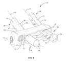
- FIG. 2shows the implant of FIG. 1 in a lateral perspective view.
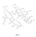
- FIG. 3shows the first and second plates of the implant of FIG. 1 in perspective view.
- FIG. 4shows the medial face of the first plate of the implant of FIG. 1 .
- FIG. 5shows a cross section of the first plate of the implant of FIG. 1 along line V-V of FIG. 4 .
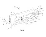
- FIG. 6shows the frame of the implant of FIG. 1
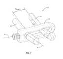
- FIG. 7shows the implant of FIG. 1 prior to clamping.
- FIG. 8shows a platform mounted to a guide pin.
- FIG. 9shows a guide dilator positioned to the interspinous space.
- FIG. 10shows the frame insertion swing arm disposed over the guide dilator.
- FIG. 11shows the frame being positioned via the channel of the frame insertion swing arm.
- FIG. 12shows insertion of the first and second plates disposed in the slot, with the plate insertion swing arm for the first plate partially removed to expose the first plate medial face.
- FIG. 13shows insertion of the implant positioned after insertion of the first and second plates, prior to clamping.
- FIG. 14shows the implant clamped to the spinous processes.
- the present inventionis directed to an implant 20 for spinal fusion that attaches to adjacent spinous processes 14 , 16 to fixate the corresponding vertebrae 10 , 12 relative to the other.
- the implant 20includes two fixation plates 30 , 40 and an interconnecting frame 50 .
- the fixation plates 30 , 40are disposed on respective lateral sides of adjacent spinous processes 14 , 16 , and the frame 50 extends laterally through the corresponding interspinous space 18 .
- the fixation plates 30 , 40 and frame 50are advantageously inserted, and locked together, using a percutaneous approach.
- the implant 20 of FIG. 1includes first and second plates 30 , 40 , a frame 50 , and a locking element 70 .
- the first plate 30is an elongate member that extends along a curving longitudinal axis 31 . As such, the first plate 30 is longitudinally curving, as shown in FIG. 4 .
- the first plate 30may be divided into a superior section 36 , an intervening intermediate section 37 , and an inferior section 38 , which are arranged sequentially in abutting relationship along the axis 31 .
- the superior endmay be relatively flat, while the inferior end advantageously is in the form of a tapering tip 39 .
- the intermediate section 37has a reduced cross section compared to the superior and inferior sections 36 , 38 , advantageously with suitable smooth transitions therebetween.
- the main or base portion 32 of the first plate 30has a generally flat medial face 33 , and advantageously has a generally D-shaped cross section normal to the longitudinal axis 31 .
- the medial face 33has plurality projections or teeth thereon, which extend medially away from the longitudinal axis 31 . These projections 34 are for biting into the spinous processes 14 , 16 when the implant 20 is clamped thereto, as discussed further below.
- the “diameter” of the base portion 32excluding the tip 39 but including the teeth 34 , is advantageously slightly smaller than the “diameter” of large part of tip 39 , such that the base portion 32 fits within the profile of the tip 39 projected along the longitudinal axis 31 .
- This arrangementallows the majority of the first plate 30 to be slid into a hollow delivery tube 142 (see further discussion below) leaving just the tip 39 exposed, with the tube 142 being not larger in diameter than the tip 39 .
- the second plate 40is likewise an elongate member that extends along a curving longitudinal axis 41 . As such, the second plate 40 is longitudinally curving.
- the second plate 40may be divided into a superior section 46 , an intervening intermediate section 47 , and an inferior section 48 , which are arranged sequentially in abutting relationship along the axis 41 .
- the superior endmay be relatively flat, while the inferior end advantageously is in the form of a tapering tip 49 .
- the intermediate section 47has a reduced cross section compared to the superior and inferior sections 46 , 48 , advantageously with suitable smooth transitions therebetween.
- the main or base portion 42 of the second plate 40has a generally flat medial face 43 , and advantageously has a generally D-shaped cross section normal to the longitudinal axis 41 .
- the medial face 43has a plurality of projections or teeth 44 thereon, which extend medially away from the longitudinal axis 41 .
- the teeth 44 on the second plate 40are for biting into the spinous processes 14 , 16 when the implant 20 is clamped thereto, as discussed further below.
- the “diameter” of the base portion 42excluding the tip 49 but including the teeth 44 , is advantageously slightly smaller than the “diameter” of large part of tip 49 , such that the base portion fits within the profile of the tip 49 projected along the longitudinal axis 41 .
- This arrangementallows the majority of the second plate 40 to be slid into a hollow delivery tube 142 leaving just the tip 49 exposed, with the tube 142 being not larger in diameter than the tip 49 .
- the first and second plates 30 , 40may be substantially mirror images of each other, although this is not required in all embodiments.
- the frame 50is an elongate member that advantageously extends along an associated longitudinal axis 51 from a proximal section 52 to a distal section 54 , as shown in FIG. 6 .
- the frame 50includes a longitudinal slot 60 that is sized and configured to accept the first and second plates 30 , 40 therethrough, with the slot 60 being in both the proximal section 52 and the distal section 54 .
- the slot 60may be relatively uniform in height 61 , but is advantageously variable in height.
- FIG. 6shows the slot 60 with two spaced apart enlarged height sections 62 interleaved with two spaced apart reduced height sections 64 , with suitable smooth transitions therebetween.
- the proximal section 52includes a longitudinal bore 52 extending into the slot 60 .
- the bore 53is sized and configured to engagingly receive the locking member 70 , as described further below.
- the distal and proximal ends of the slot 60are advantageously fully enclosed.
- the distal section 54advantageously tapers distally to form a tapered tip 56 .
- the frame 50is advantageously rigid, although flexible frames 50 may alternatively be used in some embodiments.
- the locking element 70helps clamp the first and second plates 30 , 40 to the spinous processes 14 , 16 by moving at least the second plate 40 longitudinally toward the first plate 30 .
- the locking element 70is illustrated as a setscrew, although other types of locking elements, such as barbed one-way pins, quarter-turn fasteners, and the like may alternatively be employed.
- the implant 20is formed of suitable biocompatible materials, such as stainless steel, titanium and its alloys, polymers such as PEEK, and the like.
- the implant 20may be implanted by positioning the frame 50 in the interspinous space 18 so that the longitudinal axis 51 passes through the sagittal plane defined by the adjacent spinous processes 14 , 16 .
- the frame 50should be oriented so that the slot height 61 is parallel to the anatomical axial plane.
- the locking element 70is advantageously partially inserted into the bore 53 prior to the placement of the frame 50 .
- the first and second plates 30 , 40are then positioned transverse, e.g., perpendicular, to the frame 50 , advantageously through the enlarged height sections 62 of the slot 60 , so that each plate 30 , 40 extends proximate the superior and inferior spinous processes 14 , 16 on respective lateral sides thereof.
- the first and second plates 30 , 40are disposed through the slot 60 so that the intermediate sections 38 , 48 rest in the corresponding enlarged height sections 62 of the slot 60 .
- the first and second plates 30 , 40are separated by a distance D insert (measured along axis 51 ).
- the locking element 70is then advanced proximally relative to the frame 50 so as to apply a force to the second plate 40 along axis 51 .
- This forceis typically a result of the locking element 70 abutting the second plate 40 directly, but may be indirect, such as through an intervening shim, if desired.
- This forcecauses second plate 40 to displace distally out of enlarged section 62 and into the distally adjoining reduced section 64 .
- the displacement force of the locking element 70causes the frame 50 to in effect “pull back” so that the distal tip 56 of the frame 50 is moved closer to the sagittal plane through the interspinous space 18 .
- Further displacement of the frame 50causes the plates 30 , 40 to be clamped to the spinous processes 14 , 16 , with the teeth 34 , 44 of the plates 30 , 40 biting into the spinous processes 14 , 16 .
- the first and second plates 30 , 40are separated by a distance D clamp , which is smaller than distance D insert .
- This clamping of the implant 20 to the spinous processes 14 , 16immobilizes the spinous processes 14 , 16 relative to each other, thereby stabilizing the vertebrae 10 , 12 and the corresponding disc space suitably for fusion to occur.
- the above processmay be carried out using a relatively large access with a posterior approach, similar to that described in U.S. Pat. Nos. 7,048,736 and 7,727,233.
- the implantation processis advantageously carried out percutaneously, as described further below.
- the implant 20may be percutaneously implanted using an installation assembly 100 as shown in FIGS. 8-14 .
- a reference guidesuch as a Steinman pin 102
- a platform 104is then secured to the pin 102 , such as by routing the pin 102 trough a pin boss 110 on the platform 104 and securing the platform 104 thereto.
- the platform 104is advantageously mounted to the pin 102 at a predetermined height along the pin 102 that allows the swing arm installation described below to position the components of the implant 20 as desired. It should be understood that the platform 104 is also supported by ways not shown, such as legs and the like, to the surgical table.
- the position of the platform 104is locked relative to the patient and the surgical table once positioned properly on the pin 102 . As such, the pin 102 may be removed at this point of the surgical procedure if desired.
- a guide dilator 120is then attached to the platform 104 so that it rotates about an axis 106 parallel to the spinal column.
- the guide dilator 120has a tapered tip 122 , and includes a pivot arm section 124 and a curvate section 126 .
- the pivot arm section 124extends outward from the platform 104 , and advantageously includes a short jog section as illustrated.
- the curvate section 126is curved at a uniform radius of curvature that enables the tip 122 to stop in the desired interspinous space 18 when the platform 104 is positioned correctly. If not previously removed, the pin 102 should be removed at this point in the procedure.
- a frame insertion swing arm 130is then attached to the platform 104 .
- the frame insertion swing arm 130includes a curvate guide tube 132 with a channel 134 .
- the guide dilator 120slides within the channel 134 to guide the distal end of the frame insertion swing arm 130 to the desired location.
- the guide dilator 120is then removed and the frame 50 inserted into the channel 134 .
- the frame 50is then advanced down the channel 134 using any suitable means until the frame 50 is properly disposed through the interspinous space 18 .
- a plate insertion swing arm 140is then attached to the platform 104 for rotation about a laterally running axis.
- the plate insertion swing arm 140includes a curved hollow tube 142 that curves at a suitable rate to extend through the frame slot 60 when swung into position.
- the first plate 30is advantageously preloaded into the distal portion of the hollow tube 142 before rotating the plate insertion swing arm 130 down into position.
- the tip 39 of the first plate 30is tapered, as discussed above, in order to dilate the affected tissue during this swinging action.
- the tissueis protected from the teeth 34 of the first plate 30 because the teeth 34 are disposed inside the hollow tube 142 .
- another plate insertion swing arm 140is used to insert the second plate 40 through the slot 60 of the frame 50 .
- the plate insertion swing arms 140are rotated back out of position while using a suitable push rod or the like to expel the plates 30 , 40 from the corresponding hollow tubes 142 .
- the plate insertion swing arms 140are then removed from the platform 104 .
- a suitable tool(not shown) is then advanced through the channel 134 to actuate the locking mechanism 70 to clamp the implant 20 to the spinous processes 14 , 16 .
- the frame insertion swing arm 130is then removed, followed by the pin 102 .
- Such a proceduremay be accomplished with three small incisions, one each for the frame 50 and the two plates 30 , 40 .
- Each of the components of the implant 20is implanted using a percutaneous, swing arm-based approach to properly position the components, and subsequently clamp the implant 20 in position. The use of such a percutaneous method allows for less surgical damage and quicker recovery.
- the swing arms 130 , 140 and guide dilator 120 discussed abovemay be pivotally mounted to the platform 104 in any suitable fashion, such as via C-shaped snap on sections, clamshell connectors, or the like.
- the swing arms 130 , 140 and guide dilator 120 discussed abovemay also have corresponding positive stops (not shown) on the platform 104 to prevent over-rotating them beyond their respective desired positions.
- the angle ⁇ between the frame axis 51 and the axis 31 of first plate 30 (or axis 41 of second plate 40 )may be 90°, i.e. perpendicular.
- the reduced cross sectional shape of the intermediate sections 37 , 47not only allows the plates 30 , 40 to be moved into the reduced height sections 64 of slot 60 , but also allows for small angular variations, such as ⁇ 15° or less from perpendicular, for angle ⁇ so as to accommodate spinal morphological variations between the vertebrae 10 , 12 .
Landscapes
- Health & Medical Sciences (AREA)
- Orthopedic Medicine & Surgery (AREA)
- Life Sciences & Earth Sciences (AREA)
- Neurology (AREA)
- Surgery (AREA)
- Heart & Thoracic Surgery (AREA)
- Engineering & Computer Science (AREA)
- Biomedical Technology (AREA)
- Nuclear Medicine, Radiotherapy & Molecular Imaging (AREA)
- Medical Informatics (AREA)
- Molecular Biology (AREA)
- Animal Behavior & Ethology (AREA)
- General Health & Medical Sciences (AREA)
- Public Health (AREA)
- Veterinary Medicine (AREA)
- Prostheses (AREA)
- Surgical Instruments (AREA)
Abstract
Description
The present invention relates generally to spinal stabilization, and more particularly to spinal fusion implants and procedures for implanting the same, particularly percutaneously.
A wide variety of spinal fusion devices are used following partial or total discectomies for stabilization of the spine at that site. Many such devices are secured extradiscally, such as to the pedicles or spinous processes. For example, the SPIRE brand fusion products available from Medtronic, Inc. of Minneapolis, Minn. are typically secured to the spinous processes. See also the devices and methods disclosed in U.S. Pat. Nos. 7,048,736 and 7,727,233. The implantation of such devices may involve significant muscle dissection and associated surgical time, as they are typically ill suited for minimally invasive surgical techniques. As a result, use of these devices may require significant recovery time. Thus, while numerous spinal fusion stabilization devices have been proposed, there remains a need for alternative approaches, particularly those suited for percutaneous implantation.
The present invention provides a spinal implant that helps stabilize vertebrae for fusion. The implant is particularly adapted for percutaneous implantation, but may also be used with other access techniques. The implant, in one or more embodiments, includes first and second plates that extend through a slot in a frame. When installed, the frame extends laterally through the interspinous space, and the plates extend superiorly-inferiorly along respective lateral sides of the spinous processes. The plates are moved toward one another and relative to the slot to clamp the implant to the spinous processes.
In some embodiments, the present invention provides a spinal implant device comprising a first plate, a second plate, a frame, and a locking element. The first plate curvingly extends along a first curved longitudinal axis and has a first medial face configured to abut adjacent spinous processes with biting projections thereon. The second plate curvingly extends along a second curved longitudinal axis and has a second medial face configured to abut the adjacent spinous processes with biting projections thereon. The frame extends along a third curved longitudinal axis and has a longitudinal slot therethrough. The first and second plates are disposed through the slot such that the first and second axes are transverse to the third axis and the first and second medial faces face toward each other in spaced relation. The locking element engages a proximal end of the frame and is longitudinally moveable relative to the frame such that longitudinal displacement of the locking element toward a distal end of the frame narrows a distance between the first plate and the second plate. In some embodiments, longitudinal displacement of the locking element toward a distal end of the frame causes the first and second plates to enter relatively narrower sections of the slot. The first plate may comprise first and second end sections, with an intermediate portion disposed therebetween, with the intermediate portion having a reduced cross section relative to the first and second end sections, and with the intermediate section disposed in the slot. The first end section of the first plate may advantageously have a tapered tip portion disposed opposite the intermediate section. The tapered tip portion may have the largest cross section of the first plate. The first plate may comprise an elongate base and the associated biting projections; wherein the base has a substantially D-shaped cross-section normal to the first axis, with the medial face being substantially flat. The second plate may be similar to the first plate, with the first and second plates being substantially mirror images of each other in some embodiments. The slot may have a variable height. For example, the slot may comprise two portions of enlarged height, disposed in longitudinally spaced relation.
In other embodiments, the first plate curvingly extends along a first curved longitudinal axis, and the first plate has a first medial face configured to abut adjacent spinous processes with biting projections thereon. The second plate curvingly extends along a second curved longitudinal axis, and the second plate has a second medial face configured to abut the adjacent spinous processes with biting projections thereon. The curvilinear frame extends along a third curved longitudinal axis and having a longitudinal slot therethrough. The first and second plates are disposed through the slot such that the first and second axes are transverse to the third axis and the first and second medial faces face toward each other in spaced relation. The locking element engages a proximal end of the frame and is longitudinally moveable relative to the frame. The implant is changeable from a first configuration to a second configuration. In the first configuration, the first and second plates are disposed a first distance apart. In the second configuration: the first and second plates are disposed a second distance apart, the second distance less than the first distance; the first and second plates are disposed more distally relative to frame than in the first configuration; the locking element is disposed more distally relative to the frame than in the first configuration. The slot may comprise a distal end, with the first plate abutting the distal end of the slot in the second configuration and the locking element abuts the second plate in the second configuration. The first plate may comprise first and second end sections, with an intermediate portion disposed therebetween, with the intermediate portion having a reduced cross section relative to the first and second end sections, and the intermediate section disposed in the slot. The slot may have variable height, with two spaced apart first sections of enlarged height and two spaced apart second sections of reduced height; one of the second sections of reduced height is disposed between the first sections of enlarged height and one of the first sections is disposed between the second sections. The first and second plates may be disposed in the first sections of the slot in the first configuration and disposed in the second sections of the slot in the second configuration.
In various embodiments, the present invention has one or more of the above attributes, alone or in any combination.
In one embodiment, the present invention is directed to animplant 20 for spinal fusion that attaches to adjacentspinous processes corresponding vertebrae implant 20 includes twofixation plates frame 50. Thefixation plates spinous processes frame 50 extends laterally through the correspondinginterspinous space 18. Thefixation plates frame 50 are advantageously inserted, and locked together, using a percutaneous approach.
One embodiment of theimplant 20 is shown inFIGS. 1-7 . Theimplant 20 ofFIG. 1 includes first andsecond plates frame 50, and alocking element 70. Thefirst plate 30 is an elongate member that extends along a curvinglongitudinal axis 31. As such, thefirst plate 30 is longitudinally curving, as shown inFIG. 4 . Thefirst plate 30 may be divided into asuperior section 36, an interveningintermediate section 37, and aninferior section 38, which are arranged sequentially in abutting relationship along theaxis 31. As can be seen, the superior end may be relatively flat, while the inferior end advantageously is in the form of a taperingtip 39. Theintermediate section 37 has a reduced cross section compared to the superior andinferior sections base portion 32 of thefirst plate 30 has a generally flatmedial face 33, and advantageously has a generally D-shaped cross section normal to thelongitudinal axis 31. Themedial face 33 has plurality projections or teeth thereon, which extend medially away from thelongitudinal axis 31. Theseprojections 34 are for biting into the spinous processes14,16 when theimplant 20 is clamped thereto, as discussed further below. The “diameter” of thebase portion 32, excluding thetip 39 but including theteeth 34, is advantageously slightly smaller than the “diameter” of large part oftip 39, such that thebase portion 32 fits within the profile of thetip 39 projected along thelongitudinal axis 31. This arrangement allows the majority of thefirst plate 30 to be slid into a hollow delivery tube142 (see further discussion below) leaving just thetip 39 exposed, with thetube 142 being not larger in diameter than thetip 39.
Thesecond plate 40 is likewise an elongate member that extends along a curvinglongitudinal axis 41. As such, thesecond plate 40 is longitudinally curving. Thesecond plate 40 may be divided into asuperior section 46, an interveningintermediate section 47, and aninferior section 48, which are arranged sequentially in abutting relationship along theaxis 41. As can be seen, the superior end may be relatively flat, while the inferior end advantageously is in the form of a tapering tip49. Theintermediate section 47 has a reduced cross section compared to the superior andinferior sections base portion 42 of thesecond plate 40 has a generally flatmedial face 43, and advantageously has a generally D-shaped cross section normal to thelongitudinal axis 41. Themedial face 43 has a plurality of projections orteeth 44 thereon, which extend medially away from thelongitudinal axis 41. Like theteeth 34 of thefirst plate 30, theteeth 44 on thesecond plate 40 are for biting into the spinous processes14,16 when theimplant 20 is clamped thereto, as discussed further below. The “diameter” of thebase portion 42, excluding the tip49 but including theteeth 44, is advantageously slightly smaller than the “diameter” of large part of tip49, such that the base portion fits within the profile of the tip49 projected along thelongitudinal axis 41. This arrangement allows the majority of thesecond plate 40 to be slid into ahollow delivery tube 142 leaving just the tip49 exposed, with thetube 142 being not larger in diameter than the tip49.
The first andsecond plates
Theframe 50 is an elongate member that advantageously extends along an associated longitudinal axis51 from a proximal section52 to a distal section54, as shown inFIG. 6 . Theframe 50 includes alongitudinal slot 60 that is sized and configured to accept the first andsecond plates slot 60 being in both the proximal section52 and the distal section54. Theslot 60 may be relatively uniform in height61, but is advantageously variable in height. For example,FIG. 6 shows theslot 60 with two spaced apartenlarged height sections 62 interleaved with two spaced apart reducedheight sections 64, with suitable smooth transitions therebetween. The proximal section52 includes a longitudinal bore52 extending into theslot 60. Thebore 53 is sized and configured to engagingly receive the lockingmember 70, as described further below. Other than thebore 60, the distal and proximal ends of theslot 60 are advantageously fully enclosed. The distal section54 advantageously tapers distally to form a taperedtip 56. Theframe 50 is advantageously rigid, althoughflexible frames 50 may alternatively be used in some embodiments.
The lockingelement 70 helps clamp the first andsecond plates second plate 40 longitudinally toward thefirst plate 30. The lockingelement 70 is illustrated as a setscrew, although other types of locking elements, such as barbed one-way pins, quarter-turn fasteners, and the like may alternatively be employed.
Theimplant 20 is formed of suitable biocompatible materials, such as stainless steel, titanium and its alloys, polymers such as PEEK, and the like.
Theimplant 20 may be implanted by positioning theframe 50 in theinterspinous space 18 so that the longitudinal axis51 passes through the sagittal plane defined by the adjacent spinous processes14,16. Theframe 50 should be oriented so that the slot height61 is parallel to the anatomical axial plane. The lockingelement 70 is advantageously partially inserted into thebore 53 prior to the placement of theframe 50. The first andsecond plates frame 50, advantageously through theenlarged height sections 62 of theslot 60, so that eachplate second plates slot 60 so that theintermediate sections enlarged height sections 62 of theslot 60. After insertion, prior to clamping, the first andsecond plates element 70 is then advanced proximally relative to theframe 50 so as to apply a force to thesecond plate 40 along axis51. This force is typically a result of the lockingelement 70 abutting thesecond plate 40 directly, but may be indirect, such as through an intervening shim, if desired. This force causessecond plate 40 to displace distally out ofenlarged section 62 and into the distally adjoining reducedsection 64. As thesecond plate 40 presses against the spinous processes14,16, the displacement force of the lockingelement 70 causes theframe 50 to in effect “pull back” so that thedistal tip 56 of theframe 50 is moved closer to the sagittal plane through theinterspinous space 18. This causes thefirst plate 30 to move out of its correspondingenlarged section 62 of theslot 60 and into the distally adjoining reducedsection 64. Further displacement of theframe 50 causes theplates teeth plates second plates implant 20 to the spinous processes14,16 immobilizes the spinous processes14,16 relative to each other, thereby stabilizing thevertebrae
The above process may be carried out using a relatively large access with a posterior approach, similar to that described in U.S. Pat. Nos. 7,048,736 and 7,727,233. However, the implantation process is advantageously carried out percutaneously, as described further below.
Theimplant 20 may be percutaneously implanted using aninstallation assembly 100 as shown inFIGS. 8-14 . A reference guide, such as aSteinman pin 102, is directed to the desiredinterspinous space 18. Aplatform 104 is then secured to thepin 102, such as by routing thepin 102 trough apin boss 110 on theplatform 104 and securing theplatform 104 thereto. Theplatform 104 is advantageously mounted to thepin 102 at a predetermined height along thepin 102 that allows the swing arm installation described below to position the components of theimplant 20 as desired. It should be understood that theplatform 104 is also supported by ways not shown, such as legs and the like, to the surgical table. The position of theplatform 104 is locked relative to the patient and the surgical table once positioned properly on thepin 102. As such, thepin 102 may be removed at this point of the surgical procedure if desired. A guide dilator120 is then attached to theplatform 104 so that it rotates about anaxis 106 parallel to the spinal column. The guide dilator120 has a taperedtip 122, and includes apivot arm section 124 and acurvate section 126. Thepivot arm section 124 extends outward from theplatform 104, and advantageously includes a short jog section as illustrated. Thecurvate section 126 is curved at a uniform radius of curvature that enables thetip 122 to stop in the desiredinterspinous space 18 when theplatform 104 is positioned correctly. If not previously removed, thepin 102 should be removed at this point in the procedure. A frameinsertion swing arm 130 is then attached to theplatform 104. The frameinsertion swing arm 130 includes acurvate guide tube 132 with achannel 134. The guide dilator120 slides within thechannel 134 to guide the distal end of the frameinsertion swing arm 130 to the desired location. The guide dilator120 is then removed and theframe 50 inserted into thechannel 134. Theframe 50 is then advanced down thechannel 134 using any suitable means until theframe 50 is properly disposed through theinterspinous space 18. A plateinsertion swing arm 140 is then attached to theplatform 104 for rotation about a laterally running axis. The plateinsertion swing arm 140 includes a curvedhollow tube 142 that curves at a suitable rate to extend through theframe slot 60 when swung into position. Thefirst plate 30 is advantageously preloaded into the distal portion of thehollow tube 142 before rotating the plateinsertion swing arm 130 down into position. Thetip 39 of thefirst plate 30 is tapered, as discussed above, in order to dilate the affected tissue during this swinging action. The tissue is protected from theteeth 34 of thefirst plate 30 because theteeth 34 are disposed inside thehollow tube 142. Similarly, another plateinsertion swing arm 140 is used to insert thesecond plate 40 through theslot 60 of theframe 50. Once theplates slot 60, the plateinsertion swing arms 140 are rotated back out of position while using a suitable push rod or the like to expel theplates hollow tubes 142. The plateinsertion swing arms 140 are then removed from theplatform 104. A suitable tool (not shown) is then advanced through thechannel 134 to actuate thelocking mechanism 70 to clamp theimplant 20 to the spinous processes14,16. The frameinsertion swing arm 130 is then removed, followed by thepin 102. Such a procedure may be accomplished with three small incisions, one each for theframe 50 and the twoplates implant 20 is implanted using a percutaneous, swing arm-based approach to properly position the components, and subsequently clamp theimplant 20 in position. The use of such a percutaneous method allows for less surgical damage and quicker recovery.
Theswing arms platform 104 in any suitable fashion, such as via C-shaped snap on sections, clamshell connectors, or the like. Theswing arms platform 104 to prevent over-rotating them beyond their respective desired positions.
The angle β between the frame axis51 and theaxis 31 of first plate30 (oraxis 41 of second plate40) may be 90°, i.e. perpendicular. However, the reduced cross sectional shape of theintermediate sections plates height sections 64 ofslot 60, but also allows for small angular variations, such as ±15° or less from perpendicular, for angle β so as to accommodate spinal morphological variations between thevertebrae
The discussions above have been in the context of theplates teeth
All U.S. patents and patent application publications mentioned above are hereby incorporated herein by reference in their entirety.
The present invention may, of course, be carried out in other specific ways than those herein set forth without departing from the scope of the invention. The present embodiments are, therefore, to be considered in all respects as illustrative and not restrictive, and all changes coming within the meaning and equivalency range of the appended claims are intended to be embraced therein.
Claims (20)
1. A spinal implant device comprising:
a first plate includes first and second end sections, with an intermediate portion disposed therebetween and the first plate curvingly extending along a first curved longitudinal axis such that the first end, the second end and the intermediate portion of the first plate form an arcuate shape along a length of the first plate and having a first medial face configured to abut adjacent spinous processes and having biting projections thereon;
a second plate includes first and second end sections, with an intermediate portion disposed therebetween and the second plate curvingly extending along a second curved longitudinal axis such that the first end, the second end and the intermediate portion of the second plate form an arcuate shape along a length of the second plate and having a second medial face configured to abut the adjacent spinous processes and having biting projections thereon;
a frame extending along a third curved longitudinal axis and having a longitudinal slot therethrough;
the first and second plates disposed through the slot such that the first and second axes are transverse to the third axis and the first and second medial faces face toward each other in spaced relation;
a locking element engaging a proximal end of the frame and longitudinally moveable relative to the frame such that longitudinal displacement of the locking element toward a distal end of the frame narrows a distance between the first plate and the second plate.
2. The spinal implant ofclaim 1 wherein longitudinal displacement of the locking element toward a distal end of the frame causes the first and second plates to enter relatively narrower sections of the slot.
3. The spinal implant ofclaim 1 : wherein the intermediate portion has a reduced cross section relative to the first and second end sections; wherein the intermediate section is disposed in the slot.
4. The spinal implant ofclaim 3 wherein the first end section of the first plate has a tapered tip portion disposed opposite the intermediate section.
5. The spinal implant ofclaim 4 wherein the tapered tip portion has the largest cross section of the first plate.
6. The spinal implant ofclaim 1 wherein the first plate comprises an elongate base and the associated biting projections; wherein the base has a substantially D-shaped cross-section normal to the first axis, with the medial face being substantially flat.
7. The spinal implant ofclaim 1 wherein the slot has a variable height.
8. The spinal implant ofclaim 7 wherein the slot comprises two portions of enlarged height, disposed in longitudinally spaced relation.
9. The spinal implant ofclaim 1 wherein the first and second plates are substantially mirror images of each other.
10. The spinal implant ofclaim 1 wherein the locking element is a screw.
11. The spinal implant ofclaim 1 wherein the frame further comprises proximal and distal longitudinal sections; wherein the distal section comprises a tip that tapers away from the proximal section; wherein the slot extends in both the proximal and distal sections.
12. The spinal implant ofclaim 11 wherein the proximal section comprises a longitudinally extending bore sized and configured to engagingly receive the locking element.
13. The spinal implant ofclaim 1 wherein the locking element abuts the second plate.
14. The spinal implant ofclaim 1 wherein the first and second axes are substantially perpendicular to the third axis.
15. A spinal implant, comprising:
a first plate includes first and second end sections, with an intermediate portion disposed therebetween and the first plate curvingly extending along a first curved longitudinal axis such that the first end, the second end and the intermediate portion of the first plate form an arcuate shape along a length of the first plate; the first plate having a first medial face configured to abut adjacent spinous processes with biting projections thereon;
a second plate includes first and second end sections, with an intermediate portion disposed therebetween and the second plate curvingly extending along a second curved longitudinal axis such that the first end, the second end and the intermediate portion of the second plate form an arcuate shape along a length of the second plate; the second plate having a second medial face configured to abut the adjacent spinous processes with biting projections thereon;
a curvilinear frame extending along a third curved longitudinal axis and having a longitudinal slot therethrough;
the first and second plates disposed through the slot such that the first and second axes are transverse to the third axis and the first and second medial faces face toward each other in spaced relation;
a locking element engaging a proximal end of the frame and longitudinally moveable relative to the frame;
the implant changeable from a first configuration to a second configuration;
wherein, in the first configuration, the first and second plates are disposed a first distance apart;
wherein, in the second configuration:
the first and second plates are disposed a second distance apart, the second distance less than the first distance;
the first and second plates are disposed more distally relative to frame than in the first configuration;
the locking element is disposed more distally relative to the frame than in the first configuration.
16. The spinal implant ofclaim 15 wherein the slot comprises a distal end; wherein the first plate abuts the distal end of the slot in the second configuration; wherein the locking element abuts the second plate in the second configuration.
17. The spinal implant ofclaim 15 : wherein the intermediate portion has a reduced cross section relative to the first and second end sections; wherein the intermediate section is disposed in the slot.
18. The spinal implant ofclaim 15 wherein the first and second plates are disposed substantially perpendicular to the third axis.
19. The spinal implant ofclaim 15 wherein the slot has variable height, with two spaced apart first sections of enlarged height and two spaced apart second sections of reduced height; wherein one of the second sections of reduced height is disposed between the first sections of enlarged height; wherein one of the first sections is disposed between the second sections.
20. The spinal implant ofclaim 19 wherein the first and second plates are disposed in the first sections of the slot in the first configuration; wherein the first and second plates are disposed in the second sections of the slot in the second configuration.
Priority Applications (1)
| Application Number | Priority Date | Filing Date | Title |
|---|---|---|---|
| US13/037,729US8562650B2 (en) | 2011-03-01 | 2011-03-01 | Percutaneous spinous process fusion plate assembly and method |
Applications Claiming Priority (1)
| Application Number | Priority Date | Filing Date | Title |
|---|---|---|---|
| US13/037,729US8562650B2 (en) | 2011-03-01 | 2011-03-01 | Percutaneous spinous process fusion plate assembly and method |
Publications (2)
| Publication Number | Publication Date |
|---|---|
| US20120226313A1 US20120226313A1 (en) | 2012-09-06 |
| US8562650B2true US8562650B2 (en) | 2013-10-22 |
Family
ID=46753762
Family Applications (1)
| Application Number | Title | Priority Date | Filing Date |
|---|---|---|---|
| US13/037,729Active2032-01-24US8562650B2 (en) | 2011-03-01 | 2011-03-01 | Percutaneous spinous process fusion plate assembly and method |
Country Status (1)
| Country | Link |
|---|---|
| US (1) | US8562650B2 (en) |
Cited By (13)
| Publication number | Priority date | Publication date | Assignee | Title |
|---|---|---|---|---|
| US20140358181A1 (en)* | 2007-01-29 | 2014-12-04 | Samy Abdou | Spinal stabilization systems and methods of use |
| US9456854B1 (en)* | 2007-11-15 | 2016-10-04 | N. Garrett Powell | Spinous process clamp and fixation device |
| US10034693B2 (en) | 2016-07-07 | 2018-07-31 | Mark S. Stern | Spinous laminar clamp assembly |
| US10543107B2 (en) | 2009-12-07 | 2020-01-28 | Samy Abdou | Devices and methods for minimally invasive spinal stabilization and instrumentation |
| US10548740B1 (en) | 2016-10-25 | 2020-02-04 | Samy Abdou | Devices and methods for vertebral bone realignment |
| US10575961B1 (en) | 2011-09-23 | 2020-03-03 | Samy Abdou | Spinal fixation devices and methods of use |
| US10695105B2 (en) | 2012-08-28 | 2020-06-30 | Samy Abdou | Spinal fixation devices and methods of use |
| US10857003B1 (en) | 2015-10-14 | 2020-12-08 | Samy Abdou | Devices and methods for vertebral stabilization |
| US10918498B2 (en) | 2004-11-24 | 2021-02-16 | Samy Abdou | Devices and methods for inter-vertebral orthopedic device placement |
| US10973648B1 (en) | 2016-10-25 | 2021-04-13 | Samy Abdou | Devices and methods for vertebral bone realignment |
| US11006982B2 (en) | 2012-02-22 | 2021-05-18 | Samy Abdou | Spinous process fixation devices and methods of use |
| US11173040B2 (en) | 2012-10-22 | 2021-11-16 | Cogent Spine, LLC | Devices and methods for spinal stabilization and instrumentation |
| US11179248B2 (en) | 2018-10-02 | 2021-11-23 | Samy Abdou | Devices and methods for spinal implantation |
Families Citing this family (5)
| Publication number | Priority date | Publication date | Assignee | Title |
|---|---|---|---|---|
| US9402656B2 (en)* | 2009-09-11 | 2016-08-02 | Globus Medical, Inc. | Spinous process fusion devices |
| US20120323276A1 (en)* | 2011-06-17 | 2012-12-20 | Bryan Okamoto | Expandable interspinous device |
| US9107703B2 (en)* | 2011-08-25 | 2015-08-18 | Alphatec Spine, Inc. | Apparatus and method for connecting surgical rods |
| EP2755605A4 (en)* | 2011-09-16 | 2015-10-28 | Lanx Inc | SEGMENTED THORN RESIDUE ANCHORING SYSTEM AND USE METHOD THEREFOR |
| FR3098385B1 (en) | 2019-07-08 | 2023-05-12 | Innospina Sarl | Interspinous vertebral implant and associated placement ancillary |
Citations (183)
| Publication number | Priority date | Publication date | Assignee | Title |
|---|---|---|---|---|
| US2677369A (en) | 1952-03-26 | 1954-05-04 | Fred L Knowles | Apparatus for treatment of the spinal column |
| US3648691A (en) | 1970-02-24 | 1972-03-14 | Univ Colorado State Res Found | Method of applying vertebral appliance |
| US4011602A (en) | 1975-10-06 | 1977-03-15 | Battelle Memorial Institute | Porous expandable device for attachment to bone tissue |
| DE2821678A1 (en) | 1978-05-12 | 1979-11-22 | Sulzer Ag | IMPLANT THAT CAN BE INSERTED BETWEEN NEIGHBORING Vertebrae |
| US4257409A (en) | 1978-04-14 | 1981-03-24 | Kazimierz Bacal | Device for treatment of spinal curvature |
| SU988281A1 (en) | 1981-06-26 | 1983-01-15 | За витель | Vertical column fixing device |
| US4554914A (en) | 1983-10-04 | 1985-11-26 | Kapp John P | Prosthetic vertebral body |
| US4573454A (en) | 1984-05-17 | 1986-03-04 | Hoffman Gregory A | Spinal fixation apparatus |
| US4604995A (en) | 1984-03-30 | 1986-08-12 | Stephens David C | Spinal stabilizer |
| US4686970A (en) | 1983-12-15 | 1987-08-18 | A. W. Showell (Surgicraft) Limited | Devices for spinal fixation |
| US4827918A (en) | 1985-08-15 | 1989-05-09 | Sven Olerud | Fixing instrument for use in spinal surgery |
| FR2623085A1 (en) | 1987-11-16 | 1989-05-19 | Breard Francis | SURGICAL IMPLANT FOR LIMITING THE RELATIVE MOVEMENT OF VERTEBRATES |
| SU1484348A1 (en) | 1987-03-04 | 1989-06-07 | Белорусский научно-исследовательский институт травматологии и ортопедии | Spinal column fixing device |
| FR2625097A1 (en) | 1987-12-23 | 1989-06-30 | Cote Sarl | INTER-EPINEUS PROSTHESIS COMPOSED IN A SEMI-ELASTIC MATERIAL AND COMPRISING A TRANSFILING EYE AT ITS END AND INTER-SPINOUS CUSHIONETS |
| US5047055A (en) | 1990-12-21 | 1991-09-10 | Pfizer Hospital Products Group, Inc. | Hydrogel intervertebral disc nucleus |
| US5092866A (en) | 1989-02-03 | 1992-03-03 | Breard Francis H | Flexible inter-vertebral stabilizer as well as process and apparatus for determining or verifying its tension before installation on the spinal column |
| FR2681525A1 (en) | 1991-09-19 | 1993-03-26 | Medical Op | Device for flexible or semi-rigid stabilisation of the spine, in particular of the human spine, by a posterior route |
| US5201734A (en) | 1988-12-21 | 1993-04-13 | Zimmer, Inc. | Spinal locking sleeve assembly |
| US5306275A (en) | 1992-12-31 | 1994-04-26 | Bryan Donald W | Lumbar spine fixation apparatus and method |
| FR2700941A1 (en) | 1993-02-03 | 1994-08-05 | Felman Daniel | Monobloc interspinal intervertebral fixation implant |
| FR2703239A1 (en) | 1993-03-30 | 1994-10-07 | Brio Bio Rhone Implant Medical | Pin for interspinal prosthesis |
| US5360430A (en) | 1993-07-29 | 1994-11-01 | Lin Chih I | Intervertebral locking device |
| US5366455A (en) | 1988-11-04 | 1994-11-22 | Surgicraft Limited | Pedicle engaging means |
| FR2707864A1 (en) | 1993-07-23 | 1995-01-27 | Taylor Jean | Surgical clamp for tensioning an osteosynthesis ligament |
| US5415661A (en) | 1993-03-24 | 1995-05-16 | University Of Miami | Implantable spinal assist device |
| US5437672A (en) | 1992-11-12 | 1995-08-01 | Alleyne; Neville | Spinal cord protection device |
| FR2717675A1 (en) | 1994-03-24 | 1995-09-29 | Taylor Jean | Shock-absorbing spacer block for location between adjacent vertebrae implanted during spinal surgery |
| US5454812A (en) | 1993-11-12 | 1995-10-03 | Lin; Chih-I | Spinal clamping device having multiple distance adjusting strands |
| FR2722088A1 (en) | 1994-07-08 | 1996-01-12 | Cahlik Marc Andre | Surgical implant for stabilising intervertebral spaces |
| FR2722087A1 (en) | 1994-07-08 | 1996-01-12 | Cahlik Marc Andre | Surgical implant for limiting relative movement of vertebrae |
| US5496318A (en) | 1993-01-08 | 1996-03-05 | Advanced Spine Fixation Systems, Inc. | Interspinous segmental spine fixation device |
| FR2724554A1 (en) | 1994-09-16 | 1996-03-22 | Voydeville Gilles | Fastening for artificial ligaments of inter-vertebral prosthesis |
| FR2725892A1 (en) | 1994-10-21 | 1996-04-26 | Felman Daniel | Vertebral implant insertion process using shape memory material |
| FR2730156A1 (en) | 1995-02-03 | 1996-08-09 | Textile Hi Tec | Inter-spinal wedge implant useful esp. for vertebral prosthesis |
| US5609634A (en) | 1992-07-07 | 1997-03-11 | Voydeville; Gilles | Intervertebral prosthesis making possible rotatory stabilization and flexion/extension stabilization |
| US5628756A (en) | 1993-01-06 | 1997-05-13 | Smith & Nephew Richards Inc. | Knotted cable attachment apparatus formed of braided polymeric fibers |
| US5645599A (en) | 1994-07-26 | 1997-07-08 | Fixano | Interspinal vertebral implant |
| US5674295A (en) | 1994-10-17 | 1997-10-07 | Raymedica, Inc. | Prosthetic spinal disc nucleus |
| US5676702A (en) | 1994-12-16 | 1997-10-14 | Tornier S.A. | Elastic disc prosthesis |
| US5690649A (en) | 1995-12-05 | 1997-11-25 | Li Medical Technologies, Inc. | Anchor and anchor installation tool and method |
| US5702452A (en) | 1995-01-23 | 1997-12-30 | Sofamor S.N.C. | Spinal osteosynthesis device with median hook and vertebral anchoring support |
| US5810815A (en) | 1996-09-20 | 1998-09-22 | Morales; Jose A. | Surgical apparatus for use in the treatment of spinal deformities |
| US5836948A (en) | 1997-01-02 | 1998-11-17 | Saint Francis Medical Technologies, Llc | Spine distraction implant and method |
| US5860977A (en) | 1997-01-02 | 1999-01-19 | Saint Francis Medical Technologies, Llc | Spine distraction implant and method |
| FR2775183A1 (en) | 1998-02-20 | 1999-08-27 | Jean Taylor | INTER-SPINOUS PROSTHESIS |
| US5976186A (en) | 1994-09-08 | 1999-11-02 | Stryker Technologies Corporation | Hydrogel intervertebral disc nucleus |
| US6022376A (en) | 1997-06-06 | 2000-02-08 | Raymedica, Inc. | Percutaneous prosthetic spinal disc nucleus and method of manufacture |
| US6048342A (en) | 1997-01-02 | 2000-04-11 | St. Francis Medical Technologies, Inc. | Spine distraction implant |
| US6068630A (en) | 1997-01-02 | 2000-05-30 | St. Francis Medical Technologies, Inc. | Spine distraction implant |
| US6132464A (en) | 1994-06-24 | 2000-10-17 | Paulette Fairant | Vertebral joint facets prostheses |
| FR2799948A1 (en) | 1999-10-22 | 2001-04-27 | Transco Esquisse | Connecting bar esp for lumbar arthrodesis has lateral rod fixings and central anchor for interspinal prosthesis |
| US20010016743A1 (en) | 1997-01-02 | 2001-08-23 | St. Francis Medical Technologies, Inc. | Spine distraction implant and method |
| US6293949B1 (en) | 2000-03-01 | 2001-09-25 | Sdgi Holdings, Inc. | Superelastic spinal stabilization system and method |
| EP1138268A1 (en) | 2000-03-21 | 2001-10-04 | Cousin Biotech (S.A.S.) | Device for the fixation of an interspinous wedge on the sacrum |
| US6352537B1 (en) | 1998-09-17 | 2002-03-05 | Electro-Biology, Inc. | Method and apparatus for spinal fixation |
| US6364883B1 (en) | 2001-02-23 | 2002-04-02 | Albert N. Santilli | Spinous process clamp for spinal fusion and method of operation |
| FR2816197A1 (en) | 2000-11-07 | 2002-05-10 | Jean Taylor | Interspinal prosthesis is X-shaped and is made from flexible material, two arms being compressed together and held in position by clip to introduce prosthesis |
| US6402750B1 (en) | 2000-04-04 | 2002-06-11 | Spinlabs, Llc | Devices and methods for the treatment of spinal disorders |
| US6440169B1 (en) | 1998-02-10 | 2002-08-27 | Dimso | Interspinous stabilizer to be fixed to spinous processes of two vertebrae |
| US6451019B1 (en) | 1998-10-20 | 2002-09-17 | St. Francis Medical Technologies, Inc. | Supplemental spine fixation device and method |
| US20020143331A1 (en) | 1998-10-20 | 2002-10-03 | Zucherman James F. | Inter-spinous process implant and method with deformable spacer |
| US20030045940A1 (en) | 2001-08-24 | 2003-03-06 | Robert Eberlein | Artificial intervertebral disc |
| US20030065330A1 (en) | 1998-10-20 | 2003-04-03 | St. Francis Medical Technologies, Inc. | Deflectable spacer for use as an interspinous process implant and method |
| US6582433B2 (en) | 2001-04-09 | 2003-06-24 | St. Francis Medical Technologies, Inc. | Spine fixation device and method |
| EP1330987A1 (en) | 2002-01-28 | 2003-07-30 | Biomet Merck France | Interspinous vertebral implant |
| US20030153915A1 (en) | 2002-02-08 | 2003-08-14 | Showa Ika Kohgyo Co., Ltd. | Vertebral body distance retainer |
| US6645207B2 (en) | 2000-05-08 | 2003-11-11 | Robert A. Dixon | Method and apparatus for dynamized spinal stabilization |
| US6695842B2 (en) | 1997-10-27 | 2004-02-24 | St. Francis Medical Technologies, Inc. | Interspinous process distraction system and method with positionable wing and method |
| US6709435B2 (en) | 2002-03-20 | 2004-03-23 | A-Spine Holding Group Corp. | Three-hooked device for fixing spinal column |
| US6723126B1 (en) | 2002-11-01 | 2004-04-20 | Sdgi Holdings, Inc. | Laterally expandable cage |
| US6733534B2 (en) | 2002-01-29 | 2004-05-11 | Sdgi Holdings, Inc. | System and method for spine spacing |
| US20040097931A1 (en) | 2002-10-29 | 2004-05-20 | Steve Mitchell | Interspinous process and sacrum implant and method |
| WO2004047691A1 (en) | 2002-11-21 | 2004-06-10 | Sdgi Holdings, Inc. | Systems and techniques for interbody spinal stablization with expandable devices |
| US6761720B1 (en) | 1999-10-15 | 2004-07-13 | Spine Next | Intervertebral implant |
| US20040199255A1 (en) | 2001-08-20 | 2004-10-07 | Claude Mathieu | Interspinal prosthesis |
| US20050010293A1 (en) | 2003-05-22 | 2005-01-13 | Zucherman James F. | Distractible interspinous process implant and method of implantation |
| WO2005009300A1 (en) | 2003-07-24 | 2005-02-03 | Byung-Kwan Choi | Prosthesis for vertebra |
| WO2005044118A1 (en) | 2003-10-24 | 2005-05-19 | Cousin Biotech, S.A.S. | Inter-blade support |
| US20050165398A1 (en) | 2004-01-26 | 2005-07-28 | Reiley Mark A. | Percutaneous spine distraction implant systems and methods |
| US20050203624A1 (en) | 2004-03-06 | 2005-09-15 | Depuy Spine, Inc. | Dynamized interspinal implant |
| US20050203512A1 (en) | 2004-03-09 | 2005-09-15 | Depuy Spine, Inc. | Posterior process dynamic spacer |
| US6946000B2 (en) | 2000-12-22 | 2005-09-20 | Spine Next | Intervertebral implant with deformable wedge |
| US20050228391A1 (en) | 2004-04-05 | 2005-10-13 | Levy Mark M | Expandable bone device |
| WO2005110258A1 (en) | 2004-05-17 | 2005-11-24 | Wooridul Spine Health Institute Co. | Spine insert |
| US20050261768A1 (en) | 2004-05-21 | 2005-11-24 | Trieu Hai H | Interspinous spacer |
| US20050288672A1 (en) | 2003-05-23 | 2005-12-29 | Nuvasive, Inc. | Devices to prevent spinal extension |
| US20060004447A1 (en) | 2004-06-30 | 2006-01-05 | Depuy Spine, Inc. | Adjustable posterior spinal column positioner |
| US20060015181A1 (en) | 2004-07-19 | 2006-01-19 | Biomet Merck France (50% Interest) | Interspinous vertebral implant |
| US20060064165A1 (en) | 2004-09-23 | 2006-03-23 | St. Francis Medical Technologies, Inc. | Interspinous process implant including a binder and method of implantation |
| US20060084985A1 (en) | 2004-10-20 | 2006-04-20 | The Board Of Trustees Of The Leland Stanford Junior University | Systems and methods for posterior dynamic stabilization of the spine |
| US20060085070A1 (en) | 2004-10-20 | 2006-04-20 | Vertiflex, Inc. | Systems and methods for posterior dynamic stabilization of the spine |
| US20060084988A1 (en) | 2004-10-20 | 2006-04-20 | The Board Of Trustees Of The Leland Stanford Junior University | Systems and methods for posterior dynamic stabilization of the spine |
| US20060084987A1 (en) | 2004-10-20 | 2006-04-20 | Kim Daniel H | Systems and methods for posterior dynamic stabilization of the spine |
| US20060085074A1 (en) | 2004-10-18 | 2006-04-20 | Kamshad Raiszadeh | Medical device systems for the spine |
| US20060084983A1 (en) | 2004-10-20 | 2006-04-20 | The Board Of Trustees Of The Leland Stanford Junior University | Systems and methods for posterior dynamic stabilization of the spine |
| US20060085069A1 (en) | 2004-10-20 | 2006-04-20 | The Board Of Trustees Of The Leland Stanford Junior University | Systems and methods for posterior dynamic stabilization of the spine |
| US20060089654A1 (en) | 2004-10-25 | 2006-04-27 | Lins Robert E | Interspinous distraction devices and associated methods of insertion |
| US20060089719A1 (en) | 2004-10-21 | 2006-04-27 | Trieu Hai H | In situ formation of intervertebral disc implants |
| US7041136B2 (en) | 2000-11-29 | 2006-05-09 | Facet Solutions, Inc. | Facet joint replacement |
| US20060106381A1 (en) | 2004-11-18 | 2006-05-18 | Ferree Bret A | Methods and apparatus for treating spinal stenosis |
| US20060106397A1 (en) | 2004-10-25 | 2006-05-18 | Lins Robert E | Interspinous distraction devices and associated methods of insertion |
| US7048736B2 (en) | 2002-05-17 | 2006-05-23 | Sdgi Holdings, Inc. | Device for fixation of spinous processes |
| US20060111728A1 (en) | 2004-10-05 | 2006-05-25 | Abdou M S | Devices and methods for inter-vertebral orthopedic device placement |
| US20060122620A1 (en) | 2004-10-20 | 2006-06-08 | The Board Of Trustees Of The Leland Stanford Junior University | Systems and methods for stabilizing the motion or adjusting the position of the spine |
| US20060129239A1 (en) | 2004-12-13 | 2006-06-15 | Kwak Seungkyu D | Artificial facet joint device having a compression spring |
| WO2006064356A1 (en) | 2004-12-16 | 2006-06-22 | Doellinger Horst | Implant for the treatment of lumbar spinal canal stenosis |
| US20060136060A1 (en) | 2002-09-10 | 2006-06-22 | Jean Taylor | Posterior vertebral support assembly |
| US7087083B2 (en) | 2001-03-13 | 2006-08-08 | Abbott Spine | Self locking fixable intervertebral implant |
| US20060184247A1 (en) | 2005-02-17 | 2006-08-17 | Edidin Avram A | Percutaneous spinal implants and methods |
| US20060184248A1 (en) | 2005-02-17 | 2006-08-17 | Edidin Avram A | Percutaneous spinal implants and methods |
| US20060195102A1 (en) | 2005-02-17 | 2006-08-31 | Malandain Hugues F | Apparatus and method for treatment of spinal conditions |
| US7101375B2 (en) | 1997-01-02 | 2006-09-05 | St. Francis Medical Technologies, Inc. | Spine distraction implant |
| US20060217726A1 (en) | 2003-02-19 | 2006-09-28 | Sdgi Holdings, Inc. | Interspinous device for impeding the movements of two sucessive vertebrae, and method for making a pad designed for it |
| US20060224159A1 (en) | 2005-03-31 | 2006-10-05 | Sdgi Holdings, Inc. | Intervertebral prosthetic device for spinal stabilization and method of implanting same |
| US20060235387A1 (en) | 2005-04-15 | 2006-10-19 | Sdgi Holdings, Inc. | Transverse process/laminar spacer |
| US20060235532A1 (en) | 2003-01-20 | 2006-10-19 | Abbott Spine | Unit for treatment of the degeneration of an intervertebral disc |
| US20060241757A1 (en) | 2005-03-31 | 2006-10-26 | Sdgi Holdings, Inc. | Intervertebral prosthetic device for spinal stabilization and method of manufacturing same |
| US20060241613A1 (en) | 2005-04-12 | 2006-10-26 | Sdgi Holdings, Inc. | Implants and methods for inter-transverse process dynamic stabilization of a spinal motion segment |
| US20060247623A1 (en) | 2005-04-29 | 2006-11-02 | Sdgi Holdings, Inc. | Local delivery of an active agent from an orthopedic implant |
| US20060247640A1 (en) | 2005-04-29 | 2006-11-02 | Sdgi Holdings, Inc. | Spinous process stabilization devices and methods |
| US20060264938A1 (en) | 2005-03-21 | 2006-11-23 | St. Francis Medical Technologies, Inc. | Interspinous process implant having deployable wing and method of implantation |
| US20060271049A1 (en) | 2005-04-18 | 2006-11-30 | St. Francis Medical Technologies, Inc. | Interspinous process implant having deployable wings and method of implantation |
| US20060271044A1 (en) | 2003-03-28 | 2006-11-30 | Piero Petrini | Interlaminar vertebral prosthesis |
| US20060282079A1 (en) | 2005-06-10 | 2006-12-14 | Depuy Spine, Inc. | Posterior dynamic stabilization systems and methods |
| US20060293663A1 (en) | 2005-04-21 | 2006-12-28 | Spine Wave, Inc. | Dynamic stabilization system for the spine |
| US20060293662A1 (en) | 2005-06-13 | 2006-12-28 | Boyer Michael L Ii | Spinous process spacer |
| US20070005064A1 (en) | 2005-06-27 | 2007-01-04 | Sdgi Holdings | Intervertebral prosthetic device for spinal stabilization and method of implanting same |
| US7163558B2 (en) | 2001-11-30 | 2007-01-16 | Abbott Spine | Intervertebral implant with elastically deformable wedge |
| US20070043362A1 (en) | 2005-02-17 | 2007-02-22 | Malandain Hugues F | Percutaneous spinal implants and methods |
| WO2007034516A1 (en) | 2005-09-21 | 2007-03-29 | Sintea Biotech S.P.A. | Device, kit and method for intervertebral stabilization |
| US7201751B2 (en) | 1997-01-02 | 2007-04-10 | St. Francis Medical Technologies, Inc. | Supplemental spine fixation device |
| US20070100340A1 (en) | 2005-10-27 | 2007-05-03 | Sdgi Holdings, Inc. | Intervertebral prosthetic device for spinal stabilization and method of implanting same |
| US20070123861A1 (en) | 2005-11-10 | 2007-05-31 | Sdgi Holdings, Inc. | Intervertebral prosthetic device for spinal stabilization and method of implanting same |
| US7238204B2 (en) | 2000-07-12 | 2007-07-03 | Abbott Spine | Shock-absorbing intervertebral implant |
| US20070162000A1 (en) | 2005-11-22 | 2007-07-12 | Richard Perkins | Adjustable spinous process spacer device and method of treating spinal stenosis |
| US20070167945A1 (en) | 2006-01-18 | 2007-07-19 | Sdgi Holdings, Inc. | Intervertebral prosthetic device for spinal stabilization and method of manufacturing same |
| US20070173822A1 (en) | 2006-01-13 | 2007-07-26 | Sdgi Holdings, Inc. | Use of a posterior dynamic stabilization system with an intradiscal device |
| US20070173823A1 (en) | 2006-01-18 | 2007-07-26 | Sdgi Holdings, Inc. | Intervertebral prosthetic device for spinal stabilization and method of implanting same |
| US20070191834A1 (en) | 2006-01-27 | 2007-08-16 | Sdgi Holdings, Inc. | Artificial spinous process for the sacrum and methods of use |
| US20070191833A1 (en) | 2006-01-27 | 2007-08-16 | Sdgi Holdings, Inc. | Spinal implants including a sensor and methods of use |
| US20070191837A1 (en) | 2006-01-27 | 2007-08-16 | Sdgi Holdings, Inc. | Interspinous devices and methods of use |
| US20070198091A1 (en) | 2005-12-06 | 2007-08-23 | Boyer Michael L | Facet joint prosthesis |
| US20070233081A1 (en) | 2004-05-11 | 2007-10-04 | Denis Pasquet | Self-Locking Device for Fastening an Intervertebral Implant |
| US20070233076A1 (en) | 2006-03-31 | 2007-10-04 | Sdgi Holdings, Inc. | Methods and instruments for delivering interspinous process spacers |
| US20070233089A1 (en) | 2006-02-17 | 2007-10-04 | Endius, Inc. | Systems and methods for reducing adjacent level disc disease |
| US20070233068A1 (en) | 2006-02-22 | 2007-10-04 | Sdgi Holdings, Inc. | Intervertebral prosthetic assembly for spinal stabilization and method of implanting same |
| US20070233074A1 (en) | 2006-03-16 | 2007-10-04 | Sdgi Holdings, Inc. | Expandable device for insertion between anatomical structures and a procedure utilizing same |
| US20070250060A1 (en) | 2006-04-24 | 2007-10-25 | Sdgi Holdings, Inc. | Expandable device for insertion between anatomical structures and a procedure utilizing same |
| EP1854433A1 (en) | 1999-10-22 | 2007-11-14 | Archus Orthopedics Inc. | Facet arthroplasty devices and methods |
| US20070270824A1 (en) | 2006-04-28 | 2007-11-22 | Warsaw Orthopedic, Inc. | Interspinous process brace |
| US20070270826A1 (en) | 2006-04-28 | 2007-11-22 | Sdgi Holdings, Inc. | Interosteotic implant |
| US20070270827A1 (en) | 2006-04-28 | 2007-11-22 | Warsaw Orthopedic, Inc | Adjustable interspinous process brace |
| US20070270823A1 (en) | 2006-04-28 | 2007-11-22 | Sdgi Holdings, Inc. | Multi-chamber expandable interspinous process brace |
| US20070270834A1 (en) | 2006-05-04 | 2007-11-22 | Sdgi Holdings, Inc. | Expandable device for insertion between anatomical structures and a procedure utilizing same |
| US20070270829A1 (en) | 2006-04-28 | 2007-11-22 | Sdgi Holdings, Inc. | Molding device for an expandable interspinous process implant |
| US20070270825A1 (en) | 2006-04-28 | 2007-11-22 | Sdgi Holdings, Inc. | Expandable interspinous process implant and method of installing same |
| US20070270828A1 (en) | 2006-04-28 | 2007-11-22 | Sdgi Holdings, Inc. | Interspinous process brace |
| US20070270874A1 (en) | 2006-04-24 | 2007-11-22 | Sdgi Holdings, Inc. | Surgical distraction device and procedure |
| US20070276368A1 (en) | 2006-05-23 | 2007-11-29 | Sdgi Holdings, Inc. | Systems and methods for adjusting properties of a spinal implant |
| US20070276497A1 (en) | 2006-05-23 | 2007-11-29 | Sdgi Holdings. Inc. | Surgical spacer |
| US20070272259A1 (en) | 2006-05-23 | 2007-11-29 | Sdgi Holdings, Inc. | Surgical procedure for inserting a device between anatomical structures |
| US20070276496A1 (en) | 2006-05-23 | 2007-11-29 | Sdgi Holdings, Inc. | Surgical spacer with shape control |
| US7306628B2 (en) | 2002-10-29 | 2007-12-11 | St. Francis Medical Technologies | Interspinous process apparatus and method with a selectably expandable spacer |
| US20080021460A1 (en) | 2006-07-20 | 2008-01-24 | Warsaw Orthopedic Inc. | Apparatus for insertion between anatomical structures and a procedure utilizing same |
| US7335203B2 (en) | 2003-02-12 | 2008-02-26 | Kyphon Inc. | System and method for immobilizing adjacent spinous processes |
| US20080114357A1 (en) | 2006-11-15 | 2008-05-15 | Warsaw Orthopedic, Inc. | Inter-transverse process spacer device and method for use in correcting a spinal deformity |
| US20080114456A1 (en) | 2006-11-15 | 2008-05-15 | Warsaw Orthopedic, Inc. | Spinal implant system |
| US20080114358A1 (en) | 2006-11-13 | 2008-05-15 | Warsaw Orthopedic, Inc. | Intervertebral Prosthetic Assembly for Spinal Stabilization and Method of Implanting Same |
| US7377942B2 (en) | 2003-08-06 | 2008-05-27 | Warsaw Orthopedic, Inc. | Posterior elements motion restoring device |
| US20080147190A1 (en) | 2006-12-14 | 2008-06-19 | Warsaw Orthopedic, Inc. | Interspinous Process Devices and Methods |
| US20080161818A1 (en) | 2005-02-08 | 2008-07-03 | Henning Kloss | Spinous Process Distractor |
| US20080167685A1 (en) | 2007-01-05 | 2008-07-10 | Warsaw Orthopedic, Inc. | System and Method For Percutanously Curing An Implantable Device |
| US20080215094A1 (en) | 2005-06-28 | 2008-09-04 | Jean Taylor | Equipment for Surgical Treatment of Two Vertebrae |
| US7445637B2 (en) | 2001-08-08 | 2008-11-04 | Jean Taylor | Vertebra stabilizing assembly |
| US20080281361A1 (en) | 2007-05-10 | 2008-11-13 | Shannon Marlece Vittur | Posterior stabilization and spinous process systems and methods |
| US20080281360A1 (en) | 2007-05-10 | 2008-11-13 | Shannon Marlece Vittur | Spinous process implants and methods |
| US20090062915A1 (en) | 2007-08-27 | 2009-03-05 | Andrew Kohm | Spinous-process implants and methods of using the same |
| US20090105773A1 (en) | 2007-10-23 | 2009-04-23 | Warsaw Orthopedic, Inc. | Method and apparatus for insertion of an interspinous process device |
| US7604652B2 (en) | 2005-10-11 | 2009-10-20 | Impliant Ltd. | Spinal prosthesis |
| US20100121379A1 (en) | 2006-01-27 | 2010-05-13 | U.S. Spinal Technologies, Llc | Pedicle and non-pedicle based interspinous and lateral spacers |
| US20110066186A1 (en)* | 2009-09-11 | 2011-03-17 | Boyer Ii Michael Lee | Spinous Process Fusion Devices |
| US8157842B2 (en)* | 2009-06-12 | 2012-04-17 | Kyphon Sarl | Interspinous implant and methods of use |
| US8287569B1 (en)* | 2007-11-15 | 2012-10-16 | Powell N Garrett | Modular system and method for fixation of spinous processes |
- 2011
- 2011-03-01USUS13/037,729patent/US8562650B2/enactiveActive
Patent Citations (192)
| Publication number | Priority date | Publication date | Assignee | Title |
|---|---|---|---|---|
| US2677369A (en) | 1952-03-26 | 1954-05-04 | Fred L Knowles | Apparatus for treatment of the spinal column |
| US3648691A (en) | 1970-02-24 | 1972-03-14 | Univ Colorado State Res Found | Method of applying vertebral appliance |
| US4011602A (en) | 1975-10-06 | 1977-03-15 | Battelle Memorial Institute | Porous expandable device for attachment to bone tissue |
| US4257409A (en) | 1978-04-14 | 1981-03-24 | Kazimierz Bacal | Device for treatment of spinal curvature |
| DE2821678A1 (en) | 1978-05-12 | 1979-11-22 | Sulzer Ag | IMPLANT THAT CAN BE INSERTED BETWEEN NEIGHBORING Vertebrae |
| SU988281A1 (en) | 1981-06-26 | 1983-01-15 | За витель | Vertical column fixing device |
| US4554914A (en) | 1983-10-04 | 1985-11-26 | Kapp John P | Prosthetic vertebral body |
| US4686970A (en) | 1983-12-15 | 1987-08-18 | A. W. Showell (Surgicraft) Limited | Devices for spinal fixation |
| US4604995A (en) | 1984-03-30 | 1986-08-12 | Stephens David C | Spinal stabilizer |
| US4573454A (en) | 1984-05-17 | 1986-03-04 | Hoffman Gregory A | Spinal fixation apparatus |
| US4827918A (en) | 1985-08-15 | 1989-05-09 | Sven Olerud | Fixing instrument for use in spinal surgery |
| SU1484348A1 (en) | 1987-03-04 | 1989-06-07 | Белорусский научно-исследовательский институт травматологии и ортопедии | Spinal column fixing device |
| FR2623085A1 (en) | 1987-11-16 | 1989-05-19 | Breard Francis | SURGICAL IMPLANT FOR LIMITING THE RELATIVE MOVEMENT OF VERTEBRATES |
| US5011484A (en) | 1987-11-16 | 1991-04-30 | Breard Francis H | Surgical implant for restricting the relative movement of vertebrae |
| FR2625097A1 (en) | 1987-12-23 | 1989-06-30 | Cote Sarl | INTER-EPINEUS PROSTHESIS COMPOSED IN A SEMI-ELASTIC MATERIAL AND COMPRISING A TRANSFILING EYE AT ITS END AND INTER-SPINOUS CUSHIONETS |
| EP0322334B1 (en) | 1987-12-23 | 1992-02-26 | Cremascoli France | Prosthesis implanted between vertebral spinous processes |
| US5366455A (en) | 1988-11-04 | 1994-11-22 | Surgicraft Limited | Pedicle engaging means |
| US5201734A (en) | 1988-12-21 | 1993-04-13 | Zimmer, Inc. | Spinal locking sleeve assembly |
| US5092866A (en) | 1989-02-03 | 1992-03-03 | Breard Francis H | Flexible inter-vertebral stabilizer as well as process and apparatus for determining or verifying its tension before installation on the spinal column |
| US5047055A (en) | 1990-12-21 | 1991-09-10 | Pfizer Hospital Products Group, Inc. | Hydrogel intervertebral disc nucleus |
| FR2681525A1 (en) | 1991-09-19 | 1993-03-26 | Medical Op | Device for flexible or semi-rigid stabilisation of the spine, in particular of the human spine, by a posterior route |
| US5609634A (en) | 1992-07-07 | 1997-03-11 | Voydeville; Gilles | Intervertebral prosthesis making possible rotatory stabilization and flexion/extension stabilization |
| US5437672A (en) | 1992-11-12 | 1995-08-01 | Alleyne; Neville | Spinal cord protection device |
| US5306275A (en) | 1992-12-31 | 1994-04-26 | Bryan Donald W | Lumbar spine fixation apparatus and method |
| US5628756A (en) | 1993-01-06 | 1997-05-13 | Smith & Nephew Richards Inc. | Knotted cable attachment apparatus formed of braided polymeric fibers |
| US5496318A (en) | 1993-01-08 | 1996-03-05 | Advanced Spine Fixation Systems, Inc. | Interspinous segmental spine fixation device |
| FR2700941A1 (en) | 1993-02-03 | 1994-08-05 | Felman Daniel | Monobloc interspinal intervertebral fixation implant |
| US5415661A (en) | 1993-03-24 | 1995-05-16 | University Of Miami | Implantable spinal assist device |
| FR2703239A1 (en) | 1993-03-30 | 1994-10-07 | Brio Bio Rhone Implant Medical | Pin for interspinal prosthesis |
| FR2707864A1 (en) | 1993-07-23 | 1995-01-27 | Taylor Jean | Surgical clamp for tensioning an osteosynthesis ligament |
| US5360430A (en) | 1993-07-29 | 1994-11-01 | Lin Chih I | Intervertebral locking device |
| US5454812A (en) | 1993-11-12 | 1995-10-03 | Lin; Chih-I | Spinal clamping device having multiple distance adjusting strands |
| FR2717675A1 (en) | 1994-03-24 | 1995-09-29 | Taylor Jean | Shock-absorbing spacer block for location between adjacent vertebrae implanted during spinal surgery |
| US6132464A (en) | 1994-06-24 | 2000-10-17 | Paulette Fairant | Vertebral joint facets prostheses |
| FR2722087A1 (en) | 1994-07-08 | 1996-01-12 | Cahlik Marc Andre | Surgical implant for limiting relative movement of vertebrae |
| FR2722088A1 (en) | 1994-07-08 | 1996-01-12 | Cahlik Marc Andre | Surgical implant for stabilising intervertebral spaces |
| US5645599A (en) | 1994-07-26 | 1997-07-08 | Fixano | Interspinal vertebral implant |
| US5976186A (en) | 1994-09-08 | 1999-11-02 | Stryker Technologies Corporation | Hydrogel intervertebral disc nucleus |
| FR2724554A1 (en) | 1994-09-16 | 1996-03-22 | Voydeville Gilles | Fastening for artificial ligaments of inter-vertebral prosthesis |
| US5674295A (en) | 1994-10-17 | 1997-10-07 | Raymedica, Inc. | Prosthetic spinal disc nucleus |
| FR2725892A1 (en) | 1994-10-21 | 1996-04-26 | Felman Daniel | Vertebral implant insertion process using shape memory material |
| US5676702A (en) | 1994-12-16 | 1997-10-14 | Tornier S.A. | Elastic disc prosthesis |
| US5702452A (en) | 1995-01-23 | 1997-12-30 | Sofamor S.N.C. | Spinal osteosynthesis device with median hook and vertebral anchoring support |
| FR2730156A1 (en) | 1995-02-03 | 1996-08-09 | Textile Hi Tec | Inter-spinal wedge implant useful esp. for vertebral prosthesis |
| US5690649A (en) | 1995-12-05 | 1997-11-25 | Li Medical Technologies, Inc. | Anchor and anchor installation tool and method |
| US5810815A (en) | 1996-09-20 | 1998-09-22 | Morales; Jose A. | Surgical apparatus for use in the treatment of spinal deformities |
| US20010016743A1 (en) | 1997-01-02 | 2001-08-23 | St. Francis Medical Technologies, Inc. | Spine distraction implant and method |
| US5836948A (en) | 1997-01-02 | 1998-11-17 | Saint Francis Medical Technologies, Llc | Spine distraction implant and method |
| US6500178B2 (en) | 1997-01-02 | 2002-12-31 | St. Francis Medical Technologies, Inc. | Spine distraction implant and method |
| US6048342A (en) | 1997-01-02 | 2000-04-11 | St. Francis Medical Technologies, Inc. | Spine distraction implant |
| US6068630A (en) | 1997-01-02 | 2000-05-30 | St. Francis Medical Technologies, Inc. | Spine distraction implant |
| US5860977A (en) | 1997-01-02 | 1999-01-19 | Saint Francis Medical Technologies, Llc | Spine distraction implant and method |
| US7201751B2 (en) | 1997-01-02 | 2007-04-10 | St. Francis Medical Technologies, Inc. | Supplemental spine fixation device |
| US7101375B2 (en) | 1997-01-02 | 2006-09-05 | St. Francis Medical Technologies, Inc. | Spine distraction implant |
| US6514256B2 (en) | 1997-01-02 | 2003-02-04 | St. Francis Medical Technologies, Inc. | Spine distraction implant and method |
| US6022376A (en) | 1997-06-06 | 2000-02-08 | Raymedica, Inc. | Percutaneous prosthetic spinal disc nucleus and method of manufacture |
| US6695842B2 (en) | 1997-10-27 | 2004-02-24 | St. Francis Medical Technologies, Inc. | Interspinous process distraction system and method with positionable wing and method |
| US6440169B1 (en) | 1998-02-10 | 2002-08-27 | Dimso | Interspinous stabilizer to be fixed to spinous processes of two vertebrae |
| FR2775183A1 (en) | 1998-02-20 | 1999-08-27 | Jean Taylor | INTER-SPINOUS PROSTHESIS |
| US6626944B1 (en) | 1998-02-20 | 2003-09-30 | Jean Taylor | Interspinous prosthesis |
| US6352537B1 (en) | 1998-09-17 | 2002-03-05 | Electro-Biology, Inc. | Method and apparatus for spinal fixation |
| US20020143331A1 (en) | 1998-10-20 | 2002-10-03 | Zucherman James F. | Inter-spinous process implant and method with deformable spacer |
| US6451019B1 (en) | 1998-10-20 | 2002-09-17 | St. Francis Medical Technologies, Inc. | Supplemental spine fixation device and method |
| US20030065330A1 (en) | 1998-10-20 | 2003-04-03 | St. Francis Medical Technologies, Inc. | Deflectable spacer for use as an interspinous process implant and method |
| US6761720B1 (en) | 1999-10-15 | 2004-07-13 | Spine Next | Intervertebral implant |
| EP1854433A1 (en) | 1999-10-22 | 2007-11-14 | Archus Orthopedics Inc. | Facet arthroplasty devices and methods |
| FR2799948A1 (en) | 1999-10-22 | 2001-04-27 | Transco Esquisse | Connecting bar esp for lumbar arthrodesis has lateral rod fixings and central anchor for interspinal prosthesis |
| US6293949B1 (en) | 2000-03-01 | 2001-09-25 | Sdgi Holdings, Inc. | Superelastic spinal stabilization system and method |
| EP1138268A1 (en) | 2000-03-21 | 2001-10-04 | Cousin Biotech (S.A.S.) | Device for the fixation of an interspinous wedge on the sacrum |
| US6835205B2 (en) | 2000-04-04 | 2004-12-28 | Spinalabs, Llc | Devices and methods for the treatment of spinal disorders |
| US6402750B1 (en) | 2000-04-04 | 2002-06-11 | Spinlabs, Llc | Devices and methods for the treatment of spinal disorders |
| US20050049708A1 (en) | 2000-04-04 | 2005-03-03 | Atkinson Robert E. | Devices and methods for the treatment of spinal disorders |
| US6645207B2 (en) | 2000-05-08 | 2003-11-11 | Robert A. Dixon | Method and apparatus for dynamized spinal stabilization |
| US7238204B2 (en) | 2000-07-12 | 2007-07-03 | Abbott Spine | Shock-absorbing intervertebral implant |
| FR2816197A1 (en) | 2000-11-07 | 2002-05-10 | Jean Taylor | Interspinal prosthesis is X-shaped and is made from flexible material, two arms being compressed together and held in position by clip to introduce prosthesis |
| US7041136B2 (en) | 2000-11-29 | 2006-05-09 | Facet Solutions, Inc. | Facet joint replacement |
| US6946000B2 (en) | 2000-12-22 | 2005-09-20 | Spine Next | Intervertebral implant with deformable wedge |
| US6364883B1 (en) | 2001-02-23 | 2002-04-02 | Albert N. Santilli | Spinous process clamp for spinal fusion and method of operation |
| US7087083B2 (en) | 2001-03-13 | 2006-08-08 | Abbott Spine | Self locking fixable intervertebral implant |
| US6582433B2 (en) | 2001-04-09 | 2003-06-24 | St. Francis Medical Technologies, Inc. | Spine fixation device and method |
| US7445637B2 (en) | 2001-08-08 | 2008-11-04 | Jean Taylor | Vertebra stabilizing assembly |
| US20040199255A1 (en) | 2001-08-20 | 2004-10-07 | Claude Mathieu | Interspinal prosthesis |
| US7442208B2 (en) | 2001-08-20 | 2008-10-28 | Synthes (U.S.A.) | Interspinal prosthesis |
| US20030045940A1 (en) | 2001-08-24 | 2003-03-06 | Robert Eberlein | Artificial intervertebral disc |
| US7163558B2 (en) | 2001-11-30 | 2007-01-16 | Abbott Spine | Intervertebral implant with elastically deformable wedge |
| EP1330987A1 (en) | 2002-01-28 | 2003-07-30 | Biomet Merck France | Interspinous vertebral implant |
| US6733534B2 (en) | 2002-01-29 | 2004-05-11 | Sdgi Holdings, Inc. | System and method for spine spacing |
| US20030153915A1 (en) | 2002-02-08 | 2003-08-14 | Showa Ika Kohgyo Co., Ltd. | Vertebral body distance retainer |
| US6709435B2 (en) | 2002-03-20 | 2004-03-23 | A-Spine Holding Group Corp. | Three-hooked device for fixing spinal column |
| US7048736B2 (en) | 2002-05-17 | 2006-05-23 | Sdgi Holdings, Inc. | Device for fixation of spinous processes |
| US20060136060A1 (en) | 2002-09-10 | 2006-06-22 | Jean Taylor | Posterior vertebral support assembly |
| US20040097931A1 (en) | 2002-10-29 | 2004-05-20 | Steve Mitchell | Interspinous process and sacrum implant and method |
| US7306628B2 (en) | 2002-10-29 | 2007-12-11 | St. Francis Medical Technologies | Interspinous process apparatus and method with a selectably expandable spacer |
| US6723126B1 (en) | 2002-11-01 | 2004-04-20 | Sdgi Holdings, Inc. | Laterally expandable cage |
| US20040133280A1 (en) | 2002-11-21 | 2004-07-08 | Trieu Hai H. | Systems and techniques for interbody spinal stabilization with expandable devices |
| WO2004047691A1 (en) | 2002-11-21 | 2004-06-10 | Sdgi Holdings, Inc. | Systems and techniques for interbody spinal stablization with expandable devices |
| US20060235532A1 (en) | 2003-01-20 | 2006-10-19 | Abbott Spine | Unit for treatment of the degeneration of an intervertebral disc |
| US7335203B2 (en) | 2003-02-12 | 2008-02-26 | Kyphon Inc. | System and method for immobilizing adjacent spinous processes |
| US20060217726A1 (en) | 2003-02-19 | 2006-09-28 | Sdgi Holdings, Inc. | Interspinous device for impeding the movements of two sucessive vertebrae, and method for making a pad designed for it |
| US20060271044A1 (en) | 2003-03-28 | 2006-11-30 | Piero Petrini | Interlaminar vertebral prosthesis |
| US20050010293A1 (en) | 2003-05-22 | 2005-01-13 | Zucherman James F. | Distractible interspinous process implant and method of implantation |
| US20050288672A1 (en) | 2003-05-23 | 2005-12-29 | Nuvasive, Inc. | Devices to prevent spinal extension |
| WO2005009300A1 (en) | 2003-07-24 | 2005-02-03 | Byung-Kwan Choi | Prosthesis for vertebra |
| US7377942B2 (en) | 2003-08-06 | 2008-05-27 | Warsaw Orthopedic, Inc. | Posterior elements motion restoring device |
| WO2005044118A1 (en) | 2003-10-24 | 2005-05-19 | Cousin Biotech, S.A.S. | Inter-blade support |
| US20050165398A1 (en) | 2004-01-26 | 2005-07-28 | Reiley Mark A. | Percutaneous spine distraction implant systems and methods |
| US20050203624A1 (en) | 2004-03-06 | 2005-09-15 | Depuy Spine, Inc. | Dynamized interspinal implant |
| US20050203512A1 (en) | 2004-03-09 | 2005-09-15 | Depuy Spine, Inc. | Posterior process dynamic spacer |
| US20050228391A1 (en) | 2004-04-05 | 2005-10-13 | Levy Mark M | Expandable bone device |
| US20070233081A1 (en) | 2004-05-11 | 2007-10-04 | Denis Pasquet | Self-Locking Device for Fastening an Intervertebral Implant |
| WO2005110258A1 (en) | 2004-05-17 | 2005-11-24 | Wooridul Spine Health Institute Co. | Spine insert |
| US20050261768A1 (en) | 2004-05-21 | 2005-11-24 | Trieu Hai H | Interspinous spacer |
| US20060004447A1 (en) | 2004-06-30 | 2006-01-05 | Depuy Spine, Inc. | Adjustable posterior spinal column positioner |
| US20060015181A1 (en) | 2004-07-19 | 2006-01-19 | Biomet Merck France (50% Interest) | Interspinous vertebral implant |
| US20060064165A1 (en) | 2004-09-23 | 2006-03-23 | St. Francis Medical Technologies, Inc. | Interspinous process implant including a binder and method of implantation |
| US20060111728A1 (en) | 2004-10-05 | 2006-05-25 | Abdou M S | Devices and methods for inter-vertebral orthopedic device placement |
| US20060085074A1 (en) | 2004-10-18 | 2006-04-20 | Kamshad Raiszadeh | Medical device systems for the spine |
| US20060084987A1 (en) | 2004-10-20 | 2006-04-20 | Kim Daniel H | Systems and methods for posterior dynamic stabilization of the spine |
| US20060084988A1 (en) | 2004-10-20 | 2006-04-20 | The Board Of Trustees Of The Leland Stanford Junior University | Systems and methods for posterior dynamic stabilization of the spine |
| US20060085070A1 (en) | 2004-10-20 | 2006-04-20 | Vertiflex, Inc. | Systems and methods for posterior dynamic stabilization of the spine |
| US20060122620A1 (en) | 2004-10-20 | 2006-06-08 | The Board Of Trustees Of The Leland Stanford Junior University | Systems and methods for stabilizing the motion or adjusting the position of the spine |
| US20060085069A1 (en) | 2004-10-20 | 2006-04-20 | The Board Of Trustees Of The Leland Stanford Junior University | Systems and methods for posterior dynamic stabilization of the spine |
| US20060084983A1 (en) | 2004-10-20 | 2006-04-20 | The Board Of Trustees Of The Leland Stanford Junior University | Systems and methods for posterior dynamic stabilization of the spine |
| US20060084985A1 (en) | 2004-10-20 | 2006-04-20 | The Board Of Trustees Of The Leland Stanford Junior University | Systems and methods for posterior dynamic stabilization of the spine |
| US20060089719A1 (en) | 2004-10-21 | 2006-04-27 | Trieu Hai H | In situ formation of intervertebral disc implants |
| US20060089654A1 (en) | 2004-10-25 | 2006-04-27 | Lins Robert E | Interspinous distraction devices and associated methods of insertion |
| US20060106397A1 (en) | 2004-10-25 | 2006-05-18 | Lins Robert E | Interspinous distraction devices and associated methods of insertion |
| US20060106381A1 (en) | 2004-11-18 | 2006-05-18 | Ferree Bret A | Methods and apparatus for treating spinal stenosis |
| US20060129239A1 (en) | 2004-12-13 | 2006-06-15 | Kwak Seungkyu D | Artificial facet joint device having a compression spring |
| WO2006064356A1 (en) | 2004-12-16 | 2006-06-22 | Doellinger Horst | Implant for the treatment of lumbar spinal canal stenosis |
| US20080161818A1 (en) | 2005-02-08 | 2008-07-03 | Henning Kloss | Spinous Process Distractor |
| US20060184248A1 (en) | 2005-02-17 | 2006-08-17 | Edidin Avram A | Percutaneous spinal implants and methods |
| US20060195102A1 (en) | 2005-02-17 | 2006-08-31 | Malandain Hugues F | Apparatus and method for treatment of spinal conditions |
| US20070043362A1 (en) | 2005-02-17 | 2007-02-22 | Malandain Hugues F | Percutaneous spinal implants and methods |
| US20060184247A1 (en) | 2005-02-17 | 2006-08-17 | Edidin Avram A | Percutaneous spinal implants and methods |
| US20060264938A1 (en) | 2005-03-21 | 2006-11-23 | St. Francis Medical Technologies, Inc. | Interspinous process implant having deployable wing and method of implantation |
| US20060241757A1 (en) | 2005-03-31 | 2006-10-26 | Sdgi Holdings, Inc. | Intervertebral prosthetic device for spinal stabilization and method of manufacturing same |
| US20060224159A1 (en) | 2005-03-31 | 2006-10-05 | Sdgi Holdings, Inc. | Intervertebral prosthetic device for spinal stabilization and method of implanting same |
| US20060241613A1 (en) | 2005-04-12 | 2006-10-26 | Sdgi Holdings, Inc. | Implants and methods for inter-transverse process dynamic stabilization of a spinal motion segment |
| US20060235387A1 (en) | 2005-04-15 | 2006-10-19 | Sdgi Holdings, Inc. | Transverse process/laminar spacer |
| US20060271049A1 (en) | 2005-04-18 | 2006-11-30 | St. Francis Medical Technologies, Inc. | Interspinous process implant having deployable wings and method of implantation |
| US20060293663A1 (en) | 2005-04-21 | 2006-12-28 | Spine Wave, Inc. | Dynamic stabilization system for the spine |
| US20060247640A1 (en) | 2005-04-29 | 2006-11-02 | Sdgi Holdings, Inc. | Spinous process stabilization devices and methods |
| US20060247623A1 (en) | 2005-04-29 | 2006-11-02 | Sdgi Holdings, Inc. | Local delivery of an active agent from an orthopedic implant |
| US20060282079A1 (en) | 2005-06-10 | 2006-12-14 | Depuy Spine, Inc. | Posterior dynamic stabilization systems and methods |
| US20060293662A1 (en) | 2005-06-13 | 2006-12-28 | Boyer Michael L Ii | Spinous process spacer |
| US20070005064A1 (en) | 2005-06-27 | 2007-01-04 | Sdgi Holdings | Intervertebral prosthetic device for spinal stabilization and method of implanting same |
| US20080215094A1 (en) | 2005-06-28 | 2008-09-04 | Jean Taylor | Equipment for Surgical Treatment of Two Vertebrae |
| WO2007034516A1 (en) | 2005-09-21 | 2007-03-29 | Sintea Biotech S.P.A. | Device, kit and method for intervertebral stabilization |
| US7604652B2 (en) | 2005-10-11 | 2009-10-20 | Impliant Ltd. | Spinal prosthesis |
| US20070100340A1 (en) | 2005-10-27 | 2007-05-03 | Sdgi Holdings, Inc. | Intervertebral prosthetic device for spinal stabilization and method of implanting same |
| US20070123861A1 (en) | 2005-11-10 | 2007-05-31 | Sdgi Holdings, Inc. | Intervertebral prosthetic device for spinal stabilization and method of implanting same |
| US20070162000A1 (en) | 2005-11-22 | 2007-07-12 | Richard Perkins | Adjustable spinous process spacer device and method of treating spinal stenosis |
| US20070198091A1 (en) | 2005-12-06 | 2007-08-23 | Boyer Michael L | Facet joint prosthesis |
| US20070173822A1 (en) | 2006-01-13 | 2007-07-26 | Sdgi Holdings, Inc. | Use of a posterior dynamic stabilization system with an intradiscal device |
| US20070167945A1 (en) | 2006-01-18 | 2007-07-19 | Sdgi Holdings, Inc. | Intervertebral prosthetic device for spinal stabilization and method of manufacturing same |
| US20070173823A1 (en) | 2006-01-18 | 2007-07-26 | Sdgi Holdings, Inc. | Intervertebral prosthetic device for spinal stabilization and method of implanting same |
| US20070191834A1 (en) | 2006-01-27 | 2007-08-16 | Sdgi Holdings, Inc. | Artificial spinous process for the sacrum and methods of use |
| US20070191833A1 (en) | 2006-01-27 | 2007-08-16 | Sdgi Holdings, Inc. | Spinal implants including a sensor and methods of use |
| US20100121379A1 (en) | 2006-01-27 | 2010-05-13 | U.S. Spinal Technologies, Llc | Pedicle and non-pedicle based interspinous and lateral spacers |
| US20070191837A1 (en) | 2006-01-27 | 2007-08-16 | Sdgi Holdings, Inc. | Interspinous devices and methods of use |
| US20070233089A1 (en) | 2006-02-17 | 2007-10-04 | Endius, Inc. | Systems and methods for reducing adjacent level disc disease |
| US20070233068A1 (en) | 2006-02-22 | 2007-10-04 | Sdgi Holdings, Inc. | Intervertebral prosthetic assembly for spinal stabilization and method of implanting same |
| US20070233074A1 (en) | 2006-03-16 | 2007-10-04 | Sdgi Holdings, Inc. | Expandable device for insertion between anatomical structures and a procedure utilizing same |
| US20070233076A1 (en) | 2006-03-31 | 2007-10-04 | Sdgi Holdings, Inc. | Methods and instruments for delivering interspinous process spacers |
| US20070270874A1 (en) | 2006-04-24 | 2007-11-22 | Sdgi Holdings, Inc. | Surgical distraction device and procedure |
| US20070250060A1 (en) | 2006-04-24 | 2007-10-25 | Sdgi Holdings, Inc. | Expandable device for insertion between anatomical structures and a procedure utilizing same |
| US20070270823A1 (en) | 2006-04-28 | 2007-11-22 | Sdgi Holdings, Inc. | Multi-chamber expandable interspinous process brace |
| US20070270828A1 (en) | 2006-04-28 | 2007-11-22 | Sdgi Holdings, Inc. | Interspinous process brace |
| US20070270824A1 (en) | 2006-04-28 | 2007-11-22 | Warsaw Orthopedic, Inc. | Interspinous process brace |
| US20070270826A1 (en) | 2006-04-28 | 2007-11-22 | Sdgi Holdings, Inc. | Interosteotic implant |
| US20070270829A1 (en) | 2006-04-28 | 2007-11-22 | Sdgi Holdings, Inc. | Molding device for an expandable interspinous process implant |
| US20070270827A1 (en) | 2006-04-28 | 2007-11-22 | Warsaw Orthopedic, Inc | Adjustable interspinous process brace |
| US20070270825A1 (en) | 2006-04-28 | 2007-11-22 | Sdgi Holdings, Inc. | Expandable interspinous process implant and method of installing same |
| US20070270834A1 (en) | 2006-05-04 | 2007-11-22 | Sdgi Holdings, Inc. | Expandable device for insertion between anatomical structures and a procedure utilizing same |
| US20070272259A1 (en) | 2006-05-23 | 2007-11-29 | Sdgi Holdings, Inc. | Surgical procedure for inserting a device between anatomical structures |
| US20070276496A1 (en) | 2006-05-23 | 2007-11-29 | Sdgi Holdings, Inc. | Surgical spacer with shape control |
| US20070276497A1 (en) | 2006-05-23 | 2007-11-29 | Sdgi Holdings. Inc. | Surgical spacer |
| US20070276368A1 (en) | 2006-05-23 | 2007-11-29 | Sdgi Holdings, Inc. | Systems and methods for adjusting properties of a spinal implant |
| US20080021460A1 (en) | 2006-07-20 | 2008-01-24 | Warsaw Orthopedic Inc. | Apparatus for insertion between anatomical structures and a procedure utilizing same |
| US20080114358A1 (en) | 2006-11-13 | 2008-05-15 | Warsaw Orthopedic, Inc. | Intervertebral Prosthetic Assembly for Spinal Stabilization and Method of Implanting Same |
| US20080114456A1 (en) | 2006-11-15 | 2008-05-15 | Warsaw Orthopedic, Inc. | Spinal implant system |
| US20080114357A1 (en) | 2006-11-15 | 2008-05-15 | Warsaw Orthopedic, Inc. | Inter-transverse process spacer device and method for use in correcting a spinal deformity |
| US20080147190A1 (en) | 2006-12-14 | 2008-06-19 | Warsaw Orthopedic, Inc. | Interspinous Process Devices and Methods |
| US20080167685A1 (en) | 2007-01-05 | 2008-07-10 | Warsaw Orthopedic, Inc. | System and Method For Percutanously Curing An Implantable Device |
| US20080281360A1 (en) | 2007-05-10 | 2008-11-13 | Shannon Marlece Vittur | Spinous process implants and methods |
| US20080281361A1 (en) | 2007-05-10 | 2008-11-13 | Shannon Marlece Vittur | Posterior stabilization and spinous process systems and methods |
| US20090062915A1 (en) | 2007-08-27 | 2009-03-05 | Andrew Kohm | Spinous-process implants and methods of using the same |
| US20090105773A1 (en) | 2007-10-23 | 2009-04-23 | Warsaw Orthopedic, Inc. | Method and apparatus for insertion of an interspinous process device |
| US8287569B1 (en)* | 2007-11-15 | 2012-10-16 | Powell N Garrett | Modular system and method for fixation of spinous processes |
| US8157842B2 (en)* | 2009-06-12 | 2012-04-17 | Kyphon Sarl | Interspinous implant and methods of use |
| US20110066186A1 (en)* | 2009-09-11 | 2011-03-17 | Boyer Ii Michael Lee | Spinous Process Fusion Devices |
Non-Patent Citations (62)
| Title |
|---|
| "Dispositivo Intervertebrale Ammortizzante DIAM," date unknown, p. 1. |
| "Tecnica Operatoria Per II Posizionamento Della Protesi DIAM," date unknown, pp. 1-3. |
| "Wallis Operative Technique: Surgical Procedure for Treatment of Degenerative Disc Disease (DDD) of Lumbar Spine." date unknown, pp. 1-24, Spine Next, an Abbott Laboratories company, Bordeaux, France. |
| Benzel et al., "Posterior Cervical Interspinous Compression Wiring and Fusion for Mid to Low Cervical Spinal injuries," J. Neurosurg., Jun. 1989, pp. 893-899. vol. 70. |
| Caserta et al., "Elastic Stabilization Alone or Combined with Rigid Fusion in Spinal Surgery: a Biomechanical Study and Clinical Experience Based on 82 Cases," Eur. Spine J., Oct. 2002, pp. S192-S197, vol. 11, Suppl. 2. |
| Christie et al., "Dynamic Interspinous Process Technology," SPINE, 2005, pp. S73-S78, vol. 30, No. 16S. |
| Cousin Biotech, "Analysis of Clinical Experience with a Posterior Shock-Absorbing implant," date unknown, pp. 2-9. |
| Cousin Biotech, Dispositif Intervertébral Amortissant, Jun. 1998, pp. 1-4. |
| Cousin Biotech, Technique Operatoire de la Prothese DIAM, date unknown, Annexe 1, pp. 1-8. |
| Dickman et al., "The Interspinous Method of Posterior Atlantoaxial Arthrodesis," J. Neurosurg., Feb. 1991, pp. 190-198, vol. 74. |
| Dubois et al., "Dynamic Neutralization: A New Concept for Restabilization of the Spine," Lumbar Segmental Insability, Szpalski et al., eds., 1999, pp. 233-240, Lippincott Williams & Wilkins, Philadelphia, Pennsylvania. |
| Ebara et al., "Inoperative Measurement of Lumbar Spinal Instability," SPINE, 1992, pp. S44-S50, vol. 17, No. 3S. |
| Fassio et al., "Treatment of Degenerative Lumbar Spinal Instability L4-L5 by Interspinous Ligamentoplasty," Rachis, Dec. 1991, pp. 465-474, vol. 3, No. 6. |
| Fassio, "Mise au Point Sur la Ligamentoplastie Inter-Epineuse Lombaire Dans les Instabilites." Maîrise orthopédique, Jul. 1993, pp. 18, No. 25. |
| Garner et al., "Development and Preclinical Testing of a New Tension-Band Device for the Spine: the Loop System," Eur. Spine J., Aug. 7, 2002, pp. S186-S191, vol. 11, Suppl. 2. |
| Guang et al., "Interspinous Process Segmental Instrumentation with Bone-Button-Wire for Correction of Scoliosis," Chinese Medical J., 1990, pp. 721-725, vol. 103. |
| Guizzardi et al., "The Use of DIAM (Interspinous Stress-Breaker Device) in the Prevention of Chronic Low Back Pain in Young Patients Operated on for Large Dimension Lumbar Disc Herniation," 12th Eur. Cong. Neurosurg., Sep. 7-12, 2003, pp. 835-839, Port. |
| Hambly et al., "Tension Band Wiring-Bone Grafting for Spondylolysis and Spondylolisthesis," SPINE, 1989, pp. 455-460, vol. 14, No. 4. |
| Kiwerski, "Rehabilitation of Patients with Thoracic Spine Injury Treated by Spring Alloplasty," Int. J. Rehab. Research, 1983, pp. 469-474, vol. 6, No. 4. |
| Kramer et al., "Intervetertebral Disk Diseases: Causes, Diagnosis, Treatment and Prophylaxis," pp. 244-249, Medical, 1990. |
| Laudet et al., "Comportement Bio-Mécanique D'Un Ressort Inter-Apophysaire Vertébral Postérieur Analyse Expérimentale Due Comportement Discal En Compression Et En Flexion/Extension," Rachis, 1993, vol. 5, No. 2. |
| Mah et al., "Threaded K-Wire Spinous Process Fixation of the Axis for Modified Gallie Fusion in Children and Adolescents," J. Pediatric Othopaedics, 1989, pp. 675-679, vol. 9. |
| Mariottini et al., "Preliminary Results of a Soft Novel Lumbar Intervertebral Prothesis (DIAM) in the Degenerative Spinal Pathology," Acta Neurochir., Adv. Peripheral Nerve Surg. and Minimal Invas. Spinal Surg., 2005, pp. 129-131, vol. 92, Suppl. |
| McDonnell et al., "Posterior Atlantoaxial Fusion: Indications and Techniques," Techniques in Spinal Fusion and Stabilization, Hitchon et al., eds., 1995, pp. 92-106, Ch. 9, Thieme, New York. |
| Minns et al., "Preliminary Design and Experimental Studies of a Novel Soft Implant for Correcting Sagittal Plane Instability in the Lumbar Spine," SPINE, 1997, pp. 1819-1825, vol. 22, No. 16. |
| Müller, "Restauration Dynamique de la Stabilité Rachidienne," Tiré de la Sulzer Technical Review, Jan. 1999, Sulzer Management Ltd, Winterthur, Switzerland. |
| Pennal et al., "Stenosis of the Lumbar Spinal Canal," Clinical Neurosurgery: Proceedings of the Congress of Neurological Surgeons, St, Louis, Missouri, 1970, Tindall et al., eds., 1971, Ch. 6, pp. 86- 105, vol. 18. |
| Petrini et al., "Analisi Di Un'Esperienza Clinica Con Un Impianto Posteriore Ammortizzante," S.O.T.I.M.I. Società di Ortopedia e Traumatologia dell'Italia Meridionale e Insulare 90 ° Congresso, Jun. 21-23, 2001, Paestum. |
| Petrini et al., "Stabilizzazione Elastica," Patologia Degenerativa del Rachide Lombare, Oct. 5-6, 2001, Rimini. |
| Porter, "Spinal Stenosis and Neurogenic Claudication," SPINE, Sep. 1, 1996, pp. 2046-2052, vol. 21, No. 17. |
| Pupin et al., "Clinical Experience with a Posterior Shock-Absorbing Implant in Lumbar Spine," World Spine 1: First Interdisciplinary World Congress on Spinal Surgery and Related Disciplines, Aug. 27-Sep. 1, 2000, Berlin, Germany. |
| Rengachary et al., "Cervical Spine Stabilization with Flexible, Multistrand Cable System," Techniques in Spinal Fusion and Stabilization, Hitchon et al., eds., 1995, pp. 79-81, Ch. 7, Thieme, New York. |
| Richards et al., "The Treatment Mechanism of an Interspinous Process Implant for Lumbar Neurogenic Intermittent Claudication," SPINE, 2005, pp. 744-749, vol. 30, No. 7. |
| Scarfò, "Instability/Stenosis: Holistic Approach for Less invasive Surgery," date unknown, University of Siena, Siena, Italy. |
| Schiavone et al., "The Use of Disc Assistance Prosthesis (DIAM) in Degenerative Lumbar Pathology: Indications, Technique, Results," Italian J. Spinal Disorders, 2003, pp. 213-220, vol. 3, No. 2. |
| Schlegel et al., "The Role of Distraction in Improving the Space Available in the Lumbar Stenotic Canal and Foramen," SPINE, 1994, pp. 2041-2047, vol. 19, No. 18. |
| Senegas et al., "Le Recalibrage du Canal Lombaire, Alternative à la Laminectomie dans le Traitement des Sténoses du Canal Lombaire," Revue de Chirurgie Orthopédique, 1988, pp. 15-22. |
| Senegas et al., "Stabilisation Lombaire Souple," Instabilité Vertébrales Lombaires, Gastambide, ed., 1995, pp. 122-132. Expansion Scientifique Française, Paris, France. |
| Senegas, "La Ligamentoplastie Inter Vertébrale Lombaire, Alternative a L'Arthrodèse," La Revue de Medécine Orthopédique, Jun. 1990, pp. 33-35, No. 20. |
| Senegas, "La Ligamentoplastie Intervertébrale, Alternative {dot over (a)} L'arthrodèse dans le Traitement des Instabililtés Dégénératives," Acta Othopaedica Belgica, 1991, pp. 221-226, vol. 57, Suppl. I. |
| Senegas, "Mechanical Supplementation by Non-Rigid Fixation in Degenerative Intervertebral Lumbar Segments: the Wallis System," Eur. Spine J., 2002, p. S164-S169, vol. 11, Suppl. 2. |
| Senegas, "Rencontre," Maîtrise Orthopédique, May 1995, pp. 1-3, No. 44. |
| Serhan, "Spinal Implants: Past, Present, and Future," 19th International IEEE/EMBS Conference, Oct. 30-Nov. 2, 1997, pp. 2636-2639, Chicago, Illinois. |
| Spadea et al., "Interspinous Fusion for the Treatment of Herniated Intervertebral Discs: Utilizing a Lumbar Spinous Process as a Bone Graft," Annals of Surgery, 1952, pp. 982-986, vol. 136, No. 6. |
| Sulzer Innotec, "DIAM-Modified CAD Geometry and Mesing," date unknown. |
| Taylor et al., "Analyse d'une expérience clinique d'un implant postérieur amortissant," Rachis Revue de Pathologie Vertébrale, Oct./Nov. 1999, vol. 11, No. 4-5, Gieda Inter Rachis. |
| Taylor et al., "Surgical Requirement for the Posterior Control of the Rotational Centers," date unknown. |
| Taylor et al., "Technical and Anatomical Considerations for the Placement of a Posterior Interspinous Stabilizer," 2004, pp. 1-10, Medtronic Sofamor Danek USA, Inc., Memphis, Tennessee. |
| Taylor, "Biomechanical Requirements for the Posterior Control of the Centers of Rotation," Swiss Spine Institute international Symposium: Progress in Spinal Fixation, Jun. 21-22, 2002, pp. 1-2, Swiss Spine Institute, Bern, Switzerland. |
| Taylor, "Non-Fusion Technologies of the Posterior Column: A New Posterior Shock Absorber," International Symposium on Intervertebral Disc Replacement and Non-Fusion-Technology, May 3-5, 2001, Spine Arthroplasty. |
| Taylor, "Posterior Dynamic Stabilization using the DIAM (Device for Intervertebral Assisted Motion)," date unknown, pp. 1-5. |
| Taylor, "Présentation à un an d'un dispositif amortissant d'assistance discale," 5emes journées Avances & Controverses en pathologie rachidienne, Oct. 1-2, 1998, Faculté Libre de Médecine de Lille. |
| Taylor, "Présentation à un an d'un dispositif amortissant d'assistance discale," 5ėmes journées Avances & Controverses en pathologie rachidienne, Oct. 1-2, 1998, Faculté Libre de Médecine de Lille. |
| Tsuji et al., "Ceramic Interspinous Block (CISB) Assisted Anterior Interbody Fusion," J. Spinal Disorders, 1990, pp. 77-86. vol. 3, No. 1. |
| Vangilder, "Interspinous, Laminar, and Facet Posterior Cervical Bone Fusions," Techniques in Spinal Fusion and Stabilization, Hitchon et al., eds., 1995, pp. 135-146, Ch. 13, Thieme, New York. |
| Voydeville et al., "Experimental Lumbar Instability and Artificial Ligament," Eur. J. Orthop. Surg. Traumatol., Jul. 15, 2000, pp. 167-176, vol. 10. |
| Voydeville et al., "Lumbar Instability Treated by Intervertebral Ligamentoplasty with Smooth Wedges," Orthopédie Traumatologie, 1992, pp. 259-264, vol. 2, No. 4. |
| Waldemar Link, "Spinal Surgery: Instrumentation and Implants for Spinal Surgery," 1981, Link America Inc., New Jersey. |
| Wiltse et al., "The Treatment of Spinal Stenosis," Clinical Orthopaedics and Related Research, Urist, ed., Mar.-Apr. 1976, pp. 83-91, No. 115. |
| Wisneski et al., "Decompressive Surgery for Lumbar Spinal Stenosis," Seminars in Spine Surgery. Wiesel, ed., Jun. 1994, pp. 116-123, vol. 6, No. 2. |
| Zdeblick et al., "Two-Point Fixation of the Lumbar Spine Differential Stability in Rotation," SPINE, 1991, pp. S298-S301, vol. 16, No. 6, Supplement. |
| Zucherman et al., "Clinical Efficacy of Spinal Instrumentation in Lumbar Degenerative Disc Disease," SPINE, Jul. 1992, pp. 834-837, vol. 17, No. 7. |
Cited By (31)
| Publication number | Priority date | Publication date | Assignee | Title |
|---|---|---|---|---|
| US10918498B2 (en) | 2004-11-24 | 2021-02-16 | Samy Abdou | Devices and methods for inter-vertebral orthopedic device placement |
| US11096799B2 (en) | 2004-11-24 | 2021-08-24 | Samy Abdou | Devices and methods for inter-vertebral orthopedic device placement |
| US11992423B2 (en) | 2004-11-24 | 2024-05-28 | Samy Abdou | Devices and methods for inter-vertebral orthopedic device placement |
| US9060816B2 (en)* | 2007-01-29 | 2015-06-23 | Samy Abdou | Spinal stabilization systems and methods of use |
| US20140358181A1 (en)* | 2007-01-29 | 2014-12-04 | Samy Abdou | Spinal stabilization systems and methods of use |
| US9456854B1 (en)* | 2007-11-15 | 2016-10-04 | N. Garrett Powell | Spinous process clamp and fixation device |
| US11918486B2 (en) | 2009-12-07 | 2024-03-05 | Samy Abdou | Devices and methods for minimally invasive spinal stabilization and instrumentation |
| US10543107B2 (en) | 2009-12-07 | 2020-01-28 | Samy Abdou | Devices and methods for minimally invasive spinal stabilization and instrumentation |
| US10610380B2 (en) | 2009-12-07 | 2020-04-07 | Samy Abdou | Devices and methods for minimally invasive spinal stabilization and instrumentation |
| US10945861B2 (en) | 2009-12-07 | 2021-03-16 | Samy Abdou | Devices and methods for minimally invasive spinal stabilization and instrumentation |
| US10857004B2 (en) | 2009-12-07 | 2020-12-08 | Samy Abdou | Devices and methods for minimally invasive spinal stabilization and instrumentation |
| US10575961B1 (en) | 2011-09-23 | 2020-03-03 | Samy Abdou | Spinal fixation devices and methods of use |
| US12167973B2 (en) | 2011-09-23 | 2024-12-17 | Samy Abdou | Spinal fixation devices and methods of use |
| US11324608B2 (en) | 2011-09-23 | 2022-05-10 | Samy Abdou | Spinal fixation devices and methods of use |
| US11517449B2 (en) | 2011-09-23 | 2022-12-06 | Samy Abdou | Spinal fixation devices and methods of use |
| US11006982B2 (en) | 2012-02-22 | 2021-05-18 | Samy Abdou | Spinous process fixation devices and methods of use |
| US11839413B2 (en) | 2012-02-22 | 2023-12-12 | Samy Abdou | Spinous process fixation devices and methods of use |
| US10695105B2 (en) | 2012-08-28 | 2020-06-30 | Samy Abdou | Spinal fixation devices and methods of use |
| US11559336B2 (en) | 2012-08-28 | 2023-01-24 | Samy Abdou | Spinal fixation devices and methods of use |
| US11918483B2 (en) | 2012-10-22 | 2024-03-05 | Cogent Spine Llc | Devices and methods for spinal stabilization and instrumentation |
| US11173040B2 (en) | 2012-10-22 | 2021-11-16 | Cogent Spine, LLC | Devices and methods for spinal stabilization and instrumentation |
| US10857003B1 (en) | 2015-10-14 | 2020-12-08 | Samy Abdou | Devices and methods for vertebral stabilization |
| US11246718B2 (en) | 2015-10-14 | 2022-02-15 | Samy Abdou | Devices and methods for vertebral stabilization |
| US10034693B2 (en) | 2016-07-07 | 2018-07-31 | Mark S. Stern | Spinous laminar clamp assembly |
| US10973648B1 (en) | 2016-10-25 | 2021-04-13 | Samy Abdou | Devices and methods for vertebral bone realignment |
| US11752008B1 (en) | 2016-10-25 | 2023-09-12 | Samy Abdou | Devices and methods for vertebral bone realignment |
| US11259935B1 (en) | 2016-10-25 | 2022-03-01 | Samy Abdou | Devices and methods for vertebral bone realignment |
| US11058548B1 (en) | 2016-10-25 | 2021-07-13 | Samy Abdou | Devices and methods for vertebral bone realignment |
| US10744000B1 (en) | 2016-10-25 | 2020-08-18 | Samy Abdou | Devices and methods for vertebral bone realignment |
| US10548740B1 (en) | 2016-10-25 | 2020-02-04 | Samy Abdou | Devices and methods for vertebral bone realignment |
| US11179248B2 (en) | 2018-10-02 | 2021-11-23 | Samy Abdou | Devices and methods for spinal implantation |
Also Published As
| Publication number | Publication date |
|---|---|
| US20120226313A1 (en) | 2012-09-06 |
Similar Documents
| Publication | Publication Date | Title |
|---|---|---|
| US8562650B2 (en) | Percutaneous spinous process fusion plate assembly and method | |
| JP5162586B2 (en) | System and method for performing spinal fixation | |
| EP2618756B1 (en) | Clamping interspinous spacer apparatus | |
| AU2005294535B2 (en) | Multi-axial anchor assemblies for spinal implants and methods | |
| US8475499B2 (en) | Rod to rod connectors and methods of adjusting the length of a spinal rod construct | |
| US11311389B2 (en) | Interspinous process implant | |
| US9463050B2 (en) | Sliding rod system for correcting spinal deformities | |
| KR102072462B1 (en) | Adjustable spine distraction implant | |
| US20090062915A1 (en) | Spinous-process implants and methods of using the same | |
| US11534310B2 (en) | Interspinous process implant | |
| US20060084980A1 (en) | Spinal implants and methods with extended multi-axial anchor assemblies | |
| US8828059B2 (en) | Elongated connecting elements for minimally invasive surgical procedures | |
| CN1541082A (en) | Intervertebral space implants for use in spinal fusion surgery | |
| JP2018514262A (en) | Lingual disc implant and spinal cord decompression method | |
| AU2006242293A1 (en) | Multi-axial anchor assemblies for spinal implants and methods | |
| CN111278373B (en) | Guiding device for fixation and penetration of a sliding blade of a dynamic implant | |
| CN215129963U (en) | Transpedicular positioning operation guider |
Legal Events
| Date | Code | Title | Description |
|---|---|---|---|
| AS | Assignment | Owner name:WARSAW ORTHOPEDIC, INC., INDIANA Free format text:ASSIGNMENT OF ASSIGNORS INTEREST;ASSIGNOR:DACE, MARK C.;REEL/FRAME:025882/0618 Effective date:20110301 | |
| STCF | Information on status: patent grant | Free format text:PATENTED CASE | |
| FPAY | Fee payment | Year of fee payment:4 | |
| MAFP | Maintenance fee payment | Free format text:PAYMENT OF MAINTENANCE FEE, 8TH YEAR, LARGE ENTITY (ORIGINAL EVENT CODE: M1552); ENTITY STATUS OF PATENT OWNER: LARGE ENTITY Year of fee payment:8 | |
| MAFP | Maintenance fee payment | Free format text:PAYMENT OF MAINTENANCE FEE, 12TH YEAR, LARGE ENTITY (ORIGINAL EVENT CODE: M1553); ENTITY STATUS OF PATENT OWNER: LARGE ENTITY Year of fee payment:12 |