US8562649B2 - System and method for multiple level facet joint arthroplasty and fusion - Google Patents
System and method for multiple level facet joint arthroplasty and fusionDownload PDFInfo
- Publication number
- US8562649B2 US8562649B2US11/463,513US46351306AUS8562649B2US 8562649 B2US8562649 B2US 8562649B2US 46351306 AUS46351306 AUS 46351306AUS 8562649 B2US8562649 B2US 8562649B2
- Authority
- US
- United States
- Prior art keywords
- superior
- inferior
- vertebra
- prostheses
- assembly
- Prior art date
- Legal status (The legal status is an assumption and is not a legal conclusion. Google has not performed a legal analysis and makes no representation as to the accuracy of the status listed.)
- Active, expires
Links
Images


Classifications
- A—HUMAN NECESSITIES
- A61—MEDICAL OR VETERINARY SCIENCE; HYGIENE
- A61B—DIAGNOSIS; SURGERY; IDENTIFICATION
- A61B17/00—Surgical instruments, devices or methods
- A61B17/56—Surgical instruments or methods for treatment of bones or joints; Devices specially adapted therefor
- A61B17/58—Surgical instruments or methods for treatment of bones or joints; Devices specially adapted therefor for osteosynthesis, e.g. bone plates, screws or setting implements
- A61B17/68—Internal fixation devices, including fasteners and spinal fixators, even if a part thereof projects from the skin
- A61B17/70—Spinal positioners or stabilisers, e.g. stabilisers comprising fluid filler in an implant
- A61B17/7062—Devices acting on, attached to, or simulating the effect of, vertebral processes, vertebral facets or ribs ; Tools for such devices
- A61B17/7064—Devices acting on, attached to, or simulating the effect of, vertebral facets; Tools therefor
- A—HUMAN NECESSITIES
- A61—MEDICAL OR VETERINARY SCIENCE; HYGIENE
- A61B—DIAGNOSIS; SURGERY; IDENTIFICATION
- A61B17/00—Surgical instruments, devices or methods
- A61B17/16—Instruments for performing osteoclasis; Drills or chisels for bones; Trepans
- A61B17/17—Guides or aligning means for drills, mills, pins or wires
- A61B17/1739—Guides or aligning means for drills, mills, pins or wires specially adapted for particular parts of the body
- A61B17/1757—Guides or aligning means for drills, mills, pins or wires specially adapted for particular parts of the body for the spine
- A—HUMAN NECESSITIES
- A61—MEDICAL OR VETERINARY SCIENCE; HYGIENE
- A61B—DIAGNOSIS; SURGERY; IDENTIFICATION
- A61B17/00—Surgical instruments, devices or methods
- A61B17/56—Surgical instruments or methods for treatment of bones or joints; Devices specially adapted therefor
- A61B17/58—Surgical instruments or methods for treatment of bones or joints; Devices specially adapted therefor for osteosynthesis, e.g. bone plates, screws or setting implements
- A61B17/68—Internal fixation devices, including fasteners and spinal fixators, even if a part thereof projects from the skin
- A61B17/70—Spinal positioners or stabilisers, e.g. stabilisers comprising fluid filler in an implant
- A61B17/7001—Screws or hooks combined with longitudinal elements which do not contact vertebrae
- A61B17/7032—Screws or hooks with U-shaped head or back through which longitudinal rods pass
- A—HUMAN NECESSITIES
- A61—MEDICAL OR VETERINARY SCIENCE; HYGIENE
- A61B—DIAGNOSIS; SURGERY; IDENTIFICATION
- A61B17/00—Surgical instruments, devices or methods
- A61B17/56—Surgical instruments or methods for treatment of bones or joints; Devices specially adapted therefor
- A61B17/58—Surgical instruments or methods for treatment of bones or joints; Devices specially adapted therefor for osteosynthesis, e.g. bone plates, screws or setting implements
- A61B17/68—Internal fixation devices, including fasteners and spinal fixators, even if a part thereof projects from the skin
- A61B17/70—Spinal positioners or stabilisers, e.g. stabilisers comprising fluid filler in an implant
- A61B17/7001—Screws or hooks combined with longitudinal elements which do not contact vertebrae
- A61B17/7035—Screws or hooks, wherein a rod-clamping part and a bone-anchoring part can pivot relative to each other
- A61B17/704—Screws or hooks, wherein a rod-clamping part and a bone-anchoring part can pivot relative to each other the longitudinal element passing through a ball-joint in the screw head
- A—HUMAN NECESSITIES
- A61—MEDICAL OR VETERINARY SCIENCE; HYGIENE
- A61B—DIAGNOSIS; SURGERY; IDENTIFICATION
- A61B17/00—Surgical instruments, devices or methods
- A61B17/56—Surgical instruments or methods for treatment of bones or joints; Devices specially adapted therefor
- A61B17/58—Surgical instruments or methods for treatment of bones or joints; Devices specially adapted therefor for osteosynthesis, e.g. bone plates, screws or setting implements
- A61B17/68—Internal fixation devices, including fasteners and spinal fixators, even if a part thereof projects from the skin
- A61B17/70—Spinal positioners or stabilisers, e.g. stabilisers comprising fluid filler in an implant
- A61B17/7001—Screws or hooks combined with longitudinal elements which do not contact vertebrae
- A61B17/7043—Screws or hooks combined with longitudinal elements which do not contact vertebrae with a longitudinal element fixed to one or more transverse elements which connect multiple screws or hooks
- A—HUMAN NECESSITIES
- A61—MEDICAL OR VETERINARY SCIENCE; HYGIENE
- A61F—FILTERS IMPLANTABLE INTO BLOOD VESSELS; PROSTHESES; DEVICES PROVIDING PATENCY TO, OR PREVENTING COLLAPSING OF, TUBULAR STRUCTURES OF THE BODY, e.g. STENTS; ORTHOPAEDIC, NURSING OR CONTRACEPTIVE DEVICES; FOMENTATION; TREATMENT OR PROTECTION OF EYES OR EARS; BANDAGES, DRESSINGS OR ABSORBENT PADS; FIRST-AID KITS
- A61F2/00—Filters implantable into blood vessels; Prostheses, i.e. artificial substitutes or replacements for parts of the body; Appliances for connecting them with the body; Devices providing patency to, or preventing collapsing of, tubular structures of the body, e.g. stents
- A61F2/02—Prostheses implantable into the body
- A61F2/30—Joints
- A61F2/44—Joints for the spine, e.g. vertebrae, spinal discs
- A61F2/4405—Joints for the spine, e.g. vertebrae, spinal discs for apophyseal or facet joints, i.e. between adjacent spinous or transverse processes
- A—HUMAN NECESSITIES
- A61—MEDICAL OR VETERINARY SCIENCE; HYGIENE
- A61F—FILTERS IMPLANTABLE INTO BLOOD VESSELS; PROSTHESES; DEVICES PROVIDING PATENCY TO, OR PREVENTING COLLAPSING OF, TUBULAR STRUCTURES OF THE BODY, e.g. STENTS; ORTHOPAEDIC, NURSING OR CONTRACEPTIVE DEVICES; FOMENTATION; TREATMENT OR PROTECTION OF EYES OR EARS; BANDAGES, DRESSINGS OR ABSORBENT PADS; FIRST-AID KITS
- A61F2/00—Filters implantable into blood vessels; Prostheses, i.e. artificial substitutes or replacements for parts of the body; Appliances for connecting them with the body; Devices providing patency to, or preventing collapsing of, tubular structures of the body, e.g. stents
- A61F2/02—Prostheses implantable into the body
- A61F2/30—Joints
- A61F2002/30001—Additional features of subject-matter classified in A61F2/28, A61F2/30 and subgroups thereof
- A61F2002/30316—The prosthesis having different structural features at different locations within the same prosthesis; Connections between prosthetic parts; Special structural features of bone or joint prostheses not otherwise provided for
- A61F2002/30329—Connections or couplings between prosthetic parts, e.g. between modular parts; Connecting elements
- A61F2002/30476—Connections or couplings between prosthetic parts, e.g. between modular parts; Connecting elements locked by an additional locking mechanism
- A61F2002/30507—Connections or couplings between prosthetic parts, e.g. between modular parts; Connecting elements locked by an additional locking mechanism using a threaded locking member, e.g. a locking screw or a set screw
- A—HUMAN NECESSITIES
- A61—MEDICAL OR VETERINARY SCIENCE; HYGIENE
- A61F—FILTERS IMPLANTABLE INTO BLOOD VESSELS; PROSTHESES; DEVICES PROVIDING PATENCY TO, OR PREVENTING COLLAPSING OF, TUBULAR STRUCTURES OF THE BODY, e.g. STENTS; ORTHOPAEDIC, NURSING OR CONTRACEPTIVE DEVICES; FOMENTATION; TREATMENT OR PROTECTION OF EYES OR EARS; BANDAGES, DRESSINGS OR ABSORBENT PADS; FIRST-AID KITS
- A61F2/00—Filters implantable into blood vessels; Prostheses, i.e. artificial substitutes or replacements for parts of the body; Appliances for connecting them with the body; Devices providing patency to, or preventing collapsing of, tubular structures of the body, e.g. stents
- A61F2/02—Prostheses implantable into the body
- A61F2/30—Joints
- A61F2002/30001—Additional features of subject-matter classified in A61F2/28, A61F2/30 and subgroups thereof
- A61F2002/30621—Features concerning the anatomical functioning or articulation of the prosthetic joint
- A61F2002/30649—Ball-and-socket joints
- A—HUMAN NECESSITIES
- A61—MEDICAL OR VETERINARY SCIENCE; HYGIENE
- A61F—FILTERS IMPLANTABLE INTO BLOOD VESSELS; PROSTHESES; DEVICES PROVIDING PATENCY TO, OR PREVENTING COLLAPSING OF, TUBULAR STRUCTURES OF THE BODY, e.g. STENTS; ORTHOPAEDIC, NURSING OR CONTRACEPTIVE DEVICES; FOMENTATION; TREATMENT OR PROTECTION OF EYES OR EARS; BANDAGES, DRESSINGS OR ABSORBENT PADS; FIRST-AID KITS
- A61F2/00—Filters implantable into blood vessels; Prostheses, i.e. artificial substitutes or replacements for parts of the body; Appliances for connecting them with the body; Devices providing patency to, or preventing collapsing of, tubular structures of the body, e.g. stents
- A61F2/02—Prostheses implantable into the body
- A61F2/30—Joints
- A61F2/44—Joints for the spine, e.g. vertebrae, spinal discs
- A61F2002/448—Joints for the spine, e.g. vertebrae, spinal discs comprising multiple adjacent spinal implants within the same intervertebral space or within the same vertebra, e.g. comprising two adjacent spinal implants
- A—HUMAN NECESSITIES
- A61—MEDICAL OR VETERINARY SCIENCE; HYGIENE
- A61F—FILTERS IMPLANTABLE INTO BLOOD VESSELS; PROSTHESES; DEVICES PROVIDING PATENCY TO, OR PREVENTING COLLAPSING OF, TUBULAR STRUCTURES OF THE BODY, e.g. STENTS; ORTHOPAEDIC, NURSING OR CONTRACEPTIVE DEVICES; FOMENTATION; TREATMENT OR PROTECTION OF EYES OR EARS; BANDAGES, DRESSINGS OR ABSORBENT PADS; FIRST-AID KITS
- A61F2220/00—Fixations or connections for prostheses classified in groups A61F2/00 - A61F2/26 or A61F2/82 or A61F9/00 or A61F11/00 or subgroups thereof
- A61F2220/0025—Connections or couplings between prosthetic parts, e.g. between modular parts; Connecting elements
Definitions
- the present inventionrelates generally to orthopedic implants and associated methods, and more particularly, to facet joint replacement implants and methods.
- Back painis not only uncomfortable, but can be particularly debilitating.
- Many people who wish to participate in sports, manual labor, or even sedentary employmentare unable to do so because of pains that arise from motion of or pressure on the spinal column.
- Such painsare often caused by traumatic, inflammatory, metabolic, synovial, neoplastic and degenerative disorders of the spine.
- spinal fusion techniqueshave been used for many years to essentially lock two vertebrae together. More recently, artificial discs have been used to replace natural intervertebral discs to correct disc pathologies, while still permitting the adjacent vertebrae to move with respect to each other.
- Various implantshave also been proposed for the partial or complete replacement of vertebral facet joints to alleviate discomfort associated with diseased or atrophied articular processes, while still permitting intervertebral motion.
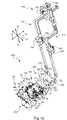
- FIG. 1is a perspective view of a system according to one embodiment of the invention, in which multiple level facet joint replacement may be carried out with adjacent level fusion.
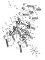
- FIG. 2is an exploded, perspective view of the caudal facet joint assembly, fixation members, and locking assemblies of the system of FIG. 1 .
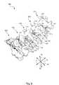
- FIG. 3is an exploded, perspective view of the caudal fusion assembly, fixation members, and yoke assemblies of the system of FIG. 1 .
- FIG. 4is an exploded, perspective view of the cephalad fusion assembly, fixation members, and yoke assemblies of the system of FIG. 1 .
- FIG. 5is a perspective view of a system according to one alternative embodiment of the invention, in which multiple level facet joint replacement may be carried out without adjacent level fusion.
- FIG. 6is a perspective view of one of the engagement members of the system of FIG. 5 .
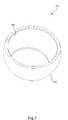
- FIG. 7is a perspective view of one of the in-growth cups of the system of FIG. 5 .
- FIG. 8is a perspective view of a portion of a spine to which the system of FIG. 1 or the system of FIG. 5 may be secured to provide multiple level facet joint replacement with or without adjacent level fusion.
- FIG. 9is a perspective view of the portion of the spine of FIG. 8 after resection of some of the natural articular surfaces of the vertebrae.
- FIG. 10is a perspective view of the portion of the spine of FIG. 8 after implantation of guide wires in the pedicles of some of the vertebrae.
- FIG. 11is a perspective view of the portion of the spine of FIG. 8 after reaming of the pedicle saddle points to provide semispherical resections.
- FIG. 12is a perspective view of the portion of the spine of FIG. 8 with a frame registered on the third vertebra to facilitate formation of shaped resections on the saddle points of the second vertebra.
- FIG. 13is a perspective view of the portion of the spine of FIG. 8 after attachment of the caudal fusion assembly and the superior prostheses of the caudal facet joint assembly of the system of FIG. 1 to the portion of the spine.
- FIG. 14is a perspective view of the portion of the spine of FIG. 8 with the frame registered on the fourth vertebra to facilitate formation of shaped resections on the saddle points of the third vertebra.
- FIG. 15is a perspective view of the portion of the spine of FIG. 8 after further attachment of the inferior prostheses of the caudal facet joint assembly and the superior prostheses of the cephalad facet joint assembly of the system of FIG. 1 to the portion of the spine.
- FIG. 16is a perspective view of the portion of the spine of FIG. 8 with the frame registered on the fifth vertebra to facilitate formation of shaped resections on the saddle points of the fourth vertebra.
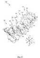
- FIG. 17is a perspective view of the portion of the spine of FIG. 8 after further attachment of the inferior prostheses of the cephalad facet joint assembly of FIG. 1 and a cephalad fusion assembly to the portion of the spine.
- FIG. 18is a perspective view of the portion of the spine of FIG. 8 with the system of FIG. 5 attached thereto instead of the system of FIG. 17 .
- the present inventionrelates to facet joint replacement implants that can be applied to multiple adjacent vertebral levels and/or used with adjacent-level fusion implants.
- the facet joint replacement implants and fusion implantsare independently orientable at each vertebral level to compensate for natural variations in spinal morphology.
- FIG. 1a perspective view illustrates a system 10 according to one embodiment of the invention, in which multiple level facet joint replacement may be carried out with adjacent level fusion.
- the directional arrows of FIG. 1illustrate how the system 10 would be oriented with respect to a human spine by illustrating a cephalad direction 12 , a caudal direction 14 , an anterior direction 16 , a posterior direction 18 , and a medial/lateral direction 20 .
- FIG. 10The configuration of the system 10 will be explained in the descriptions of FIGS. 1 through 4 , and the configuration of an alternative system without adjacent level fusion will be explained in the descriptions of FIG. 5 through 7 .
- One method of implanting the system 10 and securing it to a portion of a human spinewill be shown and described in connection with FIGS. 8 through 16 , and implantation of the alternative system will be set forth in the description of FIG. 18 .
- the system 10includes a caudal facet joint assembly 24 , a cephalad facet joint assembly 26 , a caudal fusion assembly 28 , and a cephalad fusion assembly 30 .
- Each of the facet joint assemblies 24 , 26provides replacement (i.e., arthroplasty) of the facet articular surfaces of one “facet joint,” which includes the two superior articular surfaces of one vertebra and the two inferior articular surfaces of a second vertebra superior to the first vertebra.
- the facet joint assemblies 24 , 26may substantially duplicate the shapes and orientations of the natural articular surfaces so that they provide natural, or “anatomic” articulation that feels to the patient like the natural motion of a healthy spinal joint.
- the caudal fusion assembly 28is designed to substantially immobilize one facet joint by substantially preventing relative motion between two vertebrae.
- the cephalad fusion assembly 30is designed to substantially immobilize two facet joints by substantially preventing relative motion between three vertebrae. If desired, the caudal fusion assembly 28 and/or the cephalad fusion assembly 30 may be used on combination with other implants such as intervertebral spacers, fusion cages, anterior plates to enhance the stability and/or fusion of the joints involved. The use of such implants is known in the art; accordingly, they are not described herein.
- the system 10may be applied to the sacrum and the lumbar vertebrae, such that the caudal fusion assembly 28 immobilizes the joint between S1 and L5, the caudal facet joint assembly 24 provides motion of the joint between L5 and L4, the cephalad facet joint assembly 26 provides motion of the joint between L4 and L3, and the cephalad fusion assembly immobilizes the joint between L3 and L2 and the joint between L2 and L1.
- the present inventionis not limited to lumbar/sacral applications, and the implants and techniques illustrated may be readily adapted by one of skill in the art for use with thoracic vertebrae, cervical vertebrae, and/or any combination of spinal vertebrae and the sacrum.
- the caudal facet joint assembly 24has a left superior prosthesis 34 , a right superior prosthesis 36 , a left inferior prosthesis 38 , and a right inferior prosthesis 40 .
- the superior prostheses 34 , 36are shaped to replace the superior articular surfaces of a vertebra
- the inferior prostheses 38 , 40are shaped to replace the inferior articular surfaces of an adjacent vertebra. Due to natural variations in vertebral articular processes, the superior prostheses 34 , 36 need not be mirror images of each other, and the inferior prostheses 38 , 40 also need not be mirror images of each other. Rather, each of the prostheses 34 , 36 , 38 , 40 of the caudal facet joint assembly 24 may be selected from a kit of differently-dimensioned prostheses designed for use with a wide variety of vertebral morphologies.
- the left and right inferior prostheses 38 , 40may be secured together through the use of a crosslink assembly 42 .
- the crosslink assembly 42substantially prevents relative motion between the left and right inferior prostheses 38 , 40 to ensure that they do not shift under the loads produced by articulation with the superior prostheses 34 , 36 .
- the crosslink assembly 42may be designed to be attachable in loose form to the inferior prostheses 38 , 40 so that the prostheses 38 , 40 can be reoriented prior to tightening of the crosslink assembly 42 to a rigid state.
- the cephalad facet joint assembly 26has a left superior prosthesis 44 , a right superior prosthesis 46 , a left inferior prosthesis 48 , and a right inferior prosthesis 50 .
- the inferior prostheses 48 , 50may be secured together through the use of a crosslink 52 .
- the prostheses 44 , 46 , 48 , 50 and the crosslink 52 of the cephalad facet joint assembly 26may be configured similarly to the prostheses 34 , 36 , 38 , 40 and the crosslink 42 of the caudal facet joint assembly 24 .
- the prostheses 44 , 46 , 48 , 50 and the crosslink 52need not be identical to the prostheses 34 , 36 , 38 , 40 and the crosslink 42 .
- the prostheses 34 , 36 , 38 , 40 , 44 , 46 , 48 , 50 of the caudal facet joint assembly 24 and the cephalad facet joint assembly 26may be secured to vertebrae through the use of fixation members, in the form of pedicle screws 54 , and locking assemblies 56 .
- the locking assemblies 56may be used to independently lock out rotational and translational motion of the prostheses 34 , 36 , 38 , 40 , 44 , 46 , 48 , 50 relative to the pedicle screws 54 .
- the inferior prostheses 38 , 40 of the caudal facet joint assembly 24may be shaped to nest within the superior prostheses 44 , 46 of the cephalad facet joint assembly 26 so that the inferior prostheses 38 , 40 and the superior prostheses 44 , 46 can be secured to the corresponding vertebra through the use of a single pair of pedicle screws 54 and locking assemblies 56 .
- the caudal fusion assembly 28may have a left superior prosthesis 60 , a right superior prosthesis 62 , and two rods 64 .
- the superior ends of the rods 64may be secured to the corresponding vertebra via the superior prostheses 60 , 62 .
- the inferior ends of the rods 64may be secured to the immediately inferior vertebra through the use of pedicle screws 66 and yoke assemblies 68 .
- the superior prostheses 60 , 62are shaped to nest within the superior prostheses 34 , 36 of the caudal facet joint assembly such that the superior prostheses 60 , 62 and the superior prostheses 34 , 36 can be secured to the corresponding vertebra with a single pair of pedicle screws 54 and locking assemblies 56 .
- the cephalad fusion assembly 30may have a left inferior prosthesis 72 , a right inferior prosthesis 74 , a pair of rods 76 , a pair of polyaxial rod connectors 78 , and a crosslink assembly 82 .
- the inferior ends of the rods 76may be secured to the corresponding vertebra via the inferior prostheses 72 , 74 .
- the central portions of the rods 76 and the superior ends of the rods 76may be secured to the two immediately superior vertebrae through the use of pedicle screws 66 and yoke assemblies 68 like those used in connection with the caudal fusion assembly 28 .
- the crosslink assemblyrigidly connects the rods 76 together to maintain the rigidity of the cephalad fusion assembly 30 .
- the inferior prostheses 48 , 50 of the cephalad facet joint assembly 26are shaped to nest within the inferior prostheses 72 , 74 of the cephalad fusion assembly 30 such that the inferior prostheses 48 , 50 and the inferior prostheses 72 , 74 can be secured to the corresponding vertebra with a single pair of pedicle screws 54 and locking assemblies 56 .
- each of the superior prostheses 34 , 36has a bone apposition surface 90 , a semispherical receiving surface 92 , and an articulation surface 94 .
- Each bone apposition surface 90is part of a mounting portion of the corresponding prosthesis 34 or 36 , and may be generally conical in shape, with protruding fingers designed to engage the vertebral bone to prevent relative motion between the superior prostheses 34 , 36 and the vertebra to which they are attached.
- Each semispherical receiving surface 92has a substantially concave, semispherical shape sized to receive the corresponding convex, semispherical portion of any of the superior prostheses 60 , 62 , the inferior prostheses 38 , 40 , or the inferior prostheses 48 , 50 .
- Each articulation surface 94has a shape that is shaped to articulate with the corresponding inferior prosthesis 38 or 40 .
- the articulation surfaces 94may mimic the shapes of the natural superior facets, and may thus have concave, trough-like shapes or the like.
- Each of the inferior prostheses 38 , 40may have a semispherical engagement surface 100 , a semispherical receiving surface 102 , an articulation surface 104 , and a stem 106 .
- the semispherical engagement surfaces 100have substantially convex, semispherical shapes sized to nest within the semispherical receiving surfaces 92 of the superior prostheses 34 , 36 .
- the semispherical shapes of the semispherical receiving surfaces 92 and semispherical engagement surfaces 100permit polyaxial adjustment of the orientation of each inferior prosthesis 38 , 40 relative to the corresponding superior prosthesis 34 , 36 .
- polyaxial adjustabilityrefers to the ability to rotate the object about at least two, and possibly three, orthogonal axes relative to another object.
- the facet joint assemblies 24 , 26are adjustable to accommodate a wide variety of spinal morphologies, and provide relatively natural articulation regardless of natural variations in vertebral geometry.
- the semispherical engagement surfaces 100may optionally be broken by slots, as shown in FIG. 2 .
- the slots in the semispherical engagement surfaces 100permit the semispherical engagement surfaces to contract as they are urged into the semispherical receiving surfaces 92 .
- the resulting expansion pressureholds the semispherical engagement and receiving surfaces 100 , 92 tightly together to restrict relative motion between the superior prostheses 34 , 36 and the inferior prostheses 38 , 40 after the locking assemblies 56 have been tightened on the pedicle screws 54 .
- the semispherical receiving surfaces 102 of the inferior prostheses 38 , 40have substantially concave, semispherical shapes that are substantially concentric with the semispherical engagement surfaces 100 .
- the semispherical receiving surfaces 102are sized to receive corresponding convex, semispherical surfaces of the locking assemblies 56 , as will be described in detail subsequently.
- the articulation surfaces 104are shaped to articulate with the articulation surfaces 94 of the superior prostheses 34 , 36 in a manner that substantially duplicates the articulation of the natural facet joint replaced by the superior and inferior prostheses 34 , 36 , 38 , 40 .
- the articulation surfaces 104may mimic the shapes of the natural inferior facets, and may have convex shapes.
- Each stem 106connects one of the semispherical engagement surfaces 100 with the corresponding articulation surface 104 such that, upon attachment of the inferior prostheses 38 , 40 to the pedicles of the corresponding vertebra, the articulation surfaces 104 are positioned at or near the locations of the removed natural inferior facets.
- the crosslink assembly 42includes two implant coupling components 110 , two bolts 112 , two rod coupling components 114 , two nuts 116 , and a rod 118 .
- the implant coupling components 110are shaped to be attached to the inferior prostheses 38 , 40 in a manner that permits adjustment of the positioning of the implant coupling components 110 relative to the inferior prostheses 38 , 40 along an axis extending generally anterior-posteriorly.
- the bolts 112can pass through holes in the implant coupling components 110 and through aligned holes in the rod coupling components 114 so that the rod coupling components 114 can be pivotably adjusted about the axes of the bolts 112 and locked in place relative to the implant coupling components 110 through the use of the nuts 116 .
- the bolts 112 and nuts 116are also used to secure the rod coupling components 114 to the ends of the rod 118 at the desired spacing.
- the crosslink assembly 42is adjustable to suit the spacing and angulation of the inferior prostheses 38 , 40 , and is also easily lockable through the use of the bolts 112 and nuts 116 to provide a rigid bridge between the inferior prostheses 38 , 40 .
- each of the pedicle screws 54has a proximal end 130 that receives the corresponding locking assembly 56 , and a distal end 132 with threads that facilitate implantation of the distal end 132 in the bone of the corresponding vertebra.
- Each proximal end 130has a sliding interface with a substantially continuous cross section, along which the corresponding locking assembly 56 can selectively slide.
- the sliding interfacesare polygonal portions 134 having octagonal cross sectional shapes. Other cross sectional shapes may, of course, be used to provide a sliding interface.
- Each proximal end 130also has threads 136 designed to receive the corresponding locking assembly 56 , and a torquing interface 138 that can be engaged by a tool to facilitate implantation of the pedicle screw 54 in the corresponding vertebra.
- Each of the locking assemblies 56includes an interpositional member 140 , an engagement member 142 , a rotational locking member 144 , and a translational locking member 146 .
- Each interpositional member 140has exterior threads, a flared end, and a bore shaped to slide along the polygonal portion 134 of the corresponding pedicle screw 54 .
- Each engagement member 142may take the form of a split sphere 142 with a plurality of slots that permit expansion and contraction of the split sphere 142 .
- Each split sphere 142has a hollow interior in which the corresponding interpositional member 140 may be positioned, such that the flared end of the interpositional member protrudes from the distal end of the split sphere 142 .
- Each of the rotational locking members 144includes interior threads that engage the exterior threads of the corresponding interpositional member 140 .
- the split sphere 142may be compressed between the rotational locking member 144 and the flared end of the attached interpositional member 140 .
- the flared endurges outward expansion of the split sphere 142 so that the outer surface of the split sphere 142 engages the semispherical receiving surface 102 of the corresponding inferior prosthesis 38 or 40 .
- Due to the slotted geometry of the semispherical engagement surface 100the resulting radial pressure on the semispherical receiving surface 102 causes expansion of the corresponding semispherical engagement surface 100 .
- the semispherical engagement surface 100expands to press against the semispherical receiving surface 92 of the corresponding superior prosthesis 34 or 36 .
- the translational locking member 146presses the remainder of the locking assembly 56 , the inferior prosthesis 38 or 40 , and the superior prosthesis 34 or 36 against the bony apposition surface of the corresponding vertebra to prevent further sliding of the locking assembly 56 , the inferior prosthesis 38 or 40 , and the superior prosthesis 34 , 36 relative to the pedicle screw 54 .
- each of the inferior prostheses 60 , 62has a semispherical engagement surface 150 , a semispherical receiving surface 152 , a yoke assembly 154 , and a stem 156 .
- Each semispherical engagement surface 150has a convex, substantially semispherical shape sized to nest within the semispherical receiving surface 92 of the corresponding superior prosthesis 34 or 36 .
- Each semispherical engagement surface 150may optionally have a slotted configuration like that of the semispherical engagement surfaces 100 of the inferior prostheses 38 , 40 shown in FIG. 2 . However, as embodied in FIG. 3 , the semispherical engagement surfaces 150 are not slotted.
- Each of the semispherical receiving surfaces 152has a concave, substantially semispherical shape sized to receive the outer surfaces of the split spheres 142 of the locking assemblies 56 in a manner similar to that of the semispherical receiving surfaces 102 of the inferior prostheses 38 , 40 .
- Each yoke assembly 154is shaped to receive the cephalad end of one of the rods 64 .
- the yoke assemblies 154are connected to the semispherical engagement surfaces 150 by the stems 156 .
- each of the pedicle screws 66is configured differently from the pedicle screws 54 because the pedicle screws 66 are designed to receive the yoke assemblies 68 instead of the locking assemblies 56 .
- each of the pedicle screws 66has a proximal end 158 and a distal end 160 .
- the proximal end 158may have a head (not visible) with a semispherical undercut that permits polyaxial rotation of the corresponding yoke assembly 68 relative to it, until the yoke assembly 68 is locked.
- Each distal end 160may be threaded to permit implantation in the pedicle of a vertebra.
- each of the yoke assemblies 68 , 154may have a configuration similar to that of known polyaxial yokes, or may be configured differently from known systems. As embodied in FIG. 3 , each yoke assembly 68 , 154 has a first wall 162 and a second wall 164 that extend generally parallel to each other to define a trough 166 that extends between the first and second walls 162 , 164 . Each of the first and second walls 162 , 164 has threads (not shown) on the interior, concave surface.
- Each yoke assembly 68 , 154may also have a nut 168 with exterior threads (not shown) that can be threadably engaged with the threads of the corresponding walls 162 , 164 to advance the nut 168 toward the trough 166 .
- the polyaxial adjustability of the yoke assemblies 68 prior to tightening of the nuts 168permits attachment of the caudal ends of the rods 64 to the pedicle screws 66 at a wide variety of relative orientations, thereby permitting the caudal fusion assembly with a wide variety of spinal morphologies.
- each of the inferior prostheses 72 , 74 of the cephalad fusion assembly 30has a bone apposition surface 180 , a semispherical receiving surface 182 , a polyaxial receiver 184 , and a receiver fastener 186 .
- the bone apposition surfaces 180are substantially the same as the bone apposition surfaces 90 of the superior prostheses 34 , 36 of the caudal facet joint assembly 24 .
- each of the bone apposition surfaces 180may be generally conical in shape, with protruding fingers designed to engage the vertebral bone to prevent relative motion between the inferior prostheses 72 , 74 and the vertebra to which they are attached.
- the semispherical receiving surfaces 182may be substantially the same as the semispherical receiving surfaces 92 of the superior prostheses 34 , 36 of the caudal facet joint assembly. Thus, each of the semispherical receiving surfaces 182 may have a substantially concave, semispherical shape sized to receive the corresponding convex, semispherical portion of any of the superior prostheses 60 , 62 , the inferior prostheses 38 , 40 , or the inferior prostheses 48 , 50 .
- Each of the rod connectors 78may have a substantially semispherical shape with slots that permit expansion or contraction of the rod connectors 78 .
- the rod connectors 78may have bores (not visible) sized to receive the caudal ends of the rods 76 .
- the exterior surfaces of the rod connectors 78may be compressed to substantially radially compress the caudal ends of the rods 76 , thereby providing a tight attachment between the rod connectors 78 and the caudal ends of the rods 76 .
- Each of the polyaxial receivers 184extends form the corresponding bone apposition surface 180 and has a concave, semispherical bore (not visible) shaped to receive the corresponding polyaxial rod connector 78 in a manner that permits polyaxial rotation between the rod connector 78 and the polyaxial receiver 184 .
- each polyaxial receiver 184can receive the caudal end of the corresponding rod 76 at any of a plurality of relative orientations. This permits usage of the cephalad fusion assembly 30 with a wide variety of spinal morphologies.
- the receiver fasteners 186are used to tighten the concave, semispherical bores of the polyaxial receivers 184 around the rod connectors 78 .
- the receiver fasteners 186may take the form of small screws that can be tightened to cause contraction of the concave, semispherical bores of the polyaxial receivers 184 around the rod connectors 78 .
- the rod connectors 78tighten around the caudal ends of the rods 76 so that the rods 76 become rigidly secured to the inferior prostheses 72 , 74 .
- the pedicle screws 66 and yoke assemblies 68are identical to those described in connection with FIG. 3 . Accordingly, the yoke assemblies 68 are polyaxially rotatable relative to the pedicle screws 66 to permit them to receive the cephalad ends of the rods 76 at any of a plurality of relative orientations. Like those of FIG. 3 , the orientations of the yoke assemblies 68 may also be locked relative to the pedicle screws 66 by tightening the nuts 168 against the cephalad ends of the rods 76 .
- the crosslink assembly 82is very similar to the crosslink assemblies 42 , 52 of the facet joint assemblies 24 , 26 . Accordingly, the crosslink assembly 82 has two rod coupling components 190 , two bolts 112 , two rod coupling components 114 , two nuts 116 , and a rod 118 .
- the rod coupling components 190may be very similar to the implant coupling components 110 of the crosslink assemblies 42 , 52 , except that the rod coupling components 190 are sized to grip the rods 76 of the caudal fusion assembly 28 instead of the inferior prostheses 38 , 40 .
- the bolts 112 , 114 , nuts 116 , and rod 118function in a manner very similar to that described in connection with FIG. 2 , in the description of the crosslink assembly 42 of the caudal facet joint assembly 24 .
- the crosslink 82may be adjusted to accommodate different positions of the rods 76 , and may then be tightened to provide a rigid bridge between the rods 76 .
- the system 10 of FIG. 1effectively replaces the natural facets of two spinal motion segments with prosthetic facets, fuses the motion segment immediately inferior to the prosthetic facets, and also fuses the two motion segments immediately superior to the prosthetic facets.
- the system 10is modular in design, and can therefore be used for any combination of facet joint replacement and fusion, whether one or multiple motion segments are to receive facet joint replacement or fusion, and whether or not the motion segments to be treated are adjacent to each other.
- FIG. 5a perspective view illustrates a system 210 according to one alternative embodiment of the invention, in which multiple level facet joint replacement may be carried out without adjacent level fusion.
- the system 210includes the caudal facet joint assembly 24 and the cephalad facet joint assembly 26 of FIG. 1 .
- the caudal fusion assembly 28 and the cephalad fusion assembly 30have been omitted.
- locking assemblies 240are provided in place of the caudal locking assemblies 56 of the caudal facet joint assembly 24 . Since the caudal fusion assembly 28 is not present, the superior prostheses 60 , 62 of the caudal fusion assembly 28 are not nested within the semispherical receiving surfaces 92 of the superior implants 34 , 36 of the caudal facet joint assembly 24 . To fill the space that would otherwise be taken by the superior prostheses 60 , 62 , the locking assemblies 240 include engagement members 242 that take the place of the split spheres 142 included in the locking assemblies 56 . The engagement members 242 are larger than the split spheres 142 and will be shown and described in connection with FIG. 6 .
- the inferior prostheses 72 , 74 of the cephalad fusion assembly 30also are not present.
- in-growth cups 272may be provided. The in-growth cups receive the semispherical engagement surfaces 100 of the inferior prostheses 48 , 50 of the cephalad fusion assembly 26 in a manner similar to that of the inferior prostheses 72 , 74 , as will be described in connection with FIG. 7 .
- the remaining components of the system 210are substantially the same as those of the system 10 . Accordingly, a kit can easily be provided, including the facet joint assemblies 24 , 26 , fusion assemblies 28 , 30 , pedicle screws 54 , 66 , locking assemblies 56 , yoke assemblies 68 , engagement members 242 , and in-growth cups 272 . Such a kit would enable the surgeon to select the components needed for either of the systems 10 , 210 , thereby providing maximum flexibility and minimizing inventory.
- a perspective viewillustrates one of the engagement members 242 of the system 210 of FIG. 5 .
- the engagement member 242has an interior surface 282 with a generally cylindrical shape broken by slots 284 .
- the engagement member 242also has a proximal shoulder 286 and a distal shoulder 288 .
- the proximal shoulder 286 of the engagement member 242may receive pressure from the associated rotational locking member 144 to urge the distal shoulder 288 to slide over the flared portion of the corresponding interpositional member 140 , thereby causing expansion of the distal portion of the engagement member 242 .
- the outer surface of the engagement member 242then presses directly against the semispherical receiving surface 92 of the corresponding superior prosthesis 34 or 36 of the caudal facet joint assembly 24 .
- the larger size of the engagement members 242 relative to the split spheres 142enables the locking assemblies 240 to operate in a manner similar to that of the locking assemblies 56 , without requiring the presence of the superior prostheses 60 , 62 of the caudal fusion assembly 28 .
- FIG. 7a perspective view illustrates one of the in-growth cups 272 of the system 210 of FIG. 5 .
- the in-growth cup 272has a bone apposition surface 290 and a semispherical receiving surface 292 .
- the bone apposition surface 290may be semispherical as illustrated in FIG. 7 , or may be shaped differently.
- an in-growth cup(not shown) may have a bone apposition surface with a generally conical shape, with or without the fingers utilized by the bone apposition surfaces 90 of the superior prostheses 34 , 36 , 44 , 46 .
- the bone apposition surface 290may also be porous and/or textured to facilitate bone in-growth into the in-growth cup 272 .
- the semispherical receiving surface 292may be shaped substantially the same as the semispherical receiving surfaces 92 of the superior prostheses 34 , 36 , 44 , 46 . Accordingly, the semispherical receiving surface 292 may be sized to receive the corresponding convex, semispherical portion of any of the superior prostheses 60 , 62 , the inferior prostheses 38 , 40 , or the inferior prostheses 48 , 50 .
- the in-growth cups 272fill the spaces left by the omission of the inferior prostheses 72 , 74 of the cephalad fusion assembly 30 .
- FIGS. 8 through 17illustrate one procedure by which a system similar to the system 10 of FIG. 1 may be implanted.
- the system to be shown in FIG. 8 through 17provides facet joint replacement for two adjacent spinal motion segments, and fusion for the motion segments immediately inferior and superior to them.
- a perspective viewillustrates a portion of a spine 300 to which the system 10 of FIG. 1 or the system 210 of FIG. 5 may be secured to provide multiple level facet joint replacement with or without adjacent level fusion.
- the spine 300includes a first vertebra 302 , a second vertebra 304 , a third vertebra 306 , a fourth vertebra 308 , and a fifth vertebra 310 .
- the vertebrae 302 , 304 , 306 , 308 , 310may represent S1, L5, L4, L3, and L2, respectively.
- the vertebrae 302 , 304 , 306 , 308 , 310may represent other vertebrae of the spine 300 .
- the vertebrae 302 , 304 , 306 , 308 , 310have many anatomical structures known to those of skill in the art. These anatomical structures include pedicles 314 of the second vertebra 304 , pedicles 316 of the third vertebra 306 , pedicles 318 of the fourth vertebra 308 , and pedicles 320 of the fifth vertebra 310 .
- the articular processes of the vertebrae 304 , 306 , 308 , 310may first be resected.
- the articular processes providing the joints between the second and third vertebrae 304 , 306 and between the third and fourth vertebrae 306 , 308are resected to enable their prosthetic counterparts to be positioned in such a manner that substantially natural articulation is provided.
- the articular processes providing the joints between the first and second vertebrae 302 , 304 and between the fourth and fifth vertebrae 308 , 310may be left intact because they may not interfere with implantation of the fusion components.
- the articular processes providing the joints between the first and second vertebrae 302 , 304 and/or between the fourth and fifth vertebrae 308 , 310may be resected to facilitate implantation of the fusion components and/or to remove diseased or brittle bone.
- a perspective viewillustrates the portion of the spine 300 of FIG. 8 after resection of some of the natural articular surfaces of the vertebrae 304 , 306 , 308 , 310 .
- the superior and inferior articular processes of the second vertebra 304have been resected away, leaving two inferior resections 330 and two superior resections 332 .
- the superior and inferior articular processes of the third vertebra 306have been resected away, leaving two inferior resections 334 and two superior resections 336 .
- the superior and inferior articular processes of the fourth vertebra 308have been resected away, leaving two inferior resections 338 and two superior resections 340 .
- the inferior articular processes of the fifth vertebra 310have been resected away, leaving two inferior resections 342 .
- the resections 330 , 332 , 334 , 336 , 338 , 340 , 342need not be made at any precise angle or location.
- guide wiresmay be implanted in the vertebrae 304 , 306 , 308 , 310 .
- the guide wiresmay be used to guide further steps.
- a perspective viewillustrates the portion of the spine 300 of FIG. 8 after implantation of guide wires 350 in the pedicles 314 , 316 , 318 , 320 of the second, third, fourth, and fifth vertebrae 304 , 306 , 308 , 310 .
- the guide wires 350may be configured and implanted in a variety of ways, many of which are known in the art. Each guide wire 350 is implanted along the axis of one of the pedicles 314 , 316 , 318 , 320 .
- first vertebra 302is S1
- guide wires 350may not be needed in the first vertebra 302 to locate sufficient bone mass for anchoring the caudal fusion assembly 28 to the first vertebra 302 .
- the saddle points of the pedicles 314 , 316 , 318 , 320 of the second, third, fourth, and fifth vertebrae 304 , 306 , 308 , 310may be reamed to provide semispherical resections.
- a perspective viewillustrates the portion of the spine 300 of FIG. 8 after reaming of the saddle points of the pedicles 314 , 316 , 318 , 320 to provide semispherical resections 354 , 356 , 358 , 360 .
- the second vertebra 304has semispherical resections 354
- the third vertebra 306has semispherical resections 356
- the fourth vertebra 308has semispherical resections 358
- the fifth vertebra 310has semispherical resections 360 .
- the semispherical resections 354 on the second vertebra 304are optional, and may be omitted if desired.
- Reamingmay be accomplished through the use of a reamer (not shown) with a rotating, semispherical head having a longitudinal bore designed to receive the protruding proximal ends of each of the guide wires 350 .
- the guide wires 350guide the reaming operations to ensure that the semispherical resections 354 , 356 , 358 , 360 have the proper shape and size.
- the saddle points of the pedicles 314 of the second vertebra 304may be further reamed and prepared to receive the superior prostheses 34 , 36 of the caudal facet joint assembly 24 .
- a perspective viewillustrates the portion of the spine 300 of FIG. 8 with a frame 370 registered on the third vertebra 306 to facilitate formation of shaped resections on the saddle points of the pedicles 314 second vertebra 304 .
- the frame 370has a first anchor 372 , a second anchor 374 , a first arm 376 , a second arm 378 , a locking mechanism 380 , and an external anchoring feature 382 .
- the anchors 372 , 374have semispherical distal ends designed to fit into the semispherical resections 356 of the third vertebra 306 in such a manner that the frame 370 can be oriented within the sagittal plane (not shown) to position it substantially perpendicular to the spine 300 .
- the first anchor 372attached to the distal end of the first arm 376
- the second anchor 374is attached to the distal end of the second arm 378 .
- the frame 370permits relative translation between the first and second arms 376 , 378 along three perpendicular axes. Relative motion of the arms 376 , 368 along all three axes may be locked through the use of a locking mechanism 380 .
- the external anchoring feature 382may be used to secure the frame 370 to a stationary object such as an operating table.
- An articulating, lockable arm (not shown) or the likemay be used to grip the substantially semispherical external anchoring feature 382 to keep the frame 370 at its desired position and orientation.
- the surgeonmay position the anchors 372 , 374 at the semispherical resections 356 and then rotate the frame 370 to the desired orientation while moving the arms 376 , 378 as needed relative to each other to keep the anchors 372 , 374 on the semispherical resections 356 .
- the surgeonmay actuate the locking mechanism 380 to lock the positions of the arms 376 , 378 relative to each other and secure the external anchoring feature to the stationary object to keep the frame 370 in the desired orientation.
- the first arm 376has a first registration feature designed to receive one or more tools such as resection tools.
- the first registration featuretakes the form of a first receiver 384 with a substantially rectangular bore.
- the second arm 378has a second receiver 386 with a substantially rectangular bore.
- the substantially rectangular bores of the receivers 384 , 386are designed to receive corresponding protruding anchoring features of the tools, and to retain the anchoring features in response to actuation of clips 388 on the receivers 384 , 386 .
- the clips 388may compress the substantially rectangular bores to cause the receivers 384 , 386 to securely retain the protruding anchoring features of the tools.
- a reamer with hollow reaming headmay be secured to each of the receivers 384 , 386 and used to further ream the saddle points of the pedicles 314 of the second vertebra 304 .
- the hollow reaming headmay engage the protruding proximal ends of the guide wires 350 attached to the second vertebra 304 , and may have a generally conical reaming surface that forms shaped resections 394 in the second vertebra 304 , as shown.
- the shaped resections 394may also have smaller holes for receiving the fingers of the bone apposition surfaces 90 of the superior prostheses 34 , 36 of the caudal facet joint assembly 24 .
- the smaller holesmay be formed through the use of a smaller reamer (not shown) applied through the openings of a template (not shown), or the like.
- FIG. 13a perspective view illustrates the portion of the spine 300 of FIG. 8 after attachment of the caudal fusion assembly 28 and the superior prostheses 34 , 36 of the caudal facet joint assembly 24 of the system of FIG. 1 to the first and second vertebrae 302 , 304 . More precisely, the guide wires 350 are removed and the pedicle screws 54 are implanted in the pedicles 314 of the second vertebra 304 , along the bores that remain after removal of the guide wires 350 . The superior prostheses 34 , 36 are positioned on the second vertebra 304 such that the fingers of the bone apposition surfaces 90 engage the small holes of the shaped resections 394 .
- the pedicle screws 66are implanted in the first vertebra 302 . If the first vertebra 302 is S1, implantation of the pedicle screws 66 is not in a pedicle, but is carried out in a portion of the sacrum with sufficient bone mass to provide anchorage. This may be accomplished through the use of any of a number of methods known in the art.
- the pedicle screws 66are implanted with the yoke assemblies 68 in place on the proximal ends 158 of the pedicle screws 66 .
- the superior prostheses 60 , 62 of the caudal fusion assembly 28are then positioned such that the semispherical engagement surfaces 150 of the superior prostheses 60 , 62 rest within the semispherical receiving surfaces 92 of the superior prostheses 34 , 36 .
- the yoke assemblies 68 , 154are then polyaxially rotatable relative to the first and second vertebrae 302 , 304 , respectively.
- the yoke assemblies 68 , 154are rotated to the optimal orientations for receiving the rods 64 , and the rods 64 are positioned in the troughs 166 of the yoke assemblies 68 , 154 .
- the nuts 168are threaded into engagement with their associated arms 162 , 164 and tightened to keep the rod 64 in place and restrain further pivoting of the yoke assemblies 68 , 154 .
- the interpositional members 140 , the split spheres 142 , and the rotational locking members 144are inserted on the distal ends 132 of each of the pedicle screws 54 and tightened to restrict rotation of the superior prostheses 60 , 62 relative to the pedicle screws 54 .
- the translational locking members 146are then inserted on the distal ends 132 of the pedicle screws 54 and tightened to restrict sliding of the superior prostheses 34 , 36 , 60 , 62 away from the second vertebra 304 .
- FIG. 14a perspective view illustrates the portion of the spine 300 of FIG. 8 with the frame 370 registered on the fourth vertebra 308 to facilitate formation of shaped resections 396 on the saddle points of the third vertebra 306 .
- the frame 370is seated on the fourth vertebra 308 such that the anchors 372 , 374 rest on the semispherical resections 358 .
- the frame 370is used in substantially the same manner set forth in the description of FIG. 12 , except that the shaped resections 396 are formed on the saddle points of the third vertebra 306 instead of those of the second vertebra 304 .
- the third vertebra 306is prepared to receive the superior prostheses 44 , 46 .
- the superior prostheses 44 , 46 of the cephalad facet joint assembly 26 and the inferior prostheses 38 , 40 of the caudal facet joint assembly 24may be secured to the third vertebra 306 .
- FIG. 15a perspective view illustrates the portion of the spine 300 of FIG. 8 after further attachment of the inferior prostheses 38 , 40 of the caudal facet joint assembly 24 , the crosslink assembly 42 , and the superior prostheses 44 , 46 of the cephalad facet joint assembly 26 of the system 10 of FIG. 1 to the portion of the spine 300 .
- the guide wires 350are removed and the pedicle screws 54 are implanted in the pedicles 316 of the third vertebra 306 , along the bores that remain after removal of the guide wires 350 .
- the superior prostheses 44 , 46are positioned on the third vertebra 306 such that the fingers of the bone apposition surfaces 90 engage the small holes of the shaped resections 396 .
- the inferior prostheses 38 , 40 of the caudal facet joint assembly 24are then positioned such that the semispherical engagement surfaces 100 of the inferior prostheses 38 , 40 rest within the semispherical receiving surfaces 92 of the superior prostheses 44 , 46 .
- the inferior prostheses 38 , 40remain polyaxially rotatable relative to the superior prostheses 44 , 46 .
- the crosslink assembly 42may then be loosely coupled to the inferior prostheses 38 , 40 . If desired, the crosslink assembly 42 may be loosely assembled before it is coupled to the inferior prostheses 38 , 40 . More precisely, the bolts 112 may be inserted through the implant coupling components 110 and the rod coupling components 114 , and the nuts 116 may be loosely threaded onto the bolts 112 . The ends of the rod 118 may be inserted into the rod coupling components. Then, the loosely assembled crosslink assembly 42 may be positioned and the implant coupling components 110 may be coupled to the inferior prostheses 38 , 40 .
- the crosslink assembly 42has not yet been tightened, and is therefore relatively freely configurable.
- the inferior prostheses 38 , 40may be rotated, with the crosslink assembly 42 coupled thereto, such that their articulation surfaces 104 are positioned to articulate optimally with the articulation surfaces 94 of the superior prostheses 34 , 36 of the caudal facet joint assembly 24 .
- the nuts 116may be tightened on the bolts 112 to lock the configuration of the crosslink assembly 42 , thereby providing a rigid bridge between the inferior prostheses 38 , 40 .
- the locking assemblies 56may be used to restrict further rotation or translation of the inferior prostheses 38 , 40 and the superior prostheses 44 , 46 , as described previously, in connection with FIG. 13 .
- the prostheses 38 , 40 , 44 , 46 and the crosslink assembly 42are rigidly and securely attached to the third vertebra 306 .
- the saddle points of the fourth vertebra 308may then be further resected to prepare the fourth vertebra 308 to receive the inferior prostheses 72 , 74 and the inferior prostheses 48 , 50 of the cephalad facet joint assembly 26 .
- FIG. 16a perspective view illustrates the portion of the spine 300 of FIG. 8 with the frame 370 registered on the fifth vertebra 310 to facilitate formation of shaped resections 398 on the saddle points of the fourth vertebra 308 .
- the frame 370is seated on the fifth vertebra 310 such that the anchors 372 , 374 rest on the semispherical resections 360 .
- the frame 370is used in substantially the same manner set forth in the description of FIG. 12 , except that the shaped resections 398 are formed on the saddle points of the fourth vertebra 308 instead of those of the second vertebra 304 .
- the fourth vertebra 308is prepared to receive the inferior prostheses 72 , 74 .
- the inferior prostheses 72 , 74 and the inferior prostheses 48 , 50 of the cephalad facet joint assembly 26may be secured to the fourth vertebra 308 .
- FIG. 17a perspective view illustrates the portion of the spine 300 of FIG. 8 after further attachment of the inferior prostheses 72 , 74 and the inferior prostheses 48 , 50 of the cephalad facet joint assembly 26 to the portion of the spine 300 .
- a complete system 410has been attached to the vertebrae 302 , 304 , 306 , 308 , 310 .
- the system 410is similar to the system 10 of FIG. 1 , except that the system 410 fuses only one, and not two, levels cephalad to the cephalad facet joint assembly 26 . Accordingly, in place of the cephalad fusion assembly 30 of FIG.
- cephalad fusion assembly 430that provides fusion for just one motion segment.
- cephalad fusion assembly 430has rods 476 that may be somewhat shorter than the rods 76 of the cephalad fusion assembly 30 of FIG. 1 .
- the guide wires 350are first removed from the pedicles 318 of the fourth vertebra 308 and the pedicle screws 54 are implanted in the pedicles 318 of the fourth vertebra 308 , along the bores that remain after removal of the guide wires 350 .
- the inferior prostheses 72 , 74are positioned on the fourth vertebra 308 such that the fingers of the bone apposition surfaces 180 engage the small holes of the shaped resections 398 .
- the inferior prostheses 48 , 50 of the cephalad facet joint assembly 26are then positioned such that the semispherical engagement surfaces 100 of the inferior prostheses 48 , 50 rest within the semispherical receiving surfaces 182 of the inferior prostheses 72 , 74 .
- the inferior prostheses 48 , 50remain polyaxially rotatable relative to the inferior prostheses 72 , 74 .
- the crosslink assembly 52may then be loosely coupled to the inferior prostheses 48 , 50 . If desired, the crosslink assembly 52 may be loosely assembled before it is coupled to the inferior prostheses 48 , 50 . More precisely, the procedure set forth in the description of FIG. 15 , for assembly of the crosslink assembly 42 , may also be used for the crosslink assembly 52 .
- the inferior prostheses 48 , 50may be rotated, with the crosslink assembly 52 coupled thereto, such that their articulation surfaces 104 are positioned to articulate optimally with the articulation surfaces 94 of the superior prostheses 44 , 46 of the cephalad facet joint assembly 26 . Once the articulation surfaces 104 have reached the proper positions, the crosslink 52 may be tightened to provide a rigid bridge between the inferior prostheses 48 , 50 .
- the locking assemblies 56may be used to restrict further rotation or translation of the inferior prostheses 48 , 50 and the inferior prostheses 72 , 74 , as described previously, in connection with FIG. 13 .
- the prostheses 48 , 50 , 72 , 74 and the crosslink assembly 52are rigidly and securely attached to the fourth vertebra 308 .
- the pedicle screws 66are implanted in the pedicles 320 of the fifth vertebra 310 . This may be accomplished by removing the guide wires 350 and inserting the distal ends 160 of the pedicle screws 66 into the pedicles 320 through the bores left by removal of the guide wires 350 .
- the pedicle screws 66are implanted with the yoke assemblies 68 in place on the proximal ends 158 of the pedicle screws 66 .
- the polyaxial rod connectors 78may be installed in the semispherical bores of the polyaxial receivers 184 of the inferior prostheses 72 , 74 by the manufacturer of the system 410 , or by the surgeon. Thus, if the polyaxial rod connectors 78 are not already in the semispherical bores of the polyaxial receivers 184 , they may now be inserted therein. The caudal ends of the rods 476 may be inserted into the bores of the polyaxial rod connectors 78 . The polyaxial rod connectors 78 swivel within the polyaxial receivers 184 such that the cephalad ends of the rods 476 can be placed in the troughs 166 of the yoke assemblies 68 .
- the yoke assemblies 68are also polyaxially rotatable relative to the pedicle screws 66 , and may thus be reoriented to receive the cephalad ends of the rods 476 at the optimal angles.
- the nuts 168may be rotated into engagement with the walls 162 , 164 of the yoke assemblies 68 and tightened to secure the cephalad ends of the rods 476 to the yoke assemblies 68 , and to restrict further rotation of the yoke assemblies 68 relative to the pedicle screws.
- the receiver fasteners 186may also be tightened to restrict further rotation of the polyaxial rod connectors 78 and the caudal ends of the rods 476 relative to the inferior prostheses 72 , 74 .
- Facet joint replacement for the joints between the second and third vertebrae 304 , 306 and between the third and fourth vertebrae 306 , 308is now complete. Additionally, fusion of the joint between the fourth and fifth vertebrae 308 , 310 and fusion of the joint between the first and second vertebrae 302 , 304 have also been completed. Thus, implantation of the system 410 is complete, and the surgical wound site may be closed.
- FIG. 18a perspective view illustrates the portion of the spine 300 of FIG. 8 with the system 210 of FIG. 5 attached thereto instead of the system 410 of FIG. 17 .
- the fusion assemblies 28 , 30have been omitted, and the engagement members 242 and in-growth cups 272 of FIGS. 6 and 7 , respectively, have been included to compensate for the omission.
- the caudal and cephalad facet joint assemblies 24 , 26have been secured to the second, third, and fourth vertebrae 304 , 306 , 308 to provide facet joint replacement for the joints between the second and third vertebrae 304 , 306 and between the third and fourth vertebrae 306 , 308 .
- No fusionhas been carried out.
- natural articulationmay continue in the joint between the fourth and fifth vertebrae 308 , 310 and in the joint between the first and second vertebrae 302 , 304 .
- the systems 10 , 210 , 410are merely exemplary, and that many different systems may be envisioned with the aid of the present disclosure, incorporating facet joint replacement of one or more motion segments with or without fusion.
- the present inventionalso opens new possibilities for revision.
- the system 210 of FIG. 18may be revised to provide caudal and/or cephalad adjacent-level fusion by removing the engagement members 242 and/or the in-growth cups 272 , and replacing them with the caudal fusion assembly 28 and the split spheres 142 and/or with one of the cephalad fusion assemblies 30 , 430 .
- facet joint replacement hardwaresuch as the facet joint assemblies 24 , 26 may be used to replace existing fusion assemblies such as the fusion assemblies 28 , 30 , or fusion assemblies currently in use in orthopedics.
- facet joint replacement assemblies 24 , 26may be replaced with fusion hardware such as the fusion assemblies 28 , 30 .
- Additional levels of fusion or facet joint replacementmay be added to a system of any configuration according to the invention.
- the pedicle screws 54 and 66do not require bone cement, and may thus be relatively freely removable from the vertebrae 302 , 304 , 306 , 308 , 310 in the event that a reversal of a facet joint replacement or fusion procedure is desired.
Landscapes
- Health & Medical Sciences (AREA)
- Orthopedic Medicine & Surgery (AREA)
- Life Sciences & Earth Sciences (AREA)
- Surgery (AREA)
- Neurology (AREA)
- Engineering & Computer Science (AREA)
- Biomedical Technology (AREA)
- General Health & Medical Sciences (AREA)
- Veterinary Medicine (AREA)
- Heart & Thoracic Surgery (AREA)
- Public Health (AREA)
- Animal Behavior & Ethology (AREA)
- Molecular Biology (AREA)
- Medical Informatics (AREA)
- Nuclear Medicine, Radiotherapy & Molecular Imaging (AREA)
- Oral & Maxillofacial Surgery (AREA)
- Cardiology (AREA)
- Transplantation (AREA)
- Vascular Medicine (AREA)
- Dentistry (AREA)
- Prostheses (AREA)
- Surgical Instruments (AREA)
Abstract
Description
Claims (11)
Priority Applications (9)
| Application Number | Priority Date | Filing Date | Title |
|---|---|---|---|
| US11/463,513US8562649B2 (en) | 2004-02-17 | 2006-08-09 | System and method for multiple level facet joint arthroplasty and fusion |
| PCT/US2007/060218WO2007084810A2 (en) | 2006-01-19 | 2007-01-08 | System and method for multiple level facet joint arthroplasty and fusion |
| EP07709987.7AEP1973484B1 (en) | 2006-01-09 | 2007-01-08 | System for multiple level facet joint arthroplasty and fusion |
| AU2007206072AAU2007206072A1 (en) | 2006-01-19 | 2007-01-08 | System and method for multiple level facet joint arthroplasty and fusion |
| JP2008551494AJP5140002B2 (en) | 2006-01-19 | 2007-01-08 | System and method for articulating and securing multi-level facet joints |
| CA002636676ACA2636676A1 (en) | 2006-01-09 | 2007-01-08 | System and method for multiple level facet joint arthroplasty and fusion |
| US12/240,512US8777994B2 (en) | 2004-06-02 | 2008-09-29 | System and method for multiple level facet joint arthroplasty and fusion |
| US14/291,297US9439688B2 (en) | 2004-06-02 | 2014-05-30 | System and method for multiple level facet joint arthroplasty and fusion |
| US15/236,962US9877748B2 (en) | 2004-06-02 | 2016-08-15 | System and method for multiple level facet joint arthroplasty and fusion |
Applications Claiming Priority (5)
| Application Number | Priority Date | Filing Date | Title |
|---|---|---|---|
| US54509404P | 2004-02-17 | 2004-02-17 | |
| US54510104P | 2004-02-17 | 2004-02-17 | |
| US10/860,778US7588590B2 (en) | 2003-12-10 | 2004-06-02 | Spinal facet implant with spherical implant apposition surface and bone bed and methods of use |
| US76086306P | 2006-01-19 | 2006-01-19 | |
| US11/463,513US8562649B2 (en) | 2004-02-17 | 2006-08-09 | System and method for multiple level facet joint arthroplasty and fusion |
Related Parent Applications (2)
| Application Number | Title | Priority Date | Filing Date |
|---|---|---|---|
| US10687856Continuation-In-Part | 2003-10-17 | ||
| US10/860,778Continuation-In-PartUS7588590B2 (en) | 2003-12-10 | 2004-06-02 | Spinal facet implant with spherical implant apposition surface and bone bed and methods of use |
Related Child Applications (1)
| Application Number | Title | Priority Date | Filing Date |
|---|---|---|---|
| US12/240,512DivisionUS8777994B2 (en) | 2004-06-02 | 2008-09-29 | System and method for multiple level facet joint arthroplasty and fusion |
Publications (2)
| Publication Number | Publication Date |
|---|---|
| US20070167946A1 US20070167946A1 (en) | 2007-07-19 |
| US8562649B2true US8562649B2 (en) | 2013-10-22 |
Family
ID=38264220
Family Applications (4)
| Application Number | Title | Priority Date | Filing Date |
|---|---|---|---|
| US11/463,513Active2027-01-23US8562649B2 (en) | 2004-02-17 | 2006-08-09 | System and method for multiple level facet joint arthroplasty and fusion |
| US12/240,512Active2026-07-14US8777994B2 (en) | 2004-06-02 | 2008-09-29 | System and method for multiple level facet joint arthroplasty and fusion |
| US14/291,297ActiveUS9439688B2 (en) | 2004-06-02 | 2014-05-30 | System and method for multiple level facet joint arthroplasty and fusion |
| US15/236,962ActiveUS9877748B2 (en) | 2004-06-02 | 2016-08-15 | System and method for multiple level facet joint arthroplasty and fusion |
Family Applications After (3)
| Application Number | Title | Priority Date | Filing Date |
|---|---|---|---|
| US12/240,512Active2026-07-14US8777994B2 (en) | 2004-06-02 | 2008-09-29 | System and method for multiple level facet joint arthroplasty and fusion |
| US14/291,297ActiveUS9439688B2 (en) | 2004-06-02 | 2014-05-30 | System and method for multiple level facet joint arthroplasty and fusion |
| US15/236,962ActiveUS9877748B2 (en) | 2004-06-02 | 2016-08-15 | System and method for multiple level facet joint arthroplasty and fusion |
Country Status (4)
| Country | Link |
|---|---|
| US (4) | US8562649B2 (en) |
| JP (1) | JP5140002B2 (en) |
| AU (1) | AU2007206072A1 (en) |
| WO (1) | WO2007084810A2 (en) |
Cited By (2)
| Publication number | Priority date | Publication date | Assignee | Title |
|---|---|---|---|---|
| US20170119537A1 (en)* | 2015-05-13 | 2017-05-04 | Gil Tepper | Three column spinal fixation implants and associated surgical methods |
| US10413333B2 (en)* | 2016-10-05 | 2019-09-17 | Spinefrontier, Inc | System and method for spinal fixation via a trans-facet pedicle screw assembly |
Families Citing this family (218)
| Publication number | Priority date | Publication date | Assignee | Title |
|---|---|---|---|---|
| US7833250B2 (en) | 2004-11-10 | 2010-11-16 | Jackson Roger P | Polyaxial bone screw with helically wound capture connection |
| US10258382B2 (en)* | 2007-01-18 | 2019-04-16 | Roger P. Jackson | Rod-cord dynamic connection assemblies with slidable bone anchor attachment members along the cord |
| US8353932B2 (en)* | 2005-09-30 | 2013-01-15 | Jackson Roger P | Polyaxial bone anchor assembly with one-piece closure, pressure insert and plastic elongate member |
| US8292926B2 (en) | 2005-09-30 | 2012-10-23 | Jackson Roger P | Dynamic stabilization connecting member with elastic core and outer sleeve |
| US10729469B2 (en) | 2006-01-09 | 2020-08-04 | Roger P. Jackson | Flexible spinal stabilization assembly with spacer having off-axis core member |
| US7862587B2 (en) | 2004-02-27 | 2011-01-04 | Jackson Roger P | Dynamic stabilization assemblies, tool set and method |
| WO2006052796A2 (en) | 2004-11-10 | 2006-05-18 | Jackson Roger P | Helical guide and advancement flange with break-off extensions |
| US8876868B2 (en) | 2002-09-06 | 2014-11-04 | Roger P. Jackson | Helical guide and advancement flange with radially loaded lip |
| US7621918B2 (en) | 2004-11-23 | 2009-11-24 | Jackson Roger P | Spinal fixation tool set and method |
| US6716214B1 (en)* | 2003-06-18 | 2004-04-06 | Roger P. Jackson | Polyaxial bone screw with spline capture connection |
| US7377923B2 (en) | 2003-05-22 | 2008-05-27 | Alphatec Spine, Inc. | Variable angle spinal screw assembly |
| US8926670B2 (en) | 2003-06-18 | 2015-01-06 | Roger P. Jackson | Polyaxial bone screw assembly |
| US7766915B2 (en)* | 2004-02-27 | 2010-08-03 | Jackson Roger P | Dynamic fixation assemblies with inner core and outer coil-like member |
| US8398682B2 (en)* | 2003-06-18 | 2013-03-19 | Roger P. Jackson | Polyaxial bone screw assembly |
| US8092500B2 (en)* | 2007-05-01 | 2012-01-10 | Jackson Roger P | Dynamic stabilization connecting member with floating core, compression spacer and over-mold |
| US20100211114A1 (en)* | 2003-06-18 | 2010-08-19 | Jackson Roger P | Polyaxial bone anchor with shelf capture connection |
| US7776067B2 (en) | 2005-05-27 | 2010-08-17 | Jackson Roger P | Polyaxial bone screw with shank articulation pressure insert and method |
| US8377102B2 (en)* | 2003-06-18 | 2013-02-19 | Roger P. Jackson | Polyaxial bone anchor with spline capture connection and lower pressure insert |
| US8137386B2 (en) | 2003-08-28 | 2012-03-20 | Jackson Roger P | Polyaxial bone screw apparatus |
| US7588590B2 (en) | 2003-12-10 | 2009-09-15 | Facet Solutions, Inc | Spinal facet implant with spherical implant apposition surface and bone bed and methods of use |
| US7179261B2 (en) | 2003-12-16 | 2007-02-20 | Depuy Spine, Inc. | Percutaneous access devices and bone anchor assemblies |
| US7527638B2 (en) | 2003-12-16 | 2009-05-05 | Depuy Spine, Inc. | Methods and devices for minimally invasive spinal fixation element placement |
| US11419642B2 (en) | 2003-12-16 | 2022-08-23 | Medos International Sarl | Percutaneous access devices and bone anchor assemblies |
| US8562649B2 (en) | 2004-02-17 | 2013-10-22 | Gmedelaware 2 Llc | System and method for multiple level facet joint arthroplasty and fusion |
| US9451990B2 (en)* | 2004-02-17 | 2016-09-27 | Globus Medical, Inc. | Facet joint replacement instruments and methods |
| US8333789B2 (en)* | 2007-01-10 | 2012-12-18 | Gmedelaware 2 Llc | Facet joint replacement |
| US7160300B2 (en) | 2004-02-27 | 2007-01-09 | Jackson Roger P | Orthopedic implant rod reduction tool set and method |
| JP2007525274A (en) | 2004-02-27 | 2007-09-06 | ロジャー・ピー・ジャクソン | Orthopedic implant rod reduction instrument set and method |
| US8152810B2 (en) | 2004-11-23 | 2012-04-10 | Jackson Roger P | Spinal fixation tool set and method |
| US11241261B2 (en) | 2005-09-30 | 2022-02-08 | Roger P Jackson | Apparatus and method for soft spinal stabilization using a tensionable cord and releasable end structure |
| US8764801B2 (en)* | 2005-03-28 | 2014-07-01 | Gmedelaware 2 Llc | Facet joint implant crosslinking apparatus and method |
| US7507242B2 (en) | 2004-06-02 | 2009-03-24 | Facet Solutions | Surgical measurement and resection framework |
| US8114158B2 (en) | 2004-08-03 | 2012-02-14 | Kspine, Inc. | Facet device and method |
| WO2006034436A2 (en) | 2004-09-21 | 2006-03-30 | Stout Medical Group, L.P. | Expandable support device and method of use |
| US7651502B2 (en) | 2004-09-24 | 2010-01-26 | Jackson Roger P | Spinal fixation tool set and method for rod reduction and fastener insertion |
| US8926672B2 (en) | 2004-11-10 | 2015-01-06 | Roger P. Jackson | Splay control closure for open bone anchor |
| US8444681B2 (en) | 2009-06-15 | 2013-05-21 | Roger P. Jackson | Polyaxial bone anchor with pop-on shank, friction fit retainer and winged insert |
| US9216041B2 (en) | 2009-06-15 | 2015-12-22 | Roger P. Jackson | Spinal connecting members with tensioned cords and rigid sleeves for engaging compression inserts |
| US20120029568A1 (en)* | 2006-01-09 | 2012-02-02 | Jackson Roger P | Spinal connecting members with radiused rigid sleeves and tensioned cords |
| US9168069B2 (en) | 2009-06-15 | 2015-10-27 | Roger P. Jackson | Polyaxial bone anchor with pop-on shank and winged insert with lower skirt for engaging a friction fit retainer |
| WO2006057837A1 (en) | 2004-11-23 | 2006-06-01 | Jackson Roger P | Spinal fixation tool attachment structure |
| US9980753B2 (en) | 2009-06-15 | 2018-05-29 | Roger P Jackson | pivotal anchor with snap-in-place insert having rotation blocking extensions |
| US8308782B2 (en) | 2004-11-23 | 2012-11-13 | Jackson Roger P | Bone anchors with longitudinal connecting member engaging inserts and closures for fixation and optional angulation |
| US7901437B2 (en) | 2007-01-26 | 2011-03-08 | Jackson Roger P | Dynamic stabilization member with molded connection |
| US10076361B2 (en) | 2005-02-22 | 2018-09-18 | Roger P. Jackson | Polyaxial bone screw with spherical capture, compression and alignment and retention structures |
| US8696707B2 (en) | 2005-03-08 | 2014-04-15 | Zyga Technology, Inc. | Facet joint stabilization |
| EP1903949A2 (en) | 2005-07-14 | 2008-04-02 | Stout Medical Group, L.P. | Expandable support device and method of use |
| US8105368B2 (en)* | 2005-09-30 | 2012-01-31 | Jackson Roger P | Dynamic stabilization connecting member with slitted core and outer sleeve |
| US20080140076A1 (en)* | 2005-09-30 | 2008-06-12 | Jackson Roger P | Dynamic stabilization connecting member with slitted segment and surrounding external elastomer |
| US8100946B2 (en) | 2005-11-21 | 2012-01-24 | Synthes Usa, Llc | Polyaxial bone anchors with increased angulation |
| US20080294198A1 (en)* | 2006-01-09 | 2008-11-27 | Jackson Roger P | Dynamic spinal stabilization assembly with torsion and shear control |
| US8377066B2 (en) | 2006-02-27 | 2013-02-19 | Biomet Manufacturing Corp. | Patient-specific elbow guides and associated methods |
| US9918740B2 (en) | 2006-02-27 | 2018-03-20 | Biomet Manufacturing, Llc | Backup surgical instrument system and method |
| US8608748B2 (en) | 2006-02-27 | 2013-12-17 | Biomet Manufacturing, Llc | Patient specific guides |
| US8608749B2 (en) | 2006-02-27 | 2013-12-17 | Biomet Manufacturing, Llc | Patient-specific acetabular guides and associated instruments |
| US8535387B2 (en) | 2006-02-27 | 2013-09-17 | Biomet Manufacturing, Llc | Patient-specific tools and implants |
| US8864769B2 (en)* | 2006-02-27 | 2014-10-21 | Biomet Manufacturing, Llc | Alignment guides with patient-specific anchoring elements |
| US8858561B2 (en)* | 2006-06-09 | 2014-10-14 | Blomet Manufacturing, LLC | Patient-specific alignment guide |
| US20150335438A1 (en) | 2006-02-27 | 2015-11-26 | Biomet Manufacturing, Llc. | Patient-specific augments |
| US9345548B2 (en)* | 2006-02-27 | 2016-05-24 | Biomet Manufacturing, Llc | Patient-specific pre-operative planning |
| US8603180B2 (en) | 2006-02-27 | 2013-12-10 | Biomet Manufacturing, Llc | Patient-specific acetabular alignment guides |
| US8133234B2 (en) | 2006-02-27 | 2012-03-13 | Biomet Manufacturing Corp. | Patient specific acetabular guide and method |
| US20110172672A1 (en)* | 2006-02-27 | 2011-07-14 | Biomet Manufacturing Corp. | Instrument with transparent portion for use with patient-specific alignment guide |
| US9113971B2 (en)* | 2006-02-27 | 2015-08-25 | Biomet Manufacturing, Llc | Femoral acetabular impingement guide |
| US9339278B2 (en) | 2006-02-27 | 2016-05-17 | Biomet Manufacturing, Llc | Patient-specific acetabular guides and associated instruments |
| US8591516B2 (en) | 2006-02-27 | 2013-11-26 | Biomet Manufacturing, Llc | Patient-specific orthopedic instruments |
| US9907659B2 (en) | 2007-04-17 | 2018-03-06 | Biomet Manufacturing, Llc | Method and apparatus for manufacturing an implant |
| US8407067B2 (en) | 2007-04-17 | 2013-03-26 | Biomet Manufacturing Corp. | Method and apparatus for manufacturing an implant |
| US10278711B2 (en)* | 2006-02-27 | 2019-05-07 | Biomet Manufacturing, Llc | Patient-specific femoral guide |
| US20110190899A1 (en)* | 2006-02-27 | 2011-08-04 | Biomet Manufacturing Corp. | Patient-specific augments |
| US8241293B2 (en) | 2006-02-27 | 2012-08-14 | Biomet Manufacturing Corp. | Patient specific high tibia osteotomy |
| US9173661B2 (en) | 2006-02-27 | 2015-11-03 | Biomet Manufacturing, Llc | Patient specific alignment guide with cutting surface and laser indicator |
| US8568487B2 (en) | 2006-02-27 | 2013-10-29 | Biomet Manufacturing, Llc | Patient-specific hip joint devices |
| US9289253B2 (en) | 2006-02-27 | 2016-03-22 | Biomet Manufacturing, Llc | Patient-specific shoulder guide |
| US7967868B2 (en) | 2007-04-17 | 2011-06-28 | Biomet Manufacturing Corp. | Patient-modified implant and associated method |
| US8092465B2 (en) | 2006-06-09 | 2012-01-10 | Biomet Manufacturing Corp. | Patient specific knee alignment guide and associated method |
| WO2007121271A2 (en) | 2006-04-11 | 2007-10-25 | Synthes (U.S.A) | Minimally invasive fixation system |
| EP2023864B1 (en) | 2006-05-01 | 2019-07-10 | Stout Medical Group, L.P. | Expandable support device |
| US9795399B2 (en) | 2006-06-09 | 2017-10-24 | Biomet Manufacturing, Llc | Patient-specific knee alignment guide and associated method |
| GB2442441B (en) | 2006-10-03 | 2011-11-09 | Biomet Uk Ltd | Surgical instrument |
| CA2670988C (en) | 2006-12-08 | 2014-03-25 | Roger P. Jackson | Tool system for dynamic spinal implants |
| US8366745B2 (en) | 2007-05-01 | 2013-02-05 | Jackson Roger P | Dynamic stabilization assembly having pre-compressed spacers with differential displacements |
| US8475498B2 (en)* | 2007-01-18 | 2013-07-02 | Roger P. Jackson | Dynamic stabilization connecting member with cord connection |
| US10792074B2 (en) | 2007-01-22 | 2020-10-06 | Roger P. Jackson | Pivotal bone anchor assemly with twist-in-place friction fit insert |
| US8012177B2 (en)* | 2007-02-12 | 2011-09-06 | Jackson Roger P | Dynamic stabilization assembly with frusto-conical connection |
| US8979904B2 (en) | 2007-05-01 | 2015-03-17 | Roger P Jackson | Connecting member with tensioned cord, low profile rigid sleeve and spacer with torsion control |
| US10383660B2 (en) | 2007-05-01 | 2019-08-20 | Roger P. Jackson | Soft stabilization assemblies with pretensioned cords |
| US8092501B2 (en) | 2007-06-05 | 2012-01-10 | Spartek Medical, Inc. | Dynamic spinal rod and method for dynamic stabilization of the spine |
| US8114134B2 (en) | 2007-06-05 | 2012-02-14 | Spartek Medical, Inc. | Spinal prosthesis having a three bar linkage for motion preservation and dynamic stabilization of the spine |
| US8021396B2 (en) | 2007-06-05 | 2011-09-20 | Spartek Medical, Inc. | Configurable dynamic spinal rod and method for dynamic stabilization of the spine |
| US8083772B2 (en) | 2007-06-05 | 2011-12-27 | Spartek Medical, Inc. | Dynamic spinal rod assembly and method for dynamic stabilization of the spine |
| US8048128B2 (en) | 2007-06-05 | 2011-11-01 | Spartek Medical, Inc. | Revision system and method for a dynamic stabilization and motion preservation spinal implantation system and method |
| US8048115B2 (en) | 2007-06-05 | 2011-11-01 | Spartek Medical, Inc. | Surgical tool and method for implantation of a dynamic bone anchor |
| US8048123B2 (en) | 2007-06-05 | 2011-11-01 | Spartek Medical, Inc. | Spine implant with a deflection rod system and connecting linkages and method |
| US8313515B2 (en)* | 2007-06-15 | 2012-11-20 | Rachiotek, Llc | Multi-level spinal stabilization system |
| CA2694010C (en)* | 2007-07-19 | 2015-04-21 | Synthes Usa, Llc | Clamps used for interconnecting a bone anchor to a rod |
| US9439681B2 (en) | 2007-07-20 | 2016-09-13 | DePuy Synthes Products, Inc. | Polyaxial bone fixation element |
| US8343189B2 (en) | 2007-09-25 | 2013-01-01 | Zyga Technology, Inc. | Method and apparatus for facet joint stabilization |
| US8057517B2 (en) | 2008-02-26 | 2011-11-15 | Spartek Medical, Inc. | Load-sharing component having a deflectable post and centering spring and method for dynamic stabilization of the spine |
| US8083775B2 (en) | 2008-02-26 | 2011-12-27 | Spartek Medical, Inc. | Load-sharing bone anchor having a natural center of rotation and method for dynamic stabilization of the spine |
| US8048125B2 (en)* | 2008-02-26 | 2011-11-01 | Spartek Medical, Inc. | Versatile offset polyaxial connector and method for dynamic stabilization of the spine |
| FR2927791B1 (en)* | 2008-02-26 | 2011-02-18 | Clariance | ARTICULAR PROSTHESIS POSTERIEURE LUMBAR WITH ROTULE |
| US8267979B2 (en) | 2008-02-26 | 2012-09-18 | Spartek Medical, Inc. | Load-sharing bone anchor having a deflectable post and axial spring and method for dynamic stabilization of the spine |
| US8337536B2 (en) | 2008-02-26 | 2012-12-25 | Spartek Medical, Inc. | Load-sharing bone anchor having a deflectable post with a compliant ring and method for stabilization of the spine |
| US8333792B2 (en) | 2008-02-26 | 2012-12-18 | Spartek Medical, Inc. | Load-sharing bone anchor having a deflectable post and method for dynamic stabilization of the spine |
| US8097024B2 (en) | 2008-02-26 | 2012-01-17 | Spartek Medical, Inc. | Load-sharing bone anchor having a deflectable post and method for stabilization of the spine |
| US8211155B2 (en) | 2008-02-26 | 2012-07-03 | Spartek Medical, Inc. | Load-sharing bone anchor having a durable compliant member and method for dynamic stabilization of the spine |
| US8007518B2 (en) | 2008-02-26 | 2011-08-30 | Spartek Medical, Inc. | Load-sharing component having a deflectable post and method for dynamic stabilization of the spine |
| CA2717610A1 (en)* | 2008-03-06 | 2009-09-11 | Synthes Usa, Llc | Facet interference screw |
| AU2010260521C1 (en) | 2008-08-01 | 2013-08-01 | Roger P. Jackson | Longitudinal connecting member with sleeved tensioned cords |
| JP5815407B2 (en) | 2008-09-12 | 2015-11-17 | ジンテス ゲゼルシャフト ミット ベシュレンクテル ハフツング | Spinal stabilization and guided fixation system |
| KR20110081208A (en) | 2008-09-29 | 2011-07-13 | 신세스 게엠바하 | Multi-Axis Bottom-Loading Screw and Rod Assemblies |
| US20100087867A1 (en)* | 2008-10-03 | 2010-04-08 | Assaf Klein | Fastener assembly that fastens to pedicle screw |
| CA2742399A1 (en) | 2008-11-03 | 2010-06-03 | Dustin M. Harvey | Uni-planar bone fixation assembly |
| US8828058B2 (en) | 2008-11-11 | 2014-09-09 | Kspine, Inc. | Growth directed vertebral fixation system with distractible connector(s) and apical control |
| WO2010056895A1 (en) | 2008-11-12 | 2010-05-20 | Stout Medical Group, L.P. | Fixation device and method |
| US20100211176A1 (en) | 2008-11-12 | 2010-08-19 | Stout Medical Group, L.P. | Fixation device and method |
| US8357182B2 (en) | 2009-03-26 | 2013-01-22 | Kspine, Inc. | Alignment system with longitudinal support features |
| KR20120013312A (en) | 2009-04-15 | 2012-02-14 | 신세스 게엠바하 | Orthodontic Connectors for Spinal Structures |
| CN102497828B (en) | 2009-05-20 | 2015-09-09 | 斯恩蒂斯有限公司 | What patient installed retracts part |
| US8998959B2 (en) | 2009-06-15 | 2015-04-07 | Roger P Jackson | Polyaxial bone anchors with pop-on shank, fully constrained friction fit retainer and lock and release insert |
| US9668771B2 (en) | 2009-06-15 | 2017-06-06 | Roger P Jackson | Soft stabilization assemblies with off-set connector |
| US11229457B2 (en) | 2009-06-15 | 2022-01-25 | Roger P. Jackson | Pivotal bone anchor assembly with insert tool deployment |
| CN103826560A (en) | 2009-06-15 | 2014-05-28 | 罗杰.P.杰克逊 | Polyaxial Bone Anchor with Socket Stem and Winged Inserts with Friction Fit Compression Collars |
| CA2764841A1 (en)* | 2009-06-17 | 2010-12-23 | Synthes Usa, Llc | Revision connector for spinal constructs |
| US8394125B2 (en) | 2009-07-24 | 2013-03-12 | Zyga Technology, Inc. | Systems and methods for facet joint treatment |
| DE102009028503B4 (en) | 2009-08-13 | 2013-11-14 | Biomet Manufacturing Corp. | Resection template for the resection of bones, method for producing such a resection template and operation set for performing knee joint surgery |
| US9168071B2 (en) | 2009-09-15 | 2015-10-27 | K2M, Inc. | Growth modulation system |
| EP2485654B1 (en)* | 2009-10-05 | 2021-05-05 | Jackson P. Roger | Polyaxial bone anchor with non-pivotable retainer and pop-on shank, some with friction fit |
| CN102695465A (en) | 2009-12-02 | 2012-09-26 | 斯帕泰克医疗股份有限公司 | Low profile spinal prosthesis incorporating a bone anchor having a deflectable post and a compound spinal rod |
| US8632547B2 (en) | 2010-02-26 | 2014-01-21 | Biomet Sports Medicine, Llc | Patient-specific osteotomy devices and methods |
| US8535318B2 (en) | 2010-04-23 | 2013-09-17 | DePuy Synthes Products, LLC | Minimally invasive instrument set, devices and related methods |
| US12383311B2 (en) | 2010-05-14 | 2025-08-12 | Roger P. Jackson | Pivotal bone anchor assembly and method for use thereof |
| US20110307015A1 (en) | 2010-06-10 | 2011-12-15 | Spartek Medical, Inc. | Adaptive spinal rod and methods for stabilization of the spine |
| US9233006B2 (en) | 2010-06-15 | 2016-01-12 | Zyga Technology, Inc. | Systems and methods for facet joint treatment |
| US8663293B2 (en) | 2010-06-15 | 2014-03-04 | Zyga Technology, Inc. | Systems and methods for facet joint treatment |
| US8986355B2 (en) | 2010-07-09 | 2015-03-24 | DePuy Synthes Products, LLC | Facet fusion implant |
| AU2011299558A1 (en) | 2010-09-08 | 2013-05-02 | Roger P. Jackson | Dynamic stabilization members with elastic and inelastic sections |
| US9271744B2 (en) | 2010-09-29 | 2016-03-01 | Biomet Manufacturing, Llc | Patient-specific guide for partial acetabular socket replacement |
| US8414623B2 (en)* | 2010-10-29 | 2013-04-09 | Warsaw Orthopedic, Inc. | Connector for connecting elongated members |
| AU2011324058A1 (en) | 2010-11-02 | 2013-06-20 | Roger P. Jackson | Polyaxial bone anchor with pop-on shank and pivotable retainer |
| US9149286B1 (en) | 2010-11-12 | 2015-10-06 | Flexmedex, LLC | Guidance tool and method for use |
| US9968376B2 (en) | 2010-11-29 | 2018-05-15 | Biomet Manufacturing, Llc | Patient-specific orthopedic instruments |
| EP2460481A1 (en)* | 2010-12-01 | 2012-06-06 | FACET-LINK Inc. | Fusion implant for facet joints |
| US9387013B1 (en) | 2011-03-01 | 2016-07-12 | Nuvasive, Inc. | Posterior cervical fixation system |
| US9247964B1 (en) | 2011-03-01 | 2016-02-02 | Nuasive, Inc. | Spinal Cross-connector |
| US9241745B2 (en) | 2011-03-07 | 2016-01-26 | Biomet Manufacturing, Llc | Patient-specific femoral version guide |
| JP5865479B2 (en) | 2011-03-24 | 2016-02-17 | ロジャー・ピー・ジャクソン | Multiaxial bone anchor with compound joint and pop-mounted shank |
| US8715289B2 (en) | 2011-04-15 | 2014-05-06 | Biomet Manufacturing, Llc | Patient-specific numerically controlled instrument |
| US8956364B2 (en) | 2011-04-29 | 2015-02-17 | Biomet Manufacturing, Llc | Patient-specific partial knee guides and other instruments |
| US8668700B2 (en) | 2011-04-29 | 2014-03-11 | Biomet Manufacturing, Llc | Patient-specific convertible guides |
| CN103717159B (en) | 2011-05-27 | 2016-08-17 | 新特斯有限责任公司 | Minimally Invasive Spinal Fixation System Including Vertebral Alignment Features |
| JP6158176B2 (en) | 2011-06-03 | 2017-07-05 | ケイツーエム インコーポレイテッドK2M,Inc. | Spine correction system |
| US8532807B2 (en) | 2011-06-06 | 2013-09-10 | Biomet Manufacturing, Llc | Pre-operative planning and manufacturing method for orthopedic procedure |
| US9084618B2 (en) | 2011-06-13 | 2015-07-21 | Biomet Manufacturing, Llc | Drill guides for confirming alignment of patient-specific alignment guides |
| US20130001121A1 (en) | 2011-07-01 | 2013-01-03 | Biomet Manufacturing Corp. | Backup kit for a patient-specific arthroplasty kit assembly |
| US8764760B2 (en) | 2011-07-01 | 2014-07-01 | Biomet Manufacturing, Llc | Patient-specific bone-cutting guidance instruments and methods |
| US8597365B2 (en) | 2011-08-04 | 2013-12-03 | Biomet Manufacturing, Llc | Patient-specific pelvic implants for acetabular reconstruction |
| EP2747682A4 (en) | 2011-08-23 | 2015-01-21 | Flexmedex Llc | Tissue removal device and method |
| US9295497B2 (en) | 2011-08-31 | 2016-03-29 | Biomet Manufacturing, Llc | Patient-specific sacroiliac and pedicle guides |
| US9066734B2 (en)* | 2011-08-31 | 2015-06-30 | Biomet Manufacturing, Llc | Patient-specific sacroiliac guides and associated methods |
| EP2755605A4 (en)* | 2011-09-16 | 2015-10-28 | Lanx Inc | SEGMENTED THORN RESIDUE ANCHORING SYSTEM AND USE METHOD THEREFOR |
| US9386993B2 (en) | 2011-09-29 | 2016-07-12 | Biomet Manufacturing, Llc | Patient-specific femoroacetabular impingement instruments and methods |
| WO2013062848A1 (en) | 2011-10-27 | 2013-05-02 | Biomet Manufacturing Corporation | Patient-specific glenoid guides |
| KR20130046337A (en) | 2011-10-27 | 2013-05-07 | 삼성전자주식회사 | Multi-view device and contol method thereof, display apparatus and contol method thereof, and display system |
| US9554910B2 (en) | 2011-10-27 | 2017-01-31 | Biomet Manufacturing, Llc | Patient-specific glenoid guide and implants |
| US9301812B2 (en) | 2011-10-27 | 2016-04-05 | Biomet Manufacturing, Llc | Methods for patient-specific shoulder arthroplasty |
| US9451973B2 (en) | 2011-10-27 | 2016-09-27 | Biomet Manufacturing, Llc | Patient specific glenoid guide |
| US9451987B2 (en) | 2011-11-16 | 2016-09-27 | K2M, Inc. | System and method for spinal correction |
| US8920472B2 (en) | 2011-11-16 | 2014-12-30 | Kspine, Inc. | Spinal correction and secondary stabilization |
| US9468469B2 (en)* | 2011-11-16 | 2016-10-18 | K2M, Inc. | Transverse coupler adjuster spinal correction systems and methods |
| US9468468B2 (en) | 2011-11-16 | 2016-10-18 | K2M, Inc. | Transverse connector for spinal stabilization system |
| WO2014172632A2 (en) | 2011-11-16 | 2014-10-23 | Kspine, Inc. | Spinal correction and secondary stabilization |
| US8911479B2 (en) | 2012-01-10 | 2014-12-16 | Roger P. Jackson | Multi-start closures for open implants |
| US9237950B2 (en) | 2012-02-02 | 2016-01-19 | Biomet Manufacturing, Llc | Implant with patient-specific porous structure |
| US8430916B1 (en) | 2012-02-07 | 2013-04-30 | Spartek Medical, Inc. | Spinal rod connectors, methods of use, and spinal prosthesis incorporating spinal rod connectors |
| CA2903160A1 (en)* | 2012-06-18 | 2014-12-27 | Bruce Francis HODGSON | Method and apparatus for the treatment of scoliosis |
| US10327818B2 (en) | 2012-06-18 | 2019-06-25 | Bruce Francis Hodgson | Method and apparatus for the treatment of scoliosis |
| US9023087B2 (en)* | 2012-11-09 | 2015-05-05 | Blackstone Medical, Inc. | Percutaneous modular head-to-head cross connector |
| CA2887215A1 (en) | 2012-11-15 | 2014-05-22 | Zyga Technology, Inc. | Systems and methods for facet joint treatment |
| US8911478B2 (en) | 2012-11-21 | 2014-12-16 | Roger P. Jackson | Splay control closure for open bone anchor |
| US8998968B1 (en) | 2012-11-28 | 2015-04-07 | Choice Spine, Lp | Facet screw system |
| US9204977B2 (en) | 2012-12-11 | 2015-12-08 | Biomet Manufacturing, Llc | Patient-specific acetabular guide for anterior approach |
| US9060788B2 (en) | 2012-12-11 | 2015-06-23 | Biomet Manufacturing, Llc | Patient-specific acetabular guide for anterior approach |
| US10058354B2 (en) | 2013-01-28 | 2018-08-28 | Roger P. Jackson | Pivotal bone anchor assembly with frictional shank head seating surfaces |
| US8852239B2 (en) | 2013-02-15 | 2014-10-07 | Roger P Jackson | Sagittal angle screw with integral shank and receiver |
| US9839438B2 (en) | 2013-03-11 | 2017-12-12 | Biomet Manufacturing, Llc | Patient-specific glenoid guide with a reusable guide holder |
| US9579107B2 (en) | 2013-03-12 | 2017-02-28 | Biomet Manufacturing, Llc | Multi-point fit for patient specific guide |
| US9826981B2 (en) | 2013-03-13 | 2017-11-28 | Biomet Manufacturing, Llc | Tangential fit of patient-specific guides |
| US9498233B2 (en) | 2013-03-13 | 2016-11-22 | Biomet Manufacturing, Llc. | Universal acetabular guide and associated hardware |
| US10154861B2 (en)* | 2013-03-15 | 2018-12-18 | Jcbd, Llc | Spinal stabilization system |
| US9510872B2 (en)* | 2013-03-15 | 2016-12-06 | Jcbd, Llc | Spinal stabilization system |
| US9517145B2 (en) | 2013-03-15 | 2016-12-13 | Biomet Manufacturing, Llc | Guide alignment system and method |
| WO2015023420A2 (en) | 2013-07-25 | 2015-02-19 | Latitude Holdings, Llc | Percutaneous pedicle screw revision system |
| EP3046489A1 (en)* | 2013-09-17 | 2016-07-27 | K2M, Inc. | Transverse coupler adjuster spinal correction systems and methods |
| US9468471B2 (en)* | 2013-09-17 | 2016-10-18 | K2M, Inc. | Transverse coupler adjuster spinal correction systems and methods |
| US20150112349A1 (en) | 2013-10-21 | 2015-04-23 | Biomet Manufacturing, Llc | Ligament Guide Registration |
| US9566092B2 (en) | 2013-10-29 | 2017-02-14 | Roger P. Jackson | Cervical bone anchor with collet retainer and outer locking sleeve |
| US9717533B2 (en) | 2013-12-12 | 2017-08-01 | Roger P. Jackson | Bone anchor closure pivot-splay control flange form guide and advancement structure |
| US9451993B2 (en) | 2014-01-09 | 2016-09-27 | Roger P. Jackson | Bi-radial pop-on cervical bone anchor |
| US10282488B2 (en) | 2014-04-25 | 2019-05-07 | Biomet Manufacturing, Llc | HTO guide with optional guided ACL/PCL tunnels |
| US9408616B2 (en) | 2014-05-12 | 2016-08-09 | Biomet Manufacturing, Llc | Humeral cut guide |
| CN109080735B (en) | 2014-05-16 | 2022-05-03 | 迪根特技术公司 | Modular forming node for vehicle chassis and using method thereof |
| US9561040B2 (en) | 2014-06-03 | 2017-02-07 | Biomet Manufacturing, Llc | Patient-specific glenoid depth control |
| US9839436B2 (en) | 2014-06-03 | 2017-12-12 | Biomet Manufacturing, Llc | Patient-specific glenoid depth control |
| US9597119B2 (en) | 2014-06-04 | 2017-03-21 | Roger P. Jackson | Polyaxial bone anchor with polymer sleeve |
| US10064658B2 (en) | 2014-06-04 | 2018-09-04 | Roger P. Jackson | Polyaxial bone anchor with insert guides |
| US9833245B2 (en) | 2014-09-29 | 2017-12-05 | Biomet Sports Medicine, Llc | Tibial tubercule osteotomy |
| US9826994B2 (en) | 2014-09-29 | 2017-11-28 | Biomet Manufacturing, Llc | Adjustable glenoid pin insertion guide |
| US9763705B2 (en)* | 2014-10-03 | 2017-09-19 | Globus Medical, Inc. | Orthopedic stabilization devices and methods for installation thereof |
| US9820868B2 (en) | 2015-03-30 | 2017-11-21 | Biomet Manufacturing, Llc | Method and apparatus for a pin apparatus |
| US9962171B2 (en)* | 2015-06-09 | 2018-05-08 | Warsaw Orthopedic, Inc. | Surgical instrument and method |
| US10568647B2 (en) | 2015-06-25 | 2020-02-25 | Biomet Manufacturing, Llc | Patient-specific humeral guide designs |
| US10226262B2 (en) | 2015-06-25 | 2019-03-12 | Biomet Manufacturing, Llc | Patient-specific humeral guide designs |
| US20190053833A1 (en)* | 2015-10-09 | 2019-02-21 | LinkSPINE, Inc. | Spinal multi-level facet joint stabilization system |
| US9603634B1 (en) | 2015-11-13 | 2017-03-28 | Amendia, Inc. | Percutaneous rod-to-rod cross connector |
| US10722310B2 (en) | 2017-03-13 | 2020-07-28 | Zimmer Biomet CMF and Thoracic, LLC | Virtual surgery planning system and method |
| TWI611793B (en)* | 2017-04-12 | 2018-01-21 | 長庚醫療財團法人林口長庚紀念醫院 | Guiding apparatus for minimally invasive pedicle screws insertion |
Citations (316)
| Publication number | Priority date | Publication date | Assignee | Title |
|---|---|---|---|---|
| US2677369A (en) | 1952-03-26 | 1954-05-04 | Fred L Knowles | Apparatus for treatment of the spinal column |
| US3247000A (en) | 1961-10-16 | 1966-04-19 | Carborundum Co | Refractory bodies and method of making same |
| US3298372A (en) | 1963-12-17 | 1967-01-17 | Feinberg Maurice | Surgical hydrocephalus shunt sleeve for placement in a vertebra |
| US3426364A (en) | 1966-08-25 | 1969-02-11 | Colorado State Univ Research F | Prosthetic appliance for replacing one or more natural vertebrae |
| US3486505A (en) | 1967-05-22 | 1969-12-30 | Gordon M Morrison | Orthopedic surgical instrument |
| US3508954A (en) | 1967-10-05 | 1970-04-28 | Texaco Inc | Silicon carbide structures |
| US3648691A (en) | 1970-02-24 | 1972-03-14 | Univ Colorado State Res Found | Method of applying vertebral appliance |
| US3857642A (en) | 1973-02-26 | 1974-12-31 | Ingersoll Rand Co | Flexible or universal coupling means |
| US3867728A (en) | 1971-12-30 | 1975-02-25 | Cutter Lab | Prosthesis for spinal repair |
| US3875595A (en) | 1974-04-15 | 1975-04-08 | Edward C Froning | Intervertebral disc prosthesis and instruments for locating same |
| US4003376A (en) | 1975-08-25 | 1977-01-18 | Bio-Dynamics, Inc. | Apparatus for straightening the spinal column |
| US4092078A (en) | 1976-12-07 | 1978-05-30 | Lemforder Metallwaren Ag | Elastic connection for an axial joint with connecting linkage of a motor vehicle steering gear |
| US4289123A (en) | 1980-03-31 | 1981-09-15 | Dunn Harold K | Orthopedic appliance |
| US4349921A (en) | 1980-06-13 | 1982-09-21 | Kuntz J David | Intervertebral disc prosthesis |
| US4369769A (en) | 1980-06-13 | 1983-01-25 | Edwards Charles C | Spinal fixation device and method |
| US4479491A (en) | 1982-07-26 | 1984-10-30 | Martin Felix M | Intervertebral stabilization implant |
| US4483334A (en) | 1983-04-11 | 1984-11-20 | Murray William M | External fixation device |
| US4501269A (en) | 1981-12-11 | 1985-02-26 | Washington State University Research Foundation, Inc. | Process for fusing bone joints |
| US4554914A (en) | 1983-10-04 | 1985-11-26 | Kapp John P | Prosthetic vertebral body |
| US4599086A (en) | 1985-06-07 | 1986-07-08 | Doty James R | Spine stabilization device and method |
| US4604995A (en) | 1984-03-30 | 1986-08-12 | Stephens David C | Spinal stabilizer |
| US4611581A (en) | 1983-12-16 | 1986-09-16 | Acromed Corporation | Apparatus for straightening spinal columns |
| US4641636A (en) | 1983-05-04 | 1987-02-10 | Cotrel Yves P C A | Device for supporting the rachis |
| US4653481A (en) | 1985-07-24 | 1987-03-31 | Howland Robert S | Advanced spine fixation system and method |
| US4657550A (en) | 1984-12-21 | 1987-04-14 | Daher Youssef H | Buttressing device usable in a vertebral prosthesis |
| US4696290A (en) | 1983-12-16 | 1987-09-29 | Acromed Corporation | Apparatus for straightening spinal columns |
| WO1987007827A1 (en) | 1986-06-19 | 1987-12-30 | S + G Implants Gmbh | Implant for securing two adjacent vertebrae |
| US4743260A (en) | 1985-06-10 | 1988-05-10 | Burton Charles V | Method for a flexible stabilization system for a vertebral column |
| US4759769A (en) | 1987-02-12 | 1988-07-26 | Health & Research Services Inc. | Artificial spinal disc |
| US4772287A (en) | 1987-08-20 | 1988-09-20 | Cedar Surgical, Inc. | Prosthetic disc and method of implanting |
| US4790303A (en) | 1987-03-11 | 1988-12-13 | Acromed Corporation | Apparatus and method for securing bone graft |
| US4800874A (en) | 1986-07-15 | 1989-01-31 | Vereinigte Edelstahlwerke A.G. | Anatomical bone plate and/or transfixion plate |
| US4805602A (en) | 1986-11-03 | 1989-02-21 | Danninger Medical Technology | Transpedicular screw and rod system |
| SU1468543A1 (en) | 1987-04-09 | 1989-03-30 | Харьковский Научно-Исследовательский Институт Ортопедии И Травматологии Им.Проф.М.И.Ситенко | Method of treatment of patients having arthrosis of arc-process vertebrae of the spine |
| US4827918A (en) | 1985-08-15 | 1989-05-09 | Sven Olerud | Fixing instrument for use in spinal surgery |
| US4863476A (en) | 1986-08-29 | 1989-09-05 | Shepperd John A N | Spinal implant |
| US4863477A (en) | 1987-05-12 | 1989-09-05 | Monson Gary L | Synthetic intervertebral disc prosthesis |
| SU1517953A1 (en) | 1987-11-16 | 1989-10-30 | Запорожский Областной Отдел Здравоохранения | Apparatus for perosseous osteosynthesis |
| US4892545A (en) | 1988-07-14 | 1990-01-09 | Ohio Medical Instrument Company, Inc. | Vertebral lock |
| US4911718A (en) | 1988-06-10 | 1990-03-27 | University Of Medicine & Dentistry Of N.J. | Functional and biocompatible intervertebral disc spacer |
| US4946458A (en) | 1986-04-25 | 1990-08-07 | Harms Juergen | Pedicle screw |
| US4955908A (en) | 1987-07-09 | 1990-09-11 | Sulzer Brothers Limited | Metallic intervertebral prosthesis |
| US5011484A (en) | 1987-11-16 | 1991-04-30 | Breard Francis H | Surgical implant for restricting the relative movement of vertebrae |
| US5015255A (en) | 1989-05-10 | 1991-05-14 | Spine-Tech, Inc. | Spinal stabilization method |
| US5047055A (en) | 1990-12-21 | 1991-09-10 | Pfizer Hospital Products Group, Inc. | Hydrogel intervertebral disc nucleus |
| US5071437A (en) | 1989-02-15 | 1991-12-10 | Acromed Corporation | Artificial disc |
| US5092867A (en) | 1988-07-13 | 1992-03-03 | Harms Juergen | Correction and supporting apparatus, in particular for the spinal column |
| US5092866A (en) | 1989-02-03 | 1992-03-03 | Breard Francis H | Flexible inter-vertebral stabilizer as well as process and apparatus for determining or verifying its tension before installation on the spinal column |
| US5092893A (en) | 1990-09-04 | 1992-03-03 | Smith Thomas E | Human orthopedic vertebra implant |
| US5127912A (en) | 1990-10-05 | 1992-07-07 | R. Charles Ray | Sacral implant system |
| US5129900A (en) | 1990-07-24 | 1992-07-14 | Acromed Corporation | Spinal column retaining method and apparatus |
| US5147361A (en) | 1989-11-29 | 1992-09-15 | Asahi Kogaku Kogyo Kabushiki Kaisha | Vertebral connecting plate |
| US5147404A (en) | 1987-12-07 | 1992-09-15 | Downey Ernest L | Vertebra prosthesis |
| US5171280A (en) | 1990-04-20 | 1992-12-15 | Sulzer Brothers Limited | Intervertebral prosthesis |
| US5171279A (en) | 1992-03-17 | 1992-12-15 | Danek Medical | Method for subcutaneous suprafascial pedicular internal fixation |
| US5180393A (en) | 1990-09-21 | 1993-01-19 | Polyclinique De Bourgogne & Les Hortensiad | Artificial ligament for the spine |
| US5192326A (en) | 1990-12-21 | 1993-03-09 | Pfizer Hospital Products Group, Inc. | Hydrogel bead intervertebral disc nucleus |
| US5236460A (en) | 1990-02-12 | 1993-08-17 | Midas Rex Pneumatic Tools, Inc. | Vertebral body prosthesis |
| US5246458A (en) | 1992-10-07 | 1993-09-21 | Graham Donald V | Artificial disk |
| US5258031A (en) | 1992-01-06 | 1993-11-02 | Danek Medical | Intervertebral disk arthroplasty |
| US5261910A (en) | 1992-02-19 | 1993-11-16 | Acromed Corporation | Apparatus for maintaining spinal elements in a desired spatial relationship |
| US5263953A (en) | 1991-12-31 | 1993-11-23 | Spine-Tech, Inc. | Apparatus and system for fusing bone joints |
| US5304178A (en) | 1992-05-29 | 1994-04-19 | Acromed Corporation | Sublaminar wire |
| US5306308A (en) | 1989-10-23 | 1994-04-26 | Ulrich Gross | Intervertebral implant |
| US5306309A (en) | 1992-05-04 | 1994-04-26 | Calcitek, Inc. | Spinal disk implant and implantation kit |
| US5306275A (en) | 1992-12-31 | 1994-04-26 | Bryan Donald W | Lumbar spine fixation apparatus and method |
| US5313962A (en) | 1991-10-18 | 1994-05-24 | Obenchain Theodore G | Method of performing laparoscopic lumbar discectomy |
| US5318567A (en) | 1991-07-02 | 1994-06-07 | Olivier Vichard | Screw-on plate for treatment of fractures of the odontoid apophysis |
| WO1994021185A1 (en) | 1993-03-24 | 1994-09-29 | University Of Miami | Implantable spinal assist device |
| US5360430A (en) | 1993-07-29 | 1994-11-01 | Lin Chih I | Intervertebral locking device |
| US5366455A (en) | 1988-11-04 | 1994-11-22 | Surgicraft Limited | Pedicle engaging means |
| US5370697A (en) | 1992-04-21 | 1994-12-06 | Sulzer Medizinaltechnik Ag | Artificial intervertebral disk member |
| US5375823A (en) | 1992-06-25 | 1994-12-27 | Societe Psi | Application of an improved damper to an intervertebral stabilization device |
| US5387213A (en) | 1991-02-05 | 1995-02-07 | Safir S.A.R.L. | Osseous surgical implant particularly for an intervertebral stabilizer |
| US5391168A (en) | 1992-04-01 | 1995-02-21 | Acromed B.V. | Device for correcting the shape of the human spinal column and/or for fixing the human spinal column |
| WO1995005784A1 (en) | 1993-08-27 | 1995-03-02 | Fairant, Paulette | Ancillary equipment for fixing rachidian instrumentation |
| WO1995005783A1 (en) | 1993-08-27 | 1995-03-02 | Fairant, Paulette | Dynamic implanted vertebral orthesis |
| WO1995005785A1 (en) | 1993-08-27 | 1995-03-02 | Fairant, Paulette | Device for anchoring rachidian instrumentation on a vertebra |
| WO1995005786A1 (en) | 1993-08-27 | 1995-03-02 | Fairant, Paulette | Ancillary equipment for correcting a deformed spine |
| US5401269A (en) | 1992-03-13 | 1995-03-28 | Waldemar Link Gmbh & Co. | Intervertebral disc endoprosthesis |
| US5437672A (en) | 1992-11-12 | 1995-08-01 | Alleyne; Neville | Spinal cord protection device |
| US5437669A (en) | 1993-08-12 | 1995-08-01 | Amei Technologies Inc. | Spinal fixation systems with bifurcated connectors |
| US5439464A (en) | 1993-03-09 | 1995-08-08 | Shapiro Partners Limited | Method and instruments for performing arthroscopic spinal surgery |
| US5443516A (en) | 1989-04-11 | 1995-08-22 | Albrektsson; Bjoern | Joint prosthesis |
| US5456722A (en) | 1993-01-06 | 1995-10-10 | Smith & Nephew Richards Inc. | Load bearing polymeric cable |
| US5458643A (en) | 1991-03-29 | 1995-10-17 | Kyocera Corporation | Artificial intervertebral disc |
| US5458642A (en) | 1994-01-18 | 1995-10-17 | Beer; John C. | Synthetic intervertebral disc |
| US5458641A (en) | 1993-09-08 | 1995-10-17 | Ramirez Jimenez; Juan J. | Vertebral body prosthesis |
| US5464439A (en) | 1990-10-31 | 1995-11-07 | Gendler; El | Flexible membranes produced from organic bone matrix for skeletal repair and reconstruction |
| US5470333A (en) | 1993-03-11 | 1995-11-28 | Danek Medical, Inc. | System for stabilizing the cervical and the lumbar region of the spine |
| US5476463A (en) | 1994-01-12 | 1995-12-19 | Acromed Corporation | Spinal column retaining apparatus |
| US5480401A (en) | 1993-02-17 | 1996-01-02 | Psi | Extra-discal inter-vertebral prosthesis for controlling the variations of the inter-vertebral distance by means of a double damper |
| WO1996000049A1 (en) | 1994-06-24 | 1996-01-04 | Fairant, Paulette | Vertebral articular facet prostheses |
| US5489308A (en) | 1989-07-06 | 1996-02-06 | Spine-Tech, Inc. | Spinal implant |
| US5496318A (en) | 1993-01-08 | 1996-03-05 | Advanced Spine Fixation Systems, Inc. | Interspinous segmental spine fixation device |
| US5507745A (en) | 1994-02-18 | 1996-04-16 | Sofamor, S.N.C. | Occipito-cervical osteosynthesis instrumentation |
| US5507813A (en) | 1993-12-09 | 1996-04-16 | Osteotech, Inc. | Shaped materials derived from elongate bone particles |
| US5514180A (en) | 1994-01-14 | 1996-05-07 | Heggeness; Michael H. | Prosthetic intervertebral devices |
| US5522899A (en) | 1988-06-28 | 1996-06-04 | Sofamor Danek Properties, Inc. | Artificial spinal fusion implants |
| US5527312A (en) | 1994-08-19 | 1996-06-18 | Salut, Ltd. | Facet screw anchor |
| US5531747A (en) | 1993-03-11 | 1996-07-02 | Danek Medical Inc. | System for stabilizing the spine and reducing spondylolisthesis |
| US5534031A (en) | 1992-01-28 | 1996-07-09 | Asahi Kogaku Kogyo Kabushiki Kaisha | Prosthesis for spanning a space formed upon removal of an intervertebral disk |
| US5534030A (en) | 1993-02-09 | 1996-07-09 | Acromed Corporation | Spine disc |
| US5534028A (en) | 1993-04-20 | 1996-07-09 | Howmedica, Inc. | Hydrogel intervertebral disc nucleus with diminished lateral bulging |
| US5540688A (en) | 1991-05-30 | 1996-07-30 | Societe "Psi" | Intervertebral stabilization device incorporating dampers |
| US5545229A (en) | 1988-08-18 | 1996-08-13 | University Of Medicine And Dentistry Of Nj | Functional and biocompatible intervertebral disc spacer containing elastomeric material of varying hardness |
| US5545166A (en) | 1994-07-14 | 1996-08-13 | Advanced Spine Fixation Systems, Incorporated | Spinal segmental reduction derotational fixation system |
| US5549607A (en) | 1993-02-19 | 1996-08-27 | Alphatec Manufacturing, Inc, | Apparatus for spinal fixation system |
| US5556687A (en) | 1994-10-14 | 1996-09-17 | Acromed Corporation | Composite structure suitable for use as a bone plate and method for making said structure |
| US5556431A (en) | 1992-03-13 | 1996-09-17 | B+E,Uml U+Ee Ttner-Janz; Karin | Intervertebral disc endoprosthesis |
| US5562737A (en) | 1993-11-18 | 1996-10-08 | Henry Graf | Extra-discal intervertebral prosthesis |
| US5562736A (en) | 1994-10-17 | 1996-10-08 | Raymedica, Inc. | Method for surgical implantation of a prosthetic spinal disc nucleus |
| US5562735A (en) | 1992-11-09 | 1996-10-08 | Hospital For Joint Diseases | Spinal stabilization system and improved method |
| US5571189A (en) | 1994-05-20 | 1996-11-05 | Kuslich; Stephen D. | Expandable fabric implant for stabilizing the spinal motion segment |
| US5571191A (en) | 1995-03-16 | 1996-11-05 | Fitz; William R. | Artificial facet joint |
| US5572191A (en) | 1993-03-19 | 1996-11-05 | Esselte Meto International Gmbh | Article security element |
| US5582612A (en) | 1995-05-01 | 1996-12-10 | Lin; Chih-I | Vertebral fixing and retrieving device having centrally two fixation |
| US5584832A (en) | 1993-03-15 | 1996-12-17 | Synthes (U.S.A.) | Hook with screw for treatment of vertebral column deformities |
| US5603713A (en) | 1991-09-24 | 1997-02-18 | Aust; Gilbert M. | Anterior lumbar/cervical bicortical compression plate |
| US5609634A (en) | 1992-07-07 | 1997-03-11 | Voydeville; Gilles | Intervertebral prosthesis making possible rotatory stabilization and flexion/extension stabilization |
| US5645597A (en) | 1995-12-29 | 1997-07-08 | Krapiva; Pavel I. | Disc replacement method and apparatus |
| US5645599A (en) | 1994-07-26 | 1997-07-08 | Fixano | Interspinal vertebral implant |
| US5653762A (en) | 1994-03-18 | 1997-08-05 | Pisharodi; Madhavan | Method of stabilizing adjacent vertebrae with rotating, lockable, middle-expanded intervertebral disk stabilizer |
| US5666243A (en) | 1996-09-03 | 1997-09-09 | Seagate Technology, Inc. | Spring loaded stacked actuator assembly |
| US5674296A (en) | 1994-11-14 | 1997-10-07 | Spinal Dynamics Corporation | Human spinal disc prosthesis |
| US5674295A (en) | 1994-10-17 | 1997-10-07 | Raymedica, Inc. | Prosthetic spinal disc nucleus |
| US5676701A (en) | 1993-01-14 | 1997-10-14 | Smith & Nephew, Inc. | Low wear artificial spinal disc |
| US5681310A (en) | 1994-07-20 | 1997-10-28 | Yuan; Hansen A. | Vertebral auxiliary fixation device having holding capability |
| US5683465A (en) | 1996-03-18 | 1997-11-04 | Shinn; Gary Lee | Artificial intervertebral disk prosthesis |
| US5688272A (en) | 1995-03-30 | 1997-11-18 | Danek Medical, Inc. | Top-tightening transverse connector for a spinal fixation system |
| US5690629A (en) | 1996-04-24 | 1997-11-25 | Acromed Corporation | Apparatus for maintaining vertebrae of a spinal column in a desired spatial relationship |
| US5702450A (en) | 1993-06-28 | 1997-12-30 | Bisserie; Michel | Intervertebral disk prosthesis |
| US5702392A (en) | 1995-09-25 | 1997-12-30 | Wu; Shing-Sheng | Coupling plate for spinal correction and a correction device of using the same |
| US5702453A (en) | 1994-12-09 | 1997-12-30 | Sofamor Danek Group | Adjustable vertebral body replacement |
| US5704936A (en) | 1992-04-10 | 1998-01-06 | Eurosurgical | Spinal osteosynthesis device |
| US5713900A (en) | 1996-05-31 | 1998-02-03 | Acromed Corporation | Apparatus for retaining bone portions in a desired spatial relationship |
| US5716415A (en) | 1993-10-01 | 1998-02-10 | Acromed Corporation | Spinal implant |
| US5725582A (en) | 1992-08-19 | 1998-03-10 | Surgicraft Limited | Surgical implants |
| US5735899A (en) | 1994-12-08 | 1998-04-07 | Vanderbilt University | Low profile intraosseous anterior spinal fusion system and method |
| US5749873A (en) | 1993-11-26 | 1998-05-12 | Fairley; Jeffrey D. | Apparatus for the mobile fixation of bones |
| US5755796A (en) | 1996-06-06 | 1998-05-26 | Ibo; Ivo | Prosthesis of the cervical intervertebralis disk |
| WO1998022033A1 (en) | 1996-11-15 | 1998-05-28 | Stryker France S.A. | Osteosynthesis system with elastic deformation for spinal column |
| US5772661A (en) | 1988-06-13 | 1998-06-30 | Michelson; Gary Karlin | Methods and instrumentation for the surgical correction of human thoracic and lumbar spinal disease from the antero-lateral aspect of the spine |
| US5797909A (en) | 1988-06-13 | 1998-08-25 | Michelson; Gary Karlin | Apparatus for inserting spinal implants |
| US5814046A (en) | 1992-11-13 | 1998-09-29 | Sofamor S.N.C. | Pedicular screw and posterior spinal instrumentation |
| US5824093A (en) | 1994-10-17 | 1998-10-20 | Raymedica, Inc. | Prosthetic spinal disc nucleus |
| US5824094A (en) | 1997-10-17 | 1998-10-20 | Acromed Corporation | Spinal disc |
| WO1998048717A1 (en) | 1997-04-30 | 1998-11-05 | Jean Taylor | Apparatus for interlocking two contiguous, in particular lumbar, vertebrae |
| WO1998048707A1 (en) | 1997-04-25 | 1998-11-05 | Sulzer Orthopädie Ag | Device for producing endochondral and osteochondral drilled holes |
| US5836948A (en) | 1997-01-02 | 1998-11-17 | Saint Francis Medical Technologies, Llc | Spine distraction implant and method |
| WO1998056301A1 (en) | 1997-06-09 | 1998-12-17 | Kyphon Inc. | Systems for treating fractured or diseased bone using expandable bodies |
| US5860977A (en) | 1997-01-02 | 1999-01-19 | Saint Francis Medical Technologies, Llc | Spine distraction implant and method |
| US5868745A (en) | 1992-11-12 | 1999-02-09 | Alleyne; Neville | Spinal protection device |
| WO1999005995A1 (en) | 1997-08-04 | 1999-02-11 | Gordon, Maya, Roberts & Thomas Number 1 Llc | Multiple axis intervertebral prosthesis |
| US5888223A (en) | 1995-12-08 | 1999-03-30 | Bray, Jr.; Robert S. | Anterior stabilization device |
| US5893889A (en) | 1997-06-20 | 1999-04-13 | Harrington; Michael | Artificial disc |
| WO1999021500A1 (en) | 1997-10-27 | 1999-05-06 | Saint Francis Medical Technologies, Llc | Spine distraction implant |
| WO1999021501A1 (en) | 1997-10-27 | 1999-05-06 | Saint Francis Medical Technologies, Llc | Spine distraction implant |
| WO1999023963A1 (en) | 1997-11-10 | 1999-05-20 | Dimso (Distribution Medicale Du Sud-Ouest) | Vertebra implant |
| USRE36221E (en) | 1989-02-03 | 1999-06-01 | Breard; Francis Henri | Flexible inter-vertebral stabilizer as well as process and apparatus for determining or verifying its tension before installation on the spinal column |
| US5916267A (en) | 1997-04-07 | 1999-06-29 | Arthit Sitiso | Anterior spinal implant system for vertebral body prosthesis |
| US5951555A (en) | 1996-03-27 | 1999-09-14 | Rehak; Lubos | Device for the correction of spinal deformities |
| US5961516A (en) | 1996-08-01 | 1999-10-05 | Graf; Henry | Device for mechanically connecting and assisting vertebrae with respect to one another |
| US5986169A (en) | 1997-12-31 | 1999-11-16 | Biorthex Inc. | Porous nickel-titanium alloy article |
| US6004322A (en) | 1994-10-25 | 1999-12-21 | Sdgi Holdings, Inc. | Modular pedicle screw system |
| WO1999065412A1 (en) | 1998-06-18 | 1999-12-23 | Pioneer Laboratories, Inc. | Spinal fixation system |
| US6014588A (en) | 1998-04-07 | 2000-01-11 | Fitz; William R. | Facet joint pain relief method and apparatus |
| US6019792A (en) | 1998-04-23 | 2000-02-01 | Cauthen Research Group, Inc. | Articulating spinal implant |
| US6019759A (en) | 1996-07-29 | 2000-02-01 | Rogozinski; Chaim | Multi-Directional fasteners or attachment devices for spinal implant elements |
| US6039763A (en) | 1998-10-27 | 2000-03-21 | Disc Replacement Technologies, Inc. | Articulating spinal disc prosthesis |
| US6039761A (en) | 1997-02-12 | 2000-03-21 | Li Medical Technologies, Inc. | Intervertebral spacer and tool and method for emplacement thereof |
| US6063088A (en) | 1997-03-24 | 2000-05-16 | United States Surgical Corporation | Method and instrumentation for implant insertion |
| US6063121A (en) | 1998-07-29 | 2000-05-16 | Xavier; Ravi | Vertebral body prosthesis |
| US6066325A (en) | 1996-08-27 | 2000-05-23 | Fusion Medical Technologies, Inc. | Fragmented polymeric compositions and methods for their use |
| US6080157A (en) | 1995-09-12 | 2000-06-27 | Cg Surgical Limited | Device to stabilize the lamina |
| CN2386790Y (en) | 1999-08-31 | 2000-07-12 | 四川华神川大生物材料有限责任公司 | Artificial vertebral lamina |
| US6093205A (en) | 1997-06-25 | 2000-07-25 | Bridport-Gundry Plc C/O Pearsalls Implants | Surgical implant |
| US6113637A (en) | 1998-10-22 | 2000-09-05 | Sofamor Danek Holdings, Inc. | Artificial intervertebral joint permitting translational and rotational motion |
| US6113639A (en) | 1999-03-23 | 2000-09-05 | Raymedica, Inc. | Trial implant and trial implant kit for evaluating an intradiscal space |
| US6132465A (en) | 1998-06-04 | 2000-10-17 | Raymedica, Inc. | Tapered prosthetic spinal disc nucleus |
| WO2000062684A1 (en) | 1999-04-16 | 2000-10-26 | Nuvasive, Inc. | Systems for securing facet joints together |
| US6146421A (en) | 1997-08-04 | 2000-11-14 | Gordon, Maya, Roberts And Thomas, Number 1, Llc | Multiple axis intervertebral prosthesis |
| US6152926A (en) | 1997-01-02 | 2000-11-28 | St. Francis Medical Technologies, Inc. | Spine distraction implant and method |
| US6151934A (en) | 1998-10-23 | 2000-11-28 | Emhart Inc. | Lock assembly with over-torque defense system |
| US6176861B1 (en) | 1994-10-25 | 2001-01-23 | Sdgi Holdings, Inc. | Modular spinal system |
| US6179838B1 (en) | 1998-02-24 | 2001-01-30 | Daniel Fiz | Bone fixation arrangements and method |
| US6189422B1 (en) | 1998-07-17 | 2001-02-20 | Karl Storz Gmbh & Co. Kg | Screwdriver |
| US6190414B1 (en) | 1996-10-31 | 2001-02-20 | Surgical Dynamics Inc. | Apparatus for fusion of adjacent bone structures |
| US6206922B1 (en) | 1995-03-27 | 2001-03-27 | Sdgi Holdings, Inc. | Methods and instruments for interbody fusion |
| US6206882B1 (en) | 1999-03-30 | 2001-03-27 | Surgical Dynamics Inc. | Plating system for the spine |
| WO2001030248A1 (en) | 1999-10-22 | 2001-05-03 | Reiley Mark A | Facet arthroplasty devices and methods |
| US6241730B1 (en) | 1997-11-26 | 2001-06-05 | Scient'x (Societe A Responsabilite Limitee) | Intervertebral link device capable of axial and angular displacement |
| WO2001045576A1 (en) | 1999-12-20 | 2001-06-28 | Synthes Ag Chur | Device for the stabilisation of two adjacent verterbral bodies of the spine |
| WO2001049192A1 (en) | 1999-12-29 | 2001-07-12 | Henry Graf | Device and assembly for intervertebral stabilisation |
| US6264655B1 (en) | 1995-06-07 | 2001-07-24 | Madhavan Pisharodi | Cervical disk and spinal stabilizer |
| US20010012938A1 (en) | 1997-01-02 | 2001-08-09 | Zucherman James F. | Spine distraction implant |
| WO2001056489A1 (en) | 2000-02-03 | 2001-08-09 | Aesculap Ag & Co. Kg | Bone plate |
| US20010016743A1 (en) | 1997-01-02 | 2001-08-23 | St. Francis Medical Technologies, Inc. | Spine distraction implant and method |
| WO2001064142A1 (en) | 2000-02-28 | 2001-09-07 | Sdgi Holdings, Inc. | Articulating spinal implant |
| WO2001064144A2 (en) | 2000-03-01 | 2001-09-07 | Sdgi Holdings, Inc. | Superelastic spinal stabilization system and method |
| US6290700B1 (en) | 1997-07-31 | 2001-09-18 | Plus Endoprothetik Ag | Device for stiffening and/or correcting a vertebral column or such like |
| US6314325B1 (en) | 1998-04-07 | 2001-11-06 | William R. Fitz | Nerve hyperpolarization method and apparatus for pain relief |
| US6312469B1 (en) | 1999-09-13 | 2001-11-06 | Medtronic Inc. | Lamina prosthesis for delivery of medical treatment |
| WO2001091657A1 (en) | 1998-10-20 | 2001-12-06 | St. Francis Medical Technologies, Inc. | Supplemental spine fixation device and method |
| WO2001091658A1 (en) | 1997-01-02 | 2001-12-06 | St. Francis Medical Technologies, Inc. | Supplemental spine fixation device and method |
| WO2001097721A2 (en) | 2000-06-20 | 2001-12-27 | Kyphon Inc. | Systems and methods for treating vertebral bodies |
| WO2002000124A1 (en) | 2000-06-30 | 2002-01-03 | Sdgi Holdings, Inc. | Intervertebral linking device |
| WO2002003882A2 (en) | 2000-07-12 | 2002-01-17 | Spine Next | Shock-absorbing intervertebral implant |
| WO2002007621A1 (en) | 2000-07-25 | 2002-01-31 | Spine Next | Semirigid linking piece for stabilising the spine |
| WO2002007622A1 (en) | 2000-07-25 | 2002-01-31 | Spine Next | Flexible linking piece for stabilising the spine |
| WO2002030336A2 (en) | 2000-10-12 | 2002-04-18 | Biorthex Inc. | Artificial disc |
| WO2002034120A2 (en) | 2000-10-27 | 2002-05-02 | Blackstone Medical, Inc. | Facet fixation devices |
| US20020065557A1 (en) | 2000-11-29 | 2002-05-30 | Goble E. Marlowe | Facet joint replacement |
| WO2002013732A3 (en) | 2000-08-11 | 2002-05-30 | Dale G Bramlet | Apparatus and method for fusing opposing spinal vertebrae |
| WO2002043603A1 (en) | 2000-12-01 | 2002-06-06 | Sdgi Holdings Inc. | Intervertebral stabilising device |
| US6402750B1 (en) | 2000-04-04 | 2002-06-11 | Spinlabs, Llc | Devices and methods for the treatment of spinal disorders |
| US20020072800A1 (en) | 2000-12-13 | 2002-06-13 | Goble E. Marlowe | Multiple facet joint replacement |
| US6413259B1 (en) | 2000-12-14 | 2002-07-02 | Blackstone Medical, Inc | Bone plate assembly including a screw retaining member |
| US20020091446A1 (en) | 1997-10-27 | 2002-07-11 | Zucherman James F. | Interspinous process distraction system and method with positionable wing and method |
| US6419703B1 (en) | 2001-03-01 | 2002-07-16 | T. Wade Fallin | Prosthesis for the replacement of a posterior element of a vertebra |
| US6419704B1 (en) | 1999-10-08 | 2002-07-16 | Bret Ferree | Artificial intervertebral disc replacement methods and apparatus |
| US20020099384A1 (en) | 1998-08-14 | 2002-07-25 | Kyphon Inc. | Systems and methods for treating vertebral bodies |
| US20020116000A1 (en) | 1998-10-20 | 2002-08-22 | Zucherman James F. | Supplemental spine fixation device and method |
| US6440169B1 (en) | 1998-02-10 | 2002-08-27 | Dimso | Interspinous stabilizer to be fixed to spinous processes of two vertebrae |
| US20020123806A1 (en) | 1999-10-22 | 2002-09-05 | Total Facet Technologies, Inc. | Facet arthroplasty devices and methods |
| WO2002067792A2 (en) | 2001-02-28 | 2002-09-06 | Sdgi Holdings, Inc. | Flexible spine stablization systems |
| WO2002067793A2 (en) | 2001-02-28 | 2002-09-06 | Sdgi Holdings, Inc. | Flexible systems f0r spinal stablization and fixation |
| US6458131B1 (en) | 2000-08-07 | 2002-10-01 | Salut, Ltd. | Apparatus and method for reducing spinal deformity |
| US20020143331A1 (en) | 1998-10-20 | 2002-10-03 | Zucherman James F. | Inter-spinous process implant and method with deformable spacer |
| US6461359B1 (en) | 1999-11-10 | 2002-10-08 | Clifford Tribus | Spine stabilization device |
| US20020151895A1 (en) | 2001-02-16 | 2002-10-17 | Soboleski Donald A. | Method and device for treating scoliosis |
| US6471704B2 (en) | 1995-01-25 | 2002-10-29 | Sdgi Holdings, Inc. | Spinal rod transverse connectors |
| US6475219B1 (en) | 2001-06-07 | 2002-11-05 | Alexis P. Shelokov | Anterior vertebral protection method and device |
| WO2002089712A1 (en) | 2001-05-03 | 2002-11-14 | David Gerber | Intervertebral implant for transforaminal posterior lumbar interbody fusion procedure |
| US6485518B1 (en) | 1999-12-10 | 2002-11-26 | Nuvasive | Facet screw and bone allograft intervertebral support and fusion system |
| WO2002102259A2 (en) | 2001-06-16 | 2002-12-27 | Dilip Kumar Sengupta | An assembly for the stabilisation of vertebral bodies of the spine |
| US20030004572A1 (en) | 2001-03-02 | 2003-01-02 | Goble E. Marlowe | Method and apparatus for spine joint replacement |
| US20030009226A1 (en) | 1999-12-29 | 2003-01-09 | Henry Graf | Device and assembly for intervertebral stabilisation |
| US20030028250A1 (en) | 1999-10-22 | 2003-02-06 | Archus Orthopedics, Inc. | Prostheses, systems and methods for replacement of natural facet joints with artifical facet joint surfaces |
| WO2003009737A1 (en) | 2001-07-20 | 2003-02-06 | Sdgi Holdings, Inc. | Intervertebral linking device |
| WO2003011147A1 (en) | 2001-07-30 | 2003-02-13 | Sdgi Holdings, Inc. | Methods and devices for interbody spinal stablization |
| WO2003015646A2 (en) | 2001-08-08 | 2003-02-27 | Jean Taylor | Vertebra stabilizing assembly |
| US6527806B2 (en) | 2001-07-16 | 2003-03-04 | Third Millennium Engineering, Llc | Intervertebral spacer device having a spiral wave washer force restoring element |
| US20030055427A1 (en) | 1999-12-01 | 2003-03-20 | Henry Graf | Intervertebral stabilising device |
| US6540747B1 (en) | 1999-04-16 | 2003-04-01 | Nuvasive, Inc. | System for securing joints together |
| US20030065330A1 (en) | 1998-10-20 | 2003-04-03 | St. Francis Medical Technologies, Inc. | Deflectable spacer for use as an interspinous process implant and method |
| US20030073998A1 (en) | 2000-08-01 | 2003-04-17 | Endius Incorporated | Method of securing vertebrae |
| WO2003045262A2 (en) | 2001-11-30 | 2003-06-05 | Spine Next | Intervertebral implant with elastically deformable wedge |
| US20030109880A1 (en) | 2001-08-01 | 2003-06-12 | Showa Ika Kohgyo Co., Ltd. | Bone connector |
| US6582433B2 (en) | 2001-04-09 | 2003-06-24 | St. Francis Medical Technologies, Inc. | Spine fixation device and method |
| US6585769B1 (en) | 1999-04-05 | 2003-07-01 | Howmedica Osteonics Corp. | Artificial spinal ligament |
| US6616669B2 (en) | 1999-04-23 | 2003-09-09 | Sdgi Holdings, Inc. | Method for the correction of spinal deformities through vertebral body tethering without fusion |
| WO2003077806A1 (en) | 2002-03-15 | 2003-09-25 | Fixano | Dynamic intervertebral implant |
| US6626909B2 (en) | 2002-02-27 | 2003-09-30 | Kingsley Richard Chin | Apparatus and method for spine fixation |
| US6626944B1 (en) | 1998-02-20 | 2003-09-30 | Jean Taylor | Interspinous prosthesis |
| US20030191470A1 (en) | 2002-04-05 | 2003-10-09 | Stephen Ritland | Dynamic fixation device and method of use |
| US6652534B2 (en) | 1998-10-20 | 2003-11-25 | St. Francis Medical Technologies, Inc. | Apparatus and method for determining implant size |
| US20030220642A1 (en) | 2002-05-21 | 2003-11-27 | Stefan Freudiger | Elastic stabilization system for vertebral columns |
| US20030220643A1 (en) | 2002-05-24 | 2003-11-27 | Ferree Bret A. | Devices to prevent spinal extension |
| US6669729B2 (en) | 2002-03-08 | 2003-12-30 | Kingsley Richard Chin | Apparatus and method for the replacement of posterior vertebral elements |
| US20040006341A1 (en) | 2000-06-23 | 2004-01-08 | Shaolian Samuel M. | Curable media for implantable medical device |
| US20040024458A1 (en) | 2000-12-22 | 2004-02-05 | Jacques Senegas | Intervertebral implant with deformable wedge |
| WO2004017817A2 (en) | 2002-08-23 | 2004-03-04 | Mcafee Paul C | Metal-backed uhmpe rod sleeve system preserving spinal motion |
| US20040049190A1 (en) | 2002-08-09 | 2004-03-11 | Biedermann Motech Gmbh | Dynamic stabilization device for bones, in particular for vertebrae |
| WO2004024010A1 (en) | 2002-09-10 | 2004-03-25 | Jean Taylor | Posterior vertebral support assembly |
| US20040073215A1 (en) | 2002-10-14 | 2004-04-15 | Scient ' X | Dynamic intervertebral connection device with controlled multidirectional deflection |
| WO2004032794A2 (en) | 2002-10-10 | 2004-04-22 | Mekanika, Inc. | Apparatus and method for restoring biomechanical function to a motion segment unit of the spine |
| US20040082954A1 (en) | 2000-06-23 | 2004-04-29 | Teitelbaum George P. | Formable orthopedic fixation system with cross linking |
| US20040087950A1 (en) | 2000-06-23 | 2004-05-06 | Teitelbaum George P. | Percutaneous vertebral fusion system |
| US6733534B2 (en) | 2002-01-29 | 2004-05-11 | Sdgi Holdings, Inc. | System and method for spine spacing |
| WO2004039243A2 (en) | 2002-10-29 | 2004-05-13 | St. Francis Medical Technologies, Inc. | Interspinous process apparatus and method with a selectably expandable spacer |
| WO2004039239A2 (en) | 2002-10-29 | 2004-05-13 | St. Francis Medical Technologies, Inc. | Interspinous process implant with radiolucent spacer and lead-in tissue expander |
| WO2004041066A2 (en) | 2002-10-30 | 2004-05-21 | Mekanika, Inc. | Apparatus and method for measuring instability of a motion segment unit of a spine |
| US20040117017A1 (en) | 2001-03-13 | 2004-06-17 | Denis Pasquet | Self locking fixable intervertebral implant |
| US20040127989A1 (en) | 2002-12-31 | 2004-07-01 | Andrew Dooris | Prosthetic facet joint ligament |
| US6761720B1 (en) | 1999-10-15 | 2004-07-13 | Spine Next | Intervertebral implant |
| US20040147928A1 (en) | 2002-10-30 | 2004-07-29 | Landry Michael E. | Spinal stabilization system using flexible members |
| US20040158245A1 (en) | 2003-02-11 | 2004-08-12 | Chin Kingsley Richard | Apparatus and method for connecting spinal vertebrae |
| US6783527B2 (en) | 2001-10-30 | 2004-08-31 | Sdgi Holdings, Inc. | Flexible spinal stabilization system and method |
| WO2004073533A1 (en) | 2003-02-19 | 2004-09-02 | Sdgi Holdings Inc. | Interspinous device for impeding the movements of two successive vertebrae, and method for making a pad designed for it |
| US20040181285A1 (en) | 2001-12-07 | 2004-09-16 | Simonson Rush E. | Vertebral implants adapted for posterior insertion |
| US20040186475A1 (en) | 2003-03-20 | 2004-09-23 | Falahee Mark H. | Posterior spinal reconstruction system |
| US6796983B1 (en) | 1997-01-02 | 2004-09-28 | St. Francis Medical Technologies, Inc. | Spine distraction implant and method |
| US6802844B2 (en)* | 2001-03-26 | 2004-10-12 | Nuvasive, Inc | Spinal alignment apparatus and methods |
| US20040225289A1 (en) | 2003-05-07 | 2004-11-11 | Biedermann Motech Gmbh | Dynamic anchoring device and dynamic stabilization device for bones, in particular for vertebrae, with such an anchoring device |
| US20040230201A1 (en) | 2003-05-14 | 2004-11-18 | Archus Orthopedics Inc. | Prostheses, tools and methods for replacement of natural facet joints with artifical facet joint surfaces |
| WO2004098452A2 (en) | 2003-05-02 | 2004-11-18 | Yale University | Dynamic spine stabilizer |
| US20040230304A1 (en) | 2003-05-14 | 2004-11-18 | Archus Orthopedics Inc. | Prostheses, tools and methods for replacement of natural facet joints with artifical facet joint surfaces |
| US20040236328A1 (en) | 2003-05-23 | 2004-11-25 | Paul David C. | Spine stabilization system |
| WO2004105580A2 (en) | 2003-05-22 | 2004-12-09 | St. Francis Medical Technologies, Inc. | Distractible interspinous process implant and method of implantation |
| WO2004105577A2 (en) | 2003-05-23 | 2004-12-09 | Globus Medical, Inc. | Spine stabilization system |
| US6835207B2 (en) | 1996-07-22 | 2004-12-28 | Fred Zacouto | Skeletal implant |
| US20050010291A1 (en) | 2003-07-08 | 2005-01-13 | Archus Orthopedics Inc. | Prostheses, tools and methods for replacement of natural facet joints with artificial facet joint surfaces |
| US20050027361A1 (en) | 1999-10-22 | 2005-02-03 | Reiley Mark A. | Facet arthroplasty devices and methods |
| US20050033439A1 (en) | 2003-08-05 | 2005-02-10 | Charles Gordon | Artificial functional spinal unit assemblies |
| US20050033434A1 (en)* | 2003-08-06 | 2005-02-10 | Sdgi Holdings, Inc. | Posterior elements motion restoring device |
| US20050043797A1 (en) | 2003-07-17 | 2005-02-24 | Lee Casey K. | Facet joint prosthesis |
| US20050055096A1 (en)* | 2002-12-31 | 2005-03-10 | Depuy Spine, Inc. | Functional spinal unit prosthetic |
| US20050070899A1 (en) | 2003-09-26 | 2005-03-31 | Doubler Robert L. | Polyaxial bone screw with torqueless fastening |
| WO2005037149A1 (en) | 2003-10-20 | 2005-04-28 | Impliant Ltd. | Facet prosthesis |
| US20050101954A1 (en)* | 2003-11-10 | 2005-05-12 | Simonson Peter M. | Artificial facet joint and method |
| WO2005044152A1 (en) | 2003-11-07 | 2005-05-19 | Impliant Ltd. | Spinal prostheses |
| US20050113927A1 (en) | 2003-11-25 | 2005-05-26 | Malek Michel H. | Spinal stabilization systems |
| US20050119748A1 (en) | 1999-10-22 | 2005-06-02 | Reiley Mark A. | Prostheses, systems and methods for replacement of natural facet joints with artificial facet joint surfaces |
| US20050131406A1 (en) | 2003-12-15 | 2005-06-16 | Archus Orthopedics, Inc. | Polyaxial adjustment of facet joint prostheses |
| US20050131545A1 (en)* | 2003-12-10 | 2005-06-16 | Alan Chervitz | Spinal facet implant with spherical implant apposition surface and bone bed and methods of use |
| US20050143818A1 (en) | 2003-05-14 | 2005-06-30 | Hansen Yuan | Prostheses, tools and methods for replacement of natural facet joints with artifical facet joint surfaces |
| US20050154467A1 (en) | 2004-01-09 | 2005-07-14 | Sdgi Holdings, Inc. | Interconnected spinal device and method |
| US20050177166A1 (en) | 2003-05-02 | 2005-08-11 | Timm Jens P. | Mounting mechanisms for pedicle screws and related assemblies |
| US20050228400A1 (en) | 2004-03-31 | 2005-10-13 | Chao Nam T | Instrument for inserting, adjusting and removing pedicle screws and other orthopedic implants |
| US20060079903A1 (en) | 2004-10-08 | 2006-04-13 | Wong David A | Minimally invasive pedicle screw and guide support |
| US20060217718A1 (en) | 2005-03-28 | 2006-09-28 | Facet Solutions, Inc. | Facet joint implant crosslinking apparatus and method |
| US20060282074A1 (en) | 2003-09-01 | 2006-12-14 | Christian Renaud | Osseous anchorig implant with a polyazial head and method for installing the implant |
| US20080200918A1 (en) | 2007-02-12 | 2008-08-21 | James Spitler | Pedicle screw driver |
| US20080282846A1 (en) | 2007-05-16 | 2008-11-20 | Stryker Spine | Speed multiply screwdriver handle |
| US20090163963A1 (en) | 2005-09-26 | 2009-06-25 | Gregory Berrevoets | Apparatus and Method for Implantation of Surgical Devices |
Family Cites Families (255)
| Publication number | Priority date | Publication date | Assignee | Title |
|---|---|---|---|---|
| US692580A (en)* | 1901-06-10 | 1902-02-04 | Wotton Electric & Mfg Company | Annunciator. |
| DE2016067B2 (en) | 1970-04-03 | 1977-05-12 | Ausscheidung aus: 20 65 923 Bardocz, Arpad, Dr., 8000 München | MODULAR SYSTEM FOR MOUNTING OPTICAL EQUIPMENT |
| GB1565178A (en) | 1977-02-24 | 1980-04-16 | Interfix Ltd | Bone screw |
| SE9002569D0 (en) | 1990-08-03 | 1990-08-03 | Sven Olerud | SPINAL KNUT |
| FR2681520B1 (en) | 1991-09-24 | 1993-12-24 | Henry Graf | DEVICE FOR MEASURING THE AMPLITUDES OF TWO VERTEBRES IN THREE ORTHOGONAL PLANS. |
| DE9202745U1 (en) | 1992-03-02 | 1992-04-30 | Howmedica Gmbh, 2314 Schoenkirchen | Device for bracing vertebrae of the human spine |
| JP3308271B2 (en) | 1992-06-25 | 2002-07-29 | ジンテーズ アクチエンゲゼルシャフト,クール | Osteosynthesis fixation device |
| US5527314A (en)* | 1993-01-04 | 1996-06-18 | Danek Medical, Inc. | Spinal fixation system |
| FR2702362B3 (en) | 1993-02-24 | 1995-04-14 | Soprane Sa | Fixator for osteosynthesis of the lumbosacral spine. |
| US5474551A (en) | 1994-11-18 | 1995-12-12 | Smith & Nephew Richards, Inc. | Universal coupler for spinal fixation |
| ES2191775T3 (en) | 1996-12-12 | 2003-09-16 | Synthes Ag | DEVICE FOR CONNECTING A LONGITUDINAL SUPPORT WITH A PEDICULAR SCREW. |
| US7618451B2 (en) | 2001-05-25 | 2009-11-17 | Conformis, Inc. | Patient selectable joint arthroplasty devices and surgical tools facilitating increased accuracy, speed and simplicity in performing total and partial joint arthroplasty |
| US5989291A (en) | 1998-02-26 | 1999-11-23 | Third Millennium Engineering, Llc | Intervertebral spacer device |
| US6290724B1 (en) | 1998-05-27 | 2001-09-18 | Nuvasive, Inc. | Methods for separating and stabilizing adjacent vertebrae |
| WO2000015125A1 (en) | 1998-09-11 | 2000-03-23 | Synthes Ag Chur | Variable angle spinal fixation system |
| US8187303B2 (en) | 2004-04-22 | 2012-05-29 | Gmedelaware 2 Llc | Anti-rotation fixation element for spinal prostheses |
| US20050261770A1 (en) | 2004-04-22 | 2005-11-24 | Kuiper Mark K | Crossbar spinal prosthesis having a modular design and related implantation methods |
| US7674293B2 (en) | 2004-04-22 | 2010-03-09 | Facet Solutions, Inc. | Crossbar spinal prosthesis having a modular design and related implantation methods |
| JP4222706B2 (en) | 2000-03-22 | 2009-02-12 | オリンパス株式会社 | Medical instrument holding device |
| US7462195B1 (en) | 2000-04-19 | 2008-12-09 | Warsaw Orthopedic, Inc. | Artificial lumbar interbody spinal implant having an asymmetrical leading end |
| US7166107B2 (en) | 2000-09-11 | 2007-01-23 | D. Greg Anderson | Percutaneous technique and implant for expanding the spinal canal |
| US20080177310A1 (en) | 2000-10-20 | 2008-07-24 | Archus Orthopedics, Inc. | Facet arthroplasty devices and methods |
| US20050080486A1 (en) | 2000-11-29 | 2005-04-14 | Fallin T. Wade | Facet joint replacement |
| US20020169507A1 (en) | 2000-12-14 | 2002-11-14 | David Malone | Interbody spine fusion cage |
| US6989032B2 (en) | 2001-07-16 | 2006-01-24 | Spinecore, Inc. | Artificial intervertebral disc |
| US7235081B2 (en) | 2001-07-16 | 2007-06-26 | Spinecore, Inc. | Wedge plate inserter/impactor and related methods for use in implanting an artificial intervertebral disc |
| US6740117B2 (en) | 2001-02-15 | 2004-05-25 | Spinecore, Inc. | Intervertebral spacer device having a radially thinning slotted belleville spring |
| US6863688B2 (en) | 2001-02-15 | 2005-03-08 | Spinecore, Inc. | Intervertebral spacer device utilizing a spirally slotted belleville washer having radially spaced concentric grooves |
| US6887274B2 (en) | 2001-02-15 | 2005-05-03 | Spinecore, Inc. | Intervertebral spacer device utilizing a belleville washer having radially spaced concentric grooves |
| US6607559B2 (en) | 2001-07-16 | 2003-08-19 | Spine Care, Inc. | Trial intervertebral distraction spacers |
| US7169182B2 (en) | 2001-07-16 | 2007-01-30 | Spinecore, Inc. | Implanting an artificial intervertebral disc |
| US20020111682A1 (en) | 2001-02-15 | 2002-08-15 | Ralph James D. | Intervertebral spacer device having a radially thinning belleville spring |
| US6863689B2 (en) | 2001-07-16 | 2005-03-08 | Spinecore, Inc. | Intervertebral spacer having a flexible wire mesh vertebral body contact element |
| US20020111687A1 (en) | 2001-02-15 | 2002-08-15 | Ralph James D. | Intervertebral spacer device utilizing a belleville washer having radially extending grooves |
| US6669730B2 (en) | 2001-02-15 | 2003-12-30 | Spinecore, Inc. | Intervertebral spacer device utilizing a spirally slotted belleville washer having radially extending grooves |
| US7223291B2 (en) | 2001-07-16 | 2007-05-29 | Spinecore, Inc. | Intervertebral spacer device having engagement hole pairs for manipulation using a surgical tool |
| US7563285B2 (en) | 2001-07-16 | 2009-07-21 | Spinecore, Inc. | Artificial intervertebral disc utilizing a ball joint coupling |
| US6451021B1 (en) | 2001-02-15 | 2002-09-17 | Third Millennium Engineering, Llc | Polyaxial pedicle screw having a rotating locking element |
| US6673113B2 (en) | 2001-10-18 | 2004-01-06 | Spinecore, Inc. | Intervertebral spacer device having arch shaped spring elements |
| US6764515B2 (en) | 2001-02-15 | 2004-07-20 | Spinecore, Inc. | Intervertebral spacer device utilizing a spirally slotted belleville washer and a rotational mounting |
| US7115132B2 (en) | 2001-07-16 | 2006-10-03 | Spinecore, Inc. | Static trials and related instruments and methods for use in implanting an artificial intervertebral disc |
| WO2002076317A1 (en) | 2001-03-27 | 2002-10-03 | Ferree Bret A | Hinged anterior thoracic/lumbar plate |
| US6428544B1 (en) | 2001-07-16 | 2002-08-06 | Third Millennium Engineering, Llc | Insertion tool for use with trial intervertebral distraction spacers |
| US6805716B2 (en) | 2001-07-16 | 2004-10-19 | Spine Core, Inc. | Orthopedic device set for reorienting vertebral bones for the treatment of scoliosis |
| US6471725B1 (en) | 2001-07-16 | 2002-10-29 | Third Millenium Engineering, Llc | Porous intervertebral distraction spacers |
| US6447548B1 (en) | 2001-07-16 | 2002-09-10 | Third Millennium Engineering, Llc | Method of surgically treating scoliosis |
| US6554864B2 (en) | 2001-07-16 | 2003-04-29 | Spinecore, Inc | Surgical method of treating scoliosis |
| US8366775B2 (en) | 2001-07-16 | 2013-02-05 | Spinecore, Inc. | Intervertebral spacer device having an angled perimeter for manipulation using a surgical tool |
| US7635368B2 (en) | 2001-07-16 | 2009-12-22 | Spinecore, Inc. | Intervertebral spacer device having simultaneously engageable angled perimeters for manipulation using a surgical tool |
| US7160327B2 (en) | 2001-07-16 | 2007-01-09 | Spinecore, Inc. | Axially compressible artificial intervertebral disc having limited rotation using a captured ball and socket joint with a solid ball and compression locking post |
| US6468310B1 (en) | 2001-07-16 | 2002-10-22 | Third Millennium Engineering, Llc | Intervertebral spacer device having a wave washer force restoring element |
| US20030014115A1 (en) | 2001-07-16 | 2003-01-16 | Ralph James D. | Insertion tool for use with intervertebral spacers |
| ATE426377T1 (en) | 2001-07-16 | 2009-04-15 | Spinecore Inc | ARTIFICIAL DISC WITH A FORCE-RESTORING ELEMENT IN THE FORM OF A WAVE WASHER |
| US6478801B1 (en) | 2001-07-16 | 2002-11-12 | Third Millennium Engineering, Llc | Insertion tool for use with tapered trial intervertebral distraction spacers |
| US7118599B2 (en) | 2001-07-16 | 2006-10-10 | Spinecore, Inc. | Artificial intervertebral disc |
| US6562047B2 (en) | 2001-07-16 | 2003-05-13 | Spine Core, Inc. | Vertebral bone distraction instruments |
| US6436102B1 (en) | 2001-07-16 | 2002-08-20 | Third Millennium Engineering, Llc | Method of distracting vertebral bones |
| WO2003007829A1 (en) | 2001-07-20 | 2003-01-30 | Spinal Concepts, Inc. | Spinal stabilization system and method |
| WO2003032801A2 (en) | 2001-10-18 | 2003-04-24 | Third Millennium Engineering Llc | Artificial intervertebral disc having a spider spring force restoring element |
| US7094242B2 (en) | 2001-10-31 | 2006-08-22 | K2M, Inc. | Polyaxial drill guide |
| FR2832054B1 (en) | 2001-11-15 | 2004-09-10 | Rene Louis | POSTERIOR VERTEBRAL JOINT PROSTHESIS |
| DE10157969C1 (en)* | 2001-11-27 | 2003-02-06 | Biedermann Motech Gmbh | Element used in spinal and accident surgery comprises a shaft joined to a holding element having a U-shaped recess with two free arms having an internal thread with flanks lying at right angles to the central axis of the holding element |
| DE50214375D1 (en) | 2002-02-09 | 2010-05-27 | Zeiss Carl Smt Ag | FACETED MIRROR WITH SEVERAL MIRROR FACETS |
| FR2835735B1 (en) | 2002-02-11 | 2004-11-12 | Fixano | VERTEBRAL ARTHRODESIS MATERIAL |
| US8038713B2 (en) | 2002-04-23 | 2011-10-18 | Spinecore, Inc. | Two-component artificial disc replacements |
| US20080027548A9 (en) | 2002-04-12 | 2008-01-31 | Ferree Bret A | Spacerless artificial disc replacements |
| US6706068B2 (en) | 2002-04-23 | 2004-03-16 | Bret A. Ferree | Artificial disc replacements with natural kinematics |
| US7291171B2 (en) | 2002-05-10 | 2007-11-06 | Ferree Bret A | Artificial disc replacement (ADR) using elastic tether member |
| WO2003105673A2 (en) | 2002-06-17 | 2003-12-24 | Trimedyne, Inc. | Devices and methods for minimally invasive treatment of degenerated spinal discs |
| JP4988203B2 (en) | 2002-07-19 | 2012-08-01 | インターヴェンショナル スパイン、インコーポレイテッド | Spinal fixation method and spinal fixation device |
| WO2004014261A2 (en) | 2002-08-08 | 2004-02-19 | Impliant Ltd. | Elastomeric covers for orthopedic implants |
| JP2006500188A (en) | 2002-09-20 | 2006-01-05 | インプライアント・リミテッド | Mechanically mounted elastomeric cover for prosthesis |
| US7267688B2 (en) | 2002-10-22 | 2007-09-11 | Ferree Bret A | Biaxial artificial disc replacement |
| JP4654125B2 (en) | 2002-10-29 | 2011-03-16 | スパインコア,インコーポレイテッド | Instruments, methods, and functions for use in implanting an artificial disc |
| US7223269B2 (en) | 2002-12-02 | 2007-05-29 | Chappuis James L | Facet fusion system |
| GB0301085D0 (en) | 2003-01-17 | 2003-02-19 | Krishna Manoj | Articulating spinal disc prosthesis |
| EP1596738A4 (en) | 2003-02-25 | 2010-01-20 | Stephen Ritland | Adjustable rod and connector device and method of use |
| US6908484B2 (en) | 2003-03-06 | 2005-06-21 | Spinecore, Inc. | Cervical disc replacement |
| AU2004220634B2 (en) | 2003-03-06 | 2009-09-17 | Spinecore, Inc. | Instrumentation and methods for use in implanting a cervical disc replacement device |
| US7559946B2 (en) | 2003-03-18 | 2009-07-14 | The Cleveland Clinic Foundation | Apparatus for insertion into a body lumen |
| US8652175B2 (en) | 2003-05-02 | 2014-02-18 | Rachiotek, Llc | Surgical implant devices and systems including a sheath member |
| US7270665B2 (en) | 2003-06-11 | 2007-09-18 | Sdgi Holdings, Inc. | Variable offset spinal fixation system |
| WO2005009299A1 (en) | 2003-07-25 | 2005-02-03 | Impliant Ltd. | Elastomeric spinal disc nucleus replacement |
| US7153325B2 (en) | 2003-08-01 | 2006-12-26 | Ultra-Kinetics, Inc. | Prosthetic intervertebral disc and methods for using the same |
| US7799082B2 (en) | 2003-08-05 | 2010-09-21 | Flexuspine, Inc. | Artificial functional spinal unit system and method for use |
| US20060229729A1 (en) | 2003-08-05 | 2006-10-12 | Gordon Charles R | Expandable intervertebral implant for use with instrument |
| US7753958B2 (en) | 2003-08-05 | 2010-07-13 | Gordon Charles R | Expandable intervertebral implant |
| US7909869B2 (en) | 2003-08-05 | 2011-03-22 | Flexuspine, Inc. | Artificial spinal unit assemblies |
| US7316714B2 (en) | 2003-08-05 | 2008-01-08 | Flexuspine, Inc. | Artificial functional spinal unit assemblies |
| US6968256B2 (en)* | 2003-08-15 | 2005-11-22 | General Electric Company | Method for processing manufactured parts |
| DE602004018342D1 (en)* | 2003-08-26 | 2009-01-22 | Zimmer Spine Inc | ACCESS SYSTEMS FOR MINIMALLY INVASIVE SURGERY |
| US9254137B2 (en) | 2003-08-29 | 2016-02-09 | Lanterna Medical Technologies Ltd | Facet implant |
| US7591837B2 (en) | 2003-10-28 | 2009-09-22 | Pyramid Spine, Llc | Facet triangle spinal fixation device and method of use |
| JP2007512874A (en) | 2003-11-18 | 2007-05-24 | スパイナル・エレメンツ・インコーポレーテッド | Osteoconductive integrated spinal cage and method of making same |
| US7553320B2 (en) | 2003-12-10 | 2009-06-30 | Warsaw Orthopedic, Inc. | Method and apparatus for replacing the function of facet joints |
| US7771479B2 (en) | 2004-01-09 | 2010-08-10 | Warsaw Orthopedic, Inc. | Dual articulating spinal device and method |
| US20050171610A1 (en) | 2004-01-09 | 2005-08-04 | Sdgi Holdings, Inc. | Mobile bearing spinal device and method |
| US7901459B2 (en) | 2004-01-09 | 2011-03-08 | Warsaw Orthopedic, Inc. | Split spinal device and method |
| US7875077B2 (en) | 2004-01-09 | 2011-01-25 | Warsaw Orthopedic, Inc. | Support structure device and method |
| US20050171608A1 (en) | 2004-01-09 | 2005-08-04 | Sdgi Holdings, Inc. | Centrally articulating spinal device and method |
| US7556651B2 (en) | 2004-01-09 | 2009-07-07 | Warsaw Orthopedic, Inc. | Posterior spinal device and method |
| US20050159746A1 (en) | 2004-01-21 | 2005-07-21 | Dieter Grob | Cervical facet resurfacing implant |
| US20050165407A1 (en) | 2004-01-23 | 2005-07-28 | Diaz Robert L. | Disk arthroplasty instrumentation and implants |
| US7846183B2 (en) | 2004-02-06 | 2010-12-07 | Spinal Elements, Inc. | Vertebral facet joint prosthesis and method of fixation |
| WO2005077113A2 (en) | 2004-02-10 | 2005-08-25 | Quantum Orthopedics | System and method for protecting neurovascular structures |
| US8562649B2 (en) | 2004-02-17 | 2013-10-22 | Gmedelaware 2 Llc | System and method for multiple level facet joint arthroplasty and fusion |
| US7993373B2 (en) | 2005-02-22 | 2011-08-09 | Hoy Robert W | Polyaxial orthopedic fastening apparatus |
| WO2005079711A1 (en) | 2004-02-18 | 2005-09-01 | Boehm Frank H Jr | Facet joint prosthesis and method of replacing a facet joint |
| US20050187537A1 (en) | 2004-02-19 | 2005-08-25 | Loeb Marvin P. | Angular deflection apparatus for use in confined spaces and method of use |
| US7214244B2 (en) | 2004-02-19 | 2007-05-08 | Spinecore, Inc. | Artificial intervertebral disc having an articulating joint |
| US7393361B2 (en) | 2004-02-20 | 2008-07-01 | Spinecore, Inc. | Artificial intervertebral disc having a bored semispherical bearing with a compression locking post and retaining caps |
| US7468076B2 (en) | 2004-02-20 | 2008-12-23 | Spinecore, Inc. | Artificial intervertebral disc having a universal joint |
| US7819902B2 (en) | 2004-02-27 | 2010-10-26 | Custom Spine, Inc. | Medialised rod pedicle screw assembly |
| US8097020B2 (en) | 2004-02-27 | 2012-01-17 | Custom Spine, Inc. | Pedicle dynamic facet arthroplasty system and method |
| FR2867057B1 (en)* | 2004-03-02 | 2007-06-01 | Spinevision | DYNAMIC BONDING ELEMENT FOR A SPINAL FIXING SYSTEM AND FIXING SYSTEM COMPRISING SUCH A CONNECTING MEMBER |
| ATE387165T1 (en) | 2004-03-08 | 2008-03-15 | Impliant Ltd | SPINAL PROSTHESIS |
| US20050203532A1 (en) | 2004-03-12 | 2005-09-15 | Sdgi Holdings, Inc. | Technique and instrumentation for intervertebral prosthesis implantation using independent landmarks |
| US20050203533A1 (en) | 2004-03-12 | 2005-09-15 | Sdgi Holdings, Inc. | Technique and instrumentation for intervertebral prosthesis implantation |
| US20050209694A1 (en) | 2004-03-12 | 2005-09-22 | Loeb Marvin P | Artificial spinal joints and method of use |
| US7282065B2 (en) | 2004-04-09 | 2007-10-16 | X-Spine Systems, Inc. | Disk augmentation system and method |
| US7406775B2 (en) | 2004-04-22 | 2008-08-05 | Archus Orthopedics, Inc. | Implantable orthopedic device component selection instrument and methods |
| US7051451B2 (en) | 2004-04-22 | 2006-05-30 | Archus Orthopedics, Inc. | Facet joint prosthesis measurement and implant tools |
| US20080082171A1 (en) | 2004-04-22 | 2008-04-03 | Kuiper Mark K | Crossbar spinal prosthesis having a modular design and systems for treating spinal pathologies |
| US20070093833A1 (en) | 2004-05-03 | 2007-04-26 | Kuiper Mark K | Crossbar spinal prosthesis having a modular design and related implantation methods |
| US7338527B2 (en) | 2004-05-11 | 2008-03-04 | Geoffrey Blatt | Artificial spinal disc, insertion tool, and method of insertion |
| WO2005117725A2 (en) | 2004-05-27 | 2005-12-15 | Depuy Spine, Inc. | Tri-joint implant |
| US7507242B2 (en) | 2004-06-02 | 2009-03-24 | Facet Solutions | Surgical measurement and resection framework |
| US7758581B2 (en) | 2005-03-28 | 2010-07-20 | Facet Solutions, Inc. | Polyaxial reaming apparatus and method |
| US7351261B2 (en) | 2004-06-30 | 2008-04-01 | Depuy Spine, Inc. | Multi-joint implant |
| US7261738B2 (en) | 2004-06-30 | 2007-08-28 | Depuy Spine, Inc. | C-shaped disc prosthesis |
| US8034082B2 (en)* | 2004-07-08 | 2011-10-11 | Globus Medical, Inc. | Transverse fixation device for spinal fixation systems |
| US20060036323A1 (en) | 2004-08-03 | 2006-02-16 | Carl Alan L | Facet device and method |
| US7658753B2 (en) | 2004-08-03 | 2010-02-09 | K Spine, Inc. | Device and method for correcting a spinal deformity |
| WO2006017641A2 (en) | 2004-08-03 | 2006-02-16 | Vertech Innovations, L.L.C. | Spinous process reinforcement device and method |
| US8491634B2 (en) | 2004-08-13 | 2013-07-23 | Ricardo C. Sasso | Replacement facet joint and method |
| US7846184B2 (en) | 2004-08-13 | 2010-12-07 | Sasso Ricardo C | Replacement facet joint and method |
| AU2005277363A1 (en) | 2004-08-18 | 2006-03-02 | Fsi Acquisition Sub, Llc | Adjacent level facet arthroplasty devices, spine stabilization systems, and methods |
| US20060041311A1 (en) | 2004-08-18 | 2006-02-23 | Mcleer Thomas J | Devices and methods for treating facet joints |
| US20060058787A1 (en) | 2004-08-24 | 2006-03-16 | Stryker Spine | Spinal implant assembly |
| JP4499789B2 (en)* | 2004-09-22 | 2010-07-07 | パク、キュン−ウ | Bioflexible spinal fixation device using shape memory alloy |
| US7396360B2 (en) | 2004-09-29 | 2008-07-08 | The Cleveland Clinic Foundation | Minimally invasive method and apparatus for fusing adjacent vertebrae |
| US20060084976A1 (en) | 2004-09-30 | 2006-04-20 | Depuy Spine, Inc. | Posterior stabilization systems and methods |
| US20060079895A1 (en) | 2004-09-30 | 2006-04-13 | Mcleer Thomas J | Methods and devices for improved bonding of devices to bone |
| US7766940B2 (en) | 2004-12-30 | 2010-08-03 | Depuy Spine, Inc. | Posterior stabilization system |
| US7896906B2 (en) | 2004-12-30 | 2011-03-01 | Depuy Spine, Inc. | Artificial facet joint |
| US20060085075A1 (en) | 2004-10-04 | 2006-04-20 | Archus Orthopedics, Inc. | Polymeric joint complex and methods of use |
| US20060085076A1 (en) | 2004-10-15 | 2006-04-20 | Manoj Krishna | Posterior spinal arthroplasty-development of a new posteriorly inserted artificial disc and an artificial facet joint |
| US8162985B2 (en) | 2004-10-20 | 2012-04-24 | The Board Of Trustees Of The Leland Stanford Junior University | Systems and methods for posterior dynamic stabilization of the spine |
| US20060265074A1 (en) | 2004-10-21 | 2006-11-23 | Manoj Krishna | Posterior spinal arthroplasty-development of a new posteriorly inserted artificial disc, a new anteriorly inserted artifical disc and an artificial facet joint |
| US20070016297A1 (en) | 2004-11-18 | 2007-01-18 | University Of South Florida | Prostheses for Spine Facets |
| US20060111780A1 (en) | 2004-11-22 | 2006-05-25 | Orthopedic Development Corporation | Minimally invasive facet joint hemi-arthroplasty |
| US20060111779A1 (en) | 2004-11-22 | 2006-05-25 | Orthopedic Development Corporation, A Florida Corporation | Minimally invasive facet joint fusion |
| US8128660B2 (en) | 2004-12-13 | 2012-03-06 | Kyphon Sarl | Inter-cervical facet joint implant with locking screw system |
| US20070016196A1 (en) | 2005-05-10 | 2007-01-18 | Winslow Charles J | Inter-cervical facet implant with implantation tool |
| US8118838B2 (en) | 2004-12-13 | 2012-02-21 | Kyphon Sarl | Inter-cervical facet implant with multiple direction articulation joint and method for implanting |
| US8172877B2 (en) | 2004-12-13 | 2012-05-08 | Kyphon Sarl | Inter-cervical facet implant with surface enhancements |
| US8029540B2 (en) | 2005-05-10 | 2011-10-04 | Kyphon Sarl | Inter-cervical facet implant with implantation tool |
| US7655044B2 (en) | 2004-12-13 | 2010-02-02 | Depuy Spine, Inc. | Artificial facet joint device having a compression spring |
| US7776090B2 (en) | 2004-12-13 | 2010-08-17 | Warsaw Orthopedic, Inc. | Inter-cervical facet implant and method |
| US7763050B2 (en) | 2004-12-13 | 2010-07-27 | Warsaw Orthopedic, Inc. | Inter-cervical facet implant with locking screw and method |
| JP4806528B2 (en)* | 2004-12-22 | 2011-11-02 | 出光興産株式会社 | Lubricating oil composition for internal combustion engines |
| US7491238B2 (en) | 2004-12-23 | 2009-02-17 | Impliant Ltd. | Adjustable spinal prosthesis |
| US7604654B2 (en) | 2005-02-22 | 2009-10-20 | Stryker Spine | Apparatus and method for dynamic vertebral stabilization |
| WO2006096381A2 (en) | 2005-03-03 | 2006-09-14 | Accelerated Innovation Llc | Spinal stabilization using bone anchor seat and cross coupling with improved locking feature |
| WO2006096351A1 (en) | 2005-03-03 | 2006-09-14 | Accelerated Innovation, Llc | Spinal stabilization using bone anchor and anchor seat with tangential locking feature |
| US7556639B2 (en) | 2005-03-03 | 2009-07-07 | Accelerated Innovation, Llc | Methods and apparatus for vertebral stabilization using sleeved springs |
| US20060212033A1 (en) | 2005-03-03 | 2006-09-21 | Accin Corporation | Vertebral stabilization using flexible rods |
| US7578848B2 (en) | 2005-03-03 | 2009-08-25 | Cervical Xpand, Llc | Intervertebral stabilizer |
| WO2006096273A2 (en) | 2005-03-03 | 2006-09-14 | Accelerated Innovation, Llc | Methods and apparatus for providing a retainer for a bone stabilization device |
| US20060235403A1 (en) | 2005-03-17 | 2006-10-19 | Jason Blain | Flanged interbody fusion device with locking plate |
| US8496686B2 (en) | 2005-03-22 | 2013-07-30 | Gmedelaware 2 Llc | Minimally invasive spine restoration systems, devices, methods and kits |
| US7338491B2 (en) | 2005-03-22 | 2008-03-04 | Spinefrontier Inc | Spinal fixation locking mechanism |
| WO2006102443A2 (en) | 2005-03-22 | 2006-09-28 | Archus Orthopedics, Inc. | Minimally invasive spine restoration systems, devices, methods and kits |
| US7727260B2 (en) | 2005-03-24 | 2010-06-01 | Accelerated Innovation, Llc | Method and apparatus for bone stabilization |
| WO2006104722A2 (en) | 2005-03-24 | 2006-10-05 | Accelerated Innovation, Llc | Intervertebral disc replacement device |
| RU2400186C2 (en) | 2005-04-11 | 2010-09-27 | Имплиант Лтд. | Introduction of anterior and posterior spinal prostheses |
| US20060241758A1 (en) | 2005-04-20 | 2006-10-26 | Sdgi Holdings, Inc. | Facet spacers |
| US7361192B2 (en) | 2005-04-22 | 2008-04-22 | Doty Keith L | Spinal disc prosthesis and methods of use |
| US20060247769A1 (en) | 2005-04-28 | 2006-11-02 | Sdgi Holdings, Inc. | Polycrystalline diamond compact surfaces on facet arthroplasty devices |
| US7811310B2 (en) | 2005-05-04 | 2010-10-12 | Spinefrontier, Inc | Multistage spinal fixation locking mechanism |
| US7862589B2 (en) | 2005-05-24 | 2011-01-04 | Lanx, Inc. | Facet replacement |
| US20060276787A1 (en) | 2005-05-26 | 2006-12-07 | Accin Corporation | Pedicle screw, cervical screw and rod |
| US8777959B2 (en) | 2005-05-27 | 2014-07-15 | Spinecore, Inc. | Intervertebral disc and insertion methods therefor |
| US20060276790A1 (en) | 2005-06-02 | 2006-12-07 | Zimmer Spine, Inc. | Minimally invasive facet joint repair |
| US20060282080A1 (en) | 2005-06-08 | 2006-12-14 | Accin Corporation | Vertebral facet stabilizer |
| US20070035795A1 (en) | 2005-08-04 | 2007-02-15 | Hubbard Jason R | Artificial facet joint and a method of making same |
| US7731753B2 (en) | 2005-09-01 | 2010-06-08 | Spinal Kinetics, Inc. | Prosthetic intervertebral discs |
| US20070050032A1 (en) | 2005-09-01 | 2007-03-01 | Spinal Kinetics, Inc. | Prosthetic intervertebral discs |
| US7799057B2 (en) | 2005-09-02 | 2010-09-21 | Zimmer Spine, Inc. | Translaminar facet augmentation and flexible spinal stabilization |
| US20070055373A1 (en) | 2005-09-08 | 2007-03-08 | Zimmer Spine, Inc. | Facet replacement/spacing and flexible spinal stabilization |
| US20070073290A1 (en) | 2005-09-13 | 2007-03-29 | Boehm Frank H Jr | Insertion of artificial/prosthetic facet joints with ballotable/compressible joint space component |
| US8163024B2 (en) | 2005-09-14 | 2012-04-24 | Premia Spine Ltd. | Adjustable spinal prostheses |
| US8486145B2 (en) | 2005-09-19 | 2013-07-16 | Premia Spine Ltd. | Flexure limiter for spinal prosthesis |
| US20080183209A1 (en) | 2005-09-23 | 2008-07-31 | Spinal Kinetics, Inc. | Spinal Stabilization Device |
| US20070083200A1 (en) | 2005-09-23 | 2007-04-12 | Gittings Darin C | Spinal stabilization systems and methods |
| US7604652B2 (en) | 2005-10-11 | 2009-10-20 | Impliant Ltd. | Spinal prosthesis |
| US20070093897A1 (en) | 2005-10-21 | 2007-04-26 | Stryker Spine (In France) | System and method for fusion cage implantation |
| US7722651B2 (en) | 2005-10-21 | 2010-05-25 | Depuy Spine, Inc. | Adjustable bone screw assembly |
| USD524443S1 (en) | 2005-11-04 | 2006-07-04 | Quantum Orthopedics, Inc. | Interbody fusion device |
| US7717919B2 (en) | 2005-11-04 | 2010-05-18 | Trans1 Inc. | Application of therapy aligned to an internal target path |
| USD533277S1 (en) | 2005-11-04 | 2006-12-05 | Quantum Orthopedics, Inc. | Interbody fusion device |
| US7744630B2 (en) | 2005-11-15 | 2010-06-29 | Zimmer Spine, Inc. | Facet repair and stabilization |
| WO2007062079A2 (en) | 2005-11-21 | 2007-05-31 | Philipp Lang | Devices and methods for treating facet joints, uncovertebral joints, costovertebral joints and other joints |
| US20070118218A1 (en) | 2005-11-22 | 2007-05-24 | Hooper David M | Facet joint implant and procedure |
| US20070198091A1 (en) | 2005-12-06 | 2007-08-23 | Boyer Michael L | Facet joint prosthesis |
| FR2894129B1 (en) | 2005-12-07 | 2008-08-22 | Alain Tornier | DEVICE FOR STABILIZING THE RACHIS |
| US20070135814A1 (en) | 2005-12-12 | 2007-06-14 | Sdgi Holdings, Inc. | Facet spacer |
| DE202005019487U1 (en) | 2005-12-13 | 2007-04-26 | Deru Gmbh | Facet joint prosthesis |
| US7695514B2 (en) | 2005-12-29 | 2010-04-13 | Depuy Spine, Inc. | Facet joint and spinal ligament replacement |
| US7662183B2 (en) | 2006-01-24 | 2010-02-16 | Timothy Haines | Dynamic spinal implants incorporating cartilage bearing graft material |
| US20070179617A1 (en) | 2006-01-25 | 2007-08-02 | Spinemedica Corporation | Prosthetic wide range motion facets and methods of fabricating same |
| US7811326B2 (en) | 2006-01-30 | 2010-10-12 | Warsaw Orthopedic Inc. | Posterior joint replacement device |
| US7635389B2 (en) | 2006-01-30 | 2009-12-22 | Warsaw Orthopedic, Inc. | Posterior joint replacement device |
| US20070227547A1 (en) | 2006-02-14 | 2007-10-04 | Sdgi Holdings, Inc. | Treatment of the vertebral column |
| US7520888B2 (en) | 2006-02-14 | 2009-04-21 | Warsaw Orthopedic, Inc. | Treatment of the vertebral column |
| US20070213717A1 (en) | 2006-02-14 | 2007-09-13 | Sdgi Holdings, Inc. | Biological fusion in the vertebral column |
| US8088148B2 (en) | 2006-02-24 | 2012-01-03 | Medical Design, LLC | Dynamic/static facet fixation device and method |
| US7927358B2 (en) | 2006-03-07 | 2011-04-19 | Zimmer Spine, Inc. | Spinal stabilization device |
| US8118869B2 (en) | 2006-03-08 | 2012-02-21 | Flexuspine, Inc. | Dynamic interbody device |
| US20070233256A1 (en) | 2006-03-15 | 2007-10-04 | Ohrt John A | Facet and disc arthroplasty system and method |
| US20070233262A1 (en) | 2006-03-31 | 2007-10-04 | Uri Arnin | Articulating spinal prosthesis |
| US8262661B2 (en) | 2006-04-05 | 2012-09-11 | Premia Spine Ltd. | Spinal reamer |
| WO2007113807A2 (en) | 2006-04-05 | 2007-10-11 | Impliant Ltd. | Fixation of spinal prosthesis |
| WO2007121320A2 (en) | 2006-04-12 | 2007-10-25 | Spinalmotion, Inc. | Posterior spinal device and method |
| US20070270959A1 (en) | 2006-04-18 | 2007-11-22 | Sdgi Holdings, Inc. | Arthroplasty device |
| US20070270952A1 (en) | 2006-04-19 | 2007-11-22 | Spinal Kinetics, Inc. | Prosthetic intervertebral discs implantable by minimally invasive surgical techniques |
| EP2012713A4 (en) | 2006-04-20 | 2012-06-27 | Re Spine Llc | Intervertebral disc and facet joint prosthesis |
| US20070250166A1 (en) | 2006-04-25 | 2007-10-25 | Sdgi Holdings, Inc. | Facet fusion implants and methods of use |
| US20070270962A1 (en) | 2006-04-26 | 2007-11-22 | Impliant Ltd. | Tools for spinal prostheses |
| US8858600B2 (en) | 2006-06-08 | 2014-10-14 | Spinadyne, Inc. | Dynamic spinal stabilization device |
| US7905906B2 (en) | 2006-06-08 | 2011-03-15 | Disc Motion Technologies, Inc. | System and method for lumbar arthroplasty |
| US20070288009A1 (en) | 2006-06-08 | 2007-12-13 | Steven Brown | Dynamic spinal stabilization device |
| US20080027543A1 (en) | 2006-06-28 | 2008-01-31 | Sdgi Holdings, Inc. | Prosthesis and method for replacing degenerative vertebral portions |
| US20080021457A1 (en) | 2006-07-05 | 2008-01-24 | Warsaw Orthopedic Inc. | Zygapophysial joint repair system |
| US8016886B2 (en) | 2006-07-18 | 2011-09-13 | Altus Partners, Llc | Intervertebral disc replacement device |
| US8702755B2 (en) | 2006-08-11 | 2014-04-22 | Gmedelaware 2 Llc | Angled washer polyaxial connection for dynamic spine prosthesis |
| US20080058954A1 (en) | 2006-08-22 | 2008-03-06 | Hai Trieu | Methods of treating spinal injuries using injectable flowable compositions comprising organic materials |
| US20080119845A1 (en) | 2006-09-25 | 2008-05-22 | Archus Orthopedics, Inc. | Facet replacement device removal and revision systems and methods |
| US9278007B2 (en) | 2006-09-26 | 2016-03-08 | Spinal Kinetics, Inc. | Prosthetic intervertebral discs having cast end plates and methods for making and using them |
| US8403987B2 (en) | 2006-09-27 | 2013-03-26 | Spinal Kinetics Inc. | Prosthetic intervertebral discs having compressible core elements bounded by fiber-containing membranes |
| US20080077137A1 (en) | 2006-09-27 | 2008-03-27 | Balderston Richard A | Posterior stabilization for fixed center of rotation anterior prosthesis of the intervertebral disc |
| US20080161810A1 (en) | 2006-10-18 | 2008-07-03 | Warsaw Orthopedic, Inc. | Guide and Cutter for Contouring Facet Joints and Methods of Use |
| US20080103512A1 (en) | 2006-10-23 | 2008-05-01 | G&L Consulting, Llc | Clamping system and method for fusing vertebral elements in a spine |
| US20080177333A1 (en) | 2006-10-24 | 2008-07-24 | Warsaw Orthopedic, Inc. | Adjustable jacking implant |
| US20080177311A1 (en) | 2006-10-30 | 2008-07-24 | St. Francis Medical Technologies, Inc. | Facet joint implant sizing tool |
| US7828824B2 (en) | 2006-12-15 | 2010-11-09 | Depuy Spine, Inc. | Facet joint prosthesis |
| US20080161929A1 (en) | 2006-12-29 | 2008-07-03 | Mccormack Bruce | Cervical distraction device |
| US20080161833A1 (en) | 2007-01-02 | 2008-07-03 | Ray Charles D | Joint prosthesis |
| CA2675037A1 (en) | 2007-01-10 | 2008-07-17 | Facet Solutions, Inc. | Taper-locking fixation system |
| WO2008098228A2 (en) | 2007-02-09 | 2008-08-14 | Diamicron, Inc. | Multi-lobe artificial spine joint |
| US8308801B2 (en) | 2007-02-12 | 2012-11-13 | Brigham Young University | Spinal implant |
| US7887592B2 (en) | 2007-02-14 | 2011-02-15 | Spinal Kinetics, Inc. | Prosthetic intervertebral discs assemblies having compressible core elements with enhanced torque transmission |
| EP2813190B1 (en) | 2007-02-22 | 2017-04-26 | Spinal Elements, Inc. | Vertebral facet joint drill |
| USD574495S1 (en) | 2007-12-03 | 2008-08-05 | Orthopedic Development Corporation | Drill guide |
| USD574957S1 (en) | 2008-01-07 | 2008-08-12 | Orthopedic Development Corporation | Bone plug |
- 2006
- 2006-08-09USUS11/463,513patent/US8562649B2/enactiveActive
- 2007
- 2007-01-08AUAU2007206072Apatent/AU2007206072A1/ennot_activeAbandoned
- 2007-01-08WOPCT/US2007/060218patent/WO2007084810A2/enactiveApplication Filing
- 2007-01-08JPJP2008551494Apatent/JP5140002B2/enactiveActive
- 2008
- 2008-09-29USUS12/240,512patent/US8777994B2/enactiveActive
- 2014
- 2014-05-30USUS14/291,297patent/US9439688B2/enactiveActive
- 2016
- 2016-08-15USUS15/236,962patent/US9877748B2/enactiveActive
Patent Citations (415)
| Publication number | Priority date | Publication date | Assignee | Title |
|---|---|---|---|---|
| US2677369A (en) | 1952-03-26 | 1954-05-04 | Fred L Knowles | Apparatus for treatment of the spinal column |
| US3247000A (en) | 1961-10-16 | 1966-04-19 | Carborundum Co | Refractory bodies and method of making same |
| US3298372A (en) | 1963-12-17 | 1967-01-17 | Feinberg Maurice | Surgical hydrocephalus shunt sleeve for placement in a vertebra |
| US3426364A (en) | 1966-08-25 | 1969-02-11 | Colorado State Univ Research F | Prosthetic appliance for replacing one or more natural vertebrae |
| US3486505A (en) | 1967-05-22 | 1969-12-30 | Gordon M Morrison | Orthopedic surgical instrument |
| US3508954A (en) | 1967-10-05 | 1970-04-28 | Texaco Inc | Silicon carbide structures |
| US3648691A (en) | 1970-02-24 | 1972-03-14 | Univ Colorado State Res Found | Method of applying vertebral appliance |
| US3867728A (en) | 1971-12-30 | 1975-02-25 | Cutter Lab | Prosthesis for spinal repair |
| US3857642A (en) | 1973-02-26 | 1974-12-31 | Ingersoll Rand Co | Flexible or universal coupling means |
| US3875595A (en) | 1974-04-15 | 1975-04-08 | Edward C Froning | Intervertebral disc prosthesis and instruments for locating same |
| US4003376A (en) | 1975-08-25 | 1977-01-18 | Bio-Dynamics, Inc. | Apparatus for straightening the spinal column |
| US4092078A (en) | 1976-12-07 | 1978-05-30 | Lemforder Metallwaren Ag | Elastic connection for an axial joint with connecting linkage of a motor vehicle steering gear |
| US4289123A (en) | 1980-03-31 | 1981-09-15 | Dunn Harold K | Orthopedic appliance |
| US4349921A (en) | 1980-06-13 | 1982-09-21 | Kuntz J David | Intervertebral disc prosthesis |
| US4369769A (en) | 1980-06-13 | 1983-01-25 | Edwards Charles C | Spinal fixation device and method |
| US4501269A (en) | 1981-12-11 | 1985-02-26 | Washington State University Research Foundation, Inc. | Process for fusing bone joints |
| US4479491A (en) | 1982-07-26 | 1984-10-30 | Martin Felix M | Intervertebral stabilization implant |
| US4483334A (en) | 1983-04-11 | 1984-11-20 | Murray William M | External fixation device |
| US4641636A (en) | 1983-05-04 | 1987-02-10 | Cotrel Yves P C A | Device for supporting the rachis |
| US4554914A (en) | 1983-10-04 | 1985-11-26 | Kapp John P | Prosthetic vertebral body |
| US4611581A (en) | 1983-12-16 | 1986-09-16 | Acromed Corporation | Apparatus for straightening spinal columns |
| US4696290A (en) | 1983-12-16 | 1987-09-29 | Acromed Corporation | Apparatus for straightening spinal columns |
| US4604995A (en) | 1984-03-30 | 1986-08-12 | Stephens David C | Spinal stabilizer |
| US4657550A (en) | 1984-12-21 | 1987-04-14 | Daher Youssef H | Buttressing device usable in a vertebral prosthesis |
| US4599086A (en) | 1985-06-07 | 1986-07-08 | Doty James R | Spine stabilization device and method |
| US4743260A (en) | 1985-06-10 | 1988-05-10 | Burton Charles V | Method for a flexible stabilization system for a vertebral column |
| US5282863A (en) | 1985-06-10 | 1994-02-01 | Charles V. Burton | Flexible stabilization system for a vertebral column |
| US4653481A (en) | 1985-07-24 | 1987-03-31 | Howland Robert S | Advanced spine fixation system and method |
| US4827918A (en) | 1985-08-15 | 1989-05-09 | Sven Olerud | Fixing instrument for use in spinal surgery |
| US4946458A (en) | 1986-04-25 | 1990-08-07 | Harms Juergen | Pedicle screw |
| WO1987007827A1 (en) | 1986-06-19 | 1987-12-30 | S + G Implants Gmbh | Implant for securing two adjacent vertebrae |
| US4800874A (en) | 1986-07-15 | 1989-01-31 | Vereinigte Edelstahlwerke A.G. | Anatomical bone plate and/or transfixion plate |
| US4863476A (en) | 1986-08-29 | 1989-09-05 | Shepperd John A N | Spinal implant |
| US4805602A (en) | 1986-11-03 | 1989-02-21 | Danninger Medical Technology | Transpedicular screw and rod system |
| US4759769A (en) | 1987-02-12 | 1988-07-26 | Health & Research Services Inc. | Artificial spinal disc |
| US4790303A (en) | 1987-03-11 | 1988-12-13 | Acromed Corporation | Apparatus and method for securing bone graft |
| SU1468543A1 (en) | 1987-04-09 | 1989-03-30 | Харьковский Научно-Исследовательский Институт Ортопедии И Травматологии Им.Проф.М.И.Ситенко | Method of treatment of patients having arthrosis of arc-process vertebrae of the spine |
| US4863477A (en) | 1987-05-12 | 1989-09-05 | Monson Gary L | Synthetic intervertebral disc prosthesis |
| US4955908A (en) | 1987-07-09 | 1990-09-11 | Sulzer Brothers Limited | Metallic intervertebral prosthesis |
| US4904260A (en) | 1987-08-20 | 1990-02-27 | Cedar Surgical, Inc. | Prosthetic disc containing therapeutic material |
| US4772287A (en) | 1987-08-20 | 1988-09-20 | Cedar Surgical, Inc. | Prosthetic disc and method of implanting |
| US5011484A (en) | 1987-11-16 | 1991-04-30 | Breard Francis H | Surgical implant for restricting the relative movement of vertebrae |
| SU1517953A1 (en) | 1987-11-16 | 1989-10-30 | Запорожский Областной Отдел Здравоохранения | Apparatus for perosseous osteosynthesis |
| US5147404A (en) | 1987-12-07 | 1992-09-15 | Downey Ernest L | Vertebra prosthesis |
| US4911718A (en) | 1988-06-10 | 1990-03-27 | University Of Medicine & Dentistry Of N.J. | Functional and biocompatible intervertebral disc spacer |
| US5772661A (en) | 1988-06-13 | 1998-06-30 | Michelson; Gary Karlin | Methods and instrumentation for the surgical correction of human thoracic and lumbar spinal disease from the antero-lateral aspect of the spine |
| US5797909A (en) | 1988-06-13 | 1998-08-25 | Michelson; Gary Karlin | Apparatus for inserting spinal implants |
| US5522899A (en) | 1988-06-28 | 1996-06-04 | Sofamor Danek Properties, Inc. | Artificial spinal fusion implants |
| US5092867A (en) | 1988-07-13 | 1992-03-03 | Harms Juergen | Correction and supporting apparatus, in particular for the spinal column |
| US4892545A (en) | 1988-07-14 | 1990-01-09 | Ohio Medical Instrument Company, Inc. | Vertebral lock |
| US5545229A (en) | 1988-08-18 | 1996-08-13 | University Of Medicine And Dentistry Of Nj | Functional and biocompatible intervertebral disc spacer containing elastomeric material of varying hardness |
| US5366455A (en) | 1988-11-04 | 1994-11-22 | Surgicraft Limited | Pedicle engaging means |
| US5092866A (en) | 1989-02-03 | 1992-03-03 | Breard Francis H | Flexible inter-vertebral stabilizer as well as process and apparatus for determining or verifying its tension before installation on the spinal column |
| USRE36221E (en) | 1989-02-03 | 1999-06-01 | Breard; Francis Henri | Flexible inter-vertebral stabilizer as well as process and apparatus for determining or verifying its tension before installation on the spinal column |
| US5071437A (en) | 1989-02-15 | 1991-12-10 | Acromed Corporation | Artificial disc |
| US5443516A (en) | 1989-04-11 | 1995-08-22 | Albrektsson; Bjoern | Joint prosthesis |
| US5015255A (en) | 1989-05-10 | 1991-05-14 | Spine-Tech, Inc. | Spinal stabilization method |
| US5489308A (en) | 1989-07-06 | 1996-02-06 | Spine-Tech, Inc. | Spinal implant |
| US5306308A (en) | 1989-10-23 | 1994-04-26 | Ulrich Gross | Intervertebral implant |
| US5147361A (en) | 1989-11-29 | 1992-09-15 | Asahi Kogaku Kogyo Kabushiki Kaisha | Vertebral connecting plate |
| US5236460A (en) | 1990-02-12 | 1993-08-17 | Midas Rex Pneumatic Tools, Inc. | Vertebral body prosthesis |
| US5171280A (en) | 1990-04-20 | 1992-12-15 | Sulzer Brothers Limited | Intervertebral prosthesis |
| US5129900A (en) | 1990-07-24 | 1992-07-14 | Acromed Corporation | Spinal column retaining method and apparatus |
| US5129900B1 (en) | 1990-07-24 | 1998-12-29 | Acromed Corp | Spinal column retaining method and apparatus |
| US5092893A (en) | 1990-09-04 | 1992-03-03 | Smith Thomas E | Human orthopedic vertebra implant |
| US5180393A (en) | 1990-09-21 | 1993-01-19 | Polyclinique De Bourgogne & Les Hortensiad | Artificial ligament for the spine |
| US5127912A (en) | 1990-10-05 | 1992-07-07 | R. Charles Ray | Sacral implant system |
| US5464439A (en) | 1990-10-31 | 1995-11-07 | Gendler; El | Flexible membranes produced from organic bone matrix for skeletal repair and reconstruction |
| US5047055A (en) | 1990-12-21 | 1991-09-10 | Pfizer Hospital Products Group, Inc. | Hydrogel intervertebral disc nucleus |
| US5192326A (en) | 1990-12-21 | 1993-03-09 | Pfizer Hospital Products Group, Inc. | Hydrogel bead intervertebral disc nucleus |
| US5387213A (en) | 1991-02-05 | 1995-02-07 | Safir S.A.R.L. | Osseous surgical implant particularly for an intervertebral stabilizer |
| US5458643A (en) | 1991-03-29 | 1995-10-17 | Kyocera Corporation | Artificial intervertebral disc |
| US5540688A (en) | 1991-05-30 | 1996-07-30 | Societe "Psi" | Intervertebral stabilization device incorporating dampers |
| US5318567A (en) | 1991-07-02 | 1994-06-07 | Olivier Vichard | Screw-on plate for treatment of fractures of the odontoid apophysis |
| US5603713A (en) | 1991-09-24 | 1997-02-18 | Aust; Gilbert M. | Anterior lumbar/cervical bicortical compression plate |
| US5313962A (en) | 1991-10-18 | 1994-05-24 | Obenchain Theodore G | Method of performing laparoscopic lumbar discectomy |
| US5263953A (en) | 1991-12-31 | 1993-11-23 | Spine-Tech, Inc. | Apparatus and system for fusing bone joints |
| US5258031A (en) | 1992-01-06 | 1993-11-02 | Danek Medical | Intervertebral disk arthroplasty |
| US5534031A (en) | 1992-01-28 | 1996-07-09 | Asahi Kogaku Kogyo Kabushiki Kaisha | Prosthesis for spanning a space formed upon removal of an intervertebral disk |
| US5261910A (en) | 1992-02-19 | 1993-11-16 | Acromed Corporation | Apparatus for maintaining spinal elements in a desired spatial relationship |
| US5556431A (en) | 1992-03-13 | 1996-09-17 | B+E,Uml U+Ee Ttner-Janz; Karin | Intervertebral disc endoprosthesis |
| US5401269A (en) | 1992-03-13 | 1995-03-28 | Waldemar Link Gmbh & Co. | Intervertebral disc endoprosthesis |
| US5569248A (en) | 1992-03-17 | 1996-10-29 | Danek Medical, Inc. | Apparatus for subcutaneous suprafascial pedicular internal fixation |
| US5728097A (en) | 1992-03-17 | 1998-03-17 | Sdgi Holding, Inc. | Method for subcutaneous suprafascial internal fixation |
| US5171279A (en) | 1992-03-17 | 1992-12-15 | Danek Medical | Method for subcutaneous suprafascial pedicular internal fixation |
| US5391168A (en) | 1992-04-01 | 1995-02-21 | Acromed B.V. | Device for correcting the shape of the human spinal column and/or for fixing the human spinal column |
| US5704936A (en) | 1992-04-10 | 1998-01-06 | Eurosurgical | Spinal osteosynthesis device |
| US5370697A (en) | 1992-04-21 | 1994-12-06 | Sulzer Medizinaltechnik Ag | Artificial intervertebral disk member |
| US5683464A (en) | 1992-05-04 | 1997-11-04 | Sulzer Calcitek Inc. | Spinal disk implantation kit |
| US5306309A (en) | 1992-05-04 | 1994-04-26 | Calcitek, Inc. | Spinal disk implant and implantation kit |
| US5304178A (en) | 1992-05-29 | 1994-04-19 | Acromed Corporation | Sublaminar wire |
| US5375823A (en) | 1992-06-25 | 1994-12-27 | Societe Psi | Application of an improved damper to an intervertebral stabilization device |
| US5609634A (en) | 1992-07-07 | 1997-03-11 | Voydeville; Gilles | Intervertebral prosthesis making possible rotatory stabilization and flexion/extension stabilization |
| US5725582A (en) | 1992-08-19 | 1998-03-10 | Surgicraft Limited | Surgical implants |
| US5246458A (en) | 1992-10-07 | 1993-09-21 | Graham Donald V | Artificial disk |
| US5562735A (en) | 1992-11-09 | 1996-10-08 | Hospital For Joint Diseases | Spinal stabilization system and improved method |
| US5437672A (en) | 1992-11-12 | 1995-08-01 | Alleyne; Neville | Spinal cord protection device |
| US5868745A (en) | 1992-11-12 | 1999-02-09 | Alleyne; Neville | Spinal protection device |
| US5814046A (en) | 1992-11-13 | 1998-09-29 | Sofamor S.N.C. | Pedicular screw and posterior spinal instrumentation |
| US5306275A (en) | 1992-12-31 | 1994-04-26 | Bryan Donald W | Lumbar spine fixation apparatus and method |
| US5456722A (en) | 1993-01-06 | 1995-10-10 | Smith & Nephew Richards Inc. | Load bearing polymeric cable |
| US5496318A (en) | 1993-01-08 | 1996-03-05 | Advanced Spine Fixation Systems, Inc. | Interspinous segmental spine fixation device |
| US5676701A (en) | 1993-01-14 | 1997-10-14 | Smith & Nephew, Inc. | Low wear artificial spinal disc |
| US5534030A (en) | 1993-02-09 | 1996-07-09 | Acromed Corporation | Spine disc |
| US5480401A (en) | 1993-02-17 | 1996-01-02 | Psi | Extra-discal inter-vertebral prosthesis for controlling the variations of the inter-vertebral distance by means of a double damper |
| US5549607A (en) | 1993-02-19 | 1996-08-27 | Alphatec Manufacturing, Inc, | Apparatus for spinal fixation system |
| US5439464A (en) | 1993-03-09 | 1995-08-08 | Shapiro Partners Limited | Method and instruments for performing arthroscopic spinal surgery |
| US5531747A (en) | 1993-03-11 | 1996-07-02 | Danek Medical Inc. | System for stabilizing the spine and reducing spondylolisthesis |
| US5531745A (en) | 1993-03-11 | 1996-07-02 | Danek Medical, Inc. | System for stabilizing the spine and reducing spondylolisthesis |
| US5470333A (en) | 1993-03-11 | 1995-11-28 | Danek Medical, Inc. | System for stabilizing the cervical and the lumbar region of the spine |
| US5584832A (en) | 1993-03-15 | 1996-12-17 | Synthes (U.S.A.) | Hook with screw for treatment of vertebral column deformities |
| US5572191A (en) | 1993-03-19 | 1996-11-05 | Esselte Meto International Gmbh | Article security element |
| US5415661A (en) | 1993-03-24 | 1995-05-16 | University Of Miami | Implantable spinal assist device |
| WO1994021185A1 (en) | 1993-03-24 | 1994-09-29 | University Of Miami | Implantable spinal assist device |
| US5534028A (en) | 1993-04-20 | 1996-07-09 | Howmedica, Inc. | Hydrogel intervertebral disc nucleus with diminished lateral bulging |
| US5702450A (en) | 1993-06-28 | 1997-12-30 | Bisserie; Michel | Intervertebral disk prosthesis |
| US5360430A (en) | 1993-07-29 | 1994-11-01 | Lin Chih I | Intervertebral locking device |
| US5437669A (en) | 1993-08-12 | 1995-08-01 | Amei Technologies Inc. | Spinal fixation systems with bifurcated connectors |
| US5672175A (en) | 1993-08-27 | 1997-09-30 | Martin; Jean Raymond | Dynamic implanted spinal orthosis and operative procedure for fitting |
| WO1995005784A1 (en) | 1993-08-27 | 1995-03-02 | Fairant, Paulette | Ancillary equipment for fixing rachidian instrumentation |
| WO1995005783A1 (en) | 1993-08-27 | 1995-03-02 | Fairant, Paulette | Dynamic implanted vertebral orthesis |
| WO1995005786A1 (en) | 1993-08-27 | 1995-03-02 | Fairant, Paulette | Ancillary equipment for correcting a deformed spine |
| WO1995005785A1 (en) | 1993-08-27 | 1995-03-02 | Fairant, Paulette | Device for anchoring rachidian instrumentation on a vertebra |
| US5458641A (en) | 1993-09-08 | 1995-10-17 | Ramirez Jimenez; Juan J. | Vertebral body prosthesis |
| US5716415A (en) | 1993-10-01 | 1998-02-10 | Acromed Corporation | Spinal implant |
| US5562737A (en) | 1993-11-18 | 1996-10-08 | Henry Graf | Extra-discal intervertebral prosthesis |
| US5749873A (en) | 1993-11-26 | 1998-05-12 | Fairley; Jeffrey D. | Apparatus for the mobile fixation of bones |
| US5507813A (en) | 1993-12-09 | 1996-04-16 | Osteotech, Inc. | Shaped materials derived from elongate bone particles |
| US5476463A (en) | 1994-01-12 | 1995-12-19 | Acromed Corporation | Spinal column retaining apparatus |
| US5514180A (en) | 1994-01-14 | 1996-05-07 | Heggeness; Michael H. | Prosthetic intervertebral devices |
| US5458642A (en) | 1994-01-18 | 1995-10-17 | Beer; John C. | Synthetic intervertebral disc |
| US5507745A (en) | 1994-02-18 | 1996-04-16 | Sofamor, S.N.C. | Occipito-cervical osteosynthesis instrumentation |
| US5653762A (en) | 1994-03-18 | 1997-08-05 | Pisharodi; Madhavan | Method of stabilizing adjacent vertebrae with rotating, lockable, middle-expanded intervertebral disk stabilizer |
| US5571189A (en) | 1994-05-20 | 1996-11-05 | Kuslich; Stephen D. | Expandable fabric implant for stabilizing the spinal motion segment |
| US6132464A (en) | 1994-06-24 | 2000-10-17 | Paulette Fairant | Vertebral joint facets prostheses |
| FR2721501B1 (en) | 1994-06-24 | 1996-08-23 | Fairant Paulette | Prostheses of the vertebral articular facets. |
| WO1996000049A1 (en) | 1994-06-24 | 1996-01-04 | Fairant, Paulette | Vertebral articular facet prostheses |
| US5545166A (en) | 1994-07-14 | 1996-08-13 | Advanced Spine Fixation Systems, Incorporated | Spinal segmental reduction derotational fixation system |
| US5649926A (en) | 1994-07-14 | 1997-07-22 | Advanced Spine Fixation Systems, Inc. | Spinal segmental reduction derotational fixation system |
| US5681310A (en) | 1994-07-20 | 1997-10-28 | Yuan; Hansen A. | Vertebral auxiliary fixation device having holding capability |
| US5645599A (en) | 1994-07-26 | 1997-07-08 | Fixano | Interspinal vertebral implant |
| US5527312A (en) | 1994-08-19 | 1996-06-18 | Salut, Ltd. | Facet screw anchor |
| US5556687A (en) | 1994-10-14 | 1996-09-17 | Acromed Corporation | Composite structure suitable for use as a bone plate and method for making said structure |
| US5824093A (en) | 1994-10-17 | 1998-10-20 | Raymedica, Inc. | Prosthetic spinal disc nucleus |
| US5562736A (en) | 1994-10-17 | 1996-10-08 | Raymedica, Inc. | Method for surgical implantation of a prosthetic spinal disc nucleus |
| US5674295A (en) | 1994-10-17 | 1997-10-07 | Raymedica, Inc. | Prosthetic spinal disc nucleus |
| US6176861B1 (en) | 1994-10-25 | 2001-01-23 | Sdgi Holdings, Inc. | Modular spinal system |
| US6004322A (en) | 1994-10-25 | 1999-12-21 | Sdgi Holdings, Inc. | Modular pedicle screw system |
| US6156067A (en) | 1994-11-14 | 2000-12-05 | Spinal Dynamics Corporation | Human spinal disc prosthesis |
| US5674296A (en) | 1994-11-14 | 1997-10-07 | Spinal Dynamics Corporation | Human spinal disc prosthesis |
| US6001130A (en) | 1994-11-14 | 1999-12-14 | Bryan; Vincent | Human spinal disc prosthesis with hinges |
| US5865846A (en) | 1994-11-14 | 1999-02-02 | Bryan; Vincent | Human spinal disc prosthesis |
| US5735899A (en) | 1994-12-08 | 1998-04-07 | Vanderbilt University | Low profile intraosseous anterior spinal fusion system and method |
| US5702453A (en) | 1994-12-09 | 1997-12-30 | Sofamor Danek Group | Adjustable vertebral body replacement |
| US6471704B2 (en) | 1995-01-25 | 2002-10-29 | Sdgi Holdings, Inc. | Spinal rod transverse connectors |
| USRE36758E (en) | 1995-03-16 | 2000-06-27 | Fitz; William R. | Artificial facet joint |
| US5571191A (en) | 1995-03-16 | 1996-11-05 | Fitz; William R. | Artificial facet joint |
| US6206922B1 (en) | 1995-03-27 | 2001-03-27 | Sdgi Holdings, Inc. | Methods and instruments for interbody fusion |
| US5688272A (en) | 1995-03-30 | 1997-11-18 | Danek Medical, Inc. | Top-tightening transverse connector for a spinal fixation system |
| US5582612A (en) | 1995-05-01 | 1996-12-10 | Lin; Chih-I | Vertebral fixing and retrieving device having centrally two fixation |
| US6264655B1 (en) | 1995-06-07 | 2001-07-24 | Madhavan Pisharodi | Cervical disk and spinal stabilizer |
| US6080157A (en) | 1995-09-12 | 2000-06-27 | Cg Surgical Limited | Device to stabilize the lamina |
| US5702392A (en) | 1995-09-25 | 1997-12-30 | Wu; Shing-Sheng | Coupling plate for spinal correction and a correction device of using the same |
| US5888223A (en) | 1995-12-08 | 1999-03-30 | Bray, Jr.; Robert S. | Anterior stabilization device |
| US5645597A (en) | 1995-12-29 | 1997-07-08 | Krapiva; Pavel I. | Disc replacement method and apparatus |
| US5683465A (en) | 1996-03-18 | 1997-11-04 | Shinn; Gary Lee | Artificial intervertebral disk prosthesis |
| US5951555A (en) | 1996-03-27 | 1999-09-14 | Rehak; Lubos | Device for the correction of spinal deformities |
| US5690629A (en) | 1996-04-24 | 1997-11-25 | Acromed Corporation | Apparatus for maintaining vertebrae of a spinal column in a desired spatial relationship |
| US5713900A (en) | 1996-05-31 | 1998-02-03 | Acromed Corporation | Apparatus for retaining bone portions in a desired spatial relationship |
| US5755796A (en) | 1996-06-06 | 1998-05-26 | Ibo; Ivo | Prosthesis of the cervical intervertebralis disk |
| US6835207B2 (en) | 1996-07-22 | 2004-12-28 | Fred Zacouto | Skeletal implant |
| US6019759A (en) | 1996-07-29 | 2000-02-01 | Rogozinski; Chaim | Multi-Directional fasteners or attachment devices for spinal implant elements |
| US5961516A (en) | 1996-08-01 | 1999-10-05 | Graf; Henry | Device for mechanically connecting and assisting vertebrae with respect to one another |
| US6066325A (en) | 1996-08-27 | 2000-05-23 | Fusion Medical Technologies, Inc. | Fragmented polymeric compositions and methods for their use |
| US5666243A (en) | 1996-09-03 | 1997-09-09 | Seagate Technology, Inc. | Spring loaded stacked actuator assembly |
| US6190414B1 (en) | 1996-10-31 | 2001-02-20 | Surgical Dynamics Inc. | Apparatus for fusion of adjacent bone structures |
| WO1998022033A1 (en) | 1996-11-15 | 1998-05-28 | Stryker France S.A. | Osteosynthesis system with elastic deformation for spinal column |
| US6267764B1 (en) | 1996-11-15 | 2001-07-31 | Stryker France S.A. | Osteosynthesis system with elastic deformation for spinal column |
| US6500178B2 (en) | 1997-01-02 | 2002-12-31 | St. Francis Medical Technologies, Inc. | Spine distraction implant and method |
| US20010016743A1 (en) | 1997-01-02 | 2001-08-23 | St. Francis Medical Technologies, Inc. | Spine distraction implant and method |
| US6332883B1 (en) | 1997-01-02 | 2001-12-25 | St. Francis Medical Technologies, Inc. | Spine distraction implant |
| US6332882B1 (en) | 1997-01-02 | 2001-12-25 | St. Francis Medical Technologies, Inc. | Spine distraction implant |
| WO2001091658A1 (en) | 1997-01-02 | 2001-12-06 | St. Francis Medical Technologies, Inc. | Supplemental spine fixation device and method |
| US6419676B1 (en) | 1997-01-02 | 2002-07-16 | St. Francis Medical Technologies, Inc. | Spine distraction implant and method |
| WO2002007623A1 (en) | 1997-01-02 | 2002-01-31 | St. Francis Medical Technologies, Inc. | Spine distraction implant |
| US6048342A (en) | 1997-01-02 | 2000-04-11 | St. Francis Medical Technologies, Inc. | Spine distraction implant |
| US20010039452A1 (en) | 1997-01-02 | 2001-11-08 | St. Francis Medical Technologies, Inc. | Spine distraction implant and method |
| US6419677B2 (en) | 1997-01-02 | 2002-07-16 | St. Francis Medical Technologies, Inc. | Spine distraction implant and method |
| US6699247B2 (en) | 1997-01-02 | 2004-03-02 | St. Francis Medical Technologies, Inc. | Spine distraction implant |
| US6068630A (en) | 1997-01-02 | 2000-05-30 | St. Francis Medical Technologies, Inc. | Spine distraction implant |
| US6074390A (en) | 1997-01-02 | 2000-06-13 | St. Francis Medical Technologies, Inc. | Spine distraction implant and method |
| US20010031965A1 (en) | 1997-01-02 | 2001-10-18 | Zucherman James F. | Spine distraction implant and method |
| US5876404A (en) | 1997-01-02 | 1999-03-02 | St. Francis Medical Technologies, Llc | Spine distraction implant and method |
| US6451020B1 (en) | 1997-01-02 | 2002-09-17 | St. Francis Medical Technologies, Inc. | Spine distraction implant and method |
| US6090112A (en) | 1997-01-02 | 2000-07-18 | St. Francis Medical Technologies, Inc. | Spine distraction implant and method |
| US6699246B2 (en) | 1997-01-02 | 2004-03-02 | St. Francis Medical Technologies, Inc. | Spine distraction implant |
| US6478796B2 (en) | 1997-01-02 | 2002-11-12 | St. Francis Medical Technologies, Inc. | Spin distraction implant and method |
| US20010021850A1 (en) | 1997-01-02 | 2001-09-13 | St. Francis Medical Technologies, Inc. | Spine distraction implant |
| US20020029039A1 (en) | 1997-01-02 | 2002-03-07 | Zucherman James F. | Supplemental spine fixation device and methods |
| US6379355B1 (en) | 1997-01-02 | 2002-04-30 | St. Francis Medical Technologies, Inc. | Spine distraction implant and method |
| US6280444B1 (en) | 1997-01-02 | 2001-08-28 | St. Francis Technologies, Inc. | Spine distraction implant and method |
| US20040167520A1 (en) | 1997-01-02 | 2004-08-26 | St. Francis Medical Technologies, Inc. | Spinous process implant with tethers |
| US6149652A (en) | 1997-01-02 | 2000-11-21 | St. Francis Medical Technologies, Inc. | Spine distraction implant and method |
| US6152926A (en) | 1997-01-02 | 2000-11-28 | St. Francis Medical Technologies, Inc. | Spine distraction implant and method |
| US20020183746A1 (en) | 1997-01-02 | 2002-12-05 | St. Francis Medical Technologies, Inc. | Spine distraction implant |
| US6156038A (en) | 1997-01-02 | 2000-12-05 | St. Francis Medical Technologies, Inc. | Spine distraction implant and method |
| US5860977A (en) | 1997-01-02 | 1999-01-19 | Saint Francis Medical Technologies, Llc | Spine distraction implant and method |
| US20010012938A1 (en) | 1997-01-02 | 2001-08-09 | Zucherman James F. | Spine distraction implant |
| US6796983B1 (en) | 1997-01-02 | 2004-09-28 | St. Francis Medical Technologies, Inc. | Spine distraction implant and method |
| US6183471B1 (en) | 1997-01-02 | 2001-02-06 | St. Francis Medical Technologies, Inc. | Spine distraction implant and method |
| US20010007073A1 (en) | 1997-01-02 | 2001-07-05 | St. Francis Medical Technologies, Inc. | Spine distraction implant and method |
| US6190387B1 (en) | 1997-01-02 | 2001-02-20 | St. Francis Medical Technologies, Inc. | Spine distraction implant |
| US20040220568A1 (en) | 1997-01-02 | 2004-11-04 | St. Francis Medical Technologies, Inc. | Method for lateral implantation of spinous process spacer |
| US5836948A (en) | 1997-01-02 | 1998-11-17 | Saint Francis Medical Technologies, Llc | Spine distraction implant and method |
| US6514256B2 (en) | 1997-01-02 | 2003-02-04 | St. Francis Medical Technologies, Inc. | Spine distraction implant and method |
| US6238397B1 (en) | 1997-01-02 | 2001-05-29 | St. Francis Technologies, Inc. | Spine distraction implant and method |
| US6235030B1 (en) | 1997-01-02 | 2001-05-22 | St. Francis Medical Technologies, Inc. | Spine distraction implant |
| US6039761A (en) | 1997-02-12 | 2000-03-21 | Li Medical Technologies, Inc. | Intervertebral spacer and tool and method for emplacement thereof |
| US6063088A (en) | 1997-03-24 | 2000-05-16 | United States Surgical Corporation | Method and instrumentation for implant insertion |
| US5916267A (en) | 1997-04-07 | 1999-06-29 | Arthit Sitiso | Anterior spinal implant system for vertebral body prosthesis |
| WO1998048707A1 (en) | 1997-04-25 | 1998-11-05 | Sulzer Orthopädie Ag | Device for producing endochondral and osteochondral drilled holes |
| WO1998048717A1 (en) | 1997-04-30 | 1998-11-05 | Jean Taylor | Apparatus for interlocking two contiguous, in particular lumbar, vertebrae |
| WO1998056301A1 (en) | 1997-06-09 | 1998-12-17 | Kyphon Inc. | Systems for treating fractured or diseased bone using expandable bodies |
| US5893889A (en) | 1997-06-20 | 1999-04-13 | Harrington; Michael | Artificial disc |
| US6093205A (en) | 1997-06-25 | 2000-07-25 | Bridport-Gundry Plc C/O Pearsalls Implants | Surgical implant |
| US6290700B1 (en) | 1997-07-31 | 2001-09-18 | Plus Endoprothetik Ag | Device for stiffening and/or correcting a vertebral column or such like |
| WO1999005995A1 (en) | 1997-08-04 | 1999-02-11 | Gordon, Maya, Roberts & Thomas Number 1 Llc | Multiple axis intervertebral prosthesis |
| US6228118B1 (en) | 1997-08-04 | 2001-05-08 | Gordon, Maya, Roberts And Thomas, Number 1, Llc | Multiple axis intervertebral prosthesis |
| US6146421A (en) | 1997-08-04 | 2000-11-14 | Gordon, Maya, Roberts And Thomas, Number 1, Llc | Multiple axis intervertebral prosthesis |
| US5824094A (en) | 1997-10-17 | 1998-10-20 | Acromed Corporation | Spinal disc |
| US6695842B2 (en) | 1997-10-27 | 2004-02-24 | St. Francis Medical Technologies, Inc. | Interspinous process distraction system and method with positionable wing and method |
| US20020091446A1 (en) | 1997-10-27 | 2002-07-11 | Zucherman James F. | Interspinous process distraction system and method with positionable wing and method |
| WO1999021501A1 (en) | 1997-10-27 | 1999-05-06 | Saint Francis Medical Technologies, Llc | Spine distraction implant |
| WO1999021500A1 (en) | 1997-10-27 | 1999-05-06 | Saint Francis Medical Technologies, Llc | Spine distraction implant |
| WO1999023963A1 (en) | 1997-11-10 | 1999-05-20 | Dimso (Distribution Medicale Du Sud-Ouest) | Vertebra implant |
| US6241730B1 (en) | 1997-11-26 | 2001-06-05 | Scient'x (Societe A Responsabilite Limitee) | Intervertebral link device capable of axial and angular displacement |
| US5986169A (en) | 1997-12-31 | 1999-11-16 | Biorthex Inc. | Porous nickel-titanium alloy article |
| US6440169B1 (en) | 1998-02-10 | 2002-08-27 | Dimso | Interspinous stabilizer to be fixed to spinous processes of two vertebrae |
| US6626944B1 (en) | 1998-02-20 | 2003-09-30 | Jean Taylor | Interspinous prosthesis |
| US6179838B1 (en) | 1998-02-24 | 2001-01-30 | Daniel Fiz | Bone fixation arrangements and method |
| US6314325B1 (en) | 1998-04-07 | 2001-11-06 | William R. Fitz | Nerve hyperpolarization method and apparatus for pain relief |
| US6014588A (en) | 1998-04-07 | 2000-01-11 | Fitz; William R. | Facet joint pain relief method and apparatus |
| US6019792A (en) | 1998-04-23 | 2000-02-01 | Cauthen Research Group, Inc. | Articulating spinal implant |
| US6132465A (en) | 1998-06-04 | 2000-10-17 | Raymedica, Inc. | Tapered prosthetic spinal disc nucleus |
| WO1999065412A1 (en) | 1998-06-18 | 1999-12-23 | Pioneer Laboratories, Inc. | Spinal fixation system |
| US6189422B1 (en) | 1998-07-17 | 2001-02-20 | Karl Storz Gmbh & Co. Kg | Screwdriver |
| US6063121A (en) | 1998-07-29 | 2000-05-16 | Xavier; Ravi | Vertebral body prosthesis |
| US20020099384A1 (en) | 1998-08-14 | 2002-07-25 | Kyphon Inc. | Systems and methods for treating vertebral bodies |
| US6451019B1 (en) | 1998-10-20 | 2002-09-17 | St. Francis Medical Technologies, Inc. | Supplemental spine fixation device and method |
| US20020143331A1 (en) | 1998-10-20 | 2002-10-03 | Zucherman James F. | Inter-spinous process implant and method with deformable spacer |
| US6652527B2 (en) | 1998-10-20 | 2003-11-25 | St. Francis Medical Technologies, Inc. | Supplemental spine fixation device and method |
| US20030065330A1 (en) | 1998-10-20 | 2003-04-03 | St. Francis Medical Technologies, Inc. | Deflectable spacer for use as an interspinous process implant and method |
| WO2004019762A2 (en) | 1998-10-20 | 2004-03-11 | St. Francis Medical Technologies, Inc. | Deflectable spacer for use as an interspinous process implant and method |
| US20020116000A1 (en) | 1998-10-20 | 2002-08-22 | Zucherman James F. | Supplemental spine fixation device and method |
| WO2001091657A1 (en) | 1998-10-20 | 2001-12-06 | St. Francis Medical Technologies, Inc. | Supplemental spine fixation device and method |
| US6652534B2 (en) | 1998-10-20 | 2003-11-25 | St. Francis Medical Technologies, Inc. | Apparatus and method for determining implant size |
| US6540785B1 (en) | 1998-10-22 | 2003-04-01 | Sdgi Holdings, Inc. | Artificial intervertebral joint permitting translational and rotational motion |
| US6113637A (en) | 1998-10-22 | 2000-09-05 | Sofamor Danek Holdings, Inc. | Artificial intervertebral joint permitting translational and rotational motion |
| US6151934A (en) | 1998-10-23 | 2000-11-28 | Emhart Inc. | Lock assembly with over-torque defense system |
| US20040153071A1 (en) | 1998-10-27 | 2004-08-05 | St. Francis Medical Technologies, Inc. | Interspinous process distraction system and method with positionable wing and method |
| US6039763A (en) | 1998-10-27 | 2000-03-21 | Disc Replacement Technologies, Inc. | Articulating spinal disc prosthesis |
| US6113639A (en) | 1999-03-23 | 2000-09-05 | Raymedica, Inc. | Trial implant and trial implant kit for evaluating an intradiscal space |
| US6206882B1 (en) | 1999-03-30 | 2001-03-27 | Surgical Dynamics Inc. | Plating system for the spine |
| US6585769B1 (en) | 1999-04-05 | 2003-07-01 | Howmedica Osteonics Corp. | Artificial spinal ligament |
| WO2000062684A1 (en) | 1999-04-16 | 2000-10-26 | Nuvasive, Inc. | Systems for securing facet joints together |
| US6540747B1 (en) | 1999-04-16 | 2003-04-01 | Nuvasive, Inc. | System for securing joints together |
| US6616669B2 (en) | 1999-04-23 | 2003-09-09 | Sdgi Holdings, Inc. | Method for the correction of spinal deformities through vertebral body tethering without fusion |
| CN2386790Y (en) | 1999-08-31 | 2000-07-12 | 四川华神川大生物材料有限责任公司 | Artificial vertebral lamina |
| US6481440B2 (en) | 1999-09-13 | 2002-11-19 | Medtronic, Inc. | Lamina prosthesis for delivery of medical treatment |
| US6312469B1 (en) | 1999-09-13 | 2001-11-06 | Medtronic Inc. | Lamina prosthesis for delivery of medical treatment |
| US6419704B1 (en) | 1999-10-08 | 2002-07-16 | Bret Ferree | Artificial intervertebral disc replacement methods and apparatus |
| US6761720B1 (en) | 1999-10-15 | 2004-07-13 | Spine Next | Intervertebral implant |
| US6811567B2 (en) | 1999-10-22 | 2004-11-02 | Archus Orthopedics Inc. | Facet arthroplasty devices and methods |
| US20050149190A1 (en) | 1999-10-22 | 2005-07-07 | Reiley Mark A. | Facet arthroplasty devices and methods |
| US20040049278A1 (en) | 1999-10-22 | 2004-03-11 | Archus Orthopedics, Inc. | Facet arthroplasty devices and methods |
| US20050119748A1 (en) | 1999-10-22 | 2005-06-02 | Reiley Mark A. | Prostheses, systems and methods for replacement of natural facet joints with artificial facet joint surfaces |
| US20050137705A1 (en) | 1999-10-22 | 2005-06-23 | Reiley Mark A. | Facet arthroplasty devices and methods |
| US20050043799A1 (en) | 1999-10-22 | 2005-02-24 | Archus Orthopedics Inc. | Facet arthroplasty devices and methods |
| US20050027361A1 (en) | 1999-10-22 | 2005-02-03 | Reiley Mark A. | Facet arthroplasty devices and methods |
| WO2001030248A1 (en) | 1999-10-22 | 2001-05-03 | Reiley Mark A | Facet arthroplasty devices and methods |
| US20040006391A1 (en) | 1999-10-22 | 2004-01-08 | Archus Orthopedics Inc. | Facet arthroplasty devices and methods |
| US20040049277A1 (en) | 1999-10-22 | 2004-03-11 | Archus Orthopedics, Inc. | Facet arthroplasty devices and methods |
| US20040049272A1 (en) | 1999-10-22 | 2004-03-11 | Archus Orthopedics, Inc. | Facet arthroplasty devices and methods |
| US20040049275A1 (en) | 1999-10-22 | 2004-03-11 | Archus Orthopedics, Inc. | Facet arthroplasty devices and methods |
| US20050137706A1 (en) | 1999-10-22 | 2005-06-23 | Reiley Mark A. | Facet arthroplasty devices and methods |
| US20040049281A1 (en) | 1999-10-22 | 2004-03-11 | Archus Orthopedics, Inc. | Facet arthroplasty devices and methods |
| US20040049273A1 (en) | 1999-10-22 | 2004-03-11 | Archus Orthopedics, Inc. | Facet Arthroplasty devices and methods |
| US20040111154A1 (en) | 1999-10-22 | 2004-06-10 | Archus Orthopedics, Inc. | Facet arthroplasty devices and methods |
| US20030028250A1 (en) | 1999-10-22 | 2003-02-06 | Archus Orthopedics, Inc. | Prostheses, systems and methods for replacement of natural facet joints with artifical facet joint surfaces |
| US6610091B1 (en)* | 1999-10-22 | 2003-08-26 | Archus Orthopedics Inc. | Facet arthroplasty devices and methods |
| US20040049276A1 (en) | 1999-10-22 | 2004-03-11 | Archus Orthopedics, Inc. | Facet arthroplasty devices and methods |
| US20020123806A1 (en) | 1999-10-22 | 2002-09-05 | Total Facet Technologies, Inc. | Facet arthroplasty devices and methods |
| US20040049274A1 (en) | 1999-10-22 | 2004-03-11 | Archus Orthopedics, Inc. | Facet arthroplasty devices and methods |
| US6461359B1 (en) | 1999-11-10 | 2002-10-08 | Clifford Tribus | Spine stabilization device |
| US20030055427A1 (en) | 1999-12-01 | 2003-03-20 | Henry Graf | Intervertebral stabilising device |
| US6485518B1 (en) | 1999-12-10 | 2002-11-26 | Nuvasive | Facet screw and bone allograft intervertebral support and fusion system |
| EP1239785B1 (en) | 1999-12-20 | 2004-09-01 | SYNTHES AG Chur | Device for the stabilisation of two adjacent verterbral bodies of the spine |
| WO2001045576A1 (en) | 1999-12-20 | 2001-06-28 | Synthes Ag Chur | Device for the stabilisation of two adjacent verterbral bodies of the spine |
| US20030009226A1 (en) | 1999-12-29 | 2003-01-09 | Henry Graf | Device and assembly for intervertebral stabilisation |
| WO2001049192A1 (en) | 1999-12-29 | 2001-07-12 | Henry Graf | Device and assembly for intervertebral stabilisation |
| WO2001056489A1 (en) | 2000-02-03 | 2001-08-09 | Aesculap Ag & Co. Kg | Bone plate |
| WO2001064142A1 (en) | 2000-02-28 | 2001-09-07 | Sdgi Holdings, Inc. | Articulating spinal implant |
| WO2001064144A2 (en) | 2000-03-01 | 2001-09-07 | Sdgi Holdings, Inc. | Superelastic spinal stabilization system and method |
| US6761719B2 (en) | 2000-03-01 | 2004-07-13 | Sdgi Holdings, Inc. | Superelastic spinal stabilization system and method |
| US6293949B1 (en) | 2000-03-01 | 2001-09-25 | Sdgi Holdings, Inc. | Superelastic spinal stabilization system and method |
| US6402750B1 (en) | 2000-04-04 | 2002-06-11 | Spinlabs, Llc | Devices and methods for the treatment of spinal disorders |
| US6835205B2 (en) | 2000-04-04 | 2004-12-28 | Spinalabs, Llc | Devices and methods for the treatment of spinal disorders |
| WO2001097721A2 (en) | 2000-06-20 | 2001-12-27 | Kyphon Inc. | Systems and methods for treating vertebral bodies |
| US20040082954A1 (en) | 2000-06-23 | 2004-04-29 | Teitelbaum George P. | Formable orthopedic fixation system with cross linking |
| US20040087950A1 (en) | 2000-06-23 | 2004-05-06 | Teitelbaum George P. | Percutaneous vertebral fusion system |
| US20040006341A1 (en) | 2000-06-23 | 2004-01-08 | Shaolian Samuel M. | Curable media for implantable medical device |
| US20030153912A1 (en) | 2000-06-30 | 2003-08-14 | Henry Graf | Intervertebral connecting device |
| WO2002000124A1 (en) | 2000-06-30 | 2002-01-03 | Sdgi Holdings, Inc. | Intervertebral linking device |
| US20040106995A1 (en) | 2000-07-12 | 2004-06-03 | Regis Le Couedic | Shock-absorbing intervertebral implant |
| WO2002003882A2 (en) | 2000-07-12 | 2002-01-17 | Spine Next | Shock-absorbing intervertebral implant |
| WO2002007621A1 (en) | 2000-07-25 | 2002-01-31 | Spine Next | Semirigid linking piece for stabilising the spine |
| US20040049189A1 (en) | 2000-07-25 | 2004-03-11 | Regis Le Couedic | Flexible linking piece for stabilising the spine |
| WO2002007622A1 (en) | 2000-07-25 | 2002-01-31 | Spine Next | Flexible linking piece for stabilising the spine |
| US20030073998A1 (en) | 2000-08-01 | 2003-04-17 | Endius Incorporated | Method of securing vertebrae |
| US6458131B1 (en) | 2000-08-07 | 2002-10-01 | Salut, Ltd. | Apparatus and method for reducing spinal deformity |
| US6447546B1 (en) | 2000-08-11 | 2002-09-10 | Dale G. Bramlet | Apparatus and method for fusing opposing spinal vertebrae |
| WO2002013732A3 (en) | 2000-08-11 | 2002-05-30 | Dale G Bramlet | Apparatus and method for fusing opposing spinal vertebrae |
| WO2002030336A2 (en) | 2000-10-12 | 2002-04-18 | Biorthex Inc. | Artificial disc |
| WO2002034120A2 (en) | 2000-10-27 | 2002-05-02 | Blackstone Medical, Inc. | Facet fixation devices |
| US20020065557A1 (en) | 2000-11-29 | 2002-05-30 | Goble E. Marlowe | Facet joint replacement |
| US6579319B2 (en) | 2000-11-29 | 2003-06-17 | Medicinelodge, Inc. | Facet joint replacement |
| US20040116927A1 (en) | 2000-12-01 | 2004-06-17 | Henry Graf | Intervertebral stabilizing device |
| WO2002043603A1 (en) | 2000-12-01 | 2002-06-06 | Sdgi Holdings Inc. | Intervertebral stabilising device |
| US6565605B2 (en) | 2000-12-13 | 2003-05-20 | Medicinelodge, Inc. | Multiple facet joint replacement |
| US20020072800A1 (en) | 2000-12-13 | 2002-06-13 | Goble E. Marlowe | Multiple facet joint replacement |
| US6413259B1 (en) | 2000-12-14 | 2002-07-02 | Blackstone Medical, Inc | Bone plate assembly including a screw retaining member |
| US20040024458A1 (en) | 2000-12-22 | 2004-02-05 | Jacques Senegas | Intervertebral implant with deformable wedge |
| EP1343424B1 (en) | 2000-12-22 | 2004-09-15 | Spine Next | Intervertebral implant with deformable wedge |
| US20020151895A1 (en) | 2001-02-16 | 2002-10-17 | Soboleski Donald A. | Method and device for treating scoliosis |
| US6652585B2 (en) | 2001-02-28 | 2003-11-25 | Sdgi Holdings, Inc. | Flexible spine stabilization system |
| WO2002067793A2 (en) | 2001-02-28 | 2002-09-06 | Sdgi Holdings, Inc. | Flexible systems f0r spinal stablization and fixation |
| US20040078082A1 (en) | 2001-02-28 | 2004-04-22 | Lange Eric C. | Flexible spine stabilization systems |
| WO2002067792A2 (en) | 2001-02-28 | 2002-09-06 | Sdgi Holdings, Inc. | Flexible spine stablization systems |
| US6419703B1 (en) | 2001-03-01 | 2002-07-16 | T. Wade Fallin | Prosthesis for the replacement of a posterior element of a vertebra |
| US20030040797A1 (en) | 2001-03-01 | 2003-02-27 | Fallin T. Wade | Prosthesis for the replacement of a posterior element of a vertebra |
| US20030004572A1 (en) | 2001-03-02 | 2003-01-02 | Goble E. Marlowe | Method and apparatus for spine joint replacement |
| US20040117017A1 (en) | 2001-03-13 | 2004-06-17 | Denis Pasquet | Self locking fixable intervertebral implant |
| US6802844B2 (en)* | 2001-03-26 | 2004-10-12 | Nuvasive, Inc | Spinal alignment apparatus and methods |
| US6582433B2 (en) | 2001-04-09 | 2003-06-24 | St. Francis Medical Technologies, Inc. | Spine fixation device and method |
| WO2002089712A1 (en) | 2001-05-03 | 2002-11-14 | David Gerber | Intervertebral implant for transforaminal posterior lumbar interbody fusion procedure |
| US6475219B1 (en) | 2001-06-07 | 2002-11-05 | Alexis P. Shelokov | Anterior vertebral protection method and device |
| WO2002102259A2 (en) | 2001-06-16 | 2002-12-27 | Dilip Kumar Sengupta | An assembly for the stabilisation of vertebral bodies of the spine |
| EP1399078B1 (en) | 2001-06-16 | 2004-12-15 | Dilip Kumar Sengupta | An assembly for the stabilisation of vertebral bodies of the spine |
| US6527806B2 (en) | 2001-07-16 | 2003-03-04 | Third Millennium Engineering, Llc | Intervertebral spacer device having a spiral wave washer force restoring element |
| WO2003009737A1 (en) | 2001-07-20 | 2003-02-06 | Sdgi Holdings, Inc. | Intervertebral linking device |
| US20040230192A1 (en) | 2001-07-20 | 2004-11-18 | Henry Graf | Intervertebral linking device |
| WO2003011147A1 (en) | 2001-07-30 | 2003-02-13 | Sdgi Holdings, Inc. | Methods and devices for interbody spinal stablization |
| US20030109880A1 (en) | 2001-08-01 | 2003-06-12 | Showa Ika Kohgyo Co., Ltd. | Bone connector |
| WO2003015646A2 (en) | 2001-08-08 | 2003-02-27 | Jean Taylor | Vertebra stabilizing assembly |
| US20040243239A1 (en) | 2001-08-08 | 2004-12-02 | Jean Taylor | Vertebra stabilizing assembly |
| US6783527B2 (en) | 2001-10-30 | 2004-08-31 | Sdgi Holdings, Inc. | Flexible spinal stabilization system and method |
| US20040172025A1 (en) | 2001-10-30 | 2004-09-02 | Drewry Troy D. | Flexible spinal stabilization system and method |
| WO2003045262A2 (en) | 2001-11-30 | 2003-06-05 | Spine Next | Intervertebral implant with elastically deformable wedge |
| US20040181285A1 (en) | 2001-12-07 | 2004-09-16 | Simonson Rush E. | Vertebral implants adapted for posterior insertion |
| US6733534B2 (en) | 2002-01-29 | 2004-05-11 | Sdgi Holdings, Inc. | System and method for spine spacing |
| US6626909B2 (en) | 2002-02-27 | 2003-09-30 | Kingsley Richard Chin | Apparatus and method for spine fixation |
| US6669729B2 (en) | 2002-03-08 | 2003-12-30 | Kingsley Richard Chin | Apparatus and method for the replacement of posterior vertebral elements |
| WO2003077806A1 (en) | 2002-03-15 | 2003-09-25 | Fixano | Dynamic intervertebral implant |
| US20030191470A1 (en) | 2002-04-05 | 2003-10-09 | Stephen Ritland | Dynamic fixation device and method of use |
| US20030220642A1 (en) | 2002-05-21 | 2003-11-27 | Stefan Freudiger | Elastic stabilization system for vertebral columns |
| US20030220643A1 (en) | 2002-05-24 | 2003-11-27 | Ferree Bret A. | Devices to prevent spinal extension |
| US20040049190A1 (en) | 2002-08-09 | 2004-03-11 | Biedermann Motech Gmbh | Dynamic stabilization device for bones, in particular for vertebrae |
| WO2004017817A2 (en) | 2002-08-23 | 2004-03-04 | Mcafee Paul C | Metal-backed uhmpe rod sleeve system preserving spinal motion |
| US20040143264A1 (en) | 2002-08-23 | 2004-07-22 | Mcafee Paul C. | Metal-backed UHMWPE rod sleeve system preserving spinal motion |
| WO2004024010A1 (en) | 2002-09-10 | 2004-03-25 | Jean Taylor | Posterior vertebral support assembly |
| WO2004032794A2 (en) | 2002-10-10 | 2004-04-22 | Mekanika, Inc. | Apparatus and method for restoring biomechanical function to a motion segment unit of the spine |
| US20040073215A1 (en) | 2002-10-14 | 2004-04-15 | Scient ' X | Dynamic intervertebral connection device with controlled multidirectional deflection |
| WO2004039243A2 (en) | 2002-10-29 | 2004-05-13 | St. Francis Medical Technologies, Inc. | Interspinous process apparatus and method with a selectably expandable spacer |
| WO2004039239A2 (en) | 2002-10-29 | 2004-05-13 | St. Francis Medical Technologies, Inc. | Interspinous process implant with radiolucent spacer and lead-in tissue expander |
| US20040181282A1 (en) | 2002-10-29 | 2004-09-16 | Zucherman James F. | Interspinous process apparatus and method with a selectably expandable spacer |
| US20040147928A1 (en) | 2002-10-30 | 2004-07-29 | Landry Michael E. | Spinal stabilization system using flexible members |
| WO2004041066A2 (en) | 2002-10-30 | 2004-05-21 | Mekanika, Inc. | Apparatus and method for measuring instability of a motion segment unit of a spine |
| US20050055096A1 (en)* | 2002-12-31 | 2005-03-10 | Depuy Spine, Inc. | Functional spinal unit prosthetic |
| US20040127989A1 (en) | 2002-12-31 | 2004-07-01 | Andrew Dooris | Prosthetic facet joint ligament |
| US20040158245A1 (en) | 2003-02-11 | 2004-08-12 | Chin Kingsley Richard | Apparatus and method for connecting spinal vertebrae |
| WO2004073533A1 (en) | 2003-02-19 | 2004-09-02 | Sdgi Holdings Inc. | Interspinous device for impeding the movements of two successive vertebrae, and method for making a pad designed for it |
| US20040186475A1 (en) | 2003-03-20 | 2004-09-23 | Falahee Mark H. | Posterior spinal reconstruction system |
| US20040236329A1 (en) | 2003-05-02 | 2004-11-25 | Panjabi Manohar M. | Dynamic spine stabilizer |
| US20050177166A1 (en) | 2003-05-02 | 2005-08-11 | Timm Jens P. | Mounting mechanisms for pedicle screws and related assemblies |
| WO2004098452A2 (en) | 2003-05-02 | 2004-11-18 | Yale University | Dynamic spine stabilizer |
| US20040225289A1 (en) | 2003-05-07 | 2004-11-11 | Biedermann Motech Gmbh | Dynamic anchoring device and dynamic stabilization device for bones, in particular for vertebrae, with such an anchoring device |
| WO2004098423A1 (en) | 2003-05-07 | 2004-11-18 | Biedermann Motech Gmbh | Dynamic anchoring device and dynamic stabilizing device, which serves to stabilize bones, particularly vertebrae, and which has an anchoring device of this type |
| US20050143818A1 (en) | 2003-05-14 | 2005-06-30 | Hansen Yuan | Prostheses, tools and methods for replacement of natural facet joints with artifical facet joint surfaces |
| US20040230304A1 (en) | 2003-05-14 | 2004-11-18 | Archus Orthopedics Inc. | Prostheses, tools and methods for replacement of natural facet joints with artifical facet joint surfaces |
| US20040230201A1 (en) | 2003-05-14 | 2004-11-18 | Archus Orthopedics Inc. | Prostheses, tools and methods for replacement of natural facet joints with artifical facet joint surfaces |
| US20050010298A1 (en) | 2003-05-22 | 2005-01-13 | St. Francis Medical Technologies, Inc. | Cervical interspinous process distraction implant and method of implantation |
| US20050010293A1 (en) | 2003-05-22 | 2005-01-13 | Zucherman James F. | Distractible interspinous process implant and method of implantation |
| WO2004105580A2 (en) | 2003-05-22 | 2004-12-09 | St. Francis Medical Technologies, Inc. | Distractible interspinous process implant and method of implantation |
| WO2004105577A2 (en) | 2003-05-23 | 2004-12-09 | Globus Medical, Inc. | Spine stabilization system |
| US20040236328A1 (en) | 2003-05-23 | 2004-11-25 | Paul David C. | Spine stabilization system |
| US20040236327A1 (en) | 2003-05-23 | 2004-11-25 | Paul David C. | Spine stabilization system |
| US20050010291A1 (en) | 2003-07-08 | 2005-01-13 | Archus Orthopedics Inc. | Prostheses, tools and methods for replacement of natural facet joints with artificial facet joint surfaces |
| US20050043797A1 (en) | 2003-07-17 | 2005-02-24 | Lee Casey K. | Facet joint prosthesis |
| US20050033439A1 (en) | 2003-08-05 | 2005-02-10 | Charles Gordon | Artificial functional spinal unit assemblies |
| US20050033434A1 (en)* | 2003-08-06 | 2005-02-10 | Sdgi Holdings, Inc. | Posterior elements motion restoring device |
| US20060282074A1 (en) | 2003-09-01 | 2006-12-14 | Christian Renaud | Osseous anchorig implant with a polyazial head and method for installing the implant |
| US20050070899A1 (en) | 2003-09-26 | 2005-03-31 | Doubler Robert L. | Polyaxial bone screw with torqueless fastening |
| WO2005037149A1 (en) | 2003-10-20 | 2005-04-28 | Impliant Ltd. | Facet prosthesis |
| WO2005044152A1 (en) | 2003-11-07 | 2005-05-19 | Impliant Ltd. | Spinal prostheses |
| US20050101954A1 (en)* | 2003-11-10 | 2005-05-12 | Simonson Peter M. | Artificial facet joint and method |
| US20050113927A1 (en) | 2003-11-25 | 2005-05-26 | Malek Michel H. | Spinal stabilization systems |
| US20050131545A1 (en)* | 2003-12-10 | 2005-06-16 | Alan Chervitz | Spinal facet implant with spherical implant apposition surface and bone bed and methods of use |
| US20050131406A1 (en) | 2003-12-15 | 2005-06-16 | Archus Orthopedics, Inc. | Polyaxial adjustment of facet joint prostheses |
| US20050154467A1 (en) | 2004-01-09 | 2005-07-14 | Sdgi Holdings, Inc. | Interconnected spinal device and method |
| US20050228400A1 (en) | 2004-03-31 | 2005-10-13 | Chao Nam T | Instrument for inserting, adjusting and removing pedicle screws and other orthopedic implants |
| US20060079903A1 (en) | 2004-10-08 | 2006-04-13 | Wong David A | Minimally invasive pedicle screw and guide support |
| US20060217718A1 (en) | 2005-03-28 | 2006-09-28 | Facet Solutions, Inc. | Facet joint implant crosslinking apparatus and method |
| US20090163963A1 (en) | 2005-09-26 | 2009-06-25 | Gregory Berrevoets | Apparatus and Method for Implantation of Surgical Devices |
| US20080200918A1 (en) | 2007-02-12 | 2008-08-21 | James Spitler | Pedicle screw driver |
| US20080282846A1 (en) | 2007-05-16 | 2008-11-20 | Stryker Spine | Speed multiply screwdriver handle |
Non-Patent Citations (11)
| Title |
|---|
| Archus Orrthopedics; Total Facet Arthroplasty System (TFAS). Website; hhtp://www.archususa.com/product.html. |
| Goh JC, et al., "Influence of PLIF cage size on lumbar spine stability", Spine, Jan. 2000 25:1, PubMed abstract. |
| Head WC, Wagner surface replacement arthroplasty of the hip. Analysis of fourteen failures in forty-one hips:, J Bone Joint Surg. [Am], Mar. 1981 63:3, PubMed Abstract. |
| IPRP and Written Opinion in matter PCT/US2009/066761. |
| ISR in matter PCT/US2009/066761. |
| Kotani Y, et al., "The effects of spinal fixation and destabilization on the biomechanical and histologic properties of spinal ligaments. An in vivo study.", Spine, Mar. 15, 1998 23:6, PubMed abstract |
| Lemaire JP, et al., "Intervertebral Disc Prosthesis: Results and Prospects for the Year 2000", Clinical Orthopaedics and Related Research, PubMed abstract. |
| Nagata H, et al., "The effects of immobilization of long segments of the spine on the adjacent and distal facet force and lumbrosacral motion", Spine, Dec. 1993 18:16. PubMed abstract. |
| Nibu K, et al., Multidirectional stabilizing potential of BAK interbody spinal fusion system for anterior surgery, J Spinal Discord, Aug. 1997 10:4, PubMed abstract. |
| Todd Anres; Facet Joint Arthroplasty: A Glimpse of the Future of Spine Technology, Othopaedic Product News, Sep./Oct. 2005 p. 38-40. |
| Tsantrizos A, et al., "Segmental stability and compressive strength of posterior lumbar interbody fusion implants", Spine, Aug. 1, 2000 25:15, PubMed abstract. |
Cited By (3)
| Publication number | Priority date | Publication date | Assignee | Title |
|---|---|---|---|---|
| US20170119537A1 (en)* | 2015-05-13 | 2017-05-04 | Gil Tepper | Three column spinal fixation implants and associated surgical methods |
| US9820867B2 (en)* | 2015-05-13 | 2017-11-21 | Gil Tepper | Three column spinal fixation implants and associated surgical methods |
| US10413333B2 (en)* | 2016-10-05 | 2019-09-17 | Spinefrontier, Inc | System and method for spinal fixation via a trans-facet pedicle screw assembly |
Also Published As
| Publication number | Publication date |
|---|---|
| WO2007084810A3 (en) | 2007-12-13 |
| JP2009523571A (en) | 2009-06-25 |
| US20160346015A1 (en) | 2016-12-01 |
| US20070167946A1 (en) | 2007-07-19 |
| JP5140002B2 (en) | 2013-02-06 |
| WO2007084810A2 (en) | 2007-07-26 |
| US20140324102A1 (en) | 2014-10-30 |
| US20090024169A1 (en) | 2009-01-22 |
| US8777994B2 (en) | 2014-07-15 |
| AU2007206072A1 (en) | 2007-07-26 |
| US9877748B2 (en) | 2018-01-30 |
| US9439688B2 (en) | 2016-09-13 |
Similar Documents
| Publication | Publication Date | Title |
|---|---|---|
| US9877748B2 (en) | System and method for multiple level facet joint arthroplasty and fusion | |
| US10045855B2 (en) | Polyaxial orthopedic fastening apparatus with independent locking modes | |
| US8252027B2 (en) | System and method for facet joint replacement | |
| US8246684B2 (en) | Intervertebral disc and facet joint prosthesis | |
| US8252026B2 (en) | Spinal implant for facet joint | |
| US20100174315A1 (en) | Device for spinal fusion | |
| US9962191B2 (en) | Spinal implant and methods of use thereof | |
| EP1973484B1 (en) | System for multiple level facet joint arthroplasty and fusion |
Legal Events
| Date | Code | Title | Description |
|---|---|---|---|
| AS | Assignment | Owner name:FACET SOLUTIONS, INC., UTAH Free format text:ASSIGNMENT OF ASSIGNORS INTEREST;ASSIGNORS:CHERVITZ, ALAN;TRIPLETT, DANIEL J.;REEL/FRAME:018172/0123 Effective date:20060808 | |
| AS | Assignment | Owner name:TRIPLEPOINT CAPITAL LLC,CALIFORNIA Free format text:SECURITY AGREEMENT;ASSIGNOR:FACET SOLUTIONS, INC.;REEL/FRAME:024329/0602 Effective date:20091105 Owner name:TRIPLEPOINT CAPITAL LLC, CALIFORNIA Free format text:SECURITY AGREEMENT;ASSIGNOR:FACET SOLUTIONS, INC.;REEL/FRAME:024329/0602 Effective date:20091105 | |
| AS | Assignment | Owner name:FACET SOLUTIONS, INC., MASSACHUSETTS Free format text:RELEASE BY SECURED PARTY;ASSIGNOR:TRIPLEPOINT CAPITAL LLC;REEL/FRAME:025661/0581 Effective date:20110118 | |
| AS | Assignment | Owner name:GMEDELAWARE 2 LLC, DELAWARE Free format text:ASSIGNMENT OF ASSIGNORS INTEREST;ASSIGNORS:FACET SOLUTIONS, INC.;FSI ACQUISITION SUB, LLC;REEL/FRAME:025675/0193 Effective date:20110110 | |
| STCF | Information on status: patent grant | Free format text:PATENTED CASE | |
| AS | Assignment | Owner name:GLOBUS MEDICAL, INC., PENNSYLVANIA Free format text:ASSIGNMENT OF ASSIGNORS INTEREST;ASSIGNOR:GMEDELAWARE 2 LLC;REEL/FRAME:037311/0256 Effective date:20151130 | |
| FPAY | Fee payment | Year of fee payment:4 | |
| MAFP | Maintenance fee payment | Free format text:PAYMENT OF MAINTENANCE FEE, 8TH YEAR, LARGE ENTITY (ORIGINAL EVENT CODE: M1552); ENTITY STATUS OF PATENT OWNER: LARGE ENTITY Year of fee payment:8 | |
| MAFP | Maintenance fee payment | Free format text:PAYMENT OF MAINTENANCE FEE, 12TH YEAR, LARGE ENTITY (ORIGINAL EVENT CODE: M1553); ENTITY STATUS OF PATENT OWNER: LARGE ENTITY Year of fee payment:12 |