US8562646B2 - Anchoring to soft tissue - Google Patents
Anchoring to soft tissueDownload PDFInfo
- Publication number
- US8562646B2 US8562646B2US10/325,125US32512502AUS8562646B2US 8562646 B2US8562646 B2US 8562646B2US 32512502 AUS32512502 AUS 32512502AUS 8562646 B2US8562646 B2US 8562646B2
- Authority
- US
- United States
- Prior art keywords
- soft tissue
- tissue anchor
- sling
- central body
- cannula
- Prior art date
- Legal status (The legal status is an assumption and is not a legal conclusion. Google has not performed a legal analysis and makes no representation as to the accuracy of the status listed.)
- Expired - Fee Related, expires
Links
- MAUJJOKDCDIQTG-CCKLUFGRSA-NCCC[C@H](C)[C@H](C)C1C(CC(C2C3)C4CC5)C23C5C[C@H]4[IH]CC1Chemical compoundCCC[C@H](C)[C@H](C)C1C(CC(C2C3)C4CC5)C23C5C[C@H]4[IH]CC1MAUJJOKDCDIQTG-CCKLUFGRSA-N0.000description1
Images


Classifications
- A—HUMAN NECESSITIES
- A61—MEDICAL OR VETERINARY SCIENCE; HYGIENE
- A61B—DIAGNOSIS; SURGERY; IDENTIFICATION
- A61B17/00—Surgical instruments, devices or methods
- A61B17/04—Surgical instruments, devices or methods for suturing wounds; Holders or packages for needles or suture materials
- A61B17/06—Needles ; Sutures; Needle-suture combinations; Holders or packages for needles or suture materials
- A61B17/06066—Needles, e.g. needle tip configurations
- A—HUMAN NECESSITIES
- A61—MEDICAL OR VETERINARY SCIENCE; HYGIENE
- A61B—DIAGNOSIS; SURGERY; IDENTIFICATION
- A61B17/00—Surgical instruments, devices or methods
- A61B17/04—Surgical instruments, devices or methods for suturing wounds; Holders or packages for needles or suture materials
- A61B17/0401—Suture anchors, buttons or pledgets, i.e. means for attaching sutures to bone, cartilage or soft tissue; Instruments for applying or removing suture anchors
- A—HUMAN NECESSITIES
- A61—MEDICAL OR VETERINARY SCIENCE; HYGIENE
- A61B—DIAGNOSIS; SURGERY; IDENTIFICATION
- A61B17/00—Surgical instruments, devices or methods
- A61B17/04—Surgical instruments, devices or methods for suturing wounds; Holders or packages for needles or suture materials
- A61B17/06—Needles ; Sutures; Needle-suture combinations; Holders or packages for needles or suture materials
- A61B17/06066—Needles, e.g. needle tip configurations
- A61B17/06109—Big needles, either gripped by hand or connectable to a handle
- A—HUMAN NECESSITIES
- A61—MEDICAL OR VETERINARY SCIENCE; HYGIENE
- A61B—DIAGNOSIS; SURGERY; IDENTIFICATION
- A61B17/00—Surgical instruments, devices or methods
- A61B17/064—Surgical staples, i.e. penetrating the tissue
- A61B17/0644—Surgical staples, i.e. penetrating the tissue penetrating the tissue, deformable to closed position
- A—HUMAN NECESSITIES
- A61—MEDICAL OR VETERINARY SCIENCE; HYGIENE
- A61B—DIAGNOSIS; SURGERY; IDENTIFICATION
- A61B17/00—Surgical instruments, devices or methods
- A61B2017/00743—Type of operation; Specification of treatment sites
- A61B2017/00805—Treatment of female stress urinary incontinence
- A—HUMAN NECESSITIES
- A61—MEDICAL OR VETERINARY SCIENCE; HYGIENE
- A61B—DIAGNOSIS; SURGERY; IDENTIFICATION
- A61B17/00—Surgical instruments, devices or methods
- A61B2017/00831—Material properties
- A61B2017/00867—Material properties shape memory effect
- A—HUMAN NECESSITIES
- A61—MEDICAL OR VETERINARY SCIENCE; HYGIENE
- A61B—DIAGNOSIS; SURGERY; IDENTIFICATION
- A61B17/00—Surgical instruments, devices or methods
- A61B17/04—Surgical instruments, devices or methods for suturing wounds; Holders or packages for needles or suture materials
- A61B17/0401—Suture anchors, buttons or pledgets, i.e. means for attaching sutures to bone, cartilage or soft tissue; Instruments for applying or removing suture anchors
- A61B2017/0409—Instruments for applying suture anchors
- A—HUMAN NECESSITIES
- A61—MEDICAL OR VETERINARY SCIENCE; HYGIENE
- A61B—DIAGNOSIS; SURGERY; IDENTIFICATION
- A61B17/00—Surgical instruments, devices or methods
- A61B17/04—Surgical instruments, devices or methods for suturing wounds; Holders or packages for needles or suture materials
- A61B17/0401—Suture anchors, buttons or pledgets, i.e. means for attaching sutures to bone, cartilage or soft tissue; Instruments for applying or removing suture anchors
- A61B2017/0412—Suture anchors, buttons or pledgets, i.e. means for attaching sutures to bone, cartilage or soft tissue; Instruments for applying or removing suture anchors having anchoring barbs or pins extending outwardly from suture anchor body
- A—HUMAN NECESSITIES
- A61—MEDICAL OR VETERINARY SCIENCE; HYGIENE
- A61B—DIAGNOSIS; SURGERY; IDENTIFICATION
- A61B17/00—Surgical instruments, devices or methods
- A61B17/04—Surgical instruments, devices or methods for suturing wounds; Holders or packages for needles or suture materials
- A61B17/0401—Suture anchors, buttons or pledgets, i.e. means for attaching sutures to bone, cartilage or soft tissue; Instruments for applying or removing suture anchors
- A61B2017/0427—Suture anchors, buttons or pledgets, i.e. means for attaching sutures to bone, cartilage or soft tissue; Instruments for applying or removing suture anchors having anchoring barbs or pins extending outwardly from the anchor body
- A61B2017/0437—Suture anchors, buttons or pledgets, i.e. means for attaching sutures to bone, cartilage or soft tissue; Instruments for applying or removing suture anchors having anchoring barbs or pins extending outwardly from the anchor body the barbs being resilient or spring-like
- A—HUMAN NECESSITIES
- A61—MEDICAL OR VETERINARY SCIENCE; HYGIENE
- A61B—DIAGNOSIS; SURGERY; IDENTIFICATION
- A61B17/00—Surgical instruments, devices or methods
- A61B17/04—Surgical instruments, devices or methods for suturing wounds; Holders or packages for needles or suture materials
- A61B17/0401—Suture anchors, buttons or pledgets, i.e. means for attaching sutures to bone, cartilage or soft tissue; Instruments for applying or removing suture anchors
- A61B2017/0464—Suture anchors, buttons or pledgets, i.e. means for attaching sutures to bone, cartilage or soft tissue; Instruments for applying or removing suture anchors for soft tissue
- A—HUMAN NECESSITIES
- A61—MEDICAL OR VETERINARY SCIENCE; HYGIENE
- A61B—DIAGNOSIS; SURGERY; IDENTIFICATION
- A61B17/00—Surgical instruments, devices or methods
- A61B17/04—Surgical instruments, devices or methods for suturing wounds; Holders or packages for needles or suture materials
- A61B17/06—Needles ; Sutures; Needle-suture combinations; Holders or packages for needles or suture materials
- A61B17/06066—Needles, e.g. needle tip configurations
- A61B2017/061—Needles, e.g. needle tip configurations hollow or tubular
- A—HUMAN NECESSITIES
- A61—MEDICAL OR VETERINARY SCIENCE; HYGIENE
- A61B—DIAGNOSIS; SURGERY; IDENTIFICATION
- A61B17/00—Surgical instruments, devices or methods
- A61B17/064—Surgical staples, i.e. penetrating the tissue
- A61B2017/0647—Surgical staples, i.e. penetrating the tissue having one single leg, e.g. tacks
- A—HUMAN NECESSITIES
- A61—MEDICAL OR VETERINARY SCIENCE; HYGIENE
- A61B—DIAGNOSIS; SURGERY; IDENTIFICATION
- A61B17/00—Surgical instruments, devices or methods
- A61B17/064—Surgical staples, i.e. penetrating the tissue
- A61B2017/0649—Coils or spirals
Definitions
- This inventiongenerally relates to anchoring an implant within the body of a patient. More particularly, the invention relates to devices that anchor implants to soft tissue for use in surgical procedures, for example, pelvic floor reconstruction procedures.
- Certain urinary and gynecological pathologiescan be treated by stabilizing an organ or tissue within the pelvic region.
- pathologiesthat can be treated by such a procedure include vaginal, uterine, and rectal prolapses, cystoceles, lateral defects, and urinary incontinence.
- a known method for stabilizing organs and tissues within the pelvic regioninvolves the use of bone anchors. Deployment of a bone anchor requires drilling a hole in a bone, either by using a separate drilling instrument or by utilizing the anchor itself as a drilling tool. Bone anchors generally have one or more barbs that project outward to prevent the anchor from exiting the hole. Such anchors generally are not amenable to implantation in soft tissues, since the barbs would tear the soft tissue, causing irritation and/or passage of the anchor back through the tissue.
- Another known methodsinclude making one or more incisions in a patient's abdomen.
- one method for treating female stress urinary incontinenceinvolves supporting the urethra with an implant anchored in the patient's skin after the implant has been passed through the skin of the patient's abdomen.
- the present inventionrelates to devices that anchor implants to soft tissue for use in surgical procedures, for example, pelvic floor reconstruction procedures.
- the devices, or soft tissue anchors, and the delivery systems for the anchorsgenerally are for use by surgeons and/or other medical professionals.
- Anchors according to the inventioncan be used to treat, for example, female stress urinary incontinence (SUI) by using an appropriate delivery system to deliver one or more anchors and a corresponding implant (such as a urethral sling) transvaginally, thus avoiding altogether the need for abdominal incisions.
- SAIfemale stress urinary incontinence
- the structural tear resistance of the abdominal muscleis used to provide a stable and durable anchoring point in such transvaginal procedures.
- soft tissue anchors according to the inventionpreferably are used in transvaginal procedures, the anchors also can be used in other procedures that do require abdominal incisions.
- Soft tissue anchors according to the inventionhave one or more support members or arms that rest upon the surface of the soft tissue and provide pull-through support without irritating tissue.
- the anchorscan be used in a variety of surgical procedures and can support a variety of implants, including a surgical mesh or a surgical sling.
- a soft tissue anchor according to the inventionhas one position that allows passage through the soft tissue of a patient and another position that inhibits passage of the anchor through the penetrated soft tissue when a pull-back force is applied to the anchor by an implant, such as a urethral sling, that is coupled to the anchor.
- the inventionfeatures a soft tissue anchor that comprises a central body element and a plurality of support members radially disposed about the central body element.
- the central body elementcomprises a proximal portion that can receive an implant.
- Each of the support memberscan move between a first position, which permits passage of the anchor through the soft tissue, and a second position, which inhibits passage of the soft tissue anchor back through the soft tissue when a pull-back force is applied to the anchor by the implant.
- Embodiments of this aspect of the inventioncan include the following features.
- Each of the support memberscan be cantilevered, with the first position being laterally inward proximate to the central body element and the second position being laterally outward from the central body element.
- Each of the support memberscan be biased in the second position.
- the support memberscan also be collapsible and expandable structures, with the second position being the collapsed position.
- the distal portion of the central body elementcan taper to a point for penetrating soft tissue.
- a soft tissue anchor with a pointed distal endcan include support members that prevent the point from contacting soft tissue when in the second position.
- the central body elementcan define an aperture and a passageway through its center.
- the proximal portion of the central body elementcan include an aperture, an eyelet, a groove, or a lumen for receiving an implant.
- at least some of the proximal portioncan include threads for receiving a mating member, which can be coupled to an implant.
- the implantitself can include a surgical mesh, a surgical sling, or one or more sutures.
- the soft tissue anchorcan be fabricated from at least one bio-compatible material, such as a metal or a polymer.
- the inventionfeatures a central body element comprising a proximal portion for receiving an implant and one or more support members disposed about the central body element.
- Each of the support memberscan move between a first position, wherein the support member is wrapped around the central body element to permit passage of the soft tissue anchor through the soft tissue, and a second position, wherein each of the support members is projected outward from the central body element to inhibit passage of the soft tissue anchor back through the soft tissue when a force is applied to the anchor by the implant.
- Embodiments of this aspect of the inventioncan include the following features.
- Each of the one or more supportscan be biased in the second position.
- the proximal portion of the central body elementcan include an aperture, an eyelet, a groove, a lumen, or threads, and the implant can include a surgical mesh, a surgical sling, or suture(s).
- the soft tissue anchorcan be fabricated from at least one bio-compatible material, such as a metal or a polymer.
- the inventionfeatures a soft tissue anchor comprising a distal portion comprising one or more coils that, when acted upon by a restraining force, adopt a shape that permits passage of the anchor through soft tissue. Upon removal of the restraining force, the one or more coils return to the coiled shape which inhibits passage of the soft tissue anchor back through the soft tissue when a force is applied to the anchor.
- the soft tissue anchoralso comprises a proximal portion that extends from the distal portion and receives an implant.
- Embodiments of this aspect of the inventioncan include the following features.
- the coiled distal portioncan lie substantially in the same plane as the longitudinal axis of the proximal portion, or it can lie in a different plane than the longitudinal axis of the proximal portion.
- the proximal portion of the central body elementcan include an aperture, an eyelet, a groove, a lumen, or threads, and the implant can include a surgical mesh, a surgical sling, or suture(s).
- the soft tissue anchorcan be fabricated from at least one bio-compatible material, such as a metal or a polymer.
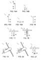
- FIG. 1is a side view of an embodiment of a soft tissue anchor coupled to an implant, according to the present invention.
- FIG. 2is a side view of another embodiment of a soft tissue anchor, in a first position.
- FIG. 3is a side view of the soft tissue anchor of FIG. 2 , but in a second position.
- FIG. 4is a side view of another embodiment of a soft tissue anchor, in a first position.
- FIG. 5is a side view of the soft tissue anchor of FIG. 4 , but in a second position.
- FIG. 6is also side view of a soft tissue anchor of FIG. 4 , but in an alternative second position.
- FIG. 7is a side view of another embodiment of a soft tissue anchor, in a first position.
- FIG. 8is a side view of another embodiment of a soft tissue anchor, in an expanded first position.
- FIG. 9is a side view of the soft tissue anchor of FIG. 8 , but in a collapsed second position.
- FIG. 10is a side view of another embodiment of a soft tissue anchor with a distal portion that tapers to a point, with the distances D 1 and D 2 indicated.
- FIG. 11 ais a side view of another embodiment of a soft tissue anchor, with a central body element that defines an aperture with a passageway through its center.
- FIG. 11 bis a top view of the soft tissue anchor of FIG. 1 a.
- FIG. 12 ais a top view of another embodiment of a soft tissue anchor, with a support member that forms a coil around the central body element, in a second position.
- FIG. 12 bis a side view of the soft tissue anchor of FIG. 12 a.
- FIG. 13is a top view of the soft tissue anchor of FIG. 12 a , but in a first position.
- FIG. 14 ais a side view of another embodiment of a soft tissue anchor in a second position, and this anchor comprises an element with a coiled distal end that lies substantially in the same plane as the longitudinal axis of the element's proximal end.
- FIG. 14 bis a top view of the soft tissue anchor of FIG. 14 a.
- FIG. 15 ais a side view of another embodiment of a soft tissue anchor in a second position, and this anchor comprises an element with a coiled distal end that does not lie in the same plane as the longitudinal axis of the element's proximal end.
- FIG. 15 bis a top view of the soft tissue anchor of FIG. 15 a.
- FIG. 16is a side view of the soft tissue anchor of FIG. 14 or FIG. 15 a , in a first position.
- FIG. 17is a side view of another embodiment of a soft tissue anchor, with a proximal portion that includes an aperture for receiving an implant.
- FIG. 18is a side view of another embodiment of a soft tissue anchor, with a proximal portion that includes an eyelet for receiving an implant.
- FIG. 19is a side view of another embodiment of a soft tissue anchor, with a proximal portion that defines a lumen for receiving an implant.
- FIG. 20is a side view of another embodiment of a soft tissue anchor, with a proximal portion that defines a groove for receiving an implant.
- FIG. 21is a side view of another embodiment of a soft tissue anchor, with a proximal portion that includes threads for receiving an implant.
- FIG. 22 ais a side perspective view of an embodiment of a soft tissue anchor delivery device.
- FIG. 22 bis a magnified view of the distal end of the delivery device of FIG. 22 a.
- FIG. 23 ais a view of an embodiment of a cartridge for use with the delivery device of FIG. 22 a and/or FIG. 25 .
- FIG. 23 bis a magnified view of the distal end of an embodiment of the cartridge of FIG. 23 a.
- FIG. 24is a view of a soft tissue anchor according to the invention releasably engaged by a groove in the distal end of the cartridge of FIG. 23 b.
- FIG. 25is a side perspective view of another embodiment of a soft tissue anchor delivery device.
- FIG. 26 ais a side perspective view of the delivery device of FIG. 25 , with the cartridge of FIG. 23 a inserted and in position A.
- FIG. 26 bis a magnified view of the distal end of the delivery device of FIG. 26 a.
- FIG. 27 ais a view corresponding to FIG. 26 a , with the cartridge in position B.
- FIG. 27 bis a magnified view of the distal end of the delivery device of FIG. 27 a.
- FIG. 28is a view corresponding to FIG. 26 a , with the cartridge in position C.
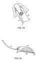
- FIG. 29is a view of another embodiment of a cartridge, with a distal portion that tapers to a point.
- FIG. 30is a view of the pointed distal end of the cartridge of FIG. 29 , with the soft tissue anchor of FIGS. 11 a and 11 b disposed thereon.
- FIG. 31 ais a side perspective view of the delivery device of FIG. 25 , with the cartridge of FIG. 29 inserted and in position A.
- FIG. 31 bis a magnified view of the distal end of the delivery device of FIG. 31 a.
- FIG. 32 ais a view corresponding to FIG. 31 a , with the cartridge in position B.
- FIG. 32 bis a magnified view of the distal end of the delivery device of FIG. 32 a.
- FIG. 33is a view corresponding to FIG. 31 a , with the cartridge in position C.
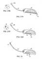
- FIG. 34is a cross section of a female patient's pelvic region.
- FIG. 35is a cross section corresponding to FIG. 34 , showing a delivery device according to the invention just prior to passage through the rectus abdominus.
- FIG. 36is a cross section corresponding to FIG. 34 , showing a delivery device according to the invention just after passage through the rectus abdominus.
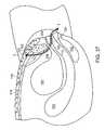
- FIG. 37is a cross section corresponding to FIG. 34 , showing a soft tissue anchor according to the invention in place between the rectus abdominus and the subcutaneous fat layer and an implant leading from the soft tissue anchor, through the endopelvic fascia, and out through the vagina.
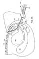
- FIG. 38is a sectional view of a female patient's pelvic region, showing an implant supported by two soft tissue anchors according to the invention.
- FIG. 39is a sectional view corresponding to FIG. 38 , showing a soft tissue anchor according to the invention in place between the rectus abdominus and the subcutaneous fat layer and two sutures leading from the soft tissue anchor, through the endopelvic fascia, and out through the vagina.
- FIG. 40is a sectional view corresponding to FIG. 39 , showing the two sutures after one has been moved to the opposite side of the urethra.
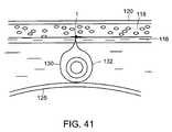
- FIG. 41is a sectional view corresponding to FIG. 39 , showing the two sutures joined beneath the urethra and forming a loop around the urethra.
- the inventionrelates to a soft tissue anchor for supporting an implant within the body of a patient.
- the soft tissue anchor 1includes a central body element 2 from which a plurality of support members 4 project.
- the central body element 2includes a distal portion 6 and a proximal portion 8 .
- the proximal portion 8includes a structure, such as an aperture or an eyelet, to which an implant 10 , such as a surgical mesh or sling, may be coupled.
- Ways of coupling the implant 10 to the proximal portion 8include tying, threading, crimping, affixing with an adhesive, or the like. Other ways of coupling the implant 10 to the proximal portion 8 are also possible.
- each support member 4is a cantilevered support projecting from the central body element 2 at point 12 .
- Each support member 4is capable of pivoting at point 12 between a first position, illustrated by FIG. 2 , wherein the support member 4 is articulated inward toward the proximal portion 8 of central body element 2 , and a second position, illustrated by FIG. 3 , wherein the support member 4 is articulated laterally away from the central body element 2 .
- Each support member 4can be biased in the second position such that it assumes that laterally extended second position when unrestrained.
- each support member 4can be formed of a shape-memory material that assumes the second position upon, for example, a temperature change (from, for example, ambient/room temperature where it is in the first position to body temperature where it is in the second position).
- each support member 4contains an elbow 14 that divides the support member 4 into an upper portion 16 and a lower portion 18 .
- Each support member 4is bent at the elbow 14 so that the lower portion 18 is deflected inward toward the central body element 2 in the proximal direction, defining an interior angle A 1 between the lower portion 18 and the upper portion 16 which is less than 180 degrees.
- Each support member 4is capable of pivoting at point 12 between a first position, illustrated by FIG. 4 , wherein each support member 4 is articulated inward toward the proximal portion 8 of central body element 2 , and a second position, illustrated by FIG. 5 , wherein each support member 4 is articulated laterally away from the central body element 2 .
- Each support member 4can be compliant and resilient and biased in the bent position at the elbow 14 , whereby the interior angle A 1 is less than 180 degrees.
- the lower portion 18 of each support member 4can be articulated such that the interior angle A 1 approaches or equals, but generally does not exceed, 180 degrees, as illustrated by FIG. 6 .
- each support member 4can return to its bent position at the elbow 14 .
- the soft tissue anchor 1can adopt a first position wherein each support member 4 is pivoted at the point 12 inward toward the distal portion 6 of central body element 2 .
- the lower portion 18 of each support member 4is bent in a proximal direction at the elbow 14 , thereby reducing the interior angle A 1 between the upper portion 16 and the lower portion 18 .
- each support member 4is bent at a compliant elbow 14 that divides the support member 4 into an upper portion 16 and a lower portion 18 .
- Each support member 4is bent at the elbow 14 so that the lower portion 18 is deflected inward toward the central body element 2 in the proximal direction, defining an interior angle A 1 between the upper portion 16 and the lower portion 18 which is less than 180 degrees.
- the soft tissue anchor 1can adopt an expanded first position wherein each support member 4 is pivoted inward at the point 12 toward the lateral portion 8 of central body element 2 .
- each support member 4may also be bent at the elbow 14 such that angle A 1 approaches or equals, but generally does not exceed, 180 degrees. Referring to FIG.
- the soft tissue anchor 1can adopt a collapsed second position wherein the upper portion 16 of each support member 4 is pivoted laterally away from the central body element 2 at the point 12 .
- the elbow 14is bent such that the angle A 1 is reduced, pivoting the lower portion 18 at the elbow 14 to a position closer to the upper portion 16 .
- Each support member 4can be biased in the collapsed second position, as illustrated by FIG. 9 .
- each support member 4can be formed of a shape-memory material that assumes the collapsed second position upon, for example, a temperature change (from, for example, ambient/room temperature where it is in the expanded first position to body temperature where it is in the collapsed second position).
- the distal portion 6 of the central body element 2is tapered to a point 20 .
- Each support member 4can be bent at the elbow 14 so that the lower portion 18 is deflected inward toward the central body element 2 in the proximal direction.
- the distance D 1 from the distal end of the central body element 2 to each elbow 14is greater than the distance D 2 from the distal end of the central body element 2 to the tip of point 20 .
- the soft tissue anchor 1according to this embodiment is positioned within the patient, the patient's anterior tissue will contact each elbow 14 rather than the point 20 , thus protecting the anterior tissue from abrasion by the point 20 .
- the central body element 2is hollow, defining an aperture 22 that runs through the length of central body element 2 .
- the central body element 2can be cylindrical, defining a round aperture 22 .
- the central body elementcan be polygonal, defining a polygonal aperture.
- the soft tissue anchor 1contains a single support member 4 forming a coil 24 around a central body element 2 .
- the soft tissue anchor 1when acted upon by a restraining force, the soft tissue anchor 1 can adopt a first position wherein the coil 24 is wrapped tightly around the central body element 2 , decreasing the diameter of the coil 24 to a smaller diameter d 2 .
- the soft tissue anchor 1when the restraining force is removed, the soft tissue anchor 1 can adopt a second position, wherein the coil 24 returns to its more loosely-coiled configuration with a larger diameter d 1 .
- the soft tissue anchor 1comprises a compliant and resilient element 26 with a coiled distal portion 28 and an uncoiled proximal portion 30 .
- the element 26can be solid or can comprise a tube with its distal end closed.
- the coiled distal portion 28can lie substantially in the same plane as the longitudinal axis of the uncoiled proximal portion 30 , as illustrated in FIGS. 14 a and 14 b .
- the coiled distal portion 28can lie in a different plane than the longitudinal axis of the uncoiled proximal portion 30 , as illustrated by FIGS. 15 a and 15 b . Referring to FIG.
- the coiled distal portion 28when acted upon by a restraining force, can be deformed into a configuration that is substantially linear with the longitudinal axis of the uncoiled proximal portion 30 .
- This restraining forcecan be applied manually by the operator in preparation for loading the soft tissue anchor 1 into a delivery device, such as a cannula.
- a delivery devicesuch as a cannula.
- the delivery deviceitself provides the restraining force and maintains the soft tissue anchor 1 in the first position.
- the restraining forceis removed and the distal portion 28 returns to its coiled configuration, illustrated alternatively by FIGS. 14 a and 15 a.
- the proximal portion 8can include any of a number of structures capable of coupling an implant to the soft tissue anchor 1 .
- the structurecan be an aperture 40 , as illustrated by FIG. 17 , or an eyelet 42 , as illustrated by FIG. 18 .
- the structurecan also be a lumen 44 , as illustrated by FIG. 19 , or a groove 46 , as illustrated by FIG. 20 .
- at least some of the proximal portion 8can contain threads 48 to which a threaded mating element can be coupled, and the mating element can have the implant coupled thereto in any of a variety of ways, such as tying, crimping, or affixing with an adhesive, for example.
- a soft tissue anchor 1 described hereincan be fabricated from one or more polymers, including polyolefin, polycarbonate, nylon, and/or other bio-compatible thermoplastic or thermoset materials.
- a soft tissue anchor 1can be fabricated from one or more metals, including stainless steel, titanium, tantilum, and/or other bio-compatible metals, or it can be fabricated from a metal alloy, such as nickel/titanium or Nitinol.
- the implant 10is a surgical mesh.
- the surgical meshcan be fabricated from one or more bio-compatible materials, including polypropylene, polyesters, polyolefins, polytetrafluoroethylene, polyethylene, polyurethanes, nylons, and co-polymers thereof.
- the surgical meshcan be fabricated from naturally occurring tissue, or a hybrid of synthetic materials and naturally occurring tissues.
- the surgical meshmay also be made of absorbable materials, such as polyglycolic acid and polylactic acid.
- the implant 10can be a tape or a sling.
- the tape or slingmay be fabricated from any of a variety of synthetic and/or naturally occurring bio-compatible materials. Such materials may be filamentous or non-filamentous, elastic or inelastic, and may be porous, microporous, perforated, or impermeable.
- the properties of the tape or slingmay be selected based on the type of soft tissue anchor to which it will be coupled and the application for which the tape or sling will be used.
- the implant 10can also be one or more sutures.
- the suture(s)can be fabricated from one or more bio-compatible materials, including polypropylene, polyesters, polyolefins, polytetrafluoroethylene, polyethylene, polyurethanes, nylons, and co-polymers thereof.
- the implant 10may be coupled to the soft tissue anchor 1 by a number of methods, including tying, threading, crimping, affixing with an adhesive, or the like.
- the choice of the method of coupling to the proximal portion 8is determined by the type of the implant 10 and the corresponding coupling structure of the soft tissue anchor 1 .
- the soft tissue anchor 1 and the implant 10can be fabricated as a single continuous unit.
- the soft tissue anchor 1is positioned within the patient's body by way of a delivery device, such as the delivery device 50 of FIG. 22 a .
- the delivery device 50includes a first cannula 52 , a second cannula 54 , a retractable trocar 56 , a cartridge 58 , and a handle 60 .
- the retractable trocar 56is operatively joined through the distal end of the handle 60 to a button 61 .
- the first cannula 52 and the second cannula 54are cojoined lengthwise to form a probe 62 , such that the lumen of the first cannula 52 and the lumen of the second cannula 54 are parallel.
- the distal end of the first cannula 52can extend beyond the distal end of the second cannula 54 in the probe 62 .
- the first cannula 52 and the second cannula 54are rigid and can be made of materials such as stainless steel, plated carbon steel, or coated carbon steel.
- the proximal end of probe 62is joined to the distal end of the handle 60 at an aperture 64 so that the first cannula 52 is on the same side of the handle 60 as the button 61 .
- the probe 62forms an arc from the distal end of the probe 62 to about 10-75% of the length of the probe 62 .
- the probe 62forms an arc with the concave surface of the arc on the same side of the probe 62 as the button 61 of the handle 60 .
- the arc of the probe 62is selected to optimize the ease of insertion of the delivery system though the patient's tissues to position the implant 10 at the appropriate site within the patient's body.
- the retractable trocar 56is slidably positioned in the lumen of the first cannula 52 .
- the point of the trocar 56can be articulated from a retracted position to an extended position.
- the button 61is operatively joined to the trocar 56 .
- the button 61is depressed, the point of the trocar 56 is extended from the distal end of the first cannula 52 .
- the button 61is released, the point of the trocar 56 is retracted into the first cannula 52 .
- the button 61is spring biased so that the operator must manually hold the button 61 down to extend the point of the trocar 56 from the distal end of the first cannula 52 .
- the cartridge 58is joined at its proximal end to a cartridge tab 66 .
- the distal end of the cartridge 58can include a structure (for example, a groove 65 ) for releasably engaging the soft tissue anchor 1 .
- the cartridge 58is made of a flexible material so it can follow the arc of the second cannula 54 .
- the cartridge 58can be completely removed from the handle 60 to load the soft tissue anchor 1 and the implant 10 into the second cannula 54 .
- the cartridge 58is then slidably positioned within the lumen of the second cannula 54 .
- the soft tissue anchor 1is moved toward the distal end of the second cannula 54 by moving the cartridge tab 66 forward toward the distal end of the handle 60 .
- the first step in inserting the soft tissue anchor 1 into a patient's bodyis to load the soft tissue anchor 1 into the second cannula 54 .
- the soft tissue anchor 1can be inserted into the proximal end of the second cannula 54 , followed by the cartridge 58 .
- the soft tissue anchor 1can first be engaged by a structure, such as a groove 65 , included in the distal end of cartridge 58 , as illustrated by FIG. 24 .
- the cartridge 58is then inserted into the second cannula 54 . While inside the second cannula 54 , each of the support members 4 of the soft tissue anchor 1 assumes the first position.
- the cartridge tab 66is pushed toward the distal end of the handle 60 so that the soft tissue anchor 1 does not extend beyond the distal end of the second cannula 54 .
- the distal end of probe 62is then inserted into a body cavity.
- the button 61is depressed to extend the trocar 56 from the distal end of the first cannula 52 when it is necessary to penetrate and pass through soft tissue.
- the button 61is released to retract the trocar 56 into the first cannula 52 when no penetration is necessary.
- the cartridge tab 66is moved as far distally as possible, which pushes the soft tissue anchor 1 out of the distal end of the second cannula 54 .
- each of the support members 4assumes the second position, which inhibits the soft tissue anchor 1 from passing back through the soft tissue when a pull-back force is applied to the soft tissue anchor 1 by the implant 10 .
- the probe 62is removed from the body cavity, leaving the soft tissue anchor 1 and the implant 10 in place within the patient's body.
- the delivery device 50is suitable for delivering a soft tissue anchor 1 that has a distal portion 6 that tapers to a point 20 , as illustrated, for example, by FIG. 10 .
- the delivery device 50includes a cannula 67 , a cartridge 58 , and a handle 60 .
- the cannula 67is rigid and can be made of a material such as stainless steel, plated carbon steel, or coated carbon steel.
- the proximal end of the cannula 67is joined to the distal end of handle 60 at aperture 64 .
- the cannula 67forms an arc from the distal end of the cannula 67 to about 10-75% of the length of the cannula 67 .
- the cannula 67forms an arc with the concave surface of the arc on the same side of the cannula 67 as the top of the handle 60 .
- the arc of the cannula 67is selected to optimize the ease of insertion of the delivery system though the patient's tissues to position the implant 10 at the appropriate site within the patient's body.
- the cartridge 58is joined at its proximal end to a cartridge tab 66 .
- the distal end of the cartridge 58can include a structure for releasably engaging the soft tissue anchor 1 , for instance, a groove 65 , as illustrated by FIG. 23 b .
- the soft tissue anchor 1can be inserted into the proximal end of the cannula 67 followed by the cartridge 58 .
- the soft tissue anchor 1can be first engaged by the distal end of the cartridge 58 , as illustrated by FIG. 24 , and then the cartridge 58 can be slid into the cannula 67 . While inside the lumen of the cannula 67 , each of the support members 4 of the soft tissue anchor 1 assumes the first position.
- the cartridge 58can move between three positions—positions A, B and C—by moving the cartridge tab 66 forward toward the distal end of the handle 50 and back toward the proximal end of the handle 50 .
- positions A, B and Cby moving the cartridge tab 66 forward toward the distal end of the handle 50 and back toward the proximal end of the handle 50 .
- FIGS. 26 a and 26 bin position A, no portion of the soft tissue anchor 1 extends beyond the distal end of the cannula 67 .
- FIGS. 27 a and 27 bin position B, only the point 20 of the soft tissue anchor 1 is extended beyond the distal end of the cannula 67 .
- FIG. 28in position C, the soft tissue anchor 1 is pushed out of the distal end of the cannula 67 .
- the soft tissue anchor 1is inserted into a patient's body by first loading the soft tissue anchor 1 into the cannula 67 .
- the cartridge tab 66is moved to position B, where the point 20 extends from the distal end of the cannula 67 , when it is necessary to penetrate and pass through soft tissue.
- the cartridge tab 66is moved to position A, where the point 20 is retracted within the distal end of the cannula 67 , when no penetration is necessary.
- the cartridge tab 66is moved to position C, which pushes the soft tissue anchor 1 out of the distal end of the cannula 67 .
- each of the support members 4assumes the second position, which inhibits the soft tissue anchor 1 from passing back through the soft tissue when a pull-back force is applied to the soft tissue anchor 1 by the implant 10 .
- the cannula 67is removed from the body cavity, leaving the soft tissue anchor 1 and the implant 10 in place within the patient's body.
- the delivery device 50 illustrated by FIG. 25is used to deliver a soft tissue anchor 1 that has a hollow central body element 2 , as illustrated, for example, by FIGS. 11 a and 11 b .
- the distal end of the cartridge 58tapers from an edge 68 to a point 70 , as illustrated by FIG. 29 .
- FIG. 30when the cartridge 58 is threaded through the aperture 22 in the soft tissue anchor 1 , the point 70 extends beyond the distal end 6 of the soft tissue anchor 1 , and the soft tissue anchor 1 can move no farther down the length of the cartridge 58 than the edge 68 .
- the cartridge 58is slid into the lumen of the cannula 67 of the delivery device 50 . While inside the lumen of the cannula 67 , each of the support members 4 of the soft tissue anchor 1 assumes the first position.
- the cartridge 58can move between three positions—positions A, B and C—by moving the cartridge tab 66 forward toward the distal end of the handle 50 and back toward the proximal end of the handle 50 . Referring to FIGS. 31 a and 31 b , in position A, the point 70 of the cartridge 58 is fully retracted within the distal end of the cannula 67 . Referring to FIGS.
- the soft tissue anchor 1is inserted into a patient's body by first threading the distal end of the cartridge 58 through the aperture in the soft tissue anchor 1 .
- Cartridge 58is inserted into the cannula 67 .
- the cartridge tab 66is moved to position B, where the point 70 extends from the distal end of the cannula 67 , when it is necessary to penetrate and pass through soft tissue.
- the cartridge tab 66is moved to position A, where the point 70 is retracted within the distal end of the cannula 67 , when no penetration is necessary.
- the cartridge tab 66When the distal end of the cannula 67 reaches the appropriate site within the body cavity, the cartridge tab 66 is moved to position C, which pushes the soft tissue anchor 1 out of the distal end of the cannula 67 .
- each of the support members 4assumes the second position, which inhibits the soft tissue anchor 1 from passing back through the soft tissue when a pull-back force is applied to the soft tissue anchor 1 by the implant 10 .
- the cannula 67is removed from the body cavity, leaving the soft tissue anchor 1 and the implant 10 in place within the patient's body.
- the present inventioncan find use in a number of female pelvic floor reconstruction procedures, including the correction of vaginal, uterine, and rectal prolapses, repair of cystoceles, lateral defect repair, and for the treatment of urinary incontinence.
- the present inventionalso can be useful in procedures dealing with male patients.
- the soft tissue anchor 1is used to support a surgical mesh used for the treatment of female stress urinary incontinence (SUI).
- SUIfemale stress urinary incontinence
- FIG. 34illustrates a simplified cross-sectional view of a female patient's pelvic region.
- the bladder 100is located behind the pubic bone 102 .
- the urethra 104extends from the bladder 100 toward the urinary meatus 105 .
- the upper portion of the urethra 104constitutes the urethrovesical junction 106 , or the bladder neck. Support of the middle portion 107 of the urethra 104 , between the urethrovesical junction 106 and the urinary meatus 105 , is believed to be important for the treatment of SUI.
- the uterus 108located behind the bladder 100 , leads to the vagina 110 .
- the rectum 112is located behind the vagina.
- the rectus abdominus muscle 116which is attached to the pubic bone 102 by Cooper's ligament 114 , is located above the bladder 100 and the uterus 104 .
- a subcutaneous fat layer 118is located between the rectus abdominus 116 and the skin 120 .
- the maintenance of normal female continencedepends upon the proper support and stabilization of the bladder 100 and the urethra 104 , especially during period of abdominal stress, such as when the patient coughs or laughs.
- SUIcan be caused by the weakening or stretching of the ligaments or other tissues that support the urethra 104 to the point where the urethra 104 cannot prevent the release of urine during periods of abdominal stress.
- the present inventioncan be used to treat SUI by providing the urethral support necessary to maintain urinary continence.
- a soft tissue anchor 1to which a surgical mesh 122 has been coupled, is loaded into a delivery device 50 , which includes a first cannula 52 and a second cannula 54 that are cojoined lengthwise to form a probe 62 .
- An incision 124is made in the vaginal wall 125 directly beneath the urethra 104 .
- the distal end of the probe 62is inserted into the incision 124 , and the probe is guided along one side of the urethra 104 .
- the retractable trocar 56is extended from the distal end of the first cannula 52 in order to pierce the endopelvic tissue 126 and move the probe upward toward the rectus abdominus 116 .
- the trocar 56is retracted into the first cannula 52 , and the probe 62 is advanced further, pushing the subcutaneous fat layer 118 upward and separating it from the rectus abdominus 116 , but not penetrating it.
- the soft tissue anchor 1is ejected from the distal end of the second cannula 54 by advancing the cartridge tab 66 toward the distal end of the handle 60 . Once the soft tissue anchor 1 is deployed, the probe 62 is pulled back out of the incision, leaving the soft tissue anchor 1 resting on the rectus abdominus 116 beneath the subcutaneous fat layer 118 .
- the surgical mesh 122As the probe 62 is removed, the surgical mesh 122 , which is coupled to the embedded soft tissue anchor 1 , is pulled out of the distal end of the second cannula 54 . Referring to FIG. 37 , the surgical mesh 122 trails from the soft tissue anchor 1 , through the endopelvic tissue 126 along one side of the urethra 104 , and into the vagina 110 through the incision 124 in the vaginal wall 125 . The end of the surgical mesh 122 which is trailing in the vagina typically is already coupled to a second soft tissue anchor 1 ′, which is then loaded into the delivery device 50 .
- the above procedureis repeated advancing the probe 62 along the other side of the urethra 104 and implanting the second soft tissue anchor 1 ′ between subcutaneous fat layer 118 and the rectus abdominus 116 .
- the surgical mesh 122held in position by the two tissue anchors 1 and 1 ′, provides the urethral support necessary for the treatment of SUI.
- a single soft tissue anchor 1can be used to anchor an implant to soft tissue for use in pelvic floor reconstruction procedures, such as the treatment of SUI.
- a soft tissue anchor 1 that is coupled to two sutures, 130 and 132can be implanted between subcutaneous fat layer 118 and the rectus abdominus 116 as described above.
- One of the suturescan then be passed back through the incision 124 in the vaginal wall 125 , over the urethra 104 , and through a second incision 136 in the vaginal wall 125 , as illustrated by FIG. 40 .
- the ends of the two sutures 130 and 132can then be joined together beneath the urethra 104 , forming a loop around the urethra 104 , as illustrated by FIG. 41 .
- the ends of the two suturescan also be joined to another implant, such as a surgical mesh or surgical sling, placed beneath the urethra.
- the implant used for pelvic floor reconstruction procedurescan be pre-coupled to one or more soft tissue anchors according to the invention, and this implant/anchor unit can be sold separately or together with a suitable delivery system. Surgeons and/or other medical professionals can then use the implant/anchor unit to perform surgical procedures, for example, pelvic floor reconstruction procedures.
Landscapes
- Health & Medical Sciences (AREA)
- Surgery (AREA)
- Life Sciences & Earth Sciences (AREA)
- Biomedical Technology (AREA)
- Nuclear Medicine, Radiotherapy & Molecular Imaging (AREA)
- Engineering & Computer Science (AREA)
- Heart & Thoracic Surgery (AREA)
- Medical Informatics (AREA)
- Molecular Biology (AREA)
- Animal Behavior & Ethology (AREA)
- General Health & Medical Sciences (AREA)
- Public Health (AREA)
- Veterinary Medicine (AREA)
- Rheumatology (AREA)
- Prostheses (AREA)
Abstract
Description
Claims (13)
Priority Applications (3)
| Application Number | Priority Date | Filing Date | Title |
|---|---|---|---|
| US10/325,125US8562646B2 (en) | 2002-12-19 | 2002-12-19 | Anchoring to soft tissue |
| PCT/US2003/040453WO2004056273A1 (en) | 2002-12-19 | 2003-12-17 | Anchoring to soft tissue |
| AU2003297986AAU2003297986A1 (en) | 2002-12-19 | 2003-12-17 | Anchoring to soft tissue |
Applications Claiming Priority (1)
| Application Number | Priority Date | Filing Date | Title |
|---|---|---|---|
| US10/325,125US8562646B2 (en) | 2002-12-19 | 2002-12-19 | Anchoring to soft tissue |
Publications (2)
| Publication Number | Publication Date |
|---|---|
| US20040122474A1 US20040122474A1 (en) | 2004-06-24 |
| US8562646B2true US8562646B2 (en) | 2013-10-22 |
Family
ID=32593668
Family Applications (1)
| Application Number | Title | Priority Date | Filing Date |
|---|---|---|---|
| US10/325,125Expired - Fee RelatedUS8562646B2 (en) | 2002-12-19 | 2002-12-19 | Anchoring to soft tissue |
Country Status (3)
| Country | Link |
|---|---|
| US (1) | US8562646B2 (en) |
| AU (1) | AU2003297986A1 (en) |
| WO (1) | WO2004056273A1 (en) |
Cited By (13)
| Publication number | Priority date | Publication date | Assignee | Title |
|---|---|---|---|---|
| US9265514B2 (en) | 2012-04-17 | 2016-02-23 | Miteas Ltd. | Manipulator for grasping tissue |
| US10105132B2 (en) | 2005-05-20 | 2018-10-23 | Neotract, Inc. | Devices, systems and methods for treating benign prostatic hyperplasia and other conditions |
| US10130353B2 (en) | 2012-06-29 | 2018-11-20 | Neotract, Inc. | Flexible system for delivering an anchor |
| US10143461B2 (en) | 2005-05-20 | 2018-12-04 | Neotract, Inc. | Devices, systems and methods for retracting, lifting, compressing, supporting or repositioning tissues or anatomical structures |
| US10195014B2 (en) | 2005-05-20 | 2019-02-05 | Neotract, Inc. | Devices, systems and methods for treating benign prostatic hyperplasia and other conditions |
| US10265061B2 (en) | 2005-05-20 | 2019-04-23 | Neotract, Inc. | Latching anchor device |
| US10292801B2 (en) | 2012-03-29 | 2019-05-21 | Neotract, Inc. | System for delivering anchors for treating incontinence |
| US10299780B2 (en) | 2005-05-20 | 2019-05-28 | Neotract, Inc. | Apparatus and method for manipulating or retracting tissue and anatomical structure |
| US10426509B2 (en) | 2005-05-20 | 2019-10-01 | Neotract, Inc. | Median lobe destruction apparatus and method |
| US10492792B2 (en) | 2005-05-20 | 2019-12-03 | Neotract, Inc. | Devices, systems and methods for treating benign prostatic hyperplasia and other conditions |
| US10925587B2 (en) | 2005-05-20 | 2021-02-23 | Neotract, Inc. | Anchor delivery system |
| US11672520B2 (en) | 2017-12-23 | 2023-06-13 | Teleflex Life Sciences Limited | Expandable tissue engagement apparatus and method |
| US12440301B2 (en) | 2019-10-30 | 2025-10-14 | Teleflex Life Sciences Llc | System for delivery of a fiducial marker |
Families Citing this family (71)
| Publication number | Priority date | Publication date | Assignee | Title |
|---|---|---|---|---|
| US20050192629A1 (en)* | 1999-06-25 | 2005-09-01 | Usgi Medical Inc. | Methods and apparatus for creating and regulating a gastric stoma |
| US20040122456A1 (en)* | 2002-12-11 | 2004-06-24 | Saadat Vahid C. | Methods and apparatus for gastric reduction |
| US7744613B2 (en) | 1999-06-25 | 2010-06-29 | Usgi Medical, Inc. | Apparatus and methods for forming and securing gastrointestinal tissue folds |
| US7637905B2 (en) | 2003-01-15 | 2009-12-29 | Usgi Medical, Inc. | Endoluminal tool deployment system |
| US7416554B2 (en) | 2002-12-11 | 2008-08-26 | Usgi Medical Inc | Apparatus and methods for forming and securing gastrointestinal tissue folds |
| US7160312B2 (en)* | 1999-06-25 | 2007-01-09 | Usgi Medical, Inc. | Implantable artificial partition and methods of use |
| US7618426B2 (en) | 2002-12-11 | 2009-11-17 | Usgi Medical, Inc. | Apparatus and methods for forming gastrointestinal tissue approximations |
| US7942884B2 (en) | 2002-12-11 | 2011-05-17 | Usgi Medical, Inc. | Methods for reduction of a gastric lumen |
| US7942898B2 (en)* | 2002-12-11 | 2011-05-17 | Usgi Medical, Inc. | Delivery systems and methods for gastric reduction |
| US8216252B2 (en) | 2004-05-07 | 2012-07-10 | Usgi Medical, Inc. | Tissue manipulation and securement system |
| TW200506345A (en)* | 2003-08-14 | 2005-02-16 | Au Optronics Corp | Water quality analysis method using potassium permanganate |
| US20050251189A1 (en) | 2004-05-07 | 2005-11-10 | Usgi Medical Inc. | Multi-position tissue manipulation assembly |
| US7347863B2 (en)* | 2004-05-07 | 2008-03-25 | Usgi Medical, Inc. | Apparatus and methods for manipulating and securing tissue |
| US7361180B2 (en) | 2004-05-07 | 2008-04-22 | Usgi Medical, Inc. | Apparatus for manipulating and securing tissue |
| US7736374B2 (en) | 2004-05-07 | 2010-06-15 | Usgi Medical, Inc. | Tissue manipulation and securement system |
| US20050251159A1 (en)* | 2004-05-07 | 2005-11-10 | Usgi Medical Inc. | Methods and apparatus for grasping and cinching tissue anchors |
| US7520884B2 (en) | 2004-05-07 | 2009-04-21 | Usgi Medical Inc. | Methods for performing gastroplasty |
| US8444657B2 (en) | 2004-05-07 | 2013-05-21 | Usgi Medical, Inc. | Apparatus and methods for rapid deployment of tissue anchors |
| US7918869B2 (en) | 2004-05-07 | 2011-04-05 | Usgi Medical, Inc. | Methods and apparatus for performing endoluminal gastroplasty |
| US7390329B2 (en) | 2004-05-07 | 2008-06-24 | Usgi Medical, Inc. | Methods for grasping and cinching tissue anchors |
| US8257394B2 (en) | 2004-05-07 | 2012-09-04 | Usgi Medical, Inc. | Apparatus and methods for positioning and securing anchors |
| US8057511B2 (en)* | 2004-05-07 | 2011-11-15 | Usgi Medical, Inc. | Apparatus and methods for positioning and securing anchors |
| US7678135B2 (en) | 2004-06-09 | 2010-03-16 | Usgi Medical, Inc. | Compressible tissue anchor assemblies |
| US7695493B2 (en) | 2004-06-09 | 2010-04-13 | Usgi Medical, Inc. | System for optimizing anchoring force |
| US8206417B2 (en) | 2004-06-09 | 2012-06-26 | Usgi Medical Inc. | Apparatus and methods for optimizing anchoring force |
| US7736379B2 (en) | 2004-06-09 | 2010-06-15 | Usgi Medical, Inc. | Compressible tissue anchor assemblies |
| AU2005269338B2 (en)* | 2004-07-28 | 2012-02-02 | Ethicon, Inc. | Minimally invasive medical implant and insertion device and method for using the same |
| US8500624B2 (en)* | 2004-10-25 | 2013-08-06 | Boston Scientific Scimed, Inc. | Systems and methods for sling delivery and placement |
| US8087413B2 (en)* | 2005-01-14 | 2012-01-03 | Usgi Medical Inc. | Attenuation of environmental parameters on a gastric lumen |
| US8096303B2 (en) | 2005-02-08 | 2012-01-17 | Koninklijke Philips Electronics N.V | Airway implants and methods and devices for insertion and retrieval |
| JP4981690B2 (en)* | 2005-02-08 | 2012-07-25 | コーニンクレッカ フィリップス エレクトロニクス エヌ ヴィ | System and method for percutaneous lingual plastic surgery |
| US8371307B2 (en) | 2005-02-08 | 2013-02-12 | Koninklijke Philips Electronics N.V. | Methods and devices for the treatment of airway obstruction, sleep apnea and snoring |
| US8425535B2 (en) | 2005-05-20 | 2013-04-23 | Neotract, Inc. | Multi-actuating trigger anchor delivery system |
| US8945152B2 (en) | 2005-05-20 | 2015-02-03 | Neotract, Inc. | Multi-actuating trigger anchor delivery system |
| US9504461B2 (en) | 2005-05-20 | 2016-11-29 | Neotract, Inc. | Anchor delivery system |
| US9585651B2 (en) | 2005-05-26 | 2017-03-07 | Usgi Medical, Inc. | Methods and apparatus for securing and deploying tissue anchors |
| US8298291B2 (en) | 2005-05-26 | 2012-10-30 | Usgi Medical, Inc. | Methods and apparatus for securing and deploying tissue anchors |
| WO2007008209A1 (en)* | 2005-07-13 | 2007-01-18 | Boston Scientific Scimed Inc. | Snap fit sling anchor system and related methods |
| JP2009515564A (en) | 2005-08-04 | 2009-04-16 | シー・アール・バード・インコーポレイテツド | Pelvic implant system and method |
| US7815562B2 (en)* | 2005-08-11 | 2010-10-19 | Boston Scientific Scimed, Inc. | Tubular implantable sling and related delivery systems, methods and devices |
| US8186355B2 (en) | 2005-11-09 | 2012-05-29 | Koninklijke Philips Electronics N.V. | Glossoplasty using tissue anchor glossopexy with volumetric tongue reduction |
| WO2007059199A2 (en) | 2005-11-14 | 2007-05-24 | C.R. Bard, Inc. | Sling anchor system |
| US7637860B2 (en)* | 2005-11-16 | 2009-12-29 | Boston Scientific Scimed, Inc. | Devices for minimally invasive pelvic surgery |
| US7513865B2 (en)* | 2005-12-20 | 2009-04-07 | Boston Scientific Scimed, Inc. | Flattened tubular mesh sling and related methods |
| US8726909B2 (en) | 2006-01-27 | 2014-05-20 | Usgi Medical, Inc. | Methods and apparatus for revision of obesity procedures |
| US8870916B2 (en) | 2006-07-07 | 2014-10-28 | USGI Medical, Inc | Low profile tissue anchors, tissue anchor systems, and methods for their delivery and use |
| WO2008033950A2 (en) | 2006-09-13 | 2008-03-20 | C. R. Bard, Inc. | Urethral support system |
| WO2008052251A1 (en)* | 2006-10-30 | 2008-05-08 | Kvinno Centre Pty Ltd | Anchoring device and its implementation |
| EP2081517A4 (en)* | 2006-11-06 | 2017-06-21 | Caldera Medical, Inc. | Implants and procedures for treatment of pelvic floor disorders |
| FR2914178B1 (en)* | 2007-03-27 | 2010-05-14 | Cie De Rech En Composants Impl | IMPLANTABLE REINFORCEMENT PROSTHESIS WITH MOUNTING MEANS |
| US8206280B2 (en) | 2007-11-13 | 2012-06-26 | C. R. Bard, Inc. | Adjustable tissue support member |
| EP2247252A4 (en)* | 2008-02-14 | 2015-01-28 | Robert C Brown | Method for treating stress urinary incontinence and symptomatic pelvic relaxation |
| US9017382B2 (en)* | 2008-05-19 | 2015-04-28 | Ams Research Corporation | Collapsible tissue anchor device and method |
| US8944990B2 (en) | 2008-10-27 | 2015-02-03 | Ams Research Corporation | Surgical needle and anchor system with retractable features |
| WO2010078591A1 (en) | 2009-01-05 | 2010-07-08 | Caldera Medical, Inc. | Implants and procedures for supporting anatomical structures for treating conditions such as incontinence |
| US8430826B2 (en) | 2009-03-04 | 2013-04-30 | Covidien Lp | Specimen retrieval apparatus |
| US20110087249A1 (en)* | 2009-10-09 | 2011-04-14 | Tyco Healthcare Group Lp | Internal Tissue Anchors |
| US20110087067A1 (en)* | 2009-10-09 | 2011-04-14 | Tyco Healthcare Group Lp | Internal retractor systems |
| US9060837B2 (en)* | 2009-11-23 | 2015-06-23 | Ams Research Corporation | Patterned sling implant and method |
| AU2010321585B2 (en) | 2009-11-23 | 2013-03-28 | Boston Scientific Scimed, Inc. | Patterned implant and method |
| US9161749B2 (en) | 2011-04-14 | 2015-10-20 | Neotract, Inc. | Method and apparatus for treating sexual dysfunction |
| US9414903B2 (en)* | 2011-07-22 | 2016-08-16 | Astora Women's Health, Llc | Pelvic implant system and method |
| EP2734148B1 (en) | 2011-07-22 | 2019-06-05 | Boston Scientific Scimed, Inc. | Pelvic implant system |
| CN104220010B (en) | 2012-03-30 | 2016-11-23 | 泰尔茂株式会社 | Lancet device and sting device |
| US11083451B2 (en) | 2013-03-11 | 2021-08-10 | Boston Scientific Scimed, Inc. | Tissue anchor with insertion device |
| US9918719B2 (en)* | 2014-06-08 | 2018-03-20 | Sano V Pte Ltd | Devices and methods for reshaping blood vessels |
| CN110623696A (en)* | 2014-06-15 | 2019-12-31 | 安奇拉医疗有限公司 | Apparatus and method for suturing tissue |
| WO2016089595A1 (en)* | 2014-12-03 | 2016-06-09 | Boston Scientific Scimed, Inc. | Double barbed suture with needle delivery system |
| WO2018087769A1 (en) | 2016-11-13 | 2018-05-17 | Anchora Medical Ltd. | Minimally-invasive tissue suturing device |
| KR102180896B1 (en)* | 2020-01-07 | 2020-11-19 | 주식회사 에이알씨코리아 | Suture anchor deployment device |
| CN114286646B (en) | 2020-08-03 | 2024-03-08 | 泰利福生命科学有限公司 | Handle and cassette system for medical intervention |
Citations (59)
| Publication number | Priority date | Publication date | Assignee | Title |
|---|---|---|---|---|
| US2143910A (en)* | 1934-03-30 | 1939-01-17 | Davis & Geck Inc | Ribbon gut and method of using the same |
| US4006747A (en) | 1975-04-23 | 1977-02-08 | Ethicon, Inc. | Surgical method |
| US4172458A (en) | 1977-11-07 | 1979-10-30 | Pereyra Armand J | Surgical ligature carrier |
| US4669473A (en) | 1985-09-06 | 1987-06-02 | Acufex Microsurgical, Inc. | Surgical fastener |
| US4705040A (en) | 1985-11-18 | 1987-11-10 | Medi-Tech, Incorporated | Percutaneous fixation of hollow organs |
| US4938760A (en) | 1989-03-29 | 1990-07-03 | American Medical Systems, Inc. | Female suspension procedure |
| US5013292A (en) | 1989-02-24 | 1991-05-07 | R. Laborie Medical Corporation | Surgical correction of female urinary stress incontinence and kit therefor |
| US5041129A (en) | 1990-07-02 | 1991-08-20 | Acufex Microsurgical, Inc. | Slotted suture anchor and method of anchoring a suture |
| US5085661A (en) | 1990-10-29 | 1992-02-04 | Gerald Moss | Surgical fastener implantation device |
| US5149329A (en) | 1990-12-12 | 1992-09-22 | Wayne State University | Surgical suture carrier and method for urinary bladder neck suspension |
| US5207679A (en) | 1991-09-26 | 1993-05-04 | Mitek Surgical Products, Inc. | Suture anchor and installation tool |
| US5256133A (en) | 1990-09-05 | 1993-10-26 | Spitz Robert M | Device for correcting stress urinary incontinence |
| US5312438A (en) | 1993-05-03 | 1994-05-17 | Lanny L. Johnson | Suture anchor and method of use |
| US5370661A (en) | 1990-11-06 | 1994-12-06 | Branch; Thomas P. | Method and apparatus for re-approximating tissue |
| US5462561A (en)* | 1993-08-05 | 1995-10-31 | Voda; Jan K. | Suture device |
| US5501695A (en)* | 1992-05-27 | 1996-03-26 | The Anspach Effort, Inc. | Fastener for attaching objects to bones |
| US5549617A (en) | 1993-08-20 | 1996-08-27 | United States Surgical Corporation | Apparatus and method for applying and adjusting an anchoring device |
| WO1996040356A1 (en) | 1995-06-07 | 1996-12-19 | Ep Technologies, Inc. | Atrial appendage stasis reduction procedures and devices |
| US5611515A (en) | 1991-12-03 | 1997-03-18 | Boston Scientic Corporation | Bladder neck suspension procedure |
| US5643288A (en) | 1995-06-14 | 1997-07-01 | Incont, Inc. | Apparatus and method for laparoscopic urethropexy |
| US5645589A (en) | 1994-08-22 | 1997-07-08 | Li Medical Technologies, Inc. | Anchor and method for securement into a bore |
| US5647836A (en) | 1995-09-28 | 1997-07-15 | Blake, Iii; Joseph W. | Method and means for treating female urinary incontinence |
| US5674247A (en) | 1994-12-14 | 1997-10-07 | Influence Inc. | Staple and tread assembly particularly for use in power-driven staplers for medical suturing |
| US5697931A (en) | 1995-06-14 | 1997-12-16 | Incont, Inc. | Apparatus and method for laparoscopic urethopexy |
| US5702215A (en) | 1995-06-05 | 1997-12-30 | Li Medical Technologies, Inc. | Retractable fixation device |
| US5702421A (en) | 1995-01-11 | 1997-12-30 | Schneidt; Bernhard | Closure device for closing a vascular opening, such as patent ductus arteriosus |
| US5816258A (en) | 1996-06-13 | 1998-10-06 | General Surgical Innovations, Inc. | Bladder neck suspension method |
| US5954057A (en) | 1997-02-12 | 1999-09-21 | Li Medical Technologies, Inc. | Soft tissue suspension clip, clip assembly, emplacement tool and method |
| US5997556A (en) | 1997-06-30 | 1999-12-07 | Eva Corporation | Surgical fastener |
| US6030393A (en) | 1998-09-15 | 2000-02-29 | Corlew; Earvin L. | Needle and procedure for relieving urinary incontinence |
| US6039686A (en) | 1997-03-18 | 2000-03-21 | Kovac; S. Robert | System and a method for the long term cure of recurrent urinary female incontinence |
| US6042534A (en) | 1997-02-13 | 2000-03-28 | Scimed Life Systems, Inc. | Stabilization sling for use in minimally invasive pelvic surgery |
| US6056760A (en) | 1997-01-30 | 2000-05-02 | Nissho Corporation | Device for intracardiac suture |
| US6059801A (en) | 1997-03-24 | 2000-05-09 | Samimi; Darius | Bladder saver retropubic ligature carrier device |
| US6113611A (en) | 1998-05-28 | 2000-09-05 | Advanced Vascular Technologies, Llc | Surgical fastener and delivery system |
| WO2001021247A1 (en) | 1999-09-20 | 2001-03-29 | Appriva Medical, Inc. | Method and apparatus for closing a body lumen |
| US6231561B1 (en)* | 1999-09-20 | 2001-05-15 | Appriva Medical, Inc. | Method and apparatus for closing a body lumen |
| US6245082B1 (en) | 1997-02-13 | 2001-06-12 | Scimed Life Systems, Inc. | System for attaching a urethral sling to a suture |
| US6273852B1 (en) | 1999-06-09 | 2001-08-14 | Ethicon, Inc. | Surgical instrument and method for treating female urinary incontinence |
| US6306079B1 (en) | 1999-12-07 | 2001-10-23 | Arnaldo F. Trabucco | Mesh pubovaginal sling |
| US20010039423A1 (en) | 2000-04-14 | 2001-11-08 | Skiba Jeffry B. | Tissue anchoring devices, biological vessel suspending devices and systems and methods utilizing same |
| US6319272B1 (en) | 1996-11-08 | 2001-11-20 | Boston Scientific Corporation | Transvaginal anchor implantation device and method of use |
| US6328758B1 (en)* | 1998-04-21 | 2001-12-11 | Tornier Sa | Suture anchor with reversible expansion |
| WO2001097676A2 (en) | 2000-06-22 | 2001-12-27 | Cardiac Assist Technologies, Inc. | Hard or soft tissue closure |
| WO2002017771A2 (en) | 2000-09-01 | 2002-03-07 | Advanced Vascular Technologies, Llc | Multi-fastener surgical apparatus and method |
| US6382214B1 (en) | 1998-04-24 | 2002-05-07 | American Medical Systems, Inc. | Methods and apparatus for correction of urinary and gynecological pathologies including treatment of male incontinence and female cystocele |
| US6387041B1 (en) | 1999-01-08 | 2002-05-14 | Boaz Harari | Tack device |
| US6406234B2 (en) | 1998-06-04 | 2002-06-18 | Synthes (Usa) | Blind rivet with fastener |
| US6406423B1 (en) | 2000-01-21 | 2002-06-18 | Sofradim Production | Method for surgical treatment of urinary incontinence and device for carrying out said method |
| US6423080B1 (en) | 1997-02-13 | 2002-07-23 | Scimed Life Systems, Inc. | Percutaneous and hiatal devices and methods for use in minimally invasive pelvic surgery |
| US6428562B2 (en) | 1996-11-15 | 2002-08-06 | Peter M. Bonutti | Apparatus and method for use in positioning an anchor |
| US6447524B1 (en) | 2000-10-19 | 2002-09-10 | Ethicon Endo-Surgery, Inc. | Fastener for hernia mesh fixation |
| US20020161382A1 (en) | 2001-03-29 | 2002-10-31 | Neisz Johann J. | Implant inserted without bone anchors |
| US6482210B1 (en) | 1998-11-12 | 2002-11-19 | Orthopaedic Biosystems, Ltd., Inc. | Soft tissue/ligament to bone fixation device with inserter |
| US20020183786A1 (en) | 2001-05-30 | 2002-12-05 | Timothy Girton | Implantable obstruction device for septal defects |
| US20030045893A1 (en) | 2001-09-06 | 2003-03-06 | Integrated Vascular Systems, Inc. | Clip apparatus for closing septal defects and methods of use |
| US20030050665A1 (en) | 2001-09-07 | 2003-03-13 | Integrated Vascular Systems, Inc. | Needle apparatus for closing septal defects and methods for using such apparatus |
| US6537198B1 (en) | 2000-03-21 | 2003-03-25 | Myocor, Inc. | Splint assembly for improving cardiac function in hearts, and method for implanting the splint assembly |
| US6960160B2 (en)* | 2000-10-12 | 2005-11-01 | Gyneideas, Limited | Apparatus and method for treating female urinary incontinence |
- 2002
- 2002-12-19USUS10/325,125patent/US8562646B2/ennot_activeExpired - Fee Related
- 2003
- 2003-12-17AUAU2003297986Apatent/AU2003297986A1/ennot_activeAbandoned
- 2003-12-17WOPCT/US2003/040453patent/WO2004056273A1/ennot_activeApplication Discontinuation
Patent Citations (62)
| Publication number | Priority date | Publication date | Assignee | Title |
|---|---|---|---|---|
| US2143910A (en)* | 1934-03-30 | 1939-01-17 | Davis & Geck Inc | Ribbon gut and method of using the same |
| US4006747A (en) | 1975-04-23 | 1977-02-08 | Ethicon, Inc. | Surgical method |
| US4172458A (en) | 1977-11-07 | 1979-10-30 | Pereyra Armand J | Surgical ligature carrier |
| US4669473A (en) | 1985-09-06 | 1987-06-02 | Acufex Microsurgical, Inc. | Surgical fastener |
| US4705040A (en) | 1985-11-18 | 1987-11-10 | Medi-Tech, Incorporated | Percutaneous fixation of hollow organs |
| US5013292A (en) | 1989-02-24 | 1991-05-07 | R. Laborie Medical Corporation | Surgical correction of female urinary stress incontinence and kit therefor |
| US4938760A (en) | 1989-03-29 | 1990-07-03 | American Medical Systems, Inc. | Female suspension procedure |
| US5041129A (en) | 1990-07-02 | 1991-08-20 | Acufex Microsurgical, Inc. | Slotted suture anchor and method of anchoring a suture |
| US5256133A (en) | 1990-09-05 | 1993-10-26 | Spitz Robert M | Device for correcting stress urinary incontinence |
| US5085661A (en) | 1990-10-29 | 1992-02-04 | Gerald Moss | Surgical fastener implantation device |
| US5370661A (en) | 1990-11-06 | 1994-12-06 | Branch; Thomas P. | Method and apparatus for re-approximating tissue |
| US5149329A (en) | 1990-12-12 | 1992-09-22 | Wayne State University | Surgical suture carrier and method for urinary bladder neck suspension |
| US5207679A (en) | 1991-09-26 | 1993-05-04 | Mitek Surgical Products, Inc. | Suture anchor and installation tool |
| US5611515A (en) | 1991-12-03 | 1997-03-18 | Boston Scientic Corporation | Bladder neck suspension procedure |
| US5501695A (en)* | 1992-05-27 | 1996-03-26 | The Anspach Effort, Inc. | Fastener for attaching objects to bones |
| US5312438A (en) | 1993-05-03 | 1994-05-17 | Lanny L. Johnson | Suture anchor and method of use |
| US5462561A (en)* | 1993-08-05 | 1995-10-31 | Voda; Jan K. | Suture device |
| US5549617A (en) | 1993-08-20 | 1996-08-27 | United States Surgical Corporation | Apparatus and method for applying and adjusting an anchoring device |
| US5562689A (en) | 1993-08-20 | 1996-10-08 | United States Surgical Corporation | Apparatus and method for applying and adjusting an anchoring device |
| US5645589A (en) | 1994-08-22 | 1997-07-08 | Li Medical Technologies, Inc. | Anchor and method for securement into a bore |
| US5674247A (en) | 1994-12-14 | 1997-10-07 | Influence Inc. | Staple and tread assembly particularly for use in power-driven staplers for medical suturing |
| US5702421A (en) | 1995-01-11 | 1997-12-30 | Schneidt; Bernhard | Closure device for closing a vascular opening, such as patent ductus arteriosus |
| US5702215A (en) | 1995-06-05 | 1997-12-30 | Li Medical Technologies, Inc. | Retractable fixation device |
| WO1996040356A1 (en) | 1995-06-07 | 1996-12-19 | Ep Technologies, Inc. | Atrial appendage stasis reduction procedures and devices |
| US5643288A (en) | 1995-06-14 | 1997-07-01 | Incont, Inc. | Apparatus and method for laparoscopic urethropexy |
| US5697931A (en) | 1995-06-14 | 1997-12-16 | Incont, Inc. | Apparatus and method for laparoscopic urethopexy |
| US5647836A (en) | 1995-09-28 | 1997-07-15 | Blake, Iii; Joseph W. | Method and means for treating female urinary incontinence |
| US5816258A (en) | 1996-06-13 | 1998-10-06 | General Surgical Innovations, Inc. | Bladder neck suspension method |
| US6319272B1 (en) | 1996-11-08 | 2001-11-20 | Boston Scientific Corporation | Transvaginal anchor implantation device and method of use |
| US6428562B2 (en) | 1996-11-15 | 2002-08-06 | Peter M. Bonutti | Apparatus and method for use in positioning an anchor |
| US6056760A (en) | 1997-01-30 | 2000-05-02 | Nissho Corporation | Device for intracardiac suture |
| US5954057A (en) | 1997-02-12 | 1999-09-21 | Li Medical Technologies, Inc. | Soft tissue suspension clip, clip assembly, emplacement tool and method |
| US6042534A (en) | 1997-02-13 | 2000-03-28 | Scimed Life Systems, Inc. | Stabilization sling for use in minimally invasive pelvic surgery |
| US6423080B1 (en) | 1997-02-13 | 2002-07-23 | Scimed Life Systems, Inc. | Percutaneous and hiatal devices and methods for use in minimally invasive pelvic surgery |
| US6245082B1 (en) | 1997-02-13 | 2001-06-12 | Scimed Life Systems, Inc. | System for attaching a urethral sling to a suture |
| US6039686A (en) | 1997-03-18 | 2000-03-21 | Kovac; S. Robert | System and a method for the long term cure of recurrent urinary female incontinence |
| US6328686B1 (en) | 1997-03-18 | 2001-12-11 | American Medical Systems, Inc. | Transvaginal system and method for treating female urinary incontinence |
| US6322492B1 (en) | 1997-03-18 | 2001-11-27 | American Medical Systems, Inc. | Transvaginal method for securing a bone anchor |
| US6059801A (en) | 1997-03-24 | 2000-05-09 | Samimi; Darius | Bladder saver retropubic ligature carrier device |
| US5997556A (en) | 1997-06-30 | 1999-12-07 | Eva Corporation | Surgical fastener |
| US6328758B1 (en)* | 1998-04-21 | 2001-12-11 | Tornier Sa | Suture anchor with reversible expansion |
| US6382214B1 (en) | 1998-04-24 | 2002-05-07 | American Medical Systems, Inc. | Methods and apparatus for correction of urinary and gynecological pathologies including treatment of male incontinence and female cystocele |
| US6113611A (en) | 1998-05-28 | 2000-09-05 | Advanced Vascular Technologies, Llc | Surgical fastener and delivery system |
| US6406234B2 (en) | 1998-06-04 | 2002-06-18 | Synthes (Usa) | Blind rivet with fastener |
| US6030393A (en) | 1998-09-15 | 2000-02-29 | Corlew; Earvin L. | Needle and procedure for relieving urinary incontinence |
| US6482210B1 (en) | 1998-11-12 | 2002-11-19 | Orthopaedic Biosystems, Ltd., Inc. | Soft tissue/ligament to bone fixation device with inserter |
| US6387041B1 (en) | 1999-01-08 | 2002-05-14 | Boaz Harari | Tack device |
| US6273852B1 (en) | 1999-06-09 | 2001-08-14 | Ethicon, Inc. | Surgical instrument and method for treating female urinary incontinence |
| WO2001021247A1 (en) | 1999-09-20 | 2001-03-29 | Appriva Medical, Inc. | Method and apparatus for closing a body lumen |
| US6231561B1 (en)* | 1999-09-20 | 2001-05-15 | Appriva Medical, Inc. | Method and apparatus for closing a body lumen |
| US6306079B1 (en) | 1999-12-07 | 2001-10-23 | Arnaldo F. Trabucco | Mesh pubovaginal sling |
| US6406423B1 (en) | 2000-01-21 | 2002-06-18 | Sofradim Production | Method for surgical treatment of urinary incontinence and device for carrying out said method |
| US6537198B1 (en) | 2000-03-21 | 2003-03-25 | Myocor, Inc. | Splint assembly for improving cardiac function in hearts, and method for implanting the splint assembly |
| US20010039423A1 (en) | 2000-04-14 | 2001-11-08 | Skiba Jeffry B. | Tissue anchoring devices, biological vessel suspending devices and systems and methods utilizing same |
| WO2001097676A2 (en) | 2000-06-22 | 2001-12-27 | Cardiac Assist Technologies, Inc. | Hard or soft tissue closure |
| WO2002017771A2 (en) | 2000-09-01 | 2002-03-07 | Advanced Vascular Technologies, Llc | Multi-fastener surgical apparatus and method |
| US6960160B2 (en)* | 2000-10-12 | 2005-11-01 | Gyneideas, Limited | Apparatus and method for treating female urinary incontinence |
| US6447524B1 (en) | 2000-10-19 | 2002-09-10 | Ethicon Endo-Surgery, Inc. | Fastener for hernia mesh fixation |
| US20020161382A1 (en) | 2001-03-29 | 2002-10-31 | Neisz Johann J. | Implant inserted without bone anchors |
| US20020183786A1 (en) | 2001-05-30 | 2002-12-05 | Timothy Girton | Implantable obstruction device for septal defects |
| US20030045893A1 (en) | 2001-09-06 | 2003-03-06 | Integrated Vascular Systems, Inc. | Clip apparatus for closing septal defects and methods of use |
| US20030050665A1 (en) | 2001-09-07 | 2003-03-13 | Integrated Vascular Systems, Inc. | Needle apparatus for closing septal defects and methods for using such apparatus |
Cited By (30)
| Publication number | Priority date | Publication date | Assignee | Title |
|---|---|---|---|---|
| US10925587B2 (en) | 2005-05-20 | 2021-02-23 | Neotract, Inc. | Anchor delivery system |
| US12201283B2 (en) | 2005-05-20 | 2025-01-21 | Teleflex Life Sciences Llc | Devices, systems and methods for treating benign prostatic hyperplasia and other conditions |
| US10105132B2 (en) | 2005-05-20 | 2018-10-23 | Neotract, Inc. | Devices, systems and methods for treating benign prostatic hyperplasia and other conditions |
| US11504149B2 (en) | 2005-05-20 | 2022-11-22 | Teleflex Life Sciences Limited | Median lobe destruction apparatus and method |
| US10143461B2 (en) | 2005-05-20 | 2018-12-04 | Neotract, Inc. | Devices, systems and methods for retracting, lifting, compressing, supporting or repositioning tissues or anatomical structures |
| US10195014B2 (en) | 2005-05-20 | 2019-02-05 | Neotract, Inc. | Devices, systems and methods for treating benign prostatic hyperplasia and other conditions |
| US10265061B2 (en) | 2005-05-20 | 2019-04-23 | Neotract, Inc. | Latching anchor device |
| US11471148B2 (en) | 2005-05-20 | 2022-10-18 | Teleflex Life Sciences Limited | Devices, systems and methods for treating benign prostatic hyperplasia and other conditions |
| US10299780B2 (en) | 2005-05-20 | 2019-05-28 | Neotract, Inc. | Apparatus and method for manipulating or retracting tissue and anatomical structure |
| US10426509B2 (en) | 2005-05-20 | 2019-10-01 | Neotract, Inc. | Median lobe destruction apparatus and method |
| US11090036B2 (en) | 2005-05-20 | 2021-08-17 | Neotract, Inc. | Devices, systems and methods for treating benign prostatic hyperplasia and other conditions |
| US10492792B2 (en) | 2005-05-20 | 2019-12-03 | Neotract, Inc. | Devices, systems and methods for treating benign prostatic hyperplasia and other conditions |
| US10575844B2 (en) | 2005-05-20 | 2020-03-03 | Neotract, Inc. | Devices, systems and methods for treating benign prostatic hyperplasia and other conditions |
| US10945719B2 (en) | 2005-05-20 | 2021-03-16 | Neotract, Inc. | Devices, systems and methods for retracting, lifting, compressing, supporting or repositioning tissues or anatomical structures |
| US10292801B2 (en) | 2012-03-29 | 2019-05-21 | Neotract, Inc. | System for delivering anchors for treating incontinence |
| US10441302B2 (en) | 2012-04-17 | 2019-10-15 | A-Base Korlatolt Felelossegu Tarsasag | Manipulator for grasping tissue |
| US9265514B2 (en) | 2012-04-17 | 2016-02-23 | Miteas Ltd. | Manipulator for grasping tissue |
| US11633203B2 (en) | 2012-04-17 | 2023-04-25 | A-Base Korlatolt Felelossegu Tarsasag | Manipulator for grasping tissue |
| US9610088B2 (en) | 2012-04-17 | 2017-04-04 | A-Base Korlatolt Felelossegu Tarsasag | Manipulator for grasping tissue |
| US12207831B2 (en) | 2012-04-17 | 2025-01-28 | A-Base Korlatolt Felelossegu Tarsasag | Manipulator for grasping tissue |
| US12324576B2 (en) | 2012-06-29 | 2025-06-10 | Teleflex Life Sciences Llc | Flexible system for delivering an anchor |
| US11331093B2 (en) | 2012-06-29 | 2022-05-17 | Teleflex Life Sciences Limited | Flexible system for delivering an anchor |
| US10130353B2 (en) | 2012-06-29 | 2018-11-20 | Neotract, Inc. | Flexible system for delivering an anchor |
| US12376842B2 (en) | 2012-06-29 | 2025-08-05 | Teleflex Life Sciences Llc | Flexible system for delivering an anchor |
| US10912637B2 (en) | 2013-03-14 | 2021-02-09 | Neotract, Inc. | Devices, systems and methods for treating benign prostatic hyperplasia and other conditions |
| US11850140B2 (en) | 2013-03-14 | 2023-12-26 | Teleflex Life Sciences Limited | Devices, systems and methods for treating benign prostatic hyperplasia and other conditions |
| US12042372B2 (en) | 2013-03-14 | 2024-07-23 | Teleflex Life Sciences Llc | Devices, systems and methods for treating benign prostatic hyperplasia and other conditions |
| US11672520B2 (en) | 2017-12-23 | 2023-06-13 | Teleflex Life Sciences Limited | Expandable tissue engagement apparatus and method |
| US12121228B2 (en) | 2017-12-23 | 2024-10-22 | Teleflex Life Sciences Llc | Expandable tissue engagement apparatus and method |
| US12440301B2 (en) | 2019-10-30 | 2025-10-14 | Teleflex Life Sciences Llc | System for delivery of a fiducial marker |
Also Published As
| Publication number | Publication date |
|---|---|
| AU2003297986A1 (en) | 2004-07-14 |
| US20040122474A1 (en) | 2004-06-24 |
| WO2004056273A1 (en) | 2004-07-08 |
Similar Documents
| Publication | Publication Date | Title |
|---|---|---|
| US8562646B2 (en) | Anchoring to soft tissue | |
| US9144483B2 (en) | Placing fixation devices | |
| US8597172B2 (en) | Tubular implantable sling and related delivery systems, methods and devices | |
| US10548702B2 (en) | Systems and methods for sling delivery and placement | |
| US8500624B2 (en) | Systems and methods for sling delivery and placement | |
| JP4767961B2 (en) | System and method for surgical implant placement | |
| US9226810B2 (en) | Systems and methods employing a push tube for delivering a urethral sling | |
| US8974367B2 (en) | Coaxial device for delivering an implant to a patient's pelvic region | |
| EP2191777B1 (en) | Sling assembly | |
| AU2014237186B2 (en) | Systems, tools, and methods for connecting to tissue | |
| US20140179987A1 (en) | Kit for Placing Fixation Devices | |
| US20160015501A1 (en) | Medical device | |
| WO2014162431A1 (en) | Medical tube and medical tube assembly |
Legal Events
| Date | Code | Title | Description |
|---|---|---|---|
| AS | Assignment | Owner name:SCIMED LIFE SYSTEMS, INC., MINNESOTA Free format text:ASSIGNMENT OF ASSIGNORS INTEREST;ASSIGNORS:GELLMAN, BARRY N.;MORIN, ARMOND A.;SLANDA, JOZEF;REEL/FRAME:013837/0925 Effective date:20021218 | |
| AS | Assignment | Owner name:BOSTON SCIENTIFIC SCIMED, INC., MINNESOTA Free format text:CHANGE OF NAME;ASSIGNOR:SCIMED LIFE SYSTEMS, INC.;REEL/FRAME:018505/0868 Effective date:20050101 Owner name:BOSTON SCIENTIFIC SCIMED, INC.,MINNESOTA Free format text:CHANGE OF NAME;ASSIGNOR:SCIMED LIFE SYSTEMS, INC.;REEL/FRAME:018505/0868 Effective date:20050101 | |
| FEPP | Fee payment procedure | Free format text:PAYOR NUMBER ASSIGNED (ORIGINAL EVENT CODE: ASPN); ENTITY STATUS OF PATENT OWNER: LARGE ENTITY | |
| REMI | Maintenance fee reminder mailed | ||
| LAPS | Lapse for failure to pay maintenance fees | Free format text:PATENT EXPIRED FOR FAILURE TO PAY MAINTENANCE FEES (ORIGINAL EVENT CODE: EXP.) | |
| STCH | Information on status: patent discontinuation | Free format text:PATENT EXPIRED DUE TO NONPAYMENT OF MAINTENANCE FEES UNDER 37 CFR 1.362 | |
| FP | Lapsed due to failure to pay maintenance fee | Effective date:20171022 |