US8562618B2 - Joint arthroplasty devices and surgical tools - Google Patents
Joint arthroplasty devices and surgical toolsDownload PDFInfo
- Publication number
- US8562618B2 US8562618B2US13/625,742US201213625742AUS8562618B2US 8562618 B2US8562618 B2US 8562618B2US 201213625742 AUS201213625742 AUS 201213625742AUS 8562618 B2US8562618 B2US 8562618B2
- Authority
- US
- United States
- Prior art keywords
- patient
- cartilage
- tibia
- tool
- joint
- Prior art date
- Legal status (The legal status is an assumption and is not a legal conclusion. Google has not performed a legal analysis and makes no representation as to the accuracy of the status listed.)
- Expired - Lifetime
Links
Images


Classifications
- A—HUMAN NECESSITIES
- A61—MEDICAL OR VETERINARY SCIENCE; HYGIENE
- A61F—FILTERS IMPLANTABLE INTO BLOOD VESSELS; PROSTHESES; DEVICES PROVIDING PATENCY TO, OR PREVENTING COLLAPSING OF, TUBULAR STRUCTURES OF THE BODY, e.g. STENTS; ORTHOPAEDIC, NURSING OR CONTRACEPTIVE DEVICES; FOMENTATION; TREATMENT OR PROTECTION OF EYES OR EARS; BANDAGES, DRESSINGS OR ABSORBENT PADS; FIRST-AID KITS
- A61F2/00—Filters implantable into blood vessels; Prostheses, i.e. artificial substitutes or replacements for parts of the body; Appliances for connecting them with the body; Devices providing patency to, or preventing collapsing of, tubular structures of the body, e.g. stents
- A61F2/02—Prostheses implantable into the body
- A61F2/30—Joints
- A61F2/3094—Designing or manufacturing processes
- A61F2/30942—Designing or manufacturing processes for designing or making customized prostheses, e.g. using templates, CT or NMR scans, finite-element analysis or CAD-CAM techniques
- A—HUMAN NECESSITIES
- A61—MEDICAL OR VETERINARY SCIENCE; HYGIENE
- A61F—FILTERS IMPLANTABLE INTO BLOOD VESSELS; PROSTHESES; DEVICES PROVIDING PATENCY TO, OR PREVENTING COLLAPSING OF, TUBULAR STRUCTURES OF THE BODY, e.g. STENTS; ORTHOPAEDIC, NURSING OR CONTRACEPTIVE DEVICES; FOMENTATION; TREATMENT OR PROTECTION OF EYES OR EARS; BANDAGES, DRESSINGS OR ABSORBENT PADS; FIRST-AID KITS
- A61F2/00—Filters implantable into blood vessels; Prostheses, i.e. artificial substitutes or replacements for parts of the body; Appliances for connecting them with the body; Devices providing patency to, or preventing collapsing of, tubular structures of the body, e.g. stents
- A61F2/02—Prostheses implantable into the body
- A61F2/30—Joints
- A61F2/46—Special tools for implanting artificial joints
- A—HUMAN NECESSITIES
- A61—MEDICAL OR VETERINARY SCIENCE; HYGIENE
- A61B—DIAGNOSIS; SURGERY; IDENTIFICATION
- A61B17/00—Surgical instruments, devices or methods
- A61B17/14—Surgical saws
- A61B17/15—Guides therefor
- A—HUMAN NECESSITIES
- A61—MEDICAL OR VETERINARY SCIENCE; HYGIENE
- A61B—DIAGNOSIS; SURGERY; IDENTIFICATION
- A61B17/00—Surgical instruments, devices or methods
- A61B17/14—Surgical saws
- A61B17/15—Guides therefor
- A61B17/154—Guides therefor for preparing bone for knee prosthesis
- A—HUMAN NECESSITIES
- A61—MEDICAL OR VETERINARY SCIENCE; HYGIENE
- A61B—DIAGNOSIS; SURGERY; IDENTIFICATION
- A61B17/00—Surgical instruments, devices or methods
- A61B17/14—Surgical saws
- A61B17/15—Guides therefor
- A61B17/154—Guides therefor for preparing bone for knee prosthesis
- A61B17/155—Cutting femur
- A—HUMAN NECESSITIES
- A61—MEDICAL OR VETERINARY SCIENCE; HYGIENE
- A61B—DIAGNOSIS; SURGERY; IDENTIFICATION
- A61B17/00—Surgical instruments, devices or methods
- A61B17/14—Surgical saws
- A61B17/15—Guides therefor
- A61B17/154—Guides therefor for preparing bone for knee prosthesis
- A61B17/157—Cutting tibia
- A—HUMAN NECESSITIES
- A61—MEDICAL OR VETERINARY SCIENCE; HYGIENE
- A61B—DIAGNOSIS; SURGERY; IDENTIFICATION
- A61B17/00—Surgical instruments, devices or methods
- A61B17/14—Surgical saws
- A61B17/15—Guides therefor
- A61B17/154—Guides therefor for preparing bone for knee prosthesis
- A61B17/158—Cutting patella
- A—HUMAN NECESSITIES
- A61—MEDICAL OR VETERINARY SCIENCE; HYGIENE
- A61B—DIAGNOSIS; SURGERY; IDENTIFICATION
- A61B17/00—Surgical instruments, devices or methods
- A61B17/16—Instruments for performing osteoclasis; Drills or chisels for bones; Trepans
- A—HUMAN NECESSITIES
- A61—MEDICAL OR VETERINARY SCIENCE; HYGIENE
- A61B—DIAGNOSIS; SURGERY; IDENTIFICATION
- A61B17/00—Surgical instruments, devices or methods
- A61B17/16—Instruments for performing osteoclasis; Drills or chisels for bones; Trepans
- A61B17/1662—Instruments for performing osteoclasis; Drills or chisels for bones; Trepans for particular parts of the body
- A61B17/1664—Instruments for performing osteoclasis; Drills or chisels for bones; Trepans for particular parts of the body for the hip
- A61B17/1666—Instruments for performing osteoclasis; Drills or chisels for bones; Trepans for particular parts of the body for the hip for the acetabulum
- A—HUMAN NECESSITIES
- A61—MEDICAL OR VETERINARY SCIENCE; HYGIENE
- A61B—DIAGNOSIS; SURGERY; IDENTIFICATION
- A61B17/00—Surgical instruments, devices or methods
- A61B17/16—Instruments for performing osteoclasis; Drills or chisels for bones; Trepans
- A61B17/1662—Instruments for performing osteoclasis; Drills or chisels for bones; Trepans for particular parts of the body
- A61B17/1664—Instruments for performing osteoclasis; Drills or chisels for bones; Trepans for particular parts of the body for the hip
- A61B17/1668—Instruments for performing osteoclasis; Drills or chisels for bones; Trepans for particular parts of the body for the hip for the upper femur
- A—HUMAN NECESSITIES
- A61—MEDICAL OR VETERINARY SCIENCE; HYGIENE
- A61B—DIAGNOSIS; SURGERY; IDENTIFICATION
- A61B17/00—Surgical instruments, devices or methods
- A61B17/16—Instruments for performing osteoclasis; Drills or chisels for bones; Trepans
- A61B17/1662—Instruments for performing osteoclasis; Drills or chisels for bones; Trepans for particular parts of the body
- A61B17/1671—Instruments for performing osteoclasis; Drills or chisels for bones; Trepans for particular parts of the body for the spine
- A—HUMAN NECESSITIES
- A61—MEDICAL OR VETERINARY SCIENCE; HYGIENE
- A61B—DIAGNOSIS; SURGERY; IDENTIFICATION
- A61B17/00—Surgical instruments, devices or methods
- A61B17/16—Instruments for performing osteoclasis; Drills or chisels for bones; Trepans
- A61B17/1662—Instruments for performing osteoclasis; Drills or chisels for bones; Trepans for particular parts of the body
- A61B17/1675—Instruments for performing osteoclasis; Drills or chisels for bones; Trepans for particular parts of the body for the knee
- A—HUMAN NECESSITIES
- A61—MEDICAL OR VETERINARY SCIENCE; HYGIENE
- A61B—DIAGNOSIS; SURGERY; IDENTIFICATION
- A61B17/00—Surgical instruments, devices or methods
- A61B17/16—Instruments for performing osteoclasis; Drills or chisels for bones; Trepans
- A61B17/17—Guides or aligning means for drills, mills, pins or wires
- A61B17/1739—Guides or aligning means for drills, mills, pins or wires specially adapted for particular parts of the body
- A61B17/1764—Guides or aligning means for drills, mills, pins or wires specially adapted for particular parts of the body for the knee
- A—HUMAN NECESSITIES
- A61—MEDICAL OR VETERINARY SCIENCE; HYGIENE
- A61B—DIAGNOSIS; SURGERY; IDENTIFICATION
- A61B17/00—Surgical instruments, devices or methods
- A61B17/56—Surgical instruments or methods for treatment of bones or joints; Devices specially adapted therefor
- A61B17/58—Surgical instruments or methods for treatment of bones or joints; Devices specially adapted therefor for osteosynthesis, e.g. bone plates, screws or setting implements
- A61B17/88—Osteosynthesis instruments; Methods or means for implanting or extracting internal or external fixation devices
- A—HUMAN NECESSITIES
- A61—MEDICAL OR VETERINARY SCIENCE; HYGIENE
- A61B—DIAGNOSIS; SURGERY; IDENTIFICATION
- A61B34/00—Computer-aided surgery; Manipulators or robots specially adapted for use in surgery
- A61B34/10—Computer-aided planning, simulation or modelling of surgical operations
- A—HUMAN NECESSITIES
- A61—MEDICAL OR VETERINARY SCIENCE; HYGIENE
- A61B—DIAGNOSIS; SURGERY; IDENTIFICATION
- A61B34/00—Computer-aided surgery; Manipulators or robots specially adapted for use in surgery
- A61B34/20—Surgical navigation systems; Devices for tracking or guiding surgical instruments, e.g. for frameless stereotaxis
- A—HUMAN NECESSITIES
- A61—MEDICAL OR VETERINARY SCIENCE; HYGIENE
- A61B—DIAGNOSIS; SURGERY; IDENTIFICATION
- A61B5/00—Measuring for diagnostic purposes; Identification of persons
- A61B5/45—For evaluating or diagnosing the musculoskeletal system or teeth
- A61B5/4528—Joints
- A—HUMAN NECESSITIES
- A61—MEDICAL OR VETERINARY SCIENCE; HYGIENE
- A61F—FILTERS IMPLANTABLE INTO BLOOD VESSELS; PROSTHESES; DEVICES PROVIDING PATENCY TO, OR PREVENTING COLLAPSING OF, TUBULAR STRUCTURES OF THE BODY, e.g. STENTS; ORTHOPAEDIC, NURSING OR CONTRACEPTIVE DEVICES; FOMENTATION; TREATMENT OR PROTECTION OF EYES OR EARS; BANDAGES, DRESSINGS OR ABSORBENT PADS; FIRST-AID KITS
- A61F2/00—Filters implantable into blood vessels; Prostheses, i.e. artificial substitutes or replacements for parts of the body; Appliances for connecting them with the body; Devices providing patency to, or preventing collapsing of, tubular structures of the body, e.g. stents
- A61F2/02—Prostheses implantable into the body
- A61F2/30—Joints
- A61F2/30756—Cartilage endoprostheses
- A—HUMAN NECESSITIES
- A61—MEDICAL OR VETERINARY SCIENCE; HYGIENE
- A61F—FILTERS IMPLANTABLE INTO BLOOD VESSELS; PROSTHESES; DEVICES PROVIDING PATENCY TO, OR PREVENTING COLLAPSING OF, TUBULAR STRUCTURES OF THE BODY, e.g. STENTS; ORTHOPAEDIC, NURSING OR CONTRACEPTIVE DEVICES; FOMENTATION; TREATMENT OR PROTECTION OF EYES OR EARS; BANDAGES, DRESSINGS OR ABSORBENT PADS; FIRST-AID KITS
- A61F2/00—Filters implantable into blood vessels; Prostheses, i.e. artificial substitutes or replacements for parts of the body; Appliances for connecting them with the body; Devices providing patency to, or preventing collapsing of, tubular structures of the body, e.g. stents
- A61F2/02—Prostheses implantable into the body
- A61F2/30—Joints
- A61F2/30767—Special external or bone-contacting surface, e.g. coating for improving bone ingrowth
- A61F2/30771—Special external or bone-contacting surface, e.g. coating for improving bone ingrowth applied in original prostheses, e.g. holes or grooves
- A—HUMAN NECESSITIES
- A61—MEDICAL OR VETERINARY SCIENCE; HYGIENE
- A61F—FILTERS IMPLANTABLE INTO BLOOD VESSELS; PROSTHESES; DEVICES PROVIDING PATENCY TO, OR PREVENTING COLLAPSING OF, TUBULAR STRUCTURES OF THE BODY, e.g. STENTS; ORTHOPAEDIC, NURSING OR CONTRACEPTIVE DEVICES; FOMENTATION; TREATMENT OR PROTECTION OF EYES OR EARS; BANDAGES, DRESSINGS OR ABSORBENT PADS; FIRST-AID KITS
- A61F2/00—Filters implantable into blood vessels; Prostheses, i.e. artificial substitutes or replacements for parts of the body; Appliances for connecting them with the body; Devices providing patency to, or preventing collapsing of, tubular structures of the body, e.g. stents
- A61F2/02—Prostheses implantable into the body
- A61F2/30—Joints
- A61F2/32—Joints for the hip
- A61F2/36—Femoral heads ; Femoral endoprostheses
- A—HUMAN NECESSITIES
- A61—MEDICAL OR VETERINARY SCIENCE; HYGIENE
- A61F—FILTERS IMPLANTABLE INTO BLOOD VESSELS; PROSTHESES; DEVICES PROVIDING PATENCY TO, OR PREVENTING COLLAPSING OF, TUBULAR STRUCTURES OF THE BODY, e.g. STENTS; ORTHOPAEDIC, NURSING OR CONTRACEPTIVE DEVICES; FOMENTATION; TREATMENT OR PROTECTION OF EYES OR EARS; BANDAGES, DRESSINGS OR ABSORBENT PADS; FIRST-AID KITS
- A61F2/00—Filters implantable into blood vessels; Prostheses, i.e. artificial substitutes or replacements for parts of the body; Appliances for connecting them with the body; Devices providing patency to, or preventing collapsing of, tubular structures of the body, e.g. stents
- A61F2/02—Prostheses implantable into the body
- A61F2/30—Joints
- A61F2/38—Joints for elbows or knees
- A61F2/3859—Femoral components
- A—HUMAN NECESSITIES
- A61—MEDICAL OR VETERINARY SCIENCE; HYGIENE
- A61F—FILTERS IMPLANTABLE INTO BLOOD VESSELS; PROSTHESES; DEVICES PROVIDING PATENCY TO, OR PREVENTING COLLAPSING OF, TUBULAR STRUCTURES OF THE BODY, e.g. STENTS; ORTHOPAEDIC, NURSING OR CONTRACEPTIVE DEVICES; FOMENTATION; TREATMENT OR PROTECTION OF EYES OR EARS; BANDAGES, DRESSINGS OR ABSORBENT PADS; FIRST-AID KITS
- A61F2/00—Filters implantable into blood vessels; Prostheses, i.e. artificial substitutes or replacements for parts of the body; Appliances for connecting them with the body; Devices providing patency to, or preventing collapsing of, tubular structures of the body, e.g. stents
- A61F2/02—Prostheses implantable into the body
- A61F2/30—Joints
- A61F2/46—Special tools for implanting artificial joints
- A61F2/4657—Measuring instruments used for implanting artificial joints
- B—PERFORMING OPERATIONS; TRANSPORTING
- B23—MACHINE TOOLS; METAL-WORKING NOT OTHERWISE PROVIDED FOR
- B23Q—DETAILS, COMPONENTS, OR ACCESSORIES FOR MACHINE TOOLS, e.g. ARRANGEMENTS FOR COPYING OR CONTROLLING; MACHINE TOOLS IN GENERAL CHARACTERISED BY THE CONSTRUCTION OF PARTICULAR DETAILS OR COMPONENTS; COMBINATIONS OR ASSOCIATIONS OF METAL-WORKING MACHINES, NOT DIRECTED TO A PARTICULAR RESULT
- B23Q17/00—Arrangements for observing, indicating or measuring on machine tools
- A—HUMAN NECESSITIES
- A61—MEDICAL OR VETERINARY SCIENCE; HYGIENE
- A61B—DIAGNOSIS; SURGERY; IDENTIFICATION
- A61B17/00—Surgical instruments, devices or methods
- A61B17/56—Surgical instruments or methods for treatment of bones or joints; Devices specially adapted therefor
- A61B17/58—Surgical instruments or methods for treatment of bones or joints; Devices specially adapted therefor for osteosynthesis, e.g. bone plates, screws or setting implements
- A61B17/68—Internal fixation devices, including fasteners and spinal fixators, even if a part thereof projects from the skin
- A61B17/70—Spinal positioners or stabilisers, e.g. stabilisers comprising fluid filler in an implant
- A61B17/7097—Stabilisers comprising fluid filler in an implant, e.g. balloon; devices for inserting or filling such implants
- A61B17/7098—Stabilisers comprising fluid filler in an implant, e.g. balloon; devices for inserting or filling such implants wherein the implant is permeable or has openings, e.g. fenestrated screw
- A—HUMAN NECESSITIES
- A61—MEDICAL OR VETERINARY SCIENCE; HYGIENE
- A61B—DIAGNOSIS; SURGERY; IDENTIFICATION
- A61B17/00—Surgical instruments, devices or methods
- A61B17/56—Surgical instruments or methods for treatment of bones or joints; Devices specially adapted therefor
- A61B17/58—Surgical instruments or methods for treatment of bones or joints; Devices specially adapted therefor for osteosynthesis, e.g. bone plates, screws or setting implements
- A61B17/88—Osteosynthesis instruments; Methods or means for implanting or extracting internal or external fixation devices
- A61B17/8802—Equipment for handling bone cement or other fluid fillers
- A61B17/8805—Equipment for handling bone cement or other fluid fillers for introducing fluid filler into bone or extracting it
- A—HUMAN NECESSITIES
- A61—MEDICAL OR VETERINARY SCIENCE; HYGIENE
- A61B—DIAGNOSIS; SURGERY; IDENTIFICATION
- A61B34/00—Computer-aided surgery; Manipulators or robots specially adapted for use in surgery
- A61B34/10—Computer-aided planning, simulation or modelling of surgical operations
- A61B2034/101—Computer-aided simulation of surgical operations
- A61B2034/102—Modelling of surgical devices, implants or prosthesis
- A—HUMAN NECESSITIES
- A61—MEDICAL OR VETERINARY SCIENCE; HYGIENE
- A61B—DIAGNOSIS; SURGERY; IDENTIFICATION
- A61B34/00—Computer-aided surgery; Manipulators or robots specially adapted for use in surgery
- A61B34/10—Computer-aided planning, simulation or modelling of surgical operations
- A61B2034/101—Computer-aided simulation of surgical operations
- A61B2034/105—Modelling of the patient, e.g. for ligaments or bones
- A—HUMAN NECESSITIES
- A61—MEDICAL OR VETERINARY SCIENCE; HYGIENE
- A61B—DIAGNOSIS; SURGERY; IDENTIFICATION
- A61B34/00—Computer-aided surgery; Manipulators or robots specially adapted for use in surgery
- A61B34/10—Computer-aided planning, simulation or modelling of surgical operations
- A61B2034/108—Computer aided selection or customisation of medical implants or cutting guides
- A—HUMAN NECESSITIES
- A61—MEDICAL OR VETERINARY SCIENCE; HYGIENE
- A61B—DIAGNOSIS; SURGERY; IDENTIFICATION
- A61B34/00—Computer-aided surgery; Manipulators or robots specially adapted for use in surgery
- A61B34/25—User interfaces for surgical systems
- A61B2034/256—User interfaces for surgical systems having a database of accessory information, e.g. including context sensitive help or scientific articles
- A—HUMAN NECESSITIES
- A61—MEDICAL OR VETERINARY SCIENCE; HYGIENE
- A61B—DIAGNOSIS; SURGERY; IDENTIFICATION
- A61B90/00—Instruments, implements or accessories specially adapted for surgery or diagnosis and not covered by any of the groups A61B1/00 - A61B50/00, e.g. for luxation treatment or for protecting wound edges
- A61B90/06—Measuring instruments not otherwise provided for
- A61B2090/061—Measuring instruments not otherwise provided for for measuring dimensions, e.g. length
- A—HUMAN NECESSITIES
- A61—MEDICAL OR VETERINARY SCIENCE; HYGIENE
- A61B—DIAGNOSIS; SURGERY; IDENTIFICATION
- A61B5/00—Measuring for diagnostic purposes; Identification of persons
- A61B5/45—For evaluating or diagnosing the musculoskeletal system or teeth
- A61B5/4504—Bones
- A—HUMAN NECESSITIES
- A61—MEDICAL OR VETERINARY SCIENCE; HYGIENE
- A61B—DIAGNOSIS; SURGERY; IDENTIFICATION
- A61B5/00—Measuring for diagnostic purposes; Identification of persons
- A61B5/45—For evaluating or diagnosing the musculoskeletal system or teeth
- A61B5/4514—Cartilage
- A—HUMAN NECESSITIES
- A61—MEDICAL OR VETERINARY SCIENCE; HYGIENE
- A61B—DIAGNOSIS; SURGERY; IDENTIFICATION
- A61B6/00—Apparatus or devices for radiation diagnosis; Apparatus or devices for radiation diagnosis combined with radiation therapy equipment
- A61B6/50—Apparatus or devices for radiation diagnosis; Apparatus or devices for radiation diagnosis combined with radiation therapy equipment specially adapted for specific body parts; specially adapted for specific clinical applications
- A61B6/508—Apparatus or devices for radiation diagnosis; Apparatus or devices for radiation diagnosis combined with radiation therapy equipment specially adapted for specific body parts; specially adapted for specific clinical applications for non-human patients
- A—HUMAN NECESSITIES
- A61—MEDICAL OR VETERINARY SCIENCE; HYGIENE
- A61F—FILTERS IMPLANTABLE INTO BLOOD VESSELS; PROSTHESES; DEVICES PROVIDING PATENCY TO, OR PREVENTING COLLAPSING OF, TUBULAR STRUCTURES OF THE BODY, e.g. STENTS; ORTHOPAEDIC, NURSING OR CONTRACEPTIVE DEVICES; FOMENTATION; TREATMENT OR PROTECTION OF EYES OR EARS; BANDAGES, DRESSINGS OR ABSORBENT PADS; FIRST-AID KITS
- A61F2/00—Filters implantable into blood vessels; Prostheses, i.e. artificial substitutes or replacements for parts of the body; Appliances for connecting them with the body; Devices providing patency to, or preventing collapsing of, tubular structures of the body, e.g. stents
- A61F2/02—Prostheses implantable into the body
- A61F2/30—Joints
- A61F2/30767—Special external or bone-contacting surface, e.g. coating for improving bone ingrowth
- A—HUMAN NECESSITIES
- A61—MEDICAL OR VETERINARY SCIENCE; HYGIENE
- A61F—FILTERS IMPLANTABLE INTO BLOOD VESSELS; PROSTHESES; DEVICES PROVIDING PATENCY TO, OR PREVENTING COLLAPSING OF, TUBULAR STRUCTURES OF THE BODY, e.g. STENTS; ORTHOPAEDIC, NURSING OR CONTRACEPTIVE DEVICES; FOMENTATION; TREATMENT OR PROTECTION OF EYES OR EARS; BANDAGES, DRESSINGS OR ABSORBENT PADS; FIRST-AID KITS
- A61F2/00—Filters implantable into blood vessels; Prostheses, i.e. artificial substitutes or replacements for parts of the body; Appliances for connecting them with the body; Devices providing patency to, or preventing collapsing of, tubular structures of the body, e.g. stents
- A61F2/02—Prostheses implantable into the body
- A61F2/30—Joints
- A61F2002/30001—Additional features of subject-matter classified in A61F2/28, A61F2/30 and subgroups thereof
- A61F2002/30003—Material related properties of the prosthesis or of a coating on the prosthesis
- A61F2002/3006—Properties of materials and coating materials
- A61F2002/30062—(bio)absorbable, biodegradable, bioerodable, (bio)resorbable, resorptive
- A—HUMAN NECESSITIES
- A61—MEDICAL OR VETERINARY SCIENCE; HYGIENE
- A61F—FILTERS IMPLANTABLE INTO BLOOD VESSELS; PROSTHESES; DEVICES PROVIDING PATENCY TO, OR PREVENTING COLLAPSING OF, TUBULAR STRUCTURES OF THE BODY, e.g. STENTS; ORTHOPAEDIC, NURSING OR CONTRACEPTIVE DEVICES; FOMENTATION; TREATMENT OR PROTECTION OF EYES OR EARS; BANDAGES, DRESSINGS OR ABSORBENT PADS; FIRST-AID KITS
- A61F2/00—Filters implantable into blood vessels; Prostheses, i.e. artificial substitutes or replacements for parts of the body; Appliances for connecting them with the body; Devices providing patency to, or preventing collapsing of, tubular structures of the body, e.g. stents
- A61F2/02—Prostheses implantable into the body
- A61F2/30—Joints
- A61F2002/30001—Additional features of subject-matter classified in A61F2/28, A61F2/30 and subgroups thereof
- A61F2002/30667—Features concerning an interaction with the environment or a particular use of the prosthesis
- A61F2002/30677—Means for introducing or releasing pharmaceutical products, e.g. antibiotics, into the body
- A—HUMAN NECESSITIES
- A61—MEDICAL OR VETERINARY SCIENCE; HYGIENE
- A61F—FILTERS IMPLANTABLE INTO BLOOD VESSELS; PROSTHESES; DEVICES PROVIDING PATENCY TO, OR PREVENTING COLLAPSING OF, TUBULAR STRUCTURES OF THE BODY, e.g. STENTS; ORTHOPAEDIC, NURSING OR CONTRACEPTIVE DEVICES; FOMENTATION; TREATMENT OR PROTECTION OF EYES OR EARS; BANDAGES, DRESSINGS OR ABSORBENT PADS; FIRST-AID KITS
- A61F2/00—Filters implantable into blood vessels; Prostheses, i.e. artificial substitutes or replacements for parts of the body; Appliances for connecting them with the body; Devices providing patency to, or preventing collapsing of, tubular structures of the body, e.g. stents
- A61F2/02—Prostheses implantable into the body
- A61F2/30—Joints
- A61F2/30767—Special external or bone-contacting surface, e.g. coating for improving bone ingrowth
- A61F2/30771—Special external or bone-contacting surface, e.g. coating for improving bone ingrowth applied in original prostheses, e.g. holes or grooves
- A61F2002/30772—Apertures or holes, e.g. of circular cross section
- A61F2002/30784—Plurality of holes
- A61F2002/30787—Plurality of holes inclined obliquely with respect to each other
- A—HUMAN NECESSITIES
- A61—MEDICAL OR VETERINARY SCIENCE; HYGIENE
- A61F—FILTERS IMPLANTABLE INTO BLOOD VESSELS; PROSTHESES; DEVICES PROVIDING PATENCY TO, OR PREVENTING COLLAPSING OF, TUBULAR STRUCTURES OF THE BODY, e.g. STENTS; ORTHOPAEDIC, NURSING OR CONTRACEPTIVE DEVICES; FOMENTATION; TREATMENT OR PROTECTION OF EYES OR EARS; BANDAGES, DRESSINGS OR ABSORBENT PADS; FIRST-AID KITS
- A61F2/00—Filters implantable into blood vessels; Prostheses, i.e. artificial substitutes or replacements for parts of the body; Appliances for connecting them with the body; Devices providing patency to, or preventing collapsing of, tubular structures of the body, e.g. stents
- A61F2/02—Prostheses implantable into the body
- A61F2/30—Joints
- A61F2/30767—Special external or bone-contacting surface, e.g. coating for improving bone ingrowth
- A61F2/30771—Special external or bone-contacting surface, e.g. coating for improving bone ingrowth applied in original prostheses, e.g. holes or grooves
- A61F2002/30841—Sharp anchoring protrusions for impaction into the bone, e.g. sharp pins, spikes
- A—HUMAN NECESSITIES
- A61—MEDICAL OR VETERINARY SCIENCE; HYGIENE
- A61F—FILTERS IMPLANTABLE INTO BLOOD VESSELS; PROSTHESES; DEVICES PROVIDING PATENCY TO, OR PREVENTING COLLAPSING OF, TUBULAR STRUCTURES OF THE BODY, e.g. STENTS; ORTHOPAEDIC, NURSING OR CONTRACEPTIVE DEVICES; FOMENTATION; TREATMENT OR PROTECTION OF EYES OR EARS; BANDAGES, DRESSINGS OR ABSORBENT PADS; FIRST-AID KITS
- A61F2/00—Filters implantable into blood vessels; Prostheses, i.e. artificial substitutes or replacements for parts of the body; Appliances for connecting them with the body; Devices providing patency to, or preventing collapsing of, tubular structures of the body, e.g. stents
- A61F2/02—Prostheses implantable into the body
- A61F2/30—Joints
- A61F2/30767—Special external or bone-contacting surface, e.g. coating for improving bone ingrowth
- A61F2/30771—Special external or bone-contacting surface, e.g. coating for improving bone ingrowth applied in original prostheses, e.g. holes or grooves
- A61F2002/30878—Special external or bone-contacting surface, e.g. coating for improving bone ingrowth applied in original prostheses, e.g. holes or grooves with non-sharp protrusions, for instance contacting the bone for anchoring, e.g. keels, pegs, pins, posts, shanks, stems, struts
- A61F2002/30891—Plurality of protrusions
- A61F2002/30894—Plurality of protrusions inclined obliquely with respect to each other
- A—HUMAN NECESSITIES
- A61—MEDICAL OR VETERINARY SCIENCE; HYGIENE
- A61F—FILTERS IMPLANTABLE INTO BLOOD VESSELS; PROSTHESES; DEVICES PROVIDING PATENCY TO, OR PREVENTING COLLAPSING OF, TUBULAR STRUCTURES OF THE BODY, e.g. STENTS; ORTHOPAEDIC, NURSING OR CONTRACEPTIVE DEVICES; FOMENTATION; TREATMENT OR PROTECTION OF EYES OR EARS; BANDAGES, DRESSINGS OR ABSORBENT PADS; FIRST-AID KITS
- A61F2/00—Filters implantable into blood vessels; Prostheses, i.e. artificial substitutes or replacements for parts of the body; Appliances for connecting them with the body; Devices providing patency to, or preventing collapsing of, tubular structures of the body, e.g. stents
- A61F2/02—Prostheses implantable into the body
- A61F2/30—Joints
- A61F2/30767—Special external or bone-contacting surface, e.g. coating for improving bone ingrowth
- A61F2002/3092—Special external or bone-contacting surface, e.g. coating for improving bone ingrowth having an open-celled or open-pored structure
- A—HUMAN NECESSITIES
- A61—MEDICAL OR VETERINARY SCIENCE; HYGIENE
- A61F—FILTERS IMPLANTABLE INTO BLOOD VESSELS; PROSTHESES; DEVICES PROVIDING PATENCY TO, OR PREVENTING COLLAPSING OF, TUBULAR STRUCTURES OF THE BODY, e.g. STENTS; ORTHOPAEDIC, NURSING OR CONTRACEPTIVE DEVICES; FOMENTATION; TREATMENT OR PROTECTION OF EYES OR EARS; BANDAGES, DRESSINGS OR ABSORBENT PADS; FIRST-AID KITS
- A61F2/00—Filters implantable into blood vessels; Prostheses, i.e. artificial substitutes or replacements for parts of the body; Appliances for connecting them with the body; Devices providing patency to, or preventing collapsing of, tubular structures of the body, e.g. stents
- A61F2/02—Prostheses implantable into the body
- A61F2/30—Joints
- A61F2/3094—Designing or manufacturing processes
- A61F2/30942—Designing or manufacturing processes for designing or making customized prostheses, e.g. using templates, CT or NMR scans, finite-element analysis or CAD-CAM techniques
- A61F2002/30948—Designing or manufacturing processes for designing or making customized prostheses, e.g. using templates, CT or NMR scans, finite-element analysis or CAD-CAM techniques using computerized tomography, i.e. CT scans
- A—HUMAN NECESSITIES
- A61—MEDICAL OR VETERINARY SCIENCE; HYGIENE
- A61F—FILTERS IMPLANTABLE INTO BLOOD VESSELS; PROSTHESES; DEVICES PROVIDING PATENCY TO, OR PREVENTING COLLAPSING OF, TUBULAR STRUCTURES OF THE BODY, e.g. STENTS; ORTHOPAEDIC, NURSING OR CONTRACEPTIVE DEVICES; FOMENTATION; TREATMENT OR PROTECTION OF EYES OR EARS; BANDAGES, DRESSINGS OR ABSORBENT PADS; FIRST-AID KITS
- A61F2/00—Filters implantable into blood vessels; Prostheses, i.e. artificial substitutes or replacements for parts of the body; Appliances for connecting them with the body; Devices providing patency to, or preventing collapsing of, tubular structures of the body, e.g. stents
- A61F2/02—Prostheses implantable into the body
- A61F2/30—Joints
- A61F2/3094—Designing or manufacturing processes
- A61F2/30942—Designing or manufacturing processes for designing or making customized prostheses, e.g. using templates, CT or NMR scans, finite-element analysis or CAD-CAM techniques
- A61F2002/30957—Designing or manufacturing processes for designing or making customized prostheses, e.g. using templates, CT or NMR scans, finite-element analysis or CAD-CAM techniques using a positive or a negative model, e.g. moulds
- A—HUMAN NECESSITIES
- A61—MEDICAL OR VETERINARY SCIENCE; HYGIENE
- A61F—FILTERS IMPLANTABLE INTO BLOOD VESSELS; PROSTHESES; DEVICES PROVIDING PATENCY TO, OR PREVENTING COLLAPSING OF, TUBULAR STRUCTURES OF THE BODY, e.g. STENTS; ORTHOPAEDIC, NURSING OR CONTRACEPTIVE DEVICES; FOMENTATION; TREATMENT OR PROTECTION OF EYES OR EARS; BANDAGES, DRESSINGS OR ABSORBENT PADS; FIRST-AID KITS
- A61F2/00—Filters implantable into blood vessels; Prostheses, i.e. artificial substitutes or replacements for parts of the body; Appliances for connecting them with the body; Devices providing patency to, or preventing collapsing of, tubular structures of the body, e.g. stents
- A61F2/02—Prostheses implantable into the body
- A61F2/30—Joints
- A61F2/3094—Designing or manufacturing processes
- A61F2/30942—Designing or manufacturing processes for designing or making customized prostheses, e.g. using templates, CT or NMR scans, finite-element analysis or CAD-CAM techniques
- A61F2002/30962—Designing or manufacturing processes for designing or making customized prostheses, e.g. using templates, CT or NMR scans, finite-element analysis or CAD-CAM techniques using stereolithography
- A—HUMAN NECESSITIES
- A61—MEDICAL OR VETERINARY SCIENCE; HYGIENE
- A61F—FILTERS IMPLANTABLE INTO BLOOD VESSELS; PROSTHESES; DEVICES PROVIDING PATENCY TO, OR PREVENTING COLLAPSING OF, TUBULAR STRUCTURES OF THE BODY, e.g. STENTS; ORTHOPAEDIC, NURSING OR CONTRACEPTIVE DEVICES; FOMENTATION; TREATMENT OR PROTECTION OF EYES OR EARS; BANDAGES, DRESSINGS OR ABSORBENT PADS; FIRST-AID KITS
- A61F2/00—Filters implantable into blood vessels; Prostheses, i.e. artificial substitutes or replacements for parts of the body; Appliances for connecting them with the body; Devices providing patency to, or preventing collapsing of, tubular structures of the body, e.g. stents
- A61F2/02—Prostheses implantable into the body
- A61F2/30—Joints
- A61F2/3094—Designing or manufacturing processes
- A61F2002/3097—Designing or manufacturing processes using laser
- A—HUMAN NECESSITIES
- A61—MEDICAL OR VETERINARY SCIENCE; HYGIENE
- A61F—FILTERS IMPLANTABLE INTO BLOOD VESSELS; PROSTHESES; DEVICES PROVIDING PATENCY TO, OR PREVENTING COLLAPSING OF, TUBULAR STRUCTURES OF THE BODY, e.g. STENTS; ORTHOPAEDIC, NURSING OR CONTRACEPTIVE DEVICES; FOMENTATION; TREATMENT OR PROTECTION OF EYES OR EARS; BANDAGES, DRESSINGS OR ABSORBENT PADS; FIRST-AID KITS
- A61F2/00—Filters implantable into blood vessels; Prostheses, i.e. artificial substitutes or replacements for parts of the body; Appliances for connecting them with the body; Devices providing patency to, or preventing collapsing of, tubular structures of the body, e.g. stents
- A61F2/02—Prostheses implantable into the body
- A61F2/30—Joints
- A61F2/46—Special tools for implanting artificial joints
- A61F2002/4631—Special tools for implanting artificial joints the prosthesis being specially adapted for being cemented
- A—HUMAN NECESSITIES
- A61—MEDICAL OR VETERINARY SCIENCE; HYGIENE
- A61F—FILTERS IMPLANTABLE INTO BLOOD VESSELS; PROSTHESES; DEVICES PROVIDING PATENCY TO, OR PREVENTING COLLAPSING OF, TUBULAR STRUCTURES OF THE BODY, e.g. STENTS; ORTHOPAEDIC, NURSING OR CONTRACEPTIVE DEVICES; FOMENTATION; TREATMENT OR PROTECTION OF EYES OR EARS; BANDAGES, DRESSINGS OR ABSORBENT PADS; FIRST-AID KITS
- A61F2210/00—Particular material properties of prostheses classified in groups A61F2/00 - A61F2/26 or A61F2/82 or A61F9/00 or A61F11/00 or subgroups thereof
- A61F2210/0004—Particular material properties of prostheses classified in groups A61F2/00 - A61F2/26 or A61F2/82 or A61F9/00 or A61F11/00 or subgroups thereof bioabsorbable
- A—HUMAN NECESSITIES
- A61—MEDICAL OR VETERINARY SCIENCE; HYGIENE
- A61F—FILTERS IMPLANTABLE INTO BLOOD VESSELS; PROSTHESES; DEVICES PROVIDING PATENCY TO, OR PREVENTING COLLAPSING OF, TUBULAR STRUCTURES OF THE BODY, e.g. STENTS; ORTHOPAEDIC, NURSING OR CONTRACEPTIVE DEVICES; FOMENTATION; TREATMENT OR PROTECTION OF EYES OR EARS; BANDAGES, DRESSINGS OR ABSORBENT PADS; FIRST-AID KITS
- A61F2310/00—Prostheses classified in A61F2/28 or A61F2/30 - A61F2/44 being constructed from or coated with a particular material
- A61F2310/00005—The prosthesis being constructed from a particular material
- A61F2310/00011—Metals or alloys
- A61F2310/00017—Iron- or Fe-based alloys, e.g. stainless steel
- A—HUMAN NECESSITIES
- A61—MEDICAL OR VETERINARY SCIENCE; HYGIENE
- A61F—FILTERS IMPLANTABLE INTO BLOOD VESSELS; PROSTHESES; DEVICES PROVIDING PATENCY TO, OR PREVENTING COLLAPSING OF, TUBULAR STRUCTURES OF THE BODY, e.g. STENTS; ORTHOPAEDIC, NURSING OR CONTRACEPTIVE DEVICES; FOMENTATION; TREATMENT OR PROTECTION OF EYES OR EARS; BANDAGES, DRESSINGS OR ABSORBENT PADS; FIRST-AID KITS
- A61F2310/00—Prostheses classified in A61F2/28 or A61F2/30 - A61F2/44 being constructed from or coated with a particular material
- A61F2310/00005—The prosthesis being constructed from a particular material
- A61F2310/00011—Metals or alloys
- A61F2310/00023—Titanium or titanium-based alloys, e.g. Ti-Ni alloys
- A—HUMAN NECESSITIES
- A61—MEDICAL OR VETERINARY SCIENCE; HYGIENE
- A61F—FILTERS IMPLANTABLE INTO BLOOD VESSELS; PROSTHESES; DEVICES PROVIDING PATENCY TO, OR PREVENTING COLLAPSING OF, TUBULAR STRUCTURES OF THE BODY, e.g. STENTS; ORTHOPAEDIC, NURSING OR CONTRACEPTIVE DEVICES; FOMENTATION; TREATMENT OR PROTECTION OF EYES OR EARS; BANDAGES, DRESSINGS OR ABSORBENT PADS; FIRST-AID KITS
- A61F2310/00—Prostheses classified in A61F2/28 or A61F2/30 - A61F2/44 being constructed from or coated with a particular material
- A61F2310/00005—The prosthesis being constructed from a particular material
- A61F2310/00011—Metals or alloys
- A61F2310/00029—Cobalt-based alloys, e.g. Co-Cr alloys or Vitallium
- A—HUMAN NECESSITIES
- A61—MEDICAL OR VETERINARY SCIENCE; HYGIENE
- A61F—FILTERS IMPLANTABLE INTO BLOOD VESSELS; PROSTHESES; DEVICES PROVIDING PATENCY TO, OR PREVENTING COLLAPSING OF, TUBULAR STRUCTURES OF THE BODY, e.g. STENTS; ORTHOPAEDIC, NURSING OR CONTRACEPTIVE DEVICES; FOMENTATION; TREATMENT OR PROTECTION OF EYES OR EARS; BANDAGES, DRESSINGS OR ABSORBENT PADS; FIRST-AID KITS
- A61F2310/00—Prostheses classified in A61F2/28 or A61F2/30 - A61F2/44 being constructed from or coated with a particular material
- A61F2310/00005—The prosthesis being constructed from a particular material
- A61F2310/00011—Metals or alloys
- A61F2310/00035—Other metals or alloys
- A61F2310/00047—Aluminium or Al-based alloys
- A—HUMAN NECESSITIES
- A61—MEDICAL OR VETERINARY SCIENCE; HYGIENE
- A61F—FILTERS IMPLANTABLE INTO BLOOD VESSELS; PROSTHESES; DEVICES PROVIDING PATENCY TO, OR PREVENTING COLLAPSING OF, TUBULAR STRUCTURES OF THE BODY, e.g. STENTS; ORTHOPAEDIC, NURSING OR CONTRACEPTIVE DEVICES; FOMENTATION; TREATMENT OR PROTECTION OF EYES OR EARS; BANDAGES, DRESSINGS OR ABSORBENT PADS; FIRST-AID KITS
- A61F2310/00—Prostheses classified in A61F2/28 or A61F2/30 - A61F2/44 being constructed from or coated with a particular material
- A61F2310/00005—The prosthesis being constructed from a particular material
- A61F2310/00011—Metals or alloys
- A61F2310/00035—Other metals or alloys
- A61F2310/00065—Manganese or Mn-based alloys
- A—HUMAN NECESSITIES
- A61—MEDICAL OR VETERINARY SCIENCE; HYGIENE
- A61F—FILTERS IMPLANTABLE INTO BLOOD VESSELS; PROSTHESES; DEVICES PROVIDING PATENCY TO, OR PREVENTING COLLAPSING OF, TUBULAR STRUCTURES OF THE BODY, e.g. STENTS; ORTHOPAEDIC, NURSING OR CONTRACEPTIVE DEVICES; FOMENTATION; TREATMENT OR PROTECTION OF EYES OR EARS; BANDAGES, DRESSINGS OR ABSORBENT PADS; FIRST-AID KITS
- A61F2310/00—Prostheses classified in A61F2/28 or A61F2/30 - A61F2/44 being constructed from or coated with a particular material
- A61F2310/00005—The prosthesis being constructed from a particular material
- A61F2310/00011—Metals or alloys
- A61F2310/00035—Other metals or alloys
- A61F2310/00071—Nickel or Ni-based alloys
- A—HUMAN NECESSITIES
- A61—MEDICAL OR VETERINARY SCIENCE; HYGIENE
- A61F—FILTERS IMPLANTABLE INTO BLOOD VESSELS; PROSTHESES; DEVICES PROVIDING PATENCY TO, OR PREVENTING COLLAPSING OF, TUBULAR STRUCTURES OF THE BODY, e.g. STENTS; ORTHOPAEDIC, NURSING OR CONTRACEPTIVE DEVICES; FOMENTATION; TREATMENT OR PROTECTION OF EYES OR EARS; BANDAGES, DRESSINGS OR ABSORBENT PADS; FIRST-AID KITS
- A61F2310/00—Prostheses classified in A61F2/28 or A61F2/30 - A61F2/44 being constructed from or coated with a particular material
- A61F2310/00005—The prosthesis being constructed from a particular material
- A61F2310/00011—Metals or alloys
- A61F2310/00035—Other metals or alloys
- A61F2310/00077—Copper or Cu-based alloys
- A—HUMAN NECESSITIES
- A61—MEDICAL OR VETERINARY SCIENCE; HYGIENE
- A61F—FILTERS IMPLANTABLE INTO BLOOD VESSELS; PROSTHESES; DEVICES PROVIDING PATENCY TO, OR PREVENTING COLLAPSING OF, TUBULAR STRUCTURES OF THE BODY, e.g. STENTS; ORTHOPAEDIC, NURSING OR CONTRACEPTIVE DEVICES; FOMENTATION; TREATMENT OR PROTECTION OF EYES OR EARS; BANDAGES, DRESSINGS OR ABSORBENT PADS; FIRST-AID KITS
- A61F2310/00—Prostheses classified in A61F2/28 or A61F2/30 - A61F2/44 being constructed from or coated with a particular material
- A61F2310/00005—The prosthesis being constructed from a particular material
- A61F2310/00011—Metals or alloys
- A61F2310/00035—Other metals or alloys
- A61F2310/00083—Zinc or Zn-based alloys
- A—HUMAN NECESSITIES
- A61—MEDICAL OR VETERINARY SCIENCE; HYGIENE
- A61F—FILTERS IMPLANTABLE INTO BLOOD VESSELS; PROSTHESES; DEVICES PROVIDING PATENCY TO, OR PREVENTING COLLAPSING OF, TUBULAR STRUCTURES OF THE BODY, e.g. STENTS; ORTHOPAEDIC, NURSING OR CONTRACEPTIVE DEVICES; FOMENTATION; TREATMENT OR PROTECTION OF EYES OR EARS; BANDAGES, DRESSINGS OR ABSORBENT PADS; FIRST-AID KITS
- A61F2310/00—Prostheses classified in A61F2/28 or A61F2/30 - A61F2/44 being constructed from or coated with a particular material
- A61F2310/00005—The prosthesis being constructed from a particular material
- A61F2310/00011—Metals or alloys
- A61F2310/00035—Other metals or alloys
- A61F2310/00107—Palladium or Pd-based alloys
- A—HUMAN NECESSITIES
- A61—MEDICAL OR VETERINARY SCIENCE; HYGIENE
- A61F—FILTERS IMPLANTABLE INTO BLOOD VESSELS; PROSTHESES; DEVICES PROVIDING PATENCY TO, OR PREVENTING COLLAPSING OF, TUBULAR STRUCTURES OF THE BODY, e.g. STENTS; ORTHOPAEDIC, NURSING OR CONTRACEPTIVE DEVICES; FOMENTATION; TREATMENT OR PROTECTION OF EYES OR EARS; BANDAGES, DRESSINGS OR ABSORBENT PADS; FIRST-AID KITS
- A61F2310/00—Prostheses classified in A61F2/28 or A61F2/30 - A61F2/44 being constructed from or coated with a particular material
- A61F2310/00005—The prosthesis being constructed from a particular material
- A61F2310/00011—Metals or alloys
- A61F2310/00035—Other metals or alloys
- A61F2310/00113—Silver or Ag-based alloys
- A—HUMAN NECESSITIES
- A61—MEDICAL OR VETERINARY SCIENCE; HYGIENE
- A61F—FILTERS IMPLANTABLE INTO BLOOD VESSELS; PROSTHESES; DEVICES PROVIDING PATENCY TO, OR PREVENTING COLLAPSING OF, TUBULAR STRUCTURES OF THE BODY, e.g. STENTS; ORTHOPAEDIC, NURSING OR CONTRACEPTIVE DEVICES; FOMENTATION; TREATMENT OR PROTECTION OF EYES OR EARS; BANDAGES, DRESSINGS OR ABSORBENT PADS; FIRST-AID KITS
- A61F2310/00—Prostheses classified in A61F2/28 or A61F2/30 - A61F2/44 being constructed from or coated with a particular material
- A61F2310/00005—The prosthesis being constructed from a particular material
- A61F2310/00011—Metals or alloys
- A61F2310/00035—Other metals or alloys
- A61F2310/00119—Tin or Sn-based alloys
- A—HUMAN NECESSITIES
- A61—MEDICAL OR VETERINARY SCIENCE; HYGIENE
- A61F—FILTERS IMPLANTABLE INTO BLOOD VESSELS; PROSTHESES; DEVICES PROVIDING PATENCY TO, OR PREVENTING COLLAPSING OF, TUBULAR STRUCTURES OF THE BODY, e.g. STENTS; ORTHOPAEDIC, NURSING OR CONTRACEPTIVE DEVICES; FOMENTATION; TREATMENT OR PROTECTION OF EYES OR EARS; BANDAGES, DRESSINGS OR ABSORBENT PADS; FIRST-AID KITS
- A61F2310/00—Prostheses classified in A61F2/28 or A61F2/30 - A61F2/44 being constructed from or coated with a particular material
- A61F2310/00005—The prosthesis being constructed from a particular material
- A61F2310/00011—Metals or alloys
- A61F2310/00035—Other metals or alloys
- A61F2310/00131—Tantalum or Ta-based alloys
- A—HUMAN NECESSITIES
- A61—MEDICAL OR VETERINARY SCIENCE; HYGIENE
- A61F—FILTERS IMPLANTABLE INTO BLOOD VESSELS; PROSTHESES; DEVICES PROVIDING PATENCY TO, OR PREVENTING COLLAPSING OF, TUBULAR STRUCTURES OF THE BODY, e.g. STENTS; ORTHOPAEDIC, NURSING OR CONTRACEPTIVE DEVICES; FOMENTATION; TREATMENT OR PROTECTION OF EYES OR EARS; BANDAGES, DRESSINGS OR ABSORBENT PADS; FIRST-AID KITS
- A61F2310/00—Prostheses classified in A61F2/28 or A61F2/30 - A61F2/44 being constructed from or coated with a particular material
- A61F2310/00005—The prosthesis being constructed from a particular material
- A61F2310/00011—Metals or alloys
- A61F2310/00035—Other metals or alloys
- A61F2310/00143—Iridium or Ir-based alloys
- A—HUMAN NECESSITIES
- A61—MEDICAL OR VETERINARY SCIENCE; HYGIENE
- A61F—FILTERS IMPLANTABLE INTO BLOOD VESSELS; PROSTHESES; DEVICES PROVIDING PATENCY TO, OR PREVENTING COLLAPSING OF, TUBULAR STRUCTURES OF THE BODY, e.g. STENTS; ORTHOPAEDIC, NURSING OR CONTRACEPTIVE DEVICES; FOMENTATION; TREATMENT OR PROTECTION OF EYES OR EARS; BANDAGES, DRESSINGS OR ABSORBENT PADS; FIRST-AID KITS
- A61F2310/00—Prostheses classified in A61F2/28 or A61F2/30 - A61F2/44 being constructed from or coated with a particular material
- A61F2310/00005—The prosthesis being constructed from a particular material
- A61F2310/00011—Metals or alloys
- A61F2310/00035—Other metals or alloys
- A61F2310/00149—Platinum or Pt-based alloys
- A—HUMAN NECESSITIES
- A61—MEDICAL OR VETERINARY SCIENCE; HYGIENE
- A61F—FILTERS IMPLANTABLE INTO BLOOD VESSELS; PROSTHESES; DEVICES PROVIDING PATENCY TO, OR PREVENTING COLLAPSING OF, TUBULAR STRUCTURES OF THE BODY, e.g. STENTS; ORTHOPAEDIC, NURSING OR CONTRACEPTIVE DEVICES; FOMENTATION; TREATMENT OR PROTECTION OF EYES OR EARS; BANDAGES, DRESSINGS OR ABSORBENT PADS; FIRST-AID KITS
- A61F2310/00—Prostheses classified in A61F2/28 or A61F2/30 - A61F2/44 being constructed from or coated with a particular material
- A61F2310/00005—The prosthesis being constructed from a particular material
- A61F2310/00011—Metals or alloys
- A61F2310/00035—Other metals or alloys
- A61F2310/00155—Gold or Au-based alloys
- A—HUMAN NECESSITIES
- A61—MEDICAL OR VETERINARY SCIENCE; HYGIENE
- A61F—FILTERS IMPLANTABLE INTO BLOOD VESSELS; PROSTHESES; DEVICES PROVIDING PATENCY TO, OR PREVENTING COLLAPSING OF, TUBULAR STRUCTURES OF THE BODY, e.g. STENTS; ORTHOPAEDIC, NURSING OR CONTRACEPTIVE DEVICES; FOMENTATION; TREATMENT OR PROTECTION OF EYES OR EARS; BANDAGES, DRESSINGS OR ABSORBENT PADS; FIRST-AID KITS
- A61F2310/00—Prostheses classified in A61F2/28 or A61F2/30 - A61F2/44 being constructed from or coated with a particular material
- A61F2310/00005—The prosthesis being constructed from a particular material
- A61F2310/00179—Ceramics or ceramic-like structures
- A61F2310/00293—Ceramics or ceramic-like structures containing a phosphorus-containing compound, e.g. apatite
- A—HUMAN NECESSITIES
- A61—MEDICAL OR VETERINARY SCIENCE; HYGIENE
- A61F—FILTERS IMPLANTABLE INTO BLOOD VESSELS; PROSTHESES; DEVICES PROVIDING PATENCY TO, OR PREVENTING COLLAPSING OF, TUBULAR STRUCTURES OF THE BODY, e.g. STENTS; ORTHOPAEDIC, NURSING OR CONTRACEPTIVE DEVICES; FOMENTATION; TREATMENT OR PROTECTION OF EYES OR EARS; BANDAGES, DRESSINGS OR ABSORBENT PADS; FIRST-AID KITS
- A61F2310/00—Prostheses classified in A61F2/28 or A61F2/30 - A61F2/44 being constructed from or coated with a particular material
- A61F2310/00005—The prosthesis being constructed from a particular material
- A61F2310/00365—Proteins; Polypeptides; Degradation products thereof
- A61F2310/00383—Gelatin
- A—HUMAN NECESSITIES
- A61—MEDICAL OR VETERINARY SCIENCE; HYGIENE
- A61F—FILTERS IMPLANTABLE INTO BLOOD VESSELS; PROSTHESES; DEVICES PROVIDING PATENCY TO, OR PREVENTING COLLAPSING OF, TUBULAR STRUCTURES OF THE BODY, e.g. STENTS; ORTHOPAEDIC, NURSING OR CONTRACEPTIVE DEVICES; FOMENTATION; TREATMENT OR PROTECTION OF EYES OR EARS; BANDAGES, DRESSINGS OR ABSORBENT PADS; FIRST-AID KITS
- A61F2310/00—Prostheses classified in A61F2/28 or A61F2/30 - A61F2/44 being constructed from or coated with a particular material
- A61F2310/00389—The prosthesis being coated or covered with a particular material
- A61F2310/00395—Coating or prosthesis-covering structure made of metals or of alloys
- A—HUMAN NECESSITIES
- A61—MEDICAL OR VETERINARY SCIENCE; HYGIENE
- A61F—FILTERS IMPLANTABLE INTO BLOOD VESSELS; PROSTHESES; DEVICES PROVIDING PATENCY TO, OR PREVENTING COLLAPSING OF, TUBULAR STRUCTURES OF THE BODY, e.g. STENTS; ORTHOPAEDIC, NURSING OR CONTRACEPTIVE DEVICES; FOMENTATION; TREATMENT OR PROTECTION OF EYES OR EARS; BANDAGES, DRESSINGS OR ABSORBENT PADS; FIRST-AID KITS
- A61F2310/00—Prostheses classified in A61F2/28 or A61F2/30 - A61F2/44 being constructed from or coated with a particular material
- A61F2310/00389—The prosthesis being coated or covered with a particular material
- A61F2310/00592—Coating or prosthesis-covering structure made of ceramics or of ceramic-like compounds
- B—PERFORMING OPERATIONS; TRANSPORTING
- B33—ADDITIVE MANUFACTURING TECHNOLOGY
- B33Y—ADDITIVE MANUFACTURING, i.e. MANUFACTURING OF THREE-DIMENSIONAL [3-D] OBJECTS BY ADDITIVE DEPOSITION, ADDITIVE AGGLOMERATION OR ADDITIVE LAYERING, e.g. BY 3-D PRINTING, STEREOLITHOGRAPHY OR SELECTIVE LASER SINTERING
- B33Y80/00—Products made by additive manufacturing
- Y—GENERAL TAGGING OF NEW TECHNOLOGICAL DEVELOPMENTS; GENERAL TAGGING OF CROSS-SECTIONAL TECHNOLOGIES SPANNING OVER SEVERAL SECTIONS OF THE IPC; TECHNICAL SUBJECTS COVERED BY FORMER USPC CROSS-REFERENCE ART COLLECTIONS [XRACs] AND DIGESTS
- Y10—TECHNICAL SUBJECTS COVERED BY FORMER USPC
- Y10T—TECHNICAL SUBJECTS COVERED BY FORMER US CLASSIFICATION
- Y10T29/00—Metal working
- Y10T29/49—Method of mechanical manufacture
- Y10T29/49764—Method of mechanical manufacture with testing or indicating
- Y10T29/49778—Method of mechanical manufacture with testing or indicating with aligning, guiding, or instruction
Definitions
- the present inventionrelates to orthopedic methods, systems and prosthetic devices and more particularly relates to methods, systems and devices for articular resurfacing.
- the present inventionalso includes surgical molds designed to achieve optimal cut planes in a joint in preparation for installation of a joint implant.
- Hyaline cartilageis found at the articular surfaces of bones, e.g., in the joints, and is responsible for providing the smooth gliding motion characteristic of moveable joints.
- Articular cartilageis firmly attached to the underlying bones and measures typically less than 5 mm in thickness in human joints, with considerable variation depending on joint and site within the joint.
- articular cartilageis aneural, avascular, and alymphatic. In adult humans, this cartilage derives its nutrition by a double diffusion system through the synovial membrane and through the dense matrix of the cartilage to reach the chondrocyte, the cells that are found in the connective tissue of cartilage.
- the superficial zone of the knee articular cartilageexhibits an increase in tensile strength up to the third decade of life, after which it decreases markedly with age as detectable damage to type II collagen occurs at the articular surface.
- the deep zone cartilagealso exhibits a progressive decrease in tensile strength with increasing age, although collagen content does not appear to decrease.
- joint repaircan be addressed through a number of approaches.
- One approachincludes the use of matrices, tissue scaffolds or other carriers implanted with cells (e.g., chondrocytes, chondrocyte progenitors, stromal cells, mesenchymal stem cells, etc.). These solutions have been described as a potential treatment for cartilage and meniscal repair or replacement. See, also, International Publications WO 99/51719 to Fofonoff, published Oct. 14, 1999; WO01/91672 to Simon et al., published Dec. 6, 2001; and WO01/17463 to Mannsmann, published Mar. 15, 2001; U.S. Pat. No.
- a prosthetic materialfor example, silicone, e.g. for cosmetic repairs, or metal alloys.
- a prosthetic materialfor example, silicone, e.g. for cosmetic repairs, or metal alloys.
- Implantation of these prosthetic devicesis usually associated with loss of underlying tissue and bone without recovery of the full function allowed by the original cartilage and, with some devices, serious long-term complications associated with the loss of significant amount of tissue and bone can include infection, osteolysis and also loosening of the implant.
- joint arthroplastiesare highly invasive and require surgical resection of the entire or the majority of the articular surface of one or more bones. With these procedures, the marrow space is reamed in order to fit the stem of the prosthesis. The reaming results in a loss of the patient's bone stock.
- U.S. Pat. No. 5,593,450 to Scott et al. issued Jan. 14, 1997discloses an oval domed shaped patella prosthesis.
- the prosthesishas a femoral component that includes two condyles as articulating surfaces. The two condyles meet to form a second trochlear groove and ride on a tibial component that articulates with respect to the femoral component.
- a patella componentis provided to engage the trochlear groove.
- U.S. Pat. No. 6,090,144 to Letot et al. issued Jul. 18, 2000discloses a knee prosthesis that includes a tibial component and a meniscal component that is adapted to be engaged with the tibial component through an asymmetrical engagement.
- U.S. Pat. No. 6,262,948 to Storer et al. issued Sep. 30, 2003discloses a femoral hip prosthesis that replaces the natural femoral head.
- U.S. Patent Publications 2002/0143402 A1 and 2003/0120347 to Steinberg published Oct. 3, 2002 and Jun. 26, 2003, respectively,also disclose a hip prosthesis that replaces the femoral head and provides a member for communicating with the ball portion of the socket within the hip joint.
- a variety of materialscan be used in replacing a joint with a prosthetic, for example, silicone, e.g. for cosmetic repairs, or suitable metal alloys are appropriate. See, e.g., U.S. Pat. No. 6,443,991 B1 to Running issued Sep. 3, 2002, U.S. Pat. No. 6,387,131 B1 to Miehlke et al. issued May 14, 2002; U.S. Pat. No. 6,383,228 to Schmotzer issued May 7, 2002; U.S. Pat. No. 6,344,059 B1 to Krakovits et al. issued Feb. 5, 1002; U.S. Pat. No. 6,203,576 to Afriat et al. issued Mar. 20, 2001; U.S. Pat.
- joint arthroplastiesare highly invasive and require surgical resection of the entire, or a majority of the, articular surface of one or more bones involved in the repair.
- the marrow spaceis fairly extensively reamed in order to fit the stem of the prosthesis within the bone. Reaming results in a loss of the patient's bone stock and over time subsequent osteolysis will frequently lead to loosening of the prosthesis. Further, the area where the implant and the bone mate degrades over time requiring the prosthesis to eventually be replaced. Since the patient's bone stock is limited, the number of possible replacement surgeries is also limited for joint arthroplasty. In short, over the course of 15 to 20 years, and in some cases even shorter time periods, the patient can run out of therapeutic options ultimately resulting in a painful, non-functional joint.
- U.S. Pat. No. 4,501,266 to McDaniel issued Feb. 26, 1985discloses a knee distraction device that facilitates knee arthroplasty.
- the devicehas an adjustable force calibration mechanism that enables the device to accommodate controlled selection of the ligament-tensioning force to be applied to the respective, opposing sides of the knee.
- U.S. Pat. No. 5,002,547 to Poggie et al. issued Mar. 26, 1991discloses a modular apparatus for use in preparing the bone surface for implantation of a modular total knee prosthesis.
- the apparatushas cutting guides, templates, alignment devices along with a distractor and clamping instruments that provide modularity and facilitate bone resection and prosthesis implantation.
- U.S. Pat. No. 5,250,050 to Poggie et al. issued Oct. 5, 1993is also directed to a modular apparatus for use in preparing a bone surface for the implantation of a modular total knee prosthesis.
- U.S. Pat. No. 5,387,216 to Thornhill et al. issued Feb. 7, 1995discloses instrumentation for use in knee revision surgery.
- a bearing sleeveis provided that is inserted into the damaged canal in order to take up additional volume.
- the rodpasses through the sleeve and is positioned to meet the natural canal of the bone.
- the rodis then held in a fixed position by the bearing sleeve.
- a cutting guidecan then be mounted on the rod for cutting the bone and to provide a mounting surface for the implant.
- Pat. No. 6,056,756 to Eng et al. issued May 2, 2000discloses a tool for preparing the distal femoral end for a prosthetic implant.
- the toollays out the resection for prosthetic replacement and includes a jack for pivotally supporting an opposing bone such that the jack raises the opposing bone in flexion to the spacing of the intended prosthesis.
- U.S. Pat. No. 6,106,529 to Techiera issued Aug. 22, 2000discloses an epicondylar axis referencing drill guide for use in resection to prepare a bone end for prosthetic joint replacement.
- U.S. Pat. No. 5,578,037 to Sanders et al. issued Nov. 26, 1996discloses a surgical guide for femoral resection.
- the guideenables a surgeon to resect a femoral neck during a hip arthroplasty procedure so that the femoral prosthesis can be implanted to preserve or closely approximate the anatomic center of rotation of the hip.
- U.S. Pat. No. 4,502,161 to Wall issued Mar. 5, 1985describes a prosthetic meniscus constructed from materials such as silicone rubber or Teflon with reinforcing materials of stainless steel or nylon strands.
- U.S. Pat. No. 4,085,466 to Goodfellow et al. issued Mar. 25, 1978describes a meniscal component made from plastic materials. Reconstruction of meniscal lesions has also been attempted with carbon-fiber-polyurethane-poly (L-lactide). Leeslag, et al., Biological and Biomechanical Performance of Biomaterials (Christel et al., eds.) Elsevier Science Publishers B.V., Amsterdam. 1986. pp. 347-352. Reconstruction of meniscal lesions is also possible with bioresorbable materials and tissue scaffolds.
- compositions for joint repairincluding methods and compositions that facilitate the integration between the cartilage replacement system and the surrounding cartilage.
- toolsthat increase the accuracy of cuts made to the bone in a joint in preparation for surgical implantation of, for example, an artificial joint.
- the present inventionprovides novel devices and methods for replacing a portion (e.g., diseased area and/or area slightly larger than the diseased area) of a joint (e.g., cartilage and/or bone) with a non-pliable, non-liquid (e.g., hard) implant material, where the implant achieves a near anatomic fit with the surrounding structures and tissues.
- a portione.g., diseased area and/or area slightly larger than the diseased area
- a jointe.g., cartilage and/or bone
- a non-pliable, non-liquid (e.g., hard) implant materialwhere the implant achieves a near anatomic fit with the surrounding structures and tissues.
- the devices and/or methodsinclude an element associated with the underlying articular bone
- the inventionalso provides that the bone-associated element achieves a near anatomic alignment with the subchondral bone.
- the inventionalso provides for the preparation of an implantation site with a single cut, or a few relatively small cuts.
- the inventionincludes a method for providing articular replacement material, the method comprising the step of producing articular replacement (e.g., cartilage replacement material) of selected dimensions (e.g., size, thickness and/or curvature).
- articular replacemente.g., cartilage replacement material
- selected dimensionse.g., size, thickness and/or curvature
- the inventionincludes a method of making cartilage repair material, the method comprising the steps of (a) measuring the dimensions (e.g., thickness, curvature and/or size) of the intended implantation site or the dimensions of the area surrounding the intended implantation site; and (b) providing cartilage replacement material that conforms to the measurements obtained in step (a).
- step (a)comprises measuring the thickness of the cartilage surrounding the intended implantation site and measuring the curvature of the cartilage surrounding the intended implantation site.
- step (a)comprises measuring the size of the intended implantation site and measuring the curvature of the cartilage surrounding the intended implantation site.
- step (a)comprises measuring the thickness of the cartilage surrounding the intended implantation site, measuring the size of the intended implantation site, and measuring the curvature of the cartilage surrounding the intended implantation site. In other embodiments, step (a) comprises reconstructing the shape of healthy cartilage surface at the intended implantation site.
- one or more components of the articular replacement materialcan be non-pliable, non-liquid, solid or hard.
- the dimensions of the replacement materialcan be selected following intraoperative measurements. Measurements can also be made using imaging techniques such as ultrasound, MRI, CT scan, x-ray imaging obtained with x-ray dye and fluoroscopic imaging.
- a mechanical probe(with or without imaging capabilities) can also be used to select dimensions, for example an ultrasound probe, a laser, an optical probe and a deformable material or device.
- the replacement materialcan be selected (for example, from a pre-existing library of repair systems), grown from cells and/or hardened from various materials.
- the materialcan be produced pre- or post-operatively.
- the repair materialcan also be shaped (e.g., manually, automatically or by machine), for example using mechanical abrasion, laser ablation, radiofrequency ablation, cryoablation and/or enzymatic digestion.
- the articular replacement materialcan comprise synthetic materials (e.g., metals, liquid metals, polymers, alloys or combinations thereof) or biological materials such as stem cells, fetal cells or chondrocyte cells.
- synthetic materialse.g., metals, liquid metals, polymers, alloys or combinations thereof
- biological materialssuch as stem cells, fetal cells or chondrocyte cells.
- the inventionincludes a method of repairing a cartilage in a subject, the method of comprising the step of implanting cartilage repair material prepared according to any of the methods described herein.
- the inventionprovides a method of determining the curvature of an articular surface, the method comprising the step of intraoperatively measuring the curvature of the articular surface using a mechanical probe.
- the articular surfacecan comprise cartilage and/or subchondral bone.
- the mechanical probe(with or without imaging capabilities) can include, for example an ultrasound probe, a laser, an optical probe and/or a deformable material.
- the inventionprovides a method of producing an articular replacement material comprising the step of providing an articular replacement material that conforms to the measurements obtained by any of the methods of described herein.
- the inventionincludes a partial or full articular prosthesis comprising a first component comprising a cartilage replacement material; and an optional second component comprising one or more metals, wherein said second component can have a curvature similar to subchondral bone, wherein said prosthesis comprises less than about 80% of the articular surface.
- the first and/or second componentcomprises a non-pliable material (e.g., a metal, a polymer, a metal alloy, a solid biological material).
- Other materials that can be included in the first and/or second componentsinclude polymers, biological materials, metals, metal alloys or combinations thereof.
- one or both componentscan be smooth or porous (or porous coated) using any methods or mechanisms to achieve in-growth of bone known in the art.
- the first componentexhibits biomechanical properties (e.g., elasticity, resistance to axial loading or shear forces) similar to articular cartilage.
- the first and/or second componentcan be bioresorbable and, in addition, the first or second components can be adapted to receive injections.
- an articular prosthesiscomprising an external surface located in the load bearing area of an articular surface, wherein the dimensions of said external surface achieve a near anatomic fit with the adjacent, underlying or opposing cartilage.
- the prosthesiscan comprise one or more metals or metal alloys.
- an articular repair systemcomprising (a) cartilage replacement material, wherein said cartilage replacement material has a curvature similar to surrounding, adjacent, underlying or opposing cartilage; and (b) at least one non-biologic material, wherein said articular surface repair system comprises a portion of the articular surface equal to, smaller than, or greater than, the weight-bearing surface that is provided.
- the cartilage replacement materialis non-pliable (e.g., hard hydroxyapatite, etc.).
- the systemexhibits biomechanical (e.g., elasticity, resistance to axial loading or shear forces) and/or biochemical properties similar to articular cartilage.
- the first and/or second componentcan be bioresorbable and, in addition, the first or second components can be adapted to receive injections.
- an articular surface repair systemcomprising a first component comprising a cartilage replacement material, wherein said first component has dimensions similar to that of adjacent, surrounding, underlying or opposing cartilage; and a second component, wherein said second component has a curvature similar to subchondral bone, wherein said articular surface repair system comprises less than about 80% of the articular surface (e.g., a single femoral condyle, tibia, etc.) is provided.
- the first componentis non-pliable (e.g., hard hydroxyapatite, etc.).
- the systemexhibits biomechanical (e.g., elasticity, resistance to axial loading or shear forces) and/or biochemical properties similar to articular cartilage.
- the first and/or second componentcan be bioresorbable and, in addition, the first or second components can be adapted to receive injections.
- the first componenthas a curvature and thickness similar to that of adjacent, underlying, opposing or surrounding cartilage. The thickness and/or curvature can vary across the implant material.
- a partial articular prosthesiscomprising (a) a metal or metal alloy; and (b) an external surface located in the load bearing area of an articular surface, wherein the external surface designed to achieve a near anatomic fit with the adjacent surrounding, underlying or opposing cartilage is provided.
- any of the repair systems or prostheses described hereincan comprise a polymeric material, for example attached to said metal or metal alloy. Any of the repair systems can be entirely composed of polymer. Further, any of the systems or prostheses described herein can be adapted to receive injections, for example, through an opening in the external surface of said cartilage replacement material (e.g., an opening in the external surface terminates in a plurality of openings on the bone surface). Bone cement, polymers, Liquid Metal, therapeutics, and/or other bioactive substances can be injected through the opening(s). In certain embodiments, bone cement is injected under pressure in order to achieve permeation of portions of the marrow space with bone cement.
- any of the repair systems or prostheses described hereincan be anchored in bone marrow or in the subchondral bone itself.
- One or more anchoring extensionse.g., pegs, pins, etc.
- pegs, pins, etc.can extend through the bone and/or bone marrow.
- the jointcan be a knee, shoulder, hip, vertebrae, elbow, ankle, wrist etc.
- a method of designing an articular implantcomprising the steps of obtaining an image of a joint, wherein the image includes both normal cartilage and diseased cartilage; reconstructing dimensions of the diseased cartilage surface to correspond to normal cartilage; and designing the articular implant to match the dimensions of the reconstructed diseased cartilage surface or to match an area slightly greater than the diseased cartilage surface.
- the imagecan be, for example, an intraoperative image including a surface detection method using any techniques known in the art, e.g., mechanical, optical ultrasound, and known devices such as MRI, CT, ultrasound, digital tomosynthesis and/or optical coherence tomography images.
- reconstructionis performed by obtaining a surface that follows the contour of the normal cartilage.
- the surfacecan be parametric and include control points that extend the contour of the normal cartilage to the diseased cartilage and/or a B-spline surface.
- the reconstructionis performed by obtaining a binary image of cartilage by extracting cartilage from the image, wherein diseased cartilage appears as indentations in the binary image; and performing, for example, a morphological closing operation (e.g., performed in two or three dimensions using a structuring element and/or a dilation operation followed by an erosion operation) to determine the shape of an implant to fill the areas of diseased cartilage.
- a morphological closing operatione.g., performed in two or three dimensions using a structuring element and/or a dilation operation followed by an erosion operation
- systems for evaluating the fit of an articular repair system into a jointcomprising one or more computing means capable of superimposing a three-dimensional (e.g., three-dimensional representations of at least one articular structure and of the articular repair system) or a two-dimensional cross-sectional image (e.g., cross-sectional images reconstructed in multiple planes) of a joint and an image of an articular repair system to determine the fit of the articular repair system.
- a three-dimensionale.g., three-dimensional representations of at least one articular structure and of the articular repair system
- a two-dimensional cross-sectional imagee.g., cross-sectional images reconstructed in multiple planes
- the computing meanscan be: capable of merging the images of the joint and the articular repair system into a common coordinate system; capable of selecting an articular repair system having the best fit; capable of rotating or moving the images with respect to each other; and/or capable of highlighting areas of poor alignment between the articular repair system and the surrounding articular surfaces.
- the three-dimensional representationscan be generated using a parametric surface representation.
- surgical tools for preparing a joint to receive an implantare described, for example a tool comprising one or more surfaces or members that conform at least partially to the shape of the articular surfaces of the joint (e.g., a femoral condyle and/or tibial plateau of a knee joint).
- the toolcomprises Lucite silastic and/or other polymers or suitable materials.
- the toolcan be re-useable or single-use.
- the toolcan be comprised of a single component or multiple components.
- the toolcomprises an array of adjustable, closely spaced pins.
- the surgical toolcan be designed to further comprise an aperture therein, for example one or more apertures having dimensions (e.g., diameter, depth, etc.) smaller or equal to one or more dimensions of the implant and/or one or more apertures adapted to receive one or more injectables.
- Any of the tools described hereincan further include one or more curable (hardening) materials or compositions, for example that are injected through one or more apertures in the tool and which solidify to form an impression of the articular surface.
- a method of evaluating the fit of an articular repair system into a jointcomprising obtaining one or more three-dimensional images (e.g., three-dimensional representations of at least one articular structure and of the articular repair system) or two-dimensional cross-sectional images (e.g., cross-sectional images reconstructed in multiple planes) of a joint, wherein the joint includes at least one defect or diseased area; obtaining one or more images of one or more articular repair systems designed to repair the defect or diseased area; and evaluating the images to determine the articular repair system that best fits the defect (e.g., by superimposing the images to determine the fit of the articular repair system into the joint).
- three-dimensional imagese.g., three-dimensional representations of at least one articular structure and of the articular repair system
- two-dimensional cross-sectional imagese.g., cross-sectional images reconstructed in multiple planes
- the images of the joint and the articular repair systemare merged into a common coordinate system.
- the three-dimensional representationscan be generated using a parametric surface representation.
- the evaluationcan be performed by manual visual inspection and/or by computer (e.g., automated).
- the imagescan be obtained, for example, using a C-arm system and/or radiographic contrast.
- described hereinis a method of placing an implant into an articular surface having a defect or diseased area, the method comprising the step of imaging the joint using a C-arm system during placement of the implant, thereby accurately placing the implant into a defect or diseased area.
- a customizable, or patient specific, implantconfigured for placement between joint surfaces formed by inserting a hollow device having an aperture and a lumen into a target joint, and injecting material into the hollow device to form an implant.
- a customizable, or patient specific, implant configured for placement between joint surfacesis also disclosed wherein the implant is formed by inserting a retaining device that engages at least a portion of one joint surface in a joint and injecting material into an aperture of the retaining device to form an implant.
- toolcomprises: a mold having a surface for engaging a joint surface; a block that communicates with the mold; and at least one guide aperture in the block.
- Another toolis disclosed that is formed at least partially in situ and comprises: a mold formed in situ using at least one of an inflatable hollow device or a retaining device to conform to the joint surface on at least one surface having a surface for engaging a joint surface; a block that communicates with the mold; and at least one guide aperture in the block.
- a method of placing an implant into a jointcomprises the steps of imaging the joint using a C-arm system, obtaining a cross-sectional image with the C-arm system, and utilizing the image for placing the implant into a joint.
- FIG. 1is a flowchart depicting various methods of the present invention including, measuring the size of an area of diseased cartilage or cartilage loss, measuring the thickness of the adjacent cartilage, and measuring the curvature of the articular surface and/or subchondral bone. Based on this information, a best-fitting implant can be selected from a library of implants or a patient specific custom implant can be generated. The implantation site is subsequently prepared and the implantation is performed.
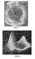
- FIG. 2is a reproduction of a three-dimensional thickness map of the articular cartilage of the distal femur.
- Three-dimensional thickness mapscan be generated, for example, from ultrasound, CT or MRI data. Dark holes within the substances of the cartilage indicate areas of full thickness cartilage loss.
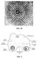
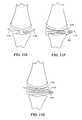
- FIG. 3 Ashows an example of a Placido disc of concentrically arranged circles of light.
- FIG. 3 Bshows an example of a projected Placido disc on a surface of fixed curvature.
- FIG. 4shows a reflection resulting from a projection of concentric circles of light (Placido Disk) on each femoral condyle, demonstrating the effect of variation in surface contour on the reflected circles.
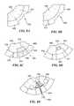
- FIG. 5shows an example of a 2D topographical map of an irregularly curved surface.
- FIG. 6shows an example of a 3D topographical map of an irregularly curved surface.
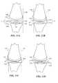
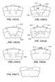
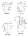
- FIGS. 7 A - Hillustrate, in cross-section, various stages of knee resurfacing.
- FIG. 7 Ashows an example of normal thickness cartilage and a cartilage defect.
- FIG. 7 Bshows an imaging technique or a mechanical, optical, laser or ultrasound device measuring the thickness and detecting a sudden change in thickness indicating the margins of a cartilage defect.
- FIG. 7 Cshows a weight-bearing surface mapped onto the articular cartilage.
- FIG. 7 Dshows an intended implantation site and cartilage defect.
- FIG. 7 Edepicts placement of an exemplary single component articular surface repair system.
- FIG. 7 Fshows an exemplary multi-component articular surface repair system.
- FIG. 7 Gshows an exemplary single component articular surface repair system.
- FIG. 7 Hshows an exemplary multi-component articular surface repair system.
- FIGS. 8 A - Eillustrate, in cross-section, exemplary knee imaging and resurfacing.
- FIG. 8 Ashows a magnified view of an area of diseased cartilage.
- FIG. 8 Bshows a measurement of cartilage thickness adjacent to the defect.
- FIG. 8 Cdepicts placement of a multi-component mini-prosthesis for articular resurfacing.
- FIG. 8 Dis a schematic depicting placement of a single component mini-prosthesis utilizing stems or pegs.
- FIG. 8 Edepicts placement of a single component mini-prosthesis utilizing stems and an opening for injection of bone cement.
- FIGS. 9 A - Cillustrate, in cross-section, other exemplary knee resurfacing devices and methods.
- FIG. 9 Adepicts normal thickness cartilage in the anterior and central and posterior portion of a femoral condyle and a large area of diseased cartilage in the posterior portion of the femoral condyle.
- FIG. 9 Bdepicts placement of a single component articular surface repair system.
- FIG. 9 Cdepicts a multi-component articular surface repair system.
- FIGS. 10 A - Bare flow charts illustrating steps for forming a device in situ.
- FIGS. 11 A - Gillustrate, in cross-section, the use of an inflation device to form an implant.
- FIG. 11 Aillustrates a single lumen balloon inserted between two joint surfaces where the inflation occurs within the bounds of the joint.
- FIG. 11 Billustrates another single lumen balloon inserted between two joint surfaces where the inflatable surfaces extend beyond a first and second edge of a joint.
- FIG. 11 Cillustrates another single lumen balloon between two joint surfaces.
- FIG. 11 Dillustrates a multi-balloon solution using two balloons where the balloons are adjacent to each other within the joint.
- FIG. 11 Eillustrates an alternative multi-balloon solution wherein a first balloon is comprised within a second balloon.
- FIG. 11 Aillustrates a single lumen balloon inserted between two joint surfaces where the inflation occurs within the bounds of the joint.
- FIG. 11 Billustrates another single lumen balloon inserted between two joint surfaces where the inflatable surfaces extend beyond a first and second edge of a joint.
- FIG. 11 Cillustrates another single
- FIG. 11 Fillustrates another multi-balloon solution where a first balloon lies within the lumen of a second balloon and further wherein the second balloon is adjacent a third balloon.
- FIG. 11 Gillustrates a 3 balloon configuration wherein a first balloon lies adjacent a second balloon and a third balloon fits within the lumen of one of the first or second balloon.
- FIGS. 12 A - Eillustrate a variety of cross-sectional shapes achieved using balloons with variable wall thicknesses or material compositions.
- the inflation deviceenables the implant to achieve a surface conforming to the irregularities of the joint surface.
- the inflation deviceenables the implant to achieve a surface that sits above the irregular joint surface;
- FIG. 12 Cillustrates a device formed where a central portion of the device sits above the joint surface irregularities while the proximal and distal ends illustrated form a lateral abutting surface to the joint defects.
- FIG. 12 Dillustrates a device formed using a first inflation device within a second inflation device, with an exterior configuration similar to that shown in FIG. 12 A ; while FIG. 12 E illustrates an alternative device formed using at least two different inflation devices having an exterior shape similar to the device shown in FIG. 12 C.
- FIGS. 13 A - J( 1 - 3 ) show a variety of cross-sectional views of the inflation devices shown in FIGS. 11 and 12 taken at a position perpendicular to the views shown in FIGS. 11 and 12 .
- FIGS. 14 A - Jillustrate the use of a retaining device to form an implant in situ.
- FIGS. 14 A and 14 Dillustrate a cartilage defect on an articular surface in the sagittal plane (S) and the coronal plane (C).
- FIGS. 14 B and 14 Eillustrate a cartilage defect on an articular surface in the sagittal plane (S) and the coronal plane (C) with smooth margins optionally created by the surgeon.
- FIGS. 14 C and 14 Fillustrate a cartilage defect on an articular surface in the sagittal plane (S) and the coronal plane (C) with a retaining device defining a cavity.
- FIG. 14 G( 1 - 9 ) illustrate a bone surface of the bone that can be prepared to define small teeth, holes, or anchoring members.
- FIG. 14 Hillustrates the use of a circumferential ridge.
- FIG. 14 Iillustrates a retaining mold with a handle placed on the surface of a bone.
- FIG. 14 Jillustrates a retaining device with one or more attached handles.
- FIGS. 15 A - Bshow single and multiple component devices.
- FIG. 15 Ashows an exemplary single component articular surface repair system with varying curvature and radii.
- FIG. 15 Bdepicts a multi-component articular surface repair system with a second component that mirrors the shape of the subchondral bone and a first component closely matches the shape and curvature of the surrounding normal cartilage.
- FIGS. 16 A - Bshow exemplary articular repair systems having an outer contour matching the surrounding normal cartilage. The systems are implanted into the underlying bone using one or more pegs.
- FIG. 16 Aillustrates one embodiment of the articular system affixed to subchondral bone
- FIG. 16 Billustrates an alternative affixing or anchoring mechanism.
- FIG. 17shows a perspective view of an exemplary articular repair device including a flat surface to control depth and prevent toggle; an exterior surface having the contour of normal cartilage; flanges to prevent rotation and control toggle; a groove to facilitate tissue in-growth.
- FIGS. 18 A - Ddepict, in cross-section, another example of an implant with multiple anchoring pegs.
- FIG. 18 B - Dshow various cross-sectional representations of the pegs: FIG. 18 B shows a peg having a groove;
- FIG. 18 Cshows a peg with radially-extending arms that help anchor the device in the underlying bone
- FIG. 18 Dshows a peg with multiple grooves or flanges.
- FIGS. 19 A - Bdepict an overhead view of an exemplary implant with multiple anchoring pegs and depict how the pegs are not necessarily linearly aligned along the longitudinal axis of the device.
- FIG. 19 A and FIG. 19 Bshow different numbers of anchoring pegs and alternative positions of the pegs relative to the longitudinal axis of the device.
- FIGS. 20 A - Edepict an exemplary implant having radially extending arms.
- FIG. 20 Adepicts an implant with a peg having radially extending arms.
- FIGS. 20 B - Eare overhead views of the implant illustrating a variety of suitable alternative shapes showing that the shape of the peg need not be conical.
- FIG. 21 Aillustrates a femur, tibia and fibula along with the mechanical and anatomic axes.
- FIGS. 21 B - Eillustrate the tibia with the anatomic and mechanical axis used to create a cutting plane along with a cut femur and tibia.
- FIG. 21 Billustrates a normal knee wherein the line corresponding to the surface of the joint is parallel to the resection line.
- FIG. 21 Cillustrates a varus knee wherein the line corresponding to the surface of the joint is not parallel to the resection line.
- FIG. 21 Dillustrates a valgus knee wherein the line corresponding to the surface of the joint is not parallel to the resection line.
- FIG. 21 Eillustrates a resected femur to provide flat surfaces that communicate with the interior of the femoral prosthesis.
- FIG. 21 Fillustrates the proximal end of the femur including the head of the femur.
- FIG. 22shows an example of a surgical tool having one surface matching the geometry of an articular surface of the joint. Also shown is an aperture in the tool capable of controlling drill depth and width of the hole and allowing implantation of an insertion of implant having a press-fit design.
- FIG. 23is a flow chart depicting various methods of the invention used to create a mold for preparing a patient's joint for arthroscopic surgery.
- FIG. 24 Adepicts, in cross-section, an example of a surgical tool containing an aperture through which a surgical drill or saw can fit.
- the apertureguides the drill or saw to make the proper hole or cut in the underlying bone.
- Dotted linesrepresent where the cut corresponding to the aperture will be made in bone.
- FIG. 24 Bdepicts, in cross-section, an example of a surgical tool containing apertures through which a surgical drill or saw can fit and which guide the drill or saw to make cuts or holes in the bone. Dotted lines represent where the cuts corresponding to the apertures will be made in bone.
- FIGS. 25 A - Qillustrate tibial cutting blocks and molds used to create a surface perpendicular to the anatomic axis for receiving the tibial portion of a knee implant.
- FIG. 25 Aillustrates a tibial cutting block in conjunction with a tibia that has not been resected.
- FIGS. 25 B - Dshow a variety of views of ae removable exterior piece.
- FIG. 25 Bshows a side view of a removable exterior piece.
- FIG. 25 Cshows a top view of the removable exterior piece.
- FIG. 25 Dshows another side view of the removable exterior piece.
- FIGS. 25 E - Hillustrate the interior, patient specific, piece from a variety of perspectives.
- FIG. 25 Eshows a side view of the piece.
- FIG. 25 Eshows a side view of the piece.
- FIG. 25 Fillustrates a superior view of the interior, patient, specific piece of the mold.
- FIG. 25 Gillustrates an inferior view of the piece.
- FIG. 25 Hillustrates cross-sectional views of the interior patient specific mold piece.
- FIG. 25 Idepicts an embodiment of an aperture.
- FIG. 25 J and FIG. 25 Mdepict alternative embodiments of the invention designed to control the movement and rotation of a cutting block relative to a mold.
- FIG. 25 Kdepicts a curved slot that enables rotational adjustment.
- FIG. 25 Ldepicts another embodiment that enables rotational adjustment in or within a recess that conforms in shape to a peg.
- FIG. 25 Mdepicts another configuration of a surface of a mold.
- FIG. 25 Nillustrates an alternative design of a cutting block.
- FIG. 25 Oillustrates a cross-section of a cutting block system.
- FIG. 25 P and FIG. 25 Qillustrate a device configured to cover half of a tibial plateau such that it is unicompart
- FIGS. 26 A - Oillustrate femur cutting blocks and molds used to create a surface for receiving the femoral portion of a knee implant.
- FIG. 26 Aillustrates a femur with a first portion of a mold placed thereon.
- FIG. 26 Billustrates a side view of the first portion from the perspective of a side surface illustrating an aperture.
- FIG. 26 Cillustrates another side view of the first, patient specific molded portion.
- FIG. 26 Dillustrates a top view of the first portion.
- FIG. 26 Eillustrates the femur with a first portion of the cutting block placed on the femur and a second, exterior, portion placed over the first portion.
- FIG. 26 Fillustrates a side view of the second, exterior, cutting block portion.
- FIG. 26 Aillustrates a femur with a first portion of a mold placed thereon.
- FIG. 26 Billustrates a side view of the first portion from the perspective of a side surface illustrating an aperture.
- FIG. 26 Gis another side view of the second, exterior, portion.
- FIG. 26 His a top view of the second, exterior portion.
- FIG. 26 Iillustrates a spacer for use between the first portion and the second portion.
- FIG. 26 Jshows optional grooves or channels to accommodate, for example, pins.
- FIG. 26 Kshows a configuration of the surface of the mold with slots that enable rotational adjustment.
- FIGS. 26 L and 26 Mshow alternative designs that can be used to control the movement and rotation of the cutting block relative to the mold.
- FIGS. 26 N (sagittal view) and 26 O (coronal view)and illustrate the interior surface of the mold.
- FIGS. 27 A - Gillustrate patellar cutting blocks and molds used to prepare the patella for receiving a portion of a knee implant.
- FIGS. 27 A - Cillustrates the patellar cutting block in conjunction with a patella that has not been resected.
- FIG. 27 Ais a view in the sagittal plane S.
- FIG. 27 Bis a view in the axial plane A.
- FIG. 27 Cis a frontal view F of the mold demonstrating the opening for the saw.
- FIG. 27 D (sagittal view) and FIG. 27 E (axial view)illustrate a patellar cutting block in conjunction with a patella that has not been resected.
- FIG. 27 Fshows an embodiment of a grasper with an opening.
- FIG. 26 Gshows an embodiment of a patella clamp.
- FIGS. 28 A - Hillustrate femoral head cutting blocks and molds used to create a surface for receiving the femoral portion of a knee implant.
- FIG. 28 Aillustrates a femur with a mold and cutting block system placed to provide a cutting plane across the femoral neck.
- FIG. 28 Billustrates a top view of the cutting block system.
- FIG. 28 Cillustrates a second cutting block system that can be placed over the cut femur to provide a guide for reaming after the femoral head has been removed using the cutting block shown in FIG. 28 A .
- FIG. 28 Dis a top view of the cutting block shown in FIG. 28 C .
- FIG. 28 E and FIG. 28 Fillustrate different configurations of the aperture.
- FIG. 28 G and FIG. 28Hillustrate alternative designs of the cutting block system with ( 28 G ) or without a handle ( 28 H ).
- FIGS. 29 A - Dillustrate acetabulum cutting blocks and molds used to create a surface for a hip implant.
- FIGS. 29 A(sagittal view) and 29 B (frontal view, down onto mold) illustrates a mold system for the acetabulum.
- FIG. 29 Cis a frontal view of the same mold system shown in FIGS. 29A and 29B with the additional feature of a groove.
- FIG. 29 Dillustrates a cross-section of a system where the interior surface of the molded section has teeth or grooves to facilitate grasping the neck of the femur.
- the practice of the present inventionemploys, unless otherwise indicated, conventional methods of x-ray imaging and processing, x-ray tomosynthesis, ultrasound including A-scan, B-scan and C-scan, computed tomography (CT scan), magnetic resonance imaging (MRI), optical coherence tomography, single photon emission tomography (SPECT) and positron emission tomography (PET) within the skill of the art.
- CT scancomputed tomography
- MRImagnetic resonance imaging
- SPECTsingle photon emission tomography
- PETpositron emission tomography
- the present inventionprovides methods and compositions for repairing joints, particularly for repairing articular cartilage and for facilitating the integration of a wide variety of cartilage repair materials into a subject.
- the techniques described hereinallow for the customization of cartilage repair material to suit a particular subject, for example in terms of size, cartilage thickness and/or curvature.
- shapee.g., size, thickness and/or curvature
- the success of repairis enhanced.
- the repair materialcan be shaped prior to implantation and such shaping can be based, for example, on electronic images that provide information regarding curvature or thickness of any “normal” cartilage surrounding the defect and/or on curvature of the bone underlying the defect.
- the current inventionprovides, among other things, for minimally invasive methods for partial joint replacement. The methods will require only minimal or, in some instances, no loss in bone stock. Additionally, unlike with current techniques, the methods described herein will help to restore the integrity of the articular surface by achieving an exact or near anatomic match between the implant and the surrounding or adjacent cartilage and/or subchondral bone.
- Advantages of the present inventioncan include, but are not limited to, (i) customization of joint repair, thereby enhancing the efficacy and comfort level for the patient following the repair procedure; (ii) eliminating the need for a surgeon to measure the defect to be repaired intraoperatively in some embodiments; (iii) eliminating the need for a surgeon to shape the material during the implantation procedure; (iv) providing methods of evaluating curvature of the repair material based on bone or tissue images or based on intraoperative probing techniques; (v) providing methods of repairing joints with only minimal or, in some instances, no loss in bone stock; and (vi) improving postoperative joint congruity.
- the methods described hereinallow for the design and use of joint repair material that more precisely fits the defect (e.g., site of implantation) and, accordingly, provides improved repair of the joint.
- the methods and compositions described hereincan be used to treat defects resulting from disease of the cartilage (e.g., osteoarthritis), bone damage, cartilage damage, trauma, and/or degeneration due to overuse or age.
- the inventionallows, among other things, a health practitioner to evaluate and treat such defects.
- the size, volume and shape of the area of interestcan include only the region of cartilage that has the defect, but preferably will also include contiguous parts of the cartilage surrounding the cartilage defect.
- size, curvature and/or thickness measurementscan be obtained using any suitable technique.
- one-dimensional, two-dimensional, and/or three-dimensional measurementscan be obtained using suitable mechanical means, laser devices, electromagnetic or optical tracking systems, molds, materials applied to the articular surface that harden and “memorize the surface contour,” and/or one or more imaging techniques known in the art. Measurements can be obtained non-invasively and/or intraoperatively (e.g., using a probe or other surgical device).
- the thickness of the repair devicecan vary at any given point depending upon the depth of the damage to the cartilage and/or bone to be corrected at any particular location on an articular surface.
- the processbegins by first measuring the size of the area of diseased cartilage or cartilage loss 10 . Thereafter the user can optionally measure the thickness of adjacent cartilage 20 . Once these steps are performed, the curvature of the articular surface is measured 30 . Alternatively, the curvature of subchondral bone can be measured.
- an implantcan be selected from a library 32 or an implant can be generated based on the patient specific parameters obtained in the measurements and evaluation 34 .
- the implantation siteis prepared 40 and then the implant is installed 42 .
- One or more of these stepscan be repeated as necessary or desired as shown by the optional repeat steps 11 , 21 , 31 , 33 , 35 , and 41 .
- imaging techniques suitable for measuring thickness and/or curvature (e.g., of cartilage and/or bone) or size of areas of diseased cartilage or cartilage lossinclude the use of x-rays, magnetic resonance imaging (MRI), computed tomography scanning (CT, also known as computerized axial tomography or CAT), optical coherence tomography, ultrasound imaging techniques, and optical imaging techniques.
- MRImagnetic resonance imaging
- CTcomputed tomography scanning
- CATcomputerized axial tomography
- optical coherence tomographyoptical coherence tomography
- ultrasound imaging techniquesand optical imaging techniques.
- Contrast or other enhancing agentscan be employed using any route of administration, e.g. intravenous, intra-articular, etc.
- CT or MRIis used to assess tissue, bone, cartilage and any defects therein, for example cartilage lesions or areas of diseased cartilage, to obtain information on subchondral bone or cartilage degeneration and to provide morphologic or biochemical or biomechanical information about the area of damage.
- changessuch as fissuring, partial or full thickness cartilage loss, and signal changes within residual cartilage can be detected using one or more of these methods.
- MRIincluding conventional T1 and T2-weighted spin-echo imaging, gradient recalled echo (GRE) imaging, magnetization transfer contrast (MTC) imaging, fast spin-echo (FSE) imaging, contrast enhanced imaging, rapid acquisition relaxation enhancement (RARE) imaging, gradient echo acquisition in the steady state (GRASS), and driven equilibrium Fourier transform (DEFT) imaging, to obtain information on cartilage, see Alexander, et al., WO 02/22014.
- GREgradient recalled echo
- MTCmagnetization transfer contrast
- FSEfast spin-echo
- RARErapid acquisition relaxation enhancement
- GASSgradient echo acquisition in the steady state
- DEFTdriven equilibrium Fourier transform
- the measurements producedare based on three-dimensional images of the joint obtained as described in Alexander, et al., WO 02/22014 or sets of two-dimensional images ultimately yielding 3D information.
- Two-dimensional, and three-dimensional images, or maps, of the cartilage alone or in combination with a movement pattern of the joint, e.g. flexion-extension, translation and/or rotation,can be obtained.
- Three-dimensional imagescan include information on movement patterns, contact points, contact zone of two or more opposing articular surfaces, and movement of the contact point or zone during joint motion.
- Two- and three-dimensional imagescan include information on biochemical composition of the articular cartilage.
- imaging techniquescan be compared over time, for example to provide up-to-date information on the shape and type of repair material needed.
- imaging techniquescan be combined, if desired.
- C-arm imaging or x-ray fluoroscopycan be used for motion imaging, while MRI can yield high resolution cartilage information.
- C-arm imagingcan be combined with intra-articular contrast to visualize the cartilage.
- FIG. 2illustrates a reproduction of a three-dimensional thickness map of the articular surface on the distal femur.
- the dark holes within the cartilageindicate areas of full cartilage loss.
- Imagingcan be used to determine the anatomical and biomechanical axes of an extremity associated with a joint. Suitable tests include, for example, an x-ray, or an x-ray combined with an MRI. Typically, anatomical landmarks are identified on the imaging test results (e.g., the x-ray film) and those landmarks are then utilized to directly or indirectly determine the desired axes. Thus, for example, if surgery is contemplated in a hip joint, knee joint, or ankle joint, an x-ray can be obtained. This x-ray can be a weight-bearing film of the extremity, for example, a full-length leg film taken while the patient is standing.
- This filmcan be used to determine the femoral and tibial anatomical axes and to estimate the biomechanical axes.
- these processes for identifying, e.g., anatomical and biomechanical axis of the jointcan be applied to other joints without departing from the scope of the invention.
- Anatomical and biomechanical axescan also be determined using other imaging modalities, including but not limited to, computed tomography and MRI.
- a CT scancan be obtained through the hip joint, the knee joint, and the ankle joint.
- the scancan be reformatted in the sagittal, coronal, or other planes.
- the CT imagescan then be utilized to identify anatomical landmarks and to determine the anatomical and biomechanical axes of the hip joint, knee joint, and/or ankle joint.
- an MRI scancan be obtained for this purpose.
- an MRI scan of the thigh and pelvic regioncan be obtained using a body coil or a torso phased array coil.
- a high resolution scan of the knee jointcan be obtained using a dedicated extremity coil.
- a scan of the calf/tibia region and the ankle jointcan be obtained again using a body coil or a torso phased array coil.
- Anatomical landmarkscan be identified in each joint on these scans and the anatomical and biomechanical axes can be estimated using this information.
- An imaging test obtained during weight-bearing conditionshas some inherent advantages, in that it demonstrates normal as well as pathological loading and load distribution.
- a cross-sectional imaging study such as a CT scan or MRI scanhas some advantages because it allows one to visualize and demonstrate the anatomical landmarks in three, rather than two, dimensions, thereby adding accuracy.
- measurementscan be performed in other planes, such as the sagittal or oblique planes, that may not be easily accessible in certain anatomical regions using conventional radiography. In principle, any imaging test can be utilized for this purpose.
- the biomechanical axiscan be defined as the axis going from the center of the femoral head, between the condylar surfaces and through the ankle joint.
- Computed Tomography imaginghas been shown to be highly accurate for the determination of the relative anatomical and biomechanical axes of the leg (Testi Debora, Zannoni Cinzia, Cappello Angelo and Viceconti Marco. “Border tracing algorithm implementation for the femoral geometry reconstruction.” Comp. Meth. and Programs in Biomed ., Feb. 14, 2000; Farrar M J, Newman R J, Mawhinney R R, King R. “Computed tomography scan scout film for measurement of femoral axis in knee arthroplasty.” J. Arthroplasty. 1999 December; 14(8): 1030-1; Kim J S, Park T S, Park S B, Kim J S, Kim I Y, Kim S I.
- angles of the anatomical structures of the proximal and distal femuralso show a certain variability level (i.e. standard deviation) comparable with the varus or valgus angle or the angle between the anatomical femoral axis and the biomechanical axis (Mahaisavariya B, Sitthiseripratip K, Tongdee T, Bohez E, Sloten J V, Oris P. “Morphological study of the proximal femur: a new method of geometrical assessment using 3 dimensional reverse engineering.” Med. Eng. and Phys. 24 (2002) 617-622).
- a preferred approach for assessing the axesis based on CT scans of the hip, knee and ankle joint or femur rather than only of the knee region.
- CThas been shown to be efficient in terms of the contrast of the bone tissue with respect to surrounding anatomical tissue so the bone structures corresponding to the femur and tibia can be extracted very accurately with semi automated computerized systems (Mahaisavariya B, Sitthiseripratip K, Tongdee T, Bohez E, Sloten J V, Oris P. “Morphological study of the proximal femur: a new method of geometrical assessment using 3 dimensional reverse engineering.” Med. Eng. and Phys. 24 (2002) 617-622; Testi Debora, Zannoni Cinzia, Cappello Angelo and Viceconti Marco. “Border tracing algorithm implementation for the femoral geometry reconstruction.” Comp. Meth. and Programs in Biomed ., Feb. 14, 2000).
- Part 13D imaging method. Medical and Biological engineering and computing. 38(6): 603-609, November 2000; Kim J S, Park T S, Park S B, Kim J S, Kim I Y, Kim S I. Measurement of femoral neck anteversion in 3D.
- Part 13D modeling method. Medical and Biological engineering and computing. 38(6): 610-616, November 2000).
- Farrarused simple CT 2-D scout views to estimate the femoral axis (Farrar M J, Newman R J, Mawhinney R R, King R. Computed tomography scan scout film for measurement of femoral axis in knee arthroplasty. J. Arthroplasty. 1999 December; 14(8): 1030-1).
- 2-D sagittal and coronal reconstructions of CT slice imagesare used to manually estimate the biomechanical axis.
- One skilled in the artcan easily recognize many different ways to automate this process. For example, a CT scan covering at least the hip, knee and ankle region is acquired. This results in image slices (axial) which can be interpolated to generate the sagittal and coronal views.
- Preprocessing (filtering) of the slice imagescan be used to improve the contrast of the bone regions so that they can be extracted accurately using simple thresholding or a more involved image segmentation tool like LiveWire or active contour models.
- the biomechanical axiscan be defined as the line connecting the proximal and the distal centroids, i.e. the femoral head centroid, the tibial or ankle joint centroid.
- the position of the intercondylar notchcan be used for evaluation of possible deviations, errors or deformations including varus and valgus deformity.
- multiple imaging testscan be combined.
- the anatomical and biomechanical axescan be estimated using a weight-bearing x-ray of the extremity or portions of the extremity.
- the anatomical information derived in this fashioncan then be combined with a CT or MRI scan of one or more joints, such as a hip, knee, or ankle joint.
- Landmarks seen on radiographycan then, for example, be cross-referenced on the CT or MRI scan.
- Axis measurements performed on radiographycan be subsequently applied to the CT or MRI scans or other imaging modalities.
- the information obtained from a CT scancan be compared with that obtained with an MRI or ultrasound scan.
- image fusion of different imaging modalitiescan be performed.
- a full-length weight-bearing x-ray of the lower extremitycan be obtained.
- Thiscan be supplemented by a spiral CT scan, optionally with intra-articular contrast of the knee joint providing high resolution three-dimensional anatomical characterization of the knee anatomy even including the menisci and cartilage.
- This information, along with the axis information provided by the radiographcan be utilized to select or derive therapies, such as implants or surgical instruments.
- a CT scanpreferably a spiral CT scan of one or more joints.
- the spiral CT scancan optionally be performed using intra-articular contrast.
- an MRI scancan be performed. If CT is utilized, a full spiral scan, or a few selected slices, can be obtained through neighboring joints. Typically, a full spiral scan providing full three-dimensional characterization would be obtained in the joint for which therapy is contemplated. If implants, or molds, for surgical instruments are selected or shaped, using this scan, the subchondral bone shape can be accurately determined from the resultant image data.
- a standard cartilage thickness and, similarly, a standard cartilage losscan be assumed in certain regions of the articular surface.
- a standard thickness of 2 mm of the articular cartilagecan be applied to the subchondral bone in the anterior third of the medial and lateral femoral condyles.
- a standard thickness of 2 mm of the articular cartilagecan be applied to the subchondral bone in the posterior third of the medial and lateral femoral condyles.
- a standard thickness of 0 mm of the articular cartilagecan be applied in the central weight-bearing zone of the medial condyle, and a different value can be applied to the lateral condyle.
- the transition between these zonescan be gradual, for example, from 2 mm to 0 mm.
- These standard values of estimated cartilage thickness and cartilage loss in different regions of the jointcan optionally be derived from a reference database.
- the reference databasecan include categories such as age, body mass index (“BMI”), severity of disease, pain, severity of varus deformity, severity of valgus deformity, Kellgren-Lawrence score, along with other parameters that are determined to be relative and useful.
- BMIbody mass index
- Use of a standard thickness for the articular cartilagecan facilitate the imaging protocols required for pre-operative planning.
- the articular cartilagecan be fully characterized by performing a spiral CT scan of the joint in the presence of intra-articular contrast or by performing an MRI scan using cartilage sensitive pulse sequences.
- the techniques described hereincan be used to obtain an image of a joint that is stationary, either weight bearing or not, or in motion or combinations thereof. Imaging studies that are obtained during joint motion can be useful for assessing the load bearing surface. This can be advantageous for designing or selecting implants, e.g. for selecting reinforcements in high load areas, for surgical tools and for implant placement, e.g. for optimizing implant alignment relative to high load areas.
- measurements of the size of an area of diseased cartilage or an area of cartilage loss, measurements of cartilage thickness and/or curvature of cartilage or bonecan be obtained intraoperatively during arthroscopy or open arthrotomy. Intraoperative measurements can, but need not, involve actual contact with one or more areas of the articular surfaces.
- Devices suitable for obtaining intraoperative measurements of cartilage or bone or other articular structures, and to generate a topographical map of the surfaceinclude but are not limited to, Placido disks and laser interferometers, and/or deformable materials or devices.
- Placido disks and laser interferometersSee, for example, U.S. Pat. Nos. 6,382,028 to Wooh et al., issued May 7, 2002; 6,057,927 to Levesque et al., issued May 2, 2000; 5,523,843 to Yamane et al. issued Jun. 4, 1996; 5,847,804 to Sarver et al. issued Dec. 8, 1998; and 5,684,562 to Fujieda, issued Nov. 4, 1997).
- FIG. 3 Aillustrates a Placido disk of concentrically arranged circles of light.
- the concentric arrays of the Placido diskproject well-defined circles of light of varying radii, generated either with laser or white light transported via optical fiber.
- the Placido diskcan be attached to the end of an endoscopic device (or to any probe, for example a hand-held probe) so that the circles of light are projected onto the cartilage surface.
- FIG. 3 Billustrates an example of a Placido disk projected onto the surface of a fixed curvature.
- One or more imaging camerascan be used (e.g., attached to the device) to capture the reflection of the circles.
- Mathematical analysisis used to determine the surface curvature.
- the curvaturecan then, for example, be visualized on a monitor as a color-coded, topographical map of the cartilage surface. Additionally, a mathematical model of the topographical map can be used to determine the ideal surface topography to replace any cartilage defects in the area analyzed.
- FIG. 4shows a reflection resulting from the projection of concentric circles of light (Placido disk) on each femoral condyle, demonstrating the effect of variation in surface contour on reflected circles.
- a laser interferometercan also be attached to the end of an endoscopic device.
- a small sensorcan be attached to the device in order to determine the cartilage surface or bone curvature using phase shift interferometry, producing a fringe pattern analysis phase map (wave front) visualization of the cartilage surface.
- the curvaturecan then be visualized on a monitor as a color coded, topographical map of the cartilage surface.
- a mathematical model of the topographical mapcan be used to determine the ideal surface topography to replace any cartilage or bone defects in the area analyzed. This computed, ideal surface, or surfaces, can then be visualized on the monitor, and can be used to select the curvature, or curvatures, of the replacement cartilage.
- Mechanical devicescan also be used for intraoperative measurements, for example, deformable materials such as gels, molds, any hardening materials (e.g., materials that remain deformable until they are heated, cooled, or otherwise manipulated).
- deformable materialssuch as gels, molds, any hardening materials (e.g., materials that remain deformable until they are heated, cooled, or otherwise manipulated).
- a deformable gelcan be applied to a femoral condyle. The side of the gel pointing towards the condyle can yield a negative impression of the surface contour of the condyle. The negative impression can then be used to determine the size of a defect, the depth of a defect and the curvature of the articular surface in and adjacent to a defect.
- This informationcan be used to select a therapy, e.g. an articular surface repair system.
- a hardening materialcan be applied to an articular surface, e.g. a femoral condyle or a tibial plateau. The hardening material can remain on the articular surface until hardening has occurred. The hardening material can then be removed from the articular surface. The side of the hardening material pointing towards the articular surface can yield a negative impression of the articular surface. The negative impression can then be used to determine the size of a defect, the depth of a defect and the curvature of the articular surface in and adjacent to a defect.
- This informationcan then be used to select a therapy, e.g. an articular surface repair system.
- the hardening systemcan remain in place and form the actual articular surface repair system.
- the deformable materialcomprises a plurality of individually moveable mechanical elements.
- each elementWhen pressed against the surface of interest, each element can be pushed in the opposing direction and the extent to which it is pushed (deformed) can correspond to the curvature of the surface of interest.
- the devicecan include a brake mechanism so that the elements are maintained in the position that conforms to the surface of the cartilage and/or bone. The device can then be removed from the patient and analyzed for curvature.
- each individual moveable elementcan include markers indicating the amount and/or degree it is deformed at a given spot.
- a cameracan be used to intra-operatively image the device and the image can be saved and analyzed for curvature information. Suitable markers include, but are not limited to, actual linear measurements (metric or empirical), different colors corresponding to different amounts of deformation and/or different shades or hues of the same color(s). Displacement of the moveable elements can also be measured using electronic means.
- Other devices to measure cartilage and subchondral bone intraoperativelyinclude, for example, ultrasound probes.
- An ultrasound probepreferably handheld, can be applied to the cartilage and the curvature of the cartilage and/or the subchondral bone can be measured. Moreover, the size of a cartilage defect can be assessed and the thickness of the articular cartilage can be determined.
- Such ultrasound measurementscan be obtained in A-mode, B-mode, or C-mode. If A-mode measurements are obtained, an operator can typically repeat the measurements with several different probe orientations, e.g. mediolateral and anteroposterior, in order to derive a three-dimensional assessment of size, curvature and thickness.
- the probesare preferably handheld.
- the probes or at least a portion of the probe, typically the portion that is in contact with the tissuecan be sterile. Sterility can be achieved with use of sterile covers, for example similar to those disclosed in WO 99/08598A1 to Lang, published Feb. 25, 1999.
- Analysis on the curvature of the articular cartilage or subchondral bone using imaging tests and/or intraoperative measurementscan be used to determine the size of an area of diseased cartilage or cartilage loss.
- the curvaturecan change abruptly in areas of cartilage loss.
- Such abrupt or sudden changes in curvaturecan be used to detect the boundaries of diseased cartilage or cartilage defects.
- measurementscan be made while the joint is stationary, either weight bearing or not, or in motion.
- a wide variety of materialsfind use in the practice of the present invention, including, but not limited to, plastics, metals, crystal free metals, ceramics, biological materials (e.g., collagen or other extracellular matrix materials), hydroxyapatite, cells (e.g., stem cells, chondrocyte cells or the like), or combinations thereof.
- a repair materialcan be formed or selected. Further, using one or more of these techniques described herein, a cartilage replacement or regenerating material having a curvature that will fit into a particular cartilage defect, will follow the contour and shape of the articular surface, and will match the thickness of the surrounding cartilage.
- the repair materialcan include any combination of materials, and typically include at least one non-pliable material, for example materials that are not easily bent or changed.
- joint repair systemsoften employ metal and/or polymeric materials including, for example, prostheses which are anchored into the underlying bone (e.g., a femur in the case of a knee prosthesis).
- metal and/or polymeric materialsincluding, for example, prostheses which are anchored into the underlying bone (e.g., a femur in the case of a knee prosthesis).
- a femurin the case of a knee prosthesis.
- a wide-variety of metalsare useful in the practice of the present invention, and can be selected based on any criteria. For example, material selection can be based on resiliency to impart a desired degree of rigidity.
- Non-limiting examples of suitable metalsinclude silver, gold, platinum, palladium, iridium, copper, tin, lead, antimony, bismuth, zinc, titanium, cobalt, stainless steel, nickel, iron alloys, cobalt alloys, such as Elgiloy®, a cobalt-chromium-nickel alloy, and MP35N, a nickel-cobalt-chromium-molybdenum alloy, and NitinolTM, a nickel-titanium alloy, aluminum, manganese, iron, tantalum, crystal free metals, such as Liquidmetal® alloys (available from LiquidMetal Technologies, www.liquidmetal.com), other metals that can slowly form polyvalent metal ions, for example to inhibit calcification of implanted substrates in contact with a patient's bodily fluids or tissues, and combinations thereof.
- suitable metalsinclude silver, gold, platinum, palladium, iridium, copper, tin, lead, antimony, bismuth, zinc
- Suitable synthetic polymersinclude, without limitation, polyamides (e.g., nylon), polyesters, polystyrenes, polyacrylates, vinyl polymers (e.g., polyethylene, polytetrafluoroethylene, polypropylene and polyvinyl chloride), polycarbonates, polyurethanes, poly dimethyl siloxanes, cellulose acetates, polymethyl methacrylates, polyether ether ketones, ethylene vinyl acetates, polysulfones, nitrocelluloses, similar copolymers and mixtures thereof.
- polyamidese.g., nylon
- polyesterse.g., polystyrenes
- polyacrylatese.g., polyethylene, polytetrafluoroethylene, polypropylene and polyvinyl chloride
- polycarbonatese.g., polycarbonates, polyurethanes, poly dimethyl siloxanes, cellulose acetates, polymethyl methacrylates, polyether ether ketones, ethylene vinyl a
- Bioresorbable synthetic polymerscan also be used such as dextran, hydroxyethyl starch, derivatives of gelatin, polyvinylpyrrolidone, polyvinyl alcohol, poly[N-(2-hydroxypropyl) methacrylamide], poly(hydroxy acids), poly(epsilon-caprolactone), polylactic acid, polyglycolic acid, poly(dimethyl glycolic acid), poly(hydroxy butyrate), and similar copolymers can also be used.
- PEEKTMpolyetheretherketone
- PEEK 450Gis an unfilled PEEK approved for medical implantation available from Victrex of Lancashire, Great Britain.
- Victrexis located at www.matweb.com or see Boedeker www.boedeker.com).
- Other sources of this materialinclude Gharda located in Panoli, India (www.ghardapolymers.com).
- the material selectedcan also be filled.
- other grades of PEEKare also available and contemplated, such as 30% glass-filled or 30% carbon filled, provided such materials are cleared for use in implantable devices by the FDA, or other regulatory body.
- Glass filled PEEKreduces the expansion rate and increases the flexural modulus of PEEK relative to that portion which is unfilled.
- the resulting productis known to be ideal for improved strength, stiffness, or stability.
- Carbon filled PEEKis known to enhance the compressive strength and stiffness of PEEK and lower its expansion rate. Carbon filled PEEK offers wear resistance and load carrying capability.
- thermoplastic or thermoplastic polycondensate materialsthat resist fatigue, have good memory, are flexible, and/or deflectable have very low moisture absorption, and good wear and/or abrasion resistance, can be used without departing from the scope of the invention.
- the implantcan also be comprised of polyetherketoneketone (PEKK).
- PEKpolyetherketone
- PEKEKKpolyetherketoneetherketoneketone
- PEEKKpolyetherketoneketone
- the polymerscan be prepared by any of a variety of approaches including conventional polymer processing methods.
- Preferred approachesinclude, for example, injection molding, which is suitable for the production of polymer components with significant structural features, and rapid prototyping approaches, such as reaction injection molding and stereo-lithography.
- the substratecan be textured or made porous by either physical abrasion or chemical alteration to facilitate incorporation of the metal coating. Other processes are also appropriate, such as extrusion, injection, compression molding and/or machining techniques.
- the polymeris chosen for its physical and mechanical properties and is suitable for carrying and spreading the physical load between the joint surfaces.
- More than one metal and/or polymercan be used in combination with each other.
- one or more metal-containing substratescan be coated with polymers in one or more regions or, alternatively, one or more polymer-containing substrate can be coated in one or more regions with one or more metals.
- the system or prosthesiscan be porous or porous coated.
- the porous surface componentscan be made of various materials including metals, ceramics, and polymers. These surface components can, in turn, be secured by various means to a multitude of structural cores formed of various metals.
- Suitable porous coatingsinclude, but are not limited to, metal, ceramic, polymeric (e.g., biologically neutral elastomers such as silicone rubber, polyethylene terephthalate and/or combinations thereof) or combinations thereof. See, e.g., U.S. Pat. No. 3,605,123 to Hahn, issued Sep. 20, 1971. U.S. Pat. No. 3,808,606 to Tronzo issued May 7, 1974 and U.S. Pat. No. 3,843,975 to Tronzo issued Oct.
- the coatingcan be applied by surrounding a core with powdered polymer and heating until cured to form a coating with an internal network of interconnected pores.
- the tortuosity of the porese.g., a measure of length to diameter of the paths through the pores
- the porous coatingcan be applied in the form of a powder and the article as a whole subjected to an elevated temperature that bonds the powder to the substrate. Selection of suitable polymers and/or powder coatings can be determined in view of the teachings and references cited herein, for example based on the melt index of each.
- Repair materialscan also include one or more biological material either alone or in combination with non-biological materials.
- any base materialcan be designed or shaped and suitable cartilage replacement or regenerating material(s) such as fetal cartilage cells can be applied to be the base.
- the cellscan be then be grown in conjunction with the base until the thickness (and/or curvature) of the cartilage surrounding the cartilage defect has been reached.
- Conditions for growing cellse.g., chondrocytes
- various substrates in culture, ex vivo and in vivoare described, for example, in U.S. Pat. Nos. 5,478,739 to Slivka et al. issued Dec. 26, 1995; 5,842,477 to Naughton et al. issued Dec.
- suitable substratesinclude plastic, tissue scaffold, a bone replacement material (e.g., a hydroxyapatite, a bioresorbable material), or any other material suitable for growing a cartilage replacement or regenerating material on it.
- a bone replacement materiale.g., a hydroxyapatite, a bioresorbable material
- Bio polymerscan be naturally occurring or produced in vitro by fermentation and the like. Suitable biological polymers include, without limitation, collagen, elastin, silk, keratin, gelatin, polyamino acids, cat gut sutures, polysaccharides (e.g., cellulose and starch) and mixtures thereof. Biological polymers can be bioresorbable.
- Biological materials used in the methods described hereincan be autografts (from the same subject); allografts (from another individual of the same species) and/or xenografts (from another species). See, also, International Patent Publications WO 02/22014 to Alexander et al. published Mar. 21, 2002 and WO 97/27885 to Lee published Aug. 7, 1997.
- autologous materialsare preferred, as they can carry a reduced risk of immunological complications to the host, including re-absorption of the materials, inflammation and/or scarring of the tissues surrounding the implant site.
- a probeis used to harvest tissue from a donor site and to prepare a recipient site.
- the donor sitecan be located in a xenograft, an allograft or an autograft.
- the probeis used to achieve a good anatomic match between the donor tissue sample and the recipient site.
- the probeis specifically designed to achieve a seamless or near seamless match between the donor tissue sample and the recipient site.
- the probecan, for example, be cylindrical.
- the distal end of the probeis typically sharp in order to facilitate tissue penetration. Additionally, the distal end of the probe is typically hollow in order to accept the tissue.
- the probecan have an edge at a defined distance from its distal end, e.g.
- the edgecan be external or can be inside the hollow portion of the probe.
- an orthopedic surgeoncan take the probe and advance it with physical pressure into the cartilage, the subchondral bone and the underlying marrow in the case of a joint such as a knee joint. The surgeon can advance the probe until the external or internal edge reaches the cartilage surface. At that point, the edge will prevent further tissue penetration thereby achieving a constant and reproducible tissue penetration.
- the distal end of the probecan include one or more blades, saw-like structures, or tissue cutting mechanism.
- the distal end of the probecan include an iris-like mechanism consisting of several small blades.
- the blade or bladescan be moved using a manual, motorized or electrical mechanism thereby cutting through the tissue and separating the tissue sample from the underlying tissue. Typically, this will be repeated in the donor and the recipient. In the case of an iris-shaped blade mechanism, the individual blades can be moved so as to close the iris thereby separating the tissue sample from the donor site.
- a laser device or a radiofrequency devicecan be integrated inside the distal end of the probe.
- the laser device or the radiofrequency devicecan be used to cut through the tissue and to separate the tissue sample from the underlying tissue.
- the same probecan be used in the donor and in the recipient.
- similarly shaped probes of slightly different physical dimensionscan be used.
- the probe used in the recipientcan be slightly smaller than that used in the donor thereby achieving a tight fit between the tissue sample or tissue transplant and the recipient site.
- the probe used in the recipientcan also be slightly shorter than that used in the donor thereby correcting for any tissue lost during the separation or cutting of the tissue sample from the underlying tissue in the donor material.
- Any biological repair materialcan be sterilized to inactivate biological contaminants such as bacteria, viruses, yeasts, molds, mycoplasmas and parasites. Sterilization can be performed using any suitable technique, for example radiation, such as gamma radiation.
- Any of the biological materials described hereincan be harvested with use of a robotic device.
- the robotic devicecan use information from an electronic image for tissue harvesting.
- the cartilage replacement materialhas a particular biochemical composition.
- the biochemical composition of the cartilage surrounding a defectcan be assessed by taking tissue samples and chemical analysis or by imaging techniques.
- WO 02/22014 to Alexanderdescribes the use of gadolinium for imaging of articular cartilage to monitor glycosaminoglycan content within the cartilage.
- the cartilage replacement or regenerating materialcan then be made or cultured in a manner, to achieve a biochemical composition similar to that of the cartilage surrounding the implantation site.
- the culture conditions used to achieve the desired biochemical compositionscan include, for example, varying concentrations.
- Biochemical composition of the cartilage replacement or regenerating materialcan, for example, be influenced by controlling concentrations and exposure times of certain nutrients and growth factors.
- a physical model of the surfaces of the articular cartilage and of the underlying bonecan be created.
- This physical modelcan be representative of a limited area within the joint or it can encompass the entire joint.
- the physical modelcan encompass only the medial or lateral femoral condyle, both femoral condyles and the notch region, the medial tibial plateau, the lateral tibial plateau, the entire tibial plateau, the medial patella, the lateral patella, the entire patella or the entire joint.
- the location of a diseased area of cartilagecan be determined, for example using a 3D coordinate system or a 3D Euclidian distance as described in WO 02/22014.
- the size of the defect to be repairedcan be determined.
- some, but not all, defectswill include less than the entire cartilage.
- the thickness of the normal or only mildly diseased cartilage surrounding one or more cartilage defectsis measured. This thickness measurement can be obtained at a single point or, preferably, at multiple points, for example 2 point, 4-6 points, 7-10 points, more than 10 points or over the length of the entire remaining cartilage.
- an appropriate therapye.g., articular repair system
- the curvature of the articular surfacecan be measured to design and/or shape the repair material. Further, both the thickness of the remaining cartilage and the curvature of the articular surface can be measured to design and/or shape the repair material.
- the curvature of the subchondral bonecan be measured and the resultant measurement(s) can be used to either select or shape a cartilage replacement material.
- the contour of the subchondral bonecan be used to re-create a virtual cartilage surface: the margins of an area of diseased cartilage can be identified. The subchondral bone shape in the diseased areas can be measured. A virtual contour can then be created by copying the subchondral bone surface into the cartilage surface, whereby the copy of the subchondral bone surface connects the margins of the area of diseased cartilage.
- FIG. 7 Aillustrates an example of normal thickness cartilage 700 in the anterior, central and posterior portion of a femoral condyle 702 with a cartilage defect 705 in the posterior portion of the femoral condyle.
- FIG. 7Bshows the detection of a sudden change in thickness indicating the margins of a cartilage defect 710 that would be observed using the imaging techniques or the mechanical, optical, laser or ultrasound techniques described above.
- FIG. 7 Cshows the margins of a weight-bearing surface 715 mapped onto the articular cartilage 700 .
- Cartilage defect 705is located within the weight-bearing surface 715 .
- FIG. 7 Dshows an intended implantation site (stippled line) 720 and cartilage defect 705 .
- the implantation site 720is slightly larger than the area of diseased cartilage 705 .
- FIG. 7 Edepicts placement of a single component articular surface repair system 725 .
- the external surface of the articular surface repair system 726has a curvature that seamlessly extends from the surrounding cartilage 700 resulting in good postoperative alignment between the surrounding normal cartilage 700 and the articular surface repair system 725 .
- FIG. 7Fshows an exemplary multi-component articular surface repair system 730 .
- the distal surface 733 of the second component 732has a curvature that extends from that of the adjacent subchondral bone 735 .
- the first component 736has a thickness t and surface curvature 738 that extends from the surrounding normal cartilage 700 .
- the second component 732could be formed from a material with a Shore or Rockwell hardness that is greater than the material forming the first component 736 , if desired.
- the second component 732 having at least portion of the component in communication with the bone of the jointis harder than the first component 736 which extends from the typically naturally softer cartilage material.
- Other configurations, of course,are possible without departing from the scope of the invention.
- the overall implantcan be configured so that its relative hardness is analogous to that of the bone-cartilage or bone-meniscus area that it abuts.
- the softer material first component 736being formed of a softer material, could perform the cushioning function of the nearby meniscus or cartilage.
- FIG. 7 Gshows another single component articular surface repair system 740 with a peripheral margin 745 which is configured so that it is substantially non-perpendicular to the surrounding or adjacent normal cartilage 700 .
- FIG. 7 Hshows a multi-component articular surface repair system 750 with a first component 751 and a second component 752 similar to that shown in FIG. 7 G with a peripheral margin 745 of the second component 745 substantially non-perpendicular to the surrounding or adjacent normal cartilage 700 .
- FIGS. 8 A - Edepict exemplary knee imaging and resurfacing processes.
- FIG. 8 Adepicts a magnified view of an area of diseased cartilage 805 demonstrating decreased cartilage thickness when compared to the surrounding normal cartilage 800 .
- the margins 810 of the defecthave been determined.
- FIG. 8Bdepicts the measurement of cartilage thickness 815 adjacent to the defect 805 .
- FIG. 8 Cdepicts the placement of a multi-component mini-prosthesis 824 for articular resurfacing.
- the thickness 820 of the first component 823closely approximates that of the adjacent normal cartilage 800 . The thickness can vary in different regions of the prosthesis.
- the curvature of the distal portion 824 of the first component 823closely approximates an extension of the normal cartilage 800 surrounding the defect.
- the curvature of the distal portion 826 of the second component 825is a projection of the surface 827 of the adjacent subchondral bone 830 and can have a curvature that is the same, or substantially similar, to all or part of the surrounding subchondral bone.
- FIG. 8 Dis a schematic depicting placement of a single component mini-prosthesis 840 utilizing anchoring stems 845 .
- a variety o configurations, including stems, posts, and nubscan be employed.
- the componentis depicted such that its internal surface 829 is located within the subchondral bone 830 .
- the interior surface 829conforms to the surface of the subchondral bone 831 .
- FIG. 8 Edepicts placement of a single component mini-prosthesis 840 utilizing anchoring stems 845 and an opening at the external surface 850 for injection of bone cement 855 or other suitable material.
- the injection material 855can freely extravasate into the adjacent bone and marrow space from several openings at the undersurface of the mini-prosthesis 860 thereby anchoring the mini-prosthesis.
- FIGS. 9 A - Cdepict an alternative knee resurfacing device.
- FIG. 9 Adepicts a normal thickness cartilage in the anterior, central and posterior portion of a femoral condyle 900 and a large area of diseased cartilage 905 toward the posterior portion of the femoral condyle.
- FIG. 9 Bdepicts placement of a single component articular surface repair system 910 . Again, the implantation site has been prepared with a single cut 921 , as illustrated. However, as will be appreciated by those of skill in the art, the repair system can be perpendicular to the adjacent normal cartilage 900 without departing from the scope of the invention. The articular surface repair system is not perpendicular to the adjacent normal cartilage 900 .
- FIG. 9 Adepicts a normal thickness cartilage in the anterior, central and posterior portion of a femoral condyle 900 and a large area of diseased cartilage 905 toward the posterior portion of the femoral condyle.
- FIG. 9 Cdepicts a multi-component articular surface repair system 920 .
- the implantation sitehas been prepared with a single cut (cut line shown as 921 ).
- the second component 930has a curvature similar to the extended surface 930 adjacent subchondral bone 935 .
- the first component 940has a curvature that extends from the adjacent cartilage 900 .
- FIGS. 10 A - BAnother approach to repairing a defect is to model defect repair system in situ, as shown in FIGS. 10 A - B .
- a hollow devicesuch as a balloon
- Any device capable of accepting, for example, injections of materialwould be suitable.
- Suitable injection materialsinclude, for example, polymers and other materials discussed in Section II, above, can be used without departing from the scope of the invention.
- an insertion devicehas a substantially fixed shape that matches at least one articular surface or subchondral bone of the joint. After inserting the insertion device 1000 , material is injected into the joint through the insertion device 1010 where it then hardens in situ, forming an implant 1052 . The injection material can optionally bond to the device while hardening.
- the implantcan be removed after hardening 1020 for further processing 1030 , such as polishing, e.g. as described Section IV.
- the implantis removable after hardening in situ, it can be preferable to have the implant be formed so that it is collapsible, foldable or generally changeable in shape to facilitate removal. After processing, the implant can be reinstalled 1040 .
- One or more moldscan be applied to one or more articular surfaces.
- the moldcan have an internal surface facing the articular surface that substantially conforms to the shape of the articular cartilage and/or the shape of the subchondral bone.
- a hardening material including a polymer or metalscan then be injected through an opening in the mold.
- the openingcan include a membrane that allows insertion of an injection device such as a needle. The membrane helps to avoid reflux of the injected material into the joint cavity.
- the moldcan be made of a material that provides sufficient structural rigidity to allow hardening of the injected substance with the proper shape while allowing for placement of needles and other devices through the mold.
- the implant devicecan be composed of a plurality of subcomponents, where the volume or size of each of the subcomponents is smaller than the volume of the implant.
- the different subcomponentscan be connected or assembled prior to insertion into the joint 1050 (whether outside the body or adjacent the joint but within or substantially within the body), or, in some instances, can be assembled after insertion to the joint 1052 .
- the subcomponentscan be disassembled inside the joint, or adjacent the joint, once hardening of the injectable material has occurred.
- fixation mechanismscan include mechanical structures such as fins, keels, teeth and pegs or non-mechanical means, such as bone cement, etc.
- fixation mechanismscan include mechanical structures such as fins, keels, teeth and pegs or non-mechanical means, such as bone cement, etc.
- the functionality of the implantis tested 1070 to determine whether it enables the joint to engage in a desired range of motion.
- one or more of these stepscan be repeated without departing from the scope of the invention, as shown by the optional repeat steps 1001 , 1011 , 1021 , 1031 , 1041 , 1051 , 1053 , 1061 and 1071 .
- a retaining deviceinto the target joint 1002 .
- Any device capable of accepting, for example, injections of materialwould be suitable.
- Suitable materialsinclude, for example, polymers and other materials discussed in Section II, above, can be used without departing from the scope of the invention.
- an insertion devicehas a substantially fixed shape that matches at least one articular surface or subchondral bone of the joint. After inserting the retaining device 1002 , material is injected into a hollow area formed between the retaining device and the joint surface through an aperture 1012 where it then hardens in situ, forming an implant 1052 . The injection material can optionally bond to the device while hardening.
- the implantcan be removed after hardening 1020 for further processing 1030 , such as polishing, e.g. as described Section IV.
- the implantis removable after hardening in situ, it can be preferable to have the implant be formed so that it is collapsible, foldable or generally changeable in shape to facilitate removal. After processing, the implant can be reinstalled 1040 .
- the implant devicecan be composed of a plurality of subcomponents, where the volume or size of each of the subcomponents is smaller than the volume of the implant.
- the different subcomponentscan be connected or assembled prior to insertion into the joint 1050 (whether outside the body or adjacent the joint but within or substantially within the body), or, in some instances, can be assembled after insertion to the joint 1052 .
- the subcomponentscan be disassembled inside the joint, or adjacent the joint, once hardening of the injectable material has occurred.
- fixation mechanismscan include mechanical structures such as fins, keels, teeth and pegs or non-mechanical means, such as bone cement, etc.
- fixation mechanismscan include mechanical structures such as fins, keels, teeth and pegs or non-mechanical means, such as bone cement, etc.
- the functionality of the implantis tested 1070 to determine whether it enables the joint to engage in a desired range of motion.
- one or more of these stepscan be repeated without departing from the scope of the invention, as shown by the optional repeat steps 1003 , 1013 , 1021 , 1031 , 1041 , 1051 , 1053 , 1061 and 1071 .
- one or more holes or aperturescan be drilled into the surface of the bone at an angle either perpendicular to the bone surface or set at an angle. Upon injecting material underneath the retaining device, the material embeds within the holes and form pegs upon hardening.
- the implantation deviceremains in situ after hardening of the injection material.
- the implantation devicecan be formed from a bio-resorbable material.
- the container forming the implantation devicecan be resorbed, typically some time after hardening of the injection material.
- the shape of the implantation devicecan be fixed. Where the shape is fixed, an imaging test or intraoperative measurement can be used to either shape or select the best fitting device for a particular patient, for example, using the imaging techniques and intraoperative measurement techniques described in S ECTIONS I A - B , above.
- portions of the devicecan be rigid, or substantially rigid, while other portions of the device are deformable or malleable.
- a portion of the devicecan be relatively more rigid than another portion, without any requirement that any section be rigid, deformable or malleable, but that sections vary in hardness relative to another section.
- the shape of the rigid, substantially rigid, or relatively more rigid sectioncan be determined, for example, using an imaging test.
- the malleable, deformable, or relatively more deformable portion of the implantation devicecan then take the shape of one or more articular surface in situ. This occurs particularly after the implantation material has been injected and while the material is hardening in situ.
- the entire devicecan be deformable.
- the implantation devicecan be expandable or collapsible.
- a support structuresuch as a NitinolTM mesh can be inserted into the joint. Insertion can occur via, for example, a catheter or an arthroscopy portal.
- the implantation devicecan then be expanded.
- the implantation devicecan include a receptacle, such as a bag, to receive the injection of hardening material, such as polyethylene or other liquid including metal preparations.
- the receptacle portion of the implantation devicecan be bio-resorbable and/or can bond with the injected material.
- the implantation devicecan be removed subsequent to injecting the material. Where a supporting material is used, the supporting material can be removed concurrently or subsequent to the removal of the implantation device, either via an incision or by collapsing the implantation device and removing it via, for example, the catheter or arthroscopy portal.
- a balloonsuch as that shown in FIGS. 11 A - E , can be used as the implantation device.
- Different balloon shapes and sizescan be made available. A detailed description of all possible shapes and sizes for the balloons is not included to avoid obscuring the invention, but would be apparent to those of skill in the art.
- a ballooncan be inserted into a joint and inflated.
- the size, height, shape and position of the ballooncan be evaluated arthroscopically or via an open incision or using, for example, an imaging test relative to the articular surface and the other articular strictures. Range of motion testing can be performed in order to ensure adequate size, shape and position of the device during the full range of motion.
- the ballooncan be slowly injected with, for example, a self-hardening material, or material that hardens upon activation. Suitable materials are described below and would be apparent to those of skill in the art.
- a self-hardening materialor material that hardens upon activation. Suitable materials are described below and would be apparent to those of skill in the art.
- the materialupon injection, the material is in a fluid or semi-fluid state. The material expands the balloon as it is injected which results in the balloon taking on the shape of the articular surface, for example as shown in FIG. 11 A , and other articular structures such that it fills the defect.
- the ballooncan be slowly injected with a self hardening or hardening material such as a polymer and even metals.
- a self hardening or hardening materialsuch as a polymer and even metals.
- the materialis initially in a fluid or semi-fluid state.
- the materialexpands the balloon whereby the shape of the balloon will take substantially the shape of the articular surface(s) and other articular structures.
- the polymerwill subsequently harden inside the balloon thereby substantially taking the shape of the articular cavity and articular surface(s)/structures.
- the ballooncan also be composed of a bio-resorbable material.
- the ballooncan also be removed after the procedure.
- FIG. 11 Aillustrates a single balloon 1100 inserted between two joint surfaces 1102 , 1104 of a joint 1110 .
- the joint surfacesare illustrated with associated cartilage 1106 , 1108 .
- the proximal end 1112 of the balloonis configured to communicate with a device that enables the balloon to be inflated, e.g. by filling the balloon 1100 with a substance.
- Substancesinclude, but are not limited to, air, polymers, crystal free metals, or any other suitable material, such as those discussed in Section II above.
- the balloon 1100 of FIG. 11 Ais configured such that the distal end of the balloon 1114 does not extend beyond distal end of the joint 1120 (where the distal end of the joint is defined relative to the area of the joint where the balloon entered the joint).
- FIG. 11 Billustrates an alternative balloon 1130 wherein the distal end 1114 of the balloon 1130 and the proximal end 1113 of the balloon 1130 extends beyond the distal 1120 and proximal 1122 end of the joint.
- This extensioncan be optimized for flexion and extension by using different balloon sizes.
- FIG. 11 Cillustrates a balloon 1140 wherein the balloon 1140 is configured such that the distal end 1114 of the balloon 1140 extends beyond the distal 1120 of the joint while the proximal end 1114 of the balloon 1140 does not extend beyond the end of the joint.
- other permutationsare possible without departing from the scope of the invention.
- a sharp instrumentsuch as a scalpel can be inserted into the balloon or adjacent to the balloon and the balloon can be cut or slit.
- the ballooncan then be pulled back from the hardened material and removed from the joint, preferably through a catheter or an arthroscopy portal.
- More than one ballooncan be used as illustrated in FIGS. 11 D - G .
- the balloonscan be configured such that the balloons are inserted side-by-side as shown by 1150 , 1152 in FIG. 11 D , inserted in different compartments as shown by 1154 , 1156 in FIG. 11 E , one or more balloons are encompassed within the lumen of another balloon, as shown by 1160 , 1162 and 1170 , 1172 , 1174 in FIGS. 11 F - G , in a top-bottom relationship, and/or combinations thereof.
- Each ballooncan have the same or different wall thickness or can be composed of the same or different materials.
- the amount of pressure required to expand each of the balloonscan vary either uniformly or in a non-uniform fashion. These pressures would be known to a person of skill in the art and are not discussed at length herein to avoid obscuring the invention.
- the superior and inferior surface of a first, inner ballooncan have a low inflation pressure relative to a second balloon.
- the pressure created inside the lumen of the balloonis directly transmitted to one or more articular surface.
- the distance between the two articular surfacescan be controlled and a minimum distance can be obtained ensuring a sufficient thickness of the resultant implant.
- This embodimentcan be useful in areas within or bordering the contact zone of the articular surface.
- a second outer or peripheral ballooncan be provided that requires a higher inflation pressure relative to the first balloon.
- the inner, low inflation pressure ballooncan be placed in the weight-bearing zone.
- the same ballooncan also have different wall properties in different regions of the balloon, e.g. a rigid wall with high inflation pressures in the periphery and a less rigid wall with intermediate or low inflation pressures in the center.
- a first balloon, having a low inflation pressure relative to a second balloonis provided in an area bordering the contact zone of the articular surface.
- the pressure created inside the lumen of the balloonis directly transmitted to one or more articular surface. In this manner, the distance between the two articular surfaces can be controlled and a minimum distance can be obtained ensuring a sufficient thickness of the resultant implant.
- a second ballooncan be provided at an area where there is relatively more weight bearing. This balloon can be configured to require a higher inflation pressure relative to the first balloon.
- Differences in wall thickness, pressure tolerances and expandability of balloonscan also be used to influence the resulting shape of the injected material.
- FIGS. 12 A - FThe results of using inflation devices, or balloons, with differing wall thicknesses or pressure tolerances is shown in FIGS. 12 A - F .
- the balloon 1200has an upper surface 1210 and a lower surface 1212 along with a proximal end 1214 and a distal end 1216 .
- the relative pressure tolerance of the balloon or inflation device 1200is lower on the lower surface 1212 than the upper surface 1210 .
- the upper surface of the balloon 1210has a relatively flat configuration relative to its corresponding joint surface while the lower surface 1212 has a relatively conforming shape relative to its corresponding joint surface.
- the inflation device used 1220has a relatively constant pressure tolerance that is relatively high which results in both the upper surface 1210 and the lower surface 1212 having relatively flat configurations relative to each of its corresponding joint surfaces, regardless of the joint surface anatomy.
- FIG. 12 Cillustrates a balloon 1230 having a low inflation pressure at its proximal 1214 and distal 1216 ends, with a higher inflation pressure at a central region 1218 .
- the result of this configurationis that when the balloon is inflated, the proximal and distal ends inflate to a greater profile (e.g., height) than the central region.
- the inflation pressure of the central regionalthough higher than the proximal and distal ends, can be set such that the central region has a relatively flat configuration relative to the corresponding joint surfaces, as shown, or can be configured to achieve the result shown in FIG. 12 A.
- any of these balloonscan be configured to have varying properties resulting in portions of the wall being less rigid than other portions, within the same balloon, e.g. a rigid wall with high inflation pressures in the periphery and a less rigid wall with intermediate or low inflation pressures in the center.
- a rigid wall with high inflation pressures in the periphery and a less rigid wall with intermediate or low inflation pressures in the centere.g. a rigid wall with high inflation pressures in the periphery and a less rigid wall with intermediate or low inflation pressures in the center.
- the wall thickness variabilitywill enable the device to accommodate shape formation. Central thickness will help prevent the device from fully conforming to the irregular surface of the joint, which may be important where there are irregularities to the joint surface, such as bone spurs.
- the central portionis of less stiffness than the anterior and posterior sections, the device would be configured to conform more closely to the shape of the joint surface, including any irregularities. The closer the device conforms to the joint shape, the more the device seats within the joint.
- surgeoncan elect to remove surface irregularities, including bone spurs. This can be done using known techniques such as arthroscopy or open arthrotomy.
- the different balloonscan have different shapes and sizes. Shape and size can be adjusted or selected for a given patient and joint. In addition to size and shape differences of the balloons, each of the balloons can also be configured to have different and/or varying wall thicknesses. For example, one balloon could be configured with a central portion that is less stiff than the anterior and posterior sections while a second balloon could be configured so that the central portion is of greater stiffness than the anterior and posterior section.
- FIGS. 12 D - Eillustrate configurations using two balloons.
- the first balloon 1244sits within a second balloon 1242 to form an inflation device 1240 .
- the inferior surface 1246 of the external second balloon 1242is configured with an inflation pressure that enables at least one surface of the device to conform, or substantially conform, to the corresponding joint surface.
- FIG. 12 Ealso illustrates a two balloon configuration 1250 with a first balloon 1254 and a second balloon 1252 .
- the inflation pressure of the deviceis configured such that the surface does not substantially conform to the corresponding joint surface.
- FIGS. 13 A - Jillustrate a variety of cross-sections possible for the embodiments shown in FIGS. 11-12 .
- These embodimentsillustrate possible profiles achieved with a single balloon ( FIGS. 13 A ( 1 - 3 )); a dual balloon embodiment wherein one balloon fits within a second balloon in approximately a central position ( FIG. 13 B ( 1 - 3 )) or in an off-centered position within a second balloon ( FIGS. 13 D ( 1 - 3 )); a tri-balloon set-up where two balloons fit within a first balloon ( FIGS. 13 C ( 1 - 3 )), three balloons are positioned next to each other ( FIGS.
- a probecan be inserted into the balloon or the device.
- the probecan be utilized for measuring the device thickness (e.g. minima and maxima).
- the ballooncan be initially injected with a test material that is typically not hardening. Once inside the balloon or the device, the thickness of the device or the balloon can be measured, e.g. for a given inflation pressure. In this manner, a sufficient minimum implant thickness can be ensured.
- Probes to measure the thickness of the device or the ballooninclude, but are not limited to ultrasound, including A-, B- or C-scan.
- FIGS. 14 A - Jillustrate the cartilage repair system described in FIG. 10 B utilizing the retaining device.
- FIGS. 14 A and Dillustrate a cartilage defect 1501 on an articular surface 1500 in the sagittal plane S and the coronal plane C. The surgeon debrides the defect thereby optionally creating smooth margins 1502 .
- a retaining device 1510is applied to the defect 1501 to define a cavity 1520 .
- a hardening materialcan be injected into an aperture 1512 in the retaining device 1510 .
- Suitable materialsinclude, but not limited to, a polymer or a crystal free metal. Additionally, as will be appreciated by those of skill in the art, the material injected can be initially in powder form with a liquid catalyst or hardening material injected thereafter.
- the surface of the bone 1550can be prepared, e.g. by curette or drill, so that the surface of the bone 1550 defines small teeth, holes, or anchoring members, 1552 that help anchor the resulting device to the articular surface 1550 .
- the drill holescan be drilled parallel in relation to one another, where there are more than two, and perpendicular to the surface of the subchondral bone 1552 .
- the drill holescan be drilled at an angle in relationship to each other and at a angle that is not perpendicular to the subchondral bone 1553 as illustrated in FIG. 15 G ( 3 - 4 ).
- FIG. 14 G ( 2 )illustrates a two peg set-up while FIG. 14 G ( 8 ) illustrates a single peg scenario and FIG. 14 G ( 4 ) illustrates a four peg scenario where some pegs are in parallel relationship while others are not.
- FIG. 14 G ( 4 )illustrates a four peg scenario where some pegs are in parallel relationship while others are not.
- the aperture ( 1552 or 1553 )can be formed so that the bore does not form a cylinder, but rather has channel protrusions 1572 into the bone that, when filled, form the turning channel for a screw, thus resulting in the filled aperture forming a screw that enables the anchored device to be removed by turning in a clockwise or counter-clockwise direction.
- a ridge 1546can be used.
- the circumferential ridgecan help achieve a tight seal between the detaining device and the cartilage in order to avoid spillage of the injected material in the joint cavity.
- the periphery of the moldcan include a soft, compressible material that helps achieve a tight seal between the mold and the surrounding cartilage.
- FIG. 14 Iillustrates the retaining mold with a handle placed on the surface of a bone.
- the retaining device 1510can have one or more handles 1547 attached to it.
- the handlecan facilitate the surgeon maintaining the retaining device in position while the injected material hardens.
- the aperture 1512 of the retaining deviceaccepts injections and can include a membrane 1513 as shown in FIG. 14 J .
- the configurationassists in creating a tight seal after a needle 1560 or injection instrument used to inject the material 1570 into the cavity 1520 is removed.
- a cap 1514can be provided that seals the aperture 1512 after the material 1570 is injected.
- anchoring teeth 1590can be provided that communicate with the meniscus 1591 or cartilage surrounding a defect. The anchoring teeth 1590 help keep the device stable when placed over the defect.
- FIG. 14 G ( 4 )more than one aperture 1512 , 1512 ′ can be provided without departing from the scope of the invention.
- the retaining device systemcan be designed to inject an area equal to or slightly greater than the area of diseased cartilage.
- the retaining device systemcan be designed for the entire weight-bearing surface or the entire articular surface of a compartment.
- Retaining devicescan be used on opposing articular surfaces, e.g. on a femoral condyle and a tibial plateau, thereby recreating a smooth gliding surface on both articular surfaces.
- the retaining devicecan be designed to allow for light exposure including UV light.
- the retaining devicecan be made using a transparent plastic.
- the retaining devicecan also be made to allow for passage of ultrasound waves.
- a container or wellcan be formed to the selected specifications, for example to match the material needed for a particular subject or to create a stock of repair materials in a variety of sizes.
- the size and shape of the containercan be designed using the thickness and curvature information obtained from the joint and from the cartilage defect. More specifically, the inside of the container can be shaped to follow any selected measurements, for example as obtained from the cartilage defect(s) of a particular subject.
- the containercan be filled with a cartilage replacement or regenerating material, for example, collagen-containing materials, plastics, bioresorbable materials and/or any suitable tissue scaffold.
- the cartilage regenerating or replacement materialcan also consist of a suspension of stem cells or fetal or immature or mature cartilage cells that subsequently develop to more mature cartilage inside the container. Further, development and/or differentiation can be enhanced with use of certain tissue nutrients and growth factors.
- the materialis allowed to harden and/or grow inside the container until the material has the desired traits, for example, thickness, elasticity, hardness, biochemical composition, etc. Molds can be generated using any suitable technique, for example computer devices and automation, e.g. computer assisted design (CAD) and, for example, computer assisted modeling (CAM). Because the resulting material generally follows the contour of the inside of the container it will better fit the defect itself and facilitate integration.
- CADcomputer assisted design
- CAMcomputer assisted modeling
- the articular repair system or implants described hereincan include one or more components.
- FIGS. 15 A - Bshows single and multiple component devices.
- FIG. 15 Aillustrates an example of a single component articular surface repair system 1400 with varying curvature and radii that fits within the subchondral bone 1420 such that the interior surface 1402 of the system 1400 does not form an extension of the surface of the subchondral bone 1422 .
- the articular surface repair systemis chosen to include convex 1402 and concave 1404 portions. Such devices can be preferable in a lateral femoral condyle or small joints such as the elbow joint.
- FIG. 15 Aillustrates an example of a single component articular surface repair system 1400 with varying curvature and radii that fits within the subchondral bone 1420 such that the interior surface 1402 of the system 1400 does not form an extension of the surface of the subchondral bone 1422 .
- the articular surface repair systemis chosen to include convex 1402 and concave 1404 portions. Such devices can be preferable in a
- 15 Bdepicts a multi-component articular surface repair system with a second component 1410 with a surface 1412 that forms an extension of the surface 1422 of the subchondral bone 1420 and a first component 1405 with an interior surface 1406 that forms an extension of the curvature and shape of the surrounding normal cartilage 1415 .
- the second component 1410 and the first component 1405demonstrate varying curvatures and radii with convex and concave portions that correspond to the curvature of the subchondral bone 1420 and/or the normal cartilage 1415 .
- these two componentscan be formed such that the parts are integrally formed with each other, or can be formed such that each part abuts the other. Additionally, the relationship between the parts can be by any suitable mechanism including adhesives and mechanical means.
- FIGS. 16 A - Bshow articular repair systems 100 having an outer contour 102 forming an extension of the surrounding normal cartilage 200 .
- the systemsare implanted into the underlying bone 300 using one or more pegs 150 , 175 .
- the pegs, pins, or screwscan be porous-coated and can have flanges 125 as shown in FIG. 15 B.
- FIG. 17shows an exemplary articular repair device 500 including a flat surface 510 to control depth and prevent toggle; an exterior surface 515 having the contour of normal cartilage; flanges 517 to prevent rotation and control toggle; a groove 520 to facilitate tissue in-growth.
- FIGS. 18 A - Ddepict, in cross-section, another example of an implant 640 with multiple anchoring pegs, stems, or screws 645 .
- FIG. 18 B - Dshow various cross-sectional representations of various possible embodiments of the pegs, or anchoring stems.
- FIG. 18Bshows a peg 645 having a notch 646 or groove around its circumference;
- FIG. 18 Cshows a peg 645 with radially-extending arms 647 that help anchor the device in the underlying bone; and
- FIG. 18 Dshows a peg 645 with multiple grooves or flanges 648 .
- FIGS. 19 A - Bdepict an overhead view of an exemplary implant 650 with multiple anchoring pegs 655 which illustrates that the pegs are not necessarily linearly aligned along the longitudinal axis of the device.
- FIG. 20 Adepicts an implant 660 with a peg 661 having radially extending arms 665 .
- FIGS. 20 B - Eare top views of the implant pegs illustrating a variety of suitable alternative shapes.
- one-component systemsinclude, but are not limited to, a plastic, a polymer, a metal, a metal alloy, crystal free metals, a biologic material or combinations thereof.
- the surface of the repair system facing the underlying bonecan be smooth.
- the surface of the repair system facing the underlying bonecan be porous or porous-coated.
- the surface of the repair system facing the underlying boneis designed with one or more grooves, for example to facilitate the in-growth of the surrounding tissue.
- the external surface of the devicecan have a step-like design, which can be advantageous for altering biomechanical stresses.
- flangescan also be added at one or more positions on the device (e.g., to prevent the repair system from rotating, to control toggle and/or prevent settling into the marrow cavity).
- the flangescan be part of a conical or a cylindrical design.
- a portion or all of the repair system facing the underlying bonecan also be flat which can help to control depth of the implant and to prevent toggle.
- Non-limiting examples of multiple-component systemsinclude combinations of metal, plastic, metal alloys, crystal free metals, and one or more biological materials.
- One or more components of the articular surface repair systemcan be composed of a biologic material (e.g. a tissue scaffold with cells such as cartilage cells or stem cells alone or seeded within a substrate such as a bioresorable material or a tissue scaffold, allograft, autograft or combinations thereof) and/or a non-biological material (e.g., polyethylene or a chromium alloy such as chromium cobalt).
- a biologic materiale.g. a tissue scaffold with cells such as cartilage cells or stem cells alone or seeded within a substrate such as a bioresorable material or a tissue scaffold, allograft, autograft or combinations thereof
- a non-biological materiale.g., polyethylene or a chromium alloy such as chromium cobalt
- the repair systemcan include one or more areas of a single material or a combination of materials, for example, the articular surface repair system can have a first and a second component.
- the first componentis typically designed to have size, thickness and curvature similar to that of the cartilage tissue lost while the second component is typically designed to have a curvature similar to the subchondral bone.
- the first componentcan have biomechanical properties similar to articular cartilage, including but not limited to similar elasticity and resistance to axial loading or shear forces.
- the first and the second componentcan consist of two different metals or metal alloys.
- One or more components of the systemcan be composed of a biologic material including, but not limited to bone, or a non-biologic material including, but not limited to hydroxyapatite, tantalum, a chromium alloy, chromium cobalt or other metal alloys.
- One or more regions of the articular surface repair systemcan be bioresorbable, for example to allow the interface between the articular surface repair system and the patient's normal cartilage, over time, to be filled in with hyaline or fibrocartilage.
- one or more regionscan be porous.
- the degree of porositycan change throughout the porous region, linearly or non-linearly, for where the degree of porosity will typically decrease towards the center of the articular surface repair system.
- the porescan be designed for in-growth of cartilage cells, cartilage matrix, and connective tissue thereby achieving a smooth interface between the articular surface repair system and the surrounding cartilage.
- the repair system(e.g., the second component in multiple component systems) can be attached to the patient's bone with use of a cement-like material such as methylmethacrylate, injectable hydroxy- or calcium-apatite materials and the like.
- one or more portions of the articular surface repair systemcan be pliable or liquid or deformable at the time of implantation and can harden later. Hardening can occur, for example, within 1 second to 2 hours (or any time period therebetween), preferably with in 1 second to 30 minutes (or any time period therebetween), more preferably between 1 second and 10 minutes (or any time period therebetween).
- One or more components of the articular surface repair systemcan be adapted to receive injections.
- the external surface of the articular surface repair systemcan have one or more openings therein.
- the openingscan be sized to receive screws, tubing, needles or other devices which can be inserted and advanced to the desired depth, for example, through the articular surface repair system into the marrow space.
- injectablessuch as methylmethacrylate and injectable hydroxy- or calcium-apatite materials can then be introduced through the opening (or tubing inserted therethrough) into the marrow space thereby bonding the articular surface repair system with the marrow space.
- screws or pins, or other anchoring mechanismscan be inserted into the openings and advanced to the underlying subchondral bone and the bone marrow or epiphysis to achieve fixation of the articular surface repair system to the bone.
- Portions or all components of the screw or pincan be bioresorbable, for example, the distal portion of a screw that protrudes into the marrow space can be bioresorbable.
- the screwcan provide the primary fixation of the articular surface repair system.
- ingrowth of bone into a porous coated area along the undersurface of the articular cartilage repair systemcan take over as the primary stabilizer of the articular surface repair system against the bone.
- the articular surface repair systemcan be anchored to the patient's bone with use of a pin or screw or other attachment mechanism.
- the attachment mechanismcan be bioresorbable.
- the screw or pin or attachment mechanismcan be inserted and advanced towards the articular surface repair system from a non-cartilage covered portion of the bone or from a non-weight-bearing surface of the joint.
- the interface between the articular surface repair system and the surrounding normal cartilagecan be at an angle, for example oriented at an angle of 90 degrees relative to the underlying subchondral bone. Suitable angles can be determined in view of the teachings herein, and in certain cases, non-90 degree angles can have advantages with regard to load distribution along the interface between the articular surface repair system and the surrounding normal cartilage.
- the interface between the articular surface repair system and the surrounding normal cartilage and/or bonecan be covered with a pharmaceutical or bioactive agent, for example a material that stimulates the biological integration of the repair system into the normal cartilage and/or bone.
- a pharmaceutical or bioactive agentfor example a material that stimulates the biological integration of the repair system into the normal cartilage and/or bone.
- the surface area of the interfacecan be irregular, for example, to increase exposure of the interface to pharmaceutical or bioactive agents.
- repair systemsincluding surgical instruments, guides and molds, of various sizes, curvatures and thicknesses can be obtained.
- These repair systems, including surgical instruments, guides and moldscan be catalogued and stored to create a library of systems from which an appropriate system for an individual patient can then be selected.
- a defect, or an articular surfaceis assessed in a particular subject and a pre-existing repair system, including surgical instruments, guides and molds, having a suitable shape and size is selected from the library for further manipulation (e.g., shaping) and implantation.
- the methods and compositions described hereincan be used to replace only a portion of the articular surface, for example, an area of diseased cartilage or lost cartilage on the articular surface.
- the articular surface repair systemcan be designed to replace only the area of diseased or lost cartilage or it can extend beyond the area of diseased or lost cartilage, e.g., 3 or 5 mm into normal adjacent cartilage.
- the prosthesisreplaces less than about 70% to 80% (or any value therebetween) of the articular surface (e.g., any given articular surface such as a single femoral condyle, etc.), preferably, less than about 50% to 70% (or any value therebetween), more preferably, less than about 30% to 50% (or any value therebetween), more preferably less than about 20% to 30% (or any value therebetween), even more preferably less than about 20% of the articular surface.
- the articular surfacee.g., any given articular surface such as a single femoral condyle, etc.
- the prosthesiscan include multiple components, for example a component that is implanted into the bone (e.g., a metallic device) attached to a component that is shaped to cover the defect of the cartilage overlaying the bone. Additional components, for example intermediate plates, meniscal repair systems and the like can also be included. It is contemplated that each component replaces less than all of the corresponding articular surface. However, each component need not replace the same portion of the articular surface. In other words, the prosthesis can have a bone-implanted component that replaces less than 30% of the bone and a cartilage component that replaces 60% of the cartilage.
- the prosthesiscan include any combination, provided each component replaces less than the entire articular surface.
- the articular surface repair systemcan be formed or selected so that it will achieve a near anatomic fit or match with the surrounding or adjacent cartilage.
- the articular surface repair systemis formed and/or selected so that its outer margin located at the external surface will be aligned with the surrounding or adjacent cartilage.
- the articular repair systemcan be designed to replace the weight-bearing portion (or more or less than the weight bearing portion) of an articular surface, for example in a femoral condyle.
- the weight-bearing surfacerefers to the contact area between two opposing articular surfaces during activities of normal daily living (e.g., normal gait). At least one or more weight-bearing portions can be replaced in this manner, e.g., on a femoral condyle and on a tibia.
- an area of diseased cartilage or cartilage losscan be identified in a weight-bearing area and only a portion of the weight-bearing area, specifically the portion containing the diseased cartilage or area of cartilage loss, can be replaced with an articular surface repair system.
- the articular repair systemcan be designed or selected to replace substantially all of the articular surface, e.g. a condyle.
- the articular repair systemin another embodiment, for example, in patients with diffuse cartilage loss, can be designed to replace an area slightly larger than the weight-bearing surface.
- the defect to be repairedis located only on one articular surface, typically the most diseased surface.
- the articular surface repair systemcan only be applied to the medial femoral condyle.
- the articular surface repair systemis designed to achieve an exact or a near anatomic fit with the adjacent normal cartilage.
- more than one articular surfacecan be repaired.
- the area(s) of repairwill be typically limited to areas of diseased cartilage or cartilage loss or areas slightly greater than the area of diseased cartilage or cartilage loss within the weight-bearing surface(s).
- the implant and/or the implant sitecan be sculpted to achieve a near anatomic alignment between the implant and the implant site.
- an electronic imageis used to measure the thickness, curvature, or shape of the articular cartilage or the subchondral bone, and/or the size of a defect, and an articular surface repair system is selected using this information.
- the articular surface repair systemcan be inserted arthroscopically.
- the articular surface repair systemcan have a single radius. More typically, however, as shown in FIG. 15 A , discussed above, the articular surface repair system 1500 has varying curvatures and radii within the same plane, e.g.
- the articular surface repair systemcan be shaped to achieve a near anatomic alignment between the implant and the implant site. This design allows not only allows for different degrees of convexity or concavity, but also for concave portions within a predominantly convex shape or vice versa 1500 .
- the articular surface repair systemhas an anchoring stem, used to anchor the device, for example, as described in U.S. Pat. No. 6,224,632 to Pappas et al issued May 1, 2001.
- the stem, or pegcan have different shapes including conical, rectangular, fin among others.
- the mating bone cavityis typically similarly shaped as the corresponding stem.
- the articular surface repair system 100can be affixed to the subchondral bone 300 , with one or more stems, or pegs, 150 extending through the subchondral plate into the marrow space.
- this designcan reduce the likelihood that the implant will settle deeper into the joint over time by resting portions of the implant against the subchondral bone.
- the stems, or pegscan be of any shape suitable to perform the function of anchoring the device to the bone.
- the pegscan be cylindrical or conical.
- the stems, or pegscan further include notches or openings to allow bone in-growth.
- the stemscan be porous coated for bone in-growth.
- the anchoring stems or pegscan be affixed to the bone using bone cement.
- An additional anchoring devicecan also be affixed to the stem or peg.
- the anchoring devicecan have an umbrella shape (e.g., radially expanding elements) with the wider portion pointing towards the subchondral bone and away from the peg.
- the anchoring devicecan be advantageous for providing immediate fixation of the implant.
- the undersurface of the articular repair system facing the subchondral bonecan be textured or rough thereby increasing the contact surface between the articular repair system and the subchondral bone.
- the undersurface of the articular repair systemcan be porous coated thereby allowing in-growth.
- the surgeoncan support the in-growth of bone by treating the subchondral bone with a rasp, typically to create a larger surface area and/or until bleeding from the subchondral bone occurs.
- the articular surface repair systemcan be attached to the underlying bone or bone marrow using bone cement.
- Bone cementis typically made from an acrylic polymeric material.
- the bone cementis comprised of two components: a dry powder component and a liquid component, which are subsequently mixed together.
- the dry componentgenerally includes an acrylic polymer, such as polymethylmethacrylate (PMMA).
- PMMApolymethylmethacrylate
- the dry componentcan also contain a polymerization initiator such as benzoylperoxide, which initiates the free-radical polymerization process that occurs when the bone cement is formed.
- the liquid componenton the other hand, generally contains a liquid monomer such as methyl methacrylate (MMA).
- the liquid componentcan also contain an accelerator such as an amine (e.g., N,N-dimethyl-p-toluidine).
- a stabilizersuch as hydroquinone, can also be added to the liquid component to prevent premature polymerization of the liquid monomer.
- the liquid componentis mixed with the dry component, the dry component begins to dissolve or swell in the liquid monomer.
- the amine acceleratorreacts with the initiator to form free radicals that begin to link monomer units to form polymer chains.
- the polymerization processproceeds changing the viscosity of the mixture from a syrup-like consistency (low viscosity) into a dough-like consistency (high viscosity).
- further polymerization and curingoccur, causing the cement to harden and affix a prosthesis to a bone.
- bone cement 755 or another liquid attachment materialsuch as injectable calciumhydroxyapatite can be injected into the marrow cavity through one or more openings 750 in the prosthesis.
- These openings in the prosthesiscan extend from the articular surface to the undersurface of the prosthesis 760 . After injection, the openings can be closed with a polymer, silicon, metal, metal alloy or bioresorbable plug.
- one or more components of the articular surface repaircan be porous or porous coated.
- a variety of different porous metal coatingshave been proposed for enhancing fixation of a metallic prosthesis by bone tissue in-growth.
- U.S. Pat. No. 3,855,638 to Pilliar issued Dec. 24, 2974discloses a surgical prosthetic device, which can be used as a bone prosthesis, comprising a composite structure consisting of a solid metallic material substrate and a porous coating of the same solid metallic material adhered to and extending over at least a portion of the surface of the substrate.
- the porous coatingconsists of a plurality of small discrete particles of metallic material bonded together at their points of contact with each other to define a plurality of connected interstitial pores in the coating.
- the size and spacing of the particleswhich can be distributed in a plurality of monolayers, can be such that the average interstitial pore size is not more than about 200 microns.
- the pore size distributioncan be substantially uniform from the substrate-coating interface to the surface of the coating.
- the articular surface repair systemcan contain one or more polymeric materials that can be loaded with and release therapeutic agents including drugs or other pharmacological treatments that can be used for drug delivery.
- the polymeric materialscan, for example, be placed inside areas of porous coating.
- the polymeric materialscan be used to release therapeutic drugs, e.g. bone or cartilage growth stimulating drugs.
- therapeutic drugse.g. bone or cartilage growth stimulating drugs.
- This embodimentcan be combined with other embodiments, wherein portions of the articular surface repair system can be bioresorbable.
- the first layer of an articular surface repair system or portions of its first layercan be bioresorbable. As the first layer gets increasingly resorbed, local release of a cartilage growth-stimulating drug can facilitate in-growth of cartilage cells and matrix formation.
- the articular surface repair systemcan be pre-manufactured with a range of sizes, curvatures and thicknesses.
- the articular surface repair systemcan be custom-made for an individual patient.
- shaping of the repair materialwill be required before or after formation (e.g., growth to desired thickness), for example where the thickness of the required cartilage material is not uniform (e.g., where different sections of the cartilage replacement or regenerating material require different thicknesses).
- the replacement materialcan be shaped by any suitable technique including, but not limited to, mechanical abrasion, laser abrasion or ablation, radiofrequency treatment, cryoablation, variations in exposure time and concentration of nutrients, enzymes or growth factors and any other means suitable for influencing or changing cartilage thickness. See, e.g., WO 00/15153 to Mansmann published Mar. 23, 2000; If enzymatic digestion is used, certain sections of the cartilage replacement or regenerating material can be exposed to higher doses of the enzyme or can be exposed longer as a means of achieving different thicknesses and curvatures of the cartilage replacement or regenerating material in different sections of said material.
- the materialcan be shaped manually and/or automatically, for example using a device into which a pre-selected thickness and/or curvature has been input and then programming the device using the input information to achieve the desired shape.
- the site of implantatione.g., bone surface, any cartilage material remaining, etc.
- the site of implantationcan also be shaped by any suitable technique in order to enhance integration of the repair material.
- the articular repair systemcan be formed or selected so that it will achieve a near anatomic fit or match with the surrounding or adjacent cartilage or subchondral bone or menisci and other tissue.
- the shape of the repair systemcan be based on the analysis of an electronic image (e.g. MRI, CT, digital tomosynthesis, optical coherence tomography or the like). If the articular repair system is intended to replace an area of diseased cartilage or lost cartilage, the near anatomic fit can be achieved using a method that provides a virtual reconstruction of the shape of healthy cartilage in an electronic image.
- a near normal cartilage surface at the position of the cartilage defectcan be reconstructed by interpolating the healthy cartilage surface across the cartilage defect or area of diseased cartilage.
- Thiscan, for example, be achieved by describing the healthy cartilage by means of a parametric surface (e.g. a B-spline surface), for which the control points are placed such that the parametric surface follows the contour of the healthy cartilage and bridges the cartilage defect or area of diseased cartilage.
- the continuity properties of the parametric surfacewill provide a smooth integration of the part that bridges the cartilage defect or area of diseased cartilage with the contour of the surrounding healthy cartilage.
- the part of the parametric surface over the area of the cartilage defect or area of diseased cartilagecan be used to determine the shape or part of the shape of the articular repair system to match with the surrounding cartilage.
- a near normal cartilage surface at the position of the cartilage defect or area of diseased cartilagecan be reconstructed using morphological image processing.
- the cartilagecan be extracted from the electronic image using manual, semi-automated and/or automated segmentation techniques (e.g., manual tracing, region growing, live wire, model-based segmentation), resulting in a binary image.
- Defects in the cartilageappear as indentations that can be filled with a morphological closing operation performed in 2-D or 3-D with an appropriately selected structuring element.
- the closing operationis typically defined as a dilation followed by an erosion.
- a dilation operatorsets the current pixel in the output image to 1 if at least one pixel of the structuring element lies inside a region in the source image.
- An erosion operatorsets the current pixel in the output image to 1 if the whole structuring element lies inside a region in the source image.
- the articular repair systemincluding surgical tools and instruments, molds, in situ repair systems, etc. can be formed or selected from a library or database of systems of various sizes, curvatures and thicknesses so that it will achieve a near anatomic fit or match with the surrounding or adjacent cartilage and/or subchondral bone. These systems can be pre-made or made to order for an individual patient.
- a software programcan be used that projects the articular repair system over the anatomic position where it will be implanted. Suitable software is commercially available and/or readily modified or designed by a skilled programmer.
- the articular surface repair systemcan be projected over the implantation site using one or more 3-D images.
- the cartilage and/or subchondral bone and other anatomic structuresare extracted from a 3-D electronic image such as an MRI or a CT using manual, semi-automated and/or automated segmentation techniques.
- a 3-D representation of the cartilage and/or subchondral bone and other anatomic structures as well as the articular repair systemis generated, for example using a polygon or NURBS surface or other parametric surface representation.
- various parametric surface representationssee, for example Foley, J. D. et al., Computer Graphics: Principles and Practice in C; Addison-Wesley, 2 nd edition, 1995).
- the 3-D representations of the cartilage and/or subchondral bone and other anatomic structures and the articular repair systemcan be merged into a common coordinate system.
- the articular repair systemincluding surgical tools and instruments, molds, in situ repair systems, etc. can then be placed at the desired implantation site.
- the representations of the cartilage, subchondral bone, menisci and other anatomic structures and the articular repair systemare rendered into a 3-D image, for example application programming interfaces (APIs) OpenGL® (standard library of advanced 3-D graphics functions developed by SGI, Inc.; available as part of the drivers for PC-based video cards, for example from www.nvidia.com for NVIDIA video cards or www.3dlabs.com for 3Dlabs products, or as part of the system software for Unix workstations) or DirectX® (multimedia API for Microsoft Windows® based PC systems; available from www.microsoft.com).
- APIsapplication programming interfaces
- OpenGL®standard library of advanced 3-D graphics functions developed by SGI, Inc.; available as part of the drivers for PC-based video cards, for example from www.nvidia.com for NVIDIA video cards or www.3dlabs.com for 3Dlabs products, or as part of the system software for Unix workstations
- DirectX®multimedia API for Microsoft Windows®
- the 3-D imagecan be rendered showing the cartilage, subchondral bone, menisci or other anatomic objects, and the articular repair system from varying angles, e.g. by rotating or moving them interactively or non-interactively, in real-time or non-real-time.
- the softwarecan be designed so that the articular repair system, including surgical tools and instruments, molds, in situ repair systems, etc. with the best fit relative to the cartilage and/or subchondral bone is automatically selected, for example using some of the techniques described above.
- the operatorcan select an articular repair system, including surgical tools and instruments, molds, in situ repair systems, etc. and project it or drag it onto the implantation site using suitable tools and techniques.
- the operatorcan move and rotate the articular repair systems in three dimensions relative to the implantation site and can perform a visual inspection of the fit between the articular repair system and the implantation site.
- the visual inspectioncan be computer assisted.
- the procedurecan be repeated until a satisfactory fit has been achieved.
- the procedurecan be performed manually by the operator; or it can be computer-assisted in whole or part.
- the softwarecan select a first trial implant that the operator can test. The operator can evaluate the fit.
- the softwarecan be designed and used to highlight areas of poor alignment between the implant and the surrounding cartilage or subchondral bone or menisci or other tissues. Based on this information, the software or the operator can then select another implant and test its alignment.
- One of skill in the artwill readily be able to select, modify and/or create suitable computer programs for the purposes described herein.
- the implantation sitecan be visualized using one or more cross-sectional 2-D images.
- a series of 2-D cross-sectional imageswill be used.
- the 2-D imagescan be generated with imaging tests such as CT, MRI, digital tomosynthesis, ultrasound, or optical coherence tomography using methods and tools known to those of skill in the art.
- the articular repair systemincluding surgical tools and instruments, molds, in situ repair systems, etc. can then be superimposed onto one or more of these 2-D images.
- the 2-D cross-sectional imagescan be reconstructed in other planes, e.g. from sagittal to coronal, etc.
- Isotropic data setse.g., data sets where the slice thickness is the same or nearly the same as the in-plane resolution
- near isotropic data setscan also be used.
- Multiple planescan be displayed simultaneously, for example using a split screen display.
- the operatorcan also scroll through the 2-D images in any desired orientation in real time or near real time; the operator can rotate the imaged tissue volume while doing this.
- the articular repair systemincluding surgical tools and instruments, molds, in situ repair systems, etc. can be displayed in cross-section utilizing different display planes, e.g. sagittal, coronal or axial, typically matching those of the 2-D images demonstrating the cartilage, subchondral bone, menisci or other tissue.
- a three-dimensional displaycan be used for the articular repair system.
- the 2-D electronic image and the 2-D or 3-D representation of the articular repair system, including surgical tools and instruments, molds, in situ repair systems, etc.can be merged into a common coordinate system.
- the articular repair systemcan then be placed at the desired implantation site.
- the series of 2-D cross-sections of the anatomic structures, the implantation site and the articular repair systemcan be displayed interactively (e.g. the operator can scroll through a series of slices) or non-interactively (e.g. as an animation that moves through the series of slices), in real-time or non-real-time.
- the softwarecan be designed so that the articular repair system, including surgical tools and instruments, molds, in situ repair systems, etc. with the best fit relative to the cartilage and/or subchondral bone is automatically selected, for example using one or more of the techniques described above.
- the operatorcan select an articular repair system, including surgical tools and instruments, molds, in situ repair systems, etc. and project it or drag it onto the implantation site displayed on the cross-sectional 2-D images.
- the operatorcan then move and rotate the articular repair system relative to the implantation site and scroll through a cross-sectional 2-D display of the articular repair system and of the anatomic structures.
- the operatorcan perform a visual and/or computer-assisted inspection of the fit between the articular repair system and the implantation site.
- the procedurecan be repeated until a satisfactory fit has been achieved.
- the procedurecan be entirely manual by the operator; it can, however, also be computer-assisted.
- the softwarecan select a first trial implant that the operator can test (e.g., evaluate the fit).
- Software that highlights areas of poor alignment between the implant and the surrounding cartilage or subchondral bone or menisci or other tissuescan also be designed and used. Based on this information, the software or the operator can select another implant and test its alignment.
- Rapid protypingis a technique for fabricating a three-dimensional object from a computer model of the object.
- a special printeris used to fabricate the prototype from a plurality of two-dimensional layers.
- Computer softwaresections the representations of the object into a plurality of distinct two-dimensional layers and then a three-dimensional printer fabricates a layer of material for each layer sectioned by the software. Together the various fabricated layers form the desired prototype.
- More information about rapid prototyping techniquesis available in US Patent Publication No 2002/0079601A1 to Russell et al., published Jun. 27, 2002.
- An advantage to using rapid prototypingis that it enables the use of free form fabrication techniques that use toxic or potent compounds safely. These compounds can be safely incorporated in an excipient envelope, which reduces worker exposure
- a powder piston and build bedare provided.
- Powderincludes any material (metal, plastic, etc.) that can be made into a powder or bonded with a liquid.
- the poweris rolled from a feeder source with a spreader onto a surface of a bed.
- the thickness of the layeris controlled by the computer.
- the print headthen deposits a binder fluid onto the powder layer at a location where it is desired that the powder bind. Powder is again rolled into the build bed and the process is repeated, with the binding fluid deposition being controlled at each layer to correspond to the three-dimensional location of the device formation.
- the rapid prototypingcan use the two dimensional images obtained, as described above in Section I, to determine each of the two-dimensional shapes for each of the layers of the prototyping machine.
- each two dimensional image slicewould correspond to a two dimensional prototype slide.
- the three-dimensional shape of the defectcan be determined, as described above, and then broken down into two dimensional slices for the rapid prototyping process.
- the advantage of using the three-dimensional modelis that the two-dimensional slices used for the rapid prototyping machine can be along the same plane as the two-dimensional images taken or along a different plane altogether.
- Rapid prototypingcan be combined or used in conjunction with casting techniques.
- a shell or container with inner dimensions corresponding to an articular repair system including surgical instruments, molds, alignment guides or surgical guides,can be made using rapid prototyping.
- Plastic or wax-like materialsare typically used for this purpose.
- the inside of the containercan subsequently be coated, for example with a ceramic, for subsequent casting. Using this process, personalized casts can be generated.
- Rapid prototypingcan be used for producing articular repair systems including surgical tools, molds, alignment guides, cut guides etc. Rapid prototyping can be performed at a manufacturing facility. Alternatively, it may be performed in the operating room after an intraoperative measurement has been performed.
- the cartilage replacement or regenerating materialcan then be implanted into the area of the defect. Implantation can be performed with the cartilage replacement or regenerating material still attached to the base material or removed from the base material. Any suitable methods and devices can be used for implantation, for example, devices as described in U.S. Pat. Nos. 6,375,658 to Hangody et al. issued Apr. 23, 2002; 6,358,253 to Torrie et al. issued Mar. 19, 2002; 6,328,765 to Hardwick et al. issued Dec. 11, 2001; and International Publication WO 01/19254 to Cummings et al. published Mar. 22, 2001.
- the implantation sitecan be prepared with a single cut across the articular surface, for example, as shown in FIG. 8 .
- single 810 and multi-component 820 prosthesescan be utilized.
- the center of the hip 1902(located at the head 1930 of the femur 1932 ), the center of the knee 1904 (located at the notch where the intercondular tubercle 1934 of the tibia 1936 meet the femur) and ankle 1906 lie approximately in a straight line 1910 which defines the mechanical axis of the lower extremity.
- the anatomic axis 1920aligns 5-7° offset ⁇ from the mechanical axis in the valgus, or outward, direction.
- the long axis of the tibia 1936is collinear with the mechanical axis of the lower extremity 1910 .
- the lower extremity of the bodyideally functions within a single plane known as the median anterior-posterior plane (MAP-plane) throughout the flexion-extension arc.
- MAP-planemedian anterior-posterior plane
- the femoral head 1930 , the mechanical axis of the femur, the patellar groove, the intercondylar notch, the patellar articular crest, the tibia and the ankleremain within the MAP-plane during the flexion-extension movement.
- the tibiarotates as the knee flexes and extends in the epicondylar axis which is perpendicular to the MAP-plane.
- a variety of image slicescan be taken at each individual joint, e.g., the knee joint 1950 - 1950 n , and the hip joint 1952 - 1950 n . These image slices can be used as described above in Section I along with an image of the full leg to ascertain the axis.
- Implanting a total knee jointsuch as the PFC Sigma RP Knee System by Johnson & Johnson, requires that a series of resections be made to the surfaces forming the knee joint in order to facilitate installation of the artificial knee.
- the resectionsshould be made to enable the installed artificial knee to achieve flexion-extension movement within the MAP-plane and to optimize the patient's anatomical and mechanical axis of the lower extremity.
- the tibia 1930is resected to create a flat surface to accept the tibial component of the implant.
- the tibial surfaceis resected perpendicular to the long axis of the tibia in the coronal plane, but is typically sloped 4-7° posteriorly in the sagittal plane to match the normal slope of the tibia.
- the sagittal slopecan be 0° where the device to be implanted does not require a sloped tibial cut.
- the resection line 1958is perpendicular to the mechanical axis 1910 , but the angle between the resection line and the surface plane of the plateau 1960 varies depending on the amount of damage to the knee.
- FIGS. 21 B - Dillustrate an anterior view of a resection of an anatomically normal tibial component, a tibial component in a varus knee, and a tibial component in a valgus knee, respectively.
- the mechanical axis 1910extends vertically through the bone and the resection line 1958 is perpendicular to the mechanical axis 1910 in the coronal plane, varying from the surface line formed by the joint depending on the amount of damage to the joint.
- FIG. 21 Billustrates a normal knee wherein the line corresponding to the surface of the joint 1960 is parallel to the resection line 1958 .
- FIG. 21 Cillustrates a varus knee wherein the line corresponding to the surface of the joint 1960 is not parallel to the resection line 1958 .
- FIG. 21 Dillustrates a valgus knee wherein the line corresponding to the surface of the joint 1960 is not parallel to the resection line 1958 .
- the plateau of the femur 1970is resected to provide flat surfaces that communicate with the interior of the femoral prosthesis.
- the cuts made to the femurare based on the overall height of the gap to be created between the tibia and the femur. Typically, a 20 mm gap is desirable to provide the implanted prosthesis adequate room to achieve full range of motion.
- the boneis resected at a 5-7° angle valgus to the mechanical axis of the femur.
- Resected surface 1972forms a flat plane with an angular relationship to adjoining surfaces 1974 , 1976 .
- the angle ⁇ ′, ⁇ ′′ between the surfaces 1972 - 1974 , and 1972 - 1976varies according to the design of the implant.
- the external geometry of the proximal femurincludes the head 1980 , the neck 1982 , the lesser trochanter 1984 , the greater trochanter 1986 and the proximal femoral diaphysis.
- the relative positions of the trochanters 1984 , 1986 , the femoral head center 1902 and the femoral shaft 1988are correlated with the inclination of the neck-shaft angle.
- the mechanical axis 1910 and anatomic axis 1920are also shown. Assessment of these relationships can change the reaming direction to achieve neutral alignment of the prosthesis with the femoral canal.
- measurementsare made of the proximal and distal geometry to determine the size and optimal design of the implant.
- the femoral neck 1982is resected, e.g. along the line 1990 .
- the medullary canalis reamed. Reaming can be accomplished, for example, with a conical or straight reamer, or a flexible reamer. The depth of reaming is dictated by the specific design of the implant.
- the proximal reameris prepared by serial rasping, with the rasp directed down into the canal.
- surgical assistancecan be provided by using a device applied to the outer surface of the articular cartilage or the bone, including the subchondral bone, in order to match the alignment of the articular repair system and the recipient site or the joint.
- the devicecan be round, circular, oval, ellipsoid, curved or irregular in shape.
- the shapecan be selected or adjusted to match or enclose an area of diseased cartilage or an area slightly larger than the area of diseased cartilage or substantially larger than the diseased cartilage.
- the areacan encompass the entire articular surface or the weight bearing surface.
- Such devicesare typically preferred when replacement of a majority or an entire articular surface is contemplated.
- Mechanical devicescan be used for surgical assistance (e.g., surgical tools), for example using gels, molds, plastics or metal.
- One or more electronic images or intraoperative measurementscan be obtained providing object coordinates that define the articular and/or bone surface and shape. These objects' coordinates can be utilized to either shape the device, e.g. using a CAD/CAM technique, to be adapted to a patient's articular anatomy or, alternatively, to select a typically pre-made device that has a good fit with a patient's articular anatomy.
- the devicecan have a surface and shape that will match all or portions of the articular or bone surface and shape, e.g. similar to a “mirror image.”
- the devicecan include apertures, slots and/or holes to accommodate surgical instruments such as drills, reamers, curettes, k-wires, screws and saws.
- a positionwill be chosen that will result in an anatomically desirable cut plane, drill hole, or general instrument orientation for subsequent placement of an articular repair system or for facilitating placement of the articular repair system.
- the devicecan be designed so that the depth of the drill, reamer or other surgical instrument can be controlled, e.g., the drill cannot go any deeper into the tissue than defined by the device, and the size of the hole in the block can be designed to essentially match the size of the implant. Information about other joints or axis and alignment information of a joint or extremity can be included when selecting the position of these slots or holes. Alternatively, the openings in the device can be made larger than needed to accommodate these instruments.
- the devicecan also be configured to conform to the articular shape.
- the apertures, or openings, providedcan be wide enough to allow for varying the position or angle of the surgical instrument, e.g., reamers, saws, drills, curettes and other surgical instruments.
- An instrument guidetypically comprised of a relatively hard material, can then be applied to the device. The device helps orient the instrument guide relative to the three-dimensional anatomy of the joint.
- the surgeoncan, optionally, make fine adjustments between the alignment device and the instrument guide. In this manner, an optimal compromise can be found, for example, between biomechanical alignment and joint laxity or biomechanical alignment and joint function, e.g. in a knee joint flexion gap and extension gap.
- an optimal compromisecan be found, for example, between biomechanical alignment and joint laxity or biomechanical alignment and joint function, e.g. in a knee joint flexion gap and extension gap.
- the surgeoncan utilize the instruments and insert them in the instrument guide without damaging the alignment guide.
- the alignment guideis made of plastic, debris will not be introduced into the joint.
- the position and orientation between the alignment guide and the instrument guidecan be also be optimized with the use of, for example, interposed spacers, wedges, screws and other mechanical or electrical methods known in the art.
- a surgeonmay desire to influence joint laxity as well as joint alignment. This can be optimized for different flexion and extension, abduction, or adduction, internal and external rotation angles.
- spacerscan be introduced that are attached or that are in contact with one or more molds.
- the surgeoncan intraoperatively evaluate the laxity or tightness of a joint using spacers with different thickness or one or more spacers with the same thickness.
- spacerscan be applied in a knee joint in the presence of one or more molds and the flexion gap can be evaluated with the knee joint in flexion. The knee joint can then be extended and the extension gap can be evaluated.
- the surgeonwill select an optimal combination of spacers for a given joint and mold.
- a surgical cut guidecan be applied to the mold with the spacers optionally interposed between the mold and the cut guide.
- the exact position of the surgical cutscan be influenced and can be adjusted to achieve an optimal result.
- someone skilled in the artwill recognize other means for optimizing the position of the surgical cuts.
- expandable or ratchet-like devicescan be utilized that can be inserted into the joint or that can be attached or that can touch the mold. Hinge-like mechanisms are applicable.
- jack-like mechanismsare useful. In principal, any mechanical or electrical device useful for fine-tuning the position of the cut guide relative to the molds can be used.
- the molds and any related instrumentationsuch as spacers or ratchets can be combined with a tensiometer to provide a better intraoperative assessment of the joint.
- the tensiometercan be utilized to further optimize the anatomic alignment and tightness of the joint and to improve post-operative function and outcomes.
- local contact pressuresmay be evaluated intraoperatively, for example using a sensor like the ones manufactured by Tekscan, South Boston, Mass.
- the mold or alignment guidecan be made of a plastic or polymer.
- the mold or portions of the moldcan be made of metal.
- Metal insertsmay be applied to plastic components.
- a plastic moldmay have an opening to accept a reaming device or a saw.
- a metal insertmay be used to provide a hard wall to accept the reamer or saw. Using this or similar designs can be useful to avoid the accumulation of plastic or other debris in the joint when the saw or other surgical instruments may get in contact with the mold.
- the moldsmay not only be used for assisting the surgical technique and guiding the placement and direction of surgical instruments.
- the moldscan be utilized for guiding the placement of the implant or implant components.
- tilting of the acetabular componentis a frequent problem with total hip arthroplasty.
- a moldcan be applied to the acetabular wall with an opening in the center large enough to accommodate the acetabular component that the surgeon intends to place.
- the moldcan have receptacles or notches that match the shape of small extensions that can be part of the implant or that can be applied to the implant.
- the implantcan have small members or extensions applied to the twelve o'clock and six o'clock positions. See, for example, FIG. 29 A - D , discussed below.
- One or more moldscan be used during the surgery.
- a moldin the hip, a mold can be initially applied to the proximal femur that closely approximates the 3D anatomy prior to the resection of the femoral head.
- the moldcan include an opening to accommodate a saw (see FIGS. 28-29 ). The opening is positioned to achieve an optimally placed surgical cut for subsequent reaming and placement of the prosthesis.
- a second moldcan then be applied to the proximal femur after the surgical cut has been made.
- the second moldcan be useful for guiding the direction of a reamer prior to placement of the prosthesis.
- moldscan be made for joints prior to any surgical intervention.
- moldsthat are designed to fit to a bone or portions of a joint after the surgeon has already performed selected surgical procedures, such as cutting, reaming, drilling, etc.
- the moldcan account for the shape of the bone or the joint resulting from these procedures.
- the surgical assistance devicecomprises an array of adjustable, closely spaced pins (e.g., plurality of individually moveable mechanical elements).
- One or more electronic images or intraoperative measurementscan be obtained providing object coordinates that define the articular and/or bone surface and shape. These objects' coordinates can be entered or transferred into the device, for example manually or electronically, and the information can be used to create a surface and shape that will match all or portions of the articular and/or bone surface and shape by moving one or more of the elements, e.g. similar to an “image.”
- the devicecan include slots and holes to accommodate surgical instruments such as drills, curettes, k-wires, screws and saws. The position of these slots and holes can be adjusted by moving one or more of the mechanical elements.
- a positionwill be chosen that will result in an anatomically desirable cut plane, reaming direction, or drill hole or instrument orientation for subsequent placement of an articular repair system or for facilitating the placement of an articular repair system.
- Information about other joints or axis and alignment information of a joint or extremitycan be included when selecting the position of these slots or holes.
- FIG. 22shows an example of a surgical tool 410 having one surface 400 matching the geometry of an articular surface of the joint. Also shown is an aperture 415 in the tool 410 capable of controlling drill depth and width of the hole and allowing implantation or insertion of implant 420 having a press-fit design.
- a framecan be applied to the bone or the cartilage in areas other than the diseased bone or cartilage.
- the framecan include holders and guides for surgical instruments.
- the framecan be attached to one or preferably more previously defined anatomic reference points.
- the position of the framecan be cross-registered relative to one, or more, anatomic landmarks, using an imaging test or intraoperative measurement, for example one or more fluoroscopic images acquired intraoperatively.
- One or more electronic images or intraoperative measurements including using mechanical devicescan be obtained providing object coordinates that define the articular and/or bone surface and shape. These objects' coordinates can be entered or transferred into the device, for example manually or electronically, and the information can be used to move one or more of the holders or guides for surgical instruments.
- a positionwill be chosen that will result in a surgically or anatomically desirable cut plane or drill hole orientation for subsequent placement of an articular repair system.
- Information about other joints or axis and alignment information of a joint or extremitycan be included when selecting the position of these slots or holes.
- re-useable toolse.g., molds
- re-useable materialsinclude putties and other deformable materials (e.g., an array of adjustable closely spaced pins that can be configured to match the topography of a joint surface).
- the moldsmay be made using balloons.
- the balloonscan optionally be filled with a hardening material.
- a surfacecan be created or can be incorporated in the balloon that allows for placement of a surgical cut guide, reaming guide, drill guide or placement of other surgical tools.
- the balloon or other deformable materialcan be shaped intraoperatively to conform to at least one articular surface.
- Other surfacescan be shaped in order to be parallel or perpendicular to anatomic or biomechanical axes. The anatomic or biomechanical axes can be found using an intraoperative imaging test or surgical tools commonly used for this purpose in hip, knee or other arthroplasties.
- the moldcan be created directly from the joint during surgery or, alternatively, created from an image of the joint, for example, using one or more computer programs to determine object coordinates defining the surface contour of the joint and transferring (e.g., dialing-in) these co-ordinates to the tool. Subsequently, the tool can be aligned accurately over the joint and, accordingly, the surgical instrument guide or the implant will be more accurately placed in or over the articular surface.
- the toolcan be designed so that the instrument controls the depth and/or direction of the drill, i.e., the drill cannot go any deeper into the tissue than the instrument allows, and the size of the hole or aperture in the instrument can be designed to essentially match the size of the implant.
- the toolcan be used for general prosthesis implantation, including, but not limited to, the articular repair implants described herein and for reaming the marrow in the case of a total arthroplasty.
- These surgical toolscan also be used to remove an area of diseased cartilage and underlying bone or an area slightly larger than the diseased cartilage and underlying bone.
- the devicecan be used on a “donor,” e.g., a cadaveric specimen, to obtain implantable repair material.
- the deviceis typically positioned in the same general anatomic area in which the tissue was removed in the recipient.
- the shape of the deviceis then used to identify a donor site providing a seamless or near seamless match between the donor tissue sample and the recipient site. This ican be achieved by identifying the position of the device in which the articular surface in the donor, e.g. a cadaveric specimen, has a seamless or near seamless contact with the inner surface when applied to the cartilage.
- the devicecan be molded, machined or formed based on the size of the area of diseased cartilage and based on the curvature of the cartilage or the underlying subchondral bone or a combination of both.
- the moldingcan take into consideration surgical removal of, for example, the meniscus, in arriving at a joint surface configuration.
- the devicecan then be applied to the donor, (e.g., a cadaveric specimen) and the donor tissue can be obtained with use of a blade or saw or other tissue removing device.
- the devicecan then be applied to the recipient in the area of the diseased cartilage and the diseased cartilage and underlying bone can be removed with use of a blade or saw or other tissue cutting device whereby the size and shape of the removed tissue containing the diseased cartilage will closely resemble the size and shape of the donor tissue.
- the donor tissuecan then be attached to the recipient site.
- said attachmentcan be achieved with use of screws or pins (e.g., metallic, non-metallic or bioresorable) or other fixation means including but not limited to a tissue adhesive. Attachment can be through the cartilage surface or alternatively, through the marrow space.
- the implant sitecan be prepared with use of a robotic device.
- the robotic devicecan use information from an electronic image for preparing the recipient site.
- Identification and preparation of the implant site and insertion of the implantcan be supported by a surgical navigation system.
- the position or orientation of a surgical instrument with respect to the patient's anatomycan be tracked in real-time in one or more 2D or 3D images. These 2D or 3D images can be calculated from images that were acquired preoperatively, such as MR or CT images.
- Non-image based surgical navigation systemsthat find axes or anatomical structures, for example with use of joint motion, can also be used.
- the position and orientation of the surgical instrument as well as the mold including alignment guides, surgical instrument guides, reaming guides, drill guides, saw guides, etc.can be determined from markers attached to these devices. These markers can be located by a detector using, for example, optical, acoustical or electromagnetic signals.
- Identification and preparation of the implant site and insertion of the implantcan also be supported with use of a C-arm system.
- the C-arm systemcan afford imaging of the joint in one or, preferably, multiple planes.
- the multiplanar imaging capabilitycan aid in defining the shape of an articular surface. This information can be used to selected an implant with a good fit to the articular surface.
- C-arm systemsalso afford cross-sectional imaging capability, for example for identification and preparation of the implant site and insertion of the implant.
- C-arm imagingcan be combined with administration of radiographic contrast.
- the surgical devices described hereincan include one or more materials that harden to form a mold of the articular surface.
- materials that harden in situhave been described above including polymers that can be triggered to undergo a phase change, for example polymers that are liquid or semi-liquid and harden to solids or gels upon exposure to air, application of ultraviolet light, visible light, exposure to blood, water or other ionic changes. (See, also, U.S. Pat. No. 6,443,988 to Felt et al. issued Sep. 3, 2002 and documents cited therein).
- suitable curable and hardening materialsinclude polyurethane materials (e.g., U.S. Pat. Nos.
- the curable materialscan be used in conjunction with a surgical tool as described herein.
- the surgical toolcan include one or more apertures therein adapted to receive injections and the curable materials can be injected through the apertures.
- the materialsPrior to solidifying in situ the materials will conform to the articular surface facing the surgical tool and, accordingly, will form a mirror image impression of the surface upon hardening, thereby recreating a normal or near normal articular surface.
- curable materials or surgical toolscan also be used in conjunction with any of the imaging tests and analysis described herein, for example by molding these materials or surgical tools based on an image of a joint.
- FIG. 23is a flow chart illustrating the steps involved in designing a mold for use in preparing a joint surface.
- the first stepis to measure the size of the area of the diseased cartilage or cartilage loss 2100 .
- the usercan measure the thickness of the adjacent cartilage 2120 , prior to measuring the curvature of the articular surface and/or the subchondral bone 2130 .
- the usercan skip the step of measuring the thickness of the adjacent cartilage 2102 .
- either a moldcan be selected from a library of molds 3132 or a patient specific mold can be generated 2134 .
- the implantation siteis then prepared 2140 and implantation is performed 2142 . Any of these steps can be repeated by the optional repeat steps 2101 , 2121 , 2131 , 2133 , 2135 , 2141 .
- a variety of techniquescan be used to derive the shape of the mold. For example, a few selected CT slices through the hip joint, along with a full spiral CT through the knee joint and a few selected slices through the ankle joint can be used to help define the axes if surgery is contemplated of the knee joint. Once the axes are defined, the shape of the subchondral bone can be derived, followed by applying standardized cartilage loss. Other more sophisticated scanning procedures can be used to derive this information without departing from the scope of the invention.
- the patientcan undergo an imaging test, as discussed in more detail above, that will demonstrate the articular anatomy of a knee joint, e.g. width of the femoral condyles, the tibial plateau etc. Additionally, other joints can be included in the imaging test thereby yielding information on femoral and tibial axes, deformities such as varus and valgus and other articular alignment.
- the imaging testcan be an x-ray image, preferably in standing, load-bearing position, a CT scan or an MRI scan or combinations thereof.
- the articular surface and shape as well as alignment information generated with the imaging testcan be used to shape the surgical assistance device, to select the surgical assistance device from a library of different devices with pre-made shapes and sizes, or can be entered into the surgical assistance device and can be used to define the preferred location and orientation of saw guides or drill holes or guides for reaming devices or other surgical instruments.
- the surgical assistance deviceis applied to the tibial plateau and subsequently the femoral condyle(s) by matching its surface with the articular surface or by attaching it to anatomic reference points on the bone or cartilage. The surgeon can then introduce a reamer or saw through the guides and prepare the joint for the implantation.
- the surgical assistance devicecan greatly reduce the number of surgical instruments needed for total or unicompartmental knee arthroplasty.
- the use of one or more surgical assistance devicescan help make joint arthroplasty more accurate, improve postoperative results, improve long-term implant survival, reduce cost by reducing the number of surgical instruments used.
- the use of one or more surgical assistance devicecan help lower the technical difficulty of the procedure and can help decrease operating room (“OR”) times.
- surgical tools described hereincan also be designed and used to control drill alignment, depth and width, for example when preparing a site to receive an implant.
- the tools described hereinwhich typically conform to the joint surface, can provide for improved drill alignment and more accurate placement of any implant.
- An anatomically correct toolcan be constructed by a number of methods and can be made of any material, preferably a translucent material such as plastic, Lucite, silastic, SLA or the like, and typically is a block-like shape prior to molding.
- FIG. 24 Adepicts, in cross-section, an example of a mold 600 for use on the tibial surface having an upper surface 620 .
- the mold 600contains an aperture 625 through which a surgical drill or saw can fit.
- the apertureguides the drill or saw to make the proper hole or cut in the underlying bone 610 as illustrated in FIGS. 21 B - D .
- Dotted lines 632illustrate where the cut corresponding to the aperture will be made in bone.
- FIG. 24 Bdepicts, a mold 608 suitable for use on the femur.
- additional aperturesare provided to enable additional cuts to the bone surface.
- the apertures 605enable cuts 606 to the surface of the femur.
- the resulting shape of the femurcorresponds to the shape of the interior surface of the femoral implant, typically as shown in FIG. 21 E . Additional shapes can be achieved, if desired, by changing the size, orientation and placement of the apertures. Such changes would be desired where, for example, the interior shape of the femoral component of the implant requires a different shape of the prepared femur surface.
- FIG. 25 Aillustrates the tibial cutting block 2300 in conjunction with a tibia 2302 that has not been resected.
- the cutting block 2300consists of at least two pieces.
- the first pieceis a patient specific interior piece 2310 or mold that is designed on its inferior surface 2312 to mate, or substantially mate, with the existing geography of the patient's tibia 2302 .
- the superior surface 2314 and side surfaces 2316 of the first piece 2310are configured to mate within the interior of an exterior piece 2320 .
- the reusable exterior piece 2320fits over the interior piece 2310 .
- the systemcan be configured to hold the mold onto the bone.
- the reusable exterior piecehas a superior surface 2322 and an inferior surface 2324 that mates with the first piece 2310 .
- the reusable exterior piece 2320includes cutting guides 2328 , to assist the surgeon in performing the tibial surface cut described above. As shown herein a plurality of cutting guides can be provided to provide the surgeon a variety of locations to choose from in making the tibial cut. If necessary, additional spacers can be provided that fit between the first patient configured, or molded, piece 2310 and the second reusable exterior piece, or cutting block, 2320 .
- variable nature of the interior piecefacilitates obtaining the most accurate cut despite the level of disease of the joint because it positions the exterior piece 2320 such that it can achieve a cut that is perpendicular to the mechanical axis.
- Either the interior piece 2310 or the exterior piece 2320can be formed out of any of the materials discussed above in Section II, or any other suitable material. Additionally, a person of skill in the art will appreciate that the invention is not limited to the two piece configuration described herein.
- the reusable exterior piece 2320 and the patient specific interior piece 2310can be a single piece that is either patient specific (where manufacturing costs of materials support such a product) or is reusable based on a library of substantially defect conforming shapes developed in response to known or common tibial surface sizes and defects.
- the interior piece 2310is typically molded to the tibia including the subchondral bone and/or the cartilage. The surgeon will typically remove any residual meniscal tissue prior to applying the mold.
- the interior surface 2312 of the moldcan include shape information of portions or all of the menisci.
- FIG. 25 B - Da variety of views of the removable exterior piece 2320 .
- the top surface 2322 of the exterior piececan be relatively flat.
- the lower surface 2324 which abuts the interior piececonforms to the shape of the upper surface of the interior piece.
- the upper surface of the interior pieceis flat, therefore the lower surface 2324 of the reusable exterior surface is also flat to provide an optimal mating surface.
- a guide plate 2326is provided that extends along the side of at least a portion of the exterior piece 2320 .
- the guide plate 2326provides one or more slots or guides 2328 through which a saw blade can be inserted to achieve the cut desired of the tibial surface.
- the slot, or guidecan be configured so that the saw blade cuts at a line perpendicular to the mechanical axis, or so that it cuts at a line that is perpendicular to the mechanical axis, but has a 4-7° slope in the sagittal plane to match the normal slope of the tibia.
- a central bore 2330can be provided that, for example, enables a drill to ream a hole into the bone for the stem of the tibial component of the knee implant.
- FIGS. 25 E - Hillustrate the interior, patient specific, piece 2310 from a variety of perspectives.
- FIG. 25 Eshows a side view of the piece showing the uniform superior surface 2314 and the uniform side surfaces 2316 along with the irregular inferior surface 2316 . The inferior surface mates with the irregular surface of the tibia 2302 .
- FIG. 25 Fillustrates a superior view of the interior, patient, specific piece of the mold 2310 . Optionally having an aperture 2330 .
- FIG. 25 Gillustrates an inferior view of the interior patient specific mold piece 2310 further illustrating the irregular surface which includes convex and concave portions to the surface, as necessary to achieve optimal mating with the surface of the tibia.
- FIG. 25 Hillustrates cross-sectional views of the interior patient specific mold piece 2310 . As can be seen in the cross-sections, the surface of the interior surface changes along its length.
- the length of the guide plate 2326can be such that it extends along all or part of the tibial plateau, e.g. where the guide plate 2326 is asymmetrically positioned as shown in FIG. 25 B or symmetrical as in FIG. 23 D . If total knee arthroplasty is contemplated, the length of the guide plate 2326 typically extends along all of the tibial plateau. If unicompartmental arthroplasty is contemplated, the length of the guide plate typically extends along the length of the compartment that the surgeon will operate on.
- the length of the molded, interior piece 2310typically extends along all of the tibial plateau; it can include one or both tibial spines. If unicompartmental arthroplasty is contemplated, the length of the molded interior piece typically extends along the length of the compartment that the surgeon will operate on; it can optionally include a tibial spine.
- FIG. 25 Ian alternative embodiment is depicted of the aperture 2330 .
- the aperturefeatures lateral protrusions to accommodate using a reamer or punch to create an opening in the bone that accepts a stem having flanges.
- FIGS. 25 J and Mdepict alternative embodiments of the invention designed to control the movement and rotation of the cutting block 2320 relative to the mold 2310 .
- a series of protrusionsillustrated as pegs 2340 , are provided that extend from the superior surface of the mold.
- pegs 2340one or more pegs or protrusions can be used without departing from the scope of the invention.
- two pegshave been shown in FIG. 25 J .
- the pegs 2340are configured to fit within, for example, a curved slot 2342 that enables rotational adjustment as illustrated in FIG.
- the recess 2344can be sized to snugly encompass the peg or can be sized larger than the peg to allow limited lateral and rotational movement.
- the surface of the mold 2310can be configured such that the upper surface forms a convex dome 2350 that fits within a concave well 2352 provided on the interior surface of the cutting block 2320 .
- This configurationenables greater rotational movement about the mechanical axis while limiting lateral movement or translation.
- the patient specific interior piece 2310can be two pieces that are configured to form a single piece when placed on the tibia.
- the exterior piece 2320can be two components.
- the first componentcan have, for example, the cutting guide apertures 2328 .
- the exterior piece 2320can be removed and a secondary exterior piece 2320 ′ can be used which does not have the guide plate 2326 with the cutting guide apertures 2328 , but has the aperture 2330 which facilitates boring into the tibial surface an aperture to receive a stem of the tibial component of the knee implant.
- Any of these designscould also feature the surface configurations shown in FIGS. 25 J - M , if desired.
- FIG. 25 Nillustrates an alternative design of the cutting block 2320 that provides additional structures 2360 to protect, for example, the cruciate ligaments, from being cut during the preparation of the tibial plateau.
- additional structurescan be in the form of indented guides 2360 , as shown in FIG. 25 N or other suitable structures.
- FIG. 25 Oillustrates a cross-section of a system having anchoring pegs 2362 on the surface of the interior piece 2310 that anchor the interior piece 2310 into the cartilage or meniscal area.
- FIGS. 25 P AND Qillustrate a device 2300 configured to cover half of a tibial plateau such that it is unicompartmental.
- FIG. 26a femoral mold system is depicted that facilitates preparing the surface of the femur such that the finally implanted femoral implant will achieve optimal mechanical and anatomical axis alignment.
- FIG. 26 Aillustrates the femur 2400 with a first portion 2410 of the mold placed thereon.
- the top surface of the mold 2412is provided with a plurality of apertures.
- the aperturesconsist of a pair of rectangular apertures 2414 , a pair of square apertures 2416 , a central bore aperture 2418 and a long rectangular aperture 2420 .
- the side surface 2422 of the first portion 2410also has a rectangular aperture 2424 .
- Each of the aperturesis larger than the eventual cuts to be made on the femur so that, in the event the material the first portion of the mold is manufactured from a soft material, such as plastic, it will not be inadvertently cut during the joint surface preparation process.
- the shapescan be adjusted, e.g., rectangular shapes made trapezoidal, to give a greater flexibility to the cut length along one area, without increasing flexibility in another area.
- other shapes for the apertures, or orificescan be changed without departing from the scope of the invention.
- FIG. 26 Billustrates a side view of the first portion 2410 from the perspective of the side surface 2422 illustrating the aperture 2424 .
- the exterior surface 2411has a uniform surface which is flat, or relatively flat configuration while the interior surface 2413 has an irregular surface that conforms, or substantially conforms, with the surface of the femur.
- FIG. 26 Cillustrates another side view of the first, patient specific molded, portion 2410 , more particularly illustrating the irregular surface 2413 of the interior.
- FIG. 26 Dillustrates the first portion 2410 from a top view.
- the center bore aperture 2418is optionally provided to facilitate positioning the first piece and to prevent central rotation.
- FIG. 26 Dillustrates a top view of the first portion 2410 .
- the bottom of the illustrationcorresponds to an anterior location relative to the knee joint. From the top view, each of the apertures is illustrated as described above. As will be appreciated by those of skill in the art, the apertures can be shaped differently without departing from the scope of the invention.
- FIG. 26 Ethe femur 2400 with a first portion 2410 of the cutting block placed on the femur and a second, exterior, portion 2440 placed over the first portion 2410 is illustrated.
- the second, exterior, portion 2440features a series of rectangular grooves ( 2442 - 2450 ) that facilitate inserting a saw blade therethrough to make the cuts necessary to achieve the femur shape illustrated in FIG. 21 E .
- These groovescan enable the blade to access at a 90° angle to the surface of the exterior portion, or, for example, at a 45° angle. Other angles are also possible without departing from the scope of the invention.
- the grooves ( 2442 - 2450 ) of the second portion 2440overlay the apertures of the first layer.
- FIG. 26 Fillustrates a side view of the second, exterior, cutting block portion 2440 . From the side view a single aperture 2450 is provided to access the femur cut.
- FIG. 26Gis another side view of the second, exterior, portion 2440 showing the location and relative angles of the rectangular grooves. As evidenced from this view, the orientation of the grooves 2442 , 2448 and 2450 is perpendicular to at least one surface of the second, exterior, portion 2440 . The orientation of the grooves 2444 , 2446 is at an angle that is not perpendicular to at least one surface of the second, exterior portion 2440 . These grooves ( 2444 , 2446 ) facilitate making the angled chamfer cuts to the femur.
- FIG. 26 Gis another side view of the second, exterior, portion 2440 showing the location and relative angles of the rectangular grooves.
- the orientation of the grooves 2442 , 2448 and 2450is perpendicular to at least one surface of the second, exterior, portion 2440 .
- 26 His a top view of the second, exterior portion 2440 .
- the location and orientation of the grooveswill change depending upon the design of the femoral implant and the shape required of the femur to communicate with the implant.
- FIG. 26 Iillustrates a spacer 2401 for use between the first portion 2410 and the second portion 2440 .
- the spacer 2401raises the second portion relative to the first portion, thus raising the area at which the cut through groove 2424 is made relative to the surface of the femur.
- Spacerscan also be used for making the tibial cuts.
- Optional grooves or channels 2403can be provided to accommodate, for example, pins 2460 shown in FIG. 26 J.
- FIG. 26 Ja series of protrusions, illustrated as pegs 2460 , are provided that extend from the superior surface of the mold. These pegs or protrusions can be telescoping to facilitate the use of molds if necessary. As will be appreciated by those of skill in the art, one or more pegs or protrusions can be used without departing from the scope of the invention. For purposes of illustration, two pegs have been shown in FIG. 26 J .
- the pegs 2460are configured to fit within, for example, a curved slot that enables rotational adjustment similar to the slots illustrated in FIG. 25 K or within a recess that conforms in shape to the peg, similar to that shown in FIG. 25 L and described with respect to the tibial cutting system.
- the recess 2462can be sized to snugly encompass the peg or can be sized larger than the peg to allow limited lateral and rotational movement.
- the surface of the mold 2410can be configured such that the upper surface forms a convex dome 2464 that fits within a concave well 2466 provided on the interior surface of the cutting block 2440 .
- This configurationenables greater rotational movement about the mechanical axis while limiting lateral movement or translation.
- tibial surfaceis cut using a tibial block, such as those shown in FIG. 26 .
- the patient specific moldis placed on the femur.
- the kneeis then placed in extension and spacers 2470 , such as those shown in FIG. 26 I , or shims are used, if required, until the joint optimal function is achieved in both extension and flexion.
- the spacers, or shimsare typically of an incremental size, e.g., 5 mm thick to provide increasing distance as the leg is placed in extension and flexion.
- a tensiometercan be used to assist in this determination or can be incorporated into the mold or spacers in order to provide optimal results.
- the design of tensiometersare known in the art and are not included herein to avoid obscuring the invention. Suitable designs include, for example, those described in U.S. Pat. No. 5,630,820 to Todd issued May 20, 1997.
- the interior surface 2413 of the mold 2410can include small teeth 2465 or extensions that can help stabilize the mold against the cartilage 2466 or subchondral bone 2467 .
- FIGS. 27 A - Cillustrates the patellar cutting block 2700 in conjunction with a patella 2702 that has not been resected.
- the cutting block 2700can consist of only one piece or a plurality of pieces, if desired.
- the inner surface 2703is patient specific and designed to mate, or substantially mate, with the existing geography of the patient's patella 2702 .
- Small openingsare present 2707 to accept the saw.
- the mold or blockcan have only one or multiple openings. The openings can be larger than the saw in order to allow for some rotation or other fine adjustments.
- FIG. 27 Ais a view in the sagittal plane S.
- the quadriceps tendon 2704 and patellar tendon 2705are shown.
- FIG. 27 Bis a view in the axial plane A.
- the cartilage 2706is shown.
- the moldcan be molded to the cartilage or the subchondral bone or combinations thereof.
- FIG. 27 Cis a frontal view F of the mold demonstrating the opening for the saw 2707 .
- the dashed lineindicates the relative position of the patella 2702 .
- FIGS. 27 D (sagittal view) and E (axial view)illustrate a patellar cutting block 2708 in conjunction with a patella 2702 that has not been resected.
- the cutting block 2708consists of at least two pieces.
- the first pieceis a patient specific interior piece 2710 or mold that is designed on its inferior surface 2712 to mate, or substantially mate, with the existing geography of the patient's patella 2702 .
- the posterior surface 2714 and side surfaces 2716 of the first piece 2710are configured to mate within the interior of an exterior piece 2720 .
- the reusable exterior piece 2720fits over the interior piece 2710 and holds it onto the patella.
- the reusable exterior piecehas an interior surface 2724 that mates with the first piece 2710 .
- the reusable exterior piece 2720includes cutting guides 2707 , to assist the surgeon in performing the patellar surface cut.
- a plurality of cutting guidescan be provided to provide the surgeon a variety of locations to choose from in making the patellar cut. If necessary, additional spacers can be provided that fit between the first patient configured, or molded, piece 2710 and the second reusable exterior piece, or cutting block, 2720 .
- the second reusable exterior piece, or cutting block, 2720can have grooves 2722 and extensions 2725 designed to mate with surgical instruments such as a patellar clamp 2726 .
- the patellar clamp 2726can have ring shaped graspers 2728 and locking mechanisms, for example ratchet-like 2730 .
- the opening 2732 in the grasperfits onto the extension 2725 of the second reusable exterior piece 2720 .
- Portions of a first portion of the handle of the graspercan be at an oblique angle 2734 relative to the second portion of the handle, or curved (not shown), in order to facilitate insertion.
- the portion of the grasper that will be facing towards the intra-articular sidewill have an oblique or curved shaped thereby allowing a slightly smaller incision.
- variable nature of the interior piecefacilitates obtaining the most accurate cut despite the level of disease of the joint because it positions the exterior piece 2720 in the desired plane.
- Either the interior piece 2710 or the exterior piece 2720can be formed out of any of the materials discussed above in Section II, or any other suitable material. Additionally, a person of skill in the art will appreciate that the invention is not limited to the two piece configuration described herein.
- the reusable exterior piece 2720 and the patient specific interior piece 2710can be a single piece that is either patient specific (where manufacturing costs of materials support such a product) or is reusable based on a library of substantially defect conforming shapes developed in response to known or common tibial surface sizes and defects.
- the interior piece 2710is typically molded to the patella including the subchondral bone and/or the cartilage.
- FIG. 28a variety of views showing sample mold and cutting block systems for use in the hip joint are shown.
- FIG. 28 Aillustrates femur 2510 with a mold and cutting block system 2520 placed to provide a cutting plane 2530 across the femoral neck 2512 to facilitate removal of the head 2514 of the femur and creation of a surface 2516 for the hip ball prosthesis.
- FIG. 28 Billustrates a top view of the cutting block system 2520 .
- the cutting block system 2520includes an interior, patient specific, molded section 2524 and an exterior cutting block surface 2522 .
- the interior, patient specific, molded section 2524can include a canal 2526 to facilitate placing the interior section 2524 over the neck of the femur.
- the width of the canalwill vary depending upon the rigidity of the material used to make the interior molded section.
- the exterior cutting block surface 2522is configured to fit snugly around the interior section. Additional structures can be provided, similar to those described above with respect to the knee cutting block system, that control movement of the exterior cutting block 2524 relative to interior mold section 2522 , as will be appreciated by those of skill in the art.
- the cutting block systemcan be configured such that it aids in removal of the femoral head once the cut has been made by, for example, providing a handle 2501 .
- FIG. 28 Cillustrates a second cutting block system 2550 that can be placed over the cut femur to provide a guide for reaming after the femoral head has been removed using the cutting block shown in FIG. 28 A .
- FIG. 28 Dis a top view of the cutting block shown in FIG. 28 C .
- the cutting block shown in FIG. 28 C - Dcan be one or more pieces.
- the aperture 2552can be configured such that it enables the reaming for the post of the implant to be at a 90° angle relative to the surface of femur.
- the aperture 2552can be configured to provide an angle other than 90° for reaming, if desired.
- FIGS. 29 A (sagittal view) and 29 B (frontal view, down onto mold)illustrates a mold system 2955 for the acetabulum 2957 .
- the moldcan have grooves 2959 that stabilize it against the acetabular rim 2960 .
- Surgical instrumentse.g. reamers, can be passed through an opening in the mold 2956 .
- the side wall of the opening 2962can guide the direction of the reamer or other surgical instruments.
- Metal sleeves 2964can be inserted into the side wall 2962 thereby protecting the side wall of the mold from damage.
- the metal sleeves 2964can have lips 2966 or overhanging edges that secure the sleeve against the mold and help avoid movement of the sleeve against the articular surface.
- FIG. 29 Cis a frontal view of the same mold system shown in FIGS. 29 A and 29 B .
- a groove 2970has been added at the 6 and 12 o'clock positions.
- the groovecan be used for accurate positioning or placement of surgical instruments.
- the groovecan be useful for accurate placement of the acetabular component without rotational error.
- more than one groove or internal guidecan be used in order to not only reduce rotational error but also error related to tilting of the implant.
- the implant 2975can have little extensions 2977 matching the grooves thereby guiding the implant placement.
- the extensions 2977can be a permanent part of the implant design or they can be detachable.
- FIG. 29 Dillustrates a cross-section of a system where the interior surface 2960 of the molded section 2924 has teeth 2962 or grooves to facilitate grasping the neck of the femur.
- cartilage defect locator deviceAfter identification of the cartilage defect and marking of the skin surface using the proprietary U-shaped cartilage defect locator device as described herein, a 3 cm incision is placed and the tissue retractors are inserted. The cartilage defect is visualized.
- a first Lucite block matching the 3D surface of the femoral condyleis placed over the cartilage defect.
- the central portion of the Lucite blockcontains a drill hole with an inner diameter of, for example, 1.5 cm, corresponding to the diameter of the base plate of the implant.
- a standard surgical drill with a drill guide for depth controlis inserted through the Lucite block, and the recipient site is prepared for the base component of the implant. The drill and the Lucite block are then removed.
- a second Lucite block of identical outer dimensionsis then placed over the implant recipient site.
- the second Lucite blockhas a rounded, cylindrical extension matching the size of the first drill hole (and matching the shape of the base component of the implant), with a diameter 0.1 mm smaller than the first drill hole and 0.2 mm smaller than that of the base of the implant.
- the cylindrical extensionis placed inside the first drill hole.
- the second Lucite blockcontains a drill hole extending from the external surface of the block to the cylindrical extension.
- the inner diameter of the second drill holematches the diameter of the distal portion of the fin-shaped stabilizer strut of the implant, e.g. 3 mm.
- a drille.g. with 3 mm diameter, with a drill guide for depth control is inserted into the second hole and the recipient site is prepared for the stabilizer strut with a four fin and step design. The drill and the Lucite block are then removed.
- a plastic model/trial implant matching the 3-D shape of the final implant with a diameter of the base component of 0.2 mm less than that of the final implant and a cylindrical rather than tapered strut stabilizer with a diameter of 0.1 mm less than the distal portion of the final implantis then placed inside the cartilage defect.
- the plastic model/trial implantis used to confirm alignment of the implant surface with the surrounding cartilage. The surgeon then performs final adjustments.
- the implantis subsequently placed inside the recipient site.
- the anterior fin of the implantis marked with red color and labeled “A.”
- the posterior finis marked green with a label “P” and the medial fin is color coded yellow with a label “M.”
- the Lucite blockis then placed over the implant.
- a plastic hammeris utilized to advance the implant slowly into the recipient site.
- a press fitis achieved with help of the tapered and four fin design of the strut, as well as the slightly greater diameter (0.1 mm) of the base component relative to the drill hole.
- the Lucite blockis removed.
- the tissue retractorsare then removed. Standard surgical technique is used to close the 3 cm incision.
- the same procedure described above for the medial femoral condylecan also be applied to the lateral femoral condyle, the medial tibial plateau, the lateral tibial plateau and the patella. Immediate stabilization of the device can be achieved by combining it with bone cement if desired.
- kitscomprising one or more of the methods, systems and/or compositions described herein.
- a kitcan include one or more of the following: instructions (methods) of obtaining electronic images; systems or instructions for evaluating electronic images; one or more computer means capable of analyzing or processing the electronic images; and/or one or more surgical tools for implanting an articular repair system.
- the kitscan include other materials, for example, instructions, reagents, containers and/or imaging aids (e.g., films, holders, digitizers, etc.).
- Areas of cartilageare imaged as described herein to detect areas of cartilage loss and/or diseased cartilage.
- the margins and shape of the cartilage and subchondral bone adjacent to the diseased areasare determined.
- the thickness of the cartilageis determined.
- the size of the articular repair systemis determined based on the above measurements. ( FIGS. 12-14 ).
- the repair systemis either selected (based on best fit) from a catalogue of existing, pre-made implants with a range of different sizes and curvatures or custom-designed using CAD/CAM technology.
- the library of existing shapesis typically on the order of about 30 sizes.
- the implantis a chromium cobalt implant (see also FIGS. 12-14 and 17 - 19 ).
- the articular surfaceis polished and the external dimensions slightly greater than the area of diseased cartilage.
- the shapeis adapted to achieve perfect or near perfect joint congruity utilizing shape information of surrounding cartilage and underlying subchondral bone.
- Other design features of the implantcan include: a slanted (60- to 70-degree angle) interface to adjacent cartilage; a broad-based base component for depth control; a press fit design of base component; a porous coating of base component for ingrowth of bone and rigid stabilization; a dual peg design for large defects implant stabilization, also porous coated ( FIG.
- FIG. 12Aa single stabilizer strut with tapered, four fin and step design for small, focal defects, also porous coated ( FIG. 12B ); and a design applicable to femoral resurfacing (convex external surface) and tibial resurfacing (concave external surface).
- the articular repair systemsare inserted using arthroscopic assistance.
- the devicedoes not require the 15 to 30 cm incision utilized in unicompartmental and total knee arthroplasties.
- the procedureis performed under regional anesthesia, typically epidural anesthesia.
- the surgeoncan apply a tourniquet on the upper thigh of the patient to restrict the blood flow to the knee during the procedure.
- the legis prepped and draped in sterile technique.
- a styletteis used to create two small 2 mm ports at the anteromedial and the anterolateral aspect of the joint using classical arthroscopic technique.
- the arthroscopeis inserted via the lateral port.
- the arthroscopic instrumentsare inserted via the medial port.
- the cartilage defectis visualized using the arthroscope.
- a cartilage defect locator deviceis placed inside the diseased cartilage.
- the probehas a U-shape, with the first arm touching the center of the area of diseased cartilage inside the joint and the second arm of the U remaining outside the joint.
- the second arm of the Uindicates the position of the cartilage relative to the skin.
- the surgeonmarks the position of the cartilage defect on the skin. A 3 cm incision is created over the defect. Tissue retractors are inserted and the defect is visualized.
- a translucent Lucite block matching the 3D shape of the adjacent cartilage and the cartilage defectis placed over the cartilage defect ( FIG. 13 ).
- the Lucite blockincludes a lateral slot for insertion of a saw. The saw is inserted and a straight cut is made across the articular surface, removing an area slightly larger than the diseased cartilage.
- the center of the Lucite blockcontains two drill holes with a 7.2 mm diameter. A 7.1 mm drill with drill guide controlling the depth of tissue penetration is inserted via the drill hole. Holes for the cylindrical pegs of the implant are created. The drill and the Lucite block are subsequently removed.
- a plastic model/trial implant of the mini-repair system matching the outer dimensions of the implantis then inserted.
- the trial implantis utilized to confirm anatomic placement of the actual implant. If indicated, the surgeon can make smaller adjustments at this point to improve the match, e.g. slight expansion of the drill holes or adjustment of the cut plane.
- the implantis then inserted with the pegs pointing into the drill holes.
- Anterior and posterior positions of the implantare color-coded; specifically the anterior peg is marked with a red color and a small letter “A”, while the posterior peg has a green color and a small letter “P”.
- the medial aspect of the implantis color-coded yellow and marked with a small letter “M” and the lateral aspect of the implant is marked with a small letter “L”.
- the Lucite blockis then placed on the external surface of the implant and a plastic hammer is used to gently advance the pegs into the drill holes.
- the pegsare designed to achieve a press fit.
- the same techniquecan be applied in the tibia.
- the implanthas a concave articular surface matching the 3D shape of the tibial plateau. Immediate stabilization of the device can be achieved by combining it with bone cement if desired.
Landscapes
- Health & Medical Sciences (AREA)
- Life Sciences & Earth Sciences (AREA)
- Surgery (AREA)
- Engineering & Computer Science (AREA)
- Orthopedic Medicine & Surgery (AREA)
- Veterinary Medicine (AREA)
- Animal Behavior & Ethology (AREA)
- Public Health (AREA)
- Biomedical Technology (AREA)
- Heart & Thoracic Surgery (AREA)
- General Health & Medical Sciences (AREA)
- Oral & Maxillofacial Surgery (AREA)
- Nuclear Medicine, Radiotherapy & Molecular Imaging (AREA)
- Molecular Biology (AREA)
- Medical Informatics (AREA)
- Transplantation (AREA)
- Dentistry (AREA)
- Physical Education & Sports Medicine (AREA)
- Vascular Medicine (AREA)
- Cardiology (AREA)
- Rheumatology (AREA)
- Biophysics (AREA)
- Physics & Mathematics (AREA)
- Robotics (AREA)
- Geometry (AREA)
- Manufacturing & Machinery (AREA)
- Pathology (AREA)
- Mechanical Engineering (AREA)
- Prostheses (AREA)
- Surgical Instruments (AREA)
- Materials For Medical Uses (AREA)
- Apparatus For Radiation Diagnosis (AREA)
- Magnetic Resonance Imaging Apparatus (AREA)
- Ultra Sonic Daignosis Equipment (AREA)
Abstract
Description
Claims (30)
Priority Applications (1)
| Application Number | Priority Date | Filing Date | Title |
|---|---|---|---|
| US13/625,742US8562618B2 (en) | 2001-05-25 | 2012-09-24 | Joint arthroplasty devices and surgical tools |
Applications Claiming Priority (9)
| Application Number | Priority Date | Filing Date | Title |
|---|---|---|---|
| US29348801P | 2001-05-25 | 2001-05-25 | |
| US36352702P | 2002-03-12 | 2002-03-12 | |
| US38069502P | 2002-05-14 | 2002-05-14 | |
| US38069202P | 2002-05-14 | 2002-05-14 | |
| US10/160,667US20030055502A1 (en) | 2001-05-25 | 2002-05-28 | Methods and compositions for articular resurfacing |
| US10/305,652US7468075B2 (en) | 2001-05-25 | 2002-11-27 | Methods and compositions for articular repair |
| US10/724,010US7618451B2 (en) | 2001-05-25 | 2003-11-25 | Patient selectable joint arthroplasty devices and surgical tools facilitating increased accuracy, speed and simplicity in performing total and partial joint arthroplasty |
| US12/606,844US8460304B2 (en) | 2001-05-25 | 2009-10-27 | Joint arthroplasty devices and surgical tools |
| US13/625,742US8562618B2 (en) | 2001-05-25 | 2012-09-24 | Joint arthroplasty devices and surgical tools |
Related Parent Applications (1)
| Application Number | Title | Priority Date | Filing Date |
|---|---|---|---|
| US12/606,844ContinuationUS8460304B2 (en) | 2001-05-25 | 2009-10-27 | Joint arthroplasty devices and surgical tools |
Publications (2)
| Publication Number | Publication Date |
|---|---|
| US20130096562A1 US20130096562A1 (en) | 2013-04-18 |
| US8562618B2true US8562618B2 (en) | 2013-10-22 |
Family
ID=32467767
Family Applications (21)
| Application Number | Title | Priority Date | Filing Date |
|---|---|---|---|
| US10/305,652Expired - LifetimeUS7468075B2 (en) | 1997-01-08 | 2002-11-27 | Methods and compositions for articular repair |
| US12/606,844Expired - LifetimeUS8460304B2 (en) | 2001-05-25 | 2009-10-27 | Joint arthroplasty devices and surgical tools |
| US12/606,830Expired - LifetimeUS8377129B2 (en) | 1997-01-08 | 2009-10-27 | Joint arthroplasty devices and surgical tools |
| US13/405,826Expired - LifetimeUS9358018B2 (en) | 2001-05-25 | 2012-02-27 | Joint arthroplasty devices and surgical tools |
| US13/405,797Expired - LifetimeUS9216025B2 (en) | 2001-05-25 | 2012-02-27 | Joint arthroplasty devices and surgical tools |
| US13/553,057Expired - LifetimeUS8641716B2 (en) | 2001-05-25 | 2012-07-19 | Joint arthroplasty devices and surgical tools |
| US13/554,453Expired - LifetimeUS8617172B2 (en) | 2001-05-25 | 2012-07-20 | Joint arthroplasty devices and surgical tools |
| US13/625,728Expired - LifetimeUS8551103B2 (en) | 2001-05-25 | 2012-09-24 | Joint arthroplasty devices and surgical tools |
| US13/625,710Expired - LifetimeUS8561278B2 (en) | 2001-05-25 | 2012-09-24 | Joint arthroplasty devices and surgical tools |
| US13/625,742Expired - LifetimeUS8562618B2 (en) | 2001-05-25 | 2012-09-24 | Joint arthroplasty devices and surgical tools |
| US13/625,702Expired - LifetimeUS8551102B2 (en) | 2001-05-25 | 2012-09-24 | Joint arthroplasty devices and surgical tools |
| US13/625,732Expired - LifetimeUS8556907B2 (en) | 2001-05-25 | 2012-09-24 | Joint arthroplasty devices and surgical tools |
| US13/625,738Expired - LifetimeUS8568480B2 (en) | 2001-05-25 | 2012-09-24 | Joint arthroplasty devices and surgical tools |
| US13/625,714Expired - LifetimeUS8562611B2 (en) | 2001-05-25 | 2012-09-24 | Joint arthroplasty devices and surgical tools |
| US13/625,694Expired - LifetimeUS8551169B2 (en) | 2001-05-25 | 2012-09-24 | Joint arthroplasty devices and surgical tools |
| US13/625,686Expired - LifetimeUS8556906B2 (en) | 2001-05-25 | 2012-09-24 | Joint arthroplasty devices and surgical tools |
| US13/625,720Expired - LifetimeUS8568479B2 (en) | 2001-05-25 | 2012-09-24 | Joint arthroplasty devices and surgical tools |
| US13/913,990Expired - LifetimeUS8998915B2 (en) | 2001-05-25 | 2013-06-10 | Joint arthroplasty devices and surgical tools |
| US14/072,751Expired - LifetimeUS9125672B2 (en) | 2001-05-25 | 2013-11-05 | Joint arthroplasty devices and surgical tools |
| US14/072,754Expired - LifetimeUS9125673B2 (en) | 2001-05-25 | 2013-11-05 | Joint arthroplasty devices and surgical tools |
| US15/173,994AbandonedUS20170007408A1 (en) | 2001-05-25 | 2016-06-06 | Joint Arthroplasty Devices and Surgical Tools |
Family Applications Before (9)
| Application Number | Title | Priority Date | Filing Date |
|---|---|---|---|
| US10/305,652Expired - LifetimeUS7468075B2 (en) | 1997-01-08 | 2002-11-27 | Methods and compositions for articular repair |
| US12/606,844Expired - LifetimeUS8460304B2 (en) | 2001-05-25 | 2009-10-27 | Joint arthroplasty devices and surgical tools |
| US12/606,830Expired - LifetimeUS8377129B2 (en) | 1997-01-08 | 2009-10-27 | Joint arthroplasty devices and surgical tools |
| US13/405,826Expired - LifetimeUS9358018B2 (en) | 2001-05-25 | 2012-02-27 | Joint arthroplasty devices and surgical tools |
| US13/405,797Expired - LifetimeUS9216025B2 (en) | 2001-05-25 | 2012-02-27 | Joint arthroplasty devices and surgical tools |
| US13/553,057Expired - LifetimeUS8641716B2 (en) | 2001-05-25 | 2012-07-19 | Joint arthroplasty devices and surgical tools |
| US13/554,453Expired - LifetimeUS8617172B2 (en) | 2001-05-25 | 2012-07-20 | Joint arthroplasty devices and surgical tools |
| US13/625,728Expired - LifetimeUS8551103B2 (en) | 2001-05-25 | 2012-09-24 | Joint arthroplasty devices and surgical tools |
| US13/625,710Expired - LifetimeUS8561278B2 (en) | 2001-05-25 | 2012-09-24 | Joint arthroplasty devices and surgical tools |
Family Applications After (11)
| Application Number | Title | Priority Date | Filing Date |
|---|---|---|---|
| US13/625,702Expired - LifetimeUS8551102B2 (en) | 2001-05-25 | 2012-09-24 | Joint arthroplasty devices and surgical tools |
| US13/625,732Expired - LifetimeUS8556907B2 (en) | 2001-05-25 | 2012-09-24 | Joint arthroplasty devices and surgical tools |
| US13/625,738Expired - LifetimeUS8568480B2 (en) | 2001-05-25 | 2012-09-24 | Joint arthroplasty devices and surgical tools |
| US13/625,714Expired - LifetimeUS8562611B2 (en) | 2001-05-25 | 2012-09-24 | Joint arthroplasty devices and surgical tools |
| US13/625,694Expired - LifetimeUS8551169B2 (en) | 2001-05-25 | 2012-09-24 | Joint arthroplasty devices and surgical tools |
| US13/625,686Expired - LifetimeUS8556906B2 (en) | 2001-05-25 | 2012-09-24 | Joint arthroplasty devices and surgical tools |
| US13/625,720Expired - LifetimeUS8568479B2 (en) | 2001-05-25 | 2012-09-24 | Joint arthroplasty devices and surgical tools |
| US13/913,990Expired - LifetimeUS8998915B2 (en) | 2001-05-25 | 2013-06-10 | Joint arthroplasty devices and surgical tools |
| US14/072,751Expired - LifetimeUS9125672B2 (en) | 2001-05-25 | 2013-11-05 | Joint arthroplasty devices and surgical tools |
| US14/072,754Expired - LifetimeUS9125673B2 (en) | 2001-05-25 | 2013-11-05 | Joint arthroplasty devices and surgical tools |
| US15/173,994AbandonedUS20170007408A1 (en) | 2001-05-25 | 2016-06-06 | Joint Arthroplasty Devices and Surgical Tools |
Country Status (9)
| Country | Link |
|---|---|
| US (21) | US7468075B2 (en) |
| EP (3) | EP2292188A3 (en) |
| JP (5) | JP5053515B2 (en) |
| KR (1) | KR101093104B1 (en) |
| CN (2) | CN102125448A (en) |
| AU (2) | AU2003293203A1 (en) |
| CA (1) | CA2505419C (en) |
| TW (1) | TWI330075B (en) |
| WO (1) | WO2004049981A2 (en) |
Cited By (75)
| Publication number | Priority date | Publication date | Assignee | Title |
|---|---|---|---|---|
| US20120197260A1 (en)* | 2001-05-25 | 2012-08-02 | Conformis, Inc. | Joint arthroplasty devices and surgical tools |
| US20130110471A1 (en)* | 2001-05-25 | 2013-05-02 | Conformis, Inc. | Methods and Compositions for Articular Repair |
| US8709089B2 (en) | 2002-10-07 | 2014-04-29 | Conformis, Inc. | Minimally invasive joint implant with 3-dimensional geometry matching the articular surfaces |
| US8735773B2 (en) | 2007-02-14 | 2014-05-27 | Conformis, Inc. | Implant device and method for manufacture |
| US8771365B2 (en) | 2009-02-25 | 2014-07-08 | Conformis, Inc. | Patient-adapted and improved orthopedic implants, designs, and related tools |
| US8882847B2 (en) | 2001-05-25 | 2014-11-11 | Conformis, Inc. | Patient selectable knee joint arthroplasty devices |
| US8906107B2 (en) | 2001-05-25 | 2014-12-09 | Conformis, Inc. | Patient-adapted and improved orthopedic implants, designs and related tools |
| US8932363B2 (en) | 2002-11-07 | 2015-01-13 | Conformis, Inc. | Methods for determining meniscal size and shape and for devising treatment |
| US8951260B2 (en) | 2001-05-25 | 2015-02-10 | Conformis, Inc. | Surgical cutting guide |
| US8951259B2 (en) | 2001-05-25 | 2015-02-10 | Conformis, Inc. | Patient selectable joint arthroplasty devices and surgical tools |
| US9020788B2 (en) | 1997-01-08 | 2015-04-28 | Conformis, Inc. | Patient-adapted and improved articular implants, designs and related guide tools |
| US9023050B2 (en) | 2001-05-25 | 2015-05-05 | Conformis, Inc. | Surgical tools for arthroplasty |
| US9066728B2 (en) | 2001-05-25 | 2015-06-30 | Conformis, Inc. | Surgical tools facilitating increased accuracy, speed and simplicity in performing joint arthroplasty |
| US9180015B2 (en) | 2008-03-05 | 2015-11-10 | Conformis, Inc. | Implants for altering wear patterns of articular surfaces |
| US9308053B2 (en) | 2006-02-06 | 2016-04-12 | Conformis, Inc. | Patient-specific joint arthroplasty devices for ligament repair |
| US9308091B2 (en) | 2001-05-25 | 2016-04-12 | Conformis, Inc. | Devices and methods for treatment of facet and other joints |
| US9326780B2 (en) | 2006-02-06 | 2016-05-03 | Conformis, Inc. | Patient selectable joint arthroplasty devices and surgical tools incorporating anatomical relief |
| US9333085B2 (en) | 2001-05-25 | 2016-05-10 | Conformis, Inc. | Patient selectable knee arthroplasty devices |
| US9345551B2 (en) | 2007-08-17 | 2016-05-24 | Zimmer Inc. | Implant design analysis suite |
| US9387079B2 (en) | 2001-05-25 | 2016-07-12 | Conformis, Inc. | Patient-adapted and improved articular implants, designs and related guide tools |
| US9495483B2 (en) | 2001-05-25 | 2016-11-15 | Conformis, Inc. | Automated Systems for manufacturing patient-specific orthopedic implants and instrumentation |
| US9579110B2 (en) | 2001-05-25 | 2017-02-28 | Conformis, Inc. | Patient selectable joint arthroplasty devices and surgical tools |
| US9585597B2 (en) | 2012-07-24 | 2017-03-07 | Zimmer, Inc. | Patient specific instrumentation with MEMS in surgery |
| US9603711B2 (en) | 2001-05-25 | 2017-03-28 | Conformis, Inc. | Patient-adapted and improved articular implants, designs and related guide tools |
| US9615840B2 (en) | 2010-10-29 | 2017-04-11 | The Cleveland Clinic Foundation | System and method for association of a guiding aid with a patient tissue |
| US9675471B2 (en) | 2012-06-11 | 2017-06-13 | Conformis, Inc. | Devices, techniques and methods for assessing joint spacing, balancing soft tissues and obtaining desired kinematics for joint implant components |
| US9675461B2 (en) | 2009-02-25 | 2017-06-13 | Zimmer Inc. | Deformable articulating templates |
| US9700971B2 (en) | 2001-05-25 | 2017-07-11 | Conformis, Inc. | Implant device and method for manufacture |
| US9717508B2 (en) | 2010-10-29 | 2017-08-01 | The Cleveland Clinic Foundation | System of preoperative planning and provision of patient-specific surgical aids |
| US9737406B2 (en) | 2013-08-21 | 2017-08-22 | Laboratories Bodycad Inc. | Anatomically adapted orthopedic implant and method of manufacturing same |
| US9839434B2 (en) | 2009-10-29 | 2017-12-12 | Zimmer, Inc. | Patient-specific mill guide |
| USD808524S1 (en) | 2016-11-29 | 2018-01-23 | Laboratoires Bodycad Inc. | Femoral implant |
| US9877735B2 (en) | 2010-10-29 | 2018-01-30 | The Cleveland Clinic Foundation | System and method for assisting with attachment of a stock implant to a patient tissue |
| US9924950B2 (en) | 2013-09-25 | 2018-03-27 | Zimmer, Inc. | Patient specific instrumentation (PSI) for orthopedic surgery and systems and methods for using X-rays to produce same |
| US9987148B2 (en) | 2013-06-11 | 2018-06-05 | Orthosoft Inc. | Acetabular cup prosthesis positioning instrument and method |
| US10016241B2 (en) | 2015-03-25 | 2018-07-10 | Orthosoft Inc. | Method and system for assisting implant placement in thin bones such as scapula |
| US10085839B2 (en) | 2004-01-05 | 2018-10-02 | Conformis, Inc. | Patient-specific and patient-engineered orthopedic implants |
| US10124124B2 (en) | 2013-06-11 | 2018-11-13 | Zimmer, Inc. | Computer assisted subchondral injection |
| US10130478B2 (en) | 2009-02-25 | 2018-11-20 | Zimmer, Inc. | Ethnic-specific orthopaedic implants and custom cutting jigs |
| US10130378B2 (en) | 2011-05-11 | 2018-11-20 | The Cleveland Clinic Foundation | Generating patient specific instruments for use as surgical aids |
| US10217530B2 (en) | 2014-06-03 | 2019-02-26 | Zimmer, Inc. | Patient-specific cutting block and method of manufacturing same |
| US10271886B2 (en) | 2012-07-23 | 2019-04-30 | Zimmer, Inc. | Patient-specific instrumentation for implant revision surgery |
| US10271858B2 (en) | 2015-05-28 | 2019-04-30 | Zimmer, Inc. | Patient-specific bone grafting system and method |
| US10307174B2 (en) | 2011-05-19 | 2019-06-04 | The Cleveland Clinic Foundation | Apparatus and method for providing a reference indication to a patient tissue |
| US10325065B2 (en) | 2012-01-24 | 2019-06-18 | Zimmer, Inc. | Method and system for creating patient-specific instrumentation for chondral graft transfer |
| US10327786B2 (en) | 2012-05-24 | 2019-06-25 | Zimmer, Inc. | Patient-specific instrumentation and method for articular joint repair |
| US10350022B2 (en) | 2014-04-30 | 2019-07-16 | Zimmer, Inc. | Acetabular cup impacting using patient-specific instrumentation |
| US10405993B2 (en) | 2013-11-13 | 2019-09-10 | Tornier Sas | Shoulder patient specific instrument |
| US10405928B2 (en) | 2015-02-02 | 2019-09-10 | Orthosoft Ulc | Acetabulum rim digitizer device and method |
| US10512496B2 (en) | 2010-10-29 | 2019-12-24 | The Cleveland Clinic Foundation | System and method for assisting with arrangement of a stock instrument with respect to a patient tissue |
| US10543100B2 (en) | 2012-03-28 | 2020-01-28 | Zimmer, Inc. | Glenoid implant surgery using patient specific instrumentation |
| US10582969B2 (en) | 2015-07-08 | 2020-03-10 | Zimmer, Inc. | Patient-specific instrumentation for implant revision surgery |
| US10624764B2 (en) | 2015-11-26 | 2020-04-21 | Orthosoft Ulc | System and method for the registration of an anatomical feature |
| US10667829B2 (en) | 2013-08-21 | 2020-06-02 | Laboratoires Bodycad Inc. | Bone resection guide and method |
| US10716676B2 (en) | 2008-06-20 | 2020-07-21 | Tornier Sas | Method for modeling a glenoid surface of a scapula, apparatus for implanting a glenoid component of a shoulder prosthesis, and method for producing such a component |
| US10874408B2 (en) | 2015-09-30 | 2020-12-29 | Zimmer, Inc | Patient-specific instrumentation for patellar resurfacing surgery and method |
| US10959742B2 (en) | 2017-07-11 | 2021-03-30 | Tornier, Inc. | Patient specific humeral cutting guides |
| US10966732B2 (en) | 2012-04-18 | 2021-04-06 | Conformis, Inc. | Tibial guides, tools and techniques for resecting the tibial plateau |
| US11065016B2 (en) | 2015-12-16 | 2021-07-20 | Howmedica Osteonics Corp. | Patient specific instruments and methods for joint prosthesis |
| US11166733B2 (en) | 2017-07-11 | 2021-11-09 | Howmedica Osteonics Corp. | Guides and instruments for improving accuracy of glenoid implant placement |
| US11173048B2 (en) | 2017-11-07 | 2021-11-16 | Howmedica Osteonics Corp. | Robotic system for shoulder arthroplasty using stemless implant components |
| US11241285B2 (en) | 2017-11-07 | 2022-02-08 | Mako Surgical Corp. | Robotic system for shoulder arthroplasty using stemless implant components |
| US11324525B1 (en) | 2021-06-30 | 2022-05-10 | Kinos Medical Inc. | Surgical alignment guide assembly for total ankle replacement and method of using the same |
| US11432945B2 (en) | 2017-11-07 | 2022-09-06 | Howmedica Osteonics Corp. | Robotic system for shoulder arthroplasty using stemless implant components |
| US11576725B2 (en) | 2017-12-12 | 2023-02-14 | Orthosoft Ulc | Patient-specific instrumentation for implant revision surgery |
| US11806028B1 (en) | 2022-10-04 | 2023-11-07 | Restor3D, Inc. | Surgical guides and processes for producing and using the same |
| USD1013876S1 (en) | 2020-01-08 | 2024-02-06 | Restor3D, Inc. | Osteotomy wedge |
| USD1013875S1 (en) | 2020-01-08 | 2024-02-06 | Restor3D, Inc. | Spinal implant |
| US11925333B2 (en) | 2019-02-01 | 2024-03-12 | Covidien Lp | System for fluoroscopic tracking of a catheter to update the relative position of a target and the catheter in a 3D model of a luminal network |
| US11960266B1 (en) | 2023-08-23 | 2024-04-16 | Restor3D, Inc. | Patient-specific medical devices and additive manufacturing processes for producing the same |
| USD1051384S1 (en) | 2023-03-24 | 2024-11-12 | Restor3D, Inc. | Bone fixation pin |
| USD1052732S1 (en) | 2023-05-25 | 2024-11-26 | Restor3D, Inc. | Subtalar wedge |
| USD1053353S1 (en) | 2023-03-24 | 2024-12-03 | Restor3D, Inc. | Orthopedic screw |
| US12193939B2 (en) | 2017-12-29 | 2025-01-14 | Howmedica Osteonics Corp. | Patient specific humeral implant components |
| USD1071220S1 (en) | 2020-01-08 | 2025-04-15 | Restor3D, Inc. | Osteotomy wedge |
Families Citing this family (504)
| Publication number | Priority date | Publication date | Assignee | Title |
|---|---|---|---|---|
| US20110071645A1 (en)* | 2009-02-25 | 2011-03-24 | Ray Bojarski | Patient-adapted and improved articular implants, designs and related guide tools |
| US20090222103A1 (en)* | 2001-05-25 | 2009-09-03 | Conformis, Inc. | Articular Implants Providing Lower Adjacent Cartilage Wear |
| US20070233269A1 (en)* | 2001-05-25 | 2007-10-04 | Conformis, Inc. | Interpositional Joint Implant |
| US7618451B2 (en) | 2001-05-25 | 2009-11-17 | Conformis, Inc. | Patient selectable joint arthroplasty devices and surgical tools facilitating increased accuracy, speed and simplicity in performing total and partial joint arthroplasty |
| US20070100462A1 (en)* | 2001-05-25 | 2007-05-03 | Conformis, Inc | Joint Arthroplasty Devices |
| US20110071802A1 (en)* | 2009-02-25 | 2011-03-24 | Ray Bojarski | Patient-adapted and improved articular implants, designs and related guide tools |
| US7239908B1 (en) | 1998-09-14 | 2007-07-03 | The Board Of Trustees Of The Leland Stanford Junior University | Assessing the condition of a joint and devising treatment |
| WO2000035346A2 (en) | 1998-09-14 | 2000-06-22 | Stanford University | Assessing the condition of a joint and preventing damage |
| US9289153B2 (en)* | 1998-09-14 | 2016-03-22 | The Board Of Trustees Of The Leland Stanford Junior University | Joint and cartilage diagnosis, assessment and modeling |
| AU6634800A (en) | 1999-08-11 | 2001-03-05 | Case Western Reserve University | Method and apparatus for producing an implant |
| US9208558B2 (en) | 1999-08-11 | 2015-12-08 | Osteoplastics Llc | Methods and systems for producing an implant |
| US8781557B2 (en) | 1999-08-11 | 2014-07-15 | Osteoplastics, Llc | Producing a three dimensional model of an implant |
| USRE43714E1 (en) | 1999-12-15 | 2012-10-02 | Zimmer Orthobiologics, Inc. | Preparation for repairing cartilage defects or cartilage/bone defects in human or animal joints |
| US7635390B1 (en) | 2000-01-14 | 2009-12-22 | Marctec, Llc | Joint replacement component having a modular articulating surface |
| US6712856B1 (en)* | 2000-03-17 | 2004-03-30 | Kinamed, Inc. | Custom replacement device for resurfacing a femur and method of making the same |
| US6520964B2 (en) | 2000-05-01 | 2003-02-18 | Std Manufacturing, Inc. | System and method for joint resurface repair |
| US7678151B2 (en) | 2000-05-01 | 2010-03-16 | Ek Steven W | System and method for joint resurface repair |
| US7163541B2 (en) | 2002-12-03 | 2007-01-16 | Arthrosurface Incorporated | Tibial resurfacing system |
| US8177841B2 (en) | 2000-05-01 | 2012-05-15 | Arthrosurface Inc. | System and method for joint resurface repair |
| US6610067B2 (en)* | 2000-05-01 | 2003-08-26 | Arthrosurface, Incorporated | System and method for joint resurface repair |
| US7713305B2 (en) | 2000-05-01 | 2010-05-11 | Arthrosurface, Inc. | Articular surface implant |
| DE60136474D1 (en) | 2000-09-14 | 2008-12-18 | Univ R | ASSESSMENT OF THE CONDITION OF A JOINT AND LOSS OF CARTEL TISSUE |
| ATE426357T1 (en) | 2000-09-14 | 2009-04-15 | Univ Leland Stanford Junior | ASSESSING THE CONDITION OF A JOINT AND PLANNING TREATMENT |
| FR2816200A1 (en) | 2000-11-06 | 2002-05-10 | Praxim | DETERMINING THE POSITION OF A KNEE PROSTHESIS |
| DE60232315D1 (en)* | 2001-02-27 | 2009-06-25 | Smith & Nephew Inc | SURGICAL NAVIGATION SYSTEM FOR PARTIAL KNEE JOINT CONSTRUCTION |
| WO2013155501A1 (en)* | 2012-04-13 | 2013-10-17 | Conformis, Inc. | Patient adapted joint arthroplasty devices, surgical tools and methods of use |
| US20130211531A1 (en)* | 2001-05-25 | 2013-08-15 | Conformis, Inc. | Patient-adapted and improved articular implants, designs and related guide tools |
| US7708741B1 (en) | 2001-08-28 | 2010-05-04 | Marctec, Llc | Method of preparing bones for knee replacement surgery |
| US9155544B2 (en) | 2002-03-20 | 2015-10-13 | P Tech, Llc | Robotic systems and methods |
| US8801720B2 (en) | 2002-05-15 | 2014-08-12 | Otismed Corporation | Total joint arthroplasty system |
| US20100185294A1 (en)* | 2002-06-04 | 2010-07-22 | Arthrosurface Incorporated | Nanorough Alloy Substrate |
| US7914545B2 (en) | 2002-12-03 | 2011-03-29 | Arthrosurface, Inc | System and method for retrograde procedure |
| US7901408B2 (en) | 2002-12-03 | 2011-03-08 | Arthrosurface, Inc. | System and method for retrograde procedure |
| AU2003298919A1 (en) | 2002-12-04 | 2004-06-23 | Conformis, Inc. | Fusion of multiple imaging planes for isotropic imaging in mri and quantitative image analysis using isotropic or near-isotropic imaging |
| US8388624B2 (en) | 2003-02-24 | 2013-03-05 | Arthrosurface Incorporated | Trochlear resurfacing system and method |
| US7067123B2 (en) | 2003-04-29 | 2006-06-27 | Musculoskeletal Transplant Foundation | Glue for cartilage repair |
| US7901457B2 (en) | 2003-05-16 | 2011-03-08 | Musculoskeletal Transplant Foundation | Cartilage allograft plug |
| WO2004112610A2 (en) | 2003-06-09 | 2004-12-29 | Vitruvian Orthopaedics, Llc | Surgical orientation device and method |
| US7559931B2 (en) | 2003-06-09 | 2009-07-14 | OrthAlign, Inc. | Surgical orientation system and method |
| US9254137B2 (en)* | 2003-08-29 | 2016-02-09 | Lanterna Medical Technologies Ltd | Facet implant |
| US7905924B2 (en)* | 2003-09-03 | 2011-03-15 | Ralph Richard White | Extracapsular surgical procedure |
| US7862570B2 (en) | 2003-10-03 | 2011-01-04 | Smith & Nephew, Inc. | Surgical positioners |
| AU2004293042A1 (en) | 2003-11-20 | 2005-06-09 | Arthrosurface, Inc. | Retrograde delivery of resurfacing devices |
| US7951163B2 (en) | 2003-11-20 | 2011-05-31 | Arthrosurface, Inc. | Retrograde excision system and apparatus |
| US20220047278A1 (en)* | 2003-11-25 | 2022-02-17 | Conformis, Inc. | Patient Selectable Joint Arthroplasty Devices and Surgical Tools |
| US8673021B2 (en)* | 2003-11-26 | 2014-03-18 | Depuy Mitek, Llc | Arthroscopic tissue scaffold delivery device |
| US8175683B2 (en)* | 2003-12-30 | 2012-05-08 | Depuy Products, Inc. | System and method of designing and manufacturing customized instrumentation for accurate implantation of prosthesis by utilizing computed tomography data |
| US20050159746A1 (en)* | 2004-01-21 | 2005-07-21 | Dieter Grob | Cervical facet resurfacing implant |
| US7846183B2 (en) | 2004-02-06 | 2010-12-07 | Spinal Elements, Inc. | Vertebral facet joint prosthesis and method of fixation |
| US9504583B2 (en) | 2004-06-10 | 2016-11-29 | Spinal Elements, Inc. | Implant and method for facet immobilization |
| WO2006004885A2 (en)* | 2004-06-28 | 2006-01-12 | Arthrosurface, Inc. | System for articular surface replacement |
| US20060080150A1 (en)* | 2004-09-30 | 2006-04-13 | Southern Oregon Orthopedics, Inc. | Whole-patient system for joint replacement care |
| US20090088846A1 (en) | 2007-04-17 | 2009-04-02 | David Myung | Hydrogel arthroplasty device |
| US7837740B2 (en) | 2007-01-24 | 2010-11-23 | Musculoskeletal Transplant Foundation | Two piece cancellous construct for cartilage repair |
| US20060096672A1 (en)* | 2004-11-09 | 2006-05-11 | Robert Burgermeister | Quaternary cobalt-nickel-chromium-molybdenum fatigue resistant alloy for intravascular medical devices |
| US20060111722A1 (en)* | 2004-11-19 | 2006-05-25 | Hacene Bouadi | Surgical cutting tool |
| US7828853B2 (en) | 2004-11-22 | 2010-11-09 | Arthrosurface, Inc. | Articular surface implant and delivery system |
| US20060189864A1 (en)* | 2005-01-26 | 2006-08-24 | Francois Paradis | Computer-assisted hip joint resurfacing method and system |
| US8979853B2 (en)* | 2005-02-17 | 2015-03-17 | Lucas Anissian | Method and system for determining resection guidelines for joint replacement surgical procedures |
| US8747406B2 (en)* | 2005-02-21 | 2014-06-10 | Wright Medical Technology, Inc. | Instruments for osteolysis repair |
| US8828080B2 (en)* | 2005-02-22 | 2014-09-09 | Barry M. Fell | Method and system for knee joint repair |
| US8696707B2 (en) | 2005-03-08 | 2014-04-15 | Zyga Technology, Inc. | Facet joint stabilization |
| US9301845B2 (en) | 2005-06-15 | 2016-04-05 | P Tech, Llc | Implant for knee replacement |
| US7815926B2 (en) | 2005-07-11 | 2010-10-19 | Musculoskeletal Transplant Foundation | Implant for articular cartilage repair |
| WO2007016540A2 (en)* | 2005-07-29 | 2007-02-08 | Arthrosurface, Inc. | System and method for articular surface repair |
| US7983777B2 (en)* | 2005-08-19 | 2011-07-19 | Mark Melton | System for biomedical implant creation and procurement |
| US20070055373A1 (en)* | 2005-09-08 | 2007-03-08 | Zimmer Spine, Inc. | Facet replacement/spacing and flexible spinal stabilization |
| AU2006292224B2 (en) | 2005-09-19 | 2013-08-01 | Histogenics Corporation | Cell-support matrix and a method for preparation thereof |
| US7615075B2 (en)* | 2005-11-04 | 2009-11-10 | Rush University Medical Center | Plastic implant impregnated with a degradation protector |
| WO2007062079A2 (en)* | 2005-11-21 | 2007-05-31 | Philipp Lang | Devices and methods for treating facet joints, uncovertebral joints, costovertebral joints and other joints |
| US7427293B2 (en)* | 2006-03-28 | 2008-09-23 | Sdgi Holdings, Inc. | Osteochondral plug graft, kit and method |
| US20070129630A1 (en)* | 2005-12-07 | 2007-06-07 | Shimko Daniel A | Imaging method, device and system |
| US20070156066A1 (en)* | 2006-01-03 | 2007-07-05 | Zimmer Technology, Inc. | Device for determining the shape of an anatomic surface |
| CN101404955B (en)* | 2006-01-23 | 2013-08-21 | 史密夫和内修有限公司 | patellar component |
| US7833269B2 (en)* | 2006-01-25 | 2010-11-16 | Warsaw Orthopedic, Inc | Osteochondral implant procedure |
| CA2642615A1 (en) | 2006-02-15 | 2007-08-30 | Otismed Corp | Arthroplasty jigs and related methods |
| US9808262B2 (en) | 2006-02-15 | 2017-11-07 | Howmedica Osteonics Corporation | Arthroplasty devices and related methods |
| US9339278B2 (en) | 2006-02-27 | 2016-05-17 | Biomet Manufacturing, Llc | Patient-specific acetabular guides and associated instruments |
| US8603180B2 (en) | 2006-02-27 | 2013-12-10 | Biomet Manufacturing, Llc | Patient-specific acetabular alignment guides |
| US8133234B2 (en) | 2006-02-27 | 2012-03-13 | Biomet Manufacturing Corp. | Patient specific acetabular guide and method |
| US8407067B2 (en) | 2007-04-17 | 2013-03-26 | Biomet Manufacturing Corp. | Method and apparatus for manufacturing an implant |
| US8298237B2 (en) | 2006-06-09 | 2012-10-30 | Biomet Manufacturing Corp. | Patient-specific alignment guide for multiple incisions |
| US8535387B2 (en) | 2006-02-27 | 2013-09-17 | Biomet Manufacturing, Llc | Patient-specific tools and implants |
| US20150335438A1 (en) | 2006-02-27 | 2015-11-26 | Biomet Manufacturing, Llc. | Patient-specific augments |
| US10278711B2 (en) | 2006-02-27 | 2019-05-07 | Biomet Manufacturing, Llc | Patient-specific femoral guide |
| US9907659B2 (en) | 2007-04-17 | 2018-03-06 | Biomet Manufacturing, Llc | Method and apparatus for manufacturing an implant |
| US9113971B2 (en) | 2006-02-27 | 2015-08-25 | Biomet Manufacturing, Llc | Femoral acetabular impingement guide |
| US8377066B2 (en) | 2006-02-27 | 2013-02-19 | Biomet Manufacturing Corp. | Patient-specific elbow guides and associated methods |
| US8241293B2 (en) | 2006-02-27 | 2012-08-14 | Biomet Manufacturing Corp. | Patient specific high tibia osteotomy |
| US8282646B2 (en) | 2006-02-27 | 2012-10-09 | Biomet Manufacturing Corp. | Patient specific knee alignment guide and associated method |
| US8858561B2 (en) | 2006-06-09 | 2014-10-14 | Blomet Manufacturing, LLC | Patient-specific alignment guide |
| US8608749B2 (en) | 2006-02-27 | 2013-12-17 | Biomet Manufacturing, Llc | Patient-specific acetabular guides and associated instruments |
| US8070752B2 (en) | 2006-02-27 | 2011-12-06 | Biomet Manufacturing Corp. | Patient specific alignment guide and inter-operative adjustment |
| US9289253B2 (en) | 2006-02-27 | 2016-03-22 | Biomet Manufacturing, Llc | Patient-specific shoulder guide |
| US8608748B2 (en) | 2006-02-27 | 2013-12-17 | Biomet Manufacturing, Llc | Patient specific guides |
| US9918740B2 (en) | 2006-02-27 | 2018-03-20 | Biomet Manufacturing, Llc | Backup surgical instrument system and method |
| US8864769B2 (en) | 2006-02-27 | 2014-10-21 | Biomet Manufacturing, Llc | Alignment guides with patient-specific anchoring elements |
| US8092465B2 (en)* | 2006-06-09 | 2012-01-10 | Biomet Manufacturing Corp. | Patient specific knee alignment guide and associated method |
| US8568487B2 (en) | 2006-02-27 | 2013-10-29 | Biomet Manufacturing, Llc | Patient-specific hip joint devices |
| US8473305B2 (en) | 2007-04-17 | 2013-06-25 | Biomet Manufacturing Corp. | Method and apparatus for manufacturing an implant |
| US8591516B2 (en) | 2006-02-27 | 2013-11-26 | Biomet Manufacturing, Llc | Patient-specific orthopedic instruments |
| US7967868B2 (en)* | 2007-04-17 | 2011-06-28 | Biomet Manufacturing Corp. | Patient-modified implant and associated method |
| US9173661B2 (en) | 2006-02-27 | 2015-11-03 | Biomet Manufacturing, Llc | Patient specific alignment guide with cutting surface and laser indicator |
| US9345548B2 (en) | 2006-02-27 | 2016-05-24 | Biomet Manufacturing, Llc | Patient-specific pre-operative planning |
| AU2007227678A1 (en)* | 2006-03-13 | 2007-09-27 | Mako Surgical Corp. | Prosthetic device and system and method for implanting prosthetic device |
| US9795399B2 (en) | 2006-06-09 | 2017-10-24 | Biomet Manufacturing, Llc | Patient-specific knee alignment guide and associated method |
| US20070298374A1 (en)* | 2006-06-27 | 2007-12-27 | Dana Alan Carlton | Apparatus and method for vertical positioning of dental implants |
| US8109957B2 (en) | 2006-06-30 | 2012-02-07 | Depuy Spine, Inc. | Disc nucleus removal devices and methods |
| US20080015578A1 (en)* | 2006-07-12 | 2008-01-17 | Dave Erickson | Orthopedic implants comprising bioabsorbable metal |
| US20080058954A1 (en)* | 2006-08-22 | 2008-03-06 | Hai Trieu | Methods of treating spinal injuries using injectable flowable compositions comprising organic materials |
| US20080051677A1 (en)* | 2006-08-23 | 2008-02-28 | Warsaw Orthopedic, Inc. | Method and apparatus for osteochondral autograft transplantation |
| JP5362573B2 (en)* | 2006-10-10 | 2013-12-11 | セダラ ソフトウェア コーポレイション | System and method for segmenting regions in medical images |
| US8137352B2 (en) | 2006-10-16 | 2012-03-20 | Depuy Spine, Inc. | Expandable intervertebral tool system and method |
| EP2088930A2 (en)* | 2006-11-30 | 2009-08-19 | Koninklijke Philips Electronics N.V. | Energy resolved imaging |
| US9358029B2 (en) | 2006-12-11 | 2016-06-07 | Arthrosurface Incorporated | Retrograde resection apparatus and method |
| US8214016B2 (en)* | 2006-12-12 | 2012-07-03 | Perception Raisonnement Action En Medecine | System and method for determining an optimal type and position of an implant |
| US8460302B2 (en) | 2006-12-18 | 2013-06-11 | Otismed Corporation | Arthroplasty devices and related methods |
| US20080161824A1 (en)* | 2006-12-27 | 2008-07-03 | Howmedica Osteonics Corp. | System and method for performing femoral sizing through navigation |
| EP2813190B1 (en) | 2007-02-22 | 2017-04-26 | Spinal Elements, Inc. | Vertebral facet joint drill |
| US8992533B2 (en) | 2007-02-22 | 2015-03-31 | Spinal Elements, Inc. | Vertebral facet joint drill and method of use |
| US8435551B2 (en) | 2007-03-06 | 2013-05-07 | Musculoskeletal Transplant Foundation | Cancellous construct with support ring for repair of osteochondral defects |
| GB2447702A (en) | 2007-03-23 | 2008-09-24 | Univ Leeds | Surgical bone cutting template |
| US8934961B2 (en) | 2007-05-18 | 2015-01-13 | Biomet Manufacturing, Llc | Trackable diagnostic scope apparatus and methods of use |
| JP5755445B2 (en) | 2007-07-11 | 2015-07-29 | スミス アンド ネフュー インコーポレーテッド | Method and apparatus for determining pin placement during hip surgery |
| US8641774B2 (en)* | 2007-09-14 | 2014-02-04 | The Curators Of The University Of Missouri | Synthetic osteochondral composite and method of fabrication thereof |
| WO2009042644A2 (en)* | 2007-09-25 | 2009-04-02 | Perception Raisonnement Action En Medecine | Methods and apparatus for assisting cartilage diagnostic and therapeutic procedures |
| US8343189B2 (en) | 2007-09-25 | 2013-01-01 | Zyga Technology, Inc. | Method and apparatus for facet joint stabilization |
| US8265949B2 (en) | 2007-09-27 | 2012-09-11 | Depuy Products, Inc. | Customized patient surgical plan |
| WO2011106400A1 (en) | 2010-02-25 | 2011-09-01 | Depuy Products, Inc. | Customized patient-specific tibial cutting blocks |
| US8357111B2 (en) | 2007-09-30 | 2013-01-22 | Depuy Products, Inc. | Method and system for designing patient-specific orthopaedic surgical instruments |
| EP2194889B1 (en) | 2007-09-30 | 2015-09-23 | DePuy Products, Inc. | Customized patient-specific orthopaedic surgical instrumentation |
| US8979855B2 (en) | 2007-09-30 | 2015-03-17 | DePuy Synthes Products, Inc. | Customized patient-specific bone cutting blocks |
| US9173662B2 (en)* | 2007-09-30 | 2015-11-03 | DePuy Synthes Products, Inc. | Customized patient-specific tibial cutting blocks |
| WO2011106430A1 (en) | 2010-02-25 | 2011-09-01 | Depuy Products, Inc | Customized patient-specific bone cutting blocks |
| US8460303B2 (en) | 2007-10-25 | 2013-06-11 | Otismed Corporation | Arthroplasty systems and devices, and related methods |
| USD642263S1 (en) | 2007-10-25 | 2011-07-26 | Otismed Corporation | Arthroplasty jig blank |
| US8828088B2 (en)* | 2007-11-08 | 2014-09-09 | Linares Medical Devices, Llc | Joint assembly incorporating undercut surface design to entrap accumulating wear debris from plastic joint assembly |
| US8764837B2 (en)* | 2008-03-26 | 2014-07-01 | Linares Medical Devices, Llc | Reinforced joint assembly |
| US8979938B2 (en)* | 2007-11-08 | 2015-03-17 | Linares Medical Devices, Llc | Artificial knee implant including liquid ballast supporting / rotating surfaces and incorporating flexible multi-material and natural lubricant retaining matrix applied to a joint surface |
| US9539097B2 (en) | 2007-11-08 | 2017-01-10 | Linares Medical Devices, Llc | Hip and knee joint assemblies incorporating debris collection architecture between the ball and seat interface |
| US10582934B2 (en) | 2007-11-27 | 2020-03-10 | Howmedica Osteonics Corporation | Generating MRI images usable for the creation of 3D bone models employed to make customized arthroplasty jigs |
| US8311306B2 (en) | 2008-04-30 | 2012-11-13 | Otismed Corporation | System and method for image segmentation in generating computer models of a joint to undergo arthroplasty |
| US8715291B2 (en) | 2007-12-18 | 2014-05-06 | Otismed Corporation | Arthroplasty system and related methods |
| US8737700B2 (en) | 2007-12-18 | 2014-05-27 | Otismed Corporation | Preoperatively planning an arthroplasty procedure and generating a corresponding patient specific arthroplasty resection guide |
| US8545509B2 (en) | 2007-12-18 | 2013-10-01 | Otismed Corporation | Arthroplasty system and related methods |
| US8221430B2 (en) | 2007-12-18 | 2012-07-17 | Otismed Corporation | System and method for manufacturing arthroplasty jigs |
| US8777875B2 (en) | 2008-07-23 | 2014-07-15 | Otismed Corporation | System and method for manufacturing arthroplasty jigs having improved mating accuracy |
| US8617171B2 (en) | 2007-12-18 | 2013-12-31 | Otismed Corporation | Preoperatively planning an arthroplasty procedure and generating a corresponding patient specific arthroplasty resection guide |
| US8480679B2 (en) | 2008-04-29 | 2013-07-09 | Otismed Corporation | Generation of a computerized bone model representative of a pre-degenerated state and useable in the design and manufacture of arthroplasty devices |
| US8160345B2 (en) | 2008-04-30 | 2012-04-17 | Otismed Corporation | System and method for image segmentation in generating computer models of a joint to undergo arthroplasty |
| US7800382B2 (en) | 2007-12-19 | 2010-09-21 | AEHR Test Ststems | System for testing an integrated circuit of a device and its method of use |
| JP2009153945A (en)* | 2007-12-28 | 2009-07-16 | Furuno Electric Co Ltd | Bone thickness measurement apparatus |
| CN102006839B (en)* | 2008-02-18 | 2014-07-23 | 麦克斯外科整形公司 | Total knee replacement prosthesis |
| CN102026591A (en)* | 2008-02-25 | 2011-04-20 | 利纳雷斯医疗设备有限责任公司 | Artificial wear-resistant pegs for mounting to pre-existing articular bone |
| EP2291147B1 (en)* | 2008-02-28 | 2018-10-10 | Biopoly, Llc | Partial joint resurfacing implant |
| US9216085B2 (en) | 2008-02-28 | 2015-12-22 | Biopoly, Llc | Partial joint resurfacing implant, instrumentation, and method |
| US8734455B2 (en) | 2008-02-29 | 2014-05-27 | Otismed Corporation | Hip resurfacing surgical guide tool |
| EP2262448A4 (en)* | 2008-03-03 | 2014-03-26 | Arthrosurface Inc | Bone resurfacing system and method |
| ES2649813T3 (en) | 2008-03-03 | 2018-01-15 | Smith & Nephew, Inc. | Specific low profile patient cutting blocks for a knee joint |
| AU2009221773B2 (en)* | 2008-03-05 | 2015-03-05 | Conformis, Inc. | Edge-matched articular implant |
| EP2265220A1 (en) | 2008-03-05 | 2010-12-29 | Musculoskeletal Transplant Foundation | Cancellous constructs, cartilage particles and combinations of cancellous constructs and cartilage particles |
| US8152846B2 (en)* | 2008-03-06 | 2012-04-10 | Musculoskeletal Transplant Foundation | Instrumentation and method for repair of meniscus tissue |
| WO2009154691A2 (en)* | 2008-05-29 | 2009-12-23 | Yale University | Systems, devices and methods for cartilage and bone grafting |
| JP5302578B2 (en)* | 2008-06-18 | 2013-10-02 | 日立アロカメディカル株式会社 | Ultrasonic diagnostic equipment |
| JP5235103B2 (en)* | 2008-06-18 | 2013-07-10 | 日立アロカメディカル株式会社 | Ultrasonic diagnostic equipment |
| JP5192921B2 (en)* | 2008-06-23 | 2013-05-08 | 日立アロカメディカル株式会社 | Ultrasonic diagnostic equipment |
| US20120209396A1 (en) | 2008-07-07 | 2012-08-16 | David Myung | Orthopedic implants having gradient polymer alloys |
| JP5185713B2 (en)* | 2008-07-11 | 2013-04-17 | 日立アロカメディカル株式会社 | Artificial joint search device |
| JP4374470B1 (en)* | 2008-07-22 | 2009-12-02 | 国立大学法人 東京大学 | Acoustic matching device for knee for ultrasonic probe |
| US8617175B2 (en) | 2008-12-16 | 2013-12-31 | Otismed Corporation | Unicompartmental customized arthroplasty cutting jigs and methods of making the same |
| AU2009273863B2 (en) | 2008-07-24 | 2014-12-18 | OrthAlign, Inc. | Systems and methods for joint replacement |
| WO2010017282A1 (en)* | 2008-08-05 | 2010-02-11 | Biomimedica, Inc. | Polyurethane-grafted hydrogels |
| WO2010020397A1 (en)* | 2008-08-18 | 2010-02-25 | Naviswiss Ag | Medical measuring system, surgical intervention methods, and use of a medical measuring system |
| AU2009291743B2 (en) | 2008-09-10 | 2015-02-05 | Orthalign, Inc | Hip surgery systems and methods |
| US8078440B2 (en) | 2008-09-19 | 2011-12-13 | Smith & Nephew, Inc. | Operatively tuning implants for increased performance |
| US8992538B2 (en) | 2008-09-30 | 2015-03-31 | DePuy Synthes Products, Inc. | Customized patient-specific acetabular orthopaedic surgical instrument and method of use and fabrication |
| WO2010078118A2 (en)* | 2008-12-30 | 2010-07-08 | Kci Licensing, Inc. | Reduced pressure augmentation of microfracture procedures for cartilage repair |
| US8444564B2 (en)* | 2009-02-02 | 2013-05-21 | Jointvue, Llc | Noninvasive diagnostic system |
| US8170641B2 (en) | 2009-02-20 | 2012-05-01 | Biomet Manufacturing Corp. | Method of imaging an extremity of a patient |
| WO2010096824A1 (en)* | 2009-02-23 | 2010-08-26 | Bartee Barry K | Reinforced ptfe medical barrier |
| US8808297B2 (en) | 2009-02-24 | 2014-08-19 | Microport Orthopedics Holdings Inc. | Orthopedic surgical guide |
| US8808303B2 (en) | 2009-02-24 | 2014-08-19 | Microport Orthopedics Holdings Inc. | Orthopedic surgical guide |
| US9017334B2 (en) | 2009-02-24 | 2015-04-28 | Microport Orthopedics Holdings Inc. | Patient specific surgical guide locator and mount |
| US12383287B2 (en) | 2009-02-24 | 2025-08-12 | Microport Orthopedics Holdings, Inc. | Systems and methods for installing an orthopedic implant |
| US8030957B2 (en) | 2009-03-25 | 2011-10-04 | Aehr Test Systems | System for testing an integrated circuit of a device and its method of use |
| US8308814B2 (en) | 2009-03-27 | 2012-11-13 | Depuy Mitek, Inc. | Methods and devices for preparing and implanting tissue scaffolds |
| US8241298B2 (en) | 2009-03-27 | 2012-08-14 | Depuy Mitek, Inc. | Methods and devices for delivering and affixing tissue scaffolds |
| US10945743B2 (en) | 2009-04-17 | 2021-03-16 | Arthrosurface Incorporated | Glenoid repair system and methods of use thereof |
| WO2010121250A1 (en) | 2009-04-17 | 2010-10-21 | Arthrosurface Incorporated | Glenoid resurfacing system and method |
| AU2010236182A1 (en) | 2009-04-17 | 2011-11-24 | Arthrosurface Incorporated | Glenoid resurfacing system and method |
| RU2011148292A (en)* | 2009-05-07 | 2013-06-20 | Смит Энд Нефью, Инк. | RELATED PATIENT FEATURES GUIDE DEVICE FOR PROXIMAL FEM DIVISION |
| US20100312343A1 (en)* | 2009-06-04 | 2010-12-09 | Linares Medical Devices, Llc | Tip support insert for application to left/right articular processes to minimize abrasion between vertebrae and to maintain proper angle/lift for reducing nerve compression |
| DE102009033446B3 (en)* | 2009-07-16 | 2011-02-17 | Siemens Aktiengesellschaft | Device and method for the preoperative selection and position determination of an endoprosthesis |
| US8394125B2 (en) | 2009-07-24 | 2013-03-12 | Zyga Technology, Inc. | Systems and methods for facet joint treatment |
| US10869771B2 (en) | 2009-07-24 | 2020-12-22 | OrthAlign, Inc. | Systems and methods for joint replacement |
| US8118815B2 (en) | 2009-07-24 | 2012-02-21 | OrthAlign, Inc. | Systems and methods for joint replacement |
| DE102009028503B4 (en) | 2009-08-13 | 2013-11-14 | Biomet Manufacturing Corp. | Resection template for the resection of bones, method for producing such a resection template and operation set for performing knee joint surgery |
| US8207651B2 (en) | 2009-09-16 | 2012-06-26 | Tyco Healthcare Group Lp | Low energy or minimum disturbance method for measuring frequency response functions of ultrasonic surgical devices in determining optimum operating point |
| US8864768B2 (en)* | 2009-11-20 | 2014-10-21 | Zimmer Knee Creations, Inc. | Coordinate mapping system for joint treatment |
| WO2011063260A1 (en) | 2009-11-20 | 2011-05-26 | Knee Creations, Llc | Bone-derived implantable devices for subchondral treatment of joint pain |
| WO2011063240A1 (en) | 2009-11-20 | 2011-05-26 | Knee Creations, Llc | Implantable devices for subchondral treatment of joint pain |
| US9259257B2 (en) | 2009-11-20 | 2016-02-16 | Zimmer Knee Creations, Inc. | Instruments for targeting a joint defect |
| JP2013511356A (en) | 2009-11-20 | 2013-04-04 | ニー・クリエイションズ・リミテッド・ライアビリティ・カンパニー | Device for variable angle approach to joints |
| EP2501303B1 (en) | 2009-11-20 | 2020-02-12 | Zimmer Knee Creations, Inc. | Navigation and positioning instruments for joint repair |
| US8951261B2 (en) | 2009-11-20 | 2015-02-10 | Zimmer Knee Creations, Inc. | Subchondral treatment of joint pain |
| US8821504B2 (en) | 2009-11-20 | 2014-09-02 | Zimmer Knee Creations, Inc. | Method for treating joint pain and associated instruments |
| US20120229383A1 (en)* | 2010-01-14 | 2012-09-13 | Christoffer Hamilton | Gesture support for controlling and/or operating a medical device |
| CN101884542B (en)* | 2010-01-18 | 2013-10-02 | 清华大学 | Total knee replacement pressure balance measuring system |
| AU2011341678B2 (en) | 2010-01-21 | 2014-12-11 | OrthAlign, Inc. | Systems and methods for joint replacement |
| US8652148B2 (en) | 2010-02-25 | 2014-02-18 | Zimmer, Inc. | Tracked cartilage repair system |
| WO2011106407A1 (en) | 2010-02-25 | 2011-09-01 | Depuy Products, Inc. | Method of fabricating customized patient-specific bone cutting blocks |
| US8632547B2 (en) | 2010-02-26 | 2014-01-21 | Biomet Sports Medicine, Llc | Patient-specific osteotomy devices and methods |
| US9066727B2 (en) | 2010-03-04 | 2015-06-30 | Materialise Nv | Patient-specific computed tomography guides |
| EP2542165A4 (en) | 2010-03-05 | 2015-10-07 | Arthrosurface Inc | Tibial resurfacing system and method |
| GB201003921D0 (en)* | 2010-03-10 | 2010-04-21 | Depuy Orthopaedie Gmbh | Orthopaedic instrument |
| JP5737858B2 (en)* | 2010-04-21 | 2015-06-17 | キヤノン株式会社 | Image processing apparatus, image processing method, and program |
| US8926705B2 (en) | 2010-05-10 | 2015-01-06 | Linares Medical Devices, Llc | Implantable joint assembly featuring debris entrapment chamber subassemblies along with opposing magnetic fields generated between articulating implant components in order to minimize frictional force and associated wear |
| EP2389899B1 (en) | 2010-05-24 | 2015-04-29 | Episurf IP Management AB | Method of manufacturing a surgical kit for cartilage repair in a joint |
| EP2389900B1 (en) | 2010-05-24 | 2013-03-27 | Episurf Medical AB | An implant for cartilage repair comprising an extending post |
| EP2389904B1 (en)* | 2010-05-24 | 2013-07-24 | Episurf IP Management AB | Surgical kit for cartilage repair comprising implant and a set of tools |
| EP2389901B8 (en)* | 2010-05-24 | 2013-05-15 | Episurf IP Management AB | An implant for cartilage repair |
| EP2389905B1 (en) | 2010-05-24 | 2012-05-23 | Episurf Medical AB | Method of designing a surgical kit for cartilage repair in a joint |
| RU2012157129A (en)* | 2010-06-08 | 2014-07-20 | Смит Энд Нефью, Инк. | IMPLANT AND METHODS OF ITS MANUFACTURE |
| US9386994B2 (en) | 2010-06-11 | 2016-07-12 | Smith & Nephew, Inc. | Patient-matched instruments |
| US8663293B2 (en) | 2010-06-15 | 2014-03-04 | Zyga Technology, Inc. | Systems and methods for facet joint treatment |
| US9233006B2 (en) | 2010-06-15 | 2016-01-12 | Zyga Technology, Inc. | Systems and methods for facet joint treatment |
| US8908937B2 (en) | 2010-07-08 | 2014-12-09 | Biomet Manufacturing, Llc | Method and device for digital image templating |
| US8808302B2 (en) | 2010-08-12 | 2014-08-19 | DePuy Synthes Products, LLC | Customized patient-specific acetabular orthopaedic surgical instrument and method of use and fabrication |
| AU2011289154B2 (en)* | 2010-08-13 | 2016-06-09 | Smith & Nephew, Inc. | Systems and methods for optimizing parameters of orthopaedic procedures |
| CN103379924B (en) | 2010-08-20 | 2015-07-29 | 凯斯西储大学 | Manufacture is added in the continuous number optical processing of implant |
| US11865785B2 (en) | 2010-08-20 | 2024-01-09 | H. David Dean | Continuous digital light processing additive manufacturing of implants |
| EP2609154B1 (en) | 2010-08-27 | 2020-04-22 | Hyalex Orthopaedics, Inc. | Hydrophobic and hydrophilic interpenetrating polymer networks derived from hydrophobic polymers and methods of preparing the same |
| US8435305B2 (en) | 2010-08-31 | 2013-05-07 | Zimmer, Inc. | Osteochondral graft delivery device and uses thereof |
| US9011453B2 (en)* | 2010-09-10 | 2015-04-21 | Zimmer, Inc. | Bone preserving intraoperative downsizing system for orthopaedic implants |
| US9271744B2 (en) | 2010-09-29 | 2016-03-01 | Biomet Manufacturing, Llc | Patient-specific guide for partial acetabular socket replacement |
| US8429570B2 (en) | 2010-10-28 | 2013-04-23 | International Business Machines Corporation | Pattern recognition with edge correction for design based metrology |
| US8495527B2 (en) | 2010-10-28 | 2013-07-23 | International Business Machines Corporation | Pattern recognition with edge correction for design based metrology |
| US9968376B2 (en) | 2010-11-29 | 2018-05-15 | Biomet Manufacturing, Llc | Patient-specific orthopedic instruments |
| US9358122B2 (en) | 2011-01-07 | 2016-06-07 | K2M, Inc. | Interbody spacer |
| US8917290B2 (en) | 2011-01-31 | 2014-12-23 | Biomet Manufacturing, Llc | Digital image templating |
| EP2675399B1 (en) | 2011-02-14 | 2016-02-03 | Ries, Michael D. | Patellar prostheses |
| US9675399B2 (en) | 2011-02-14 | 2017-06-13 | Michael D. Ries | Patient specific implants and instrumentation for patellar prostheses |
| US9271765B2 (en) | 2011-02-24 | 2016-03-01 | Spinal Elements, Inc. | Vertebral facet joint fusion implant and method for fusion |
| USD724733S1 (en) | 2011-02-24 | 2015-03-17 | Spinal Elements, Inc. | Interbody bone implant |
| US8740949B2 (en) | 2011-02-24 | 2014-06-03 | Spinal Elements, Inc. | Methods and apparatus for stabilizing bone |
| US9241745B2 (en) | 2011-03-07 | 2016-01-26 | Biomet Manufacturing, Llc | Patient-specific femoral version guide |
| JP2011125757A (en)* | 2011-03-30 | 2011-06-30 | Hitachi Aloka Medical Ltd | Ultrasonic image data processor |
| US9066716B2 (en) | 2011-03-30 | 2015-06-30 | Arthrosurface Incorporated | Suture coil and suture sheath for tissue repair |
| US8715289B2 (en) | 2011-04-15 | 2014-05-06 | Biomet Manufacturing, Llc | Patient-specific numerically controlled instrument |
| US9675400B2 (en) | 2011-04-19 | 2017-06-13 | Biomet Manufacturing, Llc | Patient-specific fracture fixation instrumentation and method |
| US8668700B2 (en) | 2011-04-29 | 2014-03-11 | Biomet Manufacturing, Llc | Patient-specific convertible guides |
| US8956364B2 (en) | 2011-04-29 | 2015-02-17 | Biomet Manufacturing, Llc | Patient-specific partial knee guides and other instruments |
| US8532807B2 (en) | 2011-06-06 | 2013-09-10 | Biomet Manufacturing, Llc | Pre-operative planning and manufacturing method for orthopedic procedure |
| US9084618B2 (en) | 2011-06-13 | 2015-07-21 | Biomet Manufacturing, Llc | Drill guides for confirming alignment of patient-specific alignment guides |
| WO2012173890A2 (en) | 2011-06-16 | 2012-12-20 | Smith & Nephew, Inc. | Surgical alignment using references |
| US8641721B2 (en) | 2011-06-30 | 2014-02-04 | DePuy Synthes Products, LLC | Customized patient-specific orthopaedic pin guides |
| US20130001121A1 (en) | 2011-07-01 | 2013-01-03 | Biomet Manufacturing Corp. | Backup kit for a patient-specific arthroplasty kit assembly |
| US8764760B2 (en) | 2011-07-01 | 2014-07-01 | Biomet Manufacturing, Llc | Patient-specific bone-cutting guidance instruments and methods |
| US10102309B2 (en) | 2011-07-20 | 2018-10-16 | Smith & Nephew, Inc. | Systems and methods for optimizing fit of an implant to anatomy |
| US8597365B2 (en) | 2011-08-04 | 2013-12-03 | Biomet Manufacturing, Llc | Patient-specific pelvic implants for acetabular reconstruction |
| US9119646B2 (en) | 2011-08-07 | 2015-09-01 | Zimmer Knee Creations, Inc. | Subchondral treatment to prevent the progression of osteoarthritis of the joint |
| EP2744453A4 (en) | 2011-08-15 | 2015-10-28 | Conformis Inc | Revision systems, tools and methods for revising joint arthroplasty implants |
| US9066734B2 (en) | 2011-08-31 | 2015-06-30 | Biomet Manufacturing, Llc | Patient-specific sacroiliac guides and associated methods |
| US9295497B2 (en) | 2011-08-31 | 2016-03-29 | Biomet Manufacturing, Llc | Patient-specific sacroiliac and pedicle guides |
| US20170100253A1 (en)* | 2011-09-02 | 2017-04-13 | Episurf Ip-Management Ab | Design of an implant for cartilage repair |
| US10603049B2 (en) | 2011-09-02 | 2020-03-31 | Episurf Ip-Management Ab | Implant specific drill bit in surgical kit for cartilage repair |
| US11000387B2 (en) | 2011-09-02 | 2021-05-11 | Episurf Ip-Management Ab | Implant for cartilage repair |
| EP2564792A1 (en) | 2011-09-02 | 2013-03-06 | Episurf Medical AB | Modular surgical kit for cartilage repair |
| US20130119579A1 (en)* | 2011-09-20 | 2013-05-16 | The Cleveland Clinic Foundation | Method and system for producing at least one patient-specific surgical aid |
| US9386993B2 (en) | 2011-09-29 | 2016-07-12 | Biomet Manufacturing, Llc | Patient-specific femoroacetabular impingement instruments and methods |
| KR102072870B1 (en) | 2011-09-29 | 2020-02-03 | 알쓰로메다, 인코포레이티드 | system and method for precise prosthesis positioning in hip arthroplasty |
| KR20140115294A (en) | 2011-10-03 | 2014-09-30 | 바이오미메디카, 인코포레이티드 | Polymeric adhesive for anchoring compliant materials to another surface |
| USD739935S1 (en) | 2011-10-26 | 2015-09-29 | Spinal Elements, Inc. | Interbody bone implant |
| US20130110115A1 (en)* | 2011-10-26 | 2013-05-02 | Medulaplasty LLC | Minimally invasive method and devices for repairing loosened prosthetic implants |
| KR20130046337A (en) | 2011-10-27 | 2013-05-07 | 삼성전자주식회사 | Multi-view device and contol method thereof, display apparatus and contol method thereof, and display system |
| US9451973B2 (en) | 2011-10-27 | 2016-09-27 | Biomet Manufacturing, Llc | Patient specific glenoid guide |
| WO2013062848A1 (en) | 2011-10-27 | 2013-05-02 | Biomet Manufacturing Corporation | Patient-specific glenoid guides |
| US9301812B2 (en) | 2011-10-27 | 2016-04-05 | Biomet Manufacturing, Llc | Methods for patient-specific shoulder arthroplasty |
| US9554910B2 (en) | 2011-10-27 | 2017-01-31 | Biomet Manufacturing, Llc | Patient-specific glenoid guide and implants |
| BE1021757B1 (en)* | 2011-10-28 | 2016-01-15 | Materialise N.V. | CONDUCTORS WITH PRESSURE POINTS |
| KR20140113655A (en) | 2011-11-21 | 2014-09-24 | 바이오미메디카, 인코포레이티드 | Systems, devices, and methods for anchoring orthopaedic implants to bone |
| EP2804565B1 (en) | 2011-12-22 | 2018-03-07 | Arthrosurface Incorporated | System for bone fixation |
| US9408686B1 (en) | 2012-01-20 | 2016-08-09 | Conformis, Inc. | Devices, systems and methods for manufacturing orthopedic implants |
| US9237950B2 (en) | 2012-02-02 | 2016-01-19 | Biomet Manufacturing, Llc | Implant with patient-specific porous structure |
| US20150127104A1 (en)* | 2012-05-03 | 2015-05-07 | ULTIMATE JOINT LTD. a corporation | In-situ formation of a joint replacement prosthesis |
| US9549742B2 (en) | 2012-05-18 | 2017-01-24 | OrthAlign, Inc. | Devices and methods for knee arthroplasty |
| US9017417B2 (en) | 2012-05-30 | 2015-04-28 | Kensey Nash Bvf Technology Llc | Subchondral bone repair system |
| US20130325122A1 (en)* | 2012-06-04 | 2013-12-05 | Moximed, Inc. | Low contact femoral and tibial bases |
| WO2014008126A1 (en) | 2012-07-03 | 2014-01-09 | Arthrosurface Incorporated | System and method for joint resurfacing and repair |
| JP6010794B2 (en)* | 2012-07-18 | 2016-10-19 | バイオメット・ジャパン株式会社 | Surgical jig |
| FR2994824B1 (en)* | 2012-09-06 | 2015-07-24 | Ostesys | SYSTEM FOR ATTACHING A FIRST BONE SEGMENT WITH A SECOND BONE SEGMENT |
| US9649160B2 (en) | 2012-08-14 | 2017-05-16 | OrthAlign, Inc. | Hip replacement navigation system and method |
| WO2014045119A2 (en)* | 2012-09-18 | 2014-03-27 | Curexo Technology Corporation | System and method for registration in orthopaedic applications |
| US9636229B2 (en) | 2012-09-20 | 2017-05-02 | Conformis, Inc. | Solid freeform fabrication of implant components |
| JP2015532858A (en) | 2012-09-21 | 2015-11-16 | コンフォーミス・インコーポレイテッドConforMIS, Inc. | Method and system for optimizing the design and manufacture of implant components using solid freeform manufacturing |
| US9402637B2 (en) | 2012-10-11 | 2016-08-02 | Howmedica Osteonics Corporation | Customized arthroplasty cutting guides and surgical methods using the same |
| JP6058354B2 (en)* | 2012-11-02 | 2017-01-11 | 東芝メディカルシステムズ株式会社 | Image processing apparatus and image processing method |
| CA2887215A1 (en) | 2012-11-15 | 2014-05-22 | Zyga Technology, Inc. | Systems and methods for facet joint treatment |
| US9060788B2 (en) | 2012-12-11 | 2015-06-23 | Biomet Manufacturing, Llc | Patient-specific acetabular guide for anterior approach |
| US9204977B2 (en) | 2012-12-11 | 2015-12-08 | Biomet Manufacturing, Llc | Patient-specific acetabular guide for anterior approach |
| US9387083B2 (en) | 2013-01-30 | 2016-07-12 | Conformis, Inc. | Acquiring and utilizing kinematic information for patient-adapted implants, tools and surgical procedures |
| US9839438B2 (en) | 2013-03-11 | 2017-12-12 | Biomet Manufacturing, Llc | Patient-specific glenoid guide with a reusable guide holder |
| US9579107B2 (en) | 2013-03-12 | 2017-02-28 | Biomet Manufacturing, Llc | Multi-point fit for patient specific guide |
| US9498233B2 (en) | 2013-03-13 | 2016-11-22 | Biomet Manufacturing, Llc. | Universal acetabular guide and associated hardware |
| US9826981B2 (en) | 2013-03-13 | 2017-11-28 | Biomet Manufacturing, Llc | Tangential fit of patient-specific guides |
| US9345577B2 (en) | 2013-03-14 | 2016-05-24 | Microaire Surgical Instruments Llc | Balloon implant device |
| US9421044B2 (en) | 2013-03-14 | 2016-08-23 | Spinal Elements, Inc. | Apparatus for bone stabilization and distraction and methods of use |
| US9820784B2 (en) | 2013-03-14 | 2017-11-21 | Spinal Elements, Inc. | Apparatus for spinal fixation and methods of use |
| USD765853S1 (en) | 2013-03-14 | 2016-09-06 | Spinal Elements, Inc. | Flexible elongate member with a portion configured to receive a bone anchor |
| US20160038291A1 (en)* | 2013-03-15 | 2016-02-11 | Think Surgical, Inc. | Process for creating unique patterns in bone for cartilage replacement |
| US9517145B2 (en) | 2013-03-15 | 2016-12-13 | Biomet Manufacturing, Llc | Guide alignment system and method |
| CA2906152A1 (en) | 2013-03-15 | 2014-09-18 | Arthromeda, Inc. | Systems and methods for providing alignment in total knee arthroplasty |
| US9237953B2 (en)* | 2013-03-15 | 2016-01-19 | Depuy (Ireland) | Mechanical assembly of pegs to prosthesis |
| EP2996589B1 (en) | 2013-03-15 | 2022-01-19 | Howmedica Osteonics Corporation | Generation of a mating surface model for patient specific cutting guide based on anatomical model segmentation |
| CN105263446A (en)* | 2013-03-21 | 2016-01-20 | 康复米斯公司 | Systems, methods, and devices related to patient-adapted hip joint implants |
| US9492200B2 (en) | 2013-04-16 | 2016-11-15 | Arthrosurface Incorporated | Suture system and method |
| KR102342402B1 (en)* | 2013-06-05 | 2021-12-23 | 이희중 | Surgical Implants For Plastic Surgery And Method Of Manufacturing The Same |
| CN105636558A (en)* | 2013-06-11 | 2016-06-01 | 穆罕默德·阿姆·艾尔·丁·哈菲兹 | Device and method for installing an artificial knee joint using a universal electronic template suitable for all artificial joints |
| CN103325143B (en)* | 2013-06-13 | 2016-10-05 | 华南理工大学 | Labelling point automatic registration method based on Model Matching |
| FR3010628B1 (en) | 2013-09-18 | 2015-10-16 | Medicrea International | METHOD FOR REALIZING THE IDEAL CURVATURE OF A ROD OF A VERTEBRAL OSTEOSYNTHESIS EQUIPMENT FOR STRENGTHENING THE VERTEBRAL COLUMN OF A PATIENT |
| US9839450B2 (en) | 2013-09-27 | 2017-12-12 | Spinal Elements, Inc. | Device and method for reinforcement of a facet |
| US9456855B2 (en) | 2013-09-27 | 2016-10-04 | Spinal Elements, Inc. | Method of placing an implant between bone portions |
| EP3057524B1 (en) | 2013-10-10 | 2019-11-20 | Imascap | Method for designing and producing a shoulder surgery guide |
| CA2927811C (en) | 2013-10-17 | 2022-07-05 | Imascap Sas | Methods, systems and devices for pre-operatively planned glenoid placement guides and uses thereof |
| FR3012030B1 (en) | 2013-10-18 | 2015-12-25 | Medicrea International | METHOD FOR REALIZING THE IDEAL CURVATURE OF A ROD OF A VERTEBRAL OSTEOSYNTHESIS EQUIPMENT FOR STRENGTHENING THE VERTEBRAL COLUMN OF A PATIENT |
| US20150112349A1 (en) | 2013-10-21 | 2015-04-23 | Biomet Manufacturing, Llc | Ligament Guide Registration |
| EP3925574A1 (en) | 2013-11-08 | 2021-12-22 | Imascap | Pre-operatively planned adaptive glenoid implants and method for planning its design |
| GB201320745D0 (en)* | 2013-11-25 | 2014-01-08 | Darwood Alastair | A method and apparatus for the intraoperative production of a surgical guide |
| KR102212622B1 (en)* | 2014-01-14 | 2021-02-08 | (주)아모레퍼시픽 | Measuring Method For Skin Regeneration |
| US10624748B2 (en) | 2014-03-07 | 2020-04-21 | Arthrosurface Incorporated | System and method for repairing articular surfaces |
| US11607319B2 (en) | 2014-03-07 | 2023-03-21 | Arthrosurface Incorporated | System and method for repairing articular surfaces |
| US9931219B2 (en) | 2014-03-07 | 2018-04-03 | Arthrosurface Incorporated | Implant and anchor assembly |
| US10282488B2 (en) | 2014-04-25 | 2019-05-07 | Biomet Manufacturing, Llc | HTO guide with optional guided ACL/PCL tunnels |
| US9408616B2 (en) | 2014-05-12 | 2016-08-09 | Biomet Manufacturing, Llc | Humeral cut guide |
| US9561040B2 (en) | 2014-06-03 | 2017-02-07 | Biomet Manufacturing, Llc | Patient-specific glenoid depth control |
| US9839436B2 (en) | 2014-06-03 | 2017-12-12 | Biomet Manufacturing, Llc | Patient-specific glenoid depth control |
| US10245775B2 (en)* | 2014-06-04 | 2019-04-02 | Lim Innovations, Inc. | Method and apparatus for transferring a digital profile of a residual limb to a prosthetic socket strut |
| US20170189159A1 (en) | 2014-06-24 | 2017-07-06 | Osteogenics Biomedical, Inc. | Perforated membrane for guided bone and tissue regeneration |
| US20170172744A1 (en) | 2014-07-09 | 2017-06-22 | Episurf Ip-Management Ab | Surgical joint implant and a bone-mountable rig |
| WO2016004991A1 (en)* | 2014-07-09 | 2016-01-14 | Episurf Ip-Management Ab | Customized implant for cartilage repair and corresponding method of design |
| US9913733B2 (en)* | 2014-08-20 | 2018-03-13 | Synaptive Medical (Barbados) Inc. | Intra-operative determination of dimensions for fabrication of artificial bone flap |
| US11478275B2 (en) | 2014-09-17 | 2022-10-25 | Spinal Elements, Inc. | Flexible fastening band connector |
| EP3197403B1 (en)* | 2014-09-24 | 2022-04-06 | DePuy Ireland Unlimited Company | Surgical planning |
| US9826994B2 (en) | 2014-09-29 | 2017-11-28 | Biomet Manufacturing, Llc | Adjustable glenoid pin insertion guide |
| US9833245B2 (en) | 2014-09-29 | 2017-12-05 | Biomet Sports Medicine, Llc | Tibial tubercule osteotomy |
| WO2016073888A1 (en)* | 2014-11-06 | 2016-05-12 | Echols Michael Scott | Radiograph density detection device |
| US10077420B2 (en) | 2014-12-02 | 2018-09-18 | Histogenics Corporation | Cell and tissue culture container |
| EP3244835B1 (en)* | 2015-01-12 | 2021-09-15 | AO Technology AG | Method for manufacturing an auxiliary device suitable for the manufacture of a patient customized implant |
| AU2016212009C1 (en) | 2015-01-27 | 2021-02-25 | Spinal Elements, Inc. | Facet joint implant |
| US10363149B2 (en) | 2015-02-20 | 2019-07-30 | OrthAlign, Inc. | Hip replacement navigation system and method |
| US9820868B2 (en) | 2015-03-30 | 2017-11-21 | Biomet Manufacturing, Llc | Method and apparatus for a pin apparatus |
| US11395753B2 (en) | 2015-06-12 | 2022-07-26 | Becker Orthopedic Appliance Company | Orthotic joint devices, joint device components, and methods |
| US10500081B2 (en) | 2015-06-12 | 2019-12-10 | Becker Orthopedic Appliance Company | Triple action orthotic ankle joint and methods |
| US10568647B2 (en) | 2015-06-25 | 2020-02-25 | Biomet Manufacturing, Llc | Patient-specific humeral guide designs |
| US10226262B2 (en) | 2015-06-25 | 2019-03-12 | Biomet Manufacturing, Llc | Patient-specific humeral guide designs |
| US11077228B2 (en) | 2015-08-10 | 2021-08-03 | Hyalex Orthopaedics, Inc. | Interpenetrating polymer networks |
| KR101700862B1 (en)* | 2015-08-10 | 2017-02-01 | 주식회사 코렌텍 | Method for Preparing Patient Customized Tibial Component |
| US9824491B2 (en) | 2015-09-09 | 2017-11-21 | Siemens Healthcare Gmbh | Data driven framework for optimizing artificial organ printing and scaffold selection for regenerative medicine |
| US10058393B2 (en) | 2015-10-21 | 2018-08-28 | P Tech, Llc | Systems and methods for navigation and visualization |
| US10034753B2 (en) | 2015-10-22 | 2018-07-31 | DePuy Synthes Products, Inc. | Customized patient-specific orthopaedic instruments for component placement in a total hip arthroplasty |
| US10456211B2 (en) | 2015-11-04 | 2019-10-29 | Medicrea International | Methods and apparatus for spinal reconstructive surgery and measuring spinal length and intervertebral spacing, tension and rotation |
| AU2016362943B2 (en) | 2015-12-03 | 2021-04-08 | Rutgers, The State University Of New Jersey | System and method for making personalized fibrocartilage implants |
| EP3383321B1 (en) | 2015-12-04 | 2025-08-27 | The Regents of The University of Michigan | Tegmen plate prosthesis and methods for manufacturing the same |
| US10485665B2 (en) | 2015-12-09 | 2019-11-26 | Reconstrata, Llc | Apparatus and method for constructing implantable cartilage structures |
| DK3181050T3 (en) | 2015-12-18 | 2020-05-11 | Episurf Ip Man Ab | System and method for forming a decision support material indicating damage to an anatomical joint |
| US11526988B2 (en) | 2015-12-18 | 2022-12-13 | Episurf Ip-Management Ab | System and method for creating a decision support material indicating damage to an anatomical joint |
| US10010372B1 (en) | 2016-01-06 | 2018-07-03 | Paul Beck | Marker Positioning Apparatus |
| US10004564B1 (en) | 2016-01-06 | 2018-06-26 | Paul Beck | Accurate radiographic calibration using multiple images |
| CN108778156A (en)* | 2016-02-29 | 2018-11-09 | 沙特基础工业全球技术公司 | The special surgical instruments of patient and the method for manufacturing it |
| US10314599B2 (en)* | 2016-03-31 | 2019-06-11 | Howmedica Osteonics Corp. | Navigated patella clamp |
| CN105769393A (en)* | 2016-04-08 | 2016-07-20 | 罗佳 | Method and system for hip joint prosthesis matching |
| AU2017204355B2 (en)* | 2016-07-08 | 2021-09-09 | Mako Surgical Corp. | Scaffold for alloprosthetic composite implant |
| CN106388978B (en)* | 2016-09-13 | 2018-07-20 | 中南大学湘雅医院 | Preparation method of acetabulum side model and guide plate based on three-dimensional reconstruction technology |
| WO2018109556A1 (en) | 2016-12-12 | 2018-06-21 | Medicrea International | Systems and methods for patient-specific spinal implants |
| US10772641B2 (en) | 2016-12-22 | 2020-09-15 | Orthosensor Inc. | Surgical apparatus having a frame and moving support structure and method therefore |
| EP3506844B1 (en)* | 2016-12-22 | 2020-10-14 | Episurf IP-Management AB | System and method for optimizing a planning implant position in an anatomical joint |
| US11291437B2 (en) | 2016-12-22 | 2022-04-05 | Orthosensor Inc. | Tilting surgical tensor to support at least one bone cut |
| US11185425B2 (en) | 2016-12-22 | 2021-11-30 | Orthosensor Inc. | Surgical tensor configured to distribute loading through at least two pivot points |
| US11284873B2 (en) | 2016-12-22 | 2022-03-29 | Orthosensor Inc. | Surgical tensor where each distraction mechanism is supported and aligned by at least two guide shafts |
| US11266512B2 (en) | 2016-12-22 | 2022-03-08 | Orthosensor Inc. | Surgical apparatus to support installation of a prosthetic component and method therefore |
| US10874404B2 (en) | 2016-12-30 | 2020-12-29 | DePuy Synthes Products, Inc. | Customized patient-specific surgical instruments and method |
| US10251654B2 (en) | 2016-12-30 | 2019-04-09 | DePuy Synthes Products, Inc. | Customized patient-specific surgical instrument with metallic insert |
| US10722310B2 (en) | 2017-03-13 | 2020-07-28 | Zimmer Biomet CMF and Thoracic, LLC | Virtual surgery planning system and method |
| US10864044B2 (en)* | 2017-03-14 | 2020-12-15 | Smith & Nephew, Inc. | Systems and methods for measuring bone joint laxity |
| EP3595554A4 (en) | 2017-03-14 | 2021-01-06 | OrthAlign, Inc. | Hip replacement navigation systems and methods |
| CA3056495A1 (en) | 2017-03-14 | 2018-09-20 | OrthAlign, Inc. | Soft tissue measurement & balancing systems and methods |
| EP3379438A1 (en)* | 2017-03-24 | 2018-09-26 | Koninklijke Philips N.V. | Customized implant creation |
| EP3612122B1 (en) | 2017-04-21 | 2023-12-20 | Medicrea International | A system for developing one or more patient-specific spinal implants |
| US20200197179A1 (en)* | 2017-04-27 | 2020-06-25 | Indian Institute Of Technology, Delhi | 3d printed constructs for correcting bone defects and stem cell delivery |
| EP3398551B1 (en) | 2017-05-03 | 2024-10-30 | Stryker European Operations Holdings LLC | Methods of pose estimation of three-dimensional bone models in surgical planning a total ankle replacement |
| US10874539B2 (en) | 2017-05-05 | 2020-12-29 | Becker Orthopedic Appliance Company | Configurable orthosis and method of definitive orthotic design, fabrication and validation |
| US11250561B2 (en) | 2017-06-16 | 2022-02-15 | Episurf Ip-Management Ab | Determination and visualization of damage to an anatomical joint |
| US11160663B2 (en) | 2017-08-04 | 2021-11-02 | Arthrosurface Incorporated | Multicomponent articular surface implant |
| US11944546B2 (en)* | 2017-08-09 | 2024-04-02 | Chulalongkorn University | Wholly patient-specific orthopedic implants and implanting apparatuses, system and manufacture thereof |
| US11013607B2 (en) | 2017-09-22 | 2021-05-25 | Encore Medical, L.P. | Talar ankle implant |
| EP3717029B1 (en) | 2017-11-30 | 2024-11-13 | Indian Institute of Technology, Delhi | A 3d bioprinted scar tissue model |
| US10918422B2 (en) | 2017-12-01 | 2021-02-16 | Medicrea International | Method and apparatus for inhibiting proximal junctional failure |
| EP3501432A1 (en) | 2017-12-20 | 2019-06-26 | Stryker European Holdings I, LLC | Joint instrumentation |
| CN108143487A (en)* | 2017-12-21 | 2018-06-12 | 成都真实维度科技有限公司 | A kind of determining method of ankle-joint central point |
| CN107913100A (en)* | 2017-12-21 | 2018-04-17 | 成都真实维度科技有限公司 | A kind of definite method of late-segmental collapse point |
| CN108042217A (en)* | 2017-12-21 | 2018-05-18 | 成都真实维度科技有限公司 | A kind of definite method of three dimensions lower-limbs biology force-line |
| CN108175378A (en)* | 2017-12-21 | 2018-06-19 | 成都真实维度科技有限公司 | A kind of determining method of knee joint central point |
| BR112020012744A2 (en)* | 2017-12-27 | 2020-12-01 | Ethicon Llc | fluorescence imaging in a light-deficient environment |
| US10786370B2 (en) | 2017-12-28 | 2020-09-29 | Industrial Technology Research Institute | Cartilage repair implant, auxiliary surgical tool kit and cartilage repair system |
| CN109966029A (en)* | 2017-12-28 | 2019-07-05 | 财团法人工业技术研究院 | Cartilage repair carrier, matched surgical instrument set and cartilage repair system |
| CA3086956A1 (en)* | 2018-01-02 | 2019-07-11 | Cartiheal (2009) Ltd. | Implantation tool and protocol for optimized solid substrates promoting cell and tissue growth |
| US10631878B2 (en) | 2018-01-24 | 2020-04-28 | DePuy Synthes Products, Inc. | Customized patient-specific anterior-posterior chamfer block and method |
| US10716581B2 (en) | 2018-01-24 | 2020-07-21 | DePuy Synthes Products, Inc. | Method of designing and manufacturing low-profile customized patient-specific orthopaedic surgical instruments |
| US10537343B2 (en) | 2018-01-24 | 2020-01-21 | DePuy Synthes Products, Inc. | Low-profile metallic customized patient-specific orthopaedic surgical instruments |
| US11376054B2 (en) | 2018-04-17 | 2022-07-05 | Stryker European Operations Limited | On-demand implant customization in a surgical setting |
| US10555779B2 (en)* | 2018-04-27 | 2020-02-11 | Medtronic Navigation, Inc. | System and method for a tracked procedure |
| SE543241C2 (en) | 2018-04-27 | 2020-10-27 | Episurf Ip Man Ab | An implant for cartilage and/or bone repair |
| ES3035609T3 (en) | 2018-04-30 | 2025-09-05 | Paragon 28 Inc | Laser-based implant alignment and resection guide systems |
| JP2018153690A (en)* | 2018-06-06 | 2018-10-04 | アルム イーエル ディン ハーフェズ,マフムード | Device and method for fitting artificial knee joint using universal electronic templates which can be adapted to all artificial joints |
| DE102018113580A1 (en)* | 2018-06-07 | 2019-12-12 | Christoph Karl | METHOD AND DEVICE FOR PRODUCING AN IMPLANT |
| WO2019245865A1 (en) | 2018-06-19 | 2019-12-26 | Tornier, Inc. | Mixed reality indication of points at which 3d bone and implant models collide |
| US11510737B2 (en) | 2018-06-21 | 2022-11-29 | Mako Surgical Corp. | Patella tracking |
| US11051829B2 (en) | 2018-06-26 | 2021-07-06 | DePuy Synthes Products, Inc. | Customized patient-specific orthopaedic surgical instrument |
| US10869950B2 (en) | 2018-07-17 | 2020-12-22 | Hyalex Orthopaedics, Inc. | Ionic polymer compositions |
| US10918487B2 (en)* | 2018-07-25 | 2021-02-16 | Orthopedix, Inc. | Prosthetic implant caps |
| US10925746B2 (en)* | 2018-07-25 | 2021-02-23 | Orthopedix, Inc. | Patient specific carpal implant |
| WO2020070244A1 (en) | 2018-10-04 | 2020-04-09 | Depuy Ireland Unlimited Company | Prosthesis extraction system |
| EP3893772A4 (en) | 2018-12-13 | 2022-11-23 | Paragon 28, Inc. | RESECTION GUIDES, SCAN REAMERS AND METHODS FOR USE IN TOTAL ANKLE REPLACEMENT |
| EP3893767B1 (en) | 2018-12-13 | 2025-07-23 | Paragon 28, Inc. | Patient specific instruments |
| WO2020123899A1 (en) | 2018-12-13 | 2020-06-18 | Paragon 28, Inc. | Alignment instruments and methods for use in total ankle replacement |
| EP3893765A4 (en) | 2018-12-13 | 2023-03-29 | Paragon 28, Inc. | Total ankle replacement surgical method |
| US11645749B2 (en) | 2018-12-14 | 2023-05-09 | Episurf Ip-Management Ab | Determination and visualization of damage to an anatomical joint |
| KR102276963B1 (en)* | 2018-12-28 | 2021-07-14 | 세종대학교산학협력단 | Implants With Multi Porous Structure And Manufacturing Method Thereof |
| GB2582153B (en) | 2019-03-12 | 2021-07-28 | Prometheus Surgical Ltd | Improved impression element for the creation of a surgical guide |
| WO2020186099A1 (en) | 2019-03-12 | 2020-09-17 | Arthrosurface Incorporated | Humeral and glenoid articular surface implant systems and methods |
| DE102019108190A1 (en)* | 2019-03-29 | 2020-10-01 | Karl Leibinger Medizintechnik Gmbh & Co. Kg | Implant made from carrier material interspersed with biologically active donor material and process for its production |
| US11877801B2 (en) | 2019-04-02 | 2024-01-23 | Medicrea International | Systems, methods, and devices for developing patient-specific spinal implants, treatments, operations, and/or procedures |
| US11925417B2 (en) | 2019-04-02 | 2024-03-12 | Medicrea International | Systems, methods, and devices for developing patient-specific spinal implants, treatments, operations, and/or procedures |
| US11944385B2 (en) | 2019-04-02 | 2024-04-02 | Medicrea International | Systems and methods for medical image analysis |
| TWI744626B (en)* | 2019-04-12 | 2021-11-01 | 臺北榮民總醫院 | The design method and device of patient specific instruments for knee replacement related surgery |
| EP4483833A3 (en) | 2019-04-12 | 2025-03-19 | MAKO Surgical Corp. | Robotic systems for manipulating a cutting guide for a surgical instrument |
| CN110232732B (en)* | 2019-05-08 | 2022-11-22 | 广州市红十字会医院(暨南大学医学院附属广州红十字会医院) | Method for making computer model of defect filling block of knee joint cartilage |
| BR112021022695A2 (en) | 2019-05-22 | 2021-12-28 | Spinal Elements Inc | Bone tethering and bone tethering inserter |
| US11457959B2 (en) | 2019-05-22 | 2022-10-04 | Spinal Elements, Inc. | Bone tie and bone tie inserter |
| EP3975939B1 (en) | 2019-05-29 | 2024-11-13 | Wright Medical Technology, Inc. | Device for preparing a tibia for receiving tibial implant component of a replacement ankle |
| CN110335247B (en)* | 2019-05-30 | 2021-12-10 | 广东省机场管理集团有限公司工程建设指挥部 | BIM (building information modeling) -based defect positioning method, device, equipment and storage medium |
| US11516387B2 (en) | 2019-06-20 | 2022-11-29 | Cilag Gmbh International | Image synchronization without input clock and data transmission clock in a pulsed hyperspectral, fluorescence, and laser mapping imaging system |
| US11624830B2 (en) | 2019-06-20 | 2023-04-11 | Cilag Gmbh International | Wide dynamic range using a monochrome image sensor for laser mapping imaging |
| US11389066B2 (en) | 2019-06-20 | 2022-07-19 | Cilag Gmbh International | Noise aware edge enhancement in a pulsed hyperspectral, fluorescence, and laser mapping imaging system |
| US11457154B2 (en) | 2019-06-20 | 2022-09-27 | Cilag Gmbh International | Speckle removal in a pulsed hyperspectral, fluorescence, and laser mapping imaging system |
| US11674848B2 (en) | 2019-06-20 | 2023-06-13 | Cilag Gmbh International | Wide dynamic range using a monochrome image sensor for hyperspectral imaging |
| US11944273B2 (en) | 2019-06-20 | 2024-04-02 | Cilag Gmbh International | Fluorescence videostroboscopy of vocal cords |
| US12013496B2 (en) | 2019-06-20 | 2024-06-18 | Cilag Gmbh International | Noise aware edge enhancement in a pulsed laser mapping imaging system |
| US11252326B2 (en) | 2019-06-20 | 2022-02-15 | Cilag Gmbh International | Pulsed illumination in a laser mapping imaging system |
| US11360028B2 (en) | 2019-06-20 | 2022-06-14 | Cilag Gmbh International | Super resolution and color motion artifact correction in a pulsed hyperspectral, fluorescence, and laser mapping imaging system |
| US12126887B2 (en) | 2019-06-20 | 2024-10-22 | Cilag Gmbh International | Hyperspectral and fluorescence imaging with topology laser scanning in a light deficient environment |
| US11925328B2 (en) | 2019-06-20 | 2024-03-12 | Cilag Gmbh International | Noise aware edge enhancement in a pulsed hyperspectral imaging system |
| US12181412B2 (en) | 2019-06-20 | 2024-12-31 | Cilag Gmbh International | Minimizing image sensor input/output in a pulsed hyperspectral, fluorescence, and laser mapping imaging system |
| US12007550B2 (en) | 2019-06-20 | 2024-06-11 | Cilag Gmbh International | Driving light emissions according to a jitter specification in a spectral imaging system |
| US10952619B2 (en) | 2019-06-20 | 2021-03-23 | Ethicon Llc | Hyperspectral and fluorescence imaging and topology laser mapping with minimal area monolithic image sensor |
| US11700995B2 (en) | 2019-06-20 | 2023-07-18 | Cilag Gmbh International | Speckle removal in a pulsed fluorescence imaging system |
| US11793399B2 (en) | 2019-06-20 | 2023-10-24 | Cilag Gmbh International | Super resolution and color motion artifact correction in a pulsed hyperspectral imaging system |
| US11877065B2 (en) | 2019-06-20 | 2024-01-16 | Cilag Gmbh International | Image rotation in an endoscopic hyperspectral imaging system |
| US11931009B2 (en) | 2019-06-20 | 2024-03-19 | Cilag Gmbh International | Offset illumination of a scene using multiple emitters in a hyperspectral imaging system |
| US11671691B2 (en) | 2019-06-20 | 2023-06-06 | Cilag Gmbh International | Image rotation in an endoscopic laser mapping imaging system |
| US11550057B2 (en) | 2019-06-20 | 2023-01-10 | Cilag Gmbh International | Offset illumination of a scene using multiple emitters in a fluorescence imaging system |
| US11758256B2 (en) | 2019-06-20 | 2023-09-12 | Cilag Gmbh International | Fluorescence imaging in a light deficient environment |
| US11012599B2 (en) | 2019-06-20 | 2021-05-18 | Ethicon Llc | Hyperspectral imaging in a light deficient environment |
| US11903563B2 (en) | 2019-06-20 | 2024-02-20 | Cilag Gmbh International | Offset illumination of a scene using multiple emitters in a fluorescence imaging system |
| US11187658B2 (en) | 2019-06-20 | 2021-11-30 | Cilag Gmbh International | Fluorescence imaging with fixed pattern noise cancellation |
| US11134832B2 (en) | 2019-06-20 | 2021-10-05 | Cilag Gmbh International | Image rotation in an endoscopic hyperspectral, fluorescence, and laser mapping imaging system |
| US11622094B2 (en) | 2019-06-20 | 2023-04-04 | Cilag Gmbh International | Wide dynamic range using a monochrome image sensor for fluorescence imaging |
| US11589819B2 (en) | 2019-06-20 | 2023-02-28 | Cilag Gmbh International | Offset illumination of a scene using multiple emitters in a laser mapping imaging system |
| US11311183B2 (en) | 2019-06-20 | 2022-04-26 | Cilag Gmbh International | Controlling integral energy of a laser pulse in a fluorescence imaging system |
| US11898909B2 (en) | 2019-06-20 | 2024-02-13 | Cilag Gmbh International | Noise aware edge enhancement in a pulsed fluorescence imaging system |
| US11237270B2 (en) | 2019-06-20 | 2022-02-01 | Cilag Gmbh International | Hyperspectral, fluorescence, and laser mapping imaging with fixed pattern noise cancellation |
| US11716543B2 (en) | 2019-06-20 | 2023-08-01 | Cilag Gmbh International | Wide dynamic range using a monochrome image sensor for fluorescence imaging |
| US20210007854A1 (en)* | 2019-07-10 | 2021-01-14 | James Gordon Johnson | Complete Replacement Elbow Joint with Replaceable Parts |
| EP4027922A4 (en) | 2019-09-13 | 2023-10-04 | MIOS Marketing LLC, DBA RedPoint Medical 3D | Patient-specific surgical methods and instrumentation |
| US11986251B2 (en) | 2019-09-13 | 2024-05-21 | Treace Medical Concepts, Inc. | Patient-specific osteotomy instrumentation |
| EP4044940A4 (en) | 2019-10-18 | 2023-11-01 | Orthosoft ULC | PATIENT-SPECIFIC INSTRUMENTS AND PROCEDURES FOR ARTHROPLASTY OF THE ANKLE JOINT |
| CN112451090B (en)* | 2019-11-06 | 2022-02-18 | 中国人民解放军总医院第四医学中心 | An Analytical Model Construction System |
| US11278416B2 (en) | 2019-11-14 | 2022-03-22 | Howmedica Osteonics Corp. | Concentric keel TKA |
| USD930834S1 (en) | 2019-12-10 | 2021-09-14 | David Scott Nutter | Anatomic great toe joint |
| US11769251B2 (en) | 2019-12-26 | 2023-09-26 | Medicrea International | Systems and methods for medical image analysis |
| WO2021146015A1 (en) | 2020-01-17 | 2021-07-22 | Wright Medical Technology, Inc. | Guidance tools, systems, and methods |
| US20210228377A1 (en) | 2020-01-29 | 2021-07-29 | Howmedica Osteonics Corp. | Load Sensor Balancer Instruments |
| WO2021163313A1 (en) | 2020-02-14 | 2021-08-19 | Spinal Elements, Inc. | Bone tie methods |
| US12349926B2 (en) | 2020-03-11 | 2025-07-08 | Stryker European Operations Limited | Patient-specific ankle guide systems and methods |
| CN111339679B (en)* | 2020-03-13 | 2023-03-31 | 武汉材料保护研究所有限公司 | Fuzzy recognition model establishment method for predicting LDPE (Low-Density polyethylene) aging grade in natural environment |
| US11621086B2 (en) | 2020-06-04 | 2023-04-04 | Episurf Ip-Management Ab | Customization of individualized implant |
| EP4236851A1 (en) | 2020-10-30 | 2023-09-06 | MAKO Surgical Corp. | Robotic surgical system with slingshot prevention |
| CN112668156B (en)* | 2020-12-14 | 2023-06-20 | 北京遥感设备研究所 | A Calculation Method of Storage Life of Non-metallic Parts |
| US12318144B2 (en) | 2021-06-23 | 2025-06-03 | Medicrea International SA | Systems and methods for planning a patient-specific spinal correction |
| US12419689B2 (en) | 2021-06-29 | 2025-09-23 | DePuy Synthes Products, Inc. | Patient-specific registration jig and associated method for registering an orthopaedic surgical instrument to a patient |
| US11801143B2 (en)* | 2021-07-01 | 2023-10-31 | Hyalex Orthopaedics, Inc. | Multi-layered biomimetic osteochondral implants and methods of using thereof |
| USD1044829S1 (en) | 2021-07-29 | 2024-10-01 | Mako Surgical Corp. | Display screen or portion thereof with graphical user interface |
| WO2023014316A2 (en)* | 2021-08-05 | 2023-02-09 | Yaldiz Oezguer Sinan | Personal bone cutting measurement planning software and distal femoral osteotomy bone cutting and screw guide |
| TWI780893B (en)* | 2021-09-03 | 2022-10-11 | 國立臺灣大學 | Use, method of operation, and folded structure of biocompatible band shaped material |
| CN113926208B (en)* | 2021-10-11 | 2023-08-22 | 网易(杭州)网络有限公司 | Method and device for generating movable doll model, electronic equipment and readable medium |
| US12369952B2 (en) | 2021-12-10 | 2025-07-29 | Spinal Elements, Inc. | Bone tie and portal |
| TWI792770B (en)* | 2021-12-16 | 2023-02-11 | 炳碩生醫股份有限公司 | Verification block structure and verification system for orthopedic surgery |
| CN114559654B (en)* | 2022-02-28 | 2023-11-28 | 深圳市创想三维科技股份有限公司 | 3D model punching method and device, terminal equipment and readable storage medium |
| TWI797048B (en)* | 2022-09-01 | 2023-03-21 | 洞見資訊股份有限公司 | Skeleton correction equipment design system and skeleton correction equipment thereof |
| US20240138932A1 (en)* | 2022-10-28 | 2024-05-02 | Warsaw Orthopedic, Inc. | Systems and methods for controlling one or more surgical tools |
| CN116115246A (en)* | 2023-02-20 | 2023-05-16 | 复旦大学 | Method for obtaining internal stress of patient-specific deep plantar soft tissue |
| CN116172597A (en)* | 2023-02-20 | 2023-05-30 | 复旦大学 | A Method for Acquiring Viscoelastic Properties of Plantar Soft Tissue |
| AU2024253887A1 (en)* | 2023-04-07 | 2025-09-11 | Smith & Nephew Asia Pacific Pte. Limited | Methods and systems of registering a three-dimensional bone model |
| CN118411318B (en)* | 2024-06-27 | 2024-08-23 | 汉斯夫(杭州)医学科技有限公司 | Automatic interproximal restoration method of three-dimensional tooth model |
Citations (311)
| Publication number | Priority date | Publication date | Assignee | Title |
|---|---|---|---|---|
| US3314420A (en) | 1961-10-23 | 1967-04-18 | Haeger Potteries Inc | Prosthetic parts and methods of making the same |
| US3605123A (en) | 1969-04-29 | 1971-09-20 | Melpar Inc | Bone implant |
| US3798679A (en) | 1971-07-09 | 1974-03-26 | Ewald Frederick | Joint prostheses |
| US3808606A (en) | 1972-02-22 | 1974-05-07 | R Tronzo | Bone implant with porous exterior surface |
| DE2306552A1 (en) | 1973-02-10 | 1974-08-15 | Friedrichsfeld Gmbh | ARTICULATED PROSTHESES |
| US3843975A (en) | 1973-04-09 | 1974-10-29 | R Tronzo | Prosthesis for femoral shaft |
| US3855638A (en) | 1970-06-04 | 1974-12-24 | Ontario Research Foundation | Surgical prosthetic device with porous metal coating |
| US3938198A (en) | 1970-08-04 | 1976-02-17 | Cutter Laboratories, Inc. | Hip joint prosthesis |
| US3987499A (en) | 1973-08-10 | 1976-10-26 | Sybron Corporation | Surgical implant and method for its production |
| US4052753A (en) | 1976-08-02 | 1977-10-11 | Dedo Richard G | Knee spacer and method of reforming sliding body surfaces |
| US4055862A (en) | 1976-01-23 | 1977-11-01 | Zimmer Usa, Inc. | Human body implant of graphitic carbon fiber reinforced ultra-high molecular weight polyethylene |
| US4085466A (en) | 1974-11-18 | 1978-04-25 | National Research Development Corporation | Prosthetic joint device |
| US4098626A (en) | 1976-11-15 | 1978-07-04 | Thiokol Corporation | Hydroxy terminated polybutadiene based polyurethane bound propellant grains |
| US4203444A (en) | 1977-11-07 | 1980-05-20 | Dyonics, Inc. | Surgical instrument suitable for closed surgery such as of the knee |
| US4213816A (en) | 1978-06-12 | 1980-07-22 | Glasrock Products, Inc. | Method for bonding porous coating to rigid structural member |
| US4340978A (en) | 1979-07-02 | 1982-07-27 | Biomedical Engineering Corp. | New Jersey meniscal bearing knee replacement |
| US4368040A (en) | 1981-06-01 | 1983-01-11 | Ipco Corporation | Dental impression tray for forming a dental prosthesis in situ |
| US4436684A (en) | 1982-06-03 | 1984-03-13 | Contour Med Partners, Ltd. | Method of forming implantable prostheses for reconstructive surgery |
| US4501266A (en) | 1983-03-04 | 1985-02-26 | Biomet, Inc. | Knee distraction device |
| US4502161A (en) | 1981-09-21 | 1985-03-05 | Wall W H | Prosthetic meniscus for the repair of joints |
| US4586496A (en) | 1984-03-05 | 1986-05-06 | Waldemar Link Gmbh & Co. | Surgical chisel |
| US4594380A (en) | 1985-05-01 | 1986-06-10 | At&T Bell Laboratories | Elastomeric controlled release formulation and article comprising same |
| US4601290A (en) | 1983-10-11 | 1986-07-22 | Cabot Medical Corporation | Surgical instrument for cutting body tissue from a body area having a restricted space |
| US4609551A (en) | 1984-03-20 | 1986-09-02 | Arnold Caplan | Process of and material for stimulating growth of cartilage and bony tissue at anatomical sites |
| DE3516743A1 (en) | 1985-05-09 | 1986-11-13 | orthoplant Endoprothetik GmbH, 2800 Bremen | Endoprosthesis for a femoral head |
| US4627853A (en) | 1985-05-29 | 1986-12-09 | American Hospital Supply Corporation | Method of producing prostheses for replacement of articular cartilage and prostheses so produced |
| US4715860A (en) | 1985-08-23 | 1987-12-29 | The Regents Of The University Of California | Porous acetabular hip resurfacing |
| US4721104A (en) | 1985-12-02 | 1988-01-26 | Dow Corning Wright Corporation | Femoral surface shaping apparatus for posterior-stabilized knee implants |
| US4759350A (en) | 1986-10-17 | 1988-07-26 | Dunn Harold K | Instruments for shaping distal femoral and proximal tibial surfaces |
| US4769040A (en) | 1986-11-18 | 1988-09-06 | Queen's University At Kingston | Tibial prosthesis |
| US4841975A (en) | 1987-04-15 | 1989-06-27 | Cemax, Inc. | Preoperative planning of bone cuts and joint replacement using radiant energy scan imaging |
| US4846835A (en) | 1987-06-15 | 1989-07-11 | Grande Daniel A | Technique for healing lesions in cartilage |
| US4865607A (en) | 1985-10-02 | 1989-09-12 | Ulrich Witzel | Tibial plate for a knee-joint endoprosthesis |
| EP0337901A1 (en) | 1988-04-01 | 1989-10-18 | Christian Broc | Mounting device especially for the tibial and/or femoral part of a two-piece knee joint prosthesis |
| US4880429A (en) | 1987-07-20 | 1989-11-14 | Stone Kevin R | Prosthetic meniscus |
| US4886258A (en) | 1988-08-24 | 1989-12-12 | Scott James W | Well leg operative support |
| US4936862A (en) | 1986-05-30 | 1990-06-26 | Walker Peter S | Method of designing and manufacturing a human joint prosthesis |
| US4979949A (en) | 1988-04-26 | 1990-12-25 | The Board Of Regents Of The University Of Washington | Robot-aided system for surgery |
| US5002547A (en) | 1987-02-07 | 1991-03-26 | Pfizer Hospital Products Group, Inc. | Apparatus for knee prosthesis |
| US5041138A (en) | 1986-11-20 | 1991-08-20 | Massachusetts Institute Of Technology | Neomorphogenesis of cartilage in vivo from cell culture |
| US5053039A (en) | 1989-09-14 | 1991-10-01 | Intermedics Orthopedics | Upper tibial osteotomy system |
| US5059216A (en) | 1989-09-29 | 1991-10-22 | Winters Thomas F | Knee joint replacement apparatus |
| US5067964A (en) | 1989-12-13 | 1991-11-26 | Stryker Corporation | Articular surface repair |
| US5122144A (en) | 1989-09-26 | 1992-06-16 | Kirschner Medical Corporation | Method and instrumentation for unicompartmental total knee arthroplasty |
| US5129908A (en) | 1990-01-23 | 1992-07-14 | Petersen Thomas D | Method and instruments for resection of the patella |
| US5133759A (en) | 1991-05-24 | 1992-07-28 | Turner Richard H | Asymmetrical femoral condye total knee arthroplasty prosthesis |
| US5162430A (en) | 1988-11-21 | 1992-11-10 | Collagen Corporation | Collagen-polymer conjugates |
| US5171322A (en) | 1990-02-13 | 1992-12-15 | Kenny Charles H | Stabilized meniscus prosthesis |
| EP0528080A1 (en) | 1989-12-13 | 1993-02-24 | Stryker Corporation | Articular cartilage repair piece |
| US5197985A (en) | 1990-11-16 | 1993-03-30 | Caplan Arnold I | Method for enhancing the implantation and differentiation of marrow-derived mesenchymal cells |
| US5206023A (en) | 1991-01-31 | 1993-04-27 | Robert F. Shaw | Method and compositions for the treatment and repair of defects or lesions in cartilage |
| US5226914A (en) | 1990-11-16 | 1993-07-13 | Caplan Arnold I | Method for treating connective tissue disorders |
| US5234433A (en) | 1989-09-26 | 1993-08-10 | Kirschner Medical Corporation | Method and instrumentation for unicompartmental total knee arthroplasty |
| US5246530A (en) | 1990-04-20 | 1993-09-21 | Dynamet Incorporated | Method of producing porous metal surface |
| US5250050A (en) | 1987-02-07 | 1993-10-05 | Pfizer Hospital Products Group, Inc. | Apparatus for knee prosthesis |
| US5258032A (en) | 1992-04-03 | 1993-11-02 | Bertin Kim C | Knee prosthesis provisional apparatus and resection guide and method of use in knee replacement surgery |
| US5270300A (en) | 1991-09-06 | 1993-12-14 | Robert Francis Shaw | Methods and compositions for the treatment and repair of defects or lesions in cartilage or bone |
| US5288797A (en) | 1991-04-30 | 1994-02-22 | Tremco Ltd. | Moisture curable polyurethane composition |
| US5303148A (en) | 1987-11-27 | 1994-04-12 | Picker International, Inc. | Voice actuated volume image controller and display controller |
| US5306311A (en) | 1987-07-20 | 1994-04-26 | Regen Corporation | Prosthetic articular cartilage |
| US5314482A (en) | 1988-02-05 | 1994-05-24 | British Technology Group Ltd. | Femoral component, tool and method |
| US5344459A (en) | 1991-12-03 | 1994-09-06 | Swartz Stephen J | Arthroscopically implantable prosthesis |
| US5360446A (en) | 1992-12-18 | 1994-11-01 | Zimmer, Inc. | Interactive prosthesis design system for implantable prosthesis |
| US5380332A (en) | 1992-11-16 | 1995-01-10 | Wright Medical Technology, Inc. | System and method for profiling an anatomic patella |
| US5387216A (en) | 1993-02-18 | 1995-02-07 | Thornhill; Thomas S. | Intramedullary based instrument systems for total knee revision |
| US5437676A (en) | 1994-01-27 | 1995-08-01 | Developpement D'implants Orthopediques Et Medicaux | Kneecap cutting device for the fitting of a total knee replacement |
| US5468787A (en) | 1991-11-18 | 1995-11-21 | Braden; Michael | Biomaterials for tissue repair |
| US5474559A (en) | 1993-07-06 | 1995-12-12 | Zimmer, Inc. | Femoral milling instrumentation for use in total knee arthroplasty with optional cutting guide attachment |
| US5478739A (en) | 1992-10-23 | 1995-12-26 | Advanced Tissue Sciences, Inc. | Three-dimensional stromal cell and tissue culture system |
| US5486180A (en) | 1992-02-06 | 1996-01-23 | Zimmer, Inc. | Apparatus for milling bone |
| US5501687A (en) | 1992-11-20 | 1996-03-26 | Sulzer Medizinaltechnik Ag | Body for distributing bone cement for the anchoring of implants |
| US5503162A (en) | 1992-04-21 | 1996-04-02 | Board Of Regents, University Of Texas System | Arthroscopic cartilage evaluator and method for using the same |
| EP0704193A1 (en) | 1994-09-27 | 1996-04-03 | Schuster, Luis, Dr.med. | Process for making an endoprosthesis suited for knee joint replacement |
| US5523843A (en) | 1990-07-09 | 1996-06-04 | Canon Kabushiki Kaisha | Position detecting system |
| US5540696A (en) | 1995-01-06 | 1996-07-30 | Zimmer, Inc. | Instrumentation for use in orthopaedic surgery |
| US5542947A (en) | 1995-05-12 | 1996-08-06 | Huwmedica Inc. | Slotted patella resection guide and stylus |
| US5554190A (en) | 1992-04-24 | 1996-09-10 | Draenert; Klaus | Prosthesis component and a method of producing it |
| US5556432A (en) | 1991-12-11 | 1996-09-17 | Joachim Theusner | Artificial joint |
| GB2291355B (en) | 1994-07-06 | 1996-10-02 | British Tech Group | Endoprosthetic knee joint device |
| US5571205A (en) | 1991-12-05 | 1996-11-05 | James; Kelvin B. | System for controlling artificial knee joint action in an above knee prosthesis |
| US5575793A (en) | 1995-02-15 | 1996-11-19 | Smith & Nephew Richards Inc. | Patella clamp apparatus |
| US5578037A (en) | 1994-11-14 | 1996-11-26 | Johnson & Johnson Professional, Inc. | Surgical guide for femoral resection |
| US5593450A (en) | 1995-02-27 | 1997-01-14 | Johnson & Johnson Professional, Inc. | Oval domed shaped patella prosthesis |
| US5597379A (en) | 1994-09-02 | 1997-01-28 | Hudson Surgical Design, Inc. | Method and apparatus for femoral resection alignment |
| US5601563A (en) | 1995-08-25 | 1997-02-11 | Zimmer, Inc. | Orthopaedic milling template with attachable cutting guide |
| US5613970A (en) | 1995-07-06 | 1997-03-25 | Zimmer, Inc. | Orthopaedic instrumentation assembly having an offset bushing |
| US5616146A (en) | 1994-05-16 | 1997-04-01 | Murray; William M. | Method and apparatus for machining bone to fit an orthopedic surgical implant |
| US5630820A (en) | 1994-12-05 | 1997-05-20 | Sulzer Orthopedics Inc. | Surgical bicompartmental tensiometer for revision knee surgery |
| US5632745A (en) | 1995-02-07 | 1997-05-27 | R&D Biologicals, Inc. | Surgical implantation of cartilage repair unit |
| US5649929A (en) | 1995-07-10 | 1997-07-22 | Callaway; George Hadley | Knee joint flexion-gap distraction device |
| EP0626156B1 (en) | 1991-02-04 | 1997-07-23 | WALKER, Peter Stanley, The Institute of Orthopaedics Department of Biomedical Engineering | Prosthesis for knee replacement |
| US5658290A (en) | 1994-09-28 | 1997-08-19 | Precifar S.A. | Assembly comprising reamer spindle and reamer for surgery |
| US5671741A (en) | 1995-08-04 | 1997-09-30 | The Regents Of The University Of California | Magnetic resonance imaging technique for tissue characterization |
| US5681316A (en) | 1996-08-22 | 1997-10-28 | Johnson & Johnson Professional, Inc. | Tibial resection guide |
| US5684562A (en) | 1994-12-12 | 1997-11-04 | Nidek Company, Ltd. | Ophthalmic apparatus |
| US5683466A (en) | 1996-03-26 | 1997-11-04 | Vitale; Glenn C. | Joint surface replacement system |
| US5682886A (en)* | 1995-12-26 | 1997-11-04 | Musculographics Inc | Computer-assisted surgical system |
| US5688282A (en) | 1995-08-24 | 1997-11-18 | Benois & Girard & Cie | Distraction apparatus for a knee |
| US5728162A (en) | 1993-01-28 | 1998-03-17 | Board Of Regents Of University Of Colorado | Asymmetric condylar and trochlear femoral knee component |
| US5749876A (en) | 1994-07-12 | 1998-05-12 | Biomicron | Apparatus for resection of the condyles of the knee for putting a prosthesis into place, and method for putting such an apparatus into position |
| US5749874A (en) | 1995-02-07 | 1998-05-12 | Matrix Biotechnologies, Inc. | Cartilage repair unit and method of assembling same |
| US5768134A (en) | 1994-04-19 | 1998-06-16 | Materialise, Naamloze Vennootschap | Method for making a perfected medical model on the basis of digital image information of a part of the body |
| US5769899A (en) | 1994-08-12 | 1998-06-23 | Matrix Biotechnologies, Inc. | Cartilage repair unit |
| US5776137A (en) | 1995-05-31 | 1998-07-07 | Katz; Lawrence | Method and apparatus for locating bone cuts at the distal condylar femur region to receive a knee prosthesis |
| US5786217A (en) | 1994-05-05 | 1998-07-28 | Genzyme Corporation | Methods and compositions for the repair of articular cartilage defects in mammals |
| US5795353A (en) | 1994-05-06 | 1998-08-18 | Advanced Bio Surfaces, Inc. | Joint resurfacing system |
| US5800438A (en) | 1995-10-23 | 1998-09-01 | Finsbury (Instruments) Limited | Surgical tool |
| US5827289A (en) | 1994-01-26 | 1998-10-27 | Reiley; Mark A. | Inflatable device for use in surgical protocols relating to treatment of fractured or diseased bones |
| US5830216A (en) | 1996-10-30 | 1998-11-03 | Bristol-Myers Squibb Company | Apparatus and method for knee implantation |
| US5835619A (en) | 1996-03-29 | 1998-11-10 | Teijin Limited | Method of processing a sectional image of a sample bone including a cortical bone portion and a cancellous bone portion |
| US5842477A (en) | 1996-02-21 | 1998-12-01 | Advanced Tissue Sciences, Inc. | Method for repairing cartilage |
| US5847804A (en) | 1994-10-28 | 1998-12-08 | Eyesys Technologies, Inc. | Multi-camera corneal analysis system |
| US5853746A (en) | 1991-01-31 | 1998-12-29 | Robert Francis Shaw | Methods and compositions for the treatment and repair of defects or lesions in cartilage or bone using functional barrier |
| US5860981A (en) | 1993-07-06 | 1999-01-19 | Dennis W. Burke | Guide for femoral milling instrumention for use in total knee arthroplasty |
| US5871546A (en) | 1995-09-29 | 1999-02-16 | Johnson & Johnson Professional, Inc. | Femoral component condyle design for knee prosthesis |
| US5880976A (en) | 1997-02-21 | 1999-03-09 | Carnegie Mellon University | Apparatus and method for facilitating the implantation of artificial components in joints |
| US5885298A (en) | 1994-02-23 | 1999-03-23 | Biomet, Inc. | Patellar clamp and reamer with adjustable stop |
| US5885297A (en) | 1996-06-21 | 1999-03-23 | Matsen, Iii; Frederick A. | Joint replacement method and apparatus |
| US5885296A (en) | 1995-11-02 | 1999-03-23 | Medidea, Llc | Bone cutting guides with removable housings for use in the implantation of prosthetic joint components |
| US5900245A (en) | 1996-03-22 | 1999-05-04 | Focal, Inc. | Compliant tissue sealants |
| US5899859A (en) | 1993-04-06 | 1999-05-04 | Fonar Corporation | Multipositional MRI for kinematic studies of movable joints |
| US5906934A (en) | 1995-03-14 | 1999-05-25 | Morphogen Pharmaceuticals, Inc. | Mesenchymal stem cells for cartilage repair |
| US5911723A (en) | 1996-05-28 | 1999-06-15 | Howmedice International Inc. | Surgical apparatus |
| US5916220A (en) | 1998-02-02 | 1999-06-29 | Medidea, Llc | Bone cutting guide and method to accommodate different-sized implants |
| US5939323A (en) | 1996-05-28 | 1999-08-17 | Brown University | Hyaluronan based biodegradable scaffolds for tissue repair |
| US5968051A (en) | 1995-07-27 | 1999-10-19 | Johnson & Johnson Professional, Inc. | Patella clamping device |
| US5972385A (en) | 1997-01-15 | 1999-10-26 | Orquest, Inc. | Collagen-polysaccharide matrix for bone and cartilage repair |
| US6001895A (en) | 1993-03-22 | 1999-12-14 | Johnson & Johnson Medical, Inc. | Composite surgical material |
| US6007537A (en) | 1998-06-15 | 1999-12-28 | Sulzer Orthopedics Inc. | Nested cutting block |
| US6010509A (en) | 1998-07-01 | 2000-01-04 | The Dana Center For Orthopaedic Implants | Patella resection drill and prosthesis implantation device |
| US6013103A (en) | 1996-07-11 | 2000-01-11 | Wright Medical Technology, Inc. | Medial pivot knee prosthesis |
| US6046379A (en) | 1995-06-07 | 2000-04-04 | Stone; Kevin R. | Meniscal xenografts |
| US6056754A (en) | 1994-09-02 | 2000-05-02 | Hudson Surgical Design, Inc. | Method and apparatus for patella resection and guide handle |
| US6057927A (en) | 1998-02-25 | 2000-05-02 | American Iron And Steel Institute | Laser-ultrasound spectroscopy apparatus and method with detection of shear resonances for measuring anisotropy, thickness, and other properties |
| US6056756A (en) | 1998-08-11 | 2000-05-02 | Johnson & Johnson Professional, Inc. | Femoral tensing and sizing device |
| US6077270A (en) | 1995-05-31 | 2000-06-20 | Katz; Lawrence | Method and apparatus for locating bone cuts at the distal condylar femur region to receive a femoral prothesis and to coordinate tibial and patellar resection and replacement with femoral resection and replacement |
| US6082364A (en) | 1997-12-15 | 2000-07-04 | Musculoskeletal Development Enterprises, Llc | Pluripotential bone marrow cell line and methods of using the same |
| US6090144A (en) | 1998-05-12 | 2000-07-18 | Letot; Patrick | Synthetic knee system |
| US6093204A (en) | 1995-06-07 | 2000-07-25 | Crosscart, Inc. | Meniscal heterografts |
| US6096043A (en) | 1998-12-18 | 2000-08-01 | Depuy Orthopaedics, Inc. | Epicondylar axis alignment-femoral positioning drill guide |
| US6106529A (en) | 1998-12-18 | 2000-08-22 | Johnson & Johnson Professional, Inc. | Epicondylar axis referencing drill guide |
| US6110209A (en) | 1997-08-07 | 2000-08-29 | Stone; Kevin R. | Method and paste for articular cartilage transplantation |
| US6120541A (en) | 1999-03-23 | 2000-09-19 | Johnson; Lanny L. | Apparatus for use in grafting articular cartilage |
| US6126690A (en) | 1996-07-03 | 2000-10-03 | The Trustees Of Columbia University In The City Of New York | Anatomically correct prosthesis and method and apparatus for manufacturing prosthesis |
| US6139578A (en) | 1995-05-19 | 2000-10-31 | Etex Corporation | Preparation of cell seeded ceramic compositions |
| US6156069A (en) | 1999-02-04 | 2000-12-05 | Amstutz; Harlan C. | Precision hip joint replacement method |
| US6161080A (en) | 1997-11-17 | 2000-12-12 | The Trustees Of Columbia University In The City Of New York | Three dimensional multibody modeling of anatomical joints |
| US6200606B1 (en) | 1996-01-16 | 2001-03-13 | Depuy Orthopaedics, Inc. | Isolation of precursor cells from hematopoietic and nonhematopoietic tissues and their use in vivo bone and cartilage regeneration |
| GB2348373B (en) | 1999-03-09 | 2001-03-14 | Corin Medical Ltd | A knee prosthesis |
| US6203576B1 (en) | 1996-12-09 | 2001-03-20 | Groupe Controle Dedienne Gcd Societe De Droit Francais | Complete knee joint prosthesis |
| US6205411B1 (en) | 1997-02-21 | 2001-03-20 | Carnegie Mellon University | Computer-assisted surgery planner and intra-operative guidance system |
| US6203546B1 (en) | 1999-07-27 | 2001-03-20 | Macmahon Edward B | Method and apparatus for medial tibial osteotomy |
| US6206927B1 (en) | 1999-04-02 | 2001-03-27 | Barry M. Fell | Surgically implantable knee prothesis |
| US6219571B1 (en) | 1998-04-06 | 2001-04-17 | Board Of Trustees Of The Leland Stanford Junior University | Magnetic resonance imaging using driven equilibrium fourier transform |
| US6224632B1 (en) | 1994-10-27 | 2001-05-01 | Biomedical Engineering Trust I | Prosthesis fixturing device |
| US6235060B1 (en) | 1996-11-13 | 2001-05-22 | Hjs Gelenk System Gmbh | Artificial joint, in particular endoprosthesis for replacing natural joints |
| US6251143B1 (en) | 1999-06-04 | 2001-06-26 | Depuy Orthopaedics, Inc. | Cartilage repair unit |
| US6281195B1 (en) | 1997-02-07 | 2001-08-28 | Stryker Corporation | Matrix-free osteogenic devices, implants and methods of use thereof |
| US6283980B1 (en) | 1996-08-30 | 2001-09-04 | Verigen Transplantation Services Internt'l | Method, instruments, and kit for autologous transplantation |
| US6296646B1 (en) | 2000-06-29 | 2001-10-02 | Richard V. Williamson | Instruments and methods for use in performing knee surgery |
| US6299905B1 (en) | 1996-04-16 | 2001-10-09 | Depuy Orthopaedics, Inc. | Bioerodable polymeric adhesives for tissue repair |
| US20010039455A1 (en) | 2000-03-14 | 2001-11-08 | Timothy Simon | Cartilage repair plug |
| US6322588B1 (en) | 1999-08-17 | 2001-11-27 | St. Jude Medical, Inc. | Medical devices with metal/polymer composites |
| EP0732091B1 (en) | 1995-03-13 | 2001-12-05 | Michael J. Pappas | Mobile bearing total joint replacement |
| US6328765B1 (en) | 1998-12-03 | 2001-12-11 | Gore Enterprise Holdings, Inc. | Methods and articles for regenerating living tissue |
| US20020013626A1 (en) | 2000-07-19 | 2002-01-31 | Peter Geistlich | Bone material and collagen combination for repair of injured joints |
| US6344059B1 (en) | 1996-02-26 | 2002-02-05 | Gabor Krakovits | Knee surface replacement prosthesis |
| US6344043B1 (en) | 1997-11-18 | 2002-02-05 | Michael J. Pappas | Anterior-posterior femoral resection guide with set of detachable collets |
| US6352558B1 (en) | 1996-02-22 | 2002-03-05 | Ed. Geistlich Soehne Ag Fuer Chemische Industrie | Method for promoting regeneration of surface cartilage in a damage joint |
| US20020029038A1 (en) | 1994-09-02 | 2002-03-07 | Haines Timothy G. | Methods and apparatus for femoral and tibial resection |
| US6358253B1 (en) | 1997-02-11 | 2002-03-19 | Smith & Newhew Inc | Repairing cartilage |
| US6365405B1 (en) | 1999-09-16 | 2002-04-02 | Universite Pierre Et Marie Curie (Paris Iv) | Compositions of chondrocytes, preparation and utilization |
| JP2002102236A (en) | 2000-10-02 | 2002-04-09 | Koseki Ika Kk | Drill guide for patella |
| US6371958B1 (en) | 2000-03-02 | 2002-04-16 | Ethicon, Inc. | Scaffold fixation device for use in articular cartilage repair |
| US6373250B1 (en) | 2000-05-19 | 2002-04-16 | Ramot University Authority For Applied Research And Industrial Development Ltd. | Method of magnetic resonance imaging |
| US20020045940A1 (en) | 1998-08-14 | 2002-04-18 | Bruno Giannetti | Methods, instruments and materials for chondrocyte cell transplantation |
| US6375658B1 (en) | 2000-04-28 | 2002-04-23 | Smith & Nephew, Inc. | Cartilage grafting |
| US6382028B1 (en) | 2000-02-23 | 2002-05-07 | Massachusetts Institute Of Technology | Ultrasonic defect detection system |
| US6383228B1 (en) | 1998-02-11 | 2002-05-07 | Plus Endoprothetik Ag | Femoral hip-joint prosthesis with a logarithmically extending curvature |
| US6387131B1 (en) | 1997-10-21 | 2002-05-14 | Aesculap | Knee prosthesis comprising a tibial wedge |
| US20020059049A1 (en) | 2000-04-05 | 2002-05-16 | Therics, Inc | System and method for rapidly customizing design, manufacture and/or selection of biomedical devices |
| US20020068979A1 (en) | 2000-12-05 | 2002-06-06 | Brown David Ray | Unicondylar femoral prosthesis and instruments |
| US20020072821A1 (en) | 2000-12-11 | 2002-06-13 | Baker Gregg S. | Parametric input to a design and production system |
| US20020079601A1 (en) | 1996-12-20 | 2002-06-27 | Z Corporation | Method and apparatus for prototyping a three-dimensional object |
| US20020082703A1 (en) | 2000-12-26 | 2002-06-27 | Repicci John A. | Prosthetic knee |
| US20020087274A1 (en) | 1998-09-14 | 2002-07-04 | Alexander Eugene J. | Assessing the condition of a joint and preventing damage |
| EP0896825B1 (en) | 1997-08-14 | 2002-07-17 | Sulzer Innotec Ag | Composition and device for in vivo cartilage repair comprising nanocapsules with osteoinductive and/or chondroinductive factors |
| US6429013B1 (en) | 1999-08-19 | 2002-08-06 | Artecel Science, Inc. | Use of adipose tissue-derived stromal cells for chondrocyte differentiation and cartilage repair |
| US20020106625A1 (en) | 2002-02-07 | 2002-08-08 | Hung Clark T. | Bioreactor for generating functional cartilaginous tissue |
| US20020120281A1 (en) | 2001-02-26 | 2002-08-29 | Ethicon, Inc. | Scaffold fixation device for use in articular cartilage repair |
| US20020120274A1 (en) | 2001-02-26 | 2002-08-29 | Ethicon, Inc. | Tissue scaffold anchor for cartilage repair |
| US6443991B1 (en) | 1998-09-21 | 2002-09-03 | Depuy Orthopaedics, Inc. | Posterior stabilized mobile bearing knee |
| US6443988B2 (en) | 1994-05-06 | 2002-09-03 | Disc Dynamics, Inc. | Mold apparatus and kit for in situ tissue repair |
| US6444222B1 (en) | 2001-05-08 | 2002-09-03 | Verigen Transplantation Services International Ag | Reinforced matrices |
| US20020127264A1 (en) | 2000-08-28 | 2002-09-12 | Felt Jeffrey C. | Method and system for mammalian joint resurfacing |
| US20020143402A1 (en) | 1995-09-04 | 2002-10-03 | Limber Ltd. | Hip joint prostheses |
| EP0833620B1 (en) | 1995-06-12 | 2002-10-09 | Yeda Research And Development Co. Ltd. | Fgfr3 as a marker for mesenchymal skeletal progenitor cells |
| EP0809987B1 (en) | 1996-05-28 | 2002-10-09 | Howmedica International S. De R.L. | Tibial element for a replacement knee prosthesis |
| US20020151986A1 (en) | 1996-08-30 | 2002-10-17 | Asculai Samuel S. | Method, Instruments,and kit for autologous tansplantation |
| US6478799B1 (en) | 2000-06-29 | 2002-11-12 | Richard V. Williamson | Instruments and methods for use in performing knee surgery |
| US6479996B1 (en) | 2000-07-10 | 2002-11-12 | Koninklijke Philips Electronics | Magnetic resonance imaging of several volumes |
| US6510334B1 (en)* | 2000-11-14 | 2003-01-21 | Luis Schuster | Method of producing an endoprosthesis as a joint substitute for a knee joint |
| US20030028196A1 (en) | 2000-01-14 | 2003-02-06 | Bonutti Peter M. | Method of performing surgery |
| US6520964B2 (en) | 2000-05-01 | 2003-02-18 | Std Manufacturing, Inc. | System and method for joint resurface repair |
| US20030055501A1 (en) | 1999-05-10 | 2003-03-20 | Fell Barry M. | Surgically implantable knee prosthesis having different tibial and femoral surface profiles |
| US20030055502A1 (en) | 2001-05-25 | 2003-03-20 | Philipp Lang | Methods and compositions for articular resurfacing |
| US20030055500A1 (en) | 1999-05-10 | 2003-03-20 | Fell Barry M. | Surgically implantable knee prosthesis having two-piece keyed components |
| US20030060885A1 (en) | 1999-05-10 | 2003-03-27 | Fell Barry M. | Surgically implantable knee prosthesis having enlarged femoral surface |
| US20030060884A1 (en) | 1999-05-10 | 2003-03-27 | Fell Barry M. | Surgically implantable knee prosthesis having keels |
| US20030060883A1 (en) | 1999-05-10 | 2003-03-27 | Fell Barry M. | Surgically implantable knee prosthesis having attachment apertures |
| US20030060882A1 (en) | 1999-05-10 | 2003-03-27 | Fell Barry M. | Surgically implantable knee prosthesis having medially shifted tibial surface |
| US6558421B1 (en) | 2000-09-19 | 2003-05-06 | Barry M. Fell | Surgically implantable knee prosthesis |
| US6560476B1 (en) | 1999-11-01 | 2003-05-06 | Arthrovision, Inc. | Evaluating disease progression using magnetic resonance imaging |
| US20030100953A1 (en) | 2001-11-28 | 2003-05-29 | Rosa Richard A. | Knee joint prostheses |
| US20030100907A1 (en) | 2001-11-28 | 2003-05-29 | Rosa Richard A. | Instrumentation for minimally invasive unicompartmental knee replacement |
| US6575980B1 (en)* | 1997-01-28 | 2003-06-10 | New York Society For The Ruptured And Crippled Maintaining The Hospital For Special Surgery | Method and apparatus for femoral resection |
| DE20303498U1 (en) | 2003-02-26 | 2003-07-03 | Aesculap AG & Co. KG, 78532 Tuttlingen | Surgical adjusting and holding device for tool guiding arrangement, in particular for performance of operation at femur or tibia |
| US20030158606A1 (en) | 2002-02-20 | 2003-08-21 | Coon Thomas M. | Knee arthroplasty prosthesis and method |
| US20030158558A1 (en) | 2002-02-15 | 2003-08-21 | Horn Paul C | Long oblique ulna shortening osteotomy jig |
| US20030163137A1 (en) | 2002-02-26 | 2003-08-28 | Smucker Donald M. | Patella resection guide |
| US6620168B1 (en) | 1998-10-13 | 2003-09-16 | Stryker Technologies Corporation | Methods and tools for tibial intermedullary revision surgery and associated tibial components |
| US20030173695A1 (en) | 1999-11-12 | 2003-09-18 | Therics, Inc. | Rapid prototyping and manufacturing process |
| US6626948B2 (en) | 2000-03-27 | 2003-09-30 | Benoist Girard Sas | Femoral hip prosthesis |
| US6632225B2 (en) | 2001-06-20 | 2003-10-14 | Zimmer, Inc. | Method and apparatus for resecting a distal femur and a proximal tibia in preparation for implanting a partial knee prosthesis |
| US6632235B2 (en) | 2001-04-19 | 2003-10-14 | Synthes (U.S.A.) | Inflatable device and method for reducing fractures in bone and in treating the spine |
| US20030216669A1 (en) | 2001-05-25 | 2003-11-20 | Imaging Therapeutics, Inc. | Methods and compositions for articular repair |
| US20030225457A1 (en) | 2002-05-24 | 2003-12-04 | Justin Daniel F. | Femoral components for knee arthroplasty |
| US20030236521A1 (en) | 2002-06-21 | 2003-12-25 | Scott Brown | Prosthesis cutting guide, cutting tool and method |
| US6679917B2 (en) | 2000-05-01 | 2004-01-20 | Arthrosurface, Incorporated | System and method for joint resurface repair |
| FR2819714B1 (en) | 2001-01-19 | 2004-02-06 | Frederic Fortin | INTERVERTEBRAL DISC PROSTHESIS AND ITS IMPLEMENTATION METHOD |
| US6702821B2 (en) | 2000-01-14 | 2004-03-09 | The Bonutti 2003 Trust A | Instrumentation for minimally invasive joint replacement and methods for using same |
| US6712856B1 (en)* | 2000-03-17 | 2004-03-30 | Kinamed, Inc. | Custom replacement device for resurfacing a femur and method of making the same |
| US20040102852A1 (en) | 2002-11-22 | 2004-05-27 | Johnson Erin M. | Modular knee prosthesis |
| US20040122521A1 (en) | 2002-12-20 | 2004-06-24 | Lee Chelynne Nicole | Prosthetic knee implant with modular augment |
| US20040133276A1 (en) | 2002-10-07 | 2004-07-08 | Imaging Therapeutics, Inc. | Minimally invasive joint implant with 3-Dimensional geometry matching the articular surfaces |
| US20040147927A1 (en) | 2002-11-07 | 2004-07-29 | Imaging Therapeutics, Inc. | Methods for determining meniscal size and shape and for devising treatment |
| US20040153164A1 (en) | 2003-02-03 | 2004-08-05 | Adam Sanford | Mobile bearing unicompartmental knee |
| US20040153162A1 (en) | 2003-02-04 | 2004-08-05 | Sanford Adam H. | Provisional orthopedic prosthesis for partially resected bone |
| EP1132061B1 (en) | 2000-03-07 | 2004-08-18 | Zimmer Technology, Inc. | Polymer filled spinal fusion cage |
| US20040167630A1 (en) | 2003-02-20 | 2004-08-26 | Rolston Lindsey R. | Device and method for bicompartmental arthroplasty |
| US20040167390A1 (en) | 1998-09-14 | 2004-08-26 | Alexander Eugene J. | Assessing the condition of a joint and devising treatment |
| US20040193280A1 (en) | 2003-02-03 | 2004-09-30 | Webster Vincent A. | Mobile bearing unicondylar tibial knee prosthesis |
| US20040204644A1 (en) | 2002-12-04 | 2004-10-14 | Imaging Therapeutics, Inc. | Fusion of multiple imaging planes for isotropic imaging in MRI and quantitative image analysis using isotropic or near-isotropic imaging |
| US20040204760A1 (en) | 2001-05-25 | 2004-10-14 | Imaging Therapeutics, Inc. | Patient selectable knee arthroplasty devices |
| US20040236424A1 (en) | 2001-05-25 | 2004-11-25 | Imaging Therapeutics, Inc. | Patient selectable joint arthroplasty devices and surgical tools facilitating increased accuracy, speed and simplicity in performing total and partial joint arthroplasty |
| US20040249386A1 (en) | 2003-04-25 | 2004-12-09 | Francisco Faoro | Apparatus for the preparation of a femoral condyle |
| US20050015153A1 (en) | 2002-05-24 | 2005-01-20 | Medicine Lodge, Inc. | Implants and related methods and apparatus for securing an implant on an articulating surface of an orthopedic joint |
| US20050021039A1 (en) | 2003-02-04 | 2005-01-27 | Howmedica Osteonics Corp. | Apparatus for aligning an instrument during a surgical procedure |
| US20050043807A1 (en) | 2003-08-18 | 2005-02-24 | Wood David John | Two-thirds prosthetic arthroplasty |
| US20050107883A1 (en) | 2003-11-18 | 2005-05-19 | Goodfried Gary P. | Modular implant system with fully porous coated sleeve |
| US20050143745A1 (en) | 2003-12-30 | 2005-06-30 | Medicinelodge, Inc. | Instruments and methods for preparing a joint articulation surface for an implant |
| US20050148843A1 (en) | 2003-12-30 | 2005-07-07 | Roose Jeffrey R. | System and method of designing and manufacturing customized instrumentation for accurate implantation of prosthesis by utilizing computed tomography data |
| US20050171545A1 (en) | 2004-01-30 | 2005-08-04 | Howmedica Osteonics Corp. | Knee computer-aided navigation instruments |
| US6928742B2 (en) | 2000-08-31 | 2005-08-16 | Plus Orthopedics Ag | Method and apparatus for finding the position of a mechanical axis of a limb |
| US20050192588A1 (en) | 2004-02-27 | 2005-09-01 | Garcia Daniel X. | Instrumentation and method for prosthetic knee |
| US20050216305A1 (en) | 2002-02-08 | 2005-09-29 | Are Funderud | System for preparation and transmission of specification for customized prostheses |
| EP1074229B1 (en) | 1999-08-04 | 2005-10-05 | Schuster, Luis, Dr.med. | Method of manufacturing a knee joint replacing endoprosthesis |
| US20050234461A1 (en) | 2001-05-25 | 2005-10-20 | Burdulis Albert G Jr | Surgical tools facilitating increased accuracy, speed and simplicity in performing joint arthroplasty |
| US6969393B2 (en) | 2000-03-10 | 2005-11-29 | Smith & Nephew, Inc. | Apparatus for use in arthroplasty of the knees |
| US20050267584A1 (en) | 2001-05-25 | 2005-12-01 | Burdulis Albert G Jr | Patient selectable knee joint arthroplasty devices |
| US7008430B2 (en) | 2003-01-31 | 2006-03-07 | Howmedica Osteonics Corp. | Adjustable reamer with tip tracker linkage |
| US20060052795A1 (en) | 2003-09-03 | 2006-03-09 | White Ralph R | Extracapsular surgical procedure and surgical referencing instrument therefor |
| US20060069318A1 (en) | 2004-09-30 | 2006-03-30 | The Regents Of The University Of California | Method for assessment of the structure-function characteristics of structures in a human or animal body |
| US20060111722A1 (en) | 2004-11-19 | 2006-05-25 | Hacene Bouadi | Surgical cutting tool |
| US20060149283A1 (en) | 2004-12-21 | 2006-07-06 | May Thomas C | Method of replacing an anterior cruciate ligament in the knee |
| US20060200162A1 (en) | 2005-02-21 | 2006-09-07 | Zimmer Technology, Inc. | Total knee arthroplasty instruments |
| US7104997B2 (en) | 2003-06-19 | 2006-09-12 | Lionberger Jr David R | Cutting guide apparatus and surgical method for use in knee arthroplasty |
| US7117027B2 (en) | 2001-02-07 | 2006-10-03 | Synthes (Usa) | Method for establishing a three-dimensional representation of a bone from image data |
| US7115131B2 (en) | 2001-06-14 | 2006-10-03 | Alexandria Research Technologies, Llc | Apparatus and method for sculpting the surface of a joint |
| US7141053B2 (en) | 2001-11-28 | 2006-11-28 | Wright Medical Technology, Inc. | Methods of minimally invasive unicompartmental knee replacement |
| US20070015995A1 (en) | 1998-09-14 | 2007-01-18 | Philipp Lang | Joint and cartilage diagnosis, assessment and modeling |
| US7184814B2 (en) | 1998-09-14 | 2007-02-27 | The Board Of Trustees Of The Leland Stanford Junior University | Assessing the condition of a joint and assessing cartilage loss |
| US20070118141A1 (en) | 2003-02-13 | 2007-05-24 | Howmedica Osteonics Corp. | Modular patella instrument |
| US7245697B2 (en) | 2000-08-29 | 2007-07-17 | Imaging Therapeutics, Inc. | Methods and devices for quantitative analysis of x-ray images |
| US20070198022A1 (en) | 2001-05-25 | 2007-08-23 | Conformis, Inc. | Patient Selectable Joint Arthroplasty Devices and Surgical Tools |
| US20070233151A1 (en) | 2006-02-02 | 2007-10-04 | Chudik Steven C | Universal anterior cruciate ligament repair and reconstruction system |
| US20070233156A1 (en) | 2006-02-16 | 2007-10-04 | Robert Metzger | Surgical instrument |
| US7282054B2 (en) | 2003-12-26 | 2007-10-16 | Zimmer Technology, Inc. | Adjustable cut block |
| US7292674B2 (en) | 2000-08-29 | 2007-11-06 | Imaging Therapeutics, Inc. | Methods and devices for quantitative analysis of x-ray images |
| US20070276224A1 (en) | 1998-09-14 | 2007-11-29 | The Board Of Trustees Of The Leland Stanford Junior University | Assessing the Condition of a Joint and Devising Treatment |
| US20070288030A1 (en) | 2006-06-09 | 2007-12-13 | Biomet Manufacturing Corp. | Patient Specific Knee Alignment Guide And Associated Method |
| US20070293868A1 (en) | 2004-10-19 | 2007-12-20 | Daniel Delfosse | Ligament-Tentioning Device, Section Template and Osteotomy Method |
| US20080004709A1 (en) | 2005-12-30 | 2008-01-03 | Howmedica Osteonics Corp. | Laser-produced implants |
| US20080031412A1 (en) | 2003-09-19 | 2008-02-07 | Imaging Therapeutics, Inc. | Method for Bone Structure Prognosis and Simulated Bone Remodeling |
| US20080058945A1 (en) | 2006-03-13 | 2008-03-06 | Mako Surgical Corp. | Prosthetic device and system and method for implanting prosthetic device |
| US20080058613A1 (en) | 2003-09-19 | 2008-03-06 | Imaging Therapeutics, Inc. | Method and System for Providing Fracture/No Fracture Classification |
| US20080114370A1 (en) | 2006-06-09 | 2008-05-15 | Biomet Manufacturing Corp. | Patient-Specific Alignment Guide For Multiple Incisions |
| US20080147072A1 (en) | 2006-12-18 | 2008-06-19 | Ilwhan Park | Arthroplasty devices and related methods |
| US20080170659A1 (en) | 2000-08-29 | 2008-07-17 | Imaging Therapeutics, Inc. | Calibration Devices and Methods of use Thereof |
| US20080195216A1 (en) | 2001-05-25 | 2008-08-14 | Conformis, Inc. | Implant Device and Method for Manufacture |
| US20080243127A1 (en) | 2001-05-25 | 2008-10-02 | Conformis, Inc. | Surgical Tools for Arthroplasty |
| US7442196B2 (en) | 2004-02-06 | 2008-10-28 | Synvasive Technology, Inc. | Dynamic knee balancer |
| US20080275452A1 (en) | 2001-05-25 | 2008-11-06 | Conformis, Inc. | Surgical Cutting Guide |
| EP1120087B1 (en) | 2000-01-28 | 2008-11-12 | Depuy Orthopaedics, Inc. | Apparatus for affixing tissue repair material to bone |
| US20090024131A1 (en) | 2006-02-27 | 2009-01-22 | Biomet Manufacturing Corp. | Patient specific guides |
| US20090088753A1 (en) | 2007-09-30 | 2009-04-02 | Aram Luke J | Customized Patient-Specific Instrumentation for Use in Orthopaedic Surgical Procedures |
| US20090131941A1 (en) | 2002-05-15 | 2009-05-21 | Ilwhan Park | Total joint arthroplasty system |
| US20090222014A1 (en) | 2001-05-25 | 2009-09-03 | Conformis, Inc. | Patient Selectable Joint Arthroplasty Devices and Surgical Tools |
| US7615054B1 (en) | 2000-01-14 | 2009-11-10 | Martec, LLC | Bicompartmental knee implant and method |
| US7695477B2 (en) | 2005-05-26 | 2010-04-13 | Zimmer, Inc. | Milling system and methods for resecting a joint articulation surface |
| FR2918554B1 (en) | 2007-07-09 | 2010-06-18 | Amplitude | VIEWPER OR DRILLING GUIDE FOR LIGAMENTOPLASTY. |
| US7747305B2 (en) | 2003-06-11 | 2010-06-29 | Case Western Reserve University | Computer-aided-design of skeletal implants |
| US20100298894A1 (en) | 2006-02-06 | 2010-11-25 | Conformis, Inc. | Patient-Specific Joint Arthroplasty Devices for Ligament Repair |
| US7983777B2 (en) | 2005-08-19 | 2011-07-19 | Mark Melton | System for biomedical implant creation and procurement |
| US20120041446A1 (en) | 2006-02-06 | 2012-02-16 | Conformis, Inc. | Patient Selectable Joint Arthroplasty Devices and Surgical Tools Incorporating Anatomical Relief |
| US8167888B2 (en) | 2004-08-06 | 2012-05-01 | Zimmer Technology, Inc. | Tibial spacer blocks and femoral cutting guide |
| US20120123422A1 (en) | 2010-06-11 | 2012-05-17 | Aashiish Agnihotri | Patient-Matched Instruments |
| US8234097B2 (en) | 2001-05-25 | 2012-07-31 | Conformis, Inc. | Automated systems for manufacturing patient-specific orthopedic implants and instrumentation |
| US20120209394A1 (en) | 1997-01-08 | 2012-08-16 | Conformis, Inc. | Patient-Adapted and Improved Articular Implants, Designs and Related Guide Tools |
| US8257360B2 (en)* | 2002-04-30 | 2012-09-04 | Orthosoft Inc. | Determining femoral cuts in knee surgery |
| US8377066B2 (en) | 2006-02-27 | 2013-02-19 | Biomet Manufacturing Corp. | Patient-specific elbow guides and associated methods |
Family Cites Families (177)
| Publication number | Priority date | Publication date | Assignee | Title |
|---|---|---|---|---|
| US3982281A (en) | 1975-07-25 | 1976-09-28 | Giliberty Richard P | Hip-joint prosthesis device |
| US4699156A (en) | 1985-06-06 | 1987-10-13 | Diagnospine Research Inc. | Non invasive method and equipment for the detection of torsional injuries in the lumar spine of a patient |
| US4655227A (en) | 1985-06-06 | 1987-04-07 | Diagnospine Research Inc. | Equipment for the detection of mechanical injuries in the lumbar spine of a patient, using a mathematical model |
| FR2589720A1 (en) | 1985-11-14 | 1987-05-15 | Aubaniac Jean | KNEE JOINT PROSTHETIC ASSEMBLY |
| CN86209787U (en) | 1986-11-29 | 1987-11-18 | 于也宽 | Sleeve-shaped artificial elbow joint |
| JPS63158053A (en)* | 1986-12-23 | 1988-07-01 | 川崎製鉄株式会社 | Formation of artificial joint |
| US5007934A (en) | 1987-07-20 | 1991-04-16 | Regen Corporation | Prosthetic meniscus |
| US5681353A (en) | 1987-07-20 | 1997-10-28 | Regen Biologics, Inc. | Meniscal augmentation device |
| US4813436A (en) | 1987-07-30 | 1989-03-21 | Human Performance Technologies, Inc. | Motion analysis system employing various operating modes |
| US4823807A (en) | 1988-02-11 | 1989-04-25 | Board Of Regents, Univ. Of Texas System | Device for non-invasive diagnosis and monitoring of articular and periarticular pathology |
| US5007936A (en) | 1988-02-18 | 1991-04-16 | Cemax, Inc. | Surgical method for hip joint replacement |
| JP2784766B2 (en) | 1988-03-30 | 1998-08-06 | 京セラ株式会社 | Artificial knee joint |
| US5510418A (en) | 1988-11-21 | 1996-04-23 | Collagen Corporation | Glycosaminoglycan-synthetic polymer conjugates |
| US5099859A (en) | 1988-12-06 | 1992-03-31 | Bell Gene D | Method and apparatus for comparative analysis of videofluoroscopic joint motion |
| DE3923903A1 (en)* | 1989-07-19 | 1991-01-24 | Hirsch Anton | METHOD FOR FILLING COMPRESSED GAS PACKS AND COMPRESSED GAS PACKING |
| US5246013A (en) | 1989-12-22 | 1993-09-21 | Massachusetts Institute Of Technology | Probe, system and method for detecting cartilage degeneration |
| US5086401A (en) | 1990-05-11 | 1992-02-04 | International Business Machines Corporation | Image-directed robotic system for precise robotic surgery including redundant consistency checking |
| US5154178A (en) | 1990-10-09 | 1992-10-13 | Sri International | Method and apparatus for obtaining in-vivo nmr data from a moving subject |
| JP3007903B2 (en) | 1991-03-29 | 2000-02-14 | 京セラ株式会社 | Artificial disc |
| US5417210A (en) | 1992-05-27 | 1995-05-23 | International Business Machines Corporation | System and method for augmentation of endoscopic surgery |
| US5838646A (en) | 1991-09-11 | 1998-11-17 | Sony Corporation | Optical disk having a protective layer of specified thickness relative to the numerical aperture of the objective lens |
| US5152797A (en)* | 1991-10-25 | 1992-10-06 | Johnson & Johnson Orthopaedics, Inc. | Modular prosthesis |
| US5226915A (en)* | 1992-04-03 | 1993-07-13 | Bertin Kim C | Femoral prosthesis component system for knee replacement surgery |
| AU666012B2 (en) | 1992-04-21 | 1996-01-25 | Board Of Regents, The University Of Texas System | Arthroscopic indenter |
| US5365996A (en) | 1992-06-10 | 1994-11-22 | Amei Technologies Inc. | Method and apparatus for making customized fixation devices |
| DE4219939C2 (en) | 1992-06-18 | 1995-10-19 | Klaus Dipl Ing Radermacher | Device for aligning, positioning and guiding machining tools, machining or measuring devices for machining a bony structure and method for producing this device |
| GB9213766D0 (en) | 1992-06-29 | 1992-08-12 | Minnesota Mining & Mfg | Artificial knee joints |
| US5320102A (en) | 1992-11-18 | 1994-06-14 | Ciba-Geigy Corporation | Method for diagnosing proteoglycan deficiency in cartilage based on magnetic resonance image (MRI) |
| US5445152A (en) | 1992-11-23 | 1995-08-29 | Resonex Holding Company | Kinematic device for producing precise incremental flexing of the knee |
| FR2699271B1 (en) | 1992-12-15 | 1995-03-17 | Univ Joseph Fourier | Method for determining the femoral anchor point of a cruciate knee ligament. |
| US5413116A (en) | 1993-06-24 | 1995-05-09 | Bioresearch | Method and apparatus for diagnosing joints |
| DE69432023T2 (en) | 1993-09-10 | 2003-10-23 | The University Of Queensland, Santa Lucia | STEREOLITHOGRAPHIC ANATOMIC MODELING PROCESS |
| JPH07194569A (en) | 1994-01-11 | 1995-08-01 | Toshiba Medical Eng Co Ltd | Knee joint fixture for MRI |
| GB9407153D0 (en) | 1994-04-11 | 1994-06-01 | Corin Medical Ltd | Unicompartmental knee prosthesis |
| FR2719466B1 (en) | 1994-05-04 | 1997-06-06 | Ysebaert Sa | Knee prosthesis with movable meniscus. |
| US5888220A (en) | 1994-05-06 | 1999-03-30 | Advanced Bio Surfaces, Inc. | Articulating joint repair |
| US5755803A (en)* | 1994-09-02 | 1998-05-26 | Hudson Surgical Design | Prosthetic implant |
| JP3419931B2 (en) | 1994-12-26 | 2003-06-23 | 京セラ株式会社 | Artificial knee joint |
| US5766259A (en) | 1995-03-14 | 1998-06-16 | Sammarco; Giacomo J. | Total ankle prosthesis and method |
| FR2732886B1 (en) | 1995-04-13 | 1997-10-31 | France Bloc Sa | PATELLAR CUTTING GUIDE FOR PLACEMENT OF THE PROSTHETIC KNEE PROSTHESIS PATELLA |
| US5737506A (en) | 1995-06-01 | 1998-04-07 | Medical Media Systems | Anatomical visualization system |
| US5840443A (en)* | 1995-07-31 | 1998-11-24 | Midwest Research Institute | Redox polymer electrodes for advanced batteries |
| US5658291A (en)* | 1995-09-29 | 1997-08-19 | Johnson & Johnson Medical, Inc. | Median ridge referencing patella cutting system |
| CA2168283A1 (en) | 1996-01-29 | 1997-07-30 | John Michael Lee | Preparation of biological material for implants |
| JP2965137B2 (en) | 1996-02-02 | 1999-10-18 | 瑞穂医科工業株式会社 | Artificial knee joint |
| US5681354A (en) | 1996-02-20 | 1997-10-28 | Board Of Regents, University Of Colorado | Asymmetrical femoral component for knee prosthesis |
| US5769092A (en) | 1996-02-22 | 1998-06-23 | Integrated Surgical Systems, Inc. | Computer-aided system for revision total hip replacement surgery |
| US6175655B1 (en) | 1996-09-19 | 2001-01-16 | Integrated Medical Systems, Inc. | Medical imaging system for displaying, manipulating and analyzing three-dimensional images |
| SE9603540D0 (en) | 1996-09-27 | 1996-09-27 | Ingvar Eriksson | Orthopedic device |
| US5824085A (en) | 1996-09-30 | 1998-10-20 | Integrated Surgical Systems, Inc. | System and method for cavity generation for surgical planning and initial placement of a bone prosthesis |
| US5928945A (en) | 1996-11-20 | 1999-07-27 | Advanced Tissue Sciences, Inc. | Application of shear flow stress to chondrocytes or chondrocyte stem cells to produce cartilage |
| US8735773B2 (en) | 2007-02-14 | 2014-05-27 | Conformis, Inc. | Implant device and method for manufacture |
| US8771365B2 (en) | 2009-02-25 | 2014-07-08 | Conformis, Inc. | Patient-adapted and improved orthopedic implants, designs, and related tools |
| US8480754B2 (en) | 2001-05-25 | 2013-07-09 | Conformis, Inc. | Patient-adapted and improved articular implants, designs and related guide tools |
| US8556983B2 (en) | 2001-05-25 | 2013-10-15 | Conformis, Inc. | Patient-adapted and improved orthopedic implants, designs and related tools |
| US20070100462A1 (en) | 2001-05-25 | 2007-05-03 | Conformis, Inc | Joint Arthroplasty Devices |
| GB9700508D0 (en) | 1997-01-11 | 1997-02-26 | Smith & Nephew | Hydrogels |
| US5779651A (en) | 1997-02-07 | 1998-07-14 | Bio Syntech | Medical apparatus for the diagnosis of cartilage degeneration via spatial mapping of compression-induced electrical potentials |
| WO1998036276A1 (en) | 1997-02-14 | 1998-08-20 | The Government Of The United States Of America, Represented By The Secretary, Department Of Health And Human Services | Method for measuring mechanical properties of the collagen network in cartilage |
| US6078680A (en) | 1997-07-25 | 2000-06-20 | Arch Development Corporation | Method, apparatus, and storage medium for detection of nodules in biological tissue using wavelet snakes to characterize features in radiographic images |
| EP1014858A4 (en) | 1997-08-19 | 2005-07-13 | John D Mendlein | Ultrasonic transmission films and devices, particularly for hygienic transducer surfaces |
| JPH11178837A (en) | 1997-10-06 | 1999-07-06 | General Electric Co <Ge> | Reference structure constitution system and reference structure assembly |
| US5913821A (en) | 1997-10-14 | 1999-06-22 | Cornell Research Foundation, Inc. | Diagnostic method and apparatus for assessing canine hip dysplasia |
| WO1999040864A1 (en)* | 1998-02-12 | 1999-08-19 | Midwest Orthopaedic Research Foundation | Tibial resection guide |
| DE19807603A1 (en) | 1998-02-17 | 1999-08-19 | Krehl | Inlet for knee joint endoprosthesis adjusts flexible to radius of femur |
| AU3097999A (en) | 1998-03-18 | 1999-10-11 | University Of Pittsburgh | Chitosan-based composite materials containing glycosaminoglycan for cartilage repair |
| US5882929A (en) | 1998-04-07 | 1999-03-16 | Tissue Engineering, Inc. | Methods and apparatus for the conditioning of cartilage replacement tissue |
| CA2326322C (en) | 1998-04-21 | 2011-03-01 | University Of Connecticut | Free-form nanofabrication using multi-photon excitation |
| US5997582A (en) | 1998-05-01 | 1999-12-07 | Weiss; James M. | Hip replacement methods and apparatus |
| US6835377B2 (en) | 1998-05-13 | 2004-12-28 | Osiris Therapeutics, Inc. | Osteoarthritis cartilage regeneration |
| ATE272365T1 (en) | 1998-05-28 | 2004-08-15 | Orthosoft Inc | INTERACTIVE AND COMPUTER-ASSISTED SURGICAL SYSTEM |
| CN2332373Y (en)* | 1998-06-08 | 1999-08-11 | 叶启彬 | Femur ankle far end cutting positioner |
| JP2954576B1 (en) | 1998-06-29 | 1999-09-27 | 三菱電機株式会社 | Insertion / extraction device and electronic equipment system |
| US6530956B1 (en) | 1998-09-10 | 2003-03-11 | Kevin A. Mansmann | Resorbable scaffolds to promote cartilage regeneration |
| US6132468A (en) | 1998-09-10 | 2000-10-17 | Mansmann; Kevin A. | Arthroscopic replacement of cartilage using flexible inflatable envelopes |
| AU760821B2 (en) | 1998-10-02 | 2003-05-22 | Synthes Gmbh | Spinal disc space distractor |
| US6310619B1 (en) | 1998-11-10 | 2001-10-30 | Robert W. Rice | Virtual reality, tissue-specific body model having user-variable tissue-specific attributes and a system and method for implementing the same |
| GB9827432D0 (en) | 1998-12-11 | 1999-02-03 | Borealis As | Method |
| US6146422A (en)* | 1999-01-25 | 2000-11-14 | Lawson; Kevin Jon | Prosthetic nucleus replacement for surgical reconstruction of intervertebral discs and treatment method |
| US6285902B1 (en) | 1999-02-10 | 2001-09-04 | Surgical Insights, Inc. | Computer assisted targeting device for use in orthopaedic surgery |
| JP2002537022A (en) | 1999-02-16 | 2002-11-05 | ズルツァー バイオロジクス インコーポレイテッド | Apparatus and method for regenerating and repairing cartilage lesion |
| CA2368470C (en) | 1999-03-25 | 2011-05-17 | Metabolix, Inc. | Medical devices and applications of polyhydroxyalkanoate polymers |
| AU771892B2 (en) | 1999-04-02 | 2004-04-08 | Barry M. Fell | Surgically implantable knee prosthesis |
| US6310477B1 (en) | 1999-05-10 | 2001-10-30 | General Electric Company | MR imaging of lesions and detection of malignant tumors |
| DE19922279A1 (en) | 1999-05-11 | 2000-11-16 | Friedrich Schiller Uni Jena Bu | Procedure for generating patient-specific implants |
| DE19926083A1 (en) | 1999-06-08 | 2000-12-14 | Universitaetsklinikum Freiburg | Biological joint construct |
| US6179840B1 (en) | 1999-07-23 | 2001-01-30 | Ethicon, Inc. | Graft fixation device and method |
| GB9918884D0 (en) | 1999-08-10 | 1999-10-13 | Novarticulate Bv | Method and apparatus for delivering cement to bones |
| WO2001013290A1 (en)* | 1999-08-12 | 2001-02-22 | Fujitsu Limited | Scheduler, method of scheduling, distributed scheduler system, and recording medium for scheduling program |
| US6322563B1 (en) | 1999-09-17 | 2001-11-27 | Genzyme Corporation | Small tissue and membrane fixation apparatus and methods for use thereof |
| US6673116B2 (en) | 1999-10-22 | 2004-01-06 | Mark A. Reiley | Intramedullary guidance systems and methods for installing ankle replacement prostheses |
| AU1618201A (en) | 1999-11-19 | 2001-05-30 | Children's Medical Center Corporation | Methods for inducing chondrogenesis and producing de novo cartilage in vitro |
| US6623963B1 (en) | 1999-12-20 | 2003-09-23 | Verigen Ag | Cellular matrix |
| US6334066B1 (en) | 1999-12-21 | 2001-12-25 | Siemens Aktiengesellschaft | Method for monitoring growth disorder therapy |
| WO2001068800A1 (en) | 2000-03-11 | 2001-09-20 | The Trustees Of Columbia University In The City Of New York | Bioreactor for generating functional cartilaginous tissue |
| AU2001249935A1 (en) | 2000-04-05 | 2001-10-23 | Therics, Inc. | System and method for rapidly customizing a design and remotely manufacturing biomedical devices using a computer system |
| US20020016543A1 (en) | 2000-04-06 | 2002-02-07 | Tyler Jenny A. | Method for diagnosis of and prognosis for damaged tissue |
| US6347043B1 (en) | 2000-04-19 | 2002-02-12 | Sun Microsystems, Inc. | Power supply including circuit board with a conductive bracket for electrical ground |
| US6676706B1 (en) | 2000-04-26 | 2004-01-13 | Zimmer Technology, Inc. | Method and apparatus for performing a minimally invasive total hip arthroplasty |
| ES2324282T3 (en) | 2000-05-01 | 2009-08-04 | Arthro Surface, Inc. | SYSTEM OF REPAIR OF THE SURFACE OF AN ARTICULATION. |
| GB0015424D0 (en) | 2000-06-24 | 2000-08-16 | Victrex Mfg Ltd | Bio-compatible polymeric materials |
| GB0015430D0 (en) | 2000-06-24 | 2000-08-16 | Victrex Mfg Ltd | Bio-compatible polymeric materials |
| GB0015433D0 (en) | 2000-06-24 | 2000-08-16 | Victrex Mfg Ltd | Bio-compatible polymeric materials |
| PL359411A1 (en) | 2000-07-13 | 2004-08-23 | Sankyo Company, Limited | Amino alcohol derivatives |
| US6249692B1 (en) | 2000-08-17 | 2001-06-19 | The Research Foundation Of City University Of New York | Method for diagnosis and management of osteoporosis |
| AU2001296873A1 (en) | 2000-09-14 | 2002-03-26 | Leland Stanford Junior University | Technique for manipulating medical images |
| US7106479B2 (en) | 2000-10-10 | 2006-09-12 | Stryker Corporation | Systems and methods for enhancing the viewing of medical images |
| WO2002034310A2 (en) | 2000-10-25 | 2002-05-02 | Sdgi Holdings, Inc. | Self-forming orthopedic implants |
| JP2004512145A (en) | 2000-10-31 | 2004-04-22 | デピュイ・アクロメッド・インコーポレイテッド | Mineralized collagen-polysaccharide type matrix for bone and cartilage repair |
| US6786930B2 (en) | 2000-12-04 | 2004-09-07 | Spineco, Inc. | Molded surgical implant and method |
| US6589281B2 (en) | 2001-01-16 | 2003-07-08 | Edward R. Hyde, Jr. | Transosseous core approach and instrumentation for joint replacement and repair |
| US20040102866A1 (en) | 2001-01-29 | 2004-05-27 | Harris Simon James | Modelling for surgery |
| US7547307B2 (en) | 2001-02-27 | 2009-06-16 | Smith & Nephew, Inc. | Computer assisted knee arthroplasty instrumentation, systems, and processes |
| JP2002358625A (en) | 2001-03-28 | 2002-12-13 | Fuji Photo Film Co Ltd | Magnetic recording medium |
| EP1252870A1 (en) | 2001-04-25 | 2002-10-30 | Waldemar Link (GmbH & Co.) | Knee prosthesis with a bending hinge |
| US20080140212A1 (en) | 2001-05-15 | 2008-06-12 | Robert Metzger | Elongated femoral component |
| CA2446296A1 (en) | 2001-05-25 | 2002-12-05 | Imaging Therapeutics, Inc. | Methods to diagnose treat and prevent bone loss |
| US6554838B2 (en) | 2001-05-31 | 2003-04-29 | Howmedica Osteonics Corp. | Method and apparatus for implanting a prosthetic device |
| US20050027307A1 (en) | 2001-07-16 | 2005-02-03 | Schwartz Herbert Eugene | Unitary surgical device and method |
| US20030021660A1 (en) | 2001-07-25 | 2003-01-30 | Wells James Sterling | Land, air, sea flatrack and roller assembly |
| DE10297396T5 (en) | 2001-11-02 | 2005-02-10 | International Patent Owners (Cayman )Ltd. | Apparatus and method for bone surgery |
| GB0127658D0 (en) | 2001-11-19 | 2002-01-09 | Acrobot Company The Ltd | Apparatus for surgical instrument location |
| US7572295B2 (en) | 2001-12-04 | 2009-08-11 | Active Implants Corporation | Cushion bearing implants for load bearing applications |
| US7572292B2 (en) | 2001-12-21 | 2009-08-11 | Smith & Nephew, Inc. | Hinged joint system |
| CN2519658Y (en) | 2001-12-29 | 2002-11-06 | 上海复升医疗器械有限公司 | Apparatus for installing femur neck protector |
| WO2003090022A2 (en) | 2002-04-16 | 2003-10-30 | Noble Philip C | Computer-based training methods for surgical procedures |
| US7048741B2 (en) | 2002-05-10 | 2006-05-23 | Swanson Todd V | Method and apparatus for minimally invasive knee arthroplasty |
| US6875218B2 (en) | 2002-06-10 | 2005-04-05 | Zimmer Austin, Inc. | Elongated driving bit attachable to a driving instrument and method of use for minimally invasive hip surgery |
| US20080269596A1 (en) | 2004-03-10 | 2008-10-30 | Ian Revie | Orthpaedic Monitoring Systems, Methods, Implants and Instruments |
| EP1737375B1 (en) | 2004-04-21 | 2021-08-11 | Smith & Nephew, Inc | Computer-aided navigation systems for shoulder arthroplasty |
| US7766913B2 (en) | 2004-12-07 | 2010-08-03 | Depuy Products, Inc. | Bone shaping instrument and method for using the same |
| CA2642615A1 (en)* | 2006-02-15 | 2007-08-30 | Otismed Corp | Arthroplasty jigs and related methods |
| US8133234B2 (en) | 2006-02-27 | 2012-03-13 | Biomet Manufacturing Corp. | Patient specific acetabular guide and method |
| US8864769B2 (en) | 2006-02-27 | 2014-10-21 | Biomet Manufacturing, Llc | Alignment guides with patient-specific anchoring elements |
| US8858561B2 (en) | 2006-06-09 | 2014-10-14 | Blomet Manufacturing, LLC | Patient-specific alignment guide |
| US8591516B2 (en)* | 2006-02-27 | 2013-11-26 | Biomet Manufacturing, Llc | Patient-specific orthopedic instruments |
| US7967868B2 (en) | 2007-04-17 | 2011-06-28 | Biomet Manufacturing Corp. | Patient-modified implant and associated method |
| US7704253B2 (en) | 2006-03-06 | 2010-04-27 | Howmedica Osteonics Corp. | Single use resection guide |
| CA2644574C (en)* | 2006-03-17 | 2016-11-08 | Zimmer, Inc. | Methods of predetermining the contour of a resected bone surface and assessing the fit of a prosthesis on the bone |
| US8246680B2 (en) | 2006-05-25 | 2012-08-21 | Spinemedica, Llc | Patient-specific spinal implants and related systems and methods |
| US7842093B2 (en) | 2006-07-18 | 2010-11-30 | Biomet Manufacturing Corp. | Method and apparatus for a knee implant |
| DE502006005408D1 (en) | 2006-08-08 | 2009-12-31 | Brainlab Ag | Planning procedure and system for free-form implant adaptation |
| EP2083758B1 (en) | 2006-08-18 | 2017-11-01 | Smith & Nephew, Inc. | Systems and methods for designing, analyzing and using orthopaedic devices |
| US20080097450A1 (en) | 2006-09-14 | 2008-04-24 | Zimmer Technology, Inc. | Patella clamp |
| US7758651B2 (en) | 2006-10-18 | 2010-07-20 | Howmedica Osteonics Corp. | Mis patellar preparation |
| US8214016B2 (en) | 2006-12-12 | 2012-07-03 | Perception Raisonnement Action En Medecine | System and method for determining an optimal type and position of an implant |
| US7603192B2 (en) | 2007-02-13 | 2009-10-13 | Orthohelix Surgical Designs, Inc. | Method of making orthopedic implants and the orthopedic implants |
| WO2008112996A1 (en) | 2007-03-14 | 2008-09-18 | Conformis, Inc. | Surgical tools for arthroplasty |
| GB2447702A (en) | 2007-03-23 | 2008-09-24 | Univ Leeds | Surgical bone cutting template |
| JP5755445B2 (en) | 2007-07-11 | 2015-07-29 | スミス アンド ネフュー インコーポレーテッド | Method and apparatus for determining pin placement during hip surgery |
| US8357111B2 (en) | 2007-09-30 | 2013-01-22 | Depuy Products, Inc. | Method and system for designing patient-specific orthopaedic surgical instruments |
| US7804354B2 (en) | 2007-10-24 | 2010-09-28 | Honeywell International Inc. | Circuit architecture for radiation resilience |
| CN101520590B (en) | 2008-02-29 | 2010-12-08 | 鸿富锦精密工业(深圳)有限公司 | Cameras and How to Take Selfies |
| WO2009111639A1 (en) | 2008-03-05 | 2009-09-11 | Conformis, Inc. | Patient selectable joint arthroplasty devices and surgical tools |
| WO2009111626A2 (en) | 2008-03-05 | 2009-09-11 | Conformis, Inc. | Implants for altering wear patterns of articular surfaces |
| US8377073B2 (en)* | 2008-04-21 | 2013-02-19 | Ray Wasielewski | Method of designing orthopedic implants using in vivo data |
| US8123753B2 (en) | 2008-04-28 | 2012-02-28 | Depuy (Ireland) Ltd. | Cutting guide assembly |
| US8206451B2 (en) | 2008-06-30 | 2012-06-26 | Depuy Products, Inc. | Posterior stabilized orthopaedic prosthesis |
| US8617175B2 (en) | 2008-12-16 | 2013-12-31 | Otismed Corporation | Unicompartmental customized arthroplasty cutting jigs and methods of making the same |
| WO2010112223A1 (en) | 2009-03-31 | 2010-10-07 | Fresenius Medical Care Deutschland Gmbh | Device and method for determining and controlling the concentration of at least one solute in a fluid circuit |
| US8475463B2 (en) | 2009-04-13 | 2013-07-02 | George J. Lian | Systems and instrumentalities for use in total ankle replacement surgery |
| US8337503B2 (en) | 2009-04-13 | 2012-12-25 | George John Lian | Custom radiographically designed cutting guides and instruments for use in total ankle replacement surgery |
| US9031637B2 (en) | 2009-04-27 | 2015-05-12 | Smith & Nephew, Inc. | Targeting an orthopaedic implant landmark |
| US8906105B2 (en) | 2009-08-11 | 2014-12-09 | Michael D. Ries | Systems and methods for mobile bearing prosthetic knee |
| TWI397397B (en) | 2009-10-21 | 2013-06-01 | Univ Chang Gung | Method of manufacturing guide device |
| US9186154B2 (en)* | 2011-03-17 | 2015-11-17 | Zimmer, Inc. | Patient-specific instruments for total ankle arthroplasty |
| US8956364B2 (en) | 2011-04-29 | 2015-02-17 | Biomet Manufacturing, Llc | Patient-specific partial knee guides and other instruments |
| DK2701615T3 (en) | 2011-06-13 | 2015-06-15 | Materialise Nv | Patient-specific partial knæstyreindretninger |
| EP2744453A4 (en) | 2011-08-15 | 2015-10-28 | Conformis Inc | Revision systems, tools and methods for revising joint arthroplasty implants |
| US20130184713A1 (en) | 2011-12-23 | 2013-07-18 | Conformis, Inc. | Anatomical Alignment Systems and Methods |
| WO2013119865A1 (en) | 2012-02-07 | 2013-08-15 | Conformis Inc | Joint arthroplasty devices, systems, and methods |
| US20140188240A1 (en) | 2012-02-07 | 2014-07-03 | Conformis, Inc. | Methods and devices related to patient-adapted hip joint implants |
| US9486226B2 (en) | 2012-04-18 | 2016-11-08 | Conformis, Inc. | Tibial guides, tools, and techniques for resecting the tibial plateau |
| US20130289570A1 (en) | 2012-04-27 | 2013-10-31 | Conformis, Inc. | Tibial Template and Punch System, Tools and Methods for Preparing the Tibia |
| US10327786B2 (en) | 2012-05-24 | 2019-06-25 | Zimmer, Inc. | Patient-specific instrumentation and method for articular joint repair |
| US9675471B2 (en) | 2012-06-11 | 2017-06-13 | Conformis, Inc. | Devices, techniques and methods for assessing joint spacing, balancing soft tissues and obtaining desired kinematics for joint implant components |
| EP2872053A4 (en) | 2012-07-15 | 2016-03-09 | Smith & Nephew Inc | INSTRUMENT ADAPTED TO A PATIENT |
- 2002
- 2002-11-27USUS10/305,652patent/US7468075B2/ennot_activeExpired - Lifetime
- 2003
- 2003-11-25EPEP10181149Apatent/EP2292188A3/ennot_activeWithdrawn
- 2003-11-25AUAU2003293203Apatent/AU2003293203A1/ennot_activeAbandoned
- 2003-11-25CACA2505419Apatent/CA2505419C/ennot_activeExpired - Lifetime
- 2003-11-25JPJP2004557442Apatent/JP5053515B2/ennot_activeExpired - Lifetime
- 2003-11-25KRKR1020057009677Apatent/KR101093104B1/ennot_activeExpired - Lifetime
- 2003-11-25CNCN2011100080873Apatent/CN102125448A/enactivePending
- 2003-11-25WOPCT/US2003/038158patent/WO2004049981A2/enactiveApplication Filing
- 2003-11-25EPEP10181198Apatent/EP2292189A3/ennot_activeWithdrawn
- 2003-11-25CNCN200380104211XApatent/CN1729483B/ennot_activeExpired - Lifetime
- 2003-11-25EPEP03790194.9Apatent/EP1575460B1/ennot_activeExpired - Lifetime
- 2003-11-26TWTW092133191Apatent/TWI330075B/ennot_activeIP Right Cessation
- 2009
- 2009-10-27USUS12/606,844patent/US8460304B2/ennot_activeExpired - Lifetime
- 2009-10-27USUS12/606,830patent/US8377129B2/ennot_activeExpired - Lifetime
- 2010
- 2010-03-25AUAU2010201200Apatent/AU2010201200B2/ennot_activeExpired
- 2011
- 2011-06-15JPJP2011133624Apatent/JP2011224384A/enactivePending
- 2012
- 2012-02-27USUS13/405,826patent/US9358018B2/ennot_activeExpired - Lifetime
- 2012-02-27USUS13/405,797patent/US9216025B2/ennot_activeExpired - Lifetime
- 2012-05-11JPJP2012109834Apatent/JP6224878B2/ennot_activeExpired - Lifetime
- 2012-07-19USUS13/553,057patent/US8641716B2/ennot_activeExpired - Lifetime
- 2012-07-20USUS13/554,453patent/US8617172B2/ennot_activeExpired - Lifetime
- 2012-09-24USUS13/625,728patent/US8551103B2/ennot_activeExpired - Lifetime
- 2012-09-24USUS13/625,710patent/US8561278B2/ennot_activeExpired - Lifetime
- 2012-09-24USUS13/625,742patent/US8562618B2/ennot_activeExpired - Lifetime
- 2012-09-24USUS13/625,702patent/US8551102B2/ennot_activeExpired - Lifetime
- 2012-09-24USUS13/625,732patent/US8556907B2/ennot_activeExpired - Lifetime
- 2012-09-24USUS13/625,738patent/US8568480B2/ennot_activeExpired - Lifetime
- 2012-09-24USUS13/625,714patent/US8562611B2/ennot_activeExpired - Lifetime
- 2012-09-24USUS13/625,694patent/US8551169B2/ennot_activeExpired - Lifetime
- 2012-09-24USUS13/625,686patent/US8556906B2/ennot_activeExpired - Lifetime
- 2012-09-24USUS13/625,720patent/US8568479B2/ennot_activeExpired - Lifetime
- 2013
- 2013-06-10USUS13/913,990patent/US8998915B2/ennot_activeExpired - Lifetime
- 2013-08-05JPJP2013162716Apatent/JP6182384B2/ennot_activeExpired - Lifetime
- 2013-11-05USUS14/072,751patent/US9125672B2/ennot_activeExpired - Lifetime
- 2013-11-05USUS14/072,754patent/US9125673B2/ennot_activeExpired - Lifetime
- 2016
- 2016-06-06USUS15/173,994patent/US20170007408A1/ennot_activeAbandoned
- 2017
- 2017-05-08JPJP2017092606Apatent/JP2017164523A/enactivePending
Patent Citations (457)
| Publication number | Priority date | Publication date | Assignee | Title |
|---|---|---|---|---|
| US3314420A (en) | 1961-10-23 | 1967-04-18 | Haeger Potteries Inc | Prosthetic parts and methods of making the same |
| US3605123A (en) | 1969-04-29 | 1971-09-20 | Melpar Inc | Bone implant |
| US3855638A (en) | 1970-06-04 | 1974-12-24 | Ontario Research Foundation | Surgical prosthetic device with porous metal coating |
| US3938198A (en) | 1970-08-04 | 1976-02-17 | Cutter Laboratories, Inc. | Hip joint prosthesis |
| US3798679A (en) | 1971-07-09 | 1974-03-26 | Ewald Frederick | Joint prostheses |
| US3808606A (en) | 1972-02-22 | 1974-05-07 | R Tronzo | Bone implant with porous exterior surface |
| DE2306552A1 (en) | 1973-02-10 | 1974-08-15 | Friedrichsfeld Gmbh | ARTICULATED PROSTHESES |
| GB1451283A (en) | 1973-02-10 | 1976-09-29 | Friedrichsfeld Gmbh | Joint endoprostheses |
| US3843975A (en) | 1973-04-09 | 1974-10-29 | R Tronzo | Prosthesis for femoral shaft |
| US3987499A (en) | 1973-08-10 | 1976-10-26 | Sybron Corporation | Surgical implant and method for its production |
| US4085466A (en) | 1974-11-18 | 1978-04-25 | National Research Development Corporation | Prosthetic joint device |
| US4055862A (en) | 1976-01-23 | 1977-11-01 | Zimmer Usa, Inc. | Human body implant of graphitic carbon fiber reinforced ultra-high molecular weight polyethylene |
| US4052753A (en) | 1976-08-02 | 1977-10-11 | Dedo Richard G | Knee spacer and method of reforming sliding body surfaces |
| US4098626A (en) | 1976-11-15 | 1978-07-04 | Thiokol Corporation | Hydroxy terminated polybutadiene based polyurethane bound propellant grains |
| US4203444B1 (en) | 1977-11-07 | 1987-07-21 | ||
| US4203444A (en) | 1977-11-07 | 1980-05-20 | Dyonics, Inc. | Surgical instrument suitable for closed surgery such as of the knee |
| US4213816A (en) | 1978-06-12 | 1980-07-22 | Glasrock Products, Inc. | Method for bonding porous coating to rigid structural member |
| US4340978A (en) | 1979-07-02 | 1982-07-27 | Biomedical Engineering Corp. | New Jersey meniscal bearing knee replacement |
| US4368040A (en) | 1981-06-01 | 1983-01-11 | Ipco Corporation | Dental impression tray for forming a dental prosthesis in situ |
| US4502161A (en) | 1981-09-21 | 1985-03-05 | Wall W H | Prosthetic meniscus for the repair of joints |
| US4502161B1 (en) | 1981-09-21 | 1989-07-25 | ||
| US4436684A (en) | 1982-06-03 | 1984-03-13 | Contour Med Partners, Ltd. | Method of forming implantable prostheses for reconstructive surgery |
| US4436684B1 (en) | 1982-06-03 | 1988-05-31 | ||
| US4501266A (en) | 1983-03-04 | 1985-02-26 | Biomet, Inc. | Knee distraction device |
| US4601290A (en) | 1983-10-11 | 1986-07-22 | Cabot Medical Corporation | Surgical instrument for cutting body tissue from a body area having a restricted space |
| US4586496A (en) | 1984-03-05 | 1986-05-06 | Waldemar Link Gmbh & Co. | Surgical chisel |
| US4609551A (en) | 1984-03-20 | 1986-09-02 | Arnold Caplan | Process of and material for stimulating growth of cartilage and bony tissue at anatomical sites |
| US4594380A (en) | 1985-05-01 | 1986-06-10 | At&T Bell Laboratories | Elastomeric controlled release formulation and article comprising same |
| DE3516743A1 (en) | 1985-05-09 | 1986-11-13 | orthoplant Endoprothetik GmbH, 2800 Bremen | Endoprosthesis for a femoral head |
| US4627853A (en) | 1985-05-29 | 1986-12-09 | American Hospital Supply Corporation | Method of producing prostheses for replacement of articular cartilage and prostheses so produced |
| US4715860A (en) | 1985-08-23 | 1987-12-29 | The Regents Of The University Of California | Porous acetabular hip resurfacing |
| US4865607A (en) | 1985-10-02 | 1989-09-12 | Ulrich Witzel | Tibial plate for a knee-joint endoprosthesis |
| US4721104A (en) | 1985-12-02 | 1988-01-26 | Dow Corning Wright Corporation | Femoral surface shaping apparatus for posterior-stabilized knee implants |
| US4936862A (en) | 1986-05-30 | 1990-06-26 | Walker Peter S | Method of designing and manufacturing a human joint prosthesis |
| US4759350A (en) | 1986-10-17 | 1988-07-26 | Dunn Harold K | Instruments for shaping distal femoral and proximal tibial surfaces |
| US4769040A (en) | 1986-11-18 | 1988-09-06 | Queen's University At Kingston | Tibial prosthesis |
| US5041138A (en) | 1986-11-20 | 1991-08-20 | Massachusetts Institute Of Technology | Neomorphogenesis of cartilage in vivo from cell culture |
| US5002547A (en) | 1987-02-07 | 1991-03-26 | Pfizer Hospital Products Group, Inc. | Apparatus for knee prosthesis |
| US5250050A (en) | 1987-02-07 | 1993-10-05 | Pfizer Hospital Products Group, Inc. | Apparatus for knee prosthesis |
| US4841975A (en) | 1987-04-15 | 1989-06-27 | Cemax, Inc. | Preoperative planning of bone cuts and joint replacement using radiant energy scan imaging |
| US4846835A (en) | 1987-06-15 | 1989-07-11 | Grande Daniel A | Technique for healing lesions in cartilage |
| US4880429A (en) | 1987-07-20 | 1989-11-14 | Stone Kevin R | Prosthetic meniscus |
| US5306311A (en) | 1987-07-20 | 1994-04-26 | Regen Corporation | Prosthetic articular cartilage |
| US5303148A (en) | 1987-11-27 | 1994-04-12 | Picker International, Inc. | Voice actuated volume image controller and display controller |
| US5314482A (en) | 1988-02-05 | 1994-05-24 | British Technology Group Ltd. | Femoral component, tool and method |
| EP0337901A1 (en) | 1988-04-01 | 1989-10-18 | Christian Broc | Mounting device especially for the tibial and/or femoral part of a two-piece knee joint prosthesis |
| US4979949A (en) | 1988-04-26 | 1990-12-25 | The Board Of Regents Of The University Of Washington | Robot-aided system for surgery |
| US5154717A (en) | 1988-04-26 | 1992-10-13 | The Board Of Regents Of The University Of Washington | Robot-aided system for surgery |
| US4886258A (en) | 1988-08-24 | 1989-12-12 | Scott James W | Well leg operative support |
| US5162430A (en) | 1988-11-21 | 1992-11-10 | Collagen Corporation | Collagen-polymer conjugates |
| US5053039A (en) | 1989-09-14 | 1991-10-01 | Intermedics Orthopedics | Upper tibial osteotomy system |
| US5122144A (en) | 1989-09-26 | 1992-06-16 | Kirschner Medical Corporation | Method and instrumentation for unicompartmental total knee arthroplasty |
| US5234433A (en) | 1989-09-26 | 1993-08-10 | Kirschner Medical Corporation | Method and instrumentation for unicompartmental total knee arthroplasty |
| US5059216A (en) | 1989-09-29 | 1991-10-22 | Winters Thomas F | Knee joint replacement apparatus |
| EP0528080A1 (en) | 1989-12-13 | 1993-02-24 | Stryker Corporation | Articular cartilage repair piece |
| US5067964A (en) | 1989-12-13 | 1991-11-26 | Stryker Corporation | Articular surface repair |
| US5129908A (en) | 1990-01-23 | 1992-07-14 | Petersen Thomas D | Method and instruments for resection of the patella |
| US5171322A (en) | 1990-02-13 | 1992-12-15 | Kenny Charles H | Stabilized meniscus prosthesis |
| US5246530A (en) | 1990-04-20 | 1993-09-21 | Dynamet Incorporated | Method of producing porous metal surface |
| US5523843A (en) | 1990-07-09 | 1996-06-04 | Canon Kabushiki Kaisha | Position detecting system |
| US5197985A (en) | 1990-11-16 | 1993-03-30 | Caplan Arnold I | Method for enhancing the implantation and differentiation of marrow-derived mesenchymal cells |
| US5226914A (en) | 1990-11-16 | 1993-07-13 | Caplan Arnold I | Method for treating connective tissue disorders |
| US5853746A (en) | 1991-01-31 | 1998-12-29 | Robert Francis Shaw | Methods and compositions for the treatment and repair of defects or lesions in cartilage or bone using functional barrier |
| US5368858A (en) | 1991-01-31 | 1994-11-29 | Robert F. Shaw | Methods and compositions for the treatment and repair of defects or lesions in cartilage |
| US5206023A (en) | 1991-01-31 | 1993-04-27 | Robert F. Shaw | Method and compositions for the treatment and repair of defects or lesions in cartilage |
| EP0626156B1 (en) | 1991-02-04 | 1997-07-23 | WALKER, Peter Stanley, The Institute of Orthopaedics Department of Biomedical Engineering | Prosthesis for knee replacement |
| US5288797A (en) | 1991-04-30 | 1994-02-22 | Tremco Ltd. | Moisture curable polyurethane composition |
| US5133759A (en) | 1991-05-24 | 1992-07-28 | Turner Richard H | Asymmetrical femoral condye total knee arthroplasty prosthesis |
| EP0530804B1 (en) | 1991-09-06 | 2004-06-02 | Shaw, Robert Francis | Kits and compositions for the treatment and repair of defects or lesions in cartilage or bone |
| US5270300A (en) | 1991-09-06 | 1993-12-14 | Robert Francis Shaw | Methods and compositions for the treatment and repair of defects or lesions in cartilage or bone |
| EP0613380B1 (en) | 1991-11-18 | 1999-12-29 | BRADEN, Michael | The use of monomeric/polymeric materials in the preparation of a curable composition for cartilage repair |
| US5468787A (en) | 1991-11-18 | 1995-11-21 | Braden; Michael | Biomaterials for tissue repair |
| US5344459A (en) | 1991-12-03 | 1994-09-06 | Swartz Stephen J | Arthroscopically implantable prosthesis |
| US5571205A (en) | 1991-12-05 | 1996-11-05 | James; Kelvin B. | System for controlling artificial knee joint action in an above knee prosthesis |
| US5556432A (en) | 1991-12-11 | 1996-09-17 | Joachim Theusner | Artificial joint |
| US5879390A (en) | 1991-12-11 | 1999-03-09 | Joachim Theusner | Artificial joint |
| US5486180A (en) | 1992-02-06 | 1996-01-23 | Zimmer, Inc. | Apparatus for milling bone |
| US5258032A (en) | 1992-04-03 | 1993-11-02 | Bertin Kim C | Knee prosthesis provisional apparatus and resection guide and method of use in knee replacement surgery |
| US5503162A (en) | 1992-04-21 | 1996-04-02 | Board Of Regents, University Of Texas System | Arthroscopic cartilage evaluator and method for using the same |
| US5554190A (en) | 1992-04-24 | 1996-09-10 | Draenert; Klaus | Prosthesis component and a method of producing it |
| US5478739A (en) | 1992-10-23 | 1995-12-26 | Advanced Tissue Sciences, Inc. | Three-dimensional stromal cell and tissue culture system |
| US5380332A (en) | 1992-11-16 | 1995-01-10 | Wright Medical Technology, Inc. | System and method for profiling an anatomic patella |
| US5501687A (en) | 1992-11-20 | 1996-03-26 | Sulzer Medizinaltechnik Ag | Body for distributing bone cement for the anchoring of implants |
| US5360446A (en) | 1992-12-18 | 1994-11-01 | Zimmer, Inc. | Interactive prosthesis design system for implantable prosthesis |
| US5728162A (en) | 1993-01-28 | 1998-03-17 | Board Of Regents Of University Of Colorado | Asymmetric condylar and trochlear femoral knee component |
| US5387216A (en) | 1993-02-18 | 1995-02-07 | Thornhill; Thomas S. | Intramedullary based instrument systems for total knee revision |
| US6001895A (en) | 1993-03-22 | 1999-12-14 | Johnson & Johnson Medical, Inc. | Composite surgical material |
| US5899859A (en) | 1993-04-06 | 1999-05-04 | Fonar Corporation | Multipositional MRI for kinematic studies of movable joints |
| US5860981A (en) | 1993-07-06 | 1999-01-19 | Dennis W. Burke | Guide for femoral milling instrumention for use in total knee arthroplasty |
| US5474559A (en) | 1993-07-06 | 1995-12-12 | Zimmer, Inc. | Femoral milling instrumentation for use in total knee arthroplasty with optional cutting guide attachment |
| US5827289A (en) | 1994-01-26 | 1998-10-27 | Reiley; Mark A. | Inflatable device for use in surgical protocols relating to treatment of fractured or diseased bones |
| US5437676A (en) | 1994-01-27 | 1995-08-01 | Developpement D'implants Orthopediques Et Medicaux | Kneecap cutting device for the fitting of a total knee replacement |
| US5885298A (en) | 1994-02-23 | 1999-03-23 | Biomet, Inc. | Patellar clamp and reamer with adjustable stop |
| US5768134A (en) | 1994-04-19 | 1998-06-16 | Materialise, Naamloze Vennootschap | Method for making a perfected medical model on the basis of digital image information of a part of the body |
| US5786217A (en) | 1994-05-05 | 1998-07-28 | Genzyme Corporation | Methods and compositions for the repair of articular cartilage defects in mammals |
| US5795353A (en) | 1994-05-06 | 1998-08-18 | Advanced Bio Surfaces, Inc. | Joint resurfacing system |
| US6443988B2 (en) | 1994-05-06 | 2002-09-03 | Disc Dynamics, Inc. | Mold apparatus and kit for in situ tissue repair |
| US5616146A (en) | 1994-05-16 | 1997-04-01 | Murray; William M. | Method and apparatus for machining bone to fit an orthopedic surgical implant |
| GB2291355B (en) | 1994-07-06 | 1996-10-02 | British Tech Group | Endoprosthetic knee joint device |
| US5871542A (en) | 1994-07-06 | 1999-02-16 | British Technology Group Limited | Endoprosthetic knee joint device |
| US5749876A (en) | 1994-07-12 | 1998-05-12 | Biomicron | Apparatus for resection of the condyles of the knee for putting a prosthesis into place, and method for putting such an apparatus into position |
| US5769899A (en) | 1994-08-12 | 1998-06-23 | Matrix Biotechnologies, Inc. | Cartilage repair unit |
| US20050055028A1 (en) | 1994-09-02 | 2005-03-10 | Hudson Surgical Design, Inc. | Methods and apparatus for femoral and tibial resection |
| US20020029038A1 (en) | 1994-09-02 | 2002-03-07 | Haines Timothy G. | Methods and apparatus for femoral and tibial resection |
| US6056754A (en) | 1994-09-02 | 2000-05-02 | Hudson Surgical Design, Inc. | Method and apparatus for patella resection and guide handle |
| US5597379A (en) | 1994-09-02 | 1997-01-28 | Hudson Surgical Design, Inc. | Method and apparatus for femoral resection alignment |
| US5735277A (en) | 1994-09-27 | 1998-04-07 | Schuster; Luis | Method of producing an endoprosthesis as a joint substitute for knee-joints |
| DE4434539C2 (en) | 1994-09-27 | 1998-06-04 | Luis Dr Med Schuster | Process for the production of an endoprosthesis as a joint replacement for knee joints |
| EP0704193A1 (en) | 1994-09-27 | 1996-04-03 | Schuster, Luis, Dr.med. | Process for making an endoprosthesis suited for knee joint replacement |
| US5658290A (en) | 1994-09-28 | 1997-08-19 | Precifar S.A. | Assembly comprising reamer spindle and reamer for surgery |
| US6224632B1 (en) | 1994-10-27 | 2001-05-01 | Biomedical Engineering Trust I | Prosthesis fixturing device |
| US5847804A (en) | 1994-10-28 | 1998-12-08 | Eyesys Technologies, Inc. | Multi-camera corneal analysis system |
| US5578037A (en) | 1994-11-14 | 1996-11-26 | Johnson & Johnson Professional, Inc. | Surgical guide for femoral resection |
| US5630820A (en) | 1994-12-05 | 1997-05-20 | Sulzer Orthopedics Inc. | Surgical bicompartmental tensiometer for revision knee surgery |
| US5684562A (en) | 1994-12-12 | 1997-11-04 | Nidek Company, Ltd. | Ophthalmic apparatus |
| US5540696A (en) | 1995-01-06 | 1996-07-30 | Zimmer, Inc. | Instrumentation for use in orthopaedic surgery |
| US5632745A (en) | 1995-02-07 | 1997-05-27 | R&D Biologicals, Inc. | Surgical implantation of cartilage repair unit |
| EP0814731B1 (en) | 1995-02-07 | 2002-08-21 | Matrix Biotechnologies, Inc. | Cartilage repair unit |
| US5749874A (en) | 1995-02-07 | 1998-05-12 | Matrix Biotechnologies, Inc. | Cartilage repair unit and method of assembling same |
| US5575793A (en) | 1995-02-15 | 1996-11-19 | Smith & Nephew Richards Inc. | Patella clamp apparatus |
| US5593450A (en) | 1995-02-27 | 1997-01-14 | Johnson & Johnson Professional, Inc. | Oval domed shaped patella prosthesis |
| EP0732091B1 (en) | 1995-03-13 | 2001-12-05 | Michael J. Pappas | Mobile bearing total joint replacement |
| US6214369B1 (en) | 1995-03-14 | 2001-04-10 | Morphogen Pharmaceuticals, Inc. | Mesenchymal stem cells for cartilage repair |
| US5906934A (en) | 1995-03-14 | 1999-05-25 | Morphogen Pharmaceuticals, Inc. | Mesenchymal stem cells for cartilage repair |
| US5542947A (en) | 1995-05-12 | 1996-08-06 | Huwmedica Inc. | Slotted patella resection guide and stylus |
| US6139578A (en) | 1995-05-19 | 2000-10-31 | Etex Corporation | Preparation of cell seeded ceramic compositions |
| US6277151B1 (en) | 1995-05-19 | 2001-08-21 | Etex Corporation | Cartilage growth from cell seeded ceramic compositions |
| US6077270A (en) | 1995-05-31 | 2000-06-20 | Katz; Lawrence | Method and apparatus for locating bone cuts at the distal condylar femur region to receive a femoral prothesis and to coordinate tibial and patellar resection and replacement with femoral resection and replacement |
| US5776137A (en) | 1995-05-31 | 1998-07-07 | Katz; Lawrence | Method and apparatus for locating bone cuts at the distal condylar femur region to receive a knee prosthesis |
| US6673077B1 (en) | 1995-05-31 | 2004-01-06 | Lawrence Katz | Apparatus for guiding a resection of a proximal tibia |
| US6093204A (en) | 1995-06-07 | 2000-07-25 | Crosscart, Inc. | Meniscal heterografts |
| US6046379A (en) | 1995-06-07 | 2000-04-04 | Stone; Kevin R. | Meniscal xenografts |
| EP0833620B1 (en) | 1995-06-12 | 2002-10-09 | Yeda Research And Development Co. Ltd. | Fgfr3 as a marker for mesenchymal skeletal progenitor cells |
| US5613970A (en) | 1995-07-06 | 1997-03-25 | Zimmer, Inc. | Orthopaedic instrumentation assembly having an offset bushing |
| US5649929A (en) | 1995-07-10 | 1997-07-22 | Callaway; George Hadley | Knee joint flexion-gap distraction device |
| US5968051A (en) | 1995-07-27 | 1999-10-19 | Johnson & Johnson Professional, Inc. | Patella clamping device |
| US5671741A (en) | 1995-08-04 | 1997-09-30 | The Regents Of The University Of California | Magnetic resonance imaging technique for tissue characterization |
| US5688282A (en) | 1995-08-24 | 1997-11-18 | Benois & Girard & Cie | Distraction apparatus for a knee |
| US5601563A (en) | 1995-08-25 | 1997-02-11 | Zimmer, Inc. | Orthopaedic milling template with attachable cutting guide |
| US20030120347A1 (en) | 1995-09-04 | 2003-06-26 | Limber Ltd. | Joint prostheses |
| US20020143402A1 (en) | 1995-09-04 | 2002-10-03 | Limber Ltd. | Hip joint prostheses |
| US5871546A (en) | 1995-09-29 | 1999-02-16 | Johnson & Johnson Professional, Inc. | Femoral component condyle design for knee prosthesis |
| US5800438A (en) | 1995-10-23 | 1998-09-01 | Finsbury (Instruments) Limited | Surgical tool |
| US5897559A (en) | 1995-11-02 | 1999-04-27 | Medidea, Llc | Bone cutting guides for use in the implantation of prosthetic joint components |
| US20010001120A1 (en) | 1995-11-02 | 2001-05-10 | Medldea, Llc | Apparatus and method for preparing box cuts in a distal femur with a cutting guide attached to an intramedullary stem |
| US6187010B1 (en) | 1995-11-02 | 2001-02-13 | Medidea, Llc | Bone cutting guides for use in the implantation of prosthetic joint components |
| US6102916A (en) | 1995-11-02 | 2000-08-15 | Medidea, Llc | Bone cutting guides with removable housings for use in the implantation of prosthetic joint components |
| US5885296A (en) | 1995-11-02 | 1999-03-23 | Medidea, Llc | Bone cutting guides with removable housings for use in the implantation of prosthetic joint components |
| US5961523A (en) | 1995-11-02 | 1999-10-05 | Medidea, Llc | Bone cutting guides to accommodate variable thicknesses of augmentation for use in the implantation of prosthetic joint components |
| US5682886A (en)* | 1995-12-26 | 1997-11-04 | Musculographics Inc | Computer-assisted surgical system |
| US5871018A (en) | 1995-12-26 | 1999-02-16 | Delp; Scott L. | Computer-assisted surgical method |
| US6200606B1 (en) | 1996-01-16 | 2001-03-13 | Depuy Orthopaedics, Inc. | Isolation of precursor cells from hematopoietic and nonhematopoietic tissues and their use in vivo bone and cartilage regeneration |
| US5842477A (en) | 1996-02-21 | 1998-12-01 | Advanced Tissue Sciences, Inc. | Method for repairing cartilage |
| US6352558B1 (en) | 1996-02-22 | 2002-03-05 | Ed. Geistlich Soehne Ag Fuer Chemische Industrie | Method for promoting regeneration of surface cartilage in a damage joint |
| US6344059B1 (en) | 1996-02-26 | 2002-02-05 | Gabor Krakovits | Knee surface replacement prosthesis |
| US5900245A (en) | 1996-03-22 | 1999-05-04 | Focal, Inc. | Compliant tissue sealants |
| US6217894B1 (en) | 1996-03-22 | 2001-04-17 | Focal, Inc. | Compliant tissue sealants |
| US5683466A (en) | 1996-03-26 | 1997-11-04 | Vitale; Glenn C. | Joint surface replacement system |
| US5835619A (en) | 1996-03-29 | 1998-11-10 | Teijin Limited | Method of processing a sectional image of a sample bone including a cortical bone portion and a cancellous bone portion |
| US6299905B1 (en) | 1996-04-16 | 2001-10-09 | Depuy Orthopaedics, Inc. | Bioerodable polymeric adhesives for tissue repair |
| US5911723A (en) | 1996-05-28 | 1999-06-15 | Howmedice International Inc. | Surgical apparatus |
| EP0809987B1 (en) | 1996-05-28 | 2002-10-09 | Howmedica International S. De R.L. | Tibial element for a replacement knee prosthesis |
| US5939323A (en) | 1996-05-28 | 1999-08-17 | Brown University | Hyaluronan based biodegradable scaffolds for tissue repair |
| US5885297A (en) | 1996-06-21 | 1999-03-23 | Matsen, Iii; Frederick A. | Joint replacement method and apparatus |
| US6459948B1 (en) | 1996-07-03 | 2002-10-01 | The Trustees Of Columbia University In The City Of New York | Anatomically correct prosthesis and method and apparatus for manufacturing prosthesis |
| US6126690A (en) | 1996-07-03 | 2000-10-03 | The Trustees Of Columbia University In The City Of New York | Anatomically correct prosthesis and method and apparatus for manufacturing prosthesis |
| US6013103A (en) | 1996-07-11 | 2000-01-11 | Wright Medical Technology, Inc. | Medial pivot knee prosthesis |
| US5681316A (en) | 1996-08-22 | 1997-10-28 | Johnson & Johnson Professional, Inc. | Tibial resection guide |
| US6283980B1 (en) | 1996-08-30 | 2001-09-04 | Verigen Transplantation Services Internt'l | Method, instruments, and kit for autologous transplantation |
| US6379367B1 (en) | 1996-08-30 | 2002-04-30 | Verigen Transplantation Service International (Vtsi) Ag | Method instruments and kit for autologous transplantation |
| US20020151986A1 (en) | 1996-08-30 | 2002-10-17 | Asculai Samuel S. | Method, Instruments,and kit for autologous tansplantation |
| US5830216A (en) | 1996-10-30 | 1998-11-03 | Bristol-Myers Squibb Company | Apparatus and method for knee implantation |
| US6235060B1 (en) | 1996-11-13 | 2001-05-22 | Hjs Gelenk System Gmbh | Artificial joint, in particular endoprosthesis for replacing natural joints |
| US6203576B1 (en) | 1996-12-09 | 2001-03-20 | Groupe Controle Dedienne Gcd Societe De Droit Francais | Complete knee joint prosthesis |
| US20020079601A1 (en) | 1996-12-20 | 2002-06-27 | Z Corporation | Method and apparatus for prototyping a three-dimensional object |
| US20120209394A1 (en) | 1997-01-08 | 2012-08-16 | Conformis, Inc. | Patient-Adapted and Improved Articular Implants, Designs and Related Guide Tools |
| US5972385A (en) | 1997-01-15 | 1999-10-26 | Orquest, Inc. | Collagen-polysaccharide matrix for bone and cartilage repair |
| US6575980B1 (en)* | 1997-01-28 | 2003-06-10 | New York Society For The Ruptured And Crippled Maintaining The Hospital For Special Surgery | Method and apparatus for femoral resection |
| US6281195B1 (en) | 1997-02-07 | 2001-08-28 | Stryker Corporation | Matrix-free osteogenic devices, implants and methods of use thereof |
| US6358253B1 (en) | 1997-02-11 | 2002-03-19 | Smith & Newhew Inc | Repairing cartilage |
| US6002859A (en) | 1997-02-21 | 1999-12-14 | Carnegie Mellon University | Apparatus and method facilitating the implantation of artificial components in joints |
| US6205411B1 (en) | 1997-02-21 | 2001-03-20 | Carnegie Mellon University | Computer-assisted surgery planner and intra-operative guidance system |
| US5995738A (en) | 1997-02-21 | 1999-11-30 | Carnegie Mellon University | Apparatus and method for facilitating the implantation of artificial components in joints |
| US5880976A (en) | 1997-02-21 | 1999-03-09 | Carnegie Mellon University | Apparatus and method for facilitating the implantation of artificial components in joints |
| US6110209A (en) | 1997-08-07 | 2000-08-29 | Stone; Kevin R. | Method and paste for articular cartilage transplantation |
| EP0896825B1 (en) | 1997-08-14 | 2002-07-17 | Sulzer Innotec Ag | Composition and device for in vivo cartilage repair comprising nanocapsules with osteoinductive and/or chondroinductive factors |
| US6387131B1 (en) | 1997-10-21 | 2002-05-14 | Aesculap | Knee prosthesis comprising a tibial wedge |
| US6161080A (en) | 1997-11-17 | 2000-12-12 | The Trustees Of Columbia University In The City Of New York | Three dimensional multibody modeling of anatomical joints |
| US6344043B1 (en) | 1997-11-18 | 2002-02-05 | Michael J. Pappas | Anterior-posterior femoral resection guide with set of detachable collets |
| US6082364A (en) | 1997-12-15 | 2000-07-04 | Musculoskeletal Development Enterprises, Llc | Pluripotential bone marrow cell line and methods of using the same |
| US5916220A (en) | 1998-02-02 | 1999-06-29 | Medidea, Llc | Bone cutting guide and method to accommodate different-sized implants |
| US6383228B1 (en) | 1998-02-11 | 2002-05-07 | Plus Endoprothetik Ag | Femoral hip-joint prosthesis with a logarithmically extending curvature |
| US6057927A (en) | 1998-02-25 | 2000-05-02 | American Iron And Steel Institute | Laser-ultrasound spectroscopy apparatus and method with detection of shear resonances for measuring anisotropy, thickness, and other properties |
| US6219571B1 (en) | 1998-04-06 | 2001-04-17 | Board Of Trustees Of The Leland Stanford Junior University | Magnetic resonance imaging using driven equilibrium fourier transform |
| US6090144A (en) | 1998-05-12 | 2000-07-18 | Letot; Patrick | Synthetic knee system |
| US6007537A (en) | 1998-06-15 | 1999-12-28 | Sulzer Orthopedics Inc. | Nested cutting block |
| US6010509A (en) | 1998-07-01 | 2000-01-04 | The Dana Center For Orthopaedic Implants | Patella resection drill and prosthesis implantation device |
| US6056756A (en) | 1998-08-11 | 2000-05-02 | Johnson & Johnson Professional, Inc. | Femoral tensing and sizing device |
| US20020045940A1 (en) | 1998-08-14 | 2002-04-18 | Bruno Giannetti | Methods, instruments and materials for chondrocyte cell transplantation |
| US20110125009A1 (en) | 1998-09-14 | 2011-05-26 | The Board Of Trustees Of The Leland Stanford Junior University | Assessing the Condition of a Joint and Devising Treatment |
| US8306601B2 (en) | 1998-09-14 | 2012-11-06 | The Board Of Trustees Of The Leland Stanford Junior University | Assessing the condition of a joint and devising treatment |
| US8369926B2 (en) | 1998-09-14 | 2013-02-05 | The Board Of Trustees Of The Leland Stanford Junior University | Assessing the condition of a joint and devising treatment |
| US20040167390A1 (en) | 1998-09-14 | 2004-08-26 | Alexander Eugene J. | Assessing the condition of a joint and devising treatment |
| US20080015433A1 (en) | 1998-09-14 | 2008-01-17 | The Board Of Trustees Of The Leland Stanford Junior University | Assessing the Condition of a Joint and Devising Treatment |
| US7239908B1 (en) | 1998-09-14 | 2007-07-03 | The Board Of Trustees Of The Leland Stanford Junior University | Assessing the condition of a joint and devising treatment |
| US8265730B2 (en) | 1998-09-14 | 2012-09-11 | The Board Of Trustees Of The Leland Stanford Junior University | Assessing the condition of a joint and preventing damage |
| USRE43282E1 (en) | 1998-09-14 | 2012-03-27 | The Board Of Trustees Of The Leland Stanford Junior University | Assessing the condition of a joint and devising treatment |
| US20070276224A1 (en) | 1998-09-14 | 2007-11-29 | The Board Of Trustees Of The Leland Stanford Junior University | Assessing the Condition of a Joint and Devising Treatment |
| US8112142B2 (en) | 1998-09-14 | 2012-02-07 | The Board Of Trustees Of The Leland Stanford Junior University | Assessing the condition of a joint and devising treatment |
| US20020087274A1 (en) | 1998-09-14 | 2002-07-04 | Alexander Eugene J. | Assessing the condition of a joint and preventing damage |
| US7881768B2 (en) | 1998-09-14 | 2011-02-01 | The Board Of Trustees Of The Leland Stanford Junior University | Assessing the condition of a joint and devising treatment |
| US20090076371A1 (en) | 1998-09-14 | 2009-03-19 | The Board Of Trustees Of The Leland Stanford Junior University | Joint and Cartilage Diagnosis, Assessment and Modeling |
| US20070015995A1 (en) | 1998-09-14 | 2007-01-18 | Philipp Lang | Joint and cartilage diagnosis, assessment and modeling |
| US20070203430A1 (en) | 1998-09-14 | 2007-08-30 | The Board Of Trustees Of The Leland Stanford Junior University | Assessing the Condition of a Joint and Assessing Cartilage Loss |
| US7184814B2 (en) | 1998-09-14 | 2007-02-27 | The Board Of Trustees Of The Leland Stanford Junior University | Assessing the condition of a joint and assessing cartilage loss |
| US8036729B2 (en) | 1998-09-14 | 2011-10-11 | The Board Of Trustees Of The Leland Stanford Junior University | Assessing the condition of a joint and devising treatment |
| US6443991B1 (en) | 1998-09-21 | 2002-09-03 | Depuy Orthopaedics, Inc. | Posterior stabilized mobile bearing knee |
| US6620168B1 (en) | 1998-10-13 | 2003-09-16 | Stryker Technologies Corporation | Methods and tools for tibial intermedullary revision surgery and associated tibial components |
| EP0993807B1 (en) | 1998-10-13 | 2005-04-06 | Howmedica Osteonics Corp. | Tibial intramedullary revision surgery components and tools |
| US6328765B1 (en) | 1998-12-03 | 2001-12-11 | Gore Enterprise Holdings, Inc. | Methods and articles for regenerating living tissue |
| US6096043A (en) | 1998-12-18 | 2000-08-01 | Depuy Orthopaedics, Inc. | Epicondylar axis alignment-femoral positioning drill guide |
| US6106529A (en) | 1998-12-18 | 2000-08-22 | Johnson & Johnson Professional, Inc. | Epicondylar axis referencing drill guide |
| US6156069A (en) | 1999-02-04 | 2000-12-05 | Amstutz; Harlan C. | Precision hip joint replacement method |
| GB2348373B (en) | 1999-03-09 | 2001-03-14 | Corin Medical Ltd | A knee prosthesis |
| US6120541A (en) | 1999-03-23 | 2000-09-19 | Johnson; Lanny L. | Apparatus for use in grafting articular cartilage |
| US6206927B1 (en) | 1999-04-02 | 2001-03-27 | Barry M. Fell | Surgically implantable knee prothesis |
| US20030060882A1 (en) | 1999-05-10 | 2003-03-27 | Fell Barry M. | Surgically implantable knee prosthesis having medially shifted tibial surface |
| US20030055501A1 (en) | 1999-05-10 | 2003-03-20 | Fell Barry M. | Surgically implantable knee prosthesis having different tibial and femoral surface profiles |
| US20030060885A1 (en) | 1999-05-10 | 2003-03-27 | Fell Barry M. | Surgically implantable knee prosthesis having enlarged femoral surface |
| US20030055500A1 (en) | 1999-05-10 | 2003-03-20 | Fell Barry M. | Surgically implantable knee prosthesis having two-piece keyed components |
| US20030060884A1 (en) | 1999-05-10 | 2003-03-27 | Fell Barry M. | Surgically implantable knee prosthesis having keels |
| US20030060883A1 (en) | 1999-05-10 | 2003-03-27 | Fell Barry M. | Surgically implantable knee prosthesis having attachment apertures |
| US6468314B2 (en) | 1999-06-04 | 2002-10-22 | Depuy Orthopaedics, Inc. | Cartilage repair unit |
| US6251143B1 (en) | 1999-06-04 | 2001-06-26 | Depuy Orthopaedics, Inc. | Cartilage repair unit |
| US20010010023A1 (en) | 1999-06-04 | 2001-07-26 | Schwartz Robert E. | Cartilage repair unit |
| US6203546B1 (en) | 1999-07-27 | 2001-03-20 | Macmahon Edward B | Method and apparatus for medial tibial osteotomy |
| EP1074229B1 (en) | 1999-08-04 | 2005-10-05 | Schuster, Luis, Dr.med. | Method of manufacturing a knee joint replacing endoprosthesis |
| US6322588B1 (en) | 1999-08-17 | 2001-11-27 | St. Jude Medical, Inc. | Medical devices with metal/polymer composites |
| EP1077253B1 (en) | 1999-08-19 | 2006-06-14 | Zen-Bio, Inc. | Use of adipose tissue-derived stromal cells for chondrocyte differentiation and cartilage repair |
| US6429013B1 (en) | 1999-08-19 | 2002-08-06 | Artecel Science, Inc. | Use of adipose tissue-derived stromal cells for chondrocyte differentiation and cartilage repair |
| US20020115647A1 (en) | 1999-08-19 | 2002-08-22 | Halvorsen Yuan-Di C. | Use of adipose tissue-derived stromal cells for chondrocyte differentiation and cartilage repair |
| US6365405B1 (en) | 1999-09-16 | 2002-04-02 | Universite Pierre Et Marie Curie (Paris Iv) | Compositions of chondrocytes, preparation and utilization |
| US6560476B1 (en) | 1999-11-01 | 2003-05-06 | Arthrovision, Inc. | Evaluating disease progression using magnetic resonance imaging |
| US20030173695A1 (en) | 1999-11-12 | 2003-09-18 | Therics, Inc. | Rapid prototyping and manufacturing process |
| US7615054B1 (en) | 2000-01-14 | 2009-11-10 | Martec, LLC | Bicompartmental knee implant and method |
| US6702821B2 (en) | 2000-01-14 | 2004-03-09 | The Bonutti 2003 Trust A | Instrumentation for minimally invasive joint replacement and methods for using same |
| US20030028196A1 (en) | 2000-01-14 | 2003-02-06 | Bonutti Peter M. | Method of performing surgery |
| US7806896B1 (en) | 2000-01-14 | 2010-10-05 | Marctec, Llc | Knee arthroplasty method |
| EP1120087B1 (en) | 2000-01-28 | 2008-11-12 | Depuy Orthopaedics, Inc. | Apparatus for affixing tissue repair material to bone |
| US6382028B1 (en) | 2000-02-23 | 2002-05-07 | Massachusetts Institute Of Technology | Ultrasonic defect detection system |
| EP1129675A3 (en) | 2000-03-02 | 2003-02-26 | Ethicon, Inc. | Scaffold fixation device for use in articular cartilage repair |
| US6371958B1 (en) | 2000-03-02 | 2002-04-16 | Ethicon, Inc. | Scaffold fixation device for use in articular cartilage repair |
| EP1132061B1 (en) | 2000-03-07 | 2004-08-18 | Zimmer Technology, Inc. | Polymer filled spinal fusion cage |
| US8092462B2 (en) | 2000-03-10 | 2012-01-10 | Smith & Nephew, Inc. | Spacer for use in arthroplasty on a knee joint |
| US6969393B2 (en) | 2000-03-10 | 2005-11-29 | Smith & Nephew, Inc. | Apparatus for use in arthroplasty of the knees |
| US7371240B2 (en)* | 2000-03-10 | 2008-05-13 | Smith & Nephew, Inc. | Method of arthroplasty on a knee joint and apparatus for use in same |
| US20010039455A1 (en) | 2000-03-14 | 2001-11-08 | Timothy Simon | Cartilage repair plug |
| US6626945B2 (en) | 2000-03-14 | 2003-09-30 | Chondrosite, Llc | Cartilage repair plug |
| US20080215059A1 (en) | 2000-03-17 | 2008-09-04 | Kinamed, Inc. | Marking template for installing a custom replacement device for resurfacing a femur and associated installation method |
| US20050119664A1 (en) | 2000-03-17 | 2005-06-02 | Kinamed, Inc. | Marking template for installing a custom replacement device for resurfacing a femur and associated installation method |
| US6905514B2 (en) | 2000-03-17 | 2005-06-14 | Kinamed, Inc. | Custom replacement device for resurfacing a femur and method of making the same |
| US20040098133A1 (en) | 2000-03-17 | 2004-05-20 | Roger Carignan | Custom replacement device for resurfacing a femur and method of making the same |
| US6712856B1 (en)* | 2000-03-17 | 2004-03-30 | Kinamed, Inc. | Custom replacement device for resurfacing a femur and method of making the same |
| US6626948B2 (en) | 2000-03-27 | 2003-09-30 | Benoist Girard Sas | Femoral hip prosthesis |
| US20020059049A1 (en) | 2000-04-05 | 2002-05-16 | Therics, Inc | System and method for rapidly customizing design, manufacture and/or selection of biomedical devices |
| US6375658B1 (en) | 2000-04-28 | 2002-04-23 | Smith & Nephew, Inc. | Cartilage grafting |
| US6679917B2 (en) | 2000-05-01 | 2004-01-20 | Arthrosurface, Incorporated | System and method for joint resurface repair |
| US6520964B2 (en) | 2000-05-01 | 2003-02-18 | Std Manufacturing, Inc. | System and method for joint resurface repair |
| US6373250B1 (en) | 2000-05-19 | 2002-04-16 | Ramot University Authority For Applied Research And Industrial Development Ltd. | Method of magnetic resonance imaging |
| US6478799B1 (en) | 2000-06-29 | 2002-11-12 | Richard V. Williamson | Instruments and methods for use in performing knee surgery |
| US20050085920A1 (en) | 2000-06-29 | 2005-04-21 | Williamson Richard V. | Instruments and methods for use in performing knee surgery |
| US6296646B1 (en) | 2000-06-29 | 2001-10-02 | Richard V. Williamson | Instruments and methods for use in performing knee surgery |
| US6479996B1 (en) | 2000-07-10 | 2002-11-12 | Koninklijke Philips Electronics | Magnetic resonance imaging of several volumes |
| US20020013626A1 (en) | 2000-07-19 | 2002-01-31 | Peter Geistlich | Bone material and collagen combination for repair of injured joints |
| US6652587B2 (en) | 2000-08-28 | 2003-11-25 | Advanced Bio Surfaces, Inc. | Method and system for mammalian joint resurfacing |
| US20020127264A1 (en) | 2000-08-28 | 2002-09-12 | Felt Jeffrey C. | Method and system for mammalian joint resurfacing |
| US20020183850A1 (en) | 2000-08-28 | 2002-12-05 | Felt Jeffrey C. | Method and system for mammalian joint resurfacing |
| US20020173852A1 (en) | 2000-08-28 | 2002-11-21 | Felt Jeffrey C. | Method and system for mammalian joint resurfacing |
| US7245697B2 (en) | 2000-08-29 | 2007-07-17 | Imaging Therapeutics, Inc. | Methods and devices for quantitative analysis of x-ray images |
| US20080025463A1 (en) | 2000-08-29 | 2008-01-31 | Imaging Therapeutics, Inc. | Methods and Devices for Quantitative Analysis of X-Ray Images |
| US7467892B2 (en) | 2000-08-29 | 2008-12-23 | Imaging Therapeutics, Inc. | Calibration devices and methods of use thereof |
| US20080219412A1 (en) | 2000-08-29 | 2008-09-11 | Imaging Therapeutics, Inc. | Methods and Devices for Quantitative Analysis of X-Ray Images |
| US7292674B2 (en) | 2000-08-29 | 2007-11-06 | Imaging Therapeutics, Inc. | Methods and devices for quantitative analysis of x-ray images |
| US20080170659A1 (en) | 2000-08-29 | 2008-07-17 | Imaging Therapeutics, Inc. | Calibration Devices and Methods of use Thereof |
| US7379529B2 (en) | 2000-08-29 | 2008-05-27 | Imaging Therapeutics, Inc. | Methods and devices for quantitative analysis of x-ray images |
| US6928742B2 (en) | 2000-08-31 | 2005-08-16 | Plus Orthopedics Ag | Method and apparatus for finding the position of a mechanical axis of a limb |
| US6558421B1 (en) | 2000-09-19 | 2003-05-06 | Barry M. Fell | Surgically implantable knee prosthesis |
| JP2002102236A (en) | 2000-10-02 | 2002-04-09 | Koseki Ika Kk | Drill guide for patella |
| US6510334B1 (en)* | 2000-11-14 | 2003-01-21 | Luis Schuster | Method of producing an endoprosthesis as a joint substitute for a knee joint |
| US20020068979A1 (en) | 2000-12-05 | 2002-06-06 | Brown David Ray | Unicondylar femoral prosthesis and instruments |
| US20020072821A1 (en) | 2000-12-11 | 2002-06-13 | Baker Gregg S. | Parametric input to a design and production system |
| US20020133230A1 (en) | 2000-12-26 | 2002-09-19 | Repicci John A. | Prosthetic knee |
| US20020082703A1 (en) | 2000-12-26 | 2002-06-27 | Repicci John A. | Prosthetic knee |
| FR2819714B1 (en) | 2001-01-19 | 2004-02-06 | Frederic Fortin | INTERVERTEBRAL DISC PROSTHESIS AND ITS IMPLEMENTATION METHOD |
| US7117027B2 (en) | 2001-02-07 | 2006-10-03 | Synthes (Usa) | Method for establishing a three-dimensional representation of a bone from image data |
| EP1234552B1 (en) | 2001-02-26 | 2006-08-16 | Ethicon, Inc. | Scaffold fixation device for use in articular cartilage repair |
| US20020120274A1 (en) | 2001-02-26 | 2002-08-29 | Ethicon, Inc. | Tissue scaffold anchor for cartilage repair |
| EP1234555B1 (en) | 2001-02-26 | 2007-02-07 | Ethicon, Inc. | Tissue scaffold anchor for cartilage repair |
| US20020120281A1 (en) | 2001-02-26 | 2002-08-29 | Ethicon, Inc. | Scaffold fixation device for use in articular cartilage repair |
| US6632235B2 (en) | 2001-04-19 | 2003-10-14 | Synthes (U.S.A.) | Inflatable device and method for reducing fractures in bone and in treating the spine |
| US6444222B1 (en) | 2001-05-08 | 2002-09-03 | Verigen Transplantation Services International Ag | Reinforced matrices |
| US7618451B2 (en) | 2001-05-25 | 2009-11-17 | Conformis, Inc. | Patient selectable joint arthroplasty devices and surgical tools facilitating increased accuracy, speed and simplicity in performing total and partial joint arthroplasty |
| US20130018379A1 (en) | 2001-05-25 | 2013-01-17 | Conformis, Inc. | Joint arthroplasty devices and surgical tools |
| US8066708B2 (en) | 2001-05-25 | 2011-11-29 | Conformis, Inc. | Patient selectable joint arthroplasty devices and surgical tools |
| US8062302B2 (en) | 2001-05-25 | 2011-11-22 | Conformis, Inc. | Surgical tools for arthroplasty |
| US20050234461A1 (en) | 2001-05-25 | 2005-10-20 | Burdulis Albert G Jr | Surgical tools facilitating increased accuracy, speed and simplicity in performing joint arthroplasty |
| US8083745B2 (en) | 2001-05-25 | 2011-12-27 | Conformis, Inc. | Surgical tools for arthroplasty |
| US20050267584A1 (en) | 2001-05-25 | 2005-12-01 | Burdulis Albert G Jr | Patient selectable knee joint arthroplasty devices |
| US20130018380A1 (en) | 2001-05-25 | 2013-01-17 | Conformis, Inc. | Joint arthroplasty devices and surgical tools |
| US8343218B2 (en) | 2001-05-25 | 2013-01-01 | Conformis, Inc. | Methods and compositions for articular repair |
| US8105330B2 (en) | 2001-05-25 | 2012-01-31 | Conformis, Inc. | Patient selectable joint arthroplasty devices and surgical tools |
| US20120197260A1 (en) | 2001-05-25 | 2012-08-02 | Conformis, Inc. | Joint arthroplasty devices and surgical tools |
| US8337507B2 (en) | 2001-05-25 | 2012-12-25 | Conformis, Inc. | Methods and compositions for articular repair |
| US8122582B2 (en)* | 2001-05-25 | 2012-02-28 | Conformis, Inc. | Surgical tools facilitating increased accuracy, speed and simplicity in performing joint arthroplasty |
| US20120151730A1 (en) | 2001-05-25 | 2012-06-21 | Conformis, Inc. | Joint arthroplasty devices and surgical tools |
| US20120289966A1 (en) | 2001-05-25 | 2012-11-15 | Conformis, Inc. | Joint arthroplasty devices and surgical tools |
| US20120158001A1 (en) | 2001-05-25 | 2012-06-21 | Conformis, Inc. | Surgical Tools Facilitating Increased Accuracy, Speed and Simplicity in Performing Joint Arthroplasty |
| US20120296337A1 (en) | 2001-05-25 | 2012-11-22 | Conformis, Inc. | Joint arthroplasty devices and surgical tools |
| US20030216669A1 (en) | 2001-05-25 | 2003-11-20 | Imaging Therapeutics, Inc. | Methods and compositions for articular repair |
| US20120071883A1 (en) | 2001-05-25 | 2012-03-22 | Conformis, Inc. | Patient selectable joint arthroplasty devices and surgical tools |
| US20120071882A1 (en) | 2001-05-25 | 2012-03-22 | Conformis, Inc. | Patient selectable joint arthroplasty devices and surgical tools |
| US20120066892A1 (en) | 2001-05-25 | 2012-03-22 | Conformis, Inc. | Patient selectable joint arthroplasty devices and surgical tools |
| US7981158B2 (en) | 2001-05-25 | 2011-07-19 | Conformis, Inc. | Patient selectable joint arthroplasty devices and surgical tools |
| US20080243127A1 (en) | 2001-05-25 | 2008-10-02 | Conformis, Inc. | Surgical Tools for Arthroplasty |
| US20120072185A1 (en) | 2001-05-25 | 2012-03-22 | Conformis, Inc. | Patient selectable joint arthroplasty devices and surgical tools |
| US20110071581A1 (en) | 2001-05-25 | 2011-03-24 | Conformis, Inc. | Surgical Tools for Arthroplasty |
| US20110066193A1 (en) | 2001-05-25 | 2011-03-17 | Conformis, Inc. | Surgical Tools for Arthroplasty |
| US20100305574A1 (en) | 2001-05-25 | 2010-12-02 | Conformis, Inc. | Patient Selectable Joint Arthroplasty Devices and Surgical Tools |
| US20100305573A1 (en) | 2001-05-25 | 2010-12-02 | Conformis, Inc. | Patient Selectable Joint Arthroplasty Devices and Surgical Tools |
| US20070198022A1 (en) | 2001-05-25 | 2007-08-23 | Conformis, Inc. | Patient Selectable Joint Arthroplasty Devices and Surgical Tools |
| US20100281678A1 (en) | 2001-05-25 | 2010-11-11 | Conformis, Inc. | Surgical Tools Facilitating Increased Accuracy, Speed and Simplicity in Performing Joint Arthroplasty |
| US20120143197A1 (en) | 2001-05-25 | 2012-06-07 | Conformis, Inc. | Surgical Tools for Arthroplasty |
| US20130110471A1 (en) | 2001-05-25 | 2013-05-02 | Conformis, Inc. | Methods and Compositions for Articular Repair |
| US8337501B2 (en) | 2001-05-25 | 2012-12-25 | Conformis, Inc. | Patient selectable joint arthroplasty devices and surgical tools |
| US20100168754A1 (en) | 2001-05-25 | 2010-07-01 | Conformis, Inc. | Joint Arthroplasty Devices and Surgical Tools |
| US20100160917A1 (en) | 2001-05-25 | 2010-06-24 | Conformis, Inc. | Joint Arthroplasty Devices and Surgical Tools |
| US20130103363A1 (en) | 2001-05-25 | 2013-04-25 | Conformis, Inc. | Methods and Compositions for Articular Repair |
| US20120101503A1 (en) | 2001-05-25 | 2012-04-26 | Conformis, Inc. | Surgical Tools for Arthroplasty |
| US20130018464A1 (en) | 2001-05-25 | 2013-01-17 | Conformis, Inc. | Joint arthroplasty devices and surgical tools |
| US20030055502A1 (en) | 2001-05-25 | 2003-03-20 | Philipp Lang | Methods and compositions for articular resurfacing |
| US20120071881A1 (en) | 2001-05-25 | 2012-03-22 | Conformis, Inc. | Patient selectable joint arthroplasty devices and surgical tools |
| US20090307893A1 (en) | 2001-05-25 | 2009-12-17 | Conformis, Inc. | Surgical Tools Facilitating Increased Accuracy, Speed and Simplicity in Performing Joint Arthroplasty |
| US20130081247A1 (en) | 2001-05-25 | 2013-04-04 | Conformis, Inc. | Joint arthroplasty devices and surgical tools |
| US20110295329A1 (en) | 2001-05-25 | 2011-12-01 | Conformis, Inc. | Patient Selectable Joint Arthroplasty Devices and Surgical Tools |
| US20090222014A1 (en) | 2001-05-25 | 2009-09-03 | Conformis, Inc. | Patient Selectable Joint Arthroplasty Devices and Surgical Tools |
| US20130079876A1 (en) | 2001-05-25 | 2013-03-28 | Conformis, Inc. | Joint arthroplasty devices and surgical tools |
| US20130024000A1 (en) | 2001-05-25 | 2013-01-24 | Conformis, Inc. | Patient Selectable Joint Arthroplasty Devices and Surgical Tools |
| US20130079781A1 (en) | 2001-05-25 | 2013-03-28 | Conformis, Inc. | Joint arthroplasty devices and surgical tools |
| US20040236424A1 (en) | 2001-05-25 | 2004-11-25 | Imaging Therapeutics, Inc. | Patient selectable joint arthroplasty devices and surgical tools facilitating increased accuracy, speed and simplicity in performing total and partial joint arthroplasty |
| US20080195216A1 (en) | 2001-05-25 | 2008-08-14 | Conformis, Inc. | Implant Device and Method for Manufacture |
| US20040204760A1 (en) | 2001-05-25 | 2004-10-14 | Imaging Therapeutics, Inc. | Patient selectable knee arthroplasty devices |
| US7534263B2 (en) | 2001-05-25 | 2009-05-19 | Conformis, Inc. | Surgical tools facilitating increased accuracy, speed and simplicity in performing joint arthroplasty |
| US20130030419A1 (en) | 2001-05-25 | 2013-01-31 | Conformis, Inc. | Joint arthroplasty devices and surgical tools |
| US8234097B2 (en) | 2001-05-25 | 2012-07-31 | Conformis, Inc. | Automated systems for manufacturing patient-specific orthopedic implants and instrumentation |
| US20080275452A1 (en) | 2001-05-25 | 2008-11-06 | Conformis, Inc. | Surgical Cutting Guide |
| US20130030441A1 (en) | 2001-05-25 | 2013-01-31 | Conformis, Inc. | Joint arthroplasty devices and surgical tools |
| US20080281329A1 (en) | 2001-05-25 | 2008-11-13 | Conformis, Inc. | Patient Selectable Joint Arthroplasty Devices and Surgical Tools |
| US20080281328A1 (en) | 2001-05-25 | 2008-11-13 | Conformis, Inc. | Surgical Tools for Arthroplasty |
| US20080281426A1 (en) | 2001-05-25 | 2008-11-13 | Conformis, Inc. | Patient Selectable Joint Arthroplasty Devices and Surgical Tools |
| US7468075B2 (en) | 2001-05-25 | 2008-12-23 | Conformis, Inc. | Methods and compositions for articular repair |
| US8366771B2 (en) | 2001-05-25 | 2013-02-05 | Conformis, Inc. | Surgical tools facilitating increased accuracy, speed and simplicity in performing joint arthroplasty |
| US8377129B2 (en) | 2001-05-25 | 2013-02-19 | Conformis, Inc. | Joint arthroplasty devices and surgical tools |
| US7115131B2 (en) | 2001-06-14 | 2006-10-03 | Alexandria Research Technologies, Llc | Apparatus and method for sculpting the surface of a joint |
| US6632225B2 (en) | 2001-06-20 | 2003-10-14 | Zimmer, Inc. | Method and apparatus for resecting a distal femur and a proximal tibia in preparation for implanting a partial knee prosthesis |
| US20030100953A1 (en) | 2001-11-28 | 2003-05-29 | Rosa Richard A. | Knee joint prostheses |
| US20030100907A1 (en) | 2001-11-28 | 2003-05-29 | Rosa Richard A. | Instrumentation for minimally invasive unicompartmental knee replacement |
| US7141053B2 (en) | 2001-11-28 | 2006-11-28 | Wright Medical Technology, Inc. | Methods of minimally invasive unicompartmental knee replacement |
| US20060235421A1 (en) | 2001-11-28 | 2006-10-19 | Wright Medical Technology, Inc. | Instrumentation for Minimally Invasive Unicompartmental Knee Replacement |
| US7060074B2 (en) | 2001-11-28 | 2006-06-13 | Wright Medical Technology, Inc. | Instrumentation for minimally invasive unicompartmental knee replacement |
| US20020106625A1 (en) | 2002-02-07 | 2002-08-08 | Hung Clark T. | Bioreactor for generating functional cartilaginous tissue |
| US20050216305A1 (en) | 2002-02-08 | 2005-09-29 | Are Funderud | System for preparation and transmission of specification for customized prostheses |
| US20030158558A1 (en) | 2002-02-15 | 2003-08-21 | Horn Paul C | Long oblique ulna shortening osteotomy jig |
| US20030158606A1 (en) | 2002-02-20 | 2003-08-21 | Coon Thomas M. | Knee arthroplasty prosthesis and method |
| US20030163137A1 (en) | 2002-02-26 | 2003-08-28 | Smucker Donald M. | Patella resection guide |
| US8257360B2 (en)* | 2002-04-30 | 2012-09-04 | Orthosoft Inc. | Determining femoral cuts in knee surgery |
| US20090131941A1 (en) | 2002-05-15 | 2009-05-21 | Ilwhan Park | Total joint arthroplasty system |
| US20050015153A1 (en) | 2002-05-24 | 2005-01-20 | Medicine Lodge, Inc. | Implants and related methods and apparatus for securing an implant on an articulating surface of an orthopedic joint |
| US20030225457A1 (en) | 2002-05-24 | 2003-12-04 | Justin Daniel F. | Femoral components for knee arthroplasty |
| US20030236521A1 (en) | 2002-06-21 | 2003-12-25 | Scott Brown | Prosthesis cutting guide, cutting tool and method |
| US20040133276A1 (en) | 2002-10-07 | 2004-07-08 | Imaging Therapeutics, Inc. | Minimally invasive joint implant with 3-Dimensional geometry matching the articular surfaces |
| US20040138754A1 (en) | 2002-10-07 | 2004-07-15 | Imaging Therapeutics, Inc. | Minimally invasive joint implant with 3-Dimensional geometry matching the articular surfaces |
| US20040147927A1 (en) | 2002-11-07 | 2004-07-29 | Imaging Therapeutics, Inc. | Methods for determining meniscal size and shape and for devising treatment |
| US20040153079A1 (en) | 2002-11-07 | 2004-08-05 | Imaging Therapeutics, Inc. | Methods for determining meniscal size and shape and for devising treatment |
| US20040102852A1 (en) | 2002-11-22 | 2004-05-27 | Johnson Erin M. | Modular knee prosthesis |
| US20050107884A1 (en) | 2002-11-22 | 2005-05-19 | Johnson Erin M. | Modular knee prosthesis |
| US20040204644A1 (en) | 2002-12-04 | 2004-10-14 | Imaging Therapeutics, Inc. | Fusion of multiple imaging planes for isotropic imaging in MRI and quantitative image analysis using isotropic or near-isotropic imaging |
| US20040122521A1 (en) | 2002-12-20 | 2004-06-24 | Lee Chelynne Nicole | Prosthetic knee implant with modular augment |
| US7008430B2 (en) | 2003-01-31 | 2006-03-07 | Howmedica Osteonics Corp. | Adjustable reamer with tip tracker linkage |
| US20040153164A1 (en) | 2003-02-03 | 2004-08-05 | Adam Sanford | Mobile bearing unicompartmental knee |
| US20040193280A1 (en) | 2003-02-03 | 2004-09-30 | Webster Vincent A. | Mobile bearing unicondylar tibial knee prosthesis |
| US20050021039A1 (en) | 2003-02-04 | 2005-01-27 | Howmedica Osteonics Corp. | Apparatus for aligning an instrument during a surgical procedure |
| US20040153162A1 (en) | 2003-02-04 | 2004-08-05 | Sanford Adam H. | Provisional orthopedic prosthesis for partially resected bone |
| US20070118141A1 (en) | 2003-02-13 | 2007-05-24 | Howmedica Osteonics Corp. | Modular patella instrument |
| US6916341B2 (en) | 2003-02-20 | 2005-07-12 | Lindsey R. Rolston | Device and method for bicompartmental arthroplasty |
| US20040167630A1 (en) | 2003-02-20 | 2004-08-26 | Rolston Lindsey R. | Device and method for bicompartmental arthroplasty |
| US20050171612A1 (en) | 2003-02-20 | 2005-08-04 | Rolston Lindsey R. | Device and method for bicompartmental arthroplasty |
| DE20303498U1 (en) | 2003-02-26 | 2003-07-03 | Aesculap AG & Co. KG, 78532 Tuttlingen | Surgical adjusting and holding device for tool guiding arrangement, in particular for performance of operation at femur or tibia |
| US20040249386A1 (en) | 2003-04-25 | 2004-12-09 | Francisco Faoro | Apparatus for the preparation of a femoral condyle |
| US7747305B2 (en) | 2003-06-11 | 2010-06-29 | Case Western Reserve University | Computer-aided-design of skeletal implants |
| US7104997B2 (en) | 2003-06-19 | 2006-09-12 | Lionberger Jr David R | Cutting guide apparatus and surgical method for use in knee arthroplasty |
| US20070073305A1 (en) | 2003-06-19 | 2007-03-29 | Lionberger David R | Cutting guide apparatus and surgical method for use in knee arthroplasty |
| US20050043807A1 (en) | 2003-08-18 | 2005-02-24 | Wood David John | Two-thirds prosthetic arthroplasty |
| US20060052795A1 (en) | 2003-09-03 | 2006-03-09 | White Ralph R | Extracapsular surgical procedure and surgical referencing instrument therefor |
| US20080058613A1 (en) | 2003-09-19 | 2008-03-06 | Imaging Therapeutics, Inc. | Method and System for Providing Fracture/No Fracture Classification |
| US20080031412A1 (en) | 2003-09-19 | 2008-02-07 | Imaging Therapeutics, Inc. | Method for Bone Structure Prognosis and Simulated Bone Remodeling |
| US20050107883A1 (en) | 2003-11-18 | 2005-05-19 | Goodfried Gary P. | Modular implant system with fully porous coated sleeve |
| US20110213430A1 (en) | 2003-11-25 | 2011-09-01 | Conformis, Inc. | Patient Selectable Joint Arthroplasty Devices and Surgical Tools |
| US20110213377A1 (en) | 2003-11-25 | 2011-09-01 | Conformis, Inc. | Patient Selectable Joint Arthroplasty Devices and Surgical Tools |
| US20110230888A1 (en) | 2003-11-25 | 2011-09-22 | Conformis, Inc. | Patient Selectable Joint Arthroplasty Devices and Surgical Tools |
| US20110218539A1 (en) | 2003-11-25 | 2011-09-08 | Conformis, Inc. | Patient Selectable Joint Arthroplasty Devices and Surgical Tools |
| US20110218584A1 (en) | 2003-11-25 | 2011-09-08 | Conformis, Inc. | Patient Selectable Joint Arthroplasty Devices and Surgical Tools |
| US20110213373A1 (en) | 2003-11-25 | 2011-09-01 | Conformis, Inc. | Patient Selectable Joint Arthroplasty Devices and Surgical Tools |
| US20110213431A1 (en) | 2003-11-25 | 2011-09-01 | Conformis, Inc. | Patient Selectable Joint Arthroplasty Devices and Surgical Tools |
| US20120029520A1 (en) | 2003-11-25 | 2012-02-02 | Conformis, Inc. | Patient Selectable Joint Arthroplasty Devices and Surgical Tools |
| US20110213427A1 (en) | 2003-11-25 | 2011-09-01 | Conformis, Inc. | Patient Selectable Joint Arthroplasty Devices and Surgical Tools |
| US20110213429A1 (en) | 2003-11-25 | 2011-09-01 | Conformis, Inc. | Patient Selectable Joint Arthroplasty Devices and Surgical Tools |
| US20110213374A1 (en) | 2003-11-25 | 2011-09-01 | Conformis, Inc. | Patient Selectable Joint Arthroplasty Devices and Surgical Tools |
| US20110238073A1 (en) | 2003-11-25 | 2011-09-29 | Conformis, Inc. | Patient Selectable Joint Arthroplasty Devices and Surgical Tools |
| US20110213368A1 (en) | 2003-11-25 | 2011-09-01 | Conformis, Inc. | Patient Selectable Joint Arthroplasty Devices and Surgical Tools |
| US20110213428A1 (en) | 2003-11-25 | 2011-09-01 | Conformis, Inc. | Patient Selectable Joint Arthroplasty Devices and Surgical Tools |
| US7282054B2 (en) | 2003-12-26 | 2007-10-16 | Zimmer Technology, Inc. | Adjustable cut block |
| US20050143745A1 (en) | 2003-12-30 | 2005-06-30 | Medicinelodge, Inc. | Instruments and methods for preparing a joint articulation surface for an implant |
| US20050148843A1 (en) | 2003-12-30 | 2005-07-07 | Roose Jeffrey R. | System and method of designing and manufacturing customized instrumentation for accurate implantation of prosthesis by utilizing computed tomography data |
| US20050171545A1 (en) | 2004-01-30 | 2005-08-04 | Howmedica Osteonics Corp. | Knee computer-aided navigation instruments |
| US7442196B2 (en) | 2004-02-06 | 2008-10-28 | Synvasive Technology, Inc. | Dynamic knee balancer |
| US20050192588A1 (en) | 2004-02-27 | 2005-09-01 | Garcia Daniel X. | Instrumentation and method for prosthetic knee |
| US8167888B2 (en) | 2004-08-06 | 2012-05-01 | Zimmer Technology, Inc. | Tibial spacer blocks and femoral cutting guide |
| US20060069318A1 (en) | 2004-09-30 | 2006-03-30 | The Regents Of The University Of California | Method for assessment of the structure-function characteristics of structures in a human or animal body |
| US20070293868A1 (en) | 2004-10-19 | 2007-12-20 | Daniel Delfosse | Ligament-Tentioning Device, Section Template and Osteotomy Method |
| US20060111722A1 (en) | 2004-11-19 | 2006-05-25 | Hacene Bouadi | Surgical cutting tool |
| US20060149283A1 (en) | 2004-12-21 | 2006-07-06 | May Thomas C | Method of replacing an anterior cruciate ligament in the knee |
| US20060200162A1 (en) | 2005-02-21 | 2006-09-07 | Zimmer Technology, Inc. | Total knee arthroplasty instruments |
| US7695477B2 (en) | 2005-05-26 | 2010-04-13 | Zimmer, Inc. | Milling system and methods for resecting a joint articulation surface |
| US7983777B2 (en) | 2005-08-19 | 2011-07-19 | Mark Melton | System for biomedical implant creation and procurement |
| US20080004709A1 (en) | 2005-12-30 | 2008-01-03 | Howmedica Osteonics Corp. | Laser-produced implants |
| US20070233151A1 (en) | 2006-02-02 | 2007-10-04 | Chudik Steven C | Universal anterior cruciate ligament repair and reconstruction system |
| US20110313423A1 (en) | 2006-02-06 | 2011-12-22 | Conformis, Inc. | Patient Selectable Joint Arthroplasty Devices and Surgical Tools |
| US20120041446A1 (en) | 2006-02-06 | 2012-02-16 | Conformis, Inc. | Patient Selectable Joint Arthroplasty Devices and Surgical Tools Incorporating Anatomical Relief |
| US20110319897A1 (en) | 2006-02-06 | 2011-12-29 | Conformis, Inc. | Patient Selectable Joint Arthroplasty Devices and Surgical Tools |
| US20110319900A1 (en) | 2006-02-06 | 2011-12-29 | Conformis, Inc. | Patient Selectable Joint Arthroplasty Devices and Surgical Tools |
| US20100298894A1 (en) | 2006-02-06 | 2010-11-25 | Conformis, Inc. | Patient-Specific Joint Arthroplasty Devices for Ligament Repair |
| US20070233156A1 (en) | 2006-02-16 | 2007-10-04 | Robert Metzger | Surgical instrument |
| US20090024131A1 (en) | 2006-02-27 | 2009-01-22 | Biomet Manufacturing Corp. | Patient specific guides |
| US8377066B2 (en) | 2006-02-27 | 2013-02-19 | Biomet Manufacturing Corp. | Patient-specific elbow guides and associated methods |
| US20080058945A1 (en) | 2006-03-13 | 2008-03-06 | Mako Surgical Corp. | Prosthetic device and system and method for implanting prosthetic device |
| US20070288030A1 (en) | 2006-06-09 | 2007-12-13 | Biomet Manufacturing Corp. | Patient Specific Knee Alignment Guide And Associated Method |
| US20080114370A1 (en) | 2006-06-09 | 2008-05-15 | Biomet Manufacturing Corp. | Patient-Specific Alignment Guide For Multiple Incisions |
| US20080147072A1 (en) | 2006-12-18 | 2008-06-19 | Ilwhan Park | Arthroplasty devices and related methods |
| FR2918554B1 (en) | 2007-07-09 | 2010-06-18 | Amplitude | VIEWPER OR DRILLING GUIDE FOR LIGAMENTOPLASTY. |
| US20090088753A1 (en) | 2007-09-30 | 2009-04-02 | Aram Luke J | Customized Patient-Specific Instrumentation for Use in Orthopaedic Surgical Procedures |
| US8377068B2 (en) | 2007-09-30 | 2013-02-19 | DePuy Synthes Products, LLC. | Customized patient-specific instrumentation for use in orthopaedic surgical procedures |
| US20090087276A1 (en) | 2007-09-30 | 2009-04-02 | Bryan Rose | Apparatus and Method for Fabricating a Customized Patient-Specific Orthopaedic Instrument |
| US20090088758A1 (en) | 2007-09-30 | 2009-04-02 | Travis Bennett | Orthopaedic Bone Saw and Method of Use Thereof |
| US20090099567A1 (en) | 2007-09-30 | 2009-04-16 | Eric Zajac | Customized Patient-Specific Bone Cutting Blocks |
| US20090131942A1 (en) | 2007-09-30 | 2009-05-21 | Chris Aker | Femoral Tibial Customized Patient-Specific Orthopaedic Surgical Instrumentation |
| US8357166B2 (en) | 2007-09-30 | 2013-01-22 | Depuy Products, Inc. | Customized patient-specific instrumentation and method for performing a bone re-cut |
| US20120123422A1 (en) | 2010-06-11 | 2012-05-17 | Aashiish Agnihotri | Patient-Matched Instruments |
Non-Patent Citations (224)
| Title |
|---|
| Andersson et al., "MacIntosh Arthroplasty in Rheumatoid Arthritis," Acta. Orthrop. Scand. 45(2):245-259 (1974). |
| Argenson et al., "Is There a Place for Patellofemoral Arthroplasty?," Clinical Orthopaedics and Related Research No. 321, Pp. 162-167 (1995). |
| Birnbaum et al., "Computer-Assisted Orthopedic Surgery With Individual Templates and Comparison to Conventional Operation Method", Spine, vol. 26, No. 4, pp. 365-369, Feb. 2001. |
| Blum et al., "Knee Arthroplasty in Patients with Rheumatoid Arthritis," ANN. Rheum. Dis. 33 (1): 1-11 (1974). |
| Bogoch, et al., "Supracondylar Fractures of the Femur Adjacent to Resurfacing and MacIntosh Arthroplasties of the Knee in Patients with Rheumatoid Arthritis," Clin. Orthop. (229):213-220 (Apr. 1988). |
| Brandt et al., English Translation with Certification: "CRIGOS-Development of a Compact Robot System for Image-Guided Orthopedic Surgery," Der Orthopäde, Springer-Verlag, vol. 29, No. 7, pp. 645-649 (Jul. 2000). |
| Brandt et al., In German: "CRIGOS-Development of a Compact Robot System for Image-Guided Orthopedic Surgery," Der Orthopäde, Springer-Verlag, vol. 29, No. 7, pp. 645-649 (Jul. 2000). |
| Bromberg & Sunstein LLP Response to Office Action dated Jan. 29, 2009, pertaining to U.S. Appl. No. 10/724,010, 16 pages. |
| Bromberg & Sunstein LLP, Amendment dated Aug. 12, 2008, pertaining to U.S. Appl. No. 11/002,573, 25 pages. |
| Bromberg & Sunstein LLP, Amendment dated Jun. 30, 2009, pertaining to U.S. Appl. No. 11/410,515, 18 pages. |
| Bromberg & Sunstein LLP, Amendment dated Sep. 22, 2008, pertaining to U.S. Appl. No. 09/882,363, 15 pages. |
| Bromberg & Sunstein LLP, Preliminary Amendment dated Aug. 22, 2006, pertaining to U.S. Appl. No. 11/410,515, 10 pages. |
| Bromberg & Sunstein LLP, Request for Continued Examination and Response dated Feb. 27, 2008, pertaining to U.S. Appl. No. 11/002,573, 19 pages. |
| Bromberg & Sunstein LLP, Request for Continued Examination and Response dated Nov. 4, 2008, pertaining to Application No. 10/724,010, 15 pages. |
| Bromberg & Sunstein LLP, Request for Continued Examination dated Jul. 6, 2009, pertaining to U.S. Appl. No. 09/882,363, 16 pages. |
| Bromberg & Sunstein LLP, Response to Office Action dated Jan. 9, 2009, pertaining to U.S. Appl. No. 10/764,010, 25 pages. |
| Brown, Ph.D., et al., "MRI Basic Principles and Applications", Second Ed., Mark A. Brown and Richard C. Semelka, 1999, Wiley-Liss Inc., Title page and Table of Contents Pages Only (ISBN 0471330620). |
| Cameron, et al., "Review of a Failed Knee Replacement and Some Observations on the Design of a Knee Resurfacing Prosthesis," Arch. Orthop Trauma Surg. 97(2):87-89 (1980). |
| CAOS, "MIS meets CAOS Spring 2005 Symposium Schedule", CAOS Spring 2005 Symposium, pp. 1-9, May 19, 2005. |
| Carr et al., "Surface Interpolation with Radial Basis Functions for Medical Imaging," IEEE Transactions on Medical Imaging, IEEE, Inc. New York, vol. 16, pp. 96-107 (Feb. 1997). |
| Chelule et al., "Computer Aided Design of Personalized Jigs in Total Knee Replacement", 3rd Annual Meeting of CAOS Int'l Proc., Spain, Jun. 18, 21, 2003, pp. 58-59. |
| Chelule et al., "Patient-Specific Template to Preserve Bone Stock in Total Knee Replacement: Preliminary Results", 15th Annual ISTA Symposium, Sep. 2002, 1 page. |
| Clary et al., "Experience with the MacIntosh Knee Prosthesis," South Med. J. 65(3):265-272 (1972). |
| Conaty, et al., "Surgery of the Hip and Knee in Patients with Rheumatoid Arthritis," J. Bone Joint Surg. Am. 55(2):301-314 (1973). |
| De Winter et al., "The Richards Type II Patellofemoral Arthroplasty", Acta Orthop Scand 2001; 72 (5): 487-490. |
| Delp et al., "A Graphics-Based Software System to Develop and Analyze Models of Musculoskeletal Structures," Comput. Biol. Med., vol. 25, No. 1, pp. 21-34, 1995. |
| European Patent Office European Search Report—Application No. EP 03790194, dated Jul. 13, 2006, 5 pages. |
| European Patent Office Supplementary European Search Report—Application No. 04812187.5, dated Sep. 27, 2007, 3 pages. |
| European Patent Office, European Search Report-Application No. 09716738.1 dated Feb. 6, 2012, 10 pages. |
| European Patent Office, European Search Report—Application No. 12170854.9-1526, dated Oct. 9, 2012, 6 pages. |
| European Patent Office, Extended European Search Report-Application No. 10181149.5-1526 dated Apr. 19, 2012, 9 pages. |
| European Patent Office, Extended European Search Report-Application No. 10181198.2-1526 dated Apr. 19, 2012, 9 pages. |
| European Patent Office, Extended European Search Report—Application No. 10765271.1-2310, dated Dec. 19, 2012, 6 pages. |
| European Patent Office, Extended European Search Report—European Application No. 10181743.5-2310, dated Mar. 11, 2011, 6 pages. |
| Farrar et al., "Computed Tomography Scan Scout Film for Measurement of Femoral Axis in Knee Arthroplasty," J. Arthroplasty, vol. 14, No. 8, pp. 1030-1031, 1999. |
| Froemel et al., "Computer Assisted Template Based Navigation for Total Knee Replacement", Documents presented at CAOS on Jun. 17, 2001, 4 pages. |
| Ghelman et al., "Kinematics of the Knee After Prosthetic Replacements", Clin. Orthop. May 1975: (108): 149-157. |
| Hafez et al., "Computer Assisted Total Knee Replacement: Could a Two-Piece Custom Template Replace the Complex Conventional Instrumentations?" Session 6: Novel Instruments; Computer Aided Surgery, Session 6, vol. 9, No. 3, pp. 93-94 (Jun. 2004). |
| Hafez et al., "Computer Assisted Total Knee Replacement: Could a Two-Piece Custom Template Replace the Complex Conventional Instrumentations?", 4th Annual Meeting of CAOS Int'l Proc., Chicago, Jun. 16-19, 2004, pp. 63-64. |
| Hafez et al., "Computer-Assisted Total Hip Arthroplasty: The Present and the Future", Future Rheumatol., vol. 1, pp. 121-131, 2006. |
| Hafez et al., "Computer-assisted Total Knee Arthroplasty Using Patient-specific Templating," Clinical Orthopaedics and Related Research, No. 444, pp. 184-192 (Mar. 2006). |
| Hastings et al., "Double Hemiarthroplasty of the Knee in Rheumatoid Arthritis," A Survey of Fifty Consecutive Cases, J. Bone Joint Surg. Br. 55(1):112-118 (1973). |
| Henderson et al., "Experience with the Use of the Macintosh Prosthesis in Knees of Patients with Pheumatoid Arthritis," South. Med. J. 62(11):1311-1315 (1969). |
| International Searching Authority, International Preliminary Report on Patentability—International Application No. PCT/US2005/044008, dated Jun. 14, 2007, together with the Written Opinion of the International Searching Authority, 8 pages. |
| International Searching Authority, International Search Report—International Application No. PCT/US03/38158, dated Feb. 23, 2005, 6 pages. |
| International Searching Authority, International Search Report—International Application No. PCT/US04/39616, dated Mar. 28, 2005, together with the Written Opinion of the International Searching Authority, 6 pages. |
| International Searching Authority, International Search Report—International Application No. PCT/US10/31415, dated Jun. 29, 2010, together with the Written Opinion of the International Searching Authority, 9 pages. |
| International Searching Authority, International Search Report—International Application No. PCT/US2005/044008, dated Mar. 30, 2006, together with the Written Opinion of the International Searching Authority, 12 pages. |
| International Searching Authority, International Search Report—International Application No. PCT/US2006/045172, dated Apr. 19, 2007, 5 pages. |
| International Searching Authority, International Search Report—International Application No. PCT/US2007/061681, dated Sep. 7, 2007, together with the Written Opinion of the International Searching Authority, 12 pages. |
| International Searching Authority, International Search Report—International Application No. PCT/US2008/057045, dated Jul. 15, 2008, together with the Written Opinion of the International Searching Authority, 9 pages. |
| International Searching Authority, International Search Report—International Application No. PCT/US2008/066994, dated Feb. 19, 2009, together with the Written Opinion of the International Searching Authority, 16 pages. |
| International Searching Authority, International Search Report—International Application No. PCT/US2009/036189, dated Jul. 13, 2009, together with the Written Opinion of the International Searching Authority, 11 pages. |
| International Searching Authority, Invitation to Pay Additional Fees, and Where Applicable, Protest Fee—International Application No. PCT/US2008/066994, dated Oct. 21, 2008, 5 pages. |
| Jessop et al., "Follow-up of the MacIntosh Arthroplasty of the Knee Joint," Rheumatol Phys. Med. 11(5):217-224 (1972). |
| Kates, et al., "Experiences of Arthroplasty of the Rheumatoid Knee Using MacIntosh Prostheses," Ann. Rheum. Dis. 28(3):328 (1969). |
| Kay et al., The MacIntosh Tibial Plateau Hemiprosthesis for the Rheumatoid Knee, J. Bone Joint Surg. Br. 54(2):256-262 (1972). |
| Kidder et al., "3D Model Acquisition, Design, Planning and Manufacturing of Orthopaedic Devices: A Framework," Proceedings of the SPIE-Advanced Sensor and Control-System Interface, Boston, MA, vol. 2911, pp. 9-22, 21 (Nov. 1996). |
| Kim et al., "Measurement of Femoral Neck Anteversion in 3D. Part 1: 3D Imaging Method," Med. and Viol. Eng. and Computing, vol. 38, No. 6, pp. 603-609, 2000. |
| Kshirsagar et al., "Measurement of Localized Cartilage Volume and Thickness of Human Knee Joints by Computer Analysis of Three-Dimensional Magnetic Resonance Images", Invest Radiol. May 1998, 33(5): 289-299 T. 111, V. 111. |
| Lam et al., "Varus/Valgus Alignment of the Femoral Component in Total Knee Arthroplasty," The Knee, vol. 10, pp. 237-241, 2003. |
| Lam et al., "X-Ray Diagnosis: A Physician's Approach", Editor Lam, 1998, Springer-Verlag publishers, Title page and Table of Contents pgs. Only (ISBN 9813083247). |
| Leenslag et al., "A Porous Composite for Reconstruction of Meniscus Lesions," Biological and Biomechanical Perform. of Biomaterials, Elsevier Science Publishers Amsterdam pp. 147-152 (1986). |
| Lu et al., "In vitro degradation of porous poly(L-lactic acid) foams", Biomaterials, 21(15):1595-1605, Aug. 2000. |
| MacIntosh et al., "The Use of the Hemiarthroplasty Prosthesis for Advanced Osteoarthritis and Rheumatoid Arthritis of the Knee," J. of Bone & Joint Surg., vol. 54B, No. 2, pp. 244-255 (1972). |
| MacIntosh, "Arthroplasty of the Knee in Rheumatoid Arthritis Using the Hemiarthroplasty Prosthesis," Synovectomy and Arthroplasty in Rheumatoid Arthritis pp. 79-80, Second Int'l. Symposium, Jan. 27-29, 1967 (Basle, Switzerland). |
| MacIntosh, "Arthroplasty of the Knee in Rheumatoid Arthritis," Proceedings and Reports of Councils and Assotions, J. Bone & Joint Surg., vol. 48B No. (1): 179 (Feb. 1996). |
| MacIntosh, "Hemiarthroplasty of the Knee Using a Space Occupying Prosthesis for Painful Varus and Valgus Deformities," J. Bone Joint Surg. Am. Dec. 1958:40-A:1431. |
| Mahaisavariya et al., "Morphological Study of the Proximal Femur: A New Method of Geometrical Assessment Using 3 Dimensional Reverse Engineering," Med. Eng. and Phys., vol. 24, pp. 617-622, 2002. |
| Marler et al., "Soft-Tissue Augmentation with Injectable Alginate and Syngeneic Fibroblasts", Plastic & Reconstructive Surgery, 105(6):2049-2058, May 2000. |
| Matsen, III et al. "Robotic Assistance in Orthopaedic Surgery: A Proof of Principle Using Distal Femoral Arthroplasty", Clinical Ortho. and Related Research, 296:178-186 (1993). |
| McCollum et al., "Tibial Plateau Prosthesis in Arthroplasty of the Knee," J. Bone Joint Surg. Am. 1970 52(4):827-8 (Feb. 1996). |
| McKeever, "The Classic Tibial Plateau Prosthesis," Clin. Orthop. Relat. Res. (192):3-12 (1985). |
| Nelson et al., "Arthroplasty and Arthrodesis of the Knee Joint," Orthop. Clin. North Am. 2 (1): 245-64 (1971). |
| Platt et al., "Mould Arthroplasty of the Knee: A Ten-Yr Follow-up Study," Oxford Regional Rheumatic Diseases Resch. Ctre, J. of Bone & Joint Surg., vol. 51B, pp. 76-87 (1969). |
| Porter et al., "MacIntosh Arthroplasty: A Long-Term Review," J. R. Coll. Surg. Edin. (192):199-201 (1988). |
| Portheine et al., "CT-Based Planning and Individual Template Navigation in TKA", Navigation and Robotics in Total Joint and Spine Surgery, Springer, 48:336-342 (2004). |
| Portheine et al., "Development of a Clinical Demonstrator for Computer Assisted Orthopedic Surgery with CT Image Based Individual Templates." In Lemke HU, Vannier MW, Inamura K (eds). Computer Assisted Radiology and Surgery. Amsterdam, Elsevier 944-949, 1997. |
| Portheine et al., English Translation with Certification: "Computer-Assisted Total Knee Endoprosthetics with Planning-Specific Treatement Templates", Biomed. Tech., vol. 46, Supp. vol. 1, Jan. 2001. |
| Portheine et al., English Translation with Certification: "Potentials of CT-based Planning and Template-based Procedure in Hip and Knee Surgery", Orth. Prac., vol. 36, pp. 786-791, 2000. |
| Portheine et al., In German: "Computer-Assisted Total Knee Endoprosthetics with Planning-Specific Treatement Templates", Biomed. Tech., vol. 46, Supp. vol. 1, Jan. 2001. |
| Portheine et al., In German: "Potentials of CT-based Planning and Template-based Procedure in Hip and Knee Surgery", Orth. Prac., vol. 36, pp. 786-791, 2000. |
| Portheine, English Translation with Certification: "Model-Based Operation Planning in Orthopedic Surgery", Thesis, RWTH Aachen University, Apr. 22, 2004, 170 pages. |
| Portheine, In German: "Model-Based Operation Planning in Orthopedic Surgery", Thesis, RWTH Aachen University, Apr. 22, 2004, 90 pages. |
| Potter et al., "Arthroplasty of the Knee in Rheumatoid Arthritis and Osteoarthritis: A Follow-up Study After Implantation of the McKeever and MacIntosh Prostheses," J. Bone Joint Surg. Am. 54(1):1-24 (1972). |
| Potter, "Arthroplasty of the Knee With Tibial Metallic Implants of the McKeever and MacIntosh Design," Sug. Clin. North Am. 49(4):903-915 (1969). |
| Radermacher et al., "Computer Assisted Matching of Planning and Execution in Orthopedic Surgery", IEEE, EMBS, San Diego, 1993, pp. 946-947. |
| Radermacher et al., "Computer Assisted Orthopedic Surgery by Means of Individual Templates .Aspects and Analysis of Potential Applications ." Proceedings of the First International Symposium on Medical Robotics and Computer Assisted Surgery, vol. 1: Sessions I-III, MRCAS '94, Pittsburgh, PA, pp. 42-48 (Sep. 22-24, 1994). |
| Radermacher et al., "Computer Assisted Orthopedic Surgery by Means of Individual Templates •Aspects and Analysis of Potential Applications •" Proceedings of the First International Symposium on Medical Robotics and Computer Assisted Surgery, vol. 1: Sessions I-III, MRCAS '94, Pittsburgh, PA, pp. 42-48 (Sep. 22-24, 1994). |
| Radermacher et al., "Computer Based Decision Support for the Planning of Contact Faces for Manual Registration with Individual Templates", Helmholtz-Institute for Biomed. Eng., 7 pages, 1997-98. |
| Radermacher et al., "Computer Integrated Advanced Orthopedics (CIAO)", 2nd European Conference on Eng. And Med., presented Apr. 26, 1993, 12 pages. |
| Radermacher et al., "Computer Integrated Orthopedic Surgery—Connection of Planning and Execution in Surgical Inventions." In Taylor, R., Lavallee, S., Burdea G. Mosges, R. (eds). Computer Integrated Surgery. Cambridge, MIT press 451-463, 1996. |
| Radermacher et al., "Computer Integrated Surgery-Connecting Planning and Execution of Surgical Intervention in Orthopedics", Surgical Therapy Technology, Helmholtz-Institut Aachen Research Report, 1991-1992, pp. 187, 196-202. |
| Radermacher et al., "CT Image Based Planning and Execution of Interventions in Orthopedic Surgery Using Individual Templates—Experimental Results and aspects of Clinical Applications." In Nolte LP, Ganz, R. (eds). CAOS—Computer Assisted Orthopaedic Surgery. Bern, Hans Huber (In Press) 1998. |
| Radermacher et al., "Image Guided Orthopedic Surgery Using Individual Templates—Experimental Results and Aspects of the Development of a Demonstrator for Pelvis Surgery." In Troccaz J. Grimson E., Mosges R (eds). Computer Vision, Virtual Reality and Robotics in Medicine and Medical Robotics and Computer Assisted Surgery, Lecture Notes in Computer Science. Berlin, Springer-Verlag 606-616, 1997. |
| Radermacher et al., "Surgical Therapy Technology", Helmholtz-Institut Aachen Research Report, 1993-1994, pp. 189-219. |
| Radermacher et al., "Technique for Better Execution of CT Scan Planned Orthopedic Surgery on Bone Structures." In Lemke HW, Inamura, K., Jaffe, CC, Vannier, MW (eds). Computer Assisted Radiology, Berlin, Springer 933-938, 1995. |
| Radermacher et al., English Translation with Certification: "Computer-assisted operative interventions in orthopedics-are there prospects for endoprosthetics as well?", Prac. Ortho., vol. 27, pp. 1-17, 1997. |
| Radermacher et al., English Translation with Certification: "Computer-Assisted Planning and Operation in Orthopedics", Orth. Prac. 36th year, pp. 731-737, Dec. 2000. |
| Radermacher et al., In German: "Computer-assisted operative interventions in orthopedics-are there prospects for endoprosthetics as well?", Prac. Ortho., vol. 27, pp. 149-164, 1997. |
| Radermacher et al., In German: "Computer-Assisted Planning and Operation in Orthopedics", Orth. Prac. 36th year, pp. 731-737, Dec. 2000. |
| Radermacher, "Computer Assisted Matching of Planning and Execution in Orthopedic Surgery", Slide Presentation, San Diego, Nov. 29, 1993, 22 pages. |
| Radermacher, "Computer Assisted Orthopaedic Surgery With Image Based Individual Templates" Clinical Orthopaedics, Sep. 1998, vol. 354, pp. 28-38. |
| Radermacher, "Image Guided Orthopedic Surgery with Individual Templates", Helmhotz-Institute for Biomed. Eng., 2 pages, 1997. |
| Radermacher, "Template Based Navigation-An Efficient Technique for Hip and Knee Surgery", CAOS First Asian Meet, India, Mar. 27-28, 2004, pp. 44-50. |
| Radermacher, English Translation : Helmholtz Institute of Biomedical Technology, "Computer-Assisted Planning and Execution of Orthopedic Surgery Using Individual Surgical Templates", May 18, 1999. |
| Radermacher, English Translation with Certification: "Computer-Based Decision Support in the Selection and Evaluation of Contact Surfaces for Manual Referencing", Lecture presented at Helmholtz Meeting '98 and OSS '98, 8 pages. |
| Radermacher, German Version: Helmholtz Institute of Biomedical Technology, "Computer-Assisted Planning and Execution of Orthopedic Surgery Using Individual Surgical Templates", May 18, 1999. |
| Radermacher, In German: "Computer-Based Decision Support in the Selection and Evaluation of Contact Surfaces for Manual Referencing", Lecture presented at Helmholtz Meeting '98 and OSS '98, 7 pages. |
| Ranawat et al., "MacIntosh Hemiarthroplasty in Rheumatoid Knee," Acta Orthop Belg., 39 (1): 1-11 (1973). |
| Rau et al., "Small and Neat", Medical Tech. Int'l, pp. 65, 67 and 69, 1993-94. |
| Schiffers et al., English Translation with Certification: "Planning and execution of orthopedic surgery using individualized templates," Der Orthopäde, Springer-Verlag, vol. 29, No. 7, pp. 636-640, (Jul. 2000). |
| Schiffers et al., In German: "Planning and execution of orthopedic surgery using individualized templates," Der Orthopäde, Springer-Verlag, vol. 29, No. 7, pp. 636-640, (Jul. 2000). |
| Schkommadau et al., "Clinical Application of Individual Templates for Pedicle Screw Placement in Comparison to Computer Navigation", Poster presented at CAOS, Feb. 18, 2000, 1 page. |
| Schkommadau et al., English Translation with Certification: "Clinical Experience With the Individual Template Technique", Orth. Prac., vol. 37, No. 1, pp. 19-22, 2001. |
| Schkommadau et al., In German: "Clinical Experience With the Individual Template Technique", Orth. Prac., vol. 37, No. 1, pp. 19-22, 2001. |
| Schorn et al., "MacIntosh Arthroplasty in Rheumatoid Arthritis," Rheumatol Rehabil. Aug. 1978:17(3):155-163. |
| Seel et al., "Three-Dimensional Planning and Virtual Radiographs in Revision Total Hip Arthroplasty for Instability", Clinical Orthopaedics and Related Research, No. 442, pp. 35-38, Jan. 2006. |
| Slone et al., "Body CT: A Practical Approach", Editor Slone, 1999 McGraw-Hill publishers, Title page and Table of Contents pgs. Only (ISBN 007058219). |
| Staudte et al., English Translation with Certification: "Computer-Assisted Operation Planning and Technique in Orthopedics", North Rhine-Westphalia Acad. For Sciences, Lecture N.444, ISSN 0944-8799, 2000, 34 pages. |
| Staudte et al., In German: "Computer-Assisted Operation Planning and Technique in Orthopedics", North Rhine-Westphalia Acad. For Sciences, Lecture N.444, ISSN 0944-8799, 2000, 17 pages. |
| Stauffer et al., "The MacIntosh Prosthesis. Prospective Clinical and Gait Evaluation," Arch. Surg. 110(6):717-720 (1975). |
| Stout et al., "X-RAY Structure Determination: A Practical Guide", 2nd Ed. Editors Stout and Jensen, 1989, John Wiley & Sons, Title page and Table of Contents pgs. Only (ISBN 0471607118). |
| Sunstein Kann Murphy & Timbers LLP, Amendment dated Apr. 6, 2011 pertaining to U.S. Appl. No. 11/410,515, 12 pages. |
| Sunstein Kann Murphy & Timbers LLP, Amendment dated Feb. 2, 2011 pertaining to U.S. Appl. No. 11/769,434, 44 pages. |
| Sunstein Kann Murphy & Timbers LLP, Amendment dated Jun. 28, 2010 pertaining to U.S. Appl. No. 11/410,515, 16 pages. |
| Sunstein Kann Murphy & Timbers LLP, Preliminary Amendment dated Aug. 12, 2011, pertaining to U.S. Appl. No. 13/017,886, 13 pages. |
| Sunstein Kann Murphy & Timbers LLP, Preliminary Amendment dated Jul. 31, 2009 pertaining to U.S. Appl. No. 11/769,434, 44 pages. |
| Sunstein Kann Murphy & Timbers LLP, Preliminary Amendment dated Jul. 31, 2009, pertaining to U.S. Appl. No. 11/739,326, 19 pages. |
| Sunstein Kann Murphy & Timbers LLP, Response to Office Action dated Apr. 20, 2010, pertaining to U.S. Appl. No. 11/739,326, 22 pages. |
| Sunstein Kann Murphy & Timbers LLP, Response to Office Action dated Aug. 26, 2010, pertaining to U.S. Appl. No. 12/361,213, 22 pages. |
| Sunstein Kann Murphy & Timbers LLP, Response to Office Action dated May 17, 2010, pertaining to U.S. Appl. No. 10,764,010, 21 pages. |
| Sunstein Kann Murphy & Timbers LLP, Supplemental Amendment dated Aug. 26, 2009, pertaining to U.S. Appl. No. 11/410,515, 11 pages. |
| Sunstein Kann Murphy & Timbers LLP, Supplemental Amendment dated Sep. 18, 2009, pertaining to U.S. Appl. No. 09/882,363, 11 pages. |
| Sunstein Kann Murphy & Timbers LLP, Supplemental Amendment dated Sep. 21, 2009, pertaining to U.S. Appl. No. 11/410,515, 11 pages. |
| Taha et al., "Modeling and Design of a Custom Made Cranium Implant for Large Skull Reconstruction Before a Tumor Removal", Phidias Newsletter No. 6, pp. 3, 6, Jun. 2001. Retrieved from the Internet: URL:http://www.materialise.com/medical/files/pdf. |
| Tamez-Pena et al., MRI Isotropic Resolution Reconstruction from two Orthogonal Scans:, Proceedings of the SPIE—The International Society for Optical Engineering SOIE-OMT. vol. 4322, pp. 87-97, 2001. |
| Testi et al., "Border Tracing Algorithm Implementation for the Femoral Geometry Reconstruction," Comp. Meth. and Programs in Biomed., vol. 65, pp. 175-182, 2001. |
| Thoma et al., English Translation with Certification: "Custom-made knee endoprosthetics using subtraction data of three-dimensional CT scans-A new approach," Der Orthopäde, Springer-Verlag, vol. 29, No. 7, pp. 641-644, (Jul. 2000). |
| Thoma et al., English Translation with Certification: "Use of a New Subtraction Procedure Based on Three-Dimensional CT Scans for the Individual Treatment of Bone Defects in the Hip and Knee," Journal DGPW, No. 17, pp. 27-28 (May, 1999). |
| Thoma et al., In German: "Custom-made knee endoprosthetics using subtraction data of three-dimensional CT scans-A new approach," Der Orthopäde, Springer-Verlag, vol. 29, No. 7, pp. 641-644, (Jul. 2000). |
| Thoma et al., In German: "Use of a New Subtraction Procedure Based on Three-Dimensional CT Scans for the Individual Treatment of Bone Defects in the Hip and Knee," Journal DGPW, No. 17, pp. 27-28 (May 1999). |
| U.S. Appl. No. 10/681,750, filed Oct. 7, 2003. |
| U.S. Appl. No. 12/139,324, filed Jun. 13, 2008. |
| U.S. Appl. No. 12/398,753, filed Mar. 5, 2009. |
| U.S. Appl. No. 12/606,830, filed Oct. 27, 2009. |
| U.S. Appl. No. 12/606,844, filed Oct. 27, 2009. |
| U.S. Appl. No. 12/761,865, filed Apr. 16, 2010. |
| U.S. Appl. No. 12/776,701, filed May 10, 2010. |
| U.S. Appl. No. 12/776,840, filed May 10, 2010. |
| U.S. Appl. No. 12/776,984, filed May 10, 2010. |
| U.S. Appl. No. 12/777,756, filed May 11, 2010. |
| U.S. Appl. No. 12/777,852, filed May 11, 2010. |
| U.S. Appl. No. 13/010,279, filed Jan. 20, 2011. |
| U.S. Appl. No. 13/010,299, filed Jan. 20, 2011. |
| U.S. Appl. No. 13/010,312, filed Jan. 20, 2011. |
| U.S. Appl. No. 13/013,195, filed Jan. 25, 2011. |
| U.S. Appl. No. 13/013,265, filed Jan. 25, 2011. |
| U.S. Appl. No. 13/013,288, filed Jan. 25, 2011. |
| U.S. Appl. No. 13/013,354, filed Jan. 25, 2011. |
| U.S. Appl. No. 13/013,383, filed Jan. 25, 2011. |
| U.S. Appl. No. 13/013,418, filed Jan. 25, 2011. |
| U.S. Appl. No. 13/013,435, filed Jan. 25, 2011. |
| U.S. Appl. No. 13/013,446, filed Jan. 25, 2011. |
| U.S. Appl. No. 13/013,461, filed Jan. 25, 2011. |
| U.S. Appl. No. 13/013,470, filed Jan. 25, 2011. |
| U.S. Appl. No. 13/014,448, filed Jan. 26, 2011. |
| U.S. Appl. No. 13/014,457, filed Jan. 26, 2011. |
| U.S. Appl. No. 13/014,466, filed Jan. 26, 2011. |
| U.S. Appl. No. 13/014,474, filed Jan. 26, 2011. |
| U.S. Appl. No. 13/163,121, filed Jun. 17, 2011. |
| U.S. Appl. No. 13/207,396, filed Aug. 10, 2011. |
| U.S. Appl. No. 13/302,833, filed Nov. 22, 2011. |
| U.S. Appl. No. 13/305,622, filed Nov. 28, 2011. |
| U.S. Appl. No. 13/305,634, filed Nov. 28, 2011. |
| U.S. Appl. No. 13/305,636, filed Nov. 28, 2011. |
| U.S. Appl. No. 13/306,501, filed Nov. 29, 2011. |
| U.S. Appl. No. 13/306,509, filed Nov. 29, 2011. |
| U.S. Appl. No. 13/336,543, filed Dec. 23, 2011. |
| U.S. Appl. No. 13/405,797, filed Feb. 27, 2012. |
| U.S. Appl. No. 13/405,826, filed Feb. 27, 2012. |
| U.S. Appl. No. 13/405,843, filed Feb. 27, 2012. |
| U.S. Appl. No. 13/553,057, filed Jul. 19, 2012. |
| U.S. Appl. No. 13/554,453, filed Jul. 20, 2012. |
| U.S. Appl. No. 13/625,686, filed Sep. 24, 2012. |
| U.S. Appl. No. 13/625,694, filed Sep. 24, 2012. |
| U.S. Appl. No. 13/625,702, filed Sep. 24, 2012. |
| U.S. Appl. No. 13/625,710, filed Sep. 24, 2012. |
| U.S. Appl. No. 13/625,714, filed Sep. 24, 2012. |
| U.S. Appl. No. 13/625,720, filed Sep. 24, 2012. |
| U.S. Appl. No. 13/625,728, filed Sep. 24, 2012. |
| U.S. Appl. No. 13/625,732, filed Sep. 24, 2012. |
| U.S. Appl. No. 13/625,738, filed Sep. 24, 2012. |
| U.S. Appl. No. 13/625,748, filed Sep. 24, 2012. |
| United States Patent and Trademark Office, Notice of Allowance dated Aug. 5, 2011, pertaining to U.S. Appl. No. 10/764,010, 14 pages. |
| United States Patent and Trademark Office, Notice of Allowance dated Dec. 16, 2010, pertaining to U.S. Appl. No. 10/764,010, 11 pages. |
| United States Patent and Trademark Office, Notice of Allowance dated Nov. 24, 2010, pertaining to U.S. Appl. No. 11/739,326, 8 pages. |
| United States Patent and Trademark Office, Office Action dated Apr. 20, 2010, pertaining to U.S. Appl. No. 11/739,326, 13 pages. |
| United States Patent and Trademark Office, Office Action dated Apr. 20, 2011, pertaining to U.S. Appl. No. 12/135,612, 13 pages. |
| United States Patent and Trademark Office, Office Action dated Aug. 2, 2010 pertaining to U.S. Appl. No. 11/769,434, 83 pages. |
| United States Patent and Trademark Office, Office Action dated Dec. 28, 2009, pertaining to U.S. Appl. No. 11/410,515, 43 pages. |
| United States Patent and Trademark Office, Office Action dated Dec. 30, 2008, pertaining to U.S. Appl. No. 11/410,515, 32 pages. |
| United States Patent and Trademark Office, Office Action dated Feb. 28, 2011, pertaining to U.S. Appl. No. 12/048,764, 12 pages. |
| United States Patent and Trademark Office, Office Action dated Jan. 13, 2012 pertaining to U.S. Appl. No. 12/776,840, 10 pages. |
| United States Patent and Trademark Office, Office action dated Jan. 26, 2010, pertaining to U.S. Appl. No. 11/671,745, 9 pages. |
| United States Patent and Trademark Office, Office Action dated Jan. 26, 2012, pertaining to U.S. Appl. No. 12/139,324, 14 pages. |
| United States Patent and Trademark Office, Office Action dated Jan. 29, 2009, pertaining to U.S. Appl. No. 10/724,010, 9 pages. |
| United States Patent and Trademark Office, Office Action dated Jan. 6, 2009, pertaining to U.S. Appl. No. 09/882,363, 9 pages. |
| United States Patent and Trademark Office, Office Action dated Jan. 9, 2009, pertaining to U.S. Appl. No. 10/764,010 11 pages. |
| United States Patent and Trademark Office, Office Action dated Jun. 23, 2011 pertaining to U.S. Appl. No. 11/410,515, 13 pages. |
| United States Patent and Trademark Office, Office Action dated Jun. 5, 2012, pertaining to U.S. Appl. No. 12/776,984, 7 pages. |
| United States Patent and Trademark Office, Office Action dated May 17, 2010, pertaining to U.S. Appl. No. 10/764,010, 12 pages. |
| United States Patent and Trademark Office, Office Action dated May 31, 2012, pertaining to U.S. Appl. No. 12/398,753, 7 pages. |
| United States Patent and Trademark Office, Office Action dated May 5, 2008, pertaining to U.S. Appl. No. 10/724,010, 13 pages. |
| United States Patent and Trademark Office, Office Action dated May 9, 2008, pertaining to U.S. Appl. No. 11/002,573, 17 pages. |
| United States Patent and Trademark Office, Office Action dated Nov. 26, 2007, pertaining to U.S. Appl. No. 11/002,573, 15 pages. |
| United States Patent and Trademark Office, Office Action dated Oct. 20, 2010, pertaining to U.S. Appl. No. 12/135,719, 10 pages. |
| United States Patent and Trademark Office, Office Action dated Oct. 23, 2009, pertaining to U.S. Appl. No. 10/764,010, 13 pages. |
| United States Patent and Trademark Office, Office Action dated Oct. 6, 2010 pertaining to U.S. Appl. No. 11/410,515, 20 pages. |
| United States Patent and Trademark Office, Office Action dated Sep. 26, 2011 pertaining to U.S. Appl. No. 12/048,764, 9 pages. |
| Vandeberg et al., "Assessment of Knee Cartilage in Cadavers With Dual-Detector Spiral CT Arthrography and MR Imaging", Radiology, Feb. 2002: 222(2): 430-435. |
| Wiese et al., "Biomaterial properties and biocompatibility in cell culture of a novel self-inflating hydrogel tissue expander", J. Biomedical Materials Research Part A, 54(2):179-188, Nov. 2000. |
| Wordsworth et al., "MacIntosh Arthroplasty for the Rheumatoid Knee: A 10-year Follow Up," Ann. Rheum. Dis. 44(11):738-741 (1985). |
| Yusof et al., "Preparation and characterization of chitin beads as a wound dressing precursor", J. Biomedical Materials Research Part A, 54(1):59-68, Oct. 2000. |
Cited By (155)
| Publication number | Priority date | Publication date | Assignee | Title |
|---|---|---|---|---|
| US9020788B2 (en) | 1997-01-08 | 2015-04-28 | Conformis, Inc. | Patient-adapted and improved articular implants, designs and related guide tools |
| US9439767B2 (en) | 2001-05-25 | 2016-09-13 | Conformis, Inc. | Patient-adapted and improved articular implants, designs and related guide tools |
| US20130110471A1 (en)* | 2001-05-25 | 2013-05-02 | Conformis, Inc. | Methods and Compositions for Articular Repair |
| US9913723B2 (en) | 2001-05-25 | 2018-03-13 | Conformis, Inc. | Patient selectable knee arthroplasty devices |
| US8768028B2 (en) | 2001-05-25 | 2014-07-01 | Conformis, Inc. | Methods and compositions for articular repair |
| US9775680B2 (en) | 2001-05-25 | 2017-10-03 | Conformis, Inc. | Patient-adapted and improved articular implants, designs and related guide tools |
| US8882847B2 (en) | 2001-05-25 | 2014-11-11 | Conformis, Inc. | Patient selectable knee joint arthroplasty devices |
| US8906107B2 (en) | 2001-05-25 | 2014-12-09 | Conformis, Inc. | Patient-adapted and improved orthopedic implants, designs and related tools |
| US8926706B2 (en) | 2001-05-25 | 2015-01-06 | Conformis, Inc. | Patient-adapted and improved articular implants, designs and related guide tools |
| US20120197260A1 (en)* | 2001-05-25 | 2012-08-02 | Conformis, Inc. | Joint arthroplasty devices and surgical tools |
| US8945230B2 (en) | 2001-05-25 | 2015-02-03 | Conformis, Inc. | Patient selectable knee joint arthroplasty devices |
| US8951260B2 (en) | 2001-05-25 | 2015-02-10 | Conformis, Inc. | Surgical cutting guide |
| US8951259B2 (en) | 2001-05-25 | 2015-02-10 | Conformis, Inc. | Patient selectable joint arthroplasty devices and surgical tools |
| US9700971B2 (en) | 2001-05-25 | 2017-07-11 | Conformis, Inc. | Implant device and method for manufacture |
| US8974539B2 (en) | 2001-05-25 | 2015-03-10 | Conformis, Inc. | Patient-adapted and improved articular implants, designs and related guide tools |
| US8998915B2 (en) | 2001-05-25 | 2015-04-07 | Conformis, Inc. | Joint arthroplasty devices and surgical tools |
| US9603711B2 (en) | 2001-05-25 | 2017-03-28 | Conformis, Inc. | Patient-adapted and improved articular implants, designs and related guide tools |
| US9023050B2 (en) | 2001-05-25 | 2015-05-05 | Conformis, Inc. | Surgical tools for arthroplasty |
| US9055953B2 (en) | 2001-05-25 | 2015-06-16 | Conformis, Inc. | Methods and compositions for articular repair |
| US9066728B2 (en) | 2001-05-25 | 2015-06-30 | Conformis, Inc. | Surgical tools facilitating increased accuracy, speed and simplicity in performing joint arthroplasty |
| US9072531B2 (en) | 2001-05-25 | 2015-07-07 | Conformis, Inc. | Patient selectable joint arthroplasty devices and surgical tools |
| US9084617B2 (en) | 2001-05-25 | 2015-07-21 | Conformis, Inc. | Patient selectable joint arthroplasty devices and surgical tools |
| US9107679B2 (en) | 2001-05-25 | 2015-08-18 | Conformis, Inc. | Patient selectable joint arthroplasty devices and surgical tools |
| US9107680B2 (en) | 2001-05-25 | 2015-08-18 | Conformis, Inc. | Patient selectable joint arthroplasty devices and surgical tools |
| US9579110B2 (en) | 2001-05-25 | 2017-02-28 | Conformis, Inc. | Patient selectable joint arthroplasty devices and surgical tools |
| US9125673B2 (en) | 2001-05-25 | 2015-09-08 | Conformis, Inc. | Joint arthroplasty devices and surgical tools |
| US9125672B2 (en) | 2001-05-25 | 2015-09-08 | Conformis, Inc. | Joint arthroplasty devices and surgical tools |
| US9495483B2 (en) | 2001-05-25 | 2016-11-15 | Conformis, Inc. | Automated Systems for manufacturing patient-specific orthopedic implants and instrumentation |
| US9186161B2 (en) | 2001-05-25 | 2015-11-17 | Conformis, Inc. | Surgical tools for arthroplasty |
| US9216025B2 (en)* | 2001-05-25 | 2015-12-22 | Conformis, Inc. | Joint arthroplasty devices and surgical tools |
| US9877790B2 (en)* | 2001-05-25 | 2018-01-30 | Conformis, Inc. | Tibial implant and systems with variable slope |
| US9387079B2 (en) | 2001-05-25 | 2016-07-12 | Conformis, Inc. | Patient-adapted and improved articular implants, designs and related guide tools |
| US9295482B2 (en) | 2001-05-25 | 2016-03-29 | Conformis, Inc. | Patient selectable joint arthroplasty devices and surgical tools |
| US9358018B2 (en) | 2001-05-25 | 2016-06-07 | Conformis, Inc. | Joint arthroplasty devices and surgical tools |
| US9333085B2 (en) | 2001-05-25 | 2016-05-10 | Conformis, Inc. | Patient selectable knee arthroplasty devices |
| US9308091B2 (en) | 2001-05-25 | 2016-04-12 | Conformis, Inc. | Devices and methods for treatment of facet and other joints |
| US8709089B2 (en) | 2002-10-07 | 2014-04-29 | Conformis, Inc. | Minimally invasive joint implant with 3-dimensional geometry matching the articular surfaces |
| US8932363B2 (en) | 2002-11-07 | 2015-01-13 | Conformis, Inc. | Methods for determining meniscal size and shape and for devising treatment |
| US8965088B2 (en) | 2002-11-07 | 2015-02-24 | Conformis, Inc. | Methods for determining meniscal size and shape and for devising treatment |
| US9295481B2 (en) | 2003-11-25 | 2016-03-29 | Conformis, Inc. | Patient selectable joint arthroplasty devices and surgical tools |
| US11147568B2 (en) | 2003-11-25 | 2021-10-19 | Conformis, Inc. | Patient selectable joint arthroplasty devices and surgical tools |
| US9113921B2 (en) | 2003-11-25 | 2015-08-25 | Conformis, Inc. | Patient selectable joint arthroplasty devices and surgical tools |
| US9241725B2 (en) | 2003-11-25 | 2016-01-26 | Conformis, Inc. | Patient selectable joint arthroplasty devices and surgical tools |
| US9314256B2 (en) | 2003-11-25 | 2016-04-19 | Conformis, Inc. | Patient selectable joint arthroplasty devices and surgical tools |
| US9375222B2 (en) | 2003-11-25 | 2016-06-28 | Conformis, Inc. | Patient selectable joint arthroplasty devices and surgical tools |
| US9381025B2 (en) | 2003-11-25 | 2016-07-05 | Conformis, Inc. | Patient selectable joint arthroplasty devices and surgical tools |
| US9241724B2 (en) | 2003-11-25 | 2016-01-26 | Conformis, Inc. | Patient selectable joint arthroplasty devices and surgical tools |
| US9408615B2 (en) | 2003-11-25 | 2016-08-09 | Conformis, Inc. | Patient selectable joint arthroplasty devices and surgical tools |
| US9308005B2 (en) | 2003-11-25 | 2016-04-12 | Conformis, Inc. | Patient selectable joint arthroplasty devices and surgical tools |
| US10085839B2 (en) | 2004-01-05 | 2018-10-02 | Conformis, Inc. | Patient-specific and patient-engineered orthopedic implants |
| US9326780B2 (en) | 2006-02-06 | 2016-05-03 | Conformis, Inc. | Patient selectable joint arthroplasty devices and surgical tools incorporating anatomical relief |
| US9220516B2 (en) | 2006-02-06 | 2015-12-29 | Conformis, Inc. | Patient selectable joint arthroplasty devices and surgical tools |
| US9220517B2 (en) | 2006-02-06 | 2015-12-29 | Conformis, Inc. | Patient selectable joint arthroplasty devices and surgical tools |
| US9308053B2 (en) | 2006-02-06 | 2016-04-12 | Conformis, Inc. | Patient-specific joint arthroplasty devices for ligament repair |
| US8735773B2 (en) | 2007-02-14 | 2014-05-27 | Conformis, Inc. | Implant device and method for manufacture |
| US9345551B2 (en) | 2007-08-17 | 2016-05-24 | Zimmer Inc. | Implant design analysis suite |
| US10172675B2 (en) | 2007-08-17 | 2019-01-08 | Zimmer Inc. | Implant design analysis suite |
| US9700420B2 (en) | 2008-03-05 | 2017-07-11 | Conformis, Inc. | Implants for altering wear patterns of articular surfaces |
| US9180015B2 (en) | 2008-03-05 | 2015-11-10 | Conformis, Inc. | Implants for altering wear patterns of articular surfaces |
| US10716676B2 (en) | 2008-06-20 | 2020-07-21 | Tornier Sas | Method for modeling a glenoid surface of a scapula, apparatus for implanting a glenoid component of a shoulder prosthesis, and method for producing such a component |
| US12156815B2 (en) | 2008-06-20 | 2024-12-03 | Tornier Sas | Method for modeling a glenoid surface of a scapula, apparatus for implanting a glenoid component of a shoulder prosthesis, and method for producing such a component |
| US12268608B2 (en) | 2008-06-20 | 2025-04-08 | Tornier Sas | Method for modeling a glenoid surface of a scapula, apparatus for implanting a glenoid component of a shoulder prosthesis, and method for producing such a component |
| US11432930B2 (en) | 2008-06-20 | 2022-09-06 | Tornier Sas | Method for modeling a glenoid surface of a scapula, apparatus for implanting a glenoid component of a shoulder prosthesis, and method for producing such a component |
| US9320620B2 (en) | 2009-02-24 | 2016-04-26 | Conformis, Inc. | Patient-adapted and improved articular implants, designs and related guide tools |
| US10130478B2 (en) | 2009-02-25 | 2018-11-20 | Zimmer, Inc. | Ethnic-specific orthopaedic implants and custom cutting jigs |
| US9895230B2 (en) | 2009-02-25 | 2018-02-20 | Zimmer, Inc. | Deformable articulating templates |
| US9675461B2 (en) | 2009-02-25 | 2017-06-13 | Zimmer Inc. | Deformable articulating templates |
| US11026799B2 (en) | 2009-02-25 | 2021-06-08 | Zimmer, Inc. | Ethnic-specific orthopaedic implants and custom cutting jigs |
| US8771365B2 (en) | 2009-02-25 | 2014-07-08 | Conformis, Inc. | Patient-adapted and improved orthopedic implants, designs, and related tools |
| US10213311B2 (en) | 2009-02-25 | 2019-02-26 | Zimmer Inc. | Deformable articulating templates |
| US11806242B2 (en) | 2009-02-25 | 2023-11-07 | Zimmer, Inc. | Ethnic-specific orthopaedic implants and custom cutting jigs |
| US10052206B2 (en) | 2009-02-25 | 2018-08-21 | Zimmer Inc. | Deformable articulating templates |
| US9839434B2 (en) | 2009-10-29 | 2017-12-12 | Zimmer, Inc. | Patient-specific mill guide |
| US9717508B2 (en) | 2010-10-29 | 2017-08-01 | The Cleveland Clinic Foundation | System of preoperative planning and provision of patient-specific surgical aids |
| US9615840B2 (en) | 2010-10-29 | 2017-04-11 | The Cleveland Clinic Foundation | System and method for association of a guiding aid with a patient tissue |
| US11213305B2 (en) | 2010-10-29 | 2022-01-04 | The Cleveland Clinic Foundation | System and method for association of a guiding aid with a patient tissue |
| US10512496B2 (en) | 2010-10-29 | 2019-12-24 | The Cleveland Clinic Foundation | System and method for assisting with arrangement of a stock instrument with respect to a patient tissue |
| US10624655B2 (en) | 2010-10-29 | 2020-04-21 | The Cleveland Clinic Foundation | System and method for association of a guiding aid with a patient tissue |
| US11766268B2 (en) | 2010-10-29 | 2023-09-26 | The Cleveland Clinic Foundation | System of preoperative planning and provision of patient-specific surgical aids |
| US9877735B2 (en) | 2010-10-29 | 2018-01-30 | The Cleveland Clinic Foundation | System and method for assisting with attachment of a stock implant to a patient tissue |
| US10258352B2 (en) | 2010-10-29 | 2019-04-16 | The Cleveland Clinic Foundation | System and method for assisting with attachment of a stock implant to a patient tissue |
| US11730497B2 (en) | 2010-10-29 | 2023-08-22 | The Cleveland Clinic Foundation | System and method for association of a guiding aid with a patient tissue |
| US10973535B2 (en) | 2010-10-29 | 2021-04-13 | The Cleveland Clinic Foundation | System of preoperative planning and provision of patient-specific surgical aids |
| US10130378B2 (en) | 2011-05-11 | 2018-11-20 | The Cleveland Clinic Foundation | Generating patient specific instruments for use as surgical aids |
| US10307174B2 (en) | 2011-05-19 | 2019-06-04 | The Cleveland Clinic Foundation | Apparatus and method for providing a reference indication to a patient tissue |
| US10325065B2 (en) | 2012-01-24 | 2019-06-18 | Zimmer, Inc. | Method and system for creating patient-specific instrumentation for chondral graft transfer |
| US10543100B2 (en) | 2012-03-28 | 2020-01-28 | Zimmer, Inc. | Glenoid implant surgery using patient specific instrumentation |
| US11432934B2 (en) | 2012-03-28 | 2022-09-06 | Zimmer, Inc. | Glenoid implant surgery using patient specific instrumentation |
| US10966732B2 (en) | 2012-04-18 | 2021-04-06 | Conformis, Inc. | Tibial guides, tools and techniques for resecting the tibial plateau |
| US12274452B2 (en) | 2012-04-18 | 2025-04-15 | Conformis, Inc. | Surgical kit for tibial resection and replacement |
| US10327786B2 (en) | 2012-05-24 | 2019-06-25 | Zimmer, Inc. | Patient-specific instrumentation and method for articular joint repair |
| US11849957B2 (en) | 2012-05-24 | 2023-12-26 | Zimmer, Inc. | Patient-specific instrumentation and method for articular joint repair |
| US9675471B2 (en) | 2012-06-11 | 2017-06-13 | Conformis, Inc. | Devices, techniques and methods for assessing joint spacing, balancing soft tissues and obtaining desired kinematics for joint implant components |
| US10271886B2 (en) | 2012-07-23 | 2019-04-30 | Zimmer, Inc. | Patient-specific instrumentation for implant revision surgery |
| US9585597B2 (en) | 2012-07-24 | 2017-03-07 | Zimmer, Inc. | Patient specific instrumentation with MEMS in surgery |
| US9918658B2 (en) | 2012-07-24 | 2018-03-20 | Orthosoft Inc. | Patient specific instrumentation with MEMS in surgery |
| US11090170B2 (en) | 2013-06-11 | 2021-08-17 | Orthosoft Ulc | Acetabular cup prosthesis positioning instrument and method |
| US10124124B2 (en) | 2013-06-11 | 2018-11-13 | Zimmer, Inc. | Computer assisted subchondral injection |
| US9987148B2 (en) | 2013-06-11 | 2018-06-05 | Orthosoft Inc. | Acetabular cup prosthesis positioning instrument and method |
| US10667829B2 (en) | 2013-08-21 | 2020-06-02 | Laboratoires Bodycad Inc. | Bone resection guide and method |
| US9737406B2 (en) | 2013-08-21 | 2017-08-22 | Laboratories Bodycad Inc. | Anatomically adapted orthopedic implant and method of manufacturing same |
| US11583298B2 (en) | 2013-08-21 | 2023-02-21 | Laboratoires Bodycad Inc. | Bone resection guide and method |
| US11490902B2 (en) | 2013-09-25 | 2022-11-08 | Zimmer, Inc. | Patient specific instrumentation (PSI) for orthopedic surgery and systems and methods for using X-rays to produce same |
| US9924950B2 (en) | 2013-09-25 | 2018-03-27 | Zimmer, Inc. | Patient specific instrumentation (PSI) for orthopedic surgery and systems and methods for using X-rays to produce same |
| US10881416B2 (en) | 2013-09-25 | 2021-01-05 | Zimmer Inc. | Patient specific instrumentation (PSI) for orthopedic surgery |
| US10716579B2 (en) | 2013-09-25 | 2020-07-21 | Zimmer Inc. | Patient specific instrumentation (PSI) for orthopedic surgery and systems and methods for using X-rays to produce same |
| US12097129B2 (en) | 2013-11-13 | 2024-09-24 | Tornier Sas | Shoulder patient specific instrument |
| US10405993B2 (en) | 2013-11-13 | 2019-09-10 | Tornier Sas | Shoulder patient specific instrument |
| US11179249B2 (en) | 2013-11-13 | 2021-11-23 | Tornier Sas | Shoulder patient specific instrument |
| US10350022B2 (en) | 2014-04-30 | 2019-07-16 | Zimmer, Inc. | Acetabular cup impacting using patient-specific instrumentation |
| US10217530B2 (en) | 2014-06-03 | 2019-02-26 | Zimmer, Inc. | Patient-specific cutting block and method of manufacturing same |
| US10878965B2 (en) | 2014-06-03 | 2020-12-29 | Zimmer, Inc. | Patient-specific cutting block and method of manufacturing same |
| US10405928B2 (en) | 2015-02-02 | 2019-09-10 | Orthosoft Ulc | Acetabulum rim digitizer device and method |
| US10016241B2 (en) | 2015-03-25 | 2018-07-10 | Orthosoft Inc. | Method and system for assisting implant placement in thin bones such as scapula |
| US10271858B2 (en) | 2015-05-28 | 2019-04-30 | Zimmer, Inc. | Patient-specific bone grafting system and method |
| US11020128B2 (en) | 2015-05-28 | 2021-06-01 | Zimmer, Inc. | Patient-specific bone grafting system and method |
| US10582969B2 (en) | 2015-07-08 | 2020-03-10 | Zimmer, Inc. | Patient-specific instrumentation for implant revision surgery |
| US10874408B2 (en) | 2015-09-30 | 2020-12-29 | Zimmer, Inc | Patient-specific instrumentation for patellar resurfacing surgery and method |
| US10624764B2 (en) | 2015-11-26 | 2020-04-21 | Orthosoft Ulc | System and method for the registration of an anatomical feature |
| US11065016B2 (en) | 2015-12-16 | 2021-07-20 | Howmedica Osteonics Corp. | Patient specific instruments and methods for joint prosthesis |
| US11980377B2 (en) | 2015-12-16 | 2024-05-14 | Howmedica Osteonics Corp. | Patient specific instruments and methods for joint prosthesis |
| USD808524S1 (en) | 2016-11-29 | 2018-01-23 | Laboratoires Bodycad Inc. | Femoral implant |
| US11166733B2 (en) | 2017-07-11 | 2021-11-09 | Howmedica Osteonics Corp. | Guides and instruments for improving accuracy of glenoid implant placement |
| US12251118B2 (en) | 2017-07-11 | 2025-03-18 | Howmedica Osteonics Corp. | Guides and instruments for improving accuracy of glenoid implant placement |
| US11234721B2 (en) | 2017-07-11 | 2022-02-01 | Howmedica Osteonics Corp. | Guides and instruments for improving accuracy of glenoid implant placement |
| US11399851B2 (en) | 2017-07-11 | 2022-08-02 | Howmedica Osteonics Corp. | Guides and instruments for improving accuracy of glenoid implant placement |
| US12178455B2 (en) | 2017-07-11 | 2024-12-31 | Howmedica Osteonics Corp. | Guides and instruments for improving accuracy of glenoid implant placement |
| US12324598B2 (en) | 2017-07-11 | 2025-06-10 | Howmedica Osteonics Corp. | Guides and instruments for improving accuracy of glenoid implant placement |
| US10959742B2 (en) | 2017-07-11 | 2021-03-30 | Tornier, Inc. | Patient specific humeral cutting guides |
| US11278299B2 (en) | 2017-07-11 | 2022-03-22 | Howmedica Osteonics Corp | Guides and instruments for improving accuracy of glenoid implant placement |
| US11076873B2 (en) | 2017-07-11 | 2021-08-03 | Howmedica Osteonics Corp. | Patient specific humeral cutting guides |
| US12035929B2 (en) | 2017-07-11 | 2024-07-16 | Howmedica Osteonics Corp. | Patient specific humeral cutting guides |
| US11918239B2 (en) | 2017-07-11 | 2024-03-05 | Howmedica Osteonics Corp. | Guides and instruments for improving accuracy of glenoid implant placement |
| US12178456B2 (en) | 2017-07-11 | 2024-12-31 | Howmedica Osteonics Corp. | Guides and instruments for improving accuracy of glenoid implant placement |
| US11241285B2 (en) | 2017-11-07 | 2022-02-08 | Mako Surgical Corp. | Robotic system for shoulder arthroplasty using stemless implant components |
| US11173048B2 (en) | 2017-11-07 | 2021-11-16 | Howmedica Osteonics Corp. | Robotic system for shoulder arthroplasty using stemless implant components |
| US12370063B2 (en) | 2017-11-07 | 2025-07-29 | Howmedica Osteonics Corp. | Robotic system for shoulder arthroplasty using stemless implant components |
| US12064185B2 (en) | 2017-11-07 | 2024-08-20 | Mako Surgical Corp. | Robotic system for shoulder arthroplasty using stemless implant components |
| US11432945B2 (en) | 2017-11-07 | 2022-09-06 | Howmedica Osteonics Corp. | Robotic system for shoulder arthroplasty using stemless implant components |
| US11576725B2 (en) | 2017-12-12 | 2023-02-14 | Orthosoft Ulc | Patient-specific instrumentation for implant revision surgery |
| US11998280B2 (en) | 2017-12-12 | 2024-06-04 | Orthosoft Ulc | Patient-specific instrumentation for implant revision surgery |
| US12193939B2 (en) | 2017-12-29 | 2025-01-14 | Howmedica Osteonics Corp. | Patient specific humeral implant components |
| US11925333B2 (en) | 2019-02-01 | 2024-03-12 | Covidien Lp | System for fluoroscopic tracking of a catheter to update the relative position of a target and the catheter in a 3D model of a luminal network |
| USD1071220S1 (en) | 2020-01-08 | 2025-04-15 | Restor3D, Inc. | Osteotomy wedge |
| USD1013876S1 (en) | 2020-01-08 | 2024-02-06 | Restor3D, Inc. | Osteotomy wedge |
| USD1013875S1 (en) | 2020-01-08 | 2024-02-06 | Restor3D, Inc. | Spinal implant |
| US11839388B2 (en) | 2021-06-30 | 2023-12-12 | Restor3D, Inc. | Surgical alignment guide assembly for total ankle replacement and method of using the same |
| US11324525B1 (en) | 2021-06-30 | 2022-05-10 | Kinos Medical Inc. | Surgical alignment guide assembly for total ankle replacement and method of using the same |
| US12042159B1 (en) | 2022-10-04 | 2024-07-23 | Restor3D, Inc. | Surgical guides and processes for producing and using the same |
| US11806028B1 (en) | 2022-10-04 | 2023-11-07 | Restor3D, Inc. | Surgical guides and processes for producing and using the same |
| USD1051384S1 (en) | 2023-03-24 | 2024-11-12 | Restor3D, Inc. | Bone fixation pin |
| USD1053353S1 (en) | 2023-03-24 | 2024-12-03 | Restor3D, Inc. | Orthopedic screw |
| USD1052732S1 (en) | 2023-05-25 | 2024-11-26 | Restor3D, Inc. | Subtalar wedge |
| US11960266B1 (en) | 2023-08-23 | 2024-04-16 | Restor3D, Inc. | Patient-specific medical devices and additive manufacturing processes for producing the same |
| US12265373B1 (en) | 2023-08-23 | 2025-04-01 | Restor3D, Inc. | Patient-specific medical devices and additive manufacturing processes for producing the same |
Also Published As
Similar Documents
| Publication | Publication Date | Title |
|---|---|---|
| US8562618B2 (en) | Joint arthroplasty devices and surgical tools | |
| US7618451B2 (en) | Patient selectable joint arthroplasty devices and surgical tools facilitating increased accuracy, speed and simplicity in performing total and partial joint arthroplasty | |
| HK1151448A (en) | Patient selectable surgical tools | |
| HK1150976A (en) | Patient selectable surgical tools |
Legal Events
| Date | Code | Title | Description |
|---|---|---|---|
| AS | Assignment | Owner name:CONFORMIS, INC., MASSACHUSETTS Free format text:ASSIGNMENT OF ASSIGNORS INTEREST;ASSIGNORS:FITZ, WOLFGANG;LANG, PHILIPP;STEINES, DANIEL;SIGNING DATES FROM 20100117 TO 20100217;REEL/FRAME:030989/0893 | |
| STCF | Information on status: patent grant | Free format text:PATENTED CASE | |
| FPAY | Fee payment | Year of fee payment:4 | |
| AS | Assignment | Owner name:OXFORD FINANCE LLC, AS COLLATERAL AGENT, VIRGINIA Free format text:SECURITY INTEREST;ASSIGNOR:CONFORMIS, INC.;REEL/FRAME:046676/0152 Effective date:20180731 | |
| AS | Assignment | Owner name:INNOVATUS LIFE SCIENCES LENDING FUND I, LP, AS COL Free format text:SECURITY INTEREST;ASSIGNORS:CONFORMIS, INC.;IMATX, INC.;CONFORMIS CARES LLC;REEL/FRAME:049588/0288 Effective date:20190625 Owner name:INNOVATUS LIFE SCIENCES LENDING FUND I, LP, AS COLLATERAL AGENT, NEW YORK Free format text:SECURITY INTEREST;ASSIGNORS:CONFORMIS, INC.;IMATX, INC.;CONFORMIS CARES LLC;REEL/FRAME:049588/0288 Effective date:20190625 | |
| AS | Assignment | Owner name:CONFORMIS, INC., MASSACHUSETTS Free format text:RELEASE BY SECURED PARTY;ASSIGNOR:OXFORD FINANCE LLC, AS COLLATERAL AGENT;REEL/FRAME:049599/0084 Effective date:20190625 | |
| MAFP | Maintenance fee payment | Free format text:PAYMENT OF MAINTENANCE FEE, 8TH YR, SMALL ENTITY (ORIGINAL EVENT CODE: M2552); ENTITY STATUS OF PATENT OWNER: SMALL ENTITY Year of fee payment:8 | |
| AS | Assignment | Owner name:MIDCAP FINANCIAL TRUST, AS AGENT, MARYLAND Free format text:SECURITY INTEREST;ASSIGNORS:CONFORMIS, INC.;IMATX, INC.;REEL/FRAME:058219/0346 Effective date:20211122 | |
| AS | Assignment | Owner name:INNOVATUS LIFE SCIENCES LENDING FUND I, LP, NEW YORK Free format text:RELEASE BY SECURED PARTY;ASSIGNORS:CONFORMIS, INC.;IMATX, INC.;CONFORMIS CARES LLC;REEL/FRAME:058234/0292 Effective date:20211122 | |
| AS | Assignment | Owner name:IMATX, INC., NORTH CAROLINA Free format text:RELEASE BY SECURED PARTY;ASSIGNOR:MIDCAP FINANCIAL TRUST, AS AGENT FOR LENDERS;REEL/FRAME:064818/0713 Effective date:20230905 Owner name:CONFORMIS, INC., NORTH CAROLINA Free format text:RELEASE BY SECURED PARTY;ASSIGNOR:MIDCAP FINANCIAL TRUST, AS AGENT FOR LENDERS;REEL/FRAME:064818/0713 Effective date:20230905 | |
| MAFP | Maintenance fee payment | Free format text:PAYMENT OF MAINTENANCE FEE, 12TH YR, SMALL ENTITY (ORIGINAL EVENT CODE: M2553); ENTITY STATUS OF PATENT OWNER: SMALL ENTITY Year of fee payment:12 |