US8562616B2 - Knee joint prosthesis system and method for implantation - Google Patents
Knee joint prosthesis system and method for implantationDownload PDFInfo
- Publication number
- US8562616B2 US8562616B2US12/248,509US24850908AUS8562616B2US 8562616 B2US8562616 B2US 8562616B2US 24850908 AUS24850908 AUS 24850908AUS 8562616 B2US8562616 B2US 8562616B2
- Authority
- US
- United States
- Prior art keywords
- bone
- bushing
- frame
- reamer
- locating
- Prior art date
- Legal status (The legal status is an assumption and is not a legal conclusion. Google has not performed a legal analysis and makes no representation as to the accuracy of the status listed.)
- Active, expires
Links
- 238000000034methodMethods0.000titleclaimsabstractdescription52
- 210000000629knee jointAnatomy0.000titledescription28
- 238000002513implantationMethods0.000title1
- 210000000988bone and boneAnatomy0.000claimsabstractdescription84
- 210000000689upper legAnatomy0.000claimsdescription81
- 210000002303tibiaAnatomy0.000claimsdescription71
- 125000006850spacer groupChemical group0.000claimsdescription60
- 230000008878couplingEffects0.000claimsdescription17
- 238000010168coupling processMethods0.000claimsdescription17
- 238000005859coupling reactionMethods0.000claimsdescription17
- 230000000994depressogenic effectEffects0.000claimsdescription9
- 230000001054cortical effectEffects0.000claimsdescription8
- 230000033001locomotionEffects0.000claimsdescription8
- 230000000881depressing effectEffects0.000claimsdescription3
- 230000002401inhibitory effectEffects0.000claims2
- 238000002271resectionMethods0.000description35
- 238000003780insertionMethods0.000description30
- 230000037431insertionEffects0.000description30
- 210000003127kneeAnatomy0.000description30
- 239000007943implantSubstances0.000description29
- 229910052751metalInorganic materials0.000description14
- 239000002184metalSubstances0.000description14
- 230000007935neutral effectEffects0.000description11
- 238000001356surgical procedureMethods0.000description10
- 230000007704transitionEffects0.000description9
- 239000000560biocompatible materialSubstances0.000description8
- 230000000087stabilizing effectEffects0.000description7
- 239000000463materialSubstances0.000description6
- 206010065687Bone lossDiseases0.000description5
- 238000013150knee replacementMethods0.000description5
- 230000000153supplemental effectEffects0.000description5
- 241001272720Medialuna californiensisSpecies0.000description4
- 239000007787solidSubstances0.000description4
- 230000003416augmentationEffects0.000description3
- 230000008859changeEffects0.000description3
- 230000000295complement effectEffects0.000description3
- 241000763859Dyckia brevifoliaSpecies0.000description2
- 239000004696Poly ether ether ketoneSubstances0.000description2
- 229910001069Ti alloyInorganic materials0.000description2
- 239000004699Ultra-high molecular weight polyethyleneSubstances0.000description2
- MTHLBYMFGWSRME-UHFFFAOYSA-N[Cr].[Co].[Mo]Chemical compound[Cr].[Co].[Mo]MTHLBYMFGWSRME-UHFFFAOYSA-N0.000description2
- JUPQTSLXMOCDHR-UHFFFAOYSA-Nbenzene-1,4-diol;bis(4-fluorophenyl)methanoneChemical compoundOC1=CC=C(O)C=C1.C1=CC(F)=CC=C1C(=O)C1=CC=C(F)C=C1JUPQTSLXMOCDHR-UHFFFAOYSA-N0.000description2
- 230000006866deteriorationEffects0.000description2
- 230000003116impacting effectEffects0.000description2
- 210000003041ligamentAnatomy0.000description2
- 239000004033plasticSubstances0.000description2
- 229920003023plasticPolymers0.000description2
- 229920002530polyetherether ketonePolymers0.000description2
- 230000000717retained effectEffects0.000description2
- 239000007858starting materialSubstances0.000description2
- 229920000785ultra high molecular weight polyethylenePolymers0.000description2
- OKTJSMMVPCPJKN-UHFFFAOYSA-NCarbonChemical compound[C]OKTJSMMVPCPJKN-UHFFFAOYSA-N0.000description1
- 241000237509Patinopecten sp.Species0.000description1
- 239000004698PolyethyleneSubstances0.000description1
- 241001422033ThestylusSpecies0.000description1
- RTAQQCXQSZGOHL-UHFFFAOYSA-NTitaniumChemical compound[Ti]RTAQQCXQSZGOHL-UHFFFAOYSA-N0.000description1
- 229920010741Ultra High Molecular Weight Polyethylene (UHMWPE)Polymers0.000description1
- 241001227561ValgusSpecies0.000description1
- 210000001264anterior cruciate ligamentAnatomy0.000description1
- 230000000712assemblyEffects0.000description1
- 238000000429assemblyMethods0.000description1
- 230000008901benefitEffects0.000description1
- 230000015572biosynthetic processEffects0.000description1
- 229910052799carbonInorganic materials0.000description1
- 239000000788chromium alloySubstances0.000description1
- 239000010941cobaltSubstances0.000description1
- 229910017052cobaltInorganic materials0.000description1
- GUTLYIVDDKVIGB-UHFFFAOYSA-Ncobalt atomChemical group[Co]GUTLYIVDDKVIGB-UHFFFAOYSA-N0.000description1
- 210000004439collateral ligamentAnatomy0.000description1
- 230000006835compressionEffects0.000description1
- 238000007906compressionMethods0.000description1
- 238000010276constructionMethods0.000description1
- 230000001186cumulative effectEffects0.000description1
- 230000007547defectEffects0.000description1
- 230000002349favourable effectEffects0.000description1
- 125000001475halogen functional groupChemical group0.000description1
- 210000001699lower legAnatomy0.000description1
- 239000003550markerSubstances0.000description1
- 230000007246mechanismEffects0.000description1
- 239000000203mixtureSubstances0.000description1
- 238000012986modificationMethods0.000description1
- 230000004048modificationEffects0.000description1
- 210000003205muscleAnatomy0.000description1
- -1polyethylenePolymers0.000description1
- 229920000573polyethylenePolymers0.000description1
- 210000002967posterior cruciate ligamentAnatomy0.000description1
- 235000020637scallopNutrition0.000description1
- 238000000926separation methodMethods0.000description1
- 210000004872soft tissueAnatomy0.000description1
- 239000010935stainless steelSubstances0.000description1
- 229910001220stainless steelInorganic materials0.000description1
- 210000002435tendonAnatomy0.000description1
- 239000010936titaniumSubstances0.000description1
- 229910052719titaniumInorganic materials0.000description1
- 230000036346tooth eruptionEffects0.000description1
Images


Classifications
- A—HUMAN NECESSITIES
- A61—MEDICAL OR VETERINARY SCIENCE; HYGIENE
- A61F—FILTERS IMPLANTABLE INTO BLOOD VESSELS; PROSTHESES; DEVICES PROVIDING PATENCY TO, OR PREVENTING COLLAPSING OF, TUBULAR STRUCTURES OF THE BODY, e.g. STENTS; ORTHOPAEDIC, NURSING OR CONTRACEPTIVE DEVICES; FOMENTATION; TREATMENT OR PROTECTION OF EYES OR EARS; BANDAGES, DRESSINGS OR ABSORBENT PADS; FIRST-AID KITS
- A61F2/00—Filters implantable into blood vessels; Prostheses, i.e. artificial substitutes or replacements for parts of the body; Appliances for connecting them with the body; Devices providing patency to, or preventing collapsing of, tubular structures of the body, e.g. stents
- A61F2/02—Prostheses implantable into the body
- A61F2/30—Joints
- A61F2/38—Joints for elbows or knees
- A61F2/3836—Special connection between upper and lower leg, e.g. constrained
- A—HUMAN NECESSITIES
- A61—MEDICAL OR VETERINARY SCIENCE; HYGIENE
- A61B—DIAGNOSIS; SURGERY; IDENTIFICATION
- A61B17/00—Surgical instruments, devices or methods
- A61B17/14—Surgical saws
- A61B17/15—Guides therefor
- A61B17/154—Guides therefor for preparing bone for knee prosthesis
- A61B17/155—Cutting femur
- A—HUMAN NECESSITIES
- A61—MEDICAL OR VETERINARY SCIENCE; HYGIENE
- A61B—DIAGNOSIS; SURGERY; IDENTIFICATION
- A61B17/00—Surgical instruments, devices or methods
- A61B17/14—Surgical saws
- A61B17/15—Guides therefor
- A61B17/154—Guides therefor for preparing bone for knee prosthesis
- A61B17/157—Cutting tibia
- A—HUMAN NECESSITIES
- A61—MEDICAL OR VETERINARY SCIENCE; HYGIENE
- A61B—DIAGNOSIS; SURGERY; IDENTIFICATION
- A61B17/00—Surgical instruments, devices or methods
- A61B17/16—Instruments for performing osteoclasis; Drills or chisels for bones; Trepans
- A61B17/1662—Instruments for performing osteoclasis; Drills or chisels for bones; Trepans for particular parts of the body
- A61B17/1675—Instruments for performing osteoclasis; Drills or chisels for bones; Trepans for particular parts of the body for the knee
- A—HUMAN NECESSITIES
- A61—MEDICAL OR VETERINARY SCIENCE; HYGIENE
- A61B—DIAGNOSIS; SURGERY; IDENTIFICATION
- A61B17/00—Surgical instruments, devices or methods
- A61B17/16—Instruments for performing osteoclasis; Drills or chisels for bones; Trepans
- A61B17/17—Guides or aligning means for drills, mills, pins or wires
- A61B17/1739—Guides or aligning means for drills, mills, pins or wires specially adapted for particular parts of the body
- A61B17/1764—Guides or aligning means for drills, mills, pins or wires specially adapted for particular parts of the body for the knee
- A—HUMAN NECESSITIES
- A61—MEDICAL OR VETERINARY SCIENCE; HYGIENE
- A61F—FILTERS IMPLANTABLE INTO BLOOD VESSELS; PROSTHESES; DEVICES PROVIDING PATENCY TO, OR PREVENTING COLLAPSING OF, TUBULAR STRUCTURES OF THE BODY, e.g. STENTS; ORTHOPAEDIC, NURSING OR CONTRACEPTIVE DEVICES; FOMENTATION; TREATMENT OR PROTECTION OF EYES OR EARS; BANDAGES, DRESSINGS OR ABSORBENT PADS; FIRST-AID KITS
- A61F2/00—Filters implantable into blood vessels; Prostheses, i.e. artificial substitutes or replacements for parts of the body; Appliances for connecting them with the body; Devices providing patency to, or preventing collapsing of, tubular structures of the body, e.g. stents
- A61F2/02—Prostheses implantable into the body
- A61F2/30—Joints
- A61F2/30721—Accessories
- A—HUMAN NECESSITIES
- A61—MEDICAL OR VETERINARY SCIENCE; HYGIENE
- A61F—FILTERS IMPLANTABLE INTO BLOOD VESSELS; PROSTHESES; DEVICES PROVIDING PATENCY TO, OR PREVENTING COLLAPSING OF, TUBULAR STRUCTURES OF THE BODY, e.g. STENTS; ORTHOPAEDIC, NURSING OR CONTRACEPTIVE DEVICES; FOMENTATION; TREATMENT OR PROTECTION OF EYES OR EARS; BANDAGES, DRESSINGS OR ABSORBENT PADS; FIRST-AID KITS
- A61F2/00—Filters implantable into blood vessels; Prostheses, i.e. artificial substitutes or replacements for parts of the body; Appliances for connecting them with the body; Devices providing patency to, or preventing collapsing of, tubular structures of the body, e.g. stents
- A61F2/02—Prostheses implantable into the body
- A61F2/30—Joints
- A61F2/38—Joints for elbows or knees
- A61F2/3836—Special connection between upper and lower leg, e.g. constrained
- A61F2/384—Special connection between upper and lower leg, e.g. constrained hinged, i.e. with transverse axle restricting the movement
- A61F2/385—Special connection between upper and lower leg, e.g. constrained hinged, i.e. with transverse axle restricting the movement also provided with condylar bearing surfaces
- A—HUMAN NECESSITIES
- A61—MEDICAL OR VETERINARY SCIENCE; HYGIENE
- A61B—DIAGNOSIS; SURGERY; IDENTIFICATION
- A61B17/00—Surgical instruments, devices or methods
- A61B17/16—Instruments for performing osteoclasis; Drills or chisels for bones; Trepans
- A61B17/17—Guides or aligning means for drills, mills, pins or wires
- A61B17/1735—Guides or aligning means for drills, mills, pins or wires for rasps or chisels
- A—HUMAN NECESSITIES
- A61—MEDICAL OR VETERINARY SCIENCE; HYGIENE
- A61F—FILTERS IMPLANTABLE INTO BLOOD VESSELS; PROSTHESES; DEVICES PROVIDING PATENCY TO, OR PREVENTING COLLAPSING OF, TUBULAR STRUCTURES OF THE BODY, e.g. STENTS; ORTHOPAEDIC, NURSING OR CONTRACEPTIVE DEVICES; FOMENTATION; TREATMENT OR PROTECTION OF EYES OR EARS; BANDAGES, DRESSINGS OR ABSORBENT PADS; FIRST-AID KITS
- A61F2/00—Filters implantable into blood vessels; Prostheses, i.e. artificial substitutes or replacements for parts of the body; Appliances for connecting them with the body; Devices providing patency to, or preventing collapsing of, tubular structures of the body, e.g. stents
- A61F2/02—Prostheses implantable into the body
- A61F2/30—Joints
- A61F2/38—Joints for elbows or knees
- A61F2/3868—Joints for elbows or knees with sliding tibial bearing
- A—HUMAN NECESSITIES
- A61—MEDICAL OR VETERINARY SCIENCE; HYGIENE
- A61F—FILTERS IMPLANTABLE INTO BLOOD VESSELS; PROSTHESES; DEVICES PROVIDING PATENCY TO, OR PREVENTING COLLAPSING OF, TUBULAR STRUCTURES OF THE BODY, e.g. STENTS; ORTHOPAEDIC, NURSING OR CONTRACEPTIVE DEVICES; FOMENTATION; TREATMENT OR PROTECTION OF EYES OR EARS; BANDAGES, DRESSINGS OR ABSORBENT PADS; FIRST-AID KITS
- A61F2/00—Filters implantable into blood vessels; Prostheses, i.e. artificial substitutes or replacements for parts of the body; Appliances for connecting them with the body; Devices providing patency to, or preventing collapsing of, tubular structures of the body, e.g. stents
- A61F2/02—Prostheses implantable into the body
- A61F2/30—Joints
- A61F2002/30001—Additional features of subject-matter classified in A61F2/28, A61F2/30 and subgroups thereof
- A61F2002/30316—The prosthesis having different structural features at different locations within the same prosthesis; Connections between prosthetic parts; Special structural features of bone or joint prostheses not otherwise provided for
- A61F2002/30329—Connections or couplings between prosthetic parts, e.g. between modular parts; Connecting elements
- A61F2002/30331—Connections or couplings between prosthetic parts, e.g. between modular parts; Connecting elements made by longitudinally pushing a protrusion into a complementarily-shaped recess, e.g. held by friction fit
- A61F2002/30332—Conically- or frustoconically-shaped protrusion and recess
- A61F2002/30339—Double cones, i.e. connecting element having two conical connections, one at each of its opposite ends
- A—HUMAN NECESSITIES
- A61—MEDICAL OR VETERINARY SCIENCE; HYGIENE
- A61F—FILTERS IMPLANTABLE INTO BLOOD VESSELS; PROSTHESES; DEVICES PROVIDING PATENCY TO, OR PREVENTING COLLAPSING OF, TUBULAR STRUCTURES OF THE BODY, e.g. STENTS; ORTHOPAEDIC, NURSING OR CONTRACEPTIVE DEVICES; FOMENTATION; TREATMENT OR PROTECTION OF EYES OR EARS; BANDAGES, DRESSINGS OR ABSORBENT PADS; FIRST-AID KITS
- A61F2/00—Filters implantable into blood vessels; Prostheses, i.e. artificial substitutes or replacements for parts of the body; Appliances for connecting them with the body; Devices providing patency to, or preventing collapsing of, tubular structures of the body, e.g. stents
- A61F2/02—Prostheses implantable into the body
- A61F2/30—Joints
- A61F2002/30001—Additional features of subject-matter classified in A61F2/28, A61F2/30 and subgroups thereof
- A61F2002/30316—The prosthesis having different structural features at different locations within the same prosthesis; Connections between prosthetic parts; Special structural features of bone or joint prostheses not otherwise provided for
- A61F2002/30535—Special structural features of bone or joint prostheses not otherwise provided for
- A61F2002/30604—Special structural features of bone or joint prostheses not otherwise provided for modular
- A61F2002/30616—Sets comprising a plurality of prosthetic parts of different sizes or orientations
- A—HUMAN NECESSITIES
- A61—MEDICAL OR VETERINARY SCIENCE; HYGIENE
- A61F—FILTERS IMPLANTABLE INTO BLOOD VESSELS; PROSTHESES; DEVICES PROVIDING PATENCY TO, OR PREVENTING COLLAPSING OF, TUBULAR STRUCTURES OF THE BODY, e.g. STENTS; ORTHOPAEDIC, NURSING OR CONTRACEPTIVE DEVICES; FOMENTATION; TREATMENT OR PROTECTION OF EYES OR EARS; BANDAGES, DRESSINGS OR ABSORBENT PADS; FIRST-AID KITS
- A61F2/00—Filters implantable into blood vessels; Prostheses, i.e. artificial substitutes or replacements for parts of the body; Appliances for connecting them with the body; Devices providing patency to, or preventing collapsing of, tubular structures of the body, e.g. stents
- A61F2/02—Prostheses implantable into the body
- A61F2/30—Joints
- A61F2/30721—Accessories
- A61F2/30734—Modular inserts, sleeves or augments, e.g. placed on proximal part of stem for fixation purposes or wedges for bridging a bone defect
- A61F2002/30736—Augments or augmentation pieces, e.g. wedges or blocks for bridging a bone defect
- A—HUMAN NECESSITIES
- A61—MEDICAL OR VETERINARY SCIENCE; HYGIENE
- A61F—FILTERS IMPLANTABLE INTO BLOOD VESSELS; PROSTHESES; DEVICES PROVIDING PATENCY TO, OR PREVENTING COLLAPSING OF, TUBULAR STRUCTURES OF THE BODY, e.g. STENTS; ORTHOPAEDIC, NURSING OR CONTRACEPTIVE DEVICES; FOMENTATION; TREATMENT OR PROTECTION OF EYES OR EARS; BANDAGES, DRESSINGS OR ABSORBENT PADS; FIRST-AID KITS
- A61F2/00—Filters implantable into blood vessels; Prostheses, i.e. artificial substitutes or replacements for parts of the body; Appliances for connecting them with the body; Devices providing patency to, or preventing collapsing of, tubular structures of the body, e.g. stents
- A61F2/02—Prostheses implantable into the body
- A61F2/30—Joints
- A61F2/30767—Special external or bone-contacting surface, e.g. coating for improving bone ingrowth
- A61F2/30771—Special external or bone-contacting surface, e.g. coating for improving bone ingrowth applied in original prostheses, e.g. holes or grooves
- A61F2002/30878—Special external or bone-contacting surface, e.g. coating for improving bone ingrowth applied in original prostheses, e.g. holes or grooves with non-sharp protrusions, for instance contacting the bone for anchoring, e.g. keels, pegs, pins, posts, shanks, stems, struts
- A—HUMAN NECESSITIES
- A61—MEDICAL OR VETERINARY SCIENCE; HYGIENE
- A61F—FILTERS IMPLANTABLE INTO BLOOD VESSELS; PROSTHESES; DEVICES PROVIDING PATENCY TO, OR PREVENTING COLLAPSING OF, TUBULAR STRUCTURES OF THE BODY, e.g. STENTS; ORTHOPAEDIC, NURSING OR CONTRACEPTIVE DEVICES; FOMENTATION; TREATMENT OR PROTECTION OF EYES OR EARS; BANDAGES, DRESSINGS OR ABSORBENT PADS; FIRST-AID KITS
- A61F2220/00—Fixations or connections for prostheses classified in groups A61F2/00 - A61F2/26 or A61F2/82 or A61F9/00 or A61F11/00 or subgroups thereof
- A61F2220/0025—Connections or couplings between prosthetic parts, e.g. between modular parts; Connecting elements
- A61F2220/0033—Connections or couplings between prosthetic parts, e.g. between modular parts; Connecting elements made by longitudinally pushing a protrusion into a complementary-shaped recess, e.g. held by friction fit
Definitions
- the present disclosurerelates generally to knee joint prostheses and more particularly to various tibial and femoral components and modular augments for cooperating with such tibial and femoral components.
- a knee joint prosthesistypically comprises a femoral component and a tibial component.
- the femoral component and tibial componentare designed to be surgically attached to the distal end of the femur and the proximal end of the tibia, respectively.
- the femoral componentis further designed to cooperate with the tibial component in simulating the articulating motion of an anatomical knee joint.
- Such knee joint prosthesesare generally referred to as primary knee prostheses.
- Knee joint prosthesesin combination with ligaments and muscles, attempt to duplicate natural knee motion as well as absorb and control forces generated during the range of flexion. In some instances however, it may be necessary to replace an existing prosthesis. Such replacement prostheses are generally referred to as revision knee prostheses. Depending on the degree of damage or deterioration of the primary knee prosthesis, knee tendons and ligaments, however, it may be necessary for a revision knee joint prosthesis to eliminate one or more of these motions in order to provide adequate stability. In this way, it may be desirable to provide a cruciate retaining (CR) revision knee, a fully constrained revision knee, a posterior stabilized (PS) revision knee or a hinged revision knee for example. Furthermore, in some instances it may be necessary to account for bone loss in areas adjacent to such knee joint prostheses.
- CRcruciate retaining
- PSposterior stabilized
- a method for preparing at least a first bone for receiving a prosthesiscan include positioning an IM member in a bone.
- a scaffold, skeleton or framecan be located onto the bone at a desired location.
- An alignment assemblycan be coupled to the frame.
- the alignment assemblycan be moved relative to the IM member to position the frame at a desired location relative to the bone.
- the framecan be fixed to the bone at the desired location.
- a cavitycan be reamed into the bone using at least a portion of the alignment assembly as a guide.
- the alignment assemblycan be removed from the frame.
- a cutting blockcan be coupled to the first attachment portion. Cuts can be prepared in the bone using the cutting block as a guide.
- the cutting blockcan be removed from the frame.
- a posterior stabilized (PS) box guide assemblycan be coupled to the first attachment portion. PS box cuts can be prepared on the bone using the PS box guide assembly as a guide.
- a posterior footcan be coupled to a second attachment portion on the frame. A joint line associated with the bone can be located by referencing a position of the posterior foot.
- the alignment assemblycomprises an alignment member and a locating bushing.
- the alignment membercan include a receiving portion.
- Moving the alignment assemblycan include positioning the locating bushing into the receiving portion, the locating bushing defining a bore configured to accept the IM reamer therethrough.
- Moving the alignment assembly relative to the IM reamercan include rotating the locating bushing within the receiving portion until the frame locates at the desired location relative to the bone.
- FIG. 1is an anterior view illustration of a knee joint prosthesis including a modular tibial component having a first adapter assembly for providing a first predetermined offset according to the present teachings;
- FIG. 2is an exploded view of the modular tibial component of FIG. 1 ;
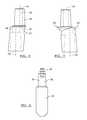
- FIG. 3Ais an anterior view of the tibial component of FIG. 1 ;
- FIG. 3Bis an anterior view of a tibial component according to additional features
- FIG. 3Cis a perspective view of a tibial component according to additional features
- FIG. 3Dis a perspective view of a tibial component according to additional features
- FIG. 4is a view of a first adapter body according to the present teachings.
- FIG. 5is a view of another adapter body according to additional features
- FIG. 6is a view of an exemplary stem and fastener insert
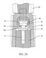
- FIG. 7Ais a cross-sectional view taken along a superior/inferior line through the adapter of FIG. 1 ;
- FIG. 7Bis a view of the knee joint prosthesis of FIG. 1 illustrating various offsets
- FIG. 7Cis an exploded view of a locking assembly shown in FIG. 7A ;
- FIG. 8is an anterior view of an exemplary femoral component according to the present teachings and shown with the adapter assembly of FIG. 1 ;
- FIG. 9is a perspective view of a tibial tray and bearing according to additional features.
- FIG. 10is a perspective view of the tibial tray of FIG. 9 ;
- FIG. 11is a perspective view of an inferior surface of the bearing of FIG. 9 ;
- FIG. 12is a perspective view of a superior surface of the bearing of FIG. 9 ;
- FIG. 13is a top view of the tibial tray and bearing of FIG. 9 ;
- FIG. 14is a cross-sectional view taken along the line 14 - 14 of FIG. 13 ;
- FIG. 15is a perspective view of a hinged knee joint prosthesis according to additional features.
- FIG. 16Ais a cross-sectional view taken along the line 16 - 16 of FIG. 15 and shown with the femoral component rotated;
- FIG. 16Bis a cross-sectional view of a hinged knee prosthesis according to additional features
- FIGS. 17-20show an exemplary sequence of assembling the knee joint prosthesis of FIG. 15 ;
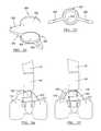
- FIG. 21is a perspective view of a first augment according to the present teachings.
- FIG. 22is a perspective view of a second augment according to the present teachings.
- FIG. 23Ais a plan view of the first and second augments of FIGS. 21 and 22 ;
- FIG. 23Bis side view of the first and second augments in an mated or interlocked position
- FIG. 24is a perspective view of a third augment according to the present teachings.
- FIG. 25is a top view of the third augment of FIG. 24 ;
- FIG. 26is an anterior view of the femoral component of FIG. 8 shown with the first augment assembled on a superiorly extending portion;
- FIG. 27is an anterior view of the femoral component of FIG. 8 shown with the first and second augments assembled on a superiorly extending portion;
- FIG. 28is a superior view of the femoral component of FIG. 27 and shown with the augment of FIG. 24 secured to an inferiorly extending portion;
- FIG. 29is an anterior view of the tibial component of FIG. 1 shown with the first and second augments assembled on an inferiorly extending portion and without the adapter assembly;
- FIG. 30is an anterior view of the tibial component of FIG. 1 shown with the third augment assembled on the inferiorly extending portion;
- FIG. 31is an exploded view of a modular tibial component according to additional features
- FIG. 32is a perspective view of an augment according to additional features
- FIG. 33is a perspective view of another augment according to the present teachings.
- FIG. 34is an exploded perspective view of an adapter assembly according to additional features and shown with an exemplary tibial component and stem;
- FIG. 35is an anterior view of the prosthesis illustrated in FIG. 34 ;
- FIG. 36Ais a detail exploded view of the tibial tray and adapter illustrated in FIG. 34 ;
- FIG. 36Bis a partial sectional view taken along line 36 B- 36 B of FIG. 36A ;
- FIG. 36Cis a detail exploded view of an adapter assembly cooperating with a tibial component according to additional features
- FIG. 36Dis a partial sectional view taken along line 36 D- 36 D of FIG. 36C ;
- FIG. 37is a sectional view of an exemplary adapter having a first offset
- FIG. 38is a sectional view of another exemplary adapter having a second offset
- FIG. 39Ais an exploded view of a fastener member and insert of the adapter assembly
- FIG. 39Bis a partial exploded view of an adapter assembly
- FIG. 40Ais an assembled view of a tibial component, adapter assembly and stem according to one example of the present teachings
- FIG. 40Bis a sectional view taken along line 40 B- 40 B of FIG. 40A ;
- FIG. 41Ais an assembled view of an exemplary femoral component, adapter assembly and stem according to one example of the present teachings
- FIG. 41Bis an assembled posterior perspective view of a pair of interlocking augments, adapter assembly and femoral component according to one example of the present teachings;
- FIGS. 42-45are perspective views of various tibial components and bearings used in cooperation with a bone conserving hinged knee;
- FIG. 46is a superior view of an assembled hinged knee
- FIG. 47is a sectional view taken along line 47 - 47 of FIG. 46 ;
- FIGS. 48A and 48Bare exploded perspective views of a hinged knee prosthesis according to one example of the present teachings.
- FIG. 49is a sectional view of the hinged knee prosthesis of FIGS. 48A and 48B shown assembled
- FIGS. 50-54are perspective views of various augments according to the present teachings.
- FIGS. 55A and 55Billustrates a kit of implants according to the present teachings
- FIGS. 56-60illustrate various augments shown during stages of assembly
- FIGS. 61-80Billustrate various instruments used for preparing a femur and tibia for receipt of the implants disclosed herein;
- FIG. 81-104illustrate exemplary sequences of using the instruments of FIGS. 61-80B ;
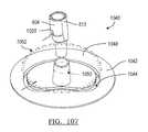
- FIGS. 105-107illustrate various apparatus for aligning an offset adapter at a desired orientation prior to joining with a desired femoral or tibial component
- FIGS. 108-120illustrate various instruments and a related sequence for preparing a tibia for receipt of a tibial prosthesis
- FIGS. 121-140illustrate various instruments and a related sequence for preparing a femur for receipt of a femoral prosthesis
- FIGS. 141 and 142illustrate various instruments and a related sequence for preparing a femur during a primary knee procedure.
- the instant disclosureprovides a knee joint prosthesis system having various knee joint prostheses that may be adapted for use in a revision knee procedure.
- Various tibial and femoral componentsare described that may be used alone or as part of a cruciate retaining (CR) knee revision, posterior stabilized (PS) knee revision, fully constrained knee revision and hinged knee revision.
- the instant disclosurefurther provides various modular adapters, stems and augments that may be used in any combination with any of the tibial and femoral components disclosed herein.
- all of the components disclosed that are above and below the joint linecan be inter-changeably used with any of the knee prostheses disclosed herein and on the tibial or femoral side.
- selection of any of the knee prostheses and related components from the knee joint prosthesis systemmay be selected intra-operatively by the surgeon performing the procedure.
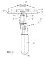
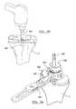
- a knee joint prosthesis constructed in accordance with the present teachingsis illustrated and generally identified at reference number 10 .
- the knee joint prosthesis 10is generally shown to include a tibial component 12 that supports a bearing 14 which engages an articulation surface of a femoral component (not shown).
- a femoral component(not shown)
- the tibial tray 12 and bearing 14can be adapted for use with any suitable femoral component.
- a first cruciate retaining (CR) bearing 14is illustrated that is designed to articulate with a CR femoral component.
- a fixed PS bearingmay be employed that is designed to articulate with a PS femoral component.
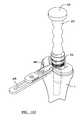
- the tibial component 12 illustrated in FIG. 1will be understood to be modular in construction and generally include a stem 20 , a tray 22 , and a first adapter assembly 24 .
- the adapter assembly 24can connect the tray 22 and the stem 20 so as to provide an offset to the stem 20 in the transverse or coronal plane or in any other plane.
- a central axis 25 of the stem 20can be offset from a central axis 27 of an inferiorly extending portion 28 of the tray 22 .
- the first adapter assembly 24can provide a first offset of approximately 5 mm.
- the offsetcan range from 0 mm to approximately 5 mm or more and can be in any rotational direction relative to the central axis 27 .
- a stem 20can be attached directly to the tray 22 ( FIG. 29 ).
- the offset axis 25can be rotated 360 degrees relative to the central axis 27 to provide the surgeon with various intra-operative options to select depending on the patient's needs.
- the adapter assembly 24 or stem 20can be rotational keyed to provide only a limited range of adjustment, such as providing only a single offset or two offset positions.
- the inferiorly extending portion 28 of the tibial tray 22can define a female tapered receiving portion 30 .
- the female tapered receiving portion 30can taper slightly as it extends into the inferiorly extending portion 28 .
- a central aperture 32can be formed through the tray 22 and the inferiorly extending portion 28 into the female tapered receiving portion 30 .
- the inferiorly extending portion 28may also define an exterior tapered augment receiving surface 34 .
- a retaining rail 36( FIG. 2 ) can extend superiorly from a posterior edge of the tray 22 .
- the tibial tray 22can further include a pair of posts 38 integrally formed on a superior surface at an anterior edge thereof. The posts 38 and rail 36 can cooperate to retain the modular bearing 14 in a fixed position on the tray 22 .
- An alternate tibial tray 22 ′is shown in FIG. 3B .
- the modular bearing 14can be formed of ultra-high molecular weight polyethylene (UHMWPE) with anterior and posterior recesses (not specifically shown) to receive the posts 38 and rail 36 , respectively, and with a uniformly flat inferior surface on its intercondylar and medial/lateral portions for direct contact with the superior surface of the tray 22 .
- UHMWPEultra-high molecular weight polyethylene
- the modular bearing 14can be designed to be locked in position with a transverse slide-in locking bar or clip 40 wedged between the posts 38 and the bearing 14 in opposed grooves provided therein for that purpose.
- a more detailed discussion of how the locking bar cooperates with the posts and bearingmay be found in commonly owned U.S. Pat. No. 5,330,534 entitled “Knee Joint Prosthesis With Interchangeable Components”, which is hereby incorporated by reference.
- Modular tibial trays and bearings as generally described aboveare commercially available from Biomet Inc., the assignee of the present disclosure, as components of the Vanguard® Complete Knee System, which includes various sizes and configurations of trays, bearings and other knee components for different patient requirements.
- the articulating surfaces of the modular bearing 14can be substantially the same as provided by the Vanguard® Complete Knee System.
- the adapter assembly 24can generally include an adapter body 44 and a locking member or element 46 ( FIG. 2 ).
- the adapter body 44 of the adapter assembly 24can define a male tapered insertion portion 48 having a passage 50 formed therethrough.
- a female tapered receiving portion 52can be formed in an offset body portion 53 of the adapter body 44 for receiving a male tapered insertion portion 58 of the stem 20 .
- the female tapered receiving portion 52can be generally cylindrical.
- a skirt 54can be defined at a transition between the male tapered insertion portion 48 and the offset body portion 53 .
- the male tapered insertion portion 48 of the adapter body 44defines a first axis A 1 and the female tapered receiving portion 52 defines a second axis A 2 .
- the first axis A 1 and the second axis A 2are parallel to one another and spaced apart to provide the desired offset.
- multiple adaptors each having a different offsetcan be provided to provide the surgeon with intra-operative selection depending on the patient's needs.
- the adapter body 44provides a 5 mm offset
- the first and second central axes A 1 and A 2are spaced apart 5 mm.
- the adapter body 44 ′can define a skirt 54 ′ having an alternate configuration. Other geometries are contemplated for the skirt 54 , 54 ′.
- the male tapered insertion portion 48can taper slightly as it extends away from the adapter body 44 .
- the female tapered receiving portion 52similarly tapers slightly as it extends into the adapter body 44 from an end of the adapter body 44 .
- various male tapered insertion portions(such as portion 48 ) can be inserted in various female tapered receiving portions (such as portion 52 ) to form a locking taper or Morse taper.
- the adapter body 44is illustrated to further define a laterally extending channel 60 which intersects both the aperture 50 and the female tapered receiving portion 52 .
- the locking element 46can extend into the laterally extending channel 60 where it ultimately couples the tray 22 to the stem 20 .
- the stem 20can include an upper portion 64 that cooperatively engages with the locking element 46 .
- the upper portion 64 of the stem 20can include a fastener insert 66 .
- the fastener insert 66 of the stem 20may be integrally formed to cooperate with the locking element 46 .
- the fastener insert 66can include a distal portion 70 which can be externally threaded for engaging an internally threaded aperture 72 of the male tapered insertion portion 58 of the stem 20 .
- the fastener insert 66can further include a central portion 74 having a hexagonal or other suitable cross-section which can be engaged by a tool (not shown) for rotating the fastener insert 66 into the stem 20 .
- the fastener insert 66can include a proximal end 78 including an enlarged diameter head 80 .
- the locking element 46can be sized and configured to be inserted through an opening 81 in the sidewall of the adapter body 44 and into the channel 60 for coupling of the stem 20 and the tray 22 .
- the locking element 46can include an upper surface 84 (see FIG. 2 ) having an internally threaded aperture 86 .
- the internally threaded aperture 86can threadably receive a fastener 90 which can extend through the central aperture 32 provided in the tray 22 .
- the fastener 90can align with the central longitudinal axis 27 of the inferior portion 28 of the tray 22 .
- the locking element 46can additionally include an open end 94 and a bottom surface having a slot 96 .
- the slot 96can intersect the open end 94 .
- the open end 94can receive the head 80 of the stem insert 66 as the locking element 46 is inserted through the opening 60 .
- the slot 96can accommodate a reduced diameter, central portion 100 of the fastener insert 66 .
- the head 80 of the fastener insert 66can have a diameter greater than a width of the slot 94 for coupling of the fastener insert 66 with the locking element 46 .
- the locking element 46can further include a closed end 104 .
- the closed end 104can be convexly curved. When the locking element 46 is completely inserted into the channel 60 , the closed end 104 can be flush with the sidewall of the adapter body 44 .
- the fastener insert 66can be screwed into the stem 20 .
- the adapter body 44can be placed over the male insertion portion 64 of the stem 20 such that the male insertion portion 64 is received in a press fit within the female tapered receiving portion 52 of the adapter body 44 and the upper end 78 of the fastener insert 66 extends into the laterally extending channel 60 .
- the male taper extension 48 of the adapter 44can now be press fit onto the female tapered receiving portion 30 of the tray 12 with the adapter body 44 oriented to provide the offset in the desired direction.
- the adapter body 44may be rotated about the axis A 1 prior to fastening to orient the stem 20 at the desired offset for a particular patient.
- the stem 20may extend at a plurality of positions around a radius defined by the axes A 1 and A 2 .
- the stem 20may be keyed with the adapted body thus, precluding rotation.
- a set of stemsmay be provided having various lengths suitable for a range of patients.
- a set of adapter bodiesmay be provided for providing various offsets.
- the locking element 46can be inserted into the laterally extending channel 60 through the opening 81 . Upon complete insertion, the locking element 46 can engage the fastener insert 66 .
- the tray 22can be secured to the adapter body 44 by the threaded fastener 90 which extends through the central aperture 32 of the tray 22 and threadably engages the internally threaded aperture 86 of the locking element 46 .
- the tibial traydefines an inferiorly extending male portion whereas in the instant application, the tibial tray 22 defines the inferiorly extending the female receiving portion 30 .
- the adapter body 44may alternatively define an axis A 2 that defines an angle with respect to the axis A 1 .
- the male insertion portion 58may be inserted directly into the female receiving portion 30 of the tray 22 .
- another threaded fastener 90 ′may be used that has a shorter shaft for spanning an appropriate distance to mate directly with the threaded aperture 72 of the stem 20 .
- FIGS. 3A-3Dother tibial trays 22 A, 22 B, 22 C and 22 D, are shown for accommodating various combinations of fasteners 90 , 90 ′, adapters 44 , 44 ′ and stems 20 .
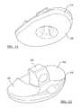
- the knee joint prosthesis 110includes a femoral component 112 .
- the femoral component 112may be used as part of a posterior stabilized (PS) knee joint prosthesis.
- PS knee joint prosthesiscan provide adequate stability in case of moderate deterioration or instability of a knee. This most typically occurs when the anterior and posterior cruciate ligaments are sacrificed or dysfunctional and the medial and lateral collateral ligaments remain functionally intact.
- the femoral component 112can include a first condylar portion 114 and a second condylar portion 116 that provide a first femoral bearing surface 118 and a second femoral bearing surface 120 , respectively.
- the first and second condylar portions 114 and 116 of the femoral component 112can be interconnected by an inner condylar portion 122 that defines an intercondylar recess 124 .
- a superiorly extending portion 130may be formed on the femoral component 112 .
- the superiorly extending portion 130can include a generally tapered outer body to receive the augments described herein and define a female tapered receiving portion 132 .
- the female tapered receiving portion 132 of the femoral component 112may be configured to accept one of the adapter bodies 44 , 44 ′ described above.
- the male tapered insertion portion 48 of the adapter body 44can be adapted to be inserted and press-fit into the female tapered receiving portion 132 of the femoral component 112 .
- the first axis A 1 and the second axis A 2are parallel to one another and spaced apart.
- the exemplary adapter assembly 24has been described as having a 5 mm offset however, other adapter bodies may be provided having various offsets.
- a locking element 46 and stem 20may be used according to the description above.
- the knee joint prosthesis 210is generally shown to include a tibial component 212 that supports a rotating constrained bearing 214 .
- the tibial component 212can generally include a substantially planar platform-like tibial tray 216 ( FIG. 10 ) and an inferiorly extending portion 218 .
- the inferiorly extending portion 218can define a tapered female receiving portion 220 and an outer tapered body for receiving augments disclosed herein.
- the tibial tray 216can further include a superiorly extending post 224 .
- a transition between the tibial tray 216 and the superiorly extending post 224can be defined by a varying radius R, or more specifically transition between a radius R 1 having a radius of approximately 0.50 inches, and a radius R 3 having a radius of approximately 1.50 inches.
- An intermediate radius R 2can have a radius of approximately 0.38 inches. It is appreciated that the radius R may define other dimensions.
- the transition of the varying radius Rcan minimize stresses experienced on the superiorly extending post 224 .
- An axis A 3 ( FIG. 14 ) defined through the post 224can be laterally offset in the posterior direction relative to an axis A 4 defined through the inferiorly extending portion 218 .
- a threaded aperture 228can be formed through the anterior portion of the tibial tray 216 . The threaded aperture 228 can extend generally perpendicular to the axis A 4 .
- the inferiorly extending portion 218can define a tapered augment receiving surface 230 .
- the tibial tray 216can be formed from cobalt-chromium-molybdenum or any other suitable biocompatible material.
- a top 232 ( FIG. 10 ) of the tibial tray 216can be highly polished to provide a substantially smooth tibial bearing surface 234 .
- the rotating bearing 214can have a substantially planar inferior bearing surface 238 ( FIG. 11 ) which can rotatably move relative to the highly polished tibial bearing surface 234 .
- the rotating bearing 212can further include a first superior articulating or bearing surface 240 and a second superior articulating or bearing surface 242 .
- the bearing surfaces 240 and 242can be formed anteriorly and laterally from a central superiorly extending portion 244 .
- the first bearing surface 240 and the second bearing surface 242can articulate with respective bearing surfaces of a first and second condyle of a constrained femoral component (not shown).
- the rotating bearing 212can be formed from a surgical grade, low friction, and low wearing plastic, such as UHMWPE or other suitable material.
- a posterior edge 246 of the tibial tray 216can define a surface that defines an angle 247 relative to a posterior edge 250 of the bearing 214 .
- the angle 247can be approximately 8 degrees. Other angles are contemplated.
- a stem 20is shown received directly into the female tapered receiving portion 220 of the tray 216 .
- an adapter body 44 or 44 ′may be used instead of inserting a stem 20 directly into the female tapered receiving portion 220 of the tray 216 .
- the stem 20can include a fastener insert 66 ′.
- the fastener insert 66 ′can include a distal portion 70 ′ which is externally threaded for engaging an internally threaded aperture 72 of the male tapered insertion portion 64 of the stem 20 .
- the fastener insert 66 ′can further include a central portion 74 ′ having a hexagonal or other suitable cross-section which can be engaged by a tool (not shown) for rotating the fastener insert 66 ′ into the stem 20 . Further, the fastener insert 66 ′ can include an upper end 78 ′ including a conical engaging head 80 ′.
- a set screw 252can be advanced through the threaded aperture 228 of the tibial tray 216 to engage the conical engaging head 80 ′. In this way, advancement of the set screw 252 can secure the fastener insert 66 ′, and therefore, the stem 20 in a secure position. It is appreciated that when utilizing the adapter body 44 , a fastener such as fastener insert 66 ′ but having a longer shank, may alternately be used for threadably securing to the locking element 46 .
- the knee joint prosthesis 310is generally shown to include a tibial component 312 that supports a bearing 314 which engages an articulation surface of a femoral component 316 .
- the tibial component 312can generally include a substantially planar platform-like tibial tray 318 and an inferiorly extending portion 320 .
- the inferiorly extending portion 320can define a tapered female receiving portion 322 .
- the tibial tray 318can further include a superiorly extending post 324 .
- a cap 326can be securably inserted into an elongate bore 328 defined at a terminal opening of the superiorly extending post 324 .
- a threaded aperture 330can be formed through the tibial tray 318 .
- the threaded aperture 330can extend generally perpendicular to an axis defined by the superiorly extending post 324 .
- the tibial tray 318can be formed from cobalt-chromium-molybdenum or any other suitable biocompatible material.
- a set screw(not shown) can be advanced through the threaded aperture 330 of the tibial tray 318 to engage a conical engaging head of a fastener insert (as described in detail above regarding FIG. 14 ). In this way, advancement of the set screw can secure the fastener insert, and therefore the adapter body 44 or the stem 20 in a secure position.
- the top of the tibial tray 318can be highly polished to provide a substantially smooth tibial bearing surface 331 .
- the rotating bearing 314can have a substantially planar inferior bearing surface 332 which can rotatably move relative to the highly polished tibial bearing surface 331 .
- the rotating bearing 314can further include a first superior articulating or bearing surface 336 and a second superior articulating or bearing surface 338 .
- the first bearing surface 336 and the second bearing surface 338can articulate with respective bearing surfaces of a first and second condyle 340 and 342 , respectively of the femoral component 316 .
- the bearing surfacesmay be similar to those provided in the Vanguard® Complete Knee System.
- the bearing 314can include a stabilizing post 350 which can project superiorly from the bearing surface.
- the stabilizing post 350can include a fin-like body 352 having a raised posterior portion 354 and a lower anterior portion 356 .
- the body 350can define a first and second laterally spaced-apart sides 360 and 362 ( FIG. 17 ).
- the first and second sides 360 and 362 of the stabilizing post 350can be positioned so as to extend into an intercondylar recess 366 ( FIG. 15 ) of the femoral component 316 .
- a stabilizing post aperture 370can be formed in a superior/inferior direction through the body 350 .
- a passage 372can be formed through the raised posterior portion 354 of the body 350 .
- the passage 372can extend generally through the first and second sides 360 and 362 of the stabilizing post 350 in a direction generally perpendicular to the stabilizing post aperture 370 .
- the rotating bearing 314can be formed from a surgical grade, low friction, and low wearing plastic, such as UHMWPE or other suitable material.
- FIG. 16BAn alternate stabilizing post 350 ′ is shown in FIG. 16B that accepts a cap or fastener 326 ′.
- the first and second condylar portions 340 and 342 of the femoral component 316can be interconnected by an inner condylar portion 380 that defines the intercondylar recess 366 .
- the intercondylar portion 380can include a first lateral sidewall 382 and a second lateral sidewall 384 ( FIG. 17 ) which can be planar and substantially parallel to each other.
- the first and second lateral sidewalls 382 and 384can further define hinge passages 388 formed respectively therethrough.
- Anterior portions of the first and second lateral sidewalls 382 and 384can be connected by an anterior surface 390 ( FIG. 15 ) of the intercondylar portion 380 .
- the anterior surface 390 of the intercondylar portion 380can angle anteriorly in an inferior direction at approximately 60 degrees with respect to a superior surface of the intercondylar portion 380 .
- a superiorly extending portion 392may be formed on the femoral component 316 and generally extend from a superior surface 394 ( FIG. 16A ).
- the superiorly extending portion 392can include a generally cylindrical body and define a female tapered receiving portion 394 .
- a hinge post 396can securably extend through the respective hinge passages 388 of the first and second lateral sidewalls 382 and 384 of the femoral component 316 and through the passage 372 in the bearing 314 .
- the lateral sidewalls 382 and 384 of the femoral component 316can be positioned proximate an inboard portion of the respective first and second condyles 340 and 342 . In this way, host bone need not be sacrificed in areas outboard to the lateral sidewalls 382 and 384 .
- the femoral component 316can rotate about the hinge pin 396 .
- FIG. 17illustrates an exploded view of the respective femoral component 310 , hinge pin 396 and bearing 314 .
- the femoral component 310is placed onto the bearing 314 such that the respective passages 372 and 388 are aligned.
- FIGS. 19-20show the hinge pin 296 inserted into the passages 372 and 388 .
- FIGS. 21-23Billustrate a first pair of augments 400 and 402 .
- the first augment 400can generally define a body 404 having first end 406 and a second end 408 .
- the body 404can further define a consistent radius portion 410 at the second end and 408 an outwardly tapered radially extending portion 412 near the first end 406 .
- the consistent radius portion 410can define a tapered receiving bore 416 formed therethrough.
- the receiving bore 416can taper from the first end 406 to the second end 408 .
- a first step 420may be formed in the body 404 between the consistent radius and the radially extending portions 410 and 412 , respectively.
- a collection of first augmentsmay be provided having various dimensions and configurations suitable for a particular patient.
- the second augment 402can generally define a body 424 having first end 426 and a second end 428 .
- the body 424can further define a consistent radius portion 430 at the first end 426 and an outwardly tapered radially extending portion 432 near the second end 428 .
- the consistent radius portion 430can define a tapered receiving bore 436 formed therethrough.
- the receiving bore 436can taper from the first end 426 to the second end 428 .
- a second step 440may be formed at the second end 428 between the consistent radius and the radially extending portions 430 and 432 , respectively.
- a collection of first augmentsmay be provided having various dimensions and configurations suitable for a particular patient.
- the first and second augments 400 and 402may be used singly or as a combination. As shown in FIG. 23B , the first and second augments 400 and 402 can interlock or mate at the first and second steps 420 and 440 when used concurrently with any of the tibial and femoral components described above.
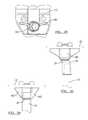
- the third augment 450can generally define a body 452 having a first end 454 and a second end 456 .
- the body 452can further define a pair of wing portions 460 extending radially therefrom to provide rotational stability to either the femoral component or the tibial component.
- the wing portions 460may be offset toward the first end 454 .
- the body 452can define a tapered receiving bore 464 formed therethrough. The receiving bore 464 can taper from the second end 456 to the first end 454 .
- the receiving bores 416 , 436 and 464 of each of the augments 400 , 402 and 450can be slidably press-fit onto any of the inferior extensions of the tibial trays described above. More specifically, the receiving bores can define a tapered interlock with the tapered augment receiving surfaces of the inferior extensions of the tibial trays. Likewise, any of the same augments can also be slidably press-fit onto any of the superior extensions of the femoral components described above. More specifically, the receiving bores can define a tapered interlock with the tapered augment receiving surfaces of the superior extensions of the femoral components. As such, the respective tapered surfaces can cooperate to form a Morse taper.
- a second augment 402is shown secured to the superior extension 130 of the femoral component 112 ( FIG. 26 ). If a surgeon desires to account for additional bone loss, the first augment 400 may also be advanced onto the superior extension 130 of the femoral component 112 ( FIGS. 27 and 29 ). As shown, the respective first and second steps 420 and 440 cooperate to mate or form an interlock.
- FIG. 29a first and second augment 400 and 402 are shown secured to the inferior extension 28 of the tibial tray 22 .
- the first and second augments 400 and 402may be used with or without the adapter. It is appreciated, that any of the augments may be used with or without the adapter assemblies described above.
- FIG. 30illustrates the third augment 450 secured to the inferior extension 28 of the tibial tray 22 .
- the tibial component 522can define one or more (such as a pair) of blind bores 524 and at least one opening 526 formed on an inferior surface.
- a recessed portion such as pocket 530may also be optionally formed on an inferior surface of the tibial component 522 .
- An augment 540can define one or more (such as a pair) of complementary locating pegs 542 and at least one complementary opening 544 .
- the augment 540can be adapted to secure onto the inferior surface of the tibial component 522 to compensate for bone loss.
- an augmentmay be provided on one of a lateral or medial portion, or both, of the tibial component 522 .
- the locating peg 542may nest within a blind bore 524 .
- a fastener(not shown) may be inserted through the respective openings 526 and 544 .
- Another augment 540 ′ having at least one peg 542 ′can be provided for the opposite of the medial and lateral sides of the inferior surface of the tibial component 522 .
- an augment 540 ′′ suitable for connecting to either of the medial and lateral sidesis provided.
- pegs(such as pegs 542 , FIG. 31 ) need not be provided.
- a plurality of augments 540can be provided having various thicknesses such that a surgeon can assemble a particular augment suitable for a given patient.
- a stem 20can be fixedly accepted into a female tapered extending portion 560 of the tray.
- FIG. 33illustrates another augment 590 that defines a tapered receiving bore 592 formed therethrough.
- the tapered receiving bore 592can be slidably press-fit onto any of the inferior extensions of the tibial trays and/or the superior extensions of the femoral components described above.
- a portion of the augment 590can optionally be formed of porous metal 594 .
- the porous metal 594can comprise porous titanium alloy for example.
- the augment 590can define an inner solid metal sleeve portion and an outer porous metal sleeve portion 594 .
- the respective femoral components, tibial components, bearings and/or augmentsmay be part of a kit wherein a surgeon may intra-operatively select a desired component or components needed for a particular patient.
- the modular tibial component 22(as described above with respect to FIGS. 1-3A ) is shown cooperating with an adapter assembly 600 according to additional features.
- the adapter assembly 600can cooperate with the stem 20 .
- the adapter assembly 600can connect the tray 22 and the stem 20 so as to provide an offset to the stem 20 in the transverse or coronal plane or in any other plane.
- the central axis 25 of the stem 20can be offset from the central axis 27 of the inferiorly extending portion 28 of the tray 22 .
- the adapter assembly 600can provide a first offset of approximately 5 mm. It is appreciated that the offset can range from 0 mm to approximately 5 mm or more and can be in any rotational direction relative to the central axis 27 . In other words, the offset axis 25 can be rotated 360 degrees relative to the central axis 27 to provide the surgeon with various intra-operative options to select depending on the patient's needs. Alternatively, the adapter assembly 600 or stem 20 can be rotational keyed to provide only a limited range of adjustment, such as providing only a single offset or two offset positions.
- the adapter assembly 600can generally include an adapter body 604 and a locking member or element 606 .
- the adapter body 604 of the adapter assembly 600can define a male tapered insertion portion 608 and a female tapered receiving portion 610 .
- the male tapered insertion portion 608can define a threaded bore 611 .
- the female tapered receiving portion 610can be formed in an offset body portion 612 of the adapter body 604 for receiving a male tapered insertion portion 58 of the stem 20 .
- the adapter body 604can define flats 614 on an outer surface for gripping and facilitating alignment as will be described.
- a skirt(not shown), similar to the skirt 54 formed on the adapter body 44 illustrated in FIG. 2 , can be defined at a transition between the male tapered insertion portion 608 and the offset body portion 612 .
- a non-skirted transitioncan alternatively be formed as shown herein.
- a bore 614can be defined from an outer surface of the adapter body 604 to the female tapered receiving portion 610 .
- the bore 614can define threads 616 that threadably receive the locking member 606 .
- the male tapered insertion portion 608 of the adapter body 604defines a first axis A 5 and the female tapered receiving portion 610 defines a second axis A 6 .
- the first axis A 5 and the second axis A 6are parallel to one another and spaced apart to provide the desired offset.
- multiple adaptors each having a different offsetcan be provided to provide the surgeon with intra-operative selection depending on the patient's needs.
- the adapter body 604provides a 5 mm offset
- the first and second central axes A 5 and A 6are spaced apart 5 mm.
- the adapter body 604can define axes having an alternate offset.
- an adapter body 604 ′( FIG. 38 ) includes a male tapered insertion portion 608 ′ that defines a first axis A 7 and the female tapered receiving portion 610 ′ that defines a second axis A 8 .
- the adapter body 604 ′can define an offset of 2.5 mm.
- the male tapered insertion portion 608can taper slightly as it extends away from the adapter body 604 .
- the female tapered receiving portion 610similarly tapers slightly as it extends into the adapter body 604 from an end of the adapter body 604 .
- various male tapered insertion portions(such as portion 608 ) can be inserted in various female tapered receiving portions (such as portion 610 ) to form a locking taper or Morse taper.
- the locking member 606can extend into the bore 614 where it ultimately engages a fastener insert 620 .
- the fastener insert 620can include a distal portion 622 which can be externally threaded for engaging the internally threaded aperture 72 of the male tapered insertion portion 58 of the stem 20 .
- the fastener insert 620can further include a central portion 624 and a proximal portion 626 .
- the proximal portion 626can define a conical engaging head 630 .
- a gripping detail 632(such as, but not limited to, a hex-bore for receiving an Allen wrench), can be formed in an upper surface of the proximal portion 626 .
- the fastener insert 620or more specifically the conical engaging head 630 can be formed of a first biocompatible material while the locking member 606 can be formed of a second biocompatible material.
- the second biocompatible materialcan be a higher durometer (harder) material than the first biocompatible material.
- the tibial tray 636can be part of a bone-conserving hinge knee prosthesis ( FIG. 48A ).
- the tibial tray 636can define a superiorly extending stub 637 and an inferiorly extending portion 638 that defines a female tapered receiving portion 640 .
- the inferiorly extending portion 638can define an exterior tapered augment receiving surface 642 .
- the tibial tray 636can define a threaded passage 646 formed through the tray portion of the tibial tray 636 .
- the treaded passage 646can be adapted to threadably accept the locking member 606 .
- the tibial tray 636can provide the threaded passage 646 for receiving the locking member 606 in the anterior/posterior direction.
- the fastener insert 620can be threaded into the threaded bore 611 .
- the fastener insert 620can be threaded until the central portion 624 engages a terminal surface 650 of the male tapered insertion portion 608 of the adapter body 604 .
- the stem 20can be coupled to the adapter body or the adapter body 604 can be coupled to the tibial tray 636 .
- the adapter body 604can be coupled to the tibial tray 636 , by inserting the male tapered insertion portion 608 of the adapter body 604 into the female tapered receiving portion 640 of the tibial tray 636 . The surgeon can then rotate the male tapered insertion portion 608 within the female tapered receiving portion 640 to attain the desired orientation.
- the instant disclosureprovides various tools for verifying a correct orientation of the adapter body 604 prior to securing the adapter body 604 in a fixed position relative to the tibial tray 636 .
- the locking member 606can be threaded from an unsecured position ( FIG. 36C ) into engagement with the conical engaging head 630 to a secured position ( FIG. 36D ).
- the locking member 606can be formed of a biocompatible material that is harder than the fastener insert 620 .
- a distal end 654 of the locking member 606can deform (e.g. create a depression at) an interface area of the conical engaging head 630 .
- the deformed areais identified at reference numeral 656 ( FIGS. 39A and 40B ).
- the locking function of the locking member 606can be improved by providing a greater resistance to separation.
- the resultant depressioncan inhibit sliding, rotation, or other relative movement between the locking member 606 and the fastener insert 620 .
- the stem 20can be coupled to the adapter body 604 by driving the locking member 606 (i.e. another identical locking member 606 ) into the fastener insert 620 (i.e. another identical fastener insert 620 ).
- the locking member 606i.e. another identical locking member 606
- the fastener insert 620i.e. another identical fastener insert 620
- the threads 616 defined by the bore 614can define a thread profile that is slightly different (i.e. pitch) than threads 662 defined by the locking member 606 .
- one of the threads 616 or 662can be deformed initially.
- Such a relationshipcan allow the locking member 606 to be retained within the bore 614 upon initial handling by a surgeon.
- the locking member 606can already by positioned within the bore such that the surgeon would not need to locate the distal tip 654 of the locking member 606 into the bore 616 (i.e. mate two separate components). It is appreciated that such thread configuration would not preclude rotation of the locking member 606 within the bore 616 during fastening.
- the adapter assembly 600 including the adapter body 604 and the locking member 606are shown assembled with a femoral component 112 ′.
- the femoral component 112 ′is substantially similar to the femoral component 112 ( FIG. 8 ), but can define a threaded bore 668 formed in a femoral box 670 .
- the threaded bore 668can provide a similar function to the threads 616 of the bore 614 of the adapter body 604 .
- a locking member 606can be driven to engage a conical engaging head 630 of fastener insert 620 .
- a skirt 54 ′′is shown on the adapter body 604 .
- the skirt 54 ′′generally defines a flared contour portion that can provide a generally smooth geometrical transition onto the outwardly tapered radially extending portion 432 (see also FIG. 21 ) of the augment 402 .
- the geometrical transition between the skirt 54 ′′ and the augment 402can reduce otherwise sharp transitions between implanted components to provide a favorable nesting configuration with surrounding bone in an implanted position.
- the male tapered insertion portion 608 of the adapter 604can define an attachment axis 671 .
- the outwardly tapered radially extending portion 432 of the body 424can define a plane 673 .
- the flared contour portion of the skirt 54 ′′can taper generally along the plane 673 in an implanted position. The skirt 54 ′′ can therefore cooperate with the augment 402 to effectively fill bone voids.
- an adapter assembly 600can be used on either side of the joint line (e.g. with a tibial component, such as described in relation to FIG. 35 , and also a femoral component, such as described in relation to FIG. 41 ).
- the locking member 606 and fastener insert 620 combinationcan be used in several distinct areas as described above.
- the augments such as disclosed in FIGS. 21-25can be used in cooperation with either a superiorly extending portion (such as portion 130 , FIG. 8 ) of a femoral component or an inferiorly extending portion (such as portion 638 , FIG. 36C ) of a tibial component.
- the tibial tray 636can be used as part of a bone-conserving hinge knee prosthesis.
- the tibial tray 636can cooperate with a bearing 672 .
- a keel 680can define a first bore 682 for receiving the superiorly extending stub 637 , and a second bore 684 for receiving an axle 686 .
- a pair of hubs 688can engage opposite ends of the axle 686 .
- a biasing member 687can bias against an outer surface on the keel 680 to bias the axle 686 outward.
- the keel 680can be intraoperatively coupled to the femoral component 692 by depressing the axle 686 in a direction inwardly and locating the keel 680 generally into the femoral box 696 of the femoral component 692 until the axle 686 aligns with passages 695 and 697 formed in the femoral box.
- the hubs 688can nest in the passages 695 and 697 on opposite ends of the axle 686 .
- the axle 686can bias outwardly encouraging the hubs 688 to seat into the passages 695 and 697 .
- the hubs 688can provide a rotational surface for supporting the axle 686 .
- the hubs 688can be formed of any suitable bearing material such as PEEK, polyethylene, carbon reinforced PEEK.
- a pin 700can then be inserted into the keel 680 to inhibit inward compression of the axle 686 .
- a shoe 690can be disposed intermediate of the keel 680 and a femoral component 692 .
- the femoral component 692can define a threaded bore 694 through the box 696 .
- a superiorly extending portion 698can receive a male tapered insertion portion 608 of the adapter body 604 .
- the locking member 606can be used as described above to engage a fastener insert 620 (not specifically shown) extending proud from the male insertion portion 608 .
- a fastenercan extend superiorly though the femoral component 692 to securably mate with the adapter body 604 (such as shown in FIG. 8 ).
- a horseshoe clip 702can securably nest in an annular pocket 704 defined on the stub 637 .
- An augment 710can define a substantially symmetric profile for securing to either a medial or lateral inferior side of a tibial tray (i.e. such as a tibial tray 22 D, FIG. 3D ).
- Passages 712can be formed through the augment 710 for receiving a fastener (not shown) in an assembled position.
- Augments 716 and 718can define passages 720 and 722 , respectively for receiving a superiorly extending portion 724 of a femoral component 730 (see FIG. 58 ).
- the augments 716 and 718can define a profile unique for cooperating with a medial or lateral side of a femoral box 732 .
- the augment 716can be implanted to occupy an area of bone loss on a medial side of the femoral component 730 .
- the augment 718can be implanted to occupy an area of bone loss on a lateral side of the femoral component.
- Augments 734 and 736can define passages 738 and 740 respectively ( FIG. 59 ).
- the augments 734 and 736can be used individually or in combination.
- the respective passages 720 , 722 , 738 and 740 and the superiorly extending portion 724 of the femoral component 730can define conical engaging surfaces that are adapted to provide a friction fit formed by a Morse-type taper.
- the augments 734 and 736can define a profile different than the augments 716 and 718 .
- the augment 744can define a passage 746 .
- the augment 744can be symmetric for coupling to either a medial or lateral surface of the femoral component 730 .
- Threaded blind bores 750 and 752can be defined on the femoral component 730 for accepting a fastener (not shown) for securing an augment 744 .
- Another augment 744 ′can be provided (that can have a mirror image profile relative to the augment 744 ) for compatibility with only the medial (or lateral) side of the femoral component.
- a saddlebag augment 754 having a central passage 756is shown.
- the central passage 756can receive the superiorly extending portion 724 of a femoral component 730 .
- the central passage 756 and the superiorly extending portion 724can define conical engaging surfaces that are adapted to provide a friction fit formed by a Morse-type taper.
- FIG. 60illustrates a femoral component 730 having the winged augment 450 ( FIG. 24 ) secured to the superiorly extending portion 724 .
- each of the augments disclosed hereincan be formed of biocompatible material such as solid metal, porous metal or a combination of solid metal and porous metal.
- the solid metal or porous metalcan comprise stainless steel, titanium, titanium alloys, cobalt-chromium alloys and other materials that are suited for use in a biocompatible environment.
- porous metalcan provide a suitable surface area for encouraging ingrowth of natural bone and/or soft tissue.
- Various compositions and methods of making such porous metalmay be found in co-pending applications, U.S. Ser. Nos. 11/111,123, filed Apr. 21, 2005; Ser. No. 11/294,692, filed Dec. 5, 2005; Ser. No. 11/357,868, filed Feb.
- FIG. 55Aillustrates a kit of components 760 .
- the kit of componentscan be used interchangeably as discussed herein.
- the stemscan define various lengths and diameters.
- the adapterscan define various offsets.
- FIG. 55Billustrates such interchangeability. For instance, a surgeon can intraoperatively select a desired femoral component A, a tibial component B, a bearing C, and augment D and an offset adapter E. While not shown, a suitable stem (such as stem 20 ) can also be coupled to the offset adapter E as described herein.
- the tapered female receiving portionshave been described as receiving the tapered male insertion portions by way of press-fit.
- the female receiving portions and male insertion portionsall define conical engaging surfaces adapted to provide a friction fit formed by a Morse-type taper.
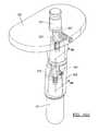
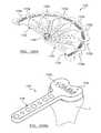
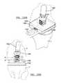
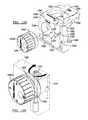
- a distal resection cutting guide 800( FIG. 61 ) can include a distal resection block 802 and a removable bracket portion 804 having a pair of dials 806 , 808 for selecting a desired orientation (i.e. valgus angle etc.).
- the distal resection block 802can define resection slots of +0, +4, +8, and +12 mm, collectively referred to at reference 810 for distal resection.
- the +0 slotcan resect from the most prominent condyle as a clean-up cut. Other configurations are contemplated. If there is a defect, the +4, +8, or the +12 mm slot can be used for later use with a respective 4, 8 or 12 mm distal augmentation block.
- a distal cutting block 812( FIGS. 62A-62D ) can define lateral anterior and posterior slots 822 and 824 and anterior and posterior chamfer slots 826 and 828 .
- the distal cutting block 812can be referred to herein as a “cutting” block.
- First and second partially overlapping bores 830 and 832can be defined through a central portion 834 of the distal cutting block 812 .
- one of the bores 830 or 832can be aligned for use with a right femur while the other can be aligned for use with a left femur.
- a mark 836 , 837can be defined adjacent to the respective bores 830 , 832 .
- a rotatable offset bushing 838( FIG.
- the offset bushing 838can define an offset passage 840 and indicia 842 .
- the offset passage 840can be laterally offset relative to a longitudinal axis of the offset bushing 838 .
- a plurality of offset bushings(such as offset bushing 838 ′, FIG. 67 ) can be provided that provide various offsets suitable for a range of patient needs. In the examples shown, the offset bushing 838 can provide a 5 mm offset and the offset bushing 838 ′ can provide a 2.5 mm offset.
- a bushing 838 ′′( FIG. 68 ) can have a zero offset. Augment trials 844 ( FIG.
- the augment trials 844can define a series of detents 870 for selectively capturing around a fastener 872 ( FIGS. 64A and 64B ).
- the series of detents 870can locate the augment trials 844 at a desired location.
- a femoral offset template 876( FIGS. 70A and 70B ) can define a plurality of apertures 880 for locating the fastener 872 and augment trial 844 at various locations.
- an offset templatecan be unique to a left femur (e.g. FIGS. 70A and 70B ) or right femur (e.g. template 876 ′, FIG. 71 ).
- a universal revision alignment member 882( FIG. 69 ) can define a pocket 884 for receiving the bushing 838 (or 838 ′).
- a mark 886can be defined on the pocket 884 for aligning with the indicia 842 .
- a tibial template 890( FIG. 78 ) can be provided for use during tibial preparation.
- tibial template 890can cooperate with an augment cut block 892 .
- An implant boss reamer bushing 896( FIG. 76 ) can be provided for receipt into the pocket 884 of the alignment member 882 .
- the universal revision alignment member 882 , offset bushing 838 , and reamer bushing 896can all be used with either the femoral offset template 876 or the tibial template 890 .
- a tibial bushing stop 900( FIG. 77 ) can be provided for locating between the reamer bushing 896 and a collar 902 of a reamer bit 904 ( FIG. 65 ).
- the tibial bushing stop 900can be used to limit a reaming depth in the tibial canal when reaming a tibial bore.
- the depth of a reamed tibial canalcan be shallower than a depth of a reamed femoral canal.
- An offset adapter rasp bushing 910( FIG. 74 ) can define a half-moon shaped passage 912 .
- the half-moon shaped passage 912can define a flat 914 .
- the offset adapter rasp bushing 910can cooperate with the pocket 884 of the universal revision alignment member 882 (during either femoral or tibial offset bore preparation).
- the offset adapter rasp bushing 910can define indicia 918 for aligning with the mark 886 on the pocket 884 .
- the offset adapter rasp bushing 910can be rotated to dial in a desired orientation that corresponds to the desired offset orientation of the adapter body 604 ( FIG. 34 ).
- Another offset adapter rasp bushing 710 ′( FIG. 75 ) can define another offset.
- a rasp 922( FIGS. 72A and 72B ) can define an impacting portion 924 on a distal end 926 , and a handle 930 on a proximal end 932 .
- a planar surface 934can be defined along the impacting portion 924 .
- the planar surface 934can cooperate with the flat 914 of the offset adapter rasp bushing 910 to locate the rasp 922 in a desired orientation.
- a posterior stabilized box guide 940 or 942( FIGS. 80A and 80B ) or can be provided for preparation of a posterior stabilized femur. Slots 944 , 946 can be defined through the posterior stabilized box guide 940 and 942 , respectively for guiding a cutting member at a given location.
- the posterior stabilized box guide 940can define passages 950 for accepting the augment trials 844 in a similar manner described above.
- the distal femur Fcan be exposed and a femoral (intramedullary) canal 954 can be reamed until cortical contact is achieved using a reamer 956 ( FIG. 81 ).
- the distal cutting guide 810can be secured to the distal femur F and aligned to a desired orientation using the dials 806 , 808 .
- the bracket portion 804can then be removed from the block 802 , leaving the distal resection block 802 on the anterior bone.
- the reamer 956may be left in the bone F. While avoiding the reamer 956 , distal resection through the selected slots 810 can be performed using a sawblade 960 .
- the distal cutting guide 810can be removed while leaving in the reamer 956 ( FIG. 83B ).
- an augment trial 844(or trials) can then be snapped onto the back side of the cutting block 812 ( FIG. 83C ).
- the offset bushing 838can be inserted into the appropriate overlapping bore 830 of the cutting block 812 .
- the cutting block 812is then inserted over the reamer shaft 956 such that the reamer shaft 956 locates through the offset bore 840 of the offset bushing 838 ( FIG. 84 ).
- the offset bushing 838is then rotated (thereby translating the cutting block 812 around the distal femur F) until the desired position of the cutting block 812 is attained.
- a bolt (not shown) extending through an anterior passage 960 in the cutting block 812can then be tightened to preclude further movement of the offset bushing 838 .
- the cutting block 812can then be secured to the distal femur F such as by driving nails 962 through holes 964 provided on the cutting block 812 .
- the alignment numberi.e. the indicia 842 corresponding to the mark 836 .
- the offset bushing 838can then be removed.
- the anterior and posterior bonecan be resected followed by the anterior and posterior chamfer cuts using a sawblade 966 ( FIG. 85 ).
- the cutting block 812can then be removed from the distal femur F while leaving the reamer 956 in place ( FIG. 86 ).
- Augment trials 844can then be coupled to the back side of the femoral offset template 876 using a desired hole 880 .
- the universal revision alignment member 882can be coupled to top side of the femoral template 876 ( FIG. 88 ).
- the offset bushing 838can be inserted into the pocket 884 .
- the reamer bit 904can be inserted through the passage 804 in the offset bushing 838 and the assembly can be dropped onto the distal femur F.
- the offset bushing 838can then be rotated to the alignment number 842 noted from above.
- the femoral offset template 876can be secured to the distal femur F.
- the offset bushing 838can then be removed from the pocket 884 .
- the implant boss reamer bushing 896can then be inserted into the pocket 884 ( FIG. 89 ).
- the reamer bit 904can be directed through the implant boss reamer bushing 896 to ream an implant boss 969 ( FIGS. 90 and 92 ).
- the implant boss reamer bushing 896can then be removed from the pocket 884 and swapped out for the offset adapter rasp bushing 910 .
- the rotational orientationcan be verified (i.e. to match the alignment number noted above).
- the rasp 922can be driven (i.e. repeatedly) through the half-moon shaped passage 912 of the offset adapter rasp bushing 910 (to create an offset bore portion 970 ). Again, the offset adapter rasp bushing 910 aligns the rasp 922 for preparing an offset passage within the femoral bore.
- the offset passagecan substantially correspond to the profile (and rotational orientation) of the offset adapter (see superimposed components, FIG. 93 ).
- the posterior stabilized box guide 740( FIGS. 94A and 94B ) can be used to create a PS box at the outset of femoral preparation as is known in the art.
- a tibia Tfor accepting a tibial component having an offset adapter
- the proximal tibia Tcan be exposed and resected.
- a tibial (intramedullary) canal 980can be reamed using a reamer 956 .
- the universal revision alignment member 882can be coupled to top side of the tibial template 890 .
- the offset bushing 838can be inserted into the pocket 884 of the universal revision alignment member 882 .
- the reamer shaft 956can be inserted through the passage 840 in the offset bushing 838 and the assembly can be dropped onto the proximal tibia T ( FIG. 96 ).
- the offset bushing 838can then be rotated causing the tibial template 890 to translate around the proximal tibia T until optimal tibial coverage is attained.
- the tibial template 890is then secured to the proximal tibia T.
- the alignment numberis noted.
- the tibial template 890 with augment cut block 892can be secured to the proximal tibia T.
- the proximal tibia Tcan then be cut such as to form a notch 982 ( FIG. 98B ) on the proximal tibia T.
- a trial augment 984can then be inserted onto the bottom surface of the tibial template 890 .
- the implant boss reamer bushing 896can then be inserted into the pocket 884 .
- the tibial bushing stop 900is then located between the collar 902 of the reamer bit 904 and the implant boss reamer bushing 896 (to limit the depth of cut).
- the reamer bit 904can be directed through the implant boss reamer bushing 896 to ream the implant boss ( FIG. 101 ).
- the implant boss reamer bushing 896 and tibial bushing step 900can then be removed from the pocket 884 and swapped out for the offset adapter rasp bushing 910 .
- the rotational orientationcan be verified (i.e. to match the alignment number noted above).
- the rasp 922can be driven (i.e.
- the offset adapter rasp bushing 910aligns the rasp 922 for preparing an offset passage within the tibial bore ( FIG. 104 ).
- the offset passagecan substantially correspond to the profile (and rotational orientation) of the offset adapter body 604 .
- an apparatus 1000 for aligning an offset adapter body 604 rotationally with a receiving portion of an implanti.e. female tapered receiving portion of a tibial component or a femoral component.
- the apparatus 1000is shown securing a tibial component 22 , while it is appreciated that the apparatus can also secure a femoral component (such as any femoral component disclosed herein).
- the apparatus 1000can generally define an outer frame 1002 defining a scale of indicia 1004 thereon.
- a plurality of arms 1006can be movably secured to the outer frame 1002 .
- a corresponding plurality of hands 1010can be defined on distal ends of the arms 1006 .
- the arms 1006 and hands 1010can be locked in position.
- the implanti.e. tray 22
- the known positioncan be such that the tibial tray 22 is positioned with the anterior portion aligned with the indicia 1004 (i.e. at indicia numeral “ 60 ”).
- a pointer 1016can be mounted for rotation around the outer frame 1002 .
- the indicia 1004can be at a known location relative to the indicia 842 on the offset bushing 838 .
- the pointercan then be rotated around the dial 1004 to correspond to the noted number dialed in with the offset bushing 838 .
- a mark 1020can be aligned with the pointer 1016 and dropped into the female tapered receiving portion 30 of the tibial tray 22 .
- the Morse-type taper interfaceas described in detail, can secure the adapter body 604 relative to the tray 22 until supplemental mechanical securement (such as the fastener 90 ′, FIG. 34 , or locking element 606 , FIG. 36D ).
- FIG. 106Another apparatus 1026 for aligning an offset adapter body 604 rotationally with a receiving portion of an implant (i.e. female tapered receiving portion of a tibial component or a femoral component) is shown in FIG. 106 .
- the apparatus 1026can include the dial 1002 , arms 1006 and hands 1010 as described above (or any suitable securing device).
- a dial 1030can be rotatably suspended above the tibial tray 22 . In one example, the dial 1030 can rotate within a halo 1032 extending above the dial 1002 .
- the dial 1030can define a mark 1036 and a keyhole 1040 .
- the keyholecan correspond to a footprint that slidably accepts the flats 613 of the adapter body 604 so that the adapter body is rotatably fixed in the keyhole 1040 .
- the dial 1030can be rotated until the mark 1036 aligns with the noted number dialed in with the offset bushing 838 .
- the adaptercan then be dropped through the keyhole 1040 and into the female tapered receiving portion 30 of the tibial tray 22 .
- the Morse-type taper interfaceas described in detail, can secure the adapter body 604 relative to the tray 22 until supplemental mechanical securement (such as the fastener 90 ′, FIG. 34 , or locking element 606 , FIG. 36D ).
- FIG. 107Another apparatus 1040 for aligning an offset adapter body 604 rotationally with a receiving portion of an implant (i.e. female tapered receiving portion of a tibial component or a femoral component) is shown in FIG. 107 .
- the apparatuscan include a blister package 1042 .
- the blister package 1042can define a pocket 1044 that defines a profile substantially corresponding to the footprint of an implant (such as any femoral or tibial component described herein).
- the tibial tray 22nests in a secure position within the pocket 1044 .
- a disposable dial 1048can be loosely provided within the blister package 1042 .
- the seal of the blister package or removable topcan act as the dial 1048 and have indicia 1052 printed on the inside of the top.
- the disposable dial 1048 or topcan define a perforation 1050 and scaled indicia 1052 .
- the disposable dial 1048can be dropped over the tapered extension portion of the packaged implant (the inferiorly extending portion 28 of the tibial tray 22 , as shown) such that the tapered extension portion breaks through the perforation 1050 .
- the dial 1048can then be rotated until the mark 1020 aligns with a number of the indicia 1052 that corresponds with the noted number dialed in with the offset bushing 838 .
- the adapter 604can then be dropped into the female tapered receiving portion 30 of the tibial tray 22 .
- the Morse-type taper interfaceas described in detail, can secure the adapter body 604 relative to the tray 22 until supplemental mechanical securement (such as the fastener 90 ′, FIG. 34 , or locking element 606 , FIG. 36D ).
- FIGS. 108-119another exemplary method for preparing a tibia during revision surgery will be described.
- the existing (i.e., prior implanted) tibial componente.g. tibial tray, bearing, etc.
- a system or kit of tools 1090are shown in FIG. 108 .
- FIG. 109Aa tibial spacer assembly 1000 is shown.
- tibial spacers 1102 a , 1102 b , 1102 c , 1102 d , 1102 e , 1102 f , 1102 g , and 1102 hare provided.
- the tibial spacer 1102 ahas a thickness of 10 mm.
- the remaining tibial spacers 1102 b - 1102 heach have a thickness of 2 mm.
- the tibial spacer assembly 1100can be stacked, as needed, to achieve a desired height.
- the thickness of a given stack of tibial spacers 1102 a - 1102 hrepresents a desired thickness of a tibial bearing that will be implanted at the proximal tibia.
- the tibial spacer 1102 bcan be stacked onto the tibial spacer 1102 a to collectively define a thickness of 12 mm.
- the tibial spacers 1102 c - 1102 hcan be sequentially stacked to achieve additional increments of 2 mm.
- the tibial spacer 1102 crepresents (e.g., the cumulative thickness of the tibial spacer 1102 c , the tibial spacer 1102 b and the tibial spacer 1102 a ) a thickness of 14 mm.
- the tibial spacer 1102 drepresents a thickness of 16 mm
- the tibial spacer 1102 erepresents a thickness of 18 mm.
- the tibial spacer 1102 frepresents a thickness of 20 mm.
- the spacer 1102 grepresents a thickness of 22 mm.
- the spacer 1102 hrepresents a thickness of 24 mm. In other embodiments, other thicknesses of the assembly 1100 and the individual spacers 1102 a - 1102 h are contemplated. As shown, the respective spacers 1102 a - 1102 h can each include a tibial plateau portion, collectively referred to by reference numeral 1104 , and a handle portion, collectively referred to by reference numeral 1106 . Each of the tibial spacers 1102 a - 1102 h are rotatably connected at terminal ends by way of a fastener 1108 .
- the respective tibial spacers 1102 a - 1102 hcan each pivotally rotate about the fastener 1108 in order to isolate a desired tibial spacer 1102 a - 1102 h from the remainder of the spacers 1102 a - 1102 h . It is appreciated that while the respective tibial spacers 1102 a - 1102 h are shown attached to each other through the fastener 1108 , they may alternatively be unattached, separate pieces.
- the tibial spacer assembly 1100can be used to find the joint line of a tibia T using anatomical landmarks. More specifically, the tibial plateau portion 1104 of a given tibial spacer 1102 a - 1102 h can be placed atop the tibial plateau of the tibia T or atop the resected proximal end of the tibia. In other words, the primary tibia is removed and the selected spacer 1102 a - 1102 h is positioned on the previously resected proximal tibia. In the depicted embodiment, the spacers 1102 a - 1102 h are universal and can accommodate a left or a right tibia.
- the appropriate joint linewill be confirmed when the proper thickness spacer 1102 a - 1102 h is placed on the tibial plateau and presents a desired height (i.e., superiorly from the tibial plateau) relative to anatomical landmarks.
- a thickness of optional, supplemental augmentsi.e., such as those illustrated in FIGS. 55A and 55B . It is appreciated that it may be necessary to provide supplemental augments on any combination of the medial and lateral sides of the tibia.
- the joint line relative to the tibiais known once the desired thickness of the identified spacer 1102 a - 1102 h and the augmentation need is confirmed and noted.
- the spacer assembly 1100is then removed from the tibia.
- an intramedullary (IM) reamer stop 1120( FIG. 110A ) can be coupled to a reamer 1122 .
- the reamer 1122can cooperate with the IM reamer stop 1120 to prepare the IM canal of the tibia.
- the reamer 1122is able to ream a distance into the IM canal until the reamer stop 1120 comes into contact with the proximal tibia.
- the IM reamer stop 1120 and the reamer 1122will now be described in greater detail with reference to FIGS. 110A and 110B .
- the IM reamer stop 1120has a superior surface 1126 , an inferior surface 1128 and defines an opening 1130 that extends through the IM reamer stop 1120 from the superior surface 1126 to the inferior surface 1128 .
- a finger support 1132can be supported on the superior surface 1126 of the IM reamer stop 1120 .
- a button 1133can be coupled to a locating finger 1134 .
- the locating finger 1134can be movably fixed to the finger support 1132 .
- the locating finger 1134can move (e.g., such as by depression of the button 1133 ) along an axis that is substantially transverse to an axis defined by the reamer 1122 .
- a biasing member 1136such as a spring in the depicted embodiment, can bias the locating finger 1134 into engagement with the reamer 1122 .
- the reamer 1122can define a reamer shaft 1140 having a plurality of annular grooves, collectively referred to at reference 1142 formed thereon.
- the grooves 1142provide a nesting location for the locating finger 1134 to control the depth of reaming for the reamer 1122 .
- the grooves 1142can be marked with indicia (not specifically shown) that identify various depths of reaming for the tibia T (as will become appreciated from the following discussion, the reamer 1122 and the IM reamer stop 1120 can also be used for preparation of the IM canal in the femur).
- the grooves 1142can also correspond to various depths of reaming in the femur as well.
- the grooves 1142can correspond to 40 mm, 80 mm, 200 mm and other depths of reaming to correspond to a desired stem length.
- the various depths of cutcan correspond to the various lengths of tibial stems, such as the tibial stem 20 illustrated in FIG. 29 or any of the tibial stems illustrated in FIG. 55A .
- an offset adaptersuch as the offset adapter 600 illustrated in FIG. 35 or any of the other offset adapters described herein, such as the offset adapters illustrated in FIGS. 55A and 55B .
- the grooves 1142will correspond to different lengths of stems.
- the groove that corresponds to an 80 mm tibial stemwill also correspond to a 40 mm tibial stem with a 40 mm tibial offset adapter.
- the dimensions described hereinare merely exemplary. In this way, grooves can be provided in any combination of configurations along the reamer 1122 for identifying a depth of reaming that can accommodate any combination of stems and/or offset adapters described herein.
- various reamers 1122 having distinct diameterscan be used until adequate cortical contact is achieved in the tibia T.
- Multiple IM reamer stops 1120can be provided, each being operatively connected to a reamer 1122 having a distinct diameter.
- a surgeonwhen switching to a reamer having a bigger diameter, can simply remove the combination of reamer 1122 and IM reamer stop 1120 and utilize another collective set of reamer and IM reamer stop. As can be appreciated, this can minimize the amount of time that may be required to remove a reamer 1122 from the opening 1130 in an IM reamer stop 1120 and replace it with a reamer having another diameter.
- the IM reamer stop 1120can be removed from the reamer 1122 .
- the reamer 1122remains in the IM canal.
- the reamer 1122is securably retained in a fixed position by the cortical bone of the tibia T.
- an IM tibial resection guide 1144can be slid over the reamer 1122 .
- the IM tibial resection guide 1144can generally comprise a body 1146 , an adjustment arm 1148 , a block arm 1150 and a stylus or finger, 1152 .
- the body 1146can include a resection level adjustment knob 1156 .
- the adjustment arm 1148includes a hub 1160 that has a passage 1162 formed therethrough.
- the passage 1162can slidably receive the reamer shaft 1140 of the reamer 1122 .
- a coupler 1164can adjustably secure the adjustment arm 1148 through a slot 1166 formed through the body 1146 .
- the resection block 1170can then be secured to the block arm 1150 .
- the resection block 1170can define a series of slots 1172 on a medial and lateral side.
- a trial stem(not shown) may be inserted into the intramedullary canal in order to act as a positioning reference in place of the reamer 1122 .
- the body 1146can be adjusted along the adjustment arm 1148 to position the resection block 1170 against the tibia T.
- the resection level adjustment knob 1156can be rotated to place the resection block 1170 at a desired level (i.e., relative to a proximal surface of the tibia).
- the resection block 1170can be fixed to the tibia (such as by pins 1174 ).
- the remainder of the IM tibial resection guide 1144 along with the reamer 1122can be removed.
- FIGS. 55A and 55BAn exemplary sequence for preparing the proximal tibia for receipt of a 5 mm medial augment and a 10 mm lateral augment will now be described. It is appreciated that the medial and lateral cuts can be made to accommodate any of the tibial augments described herein, such as, but not limited to augments 540 and 540 ′ ( FIG. 31 ), augment 540 ′′ ( FIG. 32 ), augment 710 ( FIG. 50 ) or any other of the augments shown in FIGS. 55A and 55B .
- the resection level of the IM tibial resection guide 1144can be set by rotating the resection level adjustment knob 1156 to the desired position.
- rotation of the resection level adjustment knob 1156can adjust the block arm 1150 between a distance of 0 and 8 mm along a longitudinal axis of the block arm 1150 , which moves the cutting slots 1172 in the resection block a certain distance from the top of the stylus or finger 1152 in the direction of the longitudinal axis of the block arm 1150 .
- the resection level adjustment knob 1156can be configured to adjust the block arm 1150 to other distances. It is further appreciated that other IM tibial resection guides may be used.
- a cutcan be made through the 5 slot of the slots 1172 on the lateral side of the resection block 1170 .
- An exemplary tibiais shown in FIG. 113 after cutting, while using the resection block 1170 .
- the depths of cut described aboveare merely exemplary. Those skilled in the art will appreciate that a depth of cut will be made that is consistent with the joint line determined as described above that can accommodate a thickness of a given bearing (i.e., such as any of the bearings discussed herein including 14 ( FIG. 1 ), 214 ( FIG. 9 ), 314 ( FIG. 15) and 672 ( FIG. 42 )) and a thickness of a given augment (if necessary).
- the resection block 1170can be removed from the tibia T. The reamer 1122 can then be re-inserted into the IM canal.
- the tibial offset positioning assembly 1190can generally comprise a tibial template 1192 , a tibial alignment member 1194 , and a series of positioning sleeves collectively referred to by reference 1196 .
- the tibial template 1192can generally include a handle portion 1200 and a tibial profile portion 1202 (also see FIG. 108 ).
- the tibial alignment member 1194can generally comprise a body 1204 that defines a bore 1206 (for rotatably receiving the positioning sleeve 1196 ) and a pair of radial slot passages 1210 .
- the body 1204can define an alignment marker 1212 formed thereon.
- the positioning sleeves 1196( FIG. 108 ) can include a neutral positioning sleeve 1198 a (0 offset), an offset sleeve 1198 b (2.5 mm offset), an offset sleeve 1198 c (5 mm offset) and an offset sleeve 1198 d (7.5 mm offset).
- the positioning sleeves 1196can each define a throughbore 1220 a , 1220 b , 1220 c , and 1220 d , respectively that is offset a distance from a longitudinal axis 1222 of the positioning sleeves 1196 .
- the positioning sleeves 1196include indicia, collectively referenced by numeral 1124 . In the example shown in FIG.
- the offset sleeve 1198 cis received in the bore 1206 of the tibial alignment member 1194 .
- the tibial alignment member 1194can be fixed to the tibial template 1192 by a locking mechanism 1223 .
- the positioning sleeve 1196is able to rotate around its longitudinal axis 1222 causing the tibial alignment member 1194 (and the tibial template 1192 ) to move around the proximal tibia.
- the positioning sleeve 1196is rotated (e.g. by the surgeon) around its longitudinal axis 1222 until a position is attained in which the tibial profile portion 1200 achieves optimal coverage over the proximal tibia T.
- the surgeonmay need to swap out various offset sleeves (such as other positioning sleeves 1196 ) in order to attain the best possible coverage of the proximal tibia.
- the tibial template 1192is fixed relative to the tibia T, such as by pins 1199 .
- the surgeoncan make a note of the indicia 1224 relative to the mark 1212 on the tibial alignment member 1194 . This will correspond to the tibial offset position. In some instances, no offset will be necessary (i.e., optimal coverage is confirmed with the 0 positioning sleeve 1198 a ).
- the positioning sleeve 1196can be removed from the alignment member 1194 .
- the reamer 1122can also be removed at this point.
- One reamer sleeve selected from a group collectively referenced by numeral 1230( FIG. 108 ), can then be located into the bore 1206 of the tibial alignment member 1194 ( FIG. 115 ).
- the collective reamer sleeves 1230( FIG. 108 )
- each offsetcorresponds to a radial offset from the longitudinal axis of the tibia T.
- Each of the reamer sleeves 1230can correspond to a respective positioning sleeve 1196 .
- a surgeonwill select an offset reamer sleeve 1230 having a similar offset as the positioning sleeve 1196 identified above.
- the reamer sleeves 1230can define indicia 1234 and facets 1235 around its radial surface.
- the surgeonthen rotates the offset reamer sleeve 1230 within the bore 1206 of the tibial alignment member 1194 to align the indicia 1234 with the mark 1212 of the tibial alignment member 1194 . It is important to recognize that the surgeon rotates the reamer bushing 1230 in order to align a common indicia 1234 of the reamer bushing 1230 with the same indicia 1224 that was determined by the positioning sleeve 1196 ( FIG.
- the reamer bushing 1230can be advanced toward the tibial alignment member 1194 such that the facets 1235 interface with a series of flats 1238 (only one flat specifically shown in FIG. 108 formed on the tibial alignment member 1194 ).
- a reamer 1240is inserted through the reamer bore (i.e., 1233 c ) and an offset cavity 1242 is reamed to accommodate an implant boss (such as the implant boss 28 , FIG. 34 ) and an offset adapter (such as the adapter body 604 , FIG. 34 ).
- an implant bosssuch as the implant boss 28 , FIG. 34
- an offset adaptersuch as the adapter body 604 , FIG. 34
- the offset reamer sleeve 1230defines an upper plane 1244 and a lower plane 1246 that are non-parallel.
- each offset reamer bushing(such as 1230 ) can correspond to an angle of reaming that will accommodate the profile of any of the given offset adapters (such as the adapter 604 , FIG. 35 ) disclosed herein.
- the cavity 1242can accommodate the adapter body.
- the neutral offset bushing 1232 acan be used in instances where an offset adapter is unnecessary. As best shown in FIGS. 118A and 118B , the neutral offset bushing 1232 a defines an upper surface 1252 and a lower surface 1254 that are parallel. A reamer 1260 can be used to ream an opening in the proximal tibia that will accommodate the tibial implant boss (such as reference numeral 28 , FIG. 35 ).
- a cruciate augment punch 1262( FIG. 119 ) can be passed through the bore 1206 of the tibial alignment member 1194 . More specifically, the punch 1262 can define a winged plate with cutting teeth 1264 that can pass through the slot passages 1210 formed on the tibial alignment member 1194 while a surgeon grasps the ribbed handle portion 1266 . The surgeon can repeatedly axially drive the punch 1260 through the tibial alignment member 1194 creating the complementary passages in the proximal tibia to receive the winged portions of the augment 450 , as shown in FIG. 120 .
- the IM reamer stop 1120can be coupled to the reamer shaft 1140 at the desired location.
- the reamer 1122can cooperate with the IM reamer stop 1120 to prepare the IM canal of the femur in a similar manner as described above with respect to preparation of the IM canal of the tibia (see FIGS. 111 and 112 ).
- the grooves 1142can correspond to various depths of reaming into the femur.
- the various depths of reamingcan correspond to various lengths of femoral stems, such as the femoral stem 20 illustrated in FIG. 26 or any of the femoral stems illustrated in FIG. 55A .
- the grooves 1142will correspond to different lengths of stems.
- the groove that corresponds to an 80 mm femoral stem(used alone) will also correspond to a 40 mm femoral stem that will be used in conjunction with a 40 mm femoral offset adapter.
- the groovescan be provided in any combination of configurations along the reamer 1122 for identifying a depth of reaming that can accommodate any combination of stems and/or offset adapters described herein.
- Various reamers 1122 having distinct diameterscan be used until adequate cortical contact is achieved in the femur F ( FIG. 121 ).
- multiple IM reamer stops 1120can be provided, each being operatively connected to a reamer 1122 having a distinct diameter.
- the femoral spacer 1300generally comprises a superior surface 1302 , an inferior surface 1304 , a medial surface 1306 , a lateral surface 1308 and a boss 1310 .
- a medial slot 1314can be formed along the medial surface 1306 .
- a lateral slot 1316can be formed along the lateral surface 1308 .
- a series of depth markings 1320can be formed on the boss 1310 . The depth markings 1320 , as will be described, can be referenced to identify any potential augment requirement on the distal femur. As described above, with reference to FIGS.
- distal femoral augmentssuch as identified at reference numeral 400 and 402 , or any other of the augments identified herein, such as the augment 450 , FIG. 24 , the augment 590 , FIG. 33 , or any of the other augments identified herein, such as illustrated in FIGS. 55A and 55B .
- the reamer 1122(along with the reamer stop 1120 ) can be removed from the femur F.
- a trial stem 1322 with a diameter corresponding to the reamer previously used,can be attached to the boss of the femoral spacer.
- the boss 1310 of the femoral spacer 1300 in combination with a trial stemcan be inserted into the IM canal of the femur F ( FIGS. 122B and 122C ).
- the joint line with respect to the tibiacan be re-visualized using one of the same tibial spacers 1100 as when preparing the tibia.
- the tibia T and femur Fcan then be brought into extension while keeping the respective femoral spacer 1300 and tibial spacer 1100 placed on the femur and tibia, respectively.
- the joint lineis represented by the tibial plateau portion 1104 of the tibial spacer 1100 , which is determined based on anatomical landmarks.
- the distal augmentation needs for the tibia T and femur Fcan be determined by allowing the inferior surface 1304 of the femoral spacer 1300 to meet the tibial plateau portions 1104 of the tibial spacer 1100 .
- a number of depth markings 1320may be visible on the medial or lateral side of the femur to imply that a corresponding distal augment may be needed.
- a thickness of a bearing(such as bearing 14 , FIG. 3A or any of the other bearings identified herein) can be re-verified.
- the femoral spacer 1300can be adapted for use with either a left or a right femur. The femoral spacer 1300 can be rotated 180 degrees about a boss 1310 for use between a right or left femur.
- a dedicated femoral spacer 1300can be provided that is specifically configured for each of a right or left femur.
- the femoral spacer 1300can cooperatively mate with a tower 1326 .
- the tower 1326can operatively connect to a distal revision block 1330 .
- the tower 1326can include spacer posts 1332 that can slidably advance along the respective medial and lateral slots 1314 and 1316 defined on the femoral spacer 1300 .
- Block posts 1334can slidably advance into bores 1338 defined in the distal revision block 1330 .
- the tower 1326 and the distal revision block 1330can be connected to the femoral spacer 1300 while the boss 1310 of the femoral spacer 1300 remains in the IM canal of the femur F.
- the distal revision block 1330can be secured to the femur F and the reamer 1122 , the tower 1326 and femoral spacer 1300 can be removed from the femur F (FIG. 124 B). Distal cuts can be made on the femur F using any of the slots 1340 defined in the distal revision block 1330 (see FIG. 125 ) in order to make a distal resection or prepare for distal augments, if necessary.
- a femoral sizer tool 1350is shown.
- the femoral sizer tool 1350can be used to approximate the desired size of femoral component (i.e., reference number 112 , FIG. 8 ) and/or scaffold, skeleton or frame 1362 (described later herein).
- the femoral sizer tool 1350can generally include a handle portion 1352 , an anterior finger 1354 and a posterior finger 1356 .
- the femoral sizer tool 1350can be used to approximate the anterior/posterior size of the distal femur F.
- the femoral sizer tool 1350can be advanced toward the distal femur F, such that the anterior finger 1354 and the posterior finger 1356 locate adjacent to the respective posterior and anterior surfaces of the femur F.
- a plurality of femoral sizer toolscan be provided each having a distinct span S between respective anterior and posterior fingers 1354 , 1356 . As such, if a selected femoral sizer tool 1350 does not satisfactorily fit against an anterior and posterior side of the femur F (see FIG. 126B ), another femoral sizer tool having a different span S between respective anterior and posterior fingers 1354 , 1356 can be used.
- the kit 1360can include a plurality of different sized scaffold or frames 1362 , a mask or femoral alignment member 1364 , a cutting block 1366 , a posterior stabilized (PS) box guide assembly 1368 , a series of locating bushings, collectively referenced by numeral 1370 , and a collection of reamer bushings, collectively referenced by numeral 1372 .
- the alignment member 1364 and the series of locating bushings 1370 and the collection of reamer bushings 1372can collectively define an alignment assembly.
- the kit 1360 of the present teachingsallows a surgeon to selectively and alternatively attach, in sequence, the alignment member 1364 , the cutting block 1366 , and the PS box guide assembly 1368 to the frame 1362 .
- the alignment member 1364in combination with the locating bushing 1370 and the reamer bushing 1372 ) can be coupled to the frame 1362 for preparation of a bore reamed in the distal femur.
- the alignment member 1364can then be removed from the frame 1362 .
- the cutting block 1366can then be coupled to the frame 1362 for preparation of the distal femoral cuts.
- the cutting block 1366can then be removed from the frame 1362 .
- the PS box guide assembly 1368can then be coupled to the frame 1362 and then necessary cuts for the PS box can then be made in the distal femur.
- the frame 1362as a fixed reference while simply exchanging other components of the kit 1360 into the frame 1362 , an accurate and efficient system is provided for preparing the distal femur.
- the frame 1362can generally comprise an anterior section 1380 and a distal section 1382 .
- the distal section 1382can comprise a medial frame portion 1384 and a lateral frame portion 1386 .
- the medial frame portion 1384 and the lateral frame portion 1386along with the anterior section 1380 , can collectively define an entryway 1390 .
- the distal section 1382can include a first pair of opposing attachment portions or guide slots 1392 formed along the respective medial and lateral frame portions 1384 and 1386 .
- the distal section 1382can further comprise a second pair of opposing locking slots 1394 formed along the medial and lateral frame portions 1384 and 1386 .
- the distal section 1382can further comprise cutting surface extensions 1396 formed in the medial and lateral frame portions 1384 and 1386 , respectively.
- the distal section 1382can further comprise a posterior cutting slot 1398 .
- a pair of eyelets 1400can be formed on the distal section 1382 .
- the anterior section 1380can define a shelf 1401 and a plurality of passages 1402 formed therethrough.
- the alignment member 1364can comprise a body 1404 .
- the body 1404can generally comprise a pair of lateral sections 1406 and an upper section 1408 .
- the lateral sections 1406 and the upper section 1408can cooperate to define a receiving portion or keyway 1410 defined through the body 1404 .
- An axial stop 1412can be formed on the lateral section 1406 .
- the axial stop 1412generally extends into the keyway 1410 .
- a pair of lateral rails 1416can extend from the respective lateral sections 1406 .
- a locking or transverse rail 1420can extend from one of the lateral sections 1406 .
- a biasing member 1422can bias the transverse rail 1420 in a direction generally outwardly from the lateral section 1406 .
- the transverse rail 1420can be depressed into a channel 1424 defined in the lateral section 1406 against the bias of the biasing member 1422 .
- a knob 1430can be rotatably fixed to the upper section 1408 of the alignment member 1364 .
- the knob 1430can be operable to rotate about an axis 1432 and follow an arcuate path defined by a slot 1434 formed in the upper section 1408 of the alignment member 1364 .
- a surgeoncan depress the transverse rail 1420 into the channel 1424 of the body 1404 .
- the transverse rail 1420can be flush or substantially flush with an outer surface of the lateral section 1406 .
- the surgeoncan advance the alignment member 1364 into the entryway 1390 of the frame 1362 . More specifically, the lateral rails 1416 of the alignment member 1364 can be aligned with the first pair of guide slots 1392 of the frame 1362 . While the transverse rail 1420 remains depressed, the lateral rails 1416 of the alignment member 1364 can be advanced along the first pair of guide slots 1392 of the frame 1362 .
- the lateral frame portion 1386will maintain the transverse rail 1420 in a depressed position until the transverse rail 1420 is aligned with the opposing slot 1394 of the second pair of opposing slots 1394 formed on the lateral frame portion 1386 .
- the biasing member 1422will then urge the transverse rail 1420 into a nested position in the slot 1394 of the second pair of opposing slots.
- the alignment member 1364is now secured to the frame 1362 .
- the alignment member 1364being secured along two directions (i.e., lateral rail 1416 and transverse rail 1420 ), provides a secure, robust connection.
- first pair of guide slots 1392are shown on the frame 1362 and the lateral and transverse rails 1416 and 1420 are shown on the alignment member 1364 , they may be provided on opposite components.
- the guide slots 1392can be formed on the alignment member 1364 and the lateral and transverse rails 1416 and 1420 can be formed on the frame 1362 .
- Other configurationsare contemplated.
- the series of locating bushings 1370can include a neutral locating bushing 1440 a (0 offset or “neutral offset”), an offset locating bushing 1440 b (2.5 mm offset), an offset locating bushing 1440 c (5 mm offset) and an offset locating bushing 1440 d (7.5 mm offset). Bores 1450 a , 1450 b , 1450 c and 1450 d can be formed through each of the locating bushings 1370 , respectively.
- Indicia marks 1452can be defined around a front face 1454 of each of the locating bushings 1370 .
- An annular groove 1456can be defined around a circumferential surface 1460 of each of the locating bushings 1370 .
- a locating bushing 1370can be selected from the series of locating bushings 1370 and be advanced into the keyway 1410 of the alignment member 1364 until engaging the axial stop 1412 .
- the axial stop 1412can preclude the locating bushing 1370 from advancing further axially.
- the knob 1430can be rotated from the position shown in FIG. 130 to a position shown in FIG. 131 .
- a scalloped shaft 1462can extend into the keyway 1410 and therefore into a nested position in the annular groove 1456 formed around the circumferential wall 1460 of the locating bushing 1370 , whereas prior to rotating the knob 1430 the scallop of the shaft was positioned to allow the diameter of the locating bushing to pass by.
- the shaft 1462With the knob 1430 rotated in the locked position as shown in FIG. 131 , the shaft 1462 will preclude withdrawal of the locating bushing 1370 from the keyway 1410 .
- the locating bushing 1370is still permitted to rotate around its axis 1451 within the keyway 1410 .
- the posterior foot 1470can generally comprise a handle portion 1472 , a fin portion 1474 and a catch 1476 .
- the posterior foot 1470can be selectively coupled to the frame 1362 as illustrated in FIGS. 131 and 132 .
- the catch 1476FIG. 127
- the posterior foot 1470can be used along with the tibia spacers 1100 to match the flexion gap as illustrated in FIG.
- the extension gap(the tibia and femur positioned in extension as described above with respect to FIGS. 122B and 122C ). It will be appreciated that it may be necessary to change the frame 1362 to a different sized frame if the discrepancy between flexion and extension gaps is unsatisfactory or similarly to use a different size offset or different offset position.
- the locating bushing 1370can be rotated (e.g., by the surgeon) around its longitudinal axis 1451 ( FIG. 129 ) until a position is attained in which the frame 1362 achieves optimal coverage over the distal femur.
- the surgeoncan refer to the position of the posterior foot 1470 and the tibia spacer 1100 as reference ( FIG. 133 ).
- the frame 1362can occupy a position on the distal femur that satisfies adequate bone coverage, but the flexion gap does not match the extension gap.
- the frame 1362can be secured in place relative to the distal femur.
- pins or fasteners 1480can be inserted through the eyelets 1400 defined on the frame 1362 .
- a surgeonthen makes a note of the indicia mark 1452 that is aligned with the alignment indicator 1425 of the alignment member 1364 .
- the locating bushing 1370is removed from the alignment member 1364 ( FIG. 134 ).
- a surgeoncan rotate the knob 1430 around the axis 1432 into the unlocked position ( FIG. 134 ).
- the locating bushing 1370can then be withdrawn from the keyway 1410 .
- the reamer 1122can also be removed through the keyway 1410 .
- a surgeoncan simply depress the transverse rail 1420 into the channel 1424 and remove the alignment member 1364 by sliding the lateral rails 1416 from the first pair of guide slots 1392 defined in the frame 1362 .
- the reamer bushings 1372can include a neutral reamer bushing 1520 a (0 mm offset or “neutral offset”), an offset reamer bushing 1520 b (2.5 mm offset), an offset reamer bushing 1520 c (5 mm offset) and an offset reamer bushing 1520 d (7.5 mm offset).
- a front face 1524 of each of the reamer bushing 1372includes indicia marks 1522 , respectively.
- An annular groove 1530can be defined around a circumferential surface 1532 of each of the reamer bushings 1372 .
- Offset bores 1536 a , 1536 b , 1536 c and 1536 dcan be formed through each of the reamer bushings 1372 , respectively. Facets 1538 can be formed on each of the reamer bushings 1372 .
- the reamer bushings 1372each define a longitudinal axis 1540 .
- the selected reamer bushing 1372can be advanced into the keyway 1410 of the alignment member 1364 until engaging the front face 1404 (the reamer bushings have a ledge to stop them from moving further axially.
- the angled surfacesinterface with the facets on the reamer bushings to lock the reamer bushings in the desired position.
- the surgeonthen rotates the reamer bushing 1372 within the keyway 1410 of the alignment member 1364 to align the indicia marks 1522 with the noted indicia mark 1452 that was aligned with the alignment indicator 1425 above.
- the reamer bushing 1372can then be advanced further into the keyway 1410 to the position shown in FIG. 136A .
- the knob 1430can then be rotated along its axis 1432 causing the shaft 1462 to nest into the annular groove 1530 defined around the circumferential surface 1532 .
- the shaft 1462can preclude withdrawal of the reamer bushing 1372 from the keyway 1410 .
- each of the reamer bushings 1372correspond to a respective locating bushing 1370 .
- the offset reamer bushing 1520 ddefines a first plane 1560 and a second plane 1562 that are non-parallel.
- the series of reamer bushings 1372can be provided having various first and second planes that diverge at various distinct angles.
- each reamer bushing 1372can correspond to an angle of reaming that will accommodate the profile of any of the given offset adapters (such as the adapter 604 , FIG. 41A ) disclosed herein.
- a neutral reamer bushing 1520 acan be used in instances where an offset adapter is unnecessary.
- a reamer 1570can be used to ream an opening in the distal femur that will accommodate the femoral implant boss (such as reference numeral 130 , illustrated in FIG. 8 ) as well as an offset adapter such as 604 if necessary.
- the reamer 1570is guided by the offset bore 1536 of the reamer bushing 1372 .
- the alignment member 1364is then removed from the frame 1362 .
- a surgeoncan depress the transverse rail 1420 such that it withdraws from the second opposing slot 1394 .
- the alignment member 1364can then be withdrawn from the entryway 1390 by traversing the lateral rails 1416 of the alignment member 1364 along the first pair of guide slots 1392 of the frame 1362 .
- the cutting block 1366is coupled to the frame 1362 . Again, it is appreciated that the frame 1362 remains fixed to the distal femur.
- the cutting block 1366attaches to the frame 1362 in the same manner as described above with respect to the alignment member 1364 .
- the cutting block 1366includes lateral rails 1602 ( FIG. 127 ) and transverse rails 1604 .
- transverse rails 1604can be included on opposite lateral sides of the cutting block.
- the transverse rails 1604can each be biased by a biasing member 1606 in a direction generally outwardly from the cutting block 1366 .
- the transverse rails 1604can be depressed into respective channels 1610 against the bias of the biasing member 1606 of the cutting block 1366 .
- the cutting block 1366can further define a plurality of tool guides 1614 formed thereon.
- the tool guides 1614can be configured to guide a blade of a bone saw.
- a surgeoncan depress the transverse rails 1604 into the respective channels 1610 of the cutting block 1366 .
- the transverse rails 1604can be flush or substantially flush with an outer surface of the cutting block 1366 .
- the surgeoncan advance the cutting block 1366 into the entryway 1390 of the frame 1362 . More specifically, the lateral rails 1602 of the cutting block 1366 can be aligned with the first pair of guide slots 1392 of the frame 1362 . While the transverse rails 1604 remain depressed, the lateral rails 1602 of the cutting block 1366 can be advanced along the first pair of guide slots 1392 of the frame 1362 .
- the transverse rails 1604advance to a location beyond an outer surface of the frame 1362 , the transverse rails 1604 will remain in a depressed position until they are aligned with the second pair of opposing slots 1394 formed on the lateral frame portion 1386 of the frame 1362 .
- the biasing members 1606will then urge the respective transverse rails 1604 into a nested position in the respective opposing slots 1394 .
- the cutting block 1366is now secured to the frame 1362 .
- a surgeoncan perform the cuts, such as chamfer cuts, posterior augment cuts through the tool guides 1614 in a manner known in the art.
- An anterior surface cutcan also be performed on the femur.
- the posterior cutmay be made through the posterior cutting slot in the frame 1362 .
- the cutting block 1366can be removed from the frame 1362 .
- the transverse rails 1604can be depressed into their respective channels 1610 .
- the cutting block 1366can then be withdrawn from the frame 1362 by sliding the lateral rails 1602 from the first pair of guide slots 1392 defined in the frame 1362 .
- the PS box guide assembly 1368is coupled to the frame 1362 . Again, it is appreciated that the frame 1362 remains fixed to the distal femur.
- the PS box guide assembly 1368can generally comprise a first PS box guide component 1360 and a second PS box guide component 1632 .
- the first PS box guide component 1360can generally comprise a U-shaped body 1636 having rails 1640 defined along its lateral sides.
- the second PS box guide component 1632can generally comprise a C-shaped body 1644 .
- the C-shaped body 1644can define retaining slots 1648 and a catch 1650 .
- the second PS box guide component 1632can be located against the anterior section 1380 of the frame 1362 , such that the catch 1650 locates onto the shelf 1401 of the anterior section 1380 .
- the rails 1640 of the first PS box guide component 1630can then slidably locate through the retaining slot 1648 of the second PS box guide component 1632 and the first pair of guide slots 1392 of the frame 1362 .
- the PS boxcan then be resected in a manner known in the art.
- the PS box guide assembly 1368can be removed from the frame 1362 and the frame 1362 can be removed from the distal femur.
- Trial componentscan then be used to trial the distal femur in a manner known in the art.
- a femoral component 112 having a femoral boss 130 , offset adapter 604 and stem 20such as described herein, can then be implanted onto the distal femur F.
- an IM canalcan be reamed with a starter reamer in the tibia as is known in the art.
- the reamer 1122can then be used with the reamer stop 1120 , as discussed above, to ream the IM canal of the tibia until adequate cortical bone is contacted.
- the proximal tibiashall be resected using an IM tibial resection guide assembly.
- the remainder of the procedure for preparing a tibia for a primary knee replacement surgeryis substantially similar to the procedure described above with respect to preparation of a tibia during a revision procedure.
- an IM canalcan be reamed with a starter reamer in the femur as is known in the art.
- an AP sizer 1660can be used to determine the anterior/posterior size of the distal femur.
- Other toolsmay be used to determine the anterior/posterior size of the femur.
- a distal resection guidesuch as guide 800 FIG. 61 can be used to perform distal and/or augment cuts (i.e. such as at 5 degrees), see FIGS. 82 and 83 .
- the reamer 1122can then be used with the reamer stop 1120 as discussed above to ream the IM canal of the femur until adequate cortical bone is contacted. It will be appreciated for a primary femoral procedure, the distal resection will decrease the depth of the initial ream.
- an anterior final cutter 1700can be used to make the final anterior cut on the distal femur.
- the anterior final cuttercan include body 1702 , a central block 1704 , a knob 1706 , a knuckle 1708 and a finger 1710 .
- the central block 1704can define a pair of overlapping bores 1714 that correspond to a right and left femur.
- a respective bore 1714can receive the reamer shaft 1140 .
- a slot 1718can be formed in the body 1702 for receiving a cutter during cutting of the anterior femur.
- the anterior final cutter 1700can be advanced over the reamer shaft 1140 (e.g. through the identified bore).
- the knob 1706can then be rotated causing the body 1702 to move in the anterior/posterior direction relative to the central block 1704 .
- the body 1702is pinned in place by pins 1722 on the distal femur.
- the anterior final cutcan then be made through the slot 1718 .
- the anterior section 1380 of the framecan reference the anterior final cut on the distal femur.
- the remainder of the procedure for preparing a femur for a primary knee replacement surgeryis substantially similar to described above with respect to preparation of a femur during a revision procedure.
Landscapes
- Health & Medical Sciences (AREA)
- Life Sciences & Earth Sciences (AREA)
- Orthopedic Medicine & Surgery (AREA)
- Surgery (AREA)
- General Health & Medical Sciences (AREA)
- Veterinary Medicine (AREA)
- Oral & Maxillofacial Surgery (AREA)
- Engineering & Computer Science (AREA)
- Biomedical Technology (AREA)
- Heart & Thoracic Surgery (AREA)
- Public Health (AREA)
- Animal Behavior & Ethology (AREA)
- Transplantation (AREA)
- Physical Education & Sports Medicine (AREA)
- Dentistry (AREA)
- Nuclear Medicine, Radiotherapy & Molecular Imaging (AREA)
- Medical Informatics (AREA)
- Molecular Biology (AREA)
- Vascular Medicine (AREA)
- Cardiology (AREA)
- Prostheses (AREA)
Abstract
Description
Claims (27)
Priority Applications (9)
| Application Number | Priority Date | Filing Date | Title |
|---|---|---|---|
| US12/248,517US8187280B2 (en) | 2007-10-10 | 2008-10-09 | Knee joint prosthesis system and method for implantation |
| US12/248,509US8562616B2 (en) | 2007-10-10 | 2008-10-09 | Knee joint prosthesis system and method for implantation |
| PCT/US2008/079545WO2009049182A1 (en) | 2007-10-10 | 2008-10-10 | Knee joint prosthesis system and method for implantation |
| CN2008801112257ACN101835441B (en) | 2007-10-10 | 2008-10-10 | Knee joint prosthesis system and method for implantation |
| JP2010529093AJP5466647B2 (en) | 2007-10-10 | 2008-10-10 | Artificial knee joint system and implant method |
| EP08837508AEP2222249B1 (en) | 2007-10-10 | 2008-10-10 | Knee joint prosthesis system |
| US12/729,852US8328873B2 (en) | 2007-01-10 | 2010-03-23 | Knee joint prosthesis system and method for implantation |
| US14/059,086US9763793B2 (en) | 2007-10-10 | 2013-10-21 | Knee joint prosthesis system and method for implantation |
| US15/682,088US10736747B2 (en) | 2007-10-10 | 2017-08-21 | Knee joint prosthesis system and method for implantation |
Applications Claiming Priority (3)
| Application Number | Priority Date | Filing Date | Title |
|---|---|---|---|
| US97894907P | 2007-10-10 | 2007-10-10 | |
| US11/972,359US8157869B2 (en) | 2007-01-10 | 2008-01-10 | Knee joint prosthesis system and method for implantation |
| US12/248,509US8562616B2 (en) | 2007-10-10 | 2008-10-09 | Knee joint prosthesis system and method for implantation |
Related Parent Applications (1)
| Application Number | Title | Priority Date | Filing Date |
|---|---|---|---|
| US11/972,359Continuation-In-PartUS8157869B2 (en) | 2007-01-10 | 2008-01-10 | Knee joint prosthesis system and method for implantation |
Related Child Applications (3)
| Application Number | Title | Priority Date | Filing Date |
|---|---|---|---|
| US11/972,359Continuation-In-PartUS8157869B2 (en) | 2007-01-10 | 2008-01-10 | Knee joint prosthesis system and method for implantation |
| US12/729,852Continuation-In-PartUS8328873B2 (en) | 2007-01-10 | 2010-03-23 | Knee joint prosthesis system and method for implantation |
| US14/059,086ContinuationUS9763793B2 (en) | 2007-10-10 | 2013-10-21 | Knee joint prosthesis system and method for implantation |
Publications (2)
| Publication Number | Publication Date |
|---|---|
| US20090149964A1 US20090149964A1 (en) | 2009-06-11 |
| US8562616B2true US8562616B2 (en) | 2013-10-22 |
Family
ID=40722441
Family Applications (3)
| Application Number | Title | Priority Date | Filing Date |
|---|---|---|---|
| US12/248,509Active2030-03-15US8562616B2 (en) | 2007-01-10 | 2008-10-09 | Knee joint prosthesis system and method for implantation |
| US14/059,086Active2029-08-21US9763793B2 (en) | 2007-10-10 | 2013-10-21 | Knee joint prosthesis system and method for implantation |
| US15/682,088Active2028-02-25US10736747B2 (en) | 2007-10-10 | 2017-08-21 | Knee joint prosthesis system and method for implantation |
Family Applications After (2)
| Application Number | Title | Priority Date | Filing Date |
|---|---|---|---|
| US14/059,086Active2029-08-21US9763793B2 (en) | 2007-10-10 | 2013-10-21 | Knee joint prosthesis system and method for implantation |
| US15/682,088Active2028-02-25US10736747B2 (en) | 2007-10-10 | 2017-08-21 | Knee joint prosthesis system and method for implantation |
Country Status (1)
| Country | Link |
|---|---|
| US (3) | US8562616B2 (en) |
Cited By (12)
| Publication number | Priority date | Publication date | Assignee | Title |
|---|---|---|---|---|
| US20140081410A1 (en)* | 2012-09-20 | 2014-03-20 | Jay R. Lieberman | Modular knee prosthesis system with multiple lengths of sleeves sharing a common geometry |
| US8998996B2 (en) | 2012-09-20 | 2015-04-07 | Depuy (Ireland) | Knee prosthesis system with standard and distal offset joint line |
| US9168156B2 (en)* | 2006-04-04 | 2015-10-27 | Smith & Nephew, Inc. | Trial coupler systems and methods |
| US9320603B2 (en) | 2012-09-20 | 2016-04-26 | Depuy (Ireland) | Surgical instrument system with multiple lengths of broaches sharing a common geometry |
| US9532879B2 (en) | 2012-09-20 | 2017-01-03 | Depuy Ireland Unlimited Company | Femoral knee prosthesis system with augments and multiple lengths of sleeves sharing a common geometry |
| US20170100132A1 (en)* | 2015-10-08 | 2017-04-13 | Howmedica Osteonics Corp. | Globalized total knee instrumentation |
| US9763793B2 (en) | 2007-10-10 | 2017-09-19 | Biomet Manufacturing, Llc | Knee joint prosthesis system and method for implantation |
| US11123085B2 (en) | 2018-04-11 | 2021-09-21 | Howmedica Osteonics Corp. | Cutting tool positioned by flexible rod for revision surgery |
| US20230038980A1 (en)* | 2020-03-25 | 2023-02-09 | Howmedica Osteonics Corp. | Metaphyseal referencing technique and instrument |
| US20230142406A1 (en)* | 2021-11-08 | 2023-05-11 | Relja Innovations, Llc | Device and Surgical Technique for Foot Surgery |
| EP4389079A1 (en)* | 2022-12-22 | 2024-06-26 | Zimmer, Inc. | Anti-luxation devices for a constrained prosthetic knee |
| US12369930B2 (en) | 2022-06-20 | 2025-07-29 | Zimmer, Inc. | Systems for guided reaming of complex shapes |
Families Citing this family (151)
| Publication number | Priority date | Publication date | Assignee | Title |
|---|---|---|---|---|
| US6719800B2 (en)* | 2001-01-29 | 2004-04-13 | Zimmer Technology, Inc. | Constrained prosthetic knee with rotating bearing |
| US6485519B2 (en) | 2001-01-29 | 2002-11-26 | Bristol-Myers Squibb Company | Constrained prosthetic knee with rotating bearing |
| US9289253B2 (en) | 2006-02-27 | 2016-03-22 | Biomet Manufacturing, Llc | Patient-specific shoulder guide |
| US8608748B2 (en) | 2006-02-27 | 2013-12-17 | Biomet Manufacturing, Llc | Patient specific guides |
| US8568487B2 (en) | 2006-02-27 | 2013-10-29 | Biomet Manufacturing, Llc | Patient-specific hip joint devices |
| US8608749B2 (en) | 2006-02-27 | 2013-12-17 | Biomet Manufacturing, Llc | Patient-specific acetabular guides and associated instruments |
| US20110190899A1 (en)* | 2006-02-27 | 2011-08-04 | Biomet Manufacturing Corp. | Patient-specific augments |
| US9918740B2 (en) | 2006-02-27 | 2018-03-20 | Biomet Manufacturing, Llc | Backup surgical instrument system and method |
| US9173661B2 (en) | 2006-02-27 | 2015-11-03 | Biomet Manufacturing, Llc | Patient specific alignment guide with cutting surface and laser indicator |
| US8858561B2 (en) | 2006-06-09 | 2014-10-14 | Blomet Manufacturing, LLC | Patient-specific alignment guide |
| US9113971B2 (en) | 2006-02-27 | 2015-08-25 | Biomet Manufacturing, Llc | Femoral acetabular impingement guide |
| US8535387B2 (en) | 2006-02-27 | 2013-09-17 | Biomet Manufacturing, Llc | Patient-specific tools and implants |
| US9907659B2 (en) | 2007-04-17 | 2018-03-06 | Biomet Manufacturing, Llc | Method and apparatus for manufacturing an implant |
| US8407067B2 (en) | 2007-04-17 | 2013-03-26 | Biomet Manufacturing Corp. | Method and apparatus for manufacturing an implant |
| US9345548B2 (en) | 2006-02-27 | 2016-05-24 | Biomet Manufacturing, Llc | Patient-specific pre-operative planning |
| US9339278B2 (en) | 2006-02-27 | 2016-05-17 | Biomet Manufacturing, Llc | Patient-specific acetabular guides and associated instruments |
| US10278711B2 (en) | 2006-02-27 | 2019-05-07 | Biomet Manufacturing, Llc | Patient-specific femoral guide |
| US8591516B2 (en) | 2006-02-27 | 2013-11-26 | Biomet Manufacturing, Llc | Patient-specific orthopedic instruments |
| US7967868B2 (en) | 2007-04-17 | 2011-06-28 | Biomet Manufacturing Corp. | Patient-modified implant and associated method |
| US8603180B2 (en) | 2006-02-27 | 2013-12-10 | Biomet Manufacturing, Llc | Patient-specific acetabular alignment guides |
| US8092465B2 (en) | 2006-06-09 | 2012-01-10 | Biomet Manufacturing Corp. | Patient specific knee alignment guide and associated method |
| US8241293B2 (en) | 2006-02-27 | 2012-08-14 | Biomet Manufacturing Corp. | Patient specific high tibia osteotomy |
| US8133234B2 (en) | 2006-02-27 | 2012-03-13 | Biomet Manufacturing Corp. | Patient specific acetabular guide and method |
| US20150335438A1 (en) | 2006-02-27 | 2015-11-26 | Biomet Manufacturing, Llc. | Patient-specific augments |
| US8377066B2 (en) | 2006-02-27 | 2013-02-19 | Biomet Manufacturing Corp. | Patient-specific elbow guides and associated methods |
| US9795399B2 (en) | 2006-06-09 | 2017-10-24 | Biomet Manufacturing, Llc | Patient-specific knee alignment guide and associated method |
| EP3628244A1 (en)* | 2006-07-24 | 2020-04-01 | Centinel Spine Schweiz GmbH | Intervertebral implant with keel |
| JP5448842B2 (en) | 2007-01-10 | 2014-03-19 | バイオメト マニファクチャリング コーポレイション | Knee joint prosthesis system and implantation method |
| US8328873B2 (en) | 2007-01-10 | 2012-12-11 | Biomet Manufacturing Corp. | Knee joint prosthesis system and method for implantation |
| US8187280B2 (en) | 2007-10-10 | 2012-05-29 | Biomet Manufacturing Corp. | Knee joint prosthesis system and method for implantation |
| US8163028B2 (en) | 2007-01-10 | 2012-04-24 | Biomet Manufacturing Corp. | Knee joint prosthesis system and method for implantation |
| GB0718417D0 (en)* | 2007-09-21 | 2007-10-31 | Depuy Int Ltd | Intramedullary rod instrument |
| US8715359B2 (en) | 2009-10-30 | 2014-05-06 | Depuy (Ireland) | Prosthesis for cemented fixation and method for making the prosthesis |
| US8632600B2 (en) | 2007-09-25 | 2014-01-21 | Depuy (Ireland) | Prosthesis with modular extensions |
| US9204967B2 (en) | 2007-09-28 | 2015-12-08 | Depuy (Ireland) | Fixed-bearing knee prosthesis having interchangeable components |
| US7871442B2 (en)* | 2007-11-30 | 2011-01-18 | Howmedica Osteonics Corp. | Knee prosthesis with four degrees freedom |
| AU2009291646B2 (en)* | 2008-09-12 | 2014-11-27 | Exactech, Inc. | Systems and methods relating to a knee prosthesis capable of conversion from a cruciate retaining type prosthesis to a posterior stablizing type prosthesis |
| TWM357975U (en)* | 2008-12-17 | 2009-06-01 | United Orthopedic Corp | Structure improvement of orthopedic implant |
| US12383287B2 (en) | 2009-02-24 | 2025-08-12 | Microport Orthopedics Holdings, Inc. | Systems and methods for installing an orthopedic implant |
| US8808297B2 (en) | 2009-02-24 | 2014-08-19 | Microport Orthopedics Holdings Inc. | Orthopedic surgical guide |
| US8808303B2 (en) | 2009-02-24 | 2014-08-19 | Microport Orthopedics Holdings Inc. | Orthopedic surgical guide |
| US9017334B2 (en)* | 2009-02-24 | 2015-04-28 | Microport Orthopedics Holdings Inc. | Patient specific surgical guide locator and mount |
| GB0913674D0 (en)* | 2009-08-06 | 2009-09-16 | Depuy Ireland | Surgical instrument and system of surgical instrument |
| AU2014208272B2 (en)* | 2009-08-06 | 2015-10-29 | Depuy Ireland Unlimited Company | Surgical instrument and system of surgical instruments |
| US8906105B2 (en)* | 2009-08-11 | 2014-12-09 | Michael D. Ries | Systems and methods for mobile bearing prosthetic knee |
| US9095453B2 (en) | 2009-08-11 | 2015-08-04 | Michael D. Ries | Position adjustable trial systems for prosthetic implants |
| US8998997B2 (en) | 2009-08-11 | 2015-04-07 | Michael D. Ries | Implantable mobile bearing prosthetics |
| US8568485B2 (en) | 2009-08-11 | 2013-10-29 | Imds Corporation | Articulating trials for prosthetic implants |
| DE102009028503B4 (en) | 2009-08-13 | 2013-11-14 | Biomet Manufacturing Corp. | Resection template for the resection of bones, method for producing such a resection template and operation set for performing knee joint surgery |
| WO2011059759A2 (en)* | 2009-10-28 | 2011-05-19 | Medicinelodge, Inc Dba Imds Co-Innovation | Implantable mobile bearing prosthetics |
| US9011547B2 (en)* | 2010-01-21 | 2015-04-21 | Depuy (Ireland) | Knee prosthesis system |
| US20110178606A1 (en)* | 2010-01-21 | 2011-07-21 | Depuy Products, Inc. | Tibial components for a knee prosthesis system |
| US8632547B2 (en) | 2010-02-26 | 2014-01-21 | Biomet Sports Medicine, Llc | Patient-specific osteotomy devices and methods |
| RU2012157129A (en)* | 2010-06-08 | 2014-07-20 | Смит Энд Нефью, Инк. | IMPLANT AND METHODS OF ITS MANUFACTURE |
| ES2632995T3 (en) | 2010-07-24 | 2017-09-18 | Zimmer, Inc. | Asymmetric tibia components for a knee prosthesis |
| US8764840B2 (en) | 2010-07-24 | 2014-07-01 | Zimmer, Inc. | Tibial prosthesis |
| AU2014250709B2 (en)* | 2010-07-24 | 2016-10-20 | Zimmer, Inc. | Tibial prosthesis |
| US8591594B2 (en) | 2010-09-10 | 2013-11-26 | Zimmer, Inc. | Motion facilitating tibial components for a knee prosthesis |
| US9271744B2 (en) | 2010-09-29 | 2016-03-01 | Biomet Manufacturing, Llc | Patient-specific guide for partial acetabular socket replacement |
| GB201019490D0 (en)* | 2010-11-18 | 2010-12-29 | Depuy Ireland | Angular adjustment mechanism, surgical alignment guide and surgical instrument assembly |
| GB201019491D0 (en) | 2010-11-18 | 2010-12-29 | Depuy Ireland | Surgical cutting guide, surgical alignment guide and surgical instrument system |
| US9968376B2 (en) | 2010-11-29 | 2018-05-15 | Biomet Manufacturing, Llc | Patient-specific orthopedic instruments |
| US8603101B2 (en) | 2010-12-17 | 2013-12-10 | Zimmer, Inc. | Provisional tibial prosthesis system |
| AU2014253567B2 (en)* | 2010-12-20 | 2016-07-14 | Microport Orthopedics Holdings Incorporated | Orthopedic surgical guide |
| AU2016244327B2 (en)* | 2010-12-20 | 2018-04-05 | Microport Orthopedics Holdings Inc. | Orthopedic surgical guide |
| US9241745B2 (en) | 2011-03-07 | 2016-01-26 | Biomet Manufacturing, Llc | Patient-specific femoral version guide |
| US8715289B2 (en) | 2011-04-15 | 2014-05-06 | Biomet Manufacturing, Llc | Patient-specific numerically controlled instrument |
| EP2514391A1 (en)* | 2011-04-20 | 2012-10-24 | Deru GmbH | Joint prosthesis with a flexion hinge with expanding axis |
| US8668700B2 (en) | 2011-04-29 | 2014-03-11 | Biomet Manufacturing, Llc | Patient-specific convertible guides |
| US8956364B2 (en) | 2011-04-29 | 2015-02-17 | Biomet Manufacturing, Llc | Patient-specific partial knee guides and other instruments |
| US8532807B2 (en) | 2011-06-06 | 2013-09-10 | Biomet Manufacturing, Llc | Pre-operative planning and manufacturing method for orthopedic procedure |
| US8979847B2 (en) | 2011-06-06 | 2015-03-17 | Biomet Manufacturing, Llc | Method and apparatus for implanting a knee prosthesis |
| US9084618B2 (en) | 2011-06-13 | 2015-07-21 | Biomet Manufacturing, Llc | Drill guides for confirming alignment of patient-specific alignment guides |
| US8617250B2 (en)* | 2011-06-17 | 2013-12-31 | Biomet Manufacturing, Llc | Revision knee tibial locking mechanism |
| US8764760B2 (en) | 2011-07-01 | 2014-07-01 | Biomet Manufacturing, Llc | Patient-specific bone-cutting guidance instruments and methods |
| US20130001121A1 (en) | 2011-07-01 | 2013-01-03 | Biomet Manufacturing Corp. | Backup kit for a patient-specific arthroplasty kit assembly |
| US8597365B2 (en) | 2011-08-04 | 2013-12-03 | Biomet Manufacturing, Llc | Patient-specific pelvic implants for acetabular reconstruction |
| US9066734B2 (en) | 2011-08-31 | 2015-06-30 | Biomet Manufacturing, Llc | Patient-specific sacroiliac guides and associated methods |
| US9295497B2 (en) | 2011-08-31 | 2016-03-29 | Biomet Manufacturing, Llc | Patient-specific sacroiliac and pedicle guides |
| US9554910B2 (en) | 2011-10-27 | 2017-01-31 | Biomet Manufacturing, Llc | Patient-specific glenoid guide and implants |
| US9301812B2 (en) | 2011-10-27 | 2016-04-05 | Biomet Manufacturing, Llc | Methods for patient-specific shoulder arthroplasty |
| KR20130046337A (en) | 2011-10-27 | 2013-05-07 | 삼성전자주식회사 | Multi-view device and contol method thereof, display apparatus and contol method thereof, and display system |
| US9451973B2 (en) | 2011-10-27 | 2016-09-27 | Biomet Manufacturing, Llc | Patient specific glenoid guide |
| WO2013062848A1 (en) | 2011-10-27 | 2013-05-02 | Biomet Manufacturing Corporation | Patient-specific glenoid guides |
| EP3175824B1 (en) | 2011-11-18 | 2019-01-02 | Zimmer, Inc. | Tibial bearing component for a knee prosthesis with improved articular characteristics |
| ES2585838T3 (en) | 2011-11-21 | 2016-10-10 | Zimmer, Inc. | Tibial base plate with asymmetric placement of fixing structures |
| IN2014DN07145A (en) | 2012-01-30 | 2015-04-24 | Zimmer Inc | |
| US9237950B2 (en) | 2012-02-02 | 2016-01-19 | Biomet Manufacturing, Llc | Implant with patient-specific porous structure |
| US9795392B2 (en) | 2012-02-06 | 2017-10-24 | Arthrex, Inc. | Surgical instrumentation set and surgical technique |
| US9204977B2 (en) | 2012-12-11 | 2015-12-08 | Biomet Manufacturing, Llc | Patient-specific acetabular guide for anterior approach |
| US9060788B2 (en) | 2012-12-11 | 2015-06-23 | Biomet Manufacturing, Llc | Patient-specific acetabular guide for anterior approach |
| US9839438B2 (en) | 2013-03-11 | 2017-12-12 | Biomet Manufacturing, Llc | Patient-specific glenoid guide with a reusable guide holder |
| US9579107B2 (en) | 2013-03-12 | 2017-02-28 | Biomet Manufacturing, Llc | Multi-point fit for patient specific guide |
| US9826981B2 (en) | 2013-03-13 | 2017-11-28 | Biomet Manufacturing, Llc | Tangential fit of patient-specific guides |
| US9107757B2 (en) | 2013-03-13 | 2015-08-18 | Depuy (Ireland) | Tibial trial instruments for setting offset |
| US9386999B2 (en)* | 2013-03-13 | 2016-07-12 | Depuy (Ireland) | Tibial orthopaedic surgical instruments for setting offset |
| US9216089B2 (en) | 2013-03-13 | 2015-12-22 | Depuy (Ireland) | Method of surgically preparing a patient's tibia |
| US9498233B2 (en) | 2013-03-13 | 2016-11-22 | Biomet Manufacturing, Llc. | Universal acetabular guide and associated hardware |
| US20140277536A1 (en)* | 2013-03-14 | 2014-09-18 | Filip Leszko | Orthopaedic knee prosthesis having stem components with a varying number of slots |
| US9603649B2 (en) | 2013-03-15 | 2017-03-28 | Depuy Ireland Unlimited Company | Instruments for use in disassembling implants |
| US9138321B2 (en) | 2013-03-15 | 2015-09-22 | Depuy (Ireland) | Prosthetic components with secondary retention |
| US9517145B2 (en) | 2013-03-15 | 2016-12-13 | Biomet Manufacturing, Llc | Guide alignment system and method |
| US10596009B2 (en) | 2013-03-15 | 2020-03-24 | Smith & Nephew, Inc. | Knee augment |
| US9636122B2 (en) | 2013-03-15 | 2017-05-02 | Depuy Ireland Unlimited Company | Femoral orthopaedic instrument assembly for setting offset |
| JP2016516489A (en) | 2013-03-15 | 2016-06-09 | ウィリアム エル ハンター | Apparatus, system and method for monitoring hip replacements |
| US9101479B2 (en)* | 2013-03-15 | 2015-08-11 | Depuy (Ireland) | Prosthetic components and methods for joint line access |
| CN104095664B (en) | 2013-04-12 | 2016-12-28 | 德普伊(爱尔兰)公司 | Distal femur clamp assembly and the distal femur cutting device with this assembly |
| CN113274173A (en) | 2013-06-23 | 2021-08-20 | 卡纳里医疗公司 | Devices, systems, and methods for monitoring knee replacements |
| US9925052B2 (en) | 2013-08-30 | 2018-03-27 | Zimmer, Inc. | Method for optimizing implant designs |
| US20150112349A1 (en) | 2013-10-21 | 2015-04-23 | Biomet Manufacturing, Llc | Ligament Guide Registration |
| US10282488B2 (en) | 2014-04-25 | 2019-05-07 | Biomet Manufacturing, Llc | HTO guide with optional guided ACL/PCL tunnels |
| US9408616B2 (en) | 2014-05-12 | 2016-08-09 | Biomet Manufacturing, Llc | Humeral cut guide |
| US9839436B2 (en) | 2014-06-03 | 2017-12-12 | Biomet Manufacturing, Llc | Patient-specific glenoid depth control |
| US9561040B2 (en) | 2014-06-03 | 2017-02-07 | Biomet Manufacturing, Llc | Patient-specific glenoid depth control |
| EP3160331A4 (en) | 2014-06-25 | 2018-09-12 | Canary Medical Inc. | Devices, systems and methods for using and monitoring orthopedic hardware |
| CA2998709A1 (en) | 2014-09-17 | 2016-03-24 | Canary Medical Inc. | Devices, systems and methods for using and monitoring medical devices |
| US9833245B2 (en) | 2014-09-29 | 2017-12-05 | Biomet Sports Medicine, Llc | Tibial tubercule osteotomy |
| US9826994B2 (en) | 2014-09-29 | 2017-11-28 | Biomet Manufacturing, Llc | Adjustable glenoid pin insertion guide |
| US10509619B2 (en) | 2014-12-15 | 2019-12-17 | Hand Held Products, Inc. | Augmented reality quick-start and user guide |
| US9820868B2 (en) | 2015-03-30 | 2017-11-21 | Biomet Manufacturing, Llc | Method and apparatus for a pin apparatus |
| US10568647B2 (en) | 2015-06-25 | 2020-02-25 | Biomet Manufacturing, Llc | Patient-specific humeral guide designs |
| US10226262B2 (en) | 2015-06-25 | 2019-03-12 | Biomet Manufacturing, Llc | Patient-specific humeral guide designs |
| JP6744392B2 (en)* | 2015-07-07 | 2020-08-19 | ジンマー,インコーポレイティド | Femur finishing guide |
| US10548735B2 (en) | 2015-08-06 | 2020-02-04 | Howmedica Osteonics Corp. | Modular hinge knee prosthesis and improvements of same |
| WO2017053196A1 (en) | 2015-09-21 | 2017-03-30 | Zimmer, Inc. | Prosthesis system including tibial bearing component |
| US10646237B2 (en)* | 2015-12-15 | 2020-05-12 | Biomet Manufacturing, Llc | Associated instruments and methods for posterior stabilized knee preparation |
| KR102854603B1 (en) | 2016-03-23 | 2025-09-04 | 카나리 메디칼 아이엔씨. | Implantable reporting processor for an alert implant |
| CN109152580B (en)* | 2016-05-18 | 2021-06-08 | 德普伊爱尔兰无限公司 | Orthopaedic instrument system for surgically preparing a femur of a patient |
| US10722372B2 (en) | 2016-07-05 | 2020-07-28 | Howmedica Osteonics Corp. | Hinge knee preparation instrumentation and associated methods |
| AU201711075S (en)* | 2017-02-22 | 2017-03-06 | Orthopaedic surgery cutting block guide | |
| WO2018156936A1 (en)* | 2017-02-27 | 2018-08-30 | Zimmer, Inc. | Prosthetic knee implant systems and methods with linked tibial rotation |
| US10675153B2 (en) | 2017-03-10 | 2020-06-09 | Zimmer, Inc. | Tibial prosthesis with tibial bearing component securing feature |
| US10722310B2 (en) | 2017-03-13 | 2020-07-28 | Zimmer Biomet CMF and Thoracic, LLC | Virtual surgery planning system and method |
| WO2018208612A1 (en) | 2017-05-12 | 2018-11-15 | Zimmer, Inc. | Femoral prostheses with upsizing and downsizing capabilities |
| US10980580B2 (en)* | 2017-06-05 | 2021-04-20 | Biomet Manufacturing, Llc | Arthrodesis/intercallary/short stem limb salvage implant |
| US10952774B2 (en) | 2017-08-07 | 2021-03-23 | The Solsidan Group, LLC | Orthopaedic fixation assembly, system, and method of use |
| WO2019075066A1 (en)* | 2017-10-11 | 2019-04-18 | Zimmer, Inc. | Impaction cradle |
| US11426282B2 (en) | 2017-11-16 | 2022-08-30 | Zimmer, Inc. | Implants for adding joint inclination to a knee arthroplasty |
| WO2019210323A1 (en) | 2018-04-27 | 2019-10-31 | Delta Ortho, Llc | Hinge joint system with distal femoral replacement prosthetic knee |
| US10835380B2 (en) | 2018-04-30 | 2020-11-17 | Zimmer, Inc. | Posterior stabilized prosthesis system |
| US10966838B2 (en) | 2019-02-28 | 2021-04-06 | Oxford Performance Materials, Inc. | Articulating knee spacer and method of manufacture |
| EP3975939B1 (en) | 2019-05-29 | 2024-11-13 | Wright Medical Technology, Inc. | Device for preparing a tibia for receiving tibial implant component of a replacement ankle |
| US12232985B2 (en) | 2019-06-06 | 2025-02-25 | Canary Medical Inc. | Intelligent joint prosthesis |
| US20210366610A1 (en) | 2019-06-06 | 2021-11-25 | Canary Medical Inc. | Intelligent joint prosthesis |
| US11596519B2 (en) | 2019-07-16 | 2023-03-07 | Howmedica Osteonics Corp. | Hinge knee assembly guide |
| CN110811936B (en)* | 2019-10-18 | 2024-07-09 | 胡永成 | Ball-axis hinge type artificial knee joint prosthesis of rotary platform and use method |
| ES2958860T3 (en)* | 2019-12-16 | 2024-02-15 | Link Waldemar Gmbh Co | Humeral implant component |
| WO2021146015A1 (en) | 2020-01-17 | 2021-07-22 | Wright Medical Technology, Inc. | Guidance tools, systems, and methods |
| EP4419020A1 (en)* | 2021-12-03 | 2024-08-28 | Arthrex, Inc. | Bone resection method by plunge milling and rasping during total ankle arthroplasty |
| US20240207063A1 (en)* | 2022-12-22 | 2024-06-27 | Zimmer, Inc. | Anti-luxation devices for a constrained prosthetic knee |
| WO2025166405A1 (en)* | 2024-02-08 | 2025-08-14 | Signature Orthopaedics Europe Ltd | Osseointegration augment for orthopaedic implants |
Citations (839)
| Publication number | Priority date | Publication date | Assignee | Title |
|---|---|---|---|---|
| US538987A (en) | 1895-05-07 | Chromatic-printing attachment | ||
| US3806961A (en) | 1972-02-16 | 1974-04-30 | Sulzer Ag | Phosthetic patella implant |
| US3848272A (en) | 1972-01-13 | 1974-11-19 | United States Surgical Corp | Artificial hip joint |
| US3859992A (en) | 1973-06-06 | 1975-01-14 | Harlan C Amstutz | Vacuum-operated acetabular cup holder and positioner |
| US3878566A (en) | 1974-05-08 | 1975-04-22 | Richards Mfg Co | Patello-femoral prosthesis |
| US3964106A (en) | 1975-03-03 | 1976-06-22 | Physical Systems, Inc. | Three-part total knee prosthesis |
| US4001897A (en) | 1975-01-31 | 1977-01-11 | Andre Rambert | Prosthesis for a joint |
| US4007495A (en) | 1976-05-28 | 1977-02-15 | Frazier Calvin H | Patello-femoral prothesis |
| US4012796A (en) | 1975-09-24 | 1977-03-22 | Howmedica, Inc. | Interpositioning collar for prosthetic bone insert |
| US4041550A (en) | 1976-07-30 | 1977-08-16 | Frazier Calvin H | Artificial patella and method of repairing a natural patella |
| US4064567A (en) | 1976-09-15 | 1977-12-27 | The Sampson Corporation | Prosthesis-to-bone interface system |
| US4136405A (en) | 1977-04-29 | 1979-01-30 | Zimmer U.S.A. | Rotational offset knee prosthesis |
| EP0000549A1 (en) | 1977-07-29 | 1979-02-07 | Bayer Ag | Endoprosthesis |
| US4151615A (en) | 1977-06-29 | 1979-05-01 | Hall Thomas D | Prosthetic patello-femoral joint |
| GB1553836A (en) | 1975-08-15 | 1979-10-10 | United States Surgical Corp | Prosthetic knee joint |
| US4202055A (en) | 1976-05-12 | 1980-05-13 | Battelle-Institut E.V. | Anchorage for highly stressed endoprostheses |
| US4219893A (en) | 1977-09-01 | 1980-09-02 | United States Surgical Corporation | Prosthetic knee joint |
| US4224698A (en) | 1979-04-05 | 1980-09-30 | Hopson Clark N | Acetabular cup for total hip replacements |
| US4284080A (en) | 1978-08-04 | 1981-08-18 | Orthoplant Orthopadische Implantate Gmbh & Co. Kg | Apparatus for the working of a bone which is to be provided with a shell prosthesis |
| US4305394A (en) | 1980-12-22 | 1981-12-15 | Bertuch Jr Charles J | Acetabular cup positioning instrument |
| US4344192A (en) | 1980-07-14 | 1982-08-17 | Imbert Jean C | Full dual element prosthesis designed for the femoro-patellar joint |
| US4404691A (en) | 1980-03-11 | 1983-09-20 | Howmedica International Inc. | Modular prosthesis assembly |
| US4475549A (en) | 1982-01-18 | 1984-10-09 | Indong Oh | Acetabular cup positioner and method |
| USRE31865E (en) | 1978-06-21 | 1985-04-16 | Artificial joints, in particular coxo-femoral joints | |
| US4523587A (en) | 1982-02-23 | 1985-06-18 | Sulzer Brothers Limited | Retention device for centering an endoprosthesis shank in a bone |
| DE3336004A1 (en) | 1983-10-04 | 1985-06-27 | S + G Implants GmbH, 2400 Lübeck | Endoprosthesis as a substitute for bones containing a diseased bone part which must be removed |
| US4549319A (en) | 1982-08-03 | 1985-10-29 | United States Medical Corporation | Artificial joint fixation to bone |
| US4579558A (en) | 1984-01-10 | 1986-04-01 | Ramer James L | Mechanical hip joint |
| US4619658A (en) | 1982-02-24 | 1986-10-28 | Pappas Michael J | Spherical kinematic joint |
| US4624674A (en) | 1982-02-24 | 1986-11-25 | Pappas Michael J | Spherical kinematic joint |
| US4632111A (en) | 1985-03-21 | 1986-12-30 | Minnesota Mining And Manufacturing Company | Acetabular cup positioning apparatus |
| US4655777A (en) | 1983-12-19 | 1987-04-07 | Southern Research Institute | Method of producing biodegradable prosthesis and products therefrom |
| US4659331A (en) | 1983-11-28 | 1987-04-21 | Regents Of University Of Michigan | Prosthesis interface surface and method of implanting |
| US4661112A (en) | 1984-03-06 | 1987-04-28 | Sulzer Brothers Limited | Hip joint prosthesis |
| US4676797A (en) | 1983-11-08 | 1987-06-30 | Mecron Medizinische Produkte Gmbh | Unit for resection prosthesis |
| US4676798A (en) | 1984-09-12 | 1987-06-30 | Joint Medical Products Corporation | Socket bearing assembly for a constrained ball and socket joint |
| US4676799A (en) | 1982-12-20 | 1987-06-30 | Richards Medical France, S.A.R.L. | Prosthesis for replacement of the hip's joint |
| US4678470A (en) | 1985-05-29 | 1987-07-07 | American Hospital Supply Corporation | Bone-grafting material |
| US4698063A (en) | 1982-05-03 | 1987-10-06 | Link Helmut D | Device for embedding in bone, in particular a femoral hip-joint prosthesis |
| US4711233A (en) | 1985-06-26 | 1987-12-08 | Brown Byron L | Method and apparatus for cementing an acetabular cup to an acetabulum |
| US4711639A (en) | 1984-09-11 | 1987-12-08 | S+G Implants Gmbh | Anchorage for tibia plates |
| US4714477A (en) | 1986-08-08 | 1987-12-22 | Dow Corning Wright Corporation | Ball-and-socket joint prosthesis with bearing insert |
| US4716894A (en) | 1986-08-27 | 1988-01-05 | Zimmer, Inc. | Acetabular cup inserting instrument |
| US4718911A (en) | 1986-02-19 | 1988-01-12 | Pfizer Hospital Products Group Inc. | Acetabular cup assembly |
| US4718916A (en) | 1985-06-12 | 1988-01-12 | Sulzer Brothers Ltd. | Femur head prosthesis |
| US4718915A (en) | 1985-03-27 | 1988-01-12 | Epinette Jean Alain | Femoral component of a hip prosthesis |
| US4718909A (en) | 1985-07-16 | 1988-01-12 | Brown Byron L | Method and apparatus for cementing a femoral stem prosthesis within a femoral canal |
| US4728333A (en) | 1985-04-05 | 1988-03-01 | Masse Andre A | Modular prosthesis kit |
| US4735625A (en) | 1985-09-11 | 1988-04-05 | Richards Medical Company | Bone cement reinforcement and method |
| US4737411A (en) | 1986-11-25 | 1988-04-12 | University Of Dayton | Controlled pore size ceramics particularly for orthopaedic and dental applications |
| US4764171A (en) | 1982-02-17 | 1988-08-16 | Howmedica International Inc. | Bone prosthesis assembly for a knee joint |
| US4770659A (en) | 1984-03-07 | 1988-09-13 | Kendall Richard L | Femoral prosthesis with forced motion sharing |
| US4770658A (en) | 1987-05-01 | 1988-09-13 | Zimmer, Inc. | Joint prosthesis |
| US4770660A (en) | 1987-01-20 | 1988-09-13 | Osteonics Corp. | Femoral prosthesis with selectively removable collar |
| US4770661A (en) | 1982-01-18 | 1988-09-13 | Indong Oh | Conversion femoral endoprosthesis |
| US4778473A (en) | 1983-11-28 | 1988-10-18 | The University Of Michigan | Prosthesis interface surface and method of implanting |
| US4778474A (en) | 1984-11-16 | 1988-10-18 | Homsy Charles A | Acetabular prosthesis |
| US4784663A (en) | 1986-02-19 | 1988-11-15 | Pfizer Hospital Products Group, Inc. | Acetabular cup assembly |
| US4784662A (en) | 1985-11-18 | 1988-11-15 | Sulzer Brothers Limited | Artificial hip joint |
| US4789663A (en) | 1984-07-06 | 1988-12-06 | Collagen Corporation | Methods of bone repair using collagen |
| US4790854A (en) | 1982-02-17 | 1988-12-13 | Howmedica International Inc. | Bone prosthesis assembly |
| US4790852A (en) | 1986-09-15 | 1988-12-13 | Joint Medical Products Corporation | Sleeves for affixing artificial joints to bone |
| US4795471A (en) | 1982-01-18 | 1989-01-03 | Indong Oh | Conversion femoral endoprosthesis |
| US4795470A (en) | 1981-05-18 | 1989-01-03 | Volkmar Goymann | Two-part socket for hip-joint prosthesis |
| US4798610A (en) | 1982-09-29 | 1989-01-17 | Osteonics Corp. | Prosthetic implant device |
| US4801301A (en) | 1983-03-08 | 1989-01-31 | Joint Medical Products Corporation | Ball and socket bearing for artificial joint |
| US4813961A (en) | 1986-07-09 | 1989-03-21 | Chenil Cont. S.P.A. | Dampener for a bearing arthro-prothesis |
| US4822366A (en) | 1986-10-16 | 1989-04-18 | Boehringer Mannheim Corporation | Modular knee prosthesis |
| US4828566A (en) | 1986-02-18 | 1989-05-09 | Sulzer Brothers Limited | Hip joint implant |
| US4827919A (en) | 1986-10-27 | 1989-05-09 | Pfizer Hospital Products Group, Inc. | Femoral spacer |
| US4842606A (en) | 1986-03-15 | 1989-06-27 | Mecron Medizinische Produkte Gmbh | Bone implant |
| US4846839A (en) | 1984-02-09 | 1989-07-11 | Joint Medical Products Corporation | Apparatus for affixing a prosthesis to bone |
| US4846840A (en) | 1986-09-09 | 1989-07-11 | Sylvain Leclercq | Joint prosthesis |
| US4851007A (en) | 1988-03-18 | 1989-07-25 | Gray Frank B | Femoral component for a hip prosthesis |
| US4871368A (en) | 1987-03-30 | 1989-10-03 | Sulzer Brothers Limited | Artifical acetabulum |
| US4878916A (en) | 1986-03-13 | 1989-11-07 | Jean-Luc Rhenter | Prosthetic cupule |
| US4883492A (en) | 1987-06-23 | 1989-11-28 | Sulzer Brothers Limited | Metal bone implant |
| US4883488A (en) | 1988-06-13 | 1989-11-28 | Harrington Arthritis Research Center | Tibial component for a knee prosthesis |
| US4888021A (en) | 1988-02-02 | 1989-12-19 | Joint Medical Products Corporation | Knee and patellar prosthesis |
| US4892547A (en) | 1988-02-03 | 1990-01-09 | Biomet, Inc. | Partially stabilized knee prosthesis |
| US4904265A (en) | 1988-09-09 | 1990-02-27 | Boehringer Mannheim Corporation | Cementless acetabular implant |
| US4908034A (en) | 1983-12-01 | 1990-03-13 | National Research Development Corporation | Endoprosthetic bone joint components |
| US4908033A (en) | 1987-07-09 | 1990-03-13 | Sulzer Brothers Limited | Hip joint acetabulum |
| US4908036A (en) | 1987-06-15 | 1990-03-13 | Waldemar Link Gmbh & Co. | Endoprosthesis |
| US4911723A (en) | 1987-07-09 | 1990-03-27 | Alfred Menschik | Artificial hip joint |
| GB2223172A (en) | 1988-07-05 | 1990-04-04 | L C Seventeen Limited | Shoulder joint structure |
| US4919674A (en) | 1987-01-20 | 1990-04-24 | Orthoplant Endioprothetick Gmbh | Hip cup for a hip joint acetabular prosthesis |
| US4923472A (en) | 1988-01-22 | 1990-05-08 | Salus S.R.L. | Artificial knee-joint |
| US4936861A (en) | 1987-10-28 | 1990-06-26 | Sulzer Brothers Limited | Acetabular cup prosthesis |
| US4936855A (en) | 1989-04-24 | 1990-06-26 | Intermedics, Orthopedics, Inc. | Stepped-lock ring system for implantable joint prostheses |
| US4936853A (en) | 1989-01-11 | 1990-06-26 | Kirschner Medical Corporation | Modular knee prosthesis |
| US4936847A (en) | 1988-12-27 | 1990-06-26 | Johnson & Johnson Orthopaedics, Inc. | Revision knee prosthesis |
| US4938769A (en) | 1989-05-31 | 1990-07-03 | Shaw James A | Modular tibial prosthesis |
| US4938772A (en) | 1988-10-26 | 1990-07-03 | Sulzer Brothers Limited | Femoral prosthesis |
| US4944757A (en) | 1988-11-07 | 1990-07-31 | Martinez David M | Modulator knee prosthesis system |
| US4944756A (en) | 1988-02-03 | 1990-07-31 | Pfizer Hospital Products Group | Prosthetic knee joint with improved patellar component tracking |
| US4950298A (en) | 1988-04-08 | 1990-08-21 | Gustilo Ramon B | Modular knee joint prosthesis |
| US4950297A (en) | 1984-12-20 | 1990-08-21 | Chas F Thackray Limited | Knee prosthesis |
| US4950299A (en) | 1983-03-08 | 1990-08-21 | Joint Medical Products Corporation | Ball and socket bearing for artificial joint |
| US4959071A (en) | 1988-02-03 | 1990-09-25 | Biomet, Inc. | Partially stabilized knee prosthesis |
| US4960427A (en) | 1983-03-08 | 1990-10-02 | Joint Medical Products Corporation | Ball and socket bearing for artifical joint |
| US4961748A (en) | 1988-08-24 | 1990-10-09 | Sulzer Brothers Limited | Sleeve for an acetabulum |
| US4963155A (en) | 1989-08-30 | 1990-10-16 | Zimmer, Inc. | Attachment mechanism for modular surgical products |
| US4963154A (en) | 1988-06-06 | 1990-10-16 | Mecron Medizinische Produkte Gmbh | Acetabular cup as part of a hip joint prosthesis |
| US4964869A (en) | 1988-06-28 | 1990-10-23 | Ceramiques Techniques Desmarquest | Assembly of a ceramic head on a metal rod for a hip prosthesis |
| US4978356A (en) | 1983-03-08 | 1990-12-18 | Joint Medical Products Corporation | Ball and socket bearing for artificial joint |
| US4985037A (en) | 1989-05-22 | 1991-01-15 | Petersen Thomas D | Universal modular prosthesis stem extension |
| US4990161A (en) | 1984-03-16 | 1991-02-05 | Kampner Stanley L | Implant with resorbable stem |
| US4994064A (en) | 1989-12-21 | 1991-02-19 | Aboczky Robert I | Instrument for orienting, inserting and impacting an acetabular cup prosthesis |
| US4995158A (en) | 1989-02-08 | 1991-02-26 | Westinghouse Electric Corp. | Apparatus for servicing a jet pump hold down beam in a nuclear reactor |
| US4995883A (en) | 1989-02-08 | 1991-02-26 | Smith & Nephew Richards Inc. | Modular hip prosthesis |
| US5002581A (en) | 1989-11-03 | 1991-03-26 | Dow Corning Wright Corporation | Modular hip joint prosthesis with adjustable anteversion |
| US5002578A (en) | 1990-05-04 | 1991-03-26 | Venus Corporation | Modular hip stem prosthesis apparatus and method |
| US5009666A (en) | 1988-09-30 | 1991-04-23 | Syckle Peter B Van | Plug and method of use |
| US5019105A (en) | 1989-08-03 | 1991-05-28 | Biomet, Inc. | Acetabular cup prosthesis assembly |
| US5019108A (en) | 1990-02-02 | 1991-05-28 | Bertin Kim C | Modular implant |
| US5019103A (en) | 1990-02-05 | 1991-05-28 | Boehringer Mannheim Corporation | Tibial wedge system |
| US5021062A (en) | 1989-06-21 | 1991-06-04 | Jose Adrey | Acetabular cup assembly |
| US5030221A (en) | 1989-12-13 | 1991-07-09 | Buechel Frederick F | Prosthesis holding system |
| US5032134A (en) | 1983-12-16 | 1991-07-16 | Jonas Lindwer | Joint prosthesis and tool to be used therewith |
| US5037424A (en) | 1989-12-21 | 1991-08-06 | Aboczsky Robert I | Instrument for orienting, inserting and impacting an acetabular cup prosthesis |
| US5037441A (en) | 1989-06-28 | 1991-08-06 | La Biomecanique Integree | Rotule pour prothese |
| US5037438A (en) | 1989-07-25 | 1991-08-06 | Richards Medical Company | Zirconium oxide coated prosthesis for wear and corrosion resistance |
| US5041140A (en) | 1987-09-08 | 1991-08-20 | Pierre Teinturier | Replacement joint prosthesis |
| US5061270A (en) | 1991-03-18 | 1991-10-29 | Aboczky Robert I | System for orienting, inserting and impacting an acetabular cup prosthesis |
| US5061269A (en) | 1989-02-07 | 1991-10-29 | Joseph J. Berke | Surgical rongeur power grip structure and method |
| US5062852A (en) | 1990-02-09 | 1991-11-05 | Intermedics Orthopedics, Inc. | Tibial prosthesis with independent medial and lateral baseplates |
| US5062853A (en) | 1989-08-08 | 1991-11-05 | Forte Mark R | Bipolar femoral implant |
| US5074879A (en) | 1990-10-26 | 1991-12-24 | Pappas Michael J | Prosthetic device with modular stem |
| US5080677A (en) | 1988-08-17 | 1992-01-14 | Minnesota Mining And Manufacturing Company | Acetabular component of hip joint prosthesis |
| US5084051A (en) | 1986-11-03 | 1992-01-28 | Toermaelae Pertti | Layered surgical biocomposite material |
| US5092900A (en) | 1990-03-13 | 1992-03-03 | Sulzer Brothers Limited | Femur head prosthesis |
| US5098437A (en) | 1991-02-13 | 1992-03-24 | Pfizer Hospital Products Group, Inc. | Acetabular cup positioning insert |
| US5108439A (en) | 1990-10-25 | 1992-04-28 | Sulzer Brothers Limited | Centering element for a shank of a joint endoprosthesis |
| US5108446A (en) | 1990-11-26 | 1992-04-28 | Sulzer Brothers Limited | Hip joint prosthesis |
| US5108437A (en) | 1988-09-14 | 1992-04-28 | Pfizer Hospital Products Group, Inc. | Modular prosthesis |
| US5108450A (en) | 1990-10-10 | 1992-04-28 | Sulzer Brothers Limited | Femur head prosthesis |
| US5108445A (en) | 1990-01-04 | 1992-04-28 | Pfizer Hospital Products Group, Inc. | Prosthetic bearing assembly |
| US5112338A (en) | 1991-02-11 | 1992-05-12 | Anspach Iii William E | Surgical instrument for removing artificial acetabular cups |
| US5116380A (en) | 1991-02-28 | 1992-05-26 | Zimmer, Inc. | Prosthetic implant with spacers having tapered trailing edges |
| US5116379A (en) | 1988-09-15 | 1992-05-26 | Mclardy Smith Peter D | Prosthesis |
| US5116378A (en) | 1990-01-23 | 1992-05-26 | Orthovations, Inc. | Method and apparatus for expanding a shaft for use in prosthesis |
| US5116339A (en) | 1990-07-11 | 1992-05-26 | Glock Steven R | Acetabular cup installation tool and method of installing an acetabular cup |
| US5133760A (en) | 1990-02-12 | 1992-07-28 | Alvarado Orthopedic Research, Inc. | Universal modular prosthesis stem extension |
| US5133763A (en) | 1987-04-14 | 1992-07-28 | Mullers Jan B | Joint prosthesis |
| US5137536A (en) | 1990-03-16 | 1992-08-11 | Nariko Koshino | Tibial component for artificial knee joint |
| US5137535A (en) | 1990-09-07 | 1992-08-11 | Waldemar Link Gmbh & Co. | Endoprosthesis with complementary cone connection and eccentric securing screw |
| US5141512A (en) | 1989-08-28 | 1992-08-25 | Farmer Malcolm H | Alignment of hip joint sockets in hip joint replacement |
| US5147406A (en) | 1991-04-22 | 1992-09-15 | Zimmer, Inc. | Femoral component for a knee joint prosthesis having a modular cam and stem |
| US5152796A (en) | 1988-12-27 | 1992-10-06 | Johnson & Johnson Orthopaedics, Inc. | Modular knee prosthesis |
| US5152797A (en) | 1991-10-25 | 1992-10-06 | Johnson & Johnson Orthopaedics, Inc. | Modular prosthesis |
| US5163966A (en) | 1992-04-15 | 1992-11-17 | The United States Of America As Represented By The Administrator Of The National Aeronautics And Space Administration | Bar-holding prosthetic limb |
| US5163963A (en) | 1991-02-28 | 1992-11-17 | Zimmer, Inc. | Prosthetic implant with spacers having tapered trailing edges |
| US5169399A (en) | 1991-10-17 | 1992-12-08 | Boehringer Mannheim Corporation | Acetabular cup impactor |
| US5171313A (en) | 1991-05-08 | 1992-12-15 | Othy, Inc. | Tool driver |
| US5171323A (en) | 1990-04-10 | 1992-12-15 | Sulzer Brothers Limited | Femoral head prosthesis |
| US5171243A (en) | 1991-02-13 | 1992-12-15 | Pfizer Hospital Products Group, Inc. | Acetabular cup positioning insert |
| US5171276A (en) | 1990-01-08 | 1992-12-15 | Caspari Richard B | Knee joint prosthesis |
| US5171286A (en) | 1990-08-08 | 1992-12-15 | Howmedica International Inc. | Cemented taper lock acetabular cup |
| US5176709A (en) | 1989-04-25 | 1993-01-05 | Medevelop Ab | Method for inserting an anchoring element within a bone |
| US5180394A (en) | 1989-07-25 | 1993-01-19 | Davidson James A | Zirconium oxide and nitride coated prosthesis for wear and corrosion resistance |
| US5181925A (en) | 1991-04-22 | 1993-01-26 | Zimmer, Inc. | Femoral component for a knee joint prosthesis having a modular cam and stem |
| US5181929A (en) | 1989-03-23 | 1993-01-26 | Ceramiques Techniques Desmarquest | Femoral prosthesis employing a small ceramic ball |
| US5192331A (en) | 1990-11-16 | 1993-03-09 | Sulzer Brothers Limited | Shank for a femur head prosthesis |
| US5194066A (en) | 1988-01-11 | 1993-03-16 | Boehringer Mannheim Corporation | Modular joint prosthesis |
| US5197488A (en) | 1991-04-05 | 1993-03-30 | N. K. Biotechnical Engineering Co. | Knee joint load measuring instrument and joint prosthesis |
| US5197988A (en) | 1989-06-21 | 1993-03-30 | Sulzer Brothers Limited | Femoral prosthesis |
| US5197987A (en) | 1991-01-18 | 1993-03-30 | Sulzer Brothers Limited | Knee joint prosthesis |
| US5201769A (en) | 1991-09-23 | 1993-04-13 | Schutzer Steven F | Hip stem with proximal build-up blocks |
| US5211664A (en) | 1992-01-14 | 1993-05-18 | Forschungsinstitut, Davos Laboratorium Fur Experimentelle Chirugie | Shell structure for bone replacement |
| US5211666A (en) | 1991-04-22 | 1993-05-18 | New York University | Hip joint femoral component endoprosthesis with a lateral load-transferring support surface |
| US5217498A (en) | 1990-04-04 | 1993-06-08 | S & G Implants Gmbh | Tibial component of a knee joint prosthesis |
| US5217496A (en) | 1988-06-14 | 1993-06-08 | Ab Idea | Implant and method of making it |
| US5219362A (en) | 1991-02-07 | 1993-06-15 | Finsbury (Instruments) Limited | Knee prosthesis |
| US5222983A (en) | 1990-09-13 | 1993-06-29 | Thera Patent Gmbh & Co. | Implantable prosthesis |
| US5222984A (en) | 1990-03-15 | 1993-06-29 | Forte Mark R | Implantable acetabular prosthetic hip joint with universal adjustability |
| US5226915A (en) | 1992-04-03 | 1993-07-13 | Bertin Kim C | Femoral prosthesis component system for knee replacement surgery |
| EP0555003A1 (en) | 1992-02-07 | 1993-08-11 | Howmedica International Inc. | Orthopaedic instrument |
| US5242445A (en) | 1991-12-05 | 1993-09-07 | Danek Medical, Inc. | Split eyebolt for spinal rod |
| US5246459A (en) | 1992-02-24 | 1993-09-21 | Elias Sarmed G | Modular tibial support pegs for the tibial component of a prosthetic knee replacement system |
| US5250051A (en) | 1993-02-08 | 1993-10-05 | Zimmer, Inc. | Acetabular cup positioner with slaphammer mechanism for the removal of the sighting guide |
| US5258035A (en) | 1992-05-29 | 1993-11-02 | Intermedics Orthopedics, Inc. | Femoral prosthesis with wedge having opposed tapers |
| US5258034A (en) | 1989-02-15 | 1993-11-02 | Furlong Ronald J | Femoral prosthesis |
| US5263988A (en) | 1991-08-20 | 1993-11-23 | Exactech, Inc. | Bipolar endoprosthesis |
| US5275601A (en) | 1991-09-03 | 1994-01-04 | Synthes (U.S.A) | Self-locking resorbable screws and plates for internal fixation of bone fractures and tendon-to-bone attachment |
| US5282867A (en) | 1992-05-29 | 1994-02-01 | Mikhail Michael W E | Prosthetic knee joint |
| US5282870A (en) | 1992-01-14 | 1994-02-01 | Sulzer Medizinaltechnik Ag | Artificial knee joint |
| US5284483A (en) | 1992-09-16 | 1994-02-08 | Zimmer, Inc. | Acetabular cup inserting instrument |
| US5290318A (en) | 1990-02-15 | 1994-03-01 | Ling Robin S M | Femoral stem prosthesis |
| US5290315A (en) | 1991-03-07 | 1994-03-01 | Joint Medical Products Corporation | Oblong acetabular cup |
| US5290313A (en) | 1992-11-23 | 1994-03-01 | Zimmer, Inc. | Offset prosthetic stem extension |
| US5290311A (en) | 1990-01-21 | 1994-03-01 | Friedrich Baumann | Femoral head shaft prosthesis |
| US5292322A (en) | 1991-11-05 | 1994-03-08 | Orthofix S.R.L. | Clamping coupling for an external fixator |
| US5314491A (en) | 1990-02-02 | 1994-05-24 | Zimmer, Inc. | Prosthetic socket implant |
| US5314479A (en) | 1986-08-15 | 1994-05-24 | Depuy Inc. | Modular prosthesis |
| US5314478A (en) | 1991-03-29 | 1994-05-24 | Kyocera Corporation | Artificial bone connection prosthesis |
| US5318571A (en) | 1992-05-14 | 1994-06-07 | Benson Gail M | Method and apparatus for simplifying total hip arthroplasty |
| US5320625A (en) | 1993-01-21 | 1994-06-14 | Bertin Kim C | Apparatus and method for implanting a prosthetic acetabular cup and then testing the stability of the implant |
| US5326358A (en) | 1991-08-28 | 1994-07-05 | Sulzer Medizinaltechnik Ag | Knee joint prosthesis |
| US5326359A (en) | 1991-11-29 | 1994-07-05 | Etablissements Tornier | Knee prosthesis with adjustable centro-medullary stem |
| US5330534A (en) | 1992-02-10 | 1994-07-19 | Biomet, Inc. | Knee joint prosthesis with interchangeable components |
| US5336267A (en) | 1989-03-18 | 1994-08-09 | Kubein Meesenburg Dietmar | Artificial joint |
| US5344460A (en) | 1992-10-30 | 1994-09-06 | Encore Orthopedics, Inc. | Prosthesis system |
| US5343877A (en) | 1992-09-09 | 1994-09-06 | University Of Iowa Research Foundation | Orthopedic implant and method |
| US5344461A (en) | 1993-02-12 | 1994-09-06 | Zimmer, Inc. | Modular implant provisional |
| US5356629A (en) | 1991-07-12 | 1994-10-18 | United States Surgical Corporation | Composition for effecting bone repair |
| US5358530A (en) | 1993-03-29 | 1994-10-25 | Zimmer, Inc. | Mobile bearing knee |
| US5358529A (en) | 1993-03-05 | 1994-10-25 | Smith & Nephew Richards Inc. | Plastic knee femoral implants |
| US5360449A (en) | 1990-09-05 | 1994-11-01 | Medevelop Ab | Artificial joint mechanism for reconstructing human joints |
| US5360451A (en) | 1992-09-15 | 1994-11-01 | Waldemar Link Gmbh & Co. | Acetabular cup for a hip joint endoprosthesis |
| US5364403A (en) | 1993-09-20 | 1994-11-15 | Zimmer, Inc. | Acetabular cup positioner |
| US5370701A (en) | 1990-09-28 | 1994-12-06 | Arch Development Corporation | Rotating/sliding contrained prosthetic knee |
| US5370702A (en) | 1993-06-17 | 1994-12-06 | Stelkast Incorporated | Acetabular cup having optionally removable portions |
| US5370698A (en) | 1992-04-16 | 1994-12-06 | Clemson University | Isoelastic implants with improved anchorage means |
| US5370693A (en) | 1992-09-28 | 1994-12-06 | Depuy Inc. | Orthopedic implant augmentation and stabilization device |
| US5370692A (en) | 1992-08-14 | 1994-12-06 | Guild Associates, Inc. | Rapid, customized bone prosthesis |
| US5376122A (en) | 1983-05-06 | 1994-12-27 | Pappas; Michael J. | Multi-component prosthesis with increased wall flexibility and segmented locking ridge to facilitate component assembly |
| US5376124A (en) | 1993-08-03 | 1994-12-27 | Intermedics Orthopedics, Inc. | Collared hip prosthesis with revision spacer |
| US5376123A (en) | 1989-12-07 | 1994-12-27 | Ao-Forschungsinstitut Davos | Adaptable stem for endoprosthesis |
| US5383938A (en) | 1993-02-12 | 1995-01-24 | Zimmer, Inc. | Locking ring for an acetabular cup |
| US5387240A (en) | 1990-11-14 | 1995-02-07 | Arch Development Corporation | Floating bearing prosthetic knee |
| US5387241A (en) | 1994-01-28 | 1995-02-07 | Zimmer, Inc. | Ribbed augment for a prosthetic implant |
| US5387239A (en) | 1993-04-19 | 1995-02-07 | Wright Medical Technology, Inc. | Adjustable length prosthetic implant |
| US5397360A (en) | 1993-02-11 | 1995-03-14 | Osteonics Corp. | Modular components for prosthetic implants |
| US5405404A (en) | 1993-10-07 | 1995-04-11 | Intermedics Orthopedics, Inc. | Instrument for disassembling a bipolar hip prosthesis |
| US5405403A (en) | 1994-03-18 | 1995-04-11 | Mikhail; W. E. Michael | Femoral prosthesis with anti-rotation feature for ball |
| US5405395A (en) | 1993-05-03 | 1995-04-11 | Wright Medical Technology, Inc. | Modular femoral implant |
| US5405401A (en) | 1993-10-05 | 1995-04-11 | Orthomet, Inc. | Prosthesis for replacement of joints between long bones in the hand |
| US5405392A (en) | 1992-06-10 | 1995-04-11 | Deckner; Andre G. | Articular prosthetic device |
| US5405400A (en) | 1993-10-05 | 1995-04-11 | Orthomet, Inc. | Joint prosthesis enabling rotary circumduction |
| US5411555A (en) | 1991-06-11 | 1995-05-02 | Gmt Gesellschaft Fur Medizinische Technik Gmbh | Knee joint prosthesis kit |
| US5413610A (en) | 1986-12-25 | 1995-05-09 | Kyocera Corporation | Artificial hip joint |
| US5413605A (en) | 1992-01-21 | 1995-05-09 | Howmedica International, Inc. | Tibial element for a replacement knee prosthesis |
| US5413607A (en) | 1990-11-29 | 1995-05-09 | Gmt Gesellschaft Fur Medizinische Technik Mbh | Knee joint prosthesis |
| US5425778A (en) | 1992-10-07 | 1995-06-20 | Oscobal Ag | Acetabular socket supporting ring |
| US5425779A (en) | 1992-08-05 | 1995-06-20 | U.S. Medical Products, Inc. | Prosthetic implant for joint structures |
| US5431657A (en) | 1994-05-23 | 1995-07-11 | Zimmer, Inc. | Instrument for installing an acetabular cup assembly |
| US5443512A (en) | 1990-10-30 | 1995-08-22 | Zimmer, Inc. | Orthopaedic implant device |
| US5443516A (en) | 1989-04-11 | 1995-08-22 | Albrektsson; Bjoern | Joint prosthesis |
| US5447492A (en) | 1993-12-20 | 1995-09-05 | New Dimensions In Medicine, Inc. | External fixation dressing for accommodating a retaining pin |
| US5458637A (en) | 1994-11-21 | 1995-10-17 | Zimmer, Inc. | Orthopaedic base component with modular augmentation block |
| FR2718953A1 (en) | 1994-04-25 | 1995-10-27 | Landanger Landos | Modular assembly for anchoring tibial component of knee prosthesis |
| US5462563A (en) | 1991-01-17 | 1995-10-31 | Minnesota Mining And Manufacturing Company | Orthopaedic implant |
| US5474560A (en) | 1994-09-26 | 1995-12-12 | Zimmer, Inc. | Prosthetic acetabular cup inserter |
| US5480444A (en) | 1994-06-02 | 1996-01-02 | Incavo; Stephen J. | Hybrid tibial tray knee prosthesis |
| US5480451A (en) | 1992-08-17 | 1996-01-02 | Eska Medical Gmbh & Co. | Angularly adjustable offset spherical head endoprosthesis |
| US5480443A (en) | 1992-01-31 | 1996-01-02 | Elias; Sarmed G. | Artifical implant component and method for securing same |
| US5480446A (en) | 1990-06-12 | 1996-01-02 | British Technology Group Ltd. | Prosthetic knee joint devices |
| US5480445A (en) | 1994-06-09 | 1996-01-02 | Intermedics Orthopedics, Inc. | Interlocking tibial prosthesis |
| US5480447A (en) | 1992-12-15 | 1996-01-02 | International Polymer Engineering, Inc. | Joint implant |
| US5480448A (en) | 1993-09-20 | 1996-01-02 | Mikhail; W. E. Michael | Acetabular cup groove insert |
| EP0689796A1 (en) | 1994-06-27 | 1996-01-03 | Bristol-Myers Squibb Company | Alignment guide for use in orthopaedic surgery |
| US5486178A (en) | 1994-02-16 | 1996-01-23 | Hodge; W. Andrew | Femoral preparation instrumentation system and method |
| US5486181A (en) | 1994-08-04 | 1996-01-23 | Implex Corporation | Acetabular cup, method and tool and installing the same |
| US5489311A (en) | 1994-01-21 | 1996-02-06 | Joint Medical Products Corporation | Prosthesis with orientable bearing surface |
| US5507820A (en) | 1992-12-14 | 1996-04-16 | Biomedical Engineering Trust I | Fixed bearing joint endoprosthesis |
| US5507817A (en) | 1994-02-22 | 1996-04-16 | Kirschner Medical Corporation | Modular humeral prosthesis for reconstruction of the humerus |
| US5507832A (en) | 1993-10-26 | 1996-04-16 | Howmedica, Inc. | Prosthesis with integral proximal spacer |
| US5507745A (en) | 1994-02-18 | 1996-04-16 | Sofamor, S.N.C. | Occipito-cervical osteosynthesis instrumentation |
| US5507826A (en) | 1993-03-05 | 1996-04-16 | Memory Medical Systems, Inc. | Prosthesis with shape memory locking element |
| US5507829A (en) | 1991-11-19 | 1996-04-16 | Zimmer, Inc. | Set of fixation stems having similar stiffness |
| US5507818A (en) | 1994-06-30 | 1996-04-16 | Mclaughlin; John A. | Multipolar joint endoprosthesis |
| US5510396A (en) | 1992-02-04 | 1996-04-23 | Osteotech, Inc. | Process for producing flowable osteogenic composition containing demineralized bone particles |
| US5522902A (en) | 1994-03-09 | 1996-06-04 | Yuan; Hansen A. | Femoral component used in artificial knee joint |
| US5527317A (en) | 1993-10-29 | 1996-06-18 | Howniedica International | Method and apparatus for implanting an acetabular cup |
| US5531791A (en) | 1993-07-23 | 1996-07-02 | Bioscience Consultants | Composition for repair of defects in osseous tissues, method of making, and prosthesis |
| US5534032A (en) | 1993-06-21 | 1996-07-09 | Zimmer, Inc. | Orthopaedic implant assembly |
| US5540697A (en) | 1993-02-12 | 1996-07-30 | U.S. Medical Products, Inc. | Prosthetic socket installation apparatus and method |
| US5549701A (en) | 1993-09-20 | 1996-08-27 | Mikhail; W. E. Michael | Acetabular cup |
| US5549696A (en) | 1993-11-22 | 1996-08-27 | Sulzer Medizinaltechnik Ag | Inner shell for a hip joint socket |
| US5549704A (en) | 1994-09-08 | 1996-08-27 | Sutter; Franz | Universal joint prosthesis |
| US5549685A (en) | 1994-02-23 | 1996-08-27 | Zimmer, Inc. | Augmentation for an orthopaedic implant |
| US5549699A (en) | 1994-10-21 | 1996-08-27 | Osteotech Of Virginia | Bony fixation and support of a prosthesis |
| US5549706A (en) | 1993-02-09 | 1996-08-27 | Howmedica Inc. | Modular hip prosthesis |
| US5549689A (en) | 1994-11-28 | 1996-08-27 | Epstein; Norman | Prosthetic knee |
| US5549684A (en) | 1989-12-26 | 1996-08-27 | Kyocera Corporation | Artificial knee joint |
| US5549703A (en) | 1995-02-16 | 1996-08-27 | Smith & Nephew Richards Inc. | Orthopedic prosthesis apparatus with improved taper locking connection |
| US5552454A (en) | 1988-08-09 | 1996-09-03 | Henkel Kommanditgesellschaft Auf Aktien | New materials for bone replacement and for joining bones or prostheses |
| US5556433A (en) | 1994-12-01 | 1996-09-17 | Johnson & Johnson Professional, Inc. | Modular knee prosthesis |
| US5556432A (en) | 1991-12-11 | 1996-09-17 | Joachim Theusner | Artificial joint |
| US5571193A (en) | 1992-03-12 | 1996-11-05 | Kampner; Stanley L. | Implant with reinforced resorbable stem |
| US5571111A (en) | 1995-05-01 | 1996-11-05 | Aboczky; Robert I. | Instrument for orienting, inserting and impacting an acetabular cup prosthesis including prosthesis retaining head arrangement |
| US5571201A (en) | 1993-04-22 | 1996-11-05 | Implex Corporation | Prosthetic acetabular cup and method of implant |
| US5571196A (en) | 1994-10-24 | 1996-11-05 | Stein; Daniel | Patello-femoral joint replacement device and method |
| US5571202A (en) | 1993-01-19 | 1996-11-05 | Mathys Ag Bettlach | Shaft for an articulation endoprosthesis |
| US5571194A (en) | 1994-11-14 | 1996-11-05 | Johnson & Johnson Professional, Inc. | Femoral augmentation system for artificial knee joint |
| US5580352A (en) | 1990-06-06 | 1996-12-03 | Sekel; Ronald | Distal shaft with fast and slow screw threads |
| US5584837A (en) | 1993-08-13 | 1996-12-17 | Petersen; Thomas D. | Acetabular cup inserter for orthopedic |
| US5593450A (en) | 1995-02-27 | 1997-01-14 | Johnson & Johnson Professional, Inc. | Oval domed shaped patella prosthesis |
| US5593447A (en) | 1995-08-25 | 1997-01-14 | Angeli; Jose A. | Minimal contact prosthesis |
| US5593449A (en) | 1994-03-04 | 1997-01-14 | Smith & Nephew Richards Inc. | Dual taper stem extension for knee prosthesis |
| US5593451A (en) | 1994-06-01 | 1997-01-14 | Implex Corp. | Prosthetic device and method of implantation |
| US5609647A (en) | 1993-11-06 | 1997-03-11 | Cerasiv Gmbh, Innovatives Keramik-Engineering | Spherical hip joint socket |
| US5609642A (en) | 1995-02-15 | 1997-03-11 | Smith & Nephew Richards Inc. | Tibial trial prosthesis and bone preparation system |
| US5609641A (en) | 1995-01-31 | 1997-03-11 | Smith & Nephew Richards Inc. | Tibial prosthesis |
| US5609645A (en) | 1994-10-28 | 1997-03-11 | Intermedics, Inc. | Knee revision prosthesis with shims |
| US5609648A (en) | 1994-02-07 | 1997-03-11 | Sulzer Medizinaltechnik Ag | Acetabular cup assembly |
| US5624444A (en) | 1995-02-10 | 1997-04-29 | Wixon; Richard | Femoral resection instrumentation including three-dimensional jig and method of use |
| US5639280A (en) | 1996-02-02 | 1997-06-17 | Zimmer, Inc. | Constraining ring for a hip cup |
| US5641323A (en) | 1994-02-18 | 1997-06-24 | Johnson & Johnson Professional, Inc. | Self-lubricating implantable articulation member |
| US5645594A (en) | 1994-04-11 | 1997-07-08 | Zimmer, Inc. | Polymer composite implant and method of making the same |
| US5645604A (en) | 1995-04-20 | 1997-07-08 | Sulzer Medizinaltechnik Ag | Tibia platform for a knee joint prosthesis |
| US5645593A (en) | 1994-04-12 | 1997-07-08 | Corin Medical Limited | Prosthesis component |
| US5653765A (en) | 1994-07-01 | 1997-08-05 | Ortho Development Corporation | Modular prosthesis |
| US5658348A (en) | 1996-09-09 | 1997-08-19 | Bristol-Myers Squibb Company | Acetabular implant with threaded liner and locking ring |
| US5658294A (en) | 1993-12-02 | 1997-08-19 | Sulzer Orthopedics Inc. | Instrument for holding an acetabular cup |
| US5658344A (en) | 1995-12-29 | 1997-08-19 | Johnson & Johnson Professional, Inc. | Tibial insert reinforcement pin |
| US5658346A (en) | 1994-11-30 | 1997-08-19 | Sulzer Medizinaltechnik Ag | Inner shell for an artificial hip joint socket |
| US5658349A (en) | 1991-07-29 | 1997-08-19 | Joint Medical Products Corporation | Prosthetic joint system for bone replacement |
| US5662656A (en)* | 1995-12-08 | 1997-09-02 | Wright Medical Technology, Inc. | Instrumentation and method for distal femoral sizing, and anterior and distal femoral resections |
| US5676704A (en) | 1995-11-27 | 1997-10-14 | Smith & Nephew, Inc. | Acetabular cup body prosthesis |
| US5676700A (en) | 1994-10-25 | 1997-10-14 | Osteonics Corp. | Interlocking structural elements and method for bone repair, augmentation and replacement |
| US5681354A (en) | 1996-02-20 | 1997-10-28 | Board Of Regents, University Of Colorado | Asymmetrical femoral component for knee prosthesis |
| US5683472A (en) | 1995-12-29 | 1997-11-04 | Johnson & Johnson Professional, Inc. | Femoral stem attachment for a modular knee prosthesis |
| US5683399A (en) | 1995-12-01 | 1997-11-04 | Stelkast Incorporated | Acetabular cup insertion tool |
| US5702463A (en) | 1996-02-20 | 1997-12-30 | Smith & Nephew Inc. | Tibial prosthesis with polymeric liner and liner insertion/removal instrument |
| US5702477A (en) | 1996-05-09 | 1997-12-30 | Osteonics Corp. | Acetabular shell with supplemental support and method |
| US5702475A (en) | 1994-10-04 | 1997-12-30 | Zahedi; Amir | Modular bone implant with pan and pins |
| US5702476A (en) | 1995-05-18 | 1997-12-30 | Sulzer Medizinaltechnik Ag | Artificial joint shell |
| US5702478A (en) | 1995-06-16 | 1997-12-30 | Tornier Sa | Acetabular implant intended in particular for the iliac joint socket |
| US5720752A (en) | 1993-11-08 | 1998-02-24 | Smith & Nephew, Inc. | Distal femoral cutting guide apparatus with anterior or posterior referencing for use in knee joint replacement surgery |
| US5725589A (en) | 1993-11-26 | 1998-03-10 | Cera Gmbh, Innovatives-Keramik-Engineering | Tapered hip-joint socket without taper lock |
| US5725597A (en) | 1995-11-09 | 1998-03-10 | Hwang; Sung Kwan | Artificial hip-joint |
| US5725591A (en) | 1996-08-13 | 1998-03-10 | Johnson & Johnson Professional, Inc. | Acetabular bearing system |
| US5735901A (en) | 1993-08-30 | 1998-04-07 | Sulzer Medizinaltechnik Ag | Element for temporarily increasing the rigidity of an orthopaedic prosthesis |
| US5746771A (en) | 1996-09-30 | 1998-05-05 | Wright Medical Technology, Inc. | Calcar collar instrumentation |
| US5749877A (en) | 1993-03-26 | 1998-05-12 | Orthosonics Ltd. | Tool bit for use in ultrasonic removal of plastics embedment of an osteal prosthesis |
| US5755806A (en) | 1996-09-30 | 1998-05-26 | Bristol-Myers Squibb Co. | Method of attaching spikes to an orthopaedic implant |
| US5755808A (en) | 1996-06-27 | 1998-05-26 | Joint Medical Products, Corporation | Connector plug for multi-component orthopedic implant |
| US5755800A (en) | 1996-12-23 | 1998-05-26 | Johnson & Johnson Professional, Inc. | Modular joint prosthesis augmentation system |
| US5755807A (en) | 1996-06-17 | 1998-05-26 | Folsom Metal Products | Implant module unit and rotating seal for prosthetic joint |
| US5755805A (en) | 1996-07-25 | 1998-05-26 | Whiteside; Leo A. | Tapered prosthesis component |
| US5766260A (en) | 1995-06-06 | 1998-06-16 | Whiteside; Leo A. | Acetabular component with improved liner seal and lock |
| US5766262A (en) | 1996-03-29 | 1998-06-16 | Mikhail; W. E. Michael | Femoral prosthesis with spacer |
| US5766255A (en) | 1996-12-23 | 1998-06-16 | Johnson & Johnson Professional, Inc. | Modular joint prosthesis stabilization and augmentation system |
| US5766256A (en) | 1996-01-23 | 1998-06-16 | Tornier Sa | Tibial prosthesis |
| US5776201A (en) | 1995-10-02 | 1998-07-07 | Johnson & Johnson Professional, Inc. | Modular femoral trial system |
| US5776202A (en) | 1993-09-07 | 1998-07-07 | Copf; Franz | Joint prosthesis |
| US5782921A (en) | 1996-07-23 | 1998-07-21 | Johnson & Johnson Professional, Inc. | Modular knee prosthesis |
| US5782930A (en) | 1996-02-13 | 1998-07-21 | Hommedica Inc. | Polyetheretherketone (PEEK) retaining ring for an acetabular cup assembly |
| US5782924A (en) | 1996-08-08 | 1998-07-21 | Johnson; Lanny L. | Fixation method and apparatus for total joint prosthesis |
| US5782928A (en) | 1995-11-27 | 1998-07-21 | Smith & Nephew, Inc. | Acetabular cup body prosthesis |
| US5782920A (en) | 1996-11-14 | 1998-07-21 | Johnson & Johnson Professional, Inc. | Offset coupling for joint prosthesis |
| US5782925A (en) | 1997-11-06 | 1998-07-21 | Howmedica Inc. | Knee implant rotational alignment apparatus |
| US5788976A (en) | 1996-02-12 | 1998-08-04 | Wbk, Inc. | Method for effecting bone repair |
| US5798924A (en) | 1993-12-04 | 1998-08-25 | Eufinger; Harald | Process for producing endoprostheses |
| US5800556A (en) | 1996-05-23 | 1998-09-01 | Johnson & Johnson Professional, Inc. | Adjustable bipolar-unipolar adaptor for a head trial |
| US5800555A (en) | 1997-04-24 | 1998-09-01 | Depuy Orthopaedics, Inc. | Acetabular cup bearing liner |
| US5800554A (en) | 1996-02-29 | 1998-09-01 | Scholz; Werner | Endoprosthesis for an artificial hip-joint |
| US5800560A (en) | 1988-09-09 | 1998-09-01 | Draenert; Klaus | Hip prosthesis with adjustable head |
| US5800558A (en) | 1997-02-19 | 1998-09-01 | Lahaise, Sr.; Gerard A. | Hip prosthesis |
| US5817096A (en) | 1996-11-25 | 1998-10-06 | Othy, Inc. | Tool driver |
| US5824097A (en) | 1996-07-23 | 1998-10-20 | Johnson & Johnson Professional, Inc. | Medical fastening system |
| US5824107A (en) | 1993-08-09 | 1998-10-20 | Tschirren; Ernst | Prosthetic joint cup and insert therefor |
| US5824108A (en) | 1997-03-26 | 1998-10-20 | Johnson & Johnson Professional, Inc. | Bipolar acetabular cup |
| US5830215A (en) | 1997-06-06 | 1998-11-03 | Incavo; Stephen J. | Removal apparatus and method |
| US5858020A (en) | 1995-12-05 | 1999-01-12 | Metagen, Llc | Modular prosthesis |
| US5865850A (en) | 1997-03-10 | 1999-02-02 | Johnson & Johnson Professional, Inc. | Coated load bearing surface for a prosthetic joint |
| US5871548A (en) | 1996-12-07 | 1999-02-16 | Johnson & Johnson Professional, Inc. | Modular acetabular reinforcement system |
| US5871547A (en) | 1996-03-01 | 1999-02-16 | Saint-Gobain/Norton Industrial Ceramics Corp. | Hip joint prosthesis having a zirconia head and a ceramic cup |
| US5876459A (en) | 1996-08-30 | 1999-03-02 | Powell; Douglas Hunter | Adjustable modular orthopedic implant |
| US5879401A (en) | 1996-05-17 | 1999-03-09 | Johnson & Johnson Professional, Inc. | Acetabular trial |
| US5879391A (en) | 1996-09-30 | 1999-03-09 | Johnson & Johnson Professional, Inc. | Modular prosthesis |
| US5879402A (en) | 1993-10-29 | 1999-03-09 | Howmedica International Inc. | Method and apparatus for implanting an acetabular cup |
| US5879387A (en) | 1994-08-25 | 1999-03-09 | Howmedica International Inc. | Prosthetic bearing element and method of manufacture |
| US5879404A (en) | 1996-04-23 | 1999-03-09 | Biomet Limited | Acetabular cups and methods of their manufacture |
| US5879398A (en) | 1995-02-14 | 1999-03-09 | Zimmer, Inc. | Acetabular cup |
| US5879406A (en) | 1997-07-15 | 1999-03-09 | Saint-Gobain Industrial Ceramics, Inc. | Artificial joint bioprosthesis for mitigation of wear |
| US5879405A (en) | 1995-11-27 | 1999-03-09 | Smith & Nephew, Inc. | Acetabular cup body prosthesis |
| US5888206A (en) | 1994-11-19 | 1999-03-30 | Merck Patent Gmbh | Joint prothesis |
| US5888211A (en) | 1996-05-23 | 1999-03-30 | Johnson & Johnson Professional, Inc. | Bipolar-unipolar adaptor for a head trial |
| US5888205A (en) | 1996-10-01 | 1999-03-30 | Kinamed, Inc. | Device for sealing acetabular cup holes |
| US5899942A (en) | 1994-01-27 | 1999-05-04 | W. L. Gore & Associates, Inc. | Apparatus and method for protecting prosthetic joint assembly from wear deris |
| US5902340A (en) | 1996-10-29 | 1999-05-11 | Hayes Medical, Inc. | Method of assembling a modular prosthesis used for bone replacement |
| US5904720A (en) | 1996-11-12 | 1999-05-18 | Johnson & Johnson Professional, Inc. | Hip joint prosthesis |
| US5904688A (en) | 1997-12-30 | 1999-05-18 | Bristol-Myers Squibb Co. | Orthopaedic assembly including an acetabular cup and cup inserter |
| US5906644A (en) | 1996-08-30 | 1999-05-25 | Powell; Douglas Hunter | Adjustable modular orthopedic implant |
| US5910172A (en) | 1997-05-20 | 1999-06-08 | Johnson & Johnson | Apparatus for, and method of, preparing hip prosthesis implantation |
| US5916270A (en) | 1997-06-06 | 1999-06-29 | New York Society For The Ruptured And Crippled Maintaining The Hospital For Special Surgery | Hip replacement |
| US5916269A (en) | 1996-06-03 | 1999-06-29 | Depuy Orthopaedics, Inc. | Wear reduced acetabular component |
| US5919236A (en) | 1996-08-24 | 1999-07-06 | Cerasiv Gmbh - Innovatives Keramik Engineering | Joint prosthesis |
| US5928287A (en) | 1996-05-09 | 1999-07-27 | Waldemar Link (Gmbh & Co.) | Acetabular cup and surgical instrument for implanting same |
| US5928286A (en) | 1996-05-28 | 1999-07-27 | Howmedica International Inc. | Tibial element for a replacement knee prosthesis |
| US5931870A (en) | 1996-10-09 | 1999-08-03 | Smith & Nephew, Inc. | Acetabular ring prosthesis with reinforcement buttress |
| US5935175A (en) | 1998-03-13 | 1999-08-10 | Johnson & Johnson Professional, Inc. | Acetabular prosthesis with ring lock mechanism |
| US5935171A (en) | 1997-11-17 | 1999-08-10 | John E. Schneider | Apparatus for, and method of, detecting dislocations and material wear in hip replacements |
| US5938702A (en) | 1997-10-31 | 1999-08-17 | Sulzer Orthopedics Inc. | Locking mechanism for acetabular cup |
| US5944759A (en) | 1996-09-12 | 1999-08-31 | Waldemar Link (Gmbh & Co) | Joint endoprosthesis |
| US5944756A (en) | 1994-02-22 | 1999-08-31 | Johnson & Johnson Professional, Inc. | Modular prosthesis with offset attachment mechanism |
| US5951603A (en) | 1997-09-25 | 1999-09-14 | Johnson & Johnson Professional, Inc. | Rotatable joint prosthesis with axial securement |
| US5954727A (en) | 1993-10-29 | 1999-09-21 | Howmedica Inc. | Acetabular cup positioning tool and method of positioning an acetabular cup |
| US5957979A (en) | 1997-12-12 | 1999-09-28 | Bristol-Myers Squibb Company | Mobile bearing knee with metal on metal interface |
| US5961516A (en) | 1996-08-01 | 1999-10-05 | Graf; Henry | Device for mechanically connecting and assisting vertebrae with respect to one another |
| EP0947181A2 (en) | 1998-03-30 | 1999-10-06 | Johnson & Johnson Professional, Inc. | Orthopedic fastening system |
| US5972368A (en) | 1997-06-11 | 1999-10-26 | Sdgi Holdings, Inc. | Bone graft composites and spacers |
| US5973222A (en) | 1994-04-18 | 1999-10-26 | Bristol-Myers Squibb Co. | Orthopedic implant having a porous metal pad |
| US5977204A (en) | 1997-04-11 | 1999-11-02 | Osteobiologics, Inc. | Biodegradable implant material comprising bioactive ceramic |
| US5976188A (en) | 1997-10-21 | 1999-11-02 | Johnson & Johnson Professional, Inc. | Modular prosthesis system with hybrid fixation |
| US5976189A (en) | 1997-03-26 | 1999-11-02 | Waldemar Link (Gmbh & Co) | Assembly comprising a joint endoprosthesis |
| US5976148A (en) | 1996-11-12 | 1999-11-02 | Ppc | Set of ancillary equipment for the implantation of acetabular cups of hip prosthesis, and prosthetic acetabular cup assembly ready to be implanted |
| US5980574A (en) | 1997-01-06 | 1999-11-09 | Asahi Kogaku Kogyo Kabushiki Kaisha | Artificial socket, screw for fixing artificial socket and artificial hip joint |
| US5984968A (en) | 1995-09-29 | 1999-11-16 | Park; Joon B. | Reinforcement for an orthopedic implant |
| US5984969A (en) | 1995-06-01 | 1999-11-16 | Johnson & Johnson Professional, Inc. | Joint prosthesis augmentation system |
| US5989294A (en) | 1998-07-29 | 1999-11-23 | Marlow; Aaron L. | Ball-and-socket joint, particularly a prosthetic hip joint |
| US5989293A (en) | 1998-07-17 | 1999-11-23 | Bristol-Myers Squibb Co. | Acetabular cup kit for use during hip replacement surgery |
| US5997576A (en) | 1997-09-16 | 1999-12-07 | Copf; Franz | Prosthesis |
| US5997579A (en) | 1994-10-28 | 1999-12-07 | Astra Aktiebolag | Liner |
| US6004353A (en) | 1997-07-30 | 1999-12-21 | Medidea, Llc | Modular acetabular reconstruction plate |
| US6005018A (en) | 1995-06-01 | 1999-12-21 | Johnson & Johnson Professional, Inc. | Augmentation device for joint prosthesis |
| US6008432A (en) | 1997-10-01 | 1999-12-28 | Osteonics Corp. | Metallic texture coated prosthetic implants |
| US6007580A (en) | 1995-06-13 | 1999-12-28 | Bionx Implants Oy | Joint prosthesis |
| US6010533A (en) | 1994-08-12 | 2000-01-04 | Diamicron, Inc. | Prosthetic joint with diamond coated interfaces |
| US6010534A (en) | 1997-09-25 | 2000-01-04 | Johnson & Johnson Professional, Inc. | Rotatable tibial prosthesis with keyed axial securement |
| US6013081A (en) | 1998-09-09 | 2000-01-11 | Sulzer Orthopedics Inc. | Apparatus and method for anterior and posterior referenced sizing and distal femur resection |
| US6013103A (en) | 1996-07-11 | 2000-01-11 | Wright Medical Technology, Inc. | Medial pivot knee prosthesis |
| US6013080A (en) | 1997-10-30 | 2000-01-11 | Johnson & Johnson Professional, Inc. | Tamp with horizontal steps used for impaction bone grafting in revision femur |
| US6015937A (en) | 1993-04-27 | 2000-01-18 | Medevelop Ab | Implantable anchoring element and anchoring assembly for prostheses |
| US6027505A (en) | 1997-07-04 | 2000-02-22 | Sulzer Orthopaedie Ag | Instrument for the introduction of an inlay of an implant into the associated shell |
| EP0985386A2 (en) | 1998-09-09 | 2000-03-15 | Johnson & Johnson Professional, Inc. | Femoral stem attachment for a modular knee prosthesis |
| US6039764A (en) | 1997-08-18 | 2000-03-21 | Arch Development Corporation | Prosthetic knee with adjusted center of internal/external rotation |
| US6042611A (en) | 1983-03-08 | 2000-03-28 | Joint Medical Products Corporation | Ball and socket bearing for artificial joint |
| US6045583A (en) | 1997-03-25 | 2000-04-04 | Sulzer Orthopaedie Ag | Twin-shelled artificial hip joint and its manufacture |
| US6053945A (en) | 1997-09-25 | 2000-04-25 | Johnson & Johnson Professional, Inc. | Joint prosthesis having controlled rotation |
| US6056779A (en) | 1997-07-10 | 2000-05-02 | Societe Ortho-Id | Prosthesis for the knee articulation |
| US6059833A (en) | 1993-12-16 | 2000-05-09 | Endocare Ag | Elliptic acetabular component for a hip prothesis |
| US6063124A (en) | 1999-03-01 | 2000-05-16 | Amstutz; Harlan C. | Acetabular cup prosthesis insertion and removal assembly and technique |
| US6063091A (en) | 1998-10-13 | 2000-05-16 | Stryker Technologies Corporation | Methods and tools for tibial intermedullary revision surgery and associated tibial components |
| US6066176A (en) | 1996-07-11 | 2000-05-23 | Oshida; Yoshiki | Orthopedic implant system |
| US6071311A (en) | 1998-08-14 | 2000-06-06 | Johnson & Johnson Professional, Inc. | Cylindrical box femoral stem |
| US6074424A (en) | 1998-01-23 | 2000-06-13 | Sulzer Orthopedics Inc. | Implantable knee joint prosthesis convertible from primary to revision |
| US6074425A (en) | 1994-01-14 | 2000-06-13 | Biomedical Engineering Trust I | Fixed bearing joint endoprosthesis |
| US6080195A (en) | 1998-07-08 | 2000-06-27 | Johnson & Johnson Professional, Inc. | Rotatable and translatable joint prosthesis with posterior stabilization |
| US6086614A (en) | 1998-01-23 | 2000-07-11 | Sulzer Orthopedics Inc. | Orthopedic prosthesis having anti-backout screw |
| US6087553A (en) | 1996-02-26 | 2000-07-11 | Implex Corporation | Implantable metallic open-celled lattice/polyethylene composite material and devices |
| US6090146A (en) | 1999-06-16 | 2000-07-18 | Bristol-Myers Squibb Company | Fastener for a modular implant |
| US6093208A (en) | 1998-05-12 | 2000-07-25 | Tian; Enrico | Antiluxation hip prosthesis |
| US6096082A (en) | 1997-11-28 | 2000-08-01 | Sulzer Orthopaedie Ag | Modular instrument system for knee joint prostheses |
| US6099571A (en) | 1997-07-16 | 2000-08-08 | Knapp; John G. | Joint prosthesis |
| US6099569A (en) | 1996-07-24 | 2000-08-08 | Waldemar Link (Gmbh & Co.) | Endoprosthesis |
| US6113640A (en) | 1997-06-11 | 2000-09-05 | Bionx Implants Oy | Reconstructive bioabsorbable joint prosthesis |
| US6117175A (en) | 1994-08-22 | 2000-09-12 | Bosredon; Jean | Spherical knee joint prosthesis |
| US6120543A (en) | 1995-06-14 | 2000-09-19 | Joachim Theusner | Artificial joint, in particular endoprosthesis for replacing natural joints |
| US6120545A (en) | 1996-10-04 | 2000-09-19 | Accis Bv | Joint prosthesis having ceramic abrasion layer |
| US6126695A (en) | 1996-04-12 | 2000-10-03 | Sulzer Orthopaedie Ag | Artificial joint, particularly an artificial hip joint |
| US6126693A (en) | 1998-09-18 | 2000-10-03 | Depuy Orthopaedics, Inc. | Tapped box femoral stem attachment for a modular knee prosthesis |
| US6126691A (en) | 1996-06-18 | 2000-10-03 | Mount Sinai Hospital Corporation | Bone prosthesis fixation device and methods of using same |
| US6126690A (en) | 1996-07-03 | 2000-10-03 | The Trustees Of Columbia University In The City Of New York | Anatomically correct prosthesis and method and apparatus for manufacturing prosthesis |
| US6126694A (en) | 1999-03-05 | 2000-10-03 | Sulzer Orthopedics Inc. | Universal distal broach and stem trial |
| US6126692A (en) | 1998-06-25 | 2000-10-03 | New York Society For The Relief Of The Ruptured And Crippled Maintaining The Hospital For Special Surgery | Retaining mechanism for a modular tibial component of a knee prosthesis |
| US6132468A (en) | 1998-09-10 | 2000-10-17 | Mansmann; Kevin A. | Arthroscopic replacement of cartilage using flexible inflatable envelopes |
| US6132469A (en) | 1997-11-07 | 2000-10-17 | Biomet, Inc. | Acetabular liner extractor |
| US6136029A (en) | 1997-10-01 | 2000-10-24 | Phillips-Origen Ceramic Technology, Llc | Bone substitute materials |
| US6136035A (en) | 1994-11-19 | 2000-10-24 | Merck Patent Gmbh | Modular joint prosthesis |
| US6136033A (en) | 1995-11-08 | 2000-10-24 | Stratec Medical Ag | Artificial cotyloid cavity |
| US6139584A (en) | 1998-12-22 | 2000-10-31 | Depuy Orthopaedics, Inc. | Proximal femoral sleeve for a revision hip prosthesis |
| US6142998A (en) | 1994-11-09 | 2000-11-07 | Howmedica Osteonics Corp. | Bone graft delivery surgical instruments |
| US6146424A (en) | 1998-07-30 | 2000-11-14 | Sulzer Orthopedics Inc. | Offset press-fit tibial stem |
| US6149687A (en) | 1998-07-10 | 2000-11-21 | Sulzer Orthopedics Inc. | Offset trial stem |
| FR2793677A1 (en) | 1999-05-18 | 2000-11-24 | Depuy France | Total knee prosthesis has femoral section with bone growth sleeve having length adjustment |
| US6152930A (en) | 1998-10-28 | 2000-11-28 | Depuy Orthopaedics, Inc. | Acetabular cup extraction system |
| US6152961A (en) | 1997-12-29 | 2000-11-28 | Depuy Orthopaedics, Inc. | Acetabular prosthesis assembly |
| US6156070A (en) | 1999-03-26 | 2000-12-05 | Howmedica Osteonics Corp. | Allograft prosthetic joints and method |
| US6162255A (en) | 1998-10-15 | 2000-12-19 | Depuy Orthopaedics, Inc. | Stem offset mechanism for joint prosthesis |
| US6162256A (en) | 1997-12-29 | 2000-12-19 | Depuy Orthopaedics, Inc. | Acetabular prosthesis |
| US6165222A (en) | 1998-12-30 | 2000-12-26 | Biomet, Inc. | Method and apparatus for enabling access to an intramedullary canal of a femur through a femoral knee joint prosthesis |
| US6165223A (en) | 1999-03-01 | 2000-12-26 | Biomet, Inc. | Floating bearing knee joint prosthesis with a fixed tibial post |
| US6165220A (en) | 1996-10-15 | 2000-12-26 | The Orthopaedic Hospital | Wear resistant surface-gradient crosslinked polyethylene |
| US6168600B1 (en) | 1999-08-20 | 2001-01-02 | Grace Manufacturing, Inc. | Acetabular reamer backing plate and method of use |
| US6179876B1 (en) | 1998-11-04 | 2001-01-30 | Blake A. Stamper | Orthopedic prosthesis with cement compression ring and method |
| US6179877B1 (en) | 1992-11-20 | 2001-01-30 | Dennis W. Burke | Centering device for femoral implant and method and apparatus for implementation thereof |
| US6193759B1 (en) | 1997-03-26 | 2001-02-27 | Depuy Orthopaedics, Inc. | Modular long stem hip trial |
| US6197032B1 (en) | 1997-02-19 | 2001-03-06 | Howmedica International Inc. | Gauge for measuring the profile of bone openings |
| US6200324B1 (en) | 1999-09-01 | 2001-03-13 | Gerald J. Regni, Jr. | Method and apparatus for shaping a site for anchoring an implant and to provide bone augementation and shape conformity |
| US6206929B1 (en) | 1998-03-27 | 2001-03-27 | Depuy Orthopaedics, Inc. | Bipolar hip prosthesis with locking head |
| US6214052B1 (en) | 1999-01-19 | 2001-04-10 | Sulzer Orthopedics Inc. | Tibial component with a reversible, adjustable stem |
| US6214014B1 (en) | 1998-05-19 | 2001-04-10 | Mcgann William A. | Acetabular total hip component alignment system for accurate intraoperative positioning in inclination |
| US6214053B1 (en) | 1998-06-04 | 2001-04-10 | Benoist Girard Sas | Prosthesis with centralizer and centralizer for use therewith |
| US6217615B1 (en) | 1995-01-20 | 2001-04-17 | Spire Corporation | Arthroplasty process for securely anchoring prostheses to bone, and arthroplasty products therefor |
| US6217619B1 (en) | 1997-12-05 | 2001-04-17 | GMT GESELLSCHAFT FüR MEDIZINISCHE TECHNIK MBH | Endoprosthesis for a least partial replacement of a tibia |
| US6221110B1 (en) | 1997-09-16 | 2001-04-24 | Franz Copf | Set of prostheses of different sizes |
| US6224633B1 (en) | 1995-12-19 | 2001-05-01 | Cerasiv Gmbh Innovatives Keramik-Engineering | Hip joint prosthesis |
| US6228121B1 (en) | 1999-06-21 | 2001-05-08 | Depuy Othopedics, Inc. | Prosthesis system and method of implanting |
| US6231611B1 (en) | 1996-06-14 | 2001-05-15 | Raphael Mosseri | Total hip prosthesis for endo-articular implantation, and ancillary device therefor |
| US6235060B1 (en) | 1996-11-13 | 2001-05-22 | Hjs Gelenk System Gmbh | Artificial joint, in particular endoprosthesis for replacing natural joints |
| US6245111B1 (en) | 1997-05-12 | 2001-06-12 | Richard L. Shaffner | Method and apparatus for fighting infection and maintaining joint spacing in a prosthesis implant area |
| US6248132B1 (en) | 1999-10-29 | 2001-06-19 | Charles C. Harris | Hip replacement prosthesis |
| US6264699B1 (en) | 1998-11-23 | 2001-07-24 | Depuy Orthopaedics, Inc. | Modular stem and sleeve prosthesis |
| US6267785B1 (en) | 1996-02-01 | 2001-07-31 | Medidea, Llc | Apparatus for positioning a prosthetic element to achieve a desired orientation for cementation |
| US20010014829A1 (en) | 2000-02-16 | 2001-08-16 | Yong-San Yoon | Plastic jacket for a cementless artificial joint stem and artificial joint having the jacket |
| US20010014828A1 (en) | 2000-02-16 | 2001-08-16 | Yong-San Yoon | Cement jacket for a cemented artificial joint stem and artificial joint having the cement jacket |
| US20010016780A1 (en) | 2000-02-16 | 2001-08-23 | Yoon Yong San | Metal jacket for a cementless artificial joint stem and artificial joint having the jacket |
| US6281264B1 (en) | 1995-01-20 | 2001-08-28 | The Orthopaedic Hospital | Chemically crosslinked ultrahigh molecular weight polyethylene for artificial human joints |
| US20010018616A1 (en) | 1998-07-02 | 2001-08-30 | Schwab Jan M. | Device for anchoring an endoprosthesis in a bone |
| US6290726B1 (en) | 2000-01-30 | 2001-09-18 | Diamicron, Inc. | Prosthetic hip joint having sintered polycrystalline diamond compact articulation surfaces |
| US6290725B1 (en) | 1997-11-03 | 2001-09-18 | Depuy Orthopaedics, Inc. | Modular elbow |
| US6290727B1 (en) | 1998-09-24 | 2001-09-18 | GMT GESELLSCHAFT FüR MADIZINISCHE TECHNIK MBH | Acetabular cup |
| US6293971B1 (en) | 1996-03-11 | 2001-09-25 | Board Of Trustees Of The University Of Arkansas | Composite allograft, press, and methods |
| US6296667B1 (en) | 1997-10-01 | 2001-10-02 | Phillips-Origen Ceramic Technology, Llc | Bone substitutes |
| US6302890B1 (en) | 2000-03-16 | 2001-10-16 | Leone Innovations Corporation | Pelvic alignment assembly |
| US20010032021A1 (en) | 2000-03-14 | 2001-10-18 | Mckinnon Brian W. | Variable geometry rim surface acetabular shell liner |
| US6306172B1 (en) | 1999-01-28 | 2001-10-23 | Johnson & Johnson Professional, Inc. | Modular tibial insert for prosthesis system |
| US20010037156A1 (en) | 1999-10-07 | 2001-11-01 | Walter G. Hanchuk | Acetabular bearing assembly for total hip joints |
| US20010039456A1 (en) | 2000-03-22 | 2001-11-08 | Boyer Michael L. | Tissue forms |
| US6319285B1 (en) | 1997-03-13 | 2001-11-20 | Ceramtec Ag Innovative Ceramic Engineering | Ceramic acetabular cup with metal coating |
| US6325829B1 (en) | 1997-07-22 | 2001-12-04 | Plus Endoprothetik Ag | Cup for a knee-joint prosthesis |
| US20010051830A1 (en) | 1997-03-14 | 2001-12-13 | Kurt F. James | Prosthetic implant and surgical tool |
| US6334875B1 (en) | 1998-05-25 | 2002-01-01 | Waldemar Link (Gmbh & Co.) | Cotyloid cavity prosthesis |
| US20020007294A1 (en) | 2000-04-05 | 2002-01-17 | Bradbury Thomas J. | System and method for rapidly customizing a design and remotely manufacturing biomedical devices using a computer system |
| US6340370B1 (en) | 1999-03-10 | 2002-01-22 | Sulzer Orthopedics Ltd. | Modular set of an outer shell for an artificial hip joint cup |
| US6342075B1 (en) | 2000-02-18 | 2002-01-29 | Macarthur A. Creig | Prosthesis and methods for total knee arthroplasty |
| US6344060B1 (en) | 1998-09-10 | 2002-02-05 | Plus Endoprothetik Ag | Kit for implanting a cementable endoprosthesis |
| US20020022889A1 (en) | 1995-08-23 | 2002-02-21 | Jean Chibrac | Joint prosthesis members and method for making same |
| US20020022890A1 (en) | 1998-12-22 | 2002-02-21 | Magnus Jacobsson | Prosthesis structure |
| US6352559B1 (en) | 1982-04-07 | 2002-03-05 | Btg International Limited | Endoprosthetic bone joint devices |
| US6358282B1 (en) | 1998-10-23 | 2002-03-19 | Sulzer Orthpaedie Ag | Method for the releasing of an insert from the shell of an artifical joint pan and artifical joint pan |
| US6361566B1 (en) | 2000-03-10 | 2002-03-26 | Bashar Al-Hafez | Hip prosthesis |
| US20020040244A1 (en) | 2000-07-20 | 2002-04-04 | Despres Alfred S. | Modular femoral stem component for a hip joint prosthesis |
| US20020040245A1 (en) | 2000-10-03 | 2002-04-04 | Lester Mark B. | Press fit acetabular cup and associated method for securing the cup to an acetabulum |
| US20020042656A1 (en) | 1997-03-27 | 2002-04-11 | Gordon Hunter | Method of surface oxidizing zirconium and zirconium alloys and resulting product |
| US20020045949A1 (en) | 1998-06-04 | 2002-04-18 | Ling Robin Sydney Mackwood | Prosthesis provided with a mantle |
| US6376573B1 (en) | 1994-12-21 | 2002-04-23 | Interpore International | Porous biomaterials and methods for their manufacture |
| US20020049500A1 (en) | 2000-07-29 | 2002-04-25 | Klaus Draenert | Modular socket prosthesis |
| US6379389B1 (en) | 1999-11-03 | 2002-04-30 | Stratec Medical Ag | Artificial hip joint socket |
| US20020052659A1 (en) | 1998-05-14 | 2002-05-02 | Hayes Daniel E. E. | Bimetal acetabular component construct for hip joint prosthesis |
| US6383227B1 (en) | 1998-07-30 | 2002-05-07 | Aap Implanters Ag | Femoral neck endoprosthesis for an artificial hip joint |
| US6387131B1 (en) | 1997-10-21 | 2002-05-14 | Aesculap | Knee prosthesis comprising a tibial wedge |
| US20020059000A1 (en) | 2000-11-08 | 2002-05-16 | Dwyer Kimberly A. | Self-locking modular prosthesis having taper feature and associated method |
| US6391251B1 (en) | 1999-07-07 | 2002-05-21 | Optomec Design Company | Forming structures from CAD solid models |
| US20020068980A1 (en) | 2000-03-15 | 2002-06-06 | Serbousek Jon C. | Prosthetic cup assembly which includes components possessing self-locking taper and associated method |
| US20020082706A1 (en) | 2000-11-07 | 2002-06-27 | Patrick Raugel | Handling device for acetabular bearing liner |
| US6413279B1 (en) | 1999-03-01 | 2002-07-02 | Biomet, Inc. | Floating bearing knee joint prosthesis with a fixed tibial post |
| US6413280B1 (en) | 1996-10-04 | 2002-07-02 | Frederic C. Feiler | Hip joint prosthesis |
| US6416552B1 (en) | 1998-12-30 | 2002-07-09 | Biomet, Inc. | Method and apparatus for enabling access to an intramedullary canal of a femur through a femoral knee joint prosthesis |
| US6423096B1 (en) | 1997-12-22 | 2002-07-23 | Depuy France | Knee prosthesis femoral implant and orthopaedic equipment set comprising such a femoral implant |
| US6425921B1 (en) | 1997-11-13 | 2002-07-30 | Eska Implants Gmbh & Co. | Sliding partners for artificial joint implants |
| US6428578B2 (en) | 1998-03-18 | 2002-08-06 | Sct Incorporated | Modular prosthesis and connector therefor |
| US20020107577A1 (en) | 2000-11-07 | 2002-08-08 | Storer John Andrew | Cementless prosthetic bearing element |
| US6432141B1 (en) | 1999-03-31 | 2002-08-13 | Gregory W. Stocks | Joint prosthesis assembly and method for installing same |
| US6436145B1 (en) | 2000-06-02 | 2002-08-20 | Zimmer, Inc. | Plug for a modular orthopaedic implant and method for assembly |
| US6436146B1 (en) | 1997-12-10 | 2002-08-20 | Bioprofile | Implant for treating ailments of a joint or a bone |
| US20020116068A1 (en) | 2001-01-25 | 2002-08-22 | Mclean Terry | Containment system for constraining a prosthetic component |
| US20020116007A1 (en) | 2001-02-16 | 2002-08-22 | Lewis Randall J. | Method and apparatus for removing an acetabular cup |
| US20020120341A1 (en) | 2001-02-23 | 2002-08-29 | Stumpo David J. | Prosthetic revision knee system |
| US20020120340A1 (en) | 2001-02-23 | 2002-08-29 | Metzger Robert G. | Knee joint prosthesis |
| US6447549B1 (en) | 2000-10-06 | 2002-09-10 | Sulzer Orthopedics Inc. | Modular knee prosthesis system |
| US6447550B1 (en) | 1997-03-27 | 2002-09-10 | Smith & Nephew, Inc. | Method of surface oxidizing zirconium alloys and resulting product |
| US20020128653A1 (en) | 2001-03-09 | 2002-09-12 | Haidukewych George J. | Acetabular bone plate |
| US20020138148A1 (en) | 2001-01-16 | 2002-09-26 | Hyde Edward R. | Transosseous core approach and instrumentation for joint replacement and repair |
| US20020138151A1 (en) | 1994-07-14 | 2002-09-26 | Ortho Development Corporation | Orthopaedic implant with proximal collar |
| US20020143402A1 (en) | 1995-09-04 | 2002-10-03 | Limber Ltd. | Hip joint prostheses |
| US20020139818A1 (en) | 2001-03-29 | 2002-10-03 | Mcguffey Grant | Snuffback-diversion flow valve system |
| US20020143403A1 (en) | 2001-01-02 | 2002-10-03 | Vaidyanathan K. Ranji | Compositions and methods for biomedical applications |
| US20020151978A1 (en) | 1996-07-22 | 2002-10-17 | Fred Zacouto | Skeletal implant |
| US6468281B1 (en) | 1998-04-30 | 2002-10-22 | Ceramtec Ag | Instrument for manipulating components of joint prostheses |
| US20020156536A1 (en) | 1996-02-13 | 2002-10-24 | Harris William H. | Polyethylene hip joint prosthesis with extended range of motion |
| US6475243B1 (en) | 1998-05-22 | 2002-11-05 | Howmedica Osteonics Corp. | Acetabular cup assembly with selected bearing |
| US20020165615A1 (en) | 1996-03-01 | 2002-11-07 | Marc Abouaf | Metal-backed acetabular component of a hip joint prosthesis having a zirconia-toughened alumina insert |
| US20020173853A1 (en) | 2001-05-17 | 2002-11-21 | Corl Harry E. | Movable joint and method for coating movable joints |
| US6485519B2 (en) | 2001-01-29 | 2002-11-26 | Bristol-Myers Squibb Company | Constrained prosthetic knee with rotating bearing |
| US6488713B1 (en) | 2001-04-25 | 2002-12-03 | Biomet, Inc. | Hip joint prosthesis with integral bearing extraction member |
| US6488715B1 (en) | 2000-01-30 | 2002-12-03 | Diamicron, Inc. | Diamond-surfaced cup for use in a prosthetic joint |
| US6491726B2 (en) | 2000-03-08 | 2002-12-10 | Biomedical Engineering Trust I | Posterior stabilized prosthetic knee replacement with bearing translation and dislocation prevention features |
| US6494914B2 (en) | 2000-12-05 | 2002-12-17 | Biomet, Inc. | Unicondylar femoral prosthesis and instruments |
| US6500207B1 (en) | 1999-09-24 | 2002-12-31 | Waldemar Link Gmbh & Co. | Joint endoprosthesis |
| US6500208B1 (en) | 1998-10-16 | 2002-12-31 | Biomet, Inc. | Nonmodular joint prosthesis convertible in vivo to a modular prosthesis |
| US6503281B1 (en) | 2000-08-25 | 2003-01-07 | Thomas H. Mallory | Total hip replacement |
| US20030009232A1 (en) | 1999-03-01 | 2003-01-09 | Robert Metzger | Floating bearing knee joint prosthesis with a fixed tibial post |
| US20030009234A1 (en) | 2001-07-05 | 2003-01-09 | Treacy Patrick J. | Pelvic prosthesis plus methods and tools for implantation |
| US6506215B1 (en) | 1998-05-12 | 2003-01-14 | Patrick Letot | Synthetic knee system |
| US20030014120A1 (en) | 2001-07-16 | 2003-01-16 | Carson Christopher Patrick | Orthopedic implant extension |
| US20030022069A1 (en) | 2001-07-26 | 2003-01-30 | Daikin Industries, Ltd. | Method for dehydrating composition comprising lithium bis (pentafluoroethanesulfonyl) imide |
| US6518328B2 (en) | 2000-12-15 | 2003-02-11 | Biomet, Inc. | Coated resorbable polymer and method of making the same |
| US6517583B1 (en) | 2000-01-30 | 2003-02-11 | Diamicron, Inc. | Prosthetic hip joint having a polycrystalline diamond compact articulation surface and a counter bearing surface |
| US20030033018A1 (en) | 2001-08-07 | 2003-02-13 | Merchant Alan C. | Patello-femoral joint arthroplasty |
| US6524345B1 (en) | 1996-10-25 | 2003-02-25 | Bionx Implants Oy | Surgical implant |
| US20030040805A1 (en) | 2001-08-27 | 2003-02-27 | Yoshitaka Minamikawa | Artificial joint |
| US6527809B1 (en) | 1998-08-17 | 2003-03-04 | Doursounian Levon | Trial acetabulum or implantable acetabulum with adjustable orientation |
| US6527808B1 (en) | 2000-10-11 | 2003-03-04 | Zimmer Technology, Inc. | Constrained socket for use with a ball-and-socket joint |
| US20030050705A1 (en) | 2001-09-11 | 2003-03-13 | Benoist Girard Sas | Acetabular cup |
| US20030050703A1 (en) | 2000-07-31 | 2003-03-13 | Harris William H. | Acetabular components that decrease risks of dislocation |
| US20030050645A1 (en) | 2002-10-30 | 2003-03-13 | Parker Brad A. | Acetabular cup impactor |
| US20030055509A1 (en) | 1998-05-13 | 2003-03-20 | Mccue Diana F. | Tibial tray with adjustable keel |
| US6537321B1 (en) | 1996-11-21 | 2003-03-25 | Plus Endoprothetik Ag | Joint base for a hip joint endoprosthesis |
| US20030060889A1 (en) | 2001-09-24 | 2003-03-27 | Tarabishy Imad Ed. | Joint prosthesis and method for placement |
| US20030060890A1 (en) | 2001-09-24 | 2003-03-27 | Tarabishy Imad Ed. | Joint prosthesis and method for implantation |
| US20030065397A1 (en) | 2001-08-27 | 2003-04-03 | Hanssen Arlen D. | Prosthetic implant support structure |
| US20030074078A1 (en) | 2001-10-17 | 2003-04-17 | Doubler Robert L. | Split sleeve modular joint |
| US6558427B2 (en) | 2000-05-29 | 2003-05-06 | Sulzer Orthopedics Ltd. | Knee implant |
| US6565606B1 (en) | 1998-09-09 | 2003-05-20 | Lanka Limited | Implant, method of making the same and use the same |
| US20030105529A1 (en) | 2001-11-16 | 2003-06-05 | Synder Duane G. | Prosthetic cup assembly having increased assembly congruency |
| US20030109933A1 (en) | 2001-06-30 | 2003-06-12 | Weissman Marc G. | Prosthesis with resorbable collar |
| US20030114935A1 (en) | 2001-12-19 | 2003-06-19 | Chan Frank W. | Prosthetic joints having reduced area bearing surfaces and application thereof to a range of sizes of prosthetic joints |
| US20030120346A1 (en) | 2001-08-07 | 2003-06-26 | James Mercinek | Patellar prosthetic arrangement and associated surgical method |
| US20030125810A1 (en) | 1996-08-21 | 2003-07-03 | Sullivan John Martin Patrick | Joint replacement prosthesis |
| US6589283B1 (en) | 2001-05-15 | 2003-07-08 | Biomet, Inc. | Elongated femoral component |
| US6589248B1 (en) | 2002-01-29 | 2003-07-08 | Joe L. Hughes | Patellar alignment device |
| US6589284B1 (en) | 1999-06-14 | 2003-07-08 | Ceramtec Ag | Modular socket for a ball joint prosthesis |
| US20030139818A1 (en) | 2002-01-18 | 2003-07-24 | Rogers James R. | Adjustable long bone prosthesis |
| US6602259B1 (en) | 1995-11-02 | 2003-08-05 | Medidea, Llc | Bone cutting guides for use in the implantation of prosthetic joint components |
| US20030149485A1 (en) | 2002-02-04 | 2003-08-07 | Tornier Sa | Prosthetic element comprising two components and process for assembling such a prosthetic element |
| US6605293B1 (en) | 1999-05-20 | 2003-08-12 | Trustees Of Boston University | Polymer re-inforced anatomically accurate bioactive protheses |
| US20030153981A1 (en) | 2002-02-08 | 2003-08-14 | Wang Kathy K. | Porous metallic scaffold for tissue ingrowth |
| US20030153982A1 (en) | 2002-02-14 | 2003-08-14 | Pria Paolo Dalla | Acetabular prosthesis of the hip |
| US20030158606A1 (en) | 2002-02-20 | 2003-08-21 | Coon Thomas M. | Knee arthroplasty prosthesis and method |
| US20030163202A1 (en) | 2002-02-06 | 2003-08-28 | Lakin Ryan C. | Modular resurfacing prosthetic |
| US6613092B1 (en) | 2000-07-19 | 2003-09-02 | Centerpulse Orthopedics Inc. | Stem taper adapter |
| US6616696B1 (en) | 1998-09-04 | 2003-09-09 | Alan C. Merchant | Modular knee replacement system |
| US20030171817A1 (en) | 2000-04-06 | 2003-09-11 | Andre Rambert | Cotyloid insert for total hip prosthesis |
| US6620198B2 (en) | 1999-10-07 | 2003-09-16 | Exactech, Inc. | Composite bearing inserts for total knee joints |
| US6623488B1 (en) | 2000-03-16 | 2003-09-23 | Leone Innovations Corporation | Pelvic alignment assembly |
| US20030181984A1 (en) | 2002-02-14 | 2003-09-25 | Abendschein Walter F. | Method and instrumentation for patello-femoral joint replacement |
| US20030181987A1 (en) | 2000-06-28 | 2003-09-25 | Sarah Muirhead-Allwood | Replacement of bearing surfaces for hip prosthesis |
| US6626950B2 (en) | 2001-06-28 | 2003-09-30 | Ethicon, Inc. | Composite scaffold with post anchor for the repair and regeneration of tissue |
| US6629999B1 (en) | 1999-03-08 | 2003-10-07 | Louis A. Serafin, Jr. | Modular joint |
| US20030204263A1 (en) | 2002-04-25 | 2003-10-30 | Justin Daniel F. | Modular bone implant, tool, and method |
| US20030204262A1 (en) | 2002-04-30 | 2003-10-30 | Ferguson Joe William | Quick disconnect orthopaedic trials |
| US20030204269A1 (en) | 2002-04-25 | 2003-10-30 | Medicinelodge, Inc. | Triapartite attachment mechanism and method for a modular prosthesis |
| US20030204268A1 (en) | 2002-04-25 | 2003-10-30 | Medicinelodge, Inc. | Binary attachment mechanism and method for a modular prosthesis |
| US6641617B1 (en) | 1996-02-13 | 2003-11-04 | The General Hospital Corp. | Radiation and melt treated ultra high molecular weight polyethylene prosthetic device and method |
| US20030208276A1 (en) | 2000-07-18 | 2003-11-06 | Berelsman Brian K. | Elbow prosthesis |
| US20030212458A1 (en) | 2000-07-31 | 2003-11-13 | Harris William H. | Acetabular components providing greater range of motion |
| US6652586B2 (en) | 2001-07-18 | 2003-11-25 | Smith & Nephew, Inc. | Prosthetic devices employing oxidized zirconium and other abrasion resistant surfaces contacting surfaces of cross-linked polyethylene |
| US6652533B2 (en) | 2001-09-20 | 2003-11-25 | Depuy Acromed, Inc. | Medical inserter tool with slaphammer |
| US6652590B1 (en) | 2000-05-11 | 2003-11-25 | Marcel Zitnansky | Cementless total replacement of the human hip joint |
| US20030220697A1 (en) | 2002-05-24 | 2003-11-27 | Justin Daniel F. | Modular femoral components for knee arthroplasty |
| US20030225457A1 (en) | 2002-05-24 | 2003-12-04 | Justin Daniel F. | Femoral components for knee arthroplasty |
| US20030225458A1 (en) | 2002-06-04 | 2003-12-04 | Ron Donkers | Universal femoral component for endoprosthetic knee |
| US20030229356A1 (en) | 2002-06-10 | 2003-12-11 | Donald Dye | Curved acetabular shell impaction instrument and method of use |
| US20030229398A1 (en) | 2002-06-10 | 2003-12-11 | Kazuho Iesaka | Prosthetic joint |
| US20040002766A1 (en) | 2002-06-27 | 2004-01-01 | Gordon Hunter | Prosthetic devices having diffusion-hardened surfaces and bioceramic coatings |
| US6679890B2 (en) | 2001-08-28 | 2004-01-20 | Joseph Y. Margulies | Method and apparatus for augmentation of the femoral neck |
| US6682567B1 (en) | 2001-09-19 | 2004-01-27 | Biomet, Inc. | Method and apparatus for providing a shell component incorporating a porous ingrowth material and liner |
| US20040019386A1 (en) | 2002-06-27 | 2004-01-29 | Ferree Bret A. | Arthroplasty devices configured to reduce shear stress |
| US20040019382A1 (en) | 2002-03-19 | 2004-01-29 | Farid Amirouche | System and method for prosthetic fitting and balancing in joints |
| US20040019380A1 (en) | 2002-05-31 | 2004-01-29 | Roland Baege | Implant and a method of manufacturing an implant packed in a sterile manner |
| US20040024460A1 (en) | 2002-05-10 | 2004-02-05 | Ferree Bret A. | Prosthetic components with partially contained compressible resilient members |
| US20040030400A1 (en) | 2000-11-16 | 2004-02-12 | Willi Horber | Joint prosthesis |
| US20040030344A1 (en) | 2002-06-10 | 2004-02-12 | Donald Dye | Elongated driving bit attachable to a driving instrument and method of use for minimally invasive hip surgery |
| US20040030394A1 (en) | 2000-11-16 | 2004-02-12 | Willi Horber | Joint prosthesis |
| US6692531B1 (en) | 1999-06-09 | 2004-02-17 | Korea Advanced Institute Of Science And Technology | Prosthetic stem with cement sleeve |
| US20040034432A1 (en) | 2002-02-11 | 2004-02-19 | Dean Hughes | Mobile bearing tibial base prosthetic devices employing oxidized zirconium surfaces |
| US20040039449A1 (en) | 2002-07-05 | 2004-02-26 | Alain Tornier | Shoulder or hip prosthesis facilitating abduction |
| US20040039451A1 (en) | 2002-08-20 | 2004-02-26 | Southworth Carleton B. | Prosthetic stem with bearings |
| US20040049285A1 (en) | 2002-09-09 | 2004-03-11 | Brian Haas | Duo-fixation prosthetic joints |
| US20040049284A1 (en) | 2002-09-09 | 2004-03-11 | German Deborah S. | Universal tibial augment |
| US20040049286A1 (en) | 2002-09-09 | 2004-03-11 | German Beborah S. | Prosthetic tibial component with modular sleeve |
| US6706071B1 (en) | 1999-05-29 | 2004-03-16 | Dietmar Wolter | Prosthetic hip joint assembly |
| US20040054418A1 (en) | 2002-09-13 | 2004-03-18 | Mclean Terry | Prostheses |
| US20040059427A1 (en) | 2000-12-14 | 2004-03-25 | Serbousek Jon C. | Prosthesis with feature aligned to trabeculae |
| US6712858B1 (en) | 1998-11-26 | 2004-03-30 | Eska Implants Gmbh & Co. | Reinforcement endoprosthesis |
| US6712857B1 (en) | 1999-06-02 | 2004-03-30 | Australian Surgical Design And Manufacture Pty Limited | Acetabular component of total hip replacement assembly |
| US6716248B2 (en) | 2002-01-29 | 2004-04-06 | Donald R. Huene | Configurable prosthetic joint |
| US20040068324A1 (en) | 2002-10-08 | 2004-04-08 | Eska Implants Gmbh & Co. | Subcutaneous, intramuscular support for a rigid transcutaneous implant |
| US6719800B2 (en) | 2001-01-29 | 2004-04-13 | Zimmer Technology, Inc. | Constrained prosthetic knee with rotating bearing |
| US20040073226A1 (en) | 2001-03-15 | 2004-04-15 | Anton Cotting | Positioning instrument for inserting an extension shell |
| US20040073315A1 (en) | 2002-04-25 | 2004-04-15 | Justin Daniel F. | Modular bone implant, tools, and method |
| US20040078083A1 (en) | 2002-09-24 | 2004-04-22 | Gibbs Phillip Martin | Modular prosthetic head having a flat portion to be implanted into a constrained liner |
| US6726725B2 (en) | 2001-06-01 | 2004-04-27 | Smith & Nephew, Inc. | Prosthetic devices employing contacting oxidized zirconium surfaces |
| US20040083004A1 (en) | 2002-10-23 | 2004-04-29 | Wasielewski Ray C. | Use of snap-on semiannular augments to inhibit multi-directional instability after total hip arthroplasty |
| US20040098133A1 (en) | 2000-03-17 | 2004-05-20 | Roger Carignan | Custom replacement device for resurfacing a femur and method of making the same |
| US20040098134A1 (en) | 2002-11-14 | 2004-05-20 | Meulink Steven L. | Implant sleeve and method |
| US6740092B2 (en) | 1998-03-28 | 2004-05-25 | Howmedica Osteonics Corp. | Methods and tools for femoral intermedullary revision surgery |
| US20040102851A1 (en) | 2002-11-22 | 2004-05-27 | Joseph Saladino | Modular knee prosthesis |
| US20040102852A1 (en) | 2002-11-22 | 2004-05-27 | Johnson Erin M. | Modular knee prosthesis |
| US6743258B1 (en) | 1999-11-09 | 2004-06-01 | Waldemar Link (Gmbh & Co.) | Knee prosthesis system |
| US20040107594A1 (en) | 2000-12-01 | 2004-06-10 | Jacques Afriat | Template for a modular joint prosthesis component |
| US20040117024A1 (en) | 2002-12-13 | 2004-06-17 | Gerbec Daniel E. | Modular implant for joint reconstruction and method of use |
| US20040117023A1 (en) | 2002-12-13 | 2004-06-17 | Gerbec Daniel E. | Modular implant for joint reconstruction and method of use |
| US20040117029A1 (en) | 2002-12-13 | 2004-06-17 | Lewis Paul P. | Modular orthopaedic implant apparatus and method |
| EP1430856A1 (en) | 2002-12-20 | 2004-06-23 | Depuy Products, Inc. | Modular prosthetic knee implant system comprising femoral stem augment |
| US20040122524A1 (en) | 2002-12-18 | 2004-06-24 | Smith & Nephew, Inc. | Bi-polar hip prosthetic devices employing diffusion-hardened surfaces |
| US6755864B1 (en) | 1999-09-24 | 2004-06-29 | Sulzer Orthopedics Ltd. | Tibia part for a knee joint prosthesis and a kit with a tibia part of this kind |
| US6764516B2 (en) | 2000-03-13 | 2004-07-20 | Biomedical Engineering Trust I | Posterior stabilized knee replacement with bearing translation for knees with retained collateral ligaments |
| US20040143336A1 (en) | 2003-01-22 | 2004-07-22 | Brian Burkinshaw | Two-piece modular patellar prosthetic system |
| US20040147926A1 (en) | 2001-04-06 | 2004-07-29 | Iversen Bjorn Franc | Computer assisted insertion of an artificial hip joint |
| US6770097B2 (en) | 1999-12-13 | 2004-08-03 | Centerpulse Orthopedics Ltd. | Kit for a knee joint prosthesis |
| US20040153063A1 (en) | 2003-02-04 | 2004-08-05 | Harris Brian R. | Acetabular impactor |
| US6773461B2 (en) | 2001-01-29 | 2004-08-10 | Zimmer Technology, Inc. | Constrained prosthetic knee with rotating bearing |
| US20040162619A1 (en) | 2001-08-27 | 2004-08-19 | Zimmer Technology, Inc. | Tibial augments for use with knee joint prostheses, method of implanting the tibial augment, and associated tools |
| US20040162621A1 (en) | 2002-04-11 | 2004-08-19 | Crofford Theodore W. | Femoral neck fixation prosthesis |
| US20040162620A1 (en) | 2002-06-28 | 2004-08-19 | Joseph Wyss | Modular knee joint prosthesis |
| US20040172137A1 (en) | 2001-08-27 | 2004-09-02 | Zimmer Technology, Inc. | Femoral augments for use with knee joint prosthesis |
| US6786933B2 (en) | 1996-02-13 | 2004-09-07 | The General Hospital Corporation | Radiation and melt treated ultra high molecular weight polyethylene prosthetic devices |
| WO2004078069A2 (en) | 2003-03-05 | 2004-09-16 | Therics, Inc. | Process for manufacturing biomedical articles by infiltrating biocompatible metal alloys in porous matrices |
| US6793681B1 (en) | 1994-08-12 | 2004-09-21 | Diamicron, Inc. | Prosthetic hip joint having a polycrystalline diamond articulation surface and a plurality of substrate layers |
| US20040186580A1 (en) | 2003-01-30 | 2004-09-23 | Steinmann Scott P. | Radial head replacement system |
| WO2004080340A2 (en) | 2003-03-07 | 2004-09-23 | Serafin Louis A Jr | Ceramic manufactures |
| US20040186586A1 (en) | 2003-02-04 | 2004-09-23 | Seyer Steven F. | Acetabular component insertion and extraction tool for use therewith, and method of locking an acetabular component to an insertion and extraction tool |
| US20040193282A1 (en) | 2003-03-31 | 2004-09-30 | Hanes Mark D. | Reduced wear orthopaedic implant apparatus and method |
| US6800670B2 (en) | 1996-07-09 | 2004-10-05 | Orthopaedic Hospital | Crosslinking of polyethylene for low wear using radiation and thermal treatments |
| US20040199257A1 (en) | 2003-04-02 | 2004-10-07 | Howmedica Osteonics Corp. | Partially constrained ball and socket |
| US20040199259A1 (en) | 2003-03-10 | 2004-10-07 | Benoist Girard Sas | Femoral prosthesis |
| US6802866B2 (en) | 2001-09-19 | 2004-10-12 | Ceramtec Ag Innovative Ceramic Engineering | Hip joint prosthesis with abutment-protected prosthesis shaft |
| US20040204767A1 (en) | 2001-08-21 | 2004-10-14 | Park Chang-Soo | Artificial hip joint prosthesis |
| US20040204760A1 (en) | 2001-05-25 | 2004-10-14 | Imaging Therapeutics, Inc. | Patient selectable knee arthroplasty devices |
| US20040210316A1 (en) | 2003-04-15 | 2004-10-21 | Richard King | Implantable orthopaedic device and method for making the same |
| US6811569B1 (en) | 1999-11-19 | 2004-11-02 | Proconcept Sa | Expansible acetabular prosthesis with double mobility |
| US20040225371A1 (en) | 1999-06-02 | 2004-11-11 | Roger Gregory James | Acetabular component of total hip replacement assembly |
| US20040225368A1 (en) | 2003-04-24 | 2004-11-11 | Sylvie Plumet | Modular stud for posterior stabilised knee prosthesis |
| US20040225370A1 (en) | 2003-01-31 | 2004-11-11 | Patrick Cruchet | Hip prosthesis |
| US6818020B2 (en) | 1993-06-01 | 2004-11-16 | Howmedica Osteonics Corp. | Non-oxidizing polymeric medical implant |
| US20040226343A1 (en) | 2003-02-20 | 2004-11-18 | Saphirwerk Industrieprodukte Ag | Test device for femoral head prosthesis |
| US20040236428A1 (en) | 2003-01-21 | 2004-11-25 | Zimmer Technology, Inc. | Multi-piece modular patellar prosthetic system |
| US20040243249A1 (en) | 2002-02-19 | 2004-12-02 | Kazuhiko Ishihara | Artificial joint member made of polymeric material |
| US6827739B2 (en) | 2002-08-26 | 2004-12-07 | Zimmer Technology, Inc. | Easily assembled provisional orthopaedic implant |
| US20040260396A1 (en) | 1999-10-08 | 2004-12-23 | Ferree Bret A. | Artificial disc and joint replacements with modular cushioning components |
| US20040255749A1 (en) | 2003-04-25 | 2004-12-23 | Kapman Ab | Bandsaw blade and cutter tooth arrangement therefor |
| US20040267375A1 (en) | 2003-06-27 | 2004-12-30 | Arno Friedrichs | Hip joint endoprosthesis |
| US20040267374A1 (en) | 2003-06-27 | 2004-12-30 | Arno Friedrichs | Hip joint endoprosthesis |
| US20050004678A1 (en) | 2003-07-03 | 2005-01-06 | Richards Mark Isom | Acetabular component |
| US20050004677A1 (en) | 2003-07-03 | 2005-01-06 | Johnson Erin M. | Constrained acetabular liner |
| US6840944B2 (en) | 2002-05-21 | 2005-01-11 | Loubert Suddaby | Vertebral body end plate cutter |
| US20050010303A1 (en) | 2001-12-06 | 2005-01-13 | Alexis Nogier | Acetabular cup for hip prosthesis ball-socket or the like |
| US20050010304A1 (en) | 2003-06-16 | 2005-01-13 | Jamali Amir Ali | Device and method for reconstruction of osseous skeletal defects |
| US6843806B2 (en) | 2000-09-20 | 2005-01-18 | Daniel E. E. Hayes, Jr. | Modular prosthetic component with improved body shape |
| US6843805B2 (en) | 1996-09-04 | 2005-01-18 | Synthes (U.S.A.) | Intervertebral implant |
| US20050021149A1 (en) | 2001-10-23 | 2005-01-27 | Borruto Adelina Teresa Maria | Hip prosthesis and designing method thereof |
| US20050027302A1 (en) | 2001-09-14 | 2005-02-03 | Benoist Girard Sas | Resilient thimble for ball head of prosthetic joint |
| US20050033442A1 (en) | 1999-09-08 | 2005-02-10 | John Fisher | Combination of material for joint prothesis |
| US20050033445A1 (en) | 2003-08-05 | 2005-02-10 | Thomas Siebel | Hip joint prosthesis |
| US20050038443A1 (en) | 2002-12-12 | 2005-02-17 | Hedley Anthony K. | Surgical tools for joint replacement |
| US20050043807A1 (en) | 2003-08-18 | 2005-02-24 | Wood David John | Two-thirds prosthetic arthroplasty |
| US20050049524A1 (en) | 2001-11-05 | 2005-03-03 | Christian Lefevre | Methods for selecting knee prosthesis elements and device therefor |
| US20050049713A1 (en) | 2003-08-27 | 2005-03-03 | Garber Frank D. | Hip prosthesis with a modular acetabular cup assembly |
| US20050055102A1 (en) | 2003-05-12 | 2005-03-10 | Alain Tornier | Set of prosthetic elements for a tibial prosthetic assembly |
| US20050059972A1 (en) | 2003-09-16 | 2005-03-17 | Spineco, Inc., An Ohio Corporation | Bone anchor prosthesis and system |
| US20050060040A1 (en) | 2003-09-15 | 2005-03-17 | Benoist Girard Sas | Prosthetic acetabular cup and prosthetic femoral joint incorporating such a cup |
| US20050071015A1 (en) | 2001-04-26 | 2005-03-31 | Ronald Sekel | Acetabular prosthesis assembly |
| US20050071014A1 (en) | 2003-09-30 | 2005-03-31 | Barnett Gary D. | Modular long bone prosthesis for partial or total bone replacement |
| US6875237B2 (en) | 2003-02-27 | 2005-04-05 | Zimmer Austin, Inc. | Driving instrument with variably angled joint and extended tip and method of use for minimally invasive hip surgery |
| US20050075641A1 (en) | 2003-10-03 | 2005-04-07 | Linvatec Corporation | Osteotomy system |
| US20050080490A1 (en) | 2003-10-08 | 2005-04-14 | Morton Bertram | Acetabular liners for revision hip surgery |
| US6881229B2 (en) | 2001-06-14 | 2005-04-19 | Amedica Corporation | Metal-ceramic composite articulation |
| US20050085823A1 (en) | 2003-10-21 | 2005-04-21 | Murphy Stephen B. | Acetabular impactor |
| US20050102032A1 (en) | 2003-11-07 | 2005-05-12 | University Of Vermont And State Agricultural College | Knee joint prosthesis with a femoral component which links the tibiofemoral axis of rotation with the patellofemoral axis of rotation |
| US20050102038A1 (en) | 2003-11-07 | 2005-05-12 | Eska Implants Gmbh & Co. | Subcutaneous, intramuscular bearing for a rigid transcutaneous implant |
| US20050102033A1 (en) | 2003-08-07 | 2005-05-12 | Richard Lambert | Modified orthopaedic implants for improved sterilization |
| US6896702B2 (en) | 2002-05-10 | 2005-05-24 | Howmedica Osteonics Corp. | Securing an augment to a prosthetic implant component |
| US20050119755A1 (en) | 2002-01-18 | 2005-06-02 | Tomm Kristensen | Prosthesis set |
| US20050125067A1 (en) | 2003-12-08 | 2005-06-09 | Sweeney Patrick J. | Modular cannulated total joint prosthesis |
| US6905515B1 (en) | 2003-12-27 | 2005-06-14 | Zimmer Technology, Inc. | Junction for a modular implant |
| US20050131540A1 (en) | 2000-08-30 | 2005-06-16 | Trieu Hai H. | Instruments for delivery of intervertebral disc implants |
| US6908486B2 (en) | 2002-01-25 | 2005-06-21 | Mayo Foundation For Medical Education And Research | Modular acetabular anti-protrusio cage and porous ingrowth cup combination |
| US20050137708A1 (en) | 2003-12-23 | 2005-06-23 | Ron Clark | Device and method of arthroscopic knee joint resurfacing |
| US20050137603A1 (en) | 2003-11-12 | 2005-06-23 | Kevin Belew | Acetabular cup positioning instrument |
| US20050137711A1 (en) | 2003-12-19 | 2005-06-23 | Southworth Carleton B. | Pre-stressed implant |
| US20050143828A1 (en) | 2003-12-31 | 2005-06-30 | Collins Michael S. | Sleeve and method for use with modular orthopaedic implants |
| US20050149047A1 (en) | 2004-01-05 | 2005-07-07 | Paramount Medical Instruments, L.L.C. | Method of attaching an implant to an impactor |
| US6916341B2 (en) | 2003-02-20 | 2005-07-12 | Lindsey R. Rolston | Device and method for bicompartmental arthroplasty |
| US20050154471A1 (en) | 2004-01-12 | 2005-07-14 | Luke Aram | Systems and methods for compartmental replacement in a knee |
| US20050154470A1 (en) | 2002-02-08 | 2005-07-14 | Ronald Sekel | Modular phrosthesis assembly including tapered adjustments |
| US20050165491A1 (en) | 2004-01-23 | 2005-07-28 | Diaz Robert L. | Method and apparatus for bi-compartmental partial knee replacement |
| US20050165490A1 (en) | 2003-12-19 | 2005-07-28 | Alain Tornier | Shoulder or hip prosthesis and process for fitting same |
| US20050165492A1 (en) | 2004-01-23 | 2005-07-28 | Wolfgang Fitz | Bone protector, kit and method |
| US6923833B2 (en) | 2002-04-09 | 2005-08-02 | Ray C. Wasielewski | Biologically reabsorbable acetabular constraining components and materials for use with a hip replacement prosthesis and bioreabsorbable materials to augment hip replacement stability and function |
| US6926739B1 (en) | 1999-05-13 | 2005-08-09 | John J. O'Connor | Prosthesis device for human articulations, in particular for the ankle articulation |
| US20050177172A1 (en) | 2000-04-26 | 2005-08-11 | Acker Dean M. | Method and apparatus for performing a minimally invasive total hip arthroplasty |
| US20050177242A1 (en) | 2004-01-12 | 2005-08-11 | Lotke Paul A. | Patello-femoral prosthesis |
| US20050187635A1 (en) | 2002-08-30 | 2005-08-25 | Metzger Robert G. | Integrated prosthetic assembly |
| US20050187637A1 (en) | 2004-02-25 | 2005-08-25 | Zimmer Gmbh | Endoprosthesis for part of the pelvis |
| US20050192675A1 (en) | 2004-03-01 | 2005-09-01 | Robinson Dane Q. | Device for use in stimulating bone growth |
| US6944518B2 (en) | 2003-09-18 | 2005-09-13 | Depuy Products, Inc. | Customized prosthesis and method of designing and manufacturing a customized prosthesis by utilizing computed tomography data |
| US20050203629A1 (en) | 2004-02-26 | 2005-09-15 | George Cipolletti | Modular knee prosthesis |
| US20050202371A1 (en) | 2002-05-23 | 2005-09-15 | Mcguire John | Implants |
| US20050209604A1 (en) | 2004-03-05 | 2005-09-22 | Penenberg Brad L | Instrument for use in minimally invasive hip surgery |
| US20050211562A1 (en) | 2001-05-17 | 2005-09-29 | Rowe Thomas G | Method for coating joint surfaces of metals used to form prostheses |
| US20050228394A1 (en) | 2004-03-31 | 2005-10-13 | Diane Bihary | Suction inserter |
| US20050228502A1 (en) | 2004-04-02 | 2005-10-13 | Benoist Girard Sas | Prosthetic femoral joint |
| US20050228503A1 (en) | 2002-04-11 | 2005-10-13 | Ferdinand Gundolf | Device for stimulating bone growth, especially for the osteosynthesis of bone fragments and/or for fixing bone fractures |
| US20050228395A1 (en) | 2004-03-05 | 2005-10-13 | Benoist Girard Sas | Prosthetic acetabular cup inserter |
| US20050240276A1 (en) | 2004-03-11 | 2005-10-27 | Shea Jeffrey J | Universal liner |
| US20050240275A1 (en) | 2004-04-13 | 2005-10-27 | Chappuis James L | Cannulated femoral hip implant apparatus |
| US20050246028A1 (en) | 2004-04-28 | 2005-11-03 | Buechel-Pappas Trust | Prosthetic knee |
| US20050246030A1 (en) | 2004-04-30 | 2005-11-03 | Yao Jian Q | Modular implant with a micro-motion damper |
| US6962607B2 (en) | 2001-06-30 | 2005-11-08 | Depuy Products, Inc. | Joint replacement prosthesis component with non linear insert |
| US20050256584A1 (en) | 2000-12-01 | 2005-11-17 | Richard Farrar | Orthopaedic joint prosthesis |
| US20050256576A1 (en) | 2004-05-13 | 2005-11-17 | Moskowitz Nathan C | Artificial expansile total lumbar and thoracic discs for posterior placement without supplemental instrumentation and its adaptation for anterior placement of artificial cervical, thoracic and lumbar discs |
| US6966932B1 (en) | 2002-02-05 | 2005-11-22 | Biomet, Inc. | Composite acetabular component |
| US20050261776A1 (en) | 2004-05-19 | 2005-11-24 | Howmedica Osteonics Corp. | Prosthetic joint with annular contact bearing surface |
| US20050267584A1 (en) | 2001-05-25 | 2005-12-01 | Burdulis Albert G Jr | Patient selectable knee joint arthroplasty devices |
| US20050267590A1 (en) | 2004-05-28 | 2005-12-01 | Lee Joong-Myung | Femoral stem for artificial coxal articulation and method for processing neck portion thereof |
| US20050267585A1 (en) | 2004-05-26 | 2005-12-01 | Sidebotham Christopher G | Canine acetabular cup |
| US20050288791A1 (en) | 2004-06-28 | 2005-12-29 | Tornier | Shoulder or hip prosthesis |
| US20050288793A1 (en) | 2004-06-28 | 2005-12-29 | Howmedica Osteonics Corp. | Internal fixation element for hip acetabular shell |
| US20060004463A1 (en) | 2004-06-30 | 2006-01-05 | Lewis Paul P | Extended radius prosthesis and associated method |
| US20060009853A1 (en) | 2003-12-30 | 2006-01-12 | Medicinelodge, Inc. | Tethered joint bearing implants and systems |
| US20060009854A1 (en) | 2004-07-09 | 2006-01-12 | Medicinelodge, Inc. | Guide templates for surgical implants and related methods |
| US20060009857A1 (en) | 2004-07-08 | 2006-01-12 | Gibbs Phillip M | Method and apparatus for surface hardening implants |
| US6986791B1 (en) | 2003-04-15 | 2006-01-17 | Biomet Manufacturing Corp. | Knee prosthesis with moveable post |
| US20060015188A1 (en) | 2004-07-17 | 2006-01-19 | Nexus Consulting Limited | Prosthesis and method of implantation |
| US20060030945A1 (en) | 2004-08-05 | 2006-02-09 | Wright Abraham P | Modular orthopaedic implant system with multi-use stems |
| US20060052876A1 (en) | 2004-04-20 | 2006-03-09 | Finsbury (Development) Limited | Prosthesis |
| US20060058886A1 (en) | 2004-09-13 | 2006-03-16 | Finsbury (Development) Limited | Tool |
| US20060058883A1 (en) | 2004-01-12 | 2006-03-16 | Aram Luke J | Systems and methods for compartmental replacement in a knee |
| US20060058884A1 (en) | 2004-01-12 | 2006-03-16 | Luke Aram | Systems and methods for compartmental replacement in a knee |
| US20060064169A1 (en) | 2002-09-10 | 2006-03-23 | Ferree Bret A | Shock-absorbing joint and spine replacements |
| US20060074491A1 (en) | 2004-09-30 | 2006-04-06 | Depuy Products, Inc. | Boronized medical implants and process for producing the same |
| US20060085079A1 (en) | 2004-10-14 | 2006-04-20 | Carroll Michael E | Metallic bearings for joint replacement |
| US20060100714A1 (en) | 2003-04-02 | 2006-05-11 | Ortho Development Corporation | Tibial augment connector |
| US7051417B2 (en) | 1999-12-08 | 2006-05-30 | Sdgi Holdings, Inc. | Method for forming an orthopedic implant surface configuration |
| US7056577B1 (en) | 1999-04-28 | 2006-06-06 | Tigran Technologies Ab | Body for providing ingrowth and growth of bone tissue and/or connective tissue and method of making such a body |
| US20060129247A1 (en) | 1993-11-01 | 2006-06-15 | Bioment Manufacturing Corp. | Intramedullary compliant fixation |
| US7070622B1 (en) | 2002-07-03 | 2006-07-04 | Biomet, Inc. | Prosthesis having a modular soft tissue fixation mechanism |
| US20060149285A1 (en) | 2004-12-09 | 2006-07-06 | Precimed S.A. | Inserter for minimally invasive joint surgery |
| US20060167557A1 (en) | 2005-01-24 | 2006-07-27 | Terrill Lance N | Prosthesis including a mechanism for attaching a first component to a second component |
| US20060167560A1 (en) | 2004-12-17 | 2006-07-27 | Heck Robert K | Modular implant system and method with diaphyseal implant and adapter |
| US20060167559A1 (en) | 2002-08-24 | 2006-07-27 | Johnstone Alan J | Device |
| US20060167554A1 (en) | 2004-12-17 | 2006-07-27 | Heck Robert K | Modular implant system and method with diaphyseal implant |
| US20060167462A1 (en) | 2004-12-01 | 2006-07-27 | Benoist Girard Sas | Inserter for a flexible acetabular cup |
| US20060167556A1 (en) | 2003-01-10 | 2006-07-27 | Jean-Yves Lazennec | Cotyloid implant for a hip prosthesis |
| US20060173548A1 (en) | 2005-01-11 | 2006-08-03 | Arnaud Auxepaules | Retentive and removable trial bearing insert |
| US20060173547A1 (en) | 2003-12-08 | 2006-08-03 | Ensign Michael D | Modular femoral knee stem extender |
| US20060178750A1 (en) | 2003-03-13 | 2006-08-10 | Poonung Chieng | Nature hipbone device |
| US20060178749A1 (en) | 2005-02-10 | 2006-08-10 | Zimmer Technology, Inc. | Modular porous implant |
| US20060190086A1 (en) | 2005-02-22 | 2006-08-24 | Mako Surgical Corporation | Knee implant |
| US20060195196A1 (en) | 2005-02-26 | 2006-08-31 | Zimmer Technology, Inc. | Modular tibial implant with a mortise coupling |
| US20060206210A1 (en) | 2002-12-10 | 2006-09-14 | Hjs Gelenk System Gmbh | Artificial joint |
| US20060229734A1 (en) | 2005-04-07 | 2006-10-12 | Korea Advanced Institute Of Science And Technology (Kaist) | Artificial joint system |
| US20060235538A1 (en) | 2005-04-13 | 2006-10-19 | Tornier | Surgical apparatus for implantation of a partial of total knee prosthesis |
| US20060241781A1 (en) | 2005-04-21 | 2006-10-26 | Biomet Manufacturing Corp. | Method and apparatus for use of porous implants |
| US20060241776A1 (en) | 2005-04-21 | 2006-10-26 | Biomet Manufacturing Corp. | Method and apparatus for use of porous implants |
| US7131995B2 (en) | 2002-08-21 | 2006-11-07 | Biedermann Motech Gmbh | Method for the manufacture of a tubular spacer and spacer |
| US20060265079A1 (en) | 2005-05-19 | 2006-11-23 | Howmedica Osteonics Corp. | Modular keel tibial component |
| US7153326B1 (en) | 2003-06-19 | 2006-12-26 | Biomet Manufacturing Corp. | Method and apparatus for use of an offset stem connection |
| US7156880B2 (en) | 2002-06-13 | 2007-01-02 | Kensey Nash Corporation | Devices and methods for treating defects in the tissue of a living being |
| US20070010890A1 (en) | 2005-07-08 | 2007-01-11 | Howmedica Osteonics Corp. | Modular tibial baseplate |
| US20070021838A1 (en) | 2005-07-22 | 2007-01-25 | Dugas Jeffrey R | Site specific minimally invasive joint implants |
| US7179295B2 (en) | 2001-10-05 | 2007-02-20 | Nebojsa Kovacevic | Prosthetic shock absorber |
| US7189263B2 (en) | 2004-02-03 | 2007-03-13 | Vita Special Purpose Corporation | Biocompatible bone graft material |
| US7198642B2 (en) | 2003-03-31 | 2007-04-03 | Depuy Products, Inc. | Orthopaedic spacer |
| US20070129809A1 (en) | 2005-12-05 | 2007-06-07 | Biomet Manufacturing Corp. | Apparatus for use of porous implants |
| US20070173948A1 (en) | 2005-04-21 | 2007-07-26 | Biomet Manufacturing Corp. | Porous metal cup with cobalt bearing surface |
| US20070196230A1 (en) | 2006-02-17 | 2007-08-23 | Biomet Manufacturing Corp. | Method and apparatus for forming porous metal implants |
| US20080167722A1 (en) | 2007-01-10 | 2008-07-10 | Biomet Manufacturing Corp. | Knee Joint Prosthesis System and Method for Implantation |
| US7497874B1 (en) | 2001-02-23 | 2009-03-03 | Biomet Manufacturing Corp. | Knee joint prosthesis |
| US20090062806A1 (en) | 2003-11-06 | 2009-03-05 | Scott James W | Tibial preparation apparatus and method |
| WO2009049182A1 (en) | 2007-10-10 | 2009-04-16 | Biomet Manufacturing Corp. | Knee joint prosthesis system and method for implantation |
| US20090299482A1 (en) | 2007-01-10 | 2009-12-03 | Biomet Manufacturing Corp. | Knee Joint Prosthesis System and Method for Implantation |
| US20100174378A1 (en) | 2007-01-10 | 2010-07-08 | Biomet Manufacturing Corp. | Knee Joint Prosthesis System and Method for Implantation |
Family Cites Families (8)
| Publication number | Priority date | Publication date | Assignee | Title |
|---|---|---|---|---|
| US4199674A (en) | 1978-12-26 | 1980-04-22 | Butler Manufacturing Company | Weld head control and guidance system |
| JPS58141847A (en) | 1982-02-17 | 1983-08-23 | 「はざま」 豊春 | Electric iron |
| US6017975A (en) | 1996-10-02 | 2000-01-25 | Saum; Kenneth Ashley | Process for medical implant of cross-linked ultrahigh molecular weight polyethylene having improved balance of wear properties and oxidation resistance |
| US6143232A (en) | 1999-07-29 | 2000-11-07 | Bristol-Meyers Squibb Company | Method of manufacturing an articulating bearing surface for an orthopaedic implant |
| JP4208215B2 (en) | 1999-12-20 | 2009-01-14 | Hoya株式会社 | Bone surgery cavity securing device |
| US6506214B1 (en)* | 2000-05-02 | 2003-01-14 | R. Michael Gross | Method and means for cementing a liner onto the face of the glenoid cavity of a scapula |
| JP4538341B2 (en) | 2005-02-24 | 2010-09-08 | 株式会社オーディオテクニカ | Dynamic microphone unit |
| US8562616B2 (en) | 2007-10-10 | 2013-10-22 | Biomet Manufacturing, Llc | Knee joint prosthesis system and method for implantation |
- 2008
- 2008-10-09USUS12/248,509patent/US8562616B2/enactiveActive
- 2013
- 2013-10-21USUS14/059,086patent/US9763793B2/enactiveActive
- 2017
- 2017-08-21USUS15/682,088patent/US10736747B2/enactiveActive
Patent Citations (957)
| Publication number | Priority date | Publication date | Assignee | Title |
|---|---|---|---|---|
| US538987A (en) | 1895-05-07 | Chromatic-printing attachment | ||
| US3848272A (en) | 1972-01-13 | 1974-11-19 | United States Surgical Corp | Artificial hip joint |
| US3806961A (en) | 1972-02-16 | 1974-04-30 | Sulzer Ag | Phosthetic patella implant |
| US3859992A (en) | 1973-06-06 | 1975-01-14 | Harlan C Amstutz | Vacuum-operated acetabular cup holder and positioner |
| US3878566A (en) | 1974-05-08 | 1975-04-22 | Richards Mfg Co | Patello-femoral prosthesis |
| US4001897A (en) | 1975-01-31 | 1977-01-11 | Andre Rambert | Prosthesis for a joint |
| US3964106A (en) | 1975-03-03 | 1976-06-22 | Physical Systems, Inc. | Three-part total knee prosthesis |
| GB1553836A (en) | 1975-08-15 | 1979-10-10 | United States Surgical Corp | Prosthetic knee joint |
| US4012796A (en) | 1975-09-24 | 1977-03-22 | Howmedica, Inc. | Interpositioning collar for prosthetic bone insert |
| US4202055A (en) | 1976-05-12 | 1980-05-13 | Battelle-Institut E.V. | Anchorage for highly stressed endoprostheses |
| US4007495A (en) | 1976-05-28 | 1977-02-15 | Frazier Calvin H | Patello-femoral prothesis |
| US4041550A (en) | 1976-07-30 | 1977-08-16 | Frazier Calvin H | Artificial patella and method of repairing a natural patella |
| US4064567A (en) | 1976-09-15 | 1977-12-27 | The Sampson Corporation | Prosthesis-to-bone interface system |
| US4136405A (en) | 1977-04-29 | 1979-01-30 | Zimmer U.S.A. | Rotational offset knee prosthesis |
| US4151615A (en) | 1977-06-29 | 1979-05-01 | Hall Thomas D | Prosthetic patello-femoral joint |
| EP0000549A1 (en) | 1977-07-29 | 1979-02-07 | Bayer Ag | Endoprosthesis |
| US4219893A (en) | 1977-09-01 | 1980-09-02 | United States Surgical Corporation | Prosthetic knee joint |
| USRE31865E (en) | 1978-06-21 | 1985-04-16 | Artificial joints, in particular coxo-femoral joints | |
| US4284080A (en) | 1978-08-04 | 1981-08-18 | Orthoplant Orthopadische Implantate Gmbh & Co. Kg | Apparatus for the working of a bone which is to be provided with a shell prosthesis |
| US4224698A (en) | 1979-04-05 | 1980-09-30 | Hopson Clark N | Acetabular cup for total hip replacements |
| US4404691A (en) | 1980-03-11 | 1983-09-20 | Howmedica International Inc. | Modular prosthesis assembly |
| US4344192A (en) | 1980-07-14 | 1982-08-17 | Imbert Jean C | Full dual element prosthesis designed for the femoro-patellar joint |
| US4305394A (en) | 1980-12-22 | 1981-12-15 | Bertuch Jr Charles J | Acetabular cup positioning instrument |
| US4795470A (en) | 1981-05-18 | 1989-01-03 | Volkmar Goymann | Two-part socket for hip-joint prosthesis |
| US4475549A (en) | 1982-01-18 | 1984-10-09 | Indong Oh | Acetabular cup positioner and method |
| US4795471A (en) | 1982-01-18 | 1989-01-03 | Indong Oh | Conversion femoral endoprosthesis |
| US4770661A (en) | 1982-01-18 | 1988-09-13 | Indong Oh | Conversion femoral endoprosthesis |
| US4790854A (en) | 1982-02-17 | 1988-12-13 | Howmedica International Inc. | Bone prosthesis assembly |
| US4764171A (en) | 1982-02-17 | 1988-08-16 | Howmedica International Inc. | Bone prosthesis assembly for a knee joint |
| US4523587A (en) | 1982-02-23 | 1985-06-18 | Sulzer Brothers Limited | Retention device for centering an endoprosthesis shank in a bone |
| US4624674A (en) | 1982-02-24 | 1986-11-25 | Pappas Michael J | Spherical kinematic joint |
| US4619658A (en) | 1982-02-24 | 1986-10-28 | Pappas Michael J | Spherical kinematic joint |
| US6520995B2 (en) | 1982-04-07 | 2003-02-18 | Btg International Limited | Endoprosthetic bone joint devices |
| US6352559B1 (en) | 1982-04-07 | 2002-03-05 | Btg International Limited | Endoprosthetic bone joint devices |
| US4698063A (en) | 1982-05-03 | 1987-10-06 | Link Helmut D | Device for embedding in bone, in particular a femoral hip-joint prosthesis |
| US4549319A (en) | 1982-08-03 | 1985-10-29 | United States Medical Corporation | Artificial joint fixation to bone |
| US4798610A (en) | 1982-09-29 | 1989-01-17 | Osteonics Corp. | Prosthetic implant device |
| US4676799A (en) | 1982-12-20 | 1987-06-30 | Richards Medical France, S.A.R.L. | Prosthesis for replacement of the hip's joint |
| US4801301A (en) | 1983-03-08 | 1989-01-31 | Joint Medical Products Corporation | Ball and socket bearing for artificial joint |
| US4978356A (en) | 1983-03-08 | 1990-12-18 | Joint Medical Products Corporation | Ball and socket bearing for artificial joint |
| US4960427A (en) | 1983-03-08 | 1990-10-02 | Joint Medical Products Corporation | Ball and socket bearing for artifical joint |
| US4950299A (en) | 1983-03-08 | 1990-08-21 | Joint Medical Products Corporation | Ball and socket bearing for artificial joint |
| US6042611A (en) | 1983-03-08 | 2000-03-28 | Joint Medical Products Corporation | Ball and socket bearing for artificial joint |
| US5376122A (en) | 1983-05-06 | 1994-12-27 | Pappas; Michael J. | Multi-component prosthesis with increased wall flexibility and segmented locking ridge to facilitate component assembly |
| DE3336004A1 (en) | 1983-10-04 | 1985-06-27 | S + G Implants GmbH, 2400 Lübeck | Endoprosthesis as a substitute for bones containing a diseased bone part which must be removed |
| US4676797A (en) | 1983-11-08 | 1987-06-30 | Mecron Medizinische Produkte Gmbh | Unit for resection prosthesis |
| US4659331A (en) | 1983-11-28 | 1987-04-21 | Regents Of University Of Michigan | Prosthesis interface surface and method of implanting |
| US4778473A (en) | 1983-11-28 | 1988-10-18 | The University Of Michigan | Prosthesis interface surface and method of implanting |
| US4908034A (en) | 1983-12-01 | 1990-03-13 | National Research Development Corporation | Endoprosthetic bone joint components |
| US5032134A (en) | 1983-12-16 | 1991-07-16 | Jonas Lindwer | Joint prosthesis and tool to be used therewith |
| US4655777A (en) | 1983-12-19 | 1987-04-07 | Southern Research Institute | Method of producing biodegradable prosthesis and products therefrom |
| US4579558A (en) | 1984-01-10 | 1986-04-01 | Ramer James L | Mechanical hip joint |
| US4846839A (en) | 1984-02-09 | 1989-07-11 | Joint Medical Products Corporation | Apparatus for affixing a prosthesis to bone |
| US4661112A (en) | 1984-03-06 | 1987-04-28 | Sulzer Brothers Limited | Hip joint prosthesis |
| US4770659A (en) | 1984-03-07 | 1988-09-13 | Kendall Richard L | Femoral prosthesis with forced motion sharing |
| US4990161A (en) | 1984-03-16 | 1991-02-05 | Kampner Stanley L | Implant with resorbable stem |
| US4789663A (en) | 1984-07-06 | 1988-12-06 | Collagen Corporation | Methods of bone repair using collagen |
| US4711639A (en) | 1984-09-11 | 1987-12-08 | S+G Implants Gmbh | Anchorage for tibia plates |
| US4676798A (en) | 1984-09-12 | 1987-06-30 | Joint Medical Products Corporation | Socket bearing assembly for a constrained ball and socket joint |
| US4778474A (en) | 1984-11-16 | 1988-10-18 | Homsy Charles A | Acetabular prosthesis |
| US4950297A (en) | 1984-12-20 | 1990-08-21 | Chas F Thackray Limited | Knee prosthesis |
| US4632111A (en) | 1985-03-21 | 1986-12-30 | Minnesota Mining And Manufacturing Company | Acetabular cup positioning apparatus |
| US4718915A (en) | 1985-03-27 | 1988-01-12 | Epinette Jean Alain | Femoral component of a hip prosthesis |
| US4728333A (en) | 1985-04-05 | 1988-03-01 | Masse Andre A | Modular prosthesis kit |
| US4678470A (en) | 1985-05-29 | 1987-07-07 | American Hospital Supply Corporation | Bone-grafting material |
| US4718916A (en) | 1985-06-12 | 1988-01-12 | Sulzer Brothers Ltd. | Femur head prosthesis |
| US4711233A (en) | 1985-06-26 | 1987-12-08 | Brown Byron L | Method and apparatus for cementing an acetabular cup to an acetabulum |
| US4718909A (en) | 1985-07-16 | 1988-01-12 | Brown Byron L | Method and apparatus for cementing a femoral stem prosthesis within a femoral canal |
| US4735625A (en) | 1985-09-11 | 1988-04-05 | Richards Medical Company | Bone cement reinforcement and method |
| US4784662A (en) | 1985-11-18 | 1988-11-15 | Sulzer Brothers Limited | Artificial hip joint |
| US4828566A (en) | 1986-02-18 | 1989-05-09 | Sulzer Brothers Limited | Hip joint implant |
| US4718911A (en) | 1986-02-19 | 1988-01-12 | Pfizer Hospital Products Group Inc. | Acetabular cup assembly |
| US4784663A (en) | 1986-02-19 | 1988-11-15 | Pfizer Hospital Products Group, Inc. | Acetabular cup assembly |
| US4878916A (en) | 1986-03-13 | 1989-11-07 | Jean-Luc Rhenter | Prosthetic cupule |
| US4842606A (en) | 1986-03-15 | 1989-06-27 | Mecron Medizinische Produkte Gmbh | Bone implant |
| US4813961A (en) | 1986-07-09 | 1989-03-21 | Chenil Cont. S.P.A. | Dampener for a bearing arthro-prothesis |
| US4714477A (en) | 1986-08-08 | 1987-12-22 | Dow Corning Wright Corporation | Ball-and-socket joint prosthesis with bearing insert |
| US5314479A (en) | 1986-08-15 | 1994-05-24 | Depuy Inc. | Modular prosthesis |
| US4716894A (en) | 1986-08-27 | 1988-01-05 | Zimmer, Inc. | Acetabular cup inserting instrument |
| US4846840A (en) | 1986-09-09 | 1989-07-11 | Sylvain Leclercq | Joint prosthesis |
| US4790852A (en) | 1986-09-15 | 1988-12-13 | Joint Medical Products Corporation | Sleeves for affixing artificial joints to bone |
| US4822366A (en) | 1986-10-16 | 1989-04-18 | Boehringer Mannheim Corporation | Modular knee prosthesis |
| US4827919A (en) | 1986-10-27 | 1989-05-09 | Pfizer Hospital Products Group, Inc. | Femoral spacer |
| US5084051A (en) | 1986-11-03 | 1992-01-28 | Toermaelae Pertti | Layered surgical biocomposite material |
| US4737411A (en) | 1986-11-25 | 1988-04-12 | University Of Dayton | Controlled pore size ceramics particularly for orthopaedic and dental applications |
| US5413610A (en) | 1986-12-25 | 1995-05-09 | Kyocera Corporation | Artificial hip joint |
| US4770660A (en) | 1987-01-20 | 1988-09-13 | Osteonics Corp. | Femoral prosthesis with selectively removable collar |
| US4919674A (en) | 1987-01-20 | 1990-04-24 | Orthoplant Endioprothetick Gmbh | Hip cup for a hip joint acetabular prosthesis |
| US4871368A (en) | 1987-03-30 | 1989-10-03 | Sulzer Brothers Limited | Artifical acetabulum |
| US5133763A (en) | 1987-04-14 | 1992-07-28 | Mullers Jan B | Joint prosthesis |
| US4770658A (en) | 1987-05-01 | 1988-09-13 | Zimmer, Inc. | Joint prosthesis |
| US4908036A (en) | 1987-06-15 | 1990-03-13 | Waldemar Link Gmbh & Co. | Endoprosthesis |
| US4883492A (en) | 1987-06-23 | 1989-11-28 | Sulzer Brothers Limited | Metal bone implant |
| US4911723A (en) | 1987-07-09 | 1990-03-27 | Alfred Menschik | Artificial hip joint |
| US4908033A (en) | 1987-07-09 | 1990-03-13 | Sulzer Brothers Limited | Hip joint acetabulum |
| US5041140A (en) | 1987-09-08 | 1991-08-20 | Pierre Teinturier | Replacement joint prosthesis |
| US4936861A (en) | 1987-10-28 | 1990-06-26 | Sulzer Brothers Limited | Acetabular cup prosthesis |
| US5194066A (en) | 1988-01-11 | 1993-03-16 | Boehringer Mannheim Corporation | Modular joint prosthesis |
| US4923472A (en) | 1988-01-22 | 1990-05-08 | Salus S.R.L. | Artificial knee-joint |
| US4888021A (en) | 1988-02-02 | 1989-12-19 | Joint Medical Products Corporation | Knee and patellar prosthesis |
| US4959071A (en) | 1988-02-03 | 1990-09-25 | Biomet, Inc. | Partially stabilized knee prosthesis |
| US4892547A (en) | 1988-02-03 | 1990-01-09 | Biomet, Inc. | Partially stabilized knee prosthesis |
| US4944756A (en) | 1988-02-03 | 1990-07-31 | Pfizer Hospital Products Group | Prosthetic knee joint with improved patellar component tracking |
| US4851007A (en) | 1988-03-18 | 1989-07-25 | Gray Frank B | Femoral component for a hip prosthesis |
| US4950298A (en) | 1988-04-08 | 1990-08-21 | Gustilo Ramon B | Modular knee joint prosthesis |
| US4963154A (en) | 1988-06-06 | 1990-10-16 | Mecron Medizinische Produkte Gmbh | Acetabular cup as part of a hip joint prosthesis |
| US4883488A (en) | 1988-06-13 | 1989-11-28 | Harrington Arthritis Research Center | Tibial component for a knee prosthesis |
| US5217496A (en) | 1988-06-14 | 1993-06-08 | Ab Idea | Implant and method of making it |
| US4964869A (en) | 1988-06-28 | 1990-10-23 | Ceramiques Techniques Desmarquest | Assembly of a ceramic head on a metal rod for a hip prosthesis |
| GB2223172A (en) | 1988-07-05 | 1990-04-04 | L C Seventeen Limited | Shoulder joint structure |
| US5552454A (en) | 1988-08-09 | 1996-09-03 | Henkel Kommanditgesellschaft Auf Aktien | New materials for bone replacement and for joining bones or prostheses |
| US5080677A (en) | 1988-08-17 | 1992-01-14 | Minnesota Mining And Manufacturing Company | Acetabular component of hip joint prosthesis |
| US4961748A (en) | 1988-08-24 | 1990-10-09 | Sulzer Brothers Limited | Sleeve for an acetabulum |
| US5800560A (en) | 1988-09-09 | 1998-09-01 | Draenert; Klaus | Hip prosthesis with adjustable head |
| US4904265A (en) | 1988-09-09 | 1990-02-27 | Boehringer Mannheim Corporation | Cementless acetabular implant |
| US5108437A (en) | 1988-09-14 | 1992-04-28 | Pfizer Hospital Products Group, Inc. | Modular prosthesis |
| US5116379A (en) | 1988-09-15 | 1992-05-26 | Mclardy Smith Peter D | Prosthesis |
| US5009666A (en) | 1988-09-30 | 1991-04-23 | Syckle Peter B Van | Plug and method of use |
| US4938772A (en) | 1988-10-26 | 1990-07-03 | Sulzer Brothers Limited | Femoral prosthesis |
| US4944757A (en) | 1988-11-07 | 1990-07-31 | Martinez David M | Modulator knee prosthesis system |
| US5152796A (en) | 1988-12-27 | 1992-10-06 | Johnson & Johnson Orthopaedics, Inc. | Modular knee prosthesis |
| US4936847A (en) | 1988-12-27 | 1990-06-26 | Johnson & Johnson Orthopaedics, Inc. | Revision knee prosthesis |
| EP0378928A1 (en) | 1988-12-27 | 1990-07-25 | JOHNSON & JOHNSON ORTHOPAEDICS INC. | Revision knee prosthesis |
| US4936853A (en) | 1989-01-11 | 1990-06-26 | Kirschner Medical Corporation | Modular knee prosthesis |
| US5061269A (en) | 1989-02-07 | 1991-10-29 | Joseph J. Berke | Surgical rongeur power grip structure and method |
| US4995883A (en) | 1989-02-08 | 1991-02-26 | Smith & Nephew Richards Inc. | Modular hip prosthesis |
| US4995158A (en) | 1989-02-08 | 1991-02-26 | Westinghouse Electric Corp. | Apparatus for servicing a jet pump hold down beam in a nuclear reactor |
| US5258034A (en) | 1989-02-15 | 1993-11-02 | Furlong Ronald J | Femoral prosthesis |
| US5336267A (en) | 1989-03-18 | 1994-08-09 | Kubein Meesenburg Dietmar | Artificial joint |
| US5181929A (en) | 1989-03-23 | 1993-01-26 | Ceramiques Techniques Desmarquest | Femoral prosthesis employing a small ceramic ball |
| US5443516A (en) | 1989-04-11 | 1995-08-22 | Albrektsson; Bjoern | Joint prosthesis |
| US4936855A (en) | 1989-04-24 | 1990-06-26 | Intermedics, Orthopedics, Inc. | Stepped-lock ring system for implantable joint prostheses |
| US5176709A (en) | 1989-04-25 | 1993-01-05 | Medevelop Ab | Method for inserting an anchoring element within a bone |
| US4985037A (en) | 1989-05-22 | 1991-01-15 | Petersen Thomas D | Universal modular prosthesis stem extension |
| US4938769A (en) | 1989-05-31 | 1990-07-03 | Shaw James A | Modular tibial prosthesis |
| US5197988A (en) | 1989-06-21 | 1993-03-30 | Sulzer Brothers Limited | Femoral prosthesis |
| US5021062A (en) | 1989-06-21 | 1991-06-04 | Jose Adrey | Acetabular cup assembly |
| US5037441A (en) | 1989-06-28 | 1991-08-06 | La Biomecanique Integree | Rotule pour prothese |
| US5180394A (en) | 1989-07-25 | 1993-01-19 | Davidson James A | Zirconium oxide and nitride coated prosthesis for wear and corrosion resistance |
| US5037438A (en) | 1989-07-25 | 1991-08-06 | Richards Medical Company | Zirconium oxide coated prosthesis for wear and corrosion resistance |
| US5019105A (en) | 1989-08-03 | 1991-05-28 | Biomet, Inc. | Acetabular cup prosthesis assembly |
| US5062853A (en) | 1989-08-08 | 1991-11-05 | Forte Mark R | Bipolar femoral implant |
| US5141512A (en) | 1989-08-28 | 1992-08-25 | Farmer Malcolm H | Alignment of hip joint sockets in hip joint replacement |
| US4963155A (en) | 1989-08-30 | 1990-10-16 | Zimmer, Inc. | Attachment mechanism for modular surgical products |
| US5002581A (en) | 1989-11-03 | 1991-03-26 | Dow Corning Wright Corporation | Modular hip joint prosthesis with adjustable anteversion |
| US5376123A (en) | 1989-12-07 | 1994-12-27 | Ao-Forschungsinstitut Davos | Adaptable stem for endoprosthesis |
| US5030221A (en) | 1989-12-13 | 1991-07-09 | Buechel Frederick F | Prosthesis holding system |
| US4994064A (en) | 1989-12-21 | 1991-02-19 | Aboczky Robert I | Instrument for orienting, inserting and impacting an acetabular cup prosthesis |
| US5037424A (en) | 1989-12-21 | 1991-08-06 | Aboczsky Robert I | Instrument for orienting, inserting and impacting an acetabular cup prosthesis |
| US5549684A (en) | 1989-12-26 | 1996-08-27 | Kyocera Corporation | Artificial knee joint |
| US5108445A (en) | 1990-01-04 | 1992-04-28 | Pfizer Hospital Products Group, Inc. | Prosthetic bearing assembly |
| US5171276A (en) | 1990-01-08 | 1992-12-15 | Caspari Richard B | Knee joint prosthesis |
| US5290311A (en) | 1990-01-21 | 1994-03-01 | Friedrich Baumann | Femoral head shaft prosthesis |
| US5116378A (en) | 1990-01-23 | 1992-05-26 | Orthovations, Inc. | Method and apparatus for expanding a shaft for use in prosthesis |
| US5314491A (en) | 1990-02-02 | 1994-05-24 | Zimmer, Inc. | Prosthetic socket implant |
| US5019108A (en) | 1990-02-02 | 1991-05-28 | Bertin Kim C | Modular implant |
| US5019103A (en) | 1990-02-05 | 1991-05-28 | Boehringer Mannheim Corporation | Tibial wedge system |
| US5062852A (en) | 1990-02-09 | 1991-11-05 | Intermedics Orthopedics, Inc. | Tibial prosthesis with independent medial and lateral baseplates |
| US5133760A (en) | 1990-02-12 | 1992-07-28 | Alvarado Orthopedic Research, Inc. | Universal modular prosthesis stem extension |
| US5290318A (en) | 1990-02-15 | 1994-03-01 | Ling Robin S M | Femoral stem prosthesis |
| US5092900A (en) | 1990-03-13 | 1992-03-03 | Sulzer Brothers Limited | Femur head prosthesis |
| US5222984A (en) | 1990-03-15 | 1993-06-29 | Forte Mark R | Implantable acetabular prosthetic hip joint with universal adjustability |
| US5137536A (en) | 1990-03-16 | 1992-08-11 | Nariko Koshino | Tibial component for artificial knee joint |
| US5217498A (en) | 1990-04-04 | 1993-06-08 | S & G Implants Gmbh | Tibial component of a knee joint prosthesis |
| US5171323A (en) | 1990-04-10 | 1992-12-15 | Sulzer Brothers Limited | Femoral head prosthesis |
| US5002578A (en) | 1990-05-04 | 1991-03-26 | Venus Corporation | Modular hip stem prosthesis apparatus and method |
| US5580352A (en) | 1990-06-06 | 1996-12-03 | Sekel; Ronald | Distal shaft with fast and slow screw threads |
| US5480446A (en) | 1990-06-12 | 1996-01-02 | British Technology Group Ltd. | Prosthetic knee joint devices |
| US5116339A (en) | 1990-07-11 | 1992-05-26 | Glock Steven R | Acetabular cup installation tool and method of installing an acetabular cup |
| US5171286A (en) | 1990-08-08 | 1992-12-15 | Howmedica International Inc. | Cemented taper lock acetabular cup |
| US5360449A (en) | 1990-09-05 | 1994-11-01 | Medevelop Ab | Artificial joint mechanism for reconstructing human joints |
| US5137535A (en) | 1990-09-07 | 1992-08-11 | Waldemar Link Gmbh & Co. | Endoprosthesis with complementary cone connection and eccentric securing screw |
| US5222983A (en) | 1990-09-13 | 1993-06-29 | Thera Patent Gmbh & Co. | Implantable prosthesis |
| US5370701A (en) | 1990-09-28 | 1994-12-06 | Arch Development Corporation | Rotating/sliding contrained prosthetic knee |
| US5108450A (en) | 1990-10-10 | 1992-04-28 | Sulzer Brothers Limited | Femur head prosthesis |
| US5108439A (en) | 1990-10-25 | 1992-04-28 | Sulzer Brothers Limited | Centering element for a shank of a joint endoprosthesis |
| US5074879A (en) | 1990-10-26 | 1991-12-24 | Pappas Michael J | Prosthetic device with modular stem |
| US5443512A (en) | 1990-10-30 | 1995-08-22 | Zimmer, Inc. | Orthopaedic implant device |
| US5387240A (en) | 1990-11-14 | 1995-02-07 | Arch Development Corporation | Floating bearing prosthetic knee |
| US5192331A (en) | 1990-11-16 | 1993-03-09 | Sulzer Brothers Limited | Shank for a femur head prosthesis |
| US5108446A (en) | 1990-11-26 | 1992-04-28 | Sulzer Brothers Limited | Hip joint prosthesis |
| US5413607A (en) | 1990-11-29 | 1995-05-09 | Gmt Gesellschaft Fur Medizinische Technik Mbh | Knee joint prosthesis |
| US5462563A (en) | 1991-01-17 | 1995-10-31 | Minnesota Mining And Manufacturing Company | Orthopaedic implant |
| US5197987A (en) | 1991-01-18 | 1993-03-30 | Sulzer Brothers Limited | Knee joint prosthesis |
| US5219362A (en) | 1991-02-07 | 1993-06-15 | Finsbury (Instruments) Limited | Knee prosthesis |
| US5112338A (en) | 1991-02-11 | 1992-05-12 | Anspach Iii William E | Surgical instrument for removing artificial acetabular cups |
| US5098437A (en) | 1991-02-13 | 1992-03-24 | Pfizer Hospital Products Group, Inc. | Acetabular cup positioning insert |
| US5417696A (en) | 1991-02-13 | 1995-05-23 | Howmedica Inc. | Acetabular cup positioning insert with release mechanism |
| US5171243A (en) | 1991-02-13 | 1992-12-15 | Pfizer Hospital Products Group, Inc. | Acetabular cup positioning insert |
| US5116380A (en) | 1991-02-28 | 1992-05-26 | Zimmer, Inc. | Prosthetic implant with spacers having tapered trailing edges |
| US5163963A (en) | 1991-02-28 | 1992-11-17 | Zimmer, Inc. | Prosthetic implant with spacers having tapered trailing edges |
| US5290315A (en) | 1991-03-07 | 1994-03-01 | Joint Medical Products Corporation | Oblong acetabular cup |
| US5061270A (en) | 1991-03-18 | 1991-10-29 | Aboczky Robert I | System for orienting, inserting and impacting an acetabular cup prosthesis |
| US5314478A (en) | 1991-03-29 | 1994-05-24 | Kyocera Corporation | Artificial bone connection prosthesis |
| US5197488A (en) | 1991-04-05 | 1993-03-30 | N. K. Biotechnical Engineering Co. | Knee joint load measuring instrument and joint prosthesis |
| US5181925A (en) | 1991-04-22 | 1993-01-26 | Zimmer, Inc. | Femoral component for a knee joint prosthesis having a modular cam and stem |
| US5211666A (en) | 1991-04-22 | 1993-05-18 | New York University | Hip joint femoral component endoprosthesis with a lateral load-transferring support surface |
| US5147406A (en) | 1991-04-22 | 1992-09-15 | Zimmer, Inc. | Femoral component for a knee joint prosthesis having a modular cam and stem |
| US5171313A (en) | 1991-05-08 | 1992-12-15 | Othy, Inc. | Tool driver |
| US5411555A (en) | 1991-06-11 | 1995-05-02 | Gmt Gesellschaft Fur Medizinische Technik Gmbh | Knee joint prosthesis kit |
| US5356629A (en) | 1991-07-12 | 1994-10-18 | United States Surgical Corporation | Composition for effecting bone repair |
| US5658349A (en) | 1991-07-29 | 1997-08-19 | Joint Medical Products Corporation | Prosthetic joint system for bone replacement |
| US5263988A (en) | 1991-08-20 | 1993-11-23 | Exactech, Inc. | Bipolar endoprosthesis |
| US5326358A (en) | 1991-08-28 | 1994-07-05 | Sulzer Medizinaltechnik Ag | Knee joint prosthesis |
| US5275601A (en) | 1991-09-03 | 1994-01-04 | Synthes (U.S.A) | Self-locking resorbable screws and plates for internal fixation of bone fractures and tendon-to-bone attachment |
| US5201769A (en) | 1991-09-23 | 1993-04-13 | Schutzer Steven F | Hip stem with proximal build-up blocks |
| US5169399A (en) | 1991-10-17 | 1992-12-08 | Boehringer Mannheim Corporation | Acetabular cup impactor |
| US5152797A (en) | 1991-10-25 | 1992-10-06 | Johnson & Johnson Orthopaedics, Inc. | Modular prosthesis |
| EP0538987A1 (en) | 1991-10-25 | 1993-04-28 | JOHNSON & JOHNSON ORTHOPAEDICS, INC. | Modular prosthesis |
| US5292322A (en) | 1991-11-05 | 1994-03-08 | Orthofix S.R.L. | Clamping coupling for an external fixator |
| US5342360A (en) | 1991-11-05 | 1994-08-30 | Orthofix S.R.L. | Clamping coupling for an external fixator |
| US5702482A (en) | 1991-11-19 | 1997-12-30 | Zimmer, Inc. | Implant fixation stem |
| US5507829A (en) | 1991-11-19 | 1996-04-16 | Zimmer, Inc. | Set of fixation stems having similar stiffness |
| US5326359A (en) | 1991-11-29 | 1994-07-05 | Etablissements Tornier | Knee prosthesis with adjustable centro-medullary stem |
| US5242445A (en) | 1991-12-05 | 1993-09-07 | Danek Medical, Inc. | Split eyebolt for spinal rod |
| US5879390A (en) | 1991-12-11 | 1999-03-09 | Joachim Theusner | Artificial joint |
| US5556432A (en) | 1991-12-11 | 1996-09-17 | Joachim Theusner | Artificial joint |
| US5282870A (en) | 1992-01-14 | 1994-02-01 | Sulzer Medizinaltechnik Ag | Artificial knee joint |
| US5211664A (en) | 1992-01-14 | 1993-05-18 | Forschungsinstitut, Davos Laboratorium Fur Experimentelle Chirugie | Shell structure for bone replacement |
| US5413605A (en) | 1992-01-21 | 1995-05-09 | Howmedica International, Inc. | Tibial element for a replacement knee prosthesis |
| US5480443A (en) | 1992-01-31 | 1996-01-02 | Elias; Sarmed G. | Artifical implant component and method for securing same |
| US5510396A (en) | 1992-02-04 | 1996-04-23 | Osteotech, Inc. | Process for producing flowable osteogenic composition containing demineralized bone particles |
| EP0555003A1 (en) | 1992-02-07 | 1993-08-11 | Howmedica International Inc. | Orthopaedic instrument |
| US5330534A (en) | 1992-02-10 | 1994-07-19 | Biomet, Inc. | Knee joint prosthesis with interchangeable components |
| US5997577A (en) | 1992-02-10 | 1999-12-07 | Herrington; Stephen Michael | Knee joint prosthesis |
| US5246459A (en) | 1992-02-24 | 1993-09-21 | Elias Sarmed G | Modular tibial support pegs for the tibial component of a prosthetic knee replacement system |
| US6013104A (en) | 1992-03-12 | 2000-01-11 | Kampner; Stanley L. | Implant with reinforced resorbable stem |
| US5571193A (en) | 1992-03-12 | 1996-11-05 | Kampner; Stanley L. | Implant with reinforced resorbable stem |
| US5226915A (en) | 1992-04-03 | 1993-07-13 | Bertin Kim C | Femoral prosthesis component system for knee replacement surgery |
| US5163966A (en) | 1992-04-15 | 1992-11-17 | The United States Of America As Represented By The Administrator Of The National Aeronautics And Space Administration | Bar-holding prosthetic limb |
| US5370698A (en) | 1992-04-16 | 1994-12-06 | Clemson University | Isoelastic implants with improved anchorage means |
| US5755794A (en) | 1992-05-14 | 1998-05-26 | Bentwood Place Inc. | Apparatus for simplifying total hip arthroplasty |
| US5318571A (en) | 1992-05-14 | 1994-06-07 | Benson Gail M | Method and apparatus for simplifying total hip arthroplasty |
| US5480452A (en) | 1992-05-29 | 1996-01-02 | Intermedics Orthopedics, Inc. | Femoral prosthesis with wedge having opposed tapers |
| US5258035A (en) | 1992-05-29 | 1993-11-02 | Intermedics Orthopedics, Inc. | Femoral prosthesis with wedge having opposed tapers |
| US5282867A (en) | 1992-05-29 | 1994-02-01 | Mikhail Michael W E | Prosthetic knee joint |
| US5405392A (en) | 1992-06-10 | 1995-04-11 | Deckner; Andre G. | Articular prosthetic device |
| US5425779A (en) | 1992-08-05 | 1995-06-20 | U.S. Medical Products, Inc. | Prosthetic implant for joint structures |
| US5370692A (en) | 1992-08-14 | 1994-12-06 | Guild Associates, Inc. | Rapid, customized bone prosthesis |
| US5480451A (en) | 1992-08-17 | 1996-01-02 | Eska Medical Gmbh & Co. | Angularly adjustable offset spherical head endoprosthesis |
| US5343877A (en) | 1992-09-09 | 1994-09-06 | University Of Iowa Research Foundation | Orthopedic implant and method |
| US5360451A (en) | 1992-09-15 | 1994-11-01 | Waldemar Link Gmbh & Co. | Acetabular cup for a hip joint endoprosthesis |
| US5284483A (en) | 1992-09-16 | 1994-02-08 | Zimmer, Inc. | Acetabular cup inserting instrument |
| US5531793A (en) | 1992-09-28 | 1996-07-02 | Depuy Inc. | Orthopedic implant augmentation and stabilization device |
| US5370693A (en) | 1992-09-28 | 1994-12-06 | Depuy Inc. | Orthopedic implant augmentation and stabilization device |
| US5425778A (en) | 1992-10-07 | 1995-06-20 | Oscobal Ag | Acetabular socket supporting ring |
| US5344460A (en) | 1992-10-30 | 1994-09-06 | Encore Orthopedics, Inc. | Prosthesis system |
| US6179877B1 (en) | 1992-11-20 | 2001-01-30 | Dennis W. Burke | Centering device for femoral implant and method and apparatus for implementation thereof |
| US5290313A (en) | 1992-11-23 | 1994-03-01 | Zimmer, Inc. | Offset prosthetic stem extension |
| US5507820A (en) | 1992-12-14 | 1996-04-16 | Biomedical Engineering Trust I | Fixed bearing joint endoprosthesis |
| US5480447A (en) | 1992-12-15 | 1996-01-02 | International Polymer Engineering, Inc. | Joint implant |
| US5571202A (en) | 1993-01-19 | 1996-11-05 | Mathys Ag Bettlach | Shaft for an articulation endoprosthesis |
| US5320625A (en) | 1993-01-21 | 1994-06-14 | Bertin Kim C | Apparatus and method for implanting a prosthetic acetabular cup and then testing the stability of the implant |
| US5250051A (en) | 1993-02-08 | 1993-10-05 | Zimmer, Inc. | Acetabular cup positioner with slaphammer mechanism for the removal of the sighting guide |
| US5549706A (en) | 1993-02-09 | 1996-08-27 | Howmedica Inc. | Modular hip prosthesis |
| US5397360A (en) | 1993-02-11 | 1995-03-14 | Osteonics Corp. | Modular components for prosthetic implants |
| US5344461A (en) | 1993-02-12 | 1994-09-06 | Zimmer, Inc. | Modular implant provisional |
| US5383938A (en) | 1993-02-12 | 1995-01-24 | Zimmer, Inc. | Locking ring for an acetabular cup |
| US5540697A (en) | 1993-02-12 | 1996-07-30 | U.S. Medical Products, Inc. | Prosthetic socket installation apparatus and method |
| US5358529A (en) | 1993-03-05 | 1994-10-25 | Smith & Nephew Richards Inc. | Plastic knee femoral implants |
| US5507826A (en) | 1993-03-05 | 1996-04-16 | Memory Medical Systems, Inc. | Prosthesis with shape memory locking element |
| US5749877A (en) | 1993-03-26 | 1998-05-12 | Orthosonics Ltd. | Tool bit for use in ultrasonic removal of plastics embedment of an osteal prosthesis |
| US5358530A (en) | 1993-03-29 | 1994-10-25 | Zimmer, Inc. | Mobile bearing knee |
| US5387239A (en) | 1993-04-19 | 1995-02-07 | Wright Medical Technology, Inc. | Adjustable length prosthetic implant |
| US5571201A (en) | 1993-04-22 | 1996-11-05 | Implex Corporation | Prosthetic acetabular cup and method of implant |
| US6015937A (en) | 1993-04-27 | 2000-01-18 | Medevelop Ab | Implantable anchoring element and anchoring assembly for prostheses |
| US5405395A (en) | 1993-05-03 | 1995-04-11 | Wright Medical Technology, Inc. | Modular femoral implant |
| US6818020B2 (en) | 1993-06-01 | 2004-11-16 | Howmedica Osteonics Corp. | Non-oxidizing polymeric medical implant |
| US5370702A (en) | 1993-06-17 | 1994-12-06 | Stelkast Incorporated | Acetabular cup having optionally removable portions |
| US5534032A (en) | 1993-06-21 | 1996-07-09 | Zimmer, Inc. | Orthopaedic implant assembly |
| US5531791A (en) | 1993-07-23 | 1996-07-02 | Bioscience Consultants | Composition for repair of defects in osseous tissues, method of making, and prosthesis |
| US5376124A (en) | 1993-08-03 | 1994-12-27 | Intermedics Orthopedics, Inc. | Collared hip prosthesis with revision spacer |
| US5824107A (en) | 1993-08-09 | 1998-10-20 | Tschirren; Ernst | Prosthetic joint cup and insert therefor |
| US5584837A (en) | 1993-08-13 | 1996-12-17 | Petersen; Thomas D. | Acetabular cup inserter for orthopedic |
| US5735901A (en) | 1993-08-30 | 1998-04-07 | Sulzer Medizinaltechnik Ag | Element for temporarily increasing the rigidity of an orthopaedic prosthesis |
| US5776202A (en) | 1993-09-07 | 1998-07-07 | Copf; Franz | Joint prosthesis |
| US5480448A (en) | 1993-09-20 | 1996-01-02 | Mikhail; W. E. Michael | Acetabular cup groove insert |
| US5549701A (en) | 1993-09-20 | 1996-08-27 | Mikhail; W. E. Michael | Acetabular cup |
| US5364403A (en) | 1993-09-20 | 1994-11-15 | Zimmer, Inc. | Acetabular cup positioner |
| US5405400A (en) | 1993-10-05 | 1995-04-11 | Orthomet, Inc. | Joint prosthesis enabling rotary circumduction |
| US5405401A (en) | 1993-10-05 | 1995-04-11 | Orthomet, Inc. | Prosthesis for replacement of joints between long bones in the hand |
| US5405404A (en) | 1993-10-07 | 1995-04-11 | Intermedics Orthopedics, Inc. | Instrument for disassembling a bipolar hip prosthesis |
| US5507832B1 (en) | 1993-10-26 | 1999-07-27 | Howmedica | Prosthesis with integral proximal spacer |
| US5507832A (en) | 1993-10-26 | 1996-04-16 | Howmedica, Inc. | Prosthesis with integral proximal spacer |
| US5954727A (en) | 1993-10-29 | 1999-09-21 | Howmedica Inc. | Acetabular cup positioning tool and method of positioning an acetabular cup |
| US5879402A (en) | 1993-10-29 | 1999-03-09 | Howmedica International Inc. | Method and apparatus for implanting an acetabular cup |
| US5527317A (en) | 1993-10-29 | 1996-06-18 | Howniedica International | Method and apparatus for implanting an acetabular cup |
| US6264698B1 (en) | 1993-10-29 | 2001-07-24 | Howmedica International S. De R.L. | Method and apparatus for implanting an acetabular cup |
| US20060129247A1 (en) | 1993-11-01 | 2006-06-15 | Bioment Manufacturing Corp. | Intramedullary compliant fixation |
| US5609647A (en) | 1993-11-06 | 1997-03-11 | Cerasiv Gmbh, Innovatives Keramik-Engineering | Spherical hip joint socket |
| US5720752A (en) | 1993-11-08 | 1998-02-24 | Smith & Nephew, Inc. | Distal femoral cutting guide apparatus with anterior or posterior referencing for use in knee joint replacement surgery |
| US5549696A (en) | 1993-11-22 | 1996-08-27 | Sulzer Medizinaltechnik Ag | Inner shell for a hip joint socket |
| US5725589A (en) | 1993-11-26 | 1998-03-10 | Cera Gmbh, Innovatives-Keramik-Engineering | Tapered hip-joint socket without taper lock |
| US5658294A (en) | 1993-12-02 | 1997-08-19 | Sulzer Orthopedics Inc. | Instrument for holding an acetabular cup |
| US5798924A (en) | 1993-12-04 | 1998-08-25 | Eufinger; Harald | Process for producing endoprostheses |
| US6059833A (en) | 1993-12-16 | 2000-05-09 | Endocare Ag | Elliptic acetabular component for a hip prothesis |
| US5447492A (en) | 1993-12-20 | 1995-09-05 | New Dimensions In Medicine, Inc. | External fixation dressing for accommodating a retaining pin |
| US6074425A (en) | 1994-01-14 | 2000-06-13 | Biomedical Engineering Trust I | Fixed bearing joint endoprosthesis |
| US5489311A (en) | 1994-01-21 | 1996-02-06 | Joint Medical Products Corporation | Prosthesis with orientable bearing surface |
| US5899942A (en) | 1994-01-27 | 1999-05-04 | W. L. Gore & Associates, Inc. | Apparatus and method for protecting prosthetic joint assembly from wear deris |
| US5387241A (en) | 1994-01-28 | 1995-02-07 | Zimmer, Inc. | Ribbed augment for a prosthetic implant |
| US5609648A (en) | 1994-02-07 | 1997-03-11 | Sulzer Medizinaltechnik Ag | Acetabular cup assembly |
| US5486178A (en) | 1994-02-16 | 1996-01-23 | Hodge; W. Andrew | Femoral preparation instrumentation system and method |
| US5507745A (en) | 1994-02-18 | 1996-04-16 | Sofamor, S.N.C. | Occipito-cervical osteosynthesis instrumentation |
| US5641323A (en) | 1994-02-18 | 1997-06-24 | Johnson & Johnson Professional, Inc. | Self-lubricating implantable articulation member |
| US5944756A (en) | 1994-02-22 | 1999-08-31 | Johnson & Johnson Professional, Inc. | Modular prosthesis with offset attachment mechanism |
| US5507817A (en) | 1994-02-22 | 1996-04-16 | Kirschner Medical Corporation | Modular humeral prosthesis for reconstruction of the humerus |
| US5549685A (en) | 1994-02-23 | 1996-08-27 | Zimmer, Inc. | Augmentation for an orthopaedic implant |
| US5593449A (en) | 1994-03-04 | 1997-01-14 | Smith & Nephew Richards Inc. | Dual taper stem extension for knee prosthesis |
| US5522902A (en) | 1994-03-09 | 1996-06-04 | Yuan; Hansen A. | Femoral component used in artificial knee joint |
| US5405403A (en) | 1994-03-18 | 1995-04-11 | Mikhail; W. E. Michael | Femoral prosthesis with anti-rotation feature for ball |
| US5645594A (en) | 1994-04-11 | 1997-07-08 | Zimmer, Inc. | Polymer composite implant and method of making the same |
| US5645593A (en) | 1994-04-12 | 1997-07-08 | Corin Medical Limited | Prosthesis component |
| US5973222A (en) | 1994-04-18 | 1999-10-26 | Bristol-Myers Squibb Co. | Orthopedic implant having a porous metal pad |
| FR2718953A1 (en) | 1994-04-25 | 1995-10-27 | Landanger Landos | Modular assembly for anchoring tibial component of knee prosthesis |
| US5431657A (en) | 1994-05-23 | 1995-07-11 | Zimmer, Inc. | Instrument for installing an acetabular cup assembly |
| US5593451A (en) | 1994-06-01 | 1997-01-14 | Implex Corp. | Prosthetic device and method of implantation |
| US5702487A (en) | 1994-06-01 | 1997-12-30 | Implex Corporation | Prosthetic device |
| US5480444A (en) | 1994-06-02 | 1996-01-02 | Incavo; Stephen J. | Hybrid tibial tray knee prosthesis |
| US5480445A (en) | 1994-06-09 | 1996-01-02 | Intermedics Orthopedics, Inc. | Interlocking tibial prosthesis |
| EP0689796B1 (en) | 1994-06-27 | 2002-01-02 | Bristol-Myers Squibb Company | Alignment guide for use in orthopaedic surgery |
| EP0689796A1 (en) | 1994-06-27 | 1996-01-03 | Bristol-Myers Squibb Company | Alignment guide for use in orthopaedic surgery |
| US5507818A (en) | 1994-06-30 | 1996-04-16 | Mclaughlin; John A. | Multipolar joint endoprosthesis |
| US5653765A (en) | 1994-07-01 | 1997-08-05 | Ortho Development Corporation | Modular prosthesis |
| US20020138151A1 (en) | 1994-07-14 | 2002-09-26 | Ortho Development Corporation | Orthopaedic implant with proximal collar |
| US5486181A (en) | 1994-08-04 | 1996-01-23 | Implex Corporation | Acetabular cup, method and tool and installing the same |
| US6793681B1 (en) | 1994-08-12 | 2004-09-21 | Diamicron, Inc. | Prosthetic hip joint having a polycrystalline diamond articulation surface and a plurality of substrate layers |
| US6010533A (en) | 1994-08-12 | 2000-01-04 | Diamicron, Inc. | Prosthetic joint with diamond coated interfaces |
| US6117175A (en) | 1994-08-22 | 2000-09-12 | Bosredon; Jean | Spherical knee joint prosthesis |
| US5879387A (en) | 1994-08-25 | 1999-03-09 | Howmedica International Inc. | Prosthetic bearing element and method of manufacture |
| US5549704A (en) | 1994-09-08 | 1996-08-27 | Sutter; Franz | Universal joint prosthesis |
| US5474560A (en) | 1994-09-26 | 1995-12-12 | Zimmer, Inc. | Prosthetic acetabular cup inserter |
| US5702475A (en) | 1994-10-04 | 1997-12-30 | Zahedi; Amir | Modular bone implant with pan and pins |
| US5549699A (en) | 1994-10-21 | 1996-08-27 | Osteotech Of Virginia | Bony fixation and support of a prosthesis |
| US5571196A (en) | 1994-10-24 | 1996-11-05 | Stein; Daniel | Patello-femoral joint replacement device and method |
| US5676700A (en) | 1994-10-25 | 1997-10-14 | Osteonics Corp. | Interlocking structural elements and method for bone repair, augmentation and replacement |
| EP0797417A1 (en) | 1994-10-28 | 1997-10-01 | Intermedics Orthopedics, Inc. | Knee prosthesis with shims |
| US5997579A (en) | 1994-10-28 | 1999-12-07 | Astra Aktiebolag | Liner |
| US5609645A (en) | 1994-10-28 | 1997-03-11 | Intermedics, Inc. | Knee revision prosthesis with shims |
| US6142998A (en) | 1994-11-09 | 2000-11-07 | Howmedica Osteonics Corp. | Bone graft delivery surgical instruments |
| US5571194A (en) | 1994-11-14 | 1996-11-05 | Johnson & Johnson Professional, Inc. | Femoral augmentation system for artificial knee joint |
| US6136035A (en) | 1994-11-19 | 2000-10-24 | Merck Patent Gmbh | Modular joint prosthesis |
| US5888206A (en) | 1994-11-19 | 1999-03-30 | Merck Patent Gmbh | Joint prothesis |
| US5458637A (en) | 1994-11-21 | 1995-10-17 | Zimmer, Inc. | Orthopaedic base component with modular augmentation block |
| US5549689A (en) | 1994-11-28 | 1996-08-27 | Epstein; Norman | Prosthetic knee |
| US5658346A (en) | 1994-11-30 | 1997-08-19 | Sulzer Medizinaltechnik Ag | Inner shell for an artificial hip joint socket |
| US5556433A (en) | 1994-12-01 | 1996-09-17 | Johnson & Johnson Professional, Inc. | Modular knee prosthesis |
| US6376573B1 (en) | 1994-12-21 | 2002-04-23 | Interpore International | Porous biomaterials and methods for their manufacture |
| US6217615B1 (en) | 1995-01-20 | 2001-04-17 | Spire Corporation | Arthroplasty process for securely anchoring prostheses to bone, and arthroplasty products therefor |
| US6281264B1 (en) | 1995-01-20 | 2001-08-28 | The Orthopaedic Hospital | Chemically crosslinked ultrahigh molecular weight polyethylene for artificial human joints |
| US5609641A (en) | 1995-01-31 | 1997-03-11 | Smith & Nephew Richards Inc. | Tibial prosthesis |
| US5624444A (en) | 1995-02-10 | 1997-04-29 | Wixon; Richard | Femoral resection instrumentation including three-dimensional jig and method of use |
| US5879398A (en) | 1995-02-14 | 1999-03-09 | Zimmer, Inc. | Acetabular cup |
| US5776200A (en) | 1995-02-15 | 1998-07-07 | Smith & Nephew, Inc. | Tibial trial prosthesis and bone preparation system |
| US5609642A (en) | 1995-02-15 | 1997-03-11 | Smith & Nephew Richards Inc. | Tibial trial prosthesis and bone preparation system |
| US5549703A (en) | 1995-02-16 | 1996-08-27 | Smith & Nephew Richards Inc. | Orthopedic prosthesis apparatus with improved taper locking connection |
| US5593450A (en) | 1995-02-27 | 1997-01-14 | Johnson & Johnson Professional, Inc. | Oval domed shaped patella prosthesis |
| US5645604A (en) | 1995-04-20 | 1997-07-08 | Sulzer Medizinaltechnik Ag | Tibia platform for a knee joint prosthesis |
| US5571111A (en) | 1995-05-01 | 1996-11-05 | Aboczky; Robert I. | Instrument for orienting, inserting and impacting an acetabular cup prosthesis including prosthesis retaining head arrangement |
| US5702476A (en) | 1995-05-18 | 1997-12-30 | Sulzer Medizinaltechnik Ag | Artificial joint shell |
| US6005018A (en) | 1995-06-01 | 1999-12-21 | Johnson & Johnson Professional, Inc. | Augmentation device for joint prosthesis |
| US5984969A (en) | 1995-06-01 | 1999-11-16 | Johnson & Johnson Professional, Inc. | Joint prosthesis augmentation system |
| US5766260A (en) | 1995-06-06 | 1998-06-16 | Whiteside; Leo A. | Acetabular component with improved liner seal and lock |
| US6007580A (en) | 1995-06-13 | 1999-12-28 | Bionx Implants Oy | Joint prosthesis |
| US6120543A (en) | 1995-06-14 | 2000-09-19 | Joachim Theusner | Artificial joint, in particular endoprosthesis for replacing natural joints |
| US5702478A (en) | 1995-06-16 | 1997-12-30 | Tornier Sa | Acetabular implant intended in particular for the iliac joint socket |
| US20020022889A1 (en) | 1995-08-23 | 2002-02-21 | Jean Chibrac | Joint prosthesis members and method for making same |
| US6540786B2 (en) | 1995-08-23 | 2003-04-01 | Jean Chibrac | Joint prosthesis members and method for making same |
| US5593447A (en) | 1995-08-25 | 1997-01-14 | Angeli; Jose A. | Minimal contact prosthesis |
| US20030114934A1 (en) | 1995-09-04 | 2003-06-19 | Limber Ltd. | One piece snap fit acetabular cup |
| US20030120347A1 (en) | 1995-09-04 | 2003-06-26 | Limber Ltd. | Joint prostheses |
| US20050177244A1 (en) | 1995-09-04 | 2005-08-11 | Amiram Steinberg | One piece snap fit acetabular cup |
| US20050143836A1 (en) | 1995-09-04 | 2005-06-30 | Amiram Steinberg | One piece snap fit acetabular cup |
| US20020143402A1 (en) | 1995-09-04 | 2002-10-03 | Limber Ltd. | Hip joint prostheses |
| US5984968A (en) | 1995-09-29 | 1999-11-16 | Park; Joon B. | Reinforcement for an orthopedic implant |
| US5776201A (en) | 1995-10-02 | 1998-07-07 | Johnson & Johnson Professional, Inc. | Modular femoral trial system |
| US6602259B1 (en) | 1995-11-02 | 2003-08-05 | Medidea, Llc | Bone cutting guides for use in the implantation of prosthetic joint components |
| US6136033A (en) | 1995-11-08 | 2000-10-24 | Stratec Medical Ag | Artificial cotyloid cavity |
| US5725597A (en) | 1995-11-09 | 1998-03-10 | Hwang; Sung Kwan | Artificial hip-joint |
| US5782928A (en) | 1995-11-27 | 1998-07-21 | Smith & Nephew, Inc. | Acetabular cup body prosthesis |
| US5879405A (en) | 1995-11-27 | 1999-03-09 | Smith & Nephew, Inc. | Acetabular cup body prosthesis |
| US5676704A (en) | 1995-11-27 | 1997-10-14 | Smith & Nephew, Inc. | Acetabular cup body prosthesis |
| US5683399A (en) | 1995-12-01 | 1997-11-04 | Stelkast Incorporated | Acetabular cup insertion tool |
| US5858020A (en) | 1995-12-05 | 1999-01-12 | Metagen, Llc | Modular prosthesis |
| US5662656A (en)* | 1995-12-08 | 1997-09-02 | Wright Medical Technology, Inc. | Instrumentation and method for distal femoral sizing, and anterior and distal femoral resections |
| US6224633B1 (en) | 1995-12-19 | 2001-05-01 | Cerasiv Gmbh Innovatives Keramik-Engineering | Hip joint prosthesis |
| US5683472A (en) | 1995-12-29 | 1997-11-04 | Johnson & Johnson Professional, Inc. | Femoral stem attachment for a modular knee prosthesis |
| US5658344A (en) | 1995-12-29 | 1997-08-19 | Johnson & Johnson Professional, Inc. | Tibial insert reinforcement pin |
| US5766256A (en) | 1996-01-23 | 1998-06-16 | Tornier Sa | Tibial prosthesis |
| US6267785B1 (en) | 1996-02-01 | 2001-07-31 | Medidea, Llc | Apparatus for positioning a prosthetic element to achieve a desired orientation for cementation |
| US5639280A (en) | 1996-02-02 | 1997-06-17 | Zimmer, Inc. | Constraining ring for a hip cup |
| US5788976A (en) | 1996-02-12 | 1998-08-04 | Wbk, Inc. | Method for effecting bone repair |
| US20050010288A1 (en) | 1996-02-13 | 2005-01-13 | Merrill Edward W. | Radiation and melt treated ultra high molecular weight polyethylene prosthetic devices |
| US6786933B2 (en) | 1996-02-13 | 2004-09-07 | The General Hospital Corporation | Radiation and melt treated ultra high molecular weight polyethylene prosthetic devices |
| US6641617B1 (en) | 1996-02-13 | 2003-11-04 | The General Hospital Corp. | Radiation and melt treated ultra high molecular weight polyethylene prosthetic device and method |
| US20020156536A1 (en) | 1996-02-13 | 2002-10-24 | Harris William H. | Polyethylene hip joint prosthesis with extended range of motion |
| US5782930A (en) | 1996-02-13 | 1998-07-21 | Hommedica Inc. | Polyetheretherketone (PEEK) retaining ring for an acetabular cup assembly |
| US5681354A (en) | 1996-02-20 | 1997-10-28 | Board Of Regents, University Of Colorado | Asymmetrical femoral component for knee prosthesis |
| US5702463A (en) | 1996-02-20 | 1997-12-30 | Smith & Nephew Inc. | Tibial prosthesis with polymeric liner and liner insertion/removal instrument |
| US6087553A (en) | 1996-02-26 | 2000-07-11 | Implex Corporation | Implantable metallic open-celled lattice/polyethylene composite material and devices |
| US5800554A (en) | 1996-02-29 | 1998-09-01 | Scholz; Werner | Endoprosthesis for an artificial hip-joint |
| US20020165615A1 (en) | 1996-03-01 | 2002-11-07 | Marc Abouaf | Metal-backed acetabular component of a hip joint prosthesis having a zirconia-toughened alumina insert |
| US5871547A (en) | 1996-03-01 | 1999-02-16 | Saint-Gobain/Norton Industrial Ceramics Corp. | Hip joint prosthesis having a zirconia head and a ceramic cup |
| US6293971B1 (en) | 1996-03-11 | 2001-09-25 | Board Of Trustees Of The University Of Arkansas | Composite allograft, press, and methods |
| US5766262A (en) | 1996-03-29 | 1998-06-16 | Mikhail; W. E. Michael | Femoral prosthesis with spacer |
| US6126695A (en) | 1996-04-12 | 2000-10-03 | Sulzer Orthopaedie Ag | Artificial joint, particularly an artificial hip joint |
| US5879404A (en) | 1996-04-23 | 1999-03-09 | Biomet Limited | Acetabular cups and methods of their manufacture |
| US5928287A (en) | 1996-05-09 | 1999-07-27 | Waldemar Link (Gmbh & Co.) | Acetabular cup and surgical instrument for implanting same |
| US5702477A (en) | 1996-05-09 | 1997-12-30 | Osteonics Corp. | Acetabular shell with supplemental support and method |
| US5879401A (en) | 1996-05-17 | 1999-03-09 | Johnson & Johnson Professional, Inc. | Acetabular trial |
| US5800556A (en) | 1996-05-23 | 1998-09-01 | Johnson & Johnson Professional, Inc. | Adjustable bipolar-unipolar adaptor for a head trial |
| US5888211A (en) | 1996-05-23 | 1999-03-30 | Johnson & Johnson Professional, Inc. | Bipolar-unipolar adaptor for a head trial |
| US5928286A (en) | 1996-05-28 | 1999-07-27 | Howmedica International Inc. | Tibial element for a replacement knee prosthesis |
| US5916269A (en) | 1996-06-03 | 1999-06-29 | Depuy Orthopaedics, Inc. | Wear reduced acetabular component |
| US6231611B1 (en) | 1996-06-14 | 2001-05-15 | Raphael Mosseri | Total hip prosthesis for endo-articular implantation, and ancillary device therefor |
| US6482237B2 (en) | 1996-06-14 | 2002-11-19 | Raphael Mosseri | Total hip prosthesis adapted to be implanted endo-articularly and its auxiliary device and method of implantation |
| US5755807A (en) | 1996-06-17 | 1998-05-26 | Folsom Metal Products | Implant module unit and rotating seal for prosthetic joint |
| US6126691A (en) | 1996-06-18 | 2000-10-03 | Mount Sinai Hospital Corporation | Bone prosthesis fixation device and methods of using same |
| US5755808A (en) | 1996-06-27 | 1998-05-26 | Joint Medical Products, Corporation | Connector plug for multi-component orthopedic implant |
| US6126690A (en) | 1996-07-03 | 2000-10-03 | The Trustees Of Columbia University In The City Of New York | Anatomically correct prosthesis and method and apparatus for manufacturing prosthesis |
| US6800670B2 (en) | 1996-07-09 | 2004-10-05 | Orthopaedic Hospital | Crosslinking of polyethylene for low wear using radiation and thermal treatments |
| US6066176A (en) | 1996-07-11 | 2000-05-23 | Oshida; Yoshiki | Orthopedic implant system |
| US6013103A (en) | 1996-07-11 | 2000-01-11 | Wright Medical Technology, Inc. | Medial pivot knee prosthesis |
| US20020151978A1 (en) | 1996-07-22 | 2002-10-17 | Fred Zacouto | Skeletal implant |
| US6171342B1 (en) | 1996-07-23 | 2001-01-09 | Depuy Orthopaedics, Inc. | Medical fastening system |
| US5782921A (en) | 1996-07-23 | 1998-07-21 | Johnson & Johnson Professional, Inc. | Modular knee prosthesis |
| US5824097A (en) | 1996-07-23 | 1998-10-20 | Johnson & Johnson Professional, Inc. | Medical fastening system |
| US6099569A (en) | 1996-07-24 | 2000-08-08 | Waldemar Link (Gmbh & Co.) | Endoprosthesis |
| US5755805A (en) | 1996-07-25 | 1998-05-26 | Whiteside; Leo A. | Tapered prosthesis component |
| US5961516A (en) | 1996-08-01 | 1999-10-05 | Graf; Henry | Device for mechanically connecting and assisting vertebrae with respect to one another |
| US5782924A (en) | 1996-08-08 | 1998-07-21 | Johnson; Lanny L. | Fixation method and apparatus for total joint prosthesis |
| US5725591A (en) | 1996-08-13 | 1998-03-10 | Johnson & Johnson Professional, Inc. | Acetabular bearing system |
| US20030125810A1 (en) | 1996-08-21 | 2003-07-03 | Sullivan John Martin Patrick | Joint replacement prosthesis |
| US5919236A (en) | 1996-08-24 | 1999-07-06 | Cerasiv Gmbh - Innovatives Keramik Engineering | Joint prosthesis |
| US5906644A (en) | 1996-08-30 | 1999-05-25 | Powell; Douglas Hunter | Adjustable modular orthopedic implant |
| US5876459A (en) | 1996-08-30 | 1999-03-02 | Powell; Douglas Hunter | Adjustable modular orthopedic implant |
| US6843805B2 (en) | 1996-09-04 | 2005-01-18 | Synthes (U.S.A.) | Intervertebral implant |
| US5658348A (en) | 1996-09-09 | 1997-08-19 | Bristol-Myers Squibb Company | Acetabular implant with threaded liner and locking ring |
| US5944759A (en) | 1996-09-12 | 1999-08-31 | Waldemar Link (Gmbh & Co) | Joint endoprosthesis |
| US5746771A (en) | 1996-09-30 | 1998-05-05 | Wright Medical Technology, Inc. | Calcar collar instrumentation |
| US5879391A (en) | 1996-09-30 | 1999-03-09 | Johnson & Johnson Professional, Inc. | Modular prosthesis |
| US5755806A (en) | 1996-09-30 | 1998-05-26 | Bristol-Myers Squibb Co. | Method of attaching spikes to an orthopaedic implant |
| US5888205A (en) | 1996-10-01 | 1999-03-30 | Kinamed, Inc. | Device for sealing acetabular cup holes |
| US6120545A (en) | 1996-10-04 | 2000-09-19 | Accis Bv | Joint prosthesis having ceramic abrasion layer |
| US6413280B1 (en) | 1996-10-04 | 2002-07-02 | Frederic C. Feiler | Hip joint prosthesis |
| US5931870A (en) | 1996-10-09 | 1999-08-03 | Smith & Nephew, Inc. | Acetabular ring prosthesis with reinforcement buttress |
| US6165220A (en) | 1996-10-15 | 2000-12-26 | The Orthopaedic Hospital | Wear resistant surface-gradient crosslinked polyethylene |
| US6524345B1 (en) | 1996-10-25 | 2003-02-25 | Bionx Implants Oy | Surgical implant |
| US5902340A (en) | 1996-10-29 | 1999-05-11 | Hayes Medical, Inc. | Method of assembling a modular prosthesis used for bone replacement |
| US5904720A (en) | 1996-11-12 | 1999-05-18 | Johnson & Johnson Professional, Inc. | Hip joint prosthesis |
| US5976148A (en) | 1996-11-12 | 1999-11-02 | Ppc | Set of ancillary equipment for the implantation of acetabular cups of hip prosthesis, and prosthetic acetabular cup assembly ready to be implanted |
| US6235060B1 (en) | 1996-11-13 | 2001-05-22 | Hjs Gelenk System Gmbh | Artificial joint, in particular endoprosthesis for replacing natural joints |
| US5782920A (en) | 1996-11-14 | 1998-07-21 | Johnson & Johnson Professional, Inc. | Offset coupling for joint prosthesis |
| US6537321B1 (en) | 1996-11-21 | 2003-03-25 | Plus Endoprothetik Ag | Joint base for a hip joint endoprosthesis |
| US5817096A (en) | 1996-11-25 | 1998-10-06 | Othy, Inc. | Tool driver |
| US5871548A (en) | 1996-12-07 | 1999-02-16 | Johnson & Johnson Professional, Inc. | Modular acetabular reinforcement system |
| US5755800A (en) | 1996-12-23 | 1998-05-26 | Johnson & Johnson Professional, Inc. | Modular joint prosthesis augmentation system |
| US5766255A (en) | 1996-12-23 | 1998-06-16 | Johnson & Johnson Professional, Inc. | Modular joint prosthesis stabilization and augmentation system |
| US5980574A (en) | 1997-01-06 | 1999-11-09 | Asahi Kogaku Kogyo Kabushiki Kaisha | Artificial socket, screw for fixing artificial socket and artificial hip joint |
| US5800558A (en) | 1997-02-19 | 1998-09-01 | Lahaise, Sr.; Gerard A. | Hip prosthesis |
| US6197032B1 (en) | 1997-02-19 | 2001-03-06 | Howmedica International Inc. | Gauge for measuring the profile of bone openings |
| US5865850A (en) | 1997-03-10 | 1999-02-02 | Johnson & Johnson Professional, Inc. | Coated load bearing surface for a prosthetic joint |
| US6319285B1 (en) | 1997-03-13 | 2001-11-20 | Ceramtec Ag Innovative Ceramic Engineering | Ceramic acetabular cup with metal coating |
| US20010051830A1 (en) | 1997-03-14 | 2001-12-13 | Kurt F. James | Prosthetic implant and surgical tool |
| US6451058B2 (en) | 1997-03-14 | 2002-09-17 | Finsbury (Development) Limited | Prosthetic implant and surgical tool |
| US6045583A (en) | 1997-03-25 | 2000-04-04 | Sulzer Orthopaedie Ag | Twin-shelled artificial hip joint and its manufacture |
| US6193759B1 (en) | 1997-03-26 | 2001-02-27 | Depuy Orthopaedics, Inc. | Modular long stem hip trial |
| US5824108A (en) | 1997-03-26 | 1998-10-20 | Johnson & Johnson Professional, Inc. | Bipolar acetabular cup |
| US5976189A (en) | 1997-03-26 | 1999-11-02 | Waldemar Link (Gmbh & Co) | Assembly comprising a joint endoprosthesis |
| US20030220699A1 (en) | 1997-03-27 | 2003-11-27 | Gordon Hunter | Method of surface oxidizing zirconium and zirconium alloys and resulting product |
| US6447550B1 (en) | 1997-03-27 | 2002-09-10 | Smith & Nephew, Inc. | Method of surface oxidizing zirconium alloys and resulting product |
| US20020042656A1 (en) | 1997-03-27 | 2002-04-11 | Gordon Hunter | Method of surface oxidizing zirconium and zirconium alloys and resulting product |
| US6344496B1 (en) | 1997-04-11 | 2002-02-05 | Osteobiologics, Inc. | Biodegradable implant material comprising bioactive ceramic |
| US5977204A (en) | 1997-04-11 | 1999-11-02 | Osteobiologics, Inc. | Biodegradable implant material comprising bioactive ceramic |
| US5800555A (en) | 1997-04-24 | 1998-09-01 | Depuy Orthopaedics, Inc. | Acetabular cup bearing liner |
| US6245111B1 (en) | 1997-05-12 | 2001-06-12 | Richard L. Shaffner | Method and apparatus for fighting infection and maintaining joint spacing in a prosthesis implant area |
| US5910172A (en) | 1997-05-20 | 1999-06-08 | Johnson & Johnson | Apparatus for, and method of, preparing hip prosthesis implantation |
| US5916270A (en) | 1997-06-06 | 1999-06-29 | New York Society For The Ruptured And Crippled Maintaining The Hospital For Special Surgery | Hip replacement |
| US5830215A (en) | 1997-06-06 | 1998-11-03 | Incavo; Stephen J. | Removal apparatus and method |
| US6113640A (en) | 1997-06-11 | 2000-09-05 | Bionx Implants Oy | Reconstructive bioabsorbable joint prosthesis |
| US5972368A (en) | 1997-06-11 | 1999-10-26 | Sdgi Holdings, Inc. | Bone graft composites and spacers |
| US6027505A (en) | 1997-07-04 | 2000-02-22 | Sulzer Orthopaedie Ag | Instrument for the introduction of an inlay of an implant into the associated shell |
| US6056779A (en) | 1997-07-10 | 2000-05-02 | Societe Ortho-Id | Prosthesis for the knee articulation |
| US5879406A (en) | 1997-07-15 | 1999-03-09 | Saint-Gobain Industrial Ceramics, Inc. | Artificial joint bioprosthesis for mitigation of wear |
| US6284001B1 (en) | 1997-07-16 | 2001-09-04 | John G. Knapp | Joint prosthesis |
| US6099571A (en) | 1997-07-16 | 2000-08-08 | Knapp; John G. | Joint prosthesis |
| US6325829B1 (en) | 1997-07-22 | 2001-12-04 | Plus Endoprothetik Ag | Cup for a knee-joint prosthesis |
| US6004353A (en) | 1997-07-30 | 1999-12-21 | Medidea, Llc | Modular acetabular reconstruction plate |
| US6039764A (en) | 1997-08-18 | 2000-03-21 | Arch Development Corporation | Prosthetic knee with adjusted center of internal/external rotation |
| US6221110B1 (en) | 1997-09-16 | 2001-04-24 | Franz Copf | Set of prostheses of different sizes |
| US5997576A (en) | 1997-09-16 | 1999-12-07 | Copf; Franz | Prosthesis |
| US5951603A (en) | 1997-09-25 | 1999-09-14 | Johnson & Johnson Professional, Inc. | Rotatable joint prosthesis with axial securement |
| US6010534A (en) | 1997-09-25 | 2000-01-04 | Johnson & Johnson Professional, Inc. | Rotatable tibial prosthesis with keyed axial securement |
| US6053945A (en) | 1997-09-25 | 2000-04-25 | Johnson & Johnson Professional, Inc. | Joint prosthesis having controlled rotation |
| US6008432A (en) | 1997-10-01 | 1999-12-28 | Osteonics Corp. | Metallic texture coated prosthetic implants |
| US6296667B1 (en) | 1997-10-01 | 2001-10-02 | Phillips-Origen Ceramic Technology, Llc | Bone substitutes |
| US6527810B2 (en) | 1997-10-01 | 2003-03-04 | Wright Medical Technology, Inc. | Bone substitutes |
| US6136029A (en) | 1997-10-01 | 2000-10-24 | Phillips-Origen Ceramic Technology, Llc | Bone substitute materials |
| US5976188A (en) | 1997-10-21 | 1999-11-02 | Johnson & Johnson Professional, Inc. | Modular prosthesis system with hybrid fixation |
| US6387131B1 (en) | 1997-10-21 | 2002-05-14 | Aesculap | Knee prosthesis comprising a tibial wedge |
| US6013080A (en) | 1997-10-30 | 2000-01-11 | Johnson & Johnson Professional, Inc. | Tamp with horizontal steps used for impaction bone grafting in revision femur |
| US6129765A (en) | 1997-10-31 | 2000-10-10 | Sulzer Orthopedics Inc. | Locking mechanism for acetabular cup |
| US5938702A (en) | 1997-10-31 | 1999-08-17 | Sulzer Orthopedics Inc. | Locking mechanism for acetabular cup |
| US6290725B1 (en) | 1997-11-03 | 2001-09-18 | Depuy Orthopaedics, Inc. | Modular elbow |
| US5782925A (en) | 1997-11-06 | 1998-07-21 | Howmedica Inc. | Knee implant rotational alignment apparatus |
| US6132469A (en) | 1997-11-07 | 2000-10-17 | Biomet, Inc. | Acetabular liner extractor |
| US6425921B1 (en) | 1997-11-13 | 2002-07-30 | Eska Implants Gmbh & Co. | Sliding partners for artificial joint implants |
| US5935171A (en) | 1997-11-17 | 1999-08-10 | John E. Schneider | Apparatus for, and method of, detecting dislocations and material wear in hip replacements |
| US6096082A (en) | 1997-11-28 | 2000-08-01 | Sulzer Orthopaedie Ag | Modular instrument system for knee joint prostheses |
| US6217619B1 (en) | 1997-12-05 | 2001-04-17 | GMT GESELLSCHAFT FüR MEDIZINISCHE TECHNIK MBH | Endoprosthesis for a least partial replacement of a tibia |
| US6436146B1 (en) | 1997-12-10 | 2002-08-20 | Bioprofile | Implant for treating ailments of a joint or a bone |
| US5957979A (en) | 1997-12-12 | 1999-09-28 | Bristol-Myers Squibb Company | Mobile bearing knee with metal on metal interface |
| US6423096B1 (en) | 1997-12-22 | 2002-07-23 | Depuy France | Knee prosthesis femoral implant and orthopaedic equipment set comprising such a femoral implant |
| US6162256A (en) | 1997-12-29 | 2000-12-19 | Depuy Orthopaedics, Inc. | Acetabular prosthesis |
| US6152961A (en) | 1997-12-29 | 2000-11-28 | Depuy Orthopaedics, Inc. | Acetabular prosthesis assembly |
| US5904688A (en) | 1997-12-30 | 1999-05-18 | Bristol-Myers Squibb Co. | Orthopaedic assembly including an acetabular cup and cup inserter |
| US6074424A (en) | 1998-01-23 | 2000-06-13 | Sulzer Orthopedics Inc. | Implantable knee joint prosthesis convertible from primary to revision |
| US6086614A (en) | 1998-01-23 | 2000-07-11 | Sulzer Orthopedics Inc. | Orthopedic prosthesis having anti-backout screw |
| US5935175A (en) | 1998-03-13 | 1999-08-10 | Johnson & Johnson Professional, Inc. | Acetabular prosthesis with ring lock mechanism |
| US6699293B2 (en) | 1998-03-18 | 2004-03-02 | Sct Incorporated | Prosthesis having wedge-shaped body |
| US6428578B2 (en) | 1998-03-18 | 2002-08-06 | Sct Incorporated | Modular prosthesis and connector therefor |
| US6206929B1 (en) | 1998-03-27 | 2001-03-27 | Depuy Orthopaedics, Inc. | Bipolar hip prosthesis with locking head |
| US6740092B2 (en) | 1998-03-28 | 2004-05-25 | Howmedica Osteonics Corp. | Methods and tools for femoral intermedullary revision surgery |
| EP0947181A2 (en) | 1998-03-30 | 1999-10-06 | Johnson & Johnson Professional, Inc. | Orthopedic fastening system |
| US6468281B1 (en) | 1998-04-30 | 2002-10-22 | Ceramtec Ag | Instrument for manipulating components of joint prostheses |
| US6506215B1 (en) | 1998-05-12 | 2003-01-14 | Patrick Letot | Synthetic knee system |
| US6093208A (en) | 1998-05-12 | 2000-07-25 | Tian; Enrico | Antiluxation hip prosthesis |
| US20030055509A1 (en) | 1998-05-13 | 2003-03-20 | Mccue Diana F. | Tibial tray with adjustable keel |
| US20020052659A1 (en) | 1998-05-14 | 2002-05-02 | Hayes Daniel E. E. | Bimetal acetabular component construct for hip joint prosthesis |
| US20050102034A1 (en) | 1998-05-14 | 2005-05-12 | E. Hayes Daniel E.Jr. | Bimetal acetabular component construct for hip joint prosthesis |
| US6827742B2 (en) | 1998-05-14 | 2004-12-07 | Daniel E. E. Hayes, Jr. | Bimetal acetabular component construct for hip joint prosthesis |
| US6214014B1 (en) | 1998-05-19 | 2001-04-10 | Mcgann William A. | Acetabular total hip component alignment system for accurate intraoperative positioning in inclination |
| US6475243B1 (en) | 1998-05-22 | 2002-11-05 | Howmedica Osteonics Corp. | Acetabular cup assembly with selected bearing |
| US6334875B1 (en) | 1998-05-25 | 2002-01-01 | Waldemar Link (Gmbh & Co.) | Cotyloid cavity prosthesis |
| US6214053B1 (en) | 1998-06-04 | 2001-04-10 | Benoist Girard Sas | Prosthesis with centralizer and centralizer for use therewith |
| US20020045949A1 (en) | 1998-06-04 | 2002-04-18 | Ling Robin Sydney Mackwood | Prosthesis provided with a mantle |
| US6126692A (en) | 1998-06-25 | 2000-10-03 | New York Society For The Relief Of The Ruptured And Crippled Maintaining The Hospital For Special Surgery | Retaining mechanism for a modular tibial component of a knee prosthesis |
| US20010018616A1 (en) | 1998-07-02 | 2001-08-30 | Schwab Jan M. | Device for anchoring an endoprosthesis in a bone |
| US6080195A (en) | 1998-07-08 | 2000-06-27 | Johnson & Johnson Professional, Inc. | Rotatable and translatable joint prosthesis with posterior stabilization |
| US6149687A (en) | 1998-07-10 | 2000-11-21 | Sulzer Orthopedics Inc. | Offset trial stem |
| US5989293A (en) | 1998-07-17 | 1999-11-23 | Bristol-Myers Squibb Co. | Acetabular cup kit for use during hip replacement surgery |
| US5989294A (en) | 1998-07-29 | 1999-11-23 | Marlow; Aaron L. | Ball-and-socket joint, particularly a prosthetic hip joint |
| US6146424A (en) | 1998-07-30 | 2000-11-14 | Sulzer Orthopedics Inc. | Offset press-fit tibial stem |
| US6383227B1 (en) | 1998-07-30 | 2002-05-07 | Aap Implanters Ag | Femoral neck endoprosthesis for an artificial hip joint |
| US6071311A (en) | 1998-08-14 | 2000-06-06 | Johnson & Johnson Professional, Inc. | Cylindrical box femoral stem |
| US6527809B1 (en) | 1998-08-17 | 2003-03-04 | Doursounian Levon | Trial acetabulum or implantable acetabulum with adjustable orientation |
| US6616696B1 (en) | 1998-09-04 | 2003-09-09 | Alan C. Merchant | Modular knee replacement system |
| US6527807B1 (en) | 1998-09-09 | 2003-03-04 | Johnson & Johnson Professional, Inc. | Femoral stem attachment for a modular knee prosthesis |
| US6565606B1 (en) | 1998-09-09 | 2003-05-20 | Lanka Limited | Implant, method of making the same and use the same |
| EP0985386A2 (en) | 1998-09-09 | 2000-03-15 | Johnson & Johnson Professional, Inc. | Femoral stem attachment for a modular knee prosthesis |
| US6013081A (en) | 1998-09-09 | 2000-01-11 | Sulzer Orthopedics Inc. | Apparatus and method for anterior and posterior referenced sizing and distal femur resection |
| US6652589B2 (en) | 1998-09-10 | 2003-11-25 | Plus Endoprothetik Ag | Kit for implanting a cementable endoprosthesis |
| US6132468A (en) | 1998-09-10 | 2000-10-17 | Mansmann; Kevin A. | Arthroscopic replacement of cartilage using flexible inflatable envelopes |
| US6344060B1 (en) | 1998-09-10 | 2002-02-05 | Plus Endoprothetik Ag | Kit for implanting a cementable endoprosthesis |
| US6126693A (en) | 1998-09-18 | 2000-10-03 | Depuy Orthopaedics, Inc. | Tapped box femoral stem attachment for a modular knee prosthesis |
| US6290727B1 (en) | 1998-09-24 | 2001-09-18 | GMT GESELLSCHAFT FüR MADIZINISCHE TECHNIK MBH | Acetabular cup |
| US6063091A (en) | 1998-10-13 | 2000-05-16 | Stryker Technologies Corporation | Methods and tools for tibial intermedullary revision surgery and associated tibial components |
| US6228091B1 (en) | 1998-10-13 | 2001-05-08 | Stryker Technologies Corporation | Methods and tools for tibial intermedullary revision surgery and associated tibial components |
| US6162255A (en) | 1998-10-15 | 2000-12-19 | Depuy Orthopaedics, Inc. | Stem offset mechanism for joint prosthesis |
| US6916340B2 (en) | 1998-10-16 | 2005-07-12 | Biomet, Inc. | Tibial prosthesis convertible in vivo to a modular prosthesis |
| US6500208B1 (en) | 1998-10-16 | 2002-12-31 | Biomet, Inc. | Nonmodular joint prosthesis convertible in vivo to a modular prosthesis |
| US20050246027A1 (en) | 1998-10-16 | 2005-11-03 | Metzger Robert G | Tibial prosthesis convertible in vivo to a modular prosthesis |
| US20030093156A1 (en) | 1998-10-16 | 2003-05-15 | Metzger Robert G. | Tibial prosthesis convertible in vivo to a modular prosthesis |
| US6358282B1 (en) | 1998-10-23 | 2002-03-19 | Sulzer Orthpaedie Ag | Method for the releasing of an insert from the shell of an artifical joint pan and artifical joint pan |
| US6152930A (en) | 1998-10-28 | 2000-11-28 | Depuy Orthopaedics, Inc. | Acetabular cup extraction system |
| US6179876B1 (en) | 1998-11-04 | 2001-01-30 | Blake A. Stamper | Orthopedic prosthesis with cement compression ring and method |
| US6264699B1 (en) | 1998-11-23 | 2001-07-24 | Depuy Orthopaedics, Inc. | Modular stem and sleeve prosthesis |
| US6712858B1 (en) | 1998-11-26 | 2004-03-30 | Eska Implants Gmbh & Co. | Reinforcement endoprosthesis |
| US20020022890A1 (en) | 1998-12-22 | 2002-02-21 | Magnus Jacobsson | Prosthesis structure |
| US6139584A (en) | 1998-12-22 | 2000-10-31 | Depuy Orthopaedics, Inc. | Proximal femoral sleeve for a revision hip prosthesis |
| US6165222A (en) | 1998-12-30 | 2000-12-26 | Biomet, Inc. | Method and apparatus for enabling access to an intramedullary canal of a femur through a femoral knee joint prosthesis |
| US6416552B1 (en) | 1998-12-30 | 2002-07-09 | Biomet, Inc. | Method and apparatus for enabling access to an intramedullary canal of a femur through a femoral knee joint prosthesis |
| US6214052B1 (en) | 1999-01-19 | 2001-04-10 | Sulzer Orthopedics Inc. | Tibial component with a reversible, adjustable stem |
| US6306172B1 (en) | 1999-01-28 | 2001-10-23 | Johnson & Johnson Professional, Inc. | Modular tibial insert for prosthesis system |
| US6165223A (en) | 1999-03-01 | 2000-12-26 | Biomet, Inc. | Floating bearing knee joint prosthesis with a fixed tibial post |
| US6413279B1 (en) | 1999-03-01 | 2002-07-02 | Biomet, Inc. | Floating bearing knee joint prosthesis with a fixed tibial post |
| US6972039B2 (en) | 1999-03-01 | 2005-12-06 | Biomet, Inc. | Floating bearing knee joint prosthesis with a fixed tibial post |
| US20030009232A1 (en) | 1999-03-01 | 2003-01-09 | Robert Metzger | Floating bearing knee joint prosthesis with a fixed tibial post |
| US6063124A (en) | 1999-03-01 | 2000-05-16 | Amstutz; Harlan C. | Acetabular cup prosthesis insertion and removal assembly and technique |
| US6126694A (en) | 1999-03-05 | 2000-10-03 | Sulzer Orthopedics Inc. | Universal distal broach and stem trial |
| US6629999B1 (en) | 1999-03-08 | 2003-10-07 | Louis A. Serafin, Jr. | Modular joint |
| US6340370B1 (en) | 1999-03-10 | 2002-01-22 | Sulzer Orthopedics Ltd. | Modular set of an outer shell for an artificial hip joint cup |
| US6156070A (en) | 1999-03-26 | 2000-12-05 | Howmedica Osteonics Corp. | Allograft prosthetic joints and method |
| US6432141B1 (en) | 1999-03-31 | 2002-08-13 | Gregory W. Stocks | Joint prosthesis assembly and method for installing same |
| US20030130740A1 (en) | 1999-03-31 | 2003-07-10 | Stocks Gregory W. | Joint prosthesis assembly and method for installing same |
| US7056577B1 (en) | 1999-04-28 | 2006-06-06 | Tigran Technologies Ab | Body for providing ingrowth and growth of bone tissue and/or connective tissue and method of making such a body |
| US6926739B1 (en) | 1999-05-13 | 2005-08-09 | John J. O'Connor | Prosthesis device for human articulations, in particular for the ankle articulation |
| FR2793677A1 (en) | 1999-05-18 | 2000-11-24 | Depuy France | Total knee prosthesis has femoral section with bone growth sleeve having length adjustment |
| US6605293B1 (en) | 1999-05-20 | 2003-08-12 | Trustees Of Boston University | Polymer re-inforced anatomically accurate bioactive protheses |
| US6706071B1 (en) | 1999-05-29 | 2004-03-16 | Dietmar Wolter | Prosthetic hip joint assembly |
| US20040225371A1 (en) | 1999-06-02 | 2004-11-11 | Roger Gregory James | Acetabular component of total hip replacement assembly |
| US6712857B1 (en) | 1999-06-02 | 2004-03-30 | Australian Surgical Design And Manufacture Pty Limited | Acetabular component of total hip replacement assembly |
| US6692531B1 (en) | 1999-06-09 | 2004-02-17 | Korea Advanced Institute Of Science And Technology | Prosthetic stem with cement sleeve |
| US6589284B1 (en) | 1999-06-14 | 2003-07-08 | Ceramtec Ag | Modular socket for a ball joint prosthesis |
| US6090146A (en) | 1999-06-16 | 2000-07-18 | Bristol-Myers Squibb Company | Fastener for a modular implant |
| US6228121B1 (en) | 1999-06-21 | 2001-05-08 | Depuy Othopedics, Inc. | Prosthesis system and method of implanting |
| US6391251B1 (en) | 1999-07-07 | 2002-05-21 | Optomec Design Company | Forming structures from CAD solid models |
| US6168600B1 (en) | 1999-08-20 | 2001-01-02 | Grace Manufacturing, Inc. | Acetabular reamer backing plate and method of use |
| US6200324B1 (en) | 1999-09-01 | 2001-03-13 | Gerald J. Regni, Jr. | Method and apparatus for shaping a site for anchoring an implant and to provide bone augementation and shape conformity |
| US20050033442A1 (en) | 1999-09-08 | 2005-02-10 | John Fisher | Combination of material for joint prothesis |
| US6500207B1 (en) | 1999-09-24 | 2002-12-31 | Waldemar Link Gmbh & Co. | Joint endoprosthesis |
| US6755864B1 (en) | 1999-09-24 | 2004-06-29 | Sulzer Orthopedics Ltd. | Tibia part for a knee joint prosthesis and a kit with a tibia part of this kind |
| US6368354B2 (en) | 1999-10-07 | 2002-04-09 | Exactech, Inc. | Acetabular bearing assembly for total hip joints |
| US20010037156A1 (en) | 1999-10-07 | 2001-11-01 | Walter G. Hanchuk | Acetabular bearing assembly for total hip joints |
| US6620198B2 (en) | 1999-10-07 | 2003-09-16 | Exactech, Inc. | Composite bearing inserts for total knee joints |
| US20040260396A1 (en) | 1999-10-08 | 2004-12-23 | Ferree Bret A. | Artificial disc and joint replacements with modular cushioning components |
| US6248132B1 (en) | 1999-10-29 | 2001-06-19 | Charles C. Harris | Hip replacement prosthesis |
| US6379389B1 (en) | 1999-11-03 | 2002-04-30 | Stratec Medical Ag | Artificial hip joint socket |
| US6743258B1 (en) | 1999-11-09 | 2004-06-01 | Waldemar Link (Gmbh & Co.) | Knee prosthesis system |
| US6811569B1 (en) | 1999-11-19 | 2004-11-02 | Proconcept Sa | Expansible acetabular prosthesis with double mobility |
| US7051417B2 (en) | 1999-12-08 | 2006-05-30 | Sdgi Holdings, Inc. | Method for forming an orthopedic implant surface configuration |
| US6770097B2 (en) | 1999-12-13 | 2004-08-03 | Centerpulse Orthopedics Ltd. | Kit for a knee joint prosthesis |
| US6517583B1 (en) | 2000-01-30 | 2003-02-11 | Diamicron, Inc. | Prosthetic hip joint having a polycrystalline diamond compact articulation surface and a counter bearing surface |
| US6290726B1 (en) | 2000-01-30 | 2001-09-18 | Diamicron, Inc. | Prosthetic hip joint having sintered polycrystalline diamond compact articulation surfaces |
| US6488715B1 (en) | 2000-01-30 | 2002-12-03 | Diamicron, Inc. | Diamond-surfaced cup for use in a prosthetic joint |
| US6497728B2 (en) | 2000-02-16 | 2002-12-24 | Korea Advanced Institute Of Science And Technology | Metal jacket for a cementless artificial joint stem and artificial joint having the jacket |
| US20010014828A1 (en) | 2000-02-16 | 2001-08-16 | Yong-San Yoon | Cement jacket for a cemented artificial joint stem and artificial joint having the cement jacket |
| US20010014829A1 (en) | 2000-02-16 | 2001-08-16 | Yong-San Yoon | Plastic jacket for a cementless artificial joint stem and artificial joint having the jacket |
| US20010016780A1 (en) | 2000-02-16 | 2001-08-23 | Yoon Yong San | Metal jacket for a cementless artificial joint stem and artificial joint having the jacket |
| US6524344B2 (en) | 2000-02-16 | 2003-02-25 | Korea Advanced Institute Of Science And Technology | Cement jacket for a cemented artificial joint stem and artificial joint having the cement jacket |
| US6783550B2 (en) | 2000-02-18 | 2004-08-31 | Macarthur A. Creig | Prosthesis and methods for unicompartmental and total knee arthroplasty |
| US6342075B1 (en) | 2000-02-18 | 2002-01-29 | Macarthur A. Creig | Prosthesis and methods for total knee arthroplasty |
| US6491726B2 (en) | 2000-03-08 | 2002-12-10 | Biomedical Engineering Trust I | Posterior stabilized prosthetic knee replacement with bearing translation and dislocation prevention features |
| US6361566B1 (en) | 2000-03-10 | 2002-03-26 | Bashar Al-Hafez | Hip prosthesis |
| US6764516B2 (en) | 2000-03-13 | 2004-07-20 | Biomedical Engineering Trust I | Posterior stabilized knee replacement with bearing translation for knees with retained collateral ligaments |
| US20010032021A1 (en) | 2000-03-14 | 2001-10-18 | Mckinnon Brian W. | Variable geometry rim surface acetabular shell liner |
| US7074241B2 (en) | 2000-03-14 | 2006-07-11 | Smith & Nephew, Inc. | Variable geometry rim surface acetabular shell liner |
| US20020068980A1 (en) | 2000-03-15 | 2002-06-06 | Serbousek Jon C. | Prosthetic cup assembly which includes components possessing self-locking taper and associated method |
| US6610097B2 (en) | 2000-03-15 | 2003-08-26 | Depuy Orthopaedics, Inc. | Prosthetic cup assembly which includes components possessing self-locking taper and associated method |
| US6302890B1 (en) | 2000-03-16 | 2001-10-16 | Leone Innovations Corporation | Pelvic alignment assembly |
| US6623488B1 (en) | 2000-03-16 | 2003-09-23 | Leone Innovations Corporation | Pelvic alignment assembly |
| US20040098133A1 (en) | 2000-03-17 | 2004-05-20 | Roger Carignan | Custom replacement device for resurfacing a femur and method of making the same |
| US20010039457A1 (en) | 2000-03-22 | 2001-11-08 | Boyer Michael L. | Plugs for filling bony defects |
| US20010041941A1 (en) | 2000-03-22 | 2001-11-15 | Boyer Michael L. | Multipiece implants formed of bone material |
| US20010039456A1 (en) | 2000-03-22 | 2001-11-08 | Boyer Michael L. | Tissue forms |
| US20020007294A1 (en) | 2000-04-05 | 2002-01-17 | Bradbury Thomas J. | System and method for rapidly customizing a design and remotely manufacturing biomedical devices using a computer system |
| US20030171817A1 (en) | 2000-04-06 | 2003-09-11 | Andre Rambert | Cotyloid insert for total hip prosthesis |
| US20050177172A1 (en) | 2000-04-26 | 2005-08-11 | Acker Dean M. | Method and apparatus for performing a minimally invasive total hip arthroplasty |
| US6652590B1 (en) | 2000-05-11 | 2003-11-25 | Marcel Zitnansky | Cementless total replacement of the human hip joint |
| US6558427B2 (en) | 2000-05-29 | 2003-05-06 | Sulzer Orthopedics Ltd. | Knee implant |
| US6436145B1 (en) | 2000-06-02 | 2002-08-20 | Zimmer, Inc. | Plug for a modular orthopaedic implant and method for assembly |
| US20030181987A1 (en) | 2000-06-28 | 2003-09-25 | Sarah Muirhead-Allwood | Replacement of bearing surfaces for hip prosthesis |
| US20030208276A1 (en) | 2000-07-18 | 2003-11-06 | Berelsman Brian K. | Elbow prosthesis |
| US6613092B1 (en) | 2000-07-19 | 2003-09-02 | Centerpulse Orthopedics Inc. | Stem taper adapter |
| US20030171815A1 (en) | 2000-07-19 | 2003-09-11 | Kana Richard J. | Stem taper adapter |
| US6682568B2 (en) | 2000-07-20 | 2004-01-27 | Depuy Products, Inc. | Modular femoral stem component for a hip joint prosthesis |
| US7125193B2 (en) | 2000-07-20 | 2006-10-24 | Depuy Products, Inc. | Modular connection for orthopedic component |
| US20020040244A1 (en) | 2000-07-20 | 2002-04-04 | Despres Alfred S. | Modular femoral stem component for a hip joint prosthesis |
| US6669728B2 (en) | 2000-07-20 | 2003-12-30 | Depuy Products, Inc. | Modular connection for orthopedic component |
| US20020072799A1 (en) | 2000-07-20 | 2002-06-13 | Despres Alfred S. | Modular connection for orthopedic component |
| US6682566B2 (en) | 2000-07-29 | 2004-01-27 | Klaus Draenert | Modular socket prosthesis |
| US20020049500A1 (en) | 2000-07-29 | 2002-04-25 | Klaus Draenert | Modular socket prosthesis |
| US20030050703A1 (en) | 2000-07-31 | 2003-03-13 | Harris William H. | Acetabular components that decrease risks of dislocation |
| US20030212458A1 (en) | 2000-07-31 | 2003-11-13 | Harris William H. | Acetabular components providing greater range of motion |
| US6503281B1 (en) | 2000-08-25 | 2003-01-07 | Thomas H. Mallory | Total hip replacement |
| US20050131540A1 (en) | 2000-08-30 | 2005-06-16 | Trieu Hai H. | Instruments for delivery of intervertebral disc implants |
| US6843806B2 (en) | 2000-09-20 | 2005-01-18 | Daniel E. E. Hayes, Jr. | Modular prosthetic component with improved body shape |
| US20050283254A1 (en) | 2000-09-20 | 2005-12-22 | Hayes Daniel E E Jr | Modular prosthetic component with improved body shape |
| US20020040245A1 (en) | 2000-10-03 | 2002-04-04 | Lester Mark B. | Press fit acetabular cup and associated method for securing the cup to an acetabulum |
| US6447549B1 (en) | 2000-10-06 | 2002-09-10 | Sulzer Orthopedics Inc. | Modular knee prosthesis system |
| US6527808B1 (en) | 2000-10-11 | 2003-03-04 | Zimmer Technology, Inc. | Constrained socket for use with a ball-and-socket joint |
| US6972021B2 (en) | 2000-11-07 | 2005-12-06 | Benoist Girard Sas | Handling device for acetabular bearing liner |
| US6758864B2 (en) | 2000-11-07 | 2004-07-06 | Benoist Girard Sas | Cementless prosthetic bearing element |
| US20020082706A1 (en) | 2000-11-07 | 2002-06-27 | Patrick Raugel | Handling device for acetabular bearing liner |
| US20020107577A1 (en) | 2000-11-07 | 2002-08-08 | Storer John Andrew | Cementless prosthetic bearing element |
| US20020059000A1 (en) | 2000-11-08 | 2002-05-16 | Dwyer Kimberly A. | Self-locking modular prosthesis having taper feature and associated method |
| US6723129B2 (en) | 2000-11-08 | 2004-04-20 | Depuy Orthopaedics, Inc. | Self-locking modular prosthesis having taper feature and associated method |
| US20040172139A1 (en) | 2000-11-08 | 2004-09-02 | Dwyer Kimberly A. | Self-locking modular prosthesis |
| US6706072B2 (en) | 2000-11-08 | 2004-03-16 | Depuy Orthopaedics, Inc. | Modular prosthesis having a stem component with a counterbored cavity defined therein and associated method |
| US20040030400A1 (en) | 2000-11-16 | 2004-02-12 | Willi Horber | Joint prosthesis |
| US20040030394A1 (en) | 2000-11-16 | 2004-02-12 | Willi Horber | Joint prosthesis |
| US7108719B2 (en) | 2000-11-16 | 2006-09-19 | Willi Horber | Joint prosthesis |
| US6818019B2 (en) | 2000-11-16 | 2004-11-16 | Willi Horber | Joint prosthesis |
| US20050256584A1 (en) | 2000-12-01 | 2005-11-17 | Richard Farrar | Orthopaedic joint prosthesis |
| US20040107594A1 (en) | 2000-12-01 | 2004-06-10 | Jacques Afriat | Template for a modular joint prosthesis component |
| US6494914B2 (en) | 2000-12-05 | 2002-12-17 | Biomet, Inc. | Unicondylar femoral prosthesis and instruments |
| US20040059427A1 (en) | 2000-12-14 | 2004-03-25 | Serbousek Jon C. | Prosthesis with feature aligned to trabeculae |
| US6518328B2 (en) | 2000-12-15 | 2003-02-11 | Biomet, Inc. | Coated resorbable polymer and method of making the same |
| US20020143403A1 (en) | 2001-01-02 | 2002-10-03 | Vaidyanathan K. Ranji | Compositions and methods for biomedical applications |
| US20060142865A1 (en) | 2001-01-16 | 2006-06-29 | Hyde Edward R Jr | Transosseous core approach and instrumentation for joint replacement and repair |
| US20020138148A1 (en) | 2001-01-16 | 2002-09-26 | Hyde Edward R. | Transosseous core approach and instrumentation for joint replacement and repair |
| US20020116068A1 (en) | 2001-01-25 | 2002-08-22 | Mclean Terry | Containment system for constraining a prosthetic component |
| US20040143341A1 (en) | 2001-01-25 | 2004-07-22 | Mclean Terry | Containment system for constraining a prosthetic component |
| US6485519B2 (en) | 2001-01-29 | 2002-11-26 | Bristol-Myers Squibb Company | Constrained prosthetic knee with rotating bearing |
| US6719800B2 (en) | 2001-01-29 | 2004-04-13 | Zimmer Technology, Inc. | Constrained prosthetic knee with rotating bearing |
| US6773461B2 (en) | 2001-01-29 | 2004-08-10 | Zimmer Technology, Inc. | Constrained prosthetic knee with rotating bearing |
| US20020116007A1 (en) | 2001-02-16 | 2002-08-22 | Lewis Randall J. | Method and apparatus for removing an acetabular cup |
| US6565575B2 (en) | 2001-02-16 | 2003-05-20 | Randall J. Lewis | Method and apparatus for removing an acetabular cup |
| US20020120341A1 (en) | 2001-02-23 | 2002-08-29 | Stumpo David J. | Prosthetic revision knee system |
| US7497874B1 (en) | 2001-02-23 | 2009-03-03 | Biomet Manufacturing Corp. | Knee joint prosthesis |
| US20060142867A1 (en) | 2001-02-23 | 2006-06-29 | Robert G. Metzger Et Al. | Knee joint prosthesis |
| US7445639B2 (en) | 2001-02-23 | 2008-11-04 | Biomet Manufacturing Corp. | Knee joint prosthesis |
| US20020120340A1 (en) | 2001-02-23 | 2002-08-29 | Metzger Robert G. | Knee joint prosthesis |
| US7025788B2 (en) | 2001-02-23 | 2006-04-11 | Biomet, Inc. | Knee joint prosthesis |
| US20030055508A1 (en) | 2001-02-23 | 2003-03-20 | Metzger Robert G. | Knee joint prosthesis |
| US20020128653A1 (en) | 2001-03-09 | 2002-09-12 | Haidukewych George J. | Acetabular bone plate |
| US20040073226A1 (en) | 2001-03-15 | 2004-04-15 | Anton Cotting | Positioning instrument for inserting an extension shell |
| US20020139818A1 (en) | 2001-03-29 | 2002-10-03 | Mcguffey Grant | Snuffback-diversion flow valve system |
| US20040147926A1 (en) | 2001-04-06 | 2004-07-29 | Iversen Bjorn Franc | Computer assisted insertion of an artificial hip joint |
| US6488713B1 (en) | 2001-04-25 | 2002-12-03 | Biomet, Inc. | Hip joint prosthesis with integral bearing extraction member |
| US20050071015A1 (en) | 2001-04-26 | 2005-03-31 | Ronald Sekel | Acetabular prosthesis assembly |
| US6589283B1 (en) | 2001-05-15 | 2003-07-08 | Biomet, Inc. | Elongated femoral component |
| US20050211562A1 (en) | 2001-05-17 | 2005-09-29 | Rowe Thomas G | Method for coating joint surfaces of metals used to form prostheses |
| US20020173853A1 (en) | 2001-05-17 | 2002-11-21 | Corl Harry E. | Movable joint and method for coating movable joints |
| US20050043812A1 (en) | 2001-05-17 | 2005-02-24 | Noble Medical Coatings, L.L.C. | Movable joint and method for coating movable joints |
| US20040204760A1 (en) | 2001-05-25 | 2004-10-14 | Imaging Therapeutics, Inc. | Patient selectable knee arthroplasty devices |
| US20050267584A1 (en) | 2001-05-25 | 2005-12-01 | Burdulis Albert G Jr | Patient selectable knee joint arthroplasty devices |
| US6726725B2 (en) | 2001-06-01 | 2004-04-27 | Smith & Nephew, Inc. | Prosthetic devices employing contacting oxidized zirconium surfaces |
| US20050090903A1 (en) | 2001-06-14 | 2005-04-28 | Khandkar Ashok C. | Metal-ceramic composite articulation |
| US6881229B2 (en) | 2001-06-14 | 2005-04-19 | Amedica Corporation | Metal-ceramic composite articulation |
| US6626950B2 (en) | 2001-06-28 | 2003-09-30 | Ethicon, Inc. | Composite scaffold with post anchor for the repair and regeneration of tissue |
| US6962607B2 (en) | 2001-06-30 | 2005-11-08 | Depuy Products, Inc. | Joint replacement prosthesis component with non linear insert |
| US20030109933A1 (en) | 2001-06-30 | 2003-06-12 | Weissman Marc G. | Prosthesis with resorbable collar |
| US20030009234A1 (en) | 2001-07-05 | 2003-01-09 | Treacy Patrick J. | Pelvic prosthesis plus methods and tools for implantation |
| US20030014120A1 (en) | 2001-07-16 | 2003-01-16 | Carson Christopher Patrick | Orthopedic implant extension |
| US6953479B2 (en) | 2001-07-16 | 2005-10-11 | Smith & Nephew, Inc. | Orthopedic implant extension |
| US6652586B2 (en) | 2001-07-18 | 2003-11-25 | Smith & Nephew, Inc. | Prosthetic devices employing oxidized zirconium and other abrasion resistant surfaces contacting surfaces of cross-linked polyethylene |
| US20030022069A1 (en) | 2001-07-26 | 2003-01-30 | Daikin Industries, Ltd. | Method for dehydrating composition comprising lithium bis (pentafluoroethanesulfonyl) imide |
| US20030120346A1 (en) | 2001-08-07 | 2003-06-26 | James Mercinek | Patellar prosthetic arrangement and associated surgical method |
| US20030033018A1 (en) | 2001-08-07 | 2003-02-13 | Merchant Alan C. | Patello-femoral joint arthroplasty |
| US20040204767A1 (en) | 2001-08-21 | 2004-10-14 | Park Chang-Soo | Artificial hip joint prosthesis |
| US6811568B2 (en) | 2001-08-27 | 2004-11-02 | Aidall International Ltd. | Artificial joint |
| US20070088443A1 (en) | 2001-08-27 | 2007-04-19 | Hanssen Arlen D | Prosthetic implant support structure |
| US20030065397A1 (en) | 2001-08-27 | 2003-04-03 | Hanssen Arlen D. | Prosthetic implant support structure |
| US20030040805A1 (en) | 2001-08-27 | 2003-02-27 | Yoshitaka Minamikawa | Artificial joint |
| US20040172137A1 (en) | 2001-08-27 | 2004-09-02 | Zimmer Technology, Inc. | Femoral augments for use with knee joint prosthesis |
| US20040162619A1 (en) | 2001-08-27 | 2004-08-19 | Zimmer Technology, Inc. | Tibial augments for use with knee joint prostheses, method of implanting the tibial augment, and associated tools |
| US6679890B2 (en) | 2001-08-28 | 2004-01-20 | Joseph Y. Margulies | Method and apparatus for augmentation of the femoral neck |
| US20030050705A1 (en) | 2001-09-11 | 2003-03-13 | Benoist Girard Sas | Acetabular cup |
| US20050027302A1 (en) | 2001-09-14 | 2005-02-03 | Benoist Girard Sas | Resilient thimble for ball head of prosthetic joint |
| US6682567B1 (en) | 2001-09-19 | 2004-01-27 | Biomet, Inc. | Method and apparatus for providing a shell component incorporating a porous ingrowth material and liner |
| US6802866B2 (en) | 2001-09-19 | 2004-10-12 | Ceramtec Ag Innovative Ceramic Engineering | Hip joint prosthesis with abutment-protected prosthesis shaft |
| US6652533B2 (en) | 2001-09-20 | 2003-11-25 | Depuy Acromed, Inc. | Medical inserter tool with slaphammer |
| US20030060890A1 (en) | 2001-09-24 | 2003-03-27 | Tarabishy Imad Ed. | Joint prosthesis and method for implantation |
| US20030060889A1 (en) | 2001-09-24 | 2003-03-27 | Tarabishy Imad Ed. | Joint prosthesis and method for placement |
| US20060184249A1 (en) | 2001-09-24 | 2006-08-17 | Imad Tarabishy | Ball and shaft of a joint prosthesis |
| US7179295B2 (en) | 2001-10-05 | 2007-02-20 | Nebojsa Kovacevic | Prosthetic shock absorber |
| US20030074078A1 (en) | 2001-10-17 | 2003-04-17 | Doubler Robert L. | Split sleeve modular joint |
| US20050021149A1 (en) | 2001-10-23 | 2005-01-27 | Borruto Adelina Teresa Maria | Hip prosthesis and designing method thereof |
| US20050049524A1 (en) | 2001-11-05 | 2005-03-03 | Christian Lefevre | Methods for selecting knee prosthesis elements and device therefor |
| US20030105529A1 (en) | 2001-11-16 | 2003-06-05 | Synder Duane G. | Prosthetic cup assembly having increased assembly congruency |
| US20050010303A1 (en) | 2001-12-06 | 2005-01-13 | Alexis Nogier | Acetabular cup for hip prosthesis ball-socket or the like |
| US20030114935A1 (en) | 2001-12-19 | 2003-06-19 | Chan Frank W. | Prosthetic joints having reduced area bearing surfaces and application thereof to a range of sizes of prosthetic joints |
| US6866685B2 (en) | 2001-12-19 | 2005-03-15 | Depuy Orthopaedics, Inc. | Prosthetic joints having reduced area bearing surfaces and application thereof to a range of sizes of prosthetic joints |
| US6660040B2 (en) | 2001-12-19 | 2003-12-09 | Depuy Orthopaedics, Inc. | Prosthetic joints having reduced area bearing surfaces and application thereof to a range of sizes of prosthetic joints |
| US20050119755A1 (en) | 2002-01-18 | 2005-06-02 | Tomm Kristensen | Prosthesis set |
| US20030139818A1 (en) | 2002-01-18 | 2003-07-24 | Rogers James R. | Adjustable long bone prosthesis |
| US6908486B2 (en) | 2002-01-25 | 2005-06-21 | Mayo Foundation For Medical Education And Research | Modular acetabular anti-protrusio cage and porous ingrowth cup combination |
| US6716248B2 (en) | 2002-01-29 | 2004-04-06 | Donald R. Huene | Configurable prosthetic joint |
| US6589248B1 (en) | 2002-01-29 | 2003-07-08 | Joe L. Hughes | Patellar alignment device |
| US20030149485A1 (en) | 2002-02-04 | 2003-08-07 | Tornier Sa | Prosthetic element comprising two components and process for assembling such a prosthetic element |
| US6969406B2 (en) | 2002-02-04 | 2005-11-29 | Tornier Sa | Prosthetic element comprising two components and process for assembling such a prosthetic element |
| US6966932B1 (en) | 2002-02-05 | 2005-11-22 | Biomet, Inc. | Composite acetabular component |
| US20030163202A1 (en) | 2002-02-06 | 2003-08-28 | Lakin Ryan C. | Modular resurfacing prosthetic |
| US20050154470A1 (en) | 2002-02-08 | 2005-07-14 | Ronald Sekel | Modular phrosthesis assembly including tapered adjustments |
| US20030153981A1 (en) | 2002-02-08 | 2003-08-14 | Wang Kathy K. | Porous metallic scaffold for tissue ingrowth |
| US20040034432A1 (en) | 2002-02-11 | 2004-02-19 | Dean Hughes | Mobile bearing tibial base prosthetic devices employing oxidized zirconium surfaces |
| US20030153982A1 (en) | 2002-02-14 | 2003-08-14 | Pria Paolo Dalla | Acetabular prosthesis of the hip |
| US20030181984A1 (en) | 2002-02-14 | 2003-09-25 | Abendschein Walter F. | Method and instrumentation for patello-femoral joint replacement |
| US20040243249A1 (en) | 2002-02-19 | 2004-12-02 | Kazuhiko Ishihara | Artificial joint member made of polymeric material |
| US20050283252A1 (en) | 2002-02-20 | 2005-12-22 | Coon Thomas M | Knee arthroplasty prosthesis and method |
| US20030158606A1 (en) | 2002-02-20 | 2003-08-21 | Coon Thomas M. | Knee arthroplasty prosthesis and method |
| US20050283253A1 (en) | 2002-02-20 | 2005-12-22 | Coon Thomas M | Knee arthroplasty prosthesis and method |
| US20040019382A1 (en) | 2002-03-19 | 2004-01-29 | Farid Amirouche | System and method for prosthetic fitting and balancing in joints |
| US6923833B2 (en) | 2002-04-09 | 2005-08-02 | Ray C. Wasielewski | Biologically reabsorbable acetabular constraining components and materials for use with a hip replacement prosthesis and bioreabsorbable materials to augment hip replacement stability and function |
| US20050216091A1 (en) | 2002-04-09 | 2005-09-29 | Wasielewski Ray C | Biologically reabsorbable acetabular constraining components and materials for use with a hip replacement prosthesis and bioreabsorbable materials to augment hip replacement stability and function |
| US20050228503A1 (en) | 2002-04-11 | 2005-10-13 | Ferdinand Gundolf | Device for stimulating bone growth, especially for the osteosynthesis of bone fragments and/or for fixing bone fractures |
| US20040162621A1 (en) | 2002-04-11 | 2004-08-19 | Crofford Theodore W. | Femoral neck fixation prosthesis |
| US20030204263A1 (en) | 2002-04-25 | 2003-10-30 | Justin Daniel F. | Modular bone implant, tool, and method |
| US20040073315A1 (en) | 2002-04-25 | 2004-04-15 | Justin Daniel F. | Modular bone implant, tools, and method |
| US20030204268A1 (en) | 2002-04-25 | 2003-10-30 | Medicinelodge, Inc. | Binary attachment mechanism and method for a modular prosthesis |
| US20030204269A1 (en) | 2002-04-25 | 2003-10-30 | Medicinelodge, Inc. | Triapartite attachment mechanism and method for a modular prosthesis |
| US20030204262A1 (en) | 2002-04-30 | 2003-10-30 | Ferguson Joe William | Quick disconnect orthopaedic trials |
| US6896702B2 (en) | 2002-05-10 | 2005-05-24 | Howmedica Osteonics Corp. | Securing an augment to a prosthetic implant component |
| US20040024460A1 (en) | 2002-05-10 | 2004-02-05 | Ferree Bret A. | Prosthetic components with partially contained compressible resilient members |
| US6840944B2 (en) | 2002-05-21 | 2005-01-11 | Loubert Suddaby | Vertebral body end plate cutter |
| US20050202371A1 (en) | 2002-05-23 | 2005-09-15 | Mcguire John | Implants |
| US20030225457A1 (en) | 2002-05-24 | 2003-12-04 | Justin Daniel F. | Femoral components for knee arthroplasty |
| US20030220697A1 (en) | 2002-05-24 | 2003-11-27 | Justin Daniel F. | Modular femoral components for knee arthroplasty |
| US20040019380A1 (en) | 2002-05-31 | 2004-01-29 | Roland Baege | Implant and a method of manufacturing an implant packed in a sterile manner |
| US20030225458A1 (en) | 2002-06-04 | 2003-12-04 | Ron Donkers | Universal femoral component for endoprosthetic knee |
| US20030229356A1 (en) | 2002-06-10 | 2003-12-11 | Donald Dye | Curved acetabular shell impaction instrument and method of use |
| US20030229398A1 (en) | 2002-06-10 | 2003-12-11 | Kazuho Iesaka | Prosthetic joint |
| US20040030344A1 (en) | 2002-06-10 | 2004-02-12 | Donald Dye | Elongated driving bit attachable to a driving instrument and method of use for minimally invasive hip surgery |
| US6761741B2 (en) | 2002-06-10 | 2004-07-13 | Kazuho Iesaka | Prosthetic joint |
| US7156880B2 (en) | 2002-06-13 | 2007-01-02 | Kensey Nash Corporation | Devices and methods for treating defects in the tissue of a living being |
| US7166133B2 (en) | 2002-06-13 | 2007-01-23 | Kensey Nash Corporation | Devices and methods for treating defects in the tissue of a living being |
| US6981991B2 (en) | 2002-06-27 | 2006-01-03 | Ferree Bret A | Arthroplasty devices configured to reduce shear stress |
| US20040002766A1 (en) | 2002-06-27 | 2004-01-01 | Gordon Hunter | Prosthetic devices having diffusion-hardened surfaces and bioceramic coatings |
| US20040019386A1 (en) | 2002-06-27 | 2004-01-29 | Ferree Bret A. | Arthroplasty devices configured to reduce shear stress |
| US7192448B2 (en) | 2002-06-27 | 2007-03-20 | Ferree Bret A | Arthroplasty devices with resorbable component |
| US20040162620A1 (en) | 2002-06-28 | 2004-08-19 | Joseph Wyss | Modular knee joint prosthesis |
| US6926738B2 (en) | 2002-06-28 | 2005-08-09 | Depuy Orthopaedics, Inc. | Modular knee joint prosthesis |
| US7070622B1 (en) | 2002-07-03 | 2006-07-04 | Biomet, Inc. | Prosthesis having a modular soft tissue fixation mechanism |
| US20040039449A1 (en) | 2002-07-05 | 2004-02-26 | Alain Tornier | Shoulder or hip prosthesis facilitating abduction |
| US20040039451A1 (en) | 2002-08-20 | 2004-02-26 | Southworth Carleton B. | Prosthetic stem with bearings |
| US7131995B2 (en) | 2002-08-21 | 2006-11-07 | Biedermann Motech Gmbh | Method for the manufacture of a tubular spacer and spacer |
| US20060167559A1 (en) | 2002-08-24 | 2006-07-27 | Johnstone Alan J | Device |
| US6827739B2 (en) | 2002-08-26 | 2004-12-07 | Zimmer Technology, Inc. | Easily assembled provisional orthopaedic implant |
| US20050187635A1 (en) | 2002-08-30 | 2005-08-25 | Metzger Robert G. | Integrated prosthetic assembly |
| US20040049284A1 (en) | 2002-09-09 | 2004-03-11 | German Deborah S. | Universal tibial augment |
| US20040049286A1 (en) | 2002-09-09 | 2004-03-11 | German Beborah S. | Prosthetic tibial component with modular sleeve |
| EP1398007A2 (en) | 2002-09-09 | 2004-03-17 | Depuy Products, Inc. | Universal tibial augment |
| US20040049285A1 (en) | 2002-09-09 | 2004-03-11 | Brian Haas | Duo-fixation prosthetic joints |
| US20060064169A1 (en) | 2002-09-10 | 2006-03-23 | Ferree Bret A | Shock-absorbing joint and spine replacements |
| US20040054418A1 (en) | 2002-09-13 | 2004-03-18 | Mclean Terry | Prostheses |
| US20040078083A1 (en) | 2002-09-24 | 2004-04-22 | Gibbs Phillip Martin | Modular prosthetic head having a flat portion to be implanted into a constrained liner |
| US20040068324A1 (en) | 2002-10-08 | 2004-04-08 | Eska Implants Gmbh & Co. | Subcutaneous, intramuscular support for a rigid transcutaneous implant |
| US20040083004A1 (en) | 2002-10-23 | 2004-04-29 | Wasielewski Ray C. | Use of snap-on semiannular augments to inhibit multi-directional instability after total hip arthroplasty |
| US7004946B2 (en) | 2002-10-30 | 2006-02-28 | Symmetry Medical, Inc. | Acetabular cup impactor |
| US20030050645A1 (en) | 2002-10-30 | 2003-03-13 | Parker Brad A. | Acetabular cup impactor |
| US6863692B2 (en) | 2002-11-14 | 2005-03-08 | Zimmer Technology, Inc. | Implant sleeve and method |
| US20040098134A1 (en) | 2002-11-14 | 2004-05-20 | Meulink Steven L. | Implant sleeve and method |
| US7105026B2 (en) | 2002-11-22 | 2006-09-12 | Zimmer Technology, Inc. | Modular knee prosthesis |
| US20050107884A1 (en) | 2002-11-22 | 2005-05-19 | Johnson Erin M. | Modular knee prosthesis |
| US20050278034A1 (en) | 2002-11-22 | 2005-12-15 | Johnson Erin M | Modular knee prosthesis |
| US20040102851A1 (en) | 2002-11-22 | 2004-05-27 | Joseph Saladino | Modular knee prosthesis |
| US20040102852A1 (en) | 2002-11-22 | 2004-05-27 | Johnson Erin M. | Modular knee prosthesis |
| US20060206210A1 (en) | 2002-12-10 | 2006-09-14 | Hjs Gelenk System Gmbh | Artificial joint |
| US20050038443A1 (en) | 2002-12-12 | 2005-02-17 | Hedley Anthony K. | Surgical tools for joint replacement |
| US20050246026A1 (en) | 2002-12-13 | 2005-11-03 | Lewis Paul P | Modular orthopaedic implant apparatus |
| US6926740B2 (en) | 2002-12-13 | 2005-08-09 | Depuy Products, Inc. | Modular orthopaedic implant apparatus and method |
| US20040117024A1 (en) | 2002-12-13 | 2004-06-17 | Gerbec Daniel E. | Modular implant for joint reconstruction and method of use |
| US20040117023A1 (en) | 2002-12-13 | 2004-06-17 | Gerbec Daniel E. | Modular implant for joint reconstruction and method of use |
| US6887276B2 (en) | 2002-12-13 | 2005-05-03 | Medicine Lodge, Inc | Modular implant for joint reconstruction and method of use |
| US20040117029A1 (en) | 2002-12-13 | 2004-06-17 | Lewis Paul P. | Modular orthopaedic implant apparatus and method |
| US6866683B2 (en) | 2002-12-13 | 2005-03-15 | Medicine Lodge, Inc. | Modular implant for joint reconstruction and method of use |
| US20040122524A1 (en) | 2002-12-18 | 2004-06-24 | Smith & Nephew, Inc. | Bi-polar hip prosthetic devices employing diffusion-hardened surfaces |
| US6869447B2 (en) | 2002-12-20 | 2005-03-22 | Depuy Products, Inc. | Prosthetic knee implant with modular augment |
| EP1430856A1 (en) | 2002-12-20 | 2004-06-23 | Depuy Products, Inc. | Modular prosthetic knee implant system comprising femoral stem augment |
| US20040122521A1 (en) | 2002-12-20 | 2004-06-24 | Lee Chelynne Nicole | Prosthetic knee implant with modular augment |
| US20060167556A1 (en) | 2003-01-10 | 2006-07-27 | Jean-Yves Lazennec | Cotyloid implant for a hip prosthesis |
| US20040236428A1 (en) | 2003-01-21 | 2004-11-25 | Zimmer Technology, Inc. | Multi-piece modular patellar prosthetic system |
| US20040143336A1 (en) | 2003-01-22 | 2004-07-22 | Brian Burkinshaw | Two-piece modular patellar prosthetic system |
| US20040186580A1 (en) | 2003-01-30 | 2004-09-23 | Steinmann Scott P. | Radial head replacement system |
| US20040225370A1 (en) | 2003-01-31 | 2004-11-11 | Patrick Cruchet | Hip prosthesis |
| US20040153063A1 (en) | 2003-02-04 | 2004-08-05 | Harris Brian R. | Acetabular impactor |
| US20040186586A1 (en) | 2003-02-04 | 2004-09-23 | Seyer Steven F. | Acetabular component insertion and extraction tool for use therewith, and method of locking an acetabular component to an insertion and extraction tool |
| US20040226343A1 (en) | 2003-02-20 | 2004-11-18 | Saphirwerk Industrieprodukte Ag | Test device for femoral head prosthesis |
| US6916341B2 (en) | 2003-02-20 | 2005-07-12 | Lindsey R. Rolston | Device and method for bicompartmental arthroplasty |
| US20050171612A1 (en) | 2003-02-20 | 2005-08-04 | Rolston Lindsey R. | Device and method for bicompartmental arthroplasty |
| US6875237B2 (en) | 2003-02-27 | 2005-04-05 | Zimmer Austin, Inc. | Driving instrument with variably angled joint and extended tip and method of use for minimally invasive hip surgery |
| WO2004078069A2 (en) | 2003-03-05 | 2004-09-16 | Therics, Inc. | Process for manufacturing biomedical articles by infiltrating biocompatible metal alloys in porous matrices |
| WO2004080340A2 (en) | 2003-03-07 | 2004-09-23 | Serafin Louis A Jr | Ceramic manufactures |
| US20040199259A1 (en) | 2003-03-10 | 2004-10-07 | Benoist Girard Sas | Femoral prosthesis |
| US20060178750A1 (en) | 2003-03-13 | 2006-08-10 | Poonung Chieng | Nature hipbone device |
| US7198642B2 (en) | 2003-03-31 | 2007-04-03 | Depuy Products, Inc. | Orthopaedic spacer |
| US20040193282A1 (en) | 2003-03-31 | 2004-09-30 | Hanes Mark D. | Reduced wear orthopaedic implant apparatus and method |
| US20060100714A1 (en) | 2003-04-02 | 2006-05-11 | Ortho Development Corporation | Tibial augment connector |
| US20040199257A1 (en) | 2003-04-02 | 2004-10-07 | Howmedica Osteonics Corp. | Partially constrained ball and socket |
| US6986791B1 (en) | 2003-04-15 | 2006-01-17 | Biomet Manufacturing Corp. | Knee prosthesis with moveable post |
| US20040210316A1 (en) | 2003-04-15 | 2004-10-21 | Richard King | Implantable orthopaedic device and method for making the same |
| US20040225368A1 (en) | 2003-04-24 | 2004-11-11 | Sylvie Plumet | Modular stud for posterior stabilised knee prosthesis |
| US20040255749A1 (en) | 2003-04-25 | 2004-12-23 | Kapman Ab | Bandsaw blade and cutter tooth arrangement therefor |
| US20050055102A1 (en) | 2003-05-12 | 2005-03-10 | Alain Tornier | Set of prosthetic elements for a tibial prosthetic assembly |
| US20050010304A1 (en) | 2003-06-16 | 2005-01-13 | Jamali Amir Ali | Device and method for reconstruction of osseous skeletal defects |
| US7153326B1 (en) | 2003-06-19 | 2006-12-26 | Biomet Manufacturing Corp. | Method and apparatus for use of an offset stem connection |
| US20040267375A1 (en) | 2003-06-27 | 2004-12-30 | Arno Friedrichs | Hip joint endoprosthesis |
| US20040267374A1 (en) | 2003-06-27 | 2004-12-30 | Arno Friedrichs | Hip joint endoprosthesis |
| US7022142B2 (en) | 2003-07-03 | 2006-04-04 | Zimmer Austin, Inc. | Constrained acetabular liner |
| US20050004678A1 (en) | 2003-07-03 | 2005-01-06 | Richards Mark Isom | Acetabular component |
| US20050004677A1 (en) | 2003-07-03 | 2005-01-06 | Johnson Erin M. | Constrained acetabular liner |
| US20050033445A1 (en) | 2003-08-05 | 2005-02-10 | Thomas Siebel | Hip joint prosthesis |
| US20050102033A1 (en) | 2003-08-07 | 2005-05-12 | Richard Lambert | Modified orthopaedic implants for improved sterilization |
| US20050043807A1 (en) | 2003-08-18 | 2005-02-24 | Wood David John | Two-thirds prosthetic arthroplasty |
| US20050049713A1 (en) | 2003-08-27 | 2005-03-03 | Garber Frank D. | Hip prosthesis with a modular acetabular cup assembly |
| US7044974B2 (en) | 2003-08-27 | 2006-05-16 | Zimmer Technology, Inc. | Hip prosthesis with a modular acetabular cup assembly |
| US20050060040A1 (en) | 2003-09-15 | 2005-03-17 | Benoist Girard Sas | Prosthetic acetabular cup and prosthetic femoral joint incorporating such a cup |
| US20050059972A1 (en) | 2003-09-16 | 2005-03-17 | Spineco, Inc., An Ohio Corporation | Bone anchor prosthesis and system |
| US6944518B2 (en) | 2003-09-18 | 2005-09-13 | Depuy Products, Inc. | Customized prosthesis and method of designing and manufacturing a customized prosthesis by utilizing computed tomography data |
| US20050071014A1 (en) | 2003-09-30 | 2005-03-31 | Barnett Gary D. | Modular long bone prosthesis for partial or total bone replacement |
| US20050075641A1 (en) | 2003-10-03 | 2005-04-07 | Linvatec Corporation | Osteotomy system |
| US20050080490A1 (en) | 2003-10-08 | 2005-04-14 | Morton Bertram | Acetabular liners for revision hip surgery |
| US20050085823A1 (en) | 2003-10-21 | 2005-04-21 | Murphy Stephen B. | Acetabular impactor |
| US7037310B2 (en) | 2003-10-21 | 2006-05-02 | Wright Medical Technology Inc | Acetabular impactor |
| US20090062806A1 (en) | 2003-11-06 | 2009-03-05 | Scott James W | Tibial preparation apparatus and method |
| US20050102038A1 (en) | 2003-11-07 | 2005-05-12 | Eska Implants Gmbh & Co. | Subcutaneous, intramuscular bearing for a rigid transcutaneous implant |
| US20050102032A1 (en) | 2003-11-07 | 2005-05-12 | University Of Vermont And State Agricultural College | Knee joint prosthesis with a femoral component which links the tibiofemoral axis of rotation with the patellofemoral axis of rotation |
| US20050137603A1 (en) | 2003-11-12 | 2005-06-23 | Kevin Belew | Acetabular cup positioning instrument |
| US20060173547A1 (en) | 2003-12-08 | 2006-08-03 | Ensign Michael D | Modular femoral knee stem extender |
| US20050125067A1 (en) | 2003-12-08 | 2005-06-09 | Sweeney Patrick J. | Modular cannulated total joint prosthesis |
| US20050137711A1 (en) | 2003-12-19 | 2005-06-23 | Southworth Carleton B. | Pre-stressed implant |
| US20050165490A1 (en) | 2003-12-19 | 2005-07-28 | Alain Tornier | Shoulder or hip prosthesis and process for fitting same |
| US20050137708A1 (en) | 2003-12-23 | 2005-06-23 | Ron Clark | Device and method of arthroscopic knee joint resurfacing |
| US20050143835A1 (en) | 2003-12-27 | 2005-06-30 | Gilbertson Leslie N. | Junction for a modular implant |
| US6905515B1 (en) | 2003-12-27 | 2005-06-14 | Zimmer Technology, Inc. | Junction for a modular implant |
| US20060009774A1 (en) | 2003-12-30 | 2006-01-12 | Medicinelodge Inc. | Methods for mounting and using tethered joint bearing implants |
| US20060009853A1 (en) | 2003-12-30 | 2006-01-12 | Medicinelodge, Inc. | Tethered joint bearing implants and systems |
| US20050143828A1 (en) | 2003-12-31 | 2005-06-30 | Collins Michael S. | Sleeve and method for use with modular orthopaedic implants |
| US20050203535A1 (en) | 2004-01-05 | 2005-09-15 | Paramount Medical Instruments, L.L.C. | Acetabular shell impactor |
| US20050149047A1 (en) | 2004-01-05 | 2005-07-07 | Paramount Medical Instruments, L.L.C. | Method of attaching an implant to an impactor |
| US20050149043A1 (en) | 2004-01-05 | 2005-07-07 | Paramount Medical Instruments, L.L.C. | Method of implanting an acetabular shell |
| US20060058883A1 (en) | 2004-01-12 | 2006-03-16 | Aram Luke J | Systems and methods for compartmental replacement in a knee |
| US20050154471A1 (en) | 2004-01-12 | 2005-07-14 | Luke Aram | Systems and methods for compartmental replacement in a knee |
| US20050177242A1 (en) | 2004-01-12 | 2005-08-11 | Lotke Paul A. | Patello-femoral prosthesis |
| US20060058884A1 (en) | 2004-01-12 | 2006-03-16 | Luke Aram | Systems and methods for compartmental replacement in a knee |
| US20050165491A1 (en) | 2004-01-23 | 2005-07-28 | Diaz Robert L. | Method and apparatus for bi-compartmental partial knee replacement |
| US20050165492A1 (en) | 2004-01-23 | 2005-07-28 | Wolfgang Fitz | Bone protector, kit and method |
| US7189263B2 (en) | 2004-02-03 | 2007-03-13 | Vita Special Purpose Corporation | Biocompatible bone graft material |
| US20050187637A1 (en) | 2004-02-25 | 2005-08-25 | Zimmer Gmbh | Endoprosthesis for part of the pelvis |
| US20050203629A1 (en) | 2004-02-26 | 2005-09-15 | George Cipolletti | Modular knee prosthesis |
| US20050192675A1 (en) | 2004-03-01 | 2005-09-01 | Robinson Dane Q. | Device for use in stimulating bone growth |
| US20050209604A1 (en) | 2004-03-05 | 2005-09-22 | Penenberg Brad L | Instrument for use in minimally invasive hip surgery |
| US20050228395A1 (en) | 2004-03-05 | 2005-10-13 | Benoist Girard Sas | Prosthetic acetabular cup inserter |
| US20050240276A1 (en) | 2004-03-11 | 2005-10-27 | Shea Jeffrey J | Universal liner |
| US20050228394A1 (en) | 2004-03-31 | 2005-10-13 | Diane Bihary | Suction inserter |
| US20050228502A1 (en) | 2004-04-02 | 2005-10-13 | Benoist Girard Sas | Prosthetic femoral joint |
| US20050240275A1 (en) | 2004-04-13 | 2005-10-27 | Chappuis James L | Cannulated femoral hip implant apparatus |
| US20060052876A1 (en) | 2004-04-20 | 2006-03-09 | Finsbury (Development) Limited | Prosthesis |
| US20050246028A1 (en) | 2004-04-28 | 2005-11-03 | Buechel-Pappas Trust | Prosthetic knee |
| US20050246030A1 (en) | 2004-04-30 | 2005-11-03 | Yao Jian Q | Modular implant with a micro-motion damper |
| US20050256576A1 (en) | 2004-05-13 | 2005-11-17 | Moskowitz Nathan C | Artificial expansile total lumbar and thoracic discs for posterior placement without supplemental instrumentation and its adaptation for anterior placement of artificial cervical, thoracic and lumbar discs |
| US20050261776A1 (en) | 2004-05-19 | 2005-11-24 | Howmedica Osteonics Corp. | Prosthetic joint with annular contact bearing surface |
| US20050267585A1 (en) | 2004-05-26 | 2005-12-01 | Sidebotham Christopher G | Canine acetabular cup |
| US20050267590A1 (en) | 2004-05-28 | 2005-12-01 | Lee Joong-Myung | Femoral stem for artificial coxal articulation and method for processing neck portion thereof |
| US20050288791A1 (en) | 2004-06-28 | 2005-12-29 | Tornier | Shoulder or hip prosthesis |
| US20050288793A1 (en) | 2004-06-28 | 2005-12-29 | Howmedica Osteonics Corp. | Internal fixation element for hip acetabular shell |
| US20060004463A1 (en) | 2004-06-30 | 2006-01-05 | Lewis Paul P | Extended radius prosthesis and associated method |
| US20060009857A1 (en) | 2004-07-08 | 2006-01-12 | Gibbs Phillip M | Method and apparatus for surface hardening implants |
| US20060009854A1 (en) | 2004-07-09 | 2006-01-12 | Medicinelodge, Inc. | Guide templates for surgical implants and related methods |
| US20060009855A1 (en) | 2004-07-09 | 2006-01-12 | Medicinelodge, Inc. | Trochlear groove implants and related methods and instruments |
| US20060015188A1 (en) | 2004-07-17 | 2006-01-19 | Nexus Consulting Limited | Prosthesis and method of implantation |
| US20060030945A1 (en) | 2004-08-05 | 2006-02-09 | Wright Abraham P | Modular orthopaedic implant system with multi-use stems |
| US20060058886A1 (en) | 2004-09-13 | 2006-03-16 | Finsbury (Development) Limited | Tool |
| US20060074491A1 (en) | 2004-09-30 | 2006-04-06 | Depuy Products, Inc. | Boronized medical implants and process for producing the same |
| US20060085079A1 (en) | 2004-10-14 | 2006-04-20 | Carroll Michael E | Metallic bearings for joint replacement |
| US20060167462A1 (en) | 2004-12-01 | 2006-07-27 | Benoist Girard Sas | Inserter for a flexible acetabular cup |
| US20060149285A1 (en) | 2004-12-09 | 2006-07-06 | Precimed S.A. | Inserter for minimally invasive joint surgery |
| US20060167554A1 (en) | 2004-12-17 | 2006-07-27 | Heck Robert K | Modular implant system and method with diaphyseal implant |
| US20060167560A1 (en) | 2004-12-17 | 2006-07-27 | Heck Robert K | Modular implant system and method with diaphyseal implant and adapter |
| US20060173548A1 (en) | 2005-01-11 | 2006-08-03 | Arnaud Auxepaules | Retentive and removable trial bearing insert |
| US20060167557A1 (en) | 2005-01-24 | 2006-07-27 | Terrill Lance N | Prosthesis including a mechanism for attaching a first component to a second component |
| US20060178749A1 (en) | 2005-02-10 | 2006-08-10 | Zimmer Technology, Inc. | Modular porous implant |
| US20060190086A1 (en) | 2005-02-22 | 2006-08-24 | Mako Surgical Corporation | Knee implant |
| US20060195196A1 (en) | 2005-02-26 | 2006-08-31 | Zimmer Technology, Inc. | Modular tibial implant with a mortise coupling |
| US20060229734A1 (en) | 2005-04-07 | 2006-10-12 | Korea Advanced Institute Of Science And Technology (Kaist) | Artificial joint system |
| US20060235538A1 (en) | 2005-04-13 | 2006-10-19 | Tornier | Surgical apparatus for implantation of a partial of total knee prosthesis |
| US20070173948A1 (en) | 2005-04-21 | 2007-07-26 | Biomet Manufacturing Corp. | Porous metal cup with cobalt bearing surface |
| US20060241776A1 (en) | 2005-04-21 | 2006-10-26 | Biomet Manufacturing Corp. | Method and apparatus for use of porous implants |
| US20060241781A1 (en) | 2005-04-21 | 2006-10-26 | Biomet Manufacturing Corp. | Method and apparatus for use of porous implants |
| US20060265079A1 (en) | 2005-05-19 | 2006-11-23 | Howmedica Osteonics Corp. | Modular keel tibial component |
| US20070010890A1 (en) | 2005-07-08 | 2007-01-11 | Howmedica Osteonics Corp. | Modular tibial baseplate |
| US20070021838A1 (en) | 2005-07-22 | 2007-01-25 | Dugas Jeffrey R | Site specific minimally invasive joint implants |
| US20070129809A1 (en) | 2005-12-05 | 2007-06-07 | Biomet Manufacturing Corp. | Apparatus for use of porous implants |
| US20070196230A1 (en) | 2006-02-17 | 2007-08-23 | Biomet Manufacturing Corp. | Method and apparatus for forming porous metal implants |
| US20080167722A1 (en) | 2007-01-10 | 2008-07-10 | Biomet Manufacturing Corp. | Knee Joint Prosthesis System and Method for Implantation |
| WO2008118247A1 (en) | 2007-01-10 | 2008-10-02 | Biomet Manufacturing Corp. | Knee joint prosthesis system and method for implantation |
| US20090299482A1 (en) | 2007-01-10 | 2009-12-03 | Biomet Manufacturing Corp. | Knee Joint Prosthesis System and Method for Implantation |
| US20100174378A1 (en) | 2007-01-10 | 2010-07-08 | Biomet Manufacturing Corp. | Knee Joint Prosthesis System and Method for Implantation |
| US8157869B2 (en) | 2007-01-10 | 2012-04-17 | Biomet Manufacturing Corp. | Knee joint prosthesis system and method for implantation |
| US8163028B2 (en) | 2007-01-10 | 2012-04-24 | Biomet Manufacturing Corp. | Knee joint prosthesis system and method for implantation |
| US20120296438A1 (en) | 2007-01-10 | 2012-11-22 | Biomet Manufacturing Corp. | Knee joint prosthesis system and method for implantation |
| US8328873B2 (en) | 2007-01-10 | 2012-12-11 | Biomet Manufacturing Corp. | Knee joint prosthesis system and method for implantation |
| WO2009049182A1 (en) | 2007-10-10 | 2009-04-16 | Biomet Manufacturing Corp. | Knee joint prosthesis system and method for implantation |
| US20090125114A1 (en) | 2007-10-10 | 2009-05-14 | Biomet Manufacturing Corp. | Knee joint prosthesis system and method for implantation |
| US8187280B2 (en) | 2007-10-10 | 2012-05-29 | Biomet Manufacturing Corp. | Knee joint prosthesis system and method for implantation |
| WO2011017421A2 (en) | 2009-08-05 | 2011-02-10 | Biomet Manufacturing Corp. | Knee joint prosthesis system and method for implantation |
Non-Patent Citations (27)
| Title |
|---|
| "Advantim® Total Knee System," brochure,1996 (pp. 1-14) Wright Medical Technology, Inc. |
| "AGC Total Knee System, Tradition(TM) Series," brochure, (11 pages) 1995. Biomet Orthopedics, Inc. |
| "AGC Total Knee System, Tradition™ Series," brochure, (11 pages) 1995. Biomet Orthopedics, Inc. |
| "Ascent(TM) Total Knee System, Revision Surgical Technique," (pp. 1-24) 2001. Biomet Orthopedics, Inc. |
| "Ascent™ Total Knee System, Revision Surgical Technique," (pp. 1-24) 2001. Biomet Orthopedics, Inc. |
| "Finn® Knee System Modularity and Surgical Latitude, Product Ordering Information," catalog, (4 pages) 1994. Biomet, Inc. |
| "Finn® Knee System Modularity and Surgical Latitude," brochure (pp. 1-20) 1995 Biomet, Inc. |
| "Finn® Knee System Modularity and Surgical Latitude," brochure, (11 pages) 1990. Biomet, Inc. |
| "Kinemax® Plus Total Stabiliser (TS) Revision Surgical technique, Xcelerate Instrumentation," brochure/catalog. Stryker Howmedica Osteonics (Dated at least as early as Apr. 4, 2005.). |
| "OSS(TM) Orthopaedic Salvage System, Femoral/Tibial Augmentation," brochure, pp. 1-9. 2003, 2004 Biomet Orthopedics, Inc. |
| "OSS™ Orthopaedic Salvage System, Femoral/Tibial Augmentation," brochure, pp. 1-9. 2003, 2004 Biomet Orthopedics, Inc. |
| "Passport(TM) Revision Instrumentation, Howmedica Osteonics Total Knee Revision System Surgical Protocol," brochure, Jun. 2000 (pp. 1-27) Stryer® Howmedica Osteonics. |
| "Passport™ Revision Instrumentation, Howmedica Osteonics Total Knee Revision System Surgical Protocol," brochure, Jun. 2000 (pp. 1-27) Stryer® Howmedica Osteonics. |
| "S-Rom Total Hip System Surgical Technique," (19 pages) located at http://www.rpa.spapt/Main-Sections/Informacao-ao-Profissional-de-Saude.aspx?lang=en-GB, web site copyrighted 2008; accessed Oct. 13, 2010. DePuy. |
| "S-Rom Total Hip System Surgical Technique," brochure (17 pages) 2000. DePuy Orthopaedics, Inc. |
| "The RHK(TM) System, RHK(TM) controlled rotation," brochure (2 sheets) 2004. ArCom(TM). Biomet Europe. |
| "The RHK™ System, RHK™ controlled rotation," brochure (2 sheets) 2004. ArCom™. Biomet Europe. |
| "Vanguard Complete Knee System, Cruciate Retaining," brochure (6 pages) 2007. Biomet Orthopedics, Inc. |
| "Vanguard Complete Knee System, System Summary," brochure, (4 sheets) 2007. Biomet Orthopedics, Inc. |
| European Search Report for EP 02 25 1274 completed on Sep. 12, 2003 (mailed on Sep. 22, 2003). |
| International Preliminary Report on Patentability and Written Opinion issued Jul. 14, 2009 for PCT/US2008/000374 claiming benefit of U.S. Appl. No. 60/879733, filed Jan. 10, 2007; and U.S. Appl. No. 60/978949, filed Oct. 10, 2007. |
| International Preliminary Report on Patentability for PCT/US2008/079545 issued Apr. 13, 2010, claiming priority to U.S. Appl. No. 60/978,949 filed Oct. 10, 2007. |
| International Preliminary Report on Patentability for PCT/US2010/044395 mailed Feb. 16, 2012 which claims benefit of U.S. Appl. No. 12/729,852, filed Mar. 23, 2010; which claims benefit of CIP of U.S. Appl. No. 12/536,056, filed Aug. 5, 2009; which claims benefit of CIP of U.S. Appl. No. 12/248,517, filed Oct. 9, 2008; which claims benefit of CIP of U.S. Appl. No. 11/972,359, filed Jan. 10, 2008; which claims benefit of CIP of U.S. Appl. No. 12/248,509, filed Oct. 9, 2008. |
| International Search Report and Written Opinion for PCT/US2008/000374 mailed Jun. 6, 2008. |
| International Search Report and Written Opinion for PCT/US2008/079545 mailed Jan. 14, 2009 claiming priority to U.S. Appl. No. 60/978,949 filed Oct. 10, 2007. |
| International Search Report and Written Opinion mailed Jan. 25, 2011 for PCT/US2010/044395 Invitation to Pay Additional Fees mailed Oct. 15, 2010 for PCT/US2010/044395 which claims benefit of U.S. Appl. No. 12/729,852, filed Mar. 23, 2010; which claims benefit of CIP of U.S. Appl. No. 12/536,056, filed Aug. 5, 2009; which claims benefit of CIP of U.S. Appl. No. 12/248,517, filed Oct. 9, 2008; which claims benefit of CIP of U.S. Appl. No. 11/972,359, filed Jan. 10, 2008; which claims benefit of CIP of U.S. Appl. No. 12/248,509, filed Oct. 9, 2008. |
| Invitation to Pay Additional Fees mailed Oct. 15, 2010 for PCT/US2010/044395 which claims benefit of U.S. Appl. No. 12/729,852, filed Mar. 23, 2010; which claims benefit of CIP of U.S. Appl. No. 12/536,056, filed Aug. 5, 2009; which claims benefit of CIP of U.S. Appl. No. 12/248,517, filed Oct. 9, 2008; which claims benefit of CIP of U.S. Appl. No. 11/972,359, filed Jan. 10, 2008; which claims benefit of CIP of U.S. Appl. No. 12/248,509, filed Oct. 9, 2008. |
Cited By (19)
| Publication number | Priority date | Publication date | Assignee | Title |
|---|---|---|---|---|
| US9168156B2 (en)* | 2006-04-04 | 2015-10-27 | Smith & Nephew, Inc. | Trial coupler systems and methods |
| US9763793B2 (en) | 2007-10-10 | 2017-09-19 | Biomet Manufacturing, Llc | Knee joint prosthesis system and method for implantation |
| US10736747B2 (en) | 2007-10-10 | 2020-08-11 | Biomet Manufacturing, Llc | Knee joint prosthesis system and method for implantation |
| US10543097B2 (en) | 2012-09-20 | 2020-01-28 | Depuy Ireland Unlimited Company | Method and surgical instrument system with multiple lengths of broaches sharing a common geometry |
| US8998996B2 (en) | 2012-09-20 | 2015-04-07 | Depuy (Ireland) | Knee prosthesis system with standard and distal offset joint line |
| US11648127B2 (en) | 2012-09-20 | 2023-05-16 | Depuy Ireland Unlimited Company | Method and system including sleeves and broaches for surgically preparing the patient's bone |
| US9320603B2 (en) | 2012-09-20 | 2016-04-26 | Depuy (Ireland) | Surgical instrument system with multiple lengths of broaches sharing a common geometry |
| US9532879B2 (en) | 2012-09-20 | 2017-01-03 | Depuy Ireland Unlimited Company | Femoral knee prosthesis system with augments and multiple lengths of sleeves sharing a common geometry |
| US20140081410A1 (en)* | 2012-09-20 | 2014-03-20 | Jay R. Lieberman | Modular knee prosthesis system with multiple lengths of sleeves sharing a common geometry |
| US10583011B2 (en) | 2012-09-20 | 2020-03-10 | Depuy Ireland Unlimited Company | Method and system including sleeves and broaches for surgically preparing the patient's bone |
| US10357255B2 (en)* | 2015-10-08 | 2019-07-23 | Howmedica Osteonics Corp. | Globalized total knee instrumentation |
| US11304706B2 (en)* | 2015-10-08 | 2022-04-19 | Howmedica Osteonics Corp. | Globalized total knee instrumentation |
| US20170100132A1 (en)* | 2015-10-08 | 2017-04-13 | Howmedica Osteonics Corp. | Globalized total knee instrumentation |
| US11123085B2 (en) | 2018-04-11 | 2021-09-21 | Howmedica Osteonics Corp. | Cutting tool positioned by flexible rod for revision surgery |
| US20230038980A1 (en)* | 2020-03-25 | 2023-02-09 | Howmedica Osteonics Corp. | Metaphyseal referencing technique and instrument |
| US20230142406A1 (en)* | 2021-11-08 | 2023-05-11 | Relja Innovations, Llc | Device and Surgical Technique for Foot Surgery |
| US11883075B2 (en)* | 2021-11-08 | 2024-01-30 | Relja Innovations, Llc | Device and surgical technique for foot surgery |
| US12369930B2 (en) | 2022-06-20 | 2025-07-29 | Zimmer, Inc. | Systems for guided reaming of complex shapes |
| EP4389079A1 (en)* | 2022-12-22 | 2024-06-26 | Zimmer, Inc. | Anti-luxation devices for a constrained prosthetic knee |
Also Published As
| Publication number | Publication date |
|---|---|
| US10736747B2 (en) | 2020-08-11 |
| US20170348110A1 (en) | 2017-12-07 |
| US20140114318A1 (en) | 2014-04-24 |
| US20090149964A1 (en) | 2009-06-11 |
| US9763793B2 (en) | 2017-09-19 |
Similar Documents
| Publication | Publication Date | Title |
|---|---|---|
| US10736747B2 (en) | Knee joint prosthesis system and method for implantation | |
| US8187280B2 (en) | Knee joint prosthesis system and method for implantation | |
| US11457935B2 (en) | Femoral orthopaedic instrument assembly for setting offset | |
| EP2777558B1 (en) | Tibial orthopaedic surgical instruments | |
| EP2946752B1 (en) | Tibial trial instruments | |
| EP2668932B1 (en) | Tibial orthopaedic surgical instrument | |
| EP2668931B1 (en) | Tibial trial instrument | |
| EP0993807B1 (en) | Tibial intramedullary revision surgery components and tools | |
| EP2668916B1 (en) | Femoral orthopaedic surgical instrument | |
| EP3457958B1 (en) | System for preparing a patient's femur in an orthopaedic joint replacement procedure | |
| EP0474320B1 (en) | Femoral distractor | |
| EP2777556B1 (en) | Orthopaedic surgical instrument | |
| EP2772231A1 (en) | Orthopaedic surgical instrument | |
| US10349955B2 (en) | Method and apparatus for performing knee arthroplasty | |
| EP2712589B1 (en) | Surgical instrument |
Legal Events
| Date | Code | Title | Description |
|---|---|---|---|
| AS | Assignment | Owner name:BIOMET MANUFACTURING CORP., INDIANA Free format text:ASSIGNMENT OF ASSIGNORS INTEREST;ASSIGNORS:MAY, BRIAN M.;FOX, DUKE A.;REEL/FRAME:022167/0387;SIGNING DATES FROM 20081108 TO 20081120 Owner name:BIOMET MANUFACTURING CORP., INDIANA Free format text:ASSIGNMENT OF ASSIGNORS INTEREST;ASSIGNORS:MAY, BRIAN M.;FOX, DUKE A.;SIGNING DATES FROM 20081108 TO 20081120;REEL/FRAME:022167/0387 | |
| AS | Assignment | Owner name:BANK OF AMERICA, N.A., AS ADMINISTRATIVE AGENT FOR Free format text:SECURITY AGREEMENT;ASSIGNORS:LVB ACQUISITION, INC.;BIOMET, INC.;BIOMET 3I, LLC;AND OTHERS;REEL/FRAME:023505/0241 Effective date:20091111 | |
| AS | Assignment | Owner name:BIOMET MANUFACTURING CORP., INDIANA Free format text:ASSIGNMENT OF ASSIGNORS INTEREST;ASSIGNOR:METZGER, ROBERT;REEL/FRAME:024918/0373 Effective date:20100819 | |
| STCF | Information on status: patent grant | Free format text:PATENTED CASE | |
| CC | Certificate of correction | ||
| AS | Assignment | Owner name:BIOLECTRON, INC., INDIANA Free format text:RELEASE OF SECURITY INTEREST IN PATENTS RECORDED AT REEL 023505/ FRAME 0241;ASSIGNOR:BANK OF AMERICA, N.A., AS ADMINISTRATIVE AGENT;REEL/FRAME:037155/0082 Effective date:20150624 Owner name:BIOMET 3I, LLC, FLORIDA Free format text:RELEASE OF SECURITY INTEREST IN PATENTS RECORDED AT REEL 023505/ FRAME 0241;ASSIGNOR:BANK OF AMERICA, N.A., AS ADMINISTRATIVE AGENT;REEL/FRAME:037155/0082 Effective date:20150624 Owner name:BIOMET MICROFIXATION, LLC, FLORIDA Free format text:RELEASE OF SECURITY INTEREST IN PATENTS RECORDED AT REEL 023505/ FRAME 0241;ASSIGNOR:BANK OF AMERICA, N.A., AS ADMINISTRATIVE AGENT;REEL/FRAME:037155/0082 Effective date:20150624 Owner name:EBI HOLDINGS, LLC, INDIANA Free format text:RELEASE OF SECURITY INTEREST IN PATENTS RECORDED AT REEL 023505/ FRAME 0241;ASSIGNOR:BANK OF AMERICA, N.A., AS ADMINISTRATIVE AGENT;REEL/FRAME:037155/0082 Effective date:20150624 Owner name:BIOMET ORTHOPEDICS, LLC, INDIANA Free format text:RELEASE OF SECURITY INTEREST IN PATENTS RECORDED AT REEL 023505/ FRAME 0241;ASSIGNOR:BANK OF AMERICA, N.A., AS ADMINISTRATIVE AGENT;REEL/FRAME:037155/0082 Effective date:20150624 Owner name:INTERPORE SPINE, LTD., CALIFORNIA Free format text:RELEASE OF SECURITY INTEREST IN PATENTS RECORDED AT REEL 023505/ FRAME 0241;ASSIGNOR:BANK OF AMERICA, N.A., AS ADMINISTRATIVE AGENT;REEL/FRAME:037155/0082 Effective date:20150624 Owner name:CROSS MEDICAL PRODUCTS, LLC, CALIFORNIA Free format text:RELEASE OF SECURITY INTEREST IN PATENTS RECORDED AT REEL 023505/ FRAME 0241;ASSIGNOR:BANK OF AMERICA, N.A., AS ADMINISTRATIVE AGENT;REEL/FRAME:037155/0082 Effective date:20150624 Owner name:BIOMET EUROPE LTD., INDIANA Free format text:RELEASE OF SECURITY INTEREST IN PATENTS RECORDED AT REEL 023505/ FRAME 0241;ASSIGNOR:BANK OF AMERICA, N.A., AS ADMINISTRATIVE AGENT;REEL/FRAME:037155/0082 Effective date:20150624 Owner name:BIOMET INTERNATIONAL LTD., INDIANA Free format text:RELEASE OF SECURITY INTEREST IN PATENTS RECORDED AT REEL 023505/ FRAME 0241;ASSIGNOR:BANK OF AMERICA, N.A., AS ADMINISTRATIVE AGENT;REEL/FRAME:037155/0082 Effective date:20150624 Owner name:BIOMET FAIR LAWN LLC, NEW JERSEY Free format text:RELEASE OF SECURITY INTEREST IN PATENTS RECORDED AT REEL 023505/ FRAME 0241;ASSIGNOR:BANK OF AMERICA, N.A., AS ADMINISTRATIVE AGENT;REEL/FRAME:037155/0082 Effective date:20150624 Owner name:KIRSCHNER MEDICAL CORPORATION, INDIANA Free format text:RELEASE OF SECURITY INTEREST IN PATENTS RECORDED AT REEL 023505/ FRAME 0241;ASSIGNOR:BANK OF AMERICA, N.A., AS ADMINISTRATIVE AGENT;REEL/FRAME:037155/0082 Effective date:20150624 Owner name:EBI, LLC, INDIANA Free format text:RELEASE OF SECURITY INTEREST IN PATENTS RECORDED AT REEL 023505/ FRAME 0241;ASSIGNOR:BANK OF AMERICA, N.A., AS ADMINISTRATIVE AGENT;REEL/FRAME:037155/0082 Effective date:20150624 Owner name:BIOMET SPORTS MEDICINE, LLC, INDIANA Free format text:RELEASE OF SECURITY INTEREST IN PATENTS RECORDED AT REEL 023505/ FRAME 0241;ASSIGNOR:BANK OF AMERICA, N.A., AS ADMINISTRATIVE AGENT;REEL/FRAME:037155/0082 Effective date:20150624 Owner name:INTERPORE CROSS INTERNATIONAL, LLC, CALIFORNIA Free format text:RELEASE OF SECURITY INTEREST IN PATENTS RECORDED AT REEL 023505/ FRAME 0241;ASSIGNOR:BANK OF AMERICA, N.A., AS ADMINISTRATIVE AGENT;REEL/FRAME:037155/0082 Effective date:20150624 Owner name:BIOMET TRAVEL, INC., INDIANA Free format text:RELEASE OF SECURITY INTEREST IN PATENTS RECORDED AT REEL 023505/ FRAME 0241;ASSIGNOR:BANK OF AMERICA, N.A., AS ADMINISTRATIVE AGENT;REEL/FRAME:037155/0082 Effective date:20150624 Owner name:BIOMET MANUFACTURING CORPORATION, INDIANA Free format text:RELEASE OF SECURITY INTEREST IN PATENTS RECORDED AT REEL 023505/ FRAME 0241;ASSIGNOR:BANK OF AMERICA, N.A., AS ADMINISTRATIVE AGENT;REEL/FRAME:037155/0082 Effective date:20150624 Owner name:IMPLANT INNOVATIONS HOLDINGS, LLC, INDIANA Free format text:RELEASE OF SECURITY INTEREST IN PATENTS RECORDED AT REEL 023505/ FRAME 0241;ASSIGNOR:BANK OF AMERICA, N.A., AS ADMINISTRATIVE AGENT;REEL/FRAME:037155/0082 Effective date:20150624 Owner name:BIOMET FLORIDA SERVICES, LLC, INDIANA Free format text:RELEASE OF SECURITY INTEREST IN PATENTS RECORDED AT REEL 023505/ FRAME 0241;ASSIGNOR:BANK OF AMERICA, N.A., AS ADMINISTRATIVE AGENT;REEL/FRAME:037155/0082 Effective date:20150624 Owner name:BIOMET LEASING, INC., INDIANA Free format text:RELEASE OF SECURITY INTEREST IN PATENTS RECORDED AT REEL 023505/ FRAME 0241;ASSIGNOR:BANK OF AMERICA, N.A., AS ADMINISTRATIVE AGENT;REEL/FRAME:037155/0082 Effective date:20150624 Owner name:BIOMET HOLDINGS LTD., INDIANA Free format text:RELEASE OF SECURITY INTEREST IN PATENTS RECORDED AT REEL 023505/ FRAME 0241;ASSIGNOR:BANK OF AMERICA, N.A., AS ADMINISTRATIVE AGENT;REEL/FRAME:037155/0082 Effective date:20150624 Owner name:EBI MEDICAL SYSTEMS, LLC, INDIANA Free format text:RELEASE OF SECURITY INTEREST IN PATENTS RECORDED AT REEL 023505/ FRAME 0241;ASSIGNOR:BANK OF AMERICA, N.A., AS ADMINISTRATIVE AGENT;REEL/FRAME:037155/0082 Effective date:20150624 Owner name:ELECTR-OBIOLOGY, LLC, INDIANA Free format text:RELEASE OF SECURITY INTEREST IN PATENTS RECORDED AT REEL 023505/ FRAME 0241;ASSIGNOR:BANK OF AMERICA, N.A., AS ADMINISTRATIVE AGENT;REEL/FRAME:037155/0082 Effective date:20150624 Owner name:BIOMET BIOLOGICS, LLC., INDIANA Free format text:RELEASE OF SECURITY INTEREST IN PATENTS RECORDED AT REEL 023505/ FRAME 0241;ASSIGNOR:BANK OF AMERICA, N.A., AS ADMINISTRATIVE AGENT;REEL/FRAME:037155/0082 Effective date:20150624 Owner name:BIOMET, INC., INDIANA Free format text:RELEASE OF SECURITY INTEREST IN PATENTS RECORDED AT REEL 023505/ FRAME 0241;ASSIGNOR:BANK OF AMERICA, N.A., AS ADMINISTRATIVE AGENT;REEL/FRAME:037155/0082 Effective date:20150624 Owner name:LVB ACQUISITION, INC., INDIANA Free format text:RELEASE OF SECURITY INTEREST IN PATENTS RECORDED AT REEL 023505/ FRAME 0241;ASSIGNOR:BANK OF AMERICA, N.A., AS ADMINISTRATIVE AGENT;REEL/FRAME:037155/0082 Effective date:20150624 | |
| FPAY | Fee payment | Year of fee payment:4 | |
| AS | Assignment | Owner name:BIOMET MANUFACTURING, LLC, INDIANA Free format text:CHANGE OF NAME;ASSIGNOR:BIOMET MANUFACTURING CORPORATION;REEL/FRAME:045161/0939 Effective date:20130603 | |
| MAFP | Maintenance fee payment | Free format text:PAYMENT OF MAINTENANCE FEE, 8TH YEAR, LARGE ENTITY (ORIGINAL EVENT CODE: M1552); ENTITY STATUS OF PATENT OWNER: LARGE ENTITY Year of fee payment:8 | |
| MAFP | Maintenance fee payment | Free format text:PAYMENT OF MAINTENANCE FEE, 12TH YEAR, LARGE ENTITY (ORIGINAL EVENT CODE: M1553); ENTITY STATUS OF PATENT OWNER: LARGE ENTITY Year of fee payment:12 |