US8562607B2 - Bone treatment systems and methods - Google Patents
Bone treatment systems and methodsDownload PDFInfo
- Publication number
- US8562607B2 US8562607B2US11/282,316US28231605AUS8562607B2US 8562607 B2US8562607 B2US 8562607B2US 28231605 AUS28231605 AUS 28231605AUS 8562607 B2US8562607 B2US 8562607B2
- Authority
- US
- United States
- Prior art keywords
- bone
- flexible
- treatment device
- cutting
- bone treatment
- Prior art date
- Legal status (The legal status is an assumption and is not a legal conclusion. Google has not performed a legal analysis and makes no representation as to the accuracy of the status listed.)
- Active, expires
Links
Images


Classifications
- A—HUMAN NECESSITIES
- A61—MEDICAL OR VETERINARY SCIENCE; HYGIENE
- A61B—DIAGNOSIS; SURGERY; IDENTIFICATION
- A61B17/00—Surgical instruments, devices or methods
- A61B17/16—Instruments for performing osteoclasis; Drills or chisels for bones; Trepans
- A61B17/1613—Component parts
- A61B17/1631—Special drive shafts, e.g. flexible shafts
- A—HUMAN NECESSITIES
- A61—MEDICAL OR VETERINARY SCIENCE; HYGIENE
- A61B—DIAGNOSIS; SURGERY; IDENTIFICATION
- A61B17/00—Surgical instruments, devices or methods
- A61B17/16—Instruments for performing osteoclasis; Drills or chisels for bones; Trepans
- A61B17/1613—Component parts
- A61B17/1615—Drill bits, i.e. rotating tools extending from a handpiece to contact the worked material
- A61B17/1617—Drill bits, i.e. rotating tools extending from a handpiece to contact the worked material with mobile or detachable parts
- A—HUMAN NECESSITIES
- A61—MEDICAL OR VETERINARY SCIENCE; HYGIENE
- A61B—DIAGNOSIS; SURGERY; IDENTIFICATION
- A61B17/00—Surgical instruments, devices or methods
- A61B17/16—Instruments for performing osteoclasis; Drills or chisels for bones; Trepans
- A61B17/1642—Instruments for performing osteoclasis; Drills or chisels for bones; Trepans for producing a curved bore
- A—HUMAN NECESSITIES
- A61—MEDICAL OR VETERINARY SCIENCE; HYGIENE
- A61B—DIAGNOSIS; SURGERY; IDENTIFICATION
- A61B17/00—Surgical instruments, devices or methods
- A61B17/16—Instruments for performing osteoclasis; Drills or chisels for bones; Trepans
- A61B17/1662—Instruments for performing osteoclasis; Drills or chisels for bones; Trepans for particular parts of the body
- A61B17/1671—Instruments for performing osteoclasis; Drills or chisels for bones; Trepans for particular parts of the body for the spine
- A—HUMAN NECESSITIES
- A61—MEDICAL OR VETERINARY SCIENCE; HYGIENE
- A61M—DEVICES FOR INTRODUCING MEDIA INTO, OR ONTO, THE BODY; DEVICES FOR TRANSDUCING BODY MEDIA OR FOR TAKING MEDIA FROM THE BODY; DEVICES FOR PRODUCING OR ENDING SLEEP OR STUPOR
- A61M1/00—Suction or pumping devices for medical purposes; Devices for carrying-off, for treatment of, or for carrying-over, body-liquids; Drainage systems
- A61M1/84—Drainage tubes; Aspiration tips
- A61M1/842—Drainage tubes; Aspiration tips rotating
- A—HUMAN NECESSITIES
- A61—MEDICAL OR VETERINARY SCIENCE; HYGIENE
- A61B—DIAGNOSIS; SURGERY; IDENTIFICATION
- A61B17/00—Surgical instruments, devices or methods
- A61B2017/00535—Surgical instruments, devices or methods pneumatically or hydraulically operated
- A61B2017/00557—Surgical instruments, devices or methods pneumatically or hydraulically operated inflatable
- A—HUMAN NECESSITIES
- A61—MEDICAL OR VETERINARY SCIENCE; HYGIENE
- A61B—DIAGNOSIS; SURGERY; IDENTIFICATION
- A61B2217/00—General characteristics of surgical instruments
- A61B2217/002—Auxiliary appliance
- A61B2217/005—Auxiliary appliance with suction drainage system
- A—HUMAN NECESSITIES
- A61—MEDICAL OR VETERINARY SCIENCE; HYGIENE
- A61B—DIAGNOSIS; SURGERY; IDENTIFICATION
- A61B2217/00—General characteristics of surgical instruments
- A61B2217/002—Auxiliary appliance
- A61B2217/007—Auxiliary appliance with irrigation system
Definitions
- the present inventionrelates to medical devices, and more particularly to methods and apparatus for treating an abnormal vertebra. More particularly, an apparatus and method includes using a probe carrying a tissue-selective elastomeric rotational cutter having an abrasive surface for cutting a plane within vertebral cancellous bone to create a weakened plane.
- Osteoporotic fracturesare prevalent in the elderly, with an annual estimate of 1.5 million fractures in the United States alone. These include 750,000 vertebral compression fractures (VCFs) and 250,000 hip fractures. The annual cost of osteoporotic fractures in the United States has been estimated at $13.8 billion. The prevalence of VCFs in women age 50 and older has been estimated at 26%. The prevalence increases with age, reaching 40% among 80-year-old women. Medical advances aimed at slowing or arresting bone loss from aging have not provided solutions to this problem. Further, the affected population will grow steadily as life expectancy increases. Osteoporosis affects the entire skeleton but most commonly causes fractures in the spine and hip.
- Osteoporosisis a pathologic state that literally means “porous bones”. Skeletal bones are made up of a thick cortical shell and a strong inner meshwork, or cancellous bone, of collagen, calcium salts and other minerals. Cancellous bone is similar to a honeycomb, with blood vessels and bone marrow in the spaces. Osteoporosis describes a condition of decreased bone mass that leads to fragile bones which are at an increased risk for fractures.
- the sponge-like cancellous bonehas pores or voids that increase in dimension, making the bone very fragile.
- bone breakdownoccurs continually as the result of osteoclast activity, but the breakdown is balanced by new bone formation by osteoblasts.
- bone resorptioncan surpass bone formation thus resulting in deterioration of bone density. Osteoporosis occurs largely without symptoms until a fracture occurs.
- Vertebroplasty and kyphoplastyare recently developed techniques for treating vertebral compression fractures.
- Percutaneous vertebroplastywas first reported by a French group in 1987 for the treatment of painful hemangiomas. In the 1990's, percutaneous vertebroplasty was extended to indications including osteoporotic vertebral compression fractures, traumatic compression fractures, and painful vertebral metastasis.
- bone cementsuch as PMMA (polymethylmethacrylate) is percutaneously injected into a fractured vertebral body via a trocar and cannula system. The targeted vertebrae are identified under fluoroscopy. A needle is introduced into the vertebral body under fluoroscopic control to allow direct visualization.
- a transpedicular (through the pedicle of the vertebrae) approachis typically bilateral but can be done unilaterally. The bilateral transpedicular approach is typically used because inadequate PMMA infill is achieved with a unilateral approach.
- PMMApolymethyl methacrylate
- the PMMA cementcontains radiopaque materials so that when injected under live fluoroscopy, cement localization and leakage can be observed.
- the visualization of PMMA injection and extravasionare critical to the technique—and the physician terminates PMMA injection when leakage is evident.
- the cementis injected using small syringe-like injectors to allow the physician to manually control the injection pressures.
- Kyphoplastyis a modification of percutaneous vertebroplasty.
- Kyphoplastyinvolves a preliminary step that comprises the percutaneous placement of an inflatable balloon tamp in the vertebral body. Inflation of the balloon creates a cavity in the bone prior to cement injection. Further, the proponents of percutaneous kyphoplasty have suggested that high pressure balloon-tamp inflation can at least partially restore vertebral body height. In kyphoplasty, it has been proposed that PMMA can be injected at lower pressures into the collapsed vertebra since a cavity exists to receive the cement—which is not the case in conventional vertebroplasty.
- the principal indications for any form of vertebroplastyare osteoporotic vertebral collapse with debilitating pain. Radiography and computed tomography must be performed in the days preceding treatment to determine the extent of vertebral collapse, the presence of epidural or foraminal stenosis caused by bone fragment retropulsion, the presence of cortical destruction or fracture and the visibility and degree of involvement of the pedicles. Leakage of PMMA during vertebroplasty can result in very serious complications including compression of adjacent structures that necessitate emergency decompressive surgery.
- Leakage or extravasion of PMMAis a critical issue and can be divided into paravertebral leakage, venous infiltration, epidural leakage and intradiscal leakage.
- the exothermic reaction of PMMAcarries potential catastrophic consequences if thermal damage were to extend to the dural sac, cord, and nerve roots.
- Surgical evacuation of leaked cement in the spinal canalhas been reported.
- leakage of PMMAis related to various clinical factors such as the vertebral compression pattern, and the extent of the cortical fracture, bone mineral density, the interval from injury to operation, the amount of PMMA injected and the location of the injector tip. In one recent study, close to 50% of vertebroplasty cases resulted in leakage of PMMA from the vertebral bodies.
- PMMAAnother disadvantage of PMMA is its inability to undergo remodeling—and the inability to use the PMMA to deliver osteoinductive agents, growth factors, chemotherapeutic agents and the like. Yet another disadvantage of PMMA is the need to add radiopaque agents which lower its viscosity with unclear consequences on its long-term endurance.
- vertebroplastylower pressure cement injection
- kyphoplastyballoon-tamped cementing procedures
- the direct injection of bone cementsimply follows the path of least resistance within the fractured bone.
- the expansion of a balloonalso applies compacting forces along lines of least resistance in the collapsed cancellous bone.
- the reduction of a vertebral compression fractureis not optimized or controlled in high pressure balloons as forces of balloon expansion occur in multiple directions.
- the physicianIn a kyphoplasty procedure, the physician often uses very high pressures (e.g., up to 200 or 300 psi) to inflate the balloon which first crushes and compacts cancellous bone. Expansion of the balloon under high pressures close to cortical bone can fracture the cortical bone, or cause regional damage to the cortical bone that can result in cortical bone necrosis. Such cortical bone damage is highly undesirable and results in weakened cortical endplates.
- very high pressurese.g., up to 200 or 300 psi
- Kyphoplastyalso does not provide a distraction mechanism capable of 100% vertebral height restoration. Further, the kyphoplasty balloons under very high pressure typically apply forces to vertebral endplates within a central region of the cortical bone that may be weak, rather than distributing forces over the endplate.
- Embodiments of the present inventionmeet one or more of the above needs, or other needs, and provide several other advantages in a novel and non-obvious manner.
- the inventionprovides systems and methods for treatment of vertebral compression fractures as well as systems and methods for prophylactic treatment of osteoporotic vertebrae in subjects having vertebrae that are susceptible to a compression fracture.
- the inventionalso can be used in correcting and supporting bones in other abnormalities such as bone tumors and cysts, avascular necrosis of the femoral head and tibial plateau fractures.
- a probe systemin one embodiment, has a working end comprising an elastomeric abrasive cutter that is rotated at high speeds by a motor drive.
- the rotational elastomeric abraderhas a tissue-selective abrading surface that within a selective rpm range can abrade or cut cancellous bone or cortical bone but will not cut soft tissue.
- the systemis used for abrading or cutting at least one path or space within vertebral cancellous bone. Irrigation and aspiration sources are included in the probe system for removing abraded bone debris. After the creation of a path or space in bone, an in-situ hardenable bone cement volume is introduced into each path or space to support the vertebra.
- a probe systemhas a working end that comprises an expandable structure having an abrasive surface.
- the expandable abrading surfaceis rotated at high speed to cut bone while being expanded to increase the cross section of the path or space being created.
- the use of the expandable cutterallows the treatment of bone with low pressures to create paths or spaces without explosive expansion forces known in prior art balloon procedures that are designed to crush and compact cancellous bone in a vertebra.
- FIG. 1is a perspective schematic view of an exemplary system of the invention with an elastomeric tissue-discriminating cutter for abrading and cutting bone in an abnormal vertebra.
- FIG. 2Ais a sectional view of a vertebra with an elastomeric cutter similar to that of FIG. 1 being advanced over a straight guide member to abrade a path in cancellous bone.
- FIG. 2Bis a sectional view of an abnormal vertebra with another flexible shaft elastomeric cutter similar to that of FIG. 1 being advanced over at least one curved shape memory guide member to abrade a plurality of paths in cancellous bone.
- FIG. 3is a view of the abnormal vertebra of FIG. 2B with the plurality of path in cancellous bone infilled with a hardenable bone cement to reinforce the vertebra.
- FIG. 4Ais a sectional view of another vertebra with a flexible shaft elastomeric cutter similar to that of FIGS. 1 and 2B being used to abrade cortical bone to create a weakened plane.
- FIG. 4Bis a side view of the vertebra of FIG. 4A showing the method of abrading and cutting holes in cortical bone to create a weakened cortical bone region.
- FIG. 5is a sectional view of another vertebra showing a method of using the elastomeric cutter of FIG. 1 to abrade and cut a plane in cancellous bone of a vertebra.
- FIG. 6is a perspective schematic view of the working end and elastomeric abrasive cutter of an alternative embodiment wherein the cutter is expandable in transverse section.
- FIG. 7is a sectional view of an alternative working end and elastomeric abrasive cutter that is expandable in transverse section.
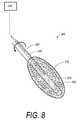
- FIG. 8is a sectional view of an alternative working end with a fluid-expanded elastomeric abrasive cutter that is expandable in transverse section.
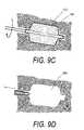
- FIGS. 9A-9Dare sequential views of an fluid-expandable elastomeric cutter being used to abrade a space in cancellous bone, for example, in a vertebra.
- FIG. 10Ais a perspective view of an alternative working end with first and second rotatable abrasive cutter portions that are configured to extend in a plane relative to the instrument axis to create a weakened plane in bone.
- FIG. 10Bis a view of the working end of FIG. 10A in a method of use to abrade and cut a weakened plane in a vertebral cancellous bone.
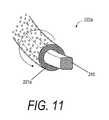
- FIG. 11is a cut-away of an alternative flexible cutter as if taken along line 11 - 11 of FIG. 10A .
- FIG. 1is a schematic view of an exemplary bone cutting system or probe 100 that has handle portion 102 that transitions to elongated extension member 104 that extends along axis 105 .
- the extension member 104carries a distal working end 110 that comprises a high speed elastomeric, abrasive rotational cutter indicated at 112 .
- the handle portion 102can be any suitable assembly for gripping with a human hand and can carry trigger and actuator mechanisms known in the art.
- the elastomeric abrasive cutter 112is fixedly coupled to the distal end of elongated drive member 114 that is rotated at a high speed by a rotation mechanism, such as an air motor or electric motor indicated at 115 .
- the drive member 114rotates in bore 118 in an elongated rigid sleeve 120 that is coupled to handle portion 102 .
- the elongated sleeve 120 and elastomeric cutter 112are configured with dimensions suited for insertion into a vertebra from a posterior transpedicular or extrapedicular approach, with the diameter of the sleeve 120 and cutter 112 ranging between about 1.0 mm and 4.0 mm, and more preferably between 1.5 mm and 3.0 mm.
- the length of the cutter 112ranges from 1 mm to 10 mm, and more preferably from 2 mm to 5 mm.
- the elastomeric cutter 112is fabricated of a resilient polymer (e.g., silicone or urethane) that is embedded with abrasive crystals 122 or the like, for example diamond or other similar particles having a mean cross-section ranging between about 1 micron and 100 microns, and more preferably between about 5 microns and 50 microns.
- the rotation mechanism or motor 115is configured for rotating the elastomeric cutter 112 at speed ranging from about 500 rpm to 400,000 rpm, and more preferably at speeds ranging between about 5,000 rpm and 100,000 rpm.
- the drive member 114has a bore 128 therethrough that allows the probe 100 to be advanced over a guide member such as a wire (not shown).
- the bore 128also optionally can be used for fluid infusion to irrigate the site, and for this reason a fluid source 140 is shown in FIG. 1 .
- the probe or system 100optionally includes a negative pressure source 145 operatively connected to bore 118 in sleeve 120 for aspirating fluid and abraded bone debris from the bone treatment site.
- the distal end portion of sleeve 120can have ports 148 or openings therein to allow fluid and bone debris to be aspirated into bore 118 of sleeve 120 .
- the elastomeric cutter 112can be operated within a selected speed range that preferentially abrades and cuts bone such as cancellous or cortical bone but will not abrade soft tissue.
- This aspect of the inventionis useful, for example, in operations in the interior of a vertebral body, for example when cutting through a cortical wall and inadvertently contacting soft tissue outside the vertebra.
- the systemwill discriminate tissue density and not cut the lower density soft tissue such as ligaments.
- the use of a resilient cutter at selected speeds to discriminate in cutting harder tissue and sparing softer tissuewas disclosed in U.S. Pat. Nos. 4,445,509 and 4,990,134 to David C. Auth, which are incorporated herein by this reference.
- the Auth patentsrelate to endovascular catheter tips that are abrasive for cutting occlusive materials that clog an artery.
- the present inventionis fabricated in the configuration of a rigid probe 100 with dimensions suited for percutaneous insertion into an abnormal vertebra.
- an elastomeric cutter 112 similar to the embodiment shown in FIG. 1can be used to cut one or more straight or curved paths in cancellous bone 149 in vertebral body 150 .
- cutter 112is advanced over a selected straight guide member 152 .
- FIG. 2Billustrates cutter 112 advanced over a curved shape memory alloy guide member 154 .
- the bore 128 in drive member 114is dimensioned to slide and rotate relative to the guide member 152 or 154 .
- the drive member 114can be a helical drive element or braided sleeve that is flexible for rotating the cutter 112 .
- a plurality of paths 155can be cut or abraded by this means with the result shown in FIG. 3 .
- the plurality of paths 155are then filled with a bone cement 158 (e.g., PMMA) injected through introducer sleeve 159 .
- the bone cement 158is adapted to prophylactically treat a vertebra 150 that may be susceptible to a compression fracture.
- FIGS. 4A-4Banother use of elastomeric cutter 112 is shown wherein tip 160 of the cutter is penetrated through the cortical bone wall 162 of vertebra 150 in at least one location 164 to create a weakened region.
- This use of the cutterwill provide a fracturable region or line 165 in the cortical bone ( FIG. 4B ) that will allow for elevation of vertebral endplate 166 a relative to endplate 166 b upon the pressurized introduction of bone fill materials.
- This use of cutter 112 as indicated in FIGS. 4A-4Bis adapted for cases in which a vertebral compression fracture has healed in a collapsed position with the bone portions fusing together.
- the cutter 112thus allows cutting through cortical bone 162 with the cutter abrading bone but discriminating tissue based on density differences so that the cutter does not cut the ligaments 168 as the cutter tip 160 penetrates cortical bone layer 162 . ( FIG. 4A ).
- This method of creating a weakened plane or region 165 in cortical bonewas disclosed by the authors in U.S. Provisional Patent Application Ser. No. 60/622,209 filed Oct. 26, 2004 titled Systems and Methods for Treating Vertebral Fractures, which is incorporated herein by this reference and made a part of this specification.
- FIG. 5depicts another use of elastomeric cutter 112 in a vertebra wherein the working end 110 of the probe 100 is moved laterally and/or translated axially while rotating the elastomeric cutter 112 to abrade and cut a plane P.
- the cuttingcan be done from one or more access paths to the interior of the vertebra 150 to cut a suitable plane P.
- a bone fill materiale.g., PMMA
- increasing injection pressures of the bone fill materialcan be used to apply forces to move the endplates apart to reduce the fracture.
- FIG. 6depicts another probe 180 with an elastomeric cutter 112 similar to that of FIG. 1 .
- the motor-driven drive member 184also functions as a pull-rod to axially compress and move the elastomeric cutter 112 to the shape indicated at 112 ′ wherein the transverse section of the cutter is increased to thereby abrade or cut a larger diameter path in cancellous bone.
- the cutter 112can be an elastomeric monolith of silicone, urethane or the like that is bonded to drive member 184 . It can be understood that the proximal end 186 of cutter 112 will be pushed against the distal end 188 of sleeve 120 to thereby outwardly expand the transverse section of the monolith.
- a central bore in the probeis not shown as in bore 128 in FIG. 1 , but such a feature is optional.
- FIG. 7is a sectional view of another probe 190 with an elastomeric cutter 112 that is similar to that of FIG. 6 .
- the motor-driven drive member 184again functions as a pull-rod to actuate elastomeric cutter 112 to an enlarged transverse section.
- the cutter 112is hollow to allow greater expansion than the version of FIG. 6 .
- elastomeric cutter 112has first and second ends, 191 a and 191 b , that are bonded to first and second collars 192 a and 192 b that cooperate with drive shaft 184 .
- the second collaris bonded to shaft 184 and the first collar included projecting key elements 194 that slide in key slots 196 to key the rotation of cutter 112 to that of the shaft 184 .
- the systemoperates as described above.
- the wall 198 of the elastomeric cutter 112has a plurality of perforations and the interior opening communicates with aspiration ports in a hollow drive shaft and/or in the introducer sleeve. It can be easily understood that an aspiration source and irrigation source as in probe 100 of FIG. 1 can be incorporated into a system using a mechanically expandable elastomeric cutter 112 having a perforated wall.
- FIG. 8is a perspective sectional view of an alternative probe 200 that carries a rotatable elastomeric cutter 112 that is fluid expandable, for example, by inflow of a liquid or a gas from any suitable pressure source 210 .
- the elastomeric cutter 112has a substantially thick expandable wall 212 that carries diamond abrasives as described previously.
- the expandable wallis coupled to shaft 220 having a lumen 232 extending therethrough to deliver fluid from the pressurized source 210 to a chamber 242 in the expandable cutter 112 .
- the shaft 220can be a flexible polymer, a superelastic alloy or the like.
- the probecan have a bore extending therethrough (not shown) for advancing over a straight or curved guide member.
- a plurality of differently shaped guide memberscan be used as shown in FIGS. 2B and 3 to create varied geometry paths.
- an expandable, elastomeric cutter 112can be a resilient polymer without an inflation chamber that is expanded by centrifugal forces resulting from very high rotational speeds, for example 50,000 rpm or higher and can be driven by an air motor.
- the wall of a similar balloon structureis expandable but can still be fluid-permeable to allow leakage of saline or sterile water into the bone being abraded.
- An aspiration sourcecan be coupled to such a working end as described above.
- FIGS. 9A-9Dillustrate an alternative method wherein a fluid-expandable structure with an abrasive surface as in FIGS. 7 and 8 is used to create a space 240 (or multiple spaces) in cancellous bone 149 to receive a volume of bone cement.
- the methodincludes abrading a space in a bone and injecting bone cement under high pressure to distract cortical endplates to restore vertebral height.
- the bone cementis the type described in co-pending U.S. application Ser. Nos. 11/165,651 and 11/165,652 filed Jun. 24, 2005, both titled Bone Treatment Systems and Methods, wherein the bone cement can be altered in viscosity on demand with the application of energy to prevent cement extravasion.
- FIGS. 9A-9Dprovides safe means for creating a space 240 in a bone, for example a substantially large space in vertebral cancellous bone to receive a bone cement.
- a balloonis inserted in a cut or fractured path in cancellous bone 149 and then inflated with very high pressures.
- the bone structureacts akin to any ceramic material and only fractures under very large loads (e.g. up to 300 psi or more in the balloon)—at which time the fracture of cancellous bone is explosive.
- the balloonIn kyphoplasty, the balloon is entirely constrained by the small path in cancellous bone until ever-increasing pressure fractures the cancellous bone resulting in “explosive” expansion of the balloon.
- the explosive expansion of a kyphoplasty ballooncan cause point loading where the balloon contacts the cortical endplates of the vertebra.
- the explosive expansion of the ballooncan easily crack an endplate if the expanded balloon wall is in close proximity to the endplate.
- FIGS. 9A-9Dit is believed for the first time performs “non-explosive” balloon expansion with the interior of a vertebra by configuring the fluid-expandable structure with high speed rotational abrading functionality.
- the inventive systemremoves bone debris by means of irrigation and aspiration to prevent the crushing and compaction of cancellous bone.
- 9A-9Ccan be configured with an pressure source and controller so that the expandable structure is expanded with (i) constant pressure inflows, (ii) constant volume inflows, (iii) a modulated inflow rate or (iv) pulsed inflows to move the expandable structure 112 from a non-expanded condition to an expanded condition over an interval greater than about one tenth of a second. More specifically, the method includes moving the structure 112 from a non-expanded condition to an expanded condition over an interval ranging between about 1/10 of a second and 10 minutes, and more preferably between about 1 second and 5 minutes; and more preferably between about 10 seconds and 2 minutes.
- the systemuses a controller to expand the expandable structure 112 to a first increased transverse dimension (while rotationally abrading bone) and then expansion forces are terminated with the structure partially expanded—followed by at least one other interval to expand the structure to a second transverse dimension and then termination of expansion again while rotationally abrading bone.
- This methodfurther insures that no explosive expansion forces are applied within a vertebral body as occurs with a kyphoplasty-type balloon and method.
- the method of the present inventionallows for expansion of structure 112 in a plurality of intervals to increased dimensions that are a fraction of the most-expanded shape of the expandable structure 112 ( FIGS. 9A-9C ).
- the expandable structure 112can be expanded to 10%-50% of its maximum working volume after which inflows are terminated. Then the structure can be expanded to 20%-60% of its maximum working volume followed by a non-expansion interval, then the structure can be expanded to 30%-70% of its working volume followed by a non-expansion interval, and so forth.
- the controllercan rotate the structure 112 at a selected rpm or a varied rpm within the ranges described above.
- the systemuses fluid expansion to move an expandable structure from a first transverse dimension to a second greater transverse dimension in cancellous bone of a vertebra at low non-explosive fluid inflow pressures while rotationally abrading the cancellous bone.
- the pressurescan be less than 100 psi, or more preferably less than 50 psi, or more preferably less than 25 psi.
- the system pressures used by the inventive methodare far lower than practiced in balloon procedures adapted to crush and compact cancellous bone.
- a method of the inventioncomprises inserting an expandable structure into cancellous bone, and expanding the structure at a selected rate of expansion without compacting the cancellous bone by rotation of an abrasive surfaced structure to thereby cut bone.
- the method of the inventionincludes inserting an expandable structure into cancellous bone, and expanding the structure step-wise to insure that explosive expansion does not occur together with the rotational bone abrading step.
- the methodincludes inserting an expandable structure into cancellous bone, and expanding the structure with fluid inflow pulses that range from 1 Hz to 1,000 Hz to enhance bone abrasion with the surface of the expandable structure. More preferably, the fluid inflows are pulses in the range of 10 to 100 Hz.
- the apparatus of the invention for abrading bonecomprises (a) an elongated member having a first end and a second end, (b) the second end having an expandable cross-section with an abrasive surface, and (c) a rotational drive mechanism coupled to the first end for rotation thereof to abrade a path or a space in a bone.
- the abrasive surfaceis a polymeric material with abrasive particles affixed thereto, such as diamond particles.
- the diamond particlescan be natural monocrystalline diamond, synthetic monocrystalline diamond, polycrystalline diamond or a combination thereof.
- the diamond particleshave a mean dimension ranging from about 1.0 micron to 100 microns.
- FIGS. 10A and 10Billustrate another cutting system and method for cutting a plane P in bone to assist in reducing a vertebral fracture that has healed to some extent.
- FIG. 10Adepicts a bone cutting system 200 with introducer 210 that extends along axis 215 to working end 220 that includes first and second flexible rotational abrading (cutting) elements 222 a and 222 b .
- the systemincludes a rotation mechanism 225 in a handle (not shown) of the device such as an electric motor for rotating the rotational elements 222 a and 222 b .
- Each rotational element 222 a and 222 bhas a proximal end 224 a and 224 b that is coupled to the motor drive and extends through a sleeve 226 a and 226 b in the introducer 210 .
- the rotational elements 222 a and 222 bcan be flexible metal wires, braided wires or braid-reinforces polymeric members.
- the system 200further includes a reciprocating actuator member 240 for outward flexing of the distal end of the rotational elements 222 a and 222 b as shown in FIG. 10A . As can be seen in FIG.
- the distal ends 242 a and 242 b of the rotational elementsare rotatable and secured in collar 244 that is coupled to actuator member 240 .
- the cutter 200can be introduced into a bone in a reduced cross-sectional configuration with the cutting elements 222 a and 222 b in a linear configuration (phantom view). It further can be seen that simultaneous rotation of the cutting elements 222 a and 222 b and actuation by actuator member 240 will allow outward cutting in a plane in cancellous bone.
- 10Billustrates a method of use wherein the system is used to cut a more-or-less horizontal or sagittal plane P in the cancellous bone and can further be used to abrade cortical bone.
- the cutting system 200can be used to create a weakened plane in the bone for enhancing the application of forces in vectors more-or-less perpendicular to the cut plane. Irrigation and aspiration can be used with the cutting system 200 .
- the application of forcescan be created by the inflow of a bone cement, by injection of graft material, by the expansion of a balloon, the injection of filler material into a knit, woven or braided structure or sac, or the use of a mechanical jacking system.
- the cutting elements 222 a and 222 bare indicated as flexible rotating members.
- FIG. 11is a cut-away schematic view of a transverse section of the flexible portion of cutter 222 a (see FIG. 10A ).
- a rotatable sleeve 221 arotates around a flexible rod indicated as a flexible rectangular support member 245 .
- the rectangular support member 245is less adapted to deflect in use since the member 245 does not rotate.
- Other similar non-rotating support memberscan be used that are eternal to the rotatable sleeve 221 a and coupled to the sleeve by flanges.
- the volume of bone cement volumecan comprise a PMMA, monocalcium phosphate, tricalcium phosphate, calcium carbonate, calcium sulphate and hydroxyapatite, or any combination thereof.
- the bone cementalso can carry allograft material, autograft material or any other infill bone infill granular material or scaffold material as in known in the art.
Landscapes
- Health & Medical Sciences (AREA)
- Surgery (AREA)
- Life Sciences & Earth Sciences (AREA)
- Heart & Thoracic Surgery (AREA)
- General Health & Medical Sciences (AREA)
- Engineering & Computer Science (AREA)
- Veterinary Medicine (AREA)
- Biomedical Technology (AREA)
- Public Health (AREA)
- Animal Behavior & Ethology (AREA)
- Orthopedic Medicine & Surgery (AREA)
- Dentistry (AREA)
- Oral & Maxillofacial Surgery (AREA)
- Nuclear Medicine, Radiotherapy & Molecular Imaging (AREA)
- Medical Informatics (AREA)
- Molecular Biology (AREA)
- Hematology (AREA)
- Anesthesiology (AREA)
- Vascular Medicine (AREA)
- Surgical Instruments (AREA)
- Prostheses (AREA)
Abstract
Description
Claims (28)
Priority Applications (1)
| Application Number | Priority Date | Filing Date | Title |
|---|---|---|---|
| US11/282,316US8562607B2 (en) | 2004-11-19 | 2005-11-19 | Bone treatment systems and methods |
Applications Claiming Priority (2)
| Application Number | Priority Date | Filing Date | Title |
|---|---|---|---|
| US62962804P | 2004-11-19 | 2004-11-19 | |
| US11/282,316US8562607B2 (en) | 2004-11-19 | 2005-11-19 | Bone treatment systems and methods |
Publications (2)
| Publication Number | Publication Date |
|---|---|
| US20060149268A1 US20060149268A1 (en) | 2006-07-06 |
| US8562607B2true US8562607B2 (en) | 2013-10-22 |
Family
ID=36641626
Family Applications (1)
| Application Number | Title | Priority Date | Filing Date |
|---|---|---|---|
| US11/282,316Active2031-02-09US8562607B2 (en) | 2004-11-19 | 2005-11-19 | Bone treatment systems and methods |
Country Status (1)
| Country | Link |
|---|---|
| US (1) | US8562607B2 (en) |
Cited By (24)
| Publication number | Priority date | Publication date | Assignee | Title |
|---|---|---|---|---|
| US20130018377A1 (en)* | 2011-07-14 | 2013-01-17 | Alphatec Spine, Inc. | Instrument for removal of material from within a body |
| US20150164562A1 (en)* | 2012-06-01 | 2015-06-18 | Depuy (Ireland) | Surgical instruments |
| US9216195B2 (en) | 2008-02-28 | 2015-12-22 | Dfine, Inc. | Bone treatment systems and methods |
| US9445854B2 (en) | 2008-02-01 | 2016-09-20 | Dfine, Inc. | Bone treatment systems and methods |
| US9592317B2 (en) | 2005-08-22 | 2017-03-14 | Dfine, Inc. | Medical system and method of use |
| US9901657B2 (en) | 2008-10-13 | 2018-02-27 | Dfine, Inc. | System for use in bone cement preparation and delivery |
| US10039584B2 (en) | 2008-04-21 | 2018-08-07 | Dfine, Inc. | System for use in bone cement preparation and delivery |
| US10869689B2 (en) | 2017-05-03 | 2020-12-22 | Medtronic Vascular, Inc. | Tissue-removing catheter |
| US10905440B2 (en) | 2008-09-26 | 2021-02-02 | Relievant Medsystems, Inc. | Nerve modulation systems |
| US11007010B2 (en) | 2019-09-12 | 2021-05-18 | Relevant Medsysterns, Inc. | Curved bone access systems |
| US11065046B2 (en) | 2013-08-08 | 2021-07-20 | Relievant Medsystems, Inc. | Modulating nerves within bone |
| US11160563B2 (en) | 2012-11-05 | 2021-11-02 | Relievant Medsystems, Inc. | Systems for navigation and treatment within a vertebral body |
| US11357534B2 (en) | 2018-11-16 | 2022-06-14 | Medtronic Vascular, Inc. | Catheter |
| US11471210B2 (en) | 2011-12-30 | 2022-10-18 | Relievant Medsystems, Inc. | Methods of denervating vertebral body using external energy source |
| US11596468B2 (en) | 2002-09-30 | 2023-03-07 | Relievant Medsystems, Inc. | Intraosseous nerve treatment |
| US11690667B2 (en) | 2012-09-12 | 2023-07-04 | Relievant Medsystems, Inc. | Radiofrequency ablation of tissue within a vertebral body |
| US11690645B2 (en) | 2017-05-03 | 2023-07-04 | Medtronic Vascular, Inc. | Tissue-removing catheter |
| US11819236B2 (en) | 2019-05-17 | 2023-11-21 | Medtronic Vascular, Inc. | Tissue-removing catheter |
| US12039731B2 (en) | 2020-12-22 | 2024-07-16 | Relievant Medsystems, Inc. | Prediction of candidates for spinal neuromodulation |
| US12082876B1 (en) | 2020-09-28 | 2024-09-10 | Relievant Medsystems, Inc. | Introducer drill |
| US12208194B2 (en) | 2018-06-13 | 2025-01-28 | Stryker European Operations Limited | Bone fragment collector and processor |
| US12274629B2 (en) | 2019-12-18 | 2025-04-15 | Stryker European Operations Limited | Bone fragment collector and processor |
| US12303166B2 (en) | 2008-09-26 | 2025-05-20 | Relievant Medsystems, Inc. | Methods for accessing nerves within bone |
| US12433668B1 (en) | 2021-11-08 | 2025-10-07 | Relievant Medsystems, Inc. | Impedance stoppage mitigation during radiofrequency tissue ablation procedures |
Families Citing this family (61)
| Publication number | Priority date | Publication date | Assignee | Title |
|---|---|---|---|---|
| US8142462B2 (en) | 2004-05-28 | 2012-03-27 | Cavitech, Llc | Instruments and methods for reducing and stabilizing bone fractures |
| FR2871366A1 (en) | 2004-06-09 | 2005-12-16 | Ceravic Soc Par Actions Simpli | PROSTHETIC EXPANSIBLE BONE IMPLANT |
| US7682378B2 (en)* | 2004-11-10 | 2010-03-23 | Dfine, Inc. | Bone treatment systems and methods for introducing an abrading structure to abrade bone |
| US20060229624A1 (en)* | 2005-03-31 | 2006-10-12 | Zimmer Technology, Inc. | Orthopaedic cutting instrument and method |
| US8080061B2 (en)* | 2005-06-20 | 2011-12-20 | Synthes Usa, Llc | Apparatus and methods for treating bone |
| US20070093822A1 (en)* | 2005-09-28 | 2007-04-26 | Christof Dutoit | Apparatus and methods for vertebral augmentation using linked expandable bodies |
| US8157806B2 (en)* | 2005-10-12 | 2012-04-17 | Synthes Usa, Llc | Apparatus and methods for vertebral augmentation |
| US7927361B2 (en)* | 2005-11-29 | 2011-04-19 | Medtronic Xomed, Inc. | Method and apparatus for removing material from an intervertebral disc space, such as in performing a nucleotomy |
| US20070162132A1 (en) | 2005-12-23 | 2007-07-12 | Dominique Messerli | Flexible elongated chain implant and method of supporting body tissue with same |
| US20080027443A1 (en)* | 2006-07-26 | 2008-01-31 | Lambert Systms, L.L.C. | Biocompatible Anchoring Device For A Soft Tissue Graft, Method Of Making And Method Of Using |
| WO2008076330A1 (en) | 2006-12-15 | 2008-06-26 | Soteira, Inc. | Drills and methods for vertebrostenting |
| WO2008097855A2 (en)* | 2007-02-05 | 2008-08-14 | Dfine, Inc. | Bone treatment systems and methods |
| WO2008137428A2 (en) | 2007-04-30 | 2008-11-13 | Dfine, Inc. | Bone treatment systems and methods |
| US20090131952A1 (en) | 2007-05-21 | 2009-05-21 | Brian Schumacher | Delivery system and method for inflatable devices |
| US9510885B2 (en) | 2007-11-16 | 2016-12-06 | Osseon Llc | Steerable and curvable cavity creation system |
| US20090131886A1 (en) | 2007-11-16 | 2009-05-21 | Liu Y King | Steerable vertebroplasty system |
| US20090131867A1 (en) | 2007-11-16 | 2009-05-21 | Liu Y King | Steerable vertebroplasty system with cavity creation element |
| US20090149878A1 (en)* | 2007-12-07 | 2009-06-11 | Csaba Truckai | Bone treatment systems and methods |
| WO2009100200A1 (en)* | 2008-02-08 | 2009-08-13 | Vexim Sas | Devices, systems and methods for creating a surgical plane in a vertebral body |
| WO2009155319A1 (en) | 2008-06-17 | 2009-12-23 | Soteira, Inc. | Devices and methods for fracture reduction |
| US8470043B2 (en) | 2008-12-23 | 2013-06-25 | Benvenue Medical, Inc. | Tissue removal tools and methods of use |
| US9161773B2 (en) | 2008-12-23 | 2015-10-20 | Benvenue Medical, Inc. | Tissue removal tools and methods of use |
| CA2749266C (en)* | 2009-01-13 | 2017-05-09 | Innovative Implant Technology, Llc | Maxillary bone cutting and injection system and method of using the same |
| WO2010094032A2 (en) | 2009-02-16 | 2010-08-19 | Aoi Medical Inc. | Trauma nail accumulator |
| WO2010111246A1 (en) | 2009-03-23 | 2010-09-30 | Soteira, Inc. | Devices and methods for vertebrostenting |
| US20100298832A1 (en) | 2009-05-20 | 2010-11-25 | Osseon Therapeutics, Inc. | Steerable curvable vertebroplasty drill |
| FR2949204B1 (en)* | 2009-08-21 | 2011-10-14 | Snecma | MACHINING MACHINE FOR CMC BY MILLING AND ULTRASOUND ABRASION |
| US9220554B2 (en) | 2010-02-18 | 2015-12-29 | Globus Medical, Inc. | Methods and apparatus for treating vertebral fractures |
| US20110264098A1 (en)* | 2010-02-26 | 2011-10-27 | Cobbs Charles S | Minimally invasive systems, devices, and surgical methods for performing arthrodesis in the spine |
| US9125671B2 (en) | 2010-04-29 | 2015-09-08 | Dfine, Inc. | System for use in treatment of vertebral fractures |
| TWI579007B (en) | 2010-07-02 | 2017-04-21 | 艾格諾福斯保健公司 | Use of bone regenerative material |
| US8414606B2 (en) | 2010-10-22 | 2013-04-09 | Medtronic Xomed, Inc. | Method and apparatus for removing material from an intervertebral disc space and preparing end plates |
| US8814873B2 (en)* | 2011-06-24 | 2014-08-26 | Benvenue Medical, Inc. | Devices and methods for treating bone tissue |
| US9629646B2 (en) | 2012-07-11 | 2017-04-25 | Jens Kather | Curved burr surgical instrument |
| US9480574B2 (en) | 2013-03-14 | 2016-11-01 | Benvenue Medical, Inc. | Spinal fusion implants and devices and methods for deploying such implants |
| US9603610B2 (en)* | 2013-03-15 | 2017-03-28 | DePuy Synthes Products, Inc. | Tools and methods for tissue removal |
| CN108670349B (en) | 2013-04-24 | 2021-06-04 | Tag医疗器材农业合作有限公司 | Device and method for bone material removal |
| EP3057517B1 (en) | 2013-10-15 | 2020-04-08 | Stryker Corporation | Device for creating a void space in a living tissue, the device including a handle with a control knob that can be set regardless of the orientation of the handle |
| FR3015221B1 (en) | 2013-12-23 | 2017-09-01 | Vexim | EXPANSIBLE INTRAVERTEBRAL IMPLANT SYSTEM WITH POSTERIOR PEDICULAR FIXATION |
| US10314605B2 (en) | 2014-07-08 | 2019-06-11 | Benvenue Medical, Inc. | Apparatus and methods for disrupting intervertebral disc tissue |
| BR112017008135B1 (en) | 2014-10-19 | 2022-11-16 | T.A.G. Medical Devices - Agriculture Cooperative Ltd | SET INCLUDING A GUIDANCE SYSTEM AND BONE MATERIAL REMOVAL DEVICE AND METHOD FOR DRILLING A BONE TUNNEL INTO A BONE |
| US10022243B2 (en) | 2015-02-06 | 2018-07-17 | Benvenue Medical, Inc. | Graft material injector system and method |
| JP7007190B2 (en) | 2015-04-09 | 2022-01-24 | ティー.エー.ジー. メディカル デヴァイシス-アグリカルチャー コーポラティヴ リミテッド | Bone material remover and how to use it |
| US10499960B2 (en)* | 2015-07-13 | 2019-12-10 | IntraFuse, LLC | Method of bone fixation |
| EP3799806A1 (en) | 2016-02-11 | 2021-04-07 | T.A.G. Medical Devices - Agriculture Cooperative Ltd. | Bone material removal device |
| EP3448274B1 (en) | 2016-04-24 | 2024-05-15 | T.A.G. Medical Products Corporation Ltd. | Guiding device |
| JP2019534130A (en) | 2016-10-27 | 2019-11-28 | ディーファイン,インコーポレイティド | Articulated osteotome with cement delivery channel |
| CA3041114A1 (en) | 2016-11-28 | 2018-05-31 | Dfine, Inc. | Tumor ablation devices and related methods |
| US10470781B2 (en) | 2016-12-09 | 2019-11-12 | Dfine, Inc. | Medical devices for treating hard tissues and related methods |
| US10660656B2 (en) | 2017-01-06 | 2020-05-26 | Dfine, Inc. | Osteotome with a distal portion for simultaneous advancement and articulation |
| US10758286B2 (en) | 2017-03-22 | 2020-09-01 | Benvenue Medical, Inc. | Minimal impact access system to disc space |
| WO2018232100A1 (en)* | 2017-06-14 | 2018-12-20 | Osteoagra Llc | Stabilization of vertebral bodies with bone particle slurry |
| US12102367B2 (en) | 2017-06-14 | 2024-10-01 | Osteoagra Llc | Method, composition, and apparatus for stabilization of vertebral bodies |
| WO2019148083A1 (en) | 2018-01-29 | 2019-08-01 | Benvenue Medical, Inc. | Minimally invasive interbody fusion |
| WO2019178575A1 (en) | 2018-03-16 | 2019-09-19 | Benvenue Medical, Inc. | Articulated instrumentation and methods of using the same |
| IL280574B2 (en) | 2018-08-01 | 2025-08-01 | Tag Medical Devices Agriculture Coop Ltd | Adjustable drilling device and method for using the same |
| US11937864B2 (en) | 2018-11-08 | 2024-03-26 | Dfine, Inc. | Ablation systems with parameter-based modulation and related devices and methods |
| US11554197B2 (en)* | 2018-11-20 | 2023-01-17 | BioMark, LLC | Device with an open cell element |
| US11849986B2 (en) | 2019-04-24 | 2023-12-26 | Stryker Corporation | Systems and methods for off-axis augmentation of a vertebral body |
| US11986229B2 (en) | 2019-09-18 | 2024-05-21 | Merit Medical Systems, Inc. | Osteotome with inflatable portion and multiwire articulation |
| US12035922B2 (en)* | 2021-04-27 | 2024-07-16 | Globus Medical, Inc. | Bi-directional disk removal and decortication tool |
Citations (83)
| Publication number | Priority date | Publication date | Assignee | Title |
|---|---|---|---|---|
| US3621505A (en)* | 1970-03-12 | 1971-11-23 | Harold Ray Vocker | Dual rotary surface contacting tool |
| US4271839A (en) | 1979-07-25 | 1981-06-09 | Thomas J. Fogarty | Dilation catheter method and apparatus |
| US4294251A (en) | 1978-10-17 | 1981-10-13 | Greenwald A Seth | Method of suction lavage |
| US4338925A (en) | 1979-12-20 | 1982-07-13 | Jo Miller | Pressure injection of bone cement apparatus and method |
| US4445509A (en) | 1982-02-04 | 1984-05-01 | Auth David C | Method and apparatus for removal of enclosed abnormal deposits |
| US4827676A (en)* | 1982-10-14 | 1989-05-09 | Ant Nachrichtentechnik Gmbh | Method of removing the primary protective coating from an optical waveguide |
| US4857045A (en)* | 1987-04-30 | 1989-08-15 | Schneider (Usa) Inc., A Pfizer Company | Atherectomy catheter |
| US4895146A (en)* | 1982-01-25 | 1990-01-23 | Klaus Draenert | Surgical bone-grinding instrument |
| US4969906A (en) | 1987-07-28 | 1990-11-13 | Kronman Joseph H | Bone and bony tissue replacement |
| US4969888A (en) | 1989-02-09 | 1990-11-13 | Arie Scholten | Surgical protocol for fixation of osteoporotic bone using inflatable device |
| US4990134A (en) | 1986-01-06 | 1991-02-05 | Heart Technology, Inc. | Transluminal microdissection device |
| WO1991006713A1 (en) | 1989-10-24 | 1991-05-16 | Groutco (Aust.) Pty. Ltd. | Inflatable ground anchor |
| US5059193A (en) | 1989-11-20 | 1991-10-22 | Spine-Tech, Inc. | Expandable spinal implant and surgical method |
| US5285795A (en) | 1991-09-12 | 1994-02-15 | Surgical Dynamics, Inc. | Percutaneous discectomy system having a bendable discectomy probe and a steerable cannula |
| US5409376A (en)* | 1993-03-10 | 1995-04-25 | Murphy; Quentin M. | Apparatus and process for laser-assisted driling |
| US5431654A (en) | 1991-09-30 | 1995-07-11 | Stryker Corporation | Bone cement injector |
| US5679299A (en) | 1994-03-30 | 1997-10-21 | Northwestern University | Methods of making self-reinforced composition of amorphous thermoplastics |
| US5693099A (en) | 1991-07-11 | 1997-12-02 | Haerle; Anton | Endoprosthesis |
| US5827289A (en) | 1994-01-26 | 1998-10-27 | Reiley; Mark A. | Inflatable device for use in surgical protocols relating to treatment of fractured or diseased bones |
| US5925038A (en)* | 1996-01-19 | 1999-07-20 | Ep Technologies, Inc. | Expandable-collapsible electrode structures for capacitive coupling to tissue |
| US5972015A (en) | 1997-08-15 | 1999-10-26 | Kyphon Inc. | Expandable, asymetric structures for deployment in interior body regions |
| US6048346A (en) | 1997-08-13 | 2000-04-11 | Kyphon Inc. | Systems and methods for injecting flowable materials into bones |
| US6145833A (en)* | 1998-06-02 | 2000-11-14 | Marquip, Inc. | Rotary brush sheet deceleration device |
| US6171312B1 (en) | 1996-07-18 | 2001-01-09 | Implant Innovations, Inc. | Power-driven osteotome tools for compaction of bone tissue |
| US6235043B1 (en) | 1994-01-26 | 2001-05-22 | Kyphon, Inc. | Inflatable device for use in surgical protocol relating to fixation of bone |
| US6248110B1 (en) | 1994-01-26 | 2001-06-19 | Kyphon, Inc. | Systems and methods for treating fractured or diseased bone using expandable bodies |
| US6261289B1 (en) | 1998-10-26 | 2001-07-17 | Mark Levy | Expandable orthopedic device |
| US6296639B1 (en)* | 1999-02-12 | 2001-10-02 | Novacept | Apparatuses and methods for interstitial tissue removal |
| US20010034526A1 (en) | 2000-02-15 | 2001-10-25 | Kuslich Stephen D. | Expandable reamer |
| US6319255B1 (en) | 1996-12-18 | 2001-11-20 | Eska Implants Gmbh & Co. | Prophylactic implant against fracture of osteoporosis-affected bone segments |
| US6332894B1 (en) | 2000-03-07 | 2001-12-25 | Zimmer, Inc. | Polymer filled spinal fusion cage |
| US20020026195A1 (en) | 2000-04-07 | 2002-02-28 | Kyphon Inc. | Insertion devices and method of use |
| US6358254B1 (en) | 2000-09-11 | 2002-03-19 | D. Greg Anderson | Method and implant for expanding a spinal canal |
| US20020082608A1 (en) | 1994-01-26 | 2002-06-27 | Kyphon Inc. | Systems and methods using expandable bodies to push apart cortical bone surfaces |
| US20020099385A1 (en) | 2000-10-25 | 2002-07-25 | Kyphon Inc. | Systems and methods for reducing fractured bone using a fracture reduction cannula |
| US6425923B1 (en) | 2000-03-07 | 2002-07-30 | Zimmer, Inc. | Contourable polymer filled implant |
| US6439439B1 (en) | 2001-01-12 | 2002-08-27 | Telios Orthopedic Systems, Inc. | Bone cement delivery apparatus and hand-held fluent material dispensing apparatus |
| US6440138B1 (en) | 1998-04-06 | 2002-08-27 | Kyphon Inc. | Structures and methods for creating cavities in interior body regions |
| US6443988B2 (en) | 1994-05-06 | 2002-09-03 | Disc Dynamics, Inc. | Mold apparatus and kit for in situ tissue repair |
| US6443967B1 (en)* | 2001-05-03 | 2002-09-03 | Scimed Life Systems, Inc. | Injection moldable feedstock including diamond particles for abrasive applications |
| US6447514B1 (en) | 2000-03-07 | 2002-09-10 | Zimmer | Polymer filled hip fracture fixation device |
| US20020147497A1 (en) | 2001-04-06 | 2002-10-10 | Integrated Vascular Systems, Inc. | Methods for treating spinal discs |
| US6468289B1 (en) | 1990-06-28 | 2002-10-22 | Peter M. Bonutti | Apparatus and method for tissue removal |
| US20020183758A1 (en)* | 2001-06-01 | 2002-12-05 | Middleton Lance M. | Tissue cavitation device and method |
| US20030032929A1 (en) | 1998-12-09 | 2003-02-13 | Mcguckin James F. | Hollow curved superelastic medical needle and method |
| US20030097133A1 (en) | 2001-11-21 | 2003-05-22 | Green James M. | Attachable/detachable reaming head for surgical reamer |
| US20030130664A1 (en) | 1998-08-14 | 2003-07-10 | Kyphon Inc. | Systems and methods for treating vertebral bodies |
| US20030220648A1 (en) | 2000-04-05 | 2003-11-27 | Kyphon Inc. | Methods and devices for treating fractured and/or diseased bone |
| US20040024410A1 (en) | 2002-08-02 | 2004-02-05 | Scimed Life Systems, Inc. | Media delivery device for bone structures |
| US6706069B2 (en) | 2001-09-13 | 2004-03-16 | J. Lee Berger | Spinal grooved director with built in balloon |
| US6712852B1 (en) | 2002-09-30 | 2004-03-30 | Depuy Spine, Inc. | Laminoplasty cage |
| US6719773B1 (en) | 1998-06-01 | 2004-04-13 | Kyphon Inc. | Expandable structures for deployment in interior body regions |
| US20040073308A1 (en) | 2000-07-21 | 2004-04-15 | Spineology, Inc. | Expandable porous mesh bag device and methods of use for reduction, filling, fixation, and supporting of bone |
| US6723095B2 (en) | 2001-12-28 | 2004-04-20 | Hemodynamics, Inc. | Method of spinal fixation using adhesive media |
| US20040092948A1 (en) | 2002-01-11 | 2004-05-13 | Kyphon Inc. | Inflatable device for use in surgical protocol relating to fixation of bone |
| US20040097946A1 (en) | 2002-07-25 | 2004-05-20 | Richard Wolf Gmbh | Device for cutting bones to size |
| US6740093B2 (en) | 2000-02-28 | 2004-05-25 | Stephen Hochschuler | Method and apparatus for treating a vertebral body |
| US20040102845A1 (en) | 2002-11-21 | 2004-05-27 | Reynolds Martin A. | Methods of performing embolism-free vertebroplasty and devices therefor |
| US20040138748A1 (en) | 2000-03-22 | 2004-07-15 | Synthes (Usa) | Plugs for filling bony defects |
| US20040147934A1 (en) | 2002-10-18 | 2004-07-29 | Kiester P. Douglas | Oscillating, steerable, surgical burring tool and method of using the same |
| US20040168698A1 (en)* | 2003-02-04 | 2004-09-02 | L'oreal | Brush for applying substance to eyelashes and/or eyebrows |
| US6790210B1 (en) | 2000-02-16 | 2004-09-14 | Trans1, Inc. | Methods and apparatus for forming curved axial bores through spinal vertebrae |
| US20040186576A1 (en) | 2003-03-20 | 2004-09-23 | Spineco, Inc., An Ohio Corporation | Expandable spherical spinal implant |
| US20040225926A1 (en) | 2003-04-26 | 2004-11-11 | International Business Machines Corporation | Configuring memory for a RAID storage system |
| US20040267271A9 (en) | 1994-01-26 | 2004-12-30 | Kyphon Inc. | Expandable preformed structures for deployment in interior body regions |
| US20040267272A1 (en) | 2003-05-12 | 2004-12-30 | Henniges Bruce D | Bone cement mixing and delivery system |
| US20050010231A1 (en) | 2003-06-20 | 2005-01-13 | Myers Thomas H. | Method and apparatus for strengthening the biomechanical properties of implants |
| US20050015148A1 (en) | 2003-07-18 | 2005-01-20 | Jansen Lex P. | Biocompatible wires and methods of using same to fill bone void |
| US20050055785A1 (en)* | 2003-09-17 | 2005-03-17 | Spooner Gregory Clegg | Sweeping appliance |
| US20050059979A1 (en) | 2003-09-11 | 2005-03-17 | Duran Yetkinler | Use of vibration with orthopedic cements |
| EP1529494A1 (en) | 2003-11-08 | 2005-05-11 | Jürgen Dr. Buchholz | Instrument for treatment of regions of human or animal bones |
| US6923813B2 (en) | 2003-09-03 | 2005-08-02 | Kyphon Inc. | Devices for creating voids in interior body regions and related methods |
| US20050203527A1 (en) | 2004-03-03 | 2005-09-15 | Scimed Life Systems, Inc. | Apparatus and methods for removing vertebral bone and disc tissue |
| US20050209595A1 (en) | 2000-05-09 | 2005-09-22 | Regeneex Ltd. | Expandable devices and methods for tissue expansion, regeneration and fixation |
| US20050222681A1 (en) | 2002-06-17 | 2005-10-06 | Richard Richley | Devices and methods for minimally invasive treatment of degenerated spinal discs |
| US20050245938A1 (en) | 2004-04-28 | 2005-11-03 | Kochan Jeffrey P | Method and apparatus for minimally invasive repair of intervertebral discs and articular joints |
| US20060100635A1 (en) | 1994-01-26 | 2006-05-11 | Kyphon, Inc. | Inflatable device for use in surgical protocol relating to fixation of bone |
| US20060100706A1 (en) | 2004-11-10 | 2006-05-11 | Shadduck John H | Stent systems and methods for spine treatment |
| US7044954B2 (en) | 1994-01-26 | 2006-05-16 | Kyphon Inc. | Method for treating a vertebral body |
| US20060229625A1 (en) | 2004-11-10 | 2006-10-12 | Csaba Truckai | Bone treatment systems and methods |
| US7211085B2 (en)* | 2001-03-01 | 2007-05-01 | Warsaw Orthopedic, Inc. | Dynamic lordotic guard with movable extensions for creating an implantation space posteriorly in the lumbar spine and method for use thereof |
| EP1787593A1 (en) | 2004-05-19 | 2007-05-23 | Sintea Biotech S.p.A. | Device for creating bone cavities |
| US20080208196A1 (en) | 2007-02-26 | 2008-08-28 | Team-At-Work, Inc. | Method and device for restoring spinal disc function |
- 2005
- 2005-11-19USUS11/282,316patent/US8562607B2/enactiveActive
Patent Citations (102)
| Publication number | Priority date | Publication date | Assignee | Title |
|---|---|---|---|---|
| US3621505A (en)* | 1970-03-12 | 1971-11-23 | Harold Ray Vocker | Dual rotary surface contacting tool |
| US4294251A (en) | 1978-10-17 | 1981-10-13 | Greenwald A Seth | Method of suction lavage |
| US4271839A (en) | 1979-07-25 | 1981-06-09 | Thomas J. Fogarty | Dilation catheter method and apparatus |
| US4338925A (en) | 1979-12-20 | 1982-07-13 | Jo Miller | Pressure injection of bone cement apparatus and method |
| US4895146A (en)* | 1982-01-25 | 1990-01-23 | Klaus Draenert | Surgical bone-grinding instrument |
| US4445509A (en) | 1982-02-04 | 1984-05-01 | Auth David C | Method and apparatus for removal of enclosed abnormal deposits |
| US4827676A (en)* | 1982-10-14 | 1989-05-09 | Ant Nachrichtentechnik Gmbh | Method of removing the primary protective coating from an optical waveguide |
| US4990134A (en) | 1986-01-06 | 1991-02-05 | Heart Technology, Inc. | Transluminal microdissection device |
| US4990134B1 (en) | 1986-01-06 | 1996-11-05 | Heart Techn Inc | Transluminal microdissection device |
| US4857045A (en)* | 1987-04-30 | 1989-08-15 | Schneider (Usa) Inc., A Pfizer Company | Atherectomy catheter |
| US4969906A (en) | 1987-07-28 | 1990-11-13 | Kronman Joseph H | Bone and bony tissue replacement |
| US5108404A (en) | 1989-02-09 | 1992-04-28 | Arie Scholten | Surgical protocol for fixation of bone using inflatable device |
| US4969888A (en) | 1989-02-09 | 1990-11-13 | Arie Scholten | Surgical protocol for fixation of osteoporotic bone using inflatable device |
| WO1991006713A1 (en) | 1989-10-24 | 1991-05-16 | Groutco (Aust.) Pty. Ltd. | Inflatable ground anchor |
| US5059193A (en) | 1989-11-20 | 1991-10-22 | Spine-Tech, Inc. | Expandable spinal implant and surgical method |
| US6468289B1 (en) | 1990-06-28 | 2002-10-22 | Peter M. Bonutti | Apparatus and method for tissue removal |
| US6719803B2 (en) | 1990-06-28 | 2004-04-13 | Bonutti 2003 Trust-A | Method for forming and implanting a grafting material containing tissue |
| US5693099A (en) | 1991-07-11 | 1997-12-02 | Haerle; Anton | Endoprosthesis |
| US5285795A (en) | 1991-09-12 | 1994-02-15 | Surgical Dynamics, Inc. | Percutaneous discectomy system having a bendable discectomy probe and a steerable cannula |
| US5431654A (en) | 1991-09-30 | 1995-07-11 | Stryker Corporation | Bone cement injector |
| US5409376A (en)* | 1993-03-10 | 1995-04-25 | Murphy; Quentin M. | Apparatus and process for laser-assisted driling |
| US20020082608A1 (en) | 1994-01-26 | 2002-06-27 | Kyphon Inc. | Systems and methods using expandable bodies to push apart cortical bone surfaces |
| US7044954B2 (en) | 1994-01-26 | 2006-05-16 | Kyphon Inc. | Method for treating a vertebral body |
| US20060100635A1 (en) | 1994-01-26 | 2006-05-11 | Kyphon, Inc. | Inflatable device for use in surgical protocol relating to fixation of bone |
| US6235043B1 (en) | 1994-01-26 | 2001-05-22 | Kyphon, Inc. | Inflatable device for use in surgical protocol relating to fixation of bone |
| US6248110B1 (en) | 1994-01-26 | 2001-06-19 | Kyphon, Inc. | Systems and methods for treating fractured or diseased bone using expandable bodies |
| US20040225296A1 (en) | 1994-01-26 | 2004-11-11 | Kyphon Inc. | Devices and methods using an expandable body with internal restraint for compressing cancellous bone |
| US20040267271A9 (en) | 1994-01-26 | 2004-12-30 | Kyphon Inc. | Expandable preformed structures for deployment in interior body regions |
| US7166121B2 (en) | 1994-01-26 | 2007-01-23 | Kyphon Inc. | Systems and methods using expandable bodies to push apart cortical bone surfaces |
| US6981981B2 (en) | 1994-01-26 | 2006-01-03 | Kyphon Inc. | Inflatable device for use in surgical protocol relating to fixation of bone |
| US5827289A (en) | 1994-01-26 | 1998-10-27 | Reiley; Mark A. | Inflatable device for use in surgical protocols relating to treatment of fractured or diseased bones |
| US5679299A (en) | 1994-03-30 | 1997-10-21 | Northwestern University | Methods of making self-reinforced composition of amorphous thermoplastics |
| US6443988B2 (en) | 1994-05-06 | 2002-09-03 | Disc Dynamics, Inc. | Mold apparatus and kit for in situ tissue repair |
| US5925038A (en)* | 1996-01-19 | 1999-07-20 | Ep Technologies, Inc. | Expandable-collapsible electrode structures for capacitive coupling to tissue |
| US6171312B1 (en) | 1996-07-18 | 2001-01-09 | Implant Innovations, Inc. | Power-driven osteotome tools for compaction of bone tissue |
| US6319255B1 (en) | 1996-12-18 | 2001-11-20 | Eska Implants Gmbh & Co. | Prophylactic implant against fracture of osteoporosis-affected bone segments |
| US20030233096A1 (en) | 1997-06-09 | 2003-12-18 | Kyphon Inc. | Methods and devices for treating bone after high velocity and/or trauma fracture |
| US6048346A (en) | 1997-08-13 | 2000-04-11 | Kyphon Inc. | Systems and methods for injecting flowable materials into bones |
| US7156861B2 (en) | 1997-08-15 | 2007-01-02 | Kyphon Inc. | Expandable structures for deployment in interior body regions |
| US6280456B1 (en) | 1997-08-15 | 2001-08-28 | Kyphon Inc | Methods for treating bone |
| US5972015A (en) | 1997-08-15 | 1999-10-26 | Kyphon Inc. | Expandable, asymetric structures for deployment in interior body regions |
| US20030195547A1 (en) | 1997-08-15 | 2003-10-16 | Kyphon Inc. | Expandable structures for deployment in interior body regions |
| US20070198020A1 (en) | 1998-04-06 | 2007-08-23 | Kyphon Inc. | Apparatus and method for creating cavities in interior body regions |
| US6440138B1 (en) | 1998-04-06 | 2002-08-27 | Kyphon Inc. | Structures and methods for creating cavities in interior body regions |
| US6863672B2 (en) | 1998-04-06 | 2005-03-08 | Kyphon Inc. | Structures and methods for creating cavities in interior body regions |
| US20020188299A1 (en)* | 1998-04-06 | 2002-12-12 | Kyphon Inc. | Structures and methods for creating cavities in interior body regions |
| US20040167561A1 (en) | 1998-06-01 | 2004-08-26 | Kyphon Inc. | Expandable structures for deployment in interior body regions |
| US6719773B1 (en) | 1998-06-01 | 2004-04-13 | Kyphon Inc. | Expandable structures for deployment in interior body regions |
| US6145833A (en)* | 1998-06-02 | 2000-11-14 | Marquip, Inc. | Rotary brush sheet deceleration device |
| US20030130664A1 (en) | 1998-08-14 | 2003-07-10 | Kyphon Inc. | Systems and methods for treating vertebral bodies |
| US6716216B1 (en) | 1998-08-14 | 2004-04-06 | Kyphon Inc. | Systems and methods for treating vertebral bodies |
| US20040210231A1 (en) | 1998-08-14 | 2004-10-21 | Kyphon Inc. | Systems and methods for treating vertebral bodies |
| US6726691B2 (en) | 1998-08-14 | 2004-04-27 | Kyphon Inc. | Methods for treating fractured and/or diseased bone |
| US6261289B1 (en) | 1998-10-26 | 2001-07-17 | Mark Levy | Expandable orthopedic device |
| US20030032929A1 (en) | 1998-12-09 | 2003-02-13 | Mcguckin James F. | Hollow curved superelastic medical needle and method |
| US6296639B1 (en)* | 1999-02-12 | 2001-10-02 | Novacept | Apparatuses and methods for interstitial tissue removal |
| US20010034526A1 (en) | 2000-02-15 | 2001-10-25 | Kuslich Stephen D. | Expandable reamer |
| US6790210B1 (en) | 2000-02-16 | 2004-09-14 | Trans1, Inc. | Methods and apparatus for forming curved axial bores through spinal vertebrae |
| US6740093B2 (en) | 2000-02-28 | 2004-05-25 | Stephen Hochschuler | Method and apparatus for treating a vertebral body |
| US6332894B1 (en) | 2000-03-07 | 2001-12-25 | Zimmer, Inc. | Polymer filled spinal fusion cage |
| US6425923B1 (en) | 2000-03-07 | 2002-07-30 | Zimmer, Inc. | Contourable polymer filled implant |
| US6447514B1 (en) | 2000-03-07 | 2002-09-10 | Zimmer | Polymer filled hip fracture fixation device |
| US20040138748A1 (en) | 2000-03-22 | 2004-07-15 | Synthes (Usa) | Plugs for filling bony defects |
| US20030220648A1 (en) | 2000-04-05 | 2003-11-27 | Kyphon Inc. | Methods and devices for treating fractured and/or diseased bone |
| US20020026195A1 (en) | 2000-04-07 | 2002-02-28 | Kyphon Inc. | Insertion devices and method of use |
| US20050209595A1 (en) | 2000-05-09 | 2005-09-22 | Regeneex Ltd. | Expandable devices and methods for tissue expansion, regeneration and fixation |
| US20040073308A1 (en) | 2000-07-21 | 2004-04-15 | Spineology, Inc. | Expandable porous mesh bag device and methods of use for reduction, filling, fixation, and supporting of bone |
| US6358254B1 (en) | 2000-09-11 | 2002-03-19 | D. Greg Anderson | Method and implant for expanding a spinal canal |
| US20020099385A1 (en) | 2000-10-25 | 2002-07-25 | Kyphon Inc. | Systems and methods for reducing fractured bone using a fracture reduction cannula |
| US7153306B2 (en) | 2000-10-25 | 2006-12-26 | Kyphon Inc. | Systems and methods for reducing fractured bone using a fracture reduction cannula |
| US6439439B1 (en) | 2001-01-12 | 2002-08-27 | Telios Orthopedic Systems, Inc. | Bone cement delivery apparatus and hand-held fluent material dispensing apparatus |
| US7211085B2 (en)* | 2001-03-01 | 2007-05-01 | Warsaw Orthopedic, Inc. | Dynamic lordotic guard with movable extensions for creating an implantation space posteriorly in the lumbar spine and method for use thereof |
| US20020147497A1 (en) | 2001-04-06 | 2002-10-10 | Integrated Vascular Systems, Inc. | Methods for treating spinal discs |
| US6443967B1 (en)* | 2001-05-03 | 2002-09-03 | Scimed Life Systems, Inc. | Injection moldable feedstock including diamond particles for abrasive applications |
| US6746451B2 (en) | 2001-06-01 | 2004-06-08 | Lance M. Middleton | Tissue cavitation device and method |
| US20020183758A1 (en)* | 2001-06-01 | 2002-12-05 | Middleton Lance M. | Tissue cavitation device and method |
| US6706069B2 (en) | 2001-09-13 | 2004-03-16 | J. Lee Berger | Spinal grooved director with built in balloon |
| US20030097133A1 (en) | 2001-11-21 | 2003-05-22 | Green James M. | Attachable/detachable reaming head for surgical reamer |
| US6723095B2 (en) | 2001-12-28 | 2004-04-20 | Hemodynamics, Inc. | Method of spinal fixation using adhesive media |
| US20040092948A1 (en) | 2002-01-11 | 2004-05-13 | Kyphon Inc. | Inflatable device for use in surgical protocol relating to fixation of bone |
| US20050222681A1 (en) | 2002-06-17 | 2005-10-06 | Richard Richley | Devices and methods for minimally invasive treatment of degenerated spinal discs |
| US20040097946A1 (en) | 2002-07-25 | 2004-05-20 | Richard Wolf Gmbh | Device for cutting bones to size |
| US20040024410A1 (en) | 2002-08-02 | 2004-02-05 | Scimed Life Systems, Inc. | Media delivery device for bone structures |
| US6712852B1 (en) | 2002-09-30 | 2004-03-30 | Depuy Spine, Inc. | Laminoplasty cage |
| US20040147934A1 (en) | 2002-10-18 | 2004-07-29 | Kiester P. Douglas | Oscillating, steerable, surgical burring tool and method of using the same |
| US20040102845A1 (en) | 2002-11-21 | 2004-05-27 | Reynolds Martin A. | Methods of performing embolism-free vertebroplasty and devices therefor |
| US20040168698A1 (en)* | 2003-02-04 | 2004-09-02 | L'oreal | Brush for applying substance to eyelashes and/or eyebrows |
| US20040186576A1 (en) | 2003-03-20 | 2004-09-23 | Spineco, Inc., An Ohio Corporation | Expandable spherical spinal implant |
| US20040225926A1 (en) | 2003-04-26 | 2004-11-11 | International Business Machines Corporation | Configuring memory for a RAID storage system |
| US20040267272A1 (en) | 2003-05-12 | 2004-12-30 | Henniges Bruce D | Bone cement mixing and delivery system |
| US20050010231A1 (en) | 2003-06-20 | 2005-01-13 | Myers Thomas H. | Method and apparatus for strengthening the biomechanical properties of implants |
| US20050015148A1 (en) | 2003-07-18 | 2005-01-20 | Jansen Lex P. | Biocompatible wires and methods of using same to fill bone void |
| US6923813B2 (en) | 2003-09-03 | 2005-08-02 | Kyphon Inc. | Devices for creating voids in interior body regions and related methods |
| US20050059979A1 (en) | 2003-09-11 | 2005-03-17 | Duran Yetkinler | Use of vibration with orthopedic cements |
| US20050055785A1 (en)* | 2003-09-17 | 2005-03-17 | Spooner Gregory Clegg | Sweeping appliance |
| EP1529494A1 (en) | 2003-11-08 | 2005-05-11 | Jürgen Dr. Buchholz | Instrument for treatment of regions of human or animal bones |
| US20050203527A1 (en) | 2004-03-03 | 2005-09-15 | Scimed Life Systems, Inc. | Apparatus and methods for removing vertebral bone and disc tissue |
| US20050245938A1 (en) | 2004-04-28 | 2005-11-03 | Kochan Jeffrey P | Method and apparatus for minimally invasive repair of intervertebral discs and articular joints |
| EP1787593A1 (en) | 2004-05-19 | 2007-05-23 | Sintea Biotech S.p.A. | Device for creating bone cavities |
| US20060229625A1 (en) | 2004-11-10 | 2006-10-12 | Csaba Truckai | Bone treatment systems and methods |
| US20060100706A1 (en) | 2004-11-10 | 2006-05-11 | Shadduck John H | Stent systems and methods for spine treatment |
| US20080208196A1 (en) | 2007-02-26 | 2008-08-28 | Team-At-Work, Inc. | Method and device for restoring spinal disc function |
Non-Patent Citations (2)
| Title |
|---|
| Office Action in U.S. Appl. No. 11/271,498, mailed Jan. 22, 2008. |
| Office Action in U.S. Appl. No. 11/271,498, mailed Oct. 27, 2008. |
Cited By (51)
| Publication number | Priority date | Publication date | Assignee | Title |
|---|---|---|---|---|
| US11596468B2 (en) | 2002-09-30 | 2023-03-07 | Relievant Medsystems, Inc. | Intraosseous nerve treatment |
| US9592317B2 (en) | 2005-08-22 | 2017-03-14 | Dfine, Inc. | Medical system and method of use |
| US10080817B2 (en) | 2008-02-01 | 2018-09-25 | Dfine, Inc. | Bone treatment systems and methods |
| US9445854B2 (en) | 2008-02-01 | 2016-09-20 | Dfine, Inc. | Bone treatment systems and methods |
| US9216195B2 (en) | 2008-02-28 | 2015-12-22 | Dfine, Inc. | Bone treatment systems and methods |
| US9821085B2 (en) | 2008-02-28 | 2017-11-21 | Dfine, Inc. | Bone treatment systems and methods |
| US10039584B2 (en) | 2008-04-21 | 2018-08-07 | Dfine, Inc. | System for use in bone cement preparation and delivery |
| US10905440B2 (en) | 2008-09-26 | 2021-02-02 | Relievant Medsystems, Inc. | Nerve modulation systems |
| US12161350B2 (en) | 2008-09-26 | 2024-12-10 | Relievant Medsystems, Inc. | Systems for treating nerves within bone using steam |
| US12329412B2 (en) | 2008-09-26 | 2025-06-17 | Relievant Medsystems, Inc. | Systems for accessing nerves within bone |
| US11471171B2 (en) | 2008-09-26 | 2022-10-18 | Relievant Medsystems, Inc. | Bipolar radiofrequency ablation systems for treatment within bone |
| US12303166B2 (en) | 2008-09-26 | 2025-05-20 | Relievant Medsystems, Inc. | Methods for accessing nerves within bone |
| US9901657B2 (en) | 2008-10-13 | 2018-02-27 | Dfine, Inc. | System for use in bone cement preparation and delivery |
| US9204896B2 (en)* | 2011-07-14 | 2015-12-08 | Alphatec Spine, Inc. | Instrument for removal of material from within a body |
| US20130018377A1 (en)* | 2011-07-14 | 2013-01-17 | Alphatec Spine, Inc. | Instrument for removal of material from within a body |
| US11471210B2 (en) | 2011-12-30 | 2022-10-18 | Relievant Medsystems, Inc. | Methods of denervating vertebral body using external energy source |
| US12059193B2 (en) | 2011-12-30 | 2024-08-13 | Relievant Medsystems, Inc. | Methods of denervating vertebral body using external energy source |
| US10980579B2 (en) | 2012-06-01 | 2021-04-20 | Depuy Ireland Unlimited Company | Implant inserter assembly |
| US9987056B2 (en)* | 2012-06-01 | 2018-06-05 | Depuy Ireland Unlimited Company | Surgical instruments |
| US20150164562A1 (en)* | 2012-06-01 | 2015-06-18 | Depuy (Ireland) | Surgical instruments |
| US11737814B2 (en) | 2012-09-12 | 2023-08-29 | Relievant Medsystems, Inc. | Cryotherapy treatment for back pain |
| US11701168B2 (en) | 2012-09-12 | 2023-07-18 | Relievant Medsystems, Inc. | Radiofrequency ablation of tissue within a vertebral body |
| US11690667B2 (en) | 2012-09-12 | 2023-07-04 | Relievant Medsystems, Inc. | Radiofrequency ablation of tissue within a vertebral body |
| US11160563B2 (en) | 2012-11-05 | 2021-11-02 | Relievant Medsystems, Inc. | Systems for navigation and treatment within a vertebral body |
| US11974759B2 (en) | 2012-11-05 | 2024-05-07 | Relievant Medsystems, Inc. | Methods of navigation and treatment within a vertebral body |
| US11234764B1 (en) | 2012-11-05 | 2022-02-01 | Relievant Medsystems, Inc. | Systems for navigation and treatment within a vertebral body |
| US11291502B2 (en) | 2012-11-05 | 2022-04-05 | Relievant Medsystems, Inc. | Methods of navigation and treatment within a vertebral body |
| US11065046B2 (en) | 2013-08-08 | 2021-07-20 | Relievant Medsystems, Inc. | Modulating nerves within bone |
| US12193719B2 (en) | 2013-08-08 | 2025-01-14 | Relievant Medsystems, Inc. | Modulating nerves within bone |
| US10869689B2 (en) | 2017-05-03 | 2020-12-22 | Medtronic Vascular, Inc. | Tissue-removing catheter |
| US12114887B2 (en) | 2017-05-03 | 2024-10-15 | Medtronic Vascular, Inc. | Tissue-removing catheter with guidewire isolation liner |
| US11690645B2 (en) | 2017-05-03 | 2023-07-04 | Medtronic Vascular, Inc. | Tissue-removing catheter |
| US10925632B2 (en) | 2017-05-03 | 2021-02-23 | Medtronic Vascular, Inc. | Tissue-removing catheter |
| US11871958B2 (en) | 2017-05-03 | 2024-01-16 | Medtronic Vascular, Inc. | Tissue-removing catheter with guidewire isolation liner |
| US11896260B2 (en) | 2017-05-03 | 2024-02-13 | Medtronic Vascular, Inc. | Tissue-removing catheter |
| US10987126B2 (en) | 2017-05-03 | 2021-04-27 | Medtronic Vascular, Inc. | Tissue-removing catheter with guidewire isolation liner |
| US11986207B2 (en) | 2017-05-03 | 2024-05-21 | Medtronic Vascular, Inc. | Tissue-removing catheter with guidewire isolation liner |
| US11051842B2 (en) | 2017-05-03 | 2021-07-06 | Medtronic Vascular, Inc. | Tissue-removing catheter with guidewire isolation liner |
| US12208194B2 (en) | 2018-06-13 | 2025-01-28 | Stryker European Operations Limited | Bone fragment collector and processor |
| US11357534B2 (en) | 2018-11-16 | 2022-06-14 | Medtronic Vascular, Inc. | Catheter |
| US12161359B2 (en) | 2018-11-16 | 2024-12-10 | Medtronic Vascular, Inc. | Catheter |
| US11819236B2 (en) | 2019-05-17 | 2023-11-21 | Medtronic Vascular, Inc. | Tissue-removing catheter |
| US11123103B2 (en) | 2019-09-12 | 2021-09-21 | Relievant Medsystems, Inc. | Introducer systems for bone access |
| US11426199B2 (en) | 2019-09-12 | 2022-08-30 | Relievant Medsystems, Inc. | Methods of treating a vertebral body |
| US11007010B2 (en) | 2019-09-12 | 2021-05-18 | Relevant Medsysterns, Inc. | Curved bone access systems |
| US11202655B2 (en) | 2019-09-12 | 2021-12-21 | Relievant Medsystems, Inc. | Accessing and treating tissue within a vertebral body |
| US11207100B2 (en) | 2019-09-12 | 2021-12-28 | Relievant Medsystems, Inc. | Methods of detecting and treating back pain |
| US12274629B2 (en) | 2019-12-18 | 2025-04-15 | Stryker European Operations Limited | Bone fragment collector and processor |
| US12082876B1 (en) | 2020-09-28 | 2024-09-10 | Relievant Medsystems, Inc. | Introducer drill |
| US12039731B2 (en) | 2020-12-22 | 2024-07-16 | Relievant Medsystems, Inc. | Prediction of candidates for spinal neuromodulation |
| US12433668B1 (en) | 2021-11-08 | 2025-10-07 | Relievant Medsystems, Inc. | Impedance stoppage mitigation during radiofrequency tissue ablation procedures |
Also Published As
| Publication number | Publication date |
|---|---|
| US20060149268A1 (en) | 2006-07-06 |
Similar Documents
| Publication | Publication Date | Title |
|---|---|---|
| US8562607B2 (en) | Bone treatment systems and methods | |
| US8241335B2 (en) | Bone treatment systems and methods for introducing an abrading structure to abrade bone | |
| US20060100706A1 (en) | Stent systems and methods for spine treatment | |
| US11026734B2 (en) | Bone treatment systems and methods | |
| ES2445619T3 (en) | Bone treatment systems and bone filling material | |
| US8932300B2 (en) | Bone treatment systems and methods | |
| US8070753B2 (en) | Bone treatment systems and methods | |
| US8409289B2 (en) | Implants and methods for treating bone | |
| US7717918B2 (en) | Bone treatment systems and methods | |
| US7678116B2 (en) | Bone treatment systems and methods | |
| US20070233250A1 (en) | Systems for treating bone | |
| US20060122614A1 (en) | Bone treatment systems and methods | |
| US20080091207A1 (en) | Bone treatment systems and methods | |
| US20120303036A1 (en) | Bone treatment systems and methods | |
| US20060229628A1 (en) | Biomedical treatment systems and methods |
Legal Events
| Date | Code | Title | Description |
|---|---|---|---|
| AS | Assignment | Owner name:DFINE, INC., CALIFORNIA Free format text:ASSIGNMENT OF ASSIGNORS INTEREST;ASSIGNORS:TRUCKAI, CSABA;SHADDUCK, JOHN H.;REEL/FRAME:020413/0414 Effective date:20071220 | |
| STCF | Information on status: patent grant | Free format text:PATENTED CASE | |
| FEPP | Fee payment procedure | Free format text:PAT HOLDER NO LONGER CLAIMS SMALL ENTITY STATUS, ENTITY STATUS SET TO UNDISCOUNTED (ORIGINAL EVENT CODE: STOL); ENTITY STATUS OF PATENT OWNER: LARGE ENTITY | |
| AS | Assignment | Owner name:WELLS FARGO BANK, NATIONAL ASSOCIATION, AS ADMINISTRATIVE AGENT, NORTH CAROLINA Free format text:SECURITY INTEREST;ASSIGNOR:DFINE, INC.;REEL/FRAME:039481/0260 Effective date:20160706 Owner name:WELLS FARGO BANK, NATIONAL ASSOCIATION, AS ADMINIS Free format text:SECURITY INTEREST;ASSIGNOR:DFINE, INC.;REEL/FRAME:039481/0260 Effective date:20160706 | |
| FPAY | Fee payment | Year of fee payment:4 | |
| MAFP | Maintenance fee payment | Free format text:PAYMENT OF MAINTENANCE FEE, 8TH YEAR, LARGE ENTITY (ORIGINAL EVENT CODE: M1552); ENTITY STATUS OF PATENT OWNER: LARGE ENTITY Year of fee payment:8 | |
| FEPP | Fee payment procedure | Free format text:MAINTENANCE FEE REMINDER MAILED (ORIGINAL EVENT CODE: REM.); ENTITY STATUS OF PATENT OWNER: LARGE ENTITY |