US8562504B2 - Expandable brachytherapy device - Google Patents
Expandable brachytherapy deviceDownload PDFInfo
- Publication number
- US8562504B2 US8562504B2US12/775,636US77563610AUS8562504B2US 8562504 B2US8562504 B2US 8562504B2US 77563610 AUS77563610 AUS 77563610AUS 8562504 B2US8562504 B2US 8562504B2
- Authority
- US
- United States
- Prior art keywords
- lumens
- shaft portion
- brachytherapy
- tubular members
- cavity
- Prior art date
- Legal status (The legal status is an assumption and is not a legal conclusion. Google has not performed a legal analysis and makes no representation as to the accuracy of the status listed.)
- Active, expires
Links
- 238000002725brachytherapyMethods0.000titleclaimsabstractdescription74
- 238000011282treatmentMethods0.000claimsabstractdescription82
- 230000005855radiationEffects0.000claimsabstractdescription60
- 238000000034methodMethods0.000claimsabstractdescription41
- 210000000481breastAnatomy0.000claimsabstractdescription19
- 239000012530fluidSubstances0.000claimsdescription18
- 230000001678irradiating effectEffects0.000claims2
- 210000001519tissueAnatomy0.000description31
- 230000002285radioactive effectEffects0.000description25
- 239000000463materialSubstances0.000description23
- 208000026310Breast neoplasmDiseases0.000description19
- 206010006187Breast cancerDiseases0.000description18
- 206010028980NeoplasmDiseases0.000description14
- 230000007246mechanismEffects0.000description12
- 230000008901benefitEffects0.000description11
- 239000012528membraneSubstances0.000description10
- 238000003780insertionMethods0.000description9
- 230000037431insertionEffects0.000description9
- 239000012781shape memory materialSubstances0.000description9
- 238000001356surgical procedureMethods0.000description8
- 230000004888barrier functionEffects0.000description6
- -1polyethylenePolymers0.000description5
- 238000004873anchoringMethods0.000description4
- 201000011510cancerDiseases0.000description4
- 239000004033plasticSubstances0.000description4
- 229920003023plasticPolymers0.000description4
- 230000008569processEffects0.000description4
- 238000004590computer programMethods0.000description3
- 239000002184metalSubstances0.000description3
- 229910052751metalInorganic materials0.000description3
- HLXZNVUGXRDIFK-UHFFFAOYSA-Nnickel titaniumChemical compound[Ti].[Ti].[Ti].[Ti].[Ti].[Ti].[Ti].[Ti].[Ti].[Ti].[Ti].[Ni].[Ni].[Ni].[Ni].[Ni].[Ni].[Ni].[Ni].[Ni].[Ni].[Ni].[Ni].[Ni].[Ni]HLXZNVUGXRDIFK-UHFFFAOYSA-N0.000description3
- 229910001000nickel titaniumInorganic materials0.000description3
- 238000001959radiotherapyMethods0.000description3
- 208000037803restenosisDiseases0.000description3
- 238000005728strengtheningMethods0.000description3
- 238000002560therapeutic procedureMethods0.000description3
- 206010011732CystDiseases0.000description2
- 239000004696Poly ether ether ketoneSubstances0.000description2
- 239000004698PolyethyleneSubstances0.000description2
- 208000037062PolypsDiseases0.000description2
- FAPWRFPIFSIZLT-UHFFFAOYSA-MSodium chlorideChemical compound[Na+].[Cl-]FAPWRFPIFSIZLT-UHFFFAOYSA-M0.000description2
- 208000002495Uterine NeoplasmsDiseases0.000description2
- 230000005856abnormalityEffects0.000description2
- TZCXTZWJZNENPQ-UHFFFAOYSA-Lbarium sulfateChemical compound[Ba+2].[O-]S([O-])(=O)=OTZCXTZWJZNENPQ-UHFFFAOYSA-L0.000description2
- 238000005452bendingMethods0.000description2
- 208000031513cystDiseases0.000description2
- 230000006378damageEffects0.000description2
- 230000006870functionEffects0.000description2
- 239000000499gelSubstances0.000description2
- 239000011521glassSubstances0.000description2
- 208000014674injuryDiseases0.000description2
- 238000003698laser cuttingMethods0.000description2
- 229920002530polyetherether ketonePolymers0.000description2
- 229920000573polyethylenePolymers0.000description2
- 229920000139polyethylene terephthalatePolymers0.000description2
- 239000005020polyethylene terephthalateSubstances0.000description2
- 239000012857radioactive materialSubstances0.000description2
- 239000010409thin filmSubstances0.000description2
- 230000000451tissue damageEffects0.000description2
- 231100000827tissue damageToxicity0.000description2
- 206010046766uterine cancerDiseases0.000description2
- 229920000049Carbon (fiber)Polymers0.000description1
- 239000004642PolyimideSubstances0.000description1
- 206010060862Prostate cancerDiseases0.000description1
- 208000000236Prostatic NeoplasmsDiseases0.000description1
- 206010039897SedationDiseases0.000description1
- 208000002847Surgical WoundDiseases0.000description1
- RTAQQCXQSZGOHL-UHFFFAOYSA-NTitaniumChemical compound[Ti]RTAQQCXQSZGOHL-UHFFFAOYSA-N0.000description1
- 208000027418Wounds and injuryDiseases0.000description1
- 239000000654additiveSubstances0.000description1
- 239000000853adhesiveSubstances0.000description1
- 230000001070adhesive effectEffects0.000description1
- 230000002411adverseEffects0.000description1
- 238000002399angioplastyMethods0.000description1
- 208000014347autosomal dominant hyaline body myopathyDiseases0.000description1
- 239000000560biocompatible materialSubstances0.000description1
- 238000001574biopsyMethods0.000description1
- 210000001124body fluidAnatomy0.000description1
- 239000010839body fluidSubstances0.000description1
- 238000004364calculation methodMethods0.000description1
- 239000004917carbon fiberSubstances0.000description1
- 239000000919ceramicSubstances0.000description1
- TVFDJXOCXUVLDH-YPZZEJLDSA-Ncesium-131Chemical compound[131Cs]TVFDJXOCXUVLDH-YPZZEJLDSA-N0.000description1
- 238000006243chemical reactionMethods0.000description1
- 230000008602contractionEffects0.000description1
- 229940039231contrast mediaDrugs0.000description1
- 239000002872contrast mediaSubstances0.000description1
- 239000002537cosmeticSubstances0.000description1
- 238000005520cutting processMethods0.000description1
- 229940039227diagnostic agentDrugs0.000description1
- 239000000032diagnostic agentSubstances0.000description1
- 201000010099diseaseDiseases0.000description1
- 208000037265diseases, disorders, signs and symptomsDiseases0.000description1
- 238000009826distributionMethods0.000description1
- 238000002651drug therapyMethods0.000description1
- KBQHZAAAGSGFKK-AHCXROLUSA-Ndysprosium-159Chemical compound[159Dy]KBQHZAAAGSGFKK-AHCXROLUSA-N0.000description1
- 230000000694effectsEffects0.000description1
- 238000005516engineering processMethods0.000description1
- 238000002710external beam radiation therapyMethods0.000description1
- 239000010408filmSubstances0.000description1
- 239000004811fluoropolymerSubstances0.000description1
- 229920002313fluoropolymerPolymers0.000description1
- 239000006260foamSubstances0.000description1
- UIWYJDYFSGRHKR-AHCXROLUSA-Ngadolinium-153Chemical compound[153Gd]UIWYJDYFSGRHKR-AHCXROLUSA-N0.000description1
- 239000007789gasSubstances0.000description1
- 238000002695general anesthesiaMethods0.000description1
- 239000008187granular materialSubstances0.000description1
- 239000007943implantSubstances0.000description1
- 208000015181infectious diseaseDiseases0.000description1
- 229940044173iodine-125Drugs0.000description1
- ZCYVEMRRCGMTRW-YPZZEJLDSA-Niodine-125Chemical compound[125I]ZCYVEMRRCGMTRW-YPZZEJLDSA-N0.000description1
- 229910052741iridiumInorganic materials0.000description1
- GKOZUEZYRPOHIO-UHFFFAOYSA-Niridium atomChemical compound[Ir]GKOZUEZYRPOHIO-UHFFFAOYSA-N0.000description1
- GKOZUEZYRPOHIO-IGMARMGPSA-Niridium-192Chemical compound[192Ir]GKOZUEZYRPOHIO-IGMARMGPSA-N0.000description1
- 230000001788irregularEffects0.000description1
- 230000007794irritationEffects0.000description1
- 239000007788liquidSubstances0.000description1
- 239000006193liquid solutionSubstances0.000description1
- 239000003589local anesthetic agentSubstances0.000description1
- 230000004630mental healthEffects0.000description1
- JITOKQVGRJSHHA-UHFFFAOYSA-Mmonosodium methyl arsenateChemical compound[Na+].C[As](O)([O-])=OJITOKQVGRJSHHA-UHFFFAOYSA-M0.000description1
- 229920003052natural elastomerPolymers0.000description1
- 229920001194natural rubberPolymers0.000description1
- KDLHZDBZIXYQEI-OIOBTWANSA-Npalladium-103Chemical compound[103Pd]KDLHZDBZIXYQEI-OIOBTWANSA-N0.000description1
- 239000002245particleSubstances0.000description1
- 239000008188pelletSubstances0.000description1
- 230000000149penetrating effectEffects0.000description1
- 229920001721polyimidePolymers0.000description1
- 229920000098polyolefinPolymers0.000description1
- 239000004814polyurethaneSubstances0.000description1
- 239000004800polyvinyl chlorideSubstances0.000description1
- 230000002980postoperative effectEffects0.000description1
- 239000000843powderSubstances0.000description1
- 230000002265preventionEffects0.000description1
- 238000005086pumpingMethods0.000description1
- 238000011084recoveryMethods0.000description1
- 230000009467reductionEffects0.000description1
- 229920005989resinPolymers0.000description1
- 239000011347resinSubstances0.000description1
- WUAPFZMCVAUBPE-OIOBTWANSA-Nrhenium-183Chemical compound[183Re]WUAPFZMCVAUBPE-OIOBTWANSA-N0.000description1
- KZUNJOHGWZRPMI-FTXFMUIASA-Nsamarium-145Chemical compound[145Sm]KZUNJOHGWZRPMI-FTXFMUIASA-N0.000description1
- 230000036280sedationEffects0.000description1
- 229910001220stainless steelInorganic materials0.000description1
- 239000010935stainless steelSubstances0.000description1
- 239000000725suspensionSubstances0.000description1
- 229920003051synthetic elastomerPolymers0.000description1
- 239000005061synthetic rubberSubstances0.000description1
- GUVRBAGPIYLISA-UHFFFAOYSA-Ntantalum atomChemical compound[Ta]GUVRBAGPIYLISA-UHFFFAOYSA-N0.000description1
- GZCRRIHWUXGPOV-NJFSPNSNSA-Nterbium-161Chemical compound[161Tb]GZCRRIHWUXGPOV-NJFSPNSNSA-N0.000description1
- 230000001225therapeutic effectEffects0.000description1
- FRNOGLGSGLTDKL-OUBTZVSYSA-Nthulium-170Chemical compound[170Tm]FRNOGLGSGLTDKL-OUBTZVSYSA-N0.000description1
- 239000010936titaniumSubstances0.000description1
- 229910052719titaniumInorganic materials0.000description1
- 230000008733traumaEffects0.000description1
- WFKWXMTUELFFGS-OIOBTWANSA-Ntungsten-181Chemical compound[181W]WFKWXMTUELFFGS-OIOBTWANSA-N0.000description1
- 230000002792vascularEffects0.000description1
- XLYOFNOQVPJJNP-UHFFFAOYSA-NwaterSubstancesOXLYOFNOQVPJJNP-UHFFFAOYSA-N0.000description1
- 229960003267xenon (127xe) gasDrugs0.000description1
- FHNFHKCVQCLJFQ-AHCXROLUSA-Nxenon-127Chemical compound[127Xe]FHNFHKCVQCLJFQ-AHCXROLUSA-N0.000description1
- NAWDYIZEMPQZHO-AHCXROLUSA-Nytterbium-169Chemical compound[169Yb]NAWDYIZEMPQZHO-AHCXROLUSA-N0.000description1
Images


Classifications
- A—HUMAN NECESSITIES
- A61—MEDICAL OR VETERINARY SCIENCE; HYGIENE
- A61N—ELECTROTHERAPY; MAGNETOTHERAPY; RADIATION THERAPY; ULTRASOUND THERAPY
- A61N5/00—Radiation therapy
- A61N5/10—X-ray therapy; Gamma-ray therapy; Particle-irradiation therapy
- A61N5/1001—X-ray therapy; Gamma-ray therapy; Particle-irradiation therapy using radiation sources introduced into or applied onto the body; brachytherapy
- A61N5/1014—Intracavitary radiation therapy
- A61N5/1015—Treatment of resected cavities created by surgery, e.g. lumpectomy
- A—HUMAN NECESSITIES
- A61—MEDICAL OR VETERINARY SCIENCE; HYGIENE
- A61M—DEVICES FOR INTRODUCING MEDIA INTO, OR ONTO, THE BODY; DEVICES FOR TRANSDUCING BODY MEDIA OR FOR TAKING MEDIA FROM THE BODY; DEVICES FOR PRODUCING OR ENDING SLEEP OR STUPOR
- A61M29/00—Dilators with or without means for introducing media, e.g. remedies
- A61M29/02—Dilators made of swellable material
- A—HUMAN NECESSITIES
- A61—MEDICAL OR VETERINARY SCIENCE; HYGIENE
- A61N—ELECTROTHERAPY; MAGNETOTHERAPY; RADIATION THERAPY; ULTRASOUND THERAPY
- A61N5/00—Radiation therapy
- A61N5/10—X-ray therapy; Gamma-ray therapy; Particle-irradiation therapy
- A61N5/1001—X-ray therapy; Gamma-ray therapy; Particle-irradiation therapy using radiation sources introduced into or applied onto the body; brachytherapy
- A61N5/1007—Arrangements or means for the introduction of sources into the body
- A61N2005/1008—Apparatus for temporary insertion of sources, e.g. afterloaders
- A—HUMAN NECESSITIES
- A61—MEDICAL OR VETERINARY SCIENCE; HYGIENE
- A61N—ELECTROTHERAPY; MAGNETOTHERAPY; RADIATION THERAPY; ULTRASOUND THERAPY
- A61N5/00—Radiation therapy
- A61N5/10—X-ray therapy; Gamma-ray therapy; Particle-irradiation therapy
- A61N5/1001—X-ray therapy; Gamma-ray therapy; Particle-irradiation therapy using radiation sources introduced into or applied onto the body; brachytherapy
- A61N5/1014—Intracavitary radiation therapy
- A61N2005/1018—Intracavitary radiation therapy with multiple channels for guiding radioactive sources
- A—HUMAN NECESSITIES
- A61—MEDICAL OR VETERINARY SCIENCE; HYGIENE
- A61N—ELECTROTHERAPY; MAGNETOTHERAPY; RADIATION THERAPY; ULTRASOUND THERAPY
- A61N5/00—Radiation therapy
- A61N5/10—X-ray therapy; Gamma-ray therapy; Particle-irradiation therapy
- A61N5/1001—X-ray therapy; Gamma-ray therapy; Particle-irradiation therapy using radiation sources introduced into or applied onto the body; brachytherapy
- A61N2005/1019—Sources therefor
- A61N2005/1024—Seeds
Definitions
- the inventionrelates to the field of brachytherapy.
- the inventionrelates to an expandable brachytherapy device and methods of using it with the ability to provide a tailored radioactive dose profile.
- brachytherapy devicesfor performing brachytherapy on the body.
- Exemplary devices that are employed in body cavities or cavities created in the body by surgeryinclude, for example, brachytherapy devices for treatment of breast cancer, uterine cancer, prostate cancer, treatment of a cavity left by removal of a tumor, cyst, polyp or similar mass, and treatment or prevention of restenosis.
- Some of these devicesare merely implants that are implanted in a cavity in the body to deliver the treatment.
- certain types of devicesare expandable to allow insertion of the device into the body in an unexpanded state, and subsequent expansion of the device to deliver the brachytherapy.
- Such expandable devicesare particularly useful for the treatment of, for example, breast cancer, vascular restenosis and uterine cancer.
- Breast canceraffects many women. Not only is breast cancer a serious and life threatening illness, quite frequently the methods involved in treating breast cancer can have dramatic life altering cosmetic ramifications for a woman. Treatments, such as mastectomies, involve radical surgical procedures that while saving a patient's life, oftentimes extract a high price on both the physical and mental health of a patient. Other treatment methods may be preferable because of these drawbacks.
- One method of treating breast canceris by subjecting a cancerous tumor to radiation treatment. Although, doing this can be as effective in curing breast cancer as more radical procedures, there is a chance that the intense radiation used in destroying the cancer can adversely affect healthy tissue in the area surrounding the area treated.
- One method for avoiding potential damage to healthy tissueis through the use of special brachytherapy treatment procedures. Applying radiation treatment according to a specialized treatment plan may permit a more effective treatment while minimizing undesirable consequences of that treatment.
- one method of treating the canceris to excise the tumor without removal of the entire breast.
- Excising the tumoris performed in a procedure called a lumpectomy.
- a lumpectomyis the surgical removal of a tumor in the breast, along with a small margin of the surrounding normal breast tissue.
- a lumpectomymay also be called a wide excision biopsy, breast conserving therapy or quadrantectomy (this latter term is used when up to one fourth of the breast is removed).
- the procedureis often performed on women with small or localized breast cancers and can be an attractive surgical treatment option for breast cancer because it allows women to maintain most of their breast after surgery.
- a lumpectomymay be performed using a local anesthetic, sedation, or general anesthesia, depending on the extent of the surgery needed. The surgeon makes a small incision over or near the breast tumor and excises the lump or abnormality along with a margin of an appropriate thickness of normal surrounding breast tissue.
- An exemplary method for performing radiation therapyis to employ an expandable brachytherapy device that has been inserted into the cavity that remains after the lumpectomy.
- One method for using brachytherapy to treat breast cancerinvolves placing a radioactive source within a balloon catheter that has been inserted into the cavity formed by the lumpectomy.
- the radioactive sourceis placed within the central lumen of the balloon catheter, which is generally centered on the longitudinal axis of the expanded device.
- This practiceplaces significant limitations on the ability to customize the treatment for a particular patient. For example, placing the radioactive source within the central lumen of the balloon does not permit the radioactive dosage to be tailored to treat primarily only the areas surrounding the cavity that require irradiation. Also, placement of the radioactive source in the central lumen may result in healthy tissue being exposed to undesirable amounts of radiation during exposure of the tissue requiring treatment and/or underexposure of tissue that is a high risk for cancer recurrence.
- the cavity created by the lumpectomyis generally non-uniform in shape, thereby creating a situation where the distance from the central lumen to tissue at the edge of the cavity may vary at different locations in the cavity, or healthy tissue is located in the treatment region of the radiation field.
- healthy tissuemay be located closer to the central lumen at some locations than at other locations.
- the physicianmay have to use a dose distribution that is less effective than desired.
- the physicianmay employ a dose sufficient to ensure effective treatment, healthy tissue may be damaged.
- many physiciansopt for alternative treatments to avoid the risks associated with the prior art devices.
- the catheter materialmust be stiff enough to maintain structural and functional integrity and flexible enough to minimize discomfort and the chance of injury.
- a broad range of technical propertiescan be achieved by using variations on the thousands of different resins that are current commercially available.
- the cathetersare typically constructed of many different materials such as: polyvinyl chloride (PVC), polyethylene (PE), polyolefin copolymer (POC), nitinol, fluoropolymers, polyurethane (PU), polyetheretherketone (PEEK), polyimide, polyethylene terephthalate (PET), super-elastics, and shape memory materials.
- PVCpolyvinyl chloride
- PEpolyethylene
- POCpolyolefin copolymer
- nitinolfluoropolymers
- PUpolyurethane
- PEEKpolyetheretherketone
- PETpolyimide
- shape memory materialsshape memory materials.
- the materials usedmay also be rendered radio-opaque by the loading of additives such as barium
- Another method for interstitial brachytherapyinvolves the insertion of a plurality of hollow needles or catheters into the breast and through the surgical cavity in the breast, followed by placement of radioactive sources in the needles according to a predetermined treatment plan.
- High dose rate iridium sources as well as seed strandsare examples of the type of radiation sources that may be employed in this type of interstitial brachytherapy.
- U.S. Pat. No. 6,482,142 to Winkler et al.discloses a catheter for use in a method for interstitial brachytherapy in a tumor bed.
- Winklerdiscloses a device, shown in FIG. 4 , having a radiation source 82 made of three wires 84 , 86 , and 88 , each having a plurality of radiation particles.
- Wire 86is a straight wire that extends along the axis of the device and wires 84 and 88 are curved wires that may be made from a shape memory material to allow deformation of the wires for insertion and removal from the catheter. More or fewer wires can be provided.
- FIGS. 2-4show a balloon 36 with radioactive elements 38 attached to the outer surface thereof.
- the surface of the balloonmay be coated with radioactive material. It appears from FIG. 4 , that the radioactive elements 38 expand from a first size, shown in FIG. 2 , to a second, larger size, shown in FIG. 4 , as the balloon 36 expands.
- U.S. Pat. No. 5,863,284 to Kleindiscloses a balloon catheter for use in angioplasty.
- Radioactive sources 30are spaced around the circumference of the balloon.
- the sourcesmay be attached to the balloon ( FIGS. 4 and 4 a ) or may be contained in a sleeve 48 designed to fit over the balloon ( FIGS. 9-10 ).
- a distal portion 18includes a plurality of slits to allow expansion of distal portion 18 when the balloon is inflated to thereby position radioactive elements 30 at substantially uniform intervals around the inflated balloon.
- the distal portion 18includes an elastomeric expansible region 38 which allows expansion of the distal portion 18 when the balloon is expanded to maintain equal spacing of the radioactive elements about the circumference of the balloon.
- the distal portion 18includes a plurality of folds which allow expansion of the distal portion when the balloon is inflated.
- FIGS. 9-10the embodiment shown in FIGS. 9-10 is described.
- a sleeve 48 containing a plurality of foldsis fitted over the balloon. The sleeve 48 is expandable by virtue of the folds when the balloon is expanded.
- the radioactive elementis integrally formed with the balloon such that the radioactive element moves with the balloon as the balloon is expanded.
- the devicemay employ a secondary radiation source in the form of a guide wire inserted into the central lumen of the balloon catheter.
- the devices discussed aboveoffer various methods for using a balloon catheter in brachytherapy, but do not address the provision of customized dosing which can be achieved through the use of certain advantageous features of the present invention discussed below and set out in detail in the detailed description of the preferred embodiments. It is an object of certain embodiments of the invention to provide an apparatus and method for providing tailored brachytherapy treatment.
- the present inventionrelates to a brachytherapy device.
- the deviceincludes a movable surface portion.
- One or more source lumensare situated outside the surface portion of the device and extend a distance sufficient to permit a radiation source to be loaded into the one or more source lumens from outside the body after the device is positioned inside a body or surgical cavity for therapy.
- One or more sources of radiationmay be placed within one or more of the source lumens to provide a customized radiation dose to a treatment area.
- One advantage of the present inventionis that the sources of radiation may be placed at different locations along the length of each source lumen for the same or different time periods to allow for customization of the dose delivered to the treatment area.
- the present inventionrelates to a method of providing brachytherapy.
- the methodinvolves the step of inserting a brachytherapy device into a body or surgical cavity.
- the brachytherapy devicehas one or more source lumens located outside a movable surface portion of the device.
- the methodfurther includes the steps of moving the surface portion within the cavity and placing one or more radioactive sources within at least one of the source lumens to provide a customized radiation dose to a treatment area.
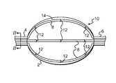
- FIG. 1shows a side view of an expanded device in accordance with a first embodiment of the present invention.
- FIG. 2shows a cross-sectional view of the proximal portion of the expanded device taken along line II-II of FIG. 1 .
- FIG. 3shows the balloon catheter of FIGS. 1-2 located in a cavity of a patient.
- FIG. 4shows a side view of an alternative embodiment of an expanded device with the tubes attached to the movable surface portion.
- FIG. 5is a cross-sectional view taken along V-V of FIG. 4 .
- FIG. 6shows a side view of an alternative embodiment of an expandable device with lumens attached only to proximal and distal portions of the device.
- FIG. 7shows a front view of a manifold for use in the device of the invention.
- FIG. 8Ashows a side view of a cylinder in the unexpanded stated formed by a plurality surface portions hingedly attached to one another.
- FIG. 8Bshows the same side view of the cylinder of FIG. 8A in the expanded state.
- FIG. 8Cshows a view of the proximal end of the cylinder of FIGS. 8A-8B .
- FIG. 8Dshows a conical expander for use in expansion of the device of FIGS. 8A-8C .
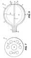
- FIG. 9shows a side view of an expandable device provided with an attachment sleeve for attachment of the expander to the expandable surface portion.
- FIGS. 10A-10Bshow longitudinal cross-sectional views of one embodiment of the expandable device shown in FIG. 9 employing flexible rods to expand the expandable surface portion, with FIG. 10A showing the device in the unexpanded state and FIG. 10B showing the device in the expanded state.
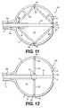
- FIG. 11shows a longitudinal cross-sectional view of another embodiment of the expandable device shown in FIG. 9 employing centrally located linkage arms to expand the expandable surface portion.
- FIG. 12shows a longitudinal cross-sectional view of yet another embodiment of the expandable device shown in FIG. 9 employing linkage arms to expand the expandable surface portion.
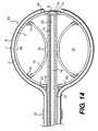
- FIG. 13shows a side view of another embodiment of an expandable device provided with internal expansion means to expand the expandable surface portion.
- FIG. 14shows a longitudinal cross-sectional view of one embodiment of the expandable device shown in FIG. 13 employing flexible rods to expand the expandable surface portion.
- FIG. 15shows a longitudinal cross-sectional view of another embodiment of the expandable device shown in FIG. 13 employing a wire mesh to form the expandable surface portion.
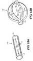
- FIGS. 16A-16Bshow another embodiment of an expandable device which employs a shape memory material, in the unexpanded and expanded positions, respectively.
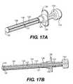
- FIG. 17Ashows an isometric view of another embodiment of an expandable device in non-expanded position.
- FIG. 17Bshows a cross sectional view of the device shown in FIG. 17A .
- FIG. 17Cshows an isometric view of another embodiment of an expandable device in an expanded position.
- FIG. 17Dshows a cross section view of the expanded device shown in FIG. 17C .
- FIG. 18Ashows an alternative embodiment of a mechanism for expanding a device.
- FIG. 18Bshows the mechanism in FIG. 18A in an expanded position.
- FIG. 19Ashows an alternative embodiment of a mechanism for expanding a device.
- FIG. 19Bshows a cross sectional view of the mechanism shown in FIG. 19A
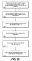
- FIG. 20shows a schematic representation of a method for using a brachytherapy device in accordance with the present invention.
- a brachytherapy deviceis provided with an internal lumen and includes a surface portion that is movable.
- One or more source lumensare situated outside the movable surface portion of the device and extend a distance sufficient to permit a radiation source to be loaded into the one or more source lumens from outside the body after the device is positioned in an existing body cavity or surgical cavity created by a surgical procedure for therapy.
- the devices of the present inventionare applicable to both interstitial and inter-cavital brachytherapy procedures.
- One or more sources of radiationmay be placed within one or more of the internal and source lumens to provide a customized radiation dose to a treatment area.
- the brachytherapy deviceis a balloon catheter 10 that includes a movable surface portion 2 formed by the surface of a balloon 14 .
- balloon 14 of balloon catheter 10is in the inflated state.
- Balloon catheter 10has a proximal portion 4 , and a distal portion 6 .
- Proximal portion 4is of sufficient length to extend from balloon 14 to a location outside the body when balloon 14 is positioned within a surgical or body cavity.
- Distal portion 6provides a location for securing tubes 8 , which define external source lumens 7 , to balloon catheter 10 .
- Tubes 8may be secured to proximal and distal portions 4 , 6 of balloon catheter 10 by any suitable means such as an adhesive, melt bonding, staples, clips, or other conventional securing mechanisms. Tubes 8 may also be formed integrally with one or both of proximal and distal portions 4 , 6 of balloon catheter 10 . In yet another embodiment, Tubes 8 are slidably secured to one or both of proximal and distal portions 10 within a manifold 30 , such as that shown in FIG. 7 , which forms part of one or both of proximal and distal portions 4 , 6 . In this manner, slack in tubes 8 may be taken up by sliding movement of a portion of tubes 8 through manifold 30 as the movable surface portion 2 moves. Manifold 30 may be provided at either the proximal portion 4 or distal portion 6 of the device.
- balloon catheter 10is provided with a plurality of external source lumens 7 defined by tubes 8 which are attached to the proximal and distal portions 4 , 6 of balloon catheter 10 , by a suitable attachment means.
- Tubes 8may have any cross-sectional shape, such as, for example, round, oval, elliptical, square, rectangular, triangular, pentagonal, hexagonal, ribbed, etc.
- Preferred tubes 8are round, oval or elliptical to avoid any corners or edges that might catch during insertion or retraction of the brachytherapy device into or out of the body or surgical cavity, but may also employ strengthening ribs with rounded edges, if desired.
- Source lumens 7may also have any cross-sectional shape, including at least round, oval, elliptical, square, rectangular, triangular, pentagonal, hexagonal, etc. Source lumens 7 are provided for the purpose of receiving one or more radiation sources for treatment of the patient.
- the brachytherapy devicemay include any number of external source lumens 7 , and may include, for example, 1-source lumens 7 , 2-14 20 source lumens 7 , or, optionally, 4-16 source lumens 7 . Different treatment circumstances may dictate the use of different numbers of source lumens 7 depending on, for example, the size of the surgical or body cavity, and the treatment plan.
- One or more radiation sourcesmay be inserted into each of source lumens 7 to provide a customized treatment as described in greater detail below.
- tubes 8are positioned in predetermined locations relative to a reference location, such as the longitudinal axis of balloon catheter 10 , so that dose calculations are based on an accurate representation of the location of source lumens 7 and hence the radiation sources inserted into source lumens 7 .
- tubes 8are not attached to movable surface portion 2 of balloon 14 , which allows tubes 8 to move relative to movable surface portion 2 of balloon 14 .
- Tubes 8may be secured to movable surface portion 2 by a suitable securing means such as tack bonding or using a loop 12 .
- Loops 12may be attached at any location on movable surface portion 2 . As shown, loops 12 are attached midway between proximal portion 4 and distal portion 6 .
- Loops 12are attached to movable surface portion 2 and each loop 12 surrounds a tube 8 to retain tube 8 in close proximity to movable surface portion 2 in the area of loop 12 .
- Loops 12are shown with a minimal length but loops 12 may also extend some length in the axial direction. Contact between loop 12 and tube surface 16 of tube 8 restricts the movement of tube 8 in a radial direction relative to movable surface portion 2 .
- Loops 12may be attached to movable surface portion 2 by any suitable, conventional securing means.
- Loops 12may be made of either a rigid material or a flexible material, though loops 12 , in the embodiment shown, are made from a semi-rigid or flexible material that is biocompatible since loops 12 will contact body tissue during use of the device.
- tubes 8are free to move in the axial direction relative to movable surface portion 2 , which allows slack in tubes 8 to be taken up during inflation of balloon 14 , thereby preventing substantial deformation of source lumens 7 as a result of movement of movable surface portion 2 .
- the longitudinal axis of balloon catheter 10runs from the center of proximal portion 4 to the center of distal portion 6 .
- Slack in tubes 8may be provided in a number of different ways. For example, the length of tubes 8 that extends from proximal portion 4 to distal portion 6 may be selected to provide slack in that portion of tubes 8 .
- tubes 8are slidably secured at the proximal portion 4 and have sufficient length between proximal portion 4 and distal portion 6 to conform to the movable surface portion 2 when balloon 14 is in the inflated condition.
- tubes 8instead of attaching tubes 8 to proximal portion 4 , tubes 8 can be attached to a movable attachment location, which is associated with, or forms part of, proximal portion 4 . In this manner, slack in tubes 8 can be provided outside the body or surgical cavity instead of between proximal portion 4 and distal portion 6 , thereby resulting in a potential reduction in the diameter of balloon catheter 10 that has to pass through the incision to be inserted into the body.
- the movable attachment locationmay be located at the proximal portion 4 for sliding movement in a direction substantially parallel to the longitudinal axis of the device.
- the slackcan also be provided at the distal portion 6 of the device by providing the movable attachment portion at the distal portion 6 of the device.
- Another possibilityis to pass the proximal end of tubes 8 through a manifold 30 , such as that shown in FIG. 7 , and allow tubes 8 to slide within manifold 30 in order to provide the required slack.
- tubes 8are rigidly attached to manifold 30 and manifold 30 is movable to provide the required slack.
- any suitable, conventional sourcemay be employed.
- a wire source or a catheter-mounted sourcemay be employed.
- Radioactive seedsmay be attached to a device suitable for advancement through lumens 7 , 18 for delivering the brachytherapy.
- Exemplary radiation sources that may be employedare described in U.S. Pat. Nos. 5,199,939 and 4,282,781, and pending U.S. patent application Ser. No. 09/858,366, the disclosures of which are hereby incorporated by reference for the purpose of describing the details of a suitable radiation source.
- the radiation sourceis made of iridium-192.
- radioactive isotopessuch as palladium-103, iodine-125, cesium-131, rhenium-183, tungsten-181, thulium-170, ytterbium-169, terbium-161, dysprosium-159, gadolinium-153, samarium-145 and xenon-127.
- FIG. 2shows a cross-sectional view of proximal portion 4 taken along the line II-II of FIG. 1 .
- Balloon catheter 10is provided with an internal lumen 18 and an inflation lumen 25 that are together defined by a tube 19 .
- Inflation lumen 25is used for inflating balloon 14 of balloon catheter 10 .
- Inflation lumen 25is provided with a barrier 26 , such as a check valve, luer actuated valve, or other suitable means, which permits inflation of balloon 14 via inflation lumen 25 , when in an open position, and which retains fluid in balloon 14 when in a closed position.
- Barrier 26is also adapted to open to permit deflation of balloon 14 at the end of the procedure in order to facilitate removal of balloon catheter 10 from the surgical or body cavity.
- Balloon catheter 10is typically inflated by filling balloon 14 with a saline solution 9 in order to inflate the balloon 14 once it is located in the cavity left by the lumpectomy. Additional means for inflation may be used including contrast media for increased visibility, gels with a proper viscosity, as well as some types of soft, natural or synthetic rubbers, elastomeric materials, small pellets, spheres, granules, powders, suspensions, gas generated from chemical reactions, and foams.
- the fluid inflation mechanismmay include a syringe, a gel dispensing tube, or similar, conventional apparatus. The fluid inflation mechanism may be integrated into the device, or it may be provided as a separate device. In a preferred embodiment, balloon 14 is inflated until it compresses at least some of the tissue margins in the cavity.
- Internal lumen 18may be used for a variety of different purposes. Internal lumen 18 could be used for insertion of a guide wire or stiffening spine, for example, should these be required for a particular procedure. Alternatively, a radiation source may be inserted via internal lumen 18 as part of the treatment procedure. In an alternative embodiment, inflation lumen 25 and internal lumen 18 are formed as a single lumen, which may be used both for inflation of balloon 14 and insertion of a radiation source or other device.
- barrier 26can be selected to allow a radiation source to pass through without permitting back flow of fluid out of balloon 14 , or, barier 26 can be advanced to a location closer to distal portion 6 such that it would not be necessary to pass the radiation source through barrier 26 in order to insert it into the single central lumen to deliver a dose of radiation to the patient.
- FIG. 3shows a view of a breast after a lumpectomy has been performed with balloon catheter 10 of FIGS. 1-2 inserted and inflated in the cavity left by the lumpectomy. From FIG. 3 it is apparent that the tissue boundary 28 that forms the cavity 29 left by the lumpectomy is typically non-uniform in shape. As a result, there is a need to customize the radiation dose delivered to the tissue to take into account not only the non-uniform shape of the cavity, but also to ensure that high-risk areas are sufficiently irradiated and that other healthy tissue receives the least possible radiation dose to prevent or minimize undesirable tissue damage.
- proximal portion 4 of balloon catheter 10is adapted for attachment to a device for filling the balloon, such as a syringe or other suitable pumping or transfer device.
- a syringemay be employed to fill balloon 14 with saline solution via inflation lumen 25 , as shown in FIG. 5 , and/or may be employed to after load one or more radioactive sources into source lumens 7 and/or internal lumen 18 , as shown in FIG. 5 , particularly if the radioactive source is to be provided as a fluid.
- Any suitable, conventional afterloadermay be employed with the device of the present invention, such as those that are commercially available from Nucletron B.V. (Netherlands) and Varian Medical Systems, Inc. (Palo Alto, Calif.).
- Proximal portion 4may be connected to an afterloader using a manifold connector similar to the manifold 30 depicted in FIG. 7 below.
- FIGS. 4-5show an alternative embodiment of balloon catheter 10 .
- tube surface 16 of each tube 8may be attached to movable surface portion 2 of balloon 14 via a flexible attachment 22 .
- the entire length of tube surface 16may be attached to movable surface portion 2 from proximal portion 4 to distal portion 6 via flexible attachment 22 .
- tube surface 16may be attached at one or more attachment locations 20 located on movable surface portion 2 of balloon 14 via flexible attachments 22 .
- tube 8is shown attached to movable surface portion 2 at two attachment locations 20 via flexible attachments 22 .
- flexible attachments 22may be fabricated from a material that is more flexible than the material employed to fabricate tubes 8 .
- Tubes 8may be made from a relatively rigid, crush-resistant material that allows radial bending of tubes 8 , as shown in the inflated position of FIG. 1 , but tends to resist deformation of tubes 8 in a manner that prevents or minimizes deformation of source lumens 7 . Since flexible attachments 22 are more flexible than tubes 8 , flexible attachments 22 will preferentially deform, e.g. by stretching, during inflation of balloon 14 , to thereby retain tubes 8 in close proximity to movable surface portion 2 , without causing substantial deformation of tubes 8 or source lumens 7 . Tubes 8 may also incorporate directional strengthening or stiffening ribs in order to maintain radial positioning about the surface of the movable surface portion.
- tubes 8may be formed integrally with movable surface portion 2 , though this embodiment is less preferred since it may result in some deformation of tube 8 and hence source lumens 7 during inflation of balloon 14 .
- the means for attaching tubes 8 to movable surface portion 2allow some movement of tubes 8 relative to movable surface portion 2 such that deformation of tubes 8 thereby deforming source lumens 7 , as a result of the inflation of balloon 14 , is prevented or minimized. It is also within the scope of the present invention to apply a combination of flexible attachments 22 and loops 12 .
- FIG. 6shows another alternative embodiment wherein tubes 8 are not secured to movable surface portion 2 , but rather are only attached to distal and proximal portions 4 , 6 of device 10 .
- This embodimentprovides the most flexibility to tubes 8 .
- tubes 8can be fabricated from a relatively rigid material and are sized such that tubes 8 form a substantially tight fit with movable surface portion 2 when balloon 14 is inflated, or incorporate directional stiffening ribs, in order to best locate tubes 8 at a predetermined location relative to the longitudinal axis of balloon catheter 10 .
- tubes 8While it is preferable to provide some additional stability to tubes 8 by securing tubes 8 to movable surface portion 2 as described above, thereby ensuring that tubes 8 are always located substantially precisely at a predetermined location relative to the longitudinal axis of balloon catheter 10 , other means such as material selection or tube geometry and directional strengthening or stiffening ribs can be employed if desired.
- FIG. 7shows a front view of a manifold 30 which can form part of a manifold connector for connecting proximal portion 4 to an afterloader, or manifold 30 may be used to secure tubes 8 in position relative to proximal portion 4 of balloon catheter 10 .
- Manifold 30includes a structure 36 that defines passages 32 for receiving tubes 8 of the balloon catheter 10 .
- Structure 36also defines a central lumen 34 through which can be passed, for example, a central tube 19 housing the inflation lumen 25 and internal lumen 18 .
- Central lumen 34can alternatively form an integral part of a combined inflation and internal lumen, when the inflation and internal lumens are combined in a single lumen, as described above.
- Manifold 30can be employed to provide slack in tubes 8 as described above.
- tubes 8can be inserted through passages 32 and be allowed to freely move relative to manifold 30 to provide the required slack.
- tubes 8may be affixed to manifold 30 and manifold 30 may be movable relative to the device 10 to provide the required slack in tubes 8 .
- manifold 30is of sufficient thickness that passages 32 have sufficient length to permit tubes 8 to slide some distance within passages 32 , without disengaging from manifold 30 , to provide the required slack in tubes 8 .
- a combination of the manifold 30 , a plurality of tubes 8 and a distal attachment portioncan be provided as a separate device that can later be combined with an inflatable balloon inserted through central lumen 34 in manifold 30 .
- brachytherapy device of the present inventionhas been described above with reference to several different embodiments of balloon catheters 10 .
- the deviceneed not be a balloon catheter.
- movable surface portion 2can be provided by a movable or expandable mechanical device, rather than being formed by an inflatable balloon.
- FIGS. 8A-8DOne suitable device is shown in FIGS. 8A-8D .
- the devicecan include a cylinder 100 having a proximal end 101 and being formed from several distinct surface portions 102 that are attached to one another by, for example, hinges 104 .
- the cylinder 100is shown in the unexpanded position in FIGS. 8A and 8C and in the expanded position in FIG. 8B .
- Cylinder 100is provided with an opening 106 that leads to an inner chamber defined by interior surfaces 108 into which a conical expander 110 may be inserted in order to expand the surface portions 102 by contact between the outer surface 111 of conical expander 110 and interior surfaces 108 as the conical expander is passed through opening 106 .
- a conical expander 110may be inserted into the inner chamber defined by interior surfaces 108 .
- the greater the expansion of the cylinder 100 since outer surface 111 of conical expander 110will force the surface portions 102 outward by exertion of force on interior surfaces 108 of cylinder 100 .
- the movable surface portions 102 of the deviceare actuated by a simple mechanical means, rather than by an inflatable balloon.
- This devicecan be provided in a variety of shapes, other than cylindrical, to meet the requirements for a particular treatment. Other, conventional devices that provide movable surface portions can also be employed.
- FIG. 9shows a side view of expandable device 40 in an expanded state and having a proximal portion 4 and a distal portion 6 .
- Expandable device 40includes an expandable structure 47 that forms an expandable surface portion 2 and has an interior surface 3 .
- Expandable device 40is provided with a plurality of attachment sleeves 42 which are secured to expandable surface portion 2 of expandable structure 47 .
- a plurality of flexible tubes 8are secured to the expandable structure 47 via attachment sleeves 42 in a manner whereby tubes 8 can slide within attachment sleeves 42 to provide for relative movement between tubes 8 and expandable structure 47 .
- Tubes 8extend along the expandable surface portion 2 and terminate at distal end 6 of expandable device 40 .
- Tubes 8may be provided with tube end plugs 68 to prevent wire 41 or source 43 from exiting distal ends of tubes 8 during treatment and to prevent body fluids from entering lumens.
- At distal end 6 of expandable device 40there may be provided an attachment membrane 44 to which tubes 8 may be attached in any suitable manner Attachment membrane 44 is, in turn, secured to central tube 19 , shown in FIGS. 10A-12 to thereby provide structural support to the distal ends of tubes 8 .
- expandable surface portion 2is not expanded by inflation, but is instead expanded by a mechanical expander.
- FIGS. 10A-12discussed in detail below, show three different embodiments of mechanical expanders for use with the expandable device 40 , each of which utilizes attachment sleeves 42 shown in FIG. 9 .
- FIGS. 10A-10Bshow a longitudinal cross-sectional view of one embodiment of an expandable device 40 as shown in FIG. 9 .
- FIG. 10Ashows the expandable device 40 in the unexpanded state
- FIG. 10Bshows the expandable device 40 in the expanded state.
- attachment sleeves 42are each secured to an equatorial tube spacing belt 56 in any suitable manner, which tube spacing belt 56 , in turn, is secured to expandable structure 47 .
- Attachment sleeves 42operate to both secure tubes 8 to expandable structure 47 and to assist in guiding expansion of expandable structure 47 .
- Tube spacing belt 56is secured to expandable structure 47 in any suitable manner, such as by being integrally formed with expandable structure 47 , or by being bonded, stitched, and fastened, etc. to expandable structure 47 .
- the mechanical expander of FIGS. 10A and 10Bincludes four expander rods 46 each of which is secured at the proximal end 59 thereof to a movable member such as a sliding sleeve 58 by any suitable means such as by affixation of the proximal ends of expander rods 46 in slots 60 provided in sliding sleeve 58 .
- a movable membersuch as a sliding sleeve 58
- Different numbers of expander rods 46may be employed.
- Distal ends 45 of expander rods 46are secured to tube spacing belt 56 in any suitable manner such as by insertion into flexible rod receptacles 48 formed integrally with tube spacing belt 56 , as shown.
- the mechanical expander of FIGS. 10A and 10Boperates via the manipulation of sliding sleeve 58 located around central tube 19 in the proximal portion 4 of expandable device 40 .
- sliding sleeve 58is moved relative to tube 19 towards distal end 6 of expandable device 40 .
- Moving sliding sleeve 58forces the proximal ends 59 of rods 46 to move towards the distal end 6 of expandable device 40 . Since distal ends 45 of rods 46 are fixed to expandable structure 47 , this will cause both expansion of expandable structure 47 and bending of rods 46 , as shown.
- An optional binding ring 62may be used to secure tubes 8 in an approximately cylindrical shape at the proximal portion 4 of the device 40 .
- Rod spacing lines 52are an optional feature that may be used to maintain a desired spacing between rods 46 and central tube 19 .
- Rod spacing line 52is attached to rods 46 at attachment points 54 and to central tube 19 for the purpose of maintaining a desired spacing between rods 46 and central tube 19 during expansion of expandable device 40 .
- Rod spacing lines 52are sufficiently flexible that lines 52 can bend to be substantially parallel to central tube 19 when the device 40 is in the unexpanded state.
- lines 52may be rigid, in which case lines 52 should be hingedly or flexibly connected to central tube 19 and rods 46 to allow for different angles between lines 52 , central tube 19 and rods 46 during expansion of expandable device 40 .
- Expandable device 40may be used in the same manner as balloon catheter 10 discussed above in order to treat the tissue in close proximity to a body or surgical cavity. After expansion of expandable device 40 , an afterloader is used for inserting a source wire 41 or a source 43 into source lumens 7 and/or internal lumen 18 , within tubes 8 and 19 respectively.
- expandable structure 47need not be fluid tight and thus may take on a variety of alternative forms.
- expandable structure 47may be made from mesh, a perforated sheet material or some other fluid permeable structure.
- FIG. 11 and FIG. 12are alternative embodiments of the expandable device 40 of FIG. 9 which use linkage arms 80 , rather than expander rods 46 , in order to expand expandable structure 47 .
- Alternative expansion mechanisms using various conventional forms of linkage armsare also possible.
- Linkage arms 80may be constructed of plastic, metal, carbon fibers, ceramics, super-elastics, shape memory materials, etc. Linkage arms 80 secure and guide tubes 8 during expansion of expandable structure 47 as a result of the attachment of linkage arms 80 to expandable structure 47 via pivot points 82 located at the locations of attachment sleeves 42 .
- Linkage arms 80are attached at their proximal ends 81 to slidable sleeve 58 via additional pivot points 83 , and at their distal ends 85 to the distal portion 6 of expandable device 40 via additional pivot points 87 .
- Pivot points 87may be attached to central tube 19 , as shown.
- sliding sleeve 58is moved towards distal end 6 of expandable device 40 from a first position to a second position. Sliding sleeve 58 is also connected to tubes 8 via tube connecting member 84 . Moving sliding sleeve 58 towards distal end 6 causes linkage arms 80 to pivot about pivot points 83 , 87 at pivot points 82 . This causes pivot points 82 to move outwards to the position shown in FIG. 11 to thereby expand the expandable structure 47 .
- rigid linkage arms 90are attached at one end to sliding sleeve 58 via pivot points 92 and are attached to expandable structure 47 at the locations of attachment sleeves 42 via pivot points 93 .
- Rigid linkage arms 90secure and guide tubes 8 via attachment sleeves 42 during the expansion of expandable structure 47 .
- sliding sleeve 58is moved towards distal end 6 of expandable device 40 from a first position to a second position. Moving sliding sleeve 58 towards distal end 6 causes rigid linkage arms 90 to pivot about pivot points 92 , 93 and thereby cause expansion of the expandable structure 47 .
- FIG. 13shows a side view of an expandable device 64 where tubes 8 are secured directly to outer surface 2 of expandable structure 47 .
- Expandable device 64is not inflated and is instead expanded with an internal mechanical expander.
- FIGS. 14 and 15discussed in detail below, show alternative embodiments of mechanical expanders for use with expandable device 64 of FIG. 13 .
- FIG. 14shows a cross-sectional view of one embodiment of an expander for the expandable device 64 shown in FIG. 13 .
- the expander of FIG. 14includes a plurality of support rods 66 attached to a sliding sleeve 57 via flexible attachments which may be flexible attachment receptacles 70 , as shown in FIG. 14 .
- Flexible attachment receptacles 70enable the proximal ends 65 of support rods 66 to be positioned at different angles relative to sliding sleeve 57 during the expansion process, while remaining attached to sliding sleeve 57 .
- proximal ends 65 of support rods 66may be substantially parallel to the longitudinal axis of sliding sleeve 57 .
- proximal ends 65 of support rods 66may be substantially perpendicular to the longitudinal axis of sliding sleeve 57 .
- support rods 66are secured to a distal attachment fitting 78 .
- Distal attachment fitting 78includes a central tube attachment portion 71 for supporting the distal end of central tube 19 .
- Sliding sleeve 57may extend the length of central tube 19 in order to provide additional support for expandable device 64 during the process of expansion.
- Expansionis accomplished by moving sliding sleeve 57 towards distal end 6 to cause support rods 66 to bend away from central tube 19 , as shown in FIG. 14 .
- Attached to expandable support rods 66is a loose thin film, mesh or similar material, which forms expandable structure 47 .
- binding ring 62is used to secure sliding sleeve 57 and tubes 8 in place for after-loading.
- optional secondary support rods 76can be used in order to provide additional structural support during the mechanical expansion.
- Secondary support rods 76are attached to support rods 66 via flexible attachment receptacles 74 and are secured to sliding sleeve 57 via sleeve attachment portions 72 .
- Flexible attachment receptacles 74enable secondary support rods 76 to flexibly move during the expansion of expandable structure 47 .
- Sleeve attachment portions 72act to secure and guide secondary support rods 72 so that they assist in providing structural support to the support rods 66 so that a substantially spherical shape is achieved when expandable structure 47 is fully expanded.
- expandable device 64The nature of the means for expansion in expandable device 64 shown in FIG. 14 permits expandable device 64 to be expanded without the need for an inflation fluid. This enables the usage of thin film membrane or a mesh for the expandable structure 47 that may have reduced radiation attenuation properties and which need not be fluid tight.
- the mechanical means used for expanding expandable device 64means that central tube 19 does not require an inflation lumen 25 .
- FIG. 15shows a cross-sectional view of the expandable device 64 shown in FIG. 13 .
- wire mesh 86which can also be a cage or slit tubing, is expanded from a cylindrical shape that loosely conforms to the shape of central tube 19 to the spherical shape shown in FIG. 15 .
- Wire mesh 86is attached to sliding sleeve 57 at its proximal end 89 and to central tube 19 at its distal end.
- Wire mesh 86is constructed from a rigid plastic material or tempered metal, super-elastic, or a shape memory material that is flexible enough to bend, but rigid enough to be able to expand expandable structure 47 to form a substantially spherical shape.
- other geometriesmay be formed instead of a sphere depending on the needs of treatment and/or cavity shape.
- Other shapesmay include, for example, pear-shaped, elliptical, triangular, rectangular, irregular, or cylindrical.
- sliding sleeve 57is moved towards distal end 6 of expandable device 64 to thereby exert pressure on the proximal end 89 of wire mesh 86 thereby causing wire mesh 86 to bend from a substantially straight configuration to the curved configuration shown in FIG. 15 , thereby expanding expandable structure 47 .
- the movable memberis described as a slidable sleeve 57 , 58 that moves towards the distal end 6 of the expandable device 40 , 64 from a first position to a second position in order to effectuate expansion of the expandable structure 47 .
- various other types of movable membersmay be employed in the context of the present invention. For example, similar results can be achieved by constructing the structure such that the movable member moves away from the distal end 6 of expandable device 40 , 64 to effectuate expansion of expandable structure 47 .
- different types of movable membersmay be employed, other than a slidable sleeve.
- the movable membermay be cylindrical device in an embodiment where no central tube is employed.
- the movable membermay also be in the form of a plurality of finger-like elements, each of which engages the proximal end of the support rod.
- Other variations on the shape and structure of the movable memberare possible, so long as the movable member engages and exerts force on the proximal ends of the support rods to cause expansion of the expandable structure.
- the same devicemay naturally reside in the expanded form and the movable structure may be employed to exert force to return the shape of the device to a cylindrical form, for example. Referring now to FIGS.
- the device 120includes an inner tube 122 of shape memory material that has been heat treated to provide the desired shape memory, in this case a hemispherical shape as can be seen in FIG. 16B .
- inner tube 122Mounted on the outside of inner tube 122 are a cap 133 and a plurality of semi-rigid or flexible tubes 124 , each of which defines a source lumen 126 there through.
- the inner tube 122 and flexible tubes 124are confined within an outer tube 128 which may be made from a relatively rigid, biocompatible material such as titanium, stainless steel and other conventional materials.
- Inner tube 122may be formed by providing a tube-shaped shape memory material, laser cutting the tube into a plurality of expandable arms 123 by cutting slots between the arms 123 and heat treating the arms 123 to provide the desired shape, e.g. hemispherical in this case.
- the device 120is inserted into the surgical or body cavity in the unexpanded state shown in FIG. 16A .
- outer tube 128is retracted in the proximal direction to the position shown in FIG. 16B , whereupon expandable arms 123 expand to the hemispherical position shown in FIG. 16B by virtue of their shape memory characteristics.
- Thiscauses tubes 124 to also take a hemispherical shape thereby positioning source lumens 126 closely adjacent to the tissue to be treated.
- slackmay be provided in tubes 124 at the proximal end in any of the manners described above with respect to other embodiments of the device of the present invention.
- the outer tube 128may be returned to its original position to return the device to the unexpanded state of FIG. 16A for retraction of the device from the body or surgical cavity.
- inner tube 122may define a central source lumen 127 . The inner tube 122 may move in relation to the expandable arms 123 during expansion of the device 120 causing the central source lumen 127 to axially shorten (relative to the spherical portion) during expansion.
- Expandable arms 123may be covered by a film, mesh or balloon, not shown, located between expandable arms 123 and flexible tubes 124 to thereby provide a continuous movable surface portion, if desired for a particular treatment.
- FIGS. 17A-17Dshow alternative embodiments that are similar to the embodiments shown in FIGS. 16A-16B .
- the embodiment shown in FIGS. 17A-17Dincludes finger grips 130 , plunger 132 , and anchoring cap 135 .
- the expansion and contraction of the deviceis controlled by central control rod 131 , shown in FIG. 16B .
- Central control rod 131may define a central lumen 127 which can be used as an additional source lumen during the treatment procedure.
- Central control rod 131is attached to expandable arms 123 via cap 133 . Expandable arms 123 can be formed by partially or wholly splitting a tube, for example, by laser cutting or other similar processes.
- outer tube 128which functions like a manifold, is fixed and can temporarily be held in place using finger grips 130 .
- Outer tube 128may also be provided with indicia identifying one or more of the flexible tubes 124 .
- Finger grips 130can be removable or non-removable.
- Central control rod 131is fixed to cap 133 , but is free to slide axially inside outer tube 128 .
- central control rod 131is retracted in the proximal direction to the position shown in FIGS. 17C and 17D using plunger 132 . This moves the expandable arms 123 to the expanded position shown in FIGS.
- control rod 131may be locked in position via a locking mechanism facilitated by friction, interference, rotation, an expanding collar, a thread, or other appropriate, conventional locking mechanism.
- a strain relief piece(not shown, with a predetermined radius can be employed at the proximal and/or distal end of the device to keep flexible tubes 124 from kinking.
- Plunger 132can be removable or permanently affixed, and/or flexible or rigid.
- Plunger 132can be in the form of a hand controlled rod, a kinematic mechanism, a pneumatic mechanism, or other device employing mechanical advantage that can operate via being pushed, pulled, twisted, or bent.
- a membrane 134made of woven mesh or polymeric material to help sculpt tissue in the body or surgical cavity.
- This membranecan be either elastic or flexible.
- the membranecan also be either liquid-tight or breathable.
- Finger grips 130can also act as an anchoring cap or flap to restrict motion of the device in and out of the entry site.
- the anchoring cap 135could also be a device that slides along the length of outer tube 128 and is then fixed/locked to outer tube 128 and sutured to the skin.
- Anchoring cap 135or, alternatively, a flap would restrict motion of the device in and out of the body entry site. This should reduce the rate of infection.
- the flapcan be an extruded portion of the shaft.
- Sheath 136may be made of an expandable material, for example, elastic, a un-folding sheet (i.e. parachute-like: that opens by unfolding from a tightly folded shape into a conformed shape), or some conformable structure.
- the sheath 136would act as a barrier between the device and the body or surgical cavity to limit tissue ingrowth into the device and/or to act as a barrier to retain liquid inside the device. This may reduce irritation to the surrounding skin during treatment and retraction of the device from the body or surgical cavity, as well as provide a spacing structure to reduce the dose gradient in the treatment zone.
- Sheath 136may also be made of a bio-absorbable material that could remain in the cavity after the device is removed. The sheath may be coated with an appropriate material to further reduce adhesion to tissue and thereby minimize trauma.
- FIGS. 18A and 18Bshow an alternative embodiment of expandable arms 123 .
- expandable arms 123are hourglass-shaped. Expandable arms 123 of this embodiment, may be made by removing material from tube 140 .
- Tube 140can be constructed of plastic or a shape memory material such as nitinol.
- Hinge 137forms a living hinge that enables expandable arms 123 to expand to form the spherical shape shown in FIG. 18B when actuated by a movable member.
- the membranecan be made of woven mesh or polymeric material to help sculpt tissue in the body or surgical cavity. This membrane can be either elastic or flexible.
- the membranecan also be either liquid-tight or breathable.
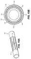
- FIGS. 19A and 19Bshow an alternative embodiment of expandable arms 123 .
- expandable arms 123may be made by making longitudinal slices 139 a tube 140 constructed of thin-walled material such as metal.
- Hinge 137is a living hinge that enables expandable arms 123 to expand when actuated by a movable member.
- FIG. 19Bshows a cross-sectional view of the device shown in FIG. 19A .
- non-spherical shapesmay also be employed throughout the embodiments and may be controlled as necessary to fill the particular cavity in question.
- Sophisticated computer programsexist for modeling radiation dosages and dose rates. Such computer programs are currently in use for brachytherapy treatment planning. It is contemplated the device of the present invention, when used in combination with such a treatment planning tool, can provide significant advantages over prior art devices. Specifically, the computer program can be employed to take into account a variety of factors that may affect the treatment such as the shape of the cavity left by the lumpectomy, the distance to the tissue to be treated, the desired depth of tissue irradiation, the existence of areas of healthy or different tissue for which it is desirable to reduce or minimize the radiation dose, etc. Using these parameters, it is possible to create a customized treatment plan that can be carried out using the device of the present invention.
- the design of the device of the present inventionprovides a number of advantageous features that can be exploited in the treatment planning.
- the location of source lumens 7 on the outside of movable surface portion 2allows the positioning of the radioactive source in close proximity to the treatment area with a minimal amount of intervening structure and/or fluid reducing the shielding and/or attenuation of radiation by the structure of the device itself.
- Another significant advantage of the device of the present inventionis that it presents a large number of different locations where the radioactive source can be positioned to deliver the radiation dose. Not only can the source be positioned in any of the source lumens or the internal or inflation lumen, but the source can also be positioned at any location along the length of any of these lumens.
- different length sourcescan be employed within the various lumens to alter the dose pattern.
- sources of different activitiescan be used simultaneously or sequentially in one or more of the lumens to further customize the treatment. In this manner, far more precise dosing can be provided than in prior art brachytherapy devices. As a result, the device of the present invention will be useful in a significantly larger number of procedures, due to the flexibility that it provides in dosing the patient.
- the device of the present inventioncan be customized in various ways for specific patients or treatments.
- the devicemay be made in different lengths to accommodate different depths of body or surgical cavities.
- the devicemay be fabricated with different sizes and/or shapes of movable surface portions to accommodate different sized body or surgical cavities.
- the device of the present inventionoffers several advantages in use.
- One important advantageis that it permits a very high degree of dose customization for particular treatment plans.
- Another advantageis that the device of the present invention can be implanted for lengthy periods without causing a significant disruption in the patient's life to thereby permit treatments over a period of days or even weeks.
- This advantageis realized because the proximal portion of the device that extends out of the body or surgical cavity can easily be secured and hidden, for example, under the armpit of a breast cancer patient, while the device is implanted.
- the present inventionprovides the ability to easily customize the length of the device for body or surgical cavities located at different depths in the body since it is possible to cut the tubes to a desired length for use.
- a lumpectomyis performed on a patient's breast.
- a surgeonmakes a small incision over or near the breast tumor and excises the lump or abnormality along with a margin of appropriate thickness of normal surrounding breast tissue.
- the patientmay now undergo radiation treatment using a brachytherapy device in accordance with the present invention.
- the treatmentcan usually be shortened to, for example, twice daily for five days.
- the device of the present inventionmay be used to provide a boost radiation treatment to the lumpectomy site typically following external beam radiation.
- FIG. 20shows a schematic representation of one method for using a brachytherapy device in accordance with the present invention.
- at least the portion of the brachytherapy device of the invention, including the movable surface portion 2is inserted via a surgical incision made in the breast into the cavity in the breast that remains after a lumpectomy.
- movable surface portions 2are moved within the cavity to position source lumens 7 closer to tissue boundary 28 .
- one or more radioactive sourcesare loaded into one or more lumens 7 , 18 .
- Loadingmay be dictated, for example, by a predetermined treatment plan.
- Step 506can involve one or more sub-steps, depending on the complexity of the treatment plan.
- the same or different sourcesmay be inserted into different tubes 8 , at different locations along the lengths of the tubes 8 and/or for different durations, as explained above.
- the one or more radioactive source(s)are removed from lumens 7 , 18 to conclude the treatment.
- the movable surface portions 2are returned to their original position and at step 512 the brachytherapy device is retracted from the body or surgical cavity. Steps 502 - 512 can be repeated as needed.
- the method of the present inventionmay further include an additional step of preparing a treatment plan to be followed in step 506 , if desired.
- a brachytherapy device of the present inventionhas been described in the context of breast cancer brachytherapy, it is to be understood that the various devices of the present invention can be employed in any type of interstitial brachytherapy wherein a device is inserted into a surgical cavity.
- the device of the present inventionmay also be employed in intra-cavital brachytherapy in an existing body cavity.
- the devices of the present inventionmay be employed for inter-uterine brachytherapy, esophageal brachytherapy, nasal-pharyngeal brachytherapy, rectal brachytherapy, or for treatment after removal of a tumor, cyst, polyp or other mass, thereby creating a surgical cavity.
- the devices and methods of the present inventionhave been described with reference to breast cancer brachytherapy, it is to be understood that these devices are applicable for other types of brachytherapy treatment involving insertion of the brachytherapy device into a body cavity or a surgical cavity created by a surgical procedure. These devices or methods may also be employed for the delivery of various drug therapies or diagnostic agents desired for the treatment of various other disease states.
Landscapes
- Health & Medical Sciences (AREA)
- Engineering & Computer Science (AREA)
- Biomedical Technology (AREA)
- Life Sciences & Earth Sciences (AREA)
- Animal Behavior & Ethology (AREA)
- Veterinary Medicine (AREA)
- Public Health (AREA)
- General Health & Medical Sciences (AREA)
- Radiology & Medical Imaging (AREA)
- Nuclear Medicine, Radiotherapy & Molecular Imaging (AREA)
- Pathology (AREA)
- Heart & Thoracic Surgery (AREA)
- Surgery (AREA)
- Vascular Medicine (AREA)
- Anesthesiology (AREA)
- Hematology (AREA)
- Radiation-Therapy Devices (AREA)
Abstract
Description
Claims (29)
Priority Applications (3)
| Application Number | Priority Date | Filing Date | Title |
|---|---|---|---|
| US12/775,636US8562504B2 (en) | 2004-11-05 | 2010-05-07 | Expandable brachytherapy device |
| US13/861,195US9623260B2 (en) | 2004-11-05 | 2013-04-11 | Expandable brachytherapy device |
| US14/794,551US9808650B2 (en) | 2004-11-05 | 2015-07-08 | Expandable brachytherapy device |
Applications Claiming Priority (4)
| Application Number | Priority Date | Filing Date | Title |
|---|---|---|---|
| US62535504P | 2004-11-05 | 2004-11-05 | |
| US11/266,994US7662082B2 (en) | 2004-11-05 | 2005-11-04 | Expandable brachytherapy device |
| US12/493,884US8690746B2 (en) | 2004-11-05 | 2009-06-29 | Expandable brachytherapy device |
| US12/775,636US8562504B2 (en) | 2004-11-05 | 2010-05-07 | Expandable brachytherapy device |
Related Parent Applications (1)
| Application Number | Title | Priority Date | Filing Date |
|---|---|---|---|
| US12/493,884ContinuationUS8690746B2 (en) | 2004-11-05 | 2009-06-29 | Expandable brachytherapy device |
Related Child Applications (1)
| Application Number | Title | Priority Date | Filing Date |
|---|---|---|---|
| US13/861,195ContinuationUS9623260B2 (en) | 2004-11-05 | 2013-04-11 | Expandable brachytherapy device |
Publications (2)
| Publication Number | Publication Date |
|---|---|
| US20100222628A1 US20100222628A1 (en) | 2010-09-02 |
| US8562504B2true US8562504B2 (en) | 2013-10-22 |
Family
ID=36317220
Family Applications (10)
| Application Number | Title | Priority Date | Filing Date |
|---|---|---|---|
| US11/266,994Active2027-01-30US7662082B2 (en) | 2004-11-05 | 2005-11-04 | Expandable brachytherapy device |
| US11/682,681ActiveUS7497819B2 (en) | 2004-11-05 | 2007-03-06 | Expandable brachytherapy device |
| US11/688,033ActiveUS7497820B2 (en) | 2004-11-05 | 2007-03-19 | Expandable brachytherapy device |
| US12/493,884Active2027-04-19US8690746B2 (en) | 2004-11-05 | 2009-06-29 | Expandable brachytherapy device |
| US12/692,289Active2026-09-25US8398534B2 (en) | 2004-11-05 | 2010-01-22 | Expandable brachytherapy device |
| US12/694,741Active2026-07-28US8684899B2 (en) | 2004-11-05 | 2010-01-27 | Expandable brachytherapy device |
| US12/710,308Active2026-05-30US8568284B2 (en) | 2004-11-05 | 2010-02-22 | Expandable brachytherapy device |
| US12/775,636Active2026-07-30US8562504B2 (en) | 2004-11-05 | 2010-05-07 | Expandable brachytherapy device |
| US13/861,195ActiveUS9623260B2 (en) | 2004-11-05 | 2013-04-11 | Expandable brachytherapy device |
| US14/794,551ActiveUS9808650B2 (en) | 2004-11-05 | 2015-07-08 | Expandable brachytherapy device |
Family Applications Before (7)
| Application Number | Title | Priority Date | Filing Date |
|---|---|---|---|
| US11/266,994Active2027-01-30US7662082B2 (en) | 2004-11-05 | 2005-11-04 | Expandable brachytherapy device |
| US11/682,681ActiveUS7497819B2 (en) | 2004-11-05 | 2007-03-06 | Expandable brachytherapy device |
| US11/688,033ActiveUS7497820B2 (en) | 2004-11-05 | 2007-03-19 | Expandable brachytherapy device |
| US12/493,884Active2027-04-19US8690746B2 (en) | 2004-11-05 | 2009-06-29 | Expandable brachytherapy device |
| US12/692,289Active2026-09-25US8398534B2 (en) | 2004-11-05 | 2010-01-22 | Expandable brachytherapy device |
| US12/694,741Active2026-07-28US8684899B2 (en) | 2004-11-05 | 2010-01-27 | Expandable brachytherapy device |
| US12/710,308Active2026-05-30US8568284B2 (en) | 2004-11-05 | 2010-02-22 | Expandable brachytherapy device |
Family Applications After (2)
| Application Number | Title | Priority Date | Filing Date |
|---|---|---|---|
| US13/861,195ActiveUS9623260B2 (en) | 2004-11-05 | 2013-04-11 | Expandable brachytherapy device |
| US14/794,551ActiveUS9808650B2 (en) | 2004-11-05 | 2015-07-08 | Expandable brachytherapy device |
Country Status (1)
| Country | Link |
|---|---|
| US (10) | US7662082B2 (en) |
Cited By (2)
| Publication number | Priority date | Publication date | Assignee | Title |
|---|---|---|---|---|
| US20100130807A1 (en)* | 2004-11-05 | 2010-05-27 | Theragenics Corporation | Expandable brachytherapy device |
| US11383093B1 (en) | 2019-12-06 | 2022-07-12 | Hoseon LEE | Radiation release capsule |
Families Citing this family (135)
| Publication number | Priority date | Publication date | Assignee | Title |
|---|---|---|---|---|
| US20050131269A1 (en)* | 1995-06-07 | 2005-06-16 | Talmadge Karen D. | System and method for delivering a therapeutic agent for bone disease |
| DE60324448D1 (en) | 2002-09-10 | 2008-12-11 | Cianna Medical Inc | brachytherapy |
| US8328710B2 (en)* | 2002-11-06 | 2012-12-11 | Senorx, Inc. | Temporary catheter for biopsy site tissue fixation |
| US6923754B2 (en)* | 2002-11-06 | 2005-08-02 | Senorx, Inc. | Vacuum device and method for treating tissue adjacent a body cavity |
| US6749555B1 (en)* | 2003-02-13 | 2004-06-15 | Proxima Therapeutics, Inc. | System and method for the treatment of spinal metastases |
| US20080214887A1 (en)* | 2003-06-18 | 2008-09-04 | Heanue Joseph A | Brachytherapy apparatus and method using off-center radiation source |
| US7563222B2 (en) | 2004-02-12 | 2009-07-21 | Neovista, Inc. | Methods and apparatus for intraocular brachytherapy |
| EP1720608B1 (en) | 2004-02-12 | 2010-11-17 | NeoVista, Inc. | Apparatus for intraocular brachytherapy |
| MXPA06010653A (en) | 2004-03-18 | 2007-03-26 | Contipi Ltd | Apparatus for the prevention of urinary incontinence in females. |
| NL1027562C2 (en)* | 2004-11-23 | 2006-05-24 | Isodose Control Intellectual P | Catheter needle. |
| JP2008537497A (en) | 2005-03-17 | 2008-09-18 | コンティピ リミテッド | Urinary incontinence improvement device for women |
| US7736293B2 (en)* | 2005-07-22 | 2010-06-15 | Biocompatibles Uk Limited | Implants for use in brachytherapy and other radiation therapy that resist migration and rotation |
| US8080057B2 (en)* | 2005-08-09 | 2011-12-20 | Steven J. Kronowitz | Methods and devices for breast reconstruction |
| IL176883A (en)* | 2005-09-22 | 2013-09-30 | Eliahu Eliachar | Apparatus for the amelioration of urinary incontinence in females |
| WO2007053823A2 (en) | 2005-10-31 | 2007-05-10 | Biolucent, Inc. | Brachytherapy apparatus and methods of using same |
| WO2007059397A1 (en) | 2005-11-10 | 2007-05-24 | Biolucent, Inc. | Helical brachytherapy apparatus and methods of using same |
| US7862496B2 (en)* | 2005-11-10 | 2011-01-04 | Cianna Medical, Inc. | Brachytherapy apparatus and methods for using them |
| BRPI0618677A2 (en)* | 2005-11-15 | 2011-09-06 | Neovista Inc | methods and apparatus for intraocular brachytherapy |
| US7413539B2 (en)* | 2005-11-18 | 2008-08-19 | Senorx, Inc. | Treatment of a body cavity |
| US7465268B2 (en) | 2005-11-18 | 2008-12-16 | Senorx, Inc. | Methods for asymmetrical irradiation of a body cavity |
| US7517310B2 (en)* | 2005-11-18 | 2009-04-14 | Senorx, Inc. | Methods for tissue irradiation with shielding |
| US8273006B2 (en)* | 2005-11-18 | 2012-09-25 | Senorx, Inc. | Tissue irradiation |
| US20070270627A1 (en)* | 2005-12-16 | 2007-11-22 | North American Scientific | Brachytherapy apparatus for asymmetrical body cavities |
| US8137256B2 (en)* | 2005-12-16 | 2012-03-20 | Portola Medical, Inc. | Brachytherapy apparatus |
| US20070149850A1 (en)* | 2005-12-22 | 2007-06-28 | Spivey James T | Endoscope endcap attachment tool |
| US7951185B1 (en)* | 2006-01-06 | 2011-05-31 | Advanced Cardiovascular Systems, Inc. | Delivery of a stent at an elevated temperature |
| US7771396B2 (en)* | 2006-03-22 | 2010-08-10 | Ethicon Endo-Surgery, Inc. | Intubation device for enteral feeding |
| US7803137B2 (en) | 2006-03-22 | 2010-09-28 | Ethicon Endo-Surgery, Inc. | Intubation system for use with an endoscope |
| US8486127B2 (en)* | 2006-05-24 | 2013-07-16 | Kambiz Dowlatshahi | High temperature thermal therapy of breast cancer |
| US7771339B2 (en)* | 2006-05-31 | 2010-08-10 | Ab Mimator | Method and system for radiotherapy treatment |
| EP2029230A2 (en)* | 2006-06-02 | 2009-03-04 | Cianna Medical, Inc. | Expandable brachytherapy apparatus |
| WO2007145965A2 (en)* | 2006-06-08 | 2007-12-21 | The Government Of The United States Of America, Represented By The Secretary, Department Of Health And Human Services | Method and apparatus for delivering targeted therapy to a patient |
| US8409069B1 (en)* | 2006-06-15 | 2013-04-02 | Ethan J. Schuman | Brachytherapy appliance and method |
| US9814511B2 (en) | 2006-06-28 | 2017-11-14 | Medtronic Cryocath Lp | Variable geometry cooling chamber |
| US20080071132A1 (en)* | 2006-07-21 | 2008-03-20 | Lamoureux Gary A | Brachytherapy apparatus and method for treating tissue forming an internal body cavity |
| US8454488B2 (en)* | 2006-07-25 | 2013-06-04 | Ams Research Corporation | Shielded high dose radiation catheters |
| US20080053458A1 (en)* | 2006-08-30 | 2008-03-06 | Bertrand De Silva | Nasal Catheter With Internal And External Air Flows |
| ATE514457T1 (en)* | 2006-10-08 | 2011-07-15 | Cianna Medical Inc | EXPANDABLE BRACHYTHERAPY DEVICE |
| US7727137B2 (en)* | 2006-10-13 | 2010-06-01 | Xoft, Inc. | Balloon brachytherapy applicator and method |
| US7357770B1 (en) | 2006-11-03 | 2008-04-15 | North American Scientific, Inc. | Expandable brachytherapy device with constant radiation source spacing |
| WO2008058089A2 (en)* | 2006-11-03 | 2008-05-15 | North American Scientific, Inc. | Brachytherapy device having seed tubes with individually-settable tissue spacings |
| AU2007333731A1 (en)* | 2006-12-19 | 2008-06-26 | Cytyc Corporation | Asymmetric radiation dosing devices and methods for brachytherapy |
| US8287442B2 (en) | 2007-03-12 | 2012-10-16 | Senorx, Inc. | Radiation catheter with multilayered balloon |
| US8740873B2 (en)* | 2007-03-15 | 2014-06-03 | Hologic, Inc. | Soft body catheter with low friction lumen |
| US20080228023A1 (en)* | 2007-03-15 | 2008-09-18 | Senorx, Inc. | Soft body catheter with low friction lumen |
| PL2124831T3 (en) | 2007-03-15 | 2017-03-31 | Ortho-Space Ltd. | Prosthetic devices |
| EP2146771A4 (en)* | 2007-04-10 | 2014-12-03 | Univ Toledo | ENDOCAVITY RADIATION SYSTEM |
| US20080269539A1 (en)* | 2007-04-27 | 2008-10-30 | North American Scientific, Inc. | Brachytherapy Device Having an Alignment and Seal Adaptor |
| US7914435B2 (en)* | 2007-06-07 | 2011-03-29 | Xoft, Inc. | Everting gynecological brachytherapy applicator and method |
| RU2479284C2 (en) | 2007-06-11 | 2013-04-20 | Контипи Лтд. | Tension-adjusted ring for female urinary incontinence relief |
| US9339363B2 (en) | 2007-10-01 | 2016-05-17 | Kimberly Clark Worldwide, Inc. | Management of urinary incontinence in females |
| US8517907B2 (en)* | 2007-12-16 | 2013-08-27 | Cianna Medical, Inc. | Expandable brachytherapy apparatus and methods for using them |
| US8328711B2 (en)* | 2007-12-18 | 2012-12-11 | Cytyc Corporation | Selectable multi-lumen brachytherapy devices and methods |
| US20090188098A1 (en)* | 2008-01-24 | 2009-07-30 | Senorx, Inc. | Multimen brachytherapy balloon catheter |
| WO2009105573A1 (en)* | 2008-02-19 | 2009-08-27 | Cascade Ophthalmics | Intraocular pressure attenuation devices and methods |
| US9039593B2 (en)* | 2008-02-29 | 2015-05-26 | Varian Medical Systems, Inc. | Systems and methods for delivering radiation therapy |
| US8651109B2 (en)* | 2008-04-23 | 2014-02-18 | Contipi Ltd. | Pessaries for prolapse alleviation |
| US8473027B2 (en)* | 2008-07-03 | 2013-06-25 | Qsum Biopsy Disposables Llc | Process for draping breast MRI imaging coils |
| US20100010287A1 (en)* | 2008-07-09 | 2010-01-14 | Senorx, Inc. | Brachytherapy device with one or more toroidal balloons |
| US8636635B2 (en)* | 2008-08-18 | 2014-01-28 | Cianna Medical, Inc. | Brachytherapy apparatus, systems, and methods for using them |
| US9579524B2 (en) | 2009-02-11 | 2017-02-28 | Hologic, Inc. | Flexible multi-lumen brachytherapy device |
| US9248311B2 (en)* | 2009-02-11 | 2016-02-02 | Hologic, Inc. | System and method for modifying a flexibility of a brachythereapy catheter |
| US8382650B2 (en)* | 2009-05-11 | 2013-02-26 | Cytyc Corporation | Catheter marking for multi-lumen catheter identification |
| US10207126B2 (en) | 2009-05-11 | 2019-02-19 | Cytyc Corporation | Lumen visualization and identification system for multi-lumen balloon catheter |
| US8663210B2 (en) | 2009-05-13 | 2014-03-04 | Novian Health, Inc. | Methods and apparatus for performing interstitial laser therapy and interstitial brachytherapy |
| US9014787B2 (en)* | 2009-06-01 | 2015-04-21 | Focal Therapeutics, Inc. | Bioabsorbable target for diagnostic or therapeutic procedure |
| US8348825B2 (en)* | 2009-06-30 | 2013-01-08 | Varian Medical Systems Uk Limited | Expanding multi-lumen applicator operating within a balloon |
| US20110105823A1 (en)* | 2009-10-30 | 2011-05-05 | Angiodynamics, Inc. | Medical Template Device and Method for Use in Positioning Therapeutic Probes at a Target Tissue |
| US20110124949A1 (en)* | 2009-11-25 | 2011-05-26 | Qsum Biopsy Disposables Llc | Method and apparatus for stabilizing tubing during a brachytherapy procedure |
| USD622389S1 (en) | 2009-11-25 | 2010-08-24 | QSUM Biopsy Disposable LLC | Protective drape covering for magnetic resonance imaging device |
| US10016620B2 (en) | 2010-02-04 | 2018-07-10 | Procept Biorobotics Incorporation | Tissue sampling and cancer treatment apparatus |
| US20110196187A1 (en)* | 2010-02-11 | 2011-08-11 | Abbott Cardiovascular Systems Inc. | Magnetically sensitive drug carriers and delivery devices |
| US9642999B2 (en) | 2010-02-12 | 2017-05-09 | Varian Medical Systems, Inc. | Brachytherapy applicator |
| US8814775B2 (en)* | 2010-03-18 | 2014-08-26 | Cianna Medical, Inc. | Expandable brachytherapy apparatus and methods for using them |
| US8317673B2 (en) | 2010-04-30 | 2012-11-27 | Warsaw Othopedic, Inc. | Device and method for controlling emission of radiation |
| DE102010019422B4 (en)* | 2010-05-05 | 2013-05-16 | ITM Isotopen Technologien München AG | Positioning catheter for intravascular irradiation of coronary and peripheral vessels with radioactive rays |
| US9883919B2 (en) | 2010-07-21 | 2018-02-06 | Cianna Medical, Inc. | Brachytherapy apparatus, systems, and methods for using them |
| WO2012017438A1 (en) | 2010-08-04 | 2012-02-09 | Ortho-Space Ltd. | Shoulder implant |
| US10744307B2 (en) | 2010-09-23 | 2020-08-18 | Best Medical International, Inc. | Multi-purpose balloon catheter for intra cavity radiation delivery |
| US10589071B2 (en) | 2010-09-23 | 2020-03-17 | Best Medical International, Inc. | Multiple function balloon catheter |
| US9402980B2 (en) | 2010-09-23 | 2016-08-02 | Best Medical International, Inc. | Rectal catheter for urological and other applications |
| US9352172B2 (en) | 2010-09-30 | 2016-05-31 | Hologic, Inc. | Using a guide member to facilitate brachytherapy device swap |
| US9067063B2 (en)* | 2010-11-03 | 2015-06-30 | Cianna Medical, Inc. | Expandable brachytherapy apparatus and methods for using them |
| US9498644B2 (en)* | 2011-01-03 | 2016-11-22 | Best Medical International, Inc. | Apparatus for brachytherapy |
| US9283402B2 (en)* | 2011-01-03 | 2016-03-15 | Best Medical International, Inc. | Apparatus and method for providing a double balloon breast brachytherapy device |
| US10342992B2 (en) | 2011-01-06 | 2019-07-09 | Hologic, Inc. | Orienting a brachytherapy applicator |
| US9895517B2 (en) | 2011-01-18 | 2018-02-20 | Loma Vista Medical, Inc. | Inflatable medical devices |
| US9724128B2 (en) | 2011-09-15 | 2017-08-08 | Boston Scientific Scimed, Inc. | Devices and methods for manipulating bodily tissues |
| US9282956B2 (en)* | 2011-09-15 | 2016-03-15 | Boston Scientific Scimed, Inc. | Devices and methods for manipulating bodily tissues |
| EP4046676A1 (en) | 2011-09-30 | 2022-08-24 | Memorial Sloan-Kettering Cancer Center | Internal body cavity therapeutic applicator arrangements |
| US9289307B2 (en) | 2011-10-18 | 2016-03-22 | Ortho-Space Ltd. | Prosthetic devices and methods for using same |
| US9320517B2 (en) | 2012-01-12 | 2016-04-26 | Surgical Radiation Products, Llc | Targeting implant for external beam radiation |
| US9943706B2 (en) | 2012-01-12 | 2018-04-17 | Surgical Radiation Products, Llc | Targeting implant for external beam radiation |
| US20130289389A1 (en) | 2012-04-26 | 2013-10-31 | Focal Therapeutics | Surgical implant for marking soft tissue |
| CN104321035B (en)* | 2012-08-27 | 2016-05-18 | 泰尔茂株式会社 | Medical tube and medical tube assembly |
| WO2015023307A1 (en)* | 2012-10-05 | 2015-02-19 | The Regents Of The University Of California | Brachytherapy applicator and methods for generating anisotropic directional radiation profiles |
| US10799348B2 (en) | 2012-10-18 | 2020-10-13 | Loma Vista Medical, Inc. | Reinforced inflatable medical devices |
| NL2009699C2 (en)* | 2012-10-25 | 2014-04-29 | Nucletron Operations Bv | A modular applicator for brachytherapy. |
| US10335609B2 (en)* | 2013-03-12 | 2019-07-02 | The Cleveland Clinic Foundation | Multitube esophageal brachytherapy catheter |
| US9604074B2 (en) | 2013-03-15 | 2017-03-28 | Mark A. D'Andrea | Radiation treatment sheet devices and methods |
| US9492683B2 (en)* | 2013-03-15 | 2016-11-15 | Gammatile Llc | Dosimetrically customizable brachytherapy carriers and methods thereof in the treatment of tumors |
| US10363065B2 (en) | 2013-10-15 | 2019-07-30 | Boston Scientific Scimed, Inc. | Medical devices and methods for manipulating bodily tissues |
| US9855074B2 (en) | 2013-12-13 | 2018-01-02 | Boston Scientific Scimed, Inc. | Adjustable medical devices and methods for manipulating bodily tissues |
| ES2886204T3 (en)* | 2014-06-24 | 2021-12-16 | Procept Biorobotics Corp | Cancer Treatment and Tissue Sampling Apparatus |
| CA2955956C (en) | 2014-07-25 | 2022-10-18 | Focal Therapeutics, Inc. | Implantable devices and techniques for oncoplastic surgery |
| US9821174B1 (en) | 2015-02-06 | 2017-11-21 | Gammatile Llc | Radioactive implant planning system and placement guide system |
| US11247028B2 (en)* | 2015-10-16 | 2022-02-15 | The Regents Of The University Of California | Device for global and targeted delivery of brachytherapy to the bladder lumen |
| CN105617525B (en)* | 2016-02-01 | 2019-10-29 | 张孔源 | A kind of symmetrical tree shaped model of medical radioactive uniform particle planting |
| EP3954434A3 (en)* | 2016-03-31 | 2022-05-18 | Thomas Jefferson University | Tumor bed implant for multimodality treatment of at risk tissue surrounding a resection cavity |
| US10688317B1 (en)* | 2016-06-22 | 2020-06-23 | The University Of Toledo | Dual-branched shape memory alloy organ positioner to prevent damage to healthy tissue during radiation oncology treatments |
| US10426976B1 (en)* | 2016-06-22 | 2019-10-01 | The University Of Toledo | Nitinol organ positioner to prevent damage to healthy tissue during radiation oncology treatments |
| US10888710B1 (en) | 2016-11-29 | 2021-01-12 | Gt Medical Technologies, Inc. | Transparent loading apparatus |
| DE102017102823A1 (en)* | 2017-02-13 | 2018-08-16 | Cardiobridge Gmbh | Catheter pump with a pump head for insertion into the arterial vasculature |
| US11690584B2 (en) | 2017-04-25 | 2023-07-04 | Best Medical International, Inc. | Probe and system and method for detecting radiation and magnetic activity from body tissue |
| US11219502B2 (en) | 2017-09-11 | 2022-01-11 | Medtronic Advanced Energy, Llc | Transformative shape-memory polymer tissue cavity marker devices, systems and deployment methods |
| KR101951567B1 (en) | 2017-10-24 | 2019-02-22 | 국립암센터 | Apparatus for body-inserting having controllable direction and shape of radiation |
| US10646727B2 (en)* | 2017-11-13 | 2020-05-12 | Positive Energy, Llc | Anchored brachytherapy device |
| US11324567B2 (en) | 2018-02-01 | 2022-05-10 | Medtronic Advanced Energy, Llc | Expandable tissue cavity marker devices, systems and deployment methods |
| US10773099B2 (en)* | 2019-02-15 | 2020-09-15 | Arnold M. Herskovic | Corrugated stent |
| US11504546B2 (en) | 2019-02-28 | 2022-11-22 | Cowles Ventures, Llc | Needle guidance device for brachytherapy and method of use |
| US11524176B2 (en) | 2019-03-14 | 2022-12-13 | Cowles Ventures, Llc | Locator for placement of fiducial support device method |
| CN110935110A (en)* | 2019-09-29 | 2020-03-31 | 上海长海医院 | Auxiliary device for bladder treatment |
| DE102019126326B3 (en) | 2019-09-30 | 2021-01-28 | Carl Zeiss Meditec Ag | Brachytherapy device |
| CN110917510A (en)* | 2019-11-18 | 2020-03-27 | 上海长海医院 | Intra-vesical radiotherapy device |
| WO2021113359A1 (en)* | 2019-12-03 | 2021-06-10 | University Of Miami | Multichannel vaginal cylinder system for high dose rate brachytherapy of gynecologic cancers |
| CN111249612B (en)* | 2020-03-20 | 2021-11-19 | 河南科技大学第一附属医院 | Radioactive source implantation device for vertebral tumor brachytherapy and radioactive source |
| EP4182017A1 (en)* | 2020-08-17 | 2023-05-24 | Anna O. Likhacheva, M.D. | Collapsible and curved radiation therapy system and methods |
| CN114681038A (en)* | 2020-12-31 | 2022-07-01 | 杭州德诺电生理医疗科技有限公司 | Ablation device and ablation system |
| CN112933424B (en)* | 2021-01-22 | 2023-04-07 | 珠海赛纳三维科技有限公司 | Source applicator |
| US20240189620A1 (en)* | 2021-04-28 | 2024-06-13 | Arizona Board Of Regents On Behalf Of The University Of Arizona | Device and associated methods for precision radiation treatment |
| DE102021124499B3 (en) | 2021-09-22 | 2023-03-16 | Carl Zeiss Meditec Ag | measuring device |
| CN114425129B (en)* | 2021-12-22 | 2024-05-17 | 西安交通大学医学院第一附属医院 | Novel tumor radiotherapy device and application method thereof |
| US12053644B2 (en) | 2021-12-30 | 2024-08-06 | Gt Medical Technologies, Inc. | Radiation shielding apparatus for implantable radioactive seeds |
| WO2023230293A1 (en)* | 2022-05-26 | 2023-11-30 | Cornell University | Brachytherapy device |
| US20240000607A1 (en)* | 2022-07-01 | 2024-01-04 | Joon Bu Park | Negative Poisson's Ratio Materials for Thermal and Radiation Therapy Belts |
Citations (133)
| Publication number | Priority date | Publication date | Assignee | Title |
|---|---|---|---|---|
| US3060924A (en) | 1960-06-01 | 1962-10-30 | Joseph C Rush | Apparatus for application of radioactive substance to pelvic cancer |
| US3750653A (en) | 1970-09-08 | 1973-08-07 | School Of Medicine University | Irradiators for treating the body |
| US3968803A (en) | 1975-06-04 | 1976-07-13 | Golda, Inc. | Surgical chest dressing |
| US4427005A (en) | 1982-03-04 | 1984-01-24 | Tener William S | Apparatus and method for treating breast tumors |
| US4580561A (en) | 1984-05-04 | 1986-04-08 | Williamson Theodore J | Interstitial implant system |
| US4706652A (en) | 1985-12-30 | 1987-11-17 | Henry Ford Hospital | Temporary radiation therapy |
| US4714074A (en) | 1985-06-28 | 1987-12-22 | Centre National De La Recherche Scientifique | Method for protecting human or animal organs against radiation |
| US4798212A (en) | 1986-11-17 | 1989-01-17 | Thomas Arana | Biopsy paddle with adjustable locator plate |
| US4936823A (en) | 1988-05-04 | 1990-06-26 | Triangle Research And Development Corp. | Transendoscopic implant capsule |
| US4953558A (en) | 1987-11-19 | 1990-09-04 | C. R. Bard, Inc. | Tissue sampling device |
| US4957476A (en) | 1989-01-09 | 1990-09-18 | University Of Pittsburgh | Afterloading radioactive spiral implanter |
| US4976680A (en) | 1988-10-07 | 1990-12-11 | Hayman Michael H | Apparatus for in situ radiotherapy |
| DE3921291A1 (en) | 1989-06-29 | 1991-01-10 | Amazonen Werke Dreyer H | Agricultural field spray boom - has central locking or tensioning device |
| CA2037056A1 (en) | 1989-07-22 | 1991-01-23 | Norbert F. Heske | Tissue sampler |
| US5025797A (en) | 1989-03-29 | 1991-06-25 | Baran Gregory W | Automated biopsy instrument |
| US5056523A (en) | 1989-11-22 | 1991-10-15 | Board Of Regents, The University Of Texas System | Precision breast lesion localizer |
| US5106360A (en) | 1987-09-17 | 1992-04-21 | Olympus Optical Co., Ltd. | Thermotherapeutic apparatus |
| US5152741A (en) | 1991-08-23 | 1992-10-06 | Golda, Inc. | Surgical chest dressing |
| US5235966A (en) | 1991-10-17 | 1993-08-17 | Jay Jamner | Endoscopic retractor |
| US5242372A (en) | 1991-11-12 | 1993-09-07 | The Nomos Corporation | Tissue compensation method and apparatus |
| US5279565A (en) | 1993-02-03 | 1994-01-18 | Localmed, Inc. | Intravascular treatment apparatus and method |
| US5302168A (en) | 1991-09-05 | 1994-04-12 | Hess Robert L | Method and apparatus for restenosis treatment |
| US5336178A (en) | 1992-11-02 | 1994-08-09 | Localmed, Inc. | Intravascular catheter with infusion array |
| US5354257A (en) | 1991-01-29 | 1994-10-11 | Med Institute, Inc. | Minimally invasive medical device for providing a radiation treatment |
| US5423747A (en) | 1993-01-22 | 1995-06-13 | Terumo Kabushiki Kaisha | Medical pump drive |
| US5429605A (en) | 1994-01-26 | 1995-07-04 | Target Therapeutics, Inc. | Microballoon catheter |
| US5429582A (en) | 1991-06-14 | 1995-07-04 | Williams; Jeffery A. | Tumor treatment |
| US5476101A (en) | 1991-08-30 | 1995-12-19 | M3 Systems Inc. | Automatic tissue sampling apparatus |
| US5507298A (en) | 1994-09-23 | 1996-04-16 | M3 Systems, Inc., D/B/A/ Manan Medical Products, Inc. | Forward-fired automatic tissue sampling apparatus |
| US5509900A (en) | 1992-03-02 | 1996-04-23 | Kirkman; Thomas R. | Apparatus and method for retaining a catheter in a blood vessel in a fixed position |
| US5538502A (en) | 1994-12-27 | 1996-07-23 | Golda, Inc. | Surgical chest dressing |
| US5540659A (en) | 1993-07-15 | 1996-07-30 | Teirstein; Paul S. | Irradiation catheter and method of use |
| US5653683A (en) | 1995-02-28 | 1997-08-05 | D'andrea; Mark A. | Intracavitary catheter for use in therapeutic radiation procedures |
| US5678572A (en) | 1995-01-12 | 1997-10-21 | Shaw; Dein | Cavity expanding device for laparoscopic surgery |
| US5730698A (en) | 1995-05-09 | 1998-03-24 | Fischell; Robert E. | Balloon expandable temporary radioisotope stent system |
| US5782740A (en) | 1996-08-29 | 1998-07-21 | Advanced Cardiovascular Systems, Inc. | Radiation dose delivery catheter with reinforcing mandrel |
| US5840008A (en) | 1995-11-13 | 1998-11-24 | Localmed, Inc. | Radiation emitting sleeve catheter and methods |
| US5843163A (en) | 1996-06-06 | 1998-12-01 | Wall; William H. | Expandable stent having radioactive treatment means |
| US5851171A (en) | 1997-11-04 | 1998-12-22 | Advanced Cardiovascular Systems, Inc. | Catheter assembly for centering a radiation source within a body lumen |
| US5882291A (en) | 1996-12-10 | 1999-03-16 | Neocardia, Llc | Device and method for controlling dose rate during intravascular radiotherapy |
| US5910102A (en) | 1997-01-10 | 1999-06-08 | Scimed Life Systems, Inc. | Conversion of beta radiation to gamma radiation for intravascular radiation therapy |
| US5913813A (en) | 1997-07-24 | 1999-06-22 | Proxima Therapeutics, Inc. | Double-wall balloon catheter for treatment of proliferative tissue |
| US5916143A (en) | 1996-04-30 | 1999-06-29 | Apple; Marc G. | Brachytherapy catheter system |
| US5931774A (en) | 1991-06-14 | 1999-08-03 | Proxima Therapeutics, Inc. | Inflatable devices for tumor treatment |
| US5938582A (en) | 1997-09-26 | 1999-08-17 | Medtronic, Inc. | Radiation delivery centering catheter |
| US5942209A (en) | 1996-03-11 | 1999-08-24 | Focal, Inc. | Method of local radiotherapy by polymerizing a material in vivo to form a hydrogel |
| US5976106A (en) | 1994-06-24 | 1999-11-02 | Scimed Life Systems, Inc. | Medical appliance with centering balloon |
| EP0955071A2 (en) | 1998-05-07 | 1999-11-10 | Medtronic Ave, Inc. | Expandable braid device for radiation treatment |
| US5989197A (en) | 1996-03-07 | 1999-11-23 | Gallini S.R.L. | Automatic biopsy needle device |
| US6013019A (en) | 1998-04-06 | 2000-01-11 | Isostent, Inc. | Temporary radioisotope stent |
| US6030333A (en) | 1997-10-24 | 2000-02-29 | Radiomed Corporation | Implantable radiotherapy device |
| US6033357A (en) | 1997-03-28 | 2000-03-07 | Navius Corporation | Intravascular radiation delivery device |
| US6036632A (en) | 1998-05-28 | 2000-03-14 | Barzell-Whitmore Maroon Bells, Inc. | Sterile disposable template grid system |
| US6056722A (en) | 1997-09-18 | 2000-05-02 | Iowa-India Investments Company Limited Of Douglas | Delivery mechanism for balloons, drugs, stents and other physical/mechanical agents and methods of use |
| US6059752A (en) | 1994-12-09 | 2000-05-09 | Segal; Jerome | Mechanical apparatus and method for dilating and irradiating a site of treatment |
| US6117064A (en) | 1997-01-06 | 2000-09-12 | Apple; Marc G. | Catheter system |
| US6159139A (en) | 1998-02-17 | 2000-12-12 | Advanced Cardiovascular Systems Inc. | Radiation delivery catheter with a spring wire centering mechanism |
| US6159141A (en) | 1997-09-11 | 2000-12-12 | Cook Incorporated | Medical radiation treatment delivery apparatus |
| US6176821B1 (en) | 1997-01-31 | 2001-01-23 | Radiance Medical Systems, Inc. | Radiation delivery balloon catheter |
| US6179766B1 (en) | 1999-01-28 | 2001-01-30 | Gregg A. Dickerson | Methods of breast cancer treatment |
| US6196996B1 (en) | 1993-07-15 | 2001-03-06 | Paul S. Teirstein | Irradiation catheter and method of use |
| US6200256B1 (en) | 1999-03-17 | 2001-03-13 | The Trustees Of Columbia University In The City Of New York | Apparatus and method to treat a disease process in a luminal structure |
| US6200257B1 (en) | 1999-03-24 | 2001-03-13 | Proxima Therapeutics, Inc. | Catheter with permeable hydrogel membrane |
| US6213976B1 (en) | 1999-07-22 | 2001-04-10 | Advanced Research And Technology Institute, Inc. | Brachytherapy guide catheter |
| US6217585B1 (en) | 1996-08-16 | 2001-04-17 | Converge Medical, Inc. | Mechanical stent and graft delivery system |
| US6221030B1 (en) | 1998-12-04 | 2001-04-24 | Gallini S.R.L. | Automatic biopsy device |
| US6234951B1 (en) | 1996-02-29 | 2001-05-22 | Scimed Life Systems, Inc. | Intravascular radiation delivery system |
| US6238374B1 (en) | 1999-08-06 | 2001-05-29 | Proxima Therapeutics, Inc. | Hazardous fluid infuser |
| US20010007071A1 (en) | 1998-05-22 | 2001-07-05 | Koblish Josef V. | Surgical probe for supporting inflatable therapeutic devices in contact with tissue in or around body orifices and within tumors |
| US6258099B1 (en) | 1999-03-31 | 2001-07-10 | Scimed Life Systems, Inc. | Stent security balloon/balloon catheter |
| US6264631B1 (en) | 1998-02-12 | 2001-07-24 | Ballard Medical Products | Catheter with distally distending balloon |
| US6264599B1 (en) | 1999-08-10 | 2001-07-24 | Syntheon, Llc | Radioactive therapeutic seeds having fixation structure |
| US6287249B1 (en) | 1998-02-19 | 2001-09-11 | Radiance Medical Systems, Inc. | Thin film radiation source |
| US6338709B1 (en) | 1998-02-19 | 2002-01-15 | Medtronic Percusurge, Inc. | Intravascular radiation therapy device and method of use |
| US20020016583A1 (en) | 2000-02-16 | 2002-02-07 | Cragg Andrew H. | Methods of performing procedures in the spine |
| US6371904B1 (en) | 1998-12-24 | 2002-04-16 | Vivant Medical, Inc. | Subcutaneous cavity marking device and method |
| US6428486B2 (en) | 1994-03-24 | 2002-08-06 | Ethicon Endo-Surgery, Inc. | Methods and devices for automated biopsy and collection of soft tissue |
| US6458069B1 (en) | 1998-02-19 | 2002-10-01 | Endology, Inc. | Multi layer radiation delivery balloon |
| US20020165427A1 (en) | 1999-03-15 | 2002-11-07 | Daniel Yachia | Intravesicular device |
| US6482142B1 (en) | 1997-07-24 | 2002-11-19 | Proxima Therapeutics, Inc. | Asymmetric radiation dosing apparatus and method |
| US6494824B1 (en) | 1998-02-20 | 2002-12-17 | Marc G. Apple | Medical, radiotherapy source vial |
| US6506145B1 (en) | 1993-05-04 | 2003-01-14 | Advanced Cardiovascular Systems, Inc. | Radioactive source wire, apparatus and treatment methods |
| US6508784B1 (en) | 2000-05-19 | 2003-01-21 | Yan-Ho Shu | Balloon catheter having adjustable centering capabilities and methods thereof |
| US20030032851A1 (en)* | 2001-07-13 | 2003-02-13 | Apple Marc G. | Catheter with concentric balloons for radiogas delivery and booster radiosources for use therewith |
| US6527693B2 (en) | 2001-01-30 | 2003-03-04 | Implant Sciences Corporation | Methods and implants for providing radiation to a patient |
| US6527692B1 (en) | 1999-11-19 | 2003-03-04 | The Trustees Of Columbia University In The City Of New York | Radiation catheters optimized for stepped delivery technique |
| US6540734B1 (en) | 2000-02-16 | 2003-04-01 | Advanced Cardiovascular Systems, Inc. | Multi-lumen extrusion tubing |
| US6540656B2 (en) | 2000-05-18 | 2003-04-01 | Integrated Implant Systems Llc | Targeting fixture for a grid template |
| US20030092957A1 (en) | 1998-11-18 | 2003-05-15 | Scott Neal A. | Brachytherapy device and method of use |
| US6607478B2 (en) | 1999-03-02 | 2003-08-19 | Medtronic Ave, Inc. | Brachytherapy device assembly and method of use |
| US6607476B1 (en) | 1998-10-01 | 2003-08-19 | University Of Iowa Research Foundation | Brachytherapy positioning system |
| US20030158515A1 (en) | 2002-02-21 | 2003-08-21 | Spiration, Inc. | Device and method for intra-bronchial provision of a therapeutic agent |
| US20030166990A1 (en) | 1997-01-31 | 2003-09-04 | Brett Trauthen | Radiation delivery catheters and dosimetry methods |
| US6635008B1 (en) | 1997-03-11 | 2003-10-21 | Interventional Therapies Llc | System and method for delivering a medical treatment to a treatment site |
| US6641518B2 (en) | 2000-04-24 | 2003-11-04 | The University Of Miami | Multicomponent vaginal cylinder system for low dose rate brachytherapy or gynecological cancers |
| US6645135B1 (en) | 2001-03-30 | 2003-11-11 | Advanced Cardiovascular Systems, Inc. | Intravascular catheter device and method for simultaneous local delivery of radiation and a therapeutic substance |
| US6659933B2 (en) | 1999-12-07 | 2003-12-09 | Asano & Associates Corporation | Radiation source wire member for treating cancer and its delivery apparatus |
| US6673006B2 (en) | 2001-06-15 | 2004-01-06 | Proxima Therapeutics, Inc. | Tissue positioning apparatus and method for protecting tissue from radiotherapy |
| US20040006305A1 (en) | 2002-07-03 | 2004-01-08 | Stephen Hebert | Balloon catheter having an expandable distal end |
| US20040068231A1 (en) | 2002-10-03 | 2004-04-08 | Jerome Blondeau | Device for taking a sample from a body |
| US6746465B2 (en) | 2001-12-14 | 2004-06-08 | The Regents Of The University Of California | Catheter based balloon for therapy modification and positioning of tissue |
| US20040116767A1 (en) | 2002-09-10 | 2004-06-17 | Lebovic Gail S. | Brachytherapy apparatus and methods of using same |
| US6752752B2 (en) | 2000-11-10 | 2004-06-22 | Scimed Life Systems, Inc. | Multi-source x-ray catheter |
| US20040127765A1 (en) | 2002-12-30 | 2004-07-01 | Keith Seiler | Apparatuses and methods for percutaneously implanting objects in patients |
| EP0775505B1 (en) | 1991-01-29 | 2004-09-01 | Med Institute, Inc. | A minimally invasive medical device for providing a radiation treatment |
| US20050027157A1 (en) | 2003-02-13 | 2005-02-03 | Winkler Rance A. | System and method for the treatment of spinal metastases |
| US20050061533A1 (en) | 2003-03-26 | 2005-03-24 | Lovoi Paul A. | High voltage cable for a miniature x-ray tube |
| US20050080313A1 (en) | 2003-10-10 | 2005-04-14 | Stewart Daren L. | Applicator for radiation treatment of a cavity |
| US20050096647A1 (en) | 2003-09-12 | 2005-05-05 | Minnow Medical, Inc. | Selectable eccentric remodeling and/or ablation of atherosclerotic material |
| US20050101823A1 (en) | 2002-09-27 | 2005-05-12 | Linares Luis A. | Device for radiation treatment of proliferative tissue surrounding a cavity in an animal body |
| US20050101860A1 (en) | 2003-11-07 | 2005-05-12 | Proxima Therapeutics, Inc. | Tissue positioning systems and methods for use with radiation therapy |
| US20050124843A1 (en) | 2003-12-09 | 2005-06-09 | Washington University | Method and apparatus for delivering targeted therapy to a patient |
| US6910999B2 (en) | 2000-11-10 | 2005-06-28 | Scimed Life Systems, Inc. | Miniature x-ray unit |
| US6923754B2 (en) | 2002-11-06 | 2005-08-02 | Senorx, Inc. | Vacuum device and method for treating tissue adjacent a body cavity |
| EP1568397A1 (en) | 2004-02-25 | 2005-08-31 | Acrostak Corp. | Balloon for brachytherapy and application of the balloon |
| US20060020156A1 (en) | 2004-07-05 | 2006-01-26 | Shukla Vishnu S | Therapeutic device |
| US20060094923A1 (en) | 2004-10-01 | 2006-05-04 | Calypso Medical Technologies, Inc. | Systems and methods for treating a patient using radiation therapy |
| US7041047B2 (en) | 2002-10-04 | 2006-05-09 | Boston Scientific Scimed, Inc. | Method and apparatus for the delivery of brachytherapy |
| US20060116546A1 (en) | 2004-10-04 | 2006-06-01 | Eng Tony Y | System and method for high dose rate radiation intracavitary brachytherapy |
| US7056276B2 (en) | 2000-08-02 | 2006-06-06 | Kaneka Corporation | Catheter for radiation therapy |
| US20060173235A1 (en) | 2003-06-18 | 2006-08-03 | Alex Lim | Gynecological brachytherapy applicator and system |
| US20060173233A1 (en) | 2003-06-18 | 2006-08-03 | Lovoi Paul A | Brachytherapy applicator for delivery and assessment of low-level ionizing radiation therapy and methods of use |
| US20060184192A1 (en) | 2005-02-11 | 2006-08-17 | Markworth Aaron D | Systems and methods for providing cavities in interior body regions |
| US20060199990A1 (en) | 2005-03-07 | 2006-09-07 | Boston Scientific Scimed, Inc. | Percutaneous array delivery system |
| US20060258895A1 (en) | 2005-05-12 | 2006-11-16 | Siemens Aktiengesellschaft | Catheter, catheter device and imaging diagnostic apparatus |
| US7182725B2 (en) | 2001-09-24 | 2007-02-27 | Best Vascular, Inc. | Methods and apparatus employing ionizing radiation for treatment of cardiac arrhythmia |
| US20070149893A1 (en) | 2002-03-19 | 2007-06-28 | C.R. Bard, Inc. | Biopsy device and biopsy needle module that can be inserted into the biopsy device |
| EP1428477B1 (en) | 1995-12-06 | 2008-01-23 | Biopsys Medical, Inc. | Control system for automated biopsy device |
| US7357770B1 (en) | 2006-11-03 | 2008-04-15 | North American Scientific, Inc. | Expandable brachytherapy device with constant radiation source spacing |
| US7497820B2 (en) | 2004-11-05 | 2009-03-03 | Theragenics Corporation | Expandable brachytherapy device |
| US20090124845A1 (en) | 2005-11-18 | 2009-05-14 | Senorx, Inc. | Methods for asymmetrical irradiation of a body cavity |
| US20090209805A1 (en) | 2005-11-18 | 2009-08-20 | Senorx, Inc. | Tissue irradiation |
| US20120029262A1 (en) | 2005-11-18 | 2012-02-02 | Senorx, Inc. | Treatment of a body cavity |
Family Cites Families (343)
| Publication number | Priority date | Publication date | Assignee | Title |
|---|---|---|---|---|
| US652769A (en)* | 1900-03-31 | 1900-07-03 | Albert L Grant | Thill-coupling. |
| US667667A (en)* | 1900-06-21 | 1901-02-12 | William Peter Bettendorf | Truss-beam. |
| JP4054402B2 (en) | 1997-04-25 | 2008-02-27 | 株式会社東芝 | X-ray tomography equipment |
| US3324847A (en) | 1964-06-01 | 1967-06-13 | Elias G Zoumboulis | Radioactive catheter |
| US3502878A (en) | 1967-09-22 | 1970-03-24 | Us Health Education & Welfare | Automatic x-ray apparatus for limiting the field size of a projected x-ray beam in response to film size and to source-to-film distance |
| US3872856A (en) | 1971-06-09 | 1975-03-25 | Ralph S Clayton | Apparatus for treating the walls and floor of the pelvic cavity with radiation |
| US3975350A (en) | 1972-08-02 | 1976-08-17 | Princeton Polymer Laboratories, Incorporated | Hydrophilic or hydrogel carrier systems such as coatings, body implants and other articles |
| US3863073A (en) | 1973-04-26 | 1975-01-28 | Machlett Lab Inc | Automatic system for precise collimation of radiation |
| US3971950A (en) | 1975-04-14 | 1976-07-27 | Xerox Corporation | Independent compression and positioning device for use in mammography |
| DE2539553A1 (en) | 1975-09-05 | 1977-03-10 | Osypka Peter | ELECTRODE ARRANGEMENT FOR MEDICAL PURPOSES |
| US4056276A (en)* | 1976-04-05 | 1977-11-01 | Jarvis Kenneth W | Door lock |
| US4160906A (en) | 1977-06-23 | 1979-07-10 | General Electric Company | Anatomically coordinated user dominated programmer for diagnostic x-ray apparatus |
| US4119094A (en) | 1977-08-08 | 1978-10-10 | Biosearch Medical Products Inc. | Coated substrate having a low coefficient of friction hydrophilic coating and a method of making the same |
| DE2838901C2 (en) | 1978-09-06 | 1986-11-06 | Siemens AG, 1000 Berlin und 8000 München | Catapult drawer |
| US4350169A (en) | 1979-01-05 | 1982-09-21 | Medtronic, Inc. | Flexible tip stiffening stylet for use with body implantable lead |
| FR2512024A1 (en) | 1981-08-27 | 1983-03-04 | Adir | TRICYCLIC ETHERS, PREPARATION THEREOF AND PHARMACEUTICAL COMPOSITIONS CONTAINING THEM |
| US4417576A (en) | 1982-02-25 | 1983-11-29 | Baran Ostap E | Double-wall surgical cuff |
| US4454106A (en) | 1982-06-07 | 1984-06-12 | Gansow Otto A | Use of metal chelate conjugated monoclonal antibodies |
| FR2549248B1 (en) | 1983-06-24 | 1986-01-31 | Thomson Csf | RETRACTABLE CASSETTE HOLDER FOR RADIOLOGICAL AND RADIOGRAPHIC EXAMINATION APPARATUS |
| DE3339775A1 (en) | 1983-11-03 | 1985-05-15 | Siemens AG, 1000 Berlin und 8000 München | X-RAY DIAGNOSTIC DEVICE WITH RADIATION FILTERS |
| US4867741A (en) | 1983-11-04 | 1989-09-19 | Portnoy Harold D | Physiological draining system with differential pressure and compensating valves |
| JPS60129034A (en) | 1983-12-16 | 1985-07-10 | 横河メディカルシステム株式会社 | Operation table of x-ray tomographic apparatus |
| US4571241A (en) | 1983-12-16 | 1986-02-18 | Christopher T Graham | Urinary catheter with collapsible urethral tube |
| NL8400108A (en) | 1984-01-12 | 1985-08-01 | Hooft Eric T | METHOD AND APPARATUS FOR TREATING A BODY PART WITH RADIOACTIVE MATERIAL |
| US4754745A (en) | 1984-11-21 | 1988-07-05 | Horowitz Bruce S | Conformable sheet material for use in brachytherapy |
| US4706269A (en) | 1985-03-11 | 1987-11-10 | Reina Leo J | Anti-scatter grid structure |
| FR2582947B1 (en) | 1985-06-07 | 1988-05-13 | Cgr Mev | HYPERTHERMIA TREATMENT DEVICE |
| US4690677A (en) | 1985-09-25 | 1987-09-01 | Daltex Medical Sciences, Inc. | Urine collection system for females |
| US4763642A (en) | 1986-04-07 | 1988-08-16 | Horowitz Bruce S | Intracavitational brachytherapy |
| US4773087A (en) | 1986-04-14 | 1988-09-20 | University Of Rochester | Quality of shadowgraphic x-ray images |
| NL8601808A (en) | 1986-07-10 | 1988-02-01 | Hooft Eric T | METHOD FOR TREATING A BODY PART WITH RADIOACTIVE MATERIAL AND CART USED THEREIN |
| USRE33634E (en) | 1986-09-23 | 1991-07-09 | Method and structure for optimizing radiographic quality by controlling X-ray tube voltage, current focal spot size and exposure time | |
| US4821727A (en) | 1986-10-30 | 1989-04-18 | Elscint Ltd. | Mammographic biopsy needle holder system |
| US4819258A (en) | 1986-11-28 | 1989-04-04 | Bennett X-Ray Corp. | Auto-setting of KV in an x-ray machine after selection of technic factors |
| US5051904A (en) | 1988-03-24 | 1991-09-24 | Olganix Corporation | Computerized dynamic tomography system |
| DE68911651T2 (en) | 1988-05-16 | 1994-05-19 | Terumo Corp | SUBCUTANEOUSLY IMPLANTED CATHETER ASSEMBLY. |
| US4998917A (en) | 1988-05-26 | 1991-03-12 | Advanced Cardiovascular Systems, Inc. | High torque steerable dilatation catheter |
| US5015247A (en) | 1988-06-13 | 1991-05-14 | Michelson Gary K | Threaded spinal implant |
| US6120437A (en)* | 1988-07-22 | 2000-09-19 | Inbae Yoon | Methods for creating spaces at obstructed sites endoscopically and methods therefor |
| US5227969A (en) | 1988-08-01 | 1993-07-13 | W. L. Systems, Inc. | Manipulable three-dimensional projection imaging method |
| US4998930A (en) | 1988-08-03 | 1991-03-12 | Phototherapeutic Systems | Intracavity laser phototherapy method |
| DK654488A (en) | 1988-11-23 | 1990-05-24 | Nordisk Roentgen Tech App | ROENTGENAPPARAT |
| US4929470A (en) | 1989-02-24 | 1990-05-29 | James River Corporation | Method of making decorative cast-coated paper |
| FR2645006A1 (en) | 1989-03-29 | 1990-10-05 | Gen Electric Cgr | MAMMOGRAPH HAVING INTEGRATED STEREOTAXIC VIEWING DEVICE AND METHOD OF USING SUCH A MAMMOGRAPHER |
| FR2646340A1 (en) | 1989-04-28 | 1990-11-02 | Gen Electric Cgr | ADJUSTABLE CASSETTE HOLDER IN DIMENSION AND POSITION FOR MAMMOGRAPHY |
| US5312356A (en) | 1989-05-22 | 1994-05-17 | Target Therapeutics | Catheter with low-friction distal segment |
| DE58908415D1 (en) | 1989-07-03 | 1994-10-27 | Siemens Ag | X-ray diagnostic device for mammography images. |
| US5535817A (en) | 1989-07-28 | 1996-07-16 | Uop | Sorption cooling process and apparatus |
| DE3927001A1 (en) | 1989-08-16 | 1991-02-21 | Lucien C Dr Med Olivier | CATHETER SYSTEM |
| US4969174A (en) | 1989-09-06 | 1990-11-06 | General Electric Company | Scanning mammography system with reduced scatter radiation |
| CA2014918A1 (en) | 1989-09-06 | 1991-03-06 | James A. Mcfaul | Scanning mammography system with improved skin line viewing |
| US5084022A (en) | 1989-10-04 | 1992-01-28 | Lake Region Manufacturing Company, Inc. | Graduated guidewire |
| US5078142A (en) | 1989-11-21 | 1992-01-07 | Fischer Imaging Corporation | Precision mammographic needle biopsy system |
| US5415169A (en) | 1989-11-21 | 1995-05-16 | Fischer Imaging Corporation | Motorized mammographic biopsy apparatus |
| US5240011A (en) | 1991-11-27 | 1993-08-31 | Fischer Imaging Corporation | Motorized biopsy needle positioner |
| US5199056A (en) | 1989-11-28 | 1993-03-30 | Darrah Carol J | Mammography compression paddle |
| US5059166A (en) | 1989-12-11 | 1991-10-22 | Medical Innovative Technologies R & D Limited Partnership | Intra-arterial stent with the capability to inhibit intimal hyperplasia |
| US5199939B1 (en) | 1990-02-23 | 1998-08-18 | Michael D Dake | Radioactive catheter |
| US5481623A (en) | 1990-04-19 | 1996-01-02 | Fuji Photo Film Co., Ltd. | Apparatus for determining an image position on imaging media |
| US5236410A (en) | 1990-08-02 | 1993-08-17 | Ferrotherm International, Inc. | Tumor treatment method |
| US5422926A (en) | 1990-09-05 | 1995-06-06 | Photoelectron Corporation | X-ray source with shaped radiation pattern |
| US5167622A (en) | 1990-12-07 | 1992-12-01 | Smiths Industries Medical Systems, Inc. | Triple conduit suction catheter |
| WO1992010932A1 (en) | 1990-12-17 | 1992-07-09 | Microwave Medical Systems, Inc. | Therapeutic probe for radiating microwave and nuclear radiation |
| US5112303A (en) | 1991-05-02 | 1992-05-12 | Pudenz-Schulte Medical Research Corporation | Tumor access device and method for delivering medication into a body cavity |
| AU649845B2 (en) | 1991-06-24 | 1994-06-02 | Sumitomo Electric Industries, Ltd. | Method for producing glass preform for optical fiber |
| US5262401A (en)* | 1991-06-28 | 1993-11-16 | Cytopharm, Inc. | Porphycene compounds for photodynamic therapy |
| US5766151A (en) | 1991-07-16 | 1998-06-16 | Heartport, Inc. | Endovascular system for arresting the heart |
| US5163075A (en) | 1991-08-08 | 1992-11-10 | Eastman Kodak Company | Contrast enhancement of electrographic imaging |
| DE59108725D1 (en) | 1991-10-11 | 1997-07-03 | Erbe Elektromedizin | Instrument for high frequency surgery for cutting or coagulating |
| IT1251997B (en) | 1991-11-11 | 1995-05-27 | San Romanello Centro Fond | RADIANT DEVICE FOR HYPERTHERMIA |
| US5594769A (en) | 1991-11-27 | 1997-01-14 | Thermotrex Corporation | Method and apparatus for obtaining stereotactic mammographic guided needle breast biopsies |
| US5289520A (en) | 1991-11-27 | 1994-02-22 | Lorad Corporation | Stereotactic mammography imaging system with prone position examination table and CCD camera |
| US5431662A (en) | 1992-02-12 | 1995-07-11 | United States Surgical Corporation | Manipulator apparatus |
| US5359637A (en) | 1992-04-28 | 1994-10-25 | Wake Forest University | Self-calibrated tomosynthetic, radiographic-imaging system, method, and device |
| US5259847A (en) | 1992-06-25 | 1993-11-09 | Montefiore Hospital And Medical Center | Catheter to maintain minimally invasive access for exchanging internal biliary stents |
| US5342305A (en) | 1992-08-13 | 1994-08-30 | Cordis Corporation | Variable distention angioplasty balloon assembly |
| US6623516B2 (en) | 1992-08-13 | 2003-09-23 | Mark A. Saab | Method for changing the temperature of a selected body region |
| US5596200A (en) | 1992-10-14 | 1997-01-21 | Primex | Low dose mammography system |
| FR2703237B1 (en) | 1993-03-29 | 1995-05-19 | Ge Medical Syst Sa | Mammograph equipped with a stereotaxic camera with digital detector and method of using such a mammograph. |
| US5417687A (en) | 1993-04-30 | 1995-05-23 | Medical Scientific, Inc. | Bipolar electrosurgical trocar |
| EP0810005B1 (en) | 1993-06-09 | 2000-09-27 | Wisconsin Alumni Research Foundation | Radiation therapy system |
| US5365562A (en) | 1993-09-20 | 1994-11-15 | Fischer Imaging Corporation | Digital imaging apparatus |
| US6075879A (en) | 1993-09-29 | 2000-06-13 | R2 Technology, Inc. | Method and system for computer-aided lesion detection using information from multiple images |
| US5381504A (en) | 1993-11-15 | 1995-01-10 | Minnesota Mining And Manufacturing Company | Optical fiber element having a permanent protective coating with a Shore D hardness value of 65 or more |
| US5526394A (en) | 1993-11-26 | 1996-06-11 | Fischer Imaging Corporation | Digital scan mammography apparatus |
| US5452367A (en) | 1993-11-29 | 1995-09-19 | Arch Development Corporation | Automated method and system for the segmentation of medical images |
| CA2113752C (en) | 1994-01-19 | 1999-03-02 | Stephen Michael Rooks | Inspection system for cross-sectional imaging |
| US6217503B1 (en) | 1994-01-21 | 2001-04-17 | The Trustees Of Columbia University In The City Of New York | Apparatus and method to treat a disease process in a luminal structure |
| US5707332A (en)* | 1994-01-21 | 1998-01-13 | The Trustees Of Columbia University In The City Of New York | Apparatus and method to reduce restenosis after arterial intervention |
| US5503613A (en)* | 1994-01-21 | 1996-04-02 | The Trustees Of Columbia University In The City Of New York | Apparatus and method to reduce restenosis after arterial intervention |
| US5538510A (en) | 1994-01-31 | 1996-07-23 | Cordis Corporation | Catheter having coextruded tubing |
| US5520646A (en) | 1994-03-03 | 1996-05-28 | D'andrea; Mark A. | Diagnostic marking catheter system for use in radiation diagnosis procedure |
| DE4414689C2 (en) | 1994-04-26 | 1996-08-29 | Siemens Ag | X-ray diagnostic device |
| US5562594A (en) | 1994-06-10 | 1996-10-08 | Duke University | Shielded mini-applicator system for radioactive source treatment of cancer of the uterine cervix |
| US5670558A (en) | 1994-07-07 | 1997-09-23 | Terumo Kabushiki Kaisha | Medical instruments that exhibit surface lubricity when wetted |
| US5566221A (en) | 1994-07-12 | 1996-10-15 | Photoelectron Corporation | Apparatus for applying a predetermined x-radiation flux to an interior surface of a body cavity |
| ATE207651T1 (en) | 1994-07-12 | 2001-11-15 | Photoelectron Corp | X-RAY DEVICE FOR DOSING A PREDETERMINED FLOW OF RADIATION TO INNER SURFACES OF BODY CAVIES |
| US5553111A (en) | 1994-10-26 | 1996-09-03 | The General Hospital Corporation | Apparatus and method for improved tissue imaging |
| US5899882A (en) | 1994-10-27 | 1999-05-04 | Novoste Corporation | Catheter apparatus for radiation treatment of a desired area in the vascular system of a patient |
| US6458070B1 (en) | 1994-10-27 | 2002-10-01 | Novoste Corporation | Method and apparatus for treating a desired area in the vascular system of a patient |
| US5506877A (en) | 1994-11-23 | 1996-04-09 | The General Hospital Corporation | Mammography breast compression device and method |
| AU4242996A (en) | 1994-11-23 | 1996-06-17 | Navarre Biomedical, Ltd. | Flexible catheter |
| EP0794811B1 (en) | 1994-11-23 | 2002-07-31 | Micro Interventional Systems, Inc. | High torque balloon catheter |
| US5616114A (en) | 1994-12-08 | 1997-04-01 | Neocardia, Llc. | Intravascular radiotherapy employing a liquid-suspended source |
| EP0719571B1 (en) | 1994-12-27 | 2005-06-15 | Olympus Optical Co., Ltd. | Medical apparatus |
| US5624395A (en) | 1995-02-23 | 1997-04-29 | Cv Dynamics, Inc. | Urinary catheter having palpitatable valve and balloon and method for making same |
| US5657362A (en) | 1995-02-24 | 1997-08-12 | Arch Development Corporation | Automated method and system for computerized detection of masses and parenchymal distortions in medical images |
| DE69606845T2 (en) | 1995-04-28 | 2000-06-15 | Target Therapeutics, Inc. | High performance catheter with braided element |
| EP0828524A2 (en) | 1995-05-05 | 1998-03-18 | Advanced Cardiovascular Systems, Inc. | Intraluminal device with lubricious surface |
| US6216540B1 (en) | 1995-06-06 | 2001-04-17 | Robert S. Nelson | High resolution device and method for imaging concealed objects within an obscuring medium |
| DE19526680A1 (en) | 1995-07-21 | 1997-01-23 | Huels Chemische Werke Ag | Flexible, adaptable plastic body with single catheters or equidistantly embedded catheters or sleeves for the introduction of catheters for radiation therapy |
| US6256529B1 (en) | 1995-07-26 | 2001-07-03 | Burdette Medical Systems, Inc. | Virtual reality 3D visualization for surgical procedures |
| US5603991A (en) | 1995-09-29 | 1997-02-18 | Target Therapeutics, Inc. | Method for coating catheter lumens |
| DE69638174D1 (en) | 1995-10-06 | 2010-06-10 | Zeiss Carl Ag | DEVICE FOR IRRADIATING BY X-RAYS OF INTERNAL SURFACES OF BODIES |
| US5818898A (en) | 1995-11-07 | 1998-10-06 | Kabushiki Kaisha Toshiba | X-ray imaging apparatus using X-ray planar detector |
| US5627869A (en) | 1995-11-22 | 1997-05-06 | Thermotrex Corporation | Mammography apparatus with proportional collimation |
| FI955636A0 (en) | 1995-11-23 | 1995-11-23 | Planmed Oy | Foerfarande och system Foer styrning av funktionerna av en mammografiaanordning |
| US5713828A (en)* | 1995-11-27 | 1998-02-03 | International Brachytherapy S.A | Hollow-tube brachytherapy device |
| JP2000507117A (en) | 1996-01-31 | 2000-06-13 | イー・アイ・デユポン・ドウ・ヌムール・アンド・カンパニー | Dilatation catheter balloon with improved puncture resistance |
| US5706327A (en) | 1996-02-09 | 1998-01-06 | Trex Medical Corporation | Method and apparatus for mammographic compression |
| US5800333A (en) | 1996-02-20 | 1998-09-01 | United States Surgical Corporation | Afterloader provided with remote control unit |
| US5855546A (en) | 1996-02-29 | 1999-01-05 | Sci-Med Life Systems | Perfusion balloon and radioactive wire delivery system |
| DE19619924A1 (en) | 1996-05-17 | 1997-11-20 | Siemens Ag | Tomosynthetic image generating method |
| DE19619915A1 (en) | 1996-05-17 | 1997-11-20 | Siemens Ag | Process for creating tomosynthesis images |
| DE19619913C2 (en) | 1996-05-17 | 2001-03-15 | Sirona Dental Systems Gmbh | X-ray diagnostic device for tomosynthesis |
| DE19619925C2 (en) | 1996-05-17 | 1999-09-09 | Sirona Dental Systems Gmbh | X-ray diagnostic device for tomosynthesis |
| AU2917497A (en) | 1996-05-24 | 1998-01-05 | Michael Charles East | Surgical apparatus |
| US5872828A (en) | 1996-07-23 | 1999-02-16 | The General Hospital Corporation | Tomosynthesis system for breast imaging |
| US5993972A (en) | 1996-08-26 | 1999-11-30 | Tyndale Plains-Hunter, Ltd. | Hydrophilic and hydrophobic polyether polyurethanes and uses therefor |
| US5851182A (en) | 1996-09-11 | 1998-12-22 | Sahadevan; Velayudhan | Megavoltage radiation therapy machine combined to diagnostic imaging devices for cost efficient conventional and 3D conformal radiation therapy with on-line Isodose port and diagnostic radiology |
| US5947924A (en) | 1996-09-13 | 1999-09-07 | Angiorad, L.L.C. | Dilatation/centering catheter used for the treatment of stenosis or other constriction in a bodily passageway and method thereof |
| US5924973A (en) | 1996-09-26 | 1999-07-20 | The Trustees Of Columbia University In The City Of New York | Method of treating a disease process in a luminal structure |
| IT1288728B1 (en) | 1996-10-04 | 1998-09-24 | Bridgestone Firestone Tech | METALLIC HEEL FOR TIRES AND METHOD FOR ITS REALIZATION. |
| US5986662A (en) | 1996-10-16 | 1999-11-16 | Vital Images, Inc. | Advanced diagnostic viewer employing automated protocol selection for volume-rendered imaging |
| JP3810157B2 (en) | 1996-11-07 | 2006-08-16 | オリンパス株式会社 | Suction biopsy tool |
| US6261320B1 (en) | 1996-11-21 | 2001-07-17 | Radiance Medical Systems, Inc. | Radioactive vascular liner |
| US6137527A (en) | 1996-12-23 | 2000-10-24 | General Electric Company | System and method for prompt-radiology image screening service via satellite |
| US5935098A (en) | 1996-12-23 | 1999-08-10 | Conceptus, Inc. | Apparatus and method for accessing and manipulating the uterus |
| US5879282A (en) | 1997-01-21 | 1999-03-09 | Cordis A Johnson And Johnson Company | Catheter having an expandable radioactive source |
| US5863285A (en) | 1997-01-30 | 1999-01-26 | Cordis Corporation | Balloon catheter with radioactive means |
| EP0860181B1 (en) | 1997-02-21 | 2004-04-28 | Medtronic Ave, Inc. | X-ray device having a dilatation structure for delivering localized radiation to an interior of a body |
| US6770058B1 (en) | 1997-03-11 | 2004-08-03 | Interventional Therapies, Llc | Treatment catheter insert |
| US6059812A (en) | 1997-03-21 | 2000-05-09 | Schneider (Usa) Inc. | Self-expanding medical device for centering radioactive treatment sources in body vessels |
| US5919473A (en) | 1997-05-12 | 1999-07-06 | Elkhoury; George F. | Methods and devices for delivering opioid analgesics to wounds via a subdermal implant |
| US6419624B1 (en) | 1999-10-11 | 2002-07-16 | Uromedica, Inc. | Apparatus and method for inserting an adjustable implantable genitourinary device |
| US5999639A (en) | 1997-09-04 | 1999-12-07 | Qualia Computing, Inc. | Method and system for automated detection of clustered microcalcifications from digital mammograms |
| AT407009B (en) | 1997-09-01 | 2000-11-27 | Ali Dr Hassan | CATHETER DEVICE FOR RADIOACTIVE TREATMENT OF BODY CAVES |
| US6592548B2 (en) | 1997-09-18 | 2003-07-15 | Iowa-India Investments Company Limited Of Douglas | Delivery mechanism for balloons, drugs, stents and other physical/mechanical agents and method of use |
| US6019922A (en) | 1997-10-01 | 2000-02-01 | Johnson & Johnson Mfg Sn Bhd | Powder-free medical gloves |
| DE19743877B4 (en) | 1997-10-04 | 2008-01-31 | Kabe-Labortechnik Gmbh | Flexible body with hoses or catheters embedded therein, in particular for radiation therapy and method for its production |
| EP1079730B1 (en) | 1997-11-24 | 2007-01-03 | Computerized Medical Systems, Inc. | Real time brachytherapy spatial registration and visualization system |
| US6129670A (en) | 1997-11-24 | 2000-10-10 | Burdette Medical Systems | Real time brachytherapy spatial registration and visualization system |
| US6442288B1 (en) | 1997-12-17 | 2002-08-27 | Siemens Aktiengesellschaft | Method for reconstructing a three-dimensional image of an object scanned in the context of a tomosynthesis, and apparatus for tomosynthesis |
| US5931771A (en)* | 1997-12-24 | 1999-08-03 | Kozyuk; Oleg V. | Method and apparatus for producing ultra-thin emulsions and dispersions |
| KR20010033810A (en) | 1997-12-31 | 2001-04-25 | 쿡 인코포레이티드 | Apparatus for supplying radioactive gas to a delivery device |
| US5997462A (en) | 1998-01-08 | 1999-12-07 | Delft Instruments Intellectual Property B.V. | Method and apparatus for treating a blood vessel lesion |
| JP3554172B2 (en) | 1998-01-09 | 2004-08-18 | キヤノン株式会社 | Radiography equipment |
| US6175117B1 (en) | 1998-01-23 | 2001-01-16 | Quanta Vision, Inc. | Tissue analysis apparatus |
| EP1051990B1 (en) | 1998-01-30 | 2008-10-29 | Kaneka Corporation | Balloon catheter and method of production |
| EP1056489B1 (en) | 1998-02-16 | 2009-10-14 | Philadelphia Health and Education Corporation | A graduated intraluminal catheter and methods of use thereof |
| US6289235B1 (en) | 1998-03-05 | 2001-09-11 | Wake Forest University | Method and system for creating three-dimensional images using tomosynthetic computed tomography |
| US6036631A (en) | 1998-03-09 | 2000-03-14 | Urologix, Inc. | Device and method for intracavitary cancer treatment |
| US6905494B2 (en) | 1998-03-31 | 2005-06-14 | Innercool Therapies, Inc. | Method and device for performing cooling- or cryo-therapies for, e.g., angioplasty with reduced restenosis or pulmonary vein cell necrosis to inhibit atrial fibrillation employing tissue protection |
| US6086970A (en) | 1998-04-28 | 2000-07-11 | Scimed Life Systems, Inc. | Lubricious surface extruded tubular members for medical devices |
| US6093142A (en) | 1998-04-30 | 2000-07-25 | Medtronic Inc. | Device for in vivo radiation delivery and method for delivery |
| US6050930A (en) | 1998-06-02 | 2000-04-18 | Teirstein; Paul S. | Irradiation catheter with expandable source |
| US6110129A (en) | 1998-07-13 | 2000-08-29 | Medical Device Technologies, Inc. | Biopsy needle and surgical instrument |
| EP1096965B1 (en) | 1998-07-16 | 2007-12-05 | Mark Cohen | Reinforced variable stiffness tubing |
| US7967855B2 (en) | 1998-07-27 | 2011-06-28 | Icon Interventional Systems, Inc. | Coated medical device |
| US7276063B2 (en) | 1998-08-11 | 2007-10-02 | Arthrocare Corporation | Instrument for electrosurgical tissue treatment |
| US6375352B1 (en) | 1999-10-01 | 2002-04-23 | General Electric Company | Apparatus and method for obtaining x-ray tomosynthesis data for mammography |
| US6141398A (en) | 1998-08-25 | 2000-10-31 | General Electric Company | Protocol driven image reconstruction, display, and processing in a multislice imaging system |
| US6413203B1 (en) | 1998-09-16 | 2002-07-02 | Scimed Life Systems, Inc. | Method and apparatus for positioning radioactive fluids within a body lumen |
| US7141246B2 (en) | 1998-10-07 | 2006-11-28 | Sherwood Services Ag | Lubricious coating |
| US6645483B2 (en) | 1998-10-07 | 2003-11-11 | Sherwood Services Ag | Lubricious coating |
| US6605030B2 (en) | 1998-11-09 | 2003-08-12 | The Trustees Of Columbia University In The City Of New York | Apparatus and method for treating a disease process in a luminal structure |
| EP1143845A4 (en) | 1998-11-25 | 2004-10-06 | Fischer Imaging Corp | User interface system for mammographic imager |
| FR2786388B1 (en) | 1998-11-27 | 2001-02-16 | Ge Medical Syst Sa | METHOD FOR DETECTING FABRIC OF A SPECIFIC NATURE IN DIGITAL RADIOLOGY AND ITS USE FOR ADJUSTING THE EXPOSURE PARAMETERS |
| US6149301A (en) | 1998-12-30 | 2000-11-21 | General Electric Company | X-ray target centering apparatus for radiographic imaging system |
| US6233473B1 (en) | 1999-02-16 | 2001-05-15 | Hologic, Inc. | Determining body composition using fan beam dual-energy x-ray absorptiometry |
| US6272207B1 (en) | 1999-02-18 | 2001-08-07 | Creatv Microtech, Inc. | Method and apparatus for obtaining high-resolution digital X-ray and gamma ray images |
| US6256370B1 (en) | 2000-01-24 | 2001-07-03 | General Electric Company | Method and apparatus for performing tomosynthesis |
| US6319188B1 (en) | 1999-04-26 | 2001-11-20 | Xoft Microtube, Inc. | Vascular X-ray probe |
| US6689142B1 (en) | 1999-04-26 | 2004-02-10 | Scimed Life Systems, Inc. | Apparatus and methods for guiding a needle |
| US6292530B1 (en) | 1999-04-29 | 2001-09-18 | General Electric Company | Method and apparatus for reconstructing image data acquired by a tomosynthesis x-ray imaging system |
| DE19922346C2 (en) | 1999-05-14 | 2003-06-18 | Siemens Ag | X-ray diagnostic device for tomosynthesis or layering |
| US6482178B1 (en) | 1999-05-21 | 2002-11-19 | Cook Urological Incorporated | Localization device with anchoring barbs |
| US6464625B2 (en) | 1999-06-23 | 2002-10-15 | Robert A. Ganz | Therapeutic method and apparatus for debilitating or killing microorganisms within the body |
| US6243441B1 (en) | 1999-07-13 | 2001-06-05 | Edge Medical Devices | Active matrix detector for X-ray imaging |
| US6251060B1 (en) | 1999-07-23 | 2001-06-26 | Nucletron B.V. | Apparatus and method for temporarily inserting a radioactive source in an animal body |
| US6221003B1 (en)* | 1999-07-26 | 2001-04-24 | Indigo Medical, Incorporated | Brachytherapy cartridge including absorbable and autoclaveable spacer |
| US6551232B1 (en)* | 1999-08-19 | 2003-04-22 | New England Medical Center | Dosimetry for californium-252(252Cf) neutron-emitting brachytherapy sources and encapsulation, storage, and clinical delivery thereof |
| US6575966B2 (en) | 1999-08-23 | 2003-06-10 | Cryocath Technologies Inc. | Endovascular cryotreatment catheter |
| US6319189B1 (en)* | 1999-09-13 | 2001-11-20 | Isotron, Inc. | Methods for treating solid tumors using neutron therapy |
| US6610013B1 (en) | 1999-10-01 | 2003-08-26 | Life Imaging Systems, Inc. | 3D ultrasound-guided intraoperative prostate brachytherapy |
| JP2001110181A (en) | 1999-10-13 | 2001-04-20 | Oki Electric Ind Co Ltd | Semiconductor memory |
| JP4445617B2 (en) | 1999-10-27 | 2010-04-07 | オリンパス株式会社 | Endoscopic treatment tool |
| US20030144570A1 (en) | 1999-11-12 | 2003-07-31 | Angiotech Pharmaceuticals, Inc. | Compositions and methods for treating disease utilizing a combination of radioactive therapy and cell-cycle inhibitors |
| WO2001036007A2 (en) | 1999-11-12 | 2001-05-25 | Angiotech Pharmaceuticals, Inc. | Compositions of a combination of radioactive therapy and cell-cycle inhibitors |
| US6987831B2 (en) | 1999-11-18 | 2006-01-17 | University Of Rochester | Apparatus and method for cone beam volume computed tomography breast imaging |
| US6633674B1 (en) | 1999-11-24 | 2003-10-14 | General Electric Company | Picture archiving and communication system employing improved data compression |
| US6645520B2 (en) | 1999-12-16 | 2003-11-11 | Dermatrends, Inc. | Transdermal administration of nonsteroidal anti-inflammatory drugs using hydroxide-releasing agents as permeation enhancers |
| FR2803069B1 (en) | 1999-12-28 | 2002-12-13 | Ge Medical Syst Sa | METHOD AND SYSTEM FOR COMPENSATING THE THICKNESS OF AN ORGAN |
| US6411836B1 (en) | 1999-12-30 | 2002-06-25 | General Electric Company | Method and apparatus for user preferences configuring in an image handling system |
| US6744848B2 (en) | 2000-02-11 | 2004-06-01 | Brandeis University | Method and system for low-dose three-dimensional imaging of a scene |
| US7109505B1 (en) | 2000-02-11 | 2006-09-19 | Carl Zeiss Ag | Shaped biocompatible radiation shield and method for making same |
| US6558390B2 (en) | 2000-02-16 | 2003-05-06 | Axiamed, Inc. | Methods and apparatus for performing therapeutic procedures in the spine |
| US6629953B1 (en)* | 2000-02-18 | 2003-10-07 | Fox Hollow Technologies, Inc. | Methods and devices for removing material from a vascular site |
| US6358195B1 (en)* | 2000-03-09 | 2002-03-19 | Neoseed Technology Llc | Method and apparatus for loading radioactive seeds into brachytherapy needles |
| US6416457B1 (en) | 2000-03-09 | 2002-07-09 | Scimed Life Systems, Inc. | System and method for intravascular ionizing tandem radiation therapy |
| GB0006598D0 (en) | 2000-03-17 | 2000-05-10 | Isis Innovation | Three-dimensional reconstructions from images |
| DE10017402A1 (en)* | 2000-04-07 | 2001-10-18 | Zahnradfabrik Friedrichshafen | Device for actuating belt gearbox has mode in pressure in second branch is set by controling pressure valve for first branch, mode in which it sets pressure by controling differential valve |
| US6599232B2 (en) | 2000-05-18 | 2003-07-29 | Integrated Implant Systems, Llc | Needle spin for medical instrument |
| US6615070B2 (en) | 2000-06-01 | 2003-09-02 | Georgia Tech Research Corporation | Automated planning volume contouring algorithm for adjuvant brachytherapy treatment planning in sarcoma |
| US6327336B1 (en) | 2000-06-05 | 2001-12-04 | Direct Radiography Corp. | Radiogram showing location of automatic exposure control sensor |
| US6390968B1 (en) | 2000-06-07 | 2002-05-21 | Paxton Equities, Llc | Cervical applicator for high dose radiation brachytherapy |
| US6749595B1 (en) | 2000-06-15 | 2004-06-15 | Kieran P. J. Murphy | Cement delivery needle |
| SE0002281D0 (en) | 2000-06-16 | 2000-06-16 | Ascendia Ab | Multiple biopsy device and corresponding disposable biopsy instrument |
| WO2002009599A2 (en) | 2000-07-31 | 2002-02-07 | Boston Scientific Limited | Expandable atherectomy burr |
| JP2002052018A (en) | 2000-08-11 | 2002-02-19 | Canon Inc | Image display device, image display method, and storage medium |
| US6390967B1 (en) | 2000-09-14 | 2002-05-21 | Xoft Microtube, Inc. | Radiation for inhibiting hyperplasia after intravascular intervention |
| US6416492B1 (en) | 2000-09-28 | 2002-07-09 | Scimed Life Systems, Inc. | Radiation delivery system utilizing intravascular ultrasound |
| EP1267722A1 (en) | 2000-10-20 | 2003-01-02 | Koninklijke Philips Electronics N.V. | Tomosynthesis in a limited angular range |
| WO2002069808A2 (en) | 2000-11-06 | 2002-09-12 | Suros Surgical Systems, Inc. | Biopsy apparatus |
| US6758824B1 (en) | 2000-11-06 | 2004-07-06 | Suros Surgical Systems, Inc. | Biopsy apparatus |
| US6540720B1 (en) | 2000-11-10 | 2003-04-01 | Scimed Life Systems, Inc. | Miniature x-ray unit |
| US6501819B2 (en) | 2000-12-18 | 2002-12-31 | Ge Medical Systems Global Technology Company, Llc | Medical diagnostic method and apparatus to control dual energy exposure techniques based on image information |
| EP1346322A1 (en) | 2000-12-22 | 2003-09-24 | Koninklijke Philips Electronics N.V. | Stereoscopic viewing of a region between clipping planes |
| US7179251B2 (en) | 2001-01-17 | 2007-02-20 | Boston Scientific Scimed, Inc. | Therapeutic delivery balloon |
| US6620111B2 (en) | 2001-04-20 | 2003-09-16 | Ethicon Endo-Surgery, Inc. | Surgical biopsy device having automatic rotation of the probe for taking multiple samples |
| US6579221B1 (en) | 2001-05-31 | 2003-06-17 | Advanced Cardiovascular Systems, Inc. | Proximal catheter shaft design and catheters incorporating the proximal shaft design |
| US6723052B2 (en) | 2001-06-07 | 2004-04-20 | Stanley L. Mills | Echogenic medical device |
| US6746392B2 (en) | 2001-06-20 | 2004-06-08 | Medtronic Ave, Inc. | Brachytherapy catheter with twisted lumens and methods of use |
| US6965793B2 (en) | 2001-06-28 | 2005-11-15 | Chemimage Corporation | Method for Raman chemical imaging of endogenous chemicals to reveal tissue lesion boundaries in tissue |
| US6611575B1 (en) | 2001-07-27 | 2003-08-26 | General Electric Company | Method and system for high resolution 3D visualization of mammography images |
| WO2003020114A2 (en) | 2001-08-31 | 2003-03-13 | Analogic Corporation | Image positioning method and system for tomosynthesis in a digital x-ray radiography system |
| US7443949B2 (en) | 2001-10-19 | 2008-10-28 | Hologic, Inc. | Mammography system and method employing offset compression paddles, automatic collimation, and retractable anti-scatter grid |
| US7609806B2 (en) | 2004-10-18 | 2009-10-27 | Hologic Inc. | Mammography system and method employing offset compression paddles, automatic collimations, and retractable anti-scatter grid |
| US6626849B2 (en) | 2001-11-01 | 2003-09-30 | Ethicon Endo-Surgery, Inc. | MRI compatible surgical biopsy device |
| US7074291B2 (en)* | 2001-11-02 | 2006-07-11 | Worldwide Medical Technologies, L.L.C. | Delivery system and method for interstitial radiation therapy using strands constructed with extruded strand housings |
| US6751285B2 (en) | 2001-11-21 | 2004-06-15 | General Electric Company | Dose management system for mammographic tomosynthesis |
| US6978040B2 (en) | 2001-12-19 | 2005-12-20 | Canon Kabushiki Kaisha | Optical recovery of radiographic geometry |
| US6716821B2 (en)* | 2001-12-21 | 2004-04-06 | Immunogen Inc. | Cytotoxic agents bearing a reactive polyethylene glycol moiety, cytotoxic conjugates comprising polyethylene glycol linking groups, and methods of making and using the same |
| US6647092B2 (en) | 2002-01-18 | 2003-11-11 | General Electric Company | Radiation imaging system and method of collimation |
| SE524458C2 (en) | 2002-03-01 | 2004-08-10 | Mamea Imaging Ab | Protective device by an X-ray apparatus |
| WO2003079907A1 (en) | 2002-03-20 | 2003-10-02 | Board Of Regents, The University Of Texas System | Biopsy needle |
| US7218766B2 (en) | 2002-04-15 | 2007-05-15 | General Electric Company | Computer aided detection (CAD) for 3D digital mammography |
| US6882700B2 (en) | 2002-04-15 | 2005-04-19 | General Electric Company | Tomosynthesis X-ray mammogram system and method with automatic drive system |
| US20030194050A1 (en) | 2002-04-15 | 2003-10-16 | General Electric Company | Multi modality X-ray and nuclear medicine mammography imaging system and method |
| US20030236443A1 (en) | 2002-04-19 | 2003-12-25 | Cespedes Eduardo Ignacio | Methods and apparatus for the identification and stabilization of vulnerable plaque |
| US7139000B2 (en) | 2002-05-13 | 2006-11-21 | Ge Medical Systems Global Technology Company, Llc | Method, system and computer product for displaying axial images |
| US7295691B2 (en) | 2002-05-15 | 2007-11-13 | Ge Medical Systems Global Technology Company, Llc | Computer aided diagnosis of an image set |
| JP2006500088A (en) | 2002-08-13 | 2006-01-05 | メドトロニック・インコーポレーテッド | Medical device showing improved adhesion between polymer coating and support |
| US6748044B2 (en) | 2002-09-13 | 2004-06-08 | Ge Medical Systems Global Technology Company, Llc | Computer assisted analysis of tomographic mammography data |
| EP1541188B1 (en) | 2002-09-20 | 2011-07-06 | I.S.T. Corporation | Medical guide wire and process for production thereof |
| US6970531B2 (en) | 2002-10-07 | 2005-11-29 | General Electric Company | Continuous scan RAD tomosynthesis system and method |
| US6940943B2 (en) | 2002-10-07 | 2005-09-06 | General Electric Company | Continuous scan tomosynthesis system and method |
| US6983754B1 (en) | 2002-10-11 | 2006-01-10 | Anderson Randy M | Bag washing apparatus and method |
| US8328710B2 (en) | 2002-11-06 | 2012-12-11 | Senorx, Inc. | Temporary catheter for biopsy site tissue fixation |
| US6597762B1 (en) | 2002-11-27 | 2003-07-22 | Ge Medical Systems Global Technology Co., Llc | Method and apparatus of lesion detection and validation based on multiple reviews of a CT image |
| US7616801B2 (en) | 2002-11-27 | 2009-11-10 | Hologic, Inc. | Image handling and display in x-ray mammography and tomosynthesis |
| US7831296B2 (en) | 2002-11-27 | 2010-11-09 | Hologic, Inc. | X-ray mammography with tomosynthesis |
| US7577282B2 (en) | 2002-11-27 | 2009-08-18 | Hologic, Inc. | Image handling and display in X-ray mammography and tomosynthesis |
| US7123684B2 (en) | 2002-11-27 | 2006-10-17 | Hologic, Inc. | Full field mammography with tissue exposure control, tomosynthesis, and dynamic field of view processing |
| US8565372B2 (en) | 2003-11-26 | 2013-10-22 | Hologic, Inc | System and method for low dose tomosynthesis |
| US7110490B2 (en) | 2002-12-10 | 2006-09-19 | General Electric Company | Full field digital tomosynthesis method and apparatus |
| KR100505073B1 (en)* | 2002-12-31 | 2005-08-03 | 미래산업 주식회사 | Apparatus for Heat Deviation in Handler for Testing Module IC |
| US6953426B2 (en) | 2003-01-29 | 2005-10-11 | Mentor Corporation | Seed magazine |
| US7356113B2 (en) | 2003-02-12 | 2008-04-08 | Brandeis University | Tomosynthesis imaging system and method |
| US7098463B2 (en) | 2003-03-03 | 2006-08-29 | Heuris Pharma, Llc | Three-dimensional dosimeter for penetrating radiation and method of use |
| JP4497837B2 (en) | 2003-05-12 | 2010-07-07 | キヤノン株式会社 | Radiation imaging equipment |
| US7513861B2 (en) | 2003-06-18 | 2009-04-07 | Xoft, Inc. | Real time verification in radiation treatment |
| US7322929B2 (en)* | 2003-06-18 | 2008-01-29 | Xoft, Inc. | Method for radiation treatment |
| US7744620B2 (en)* | 2003-07-18 | 2010-06-29 | Intervalve, Inc. | Valvuloplasty catheter |
| US7178607B2 (en) | 2003-07-25 | 2007-02-20 | Schlumberger Technology Corporation | While drilling system and method |
| US6885724B2 (en) | 2003-08-22 | 2005-04-26 | Ge Medical Systems Global Technology Company, Llc | Radiographic tomosynthesis image acquisition utilizing asymmetric geometry |
| WO2005067442A2 (en) | 2003-09-03 | 2005-07-28 | Rubicor Medical, Inc. | Short term post surgical cavity treatment devices and methods |
| US7744587B2 (en) | 2003-09-22 | 2010-06-29 | Boston Scientific Scimed, Inc. | Surface modified reinforcing member for medical device and method for making same |
| US7783006B2 (en) | 2003-10-10 | 2010-08-24 | Xoft, Inc. | Radiation treatment using x-ray source |
| US7438875B2 (en) | 2003-10-16 | 2008-10-21 | Kimberly-Clark Worldwide, Inc. | Method for reducing odor using metal-modified silica particles |
| US20050148512A1 (en) | 2003-11-10 | 2005-07-07 | Angiotech International Ag | Medical implants and fibrosis-inducing agents |
| DE10353611B4 (en) | 2003-11-17 | 2013-01-17 | Siemens Aktiengesellschaft | X-ray diagnostic device for mammography examinations |
| US8768026B2 (en) | 2003-11-26 | 2014-07-01 | Hologic, Inc. | X-ray imaging with x-ray markers that provide adjunct information but preserve image quality |
| JP4739225B2 (en) | 2003-11-26 | 2011-08-03 | コーニンクレッカ フィリップス エレクトロニクス エヌ ヴィ | Workflow optimization for high-throughput imaging environments |
| US20050135555A1 (en) | 2003-12-23 | 2005-06-23 | Claus Bernhard Erich H. | Method and system for simultaneously viewing rendered volumes |
| US7653229B2 (en) | 2003-12-23 | 2010-01-26 | General Electric Company | Methods and apparatus for reconstruction of volume data from projection data |
| EP1699517B1 (en) | 2003-12-31 | 2010-04-21 | C.R.Bard, Inc. | Reinforced multi-lumen catheter |
| US7142633B2 (en) | 2004-03-31 | 2006-11-28 | General Electric Company | Enhanced X-ray imaging system and method |
| US20050240073A1 (en) | 2004-04-26 | 2005-10-27 | Apffelstaedt Justus P | Devices and methods to conform and treat body cavities |
| EP1750584B1 (en) | 2004-05-14 | 2020-10-14 | Philips Intellectual Property & Standards GmbH | System and method for diagnosing breast cancer |
| GB0411402D0 (en) | 2004-05-21 | 2004-06-23 | Tissuomics Ltd | Penetrating radiation measurements |
| KR100571655B1 (en) | 2004-06-23 | 2006-04-17 | 주식회사 하이닉스반도체 | Manufacturing method of semiconductor device with landing plug contact structure |
| ATE485872T1 (en) | 2004-07-15 | 2010-11-15 | Nucletron Bv | DEVICE FOR RADIATION TREATMENT OF PROLIFERATIVE TISSUE SURROUNDING A CAVITY IN AN ANIMAL BODY |
| ATE424890T1 (en) | 2004-07-16 | 2009-03-15 | Nucletron Bv | DEVICE FOR RADIATION TREATMENT OF PROLIFERATIVE TISSUE ADJACENT TO A CAVE IN AN ANIMAL BODY. |
| US7850675B2 (en) | 2004-07-20 | 2010-12-14 | Boston Scientific Scimed, Inc. | Reinforced venous access catheter |
| DE602004023073D1 (en) | 2004-07-20 | 2009-10-22 | Nucletron Bv | Device for radiation treatment of proliferative tissue adjacent to a body cavity |
| US7323692B2 (en) | 2004-08-10 | 2008-01-29 | Research Foundation Of State University Of New York | Flat-panel detector with avalanche gain |
| US7725153B2 (en) | 2004-10-04 | 2010-05-25 | Hologic, Inc. | Estimating visceral fat by dual-energy x-ray absorptiometry |
| US7702142B2 (en) | 2004-11-15 | 2010-04-20 | Hologic, Inc. | Matching geometry generation and display of mammograms and tomosynthesis images |
| WO2006058195A2 (en) | 2004-11-23 | 2006-06-01 | Pneumrx, Inc. | Steerable device for accessing a target site and methods |
| EP1816965B1 (en) | 2004-11-26 | 2016-06-29 | Hologic, Inc. | Integrated multi-mode mammography/tomosynthesis x-ray system |
| US7678075B2 (en) | 2004-12-30 | 2010-03-16 | Advanced Cardiovascular Systems, Inc. | Infusion catheter and use thereof |
| EP2158940A3 (en) | 2005-08-11 | 2010-06-02 | Navotek Medical Ltd. | Medical treatment system and method using radioactivity based position sensor |
| US7245694B2 (en) | 2005-08-15 | 2007-07-17 | Hologic, Inc. | X-ray mammography/tomosynthesis of patient's breast |
| US20070049786A1 (en) | 2005-08-30 | 2007-03-01 | Cytyc Corporation | Safety-link brachytherapy catheter |
| DE202005013910U1 (en) | 2005-09-02 | 2005-11-24 | Siemens Ag | Mammography unit has face shield moving within X-ray source head to provide withdrawn, protruding and transport positions |
| US7497919B2 (en)* | 2005-09-21 | 2009-03-03 | Arde, Inc | Method for making a multilayer composite pressure vessel |
| WO2007059397A1 (en) | 2005-11-10 | 2007-05-24 | Biolucent, Inc. | Helical brachytherapy apparatus and methods of using same |
| US7862496B2 (en)* | 2005-11-10 | 2011-01-04 | Cianna Medical, Inc. | Brachytherapy apparatus and methods for using them |
| US7517310B2 (en) | 2005-11-18 | 2009-04-14 | Senorx, Inc. | Methods for tissue irradiation with shielding |
| US8137256B2 (en) | 2005-12-16 | 2012-03-20 | Portola Medical, Inc. | Brachytherapy apparatus |
| US20070270627A1 (en) | 2005-12-16 | 2007-11-22 | North American Scientific | Brachytherapy apparatus for asymmetrical body cavities |
| WO2007095330A2 (en) | 2006-02-15 | 2007-08-23 | Hologic Inc | Breast biopsy and needle localization using tomosynthesis systems |
| US20070223651A1 (en) | 2006-03-21 | 2007-09-27 | Wagenaar Douglas J | Dual modality mammography device |
| US7489761B2 (en) | 2006-03-27 | 2009-02-10 | Hologic, Inc. | Breast compression for digital mammography, tomosynthesis and other modalities |
| EP2029230A2 (en) | 2006-06-02 | 2009-03-04 | Cianna Medical, Inc. | Expandable brachytherapy apparatus |
| US7686755B2 (en) | 2006-06-19 | 2010-03-30 | Xoft, Inc. | Radiation therapy apparatus with selective shielding capability |
| US20090080602A1 (en) | 2006-08-03 | 2009-03-26 | Kenneth Brooks | Dedicated breast radiation imaging/therapy system |
| US8460240B2 (en) | 2006-08-07 | 2013-06-11 | W. L. Gore & Associates, Inc. | Inflatable toroidal-shaped balloons |
| EP2056713A4 (en) | 2006-08-14 | 2009-12-02 | Novelis Inc | IMAGING DEVICE, IMAGING SYSTEM, AND IMAGING METHODS |
| US20080057298A1 (en) | 2006-08-29 | 2008-03-06 | Surmodics, Inc. | Low friction particulate coatings |
| ATE514457T1 (en) | 2006-10-08 | 2011-07-15 | Cianna Medical Inc | EXPANDABLE BRACHYTHERAPY DEVICE |
| JP4851296B2 (en) | 2006-10-26 | 2012-01-11 | 富士フイルム株式会社 | Radiation tomographic image acquisition apparatus and radiation tomographic image acquisition method |
| EP2094343B1 (en) | 2006-11-30 | 2017-10-04 | Ingenion Medical Limited | System for implanting a catheter |
| AU2007333731A1 (en) | 2006-12-19 | 2008-06-26 | Cytyc Corporation | Asymmetric radiation dosing devices and methods for brachytherapy |
| US20080221478A1 (en) | 2007-03-07 | 2008-09-11 | Ritchie Paul G | Integrated Imaging and Biopsy System with Integrated Control Interface |
| US8287442B2 (en) | 2007-03-12 | 2012-10-16 | Senorx, Inc. | Radiation catheter with multilayered balloon |
| US20080228023A1 (en) | 2007-03-15 | 2008-09-18 | Senorx, Inc. | Soft body catheter with low friction lumen |
| US8740873B2 (en) | 2007-03-15 | 2014-06-03 | Hologic, Inc. | Soft body catheter with low friction lumen |
| US7630533B2 (en) | 2007-09-20 | 2009-12-08 | Hologic, Inc. | Breast tomosynthesis with display of highlighted suspected calcifications |
| US20090093821A1 (en) | 2007-10-03 | 2009-04-09 | Cytyc Corporation | Slide Guide Apparatus & Method |
| US8517907B2 (en) | 2007-12-16 | 2013-08-27 | Cianna Medical, Inc. | Expandable brachytherapy apparatus and methods for using them |
| US8328711B2 (en) | 2007-12-18 | 2012-12-11 | Cytyc Corporation | Selectable multi-lumen brachytherapy devices and methods |
| US20090188098A1 (en) | 2008-01-24 | 2009-07-30 | Senorx, Inc. | Multimen brachytherapy balloon catheter |
| US7792245B2 (en) | 2008-06-24 | 2010-09-07 | Hologic, Inc. | Breast tomosynthesis system with shifting face shield |
| US8636635B2 (en) | 2008-08-18 | 2014-01-28 | Cianna Medical, Inc. | Brachytherapy apparatus, systems, and methods for using them |
| US7991106B2 (en) | 2008-08-29 | 2011-08-02 | Hologic, Inc. | Multi-mode tomosynthesis/mammography gain calibration and image correction using gain map information from selected projection angles |
| US9579524B2 (en) | 2009-02-11 | 2017-02-28 | Hologic, Inc. | Flexible multi-lumen brachytherapy device |
| US9248311B2 (en) | 2009-02-11 | 2016-02-02 | Hologic, Inc. | System and method for modifying a flexibility of a brachythereapy catheter |
| US8170320B2 (en) | 2009-03-03 | 2012-05-01 | Hologic, Inc. | Mammography/tomosynthesis systems and methods automatically deriving breast characteristics from breast x-ray images and automatically adjusting image processing parameters accordingly |
| US10207126B2 (en) | 2009-05-11 | 2019-02-19 | Cytyc Corporation | Lumen visualization and identification system for multi-lumen balloon catheter |
| DE102009021023A1 (en) | 2009-05-13 | 2010-11-18 | Siemens Aktiengesellschaft | Mammography procedure and mammography device |
| US10342992B2 (en) | 2011-01-06 | 2019-07-09 | Hologic, Inc. | Orienting a brachytherapy applicator |
- 2005
- 2005-11-04USUS11/266,994patent/US7662082B2/enactiveActive
- 2007
- 2007-03-06USUS11/682,681patent/US7497819B2/enactiveActive
- 2007-03-19USUS11/688,033patent/US7497820B2/enactiveActive
- 2009
- 2009-06-29USUS12/493,884patent/US8690746B2/enactiveActive
- 2010
- 2010-01-22USUS12/692,289patent/US8398534B2/enactiveActive
- 2010-01-27USUS12/694,741patent/US8684899B2/enactiveActive
- 2010-02-22USUS12/710,308patent/US8568284B2/enactiveActive
- 2010-05-07USUS12/775,636patent/US8562504B2/enactiveActive
- 2013
- 2013-04-11USUS13/861,195patent/US9623260B2/enactiveActive
- 2015
- 2015-07-08USUS14/794,551patent/US9808650B2/enactiveActive
Patent Citations (163)
| Publication number | Priority date | Publication date | Assignee | Title |
|---|---|---|---|---|
| US3060924A (en) | 1960-06-01 | 1962-10-30 | Joseph C Rush | Apparatus for application of radioactive substance to pelvic cancer |
| US3750653A (en) | 1970-09-08 | 1973-08-07 | School Of Medicine University | Irradiators for treating the body |
| US3968803A (en) | 1975-06-04 | 1976-07-13 | Golda, Inc. | Surgical chest dressing |
| US4427005A (en) | 1982-03-04 | 1984-01-24 | Tener William S | Apparatus and method for treating breast tumors |
| US4580561A (en) | 1984-05-04 | 1986-04-08 | Williamson Theodore J | Interstitial implant system |
| US4714074A (en) | 1985-06-28 | 1987-12-22 | Centre National De La Recherche Scientifique | Method for protecting human or animal organs against radiation |
| US4706652A (en) | 1985-12-30 | 1987-11-17 | Henry Ford Hospital | Temporary radiation therapy |
| US4798212A (en) | 1986-11-17 | 1989-01-17 | Thomas Arana | Biopsy paddle with adjustable locator plate |
| US5106360A (en) | 1987-09-17 | 1992-04-21 | Olympus Optical Co., Ltd. | Thermotherapeutic apparatus |
| US4953558A (en) | 1987-11-19 | 1990-09-04 | C. R. Bard, Inc. | Tissue sampling device |
| US4936823A (en) | 1988-05-04 | 1990-06-26 | Triangle Research And Development Corp. | Transendoscopic implant capsule |
| US4976680A (en) | 1988-10-07 | 1990-12-11 | Hayman Michael H | Apparatus for in situ radiotherapy |
| US4957476A (en) | 1989-01-09 | 1990-09-18 | University Of Pittsburgh | Afterloading radioactive spiral implanter |
| US5025797A (en) | 1989-03-29 | 1991-06-25 | Baran Gregory W | Automated biopsy instrument |
| DE3921291A1 (en) | 1989-06-29 | 1991-01-10 | Amazonen Werke Dreyer H | Agricultural field spray boom - has central locking or tensioning device |
| CA2037056A1 (en) | 1989-07-22 | 1991-01-23 | Norbert F. Heske | Tissue sampler |
| US5056523A (en) | 1989-11-22 | 1991-10-15 | Board Of Regents, The University Of Texas System | Precision breast lesion localizer |
| EP0775505B1 (en) | 1991-01-29 | 2004-09-01 | Med Institute, Inc. | A minimally invasive medical device for providing a radiation treatment |
| US5354257A (en) | 1991-01-29 | 1994-10-11 | Med Institute, Inc. | Minimally invasive medical device for providing a radiation treatment |
| US6083148A (en) | 1991-06-14 | 2000-07-04 | Proxima Therapeutics, Inc. | Tumor treatment |
| US5931774A (en) | 1991-06-14 | 1999-08-03 | Proxima Therapeutics, Inc. | Inflatable devices for tumor treatment |
| US5429582A (en) | 1991-06-14 | 1995-07-04 | Williams; Jeffery A. | Tumor treatment |
| US5611767A (en) | 1991-06-14 | 1997-03-18 | Oncocath, Inc. | Radiation treatment of tumors using inflatable devices |
| US6022308A (en) | 1991-06-14 | 2000-02-08 | Proxima Therapeutics, Inc. | Tumor treatment |
| US5152741A (en) | 1991-08-23 | 1992-10-06 | Golda, Inc. | Surgical chest dressing |
| US5476101A (en) | 1991-08-30 | 1995-12-19 | M3 Systems Inc. | Automatic tissue sampling apparatus |
| US5411466A (en) | 1991-09-05 | 1995-05-02 | Robert L. Hess | Apparatus for restenosis treatment |
| US5302168A (en) | 1991-09-05 | 1994-04-12 | Hess Robert L | Method and apparatus for restenosis treatment |
| US5235966A (en) | 1991-10-17 | 1993-08-17 | Jay Jamner | Endoscopic retractor |
| US5242372A (en) | 1991-11-12 | 1993-09-07 | The Nomos Corporation | Tissue compensation method and apparatus |
| US5509900A (en) | 1992-03-02 | 1996-04-23 | Kirkman; Thomas R. | Apparatus and method for retaining a catheter in a blood vessel in a fixed position |
| US6071263A (en) | 1992-03-02 | 2000-06-06 | Kirkman; Thomas R. | Apparatus and method for retaining a catheter in a blood vessel in a fixed position |
| US5609574A (en)* | 1992-11-02 | 1997-03-11 | Localmed, Inc. | Intravascular catheter with infusion array |
| US5336178A (en) | 1992-11-02 | 1994-08-09 | Localmed, Inc. | Intravascular catheter with infusion array |
| US5423747A (en) | 1993-01-22 | 1995-06-13 | Terumo Kabushiki Kaisha | Medical pump drive |
| US5279565A (en) | 1993-02-03 | 1994-01-18 | Localmed, Inc. | Intravascular treatment apparatus and method |
| US6506145B1 (en) | 1993-05-04 | 2003-01-14 | Advanced Cardiovascular Systems, Inc. | Radioactive source wire, apparatus and treatment methods |
| US5540659A (en) | 1993-07-15 | 1996-07-30 | Teirstein; Paul S. | Irradiation catheter and method of use |
| US5891091A (en) | 1993-07-15 | 1999-04-06 | Teirstein; Paul S. | Irradiation catheter and method of use |
| US6196996B1 (en) | 1993-07-15 | 2001-03-06 | Paul S. Teirstein | Irradiation catheter and method of use |
| US5429605A (en) | 1994-01-26 | 1995-07-04 | Target Therapeutics, Inc. | Microballoon catheter |
| US6428486B2 (en) | 1994-03-24 | 2002-08-06 | Ethicon Endo-Surgery, Inc. | Methods and devices for automated biopsy and collection of soft tissue |
| US5976106A (en) | 1994-06-24 | 1999-11-02 | Scimed Life Systems, Inc. | Medical appliance with centering balloon |
| US5507298A (en) | 1994-09-23 | 1996-04-16 | M3 Systems, Inc., D/B/A/ Manan Medical Products, Inc. | Forward-fired automatic tissue sampling apparatus |
| US6059752A (en) | 1994-12-09 | 2000-05-09 | Segal; Jerome | Mechanical apparatus and method for dilating and irradiating a site of treatment |
| US5538502A (en) | 1994-12-27 | 1996-07-23 | Golda, Inc. | Surgical chest dressing |
| US5678572A (en) | 1995-01-12 | 1997-10-21 | Shaw; Dein | Cavity expanding device for laparoscopic surgery |
| US5720717A (en) | 1995-02-28 | 1998-02-24 | D'andrea; Mark A. | Intracavitary catheter for use in therapeutic radiation procedures |
| US5653683A (en) | 1995-02-28 | 1997-08-05 | D'andrea; Mark A. | Intracavitary catheter for use in therapeutic radiation procedures |
| US5730698A (en) | 1995-05-09 | 1998-03-24 | Fischell; Robert E. | Balloon expandable temporary radioisotope stent system |
| US5840008A (en) | 1995-11-13 | 1998-11-24 | Localmed, Inc. | Radiation emitting sleeve catheter and methods |
| US5863284A (en) | 1995-11-13 | 1999-01-26 | Localmed, Inc. | Devices and methods for radiation treatment of an internal body organ |
| EP1428477B1 (en) | 1995-12-06 | 2008-01-23 | Biopsys Medical, Inc. | Control system for automated biopsy device |
| US6234951B1 (en) | 1996-02-29 | 2001-05-22 | Scimed Life Systems, Inc. | Intravascular radiation delivery system |
| US6582353B1 (en) | 1996-02-29 | 2003-06-24 | Scimed Life Systems, Inc. | Intravascular radiation delivery system |
| US5989197A (en) | 1996-03-07 | 1999-11-23 | Gallini S.R.L. | Automatic biopsy needle device |
| US5942209A (en) | 1996-03-11 | 1999-08-24 | Focal, Inc. | Method of local radiotherapy by polymerizing a material in vivo to form a hydrogel |
| US5916143A (en) | 1996-04-30 | 1999-06-29 | Apple; Marc G. | Brachytherapy catheter system |
| US5843163A (en) | 1996-06-06 | 1998-12-01 | Wall; William H. | Expandable stent having radioactive treatment means |
| US6217585B1 (en) | 1996-08-16 | 2001-04-17 | Converge Medical, Inc. | Mechanical stent and graft delivery system |
| US5782740A (en) | 1996-08-29 | 1998-07-21 | Advanced Cardiovascular Systems, Inc. | Radiation dose delivery catheter with reinforcing mandrel |
| US5882291A (en) | 1996-12-10 | 1999-03-16 | Neocardia, Llc | Device and method for controlling dose rate during intravascular radiotherapy |
| US6117064A (en) | 1997-01-06 | 2000-09-12 | Apple; Marc G. | Catheter system |
| US5910102A (en) | 1997-01-10 | 1999-06-08 | Scimed Life Systems, Inc. | Conversion of beta radiation to gamma radiation for intravascular radiation therapy |
| US6176821B1 (en) | 1997-01-31 | 2001-01-23 | Radiance Medical Systems, Inc. | Radiation delivery balloon catheter |
| US20030166990A1 (en) | 1997-01-31 | 2003-09-04 | Brett Trauthen | Radiation delivery catheters and dosimetry methods |
| US6699170B1 (en) | 1997-01-31 | 2004-03-02 | Endologix, Inc. | Radiation delivery balloon catheter |
| US6635008B1 (en) | 1997-03-11 | 2003-10-21 | Interventional Therapies Llc | System and method for delivering a medical treatment to a treatment site |
| US6033357A (en) | 1997-03-28 | 2000-03-07 | Navius Corporation | Intravascular radiation delivery device |
| US6482142B1 (en) | 1997-07-24 | 2002-11-19 | Proxima Therapeutics, Inc. | Asymmetric radiation dosing apparatus and method |
| US6413204B1 (en) | 1997-07-24 | 2002-07-02 | Proxima Therapeutics, Inc. | Interstitial brachytherapy apparatus and method for treatment of proliferative tissue diseases |
| US5913813A (en) | 1997-07-24 | 1999-06-22 | Proxima Therapeutics, Inc. | Double-wall balloon catheter for treatment of proliferative tissue |
| US6159141A (en) | 1997-09-11 | 2000-12-12 | Cook Incorporated | Medical radiation treatment delivery apparatus |
| US6692460B1 (en) | 1997-09-18 | 2004-02-17 | Vascular Concepts Holdings Limited | Delivery mechanism for balloons, drugs, stents and other physical/mechanical agents and method of use |
| US6056722A (en) | 1997-09-18 | 2000-05-02 | Iowa-India Investments Company Limited Of Douglas | Delivery mechanism for balloons, drugs, stents and other physical/mechanical agents and methods of use |
| US5938582A (en) | 1997-09-26 | 1999-08-17 | Medtronic, Inc. | Radiation delivery centering catheter |
| US6030333A (en) | 1997-10-24 | 2000-02-29 | Radiomed Corporation | Implantable radiotherapy device |
| US5851171A (en) | 1997-11-04 | 1998-12-22 | Advanced Cardiovascular Systems, Inc. | Catheter assembly for centering a radiation source within a body lumen |
| US6264631B1 (en) | 1998-02-12 | 2001-07-24 | Ballard Medical Products | Catheter with distally distending balloon |
| US6159139A (en) | 1998-02-17 | 2000-12-12 | Advanced Cardiovascular Systems Inc. | Radiation delivery catheter with a spring wire centering mechanism |
| US6458069B1 (en) | 1998-02-19 | 2002-10-01 | Endology, Inc. | Multi layer radiation delivery balloon |
| US20020032359A1 (en) | 1998-02-19 | 2002-03-14 | Geoffrion Richard P. | Intravascular radiation therapy device, and method of use |
| US20030163017A1 (en) | 1998-02-19 | 2003-08-28 | Tam Lisa A. | Multi layer radiation delivery balloon |
| US6287249B1 (en) | 1998-02-19 | 2001-09-11 | Radiance Medical Systems, Inc. | Thin film radiation source |
| US6338709B1 (en) | 1998-02-19 | 2002-01-15 | Medtronic Percusurge, Inc. | Intravascular radiation therapy device and method of use |
| US6494824B1 (en) | 1998-02-20 | 2002-12-17 | Marc G. Apple | Medical, radiotherapy source vial |
| US6013019A (en) | 1998-04-06 | 2000-01-11 | Isostent, Inc. | Temporary radioisotope stent |
| US6074339A (en) | 1998-05-07 | 2000-06-13 | Medtronic Ave, Inc. | Expandable braid device and method for radiation treatment |
| EP0955071A2 (en) | 1998-05-07 | 1999-11-10 | Medtronic Ave, Inc. | Expandable braid device for radiation treatment |
| US20010007071A1 (en) | 1998-05-22 | 2001-07-05 | Koblish Josef V. | Surgical probe for supporting inflatable therapeutic devices in contact with tissue in or around body orifices and within tumors |
| US6036632A (en) | 1998-05-28 | 2000-03-14 | Barzell-Whitmore Maroon Bells, Inc. | Sterile disposable template grid system |
| US6607476B1 (en) | 1998-10-01 | 2003-08-19 | University Of Iowa Research Foundation | Brachytherapy positioning system |
| US20030092957A1 (en) | 1998-11-18 | 2003-05-15 | Scott Neal A. | Brachytherapy device and method of use |
| US6221030B1 (en) | 1998-12-04 | 2001-04-24 | Gallini S.R.L. | Automatic biopsy device |
| US6371904B1 (en) | 1998-12-24 | 2002-04-16 | Vivant Medical, Inc. | Subcutaneous cavity marking device and method |
| US6179766B1 (en) | 1999-01-28 | 2001-01-30 | Gregg A. Dickerson | Methods of breast cancer treatment |
| US6607478B2 (en) | 1999-03-02 | 2003-08-19 | Medtronic Ave, Inc. | Brachytherapy device assembly and method of use |
| US20020165427A1 (en) | 1999-03-15 | 2002-11-07 | Daniel Yachia | Intravesicular device |
| US6200256B1 (en) | 1999-03-17 | 2001-03-13 | The Trustees Of Columbia University In The City Of New York | Apparatus and method to treat a disease process in a luminal structure |
| US6200257B1 (en) | 1999-03-24 | 2001-03-13 | Proxima Therapeutics, Inc. | Catheter with permeable hydrogel membrane |
| US6537194B1 (en) | 1999-03-24 | 2003-03-25 | Proxima Therapeutics, Inc. | Catheter with permeable hydrogel membrane |
| US6258099B1 (en) | 1999-03-31 | 2001-07-10 | Scimed Life Systems, Inc. | Stent security balloon/balloon catheter |
| US6676667B2 (en) | 1999-03-31 | 2004-01-13 | Scimed Life Systems, Inc. | Stent security balloon/balloon catheter |
| US6213976B1 (en) | 1999-07-22 | 2001-04-10 | Advanced Research And Technology Institute, Inc. | Brachytherapy guide catheter |
| US6589158B2 (en) | 1999-08-06 | 2003-07-08 | Proxima Therapeutics, Inc. | Radiation shield for a syringe |
| US6238374B1 (en) | 1999-08-06 | 2001-05-29 | Proxima Therapeutics, Inc. | Hazardous fluid infuser |
| US6264599B1 (en) | 1999-08-10 | 2001-07-24 | Syntheon, Llc | Radioactive therapeutic seeds having fixation structure |
| US6527692B1 (en) | 1999-11-19 | 2003-03-04 | The Trustees Of Columbia University In The City Of New York | Radiation catheters optimized for stepped delivery technique |
| US6659933B2 (en) | 1999-12-07 | 2003-12-09 | Asano & Associates Corporation | Radiation source wire member for treating cancer and its delivery apparatus |
| US20020016583A1 (en) | 2000-02-16 | 2002-02-07 | Cragg Andrew H. | Methods of performing procedures in the spine |
| US6540734B1 (en) | 2000-02-16 | 2003-04-01 | Advanced Cardiovascular Systems, Inc. | Multi-lumen extrusion tubing |
| US6641518B2 (en) | 2000-04-24 | 2003-11-04 | The University Of Miami | Multicomponent vaginal cylinder system for low dose rate brachytherapy or gynecological cancers |
| US6540656B2 (en) | 2000-05-18 | 2003-04-01 | Integrated Implant Systems Llc | Targeting fixture for a grid template |
| US6508784B1 (en) | 2000-05-19 | 2003-01-21 | Yan-Ho Shu | Balloon catheter having adjustable centering capabilities and methods thereof |
| US7056276B2 (en) | 2000-08-02 | 2006-06-06 | Kaneka Corporation | Catheter for radiation therapy |
| US6752752B2 (en) | 2000-11-10 | 2004-06-22 | Scimed Life Systems, Inc. | Multi-source x-ray catheter |
| US6910999B2 (en) | 2000-11-10 | 2005-06-28 | Scimed Life Systems, Inc. | Miniature x-ray unit |
| US6527693B2 (en) | 2001-01-30 | 2003-03-04 | Implant Sciences Corporation | Methods and implants for providing radiation to a patient |
| US6645135B1 (en) | 2001-03-30 | 2003-11-11 | Advanced Cardiovascular Systems, Inc. | Intravascular catheter device and method for simultaneous local delivery of radiation and a therapeutic substance |
| US6673006B2 (en) | 2001-06-15 | 2004-01-06 | Proxima Therapeutics, Inc. | Tissue positioning apparatus and method for protecting tissue from radiotherapy |
| US20030032851A1 (en)* | 2001-07-13 | 2003-02-13 | Apple Marc G. | Catheter with concentric balloons for radiogas delivery and booster radiosources for use therewith |
| US7182725B2 (en) | 2001-09-24 | 2007-02-27 | Best Vascular, Inc. | Methods and apparatus employing ionizing radiation for treatment of cardiac arrhythmia |
| US6746465B2 (en) | 2001-12-14 | 2004-06-08 | The Regents Of The University Of California | Catheter based balloon for therapy modification and positioning of tissue |
| US20030158515A1 (en) | 2002-02-21 | 2003-08-21 | Spiration, Inc. | Device and method for intra-bronchial provision of a therapeutic agent |
| US20070149893A1 (en) | 2002-03-19 | 2007-06-28 | C.R. Bard, Inc. | Biopsy device and biopsy needle module that can be inserted into the biopsy device |
| US20040006305A1 (en) | 2002-07-03 | 2004-01-08 | Stephen Hebert | Balloon catheter having an expandable distal end |
| US20040116767A1 (en) | 2002-09-10 | 2004-06-17 | Lebovic Gail S. | Brachytherapy apparatus and methods of using same |
| US7404791B2 (en)* | 2002-09-27 | 2008-07-29 | Nucletron B.V. | Device for radiation treatment of proliferative tissue surrounding a cavity in an animal body |
| US20050101823A1 (en) | 2002-09-27 | 2005-05-12 | Linares Luis A. | Device for radiation treatment of proliferative tissue surrounding a cavity in an animal body |
| US20040068231A1 (en) | 2002-10-03 | 2004-04-08 | Jerome Blondeau | Device for taking a sample from a body |
| US7041047B2 (en) | 2002-10-04 | 2006-05-09 | Boston Scientific Scimed, Inc. | Method and apparatus for the delivery of brachytherapy |
| US6923754B2 (en) | 2002-11-06 | 2005-08-02 | Senorx, Inc. | Vacuum device and method for treating tissue adjacent a body cavity |
| US20050182286A1 (en) | 2002-11-06 | 2005-08-18 | Senorx, Inc. | Vacuum device and method for treating tissue adjacent a body cavity |
| US6955641B2 (en) | 2002-11-06 | 2005-10-18 | Senorx, Inc. | Vacuum device and method for treating tissue adjacent a body cavity |
| US20050240074A1 (en) | 2002-11-06 | 2005-10-27 | Senorx, Inc. | Vacuum device and method for treating tissue adjacent a body cavity |
| US20040127765A1 (en) | 2002-12-30 | 2004-07-01 | Keith Seiler | Apparatuses and methods for percutaneously implanting objects in patients |
| US20050027157A1 (en) | 2003-02-13 | 2005-02-03 | Winkler Rance A. | System and method for the treatment of spinal metastases |
| US20050061533A1 (en) | 2003-03-26 | 2005-03-24 | Lovoi Paul A. | High voltage cable for a miniature x-ray tube |
| US20060173233A1 (en) | 2003-06-18 | 2006-08-03 | Lovoi Paul A | Brachytherapy applicator for delivery and assessment of low-level ionizing radiation therapy and methods of use |
| US20060173235A1 (en) | 2003-06-18 | 2006-08-03 | Alex Lim | Gynecological brachytherapy applicator and system |
| US20050096647A1 (en) | 2003-09-12 | 2005-05-05 | Minnow Medical, Inc. | Selectable eccentric remodeling and/or ablation of atherosclerotic material |
| WO2005037363A2 (en) | 2003-10-10 | 2005-04-28 | Xoft Microtube, Inc. | Applicator for radiation treatment of a cavity |
| US20050080313A1 (en) | 2003-10-10 | 2005-04-14 | Stewart Daren L. | Applicator for radiation treatment of a cavity |
| US20050101860A1 (en) | 2003-11-07 | 2005-05-12 | Proxima Therapeutics, Inc. | Tissue positioning systems and methods for use with radiation therapy |
| US20050124843A1 (en) | 2003-12-09 | 2005-06-09 | Washington University | Method and apparatus for delivering targeted therapy to a patient |
| EP1568397A1 (en) | 2004-02-25 | 2005-08-31 | Acrostak Corp. | Balloon for brachytherapy and application of the balloon |
| US20060020156A1 (en) | 2004-07-05 | 2006-01-26 | Shukla Vishnu S | Therapeutic device |
| US20060094923A1 (en) | 2004-10-01 | 2006-05-04 | Calypso Medical Technologies, Inc. | Systems and methods for treating a patient using radiation therapy |
| US20060116546A1 (en) | 2004-10-04 | 2006-06-01 | Eng Tony Y | System and method for high dose rate radiation intracavitary brachytherapy |
| US7497820B2 (en) | 2004-11-05 | 2009-03-03 | Theragenics Corporation | Expandable brachytherapy device |
| US7662082B2 (en) | 2004-11-05 | 2010-02-16 | Theragenics Corporation | Expandable brachytherapy device |
| US20100130807A1 (en) | 2004-11-05 | 2010-05-27 | Theragenics Corporation | Expandable brachytherapy device |
| US20060184192A1 (en) | 2005-02-11 | 2006-08-17 | Markworth Aaron D | Systems and methods for providing cavities in interior body regions |
| US20060199990A1 (en) | 2005-03-07 | 2006-09-07 | Boston Scientific Scimed, Inc. | Percutaneous array delivery system |
| US20060258895A1 (en) | 2005-05-12 | 2006-11-16 | Siemens Aktiengesellschaft | Catheter, catheter device and imaging diagnostic apparatus |
| US20090124845A1 (en) | 2005-11-18 | 2009-05-14 | Senorx, Inc. | Methods for asymmetrical irradiation of a body cavity |
| US20090209805A1 (en) | 2005-11-18 | 2009-08-20 | Senorx, Inc. | Tissue irradiation |
| US20120029262A1 (en) | 2005-11-18 | 2012-02-02 | Senorx, Inc. | Treatment of a body cavity |
| US20120071705A1 (en) | 2005-11-18 | 2012-03-22 | Senorx, Inc. | Brachytherapy device for asymmetrical irradiation of a body cavity |
| US20120088952A1 (en) | 2005-11-18 | 2012-04-12 | Senorx, Inc. | Brachytherapy device for facilitating asymmetrical irradiation of a body cavity |
| US8192344B2 (en) | 2005-11-18 | 2012-06-05 | Senorx, Inc. | Methods for asymmetrical irradiation of a body cavity |
| US20120310032A1 (en) | 2005-11-18 | 2012-12-06 | Senorx, Inc. | Methods for asymmetrical irradiation of a body cavity |
| US7357770B1 (en) | 2006-11-03 | 2008-04-15 | North American Scientific, Inc. | Expandable brachytherapy device with constant radiation source spacing |
Non-Patent Citations (10)
| Title |
|---|
| Complete file history for U.S. Appl. No. 11/266,994. |
| Complete file history for U.S. Appl. No. 11/682,681. |
| Complete file history for U.S. Appl. No. 11/688,033. |
| Complete file history for U.S. Appl. No. 12/493,884. |
| Complete file history for U.S. Appl. No. 12/692,289. |
| Complete file history for U.S. Appl. No. 12/710,308. |
| Complete file history for U.S. Appl. No. 13/861,195. |
| Notice of Allowance; Mailed Aug. 7, 2013 for corresponding U.S. Appl. No. 12/710,308. |
| U.S. Appl. No, 11/688,033, filed Mar. 19, 2007 entitled "Expandable Brachytherapy Device," Inventor: Jack C. White et al. |
| U.S. Appl. No. 11/682,681, filed Mar. 6, 2007 entitled "Expandable Brachytherapy Device," Inventor: Jack C. White et al. |
Cited By (5)
| Publication number | Priority date | Publication date | Assignee | Title |
|---|---|---|---|---|
| US20100130807A1 (en)* | 2004-11-05 | 2010-05-27 | Theragenics Corporation | Expandable brachytherapy device |
| US8684899B2 (en) | 2004-11-05 | 2014-04-01 | Theragenics Corporation | Expandable brachytherapy device |
| US9623260B2 (en) | 2004-11-05 | 2017-04-18 | Theragenics Corporation | Expandable brachytherapy device |
| US9808650B2 (en)* | 2004-11-05 | 2017-11-07 | Theragenics Corporation | Expandable brachytherapy device |
| US11383093B1 (en) | 2019-12-06 | 2022-07-12 | Hoseon LEE | Radiation release capsule |
Also Published As
| Publication number | Publication date |
|---|---|
| US8398534B2 (en) | 2013-03-19 |
| US20130225902A1 (en) | 2013-08-29 |
| US20070167668A1 (en) | 2007-07-19 |
| US20100130807A1 (en) | 2010-05-27 |
| US20100121129A1 (en) | 2010-05-13 |
| US8684899B2 (en) | 2014-04-01 |
| US9623260B2 (en) | 2017-04-18 |
| US20100152519A1 (en) | 2010-06-17 |
| US20150306421A1 (en) | 2015-10-29 |
| US8690746B2 (en) | 2014-04-08 |
| US20070142695A1 (en) | 2007-06-21 |
| US8568284B2 (en) | 2013-10-29 |
| US20100222628A1 (en) | 2010-09-02 |
| US20090264696A1 (en) | 2009-10-22 |
| US9808650B2 (en) | 2017-11-07 |
| US20060100475A1 (en) | 2006-05-11 |
| US7497819B2 (en) | 2009-03-03 |
| US7662082B2 (en) | 2010-02-16 |
| US7497820B2 (en) | 2009-03-03 |
Similar Documents
| Publication | Publication Date | Title |
|---|---|---|
| US9808650B2 (en) | Expandable brachytherapy device | |
| US8636635B2 (en) | Brachytherapy apparatus, systems, and methods for using them | |
| US11130004B2 (en) | Brachytherapy apparatus and methods for using them | |
| AU2007256766B2 (en) | Expandable brachytherapy apparatus | |
| US7887476B2 (en) | Helical brachytherapy apparatus and methods of using same | |
| EP2533847B1 (en) | Brachytherapy applicator | |
| US8517907B2 (en) | Expandable brachytherapy apparatus and methods for using them |
Legal Events
| Date | Code | Title | Description |
|---|---|---|---|
| STCF | Information on status: patent grant | Free format text:PATENTED CASE | |
| AS | Assignment | Owner name:CAPITAL ONE BUSINESS CREDIT CORP., AS ADMINISTRATI Free format text:SECURITY AGREEMENT;ASSIGNOR:THERAGENICS CORPORATION;REEL/FRAME:031536/0905 Effective date:20131029 | |
| AS | Assignment | Owner name:PNC BANK, NATIONAL ASSOCIATION, NEW YORK Free format text:SECURITY INTEREST;ASSIGNORS:THERAGENICS CORPORATION;NEEDLETECH PRODUCTS, INC.;GALT MEDICAL CORP.;AND OTHERS;REEL/FRAME:037664/0962 Effective date:20160125 | |
| FPAY | Fee payment | Year of fee payment:4 | |
| MAFP | Maintenance fee payment | Free format text:PAYMENT OF MAINTENANCE FEE, 8TH YEAR, LARGE ENTITY (ORIGINAL EVENT CODE: M1552); ENTITY STATUS OF PATENT OWNER: LARGE ENTITY Year of fee payment:8 | |
| AS | Assignment | Owner name:WINGSPIRE CAPITAL LLC, AS ADMINISTRATIVE AGENT, GEORGIA Free format text:SECURITY INTEREST;ASSIGNORS:THERAGENICS CORPORATION;CONCERT MEDICAL, LLC;C.P. MEDICAL CORPORATION;REEL/FRAME:057799/0129 Effective date:20211014 | |
| AS | Assignment | Owner name:C.P. MEDICAL CORPORATION, GEORGIA Free format text:RELEASE BY SECURED PARTY;ASSIGNOR:PNC BANK, NATIONAL ASSOCIATION;REEL/FRAME:057889/0019 Effective date:20211015 Owner name:GALT MEDICAL CORP., GEORGIA Free format text:RELEASE BY SECURED PARTY;ASSIGNOR:PNC BANK, NATIONAL ASSOCIATION;REEL/FRAME:057889/0019 Effective date:20211015 Owner name:NEEDLETECH PRODUCTS, INC., GEORGIA Free format text:RELEASE BY SECURED PARTY;ASSIGNOR:PNC BANK, NATIONAL ASSOCIATION;REEL/FRAME:057889/0019 Effective date:20211015 Owner name:THERAGENICS CORPORATION, GEORGIA Free format text:RELEASE BY SECURED PARTY;ASSIGNOR:PNC BANK, NATIONAL ASSOCIATION;REEL/FRAME:057889/0019 Effective date:20211015 | |
| AS | Assignment | Owner name:NEEDLETECH PRODUCTS, INC., MASSACHUSETTS Free format text:RELEASE BY SECURED PARTY;ASSIGNOR:PNC BANK, NATIONAL ASSOCIATION;REEL/FRAME:058251/0163 Effective date:20211015 Owner name:GALT MEDICAL CORP., TEXAS Free format text:RELEASE BY SECURED PARTY;ASSIGNOR:PNC BANK, NATIONAL ASSOCIATION;REEL/FRAME:058251/0163 Effective date:20211015 Owner name:C.P. MEDICAL CORPORATION, OREGON Free format text:RELEASE BY SECURED PARTY;ASSIGNOR:PNC BANK, NATIONAL ASSOCIATION;REEL/FRAME:058251/0163 Effective date:20211015 Owner name:THERAGENICS CORPORATION, GEORGIA Free format text:RELEASE BY SECURED PARTY;ASSIGNOR:PNC BANK, NATIONAL ASSOCIATION;REEL/FRAME:058251/0163 Effective date:20211015 | |
| AS | Assignment | Owner name:THERAGENICS CORPORATION, GEORGIA Free format text:RELEASE BY SECURED PARTY;ASSIGNOR:PNC BANK, NATIONAL ASSOCIATION;REEL/FRAME:058360/0580 Effective date:20211115 Owner name:JUNIPER HOLDINGS, INC., GEORGIA Free format text:RELEASE BY SECURED PARTY;ASSIGNOR:PNC BANK, NATIONAL ASSOCIATION;REEL/FRAME:058360/0580 Effective date:20211115 Owner name:C.P. MEDICAL CORPORATION, GEORGIA Free format text:RELEASE BY SECURED PARTY;ASSIGNOR:PNC BANK, NATIONAL ASSOCIATION;REEL/FRAME:058360/0580 Effective date:20211115 Owner name:GALT MEDICAL CORPORATION, TEXAS Free format text:RELEASE BY SECURED PARTY;ASSIGNOR:PNC BANK, NATIONAL ASSOCIATION;REEL/FRAME:058360/0580 Effective date:20211115 Owner name:NEEDLETECH PRODUCTS, INC., MASSACHUSETTS Free format text:RELEASE BY SECURED PARTY;ASSIGNOR:PNC BANK, NATIONAL ASSOCIATION;REEL/FRAME:058360/0580 Effective date:20211115 | |
| MAFP | Maintenance fee payment | Free format text:PAYMENT OF MAINTENANCE FEE, 12TH YEAR, LARGE ENTITY (ORIGINAL EVENT CODE: M1553); ENTITY STATUS OF PATENT OWNER: LARGE ENTITY Year of fee payment:12 |