US8562371B2 - Connection device between an electrical cable and a conducting structure, especially for a current return circuit - Google Patents
Connection device between an electrical cable and a conducting structure, especially for a current return circuitDownload PDFInfo
- Publication number
- US8562371B2 US8562371B2US13/060,190US200913060190AUS8562371B2US 8562371 B2US8562371 B2US 8562371B2US 200913060190 AUS200913060190 AUS 200913060190AUS 8562371 B2US8562371 B2US 8562371B2
- Authority
- US
- United States
- Prior art keywords
- plug
- receptacle
- connection device
- bore
- groove
- Prior art date
- Legal status (The legal status is an assumption and is not a legal conclusion. Google has not performed a legal analysis and makes no representation as to the accuracy of the status listed.)
- Active
Links
- 238000007789sealingMethods0.000claimsdescription10
- 238000007689inspectionMethods0.000claimsdescription6
- 230000000717retained effectEffects0.000claimsdescription2
- 239000002184metalSubstances0.000description12
- 238000002788crimpingMethods0.000description5
- 239000004020conductorSubstances0.000description4
- OKTJSMMVPCPJKN-UHFFFAOYSA-NCarbonChemical group[C]OKTJSMMVPCPJKN-UHFFFAOYSA-N0.000description1
- 229910000639Spring steelInorganic materials0.000description1
- 230000006378damageEffects0.000description1
- 230000000694effectsEffects0.000description1
- 230000005489elastic deformationEffects0.000description1
- 230000002349favourable effectEffects0.000description1
- 238000012423maintenanceMethods0.000description1
- 238000012986modificationMethods0.000description1
- 230000004048modificationEffects0.000description1
- 230000000007visual effectEffects0.000description1
Images


Classifications
- H—ELECTRICITY
- H01—ELECTRIC ELEMENTS
- H01R—ELECTRICALLY-CONDUCTIVE CONNECTIONS; STRUCTURAL ASSOCIATIONS OF A PLURALITY OF MUTUALLY-INSULATED ELECTRICAL CONNECTING ELEMENTS; COUPLING DEVICES; CURRENT COLLECTORS
- H01R24/00—Two-part coupling devices, or either of their cooperating parts, characterised by their overall structure
- H01R24/28—Coupling parts carrying pins, blades or analogous contacts and secured only to wire or cable
- H—ELECTRICITY
- H01—ELECTRIC ELEMENTS
- H01R—ELECTRICALLY-CONDUCTIVE CONNECTIONS; STRUCTURAL ASSOCIATIONS OF A PLURALITY OF MUTUALLY-INSULATED ELECTRICAL CONNECTING ELEMENTS; COUPLING DEVICES; CURRENT COLLECTORS
- H01R11/00—Individual connecting elements providing two or more spaced connecting locations for conductive members which are, or may be, thereby interconnected, e.g. end pieces for wires or cables supported by the wire or cable and having means for facilitating electrical connection to some other wire, terminal, or conductive member, blocks of binding posts
- H01R11/11—End pieces or tapping pieces for wires, supported by the wire and for facilitating electrical connection to some other wire, terminal or conductive member
- H01R11/22—End pieces terminating in a spring clip
- H—ELECTRICITY
- H01—ELECTRIC ELEMENTS
- H01R—ELECTRICALLY-CONDUCTIVE CONNECTIONS; STRUCTURAL ASSOCIATIONS OF A PLURALITY OF MUTUALLY-INSULATED ELECTRICAL CONNECTING ELEMENTS; COUPLING DEVICES; CURRENT COLLECTORS
- H01R24/00—Two-part coupling devices, or either of their cooperating parts, characterised by their overall structure
- H01R24/76—Two-part coupling devices, or either of their cooperating parts, characterised by their overall structure with sockets, clips or analogous contacts and secured to apparatus or structure, e.g. to a wall
- H—ELECTRICITY
- H01—ELECTRIC ELEMENTS
- H01R—ELECTRICALLY-CONDUCTIVE CONNECTIONS; STRUCTURAL ASSOCIATIONS OF A PLURALITY OF MUTUALLY-INSULATED ELECTRICAL CONNECTING ELEMENTS; COUPLING DEVICES; CURRENT COLLECTORS
- H01R4/00—Electrically-conductive connections between two or more conductive members in direct contact, i.e. touching one another; Means for effecting or maintaining such contact; Electrically-conductive connections having two or more spaced connecting locations for conductors and using contact members penetrating insulation
- H01R4/28—Clamped connections, spring connections
- H01R4/48—Clamped connections, spring connections utilising a spring, clip, or other resilient member
- H01R4/4854—Clamped connections, spring connections utilising a spring, clip, or other resilient member using a wire spring
- F—MECHANICAL ENGINEERING; LIGHTING; HEATING; WEAPONS; BLASTING
- F16—ENGINEERING ELEMENTS AND UNITS; GENERAL MEASURES FOR PRODUCING AND MAINTAINING EFFECTIVE FUNCTIONING OF MACHINES OR INSTALLATIONS; THERMAL INSULATION IN GENERAL
- F16B—DEVICES FOR FASTENING OR SECURING CONSTRUCTIONAL ELEMENTS OR MACHINE PARTS TOGETHER, e.g. NAILS, BOLTS, CIRCLIPS, CLAMPS, CLIPS OR WEDGES; JOINTS OR JOINTING
- F16B21/00—Means for preventing relative axial movement of a pin, spigot, shaft or the like and a member surrounding it; Stud-and-socket releasable fastenings
- F16B21/10—Means for preventing relative axial movement of a pin, spigot, shaft or the like and a member surrounding it; Stud-and-socket releasable fastenings by separate parts
- F16B21/16—Means for preventing relative axial movement of a pin, spigot, shaft or the like and a member surrounding it; Stud-and-socket releasable fastenings by separate parts with grooves or notches in the pin or shaft
- F16B21/18—Means for preventing relative axial movement of a pin, spigot, shaft or the like and a member surrounding it; Stud-and-socket releasable fastenings by separate parts with grooves or notches in the pin or shaft with circlips or like resilient retaining devices, i.e. resilient in the plane of the ring or the like; Details
- F16B21/186—Means for preventing relative axial movement of a pin, spigot, shaft or the like and a member surrounding it; Stud-and-socket releasable fastenings by separate parts with grooves or notches in the pin or shaft with circlips or like resilient retaining devices, i.e. resilient in the plane of the ring or the like; Details external, i.e. with contracting action
- H—ELECTRICITY
- H01—ELECTRIC ELEMENTS
- H01R—ELECTRICALLY-CONDUCTIVE CONNECTIONS; STRUCTURAL ASSOCIATIONS OF A PLURALITY OF MUTUALLY-INSULATED ELECTRICAL CONNECTING ELEMENTS; COUPLING DEVICES; CURRENT COLLECTORS
- H01R13/00—Details of coupling devices of the kinds covered by groups H01R12/70 or H01R24/00 - H01R33/00
- H01R13/46—Bases; Cases
- H01R13/52—Dustproof, splashproof, drip-proof, waterproof, or flameproof cases
- H01R13/5213—Covers
- H—ELECTRICITY
- H01—ELECTRIC ELEMENTS
- H01R—ELECTRICALLY-CONDUCTIVE CONNECTIONS; STRUCTURAL ASSOCIATIONS OF A PLURALITY OF MUTUALLY-INSULATED ELECTRICAL CONNECTING ELEMENTS; COUPLING DEVICES; CURRENT COLLECTORS
- H01R13/00—Details of coupling devices of the kinds covered by groups H01R12/70 or H01R24/00 - H01R33/00
- H01R13/46—Bases; Cases
- H01R13/52—Dustproof, splashproof, drip-proof, waterproof, or flameproof cases
- H01R13/5219—Sealing means between coupling parts, e.g. interfacial seal
- H—ELECTRICITY
- H01—ELECTRIC ELEMENTS
- H01R—ELECTRICALLY-CONDUCTIVE CONNECTIONS; STRUCTURAL ASSOCIATIONS OF A PLURALITY OF MUTUALLY-INSULATED ELECTRICAL CONNECTING ELEMENTS; COUPLING DEVICES; CURRENT COLLECTORS
- H01R2101/00—One pole
- H—ELECTRICITY
- H01—ELECTRIC ELEMENTS
- H01R—ELECTRICALLY-CONDUCTIVE CONNECTIONS; STRUCTURAL ASSOCIATIONS OF A PLURALITY OF MUTUALLY-INSULATED ELECTRICAL CONNECTING ELEMENTS; COUPLING DEVICES; CURRENT COLLECTORS
- H01R4/00—Electrically-conductive connections between two or more conductive members in direct contact, i.e. touching one another; Means for effecting or maintaining such contact; Electrically-conductive connections having two or more spaced connecting locations for conductors and using contact members penetrating insulation
- H01R4/28—Clamped connections, spring connections
- H01R4/50—Clamped connections, spring connections utilising a cam, wedge, cone or ball also combined with a screw
- H01R4/5066—Clamped connections, spring connections utilising a cam, wedge, cone or ball also combined with a screw mounted in an insulating housing having a cover providing clamping force
- H—ELECTRICITY
- H02—GENERATION; CONVERSION OR DISTRIBUTION OF ELECTRIC POWER
- H02G—INSTALLATION OF ELECTRIC CABLES OR LINES, OR OF COMBINED OPTICAL AND ELECTRIC CABLES OR LINES
- H02G15/00—Cable fittings
- H02G15/02—Cable terminations
Definitions
- the inventionrelates to a connection device between an electric cable and any conductive structure.
- the inventionrelates to interconnecting electrical return circuits, in particular in an airplane.
- Proposalshave been made to use cables that are interconnected by lugs that are crimped to conductive structural elements, e.g. flat metal strips. Lugs are fastened by means of rivets. That solution is effective from an electrical point of view, but it does not enable connection to be performed simply and quickly, as is sometimes necessary in order to detect faults and/or to perform maintenance operations. That type of solution makes it necessary to drill out the rivet in order to disconnect the conductive elements. Such destruction of rivets constitutes a loss of time and it is not always easy to put new rivets back in the locations where the disconnections were made.
- the inventionenables all of those problems to be solved, in particular locking the contact and ensuring sealing.
- the inventionfirstly provides a connection device between an electric cable and a conductive structure, the device being characterized in that it comprises a female type connection receptacle fastened to said conductive structure, and a male type plug connected to one end of said cable, in that said receptacle includes a bore shaped and dimensioned to receive said plug with electrical contact, in that said plug includes a groove, and in that a locking spring is mounted on said connection receptacle and includes a flexible branch suitable for engaging in said groove when said plug is engaged in said bore.
- the grooveis formed in the vicinity of the end of the plug and the bore is a through bore; it therefore presents an inlet orifice via which the plug is engaged and an outlet orifice through which the end of the plug projects.
- the length of the plug and the length of said boreare such that the groove is situated outside the outlet orifice when the plug is engaged therein.
- the locking springis situated in the vicinity of said outlet orifice in order to co-operate with the groove of said plug.
- the springincludes at least one curved branch suitable for engaging in said groove.
- the springforms an approximately U-shaped hairpin mounted between two projecting elements of said receptacle that are situated beside the outlet orifice.
- the branches of the hairpinhave facing curved portions in the vicinity of the outlet orifice on either side thereof.
- the arrangementis such that said curved portions lie on the path of the end of the plug where it comes out of the receptacle. They are momentarily splayed apart by the end of the plug until they become automatically reinserted in the groove.
- the receptacleincludes in particular an annular sealing gasket that surrounds the inside of said outlet orifice.
- the receptaclealso includes an annular inlet gasket fastened on the outside around said inlet orifice.
- the plugincludes a shoulder that comes to bear against the inlet gasket.
- the distance between said shoulder and the groove situated at the end of the plugis such that the inlet gasket is compressed and held compressed when the spring is engaged in the groove.
- the deviceis characterized in that said groove is formed at a distance from the end of said plug, in that said bore in said receptacle presents an inlet orifice via which the plug is engaged, in that the length of the plug and the length of said bore are such that said groove is situated outside the inlet orifice when the plug is engaged in said bore, and in that said locking spring comprises a cover shaped to co-operate both with said groove and with a projecting rim of said receptacle.
- the bore in the receptacleis advantageously a blind hole.
- the plugis extended by a bushing having a deformable wall constituting a crimping cylinder.
- the conductive core of the electric cableis engaged in a blind hole in said bushing and is held therein by flattening its wall.
- FIG. 1is a general view in section on I-I of FIG. 2 showing the connection device in accordance with the invention, connection being established;
- FIG. 2is a view looking along arrow II of FIG. 1 ;
- FIG. 3is a view analogous to FIG. 1 showing the elements of the connection device separate from one another;
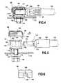
- FIG. 4is a general view similar to FIG. 1 showing a variant device in accordance with the invention
- FIG. 5is a view analogous to FIG. 4 , the elements of the connection device being separate from one another;
- FIG. 6shows the cover of said variant, seen looking along arrow VI in FIG. 5 ;
- FIG. 7shows a variant of the cover in section on VII-VII of FIG. 8 ;
- FIG. 8is a view seen looking along arrow VIII in FIG. 7 ;
- FIG. 9is a view looking along arrow IX in FIG. 7 ;
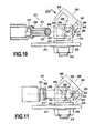
- FIG. 10is an elevation view of another embodiment of the device in accordance with the invention, the plug being shown in section;
- FIGS. 11 to 13show the plug being assembled and locked to its receptacle
- FIG. 14is a detail view looking along arrow XIV of FIG. 10 ;
- FIG. 15is a detail view in perspective of the receptacle and the cover
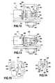
- FIG. 16shows another embodiment of a device in accordance with the invention shown in a manner analogous to FIG. 10 ;
- FIGS. 17 to 19show the device being mounted and locked
- FIG. 20is a detail view seen looking along arrow XX of FIG. 16 .
- connection device 11for making a connection between an electric cable 12 and a conductive structure 13 , here a flat conductor, such as for example a bar forming part of an electrical return circuit in an airplane.
- the connection devicecomprises a connection receptacle 15 of the female type that is fastened to the conductive structure 13 , and a plug 17 of the male type that is connected to one end of said cable 12 .
- electrical cableshould be understood broadly, since it covers any electrical conductor suitable for forming part of a wired electrical network.
- the receptacle 15is made of high conductivity metal, and in this example it includes two threaded extensions 19 passing through respective holes 21 in the conductive structure. Nuts 22 are engaged on the threaded portions so as to provide both mechanical assembly and electrical connection between the receptacle 15 and said conductive structure 13 . Some other number of threaded projections could be provided for fastening purposes.
- the plug 17also made of high conductivity metal, is extended by a bushing 25 having a deformable wall constituting a cylinder for crimping.
- the bushingthus has a blind hole 27 and as a result its wall is thin enough to enable it to be flattened.
- a conductive end of the electric cableis engaged in the blind hole and is held therein by flattening and permanently deforming the wall.
- the bushing 25also has a inspection slot or hole 29 opening out into the blind hole in the vicinity of its inside end. This inspection hole serves to verify that the electric cable 12 is properly inserted into the blind hole 27 before crimping.
- the crimping marks 31can be seen in FIGS. 1 to 3 , by way of illustration.
- the connection receptacle 15includes a bore 33 shaped and dimensioned for receiving said plug 17 with electrical contact.
- the plug 17has two portions 34 a and 34 b of different diameters, and consequently the bore 33 in the receptacle 15 comprises two aligned holes 35 a and 35 b of corresponding different diameters.
- the small-diameter end of the plugincludes a groove 37 .
- the tip 38 of the plugis chamfered to the edges of the groove.
- a locking spring 40is secured to the connection receptacle and includes at least one flexible branch suitable for engaging in the groove 37 when the plug is engaged in the bore 33 .
- the springis of the spring steel wire type.
- the bore 33is a through bore and thus presents an inlet orifice 42 into which the plug is engaged and an outlet orifice 44 of smaller diameter through which the tip 38 of the plug projects, also revealing the groove 37 .
- the length of the plug 17 and the length of the boreare such that the groove 37 lies beyond the outlet orifice 44 of the bore 33 when the plug 17 is engaged therein.
- the spring 40is situated beside the outlet orifice 44 so as to co-operate with the groove 37 of the plug 17 .
- the spring 40is in the form of a substantially U-shaped hairpin, mounted between two projecting elements 48 , 49 of the receptacle.
- the branches of the hairpinhave facing curved portions 50 in the vicinity of the outlet orifice and on either side thereof.
- the receptaclefurther includes an annular sealing gasket 53 surrounding the inside of the outlet orifice 44 . This gasket thus comes to bear against the cylindrical surface of the smaller-diameter portion of the plug.
- the receptacleincludes an inlet gasket 55 fastened externally around the inlet orifice.
- the plughas a shoulder 56 that comes to bear against said inlet gasket 55 .
- the bore 33also contains two annular contact strips 59 that are spaced apart from each other. These contact strips are made of metal having very low resistivity and they are lightly compressed by the larger-diameter portion 34 a of the plug, thereby improving the quality of the electrical contact between the plug and the receptacle.
- connection device 111between an electric cable 112 and a conductive structure 113 forming a flat conductor, namely a bar forming part of an electrical return circuit in an airplane.
- the connection devicecomprises a female type connection receptacle 115 fastened to the structure 113 , and a male type plug 117 connected to an end of the cable 112 .
- the receptacle 115is made of high conductivity metal. It has a single threaded extension 119 passing through a hole 121 in the conductive structure 113 . A nut 122 is engaged on the threaded portion and serves to provide mechanical mounting and electrical connection between the receptacle 115 and the conductive structure 113 . In this example, it should be observed that the entire receptacle 115 may be machined from a cylindrical metal blank, thereby reducing its cost.
- a pin 116is inserted in a housing of the receptacle and occupies a bore 118 formed in the conductive structure 113 , so as to prevent the receptacle from turning.
- the plug 117made entirely out of high conductivity metal, is extended by a bushing 125 having a deformable wall constituting a crimping cylinder, as in the above example.
- This bushingthus includes a blind hole 127 having a thin wall that enables it to be flattened. A conductive end of the electric cable 112 is engaged in said hole before flattening and permanently deforming the wall.
- the bushing 125includes an inspection slot or hole 129 .
- connection receptacle 115includes a bore 133 that is shaped and dimensioned for receiving the plug 117 with electrical contact. Unlike the above embodiment, the portion of the plug 117 that is for engaging in the bore 133 presents a diameter that is constant. However, the bore 133 is a blind hole of corresponding diameter.
- the plughas a groove 137 , but this groove is formed at a distance from the end of the plug 117 .
- the bore 133 in the receptaclethus presents only an inlet orifice 142 into which the plug is engaged.
- the length of the plug and the length of the boreare such that said groove 137 lies outside the inlet orifice 142 when the plug is engaged in the bore in the receptacle.
- this bore 133contains two annular contact strips 159 that are spaced apart from each other. A larger number of them could be provided. These contact strips are made of metal having very low resistivity and they are compressed by the plug when it is engaged in the bore.
- the borealso houses an annular gasket 155 , e.g. an O-ring, placed in a housing inside the bore, in the vicinity of the inlet orifice.
- This gasketmay be overmolded directly in the receptacle. It possesses one or more lips for providing sealing when the plug is engaged.
- the deviceis fitted with a locking spring that comprises a cover 140 shaped to co-operate simultaneously with the groove 137 and with a projecting and annular attachment ring 141 of the receptacle.
- the projecting rimis defined at the end of the receptacle 115 that is remote from its end carrying the threaded extension 119 .
- the coverhas flexible fingers 161 and the ends of these fingers are provided with teeth 143 constituting barbs that co-operate with said projecting rim of the receptacle.
- the cover 140includes a lateral extension 160 , which is relatively flexible in this example, and in which a lateral opening 162 is defined, which opening is shaped and dimensioned so as to co-operate with the groove 137 in the plug. More precisely, in this example, the opening 162 is a notch having a straight mounting portion 163 that is open to one edge of said lateral extension, and a portion having a rounded outline 164 that is retained with clearance in said groove 137 .
- the straight mounting portionleads into the portion having a rounded outline.
- the width of the straight portion 163is slightly smaller than the diameter of the bottom of the groove 137 , while the portion having a rounded outline 164 is slightly greater than the diameter of the bottom of the groove. In this way, the cover is engaged by force on the plug and remains attached thereto, with clearance between the lateral extension and the bottom of the groove.
- the coverincludes a resilient protuberance 166 that bears against the end of the receptacle 115 .
- This resilient protuberancemay be made by a central deformation of the cover or by a tab cut out therefrom.
- the cover 170could be of a different shape.
- the number of flexible fingers 161 acould be smaller than in the above embodiment such that the cover in this example amounts to a kind of three-pronged fork that is extended by the lateral extension 160 a.
- the opening made in the lateral extension 162 amay be an oblong hole 171 of closed outline comprising a circular portion 172 of diameter substantially equal to the diameter of the plug and a circular portion 173 of diameter smaller than the diameter of the plug but greater than the diameter of the bottom of said groove.
- the cover 170is mounted by sliding the plug through the circular portion of greater diameter in the oblong hole 171 until the lateral extension engages in the groove 137 .
- the lateral extensiontilts and locks in the groove by engagement of its smaller-diameter circular portion.
- the coveris held captive.
- the plug 117may be lightened by making a blind hole 175 from its distal end.
- FIGS. 4 to 8presents the advantage of providing sealing that is more reliable, simpler, and less expensive, since it requires only one gasket.
- the locking springmay comprise two portions, a cover of the kind described above and resilient means housed in the bottom of the blind hole of the receptacle in order to push back the plug resiliently and reinforce the locking effect. This then makes it possible to use a cover that is significantly more rigid and thus more robust.
- FIGS. 10 to 15show another embodiment similar to that of FIGS. 4 to 9 . Elements that are analogous are given the same numerical references plus another 100.
- a connection device 211comprising a connection receptacle 215 made of high conductivity metal that is fastened to a conductive structure 213 by a threaded extension 219 and a nut 222 .
- the devicealso comprises a plug 217 of high conductivity metal.
- the receptaclehas a bore 233 for receiving the plug 217 .
- the bore 233is parallel to the conductive structure 213 .
- the plughas a groove 237 formed therein at a distance from its end.
- the groove 237lies outside the inlet orifice 242 of the bore 233 .
- the two annular contact strips 259 of very low conductivity metalthat are arranged inside the bore 233 .
- the devicealso has a locking cover 240 shaped to co-operate simultaneously with the groove 237 and with an attachment rim 241 of the receptacle, constituted in this example by the edge of a hole 245 situated axially in line with the bore 233 , at its end remote from the inlet orifice 242 .
- the cover 240is provided with a finger 246 having a hook 243 (in the form of a chamfered cylinder) that co-operates with the edge of the hole 245 .
- the coverincludes a lateral extension 260 having an opening 262 defined therein that is shaped and dimensioned to co-operate with the groove 237 of said plug. As can be seen in FIG.
- the opening 162is a notch having an outwardly-flared mounting portion 263 that is open to an edge of the lateral extension 260 .
- This mounting portion 264leads to a portion of rounded outline that becomes engaged in the groove 237 .
- the coveris provided with two studs 244 situated internally and facing each other on parallel side faces 248 . These studs are constrained to move in opposite rectilinear parallel grooves 247 formed in the receptacle 215 so that said cover 240 is held captive to said receptacle.
- the plugis provided with an annular gasket 255 situated close to the groove 237 , while the receptacle includes an internal shoulder 256 adjacent to the inlet orifice 242 .
- the hole 245communicates with the bore 233 .
- the end of the plugcarries a cylindrical gasket 257 that becomes compressed at the end of the bore 233 .
- the receptacleneed not have threaded segments 219 and may be welded directly to the conductive structure 213 .
- FIGS. 11 to 13Operation is shown in FIGS. 11 to 13 .
- the cover tilted as shown in FIG. 11the inlet orifice 242 of the bore in the receptacle is disengaged and it is possible to engage the plug 217 in the receptacle.
- the cover 240is tilted while being held as much as possible over the receptacle so that the opening 262 is positioned over the groove 237 of the plug. This is possible only when the plug 217 is pushed fully into the bore 233 of the receptacle and the annular gasket 255 is no longer visible, since it is in contact with the shoulder 256 .
- a positioning inspection window constituted by a hole 258 in the covercomes into register with a colored zone 259 of the receptacle giving the user a visual indication that locking has taken place.
- the devicehas a hole 258 in each of its lateral faces 248 , and the base has two corresponding colored zones 259 .
- FIGS. 16 to 20show yet another embodiment in which analogous structural elements are given the same numerical references increased by 100 once more. These elements are not described again in detail.
- the bore 333 in the receptacle for receiving the plug 317is perpendicular to its mounting plane, i.e. to the conductive structure 313 .
- the axis of the plug 317coincides with the axis of the threaded segment 319 for fastening the receptacle 315 .
- the receptacle 315has two above-mentioned attachment rims 341 situated laterally. These are holes 345 formed in parallel and opposite lateral ribs 370 of the receptacle.
- the coveralso has two parallel fingers 372 having hooks 373 that co-operate respectively with said attachment rims 341 , i.e. the holes 345 , the cover 340 otherwise being substantially identical to that of the above-described embodiment.
- itnaturally includes two studs 344 that are arranged in two parallel rectilinear grooves 347 of the receptacle for holding it captive.
- the coverhas at least one positioning inspection window (a hole 358 ), and the receptacle includes a colored zone 359 with which said window comes into register when the cover is correctly positioned (see FIG. 19 ).
- the mounting shown in FIGS. 17 to 19is comparable with that of the above-described embodiment.
Landscapes
- Connector Housings Or Holding Contact Members (AREA)
- Details Of Connecting Devices For Male And Female Coupling (AREA)
- Coupling Device And Connection With Printed Circuit (AREA)
Abstract
Description
Claims (13)
Applications Claiming Priority (5)
| Application Number | Priority Date | Filing Date | Title |
|---|---|---|---|
| FR0855657 | 2008-08-21 | ||
| FR0855657AFR2935202B1 (en) | 2008-08-21 | 2008-08-21 | DEVICE FOR CONNECTION BETWEEN AN ELECTRICAL CABLE AND A CONDUCTIVE STRUCTURE, IN PARTICULAR FOR A CURRENT RETURN CIRCUIT |
| FR0951196AFR2935200B1 (en) | 2008-08-21 | 2009-02-25 | DEVICE FOR CONNECTION BETWEEN AN ELECTRICAL CABLE AND A CONDUCTIVE STRUCTURE, IN PARTICULAR FOR A CURRENT RETURN CIRCUIT |
| FR0951196 | 2009-02-25 | ||
| PCT/FR2009/051602WO2010020733A1 (en) | 2008-08-21 | 2009-08-19 | Connection device between an electrical cable and a conducting structure, especially for a current return circuit |
Publications (2)
| Publication Number | Publication Date |
|---|---|
| US20110237104A1 US20110237104A1 (en) | 2011-09-29 |
| US8562371B2true US8562371B2 (en) | 2013-10-22 |
Family
ID=40469967
Family Applications (1)
| Application Number | Title | Priority Date | Filing Date |
|---|---|---|---|
| US13/060,190ActiveUS8562371B2 (en) | 2008-08-21 | 2009-08-19 | Connection device between an electrical cable and a conducting structure, especially for a current return circuit |
Country Status (7)
| Country | Link |
|---|---|
| US (1) | US8562371B2 (en) |
| EP (1) | EP2324534B1 (en) |
| CN (1) | CN102132459B (en) |
| BR (1) | BRPI0917817B1 (en) |
| CA (1) | CA2734695C (en) |
| FR (2) | FR2935202B1 (en) |
| WO (1) | WO2010020733A1 (en) |
Cited By (5)
| Publication number | Priority date | Publication date | Assignee | Title |
|---|---|---|---|---|
| US8814574B2 (en)* | 2012-12-31 | 2014-08-26 | Suunto Oy | Male end of a telemetric transceiver |
| US9502801B2 (en)* | 2015-04-02 | 2016-11-22 | Makita Corporation | Electric apparatus having a plate-shaped male terminal with a level difference in its thickness direction |
| US10084248B2 (en) | 2015-07-16 | 2018-09-25 | Safran Electrical & Power | Freely translatable electrical connection device having protection against damage from foreign bodies |
| US10224698B1 (en)* | 2018-02-01 | 2019-03-05 | Etco, Inc. | Ignition wire spark plug connector |
| US10398377B2 (en)* | 2015-09-04 | 2019-09-03 | Japan Science And Technology Agency | Connector substrate, sensor system, and wearable sensor system |
Families Citing this family (19)
| Publication number | Priority date | Publication date | Assignee | Title |
|---|---|---|---|---|
| DE202008014409U1 (en)* | 2008-10-29 | 2009-01-22 | Rosenberger Hochfrequenztechnik Gmbh & Co. Kg | HF right-angle connector |
| US8777647B2 (en)* | 2010-12-07 | 2014-07-15 | Delta Systems, Inc. | Connection system and method |
| CN102157819A (en)* | 2010-12-28 | 2011-08-17 | 电光防爆科技(上海)有限公司 | Mine-used anti-loosening wire connection device |
| US8851923B2 (en) | 2012-08-08 | 2014-10-07 | Emerson Electric Co. | Hermetically sealed terminal pins with holes for connecting to wires |
| AT513865B1 (en)* | 2013-02-01 | 2014-12-15 | Hirtenberger Automotive Safety | actuator |
| EP3142207B1 (en)* | 2015-09-11 | 2018-06-06 | NKT HV Cables GmbH | Fastening device for a cable termination and arrangement comprising fastening device and cable termination |
| DE102015016926A1 (en)* | 2015-12-24 | 2017-06-29 | Audi Ag | Electrical connection element |
| DE202016102669U1 (en)* | 2016-05-19 | 2017-08-22 | Würth Elektronik eiSos Gmbh & Co. KG | Contacting device for electrical energy transmission to a printed circuit board |
| CN111725679B (en)* | 2016-12-12 | 2021-12-10 | 上海电巴新能源科技有限公司 | Electrical connection device |
| CN107317296B (en)* | 2017-08-09 | 2023-10-31 | 上海胜华电气股份有限公司 | Fireproof and watertight pre-branched magnesium oxide cable and its installation method |
| CN109687212A (en)* | 2018-11-01 | 2019-04-26 | 深圳金信诺光电技术有限公司 | A kind of connector of 90 ° of outlets |
| CN112117588A (en)* | 2020-09-29 | 2020-12-22 | 宣城立讯精密工业有限公司 | A sealing ring and connector |
| CN113363739B (en)* | 2021-05-25 | 2022-01-21 | 上海沪安电缆(无锡)有限公司 | Connector for fire-resistant insulated wires and cables and use method thereof |
| WO2024218693A1 (en)* | 2023-04-17 | 2024-10-24 | Molex, Llc | Power connector and method of assembly |
| USD1069716S1 (en) | 2023-05-05 | 2025-04-08 | Molex, Llc | Connector |
| USD1051061S1 (en) | 2023-05-05 | 2024-11-12 | Molex, Llc | Connector |
| USD1065091S1 (en) | 2023-05-05 | 2025-03-04 | Molex, Llc | Connector |
| USD1054992S1 (en) | 2023-05-05 | 2024-12-24 | Molex, Llc | Connector |
| WO2025196645A1 (en)* | 2024-03-18 | 2025-09-25 | Molex, Llc | Power connector and method of assembly |
Citations (23)
| Publication number | Priority date | Publication date | Assignee | Title |
|---|---|---|---|---|
| US2845291A (en)* | 1955-01-25 | 1958-07-29 | Gen Motors Corp | Retaining clip and assembly |
| US4883397A (en)* | 1988-02-24 | 1989-11-28 | Rapid S.A. | U-shaped fastening clip device with resilient tongue member |
| US4934366A (en)* | 1988-09-01 | 1990-06-19 | Siemens-Pacesetter, Inc. | Feedthrough connector for implantable medical device |
| EP0422372A2 (en) | 1989-10-10 | 1991-04-17 | Robert Bosch Gmbh | Ignition distributor rotor for combustion engines |
| US5499448A (en)* | 1993-07-19 | 1996-03-19 | Aerospace Societe Nationale Industrielle | Process for connecting an electric cable to an end member |
| US5518332A (en)* | 1993-11-30 | 1996-05-21 | Nippon Cable System Inc. | End plate with clip |
| DE19714511A1 (en) | 1996-04-08 | 1997-11-06 | Nissan Motor | Terminal lug connection structure of storage battery e.g. for electric vehicle |
| US5704100A (en)* | 1996-03-01 | 1998-01-06 | Federal-Hoffman, Inc. | Retaining clip system |
| US6056577A (en)* | 1997-05-29 | 2000-05-02 | Air-Lb Gmbh | Electrical connector with interlock |
| US6234706B1 (en)* | 1996-09-18 | 2001-05-22 | Siemens Aktiengesellschaft | Locking device for a rectilinearly displaceable component |
| EP1253671A2 (en) | 2001-04-25 | 2002-10-30 | Harting Automotive GmbH & Co. KG | Battery terminal and battery |
| US6490947B2 (en)* | 2000-06-23 | 2002-12-10 | Arnd Burger | Spring for attaching cable end fitting to bracket |
| DE10211634A1 (en) | 2002-03-15 | 2003-10-09 | Gessmann Gmbh & Co | Electrical pluggable connector, has first and second connection elements, the first having an annular groove into which latches spring tongues of the second |
| US20040038596A1 (en)* | 2000-04-15 | 2004-02-26 | Mario Bartholoma | Plug-in connector with a bushing |
| US6835084B2 (en)* | 2002-02-15 | 2004-12-28 | Bal Seal Engineering Co., Inc. | Medically implantable electrical connector with constant conductivity |
| US6854946B2 (en)* | 2002-08-22 | 2005-02-15 | Allegiance Corporation | Flexible retainer clip |
| US20070184700A1 (en) | 2006-02-03 | 2007-08-09 | Watlow Electric Manufacturing Company | High voltage heater termination |
| US7309247B1 (en)* | 2006-05-23 | 2007-12-18 | Micro-Coax | Cable interconnect |
| US7331813B2 (en)* | 2004-06-09 | 2008-02-19 | Nitto Kohki Co., Ltd. | Plug-socket assembly |
| US7568855B2 (en)* | 2005-08-08 | 2009-08-04 | Demag Cranes & Components Gmbh | Arrangement for axial securing of grooved bolt |
| US7914347B2 (en)* | 2009-04-30 | 2011-03-29 | Corning Gilbert Inc. | Low resistance connector for printed circuit board |
| US7999202B2 (en)* | 2008-04-14 | 2011-08-16 | Mitsubishi Electric Corporation | Contact |
| US8221150B2 (en)* | 2008-06-25 | 2012-07-17 | Societe D'exploitation Des Procedes Marechal | Device for secure electrical connection |
Family Cites Families (6)
| Publication number | Priority date | Publication date | Assignee | Title |
|---|---|---|---|---|
| US2112680A (en)* | 1934-10-25 | 1938-03-29 | Gen Electric | Electric cord terminal |
| JPS5540202U (en)* | 1978-09-07 | 1980-03-14 | ||
| US4671591A (en)* | 1985-07-15 | 1987-06-09 | Physio-Control Corporation | Electrical connector |
| US4642859A (en)* | 1986-06-23 | 1987-02-17 | Chrysler Motors Corporation | Retaining clip |
| FR2756879A1 (en)* | 1996-12-06 | 1998-06-12 | Adwest Oci Sa | Mounting for cable sheath in motor vehicle |
| DE202004015917U1 (en)* | 2004-10-13 | 2005-01-20 | Virchow, Florian | Contacting element for electrically contacting components |
- 2008
- 2008-08-21FRFR0855657Apatent/FR2935202B1/ennot_activeExpired - Fee Related
- 2009
- 2009-02-25FRFR0951196Apatent/FR2935200B1/ennot_activeExpired - Fee Related
- 2009-08-19CNCN200980132541.7Apatent/CN102132459B/enactiveActive
- 2009-08-19USUS13/060,190patent/US8562371B2/enactiveActive
- 2009-08-19WOPCT/FR2009/051602patent/WO2010020733A1/enactiveApplication Filing
- 2009-08-19BRBRPI0917817-1Apatent/BRPI0917817B1/ennot_activeIP Right Cessation
- 2009-08-19CACA2734695Apatent/CA2734695C/ennot_activeExpired - Fee Related
- 2009-08-19EPEP09740472.7Apatent/EP2324534B1/enactiveActive
Patent Citations (26)
| Publication number | Priority date | Publication date | Assignee | Title |
|---|---|---|---|---|
| US2845291A (en)* | 1955-01-25 | 1958-07-29 | Gen Motors Corp | Retaining clip and assembly |
| US4883397A (en)* | 1988-02-24 | 1989-11-28 | Rapid S.A. | U-shaped fastening clip device with resilient tongue member |
| US4934366A (en)* | 1988-09-01 | 1990-06-19 | Siemens-Pacesetter, Inc. | Feedthrough connector for implantable medical device |
| EP0422372A2 (en) | 1989-10-10 | 1991-04-17 | Robert Bosch Gmbh | Ignition distributor rotor for combustion engines |
| US5499448A (en)* | 1993-07-19 | 1996-03-19 | Aerospace Societe Nationale Industrielle | Process for connecting an electric cable to an end member |
| US5518332A (en)* | 1993-11-30 | 1996-05-21 | Nippon Cable System Inc. | End plate with clip |
| US5704100A (en)* | 1996-03-01 | 1998-01-06 | Federal-Hoffman, Inc. | Retaining clip system |
| DE19714511A1 (en) | 1996-04-08 | 1997-11-06 | Nissan Motor | Terminal lug connection structure of storage battery e.g. for electric vehicle |
| US6030722A (en) | 1996-04-08 | 2000-02-29 | Yazaki Corporation | Storage battery terminal structure |
| US6234706B1 (en)* | 1996-09-18 | 2001-05-22 | Siemens Aktiengesellschaft | Locking device for a rectilinearly displaceable component |
| US6056577A (en)* | 1997-05-29 | 2000-05-02 | Air-Lb Gmbh | Electrical connector with interlock |
| US20040038596A1 (en)* | 2000-04-15 | 2004-02-26 | Mario Bartholoma | Plug-in connector with a bushing |
| US6490947B2 (en)* | 2000-06-23 | 2002-12-10 | Arnd Burger | Spring for attaching cable end fitting to bracket |
| US20020160665A1 (en) | 2001-04-25 | 2002-10-31 | Harting Automotive Gmbh & Co. Kg | Battery clamp and battery |
| EP1253671A2 (en) | 2001-04-25 | 2002-10-30 | Harting Automotive GmbH & Co. KG | Battery terminal and battery |
| US6835084B2 (en)* | 2002-02-15 | 2004-12-28 | Bal Seal Engineering Co., Inc. | Medically implantable electrical connector with constant conductivity |
| DE10211634A1 (en) | 2002-03-15 | 2003-10-09 | Gessmann Gmbh & Co | Electrical pluggable connector, has first and second connection elements, the first having an annular groove into which latches spring tongues of the second |
| US6854946B2 (en)* | 2002-08-22 | 2005-02-15 | Allegiance Corporation | Flexible retainer clip |
| US7331813B2 (en)* | 2004-06-09 | 2008-02-19 | Nitto Kohki Co., Ltd. | Plug-socket assembly |
| US7568855B2 (en)* | 2005-08-08 | 2009-08-04 | Demag Cranes & Components Gmbh | Arrangement for axial securing of grooved bolt |
| US20070184700A1 (en) | 2006-02-03 | 2007-08-09 | Watlow Electric Manufacturing Company | High voltage heater termination |
| US7581958B2 (en)* | 2006-02-03 | 2009-09-01 | Watlow Electric Manufacturing Company | High voltage heater termination |
| US7309247B1 (en)* | 2006-05-23 | 2007-12-18 | Micro-Coax | Cable interconnect |
| US7999202B2 (en)* | 2008-04-14 | 2011-08-16 | Mitsubishi Electric Corporation | Contact |
| US8221150B2 (en)* | 2008-06-25 | 2012-07-17 | Societe D'exploitation Des Procedes Marechal | Device for secure electrical connection |
| US7914347B2 (en)* | 2009-04-30 | 2011-03-29 | Corning Gilbert Inc. | Low resistance connector for printed circuit board |
Non-Patent Citations (1)
| Title |
|---|
| International Search Report Issued Dec. 2, 2009 in PCT/FR09/051602 filed Aug. 19, 2009. |
Cited By (5)
| Publication number | Priority date | Publication date | Assignee | Title |
|---|---|---|---|---|
| US8814574B2 (en)* | 2012-12-31 | 2014-08-26 | Suunto Oy | Male end of a telemetric transceiver |
| US9502801B2 (en)* | 2015-04-02 | 2016-11-22 | Makita Corporation | Electric apparatus having a plate-shaped male terminal with a level difference in its thickness direction |
| US10084248B2 (en) | 2015-07-16 | 2018-09-25 | Safran Electrical & Power | Freely translatable electrical connection device having protection against damage from foreign bodies |
| US10398377B2 (en)* | 2015-09-04 | 2019-09-03 | Japan Science And Technology Agency | Connector substrate, sensor system, and wearable sensor system |
| US10224698B1 (en)* | 2018-02-01 | 2019-03-05 | Etco, Inc. | Ignition wire spark plug connector |
Also Published As
| Publication number | Publication date |
|---|---|
| EP2324534A1 (en) | 2011-05-25 |
| BRPI0917817B1 (en) | 2020-05-12 |
| EP2324534B1 (en) | 2018-10-03 |
| FR2935202B1 (en) | 2010-10-22 |
| US20110237104A1 (en) | 2011-09-29 |
| CA2734695A1 (en) | 2010-02-25 |
| FR2935200B1 (en) | 2010-10-22 |
| CN102132459A (en) | 2011-07-20 |
| FR2935200A1 (en) | 2010-02-26 |
| BRPI0917817A2 (en) | 2015-11-24 |
| WO2010020733A1 (en) | 2010-02-25 |
| CN102132459B (en) | 2014-11-19 |
| CA2734695C (en) | 2016-05-17 |
| FR2935202A1 (en) | 2010-02-26 |
Similar Documents
| Publication | Publication Date | Title |
|---|---|---|
| US8562371B2 (en) | Connection device between an electrical cable and a conducting structure, especially for a current return circuit | |
| EP3021424B1 (en) | Electrical connector assembly comprising a grounding link and corresponding method of connection | |
| US20230383417A1 (en) | Test station assemblies for monitoring cathodic protection of structures and related methods | |
| US9077114B2 (en) | Quick connect power connector | |
| US10122117B2 (en) | Quick connect power connector system | |
| EP2221927A2 (en) | Sealed and grounded electrical connector and sealed and grounded electrical connector assembly | |
| EP2688153B1 (en) | Electrical connector having grounding mechanism | |
| US5571031A (en) | Watthour meter mounting apparatus with improved electrical connections | |
| US5577933A (en) | Watthour meter mounting apparatus with safety shield | |
| US8858264B2 (en) | Electrical terminal retainer and receptacle assembly | |
| US9225116B2 (en) | Quick connect power connector isolating system | |
| US20100087083A1 (en) | Pe connection for plug connectors | |
| CA3087209A1 (en) | Pin and sleeve device with contact carrier for capturing set screws | |
| US20100130042A1 (en) | Connector socket, a connector plug, and an appliance fitted with a connector | |
| US20130109220A1 (en) | Attachable plug-type connector | |
| US20190107563A1 (en) | Electrical connector having a sacrificial cap and integrated test point | |
| US20100243835A1 (en) | Position assurance assembly for an electrical connector | |
| US20030224658A1 (en) | Electrical connector | |
| US9033736B2 (en) | Electrical connector with maximized circuit-to-circuit isolation distance | |
| US20130344749A1 (en) | RF Connector with Push-On Connection | |
| US20130084757A1 (en) | Electrical connector system and method for making the same | |
| US6123549A (en) | High integrity electrical connector | |
| CN112074994B (en) | Electrical connector with staggered contact carrier | |
| CA3209157A1 (en) | Test station assemblies for monitoring cathodic protection of structures and related methods | |
| HK1223456B (en) | Electrical connector assembly comprising a grounding link and corresponding method of connection |
Legal Events
| Date | Code | Title | Description |
|---|---|---|---|
| AS | Assignment | Owner name:LABINAL, FRANCE Free format text:ASSIGNMENT OF ASSIGNORS INTEREST;ASSIGNORS:BIESSE, JEAN-LUC;LAURENT, DIDIER;ROQUES, SERGE;REEL/FRAME:026414/0900 Effective date:20110509 | |
| STCF | Information on status: patent grant | Free format text:PATENTED CASE | |
| FPAY | Fee payment | Year of fee payment:4 | |
| AS | Assignment | Owner name:SAFRAN ELECTRICAL & POWER, FRANCE Free format text:CHANGE OF NAME;ASSIGNOR:LABINAL POWER SYSTEMS;REEL/FRAME:046678/0487 Effective date:20160503 Owner name:LABINAL POWER SYSTEMS, FRANCE Free format text:CHANGE OF NAME;ASSIGNOR:LABINAL;REEL/FRAME:047111/0012 Effective date:20140102 | |
| MAFP | Maintenance fee payment | Free format text:PAYMENT OF MAINTENANCE FEE, 8TH YEAR, LARGE ENTITY (ORIGINAL EVENT CODE: M1552); ENTITY STATUS OF PATENT OWNER: LARGE ENTITY Year of fee payment:8 | |
| MAFP | Maintenance fee payment | Free format text:PAYMENT OF MAINTENANCE FEE, 12TH YEAR, LARGE ENTITY (ORIGINAL EVENT CODE: M1553); ENTITY STATUS OF PATENT OWNER: LARGE ENTITY Year of fee payment:12 |