US8562365B2 - Laminous multi-polymeric high amperage over-molded connector assembly for plug-in hybrid electric vehicle charging - Google Patents
Laminous multi-polymeric high amperage over-molded connector assembly for plug-in hybrid electric vehicle chargingDownload PDFInfo
- Publication number
- US8562365B2 US8562365B2US13/211,867US201113211867AUS8562365B2US 8562365 B2US8562365 B2US 8562365B2US 201113211867 AUS201113211867 AUS 201113211867AUS 8562365 B2US8562365 B2US 8562365B2
- Authority
- US
- United States
- Prior art keywords
- connector
- connector body
- electrical
- potting compound
- premold
- Prior art date
- Legal status (The legal status is an assumption and is not a legal conclusion. Google has not performed a legal analysis and makes no representation as to the accuracy of the status listed.)
- Active
Links
Images


Classifications
- H—ELECTRICITY
- H01—ELECTRIC ELEMENTS
- H01R—ELECTRICALLY-CONDUCTIVE CONNECTIONS; STRUCTURAL ASSOCIATIONS OF A PLURALITY OF MUTUALLY-INSULATED ELECTRICAL CONNECTING ELEMENTS; COUPLING DEVICES; CURRENT COLLECTORS
- H01R13/00—Details of coupling devices of the kinds covered by groups H01R12/70 or H01R24/00 - H01R33/00
- H01R13/62—Means for facilitating engagement or disengagement of coupling parts or for holding them in engagement
- H01R13/627—Snap or like fastening
- H01R13/6275—Latching arms not integral with the housing
- B—PERFORMING OPERATIONS; TRANSPORTING
- B60—VEHICLES IN GENERAL
- B60L—PROPULSION OF ELECTRICALLY-PROPELLED VEHICLES; SUPPLYING ELECTRIC POWER FOR AUXILIARY EQUIPMENT OF ELECTRICALLY-PROPELLED VEHICLES; ELECTRODYNAMIC BRAKE SYSTEMS FOR VEHICLES IN GENERAL; MAGNETIC SUSPENSION OR LEVITATION FOR VEHICLES; MONITORING OPERATING VARIABLES OF ELECTRICALLY-PROPELLED VEHICLES; ELECTRIC SAFETY DEVICES FOR ELECTRICALLY-PROPELLED VEHICLES
- B60L53/00—Methods of charging batteries, specially adapted for electric vehicles; Charging stations or on-board charging equipment therefor; Exchange of energy storage elements in electric vehicles
- B60L53/10—Methods of charging batteries, specially adapted for electric vehicles; Charging stations or on-board charging equipment therefor; Exchange of energy storage elements in electric vehicles characterised by the energy transfer between the charging station and the vehicle
- B60L53/14—Conductive energy transfer
- B60L53/16—Connectors, e.g. plugs or sockets, specially adapted for charging electric vehicles
- H—ELECTRICITY
- H01—ELECTRIC ELEMENTS
- H01R—ELECTRICALLY-CONDUCTIVE CONNECTIONS; STRUCTURAL ASSOCIATIONS OF A PLURALITY OF MUTUALLY-INSULATED ELECTRICAL CONNECTING ELEMENTS; COUPLING DEVICES; CURRENT COLLECTORS
- H01R13/00—Details of coupling devices of the kinds covered by groups H01R12/70 or H01R24/00 - H01R33/00
- H01R13/46—Bases; Cases
- H01R13/502—Bases; Cases composed of different pieces
- H01R13/504—Bases; Cases composed of different pieces different pieces being moulded, cemented, welded, e.g. ultrasonic, or swaged together
- B—PERFORMING OPERATIONS; TRANSPORTING
- B60—VEHICLES IN GENERAL
- B60L—PROPULSION OF ELECTRICALLY-PROPELLED VEHICLES; SUPPLYING ELECTRIC POWER FOR AUXILIARY EQUIPMENT OF ELECTRICALLY-PROPELLED VEHICLES; ELECTRODYNAMIC BRAKE SYSTEMS FOR VEHICLES IN GENERAL; MAGNETIC SUSPENSION OR LEVITATION FOR VEHICLES; MONITORING OPERATING VARIABLES OF ELECTRICALLY-PROPELLED VEHICLES; ELECTRIC SAFETY DEVICES FOR ELECTRICALLY-PROPELLED VEHICLES
- B60L2240/00—Control parameters of input or output; Target parameters
- B60L2240/60—Navigation input
- B60L2240/66—Ambient conditions
- B60L2240/667—Precipitation
- B—PERFORMING OPERATIONS; TRANSPORTING
- B60—VEHICLES IN GENERAL
- B60L—PROPULSION OF ELECTRICALLY-PROPELLED VEHICLES; SUPPLYING ELECTRIC POWER FOR AUXILIARY EQUIPMENT OF ELECTRICALLY-PROPELLED VEHICLES; ELECTRODYNAMIC BRAKE SYSTEMS FOR VEHICLES IN GENERAL; MAGNETIC SUSPENSION OR LEVITATION FOR VEHICLES; MONITORING OPERATING VARIABLES OF ELECTRICALLY-PROPELLED VEHICLES; ELECTRIC SAFETY DEVICES FOR ELECTRICALLY-PROPELLED VEHICLES
- B60L2270/00—Problem solutions or means not otherwise provided for
- B60L2270/30—Preventing theft during charging
- B60L2270/32—Preventing theft during charging of electricity
- B—PERFORMING OPERATIONS; TRANSPORTING
- B60—VEHICLES IN GENERAL
- B60L—PROPULSION OF ELECTRICALLY-PROPELLED VEHICLES; SUPPLYING ELECTRIC POWER FOR AUXILIARY EQUIPMENT OF ELECTRICALLY-PROPELLED VEHICLES; ELECTRODYNAMIC BRAKE SYSTEMS FOR VEHICLES IN GENERAL; MAGNETIC SUSPENSION OR LEVITATION FOR VEHICLES; MONITORING OPERATING VARIABLES OF ELECTRICALLY-PROPELLED VEHICLES; ELECTRIC SAFETY DEVICES FOR ELECTRICALLY-PROPELLED VEHICLES
- B60L2270/00—Problem solutions or means not otherwise provided for
- B60L2270/30—Preventing theft during charging
- B60L2270/34—Preventing theft during charging of parts
- H—ELECTRICITY
- H01—ELECTRIC ELEMENTS
- H01R—ELECTRICALLY-CONDUCTIVE CONNECTIONS; STRUCTURAL ASSOCIATIONS OF A PLURALITY OF MUTUALLY-INSULATED ELECTRICAL CONNECTING ELEMENTS; COUPLING DEVICES; CURRENT COLLECTORS
- H01R13/00—Details of coupling devices of the kinds covered by groups H01R12/70 or H01R24/00 - H01R33/00
- H01R13/46—Bases; Cases
- H01R13/52—Dustproof, splashproof, drip-proof, waterproof, or flameproof cases
- H01R13/5227—Dustproof, splashproof, drip-proof, waterproof, or flameproof cases with evacuation of penetrating liquids
- H—ELECTRICITY
- H01—ELECTRIC ELEMENTS
- H01R—ELECTRICALLY-CONDUCTIVE CONNECTIONS; STRUCTURAL ASSOCIATIONS OF A PLURALITY OF MUTUALLY-INSULATED ELECTRICAL CONNECTING ELEMENTS; COUPLING DEVICES; CURRENT COLLECTORS
- H01R13/00—Details of coupling devices of the kinds covered by groups H01R12/70 or H01R24/00 - H01R33/00
- H01R13/66—Structural association with built-in electrical component
- H01R13/717—Structural association with built-in electrical component with built-in light source
- Y—GENERAL TAGGING OF NEW TECHNOLOGICAL DEVELOPMENTS; GENERAL TAGGING OF CROSS-SECTIONAL TECHNOLOGIES SPANNING OVER SEVERAL SECTIONS OF THE IPC; TECHNICAL SUBJECTS COVERED BY FORMER USPC CROSS-REFERENCE ART COLLECTIONS [XRACs] AND DIGESTS
- Y02—TECHNOLOGIES OR APPLICATIONS FOR MITIGATION OR ADAPTATION AGAINST CLIMATE CHANGE
- Y02T—CLIMATE CHANGE MITIGATION TECHNOLOGIES RELATED TO TRANSPORTATION
- Y02T10/00—Road transport of goods or passengers
- Y02T10/60—Other road transportation technologies with climate change mitigation effect
- Y02T10/70—Energy storage systems for electromobility, e.g. batteries
- Y—GENERAL TAGGING OF NEW TECHNOLOGICAL DEVELOPMENTS; GENERAL TAGGING OF CROSS-SECTIONAL TECHNOLOGIES SPANNING OVER SEVERAL SECTIONS OF THE IPC; TECHNICAL SUBJECTS COVERED BY FORMER USPC CROSS-REFERENCE ART COLLECTIONS [XRACs] AND DIGESTS
- Y02—TECHNOLOGIES OR APPLICATIONS FOR MITIGATION OR ADAPTATION AGAINST CLIMATE CHANGE
- Y02T—CLIMATE CHANGE MITIGATION TECHNOLOGIES RELATED TO TRANSPORTATION
- Y02T10/00—Road transport of goods or passengers
- Y02T10/60—Other road transportation technologies with climate change mitigation effect
- Y02T10/7072—Electromobility specific charging systems or methods for batteries, ultracapacitors, supercapacitors or double-layer capacitors
- Y—GENERAL TAGGING OF NEW TECHNOLOGICAL DEVELOPMENTS; GENERAL TAGGING OF CROSS-SECTIONAL TECHNOLOGIES SPANNING OVER SEVERAL SECTIONS OF THE IPC; TECHNICAL SUBJECTS COVERED BY FORMER USPC CROSS-REFERENCE ART COLLECTIONS [XRACs] AND DIGESTS
- Y02—TECHNOLOGIES OR APPLICATIONS FOR MITIGATION OR ADAPTATION AGAINST CLIMATE CHANGE
- Y02T—CLIMATE CHANGE MITIGATION TECHNOLOGIES RELATED TO TRANSPORTATION
- Y02T10/00—Road transport of goods or passengers
- Y02T10/60—Other road transportation technologies with climate change mitigation effect
- Y02T10/72—Electric energy management in electromobility
- Y—GENERAL TAGGING OF NEW TECHNOLOGICAL DEVELOPMENTS; GENERAL TAGGING OF CROSS-SECTIONAL TECHNOLOGIES SPANNING OVER SEVERAL SECTIONS OF THE IPC; TECHNICAL SUBJECTS COVERED BY FORMER USPC CROSS-REFERENCE ART COLLECTIONS [XRACs] AND DIGESTS
- Y02—TECHNOLOGIES OR APPLICATIONS FOR MITIGATION OR ADAPTATION AGAINST CLIMATE CHANGE
- Y02T—CLIMATE CHANGE MITIGATION TECHNOLOGIES RELATED TO TRANSPORTATION
- Y02T90/00—Enabling technologies or technologies with a potential or indirect contribution to GHG emissions mitigation
- Y02T90/10—Technologies relating to charging of electric vehicles
- Y02T90/14—Plug-in electric vehicles
- Y—GENERAL TAGGING OF NEW TECHNOLOGICAL DEVELOPMENTS; GENERAL TAGGING OF CROSS-SECTIONAL TECHNOLOGIES SPANNING OVER SEVERAL SECTIONS OF THE IPC; TECHNICAL SUBJECTS COVERED BY FORMER USPC CROSS-REFERENCE ART COLLECTIONS [XRACs] AND DIGESTS
- Y02—TECHNOLOGIES OR APPLICATIONS FOR MITIGATION OR ADAPTATION AGAINST CLIMATE CHANGE
- Y02T—CLIMATE CHANGE MITIGATION TECHNOLOGIES RELATED TO TRANSPORTATION
- Y02T90/00—Enabling technologies or technologies with a potential or indirect contribution to GHG emissions mitigation
- Y02T90/10—Technologies relating to charging of electric vehicles
- Y02T90/16—Information or communication technologies improving the operation of electric vehicles
- Y—GENERAL TAGGING OF NEW TECHNOLOGICAL DEVELOPMENTS; GENERAL TAGGING OF CROSS-SECTIONAL TECHNOLOGIES SPANNING OVER SEVERAL SECTIONS OF THE IPC; TECHNICAL SUBJECTS COVERED BY FORMER USPC CROSS-REFERENCE ART COLLECTIONS [XRACs] AND DIGESTS
- Y10—TECHNICAL SUBJECTS COVERED BY FORMER USPC
- Y10T—TECHNICAL SUBJECTS COVERED BY FORMER US CLASSIFICATION
- Y10T29/00—Metal working
- Y10T29/49—Method of mechanical manufacture
- Y10T29/49002—Electrical device making
- Y10T29/49117—Conductor or circuit manufacturing
- Y10T29/49174—Assembling terminal to elongated conductor
- Y10T29/49176—Assembling terminal to elongated conductor with molding of electrically insulating material
Definitions
- the present inventionis directed to an electrical connector for supplying power to an electric vehicle and more particularly to such a connector having improved resistance to water in the environment and improved user-friendliness.
- Electric vehiclesare increasingly receiving attention. These include plug-in hybrid vehicles such as the Chevrolet Volt and purely electric vehicles such as the Nissan Leaf.
- the front of the connectorhas a standardized shape and five pins in a standardized layout, so that all connectors work with all electric vehicles.
- the five pinsare two AC power pins, a ground pin, a proximity detection pin and a control pilot pin.
- the manufacturer of each connectorhas some discretion.
- Known connectorstypically use spring latches to secure the connector to the vehicle during charging.
- known connectorsare typically manufactured from multiple parts. As a consequence, they can be expensive to manufacture and prone to failure.
- the present inventionis directed to a connector having at least one of the following features.
- the spring latchis not sealed; instead, the connector body has holes allowing water entering the spring latch mechanism to drain harmlessly out of the connector.
- a forward-facing LED or other light sourceacts as a flashlight. Once the connector is connected, the forward-facing LED is switched off, and a rear-facing LED or other light source is switched on to confirm that the connector is connected and capable of charging the vehicle.
- the connectoris produced by overmolding.
- the connectorcan be produced in a three-layer configuration, with potting material, a premold, and a one-piece overmold.
- Each of the layerscan be formed of a different material that gives it the properties needed for its location in the connector.
- the modular designallows for faster product updates and a common platform for product diversification.
- the problem being solved by this inventionis offering the EV (electric vehicle) market space (such as Original Equipment Manufacturers (OEM) and Electric Vehicle Supply Equipment (EVSE) manufacturers) a ruggedized and integrated overmolded SAE J1772 connector and cable assembly solution that offers reduced life-cycle costs and improved product reliability, and that also reduces the risks of tampering and vandalism associated with mechanical locking features and hardware (such as TorxTM Screws).
- This over-molded solutionoffers exceptional environmental protection from the extreme environmental elements which may include: water, ice, dust, ultra-violet rays, oils and automotive fluids.
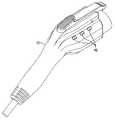
- FIGS. 1-8are various views of the connector according to the preferred embodiment and of various components thereof.
- FIGS. 9A-21are views showing steps in the production of the connector of FIGS. 1-8 .
- the connector 100includes a connector front piece 102 with a plurality of pins 104 , 106 , 108 , 110 , 112 .
- the connector front piece 102 and the pins 104 - 112follow the standard SAE J1772.
- the pins 104 - 112are electrically connected to a cable 114 at a location which is sealed inside of the connector front piece 102 with potting 116 .
- a connector body 118is formed over the connector front piece 102 and the cable 114 by a premold 120 and an overmold 122 .
- the premold 120 and the overmold 122are formed with ridges 124 , 126 to increase the strength of the connector body 118 .
- the connector bodyhas a latch area 128 with a spring latch 130 having a pin 132 and a spring 134 .
- a first LED or other light 136can be provided to act as a flashlight, so that the user can use the connector at night in situations of poor lighting.
- a second LED or other light 138can be provided on the back to indicate when the proper electrical connection between the connector and the vehicle is achieved, at which time the first LED is switched off.
- Circuitry 140such as a printed circuit (PC) board to be described below, is provided for controlling the LED's.
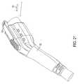
- the latch area 128does not have to be sealed against water. Instead, water entering the latch area 128 exits through holes 142 . As shown, there are three holes 142 on either side of the latch area 128 , extending through the overmold 122 and into the latch area 128 . The holes 142 are open to the latch area 128 at a bottom surface 144 of the latch area 128 so that there will be no places for the water to accumulate. However, any suitable number and configuration of holes can be used instead of, or in addition to, the holes shown.
- the holes 142are positioned relative to the bottom surface 144 of the latch area 128 so that all of the water drains out of the latch area 128 rather than forming puddles below the holes 142 .
- the holes 142are shown as extending horizontally to facilitate overmolding.
- the left and right components of the mold used in the overmoldingcan have projections corresponding to the holes 142 and thus form the holes 142 . After the overmolding process, the left and right components are pulled off in a horizontal direction to pull the projections out of the holes 142 thus formed.
- the configuration of the holes 142can be varied in accordance with various manufacturing techniques. For example, in different manufacturing techniques, the holes 142 could slope downwardly from the latch area 128 or even extend vertically downwardly from the latch area 128 .
- holes 142can be formed in any other suitable manner, e.g., by drilling.
- the latch area 128could have a bottom surface 144 that is flat or that is crowned to urge water out through the holes 142 .
- the holes 142are shown as elongated, they could have any suitable shape, e.g., round.
- the preferred embodimentprovides an overmolded, ruggedized, and robust high-amperage SAE J1772 connector assembly.
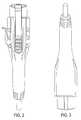
- the production of the preferred embodimentbegins with an insert molded SAE J1772 10 amp through 90 amp connector, shown in FIGS. 9A and 9B as 146 , made of a polycarbonate material with a UL94 V-0 flame rating with an environmental (f1) ultra-violet rating and a relative thermal index (RTI) equal to or exceeding 100 for electrical and physical impact and strength characteristics, as specified by the standard UL 2251.
- the SAE J1772 connector body architecture 146is that of a rigid body design, which incorporates mechanical features promoting cross-linking adhesion and/or enabling mechanical bonding and mechanical locking features with the premold 120 and the overmold 122 . These mechanical features may include flow-through channels, pierced holes, raised joggles or ridgelines.
- the connector bodycontains five 3531 ⁇ 2 hard brass contacts 104 , 106 , 108 , 110 , 112 , as described above, which can be silver or gold plated.
- the two Size 8 power contacts 104 , 112incorporate elliptically wound high amperage and low insertion force internal helical springs 148 to enable higher amperage with reduced opportunities for heating due to micro-arcing, as well as offering additional opportunities of success for reverse compatibility to vehicle inlets (IAW SAE J 1772) manufactured by other manufacturers.
- These internal helical springs 148also aid in accommodating the natural tendencies of process shift over time.
- the springs 148can be configured as a plurality of toroidal springs, as shown, e.g., in U.S. Pat. No. 4,810,213 to Chabot, whose disclosure is hereby incorporated by reference in its entirety into the present disclosure.
- the insert molded SAE J1772 connector body 146also incorporates a flame retardant (FR) UL listed closed cell gasket 150 on the mating face to aid in the prevention of attack on the contacts from corrosive gases such as carbon dioxide, sulfur dioxide, and hydrogen sulfide.
- FRflame retardant
- the connector body 146is then assembled to an FFSO UL listed cable 114 , shown by itself in FIG. 10 , by means of a soldering operation to accommodate the pin-out diagram as specified in SAE J1772, as shown in FIG. 11 .
- the soldered contacts of the insert molded SAE J1772allow for improved cable retention of the overall assembly as well as reduced opportunities for micro-arcing and stray strands, which could lead to risks of shorts and ground faults, reducing the life cycle of the product. Additionally, soldered contacts provide for an additional level of defense to deter the wicking and capillary effect of moisture absorption at the exposed contacts. Water and moisture absorption, or wicking, accelerates copper corrosion and reduces the product life cycle, which may result in higher amperage draw from the branch circuit resulting in excessive heat and customer dissatisfaction.
- An environmentally sealed micro-switch sub assembly 152is soldered to an FR-4 PC UL listed PC board 154 , which incorporates one 150 Ohm 1 ⁇ 2 watt resistor 156 and one 300 Ohm 1 ⁇ 2 watt resistor 158 , to implement the circuitry 140 described above as a micro-switch assembly.
- a grommetshown in FIGS. 13A and 13B as 164 , is then added to the micro-switch sub-assembly 140 and assembled into position, as shown in FIG. 14 .
- the grommetis manufactured from a polymeric molding compound which is UL94 V-1 flame rating with an environmental (f1) ultra-violet rating and a relative thermal index (RTI) equal to or exceeding 90 for electrical and physical impact and strength characteristics, as specified by UL 2251.
- the assembly 152 and board 154are attached to the connector body 146 , as shown in FIG. 15 , by means of soldering the two flying leads (proximity and ground) 160 , 162 to the proximity and ground pin contacts 106 , 108 , enabling the DC pulse signals required by the SAE J1772 Standard.
- This PC board 154also provides for the silver path provisions to incorporate LED signals for charge and flashlight requirements that may be activated or required by the EV SE.
- the connector body 146 , PC board assembly 154 , and cable 114are environmentally and dielectrically potted, as shown in FIGS. 16A and 16B , with a two-part potting compound 166 that has a UL94 HB or V-0 flame rating and a relative thermal index (RTI) equal to or greater than 90 for electrical, physical impact and strength characteristics, as specified by UL 2251, to form the potting 116 .
- This potting compound 166will then be cured either by overnight stall, or with a heat assist manufacturing aid.
- the FFSO electric vehicle cable jacket, insulated conductors and soldered connectionswill be encapsulated with this two part potting compound.
- This potting compound 166provides for the first level of defense to deter the wicking and capillary effect of moisture absorption at the exposed contacts. Copper stranding can, over time, enable a capillary effect in which moisture wicks from the exposed contact area into the copper stranding which accelerates copper corrosion and reduces the product life cycle, which may result in higher amperage draw from the branch circuit resulting in excessive heat and customer dissatisfaction.
- the potting compound 166also offers dielectric properties, further insulating the assembly from potential in air arcing between the power contacts and ground. This potting compound 166 is the foundation in which the additional polymeric materials will use for additional structure and support within the design.
- a pre-mold 120will then be molded over the sub-assembly that includes the connector body 146 , the FFSO electric vehicle cable 114 , and the potted contact, as shown in FIG. 17 .
- the pre-moldis a high impact Polyamide (PA6 or PA66) based material with a UL94 V-0 flame rating and a relative thermal index (RTI) equal to or greater than 100.
- the pre-mold 120encapsulates the subassembly, providing for the ‘backbone’ of the architecture, as well as adding additional environmental and dielectric properties to the overall SAE J1772 molded connector assembly system.
- the pre-mold 120includes holes 168 corresponding to the holes 142 of the finished product.
- the pre-mold architectureis that of a rigid body design, which incorporates mechanical features promoting either cross-linking adhesion and/or enabling mechanical bonding and mechanical locking features of an outer ‘over-mold skin’ layer. These mechanical features may include flow-through channels, raised joggles or ridgelines, or depressed valleys and flow-through T-channels.
- the over-mold or skinshown in FIG. 18 as 122 , is for user interface, impact energy absorption, abrasion resistance, fluid and gasoline resistance and overall ultra-violet (UV) protection of the overall SAE J1772 molded connector assembly system.
- the overmold material of the SAE J1772 Connector Assemblyhas a UL94 HB or V-1 flame rating and a relative thermal index (RTI) equal to or greater than 90 for electrical, physical impact and strength characteristics, as specified by UL 2251.
- RTIrelative thermal index
- Alternate thermoset materials, such as EPT, EPDM, and silicone or liquid silicone injection,may also be incorporated to accommodate the physical and performance requirements of the outer skin.
- a latch arm 130manufactured from a polymeric material such as polycarbonate (PC) with a UL94 V-0 flame rating, an environmental (f1) ultra-violet rating and a relative thermal index (RTI) equal to or exceeding 100 for electrical and physical impact and strength characteristics, as specified by UL 2251, is attached.
- This latch armis attached by means of a molded or stainless steel (300 Series) pin.
- the latchprovides for the mechanical interlock to the SAE J1772 vehicle inlet as well as the mechanical lever activating the micro-switch sub-assembly prior to commencing charging as well as upon completion of charging.
- the steps of attaching the latch arminclude inserting the latch spring 134 into the latch area 128 , as shown in FIG. 19 ; inserting the latch arm 130 over the spring 134 into the latch area 128 , as shown in FIG. 20 ; and inserting the latch pin 132 , as shown in FIG. 21 .
- the marketcurrently only offers 30 AMP and 75 AMP listed assemblies, which are mostly governed by the cable and contact size.
- the technologies implemented in the preferred embodimentallow a higher current rated (higher amperage) cable assembly to future proof the design for any DC fast charge requirements.
- the preferred embodimentprovides a ruggedized and robust SAE J1772 overmolded connector assembly incorporating dielectric and environmental potting compounds, with an integrated polymeric substrate and overmolded polymeric skin offering protection from extreme and harsh environmental conditions.
- the preferred embodimentcombines an overmolded integrated polymeric (laminated) approach and an integrated PC board with micro-switch and provisions for LED lights for a charge indicator and a flashlight.
- the solutionoffers reduced life-cycle costs, improved product reliability, and a reduced risk of tampering and vandalism associated with mechanical locking features and hardware (such as TorxTM screws).
- This over-molded solutionoffers exceptional environmental protection from the extreme environmental elements which may include: water, ice, dust, ultra-violet rays, oils and automotive fluids.
Landscapes
- Engineering & Computer Science (AREA)
- Power Engineering (AREA)
- Transportation (AREA)
- Mechanical Engineering (AREA)
- Connector Housings Or Holding Contact Members (AREA)
Abstract
Description
Claims (20)
Priority Applications (16)
| Application Number | Priority Date | Filing Date | Title |
|---|---|---|---|
| US13/211,867US8562365B2 (en) | 2010-12-30 | 2011-08-17 | Laminous multi-polymeric high amperage over-molded connector assembly for plug-in hybrid electric vehicle charging |
| US13/328,150US8568155B2 (en) | 2010-12-30 | 2011-12-16 | Laminous multi-polymeric high amperage over-molded connector assembly for plug-in hybrid electric vehicle charging |
| CA2762495ACA2762495C (en) | 2010-12-30 | 2011-12-20 | Laminous multi-polymeric high amperage over-molded connector assembly for plug-in hybrid electric vehicle charging |
| EP11195868.2AEP2475052B1 (en) | 2011-01-06 | 2011-12-28 | Laminous multi-polymeric high amperage over-molded connector assembly for plug-in hybrid electric vehicle charging and manufacturing method of such a connector |
| BRPI1107145-1ABRPI1107145A2 (en) | 2010-12-30 | 2011-12-29 | electric connector for electric vehicle and its production method |
| CL2011003349ACL2011003349A1 (en) | 2010-12-30 | 2011-12-29 | "electrical connector containing: a connector body, a plurality of pins and a latch mounted in a latch area and a plurality of holes" |
| KR1020110145833AKR101595302B1 (en) | 2011-01-06 | 2011-12-29 | Electrical connector for an electric vehicle and process for manufacturing the same |
| ARP110105026AAR084749A1 (en) | 2011-01-06 | 2011-12-29 | HIGH AMPERAGE, MULTIPOLIMERIC, LAMINOUS OVERMOLDED CONNECTOR MOUNT FOR PLUGGED HYBRID ELECTRIC VEHICLE LOAD |
| MX2012000224AMX2012000224A (en) | 2011-01-06 | 2012-01-02 | Laminous multi-polymeric high amperage over-molded connector assembly for plug-in hybrid electric vehicle charging. |
| AU2012200013AAU2012200013B2 (en) | 2010-12-30 | 2012-01-03 | Laminous multi-polymeric high amperage over-molded connector assembly for plug-in hybrid electric vechicle charging |
| JP2012000480AJP2012146652A (en) | 2011-01-06 | 2012-01-05 | Laminous multi-polymeric high amperage over-molded connector assembly for plug-in hybrid electric vehicle charging |
| TW101113291ATWI463745B (en) | 2011-05-04 | 2012-04-13 | Electrical connector for an electric vehicle and method for making the same |
| CN201210125082.3ACN102769226B (en) | 2011-05-04 | 2012-04-25 | Layered high amperage overmolded polymer connector assembly for plug-in hybrid electric vehicle charging |
| CN201410386509.4ACN104283050B (en) | 2011-05-04 | 2012-04-25 | Electrical connector for electric vehicle and method of making electrical connector |
| MYPI2012002612AMY154223A (en) | 2011-08-17 | 2012-06-11 | Laminous multi-polymeric high amperage over-molded connector assembly for plug-in hybrid electric vehicle charging |
| SG2012042966ASG188031A1 (en) | 2011-08-17 | 2012-06-11 | Laminous multi-polymeric high amperage over-molded connector assembly for plug-in hybrid electric vehicle charging |
Applications Claiming Priority (4)
| Application Number | Priority Date | Filing Date | Title |
|---|---|---|---|
| US29/382,230USD663692S1 (en) | 2010-12-30 | 2010-12-30 | Electrical connector |
| US201161430456P | 2011-01-06 | 2011-01-06 | |
| US201161482459P | 2011-05-04 | 2011-05-04 | |
| US13/211,867US8562365B2 (en) | 2010-12-30 | 2011-08-17 | Laminous multi-polymeric high amperage over-molded connector assembly for plug-in hybrid electric vehicle charging |
Related Parent Applications (1)
| Application Number | Title | Priority Date | Filing Date |
|---|---|---|---|
| US29/382,230Continuation-In-PartUSD663692S1 (en) | 2010-12-30 | 2010-12-30 | Electrical connector |
Related Child Applications (1)
| Application Number | Title | Priority Date | Filing Date |
|---|---|---|---|
| US13/328,150Continuation-In-PartUS8568155B2 (en) | 2010-12-30 | 2011-12-16 | Laminous multi-polymeric high amperage over-molded connector assembly for plug-in hybrid electric vehicle charging |
Publications (2)
| Publication Number | Publication Date |
|---|---|
| US20120171887A1 US20120171887A1 (en) | 2012-07-05 |
| US8562365B2true US8562365B2 (en) | 2013-10-22 |
Family
ID=46381126
Family Applications (1)
| Application Number | Title | Priority Date | Filing Date |
|---|---|---|---|
| US13/211,867ActiveUS8562365B2 (en) | 2010-12-30 | 2011-08-17 | Laminous multi-polymeric high amperage over-molded connector assembly for plug-in hybrid electric vehicle charging |
Country Status (1)
| Country | Link |
|---|---|
| US (1) | US8562365B2 (en) |
Cited By (3)
| Publication number | Priority date | Publication date | Assignee | Title |
|---|---|---|---|---|
| US20150295344A1 (en)* | 2012-10-25 | 2015-10-15 | Yazaki Corporation | Charging connector |
| US20190267758A1 (en)* | 2016-11-30 | 2019-08-29 | Lg Innotek Co., Ltd. | Electricity charging plug device, electricity charging connection device, electricity charging device and electric vehicle |
| USD979512S1 (en)* | 2022-04-04 | 2023-02-28 | GoPlug Inc. | Electrical connector |
Families Citing this family (11)
| Publication number | Priority date | Publication date | Assignee | Title |
|---|---|---|---|---|
| DE112010003624T5 (en) | 2009-09-10 | 2012-08-02 | Inteva Products, Llc | Housing component for a door lock assembly and method for its manufacture |
| USD707179S1 (en)* | 2010-12-30 | 2014-06-17 | General Cable Technologies Corporation | Electrical connector |
| US9230416B2 (en) | 2012-08-06 | 2016-01-05 | Finisar Corporation | Communication devices including a sensor configured to detect physical input |
| DE112013005072T5 (en) | 2012-10-19 | 2015-07-02 | Lear Corporation | Electrical connector assembly |
| ES2760979T3 (en) | 2012-11-13 | 2020-05-18 | Gjm S A | Procedure for the manufacture of a watertight connector and watertight connector obtained |
| DE102015101265A1 (en)* | 2015-01-29 | 2016-08-04 | Phoenix Contact E-Mobility Gmbh | Connectors |
| US11495923B2 (en)* | 2021-04-09 | 2022-11-08 | Steve Kuhl | Cable cap with power indicator |
| CN114142305B (en)* | 2021-08-24 | 2023-05-12 | 深圳市德兰明海科技有限公司 | Connector and electronic equipment |
| EP4246737A1 (en)* | 2021-12-06 | 2023-09-20 | ABB E-mobility B.V. | Electric vehicle charging connector |
| USD1030676S1 (en)* | 2022-01-26 | 2024-06-11 | Chogori Technology Co., Ltd | Waterproof connector |
| USD1044736S1 (en)* | 2023-07-21 | 2024-10-01 | Weihuang Mai | Charging gun |
Citations (46)
| Publication number | Priority date | Publication date | Assignee | Title |
|---|---|---|---|---|
| US4810213A (en) | 1975-01-30 | 1989-03-07 | Square D Company | Low resistance electrical connecting assembly |
| US4884980A (en) | 1988-01-15 | 1989-12-05 | General Motors Corporation | Insert molded multiple contact electrical connector |
| US5059143A (en) | 1988-09-08 | 1991-10-22 | Amp Incorporated | Connector contact |
| US5350312A (en) | 1992-12-18 | 1994-09-27 | Yazaka Corporation | Feeder connector |
| USD369782S (en) | 1994-04-14 | 1996-05-14 | Yazaki Corporation | Connector shell for electric supplier for electric car |
| USD369783S (en) | 1994-07-19 | 1996-05-14 | Yazaki Corporation | Connector shell for electric supplier for electric car |
| USD370462S (en) | 1993-09-20 | 1996-06-04 | Yazaki Sogyo K.K | Electrical charging plug |
| USD370461S (en) | 1994-10-24 | 1996-06-04 | Yazaki Corporation | Connector for electric supplier for electric car |
| USD370659S (en) | 1994-07-19 | 1996-06-11 | Yazaki Corporation | Connector shell for electric supplier for electric car |
| US5536173A (en) | 1993-07-22 | 1996-07-16 | Sumitomo Wiring Systems, Ltd. | Charge connector for electric vehicles |
| US5577920A (en) | 1993-07-12 | 1996-11-26 | Sumitomo Wiring Systems, Ltd. | Charge coupling for electric vehicle |
| USD378292S (en) | 1996-05-02 | 1997-03-04 | Yazaki Corporation | Connector for electric supplier for electric car |
| US5614808A (en) | 1993-05-10 | 1997-03-25 | Sumitomo Wiring Systems, Ltd. | Electric vehicle charging connector, connector assembly and electric vehicle charging system |
| US5627448A (en) | 1993-04-22 | 1997-05-06 | Sumitomo Wiring Systems, Ltd. | Electric vehicle charging connector assembly |
| US5639256A (en) | 1994-03-17 | 1997-06-17 | Yazaki Corporation | Feeder connector |
| USD390827S (en) | 1995-10-02 | 1998-02-17 | Yazaki Corporation | Connector for electric supplier for electric car |
| US5751135A (en) | 1995-11-30 | 1998-05-12 | Yazaki Corporation | Charging connector for electric vehicle |
| US5803760A (en) | 1994-08-08 | 1998-09-08 | Sumitomo Wiring Systems, Ltd. | Releasable connector |
| US5820395A (en) | 1995-12-06 | 1998-10-13 | Yazaki Corporation | Charging connector for electric vehicle |
| US5873737A (en) | 1996-02-16 | 1999-02-23 | Yazaki Corporation | Connector with low passing-through magnet force |
| US5906500A (en)* | 1996-10-04 | 1999-05-25 | Yazaki Corporation | Charging connector for electric vehicle |
| US6123569A (en) | 1995-12-06 | 2000-09-26 | Yazaki Corporation | Charging connector for electric vehicle |
| US6142829A (en)* | 1997-08-12 | 2000-11-07 | International Business Machines Corporation | Ferrite block in a cable connector premold |
| US6283790B1 (en)* | 1999-03-16 | 2001-09-04 | Suntec & Co., Ltd. | L-shaped connector for connecting antenna wire |
| US6371768B1 (en) | 1998-03-31 | 2002-04-16 | Daimlerchrysler Corporation | Universal charge port connector for electric vehicles |
| US6910911B2 (en) | 2002-06-27 | 2005-06-28 | Vocollect, Inc. | Break-away electrical connector |
| KR100647818B1 (en) | 2005-05-18 | 2006-11-23 | 주식회사 케이피온 코리아 | Sound source sounding device embedded in shoes, and shoes containing the same |
| US20070037456A1 (en) | 2005-08-12 | 2007-02-15 | Burgess James P | Low resistance, low insertion force electrical connector |
| US7215044B2 (en) | 2003-07-16 | 2007-05-08 | Dell Products L.P. | Power distribution board having connectors with AC and DC power distribution capabilities |
| US20070141904A1 (en)* | 2005-12-19 | 2007-06-21 | Toshiaki Hayashi | Waterproof connector |
| US7404720B1 (en) | 2007-03-29 | 2008-07-29 | Tesla Motors, Inc. | Electro mechanical connector for use in electrical applications |
| US20090111324A1 (en)* | 2007-02-20 | 2009-04-30 | Cooper Technologies Company | Shield Housing for a Separable Connector |
| USD603337S1 (en) | 2007-10-22 | 2009-11-03 | Yazaki Corporation | Battery connector for automobile |
| US20090273310A1 (en) | 2008-04-28 | 2009-11-05 | Flack Albert J | Concentric connector for electric vehicles |
| US20100015826A1 (en)* | 2008-07-18 | 2010-01-21 | Tyco Electronics Corporation | Sealed connector assembly |
| USD615040S1 (en) | 2009-09-09 | 2010-05-04 | Vocollect, Inc. | Electrical connector |
| US20100197171A1 (en) | 2009-02-04 | 2010-08-05 | Yazaki Corporation | Connector |
| US20100261361A1 (en) | 2009-04-09 | 2010-10-14 | Lockheed Martin Corporation | High power floating connector |
| US7854634B2 (en)* | 2004-06-24 | 2010-12-21 | Molex Incorporated | Jack connector assembly having circuitry components integrated for providing POE-functionality |
| US7878886B2 (en) | 2007-08-31 | 2011-02-01 | Storm Pneumtic Tool Co., Ltd. | Pneumatic grinder with an improved air intake control apparatus |
| US7878866B1 (en) | 2010-07-02 | 2011-02-01 | Lear Corporation | Connector assembly for vehicle charging |
| USD636334S1 (en) | 2008-11-07 | 2011-04-19 | Yazaki Corporation | Electrical connector |
| US20110145141A1 (en) | 2009-10-02 | 2011-06-16 | James Blain | Method and apparatus for recharging electric vehicles |
| USD641694S1 (en) | 2010-07-14 | 2011-07-19 | Panasonic Electric Works Co., Ltd. | Body of charger |
| US8016607B2 (en) | 2010-01-08 | 2011-09-13 | Lear Corporation | Connector assembly for electric vehicle charging |
| USD655242S1 (en) | 2011-03-16 | 2012-03-06 | Siemens Aktiengesellschaft | Battery charging station |
- 2011
- 2011-08-17USUS13/211,867patent/US8562365B2/enactiveActive
Patent Citations (51)
| Publication number | Priority date | Publication date | Assignee | Title |
|---|---|---|---|---|
| US4810213A (en) | 1975-01-30 | 1989-03-07 | Square D Company | Low resistance electrical connecting assembly |
| US4884980A (en) | 1988-01-15 | 1989-12-05 | General Motors Corporation | Insert molded multiple contact electrical connector |
| US5059143A (en) | 1988-09-08 | 1991-10-22 | Amp Incorporated | Connector contact |
| US5350312A (en) | 1992-12-18 | 1994-09-27 | Yazaka Corporation | Feeder connector |
| US5627448A (en) | 1993-04-22 | 1997-05-06 | Sumitomo Wiring Systems, Ltd. | Electric vehicle charging connector assembly |
| US5614808A (en) | 1993-05-10 | 1997-03-25 | Sumitomo Wiring Systems, Ltd. | Electric vehicle charging connector, connector assembly and electric vehicle charging system |
| US5577920A (en) | 1993-07-12 | 1996-11-26 | Sumitomo Wiring Systems, Ltd. | Charge coupling for electric vehicle |
| US5536173A (en) | 1993-07-22 | 1996-07-16 | Sumitomo Wiring Systems, Ltd. | Charge connector for electric vehicles |
| USD373110S (en) | 1993-09-20 | 1996-08-27 | Yazaki Sogyo K.K. | Electrical charging plug |
| USD370462S (en) | 1993-09-20 | 1996-06-04 | Yazaki Sogyo K.K | Electrical charging plug |
| US5639256A (en) | 1994-03-17 | 1997-06-17 | Yazaki Corporation | Feeder connector |
| USD369782S (en) | 1994-04-14 | 1996-05-14 | Yazaki Corporation | Connector shell for electric supplier for electric car |
| USD379967S (en) | 1994-04-14 | 1997-06-17 | Yazaki Corporation | Connector for electric supplier for electric car |
| USD375721S (en) | 1994-07-19 | 1996-11-19 | Yazaki Corporation | Connector for electric supplier for electric car |
| USD377643S (en) | 1994-07-19 | 1997-01-28 | Yazaki Corporation | Connector for electric supplier for electric car |
| USD369783S (en) | 1994-07-19 | 1996-05-14 | Yazaki Corporation | Connector shell for electric supplier for electric car |
| USD370659S (en) | 1994-07-19 | 1996-06-11 | Yazaki Corporation | Connector shell for electric supplier for electric car |
| US5803760A (en) | 1994-08-08 | 1998-09-08 | Sumitomo Wiring Systems, Ltd. | Releasable connector |
| USD370461S (en) | 1994-10-24 | 1996-06-04 | Yazaki Corporation | Connector for electric supplier for electric car |
| USD390827S (en) | 1995-10-02 | 1998-02-17 | Yazaki Corporation | Connector for electric supplier for electric car |
| US5751135A (en) | 1995-11-30 | 1998-05-12 | Yazaki Corporation | Charging connector for electric vehicle |
| US6123569A (en) | 1995-12-06 | 2000-09-26 | Yazaki Corporation | Charging connector for electric vehicle |
| US5820395A (en) | 1995-12-06 | 1998-10-13 | Yazaki Corporation | Charging connector for electric vehicle |
| US5873737A (en) | 1996-02-16 | 1999-02-23 | Yazaki Corporation | Connector with low passing-through magnet force |
| USD378292S (en) | 1996-05-02 | 1997-03-04 | Yazaki Corporation | Connector for electric supplier for electric car |
| US5906500A (en)* | 1996-10-04 | 1999-05-25 | Yazaki Corporation | Charging connector for electric vehicle |
| US6142829A (en)* | 1997-08-12 | 2000-11-07 | International Business Machines Corporation | Ferrite block in a cable connector premold |
| US6371768B1 (en) | 1998-03-31 | 2002-04-16 | Daimlerchrysler Corporation | Universal charge port connector for electric vehicles |
| US6283790B1 (en)* | 1999-03-16 | 2001-09-04 | Suntec & Co., Ltd. | L-shaped connector for connecting antenna wire |
| US6910911B2 (en) | 2002-06-27 | 2005-06-28 | Vocollect, Inc. | Break-away electrical connector |
| US7215044B2 (en) | 2003-07-16 | 2007-05-08 | Dell Products L.P. | Power distribution board having connectors with AC and DC power distribution capabilities |
| US7854634B2 (en)* | 2004-06-24 | 2010-12-21 | Molex Incorporated | Jack connector assembly having circuitry components integrated for providing POE-functionality |
| US20090238400A1 (en) | 2005-05-18 | 2009-09-24 | Suk Bin Im | Sound generating apparatus embedded into shoe and its shoes |
| KR100647818B1 (en) | 2005-05-18 | 2006-11-23 | 주식회사 케이피온 코리아 | Sound source sounding device embedded in shoes, and shoes containing the same |
| US20070037456A1 (en) | 2005-08-12 | 2007-02-15 | Burgess James P | Low resistance, low insertion force electrical connector |
| US20070141904A1 (en)* | 2005-12-19 | 2007-06-21 | Toshiaki Hayashi | Waterproof connector |
| US20090111324A1 (en)* | 2007-02-20 | 2009-04-30 | Cooper Technologies Company | Shield Housing for a Separable Connector |
| US7404720B1 (en) | 2007-03-29 | 2008-07-29 | Tesla Motors, Inc. | Electro mechanical connector for use in electrical applications |
| US7878886B2 (en) | 2007-08-31 | 2011-02-01 | Storm Pneumtic Tool Co., Ltd. | Pneumatic grinder with an improved air intake control apparatus |
| USD603337S1 (en) | 2007-10-22 | 2009-11-03 | Yazaki Corporation | Battery connector for automobile |
| US20090273310A1 (en) | 2008-04-28 | 2009-11-05 | Flack Albert J | Concentric connector for electric vehicles |
| US20100015826A1 (en)* | 2008-07-18 | 2010-01-21 | Tyco Electronics Corporation | Sealed connector assembly |
| USD636334S1 (en) | 2008-11-07 | 2011-04-19 | Yazaki Corporation | Electrical connector |
| US20100197171A1 (en) | 2009-02-04 | 2010-08-05 | Yazaki Corporation | Connector |
| US20100261361A1 (en) | 2009-04-09 | 2010-10-14 | Lockheed Martin Corporation | High power floating connector |
| USD615040S1 (en) | 2009-09-09 | 2010-05-04 | Vocollect, Inc. | Electrical connector |
| US20110145141A1 (en) | 2009-10-02 | 2011-06-16 | James Blain | Method and apparatus for recharging electric vehicles |
| US8016607B2 (en) | 2010-01-08 | 2011-09-13 | Lear Corporation | Connector assembly for electric vehicle charging |
| US7878866B1 (en) | 2010-07-02 | 2011-02-01 | Lear Corporation | Connector assembly for vehicle charging |
| USD641694S1 (en) | 2010-07-14 | 2011-07-19 | Panasonic Electric Works Co., Ltd. | Body of charger |
| USD655242S1 (en) | 2011-03-16 | 2012-03-06 | Siemens Aktiengesellschaft | Battery charging station |
Non-Patent Citations (1)
| Title |
|---|
| ITT Interconnect Solutions "Delivering the Industry's first, UL Rated, J1772 Level 2 75 AMP" Less than Four Hour Charging Solution (4 pages), Sep. 23, 2010. |
Cited By (3)
| Publication number | Priority date | Publication date | Assignee | Title |
|---|---|---|---|---|
| US20150295344A1 (en)* | 2012-10-25 | 2015-10-15 | Yazaki Corporation | Charging connector |
| US20190267758A1 (en)* | 2016-11-30 | 2019-08-29 | Lg Innotek Co., Ltd. | Electricity charging plug device, electricity charging connection device, electricity charging device and electric vehicle |
| USD979512S1 (en)* | 2022-04-04 | 2023-02-28 | GoPlug Inc. | Electrical connector |
Also Published As
| Publication number | Publication date |
|---|---|
| US20120171887A1 (en) | 2012-07-05 |
Similar Documents
| Publication | Publication Date | Title |
|---|---|---|
| US8568155B2 (en) | Laminous multi-polymeric high amperage over-molded connector assembly for plug-in hybrid electric vehicle charging | |
| US8562365B2 (en) | Laminous multi-polymeric high amperage over-molded connector assembly for plug-in hybrid electric vehicle charging | |
| CN102769226B (en) | Layered high amperage overmolded polymer connector assembly for plug-in hybrid electric vehicle charging | |
| US6521830B1 (en) | Housing for electrical or electronic devices with integrated conductor tracks | |
| CN103579841B (en) | For the jack assemblies of the band fuse of the immersed water of vehicles charging entrance | |
| US10530096B1 (en) | Visual connector locking system | |
| US20120208048A1 (en) | Batteries for power tools and methods of mounting battery terminals to battery housings | |
| CN114007895B (en) | Charging device for charging electric vehicle | |
| JP2006310866A (en) | Solar module for generating electrical energy | |
| CN102832484A (en) | Connector assembly for vehicle charging | |
| CN103917122B (en) | Seat-belt lock assembly | |
| CN102650408A (en) | Lighting structure of charging connector | |
| WO2010039918A2 (en) | Molded electrical socket | |
| CA2762495C (en) | Laminous multi-polymeric high amperage over-molded connector assembly for plug-in hybrid electric vehicle charging | |
| US20170313235A1 (en) | Automobile headlamp outer lens with overmolded metal electrodes | |
| US20200072970A1 (en) | Radome for vehicles and method for manufacturing said radome | |
| US11877357B2 (en) | Body part element comprising a heating film | |
| CN110692116B (en) | Power relay assembly | |
| CN109565164A (en) | The electric connection box for having rescue terminal portion | |
| CN109863693A (en) | Solar Junction Box | |
| JP2013140699A (en) | Layered multi-polymer high-amperage overmold connector assembly for charging plug-in hybrid electric vehicle | |
| EP0919438B1 (en) | Wiring structure and wiring method for motorcycle | |
| AU2012200013B2 (en) | Laminous multi-polymeric high amperage over-molded connector assembly for plug-in hybrid electric vechicle charging | |
| SG188031A1 (en) | Laminous multi-polymeric high amperage over-molded connector assembly for plug-in hybrid electric vehicle charging | |
| CN103379731B (en) | Circuit substrate and the manufacture method of circuit substrate |
Legal Events
| Date | Code | Title | Description |
|---|---|---|---|
| AS | Assignment | Owner name:GENERAL CABLE TECHNOLOGIES CORPORATION, KENTUCKY Free format text:ASSIGNMENT OF ASSIGNORS INTEREST;ASSIGNORS:SEBALD, DAMIEN T.;SMITH, BRIAN D.;REEL/FRAME:027013/0573 Effective date:20110819 | |
| STCF | Information on status: patent grant | Free format text:PATENTED CASE | |
| FPAY | Fee payment | Year of fee payment:4 | |
| AS | Assignment | Owner name:JPMORGAN CHASE BANK, N.A., OHIO Free format text:SECURITY INTEREST;ASSIGNORS:GENERAL CABLE TECHNOLOGIES CORPORATION;GENERAL CABLE INDUSTRIES, INC.;REEL/FRAME:042554/0286 Effective date:20170522 | |
| AS | Assignment | Owner name:GENERAL CABLE INDUSTRIES, INC., KENTUCKY Free format text:RELEASE BY SECURED PARTY;ASSIGNOR:JPMORGAN CHASE BANK, N.A.;REEL/FRAME:046307/0316 Effective date:20180606 Owner name:GENERAL CABLE TECHNOLOGIES CORPORATION, KENTUCKY Free format text:RELEASE BY SECURED PARTY;ASSIGNOR:JPMORGAN CHASE BANK, N.A.;REEL/FRAME:046307/0316 Effective date:20180606 | |
| MAFP | Maintenance fee payment | Free format text:PAYMENT OF MAINTENANCE FEE, 8TH YEAR, LARGE ENTITY (ORIGINAL EVENT CODE: M1552); ENTITY STATUS OF PATENT OWNER: LARGE ENTITY Year of fee payment:8 | |
| MAFP | Maintenance fee payment | Free format text:PAYMENT OF MAINTENANCE FEE, 12TH YEAR, LARGE ENTITY (ORIGINAL EVENT CODE: M1553); ENTITY STATUS OF PATENT OWNER: LARGE ENTITY Year of fee payment:12 |