US8561473B2 - Force sensor temperature compensation - Google Patents
Force sensor temperature compensationDownload PDFInfo
- Publication number
- US8561473B2 US8561473B2US12/414,534US41453409AUS8561473B2US 8561473 B2US8561473 B2US 8561473B2US 41453409 AUS41453409 AUS 41453409AUS 8561473 B2US8561473 B2US 8561473B2
- Authority
- US
- United States
- Prior art keywords
- ribs
- tube
- force sensor
- pair
- tube portion
- Prior art date
- Legal status (The legal status is an assumption and is not a legal conclusion. Google has not performed a legal analysis and makes no representation as to the accuracy of the status listed.)
- Active, expires
Links
- 239000000835fiberSubstances0.000claimsabstractdescription82
- 239000000463materialSubstances0.000claimsabstractdescription39
- 210000003857wrist jointAnatomy0.000claimsabstractdescription23
- 239000012636effectorSubstances0.000claimsabstractdescription15
- 239000013307optical fiberSubstances0.000claimsabstractdescription9
- 210000000707wristAnatomy0.000claimsdescription18
- 238000012937correctionMethods0.000claimsdescription8
- 239000005383fluoride glassSubstances0.000claimsdescription8
- UJMWVICAENGCRF-UHFFFAOYSA-Noxygen difluorideChemical compoundFOFUJMWVICAENGCRF-UHFFFAOYSA-N0.000claimsdescription4
- 239000005365phosphate glassSubstances0.000claimsdescription4
- 229920000642polymerPolymers0.000claimsdescription4
- SITVSCPRJNYAGV-UHFFFAOYSA-LtelluriteChemical compound[O-][Te]([O-])=OSITVSCPRJNYAGV-UHFFFAOYSA-L0.000claimsdescription4
- 230000010287polarizationEffects0.000claims2
- 230000004927fusionEffects0.000claims1
- 239000011521glassSubstances0.000claims1
- 239000004038photonic crystalSubstances0.000claims1
- 230000004044responseEffects0.000abstractdescription3
- 230000000694effectsEffects0.000abstract1
- 238000000034methodMethods0.000description26
- 230000000712assemblyEffects0.000description20
- 238000000429assemblyMethods0.000description20
- 2299100007556061-T6 aluminium alloyInorganic materials0.000description12
- 229910000838Al alloyInorganic materials0.000description12
- 230000033001locomotionEffects0.000description12
- 230000000994depressogenic effectEffects0.000description11
- 238000013461designMethods0.000description11
- 239000012530fluidSubstances0.000description10
- 230000001052transient effectEffects0.000description10
- 229910001316Ag alloyInorganic materials0.000description9
- 229910000881Cu alloyInorganic materials0.000description9
- 238000005452bendingMethods0.000description9
- 239000011248coating agentSubstances0.000description9
- 238000000576coating methodMethods0.000description9
- 238000001356surgical procedureMethods0.000description9
- 239000004593EpoxySubstances0.000description8
- 239000000853adhesiveSubstances0.000description7
- 230000001070adhesive effectEffects0.000description7
- 150000001875compoundsChemical class0.000description7
- 229910052751metalInorganic materials0.000description7
- 239000002184metalSubstances0.000description7
- 238000004382pottingMethods0.000description7
- RYGMFSIKBFXOCR-UHFFFAOYSA-NCopperChemical compound[Cu]RYGMFSIKBFXOCR-UHFFFAOYSA-N0.000description6
- BQCADISMDOOEFD-UHFFFAOYSA-NSilverChemical compound[Ag]BQCADISMDOOEFD-UHFFFAOYSA-N0.000description6
- 229910052802copperInorganic materials0.000description6
- 239000010949copperSubstances0.000description6
- 238000005520cutting processMethods0.000description6
- 239000006185dispersionSubstances0.000description6
- 238000005286illuminationMethods0.000description6
- 150000002739metalsChemical class0.000description6
- 230000008569processEffects0.000description6
- 229910052709silverInorganic materials0.000description6
- 239000004332silverSubstances0.000description6
- 238000011010flushing procedureMethods0.000description5
- 238000005516engineering processMethods0.000description4
- 239000011888foilSubstances0.000description4
- 210000004247handAnatomy0.000description4
- 238000005259measurementMethods0.000description4
- 239000004065semiconductorSubstances0.000description4
- 230000035945sensitivityEffects0.000description4
- 238000000926separation methodMethods0.000description4
- 238000010897surface acoustic wave methodMethods0.000description4
- 229910052782aluminiumInorganic materials0.000description3
- XAGFODPZIPBFFR-UHFFFAOYSA-NaluminiumChemical compound[Al]XAGFODPZIPBFFR-UHFFFAOYSA-N0.000description3
- 230000001112coagulating effectEffects0.000description3
- 230000002301combined effectEffects0.000description3
- 230000008878couplingEffects0.000description3
- 238000010168coupling processMethods0.000description3
- 238000005859coupling reactionMethods0.000description3
- 238000009792diffusion processMethods0.000description3
- 239000003365glass fiberSubstances0.000description3
- 238000010438heat treatmentMethods0.000description3
- 239000007788liquidSubstances0.000description3
- 230000007246mechanismEffects0.000description3
- 229910001092metal group alloyInorganic materials0.000description3
- 230000000116mitigating effectEffects0.000description3
- TWNQGVIAIRXVLR-UHFFFAOYSA-Noxo(oxoalumanyloxy)alumaneChemical compoundO=[Al]O[Al]=OTWNQGVIAIRXVLR-UHFFFAOYSA-N0.000description3
- 230000037361pathwayEffects0.000description3
- 229920003023plasticPolymers0.000description3
- 229920005594polymer fiberPolymers0.000description3
- 239000000523sampleSubstances0.000description3
- 239000011882ultra-fine particleSubstances0.000description3
- 238000013528artificial neural networkMethods0.000description2
- 239000003990capacitorSubstances0.000description2
- 229920001971elastomerPolymers0.000description2
- 239000000806elastomerSubstances0.000description2
- 210000000245forearmAnatomy0.000description2
- 238000010348incorporationMethods0.000description2
- 230000002262irrigationEffects0.000description2
- 238000003973irrigationMethods0.000description2
- 238000004519manufacturing processMethods0.000description2
- 230000008447perceptionEffects0.000description2
- 230000001681protective effectEffects0.000description2
- 238000012546transferMethods0.000description2
- 230000000007visual effectEffects0.000description2
- 241001631457CannulaSpecies0.000description1
- 206010044565TremorDiseases0.000description1
- 210000001015abdomenAnatomy0.000description1
- 238000004026adhesive bondingMethods0.000description1
- 210000004204blood vesselAnatomy0.000description1
- 210000005069earsAnatomy0.000description1
- 239000013013elastic materialSubstances0.000description1
- 239000013536elastomeric materialSubstances0.000description1
- 230000005284excitationEffects0.000description1
- 210000001508eyeAnatomy0.000description1
- 239000011152fibreglassSubstances0.000description1
- 230000006870functionEffects0.000description1
- 230000036039immunityEffects0.000description1
- 238000002357laparoscopic surgeryMethods0.000description1
- 238000002324minimally invasive surgeryMethods0.000description1
- 238000012986modificationMethods0.000description1
- 230000004048modificationEffects0.000description1
- 238000012544monitoring processMethods0.000description1
- 238000002355open surgical procedureMethods0.000description1
- 238000011017operating methodMethods0.000description1
- 230000003287optical effectEffects0.000description1
- 239000011347resinSubstances0.000description1
- 229920005989resinPolymers0.000description1
- 238000012552reviewMethods0.000description1
- 238000002432robotic surgeryMethods0.000description1
- 230000035807sensationEffects0.000description1
- 230000007480spreadingEffects0.000description1
- 238000003892spreadingMethods0.000description1
- 239000000758substrateSubstances0.000description1
- 230000002277temperature effectEffects0.000description1
- 210000002435tendonAnatomy0.000description1
Images


Classifications
- A—HUMAN NECESSITIES
- A61—MEDICAL OR VETERINARY SCIENCE; HYGIENE
- A61B—DIAGNOSIS; SURGERY; IDENTIFICATION
- A61B34/00—Computer-aided surgery; Manipulators or robots specially adapted for use in surgery
- A61B34/30—Surgical robots
- A—HUMAN NECESSITIES
- A61—MEDICAL OR VETERINARY SCIENCE; HYGIENE
- A61B—DIAGNOSIS; SURGERY; IDENTIFICATION
- A61B34/00—Computer-aided surgery; Manipulators or robots specially adapted for use in surgery
- A61B34/30—Surgical robots
- A61B34/37—Leader-follower robots
- A—HUMAN NECESSITIES
- A61—MEDICAL OR VETERINARY SCIENCE; HYGIENE
- A61B—DIAGNOSIS; SURGERY; IDENTIFICATION
- A61B34/00—Computer-aided surgery; Manipulators or robots specially adapted for use in surgery
- A61B34/70—Manipulators specially adapted for use in surgery
- A61B34/71—Manipulators operated by drive cable mechanisms
- G—PHYSICS
- G01—MEASURING; TESTING
- G01L—MEASURING FORCE, STRESS, TORQUE, WORK, MECHANICAL POWER, MECHANICAL EFFICIENCY, OR FLUID PRESSURE
- G01L1/00—Measuring force or stress, in general
- A—HUMAN NECESSITIES
- A61—MEDICAL OR VETERINARY SCIENCE; HYGIENE
- A61B—DIAGNOSIS; SURGERY; IDENTIFICATION
- A61B17/00—Surgical instruments, devices or methods
- A61B2017/00477—Coupling
- A—HUMAN NECESSITIES
- A61—MEDICAL OR VETERINARY SCIENCE; HYGIENE
- A61B—DIAGNOSIS; SURGERY; IDENTIFICATION
- A61B34/00—Computer-aided surgery; Manipulators or robots specially adapted for use in surgery
- A61B34/30—Surgical robots
- A61B2034/305—Details of wrist mechanisms at distal ends of robotic arms
- A—HUMAN NECESSITIES
- A61—MEDICAL OR VETERINARY SCIENCE; HYGIENE
- A61B—DIAGNOSIS; SURGERY; IDENTIFICATION
- A61B90/00—Instruments, implements or accessories specially adapted for surgery or diagnosis and not covered by any of the groups A61B1/00 - A61B50/00, e.g. for luxation treatment or for protecting wound edges
- A61B90/06—Measuring instruments not otherwise provided for
- A61B2090/064—Measuring instruments not otherwise provided for for measuring force, pressure or mechanical tension
Definitions
- the present inventionrelates generally to surgical robot systems and, more particularly, to an improved system, apparatus, and method for sensing forces applied to a surgical instrument.
- the surgeontypically operates a master controller to control the motion of surgical instruments at the surgical site from a location that may be remote from the patient (e.g., across the operating room, in a different room or a completely different building from the patient).
- the master controllerusually includes one or more hand input devices, such as handheld wrist gimbals, joysticks, exoskeletal gloves, handpieces, or the like, which are operatively coupled to the surgical instruments through a controller with servo motors for articulating the instruments' position and orientation at the surgical site.
- the servo motorsare typically part of an electromechanical device or surgical manipulator arm (“the slave”) that includes a plurality of joints, linkages, etc., that are connected together to support and control the surgical instruments that have been introduced directly into an open surgical site or through trocar sleeves (cannulas) inserted through incisions into a body cavity, such as the patient's abdomen.
- the slaveincludes a plurality of joints, linkages, etc., that are connected together to support and control the surgical instruments that have been introduced directly into an open surgical site or through trocar sleeves (cannulas) inserted through incisions into a body cavity, such as the patient's abdomen.
- surgical instrumentssuch as tissue graspers, needle drivers, electrosurgical cautery probes, etc.
- a surgeonmay employ a large number of different surgical instruments/tools during a procedure.
- This new surgical method through remote manipulationhas created many new challenges.
- One such challengeis providing the surgeon with the ability to accurately “feel” the tissue that is being manipulated by the surgical instrument via the robotic manipulator.
- the surgeonmust rely on visual indications of the forces applied by the instruments or sutures.
- One device for this purposefrom the laboratory of G.
- Hirzinger at DLR Institute of Robotics and Mechatronicsis described in “Review of Fixtures for Low-Invasiveness Surgery” by F. Cepolina and R. C. Michelini, Int'l Journal of Medical Robotics and Computer Assisted Surgery , Vol. 1, Issue 1, page 58, the contents of which are incorporated by reference herein for all purposes.
- that designdisadvantageously places a force sensor distal to (or outboard of) the wrist joints, thus requiring wires or optic fibers to be routed through the flexing wrist joint and also requiring the yaw and grip axes to be on separate pivot axes.
- Another problemhas been fitting and positioning the necessary wires, rods, or tubes for mechanical actuation of end effectors in as small a space as possible because relatively small instruments are typically desirable for performing surgery.
- a force sensorincludes a tube portion that includes a plurality of radial ribs and a strain gauge or gauges positioned over each of the plurality of radial ribs.
- a proximal part of the tube portionis coupled to a shaft of a surgical instrument that may be operably coupled to a manipulator arm of a robotic surgical system.
- a distal part of the tube portionis coupled to a wrist joint coupled to an end effector.
- the couplingsmay be direct or indirect with an intermediate mechanical component between the coupled parts.
- Groups of strain gaugesare positioned on or near a distal end of an instrument shaft proximal to (i.e., inboard of) a moveable wrist of a robotic surgical instrument via an apparatus that senses forces and torques at the distal tip of the instrument without errors due to changes in the configuration of the tip (such as with a moveable wrist) or steady state temperature variations.
- the force sensor apparatusmay be comprised of advantageous materials, such as high thermal diffusivity material and negative or differing thermo-optic coefficient optical fiber material, and/or include thermal shielding/heat spreading designs to provide accurate force signals even under asymmetric transient thermal loads that may occur in surgery.
- the present inventionimproves the sensing and feedback of forces to the surgeon and substantially eliminates the problem of passing delicate wires, or optic fibers through the flexible wrist joint of the instrument.
- a force sensor apparatusmay be manufactured, tested, and calibrated as a separate modular component and brought together with other components in the conventional instrument assembly process.
- the force sensor apparatusmay also be manufactured as an integrated part of the instrument shaft.
- FIG. 1Ais a perspective view of a robotic surgical system in accordance with an embodiment of the present invention.
- FIG. 1Bis a perspective view of a robotic surgical arm cart system of the robotic surgical system in FIG. 1A in accordance with an embodiment of the present invention.
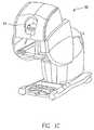
- FIG. 1Cis a front perspective view of a master console of the robotic surgical system in FIG. 1A in accordance with an embodiment of the present invention.
- FIG. 2is a perspective view of a surgical instrument including a force sensor apparatus operably coupled proximal (or inboard) to a wrist joint in accordance with an embodiment of the present invention.
- FIG. 3Ais a perspective view of a force sensor apparatus.
- FIG. 3Billustrates the force sensor of FIG. 3A operably coupled to a shaft and end portion of a surgical instrument.
- FIG. 3Cillustrates the force sensor of FIG. 3A with a protective cover over a portion of the force sensor.
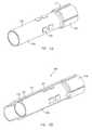
- FIG. 4Ais a perspective view of an inner tube of another force sensor apparatus.
- FIG. 4Bis a partial cross-sectional view of an outer tube/cover over the inner tube of FIG. 4A of the force sensor apparatus.
- FIG. 4Cshows intervening material between the inner and outer tubes of FIG. 4B of the force sensor apparatus and wires or optic fibers operably coupled to the force sensor apparatus.
- FIG. 4Dshows a partial cross-sectional view of the force sensor apparatus operably coupled proximal to (or inboard of) a wrist joint of a surgical instrument.
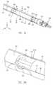
- FIG. 5Ais a perspective view of a force sensor apparatus in accordance with yet another embodiment of the present invention.
- FIG. 5Billustrates an enlarged perspective view of a section of the force sensor apparatus of FIG. 5A .
- FIG. 5Cillustrates a cross-sectional view of the force sensor apparatus of FIG. 5A along line 5 C- 5 C
- FIG. 5 C 1illustrates a magnified section labeled 5 C 1 in FIG. 5C .
- FIG. 5Dillustrates a cross-sectional view of the force sensor apparatus of FIG. 5A along line 5 D- 5 D.
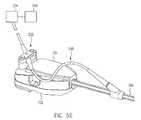
- FIG. 5Eillustrates a strain relief for strain gauge wires or optic fibers in accordance with an embodiment of the present invention.
- FIGS. 6A and 6Billustrate perspective views of another force sensor apparatus and an enlarged view of a portion of the force sensor apparatus in accordance with another embodiment of the present invention.
- FIG. 6Cillustrates an end view of the force sensor apparatus of FIGS. 6A and 6B including radial ribs positioned in non-uniform angles
- FIG. 6 C 1illustrates a magnified section labeled 6 C 1 in FIG. 6C , in accordance with another embodiment of the present invention.
- FIGS. 7A and 7Billustrate a perspective view and an end view of another force sensor apparatus including radial ribs positioned in non-uniform supplementary angles and exposed by apertures on the tube surface
- FIG. 7 B 1illustrates a magnified section labeled 7 B 1 in FIG. 7B , in accordance with another embodiment of the present invention.
- FIG. 8illustrates an end view of another force sensor apparatus including three radial ribs in accordance with another embodiment of the present invention.
- FIGS. 9A and 9Billustrate perspective views of another force sensor apparatus and an enlarged section of the force sensor apparatus, respectively, in accordance with another embodiment of the present invention.
- FIG. 9Cillustrates an end view of the force sensor apparatus of FIGS. 9A and 9B including radial ribs positioned in non-uniform supplementary angles and a central through passage in accordance with another embodiment of the present invention.
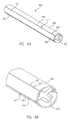
- FIG. 10illustrates a perspective cutaway view of another force sensor apparatus, including apertures exposing radial ribs and a concentric shell surrounding the sensor tube with an annular gap in accordance with an embodiment of the present invention.
- FIGS. 11A-11Cillustrate different views of another force sensor apparatus, including a concentric shell surrounding the sensor tube with an annular heat conducting rib in accordance with an embodiment of the present invention.
- the present inventionprovides a multi-component system, apparatus, and method for sensing forces applied to tissue while performing robotically-assisted surgical procedures on a patient, particularly including open surgical procedures, neurosurgical procedures, and minimally invasive procedures, such as laparoscopy, arthroscopy, thoracoscopy, and the like.
- the apparatus and method of the present inventionare particularly useful as part of a telerobotic surgical system that allows the surgeon to manipulate the surgical instruments through a servomechanism from a location remote from the patient.
- the combined manipulator apparatus or slave and surgical instrument of the present inventionwill usually be driven by a master having the same degrees of freedom (e.g., 3 degrees of freedom for position and 3 degrees of freedom for orientation plus grip) to form a telepresence system with force reflection or other scalar force magnitude display.
- degrees of freedome.g., 3 degrees of freedom for position and 3 degrees of freedom for orientation plus grip
- a description of a suitable slave-master systemcan be found in U.S. Pat. No. 6,574,355, the complete disclosure of which is incorporated herein by reference for all purposes.
- robotic system 10generally includes one or more surgical manipulator assemblies 51 mounted to or near an operating table O and a master control assembly located at a surgeon's console 90 for allowing the surgeon S to view the surgical site and to control the manipulator assemblies 51 .
- the system 10will also include one or more viewing scope assemblies and a plurality of surgical instrument assemblies 54 ( FIG. 2 ) adapted for being removably coupled to the manipulator assemblies 51 (discussed in more detail below).
- Robotic system 10includes at least two manipulator assemblies 51 and preferably at least three manipulator assemblies 51 .
- manipulator assemblies 51will depend on the surgical procedure and the space constraints within the operating room among other factors. As discussed in detail below, one of the assemblies 51 will typically operate a viewing scope assembly (e.g., in endoscopic procedures) for viewing the surgical site, while the other manipulator assemblies 51 operate surgical instruments 54 for performing various procedures on the patient.
- a viewing scope assemblye.g., in endoscopic procedures
- the control assemblymay be located at a surgeon's console 90 which is usually located in the same room as operating table O so that the surgeon may speak to his/her assistant(s) and directly monitor the operating procedure. However, it should be understood that the surgeon S can be located in a different room or a completely different building from the patient.
- the master control assemblygenerally includes a support, a monitor for displaying an image of the surgical site to the surgeon S, and one or more master(s) for controlling manipulator assemblies 51 .
- Master(s)may include a variety of input devices, such as hand-held wrist gimbals, joysticks, gloves, trigger-guns, hand-operated controllers, voice recognition devices, or the like.
- master(s)will be provided with the same degrees of freedom as the combined manipulator 51 and surgical instrument assemblies 54 .
- thisprovides the surgeon with telepresence, the perception that the surgeon is immediately adjacent to and immersed in the surgical site, and intuitiveness, the perception that the master(s) are integral with the instruments 54 so that the surgeon has a strong sense of directly and intuitively controlling instruments 54 as if they are part of or held in his/her hands.
- Position, force, and tactile feedback sensorsmay also be employed on instrument assemblies 54 to transmit position, force, and tactile sensations from the surgical instrument back to the surgeon's hands, ears, or eyes as he/she operates the telerobotic system.
- One suitable system and method for providing telepresence to the operatoris described in U.S. Pat. No. 6,574,355, which has previously been incorporated herein by reference.
- the monitor 94( FIG. 1C ) will be suitably coupled to the viewing scope assembly such that an image of the surgical site is provided adjacent the surgeon's hands on the surgeon console.
- monitor 94will display an image that is oriented so that the surgeon feels that he or she is actually looking directly down onto the operating site.
- an image of the surgical instruments 54appears to be located substantially where the operator's hands are located.
- the real-time imageis a stereo image such that the operator can manipulate the end effector via the hand control as if viewing the workspace in substantially true presence.
- the imagesimulates the viewpoint or orientation of an operator who is physically manipulating the surgical instruments 54 .
- a servo controlis provided for transferring the mechanical motion of masters to manipulator assemblies 51 .
- the servo controlmay be separate from, or integral with, manipulator assemblies 51 .
- the servo controlwill usually provide force and torque feedback from the surgical instruments 51 to the hand-operated masters.
- the servo controlmay include a safety monitoring controller (not shown) to safely halt system operation, or at least inhibit all robot motion, in response to recognized undesirable conditions (e.g., exertion of excessive force on the patient, mismatched encoder readings, etc.).
- the servo controlpreferably has a servo bandwidth with a 3 dB cut off frequency of at least 10 Hz so that the system can quickly and accurately respond to the rapid hand motions used by the surgeon and yet to filter out undesirable surgeon hand tremors.
- manipulator assemblies 51have a relatively low inertia, and the drive motors have relatively low ratio gear or pulley couplings.
- Any suitable conventional or specialized servo controlmay be used in the practice of the present invention, with those incorporating force and torque feedback being particularly preferred for telepresence operation of the system.
- FIG. 2a perspective view is shown of a surgical instrument 54 including a force sensor apparatus 100 operably coupled to a distal end of a rigid shaft 110 and proximal to a wrist joint 121 in accordance with an embodiment of the present invention.
- An end portion 120such as a surgical end effector, is coupled to force sensor apparatus 100 via the wrist joint 121 .
- a housing 150is operably coupled to a proximal end of the rigid shaft 110 and includes an interface 152 which mechanically and electrically couples instrument 54 to the manipulator 51 .
- FIG. 3Ashows a perspective view of force sensor apparatus 100 including in one embodiment a tube 102 including a number (e.g., 3, 4, 6, or 8) of strain gauges 104 (e.g., 104 a and 104 b ) mounted to a surface of tube 102 and oriented axially (parallel to the lengthwise axis z of the tube).
- FIG. 3Bshows the force sensor apparatus 100 of FIG. 3A operably coupled to a shaft 110 and end portion 120 of a surgical instrument.
- FIG. 3Cshows a cross-section view of force sensor apparatus 100 including a cover or sleeve 113 over tube 102 .
- Force sensor apparatus 100is a separately manufacturable module or part adapted for incorporation as part of the shaft 110 of surgical instrument 54 at a prescribed distance from the tip where there may be an articulated wrist with specialized jaws, cutting devices, or other end portion 120 .
- tube 102may be made of a sufficiently strong material and may be spool shaped, including end portions 102 b , 102 c with a depressed portion 102 a therebetween that is smaller in diameter than end portions 102 b , 102 c .
- Strain gauges 104may be mounted on the surface of depressed portion 102 a .
- Proximal tube portion 102 coperably couples to the shaft 110 of surgical instrument 54 and distal tube portion 102 b operably couples to a wrist joint 121 .
- the diameter of the completed force sensor apparatusmatches the diameter of the instrument shaft, thus allowing the entire assembly of the instrument (including the coupled force sensor apparatus) to pass through a cannula or a seal without added friction or snagging.
- Force sensor apparatus 100includes a through passage 109 for end portion actuation cables or rods. End features 108 of end portion 102 b insure secure mounting and angular alignment to the main instrument shaft or the wrist/jaw/other end portion sub-assembly of the instrument.
- Wire leads or optic fibers 116e.g., shielded twisted pairs, coax, or fiber
- the wire leads or optic fibers 116may then be embedded in an adhesive bonding or potting compound such as epoxy.
- cover 113is positioned over and encapsulates the mounted strain gauges 104 and other circuit elements on the surface of the tube 102 , thereby providing mechanical and/or electrical protection of the sensors.
- cover 113is a mechanically protective woven sleeve potted on depressed portion 102 a and is comprised of a woven resin impregnated fiberglass or metal braid electrical shielding.
- strain gauges 104may be spaced in a ring at intervals around the circumference of the tube 102 (e.g., 3 gauges at 120 degrees, 4 gauges at 90 degrees, or 4 gauges at 70 degrees and 110 degrees or other pairs of supplementary angles).
- the signals from the sensorsare combined arithmetically in various sums and differences to obtain measures of transverse forces F x and F y ( FIG.
- 5Efor notifying the surgeon of these forces (e.g., via master(s) or a display). It is understood that by adding a second ring of similarly oriented gauges (e.g., two sets of 3 gauges or two sets of 4 gauges) at a different lengthwise axial position on the tube, additional load-induced bending moment information may be obtained, and dependence of the transverse force data Fx, Fy on instrument wrist length, orientation, and resulting jaw distance may be eliminated.
- similarly oriented gaugese.g., two sets of 3 gauges or two sets of 4 gauges
- various strain gauge typesmay be used, including but not limited to conventional foil type resistance gauges, semiconductor gauges, optic fiber type gauges using Bragg grating or Fabry-Perot technology, or others, such as strain sensing surface acoustic wave (SAW) devices.
- SAWstrain sensing surface acoustic wave
- FBGOptic fiber Bragg grating
- Both fiber technologiesrequire an interrogator unit 334 that decodes the optically encoded strain information into electrical signals compatible with the computer control hardware 340 or display means of the robotic surgical system.
- a processormay then be used to calculate forces according to the signals from the strain gauges/sensors.
- strain gauge bridge circuitsare completed in a manner to give the best signal for bending loads due to the lateral forces (F x and F y ) exerted on the instrument tip jaws.
- active componentssuch as bare die op-amps and passive components such as secondary resistors or capacitors may be attached adjacent to the strain gauges connected by bond wires or thick film circuit traces in the manner of hybrid circuits to amplify, filter, and/or modulate the gauge output signals to reject noise sources.
- passive componentssuch as secondary resistors or capacitors may be attached adjacent to the strain gauges connected by bond wires or thick film circuit traces in the manner of hybrid circuits to amplify, filter, and/or modulate the gauge output signals to reject noise sources.
- Such componentsare not needed for fiber optic gauges.
- Housing 150operably interfaces with a robotic manipulator arm 51 , in one embodiment via a sterile adaptor interface 152 ( FIG. 2 ).
- Applicable housings, sterile adaptor interfaces, and manipulator armsare disclosed in U.S. patent application Ser. No. 11/314,040 filed on Dec. 20, 2005, and U.S. application Ser. No. 11/613,800 filed on Dec. 20, 2006, the full disclosures of which are incorporated by reference herein for all purposes. Examples of applicable shafts, end portions, housings, sterile adaptors, and manipulator arms are manufactured by Intuitive Surgical, Inc. of Sunnyvale, Calif.
- end portion 120has a range of motion that includes pitch and yaw motion about the x- and y-axes and rotation about the z-axis (axes shown in FIG. 3A ).
- These motions as well as actuation of an end effectorare provided via cables in housing 150 and cables and/or rods running through shaft 110 and into housing 150 that transfer motion from the manipulator arm 51 .
- Embodiments of drive assemblies, arms, forearm assemblies, adaptors, and other applicable partsare described for example in U.S. Pat. Nos. 6,331,181, 6,491,701, and 6,770,081, the full disclosures of which are incorporated herein by reference for all purposes.
- various surgical instrumentsmay be improved in accordance with the present invention, including but not limited to tools with and without end effectors, such as jaws, scissors, graspers, needle holders, micro-dissectors, staple appliers, tackers, suction irrigation tools, clip appliers, cutting blades, irrigators, catheters, and suction orifices.
- the surgical instrumentmay comprise an electrosurgical probe for ablating, resecting, cutting or coagulating tissue.
- Such surgical instrumentsare available from Intuitive Surgical, Inc. of Sunnyvale, Calif.
- a calibration processin which combinations of forces and torques are applied to the instrument tip serially or in simultaneous combinations while correction factors and offsets are determined.
- the correction factors and offsetsmay then be applied to the theoretical equations for combining the gauge outputs to obtain F x , F y , and reject F z , T x , and T y .
- Such a calibration processmay be done either by directly calculating the correction factors and offsets or by a learning system such as a neural network embedded in the calibration fixture or in the instrument itself.
- the calibration datamay be programmed into an integrated circuit embedded in the instrument so that the surgical system using the individual instrument can correctly identify and apply its correction factors and offsets while the instrument is in use.
- force sensor apparatus 100is adaptable to the size and shape constraints of various robotic surgical instruments and is suitable for a variety of instruments. Accordingly, end portions 102 b , 102 c may be formed into various applicable shapes and sizes. Furthermore, force sensor apparatus 100 may be manufactured, tested, and calibrated as a separate modular component and brought together with other components in the conventional instrument assembly process. Also, the sensor may be a slip-on module with suitable electrical contacts that mate with contacts on the instrument shaft permitting a higher value sensor to be used with lower cost instruments of limited cycle life. In addition, the sensor structural member 102 may be comprised of an advantageous material, which may be the same or a different material than the instrument shaft 110 whose design considerations may compromise the properties required for the sensor.
- FIGS. 4A through 4Da force sensor apparatus 200 is illustrated.
- the descriptions of substantially similar parts or elements as those described above with respect to FIGS. 3A-3Care applicable in this embodiment with respect to FIGS. 4A-4D , and redundant descriptions may be omitted.
- FIG. 4Ais a perspective view of an inner tube 218 of force sensor apparatus 200 .
- Inner tube 218includes a proximal raised end portion 218 b and a depressed portion 218 a smaller in diameter than raised end portion 218 b .
- Strain gaugesas described above with respect to FIGS. 3A-3C , may be mounted on the surface of depressed portion 218 a .
- Raised end portion 218 bmay include grooves 212 for routing of wire leads or optic fibers from strain gauges 204 .
- FIG. 4Bis a partial cross-sectional view of an outer tube 214 over the inner tube 218 .
- outer tube 214can provide mechanical and thermal protection of strain gauges 204 on inner tube 218 .
- FIG. 4Chighlights elastomeric material 215 between inner tube 218 and outer tube 214 maintaining concentricity of the tubes.
- Leads or optic fibers 216 connecting gauges 204 with data acquisition meansare inlaid into grooves 212 and may be potted in place with epoxy or other adhesive.
- wrist 221 and end effector 220are connected distally to tube 214 .
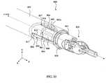
- FIGS. 5A-5Eviews of a surgical instrument including another force sensor apparatus 300 is illustrated in accordance with yet another embodiment of the present invention.
- An end portion 320such as a surgical end effector, is coupled to force sensor apparatus 300 via a wrist joint 321 .
- a housing 150( FIG. 5E ) is operably coupled to a proximal end of a rigid shaft 310 , the housing 150 further including an interface 152 which mechanically and electrically couples the instrument to the manipulator 51 ( FIG. 1B ).
- FIG. 5Bis an enlarged perspective view of an aperture and rib section of the force sensor apparatus of FIG. 5A .
- FIGS. 5C and 5Dare cross-sectional views of the force sensor apparatus of FIG.
- FIG. 5Aalong lines 5 C- 5 C and 5 D- 5 D, respectively, and FIG. 5C illustrates a magnified section labeled 5 C 1 in FIG. 5C .
- FIG. 5Eillustrates an example proximal portion of the surgical instrument including the housing and operably coupling of the instrument to an interrogator 334 and processor 340 .
- the descriptions of substantially similar parts or elements as those described above with respect to FIGS. 1-4are applicable in this embodiment with respect to FIGS. 5A-5E , although redundant descriptions may be omitted.
- force sensor apparatus 300includes a generally annular tube 306 operably coupled to a distal end of rigid shaft 310 and proximal to wrist joint 321 in accordance with an embodiment of the present invention.
- tube 306includes a number of rectangular-shaped apertures 301 cut from tube 306 and a plurality of radial ribs 302 forming through passages 308 for passage of actuation cables, wires, tubes, rods, cautery wires and/or flushing fluids.
- Ribs 302run along and radiate from the z-axis centerline of tube 306 , and a number (e.g., 3, 4, 6, or 8) of strain gauges 304 are oriented parallel to the lengthwise z-axis of the tube and mounted to an outer rib surface 302 a .
- the strain gaugesmay be inlaid into grooves or a depressed area 317 on the outer rib surface 302 a in one example.
- force sensor apparatus 300includes two sets of four apertures 301 cut from the wall of tube 306 at separate axial locations along tube 306 .
- Each of the ribs 302are separated by 90 degrees measured about the z-axis centerline of tube 306 , which forms a cruciform cross-sectional view of the ribs 302 , as shown in FIGS. 5C and 5D .
- Ribs 302form four through passages 308 .
- ribs 302may extend along the entire length of tube 306 thereby forming internal through passages 308 along the entire length of tube 306 , or ribs 302 may extend along a portion(s) of the length of tube 306 , thereby forming internal through passages along a portion or portions of the length of tube 306 .
- Force sensor apparatus 300is capable of sensing bending moments due to lateral forces applied to the wrist joint 321 or its specialized end portion 320 .
- apertures 301 and ribs 302provide for regions of controlled stress and strain when subjected to bending moments, which may be measured by fiber optic strain gauges 304 embedded in grooves 317 along an outer surface of the ribs and sensor body parallel to the lengthwise z-axis of tube 306 .
- Through passages 308permit cables, wires, tubes, or rigid tendons to pass through the sensor apparatus body to actuate the distal wrist joint(s) and/or control the end portion.
- tube 306 and ribs 302may be made of a sufficiently strong but elastic material to allow sensing of stress and strain without mechanical failure.
- Tube 306 and ribs 302are further comprised of material with a sufficiently low modulus of elasticity to give a sufficient strain signal under an applied load, a sufficiently high strain at yield to give adequate safety margin above the maximum design load, and a sufficiently high thermal diffusivity to promote rapid thermal equilibrium (therefore reducing thermal disturbances to sensor output signals) when subject to localized or asymmetric thermal disturbances from tissue contact or endoscope illumination.
- the plurality of radial ribs 302may be comprised of a high thermal diffusivity material, such as an aluminum alloy (e.g., 6061-T6 aluminum) or a copper alloy (e.g., GlidCop® AL-60) or a silver alloy to reduce the temperature difference between opposing gauges under transient thermal disturbances by providing a direct thermal pathway between opposing gauges.
- a high thermal diffusivity materialsuch as an aluminum alloy (e.g., 6061-T6 aluminum) or a copper alloy (e.g., GlidCop® AL-60) or a silver alloy to reduce the temperature difference between opposing gauges under transient thermal disturbances by providing a direct thermal pathway between opposing gauges.
- tube 306may be comprised of metal alloys, treated metals, or plated metals, such as of aluminum, copper, or silver, which allow for adequate strain, mechanical failure safety margin, and high thermal diffusivity.
- metal alloyssuch as of aluminum, copper, or silver
- 6061-T6 aluminumwhich is an aluminum alloy that is heat treated and aged
- GlidCop® AL-60which is copper that is dispersion strengthened with ultrafine particles of aluminum oxide, or a dispersion strengthened silver, may be used to form tube 306 and ribs 302 .
- both the plurality of ribs and the tube 302may be comprised of a high thermal diffusivity material, such as an aluminum alloy (e.g., 6061-T6 aluminum) or a copper alloy (e.g., GlidCop® AL-60) or silver alloy to reduce transient and/or steady-state temperature differences between groups of strain gauges separated along the z-axis.
- a high thermal diffusivity materialsuch as an aluminum alloy (e.g., 6061-T6 aluminum) or a copper alloy (e.g., GlidCop® AL-60) or silver alloy to reduce transient and/or steady-state temperature differences between groups of strain gauges separated along the z-axis.
- the present inventionallows for a low bending moment of inertia to increase a strain signal to noise signal ratio consistent with a materials choice and rib design meeting the need for high thermal diffusivity and a direct thermal path between opposing strain gauges while also providing passage for actuation cables, wires, tubes, and/or rods.
- Wire leads or optic fibers 316(e.g., shielded twisted pairs, coax, or fiber) coupled to the strain gauges 304 may be inlaid into grooves 317 on tube 306 , the outer rib surface 302 a , and matching grooves 319 in shaft 310 of the surgical instrument.
- the wire leads or optic fibers 316may then be embedded in an adhesive potting compound such as epoxy.
- strain gauges 304may be spaced in a ring at intervals around the circumference of the tube 306 mounted on ribs 302 (e.g., 3 gauges at 120 degrees, 4 gauges at 90 degrees, 4 gauges at 70 and 110 degrees or other supplementary pairs of angles).
- the signals from the sensorsare combined arithmetically in various sums and differences to obtain measures of the transverse forces F x , F y , and to reject axial forces F z exerted upon the instrument tip and to reject wrist torques about the two axes perpendicular to the shaft axis (i.e., axes x and y).
- the measurement of the transverse forcesis made independent of the orientation and effective lever arm length of an articulated wrist mechanism at the distal end of the instrument as well as wrist friction moments and actuator cable tensions when two axially separated sets or rings of gauges are utilized.
- Forces exerted against end portion 320are detected by the force sensing elements, which may be operably coupled to the servo control or surgeon display means via an interrogator 334 and to a processor 340 for notifying the surgeon of these forces (e.g., via master(s) or a display means). It is understood that by adding a second ring of similarly oriented gauges (e.g., two sets of 3 gauges or two sets of 4 gauges) at a different position along the z-axis of the tube, additional side load-induced moment information can be obtained, and dependence of the force data on instrument wrist length, orientation, and resulting jaw distance and cable tensions, can be eliminated.
- similarly oriented gaugese.g., two sets of 3 gauges or two sets of 4 gauges
- various strain gaugesmay be used, including but not limited to conventional foil type resistance gauges, semiconductor gauges, optic fiber type gauges using Bragg grating or Fabry-Perot technology, or others, such as strain sensing surface acoustic wave (SAW) devices.
- SAWstrain sensing surface acoustic wave
- FBGOptic fiber Bragg grating
- Fiber optic gaugesmay also be desirable because of their immunity to disturbance from cautery and other electromagnetic noise.
- FBG strain gaugesin conventional fiber such as SMF-28 are their inherent positive temperature sensitivity, being especially problematic when the FBG strain gauges are mounted to materials with a positive thermal expansion coefficient, which adds to the temperature sensitivity of the FGB strain gauges. Temperature sensitivity limits the accuracy of a force transducer utilizing FBGs and positive thermal expansion coefficient substrate materials, especially under asymmetric transient thermal loads that may occur in surgery.
- Intrinsic and extrinsic temperature compensation of FBG strain sensorsmay be accomplished with additional gratings written in the same or nearby region of the fiber and may include the use of additional fibers, exotic doped fibers spliced together, highly bi-refringent fiber or other means to differentiate thermal responses so that simultaneous equations in strain and temperature with respect to wavelength shift can be solved to obtain the strain independent of the temperature of any single grating. These methods typically require additional interrogator channels or exotic interrogation methods.
- the plurality of fiber optic strain gauges 304may be comprised of a negative thermo-optic coefficient optical fiber material, such as binary or ternary phosphate glass fiber, fluoride glass fiber, oxy-fluoride glass fiber, tellurite glass fiber, or a polymer fiber.
- the negative thermo-optic coefficient fiberadvantageously reduces or eliminates the combined effect of a positive thermo-optic coefficient fiber, such as SMF-28 or other doped fiber, and the positive thermal expansion coefficient of the sensor body material.
- embodiments of the present inventionprovide apparatus and methods for improved thermal stability when subjected to temperature changes, such as when entering the patient body from a lower temperature operating room environment, contacting warm living tissue, absorbing incident light from an endoscope illuminator, or other source of thermal disturbance that may occur during surgery. Also, the present invention provides for cost savings, relative ease of manufacture, higher field reliability, and accurate strain measurements.
- interrogator unit 334( FIG. 5E ) that decodes the optically encoded strain information into electrical signals compatible with the computer control hardware of the robotic surgical system.
- a processor 340( FIG. 5E ) operably coupled to the interrogator unit 334 may then be used to calculate forces according to the signals from the strain gauges/sensors.
- active componentssuch as bare die op-amps and passive components such as secondary resistors or capacitors may be attached adjacent to the strain gauges connected by bond wires or thick film circuit traces in the manner of hybrid circuits to amplify, filter, and/or modulate the gauge output signals to reject noise sources.
- passive componentssuch as secondary resistors or capacitors may be attached adjacent to the strain gauges connected by bond wires or thick film circuit traces in the manner of hybrid circuits to amplify, filter, and/or modulate the gauge output signals to reject noise sources.
- Such componentsare not needed for fiber optic gauges.
- force sensor apparatus 300is a separately manufactured module or part adapted for incorporation as part of the shaft 310 of a laparoscopic surgical instrument at a prescribed distance from the tip where there may be an articulated wrist with specialized jaws, cutting devices, or other end portion 320 .
- a proximal portion of tube 306operably couples to the shaft 310 of the surgical instrument and a distal portion of tube 306 operably couples to wrist joint 321 .
- the diameter of the completed force sensor apparatusmatches the diameter of the instrument shaft, thus allowing the entire assembly of the instrument (including the coupled force sensor apparatus) to pass through a cannula or a seal without added friction or snagging.
- the surgical instrumentmay be manufactured with a force sensor portion integrated as a part of shaft 310 (i.e., force sensor apparatus 300 is not separable from the shaft).
- the surgical instrument to which force sensor apparatus 300 couplesmay also include a service loop 330 ( FIG. 5E ) of conductive traces or optic fibers at the proximal end of the instrument shaft 310 and a cable swivel mechanism 332 permitting the substantially free rotation of the instrument shaft while conducting the input gauge excitation power or light and electrical or optical output gauge signals to the interrogator unit 334 .
- the housing 150operably interfaces with a robotic manipulator arm, in one embodiment via a sterile adaptor interface.
- Applicable housings, sterile adaptor interfaces, and manipulator armsare disclosed in U.S. patent application Ser. No. 11/314,040 filed on Dec. 20, 2005, and U.S. patent application Ser. No. 11/613,800 filed on Dec. 20, 2006, the full disclosures of which are incorporated by reference herein for all purposes. Examples of applicable shafts, end portions, housings, sterile adaptors, and manipulator arms are manufactured by Intuitive Surgical, Inc. of Sunnyvale, Calif.
- end portion 320has a range of motion that includes pitch and yaw motion about the x- and y-axes and rotation about the z-axis.
- These motions as well as actuation of an end effectorare provided via cables in the housing 150 and cables and/or rods running through the shaft and into the housing that transfer motion from the manipulator arm.
- Embodiments of drive assemblies, arms, forearm assemblies, adaptors, and other applicable partsare described for example in U.S. Pat. Nos. 6,331,181, 6,491,701, and 6,770,081, the full disclosures of which are incorporated herein by reference for all purposes.
- various surgical instrumentsmay be improved in accordance with the present invention, including but not limited to tools with and without end effectors, such as jaws, scissors, graspers, needle holders, micro-dissectors, staple appliers, tackers, suction irrigation tools, clip appliers, cutting blades, hooks, sealers, lasers, irrigators, catheters, and suction orifices.
- the surgical instrumentmay comprise an electrosurgical probe for ablating, resecting, cutting or coagulating tissue.
- Such surgical instrumentsare manufactured by Intuitive Surgical, Inc. of Sunnyvale, Calif.
- the calibration processmay be used in which combinations of forces and torques are applied to the instrument tip serially, simultaneously, or in combinations while correction factors and offsets are determined to apply to the theoretical equations for combining the gauge outputs to obtain F x , F y and reject F z , T x , and T y .
- This calibrationmay be done either by directly calculating the correction factors and offsets or by a learning system such as a neural network embedded in the calibration fixture or in the instrument itself.
- the calibration datamay be programmed into an integrated circuit embedded in the instrument so that the surgical system using the individual instrument can correctly identify and apply its correction factors and offsets while the instrument is in use.
- force sensor apparatus 300 of the present inventionis adaptable to the size and shape constraints of robotic endoscopic surgical instruments and is suitable for a variety of instruments.
- force sensor apparatus 300may be manufactured, tested, and calibrated as a separate modular component and brought together with other components in the conventional instrument assembly process or as an integrated part of the instrument shaft 310 .
- the sensormay be a slip-on module permitting a higher value sensor to be used with lower cost instruments of limited cycle life.
- FIGS. 6 A- 6 C 1 , 7 A- 7 B 1 , 8 , and 9 A- 9 Cillustrate force sensor apparatus in accordance with other embodiments of the present invention.
- the descriptions of substantially similar parts or elements as those described above with respect to FIGS. 5A-5Eare applicable in these embodiments although redundant descriptions may be omitted.
- a force sensor apparatus 400including four ribs 402 in diametrically opposite pairs at skewed supplementary angles (e.g., 70 degrees and 110 degrees) about a z-axis centerline of a tube 406 .
- Ribs 402extend radially within tube 406 from the z-axis centerline of the tube providing four through passages 408 a and 408 b for passage of actuation cables, wires, tubes, rods, cautery wires and/or flushing fluids.
- a larger through passage 408 autilizing skewed angles allows for easier passage of cables, wires, tubes, and/or rods through tube 406 (e.g., three hypodermic tubes may be passed per 110 degree channel).
- tube 406does not include apertures through the wall of tube 406 .
- the combined stiffness of tube 406 and ribs 402still allow for a strong strain signal to noise signal ratio consistent with a materials choice and rib design meeting the need for high thermal diffusivity and a direct thermal path between opposing strain gauges while also providing passage for actuation cables, wires, tubes, and/or rods.
- a number of strain gauges 404are oriented parallel to the lengthwise z-axis of the tube and mounted to an outer rib surface 402 a .
- the strain gaugesmay be inlaid into grooves or a depressed area 417 on the outer rib surface 402 a in one example.
- Wire leads or optic fibers 416e.g., shielded twisted pairs, coax, or fiber
- the wire leads or optic fibers 416may then be embedded in an adhesive potting compound such as epoxy.
- FIGS. 6 C and 6 C 1an end view of force sensor apparatus 400 and a magnified section labeled 6 C 1 in FIG. 6C are respectively illustrated.
- a thermal shielding over the strain gaugesmay be provided in accordance with another embodiment of the present invention.
- a thermal shunt shell 452is provided over tube 406 with an insulating fluid (gas or liquid) filled or evacuated gap 450 being provided between the outer surface of tube 406 and the inner surface of thermal shunt shell 452 .
- Thermal shunt shell 452may be comprised of a high thermal diffusivity material, such as an aluminum alloy (e.g., 6061-T6 aluminum) or a copper alloy (e.g., GlidCop® AL-60) or a silver alloy.
- a light reflective surface or coating 453may be provided over thermal shunt shell 452 , which may deflect light and reduce localized heating of the force sensor apparatus, for example from endoscope illumination.
- An insulating coating 454may also be provided over thermal shunt shell 452 , the insulating coating 454 being comprised of a substantially transparent plastic shrink polymer in one example.
- the thermal shielding over the sensor tube 406 and the strain gauges 404 as described aboveallows for more uniform heat/thermal diffusion among the gauges, being particularly advantageous for mitigating asymmetric thermal loads upon the instrument.
- the thermal shielding described aboveis applicable for various embodiments of the present invention.
- a force sensor apparatus 500including four ribs 502 paired at skewed angles (e.g., 70 degrees and 110 degrees) about a z-axis centerline of a tube 506 .
- Ribs 502extend radially within tube 506 from the z-axis centerline of the tube providing four through passages 508 a and 508 b for passage of actuation cables, wires, tubes, rods cautery wires and/or flushing fluids.
- a larger through passage 508 a utilizing skewed anglesallows for easier passage of cables, wires, tubes, and/or rods through tube 506 (e.g., three hypodermic tubes may be passed per 110 degree channel).
- tube 506include apertures 501 provided through the wall of tube 506 .
- the reduced stiffness of exposed ribs 502allow for a strong strain signal to noise signal ratio consistent with a materials choice and rib design meeting the need for high thermal diffusivity and a direct thermal path between opposing strain gauges while also providing passage for actuation cables, wires, tubes, rods, and the like.
- a number of strain gauges 504are oriented parallel to the lengthwise z-axis of the tube and mounted to an outer rib surface 502 a .
- the strain gaugesmay be inlaid into grooves or a depressed area 517 on the outer rib surface 502 a in one example.
- Wire leads or optic fibers 516e.g., shielded twisted pairs, coax, or fiber
- the wire leads or optic fibers 516 in grooves 517may then be embedded in an adhesive potting compound such as epoxy.
- FIG. 8illustrates a cross-sectional view of another force sensor apparatus which includes three ribs 602 separated by 120 degrees about a z-axis centerline of the force sensor apparatus tube 606 .
- Ribs 602provide three through passages 608 .
- Wire leads or optic fibers 616e.g., shielded twisted pairs, coax, or fiber
- strain gaugesmay be inlaid into grooves 617 on an instrument tube, an outer rib surface, and matching grooves in a shaft of the surgical instrument.
- a force sensor apparatus 700including four ribs 702 paired at skewed angles (e.g., 70 degrees and 110 degrees) about a z-axis centerline of a tube 706 .
- Ribs 702extend radially within tube 706 from the z-axis centerline of the tube providing through passages 708 a and 708 b .
- force sensor apparatus 700also includes a central through passage 708 c along a lengthwise axis of tube 706 in accordance with another embodiment of the present invention.
- the through passagesmay be used for passage of actuation cables, wires, tubes, rods, and/or fluids.
- tube 706does not include apertures through the wall of the tube but apertures exposing portions of the interior ribs are within the scope of the present invention. Furthermore, the combined stiffness of tube 706 and ribs 702 still allow for a strong strain signal to noise signal ratio consistent with a materials choice and rib design meeting the need for high thermal diffusivity and a thermal path between opposing strain gauges while also providing passage for actuation cables, wires, tubes, rods, and/or fluids.
- a number of strain gauges 704are oriented parallel to the lengthwise z-axis of the tube and mounted to an outer rib surface 702 a .
- the strain gaugesmay be inlaid into grooves or a depressed area 717 on the outer rib surface 702 a in one example.
- Wire leads or optic fibers 716e.g., shielded twisted pairs, coax, or fiber
- the wire leads or optic fibers 716may then be embedded in an adhesive potting compound such as epoxy.
- Force sensor apparatus 800includes a generally annular tube 806 operably coupled to an end portion 820 via a wrist joint 821 .
- tube 806includes a number of rectangular-shaped apertures 801 cut from tube 806 and a plurality of radial ribs 802 forming through passages 808 for passage of wrist actuation cables, wires, tubes, or rods, cautery wires and/or flushing fluids.
- Ribs 802run along and radiate from the z-axis centerline of tube 806 , and a plurality of strain gauges 804 are oriented parallel to the lengthwise z-axis of the tube and mounted to an outer rib surface 802 a .
- the strain gaugesmay be inlaid into grooves or a depressed area 817 on the outer rib surface 802 a in one example.
- Wire leads or optic fibers 816e.g., shielded twisted pairs, coax, or fiber
- the wire leads or optic fibers 816may then be embedded in an adhesive potting compound such as epoxy.
- each of the ribs 802are separated by 90 degrees measured about the z-axis centerline of tube 806 , which forms a cruciform cross-sectional view of the ribs 802 .
- Other separation angles for the ribsare within the scope of the present invention, as outlined above.
- ribs 802may extend along the entire length of tube 806 thereby forming internal through passages 808 along the entire length of tube 806 , or ribs 802 may extend along a portion(s) of the length of tube 806 , thereby forming internal through passages along a portion or portions of the length of tube 806 .
- force sensor apparatus 800is capable of sensing bending moments due to lateral forces applied to the wrist joint 821 or its specialized end portion 820 .
- apertures 801 and ribs 802provide for regions of controlled stress and strain when subjected to bending moments, which may be measured by the fiber optic strain gauges 804 embedded in the grooves 817 along the outer surface of the ribs and sensor body parallel to the lengthwise z-axis of tube 806 .
- tube 806 and ribs 802may be comprised of material with a sufficiently low modulus of elasticity to give a sufficient strain signal under an applied load, a sufficiently high strain at yield to give adequate safety margin above the maximum design load, and a sufficiently high thermal diffusivity to promote rapid thermal equilibrium (therefore reducing thermal disturbances to sensor output signals) when subject to localized or asymmetric thermal disturbances from tissue contact or endoscope illumination.
- the plurality of radial ribs 802may be comprised of a high thermal diffusivity material, such as an aluminum alloy (e.g., 6061-T6 aluminum) or a copper alloy (e.g., GlidCop® AL-60) or silver alloy to reduce the temperature difference between opposing gauges under transient thermal disturbances by providing a direct thermal pathway between opposing gauges.
- the plurality of fiber optic gauges 804may be comprised of a negative thermo-optic coefficient optical fiber material, such as binary or ternary phosphate glass fiber, fluoride glass fiber, oxy-fluoride glass fiber, tellurite glass fiber, or a polymer fiber.
- the negative thermo-optic coefficient fiberadvantageously reduces or eliminates the combined effect of a positive thermo-optic coefficient fiber, such as SMF-28 or other doped fiber, and the positive thermal expansion coefficient of the sensor body material.
- tube 806may be comprised of metal alloys, treated metals, or plated metals, such as of aluminum, copper, or silver, which allow for adequate strain, mechanical failure safety margin, and high thermal diffusivity.
- metal alloyssuch as of aluminum, copper, or silver
- 6061-T6 aluminumwhich is an aluminum alloy that is heat treated and aged
- GlidCop® AL-60which is copper that is dispersion strengthened with ultrafine particles of aluminum oxide, or a dispersion strengthened silver, may be used to form both tube 806 and ribs 802 .
- both the plurality of ribs 802 and the tube 806may be comprised of a high thermal diffusivity material, such as an aluminum alloy (e.g., 6061-T6 aluminum) or a copper alloy (e.g., GlidCop® AL-60) or silver alloy, to reduce transient and/or steady-state temperature differences between groups of strain gauges separated along the z-axis.
- a high thermal diffusivity materialsuch as an aluminum alloy (e.g., 6061-T6 aluminum) or a copper alloy (e.g., GlidCop® AL-60) or silver alloy
- a thermal shieldingmay be provided over the strain gauges 804 in accordance with another embodiment of the present invention.
- a thermal shunt shell 852is provided over tube 806 with an insulating fluid (gas or liquid) filled or evacuated gap 850 being provided between the outer surface of tube 806 and the inner surface of thermal shunt shell 852 .
- Thermal shunt shell 852may be mechanically and thermally isolated from the strain gauges by providing compliant elastomer rings 830 between the shunt shell 852 and the tube 806 to prevent interference with the applied surgical forces and to insulate the sensor.
- Thermal shunt shell 852may be comprised of a high diffusivity material, such as an aluminum alloy (e.g., 6061-T6 aluminum) or a copper alloy (e.g., GlidCop® AL-60) or silver alloy.
- a light reflective surface or coatingmay be provided over thermal shunt shell 852 , which may deflect light and reduce localized heating of the force sensor apparatus, for example from endoscope illumination.
- An insulating coatingmay also be provided over thermal shunt shell 852 , the insulating coating being comprised of a substantially transparent plastic shrink polymer in one example.
- the thermal shielding over the strain gauges as described aboveallows for more uniform heat/thermal diffusion among the sensors, being particularly advantageous for mitigating asymmetric or transient thermal loads upon the instrument.
- the thermal shielding described aboveis applicable for various embodiments of the present invention.
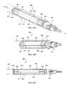
- a force sensor apparatus 900includes a generally annular tube 906 operably coupled to an end effector via a wrist joint 921 .
- tube 906includes a plurality of radial ribs forming through passages for passage of wrist actuation cables, wires, tubes, or rods, cautery wires, flushing fluids, and the like.
- a plurality of strain gauges 904are oriented parallel to the lengthwise z-axis of the tube and mounted to an outer rib surface.
- the strain gaugesmay be inlaid into grooves or a depressed area 917 on the outer rib surface in one example.
- Wire leads or optic fibers 916e.g., shielded twisted pairs, coax, or fiber
- the wire leads or optic fibers 916may then be embedded in an adhesive potting compound such as epoxy.
- each of the ribsmay be separated by 90 degrees measured about the z-axis centerline of tube 906 , which forms a cruciform cross-sectional view of the ribs.
- Other separation angles for the ribsare within the scope of the present invention, as outlined above.
- the ribsmay extend along the entire length of tube 906 thereby forming internal through passages along the entire length of tube 906 , or the ribs may extend along a portion(s) of the length of tube 906 , thereby forming internal through passages along a portion or portions of the length of tube 906 .
- force sensor apparatus 900is capable of sensing bending moments due to lateral forces applied to the wrist joint or its specialized end portion.
- the ribsprovide for regions of controlled stress and strain when subjected to bending moments, which may be measured by the fiber optic strain gauges 904 embedded in the grooves 917 along the outer surface of the ribs and sensor body parallel to the lengthwise z-axis of tube 906 .
- tube 906 and the ribsmay be comprised of material with a sufficiently low modulus of elasticity to give a sufficient strain signal under an applied load, a sufficiently high strain at yield to give adequate safety margin above the maximum design load, and a sufficiently high thermal diffusivity to promote rapid thermal equilibrium (therefore reducing thermal disturbances to sensor output signals) when subject to localized or asymmetric thermal disturbances from tissue contact or endoscope illumination.
- the plurality of radial ribsmay be comprised of a high thermal diffusivity material, such as an aluminum alloy (e.g., 6061-T6 aluminum) or a copper alloy (e.g., GlidCop® AL-60) or a silver alloy to reduce the temperature difference between opposing gauges under transient thermal disturbances by providing a direct thermal pathway between opposing gauges.
- the plurality of fiber optic gauges 904may be comprised of a negative thermo-optic coefficient optical fiber material, such as binary or ternary phosphate glass fiber, fluoride glass fiber, oxy-fluoride glass fiber, tellurite glass fiber, or a polymer fiber.
- the negative thermo-optic coefficient fiberadvantageously reduces or eliminates the combined effect of a positive thermo-optic coefficient fiber, such as SMF-28 or other doped fiber, and the positive thermal expansion coefficient of the sensor body material.
- tube 906may be comprised of metal alloys, treated metals, or plated metals, such as of aluminum, copper, or silver, which allow for adequate strain, mechanical failure safety margin, and high thermal diffusivity.
- metal alloyssuch as of aluminum, copper, or silver
- 6061-T6 aluminumwhich is an aluminum alloy that is heat treated and aged
- GlidCop® AL-60which is copper that is dispersion strengthened with ultrafine particles of aluminum oxide, or a dispersion strengthened silver, may be used to form both tube 906 and the plurality of ribs.
- both the plurality of ribs and the tube 906may be comprised of a high thermal diffusivity material, such as an aluminum alloy (e.g., 6061-T6 aluminum) or a copper alloy (e.g., GlidCop® AL-60) or a silver alloy, to reduce transient and/or steady-state temperature differences between groups of strain gauges separated along the z-axis.
- a high thermal diffusivity materialsuch as an aluminum alloy (e.g., 6061-T6 aluminum) or a copper alloy (e.g., GlidCop® AL-60) or a silver alloy
- a thermal shieldingmay be provided over the strain gauges 904 in accordance with another embodiment of the present invention.
- a thermal shunt shell 952is provided over tube 906 with an insulating fluid (gas or liquid) filled or evacuated gap 950 being provided between the outer surface of tube 906 and the inner surface of thermal shunt shell 952 .
- Thermal shunt shell 952may be mechanically and thermally isolated from the strain gauges by providing compliant elastomer rings 930 between the shunt shell 952 and the tube 906 to prevent interference with the applied surgical forces and to insulate the sensor.
- thermal shunt shell 952includes an annular heat conducting rib 954 midway between strain gauges 904 in the axial direction (i.e., the z-axis direction).
- Heat conducting rib 954contacts an outer surface of tube 906 and conducts heat from the outer shunt shell to the tube 906 such that external thermal disturbances will be more uniformly diffused among the sensors.
- heat conducting rib 954may be comprised of the same material as thermal shunt shell 952 , which may be comprised of a high diffusivity material, such as an aluminum alloy (e.g., 6061-T6 aluminum) or a copper alloy (e.g., GlidCop® AL-60) or a silver alloy.
- Heat conducting rib 954may be comprised of a different material than thermal shunt shell 952 in other embodiments but will be comprised of a high thermal diffusivity material.
- the thermal shielding with heat conducting rib midway between the groups of strain gauges as described aboveallows for more uniform heat/thermal diffusion among the sensors, being particularly advantageous for mitigating asymmetric or transient thermal loads upon the instrument.
- the thermal shielding described aboveis applicable for various embodiments of the present invention.
- a light reflective surface or coatingmay be provided over thermal shunt shell 952 , which may deflect light and reduce localized heating of the force sensor apparatus, for example from endoscope illumination.
- An insulating coatingmay also be provided over thermal shunt shell 952 , the insulating coating being comprised of a substantially transparent plastic shrink polymer in one example.
- Embodiments described aboveillustrate but do not limit the invention. It should also be understood that numerous modifications and variations are possible in accordance with the principles of the present invention. For example, the number of strain gauges and their configuration may vary but must allow for applicable force and torque determinations and noise rejection. Similarly, the number of ribs and angle between ribs may vary from those described above. Furthermore, the embodiments of force sensor apparatus described above may be integrated with a surgical instrument upon manufacture as a non-separable part of the shaft. Accordingly, the scope of the invention is defined only by the following claims.
Landscapes
- Health & Medical Sciences (AREA)
- Engineering & Computer Science (AREA)
- Surgery (AREA)
- Life Sciences & Earth Sciences (AREA)
- Robotics (AREA)
- Biomedical Technology (AREA)
- Nuclear Medicine, Radiotherapy & Molecular Imaging (AREA)
- Heart & Thoracic Surgery (AREA)
- Medical Informatics (AREA)
- Molecular Biology (AREA)
- Animal Behavior & Ethology (AREA)
- General Health & Medical Sciences (AREA)
- Public Health (AREA)
- Veterinary Medicine (AREA)
- General Physics & Mathematics (AREA)
- Physics & Mathematics (AREA)
- Manipulator (AREA)
- Surgical Instruments (AREA)
Abstract
Description
Claims (15)
Priority Applications (6)
| Application Number | Priority Date | Filing Date | Title |
|---|---|---|---|
| US12/414,534US8561473B2 (en) | 2007-12-18 | 2009-03-30 | Force sensor temperature compensation |
| US12/541,848US8491574B2 (en) | 2009-03-30 | 2009-08-14 | Polarization and temperature insensitive surgical instrument force transducer |
| US13/922,512US20130282024A1 (en) | 2009-03-30 | 2013-06-20 | Polarization and temperature insensitive surgical instrument force transducer |
| US14/032,491US9855102B2 (en) | 2007-12-18 | 2013-09-20 | Force sensor temperature compensation |
| US15/827,864US10390896B2 (en) | 2007-12-18 | 2017-11-30 | Force sensor temperature compensation |
| US16/517,259US11571264B2 (en) | 2007-12-18 | 2019-07-19 | Force sensor temperature compensation |
Applications Claiming Priority (2)
| Application Number | Priority Date | Filing Date | Title |
|---|---|---|---|
| US11/958,772US8496647B2 (en) | 2007-12-18 | 2007-12-18 | Ribbed force sensor |
| US12/414,534US8561473B2 (en) | 2007-12-18 | 2009-03-30 | Force sensor temperature compensation |
Related Parent Applications (1)
| Application Number | Title | Priority Date | Filing Date |
|---|---|---|---|
| US11/958,772Continuation-In-PartUS8496647B2 (en) | 2005-03-30 | 2007-12-18 | Ribbed force sensor |
Related Child Applications (2)
| Application Number | Title | Priority Date | Filing Date |
|---|---|---|---|
| US12/541,848Continuation-In-PartUS8491574B2 (en) | 2009-03-30 | 2009-08-14 | Polarization and temperature insensitive surgical instrument force transducer |
| US14/032,491DivisionUS9855102B2 (en) | 2007-12-18 | 2013-09-20 | Force sensor temperature compensation |
Publications (2)
| Publication Number | Publication Date |
|---|---|
| US20090192522A1 US20090192522A1 (en) | 2009-07-30 |
| US8561473B2true US8561473B2 (en) | 2013-10-22 |
Family
ID=40899987
Family Applications (4)
| Application Number | Title | Priority Date | Filing Date |
|---|---|---|---|
| US12/414,534Active2031-04-28US8561473B2 (en) | 2007-12-18 | 2009-03-30 | Force sensor temperature compensation |
| US14/032,491Active2029-07-06US9855102B2 (en) | 2007-12-18 | 2013-09-20 | Force sensor temperature compensation |
| US15/827,864ActiveUS10390896B2 (en) | 2007-12-18 | 2017-11-30 | Force sensor temperature compensation |
| US16/517,259Active2028-06-21US11571264B2 (en) | 2007-12-18 | 2019-07-19 | Force sensor temperature compensation |
Family Applications After (3)
| Application Number | Title | Priority Date | Filing Date |
|---|---|---|---|
| US14/032,491Active2029-07-06US9855102B2 (en) | 2007-12-18 | 2013-09-20 | Force sensor temperature compensation |
| US15/827,864ActiveUS10390896B2 (en) | 2007-12-18 | 2017-11-30 | Force sensor temperature compensation |
| US16/517,259Active2028-06-21US11571264B2 (en) | 2007-12-18 | 2019-07-19 | Force sensor temperature compensation |
Country Status (1)
| Country | Link |
|---|---|
| US (4) | US8561473B2 (en) |
Cited By (134)
| Publication number | Priority date | Publication date | Assignee | Title |
|---|---|---|---|---|
| US20140308061A1 (en)* | 2013-04-16 | 2014-10-16 | Caterpillar Inc. | Method and System for Detecting Engagement with a Work Tool Accessory |
| US9078685B2 (en) | 2007-02-16 | 2015-07-14 | Globus Medical, Inc. | Method and system for performing invasive medical procedures using a surgical robot |
| US20160216167A1 (en)* | 2005-03-30 | 2016-07-28 | Intuitive Surgical Operations, Inc. | Ribbed force sensor |
| US9498300B1 (en)* | 2015-07-30 | 2016-11-22 | Novartis Ag | Communication system for surgical devices |
| US9782229B2 (en) | 2007-02-16 | 2017-10-10 | Globus Medical, Inc. | Surgical robot platform |
| US9855102B2 (en) | 2007-12-18 | 2018-01-02 | Intuitive Surgical Operations, Inc. | Force sensor temperature compensation |
| US10080615B2 (en) | 2015-08-12 | 2018-09-25 | Globus Medical, Inc. | Devices and methods for temporary mounting of parts to bone |
| US10117632B2 (en) | 2016-02-03 | 2018-11-06 | Globus Medical, Inc. | Portable medical imaging system with beam scanning collimator |
| US10136954B2 (en) | 2012-06-21 | 2018-11-27 | Globus Medical, Inc. | Surgical tool systems and method |
| US10231791B2 (en) | 2012-06-21 | 2019-03-19 | Globus Medical, Inc. | Infrared signal based position recognition system for use with a robot-assisted surgery |
| US10292778B2 (en) | 2014-04-24 | 2019-05-21 | Globus Medical, Inc. | Surgical instrument holder for use with a robotic surgical system |
| US10357184B2 (en) | 2012-06-21 | 2019-07-23 | Globus Medical, Inc. | Surgical tool systems and method |
| US10448910B2 (en) | 2016-02-03 | 2019-10-22 | Globus Medical, Inc. | Portable medical imaging system |
| US10573023B2 (en) | 2018-04-09 | 2020-02-25 | Globus Medical, Inc. | Predictive visualization of medical imaging scanner component movement |
| US10569794B2 (en) | 2015-10-13 | 2020-02-25 | Globus Medical, Inc. | Stabilizer wheel assembly and methods of use |
| US10580217B2 (en) | 2015-02-03 | 2020-03-03 | Globus Medical, Inc. | Surgeon head-mounted display apparatuses |
| US10646283B2 (en) | 2018-02-19 | 2020-05-12 | Globus Medical Inc. | Augmented reality navigation systems for use with robotic surgical systems and methods of their use |
| US10660712B2 (en) | 2011-04-01 | 2020-05-26 | Globus Medical Inc. | Robotic system and method for spinal and other surgeries |
| US10675094B2 (en) | 2017-07-21 | 2020-06-09 | Globus Medical Inc. | Robot surgical platform |
| US10813704B2 (en) | 2013-10-04 | 2020-10-27 | Kb Medical, Sa | Apparatus and systems for precise guidance of surgical tools |
| US10842453B2 (en) | 2016-02-03 | 2020-11-24 | Globus Medical, Inc. | Portable medical imaging system |
| US10866119B2 (en) | 2016-03-14 | 2020-12-15 | Globus Medical, Inc. | Metal detector for detecting insertion of a surgical device into a hollow tube |
| US10893912B2 (en) | 2006-02-16 | 2021-01-19 | Globus Medical Inc. | Surgical tool systems and methods |
| US10898252B2 (en) | 2017-11-09 | 2021-01-26 | Globus Medical, Inc. | Surgical robotic systems for bending surgical rods, and related methods and devices |
| US10925681B2 (en) | 2015-07-31 | 2021-02-23 | Globus Medical Inc. | Robot arm and methods of use |
| US10939968B2 (en) | 2014-02-11 | 2021-03-09 | Globus Medical Inc. | Sterile handle for controlling a robotic surgical system from a sterile field |
| US10945742B2 (en) | 2014-07-14 | 2021-03-16 | Globus Medical Inc. | Anti-skid surgical instrument for use in preparing holes in bone tissue |
| US10973594B2 (en) | 2015-09-14 | 2021-04-13 | Globus Medical, Inc. | Surgical robotic systems and methods thereof |
| US11045179B2 (en) | 2019-05-20 | 2021-06-29 | Global Medical Inc | Robot-mounted retractor system |
| US11045267B2 (en) | 2012-06-21 | 2021-06-29 | Globus Medical, Inc. | Surgical robotic automation with tracking markers |
| US11058378B2 (en) | 2016-02-03 | 2021-07-13 | Globus Medical, Inc. | Portable medical imaging system |
| US11109922B2 (en) | 2012-06-21 | 2021-09-07 | Globus Medical, Inc. | Surgical tool systems and method |
| US11116576B2 (en) | 2012-06-21 | 2021-09-14 | Globus Medical Inc. | Dynamic reference arrays and methods of use |
| US11134862B2 (en) | 2017-11-10 | 2021-10-05 | Globus Medical, Inc. | Methods of selecting surgical implants and related devices |
| US11153555B1 (en) | 2020-05-08 | 2021-10-19 | Globus Medical Inc. | Extended reality headset camera system for computer assisted navigation in surgery |
| US11202683B2 (en) | 2019-02-22 | 2021-12-21 | Auris Health, Inc. | Surgical platform with motorized arms for adjustable arm supports |
| US11207150B2 (en) | 2020-02-19 | 2021-12-28 | Globus Medical, Inc. | Displaying a virtual model of a planned instrument attachment to ensure correct selection of physical instrument attachment |
| US11253327B2 (en) | 2012-06-21 | 2022-02-22 | Globus Medical, Inc. | Systems and methods for automatically changing an end-effector on a surgical robot |
| US11253216B2 (en) | 2020-04-28 | 2022-02-22 | Globus Medical Inc. | Fixtures for fluoroscopic imaging systems and related navigation systems and methods |
| US11266470B2 (en) | 2015-02-18 | 2022-03-08 | KB Medical SA | Systems and methods for performing minimally invasive spinal surgery with a robotic surgical system using a percutaneous technique |
| US11266465B2 (en) | 2014-03-28 | 2022-03-08 | Intuitive Surgical Operations, Inc. | Quantitative three-dimensional visualization of instruments in a field of view |
| US11278360B2 (en) | 2018-11-16 | 2022-03-22 | Globus Medical, Inc. | End-effectors for surgical robotic systems having sealed optical components |
| US11298196B2 (en) | 2012-06-21 | 2022-04-12 | Globus Medical Inc. | Surgical robotic automation with tracking markers and controlled tool advancement |
| US11304771B2 (en) | 2014-03-28 | 2022-04-19 | Intuitive Surgical Operations, Inc. | Surgical system with haptic feedback based upon quantitative three-dimensional imaging |
| US11316324B2 (en)* | 2020-04-28 | 2022-04-26 | National Central University | Array of surface-emitting lasers with high-brightness unipolar output |
| US11317973B2 (en) | 2020-06-09 | 2022-05-03 | Globus Medical, Inc. | Camera tracking bar for computer assisted navigation during surgery |
| US11317978B2 (en) | 2019-03-22 | 2022-05-03 | Globus Medical, Inc. | System for neuronavigation registration and robotic trajectory guidance, robotic surgery, and related methods and devices |
| US11317971B2 (en) | 2012-06-21 | 2022-05-03 | Globus Medical, Inc. | Systems and methods related to robotic guidance in surgery |
| US11337769B2 (en) | 2015-07-31 | 2022-05-24 | Globus Medical, Inc. | Robot arm and methods of use |
| US11337742B2 (en) | 2018-11-05 | 2022-05-24 | Globus Medical Inc | Compliant orthopedic driver |
| US20220161666A1 (en)* | 2019-04-17 | 2022-05-26 | Mavic Sas | Force measurement sensor |
| US11357548B2 (en) | 2017-11-09 | 2022-06-14 | Globus Medical, Inc. | Robotic rod benders and related mechanical and motor housings |
| US11382699B2 (en) | 2020-02-10 | 2022-07-12 | Globus Medical Inc. | Extended reality visualization of optical tool tracking volume for computer assisted navigation in surgery |
| US11382713B2 (en) | 2020-06-16 | 2022-07-12 | Globus Medical, Inc. | Navigated surgical system with eye to XR headset display calibration |
| US11382700B2 (en) | 2020-05-08 | 2022-07-12 | Globus Medical Inc. | Extended reality headset tool tracking and control |
| US11382549B2 (en) | 2019-03-22 | 2022-07-12 | Globus Medical, Inc. | System for neuronavigation registration and robotic trajectory guidance, and related methods and devices |
| US11395706B2 (en) | 2012-06-21 | 2022-07-26 | Globus Medical Inc. | Surgical robot platform |
| US11399900B2 (en) | 2012-06-21 | 2022-08-02 | Globus Medical, Inc. | Robotic systems providing co-registration using natural fiducials and related methods |
| US11419616B2 (en) | 2019-03-22 | 2022-08-23 | Globus Medical, Inc. | System for neuronavigation registration and robotic trajectory guidance, robotic surgery, and related methods and devices |
| US11426178B2 (en) | 2019-09-27 | 2022-08-30 | Globus Medical Inc. | Systems and methods for navigating a pin guide driver |
| US11439444B1 (en) | 2021-07-22 | 2022-09-13 | Globus Medical, Inc. | Screw tower and rod reduction tool |
| US11460360B2 (en) | 2017-11-14 | 2022-10-04 | Intuitive Surgical Operations, Inc. | Split bridge circuit force sensor |
| US11510684B2 (en) | 2019-10-14 | 2022-11-29 | Globus Medical, Inc. | Rotary motion passive end effector for surgical robots in orthopedic surgeries |
| US11510750B2 (en) | 2020-05-08 | 2022-11-29 | Globus Medical, Inc. | Leveraging two-dimensional digital imaging and communication in medicine imagery in three-dimensional extended reality applications |
| US11523785B2 (en) | 2020-09-24 | 2022-12-13 | Globus Medical, Inc. | Increased cone beam computed tomography volume length without requiring stitching or longitudinal C-arm movement |
| US11529195B2 (en) | 2017-01-18 | 2022-12-20 | Globus Medical Inc. | Robotic navigation of robotic surgical systems |
| US11571171B2 (en) | 2019-09-24 | 2023-02-07 | Globus Medical, Inc. | Compound curve cable chain |
| US11571265B2 (en) | 2019-03-22 | 2023-02-07 | Globus Medical Inc. | System for neuronavigation registration and robotic trajectory guidance, robotic surgery, and related methods and devices |
| US11602402B2 (en) | 2018-12-04 | 2023-03-14 | Globus Medical, Inc. | Drill guide fixtures, cranial insertion fixtures, and related methods and robotic systems |
| US11607149B2 (en) | 2012-06-21 | 2023-03-21 | Globus Medical Inc. | Surgical tool systems and method |
| US11628023B2 (en) | 2019-07-10 | 2023-04-18 | Globus Medical, Inc. | Robotic navigational system for interbody implants |
| US11628039B2 (en) | 2006-02-16 | 2023-04-18 | Globus Medical Inc. | Surgical tool systems and methods |
| US11717350B2 (en) | 2020-11-24 | 2023-08-08 | Globus Medical Inc. | Methods for robotic assistance and navigation in spinal surgery and related systems |
| US11737766B2 (en) | 2014-01-15 | 2023-08-29 | Globus Medical Inc. | Notched apparatus for guidance of an insertable instrument along an axis during spinal surgery |
| US11737831B2 (en) | 2020-09-02 | 2023-08-29 | Globus Medical Inc. | Surgical object tracking template generation for computer assisted navigation during surgical procedure |
| US11744655B2 (en) | 2018-12-04 | 2023-09-05 | Globus Medical, Inc. | Drill guide fixtures, cranial insertion fixtures, and related methods and robotic systems |
| US11793588B2 (en) | 2020-07-23 | 2023-10-24 | Globus Medical, Inc. | Sterile draping of robotic arms |
| US11794338B2 (en) | 2017-11-09 | 2023-10-24 | Globus Medical Inc. | Robotic rod benders and related mechanical and motor housings |
| US11793570B2 (en) | 2012-06-21 | 2023-10-24 | Globus Medical Inc. | Surgical robotic automation with tracking markers |
| US11806084B2 (en) | 2019-03-22 | 2023-11-07 | Globus Medical, Inc. | System for neuronavigation registration and robotic trajectory guidance, and related methods and devices |
| US11813030B2 (en) | 2017-03-16 | 2023-11-14 | Globus Medical, Inc. | Robotic navigation of robotic surgical systems |
| US11819365B2 (en) | 2012-06-21 | 2023-11-21 | Globus Medical, Inc. | System and method for measuring depth of instrumentation |
| US11850009B2 (en) | 2021-07-06 | 2023-12-26 | Globus Medical, Inc. | Ultrasonic robotic surgical navigation |
| US11857266B2 (en) | 2012-06-21 | 2024-01-02 | Globus Medical, Inc. | System for a surveillance marker in robotic-assisted surgery |
| US11857149B2 (en) | 2012-06-21 | 2024-01-02 | Globus Medical, Inc. | Surgical robotic systems with target trajectory deviation monitoring and related methods |
| US11864745B2 (en) | 2012-06-21 | 2024-01-09 | Globus Medical, Inc. | Surgical robotic system with retractor |
| US11864857B2 (en) | 2019-09-27 | 2024-01-09 | Globus Medical, Inc. | Surgical robot with passive end effector |
| US11864839B2 (en) | 2012-06-21 | 2024-01-09 | Globus Medical Inc. | Methods of adjusting a virtual implant and related surgical navigation systems |
| US11872000B2 (en) | 2015-08-31 | 2024-01-16 | Globus Medical, Inc | Robotic surgical systems and methods |
| US11877807B2 (en) | 2020-07-10 | 2024-01-23 | Globus Medical, Inc | Instruments for navigated orthopedic surgeries |
| US11883217B2 (en) | 2016-02-03 | 2024-01-30 | Globus Medical, Inc. | Portable medical imaging system and method |
| US11890066B2 (en) | 2019-09-30 | 2024-02-06 | Globus Medical, Inc | Surgical robot with passive end effector |
| US11911225B2 (en) | 2012-06-21 | 2024-02-27 | Globus Medical Inc. | Method and system for improving 2D-3D registration convergence |
| US11911115B2 (en) | 2021-12-20 | 2024-02-27 | Globus Medical Inc. | Flat panel registration fixture and method of using same |
| US11911112B2 (en) | 2020-10-27 | 2024-02-27 | Globus Medical, Inc. | Robotic navigational system |
| US11918313B2 (en) | 2019-03-15 | 2024-03-05 | Globus Medical Inc. | Active end effectors for surgical robots |
| US11941814B2 (en) | 2020-11-04 | 2024-03-26 | Globus Medical Inc. | Auto segmentation using 2-D images taken during 3-D imaging spin |
| US11944325B2 (en) | 2019-03-22 | 2024-04-02 | Globus Medical, Inc. | System for neuronavigation registration and robotic trajectory guidance, robotic surgery, and related methods and devices |
| US11974822B2 (en) | 2012-06-21 | 2024-05-07 | Globus Medical Inc. | Method for a surveillance marker in robotic-assisted surgery |
| US11974886B2 (en) | 2016-04-11 | 2024-05-07 | Globus Medical Inc. | Surgical tool systems and methods |
| US11992373B2 (en) | 2019-12-10 | 2024-05-28 | Globus Medical, Inc | Augmented reality headset with varied opacity for navigated robotic surgery |
| US12004905B2 (en) | 2012-06-21 | 2024-06-11 | Globus Medical, Inc. | Medical imaging systems using robotic actuators and related methods |
| US12048493B2 (en) | 2022-03-31 | 2024-07-30 | Globus Medical, Inc. | Camera tracking system identifying phantom markers during computer assisted surgery navigation |
| US12064189B2 (en) | 2019-12-13 | 2024-08-20 | Globus Medical, Inc. | Navigated instrument for use in robotic guided surgery |
| US12070286B2 (en) | 2021-01-08 | 2024-08-27 | Globus Medical, Inc | System and method for ligament balancing with robotic assistance |
| US12070276B2 (en) | 2020-06-09 | 2024-08-27 | Globus Medical Inc. | Surgical object tracking in visible light via fiducial seeding and synthetic image registration |
| US12076091B2 (en) | 2020-10-27 | 2024-09-03 | Globus Medical, Inc. | Robotic navigational system |
| US12103480B2 (en) | 2022-03-18 | 2024-10-01 | Globus Medical Inc. | Omni-wheel cable pusher |
| US12133772B2 (en) | 2019-12-10 | 2024-11-05 | Globus Medical, Inc. | Augmented reality headset for navigated robotic surgery |
| US12150728B2 (en) | 2021-04-14 | 2024-11-26 | Globus Medical, Inc. | End effector for a surgical robot |
| US12161427B2 (en) | 2022-06-08 | 2024-12-10 | Globus Medical, Inc. | Surgical navigation system with flat panel registration fixture |
| US12178523B2 (en) | 2021-04-19 | 2024-12-31 | Globus Medical, Inc. | Computer assisted surgical navigation system for spine procedures |
| US12184636B2 (en) | 2021-10-04 | 2024-12-31 | Globus Medical, Inc. | Validating credential keys based on combinations of credential value strings and input order strings |
| US12201375B2 (en) | 2021-09-16 | 2025-01-21 | Globus Medical Inc. | Extended reality systems for visualizing and controlling operating room equipment |
| US12220120B2 (en) | 2012-06-21 | 2025-02-11 | Globus Medical, Inc. | Surgical robotic system with retractor |
| US12220176B2 (en) | 2019-12-10 | 2025-02-11 | Globus Medical, Inc. | Extended reality instrument interaction zone for navigated robotic |
| US12226169B2 (en) | 2022-07-15 | 2025-02-18 | Globus Medical, Inc. | Registration of 3D and 2D images for surgical navigation and robotic guidance without using radiopaque fiducials in the images |
| US12238087B2 (en) | 2021-10-04 | 2025-02-25 | Globus Medical, Inc. | Validating credential keys based on combinations of credential value strings and input order strings |
| US12232820B2 (en) | 2021-12-01 | 2025-02-25 | Globus Medical, Inc. | Extended reality systems with three-dimensional visualizations of medical image scan slices |
| US12251140B2 (en) | 2012-06-21 | 2025-03-18 | Globus Medical, Inc. | Methods for performing medical procedures using a surgical robot |
| US12262954B2 (en) | 2012-06-21 | 2025-04-01 | Globus Medical, Inc. | Surgical robotic automation with tracking markers |
| US12310683B2 (en) | 2012-06-21 | 2025-05-27 | Globus Medical, Inc. | Surgical tool systems and method |
| US12318150B2 (en) | 2022-10-11 | 2025-06-03 | Globus Medical Inc. | Camera tracking system for computer assisted surgery navigation |
| US12329593B2 (en) | 2012-06-21 | 2025-06-17 | Globus Medical, Inc. | Surgical robotic automation with tracking markers |
| US12329391B2 (en) | 2019-09-27 | 2025-06-17 | Globus Medical, Inc. | Systems and methods for robot-assisted knee arthroplasty surgery |
| US12329469B2 (en) | 2014-12-02 | 2025-06-17 | Globus Medical Inc. | Robot assisted volume removal during surgery |
| US12354263B2 (en) | 2022-07-15 | 2025-07-08 | Globus Medical Inc. | Registration of 3D and 2D images for surgical navigation and robotic guidance without using radiopaque fiducials in the images |
| US12379267B2 (en) | 2019-11-15 | 2025-08-05 | Intuitive Surgical Operations, Inc. | Spread bridge XY force sensor |
| US12394086B2 (en) | 2022-05-10 | 2025-08-19 | Globus Medical, Inc. | Accuracy check and automatic calibration of tracked instruments |
| US12396692B2 (en) | 2019-09-24 | 2025-08-26 | Globus Medical, Inc. | Compound curve cable chain |
| US12408929B2 (en) | 2019-09-27 | 2025-09-09 | Globus Medical, Inc. | Systems and methods for navigating a pin guide driver |
| US12414752B2 (en) | 2020-02-17 | 2025-09-16 | Globus Medical, Inc. | System and method of determining optimal 3-dimensional position and orientation of imaging device for imaging patient bones |
| US12430760B2 (en) | 2021-10-20 | 2025-09-30 | Globus Medical, Inc. | Registering intra-operative images transformed from pre-operative images of different imaging-modality for computer assisted navigation during surgery |
| US12444045B2 (en) | 2022-05-12 | 2025-10-14 | Globus Medical, Inc. | Interpolation of medical images |
Families Citing this family (283)
| Publication number | Priority date | Publication date | Assignee | Title |
|---|---|---|---|---|
| US9060770B2 (en) | 2003-05-20 | 2015-06-23 | Ethicon Endo-Surgery, Inc. | Robotically-driven surgical instrument with E-beam driver |
| US20070084897A1 (en) | 2003-05-20 | 2007-04-19 | Shelton Frederick E Iv | Articulating surgical stapling instrument incorporating a two-piece e-beam firing mechanism |
| US9072535B2 (en) | 2011-05-27 | 2015-07-07 | Ethicon Endo-Surgery, Inc. | Surgical stapling instruments with rotatable staple deployment arrangements |
| US11890012B2 (en) | 2004-07-28 | 2024-02-06 | Cilag Gmbh International | Staple cartridge comprising cartridge body and attached support |
| US11998198B2 (en) | 2004-07-28 | 2024-06-04 | Cilag Gmbh International | Surgical stapling instrument incorporating a two-piece E-beam firing mechanism |
| US7752920B2 (en)* | 2005-12-30 | 2010-07-13 | Intuitive Surgical Operations, Inc. | Modular force sensor |
| US11246590B2 (en) | 2005-08-31 | 2022-02-15 | Cilag Gmbh International | Staple cartridge including staple drivers having different unfired heights |
| US7669746B2 (en) | 2005-08-31 | 2010-03-02 | Ethicon Endo-Surgery, Inc. | Staple cartridges for forming staples having differing formed staple heights |
| US10159482B2 (en) | 2005-08-31 | 2018-12-25 | Ethicon Llc | Fastener cartridge assembly comprising a fixed anvil and different staple heights |
| EP2289455B1 (en) | 2005-12-30 | 2019-11-13 | Intuitive Surgical Operations, Inc. | Modular force sensor |
| US8628518B2 (en) | 2005-12-30 | 2014-01-14 | Intuitive Surgical Operations, Inc. | Wireless force sensor on a distal portion of a surgical instrument and method |
| US20120292367A1 (en) | 2006-01-31 | 2012-11-22 | Ethicon Endo-Surgery, Inc. | Robotically-controlled end effector |
| US7845537B2 (en) | 2006-01-31 | 2010-12-07 | Ethicon Endo-Surgery, Inc. | Surgical instrument having recording capabilities |
| US11793518B2 (en) | 2006-01-31 | 2023-10-24 | Cilag Gmbh International | Powered surgical instruments with firing system lockout arrangements |
| US8708213B2 (en) | 2006-01-31 | 2014-04-29 | Ethicon Endo-Surgery, Inc. | Surgical instrument having a feedback system |
| US8186555B2 (en) | 2006-01-31 | 2012-05-29 | Ethicon Endo-Surgery, Inc. | Motor-driven surgical cutting and fastening instrument with mechanical closure system |
| US8992422B2 (en) | 2006-03-23 | 2015-03-31 | Ethicon Endo-Surgery, Inc. | Robotically-controlled endoscopic accessory channel |
| US11980366B2 (en) | 2006-10-03 | 2024-05-14 | Cilag Gmbh International | Surgical instrument |
| US8632535B2 (en) | 2007-01-10 | 2014-01-21 | Ethicon Endo-Surgery, Inc. | Interlock and surgical instrument including same |
| US8684253B2 (en) | 2007-01-10 | 2014-04-01 | Ethicon Endo-Surgery, Inc. | Surgical instrument with wireless communication between a control unit of a robotic system and remote sensor |
| US20080169333A1 (en) | 2007-01-11 | 2008-07-17 | Shelton Frederick E | Surgical stapler end effector with tapered distal end |
| US8931682B2 (en) | 2007-06-04 | 2015-01-13 | Ethicon Endo-Surgery, Inc. | Robotically-controlled shaft based rotary drive systems for surgical instruments |
| US11564682B2 (en) | 2007-06-04 | 2023-01-31 | Cilag Gmbh International | Surgical stapler device |
| US11849941B2 (en) | 2007-06-29 | 2023-12-26 | Cilag Gmbh International | Staple cartridge having staple cavities extending at a transverse angle relative to a longitudinal cartridge axis |
| US8636736B2 (en) | 2008-02-14 | 2014-01-28 | Ethicon Endo-Surgery, Inc. | Motorized surgical cutting and fastening instrument |
| US8573465B2 (en) | 2008-02-14 | 2013-11-05 | Ethicon Endo-Surgery, Inc. | Robotically-controlled surgical end effector system with rotary actuated closure systems |
| JP5410110B2 (en) | 2008-02-14 | 2014-02-05 | エシコン・エンド−サージェリィ・インコーポレイテッド | Surgical cutting / fixing instrument with RF electrode |
| US11986183B2 (en) | 2008-02-14 | 2024-05-21 | Cilag Gmbh International | Surgical cutting and fastening instrument comprising a plurality of sensors to measure an electrical parameter |
| US9585657B2 (en) | 2008-02-15 | 2017-03-07 | Ethicon Endo-Surgery, Llc | Actuator for releasing a layer of material from a surgical end effector |
| US9204925B2 (en)* | 2008-08-14 | 2015-12-08 | The Cleveland Clinic Foundation | Apparatus and method for treating a neuromuscular defect |
| US9005230B2 (en) | 2008-09-23 | 2015-04-14 | Ethicon Endo-Surgery, Inc. | Motorized surgical instrument |
| US8210411B2 (en) | 2008-09-23 | 2012-07-03 | Ethicon Endo-Surgery, Inc. | Motor-driven surgical cutting instrument |
| US9386983B2 (en) | 2008-09-23 | 2016-07-12 | Ethicon Endo-Surgery, Llc | Robotically-controlled motorized surgical instrument |
| US8608045B2 (en) | 2008-10-10 | 2013-12-17 | Ethicon Endo-Sugery, Inc. | Powered surgical cutting and stapling apparatus with manually retractable firing system |
| US8491574B2 (en)* | 2009-03-30 | 2013-07-23 | Intuitive Surgical Operations, Inc. | Polarization and temperature insensitive surgical instrument force transducer |
| US8240202B2 (en)* | 2009-05-05 | 2012-08-14 | Centers For Disease Control And Prevention | Hand dynamometer with improved configuration for grip strength assessment |
| US8918212B2 (en) | 2009-06-24 | 2014-12-23 | Intuitive Surgical Operations, Inc. | Arm with a combined shape and force sensor |
| USD607477S1 (en)* | 2009-07-24 | 2010-01-05 | Mako Surgical Corp. | Robot arm |
| USD604753S1 (en)* | 2009-07-24 | 2009-11-24 | Mako Surgical Corp. | Robot end effector |
| US8623028B2 (en) | 2009-09-23 | 2014-01-07 | Intuitive Surgical Operations, Inc. | Surgical port feature |
| US8888789B2 (en) | 2009-09-23 | 2014-11-18 | Intuitive Surgical Operations, Inc. | Curved cannula surgical system control |
| US20110071541A1 (en) | 2009-09-23 | 2011-03-24 | Intuitive Surgical, Inc. | Curved cannula |
| US8465476B2 (en) | 2009-09-23 | 2013-06-18 | Intuitive Surgical Operations, Inc. | Cannula mounting fixture |
| WO2011060031A1 (en) | 2009-09-23 | 2011-05-19 | Intuitive Surgical Operations, Inc. | Curved cannula surgical system |
| US8545515B2 (en) | 2009-09-23 | 2013-10-01 | Intuitive Surgical Operations, Inc. | Curved cannula surgical system |
| JP5311294B2 (en)* | 2010-04-28 | 2013-10-09 | 株式会社安川電機 | Robot contact position detector |
| KR20130115205A (en)* | 2010-06-04 | 2013-10-21 | 데어리 체크, 인코포레이티드. | Modular manipulation device |
| US11925354B2 (en) | 2010-09-30 | 2024-03-12 | Cilag Gmbh International | Staple cartridge comprising staples positioned within a compressible portion thereof |
| US9386988B2 (en) | 2010-09-30 | 2016-07-12 | Ethicon End-Surgery, LLC | Retainer assembly including a tissue thickness compensator |
| US9629814B2 (en) | 2010-09-30 | 2017-04-25 | Ethicon Endo-Surgery, Llc | Tissue thickness compensator configured to redistribute compressive forces |
| US11812965B2 (en) | 2010-09-30 | 2023-11-14 | Cilag Gmbh International | Layer of material for a surgical end effector |
| US12213666B2 (en) | 2010-09-30 | 2025-02-04 | Cilag Gmbh International | Tissue thickness compensator comprising layers |
| US10945731B2 (en) | 2010-09-30 | 2021-03-16 | Ethicon Llc | Tissue thickness compensator comprising controlled release and expansion |
| US9788834B2 (en) | 2010-09-30 | 2017-10-17 | Ethicon Llc | Layer comprising deployable attachment members |
| US12402960B2 (en) | 2010-10-11 | 2025-09-02 | Ecole Polytechnique Federale De Lausanne (Epfl) | Mechanical manipulator for surgical instruments |
| WO2013014621A2 (en)* | 2011-07-27 | 2013-01-31 | Ecole Polytechnique Federale De Lausanne (Epfl) | Mechanical teleoperated device for remote manipulation |
| AU2012250197B2 (en) | 2011-04-29 | 2017-08-10 | Ethicon Endo-Surgery, Inc. | Staple cartridge comprising staples positioned within a compressible portion thereof |
| US11207064B2 (en) | 2011-05-27 | 2021-12-28 | Cilag Gmbh International | Automated end effector component reloading system for use with a robotic system |
| KR101912716B1 (en) | 2011-11-01 | 2018-10-30 | 삼성전자주식회사 | Robot arm including force sensing apparatus |
| MX358135B (en) | 2012-03-28 | 2018-08-06 | Ethicon Endo Surgery Inc | Tissue thickness compensator comprising a plurality of layers. |
| BR112014024098B1 (en) | 2012-03-28 | 2021-05-25 | Ethicon Endo-Surgery, Inc. | staple cartridge |
| CN102620869B (en)* | 2012-03-28 | 2014-04-23 | 上海拜安传感技术有限公司 | Towing force sensor for fiber bragg grating |
| US9101358B2 (en) | 2012-06-15 | 2015-08-11 | Ethicon Endo-Surgery, Inc. | Articulatable surgical instrument comprising a firing drive |
| US20140001231A1 (en) | 2012-06-28 | 2014-01-02 | Ethicon Endo-Surgery, Inc. | Firing system lockout arrangements for surgical instruments |
| US9289256B2 (en) | 2012-06-28 | 2016-03-22 | Ethicon Endo-Surgery, Llc | Surgical end effectors having angled tissue-contacting surfaces |
| US12383267B2 (en) | 2012-06-28 | 2025-08-12 | Cilag Gmbh International | Robotically powered surgical device with manually-actuatable reversing system |
| US20140216170A1 (en)* | 2013-02-05 | 2014-08-07 | Georgia Tech Research Corporation | Systems And Methods For Monitoring Cutting Forces In Peripheral End Milling |
| RU2672520C2 (en) | 2013-03-01 | 2018-11-15 | Этикон Эндо-Серджери, Инк. | Hingedly turnable surgical instruments with conducting ways for signal transfer |
| BR112015021082B1 (en) | 2013-03-01 | 2022-05-10 | Ethicon Endo-Surgery, Inc | surgical instrument |
| US20140296869A1 (en) | 2013-03-14 | 2014-10-02 | Intuitive Surgical Operations, Inc. | Surgical instrument shaft |
| US9629629B2 (en) | 2013-03-14 | 2017-04-25 | Ethicon Endo-Surgey, LLC | Control systems for surgical instruments |
| BR112015026109B1 (en) | 2013-04-16 | 2022-02-22 | Ethicon Endo-Surgery, Inc | surgical instrument |
| US9775609B2 (en) | 2013-08-23 | 2017-10-03 | Ethicon Llc | Tamper proof circuit for surgical instrument battery pack |
| CN105813582B (en) | 2013-12-11 | 2019-05-28 | 柯惠Lp公司 | Wrist and jaw assemblies for robotic surgical systems |
| CN106659540B (en) | 2014-02-03 | 2019-03-05 | 迪斯塔莫申股份公司 | Mechanical teleoperated devices including interchangeable distal instruments |
| CN111616804B (en)* | 2014-03-17 | 2024-04-09 | 直观外科手术操作公司 | Surgical drape and system including a surgical drape and an attached sensor |
| US10013049B2 (en) | 2014-03-26 | 2018-07-03 | Ethicon Llc | Power management through sleep options of segmented circuit and wake up control |
| US20150272580A1 (en) | 2014-03-26 | 2015-10-01 | Ethicon Endo-Surgery, Inc. | Verification of number of battery exchanges/procedure count |
| US12232723B2 (en) | 2014-03-26 | 2025-02-25 | Cilag Gmbh International | Systems and methods for controlling a segmented circuit |
| CN106456176B (en) | 2014-04-16 | 2019-06-28 | 伊西康内外科有限责任公司 | Fastener Cartridge Including Extensions With Different Configurations |
| CN106456159B (en) | 2014-04-16 | 2019-03-08 | 伊西康内外科有限责任公司 | Fastener Cartridge Assembly and Nail Retainer Cover Arrangement |
| BR112016023825B1 (en) | 2014-04-16 | 2022-08-02 | Ethicon Endo-Surgery, Llc | STAPLE CARTRIDGE FOR USE WITH A SURGICAL STAPLER AND STAPLE CARTRIDGE FOR USE WITH A SURGICAL INSTRUMENT |
| US20150297225A1 (en) | 2014-04-16 | 2015-10-22 | Ethicon Endo-Surgery, Inc. | Fastener cartridges including extensions having different configurations |
| US10327764B2 (en) | 2014-09-26 | 2019-06-25 | Ethicon Llc | Method for creating a flexible staple line |
| US11428591B2 (en) | 2014-05-05 | 2022-08-30 | Covidien Lp | End-effector force measurement drive circuit |
| US10175127B2 (en) | 2014-05-05 | 2019-01-08 | Covidien Lp | End-effector force measurement drive circuit |
| CN106659538B (en) | 2014-08-13 | 2019-05-10 | 柯惠Lp公司 | Robot-controlled gripping with mechanical advantages |
| BR112017004361B1 (en) | 2014-09-05 | 2023-04-11 | Ethicon Llc | ELECTRONIC SYSTEM FOR A SURGICAL INSTRUMENT |
| US11311294B2 (en) | 2014-09-05 | 2022-04-26 | Cilag Gmbh International | Powered medical device including measurement of closure state of jaws |
| US10105142B2 (en) | 2014-09-18 | 2018-10-23 | Ethicon Llc | Surgical stapler with plurality of cutting elements |
| US11523821B2 (en) | 2014-09-26 | 2022-12-13 | Cilag Gmbh International | Method for creating a flexible staple line |
| US9924944B2 (en) | 2014-10-16 | 2018-03-27 | Ethicon Llc | Staple cartridge comprising an adjunct material |
| US10517594B2 (en) | 2014-10-29 | 2019-12-31 | Ethicon Llc | Cartridge assemblies for surgical staplers |
| US10005190B2 (en)* | 2014-12-05 | 2018-06-26 | Persimmon Technologies Corporation | Robot with wrist and end effector different materials |
| US10736636B2 (en) | 2014-12-10 | 2020-08-11 | Ethicon Llc | Articulatable surgical instrument system |
| US9987000B2 (en) | 2014-12-18 | 2018-06-05 | Ethicon Llc | Surgical instrument assembly comprising a flexible articulation system |
| US10085748B2 (en) | 2014-12-18 | 2018-10-02 | Ethicon Llc | Locking arrangements for detachable shaft assemblies with articulatable surgical end effectors |
| WO2016097861A1 (en) | 2014-12-19 | 2016-06-23 | Distalmotion Sa | Sterile interface for articulated surgical instruments |
| EP3653145B1 (en) | 2014-12-19 | 2024-01-24 | DistalMotion SA | Reusable surgical instrument for minimally invasive procedures |
| WO2016133633A1 (en) | 2015-02-19 | 2016-08-25 | Covidien Lp | Repositioning method of input device for robotic surgical system |
| US11154301B2 (en) | 2015-02-27 | 2021-10-26 | Cilag Gmbh International | Modular stapling assembly |
| US10441279B2 (en) | 2015-03-06 | 2019-10-15 | Ethicon Llc | Multiple level thresholds to modify operation of powered surgical instruments |
| WO2016144937A1 (en) | 2015-03-10 | 2016-09-15 | Covidien Lp | Measuring health of a connector member of a robotic surgical system |
| US10564057B2 (en) | 2015-03-23 | 2020-02-18 | Farrokh Janabi-Sharifi | Temperature invariant force and torque sensor assemblies |
| US10433844B2 (en) | 2015-03-31 | 2019-10-08 | Ethicon Llc | Surgical instrument with selectively disengageable threaded drive systems |
| WO2016163194A1 (en)* | 2015-04-06 | 2016-10-13 | 株式会社日立製作所 | External force measurement system for work machine and work machine |
| US10959788B2 (en) | 2015-06-03 | 2021-03-30 | Covidien Lp | Offset instrument drive unit |
| CA2987637C (en) | 2015-06-16 | 2023-10-03 | Covidien Lp | Robotic surgical system torque transduction sensing |
| EP3313315B1 (en) | 2015-06-23 | 2024-04-10 | Covidien LP | Robotic surgical assemblies |
| WO2017037532A1 (en) | 2015-08-28 | 2017-03-09 | Distalmotion Sa | Surgical instrument with increased actuation force |
| US10105139B2 (en) | 2015-09-23 | 2018-10-23 | Ethicon Llc | Surgical stapler having downstream current-based motor control |
| US10299878B2 (en) | 2015-09-25 | 2019-05-28 | Ethicon Llc | Implantable adjunct systems for determining adjunct skew |
| AU2016326371B2 (en) | 2015-09-25 | 2020-07-23 | Covidien Lp | Robotic surgical assemblies and instrument drive connectors thereof |
| US10478188B2 (en) | 2015-09-30 | 2019-11-19 | Ethicon Llc | Implantable layer comprising a constricted configuration |
| US10433846B2 (en) | 2015-09-30 | 2019-10-08 | Ethicon Llc | Compressible adjunct with crossing spacer fibers |
| US11890015B2 (en) | 2015-09-30 | 2024-02-06 | Cilag Gmbh International | Compressible adjunct with crossing spacer fibers |
| EP3878396A1 (en) | 2015-10-23 | 2021-09-15 | Covidien LP | Surgical system for detecting gradual changes in perfusion |
| EP3376988B1 (en) | 2015-11-19 | 2023-08-23 | Covidien LP | Optical force sensor for robotic surgical system |
| US10265068B2 (en) | 2015-12-30 | 2019-04-23 | Ethicon Llc | Surgical instruments with separable motors and motor control circuits |
| US10292704B2 (en) | 2015-12-30 | 2019-05-21 | Ethicon Llc | Mechanisms for compensating for battery pack failure in powered surgical instruments |
| JPWO2017130567A1 (en)* | 2016-01-25 | 2018-11-22 | ソニー株式会社 | MEDICAL SAFETY CONTROL DEVICE, MEDICAL SAFETY CONTROL METHOD, AND MEDICAL SUPPORT SYSTEM |
| US11213293B2 (en) | 2016-02-09 | 2022-01-04 | Cilag Gmbh International | Articulatable surgical instruments with single articulation link arrangements |
| US10448948B2 (en) | 2016-02-12 | 2019-10-22 | Ethicon Llc | Mechanisms for compensating for drivetrain failure in powered surgical instruments |
| EP3422990A4 (en) | 2016-03-04 | 2019-11-13 | Covidien LP | REVERSE KINEMATIC CONTROL SYSTEMS FOR SURGICAL ROBOTIC SYSTEM |
| US11576562B2 (en) | 2016-04-07 | 2023-02-14 | Titan Medical Inc. | Camera positioning method and apparatus for capturing images during a medical procedure |
| US10357247B2 (en) | 2016-04-15 | 2019-07-23 | Ethicon Llc | Surgical instrument with multiple program responses during a firing motion |
| US10828028B2 (en) | 2016-04-15 | 2020-11-10 | Ethicon Llc | Surgical instrument with multiple program responses during a firing motion |
| US20170296173A1 (en) | 2016-04-18 | 2017-10-19 | Ethicon Endo-Surgery, Llc | Method for operating a surgical instrument |
| EP3463143A4 (en) | 2016-05-26 | 2020-01-22 | Covidien LP | ROBOTIC SURGICAL ARRANGEMENTS |
| EP3463159B1 (en) | 2016-05-26 | 2024-01-03 | Covidien LP | Instrument drive units |
| WO2017210500A1 (en) | 2016-06-03 | 2017-12-07 | Covidien Lp | Robotic surgical system with an embedded imager |
| CN107735040B (en) | 2016-06-03 | 2021-06-18 | 柯惠Lp公司 | Control Arms for Robotic Surgical Systems |
| CN109195543A (en) | 2016-06-03 | 2019-01-11 | 柯惠Lp公司 | Passive Shaft Systems for Robotic Surgical Systems |
| WO2017210497A1 (en) | 2016-06-03 | 2017-12-07 | Covidien Lp | Systems, methods, and computer-readable program products for controlling a robotically delivered manipulator |
| US10500000B2 (en) | 2016-08-16 | 2019-12-10 | Ethicon Llc | Surgical tool with manual control of end effector jaws |
| JP7010956B2 (en) | 2016-12-21 | 2022-01-26 | エシコン エルエルシー | How to staple tissue |
| US11090048B2 (en) | 2016-12-21 | 2021-08-17 | Cilag Gmbh International | Method for resetting a fuse of a surgical instrument shaft |
| JP7010957B2 (en) | 2016-12-21 | 2022-01-26 | エシコン エルエルシー | Shaft assembly with lockout |
| US10973516B2 (en) | 2016-12-21 | 2021-04-13 | Ethicon Llc | Surgical end effectors and adaptable firing members therefor |
| US20180168625A1 (en) | 2016-12-21 | 2018-06-21 | Ethicon Endo-Surgery, Llc | Surgical stapling instruments with smart staple cartridges |
| US10813638B2 (en) | 2016-12-21 | 2020-10-27 | Ethicon Llc | Surgical end effectors with expandable tissue stop arrangements |
| CN110139619A (en) | 2017-02-15 | 2019-08-16 | 柯惠Lp公司 | Anti-Crush Systems and Devices for Medical Robotics Applications |
| US11058503B2 (en) | 2017-05-11 | 2021-07-13 | Distalmotion Sa | Translational instrument interface for surgical robot and surgical robot systems comprising the same |
| EP3629979A4 (en) | 2017-05-24 | 2021-02-17 | Covidien LP | PRESENCE DETECTION FOR ELECTROSURGICAL TOOLS IN A ROBOTIC SYSTEM |
| WO2018217431A1 (en) | 2017-05-25 | 2018-11-29 | Covidien Lp | Robotic surgical system with automated guidance |
| JP7130003B2 (en) | 2017-05-25 | 2022-09-02 | コヴィディエン リミテッド パートナーシップ | Systems and methods for detection of objects within the field of view of an image capture device |
| US11510747B2 (en) | 2017-05-25 | 2022-11-29 | Covidien Lp | Robotic surgical systems and drapes for covering components of robotic surgical systems |
| US10779820B2 (en) | 2017-06-20 | 2020-09-22 | Ethicon Llc | Systems and methods for controlling motor speed according to user input for a surgical instrument |
| US10307170B2 (en) | 2017-06-20 | 2019-06-04 | Ethicon Llc | Method for closed loop control of motor velocity of a surgical stapling and cutting instrument |
| EP3420947B1 (en) | 2017-06-28 | 2022-05-25 | Cilag GmbH International | Surgical instrument comprising selectively actuatable rotatable couplers |
| US11484310B2 (en) | 2017-06-28 | 2022-11-01 | Cilag Gmbh International | Surgical instrument comprising a shaft including a closure tube profile |
| USD906355S1 (en) | 2017-06-28 | 2020-12-29 | Ethicon Llc | Display screen or portion thereof with a graphical user interface for a surgical instrument |
| US10932772B2 (en) | 2017-06-29 | 2021-03-02 | Ethicon Llc | Methods for closed loop velocity control for robotic surgical instrument |
| US11944300B2 (en) | 2017-08-03 | 2024-04-02 | Cilag Gmbh International | Method for operating a surgical system bailout |
| US11974742B2 (en) | 2017-08-03 | 2024-05-07 | Cilag Gmbh International | Surgical system comprising an articulation bailout |
| WO2019036418A1 (en) | 2017-08-16 | 2019-02-21 | Covidien Lp | End effector including wrist assembly and monopolar tool for robotic surgical systems |
| WO2019050829A1 (en) | 2017-09-05 | 2019-03-14 | Covidien Lp | Collision handling algorithms for robotic surgical systems |
| US11583358B2 (en) | 2017-09-06 | 2023-02-21 | Covidien Lp | Boundary scaling of surgical robots |
| EP3678579A4 (en) | 2017-09-08 | 2021-06-16 | Covidien LP | Energy disconnect for robotic surgical assemblies |
| US11134944B2 (en) | 2017-10-30 | 2021-10-05 | Cilag Gmbh International | Surgical stapler knife motion controls |
| US10842490B2 (en) | 2017-10-31 | 2020-11-24 | Ethicon Llc | Cartridge body design with force reduction based on firing completion |
| US10675107B2 (en) | 2017-11-15 | 2020-06-09 | Intuitive Surgical Operations, Inc. | Surgical instrument end effector with integral FBG |
| US12029523B2 (en) | 2017-12-01 | 2024-07-09 | Covidien Lp | Drape management assembly for robotic surgical systems |
| US10779826B2 (en) | 2017-12-15 | 2020-09-22 | Ethicon Llc | Methods of operating surgical end effectors |
| US10835330B2 (en) | 2017-12-19 | 2020-11-17 | Ethicon Llc | Method for determining the position of a rotatable jaw of a surgical instrument attachment assembly |
| US12336705B2 (en) | 2017-12-21 | 2025-06-24 | Cilag Gmbh International | Continuous use self-propelled stapling instrument |
| US11179151B2 (en) | 2017-12-21 | 2021-11-23 | Cilag Gmbh International | Surgical instrument comprising a display |
| CN111787865B (en)* | 2017-12-28 | 2024-12-03 | 爱惜康有限责任公司 | Surgical instrument including push button circuit |
| CN111556735A (en) | 2018-01-04 | 2020-08-18 | 柯惠Lp公司 | Systems and assemblies for mounting surgical accessories to robotic surgical systems and providing access therethrough |
| CN111587095A (en) | 2018-01-10 | 2020-08-25 | 柯惠Lp公司 | Robotic surgical system and method of controlling a robotic surgical system |
| US12102403B2 (en) | 2018-02-02 | 2024-10-01 | Coviden Lp | Robotic surgical systems with user engagement monitoring |
| AU2019218707B2 (en) | 2018-02-07 | 2024-10-24 | Distalmotion Sa | Surgical robot systems comprising robotic telemanipulators and integrated laparoscopy |
| US12376927B2 (en) | 2018-02-07 | 2025-08-05 | Distalmotion Sa | Surgical robot systems comprising robotic telemanipulators and integrated laparoscopy |
| US11189379B2 (en) | 2018-03-06 | 2021-11-30 | Digital Surgery Limited | Methods and systems for using multiple data structures to process surgical data |
| CN111787880A (en) | 2018-03-08 | 2020-10-16 | 柯惠Lp公司 | Surgical robot system |
| EP3781367B1 (en) | 2018-04-20 | 2025-03-05 | Covidien LP | Methods for surgical robotic cart placement |
| US11647888B2 (en) | 2018-04-20 | 2023-05-16 | Covidien Lp | Compensation for observer movement in robotic surgical systems having stereoscopic displays |
| CN108593162A (en)* | 2018-05-23 | 2018-09-28 | 哈尔滨工业大学 | Large Load Flexible Torque Sensor with Local Structure Reinforcement |
| WO2019227032A1 (en)* | 2018-05-25 | 2019-11-28 | Intuitive Surgical Operations, Inc. | Fiber bragg grating end effector force sensor |
| WO2020009830A1 (en) | 2018-07-03 | 2020-01-09 | Covidien Lp | Systems, methods, and computer-readable media for detecting image degradation during surgical procedures |
| US11291440B2 (en) | 2018-08-20 | 2022-04-05 | Cilag Gmbh International | Method for operating a powered articulatable surgical instrument |
| US11207065B2 (en) | 2018-08-20 | 2021-12-28 | Cilag Gmbh International | Method for fabricating surgical stapler anvils |
| US20200054321A1 (en) | 2018-08-20 | 2020-02-20 | Ethicon Llc | Surgical instruments with progressive jaw closure arrangements |
| US12178528B2 (en) | 2018-09-14 | 2024-12-31 | Covidien Lp | Surgical robotic systems and methods of tracking usage of surgical instruments thereof |
| WO2020060790A1 (en) | 2018-09-17 | 2020-03-26 | Covidien Lp | Surgical robotic systems |
| US12186040B2 (en) | 2018-09-17 | 2025-01-07 | Covidien Lp | Surgical robotic systems |
| US11109746B2 (en) | 2018-10-10 | 2021-09-07 | Titan Medical Inc. | Instrument insertion system, method, and apparatus for performing medical procedures |
| US11586106B2 (en) | 2018-12-28 | 2023-02-21 | Titan Medical Inc. | Imaging apparatus having configurable stereoscopic perspective |
| US11717355B2 (en) | 2019-01-29 | 2023-08-08 | Covidien Lp | Drive mechanisms for surgical instruments such as for use in robotic surgical systems |
| US11576733B2 (en) | 2019-02-06 | 2023-02-14 | Covidien Lp | Robotic surgical assemblies including electrosurgical instruments having articulatable wrist assemblies |
| US11484372B2 (en) | 2019-02-15 | 2022-11-01 | Covidien Lp | Articulation mechanisms for surgical instruments such as for use in robotic surgical systems |
| US11696761B2 (en) | 2019-03-25 | 2023-07-11 | Cilag Gmbh International | Firing drive arrangements for surgical systems |
| US11903581B2 (en) | 2019-04-30 | 2024-02-20 | Cilag Gmbh International | Methods for stapling tissue using a surgical instrument |
| US20200345359A1 (en) | 2019-04-30 | 2020-11-05 | Ethicon Llc | Tissue stop for a surgical instrument |
| US12376934B2 (en) | 2019-05-22 | 2025-08-05 | Covidien Lp | Surgical robotic arm storage assemblies and methods of replacing surgical robotic arms using the storage assemblies |
| US11690624B2 (en)* | 2019-06-21 | 2023-07-04 | Covidien Lp | Reload assembly injection molded strain gauge |
| US11241235B2 (en) | 2019-06-28 | 2022-02-08 | Cilag Gmbh International | Method of using multiple RFID chips with a surgical assembly |
| US20200405307A1 (en)* | 2019-06-28 | 2020-12-31 | Ethicon Llc | Control circuit comprising a coating |
| US11684434B2 (en) | 2019-06-28 | 2023-06-27 | Cilag Gmbh International | Surgical RFID assemblies for instrument operational setting control |
| US11771419B2 (en) | 2019-06-28 | 2023-10-03 | Cilag Gmbh International | Packaging for a replaceable component of a surgical stapling system |
| CN112432723B (en)* | 2019-08-25 | 2021-12-07 | 天津大学 | Puncture force measuring device and method based on laser speckle interference principle |
| US12223629B2 (en) | 2019-09-11 | 2025-02-11 | Covidien Lp | Systems and methods for smoke-reduction in images |
| WO2021046752A1 (en) | 2019-09-11 | 2021-03-18 | Covidien Lp | Systems and methods for neural-network based color restoration |
| US11506520B2 (en)* | 2019-10-30 | 2022-11-22 | Raytheon Company | Systems and methods for real-time, nondestructive monitoring of energetic materials |
| US12350828B2 (en) | 2019-12-16 | 2025-07-08 | Covidien Lp | Surgical robotic systems including surgical instruments with articulation |
| US11701111B2 (en) | 2019-12-19 | 2023-07-18 | Cilag Gmbh International | Method for operating a surgical stapling instrument |
| US12035913B2 (en) | 2019-12-19 | 2024-07-16 | Cilag Gmbh International | Staple cartridge comprising a deployable knife |
| EP4081152A1 (en) | 2019-12-23 | 2022-11-02 | Covidien LP | System for guiding surgical procedures |
| EP4110221A1 (en) | 2020-02-26 | 2023-01-04 | Covidien LP | Robotic surgical instrument including linear encoders for measuring cable displacement |
| CN111439650B (en)* | 2020-04-20 | 2021-06-11 | 上海建工集团股份有限公司 | Connecting rod capable of monitoring axial force in real time |
| WO2021231508A1 (en) | 2020-05-12 | 2021-11-18 | Covidien Lp | Systems and methods for image mapping and fusion during surgical procedures |
| US12030195B2 (en) | 2020-05-27 | 2024-07-09 | Covidien Lp | Tensioning mechanisms and methods for articulating surgical instruments such as for use in robotic surgical systems |
| USD963851S1 (en) | 2020-07-10 | 2022-09-13 | Covidien Lp | Port apparatus |
| US11871925B2 (en) | 2020-07-28 | 2024-01-16 | Cilag Gmbh International | Surgical instruments with dual spherical articulation joint arrangements |
| US11931025B2 (en) | 2020-10-29 | 2024-03-19 | Cilag Gmbh International | Surgical instrument comprising a releasable closure drive lock |
| US11896217B2 (en) | 2020-10-29 | 2024-02-13 | Cilag Gmbh International | Surgical instrument comprising an articulation lock |
| USD1013170S1 (en) | 2020-10-29 | 2024-01-30 | Cilag Gmbh International | Surgical instrument assembly |
| US12053175B2 (en) | 2020-10-29 | 2024-08-06 | Cilag Gmbh International | Surgical instrument comprising a stowed closure actuator stop |
| US11779330B2 (en) | 2020-10-29 | 2023-10-10 | Cilag Gmbh International | Surgical instrument comprising a jaw alignment system |
| US11849943B2 (en) | 2020-12-02 | 2023-12-26 | Cilag Gmbh International | Surgical instrument with cartridge release mechanisms |
| US11944296B2 (en) | 2020-12-02 | 2024-04-02 | Cilag Gmbh International | Powered surgical instruments with external connectors |
| US11744581B2 (en) | 2020-12-02 | 2023-09-05 | Cilag Gmbh International | Powered surgical instruments with multi-phase tissue treatment |
| US11737751B2 (en) | 2020-12-02 | 2023-08-29 | Cilag Gmbh International | Devices and methods of managing energy dissipated within sterile barriers of surgical instrument housings |
| US11890010B2 (en) | 2020-12-02 | 2024-02-06 | Cllag GmbH International | Dual-sided reinforced reload for surgical instruments |
| CN112985656B (en)* | 2021-02-07 | 2022-03-11 | 上海交通大学 | Force or force shape perception integrated driving wire for flexible robot and application method thereof |
| US12108951B2 (en) | 2021-02-26 | 2024-10-08 | Cilag Gmbh International | Staple cartridge comprising a sensing array and a temperature control system |
| US11744583B2 (en) | 2021-02-26 | 2023-09-05 | Cilag Gmbh International | Distal communication array to tune frequency of RF systems |
| US11730473B2 (en) | 2021-02-26 | 2023-08-22 | Cilag Gmbh International | Monitoring of manufacturing life-cycle |
| US11751869B2 (en) | 2021-02-26 | 2023-09-12 | Cilag Gmbh International | Monitoring of multiple sensors over time to detect moving characteristics of tissue |
| US11980362B2 (en) | 2021-02-26 | 2024-05-14 | Cilag Gmbh International | Surgical instrument system comprising a power transfer coil |
| US12324580B2 (en) | 2021-02-26 | 2025-06-10 | Cilag Gmbh International | Method of powering and communicating with a staple cartridge |
| US11812964B2 (en) | 2021-02-26 | 2023-11-14 | Cilag Gmbh International | Staple cartridge comprising a power management circuit |
| US11723657B2 (en) | 2021-02-26 | 2023-08-15 | Cilag Gmbh International | Adjustable communication based on available bandwidth and power capacity |
| US11749877B2 (en) | 2021-02-26 | 2023-09-05 | Cilag Gmbh International | Stapling instrument comprising a signal antenna |
| US11793514B2 (en) | 2021-02-26 | 2023-10-24 | Cilag Gmbh International | Staple cartridge comprising sensor array which may be embedded in cartridge body |
| US11950777B2 (en) | 2021-02-26 | 2024-04-09 | Cilag Gmbh International | Staple cartridge comprising an information access control system |
| US11701113B2 (en) | 2021-02-26 | 2023-07-18 | Cilag Gmbh International | Stapling instrument comprising a separate power antenna and a data transfer antenna |
| US11696757B2 (en) | 2021-02-26 | 2023-07-11 | Cilag Gmbh International | Monitoring of internal systems to detect and track cartridge motion status |
| US11759202B2 (en) | 2021-03-22 | 2023-09-19 | Cilag Gmbh International | Staple cartridge comprising an implantable layer |
| US11717291B2 (en) | 2021-03-22 | 2023-08-08 | Cilag Gmbh International | Staple cartridge comprising staples configured to apply different tissue compression |
| US11826042B2 (en) | 2021-03-22 | 2023-11-28 | Cilag Gmbh International | Surgical instrument comprising a firing drive including a selectable leverage mechanism |
| US11737749B2 (en) | 2021-03-22 | 2023-08-29 | Cilag Gmbh International | Surgical stapling instrument comprising a retraction system |
| US11723658B2 (en) | 2021-03-22 | 2023-08-15 | Cilag Gmbh International | Staple cartridge comprising a firing lockout |
| US11806011B2 (en) | 2021-03-22 | 2023-11-07 | Cilag Gmbh International | Stapling instrument comprising tissue compression systems |
| US11826012B2 (en) | 2021-03-22 | 2023-11-28 | Cilag Gmbh International | Stapling instrument comprising a pulsed motor-driven firing rack |
| US11896218B2 (en) | 2021-03-24 | 2024-02-13 | Cilag Gmbh International | Method of using a powered stapling device |
| US11903582B2 (en) | 2021-03-24 | 2024-02-20 | Cilag Gmbh International | Leveraging surfaces for cartridge installation |
| US11896219B2 (en) | 2021-03-24 | 2024-02-13 | Cilag Gmbh International | Mating features between drivers and underside of a cartridge deck |
| US12102323B2 (en) | 2021-03-24 | 2024-10-01 | Cilag Gmbh International | Rotary-driven surgical stapling assembly comprising a floatable component |
| US11857183B2 (en) | 2021-03-24 | 2024-01-02 | Cilag Gmbh International | Stapling assembly components having metal substrates and plastic bodies |
| US11849945B2 (en) | 2021-03-24 | 2023-12-26 | Cilag Gmbh International | Rotary-driven surgical stapling assembly comprising eccentrically driven firing member |
| US11786239B2 (en) | 2021-03-24 | 2023-10-17 | Cilag Gmbh International | Surgical instrument articulation joint arrangements comprising multiple moving linkage features |
| US11744603B2 (en) | 2021-03-24 | 2023-09-05 | Cilag Gmbh International | Multi-axis pivot joints for surgical instruments and methods for manufacturing same |
| US11832816B2 (en) | 2021-03-24 | 2023-12-05 | Cilag Gmbh International | Surgical stapling assembly comprising nonplanar staples and planar staples |
| US11849944B2 (en) | 2021-03-24 | 2023-12-26 | Cilag Gmbh International | Drivers for fastener cartridge assemblies having rotary drive screws |
| US11786243B2 (en) | 2021-03-24 | 2023-10-17 | Cilag Gmbh International | Firing members having flexible portions for adapting to a load during a surgical firing stroke |
| US11793516B2 (en) | 2021-03-24 | 2023-10-24 | Cilag Gmbh International | Surgical staple cartridge comprising longitudinal support beam |
| US12409003B2 (en) | 2021-05-14 | 2025-09-09 | Covidien Lp | Instrument cassette assemblies for robotic surgical instruments |
| US11948226B2 (en) | 2021-05-28 | 2024-04-02 | Covidien Lp | Systems and methods for clinical workspace simulation |
| US11826047B2 (en) | 2021-05-28 | 2023-11-28 | Cilag Gmbh International | Stapling instrument comprising jaw mounts |
| US12369998B2 (en) | 2021-05-28 | 2025-07-29 | Covidien Lp | Real time monitoring of a robotic drive module |
| US12257014B2 (en) | 2021-06-22 | 2025-03-25 | Intuitive Surgical Operations, Inc. | Devices and methods for crimp interface for cable tension sensor |
| WO2023037273A1 (en) | 2021-09-13 | 2023-03-16 | Distalmotion Sa | Instruments for surgical robotic system and interfaces for the same |
| CN113820062B (en)* | 2021-09-30 | 2022-07-12 | 浙江大学 | Temperature compensation method of six-dimensional force sensor |
| US11980363B2 (en) | 2021-10-18 | 2024-05-14 | Cilag Gmbh International | Row-to-row staple array variations |
| US12432790B2 (en) | 2021-10-28 | 2025-09-30 | Cilag Gmbh International | Method and device for transmitting UART communications over a security short range wireless communication |
| US12089841B2 (en) | 2021-10-28 | 2024-09-17 | Cilag CmbH International | Staple cartridge identification systems |
| US11937816B2 (en) | 2021-10-28 | 2024-03-26 | Cilag Gmbh International | Electrical lead arrangements for surgical instruments |
| US12390294B2 (en) | 2021-12-14 | 2025-08-19 | Covidien Lp | Robotic surgical assemblies including surgical instruments having articulatable wrist assemblies |
| US12433699B2 (en) | 2022-02-10 | 2025-10-07 | Covidien Lp | Surgical robotic systems and robotic arm carts thereof |
| CN114322818B (en)* | 2022-03-09 | 2022-06-14 | 北京航空航天大学 | Heat sink fiber grating calibration device and method for thermal experiment of aerospace environment simulator |
| USD1066404S1 (en) | 2023-01-13 | 2025-03-11 | Covidien Lp | Display screen with graphical user interface |
| USD1066382S1 (en) | 2023-01-13 | 2025-03-11 | Covidien Lp | Display screen with graphical user interface |
| USD1066405S1 (en) | 2023-01-13 | 2025-03-11 | Covidien Lp | Display screen with graphical user interface |
| USD1066379S1 (en) | 2023-01-13 | 2025-03-11 | Covidien Lp | Display screen with graphical user interface |
| USD1066383S1 (en) | 2023-01-13 | 2025-03-11 | Covidien Lp | Display screen with graphical user interface |
| USD1066381S1 (en) | 2023-01-13 | 2025-03-11 | Covidien Lp | Display screen with graphical user interface |
| USD1066380S1 (en) | 2023-01-13 | 2025-03-11 | Covidien Lp | Display screen with graphical user interface |
| USD1066378S1 (en) | 2023-01-13 | 2025-03-11 | Covidien Lp | Display screen with graphical user interface |
| US11844585B1 (en) | 2023-02-10 | 2023-12-19 | Distalmotion Sa | Surgical robotics systems and devices having a sterile restart, and methods thereof |
| WO2024178115A1 (en)* | 2023-02-22 | 2024-08-29 | Intuitive Surgical Operations, Inc. | Medical instrument |
| USD1087995S1 (en) | 2023-08-02 | 2025-08-12 | Covidien Lp | Surgeon display screen with a transitional graphical user interface having staple firing icon |
| USD1087135S1 (en) | 2023-08-02 | 2025-08-05 | Covidien Lp | Surgeon display screen with a graphical user interface having spent staple icon |
Citations (13)
| Publication number | Priority date | Publication date | Assignee | Title |
|---|---|---|---|---|
| US3764354A (en) | 1968-05-04 | 1973-10-09 | Jenaer Glaswerk Schott & Gen | Fluoride borosilicate glass having low refraction an optical path independent of temperature and an elevated dispersion |
| US4448083A (en)* | 1981-04-13 | 1984-05-15 | Yamato Scale Company, Ltd. | Device for measuring components of force and moment in plural directions |
| US5488475A (en) | 1994-03-31 | 1996-01-30 | The United States Of America As Represented By The Secretary Of The Navy | Active fiber cavity strain sensor with temperature independence |
| US6417963B1 (en)* | 1997-02-14 | 2002-07-09 | Nippon Telegraph And Telephone Corporation | Optical fiber splicing structure |
| US6668105B2 (en)* | 2000-07-27 | 2003-12-23 | Systems Planning & Analysis, Inc. | Fiber optic strain sensor |
| US6836356B2 (en) | 2002-04-18 | 2004-12-28 | Np Photonics, Inc. | Alkali-metal-free phosphate glass with dn/dT ≈ 0 for use in fiber amplifiers |
| US6987895B2 (en) | 2002-07-02 | 2006-01-17 | Intel Corporation | Thermal compensation of waveguides by dual material core having positive thermo-optic coefficient inner core |
| US7046887B2 (en)* | 2001-09-27 | 2006-05-16 | Nippon Telegraph And Telephone Corporation | Polarization preserving optical fiber and absolute single polarization optical fiber |
| US20070183464A1 (en) | 2004-06-24 | 2007-08-09 | Koheras A/S | Articles comprising an optical fibre with a fibre bragg grating and methods of their production |
| WO2007120329A2 (en) | 2005-12-30 | 2007-10-25 | Intuitive Surgical, Inc. | Modular force sensor |
| US7302139B1 (en)* | 2007-01-25 | 2007-11-27 | The United States Of America Represented By The Secretary Of The Navy. | Thermally compensated fiber bragg grating mount |
| US7382957B2 (en)* | 2006-01-30 | 2008-06-03 | Corning Incorporated | Rare earth doped double clad optical fiber with plurality of air holes and stress rods |
| US7743672B2 (en)* | 2008-06-06 | 2010-06-29 | Kulite Semiconductor Products, Inc. | Multiple axis load cell controller |
Family Cites Families (208)
| Publication number | Priority date | Publication date | Assignee | Title |
|---|---|---|---|---|
| US2927292A (en) | 1956-06-18 | 1960-03-01 | Coal Industry Patents Ltd | Electrical resistance strain gauge cells or capsules |
| CH371907A (en) | 1957-12-18 | 1963-09-15 | Maschf Augsburg Nuernberg Ag | Equipment for the electrical measurement of the test devices during material testing |
| DE1147411B (en) | 1961-10-13 | 1963-04-18 | Schenck Gmbh Carl | Load cell |
| FR2190266A5 (en) | 1972-06-20 | 1974-01-25 | Aquitaine Petrole | |
| US3878713A (en) | 1973-11-16 | 1975-04-22 | Gen Dynamics Corp | Wind tunnel balance for supplying compressed fluid to the model |
| US3985025A (en) | 1975-01-20 | 1976-10-12 | Ormond Alfred N | Shear measuring flexure isolated load cells |
| JPS51127776A (en) | 1975-04-30 | 1976-11-08 | Hino Motors Ltd | Adjusting method of a slight amount of fine grain sample for x-ray dif eraction |
| US4094192A (en) | 1976-09-20 | 1978-06-13 | The Charles Stark Draper Laboratory, Inc. | Method and apparatus for six degree of freedom force sensing |
| US4107986A (en) | 1977-04-04 | 1978-08-22 | Mcdonnell Douglas Corporation | Five component strain gauge balance |
| DE2802176C3 (en) | 1978-01-19 | 1983-11-24 | Hottinger Baldwin Messtechnik Gmbh, 6100 Darmstadt | Force measuring device in strain gauge technology, especially for the investigation of material testing machines |
| FR2435329A1 (en) | 1978-07-10 | 1980-04-04 | Ass Ouvriers Instr Precision | Jack-driven robot arm for applying paint - memorises initial manually imparted movements, using detection handle load to operate jack |
| JPS5612526A (en) | 1979-07-11 | 1981-02-06 | Matsushita Electric Ind Co Ltd | Load transducer |
| US4428976A (en) | 1979-11-13 | 1984-01-31 | Gould Inc. | Geometric balance adjustment of thin film strain gage sensors |
| IT1129409B (en) | 1980-03-07 | 1986-06-04 | Fiat Ricerche | SIX DEGREE TRANSDUCER OF FREEDOM TO CONVERT INTO ELECTRIC SIGNALS THE FORCES AND MOMENTS APPLIED TO A MOBILE BODY PARTICULARLY TO THE MOBILE ARM OF A ROBOT |
| US4343198A (en) | 1980-12-09 | 1982-08-10 | The United States Of America As Represented By The United States Department Of Energy | Fluid force transducer |
| US4430895A (en) | 1982-02-02 | 1984-02-14 | Rockwell International Corporation | Piezoresistive accelerometer |
| US4509370A (en) | 1982-09-30 | 1985-04-09 | Regents Of The University Of California | Pressure-sensitive optrode |
| EP0117334A3 (en) | 1982-11-09 | 1986-01-15 | EMI Limited | Arrangement for sensing several components of force |
| DE3405168A1 (en) | 1984-02-14 | 1985-08-22 | M.A.N. Maschinenfabrik Augsburg-Nürnberg AG, 8000 München | Tactile sensor carrier for elastomechanical structures |
| CA1259816A (en) | 1984-09-29 | 1989-09-26 | Kazuo Asakawa | Force-detecting apparatus |
| JPS6190895A (en) | 1984-10-09 | 1986-05-09 | 株式会社日立製作所 | Force sensor transformation matrix detection method |
| US4620436A (en) | 1984-10-09 | 1986-11-04 | Hitachi, Ltd. | Method and apparatus for calibrating transformation matrix of force sensor |
| US4580551A (en) | 1984-11-02 | 1986-04-08 | Warner-Lambert Technologies, Inc. | Flexible plastic tube for endoscopes and the like |
| US4640138A (en) | 1985-03-06 | 1987-02-03 | Mts Systems Corporation | Multiple axis load sensitive transducer |
| DE3611336A1 (en) | 1986-04-04 | 1987-10-15 | Deutsche Forsch Luft Raumfahrt | FORCE TORQUE SENSOR |
| JP2713899B2 (en) | 1987-03-30 | 1998-02-16 | 株式会社日立製作所 | Robot equipment |
| US4799752A (en) | 1987-09-21 | 1989-01-24 | Litton Systems, Inc. | Fiber optic gradient hydrophone and method of using same |
| DE69021464T2 (en) | 1989-09-01 | 1996-03-21 | Andronic Devices Ltd | Improved surgical spreader. |
| DE69116903T2 (en) | 1990-03-08 | 1996-10-02 | Ivac Corp | Thermally insulated probe |
| USRE40891E1 (en) | 1991-11-26 | 2009-09-01 | Sandio Technology Corp. | Methods and apparatus for providing touch-sensitive input in multiple degrees of freedom |
| JP3117769B2 (en) | 1991-12-25 | 2000-12-18 | 大和製衡株式会社 | Fault diagnosis device for force or load detection sensor and self-recovery device thereof |
| US5631973A (en) | 1994-05-05 | 1997-05-20 | Sri International | Method for telemanipulation with telepresence |
| FR2693397B1 (en) | 1992-07-09 | 1994-09-02 | Cogema | Sensory feedback device representative of the effort exerted on a remote manipulator by its user. |
| DE4232785A1 (en) | 1992-09-30 | 1994-03-31 | Philips Patentverwaltung | Circular plate spring for a load cell |
| JPH06174565A (en) | 1992-12-03 | 1994-06-24 | Ishida Co Ltd | Load cell |
| DE4336773C2 (en) | 1993-10-28 | 1997-09-11 | Bosch Gmbh Robert | Device for measuring pressures, forces and moments |
| US5625576A (en) | 1993-10-01 | 1997-04-29 | Massachusetts Institute Of Technology | Force reflecting haptic interface |
| US5450746A (en) | 1993-10-12 | 1995-09-19 | The University Of North Carolina | Constant force stylus profiling apparatus and method |
| AU694225B2 (en)* | 1994-08-02 | 1998-07-16 | Ethicon Endo-Surgery, Inc. | Ultrasonic hemostatic and cutting instrument |
| US5784542A (en) | 1995-09-07 | 1998-07-21 | California Institute Of Technology | Decoupled six degree-of-freedom teleoperated robot system |
| US5855583A (en) | 1996-02-20 | 1999-01-05 | Computer Motion, Inc. | Method and apparatus for performing minimally invasive cardiac procedures |
| JPH09257601A (en) | 1996-03-21 | 1997-10-03 | Tec Corp | Load cell |
| JPH09269258A (en) | 1996-04-01 | 1997-10-14 | Tec Corp | Load cell |
| US5792135A (en) | 1996-05-20 | 1998-08-11 | Intuitive Surgical, Inc. | Articulated surgical instrument for performing minimally invasive surgery with enhanced dexterity and sensitivity |
| US5807377A (en) | 1996-05-20 | 1998-09-15 | Intuitive Surgical, Inc. | Force-reflecting surgical instrument and positioning mechanism for performing minimally invasive surgery with enhanced dexterity and sensitivity |
| US5767840A (en) | 1996-06-28 | 1998-06-16 | International Business Machines Corporation | Six-degrees-of-freedom movement sensor having strain gauge mechanical supports |
| DE19627385A1 (en) | 1996-07-06 | 1998-01-08 | Bayerische Motoren Werke Ag | Wheel hub |
| US7666191B2 (en) | 1996-12-12 | 2010-02-23 | Intuitive Surgical, Inc. | Robotic surgical system with sterile surgical adaptor |
| US6331181B1 (en) | 1998-12-08 | 2001-12-18 | Intuitive Surgical, Inc. | Surgical robotic tools, data architecture, and use |
| US5892860A (en) | 1997-01-21 | 1999-04-06 | Cidra Corporation | Multi-parameter fiber optic sensor for use in harsh environments |
| KR100413807B1 (en) | 1997-02-17 | 2004-03-26 | 삼성전자주식회사 | Parallel 6-axis force-moment measuring device |
| KR100199691B1 (en) | 1997-05-19 | 1999-06-15 | 김동진 | 6 component load cell |
| AUPO745897A0 (en) | 1997-06-19 | 1997-07-10 | Uniphase Fibre Components Pty Limited | Temperature stable bragg grating package with post tuning for accurate setting of center frequency |
| US5969268A (en) | 1997-07-15 | 1999-10-19 | Mts Systems Corporation | Multi-axis load cell |
| US6038933A (en) | 1997-07-15 | 2000-03-21 | Mts Systems Corporation | Multi-axis load cell |
| EP2362286B1 (en) | 1997-09-19 | 2015-09-02 | Massachusetts Institute Of Technology | Robotic apparatus |
| US6949106B2 (en) | 1998-02-24 | 2005-09-27 | Endovia Medical, Inc. | Surgical instrument |
| US6197017B1 (en) | 1998-02-24 | 2001-03-06 | Brock Rogers Surgical, Inc. | Articulated apparatus for telemanipulator system |
| JP3713391B2 (en) | 1998-10-12 | 2005-11-09 | アルプス電気株式会社 | Input device |
| IT1302736B1 (en) | 1998-10-15 | 2000-09-29 | Carraro Spa | OSCILLATING AXLE SUSPENSION SYSTEM, IN PARTICULAR TRACTORS. |
| US6459926B1 (en) | 1998-11-20 | 2002-10-01 | Intuitive Surgical, Inc. | Repositioning and reorientation of master/slave relationship in minimally invasive telesurgery |
| JP4615726B2 (en) | 1998-12-04 | 2011-01-19 | ウェザーフォード/ラム インコーポレーテッド | Bragg grating pressure sensor |
| US6770081B1 (en) | 2000-01-07 | 2004-08-03 | Intuitive Surgical, Inc. | In vivo accessories for minimally invasive robotic surgery and methods |
| US6322567B1 (en) | 1998-12-14 | 2001-11-27 | Integrated Surgical Systems, Inc. | Bone motion tracking system |
| US6394998B1 (en) | 1999-01-22 | 2002-05-28 | Intuitive Surgical, Inc. | Surgical tools for use in minimally invasive telesurgical applications |
| US8944070B2 (en) | 1999-04-07 | 2015-02-03 | Intuitive Surgical Operations, Inc. | Non-force reflecting method for providing tool force information to a user of a telesurgical system |
| US6594552B1 (en) | 1999-04-07 | 2003-07-15 | Intuitive Surgical, Inc. | Grip strength with tactile feedback for robotic surgery |
| US6424885B1 (en) | 1999-04-07 | 2002-07-23 | Intuitive Surgical, Inc. | Camera referenced control in a minimally invasive surgical apparatus |
| US6435030B1 (en) | 1999-06-25 | 2002-08-20 | Weatherford/Lamb, Inc. | Measurement of propagating acoustic waves in compliant pipes |
| JP3261653B2 (en) | 1999-07-07 | 2002-03-04 | 独立行政法人産業技術総合研究所 | Finger-mounted 6-axis force sensor |
| US8004229B2 (en) | 2005-05-19 | 2011-08-23 | Intuitive Surgical Operations, Inc. | Software center and highly configurable robotic systems for surgery and other uses |
| US6532830B1 (en) | 1999-09-20 | 2003-03-18 | Ut-Battelle, Llc | High payload six-axis load sensor |
| JP2001153735A (en) | 1999-11-30 | 2001-06-08 | Kyocera Corp | Load cell |
| DE10011790B4 (en) | 2000-03-13 | 2005-07-14 | Siemens Ag | Medical instrument for insertion into an examination subject, and medical examination or treatment device |
| DE10013059C2 (en) | 2000-03-19 | 2002-01-31 | Deutsch Zentr Luft & Raumfahrt | Force-torque sensor |
| US6494882B1 (en) | 2000-07-25 | 2002-12-17 | Verimetra, Inc. | Cutting instrument having integrated sensors |
| US6902560B1 (en) | 2000-07-27 | 2005-06-07 | Intuitive Surgical, Inc. | Roll-pitch-roll surgical tool |
| US7824401B2 (en)* | 2004-10-08 | 2010-11-02 | Intuitive Surgical Operations, Inc. | Robotic tool with wristed monopolar electrosurgical end effectors |
| US6994708B2 (en) | 2001-04-19 | 2006-02-07 | Intuitive Surgical | Robotic tool with monopolar electro-surgical scissors |
| US6783524B2 (en) | 2001-04-19 | 2004-08-31 | Intuitive Surgical, Inc. | Robotic surgical tool with ultrasound cauterizing and cutting instrument |
| US6795599B2 (en) | 2001-05-11 | 2004-09-21 | Vasilii V. Spirin | Differential fiber optical sensor with interference energy analyzer |
| US6817974B2 (en) | 2001-06-29 | 2004-11-16 | Intuitive Surgical, Inc. | Surgical tool having positively positionable tendon-actuated multi-disk wrist joint |
| ATE409310T1 (en) | 2001-07-10 | 2008-10-15 | Michelin Soc Tech | TIRE INCLUDING A MEASURING DEVICE |
| US6676684B1 (en) | 2001-09-04 | 2004-01-13 | Intuitive Surgical, Inc. | Roll-pitch-roll-yaw surgical tool |
| US6587750B2 (en) | 2001-09-25 | 2003-07-01 | Intuitive Surgical, Inc. | Removable infinite roll master grip handle and touch sensor for robotic surgery |
| US6835173B2 (en) | 2001-10-05 | 2004-12-28 | Scimed Life Systems, Inc. | Robotic endoscope |
| US6584248B2 (en) | 2001-10-09 | 2003-06-24 | Corning Incorporated | Temperature-compensated optical grating device |
| AU2002360301B2 (en)* | 2001-10-24 | 2007-11-29 | Shell Internationale Research Maatschappij B.V. | In situ thermal processing and upgrading of produced hydrocarbons |
| US6871552B2 (en) | 2002-04-12 | 2005-03-29 | Deutsches Zentrum für Luft- und Raumfahrt e.V. | Force moment sensor |
| WO2003090630A2 (en) | 2002-04-25 | 2003-11-06 | Tyco Healthcare Group, Lp | Surgical instruments including micro-electromechanical systems (mems) |
| US7194913B2 (en) | 2002-08-26 | 2007-03-27 | Shell Oil Company | Apparatuses and methods for monitoring stress in steel catenary risers |
| US7083615B2 (en) | 2003-02-24 | 2006-08-01 | Intuitive Surgical Inc | Surgical tool having electrocautery energy supply conductor with inhibited current leakage |
| US8118732B2 (en) | 2003-04-01 | 2012-02-21 | Boston Scientific Scimed, Inc. | Force feedback control system for video endoscope |
| ITMI20031500A1 (en) | 2003-07-22 | 2005-01-23 | Milano Politecnico | DEVICE AND METHOD FOR THE MEASUREMENT OF FORCES AND MOMENTS |
| US7173696B2 (en) | 2003-09-26 | 2007-02-06 | Weatherford/Lamb, Inc. | Polarization mitigation technique |
| JP2005106679A (en) | 2003-09-30 | 2005-04-21 | Nitta Ind Corp | Multiaxial sensor unit and multiaxial sensor using the same |
| JP3727937B2 (en) | 2003-09-30 | 2005-12-21 | 株式会社東芝 | Force detection device and manipulator |
| US20050096502A1 (en) | 2003-10-29 | 2005-05-05 | Khalili Theodore M. | Robotic surgical device |
| JP4303091B2 (en) | 2003-11-10 | 2009-07-29 | ニッタ株式会社 | Strain gauge type sensor and strain gauge type sensor unit using the same |
| US20050103123A1 (en)* | 2003-11-14 | 2005-05-19 | Newman Kenneth R. | Tubular monitor systems and methods |
| US8052636B2 (en) | 2004-03-05 | 2011-11-08 | Hansen Medical, Inc. | Robotic catheter system and methods |
| JP4337595B2 (en) | 2004-03-25 | 2009-09-30 | 株式会社島津製作所 | Load cell |
| KR100845181B1 (en) | 2004-05-14 | 2008-07-10 | 한국과학기술연구원 | Abnormality Detection Device of Rotating Body |
| FR2871363B1 (en) | 2004-06-15 | 2006-09-01 | Medtech Sa | ROBOTIZED GUIDING DEVICE FOR SURGICAL TOOL |
| US7551950B2 (en) | 2004-06-29 | 2009-06-23 | O2 Medtech, Inc,. | Optical apparatus and method of use for non-invasive tomographic scan of biological tissues |
| EP1788371A1 (en) | 2004-07-14 | 2007-05-23 | Nagano Keiki Co., Ltd. | Load sensor and manufacturing method of the same |
| US9072535B2 (en) | 2011-05-27 | 2015-07-07 | Ethicon Endo-Surgery, Inc. | Surgical stapling instruments with rotatable staple deployment arrangements |
| US7174792B2 (en) | 2004-08-09 | 2007-02-13 | Xinetics, Inc. | Multi-axis transducer |
| GB0417683D0 (en) | 2004-08-09 | 2004-09-08 | C13 Ltd | Sensor |
| EP1635034B1 (en) | 2004-08-27 | 2009-06-03 | Schlumberger Holdings Limited | Pipeline bend radius and shape sensor and measurement apparatus |
| US7068869B1 (en) | 2005-01-10 | 2006-06-27 | Francisco Manuel Moita Araujo | Passive athermal fiber bragg grating strain gage |
| US7000478B1 (en) | 2005-01-31 | 2006-02-21 | Texas Instruments Incorporated | Combined pressure and temperature transducer |
| US8182433B2 (en)* | 2005-03-04 | 2012-05-22 | Endosense Sa | Medical apparatus system having optical fiber load sensing capability |
| US8075498B2 (en) | 2005-03-04 | 2011-12-13 | Endosense Sa | Medical apparatus system having optical fiber load sensing capability |
| JP4585900B2 (en) | 2005-03-28 | 2010-11-24 | ファナック株式会社 | 6-axis force sensor |
| US8945095B2 (en) | 2005-03-30 | 2015-02-03 | Intuitive Surgical Operations, Inc. | Force and torque sensing for surgical instruments |
| US8465474B2 (en) | 2009-05-19 | 2013-06-18 | Intuitive Surgical Operations, Inc. | Cleaning of a surgical instrument force sensor |
| US8496647B2 (en) | 2007-12-18 | 2013-07-30 | Intuitive Surgical Operations, Inc. | Ribbed force sensor |
| US8463439B2 (en) | 2009-03-31 | 2013-06-11 | Intuitive Surgical Operations, Inc. | Optic fiber connection for a force sensing instrument |
| US8375808B2 (en) | 2005-12-30 | 2013-02-19 | Intuitive Surgical Operations, Inc. | Force sensing for surgical instruments |
| US7752920B2 (en) | 2005-12-30 | 2010-07-13 | Intuitive Surgical Operations, Inc. | Modular force sensor |
| EP1879754A1 (en) | 2005-05-12 | 2008-01-23 | The Timken Company | Wheel end with load sensing capabilities |
| JP4203051B2 (en) | 2005-06-28 | 2008-12-24 | 本田技研工業株式会社 | Force sensor |
| EP2363073B1 (en) | 2005-08-01 | 2015-10-07 | St. Jude Medical Luxembourg Holding S.à.r.l. | Medical apparatus system having optical fiber load sensing capability |
| US8190292B2 (en) | 2005-08-29 | 2012-05-29 | The Board Of Trustees Of The Leland Stanford Junior University | High frequency feedback in telerobotics |
| US8800838B2 (en) | 2005-08-31 | 2014-08-12 | Ethicon Endo-Surgery, Inc. | Robotically-controlled cable-based surgical end effectors |
| CA2520942C (en) | 2005-09-23 | 2013-03-19 | Queen's University At Kingston | Tactile amplification instrument and method of use |
| US20070078484A1 (en) | 2005-10-03 | 2007-04-05 | Joseph Talarico | Gentle touch surgical instrument and method of using same |
| US20080297808A1 (en) | 2005-12-06 | 2008-12-04 | Nabeel Agha Riza | Optical Sensor For Extreme Environments |
| US8182470B2 (en) | 2005-12-20 | 2012-05-22 | Intuitive Surgical Operations, Inc. | Telescoping insertion axis of a robotic surgical system |
| US7930065B2 (en) | 2005-12-30 | 2011-04-19 | Intuitive Surgical Operations, Inc. | Robotic surgery system including position sensors using fiber bragg gratings |
| US8628518B2 (en) | 2005-12-30 | 2014-01-14 | Intuitive Surgical Operations, Inc. | Wireless force sensor on a distal portion of a surgical instrument and method |
| US8186555B2 (en) | 2006-01-31 | 2012-05-29 | Ethicon Endo-Surgery, Inc. | Motor-driven surgical cutting and fastening instrument with mechanical closure system |
| EP1815950A1 (en) | 2006-02-03 | 2007-08-08 | The European Atomic Energy Community (EURATOM), represented by the European Commission | Robotic surgical system for performing minimally invasive medical procedures |
| JP5631585B2 (en) | 2006-03-22 | 2014-11-26 | コーニンクレッカ フィリップス エレクトロニクス エヌ.ヴィ. | Optical fiber equipment sensing system |
| US7578219B2 (en) | 2006-03-31 | 2009-08-25 | Proxene Tools Co., Ltd. | Adjustable spanner with electronic strain gauge function |
| EP2023811B1 (en) | 2006-05-17 | 2018-08-08 | NuVasive, Inc. | Surgical trajectory monitoring system |
| ITMI20061000A1 (en) | 2006-05-22 | 2007-11-23 | Milano Politecnico | ELASTIC COUPLING WITH SPHERICAL HINGE TRANSLATOR AND SENSOR OF FORCES AND MOMENTS PERFECTED WITH THIS JOINT |
| US8048063B2 (en) | 2006-06-09 | 2011-11-01 | Endosense Sa | Catheter having tri-axial force sensor |
| US8567265B2 (en) | 2006-06-09 | 2013-10-29 | Endosense, SA | Triaxial fiber optic force sensing catheter |
| KR101477133B1 (en) | 2006-06-13 | 2014-12-29 | 인튜어티브 서지컬 인코포레이티드 | Minimally invasive surgical system |
| DE102006030407A1 (en) | 2006-06-29 | 2008-01-03 | Werthschützky, Roland, Prof. Dr.-Ing. | Force sensor with asymmetric basic body for detecting at least one force component |
| US7736254B2 (en) | 2006-10-12 | 2010-06-15 | Intuitive Surgical Operations, Inc. | Compact cable tension tender device |
| US20080132893A1 (en) | 2006-11-08 | 2008-06-05 | Gyrus Group Plc | Electrosurgical system |
| US7935130B2 (en) | 2006-11-16 | 2011-05-03 | Intuitive Surgical Operations, Inc. | Two-piece end-effectors for robotic surgical tools |
| US9456877B2 (en) | 2006-12-01 | 2016-10-04 | Boston Scientific Scimed, Inc. | Direct drive instruments and methods of use |
| DE102006059952B3 (en)* | 2006-12-19 | 2008-06-19 | Deutsches Zentrum für Luft- und Raumfahrt e.V. | robot structure |
| KR100778387B1 (en) | 2006-12-26 | 2007-11-28 | 한국과학기술원 | Laparoscopic Surgery Robot with Multiple Degrees of Freedom and Its Force Measuring Method |
| US8684253B2 (en) | 2007-01-10 | 2014-04-01 | Ethicon Endo-Surgery, Inc. | Surgical instrument with wireless communication between a control unit of a robotic system and remote sensor |
| KR100703861B1 (en) | 2007-01-30 | 2007-04-04 | 김학선 | Weigher |
| DE102007012586B3 (en) | 2007-03-13 | 2008-03-27 | Sirona Dental Systems Gmbh | Dental treatment machine, has bearing housing adapted to receive tool spindle, and force sensor that detects operating force between tool spindle and bearing housing, where sensor has sensor unit in form of measuring bridge or piezo unit |
| US8893946B2 (en) | 2007-03-28 | 2014-11-25 | Ethicon Endo-Surgery, Inc. | Laparoscopic tissue thickness and clamp load measuring devices |
| US8157789B2 (en) | 2007-05-24 | 2012-04-17 | Endosense Sa | Touch sensing catheter |
| US8620473B2 (en) | 2007-06-13 | 2013-12-31 | Intuitive Surgical Operations, Inc. | Medical robotic system with coupled control modes |
| US9096033B2 (en) | 2007-06-13 | 2015-08-04 | Intuitive Surgical Operations, Inc. | Surgical system instrument sterile adapter |
| US8444631B2 (en) | 2007-06-14 | 2013-05-21 | Macdonald Dettwiler & Associates Inc | Surgical manipulator |
| US7706000B2 (en) | 2007-07-18 | 2010-04-27 | Immersion Medical, Inc. | Orientation sensing of a rod |
| US9050120B2 (en) | 2007-09-30 | 2015-06-09 | Intuitive Surgical Operations, Inc. | Apparatus and method of user interface with alternate tool mode for robotic surgical tools |
| SA08290691B1 (en) | 2007-10-31 | 2012-02-22 | شل انترناشيونال ريسيرش ماتشابيج بى . فى | Pressure Sensor Assembly and Method of Using the Assembly |
| US8561473B2 (en) | 2007-12-18 | 2013-10-22 | Intuitive Surgical Operations, Inc. | Force sensor temperature compensation |
| CA2709634C (en) | 2007-12-21 | 2017-04-25 | Benny Hon Bun Yeung | Surgical manipulator |
| US8573465B2 (en) | 2008-02-14 | 2013-11-05 | Ethicon Endo-Surgery, Inc. | Robotically-controlled surgical end effector system with rotary actuated closure systems |
| US9895813B2 (en) | 2008-03-31 | 2018-02-20 | Intuitive Surgical Operations, Inc. | Force and torque sensing in a surgical robot setup arm |
| US7720322B2 (en) | 2008-06-30 | 2010-05-18 | Intuitive Surgical, Inc. | Fiber optic shape sensor |
| US9204923B2 (en) | 2008-07-16 | 2015-12-08 | Intuitive Surgical Operations, Inc. | Medical instrument electronically energized using drive cables |
| US8771270B2 (en) | 2008-07-16 | 2014-07-08 | Intuitive Surgical Operations, Inc. | Bipolar cautery instrument |
| US9386983B2 (en) | 2008-09-23 | 2016-07-12 | Ethicon Endo-Surgery, Llc | Robotically-controlled motorized surgical instrument |
| US8306656B1 (en) | 2009-01-12 | 2012-11-06 | Titan Medical Inc. | Method and system for performing medical procedure |
| US20100210975A1 (en) | 2009-01-21 | 2010-08-19 | SwimSense, LLC | Multi-state performance monitoring system |
| US8491574B2 (en) | 2009-03-30 | 2013-07-23 | Intuitive Surgical Operations, Inc. | Polarization and temperature insensitive surgical instrument force transducer |
| US8888789B2 (en) | 2009-09-23 | 2014-11-18 | Intuitive Surgical Operations, Inc. | Curved cannula surgical system control |
| US8545515B2 (en) | 2009-09-23 | 2013-10-01 | Intuitive Surgical Operations, Inc. | Curved cannula surgical system |
| US9194738B2 (en) | 2009-10-23 | 2015-11-24 | Pacific Western Bank | Fiber optic microseismic sensing systems |
| US8374670B2 (en) | 2010-01-22 | 2013-02-12 | Biosense Webster, Inc. | Catheter having a force sensing distal tip |
| WO2011100220A1 (en) | 2010-02-09 | 2011-08-18 | The Trustees Of The University Of Pennsylvania | Systems and methods for providing vibration feedback in robotic systems |
| WO2011163442A1 (en) | 2010-06-23 | 2011-12-29 | Vishay Precision Group, Inc. | Strain gage resistance calibration using shunts |
| FR2963397B1 (en) | 2010-07-27 | 2014-05-02 | Bernard Faivre | FAST ATTACHING DEVICE |
| US9782214B2 (en) | 2010-11-05 | 2017-10-10 | Ethicon Llc | Surgical instrument with sensor and powered control |
| US9055960B2 (en) | 2010-11-15 | 2015-06-16 | Intuitive Surgical Operations, Inc. | Flexible surgical devices |
| JP5612526B2 (en) | 2011-03-31 | 2014-10-22 | リズム時計工業株式会社 | Battery box |
| US9913694B2 (en) | 2011-05-31 | 2018-03-13 | Intuitive Surgical Operations, Inc. | Grip force control in a robotic surgical instrument |
| KR101839444B1 (en) | 2011-10-31 | 2018-04-27 | 삼성전자 주식회사 | Force sensing apparatus and robot arm including the force sensing apparatus |
| WO2013119545A1 (en) | 2012-02-10 | 2013-08-15 | Ethicon-Endo Surgery, Inc. | Robotically controlled surgical instrument |
| US9028494B2 (en) | 2012-06-28 | 2015-05-12 | Ethicon Endo-Surgery, Inc. | Interchangeable end effector coupling arrangement |
| US9408606B2 (en) | 2012-06-28 | 2016-08-09 | Ethicon Endo-Surgery, Llc | Robotically powered surgical device with manually-actuatable reversing system |
| US9125662B2 (en) | 2012-06-28 | 2015-09-08 | Ethicon Endo-Surgery, Inc. | Multi-axis articulating and rotating surgical tools |
| US20140005718A1 (en) | 2012-06-28 | 2014-01-02 | Ethicon Endo-Surgery, Inc. | Multi-functional powered surgical device with external dissection features |
| US10201365B2 (en) | 2012-10-22 | 2019-02-12 | Ethicon Llc | Surgeon feedback sensing and display methods |
| US9572626B2 (en) | 2013-02-15 | 2017-02-21 | Intuitive Surgical Operations, Inc. | Actuated cannula seal |
| US9839481B2 (en) | 2013-03-07 | 2017-12-12 | Intuitive Surgical Operations, Inc. | Hybrid manual and robotic interventional instruments and methods of use |
| EP2967623B1 (en) | 2013-03-14 | 2021-07-21 | SRI International | Compact robotic wrist |
| EP3060157B1 (en) | 2013-10-24 | 2019-12-11 | Auris Health, Inc. | System for robotic-assisted endolumenal surgery |
| US9817019B2 (en) | 2013-11-13 | 2017-11-14 | Intuitive Surgical Operations, Inc. | Integrated fiber bragg grating accelerometer in a surgical instrument |
| WO2015148901A1 (en) | 2014-03-28 | 2015-10-01 | President And Fellows Of Harvard College | Printed strain gauges for force measurement |
| JP2016205829A (en) | 2015-04-15 | 2016-12-08 | 株式会社デンソー | Orientation determination system |
| ITUB20155057A1 (en) | 2015-10-16 | 2017-04-16 | Medical Microinstruments S R L | Robotic surgery set |
| GB201521812D0 (en) | 2015-12-10 | 2016-01-27 | Cambridge Medical Robotics Ltd | Driving a surgical instrument articulation |
| US20170215944A1 (en) | 2016-01-29 | 2017-08-03 | Covidien Lp | Jaw aperture position sensor for electrosurgical forceps |
| EP3236226B1 (en) | 2016-04-20 | 2019-07-24 | Sensata Technologies, Inc. | Method of manufacturing a pressure sensor |
| US10595951B2 (en) | 2016-08-15 | 2020-03-24 | Covidien Lp | Force sensor for surgical devices |
| US20190094084A1 (en) | 2017-09-26 | 2019-03-28 | Intuitive Surgical Operations, Inc. | Fluid pressure based end effector force transducer |
| US11925373B2 (en) | 2017-10-30 | 2024-03-12 | Cilag Gmbh International | Surgical suturing instrument comprising a non-circular needle |
| US10849630B2 (en) | 2017-12-13 | 2020-12-01 | Covidien Lp | Reposable multi-fire surgical clip applier |
| US10695081B2 (en) | 2017-12-28 | 2020-06-30 | Ethicon Llc | Controlling a surgical instrument according to sensed closure parameters |
| US11197734B2 (en) | 2018-10-30 | 2021-12-14 | Covidien Lp | Load sensing devices for use in surgical instruments |
| US12048504B2 (en) | 2018-11-15 | 2024-07-30 | Intuitive Surgical Operations, Inc. | Cable drive limited slip capstan and shaft |
| CN114930139B (en) | 2019-09-17 | 2024-06-04 | 直观外科手术操作公司 | Symmetrical trimming of strain gauges |
| CN114981626B (en) | 2019-11-15 | 2025-03-25 | 直观外科手术操作公司 | Expansion Bridge XY Force Sensor |
- 2009
- 2009-03-30USUS12/414,534patent/US8561473B2/enactiveActive
- 2013
- 2013-09-20USUS14/032,491patent/US9855102B2/enactiveActive
- 2017
- 2017-11-30USUS15/827,864patent/US10390896B2/enactiveActive
- 2019
- 2019-07-19USUS16/517,259patent/US11571264B2/enactiveActive
Patent Citations (13)
| Publication number | Priority date | Publication date | Assignee | Title |
|---|---|---|---|---|
| US3764354A (en) | 1968-05-04 | 1973-10-09 | Jenaer Glaswerk Schott & Gen | Fluoride borosilicate glass having low refraction an optical path independent of temperature and an elevated dispersion |
| US4448083A (en)* | 1981-04-13 | 1984-05-15 | Yamato Scale Company, Ltd. | Device for measuring components of force and moment in plural directions |
| US5488475A (en) | 1994-03-31 | 1996-01-30 | The United States Of America As Represented By The Secretary Of The Navy | Active fiber cavity strain sensor with temperature independence |
| US6417963B1 (en)* | 1997-02-14 | 2002-07-09 | Nippon Telegraph And Telephone Corporation | Optical fiber splicing structure |
| US6668105B2 (en)* | 2000-07-27 | 2003-12-23 | Systems Planning & Analysis, Inc. | Fiber optic strain sensor |
| US7046887B2 (en)* | 2001-09-27 | 2006-05-16 | Nippon Telegraph And Telephone Corporation | Polarization preserving optical fiber and absolute single polarization optical fiber |
| US6836356B2 (en) | 2002-04-18 | 2004-12-28 | Np Photonics, Inc. | Alkali-metal-free phosphate glass with dn/dT ≈ 0 for use in fiber amplifiers |
| US6987895B2 (en) | 2002-07-02 | 2006-01-17 | Intel Corporation | Thermal compensation of waveguides by dual material core having positive thermo-optic coefficient inner core |
| US20070183464A1 (en) | 2004-06-24 | 2007-08-09 | Koheras A/S | Articles comprising an optical fibre with a fibre bragg grating and methods of their production |
| WO2007120329A2 (en) | 2005-12-30 | 2007-10-25 | Intuitive Surgical, Inc. | Modular force sensor |
| US7382957B2 (en)* | 2006-01-30 | 2008-06-03 | Corning Incorporated | Rare earth doped double clad optical fiber with plurality of air holes and stress rods |
| US7302139B1 (en)* | 2007-01-25 | 2007-11-27 | The United States Of America Represented By The Secretary Of The Navy. | Thermally compensated fiber bragg grating mount |
| US7743672B2 (en)* | 2008-06-06 | 2010-06-29 | Kulite Semiconductor Products, Inc. | Multiple axis load cell controller |
Non-Patent Citations (149)
| Title |
|---|
| "Strain and Temperature Sensitive of a Single-mode Polymer Optical Fiber", Manuel Silva-Lopez et al., Optics Letters, Dec. 1 2005, vol. 30, No. 23 p. 3129-3131.* |
| Abe, Ilda et al., "Characterization of FBGs written in HiBi IEC fibre for multiparameter sensors," 15th Annual Meeting of the IEEE Lasers and Electro-Optics Society, Nov. 10-14, 2002, vol. 1, pp. 173-174. |
| Abe, Ilda et al., "Production and characterisation of Bragg gratings written in high-birefringence fibre optics," IEE Proceedings-Circuits, Devices and Systems, Dec. 4, 2003, vol. 150, Issue 6, pp. 495-500. |
| Abe, Ilda et al., "Three-Parameter Simultaneous Measurement Using Superimposed Bragg Gratings in High-birefringence Optical Fibers", 16th International Conference on Optical Fiber Sensors, Oct. 13-17, 2003, Nara, Japan, 4 Pages. |
| Albert, J. et al., "Strong Bragg gratings in phosphate glass single mode fiber," Applied Physics Letters, vol. 89, pp. 101127-1 through 101127-3, posted online Sep. 8, 2006. |
| Androz, Guillaume et al., Abstract of "Monolithic fluoride-fiber laser at 1480 nm using fiber Bragg," Optics Letters, vol. 32, Issue 10, p. 1302, Apr. 17, 2007. |
| Arain, M.A. et al, "A Note on Substrate Thermal Lensing Compensation using Negative Thermo-optic Coefficient Material," Laser Interferometer Gravitational Wave Observatory (LIGO), An internal working note of the LIGO project, LIGO-T060077-00-Z, pp. 1-13, Mar. 14, 2006. |
| Bar-Cohen, Avram et al., "Thermo-Optic Effects in Polymer Bragg Gratings," Chapter 2 in Micro- and Opto-Electronic Materials and Structures: Physics, Mechanics, Design, Reliability, Packaging, Eds. E. Suhir et al., Pub. Springer US, 2007, pp. 65-110. |
| Bernier, M. et al., "Writing of fiber Bragg gratings in fluoride glass fibers," Optics and Photonics Congress and Exhibit/Bragg Gratings, Photosensitivity and Poling (OSA/BGG 2007), in Bragg Gratings, Photosensitivity, and Poling in Glass Waveguides, OSA Technical Digest (CD) Optical Society of America, 2007, paper BTuC5, 3 pages. |
| Besley, James A. et al., "Fiber Cladding Mode Sensitivity Characterization for Long-Period Gratings," Journal of Lightwave Technology, vol. 21, No. 3, Mar. 2003, pp. 848-853. |
| Betz, Daniel C. et al., "Advanced Layout of a Fiber Bragg Grating Strain Gauge Rosette," Journal of Lightwave Technology, vol. 24, No. 3, Feb. 2006, pp. 1019-1026. |
| Brady, G.P. et al., "Simultaneous measurement of strain and temperature using the first- and second-order diffraction wavelengths of Bragg gratings," IEE Proceedings Optoelectronics, vol. 144, No. 3, Jun. 1997, pp. 156-161. |
| Cavaleiro, P.M. et al., "Simultaneous Measurement of Strain and Temperature Using Bragg Gratings Written in Germanosilicate and Boron-Codoped Germanosilicate Fibers," IEEE Photonics Technology Letters, vol. 11, No. 12, Dec. 1999, pp. 1635-1637. |
| Chen, Guanghui et al., "Simultaneous Strain and Temperature Measurements With Fiber Bragg Grating Written in Novel Hi-Bi Optical Fiber," IEEE Photonics Technology Letters, vol. 16, No. 1, pp. 221-223, Jan. 2004. |
| Chiang, Y.J. et al., "Temperature-Insensitive Multipoint Strain-Sensing System Based on Fiber Bragg Gratings and Optical Power Detection Scheme," IEEE Sensors Journal, vol. 6, No. 2, pp. 465-470, Apr. 2006. |
| Chmielewska, Ewa et al., "Sensitivity of Bragg Grating Imprinted in a Three-Mode Elliptical Core Fiber to Temperature and to Strain," Proceedings of 2003 5th International Conference on Transparent Optical Networks, Jun. 29-Jul. 3, 2003, vol. 1, pp. 283-286. |
| Chojetzki, C. et al., "Temperature dependence of type I-IA dual-fibre Bragg gratings," Electronics Letters, Dec. 9, 2004, vol. 40, No. 25, 2 Pages. |
| Dai, Shixun et al., "Study of a new ytterbium doped phosphate laser glass," Chinese Science Bulletin, vol. 47, No. 3, pp. 255-259, Feb. 2002. |
| Davis, M.A. and A.D. Kersey, "Simultaneous measurement of temperature and strain using fibre Bragg gratings and Brillouin scattering," IEE Proceedings Optoelectron., vol. 144, No. 3, pp. 151-155, Jun. 1997. |
| Dobb, H. et al., "Temperature-insensitive long period grating sensors in photonic crystal fibre," Electronics Letters, May 27, 2004, vol. 40, No. 11, 2 Pages. |
| Du, Wei-Chong et al., "Fiber Bragg Grating Cavity Sensor for Simultaneous Measurement of Strain and Temperature," IEEE Photonics Technology Letters, vol. 11, No. 1, pp. 105-107, Jan. 1999. |
| Du, Wei-Chong et al., "Temperature Independent Strain Measurement with a Fiber Grating Tapered Cavity Sensor," IEEE Photonics Technology Letters, vol. 11, No. 5, pp. 596-598, May 1999. |
| Echevarria, J. et al., "Efficient Temperature and Strain Discrimination with a Single Type I Fiber Bragg Grating Transducer," 13th Annual Meeting IEEE Lasers and Electro-Optics Society 2000 Annual Meeting (LEOS-2000), Nov. 13-16, 2000, vol. 2, pp. 458-459. |
| Echevarria, J. et al., "Uniform Fiber Bragg Grating First- and Second-Order Diffraction Wavelength Experimental Characterization for Strain-Temperature Discrimination," IEEE Photonics Technology Letters, vol. 13, No. 7, pp. 696-698, Jul. 2001. |
| Eldada, Louay, "Advances in Telecom and datacom optical components," Optical Engineering, vol. 40, Issue 7, pp. 1165-1178, Jul. 2001. |
| Eldada, Louay, "Optical Networking Components," Sep. 2, 2005, 22 pages, Internet: http://photonics.dupont.com/downloads/OpticalNetworkingComponents.pdf. |
| Forsyth, David I. et al., "Dual temperature and strain measurement with the combined fluorescence lifetime and Bragg wavelength shift approach in doped optical fiber," Applied Optics, Nov. 1, 2002, vol. 41, No. 31, pp. 6585-6592. |
| Frank, Andreas et al., "Novel Methods for Simultaneous Strain and Temperature Measurements with Optical Fiber Bragg Gratings," SPIE Conference on Fiber Optic Sensor Technology and Applications, Boston, Massachusetts, Sep. 1999, SPIE vol. 3860, pp. 89-97. |
| Frazao, O. and J.L. Santos, "Simultaneous measurement of strain and temperature using a Bragg grating structure written in germanosilicate fibres," Journal of Optics A: Pure and Applied Optics, vol. 6, pp. 553-556, 2004. |
| Frazao, O. et al., "Discrimination of strain and temperature using Bragg gratings in microstructured and standard optical fibres," Measurement Science and Technology, vol. 16, pp. 2109-2113, 2005. |
| Frazao, O. et al., "Fiber ring laser sensor for strain-temperature discrimination based on four-wave mixing effect," Optical Engineering, vol. 46, Issue 1, pp. 01052-1 through 01052-3, Jan. 2007. |
| Frazao, O. et al., "Sampled fibre Bragg grating sensors for simultaneous strain and temperature measurement," Electronics Letters, Jul. 4, 2002, vol. 38, No. 14, 2 Pages. |
| Frazao, O. et al., "Short in-fibre Bragg grating structure for simultaneous measurement of strain and temperature," 17th International Conference on Optical Fibre Sensors, Proceedings of SPIE, vol. 5855, pp. 876-879, 2005. |
| Frazao, O. et al., "Simultaneous Measurement of Strain and Temperature Based on Polarization Loss Properties of Arc-Induced Long Period Gratings," 2nd European Workshop on Optical Fibre Sensors, Eds. Lopez-Higuera et al., 2004, SPIE vol. 5502, pp. 168-171. |
| Frazao, O. et al., "Simultaneous measurement of strain and temperature using fibre Bragg gratings in a twisted configuration," Journal of Optics A: Pure and Applied Optics, vol. 7, pp. 427-430, 2005. |
| Frazao, O. et al., "Simultaneous measurement of strain and temperature using type I and type IIA fibre Bragg gratings," Journal of Optics A: Pure and Applied Optics, vol. 5, pp. 183-185, 2003. |
| Frazao, O. et al., "Simultaneous measurement of temperature and strain using a step spectrum profile fibre Bragg grating arrangement," 2nd European Workshop on Optical Fibre Sensors, Eds. Lopez-Higuera et al., 2004, SPIE vol. 5502, pp. 132-135. |
| Frazao, O. et al., "Strain-temperature discrimination using a step spectrum profile fibre Bragg grating arrangement," Sensors and Actuators A: Physical, vol. 120, Issue 2, May 17, 2005, pp. 490-493. |
| Goodman, William A, "Phosphate Athermal Glass for Windows and Fibers," Sep. 19, 2006, 14 pages; Internet: http://optics.nasa.gov/tech-days/tech-days-2006/docs/36%20Schafer%20Phosphate%20Athermal%20Glass%20for%20Windows%20and%20Fibers.pdf. |
| Grattan, Kenneth T.V. et al., "Combined fluorescence decay-time and fiber Bragg grating temperature and strain sensing," Advanced Photonic Sensors and Applications II, Eds. Anand K. Asundi et al., Proceedings of SPIE vol. 4596, pp. 90-96, 2001. |
| Guan, Bai-Ou et al., "Cladding mode effect in superstructure fiber Bragg gratings and its applications in simultaneous strain and temperature measurement," Optical Fiber Communication Conference and Exhibit (OFC-2001), 2001, vol. 3, pp. WDD79-1-WDD79-3. |
| Guan, Bai-Ou et al., "Simultaneous strain and temperature measurement using a single fibre Bragg grating," Electronics Letters, Jun. 8, 2000, vol. 36, No. 12, pp. 1018-1019. |
| Guan, Bai-Ou et al., "Simultaneous Strain and Temperature Measurement Using a Superstructure Fiber Bragg Grating," IEEE Photonics Technology Letters, vol. 12, No. 6, pp. 675-677, Jun. 2000. |
| Guo, Tuan et al., "Temperature-Insensitive Fiber Bragg Grating Force Sensor via a Bandwidth Modulation and Optical-Power Detection Technique," Journal of Lightwave Technology, vol. 24, No. 10, pp. 3797-3802, Oct. 2006. |
| Gwandu, B.A.L. and W. Zhang, "Tailoring the temperature responsivity of fibre Bragg gratings," Proceedings of IEEE Sensors, Oct. 24-27, 2004, vol. 3, pp. 1430-1433. |
| Gwandu, B.A.L. et al., "Simultaneous Measurement of Strain, Temperature and Curvature Using a Sampled Fibre Bragg Grating," 15th Optical Fiber Sensors Conference (OFS 2002) Technical Digest, May 6-10, 2002, vol. 1, pp. 79-82. |
| Han, Kyung Jun et al., "Simultaneous Measurement of Strain and Temperature Incorporating a Long-Period Fiber Grating Inscribed on a Polarization-Maintaining Fiber," IEEE Photonics Technology Letters, vol. 16, No. 9, pp. 2114-2116, Sep. 2004. |
| Han, Young-Geun and Sang Bae Lee, "Simultaneous measurement of temperature and strain using dual long-period fiber gratings with controlled temperature and strain sensitivities," Optics Express, vol. 11, No. 5, pp. 476-481, Mar. 10, 2003. |
| Haran, Frank M. et al., "Rapid Communication: A strain-isolated fibre Bragg grating sensor for temperature compensation of fibre Bragg grating strain sensors," Measurement Science and Technology, vol. 9, pp. 1163-1166, 1998. |
| Harrington, James A., "Infrared Fiber Optics," 13 pages, posted online Jul. 8, 2004, Internet: http://irfibers.rutgers.edu/pdf-files/ir-fiber-review.pdf. |
| Hasegawa, Junichi and Kazutaka Nara, "Ultra-Low-Loss Athermal AWG Module with a Large Number of Channels," Furukawa Review, No. 26, pp. 1-4, 2004. |
| Hitz, Breck, "Birefringent Fiber Enhances Fiber Optic Strain Sensor," Photonics Spectra, Jan. 2007, pp. 30, 32, and 34. |
| Hitz, Breck, "Bragg Gratings Enable Efficient Phosphate Glass Fiber Lasers," Applied Physics Letters, Sep. 4, 2006, vol. 101127, pp. 1-3, Internet: http://www.photonics.com/printerFriendly.aspx?ArticleID=27529andPublication=5. |
| Hitz, Breck, "Wrinkles improve fiber optic strain sensor," Photonics Technology News, Jan. 2007, 3 Pages. |
| James, S.W. et al., "Simultaneous independent temperature and strain measurement using in-fibre Bragg grating sensors," Electronic Letters, vol. 32, No. 12, pp. 1133-1134, Jun. 6, 1996. |
| Jewell, John M., "Thermooptic Coefficients of Soda-Lime-Silica Glasses," Journal of the American Ceramic Society, vol. 76, Issue 7, pp. 1855-1856, Jul. 1993. |
| Jung, Jaehoon et al., "Simultaneous measurement of strain and temperature by use of a single-fiber Bragg grating and an erbium-doped fiber amplifier," Applied Optics, vol. 38, No. 13, pp. 2749-2751, May 1, 1999. |
| Jung, Jaehoon et al., "Simultaneous measurement of strain and temperature using a single fiber Brag grating written in an erbium: ytterblum-doped fiber," Summaries of papers presented at the Conference on Lasers and Electro-Optics (CLEO'99), May 23-28, 1999, p. 386. |
| Kaczmarek, Cesary et al., "Fiber Bragg Grating Differential Strain Sensor," 7th International Conference, "The Experience of Designing and Application of CAD Systems in Microelectronics" (CADSM'2003), Feb. 18-22, 2003, Lviv-Slaske, Ukraine, pp. 172-174. |
| Kalinowski, H.J. et al., "Characterisation of Bragg Gratings written in High Birefringence Fibre Optic for Sensor Applications," posted online May 2005, 4 pages, Internet: http://www.cpgei.cefetpr.br/~hypolito/artigos/2002-MumbaiHiBi.pdf. |
| Kalinowski, H.J. et al., "Characterisation of Bragg Gratings written in High Birefringence Fibre Optic for Sensor Applications," posted online May 2005, 4 pages, Internet: http://www.cpgei.cefetpr.br/˜hypolito/artigos/2002-MumbaiHiBi.pdf. |
| Kalli, K. et al., Abstract of "Development of an electrically tuneable Bragg grating filter in polymer optical fibre operating at 1.55 mum," Measurement Science and Technology, vol. 18, p. 3155, 2007. |
| Kalli, K. et al., Abstract of "Development of an electrically tuneable Bragg grating filter in polymer optical fibre operating at 1.55 μm," Measurement Science and Technology, vol. 18, p. 3155, 2007. |
| Kalli, Kyriacos et al., "Annealing and temperature coefficient study of type IA fibre Bragg gratings inscribed under strain and no strain-Implications to optical fibre component reliability," Proceedings of SPIE, Reliability of Optical Fiber Components, Devices, Systems, and Networks III, eds. Hans G. Limberger et al., vol. 6193, pp. 61930L-1 through 61930L-12, 2006. |
| Kalli, Kyriacos et al., "Impact of hydrogenation conditions on the temperature and strain coefficients of type 1 and type1a dual grating sensors," 17th International Conference on Optical Fibre Sensors, Eds. Marc Voet et al., Proceedings of SPIE, vol. 5855, pp. 892-895, 2005. |
| Kalli, Kyriacos et al., "Possible approach for the simultaneous measurement of temperature and strain via first and second order diffraction from Bragg grating sensors," SPIE vol. 2507, pp. 190-198, 1995. |
| Kalli, Kyriacos et al., "Tailoring the temperature and strain coefficients of Type I and Type IA dual grating sensors-the impact of hydrogenation conditions," Measurement Science and Technology, vol. 16, pp. 1-6, Mar. 10, 2005. |
| Kalli, Kyriacos et al., "The impact of hydrogenation conditions on the temperature and strain discrimination of Type I and Type IA Bragg grating sensors," Proceedings of SPIE, Optical Sensing II, Eds. Brian Culshaw et al., vol. 6189, pp. 61891T-1 through 61891T-8, 2006. |
| Kanellopoulos, Sotiris E. et al., "Simultaneous strain and temperature sensing with photogenerated in-fiber gratings," Optics Letters, vol. 20, No. 3, pp. 333-335, Feb. 1, 1995. |
| Kang, Hyun-Kyu et al., "Simultaneous Measurement of Strain and Temperature of Structures Using Fiber Optic Sensor," Journal of Intelligent Material Systems and Structures, vol. 12, pp. 277-281, Apr. 2001. |
| Keil, N. et al., Abstract of "Athermal polarisation-independent arrayed-waveguide grating (AWG) multiplexer using an all-polymer approach," Applied Physics, 2001, vol. B 73, No. 5-6, p. 619. |
| Kigre, Inc., Data Sheet for Glass Laser Rods, pp. 1-4, posted online Mar. 22, 2006, Internet: http://www.kigre.com/files/q98data.pdf. |
| Kigre, Inc., Data Sheet for Glass QE-7S Erbium-Doped Phosphate Laser Glass, 2 pages, 1989, Internet: http://www.kigre.com/files/qe7s.pdf. |
| Kim, Duk-Jun et al., "Thermal behavior of arrayed-waveguide grating made of silica/polymer hybrid waveguide," Electronics and Telecommunications Research Institute (ETRI) Journal, vol. 26, No. 6, pp. 661-664, Dec. 2004; Internet: etrij.etri.re.kr/Cyber/servlet/GetFile?fileid=SPF-1119246664089. |
| Kim, Sungchul et al., "Temperature-independent strain sensor using a chirped Bragg grating partially embedded in a glass tube," 12th Annual Meeting IEEE Lasers and Electro-Optics Society (LEOS'99), Nov. 8-11, 1999, vol. 2, pp. 878-879. |
| Koike, Akio and Naoki Sugimoto, Albert, J. et al., "Temperature Dependences of Optical Path Length in Inorganic Glasses," Reports of the Research Laboratory , Asahi Glass Co., Ltd., vol. 56, pp. 1-6, 2006. |
| Kojima, Seiji et al., "Embedding type strain sensors using small-diameter fiber Bragg grating to composite laminate structures," Hitachi Cable Review, No. 23, pp. 11-15, Aug. 2004. |
| Koyamada, Yahei et al., "Novel Fiber-Optic Distributed Strain and Temperature Sensor with Very High Resolution," IEICE Transactions on Communications, vol. E89-B, No. 5, pp. 1722-1725, May 2006, IEICE Communications Society, Japan. |
| Lee, E.T.Y. and E.R.M. Taylor, "Compositional effects on the optical and thermal properties of potassium aluminophosphate glasses," Optical Materials, vol. 27, Issue 2, Nov. 2004, pp. 323-330. |
| Lee, E.T.Y. and E.R.M. Taylor, Abstract of "Compositional Effects on the Thermo-optic Coefficients of Barium Borophosphate Glasses," in Fiber Lasers: Technology, Systems, and Applications, Eds. Michael J. F. Digonnet et al., International Society for Optical Engineering, Bellingham, Washington, 2004, Proceedings of SPIE, vol. 5350, p. 147. |
| Lee, E.T.Y. and E.R.M. Taylor, Abstract of "Compositional effects on the thermo-optic coefficients of potassium aluminophosphate glasses," 2003, 1 Page. Internet: http://en.scientificcommons.org/export/ris/16161764. |
| Lee, E.T.Y. and E.R.M. Taylor, Abstract of "Optical and thermal properties of binary calcium phosphate and barium phosphate glasses," Optical Materials, vol. 28, Issue 3, p. 200, Feb. 2006; available online Feb. 8, 2005. |
| Lee, E.T.Y. and E.R.M. Taylor, Abstract of "Two-die assembly for the extrusion of glasses with dissimilar thermal properties for fibre optic preforms," Journal of Materials Processing Technology, Apr. 12, 2007, vol. 184, Issues 1-3, p. 325; available online Dec. 29, 2006. |
| Lee, E.T.Y. and E.R.M. Taylor, Conclusion of Chapter 5, Study of the Optical and Thermal Properties of Phosphate Glasses, in Trends in Optical Materials Research, Ed. Owen G. Gardens, Nova Science Publishers, Inc., 2007, pp. 180-181. |
| Lee, Eric Tong Yih, "Development and characterization of phosphate glasses for athermalisation," Ph.D. Dissertation, University of Southampton Optoelectronics Research Centre, Jun. 2004, 258 pages. |
| Leick, L. et al., Athermal AWGs for colourless WDM-PON with −40° C. to +70° C. and underwater operation, 2006 National Fiber Optic Engineers Conference and Optical Fiber Communications Conference 2006, Mar. 5-10, 2006, pp. 1-3. |
| Leick, L. et al., Athermal AWGs for colourless WDM-PON with -40° C. to +70° C. and underwater operation, 2006 National Fiber Optic Engineers Conference and Optical Fiber Communications Conference 2006, Mar. 5-10, 2006, pp. 1-3. |
| Li, Hongxia et al., "Thermal sensitivity of tellurite and germanate optical fibers," Optics Express, vol. 15, No. 14, pp. 8857-8863, Jul. 9, 2007. |
| Lim, Jirapong et al. "Strain and Temperature Sensors Using Multimode Optical Fiber Bragg Gratings and Correlation Signal Processing," IEEE Transactions on Instrumentation and Measurement, vol. 51, No. 4, pp. 622-627, Aug. 2002. |
| Lima, M.J.N. et al., "Comparison of the Temperature Dependence of Different Types of Bragg Gratings," Microwave and Optical Technology Letters, vol. 45, No. 4, pp. 305-307, May 20, 2005. |
| Liu, Y. et al., "Abnormal spectral evolution of fiber Bragg gratings in hydrogenated fibers," Optics Letters, vol. 27, No. 8, pp. 586-588, Apr. 15, 2002. |
| Liu, Y. et al., Summary of "Polymer fiber Bragg gratings tunable dispersion compensation," OFC/NFOEC Optical Fiber Communication Conference, Mar. 6-11, 2005, vol. 3, 1 page. |
| Mahmoud, M. et al., "Modeling and analysis on the thermal tuning of fiber Bragg gratings for optical communications applications", 3rd International Symposium on Communication Systems, Networks and DSP, Jul. 15-17, 2002, Stafford, U.K., pp. 86-89. |
| Mandal, Jharna et al., "Bragg grating tuned fiber laser system for measurement of wider range temperature and strain," Optics Communications, vol. 244, pp. 111-121, 2005. |
| Measures, Raymond M., "Fiber Optic Strain Sensing," in Fiber Optic Smart Structures, Ed. Eric Udd, Apr. 1995, Wiley, pp. 208-209. |
| Micron Optics, Inc., "Fiber Bragg Grating Strain Gage Temperature Compensation," 4 pages. Rev. A Oct. 2004; Internet: http://wwvv.micronoptics.com/. |
| Micron Optics, Inc., "os310 Strain Gage Temperature Compensation," 3 pages. Rev. C, Jan. 2007; Internet: http://www.micronoptics.com/. |
| Nee, Soe-Mie F. et al., Abstract of "Optical and surface properties of oxyfluoride glass," Proceedings of SPIE, vol. 4102, p. 122, 2000. |
| Nippon Telegraph and Telephone Corporation, "Low-loss and Flat-passband Athermal AWG Multiplexer," 2008, 1 Page, Internet: http://www.phlab.ecl.ntt.co.jp/eng/theme/2008/NTT-PH-E-03-03.pdf. |
| Oh, S.T. et al., "Discrimination of temperature and strain with a single FBG based on the birefringence effect," Optics Express, vol. 12, No. 4, pp. 724-729, Feb. 23, 2004. |
| Oz Optics, Data Sheet "Fiber Optic Distributed Brillouin Sensors," Oct. 20, 2006, 5 Pages; Internet: www.ozoptics.com. |
| Oz Optics, Data Sheet "Fiber Optic Distributed Brillouin Sensors," Sep. 22, 2006, 4 Pages; Internet: www.ozoptics.com. |
| Pal, Suchandan et al., "Bragg grating performance in Er-Sn-doped germanosilicate fiber for simultaneous measurement of wide range temperature (to 500° C.) and strain," Review of Scientific Instruments, vol. 74, No. 11, pp. 4858-4862, Nov. 2003. |
| Pal, Suchandan et al., "Simultaneous Measurement of Strain (to 2000 μe) and Temperature (to 600 C) Using a Combined Sb—Er—Ge-Codoped Fiber-Fluorescence and Grating-Based Technique," IEEE Sensors Journal, vol. 5, No. 6, pp. 1462-1468, Dec. 2005. |
| Pal, Suchandan et al., "Strain-independent temperature measurement using a type-I and type-IIA optical fiber Bragg grating combination," Review of Scientific Instruments, vol. 75, No. 5, pp. 1327-1331, May 2004. |
| Patrick, H.J. et al., "Hybrid Fiber Bragg Grating/Long Period Fiber Grating Sensor for Strain/Temperature Discrimination," IEEE Photonics Technology Letters, vol. 8, No. 9, pp. 1223-1225, Sep. 1996. |
| Pilla, V. et al., "Thermal-lens study of thermo-optical properties of tellurite glasses," 4th Brazilian MRS Meeting, Journal of Materials Science, vol. 42, pp. 2304-2308, 2007. |
| Posey Jr., Ralph and Sandeep T. Vohra, "An Eight-Channel Fiber-Optic Bragg Grating and Stimulated Brillouin Sensor System for Simultaneous Temperature and Strain Measurements," IEEE Photonics Technology Letters, vol. 11, No. 12, pp. 1461-1643, Dec. 1999. |
| Rao, Y.J. et al., "Temperature-Strain Discrimination Using a Wavelength-Division-Multiplexed Chirped in-Fibre-Bragg-Grating/Extrinsic Fabry-Perot Sensor system," 15th Optical Fiber Sensors Conference Technical Digest, 2002 (OFS 2002), May 6-10, 2002, vol. 1, pp. 207-210. |
| Rego, G. et al., "Simultaneous measurement of temperature and strain based on arc-induced long-period fibre gratings," Electronics Letters, Jan. 20, 2005, vol. 41 No. 2, pp. 60-62. |
| Saad, Mohammed and Jean-Sebastien Tasse, "Fluoride glasses draw fiber into the mid-infrared," 3 Pages, 2007, Internet: http://www.laserfocusworld.com/articles/292400. |
| Sanghera, Jasbinder S. and Ishwar D. Aggarwal, Infrared Fiber Optics, CRC Press, 1998, pp. 76-85. |
| Seneschal, Karine et al., Abstract of "Alkaline-free phosphate glasses for ultra compact optical fiber amplifiers at 1.5 μm," Letters to the Editor, Journal of Non-Crystalline Solids, Posted online Jul. 9, 2003; Published in vol. 324, Issue 1-2, Aug. 15, 2003, p. 179. |
| Shu, X. et al., "Fiber grating type dependence of temperature and strain coefficients and application to simultaneous temperature and strain measurement," 15th Optical Fiber Sensors Conference (OFS 2002) Technical Digest, May 6-10, 2002, vol. 1, pp. 83-86. |
| Shu, Xuewen et al., "Dependence of temperature and strain coefficients on fiber grating type and its application to simultaneous temperature and strain measurement," Optics Letters, vol. 27, No. 9, pp. 701-703, May 1, 2002. |
| Shu, Xuewen et al., "Effectively simultaneous temperature and strain measurement utilising a dual-grating sensor formed by Type IA and Type IIA FBGs," p. 1, 2002. |
| Shu, Xuewen et al., "High-Temperature Sensitivity of Long-Period Gratings in B—Ge Codoped Fiber," IEEE Photonics Technology Letters, vol. 13, No. 8, pp. 818-820, Aug. 2001. |
| Shu, Xuewen et al., "Sensitivity Characteristics of Long-Period Fiber Gratings," Journal of Lightwave Technology, vol. 20, No. 2, pp. 255-266, Feb. 2002. |
| Shu, Xuewen et al., "Use of dual-grating sensors formed by different types of fiber Bragg gratings for simultaneous temperature and strain measurements," Applied Optics, vol. 43, No. 10, pp. 2006-2012 , Apr. 1, 2004. |
| Silva-Lopez, Manuel et al., "Strain and temperature sensitivity of a single-mode polymer optical fiber," Optics Letters, vol. 30, No. 23, pp. 3129-3131, Dec. 1, 2005. |
| Simpson, George et al., "An idealised method for the fabrication of temperature invariant Ia-I strain sensors," 16th International conference on Optical Fiber Sensors (OFS-16), Oct. 13-17, 2003, Post Deadline Session, pp. 14-17, Nara, Japan. |
| Simpson, George et al., "Blank beam fabrication of regenerated type IA gratings," Measurement Science and Technology, vol. 15, pp. 1665-1669, 2004, IOP Publishing, U.K. |
| Simpson, George et al., "Formation of type IA fibre Bragg gratings in germanosilicate optical fibre," Electronic Letters, vol. 40, No. 3, pp. 163-164, Feb. 5, 2004. |
| Simpson, George et al., "Type 1A fibre Bragg grating photosensitivity and the development of optimum temperature invariant type I-type IA strain sensors," Proceedings of SPIE, vol. 5459, pp. 118-127, 2004. |
| Sivanesan, Ponniah et al., "Optimal wavelength pair selection and accuracy analysis of dual fiber grating sensors for simultaneously measuring strain and temperature," Optical Engineering, vol. 41, Issue 10, pp. 2456-2463, Oct. 2002. |
| Sivanesan, Ponniah, "Optical Fiber Sensor for Simultaneous Measurement of Distributed Strain and Temperature," Ph.D. Dissertation, University of Maryland College Park, Department of Physics, pp. 1-51, 2002. |
| Sorensen, H.R. et al., "Control of the wavelength dependent thermooptic coefficients in structured fibres," Optics Express, vol. 14, No. 14, pp. 6428-6433, Jul. 10, 2006. |
| Tran, Thi Van Anh et al., "Performance Enhancement of Long-Distance Simultaneous Measurement of Strain and Temperature Based on a Fiber Raman Laser with an Etched FBG," IEEE Photonics Technology Letters, vol. 17, No. 9, pp. 1920-1922, Sep. 2005. |
| Trpkovski, S. et al., "Dual temperature and strain sensor using a combined fiber Bragg grating and fluorescence intensity ratio technique in Er3+-doped fiber," Review of Scientific Instruments, vol. 74, No. 5, pp. 2880-2885, May 2003. |
| U.S. Appl. No. 60/019,038, Specification filed May 20, 1996, pp. 1-16. |
| Udd, Eric et al., "Distributed multiaxis fiber grating strain sensor applications for bridges," Fiber Optic Sensors for Construction Materials, Pennsylvania: Technomic, 1998, pp. 168-180. Internet: http://www.bluerr.com/27.PDF. |
| Vertut, Jean et al., Robot Technology: Teleoperation and Robotics Evolution and Development, 1986, vol. 3A, 332 pages, English translation Prentice-Hall, Inc., Inglewood Cliffs, NJ, USA. |
| Wade, S.A. et al., "Fiber optic sensor for dual measurement of temperature and strain using a combined fluorescence lifetime decay and fiber Bragg grating technique," Review of Scientific Instruments, vol. 72, No. 8, pp. 3186-3190, Aug. 2001. |
| Wikszak, E. et al., Abstract of "Femtosecond written fiber Bragg Grating in non-photosensitive rare-earth-doped fiber," Conference on Lasers and Electro-Optics and 2006 Quantum Electronics and Laser Science Conference (CLEO/QELS 2006), May 21, 26, 2006, Long Beach, California, Page 1. |
| Wong, Allan C. L. et al., "Multiplexed fibre Fizeau interferometer and fibre Bragg grating sensor system for simultaneous measurement of quasi-static strain and temperature using discrete wavelet transform," Measurement Science and Technology, 2006, pp. 384-392, vol. 17—Issue 2, Institute of Physics Publishing. |
| Wu, Meng-Chou and William H. Prosser, "Simultaneous temperature and strain sensing for cryogenic applications using dual-wavelength fiber Bragg gratings," SPIE, vol. 5191, pp. 208-213, Dec. 2003. |
| Xie, H. et al., "Temperature dependent properties of titanium oxide thin films by spectroscopic ellipsometry," SIMTech Technical Reports, vol. 9, No. 1, pp. 29-32, Jan.-Mar. 2008, Internet: http://www.simtech.a-star.edu.sg/Research/TechnicalReports/STR—V9—N1—CD—Version/STR—V9—N1—06—PMG.pdf. |
| Xu, M.G. et al., "Discrimination between strain and temperature effects using dual-wavelength fibre grating sensors," Electronic Letters, vol. 30, No. 13, pp. 1085-1087, Jun. 23, 1994. |
| Xu, M.G. et al., "Temperature-independent strain sensor using a chirped Bragg grating in a tapered optical fibre," Electronic Letters, vol. 31, No. 10, pp. 823-825, May 11, 1995. |
| Yamate, Tsutomu et al., "Thermally Insensitive Pressure Measurements up to 300 degree C Using Fiber Bragg Gratings Written onto Side Hole Single Mode Fiber," Proceedings of SPIE, vol. 4185, pp. 628-631, 2000, Internet: http://www.bluerr.com/papers/BRR-2000—SPIE—Vol4185—p628.pdf. |
| Yang, Bin et al., "Fibre Bragg Grating Sensor for Simultaneous Measurement of Strain and Temperature," Journal of Industrial Textiles, vol. 34, No. 2, pp. 97-115, Oct. 2004. |
| Ye, Winnie N. et al., "Athermal Designs," EMAT@MIT, 2007, 2 pages, Internet: http://photonics.mit.edu/Athermal.html. |
| Yu, Youlong et al., "Passive temperature compensation technique for fibre Bragg grating displacement sensor," Electronic Letters, vol. 35, No. 25, 2 pages, Dec. 9, 1999. |
| Zhang, L. et al., "Advances in UV-inscribed fiber grating optic sensor technologies," Proceedings of IEEE Sensors, Jun. 12-14, 2002, vol. 1, pp. 31-35. |
| Zhang, Lin et al., "Advanced optical sensing techniques using novel fibre gratings," Proceedings of 2002 IEEE/LEOS Workshop on Fibre and Optical Passive Components, Jun. 5-6, 2002, pp. 65-74. |
| Zhao, Chun-Liu et al., "Studies on Strain and Temperature Characteristics of a Slanted Multimode Fiber Bragg Grating and Its Application in Multiwavelength Fiber Raman Ring Laser," Journal of Lightwave Technology, vol. 24, No. 6, pp. 2394-2400, Jun. 2006. |
| Zhou, Yingwu et al, "Temperature and Stress Tuning Characteristics of Long-Period Gratings Imprinted in Panda Fiber," IEEE Photonics Technology Letters, vol. 15, No. 12, pp. 1728-1730, Dec. 2003. |
| Zhu, Yinian et al., "Temperature insensitive measurements of static displacements using a fiber Bragg grating," Optics Express, vol. 11, No. 16, pp. 1918-1924, Aug. 11, 2003. |
| Zhu, Yinian et al., "Temperature-Insensitive Fiber Bragg Grating Accelerometer," IEEE Photonics Technology Letters, vol. 15, No. 10, pp. 1437-1439, Oct. 2003. |
Cited By (240)
| Publication number | Priority date | Publication date | Assignee | Title |
|---|---|---|---|---|
| US20160216167A1 (en)* | 2005-03-30 | 2016-07-28 | Intuitive Surgical Operations, Inc. | Ribbed force sensor |
| US10620066B2 (en)* | 2005-03-30 | 2020-04-14 | Intuitive Surgical Operations, Inc. | Ribbed force sensor |
| US10893912B2 (en) | 2006-02-16 | 2021-01-19 | Globus Medical Inc. | Surgical tool systems and methods |
| US11628039B2 (en) | 2006-02-16 | 2023-04-18 | Globus Medical Inc. | Surgical tool systems and methods |
| US9078685B2 (en) | 2007-02-16 | 2015-07-14 | Globus Medical, Inc. | Method and system for performing invasive medical procedures using a surgical robot |
| US9782229B2 (en) | 2007-02-16 | 2017-10-10 | Globus Medical, Inc. | Surgical robot platform |
| US10172678B2 (en) | 2007-02-16 | 2019-01-08 | Globus Medical, Inc. | Method and system for performing invasive medical procedures using a surgical robot |
| US9952107B2 (en) | 2007-12-18 | 2018-04-24 | Intuitive Surgical Operations, Inc | Ribbed force sensor |
| US11650111B2 (en) | 2007-12-18 | 2023-05-16 | Intuitive Surgical Operations, Inc. | Ribbed force sensor |
| US9855102B2 (en) | 2007-12-18 | 2018-01-02 | Intuitive Surgical Operations, Inc. | Force sensor temperature compensation |
| US10390896B2 (en) | 2007-12-18 | 2019-08-27 | Intuitive Surgical Operations, Inc. | Force sensor temperature compensation |
| US11744648B2 (en) | 2011-04-01 | 2023-09-05 | Globus Medicall, Inc. | Robotic system and method for spinal and other surgeries |
| US11202681B2 (en) | 2011-04-01 | 2021-12-21 | Globus Medical, Inc. | Robotic system and method for spinal and other surgeries |
| US10660712B2 (en) | 2011-04-01 | 2020-05-26 | Globus Medical Inc. | Robotic system and method for spinal and other surgeries |
| US12096994B2 (en) | 2011-04-01 | 2024-09-24 | KB Medical SA | Robotic system and method for spinal and other surgeries |
| US11857149B2 (en) | 2012-06-21 | 2024-01-02 | Globus Medical, Inc. | Surgical robotic systems with target trajectory deviation monitoring and related methods |
| US11399900B2 (en) | 2012-06-21 | 2022-08-02 | Globus Medical, Inc. | Robotic systems providing co-registration using natural fiducials and related methods |
| US10531927B2 (en) | 2012-06-21 | 2020-01-14 | Globus Medical, Inc. | Methods for performing invasive medical procedures using a surgical robot |
| US12409001B2 (en) | 2012-06-21 | 2025-09-09 | Globus Medical, Inc. | Surgical robot platform |
| US11684433B2 (en) | 2012-06-21 | 2023-06-27 | Globus Medical Inc. | Surgical tool systems and method |
| US11684431B2 (en) | 2012-06-21 | 2023-06-27 | Globus Medical, Inc. | Surgical robot platform |
| US10357184B2 (en) | 2012-06-21 | 2019-07-23 | Globus Medical, Inc. | Surgical tool systems and method |
| US10639112B2 (en) | 2012-06-21 | 2020-05-05 | Globus Medical, Inc. | Infrared signal based position recognition system for use with a robot-assisted surgery |
| US12376916B2 (en) | 2012-06-21 | 2025-08-05 | Globus Medical, Inc. | System for a surveillance marker in robotic-assisted surgery |
| US11684437B2 (en) | 2012-06-21 | 2023-06-27 | Globus Medical Inc. | Systems and methods for automatically changing an end-effector on a surgical robot |
| US10231791B2 (en) | 2012-06-21 | 2019-03-19 | Globus Medical, Inc. | Infrared signal based position recognition system for use with a robot-assisted surgery |
| US11607149B2 (en) | 2012-06-21 | 2023-03-21 | Globus Medical Inc. | Surgical tool systems and method |
| US11819365B2 (en) | 2012-06-21 | 2023-11-21 | Globus Medical, Inc. | System and method for measuring depth of instrumentation |
| US11819283B2 (en) | 2012-06-21 | 2023-11-21 | Globus Medical Inc. | Systems and methods related to robotic guidance in surgery |
| US11857266B2 (en) | 2012-06-21 | 2024-01-02 | Globus Medical, Inc. | System for a surveillance marker in robotic-assisted surgery |
| US10835326B2 (en) | 2012-06-21 | 2020-11-17 | Globus Medical Inc. | Surgical robot platform |
| US10835328B2 (en) | 2012-06-21 | 2020-11-17 | Globus Medical, Inc. | Surgical robot platform |
| US12178518B2 (en) | 2012-06-21 | 2024-12-31 | Globus Medical Inc. | Systems and methods related to robotic guidance in surgery |
| US11864745B2 (en) | 2012-06-21 | 2024-01-09 | Globus Medical, Inc. | Surgical robotic system with retractor |
| US11864839B2 (en) | 2012-06-21 | 2024-01-09 | Globus Medical Inc. | Methods of adjusting a virtual implant and related surgical navigation systems |
| US10136954B2 (en) | 2012-06-21 | 2018-11-27 | Globus Medical, Inc. | Surgical tool systems and method |
| US12336775B2 (en) | 2012-06-21 | 2025-06-24 | Globus Medical Inc. | Surgical robot platform |
| US10912617B2 (en) | 2012-06-21 | 2021-02-09 | Globus Medical, Inc. | Surgical robot platform |
| US11793570B2 (en) | 2012-06-21 | 2023-10-24 | Globus Medical Inc. | Surgical robotic automation with tracking markers |
| US11911225B2 (en) | 2012-06-21 | 2024-02-27 | Globus Medical Inc. | Method and system for improving 2D-3D registration convergence |
| US10485617B2 (en) | 2012-06-21 | 2019-11-26 | Globus Medical, Inc. | Surgical robot platform |
| US11395706B2 (en) | 2012-06-21 | 2022-07-26 | Globus Medical Inc. | Surgical robot platform |
| US11026756B2 (en) | 2012-06-21 | 2021-06-08 | Globus Medical, Inc. | Surgical robot platform |
| US11974822B2 (en) | 2012-06-21 | 2024-05-07 | Globus Medical Inc. | Method for a surveillance marker in robotic-assisted surgery |
| US11045267B2 (en) | 2012-06-21 | 2021-06-29 | Globus Medical, Inc. | Surgical robotic automation with tracking markers |
| US12004905B2 (en) | 2012-06-21 | 2024-06-11 | Globus Medical, Inc. | Medical imaging systems using robotic actuators and related methods |
| US12016645B2 (en) | 2012-06-21 | 2024-06-25 | Globus Medical Inc. | Surgical robotic automation with tracking markers |
| US11331153B2 (en) | 2012-06-21 | 2022-05-17 | Globus Medical, Inc. | Surgical robot platform |
| US12329593B2 (en) | 2012-06-21 | 2025-06-17 | Globus Medical, Inc. | Surgical robotic automation with tracking markers |
| US11103317B2 (en) | 2012-06-21 | 2021-08-31 | Globus Medical, Inc. | Surgical robot platform |
| US11103320B2 (en) | 2012-06-21 | 2021-08-31 | Globus Medical, Inc. | Infrared signal based position recognition system for use with a robot-assisted surgery |
| US11109922B2 (en) | 2012-06-21 | 2021-09-07 | Globus Medical, Inc. | Surgical tool systems and method |
| US11116576B2 (en) | 2012-06-21 | 2021-09-14 | Globus Medical Inc. | Dynamic reference arrays and methods of use |
| US12310683B2 (en) | 2012-06-21 | 2025-05-27 | Globus Medical, Inc. | Surgical tool systems and method |
| US11135022B2 (en) | 2012-06-21 | 2021-10-05 | Globus Medical, Inc. | Surgical robot platform |
| US11317971B2 (en) | 2012-06-21 | 2022-05-03 | Globus Medical, Inc. | Systems and methods related to robotic guidance in surgery |
| US12070285B2 (en) | 2012-06-21 | 2024-08-27 | Globus Medical, Inc. | Systems and methods for automatically changing an end-effector on a surgical robot |
| US11191598B2 (en) | 2012-06-21 | 2021-12-07 | Globus Medical, Inc. | Surgical robot platform |
| US12262954B2 (en) | 2012-06-21 | 2025-04-01 | Globus Medical, Inc. | Surgical robotic automation with tracking markers |
| US11690687B2 (en) | 2012-06-21 | 2023-07-04 | Globus Medical Inc. | Methods for performing medical procedures using a surgical robot |
| US12251140B2 (en) | 2012-06-21 | 2025-03-18 | Globus Medical, Inc. | Methods for performing medical procedures using a surgical robot |
| US12220120B2 (en) | 2012-06-21 | 2025-02-11 | Globus Medical, Inc. | Surgical robotic system with retractor |
| US11253327B2 (en) | 2012-06-21 | 2022-02-22 | Globus Medical, Inc. | Systems and methods for automatically changing an end-effector on a surgical robot |
| US11744657B2 (en) | 2012-06-21 | 2023-09-05 | Globus Medical, Inc. | Infrared signal based position recognition system for use with a robot-assisted surgery |
| US11298196B2 (en) | 2012-06-21 | 2022-04-12 | Globus Medical Inc. | Surgical robotic automation with tracking markers and controlled tool advancement |
| US11284949B2 (en) | 2012-06-21 | 2022-03-29 | Globus Medical, Inc. | Surgical robot platform |
| US11896363B2 (en) | 2013-03-15 | 2024-02-13 | Globus Medical Inc. | Surgical robot platform |
| US20140308061A1 (en)* | 2013-04-16 | 2014-10-16 | Caterpillar Inc. | Method and System for Detecting Engagement with a Work Tool Accessory |
| US12295676B2 (en) | 2013-10-04 | 2025-05-13 | Kb Medical, Sa | Apparatus, systems, and methods for precise guidance of surgical tools |
| US10813704B2 (en) | 2013-10-04 | 2020-10-27 | Kb Medical, Sa | Apparatus and systems for precise guidance of surgical tools |
| US11737766B2 (en) | 2014-01-15 | 2023-08-29 | Globus Medical Inc. | Notched apparatus for guidance of an insertable instrument along an axis during spinal surgery |
| US10939968B2 (en) | 2014-02-11 | 2021-03-09 | Globus Medical Inc. | Sterile handle for controlling a robotic surgical system from a sterile field |
| US11266465B2 (en) | 2014-03-28 | 2022-03-08 | Intuitive Surgical Operations, Inc. | Quantitative three-dimensional visualization of instruments in a field of view |
| US11304771B2 (en) | 2014-03-28 | 2022-04-19 | Intuitive Surgical Operations, Inc. | Surgical system with haptic feedback based upon quantitative three-dimensional imaging |
| US12262951B2 (en) | 2014-03-28 | 2025-04-01 | Intuitive Surgical Operations, Inc. | Quantitative three-dimensional visualization of instruments in a field of view |
| US11793583B2 (en) | 2014-04-24 | 2023-10-24 | Globus Medical Inc. | Surgical instrument holder for use with a robotic surgical system |
| US10828116B2 (en) | 2014-04-24 | 2020-11-10 | Kb Medical, Sa | Surgical instrument holder for use with a robotic surgical system |
| US10292778B2 (en) | 2014-04-24 | 2019-05-21 | Globus Medical, Inc. | Surgical instrument holder for use with a robotic surgical system |
| US10945742B2 (en) | 2014-07-14 | 2021-03-16 | Globus Medical Inc. | Anti-skid surgical instrument for use in preparing holes in bone tissue |
| US12329469B2 (en) | 2014-12-02 | 2025-06-17 | Globus Medical Inc. | Robot assisted volume removal during surgery |
| US10580217B2 (en) | 2015-02-03 | 2020-03-03 | Globus Medical, Inc. | Surgeon head-mounted display apparatuses |
| US11062522B2 (en) | 2015-02-03 | 2021-07-13 | Global Medical Inc | Surgeon head-mounted display apparatuses |
| US12076095B2 (en) | 2015-02-18 | 2024-09-03 | Globus Medical, Inc. | Systems and methods for performing minimally invasive spinal surgery with a robotic surgical system using a percutaneous technique |
| US11266470B2 (en) | 2015-02-18 | 2022-03-08 | KB Medical SA | Systems and methods for performing minimally invasive spinal surgery with a robotic surgical system using a percutaneous technique |
| US9498300B1 (en)* | 2015-07-30 | 2016-11-22 | Novartis Ag | Communication system for surgical devices |
| US11337769B2 (en) | 2015-07-31 | 2022-05-24 | Globus Medical, Inc. | Robot arm and methods of use |
| US10925681B2 (en) | 2015-07-31 | 2021-02-23 | Globus Medical Inc. | Robot arm and methods of use |
| US11672622B2 (en) | 2015-07-31 | 2023-06-13 | Globus Medical, Inc. | Robot arm and methods of use |
| US12364562B2 (en) | 2015-07-31 | 2025-07-22 | Globus Medical, Inc. | Robot arm and methods of use |
| US10080615B2 (en) | 2015-08-12 | 2018-09-25 | Globus Medical, Inc. | Devices and methods for temporary mounting of parts to bone |
| US11751950B2 (en) | 2015-08-12 | 2023-09-12 | Globus Medical Inc. | Devices and methods for temporary mounting of parts to bone |
| US10786313B2 (en) | 2015-08-12 | 2020-09-29 | Globus Medical, Inc. | Devices and methods for temporary mounting of parts to bone |
| US11872000B2 (en) | 2015-08-31 | 2024-01-16 | Globus Medical, Inc | Robotic surgical systems and methods |
| US10973594B2 (en) | 2015-09-14 | 2021-04-13 | Globus Medical, Inc. | Surgical robotic systems and methods thereof |
| US11066090B2 (en) | 2015-10-13 | 2021-07-20 | Globus Medical, Inc. | Stabilizer wheel assembly and methods of use |
| US10569794B2 (en) | 2015-10-13 | 2020-02-25 | Globus Medical, Inc. | Stabilizer wheel assembly and methods of use |
| US10849580B2 (en) | 2016-02-03 | 2020-12-01 | Globus Medical Inc. | Portable medical imaging system |
| US11883217B2 (en) | 2016-02-03 | 2024-01-30 | Globus Medical, Inc. | Portable medical imaging system and method |
| US10687779B2 (en) | 2016-02-03 | 2020-06-23 | Globus Medical, Inc. | Portable medical imaging system with beam scanning collimator |
| US11058378B2 (en) | 2016-02-03 | 2021-07-13 | Globus Medical, Inc. | Portable medical imaging system |
| US11801022B2 (en) | 2016-02-03 | 2023-10-31 | Globus Medical, Inc. | Portable medical imaging system |
| US11523784B2 (en) | 2016-02-03 | 2022-12-13 | Globus Medical, Inc. | Portable medical imaging system |
| US10842453B2 (en) | 2016-02-03 | 2020-11-24 | Globus Medical, Inc. | Portable medical imaging system |
| US12016714B2 (en) | 2016-02-03 | 2024-06-25 | Globus Medical Inc. | Portable medical imaging system |
| US11986333B2 (en) | 2016-02-03 | 2024-05-21 | Globus Medical Inc. | Portable medical imaging system |
| US10117632B2 (en) | 2016-02-03 | 2018-11-06 | Globus Medical, Inc. | Portable medical imaging system with beam scanning collimator |
| US10448910B2 (en) | 2016-02-03 | 2019-10-22 | Globus Medical, Inc. | Portable medical imaging system |
| US11920957B2 (en) | 2016-03-14 | 2024-03-05 | Globus Medical, Inc. | Metal detector for detecting insertion of a surgical device into a hollow tube |
| US10866119B2 (en) | 2016-03-14 | 2020-12-15 | Globus Medical, Inc. | Metal detector for detecting insertion of a surgical device into a hollow tube |
| US11668588B2 (en) | 2016-03-14 | 2023-06-06 | Globus Medical Inc. | Metal detector for detecting insertion of a surgical device into a hollow tube |
| US12044552B2 (en) | 2016-03-14 | 2024-07-23 | Globus Medical, Inc. | Metal detector for detecting insertion of a surgical device into a hollow tube |
| US11974886B2 (en) | 2016-04-11 | 2024-05-07 | Globus Medical Inc. | Surgical tool systems and methods |
| US11529195B2 (en) | 2017-01-18 | 2022-12-20 | Globus Medical Inc. | Robotic navigation of robotic surgical systems |
| US11779408B2 (en) | 2017-01-18 | 2023-10-10 | Globus Medical, Inc. | Robotic navigation of robotic surgical systems |
| US12186032B2 (en) | 2017-01-18 | 2025-01-07 | Globus Medical Inc. | Robotic navigation of robotic surgical systems |
| US11813030B2 (en) | 2017-03-16 | 2023-11-14 | Globus Medical, Inc. | Robotic navigation of robotic surgical systems |
| US11771499B2 (en) | 2017-07-21 | 2023-10-03 | Globus Medical Inc. | Robot surgical platform |
| US11135015B2 (en) | 2017-07-21 | 2021-10-05 | Globus Medical, Inc. | Robot surgical platform |
| US12193756B2 (en) | 2017-07-21 | 2025-01-14 | Globus Medical, Inc. | Robot surgical platform |
| US10675094B2 (en) | 2017-07-21 | 2020-06-09 | Globus Medical Inc. | Robot surgical platform |
| US11253320B2 (en) | 2017-07-21 | 2022-02-22 | Globus Medical Inc. | Robot surgical platform |
| US11357548B2 (en) | 2017-11-09 | 2022-06-14 | Globus Medical, Inc. | Robotic rod benders and related mechanical and motor housings |
| US10898252B2 (en) | 2017-11-09 | 2021-01-26 | Globus Medical, Inc. | Surgical robotic systems for bending surgical rods, and related methods and devices |
| US11794338B2 (en) | 2017-11-09 | 2023-10-24 | Globus Medical Inc. | Robotic rod benders and related mechanical and motor housings |
| US11382666B2 (en) | 2017-11-09 | 2022-07-12 | Globus Medical Inc. | Methods providing bend plans for surgical rods and related controllers and computer program products |
| US11134862B2 (en) | 2017-11-10 | 2021-10-05 | Globus Medical, Inc. | Methods of selecting surgical implants and related devices |
| US11786144B2 (en) | 2017-11-10 | 2023-10-17 | Globus Medical, Inc. | Methods of selecting surgical implants and related devices |
| US11965789B2 (en) | 2017-11-14 | 2024-04-23 | Intuitive Surgical Operations, Inc. | Split bridge circuit force sensor |
| US11460360B2 (en) | 2017-11-14 | 2022-10-04 | Intuitive Surgical Operations, Inc. | Split bridge circuit force sensor |
| US12298193B2 (en) | 2017-11-14 | 2025-05-13 | Intuitive Surgical Operations, Inc. | Split bridge circuit force sensor |
| US10646283B2 (en) | 2018-02-19 | 2020-05-12 | Globus Medical Inc. | Augmented reality navigation systems for use with robotic surgical systems and methods of their use |
| US11100668B2 (en) | 2018-04-09 | 2021-08-24 | Globus Medical, Inc. | Predictive visualization of medical imaging scanner component movement |
| US10573023B2 (en) | 2018-04-09 | 2020-02-25 | Globus Medical, Inc. | Predictive visualization of medical imaging scanner component movement |
| US11694355B2 (en) | 2018-04-09 | 2023-07-04 | Globus Medical, Inc. | Predictive visualization of medical imaging scanner component movement |
| US11832863B2 (en) | 2018-11-05 | 2023-12-05 | Globus Medical, Inc. | Compliant orthopedic driver |
| US11337742B2 (en) | 2018-11-05 | 2022-05-24 | Globus Medical Inc | Compliant orthopedic driver |
| US12121278B2 (en) | 2018-11-05 | 2024-10-22 | Globus Medical, Inc. | Compliant orthopedic driver |
| US11751927B2 (en) | 2018-11-05 | 2023-09-12 | Globus Medical Inc. | Compliant orthopedic driver |
| US11278360B2 (en) | 2018-11-16 | 2022-03-22 | Globus Medical, Inc. | End-effectors for surgical robotic systems having sealed optical components |
| US12295677B2 (en) | 2018-11-16 | 2025-05-13 | Globus Medical, Inc. | End-effectors for surgical robotic systems having sealed optical components |
| US11602402B2 (en) | 2018-12-04 | 2023-03-14 | Globus Medical, Inc. | Drill guide fixtures, cranial insertion fixtures, and related methods and robotic systems |
| US11969224B2 (en) | 2018-12-04 | 2024-04-30 | Globus Medical, Inc. | Drill guide fixtures, cranial insertion fixtures, and related methods and robotic systems |
| US12329476B2 (en) | 2018-12-04 | 2025-06-17 | Globus Medical, Inc. | Drill guide fixtures, cranial insertion fixtures, and related methods and robotic systems |
| US11744655B2 (en) | 2018-12-04 | 2023-09-05 | Globus Medical, Inc. | Drill guide fixtures, cranial insertion fixtures, and related methods and robotic systems |
| US12251178B2 (en) | 2019-02-22 | 2025-03-18 | Auris Health, Inc. | Surgical platform with motorized arms for adjustable arm supports |
| US11202683B2 (en) | 2019-02-22 | 2021-12-21 | Auris Health, Inc. | Surgical platform with motorized arms for adjustable arm supports |
| US11918313B2 (en) | 2019-03-15 | 2024-03-05 | Globus Medical Inc. | Active end effectors for surgical robots |
| US11419616B2 (en) | 2019-03-22 | 2022-08-23 | Globus Medical, Inc. | System for neuronavigation registration and robotic trajectory guidance, robotic surgery, and related methods and devices |
| US11382549B2 (en) | 2019-03-22 | 2022-07-12 | Globus Medical, Inc. | System for neuronavigation registration and robotic trajectory guidance, and related methods and devices |
| US11744598B2 (en) | 2019-03-22 | 2023-09-05 | Globus Medical, Inc. | System for neuronavigation registration and robotic trajectory guidance, robotic surgery, and related methods and devices |
| US11571265B2 (en) | 2019-03-22 | 2023-02-07 | Globus Medical Inc. | System for neuronavigation registration and robotic trajectory guidance, robotic surgery, and related methods and devices |
| US11317978B2 (en) | 2019-03-22 | 2022-05-03 | Globus Medical, Inc. | System for neuronavigation registration and robotic trajectory guidance, robotic surgery, and related methods and devices |
| US12268506B2 (en) | 2019-03-22 | 2025-04-08 | Globus Medical, Inc. | System for neuronavigation registration and robotic trajectory guidance, and related methods and devices |
| US12268401B2 (en) | 2019-03-22 | 2025-04-08 | Globus Medical, Inc. | System for neuronavigation registration and robotic trajectory guidance, robotic surgery, and related methods and devices |
| US11806084B2 (en) | 2019-03-22 | 2023-11-07 | Globus Medical, Inc. | System for neuronavigation registration and robotic trajectory guidance, and related methods and devices |
| US12127803B2 (en) | 2019-03-22 | 2024-10-29 | Globus Medical, Inc. | System for neuronavigation registration and robotic trajectory guidance, robotic surgery, and related methods and devices |
| US11737696B2 (en) | 2019-03-22 | 2023-08-29 | Globus Medical, Inc. | System for neuronavigation registration and robotic trajectory guidance, and related methods and devices |
| US11850012B2 (en) | 2019-03-22 | 2023-12-26 | Globus Medical, Inc. | System for neuronavigation registration and robotic trajectory guidance, robotic surgery, and related methods and devices |
| US11944325B2 (en) | 2019-03-22 | 2024-04-02 | Globus Medical, Inc. | System for neuronavigation registration and robotic trajectory guidance, robotic surgery, and related methods and devices |
| US12043122B2 (en)* | 2019-04-17 | 2024-07-23 | Mavic Group | Force measurement sensor |
| US20220161666A1 (en)* | 2019-04-17 | 2022-05-26 | Mavic Sas | Force measurement sensor |
| US11045179B2 (en) | 2019-05-20 | 2021-06-29 | Global Medical Inc | Robot-mounted retractor system |
| US12076097B2 (en) | 2019-07-10 | 2024-09-03 | Globus Medical, Inc. | Robotic navigational system for interbody implants |
| US11628023B2 (en) | 2019-07-10 | 2023-04-18 | Globus Medical, Inc. | Robotic navigational system for interbody implants |
| US12396692B2 (en) | 2019-09-24 | 2025-08-26 | Globus Medical, Inc. | Compound curve cable chain |
| US11571171B2 (en) | 2019-09-24 | 2023-02-07 | Globus Medical, Inc. | Compound curve cable chain |
| US11864857B2 (en) | 2019-09-27 | 2024-01-09 | Globus Medical, Inc. | Surgical robot with passive end effector |
| US12408929B2 (en) | 2019-09-27 | 2025-09-09 | Globus Medical, Inc. | Systems and methods for navigating a pin guide driver |
| US11426178B2 (en) | 2019-09-27 | 2022-08-30 | Globus Medical Inc. | Systems and methods for navigating a pin guide driver |
| US12329391B2 (en) | 2019-09-27 | 2025-06-17 | Globus Medical, Inc. | Systems and methods for robot-assisted knee arthroplasty surgery |
| US11890066B2 (en) | 2019-09-30 | 2024-02-06 | Globus Medical, Inc | Surgical robot with passive end effector |
| US12121240B2 (en) | 2019-10-14 | 2024-10-22 | Globus Medical, Inc. | Rotary motion passive end effector for surgical robots in orthopedic surgeries |
| US11844532B2 (en) | 2019-10-14 | 2023-12-19 | Globus Medical, Inc. | Rotary motion passive end effector for surgical robots in orthopedic surgeries |
| US11510684B2 (en) | 2019-10-14 | 2022-11-29 | Globus Medical, Inc. | Rotary motion passive end effector for surgical robots in orthopedic surgeries |
| US12379267B2 (en) | 2019-11-15 | 2025-08-05 | Intuitive Surgical Operations, Inc. | Spread bridge XY force sensor |
| US12336868B2 (en) | 2019-12-10 | 2025-06-24 | Globus Medical, Inc. | Augmented reality headset with varied opacity for navigated robotic surgery |
| US12220176B2 (en) | 2019-12-10 | 2025-02-11 | Globus Medical, Inc. | Extended reality instrument interaction zone for navigated robotic |
| US11992373B2 (en) | 2019-12-10 | 2024-05-28 | Globus Medical, Inc | Augmented reality headset with varied opacity for navigated robotic surgery |
| US12133772B2 (en) | 2019-12-10 | 2024-11-05 | Globus Medical, Inc. | Augmented reality headset for navigated robotic surgery |
| US12064189B2 (en) | 2019-12-13 | 2024-08-20 | Globus Medical, Inc. | Navigated instrument for use in robotic guided surgery |
| US11382699B2 (en) | 2020-02-10 | 2022-07-12 | Globus Medical Inc. | Extended reality visualization of optical tool tracking volume for computer assisted navigation in surgery |
| US12414752B2 (en) | 2020-02-17 | 2025-09-16 | Globus Medical, Inc. | System and method of determining optimal 3-dimensional position and orientation of imaging device for imaging patient bones |
| US11207150B2 (en) | 2020-02-19 | 2021-12-28 | Globus Medical, Inc. | Displaying a virtual model of a planned instrument attachment to ensure correct selection of physical instrument attachment |
| US11690697B2 (en) | 2020-02-19 | 2023-07-04 | Globus Medical, Inc. | Displaying a virtual model of a planned instrument attachment to ensure correct selection of physical instrument attachment |
| US12295798B2 (en) | 2020-02-19 | 2025-05-13 | Globus Medical, Inc. | Displaying a virtual model of a planned instrument attachment to ensure correct selection of physical instrument attachment |
| US11316324B2 (en)* | 2020-04-28 | 2022-04-26 | National Central University | Array of surface-emitting lasers with high-brightness unipolar output |
| US11253216B2 (en) | 2020-04-28 | 2022-02-22 | Globus Medical Inc. | Fixtures for fluoroscopic imaging systems and related navigation systems and methods |
| US12310776B2 (en) | 2020-04-28 | 2025-05-27 | Globus Medical, Inc. | Fixtures for fluoroscopic imaging systems and related navigation systems and methods |
| US12225181B2 (en) | 2020-05-08 | 2025-02-11 | Globus Medical, Inc. | Extended reality headset camera system for computer assisted navigation in surgery |
| US11382700B2 (en) | 2020-05-08 | 2022-07-12 | Globus Medical Inc. | Extended reality headset tool tracking and control |
| US11153555B1 (en) | 2020-05-08 | 2021-10-19 | Globus Medical Inc. | Extended reality headset camera system for computer assisted navigation in surgery |
| US11838493B2 (en) | 2020-05-08 | 2023-12-05 | Globus Medical Inc. | Extended reality headset camera system for computer assisted navigation in surgery |
| US11839435B2 (en) | 2020-05-08 | 2023-12-12 | Globus Medical, Inc. | Extended reality headset tool tracking and control |
| US12115028B2 (en) | 2020-05-08 | 2024-10-15 | Globus Medical, Inc. | Leveraging two-dimensional digital imaging and communication in medicine imagery in three-dimensional extended reality applications |
| US12349987B2 (en) | 2020-05-08 | 2025-07-08 | Globus Medical, Inc. | Extended reality headset tool tracking and control |
| US11510750B2 (en) | 2020-05-08 | 2022-11-29 | Globus Medical, Inc. | Leveraging two-dimensional digital imaging and communication in medicine imagery in three-dimensional extended reality applications |
| US12239388B2 (en) | 2020-06-09 | 2025-03-04 | Globus Medical, Inc. | Camera tracking bar for computer assisted navigation during surgery |
| US11317973B2 (en) | 2020-06-09 | 2022-05-03 | Globus Medical, Inc. | Camera tracking bar for computer assisted navigation during surgery |
| US12070276B2 (en) | 2020-06-09 | 2024-08-27 | Globus Medical Inc. | Surgical object tracking in visible light via fiducial seeding and synthetic image registration |
| US11382713B2 (en) | 2020-06-16 | 2022-07-12 | Globus Medical, Inc. | Navigated surgical system with eye to XR headset display calibration |
| US11877807B2 (en) | 2020-07-10 | 2024-01-23 | Globus Medical, Inc | Instruments for navigated orthopedic surgeries |
| US12376932B2 (en) | 2020-07-23 | 2025-08-05 | Globus Medical, Inc. | Sterile draping of robotic arms |
| US11793588B2 (en) | 2020-07-23 | 2023-10-24 | Globus Medical, Inc. | Sterile draping of robotic arms |
| US11737831B2 (en) | 2020-09-02 | 2023-08-29 | Globus Medical Inc. | Surgical object tracking template generation for computer assisted navigation during surgical procedure |
| US11523785B2 (en) | 2020-09-24 | 2022-12-13 | Globus Medical, Inc. | Increased cone beam computed tomography volume length without requiring stitching or longitudinal C-arm movement |
| US11890122B2 (en) | 2020-09-24 | 2024-02-06 | Globus Medical, Inc. | Increased cone beam computed tomography volume length without requiring stitching or longitudinal c-arm movement |
| US12295765B2 (en) | 2020-09-24 | 2025-05-13 | Globus Medical Inc. | Increased cone beam computed tomography volume length without requiring stitching or longitudinal c-arm movement |
| US12076091B2 (en) | 2020-10-27 | 2024-09-03 | Globus Medical, Inc. | Robotic navigational system |
| US11911112B2 (en) | 2020-10-27 | 2024-02-27 | Globus Medical, Inc. | Robotic navigational system |
| US11941814B2 (en) | 2020-11-04 | 2024-03-26 | Globus Medical Inc. | Auto segmentation using 2-D images taken during 3-D imaging spin |
| US12299893B2 (en) | 2020-11-04 | 2025-05-13 | Globus Medical Inc. | Auto segmentation using 2-D images taken during 3-D imaging spin |
| US11717350B2 (en) | 2020-11-24 | 2023-08-08 | Globus Medical Inc. | Methods for robotic assistance and navigation in spinal surgery and related systems |
| US12161433B2 (en) | 2021-01-08 | 2024-12-10 | Globus Medical, Inc. | System and method for ligament balancing with robotic assistance |
| US12070286B2 (en) | 2021-01-08 | 2024-08-27 | Globus Medical, Inc | System and method for ligament balancing with robotic assistance |
| US12150728B2 (en) | 2021-04-14 | 2024-11-26 | Globus Medical, Inc. | End effector for a surgical robot |
| US12178523B2 (en) | 2021-04-19 | 2024-12-31 | Globus Medical, Inc. | Computer assisted surgical navigation system for spine procedures |
| US12262961B2 (en) | 2021-07-06 | 2025-04-01 | Globus Medical, Inc. | Ultrasonic robotic surgical navigation |
| US11857273B2 (en) | 2021-07-06 | 2024-01-02 | Globus Medical, Inc. | Ultrasonic robotic surgical navigation |
| US11850009B2 (en) | 2021-07-06 | 2023-12-26 | Globus Medical, Inc. | Ultrasonic robotic surgical navigation |
| US11622794B2 (en) | 2021-07-22 | 2023-04-11 | Globus Medical, Inc. | Screw tower and rod reduction tool |
| US12310634B2 (en) | 2021-07-22 | 2025-05-27 | Globus Medical Inc. | Screw tower and rod reduction tool |
| US11439444B1 (en) | 2021-07-22 | 2022-09-13 | Globus Medical, Inc. | Screw tower and rod reduction tool |
| US12201375B2 (en) | 2021-09-16 | 2025-01-21 | Globus Medical Inc. | Extended reality systems for visualizing and controlling operating room equipment |
| US12213745B2 (en) | 2021-09-16 | 2025-02-04 | Globus Medical, Inc. | Extended reality systems for visualizing and controlling operating room equipment |
| US12184636B2 (en) | 2021-10-04 | 2024-12-31 | Globus Medical, Inc. | Validating credential keys based on combinations of credential value strings and input order strings |
| US12238087B2 (en) | 2021-10-04 | 2025-02-25 | Globus Medical, Inc. | Validating credential keys based on combinations of credential value strings and input order strings |
| US12430760B2 (en) | 2021-10-20 | 2025-09-30 | Globus Medical, Inc. | Registering intra-operative images transformed from pre-operative images of different imaging-modality for computer assisted navigation during surgery |
| US12232820B2 (en) | 2021-12-01 | 2025-02-25 | Globus Medical, Inc. | Extended reality systems with three-dimensional visualizations of medical image scan slices |
| US11911115B2 (en) | 2021-12-20 | 2024-02-27 | Globus Medical Inc. | Flat panel registration fixture and method of using same |
| US12324634B2 (en) | 2021-12-20 | 2025-06-10 | Globus Medical, Inc. | Flat panel registration fixture and method of using same |
| US12295673B2 (en) | 2021-12-20 | 2025-05-13 | Globus Medical, Inc. | Robotic fluoroscopic navigation |
| US11918304B2 (en) | 2021-12-20 | 2024-03-05 | Globus Medical, Inc | Flat panel registration fixture and method of using same |
| US12103480B2 (en) | 2022-03-18 | 2024-10-01 | Globus Medical Inc. | Omni-wheel cable pusher |
| US12048493B2 (en) | 2022-03-31 | 2024-07-30 | Globus Medical, Inc. | Camera tracking system identifying phantom markers during computer assisted surgery navigation |
| US12394086B2 (en) | 2022-05-10 | 2025-08-19 | Globus Medical, Inc. | Accuracy check and automatic calibration of tracked instruments |
| US12444045B2 (en) | 2022-05-12 | 2025-10-14 | Globus Medical, Inc. | Interpolation of medical images |
| US12161427B2 (en) | 2022-06-08 | 2024-12-10 | Globus Medical, Inc. | Surgical navigation system with flat panel registration fixture |
| US12354263B2 (en) | 2022-07-15 | 2025-07-08 | Globus Medical Inc. | Registration of 3D and 2D images for surgical navigation and robotic guidance without using radiopaque fiducials in the images |
| US12226169B2 (en) | 2022-07-15 | 2025-02-18 | Globus Medical, Inc. | Registration of 3D and 2D images for surgical navigation and robotic guidance without using radiopaque fiducials in the images |
| US12318150B2 (en) | 2022-10-11 | 2025-06-03 | Globus Medical Inc. | Camera tracking system for computer assisted surgery navigation |
Also Published As
| Publication number | Publication date |
|---|---|
| US11571264B2 (en) | 2023-02-07 |
| US20090192522A1 (en) | 2009-07-30 |
| US9855102B2 (en) | 2018-01-02 |
| US20180085176A1 (en) | 2018-03-29 |
| US20190336229A1 (en) | 2019-11-07 |
| US10390896B2 (en) | 2019-08-27 |
| US20140088614A1 (en) | 2014-03-27 |
Similar Documents
| Publication | Publication Date | Title |
|---|---|---|
| US11571264B2 (en) | Force sensor temperature compensation | |
| US11650111B2 (en) | Ribbed force sensor | |
| US11497580B2 (en) | Cleaning of a surgical instrument force sensor | |
| US8281670B2 (en) | Modular force sensor | |
| US7752920B2 (en) | Modular force sensor | |
| US8945095B2 (en) | Force and torque sensing for surgical instruments | |
| US20080065111A1 (en) | Force sensing for surgical instruments |
Legal Events
| Date | Code | Title | Description |
|---|---|---|---|
| AS | Assignment | Owner name:INTUITIVE SURGICAL, INC., CALIFORNIA Free format text:ASSIGNMENT OF ASSIGNORS INTEREST;ASSIGNOR:BLUMENKRANZ, STEPHEN J;REEL/FRAME:022471/0064 Effective date:20090326 | |
| AS | Assignment | Owner name:INTUITIVE SURGICAL OPERATIONS, INC., CALIFORNIA Free format text:ASSIGNMENT OF ASSIGNORS INTEREST;ASSIGNOR:INTUITIVE SURGICAL, INC.;REEL/FRAME:030241/0268 Effective date:20100219 | |
| STCF | Information on status: patent grant | Free format text:PATENTED CASE | |
| FEPP | Fee payment procedure | Free format text:PAYER NUMBER DE-ASSIGNED (ORIGINAL EVENT CODE: RMPN); ENTITY STATUS OF PATENT OWNER: LARGE ENTITY Free format text:PAYOR NUMBER ASSIGNED (ORIGINAL EVENT CODE: ASPN); ENTITY STATUS OF PATENT OWNER: LARGE ENTITY | |
| FPAY | Fee payment | Year of fee payment:4 | |
| MAFP | Maintenance fee payment | Free format text:PAYMENT OF MAINTENANCE FEE, 8TH YEAR, LARGE ENTITY (ORIGINAL EVENT CODE: M1552); ENTITY STATUS OF PATENT OWNER: LARGE ENTITY Year of fee payment:8 | |
| MAFP | Maintenance fee payment | Free format text:PAYMENT OF MAINTENANCE FEE, 12TH YEAR, LARGE ENTITY (ORIGINAL EVENT CODE: M1553); ENTITY STATUS OF PATENT OWNER: LARGE ENTITY Year of fee payment:12 |