US8561295B2 - Method of adapting an expresscard slot for smaller form factor memory compatibility - Google Patents
Method of adapting an expresscard slot for smaller form factor memory compatibilityDownload PDFInfo
- Publication number
- US8561295B2 US8561295B2US11/771,763US77176307AUS8561295B2US 8561295 B2US8561295 B2US 8561295B2US 77176307 AUS77176307 AUS 77176307AUS 8561295 B2US8561295 B2US 8561295B2
- Authority
- US
- United States
- Prior art keywords
- memory card
- slot
- adapter
- adapter assembly
- expresscard
- Prior art date
- Legal status (The legal status is an assumption and is not a legal conclusion. Google has not performed a legal analysis and makes no representation as to the accuracy of the status listed.)
- Active, expires
Links
Images


Classifications
- H—ELECTRICITY
- H01—ELECTRIC ELEMENTS
- H01R—ELECTRICALLY-CONDUCTIVE CONNECTIONS; STRUCTURAL ASSOCIATIONS OF A PLURALITY OF MUTUALLY-INSULATED ELECTRICAL CONNECTING ELEMENTS; COUPLING DEVICES; CURRENT COLLECTORS
- H01R31/00—Coupling parts supported only by co-operation with counterpart
- H01R31/06—Intermediate parts for linking two coupling parts, e.g. adapter
- G—PHYSICS
- G06—COMPUTING OR CALCULATING; COUNTING
- G06K—GRAPHICAL DATA READING; PRESENTATION OF DATA; RECORD CARRIERS; HANDLING RECORD CARRIERS
- G06K19/00—Record carriers for use with machines and with at least a part designed to carry digital markings
- G06K19/06—Record carriers for use with machines and with at least a part designed to carry digital markings characterised by the kind of the digital marking, e.g. shape, nature, code
- G06K19/067—Record carriers with conductive marks, printed circuits or semiconductor circuit elements, e.g. credit or identity cards also with resonating or responding marks without active components
- G06K19/07—Record carriers with conductive marks, printed circuits or semiconductor circuit elements, e.g. credit or identity cards also with resonating or responding marks without active components with integrated circuit chips
- G06K19/077—Constructional details, e.g. mounting of circuits in the carrier
- G06K19/07737—Constructional details, e.g. mounting of circuits in the carrier the record carrier consisting of two or more mechanically separable parts
- G06K19/07741—Constructional details, e.g. mounting of circuits in the carrier the record carrier consisting of two or more mechanically separable parts comprising a first part operating as a regular record carrier and a second attachable part that changes the functional appearance of said record carrier, e.g. a contact-based smart card with an adapter part which, when attached to the contact card makes the contact card function as a non-contact card
- H—ELECTRICITY
- H01—ELECTRIC ELEMENTS
- H01R—ELECTRICALLY-CONDUCTIVE CONNECTIONS; STRUCTURAL ASSOCIATIONS OF A PLURALITY OF MUTUALLY-INSULATED ELECTRICAL CONNECTING ELEMENTS; COUPLING DEVICES; CURRENT COLLECTORS
- H01R13/00—Details of coupling devices of the kinds covered by groups H01R12/70 or H01R24/00 - H01R33/00
- H01R13/62—Means for facilitating engagement or disengagement of coupling parts or for holding them in engagement
- H01R13/629—Additional means for facilitating engagement or disengagement of coupling parts, e.g. aligning or guiding means, levers, gas pressure electrical locking indicators, manufacturing tolerances
- H01R13/631—Additional means for facilitating engagement or disengagement of coupling parts, e.g. aligning or guiding means, levers, gas pressure electrical locking indicators, manufacturing tolerances for engagement only
- Y—GENERAL TAGGING OF NEW TECHNOLOGICAL DEVELOPMENTS; GENERAL TAGGING OF CROSS-SECTIONAL TECHNOLOGIES SPANNING OVER SEVERAL SECTIONS OF THE IPC; TECHNICAL SUBJECTS COVERED BY FORMER USPC CROSS-REFERENCE ART COLLECTIONS [XRACs] AND DIGESTS
- Y10—TECHNICAL SUBJECTS COVERED BY FORMER USPC
- Y10T—TECHNICAL SUBJECTS COVERED BY FORMER US CLASSIFICATION
- Y10T29/00—Metal working
- Y10T29/49—Method of mechanical manufacture
- Y10T29/49002—Electrical device making
- Y10T29/49117—Conductor or circuit manufacturing
- Y10T29/49124—On flat or curved insulated base, e.g., printed circuit, etc.
- Y10T29/4913—Assembling to base an electrical component, e.g., capacitor, etc.
- Y—GENERAL TAGGING OF NEW TECHNOLOGICAL DEVELOPMENTS; GENERAL TAGGING OF CROSS-SECTIONAL TECHNOLOGIES SPANNING OVER SEVERAL SECTIONS OF THE IPC; TECHNICAL SUBJECTS COVERED BY FORMER USPC CROSS-REFERENCE ART COLLECTIONS [XRACs] AND DIGESTS
- Y10—TECHNICAL SUBJECTS COVERED BY FORMER USPC
- Y10T—TECHNICAL SUBJECTS COVERED BY FORMER US CLASSIFICATION
- Y10T29/00—Metal working
- Y10T29/49—Method of mechanical manufacture
- Y10T29/49002—Electrical device making
- Y10T29/49117—Conductor or circuit manufacturing
- Y10T29/49169—Assembling electrical component directly to terminal or elongated conductor
- Y—GENERAL TAGGING OF NEW TECHNOLOGICAL DEVELOPMENTS; GENERAL TAGGING OF CROSS-SECTIONAL TECHNOLOGIES SPANNING OVER SEVERAL SECTIONS OF THE IPC; TECHNICAL SUBJECTS COVERED BY FORMER USPC CROSS-REFERENCE ART COLLECTIONS [XRACs] AND DIGESTS
- Y10—TECHNICAL SUBJECTS COVERED BY FORMER USPC
- Y10T—TECHNICAL SUBJECTS COVERED BY FORMER US CLASSIFICATION
- Y10T29/00—Metal working
- Y10T29/49—Method of mechanical manufacture
- Y10T29/49002—Electrical device making
- Y10T29/49117—Conductor or circuit manufacturing
- Y10T29/49204—Contact or terminal manufacturing
Definitions
- Embodiments of the present inventionrelate to an adapter for a memory card slot and a method of adapting a memory card slot for non-specified memory card sizes.
- Non-volatile semiconductor memory devicessuch as flash memory storage cards
- flash memory storage cardsare becoming widely used to meet the ever-growing demands on digital information storage and exchange.
- Their portability, versatility and rugged design, along with their high reliability and large storage capacity,have made such memory devices ideal for use in a wide variety of electronic devices, including for example digital cameras, digital music players, video game consoles, PDAs and cellular telephones.
- Flash memory deviceOne popular type of flash memory device is the CompactFlash® memory card manufactured by SanDisk Corporation, Milpitas, Calif. While used in a variety of different applications, the CompactFlash memory card has been adopted as the de facto standard in the professional and consumer imaging markets. While there are several reasons why this is so, including the large storage capacity and low cost per megabyte, the form factor of the CompactFlash memory card has proven to be a significant contributing factor. At 43 mm by 36 mm, the card is large enough for easy manipulation, yet small enough for convenient transport and use in current high resolution digital cameras. Professionals and consumers are comfortable with and have grown accustomed to this size memory card.
- ExpressCard® peripheralAs a new standard for PC card technology.
- An example of an ExpressCard memory card 20is shown in prior art FIG. 1 .
- the card 20fits within an ExpressCard slot 22 in a host device 24 , which may be a notebook computer, desktop computer, or various other computing devices.
- ExpressCard technologyuses a PCI-Express (PCIe) serial bus interface.
- PCIe interfacehas a simple connector and eliminates the older PC card controller by using direct connections to PCIe and USB ports in the host device. As indicated above, the PCIe interface provides faster transfer rates, better performance and lower cost for the card slot implementations in host systems as compared to older generation PC cards.
- ExpressCard/34is 75 mm long by 34 mm wide
- ExpressCard/54is 75 mm long by 54 mm wide. Both of these are significantly larger than the CompactFlash card. As such, consumers and professionals who have grown accustomed to the CompactFlash form factor may be slow to adopt the ExpressCard standard. It would therefore be advantageous to provide an adapter which allows a memory card having the size, look and feel of the CompactFlash card to be compatible with the ExpressCard standard.
- An older type of ejector mechanism commonly employed with legacy PCMCIA cards and still in useincludes an ejector button beside the slot. In order to eject a card seated within a slot, a user depresses the ejector button, which actuates a cantilever that in turn exerts an ejection force on a front surface of the card.
- the “front” of the card/adapterrefers to the portion of the card/adapter inserted first into the slot and located at the rear of the slot when inserted; the “back” of the card/adapter refers to a portion of the card/adapter located at the front opening of the slot when the card/adapter is inserted).
- ejector mechanismcommonly used in ExpressCard slots is the so-called “push-push” ejector mechanism. While various configurations are known, in general, a spring loaded, translating pin or tab is provided at the rear and to the side of the slot. When a card is initially inserted, a front portion of the card engages the tab and translates the tab rearward against the force of the spring. At some point during the rearward motion of the tab, an actuator locks the tab in place against the force of the spring, and a frictional force of the card edges within the slot holds the card in the slot. In order to release the card, a force is again exerted by a user against a rear of the card, protruding slightly from the slot.
- ejector mechanismsmay be incompatible with an adapter for use in a memory card slot.
- pushing an ejector button or a memory card within the slotmay eject not only the memory card but the adapter as well. This may be inconvenient, in as much as a user may wish an adapter to remain within the card slot while memory cards are inserted into and removed from the slot.
- the present inventionrelates to an adapter assembly that enables a memory card having a smaller length than a standard ExpressCard to be compatible with the standard ExpressCard slot.
- the adapter assemblyincludes an adapter, a tongue rigidly mounted to the adapter, and a finger grip affixed to the tongue.
- the adaptermay have a length of 30 mm, a width of 34 mm and a height of 5 mm, and thus fits snugly within a back end of an ExpressCard slot.
- the adapterincludes a first interface for mating with the ExpressCard slot interface connector, and a second interface for mating with an interface of a memory card affixed to the adapter assembly.
- the adapteralso includes side rails serving multiple functions.
- the side railsengage within channels in the ExpressCard slot to ensure a sturdy, precise feel upon insertion and removal of the adapter.
- the side railsalso provide frictional engagement with the ExpressCard slot to maintain the adapter securely within the slot.
- the side railsare also configured to disable (i.e., render ineffective) any ejector mechanisms which may be provided within the ExpressCard slot.
- the adapter assemblyoperates as a “set-it-and-forget-it” device, in that, once inserted into the ExpressCard slot, memory cards may be inserted and removed while the adapter remains positioned in the slot and requires no action or attention by the user.
- the usermay manually remove the adapter assembly by pulling on the finger grip positioned outside the ExpressCard slot upon insertion of the adapter assembly into the slot.
- the tongueis provided for rigidly connecting the adapter to the finger grip.
- the tongueis preferably rigid to transmit an insertion force exerted on the finger grip to the adapter to allow complete insertion of the first interface around the ExpressCard slot interface connector.
- Embodiments of the present inventionfurther relate to a memory card resembling a CompactFlash card, but which is compatible with an ExpressCard slot.
- the memory cardin embodiments may be 45 mm long, 34 mm wide and 4 mm thick.
- the memory cardmay work within the ExpressCard slot as would other conventional ExpressCard memory cards.
- the memory cardwhen not in use with the adapter assembly, has dimensions which are approximately the same as a conventional CompactFlash card.
- users accustomed to the size, look and feel of a conventional CompactFlash cardmay still use a card of approximately that size in their digital cameras, video cameras or other devices, while at the same time availing themselves of the advantages that the ExpressCard interface has to offer.
- FIG. 1is a perspective view of a conventional ExpressCard adjacent an ExpressCard slot of a host computing device.
- FIG. 2is a top view of an adapter according to embodiments of the present invention.
- FIG. 3is a perspective view of an adapter according to embodiments of the present invention.
- FIG. 4is an end view of an adapter according to embodiments of the present invention.
- FIG. 5is a side view of an adapter according to embodiments of the present invention.
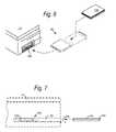
- FIG. 6is a perspective view showing an adapter according to the present invention and a memory card for use therewith adjacent an ExpressCard slot of a host computing device.
- FIG. 7is side cross-sectional view of an ExpressCard slot within a host computing device including an adapter according to embodiments of the present invention.
- FIG. 8is a top view of a memory card according to embodiments of the present invention for use with an ExpressCard slot.
- FIG. 9is an end view of a memory card according to embodiments of the present invention for use with an ExpressCard slot.
- FIGS. 2 through 9relate to an adapter for a memory card slot and a method of configuring a memory card slot.
- the present inventionmay be embodied in many different forms and should not be construed as being limited to the embodiments set forth herein. Rather, these embodiments are provided so that this disclosure will be thorough and complete and will fully convey the invention to those skilled in the art. Indeed, the invention is intended to cover alternatives, modifications and equivalents of these embodiments, which are included within the scope and spirit of the invention as defined by the appended claims.
- numerous specific detailsare set forth in order to provide a thorough understanding of the present invention. However, it will be clear to those of ordinary skill in the art that the present invention may be practiced without such specific details.
- Adapter assembly 100for use within a standard ExpressCard slot such as shown in prior art FIG. 1 .
- Adapter assembly 100generally includes an adapter 102 , a tongue 104 and a finger grip 106 . Each of these components is explained in greater detail below.
- Adapter 102includes a first interface 110 at a front of the adapter assembly 100 including female electrical connectors for mating with pins within a standard ExpressCard slot.
- interface 110will be configured to receive the standard, 26 pin, beam-on blade style connector used in the ExpressCard slot.
- the adapter assembly 100may be used in other types of card slots which may include other types of interface connectors at a front of the adapter in alternative embodiments.
- Adapter 102further includes an interface 112 at a back of the adapter 102 including male connectors for mating with and electrically coupling to one of a variety of memory card formats.
- interface 112may be configured to mate with a memory card 130 explained hereinafter, having dimensions of 45 mm long, 34 mm wide and 4 mm thick.
- interface 112may employ a standard connector, such as the connector used in the ExpressCard slot used for 5 mm thick memory cards, but which has been modified to be thinner so as to operate with a 4 mm thick card.
- the interface 112may resemble a standard 5 mm connector in all other respects, such as the number and type of pin contacts and the contact force established by the pin contacts.
- the adapter assembly 100may operate with memory cards other than memory card 130 , such as for example a CompactFlash memory card, a Secure Digital memory card, or a variety of other standard cards.
- interface 112may be a standard connector for interfacing with these cards.
- Adapter 102further includes a housing 114 extending between interfaces 110 and 112 .
- Housing 114may have a length of approximately 30 mm, a width standard for ExpressCard slots of 34 mm, and a height standard for ExpressCard slots of 5 mm. The length of housing 114 may vary in alternative embodiments and the width and height may vary to match any change in the ExpressCard slot standard.
- Housing 114may have an exterior surface formed of metal, or a plastic or other polymer. As seen for example in the end view of FIG. 4 , the interior of housing 114 may be substantially empty except for a plurality of leads connecting respective electrical connections from interface 110 to interface 112 .
- a memory card connected to interface 112may exchange signals with the host device in the same manner as if the memory card were connected directly to the host device.
- Housing 114may further include partial side rails 116 a and 116 b along both edges of housing 114 .
- Partial side rails 116 a , 116 bserve at least four functions. First, side rails 116 a , 116 b mate within channels provided in the ExpressCard slot to provide a sturdy, precision feel to a user inserting the adapter assembly 100 into the card slot and removing assembly 100 from the slot. Side rails 116 a , 116 b may also prevent the assembly 100 from being inserted up-side-down within the ExpressCard slot.
- side rails 116 a and 116 bfrictionally engage the channels within the ExpressCard slot to securely hold adapter assembly 100 within the ExpressCard slot at all times other than intentional removal of adapter assembly 100 .
- the frictional engagement pressure between side rails 116 a and 116 bmay be increased in embodiments to be greater than that between an ExpressCard memory card and the ExpressCard slot.
- side rails 116 a and/or 116 bmay be made wider or thicker than is known in conventional ExpressCard memory cards to thereby increase the frictional engagement.
- one or more bumps or raised sectionsmay be provided along the otherwise uniform side rails 116 a and/or 116 b to increase frictional engagement of rails 116 a , 116 b with the ExpressCard slot.
- a fourth function of side rails 116 a and 116 bis to defeat the ejector mechanisms conventionally provided in all ExpressCard slots.
- conventional ExpressCard slotsinclude either ejector buttons or push-push mechanisms for ejecting ExpressCard memory cards from the slot.
- side rails 116 a , 116 bare configured to disable (i.e., render ineffective) ejector mechanisms provided within an ExpressCard slot.
- side rails 116 a , 116 bare provided with a length sufficient to allow sturdy insertion and removal as well as frictional engagement with the ExpressCard slot, but also terminate short of the front section of adapter 102 .
- side rails 116 a , 116 bextend from a back portion of housing 114 but terminate short of the front end of the adapter 102 .
- Conventional ejector mechanismsoperate by engaging portions of the front of an ExpressCard memory card.
- both side rails 116 a and 116 bterminate before the front of adapter 102 to defeat the ejector mechanism whether it is located on the left or right side of the card slot.
- the side rail on that sidemay terminate short of the front of the adapter, and the side rail on the opposite side may extend all the way to the front of the adapter in alternative embodiments.
- side rails 116 a and 116 bare long enough to ensure a sturdy insertion/removal and frictional engagement of the adapter assembly with the host slot, but are short enough to defeat the ejector mechanism as described above.
- side rails 116 a , 116 bmay have a length from the back of housing 114 of between 20 mm and 10 mm, and in further embodiments, between 18 mm and 15 mm. It is understood that the length of side rails 116 a and 116 b may be shorter or longer than the ranges set forth above in alternative embodiments, as long as they fulfill the above-described objectives for side rails 116 a and 116 b.
- Tongue 104may be integrally formed or otherwise attached to adapter 102 .
- the tongue 104may be formed of a rigid material such as for example metal, plastic or other polymer, and may be the same material as or different from the material of housing 114 .
- tongue 104may have a length of 45 mm so as to extend from adapter 102 to the front opening of the ExpressCard slot.
- the adapter 102 and tongue 104together extend the entire 75 mm length of a standard ExpressCard slot.
- the width of tongue 104may be the width of the ExpressCard slot, e.g., 34 mm. It is understood that the width of tongue 104 need not extend across the entire width of the ExpressCard slot and maybe less than 34 mm in further embodiments.
- the thickness of tongue 104may for example be 1 mm. As explained hereinafter, a memory card 130 is received within the ExpressCard slot on top of tongue 104 . Accordingly, the combined thickness of tongue 104 and the memory card 130 must be less than or equal to the height of an ExpressCard slot, e.g., 5 mm. In embodiments where a memory card is provided having a thickness less than 4 mm, the thickness of tongue 104 may be greater than 1 mm. Alternatively, it is understood that tongue 104 may be thinner than 1 mm in alternative embodiments, with the provision that tongue 104 have sufficient rigidity to transmit an insertion force exerted on grip 106 as explained below.
- the tongue 104is provided beneath the memory card 130 .
- the tonguemay be configured to cover two, three or all four sides of a memory card and be used within an ExpressCard slot.
- tongue 104may be a continuation of the housing 114 and the two may extend the full length of the ExpressCard slot.
- a back end of tongue 104may have an opening for receiving a memory card.
- Such a memory cardmay be inserted into the tongue and engage with interface 112 as described above.
- Adapter assembly 100may be inserted into an ExpressCard slot one of two ways.
- a first insertion configurationthe adapter assembly 100 may be inserted into an ExpressCard slot without a memory card affixed thereto.
- a userslides the front end of the adapter assembly 100 into the ExpressCard slot, and then pushes on finger grip 106 to bring interface 110 into full engagement with the connector pins within the ExpressCard slot.
- tongue 104must have sufficient rigidity to translate the insertion force exerted on grip 106 to the front interface 110 without buckling.
- a memory cardmay be affixed onto adapter assembly 100 by seating male connectors of interface 112 within the female connectors of the memory card 130 .
- the adapter assembly 100 and memory card 130together have a form factor of a conventional ExpressCard memory card.
- the joined adapter assembly and memory cardmay then together be inserted into the ExpressCard slot.
- the rigidity of tongue 104need not be as high in the second insertion configuration as compared to the rigidity of the tongue 104 necessary in the first insertion configuration.
- the memory cardmay largely prevent buckling of the tongue 104 .
- embodiments of the inventionmay include a tongue having rigidity sufficient to operate with only the second insertion configuration.
- Finger grip 106is affixed to tongue 104 and protrudes from the front opening of the memory card slot when the adapter assembly 100 is fully inserted within the slot. Grip 106 is provided for removal, and, in embodiments, insertion of adapter assembly 100 .
- the adapter assembly 100is a set-it-and-forget-it device which does not get displaced upon insertion or removal of a memory card.
- grip 106may be held by a user to insert adapter assembly 100 into the fully engaged position within the ExpressCard slot.
- Grip 106may be formed to various sizes and of various materials, including for example rubber, metal, plastic or other polymers. In embodiments, grip 106 will have an upper surface level with an upper surface of tongue 104 so that grip 106 does not interfere with a memory card being coupled to adapter assembly 100 . When adapter assembly 100 is in use, grip 106 is the only portion of the assembly protruding from the ExpressCard slot. Grip 106 may include a brand or other marking which is visible while the adapter assembly is fully inserted within the ExpressCard slot.
- FIG. 6is a perspective view showing an adapter assembly 100 positioned adjacent to a slot 120 of a host device 122 , which may for example be a notebook computer, a desktop computer or other computing device that may include an ExpressCard slot.
- FIG. 6further shows a memory card 130 adjacent adapter assembly 100 .
- the adapter assembly 100may be inserted by itself into slot 120 , and thereafter the card 130 inserted into the slot.
- memory card 130may first be joined to adapter assembly 100 , and then the adapter assembly 100 and memory card 130 inserted together into ExpressCard slot 120 .
- FIG. 7shows a cross-sectional side view of host device 122 with the adapter assembly 100 seated within the ExpressCard slot 120 .
- adapter assembly 100effectively converts an ExpressCard slot into a slot capable of operating with memory cards of shorter length than conventional ExpressCard memory cards.
- adapter 102has a length of 30 mm and memory card 130 has a length of 45 mm.
- the respective lengths of adapter 102 and memory card 130may vary, but together they equal the length of slot 120 e.g., 75 mm.
- the combined length of the adapter assembly 100 and card 130may be less than or greater than 75 mm.
- Memory card 130may include a lip 132 at its rear edge serving at least two functions.
- a first functionis to prevent a memory card 130 from being inserted into slot 120 in the absence of an adapter assembly 100 .
- memory card 130has a smaller length and height than ExpressCard slot 120 . If memory card 130 were allowed to be inserted into the slot in the absence of adapter assembly 100 , the card may get lost within the slot.
- lip 132With a height at least as great as the height of the ExpressCard slot 120 , e.g., greater than 5 mm, the lip prevents memory card 130 from getting lost within slot 120 .
- a second function of lip 132is to provide a grip for a user to pull card 130 out of slot 120 .
- a push-push mechanism as described above or otherwisemay be mounted to a side portion of housing 114 , such as for example as part of, or within, one of side rails 116 a or 116 b .
- the memory card 130may be locked within and ejected from slot 120 by the push-push mechanism while the adapter assembly 100 remains in a fixed position within slot 120 .
- a frictional engagement force between side rails 116 a and 116 b and the respective channels in slot 120is greater than the frictional engagement force between the connectors of interface 112 and the female connector of memory card 130 . Accordingly, when card 130 is pulled out, adapter assembly 100 remains securely within its affixed position in ExpressCard slot 120 .
- a locking mechanismas is known in the art may be included as part of, or to operate with, adapter assembly 100 to lock the adapter assembly 100 within the ExpressCard slot 120 .
- Embodiments of the present inventionfurther relate to a memory card resembling a CompactFlash card, but which is compatible with an ExpressCard slot.
- the memory cardin embodiments may be 45 mm long, 34 mm wide and 4 mm thick.
- the memory cardmay work within the ExpressCard slot as would other conventional ExpressCard memory cards.
- the memory cardhas dimensions which are approximately the same as a conventional CompactFlash card.
- users accustomed to the size, look and feel of a conventional CompactFlash cardmay still use a card of approximately that size in their digital cameras, video cameras or other devices, while at the same time availing themselves of the advantages that the ExpressCard interface has to offer.
- memory card 130may include side rails 136 which prevent memory card 130 from being inserted up-side-down within slot 120 .
- Memory card 130may further include an LED 138 for indicating when data transfer is occurring to and from memory card 130 .
- Embodiments of the present inventionthus provide compatibility with the ExpressCard standard and the look and feel of a CompactFlash card.
- the adapter assembly and memory card of the present inventionmay operate according to standards other than the ExpressCard standard.
- the adapter assemblymay allow compatibility between a memory card slot and non-specified memory cards (i.e., memory cards not specified for use with that memory card slot) of various sizes.
Landscapes
- Engineering & Computer Science (AREA)
- Computer Hardware Design (AREA)
- Microelectronics & Electronic Packaging (AREA)
- Physics & Mathematics (AREA)
- General Physics & Mathematics (AREA)
- Theoretical Computer Science (AREA)
- Coupling Device And Connection With Printed Circuit (AREA)
Abstract
Description
Claims (8)
Priority Applications (1)
| Application Number | Priority Date | Filing Date | Title |
|---|---|---|---|
| US11/771,763US8561295B2 (en) | 2007-06-29 | 2007-06-29 | Method of adapting an expresscard slot for smaller form factor memory compatibility |
Applications Claiming Priority (1)
| Application Number | Priority Date | Filing Date | Title |
|---|---|---|---|
| US11/771,763US8561295B2 (en) | 2007-06-29 | 2007-06-29 | Method of adapting an expresscard slot for smaller form factor memory compatibility |
Publications (2)
| Publication Number | Publication Date |
|---|---|
| US20090006682A1 US20090006682A1 (en) | 2009-01-01 |
| US8561295B2true US8561295B2 (en) | 2013-10-22 |
Family
ID=40162066
Family Applications (1)
| Application Number | Title | Priority Date | Filing Date |
|---|---|---|---|
| US11/771,763Active2032-02-09US8561295B2 (en) | 2007-06-29 | 2007-06-29 | Method of adapting an expresscard slot for smaller form factor memory compatibility |
Country Status (1)
| Country | Link |
|---|---|
| US (1) | US8561295B2 (en) |
Cited By (2)
| Publication number | Priority date | Publication date | Assignee | Title |
|---|---|---|---|---|
| US20140301032A1 (en)* | 2013-04-05 | 2014-10-09 | Pny Technologies, Inc. | Reduced Length Memory Card |
| US20160064882A1 (en)* | 2014-08-29 | 2016-03-03 | Golden Vast Macao Commercial Offshore Limited | Detachable Storage Device |
Families Citing this family (5)
| Publication number | Priority date | Publication date | Assignee | Title |
|---|---|---|---|---|
| US7686654B2 (en)* | 2007-06-29 | 2010-03-30 | Sandisk Corporation | Memory card for an ExpressCard slot |
| JP4438846B2 (en)* | 2007-09-14 | 2010-03-24 | ソニー株式会社 | Card type peripheral device |
| US8550858B2 (en)* | 2010-04-07 | 2013-10-08 | Apple Inc. | Extensible memory card-compatible receptacle and port expansion device |
| USD733145S1 (en)* | 2014-03-14 | 2015-06-30 | Kingston Digital, Inc. | Memory module |
| USD735201S1 (en)* | 2014-07-30 | 2015-07-28 | Kingston Digital, Inc. | Memory module |
Citations (63)
| Publication number | Priority date | Publication date | Assignee | Title |
|---|---|---|---|---|
| US5514862A (en) | 1994-05-20 | 1996-05-07 | At&T Corp. | Portable data carrier |
| US5581127A (en) | 1993-06-30 | 1996-12-03 | Mitsubishi Denki Kabushiki Kaisha | IC memory card, host device and connecting system of IC memory card and host device |
| WO1997044867A1 (en) | 1996-05-24 | 1997-11-27 | Itt Manufacturing Enterprises, Inc. | Smart card computer adaptor |
| US5905253A (en) | 1994-09-22 | 1999-05-18 | Yamaichi Electronics Co., Ltd. | Memory card |
| US6101372A (en) | 1997-06-03 | 2000-08-08 | Fujitsu Limited | Portable telephone set |
| US6179665B1 (en) | 1998-08-27 | 2001-01-30 | Curtis Computer Products, Inc. | Multi-function outlet strip having cable organizing features |
| US6234844B1 (en) | 2000-06-28 | 2001-05-22 | Berg Technology, Inc. | Electronic card connector |
| US6264506B1 (en) | 1999-04-23 | 2001-07-24 | J.S.T. Mfg. Co., Ltd. | Card connection adapter |
| US20020002061A1 (en) | 2000-05-26 | 2002-01-03 | Kabushiki Kaisha Toshiba | Electronic apparatus |
| US6402558B1 (en) | 2001-03-13 | 2002-06-11 | Ritek Corporation | Memory card adapter |
| US20020076954A1 (en) | 2000-12-14 | 2002-06-20 | Kuan-Ming Chen | Personal computer card having receptacle for mounting therein micro card |
| US6438638B1 (en) | 2000-07-06 | 2002-08-20 | Onspec Electronic, Inc. | Flashtoaster for reading several types of flash-memory cards with or without a PC |
| US6567273B1 (en) | 2002-02-06 | 2003-05-20 | Carry Computer Eng. Co., Ltd. | Small silicon disk card with a USB plug |
| US6574112B2 (en) | 2000-01-24 | 2003-06-03 | J. S. T. Mfg. Co., Ltd. | Card connecting adapter and IC card with antenna |
| US20030201322A1 (en) | 2002-04-29 | 2003-10-30 | Mei-Ching Wu | Adapter of compact flash memory card for various types of flash memory card |
| US6692268B2 (en) | 2002-05-14 | 2004-02-17 | I/O Interconnect Inc. | PC card |
| US6725286B2 (en) | 2000-08-31 | 2004-04-20 | Sony Corporation | Information-processing apparatus, information-processing method, memory card and program storage medium |
| US20040087213A1 (en) | 2002-08-16 | 2004-05-06 | Chi-Lei Kao | Plug used for connection with a usb receptacle |
| US6736678B2 (en) | 2002-06-26 | 2004-05-18 | Li-Ho Yao | Memory card interface adapter |
| US6751694B2 (en) | 2001-08-29 | 2004-06-15 | Carry Computer Eng. Co., Ltd. | Silicon disk drive with few slots for plural disks |
| US6768644B2 (en) | 2001-05-29 | 2004-07-27 | Murata Manufacturing Co., Ltd. | Compact flash card |
| US6808424B2 (en) | 2000-04-18 | 2004-10-26 | Matsushita Electric Industrial Co., Ltd. | Memory card installer |
| US6859369B2 (en) | 2000-07-06 | 2005-02-22 | Onspec Electronic Inc. | Smartuniversal flash media card adapters |
| US20050048833A1 (en) | 2003-09-03 | 2005-03-03 | Japan Aviation Electronics Industry, Limited | Card fitting mechanism having a plurality of card receiving portions and yet capable of being reduced in size |
| US20050066102A1 (en) | 2003-03-31 | 2005-03-24 | Hitoshi Yamamoto | Method and apparatus for controlling connections of PC cards and a passive-card-adapting card used for connecting one of the PC cards to the apparatus |
| US20050114587A1 (en) | 2003-11-22 | 2005-05-26 | Super Talent Electronics Inc. | ExpressCard with On-Card Flash Memory with Shared Flash-Control Bus but Separate Ready Lines |
| US6908038B1 (en) | 2004-02-27 | 2005-06-21 | Imotion Corp. | Multi-connector memory card with retractable sheath to protect the connectors |
| JP2005196247A (en) | 2003-12-26 | 2005-07-21 | Murata Mfg Co Ltd | Pc card with cover |
| EP1587020A1 (en) | 2004-04-14 | 2005-10-19 | AboCom Systems, Inc. | Adapter for interface card |
| US20050251609A1 (en) | 2004-05-04 | 2005-11-10 | Horng-Yee Chou | Removable peripheral device |
| WO2005106781A1 (en) | 2004-04-16 | 2005-11-10 | Sandisk Corporation | Memory cards having two standard sets of contacts |
| US20050258243A1 (en) | 2003-11-14 | 2005-11-24 | Hsiang-An Hsieh | Express card interface adapter for small storage media |
| US6976624B2 (en) | 2003-09-05 | 2005-12-20 | Wem Technology Inc. | 7-in-1 card reader for PCMCIA interface |
| US6993618B2 (en) | 2004-01-15 | 2006-01-31 | Super Talent Electronics, Inc. | Dual-mode flash storage exchanger that transfers flash-card data to a removable USB flash key-drive with or without a PC host |
| US7044767B2 (en) | 2004-06-29 | 2006-05-16 | Intel Corporation | Hybrid card interconnect |
| US7059913B1 (en) | 2005-05-31 | 2006-06-13 | D & C Technology Co., Ltd. | Express card adapter card |
| TWM292823U (en) | 2005-12-22 | 2006-06-21 | Cheng Uei Prec Ind Co Ltd | Push-pull SIM card connector |
| US7075793B2 (en) | 2001-11-19 | 2006-07-11 | Imation Corp. | Device having a slot capable of receiving at least four types of memory cards |
| US7092256B1 (en) | 2002-04-26 | 2006-08-15 | Sandisk Corporation | Retractable card adapter |
| US7108557B2 (en) | 2004-03-18 | 2006-09-19 | Yamaichi Electronics Co., Ltd. | Integrated circuit (IC) card connector including a movable braking piece |
| US7112075B1 (en) | 2006-02-08 | 2006-09-26 | Cheng Uei Precision Industry Co., Ltd. | Drawer SIM card connector |
| US7125258B2 (en) | 2003-03-31 | 2006-10-24 | Fujitsu Limited | Card-type terminal |
| US7172430B2 (en) | 2001-08-31 | 2007-02-06 | Molex Incorporated | Memory card connector with ESD protection and card locking device |
| US7182645B2 (en) | 2004-01-23 | 2007-02-27 | Yamaichi Electronics Co., Ltd. | Card connector for an electronic device and a contact used therein |
| US7217150B2 (en) | 2004-11-25 | 2007-05-15 | Yazaki Europe Ltd. | Connector arrangement with staggered mating |
| US7265989B2 (en) | 2003-04-08 | 2007-09-04 | Softbank Bb Corp. | PC card |
| US7281953B1 (en) | 2005-08-05 | 2007-10-16 | Unisys Corporation | Computer card adapter |
| US7300314B2 (en) | 2004-10-12 | 2007-11-27 | Samsung Electronics Co., Ltd. | Socket for trans-flash memory card |
| US7306467B2 (en) | 2005-01-07 | 2007-12-11 | Lenovo (Singapore) Pte. Ltd. | Slot device |
| US7326086B1 (en) | 2007-02-02 | 2008-02-05 | Yun-Hsiu Lee | Card adapter structure |
| US7341461B1 (en) | 2006-09-18 | 2008-03-11 | Chant Sincere Co., Ltd. | Memory card adapter |
| US7354312B2 (en) | 2006-01-23 | 2008-04-08 | A-Data Technology Co., Ltd. | Slim card reader |
| US7367511B2 (en) | 2005-06-08 | 2008-05-06 | Sony Ericsson Mobile Communication Ab | Interface card design and method of manufacture |
| US20080123274A1 (en) | 2006-11-28 | 2008-05-29 | Desrosiers Norman B | Cartridge for space-restricted installation in rack-mounted computer system |
| US7382625B2 (en) | 2006-01-23 | 2008-06-03 | Sony Ericsson Mobile Communications Ab | Combination antenna and SIM card support structure |
| US7385827B2 (en) | 2004-01-09 | 2008-06-10 | Stocko Contact Gmbh & Co. Kg | Contacting unit for a card-type carrier element in electronic component groups |
| US20080168204A1 (en) | 2007-01-04 | 2008-07-10 | Dell Products L.P. | Information Handling System Card |
| US7416451B2 (en) | 2006-12-15 | 2008-08-26 | Hosiden Corporation | Card adapter |
| US20080228986A1 (en) | 2007-03-12 | 2008-09-18 | Luca Lodolo | Architecture for controlling peripheral devices |
| US20080270663A1 (en) | 2007-04-30 | 2008-10-30 | Fry Walter G | Computer card |
| US7460076B2 (en) | 2006-06-13 | 2008-12-02 | Sony Ericsson Mobile Communications Ab | Mobile wireless communications terminals and wireless communications cards for use with an electronic device |
| US7475816B1 (en) | 2004-06-03 | 2009-01-13 | Rochelo Donald R | Protective case for a plurality of different sized memory cards |
| US7534116B2 (en) | 2004-05-12 | 2009-05-19 | Molex Incorporated | Eject mechanism for memory card connector |
- 2007
- 2007-06-29USUS11/771,763patent/US8561295B2/enactiveActive
Patent Citations (64)
| Publication number | Priority date | Publication date | Assignee | Title |
|---|---|---|---|---|
| US5581127A (en) | 1993-06-30 | 1996-12-03 | Mitsubishi Denki Kabushiki Kaisha | IC memory card, host device and connecting system of IC memory card and host device |
| US5514862A (en) | 1994-05-20 | 1996-05-07 | At&T Corp. | Portable data carrier |
| US5905253A (en) | 1994-09-22 | 1999-05-18 | Yamaichi Electronics Co., Ltd. | Memory card |
| WO1997044867A1 (en) | 1996-05-24 | 1997-11-27 | Itt Manufacturing Enterprises, Inc. | Smart card computer adaptor |
| US6101372A (en) | 1997-06-03 | 2000-08-08 | Fujitsu Limited | Portable telephone set |
| US6179665B1 (en) | 1998-08-27 | 2001-01-30 | Curtis Computer Products, Inc. | Multi-function outlet strip having cable organizing features |
| US6264506B1 (en) | 1999-04-23 | 2001-07-24 | J.S.T. Mfg. Co., Ltd. | Card connection adapter |
| US6574112B2 (en) | 2000-01-24 | 2003-06-03 | J. S. T. Mfg. Co., Ltd. | Card connecting adapter and IC card with antenna |
| US6808424B2 (en) | 2000-04-18 | 2004-10-26 | Matsushita Electric Industrial Co., Ltd. | Memory card installer |
| US20020002061A1 (en) | 2000-05-26 | 2002-01-03 | Kabushiki Kaisha Toshiba | Electronic apparatus |
| US6234844B1 (en) | 2000-06-28 | 2001-05-22 | Berg Technology, Inc. | Electronic card connector |
| US6859369B2 (en) | 2000-07-06 | 2005-02-22 | Onspec Electronic Inc. | Smartuniversal flash media card adapters |
| US6438638B1 (en) | 2000-07-06 | 2002-08-20 | Onspec Electronic, Inc. | Flashtoaster for reading several types of flash-memory cards with or without a PC |
| US6725286B2 (en) | 2000-08-31 | 2004-04-20 | Sony Corporation | Information-processing apparatus, information-processing method, memory card and program storage medium |
| US20020076954A1 (en) | 2000-12-14 | 2002-06-20 | Kuan-Ming Chen | Personal computer card having receptacle for mounting therein micro card |
| US6402558B1 (en) | 2001-03-13 | 2002-06-11 | Ritek Corporation | Memory card adapter |
| US6768644B2 (en) | 2001-05-29 | 2004-07-27 | Murata Manufacturing Co., Ltd. | Compact flash card |
| US6751694B2 (en) | 2001-08-29 | 2004-06-15 | Carry Computer Eng. Co., Ltd. | Silicon disk drive with few slots for plural disks |
| US7172430B2 (en) | 2001-08-31 | 2007-02-06 | Molex Incorporated | Memory card connector with ESD protection and card locking device |
| US7075793B2 (en) | 2001-11-19 | 2006-07-11 | Imation Corp. | Device having a slot capable of receiving at least four types of memory cards |
| US6567273B1 (en) | 2002-02-06 | 2003-05-20 | Carry Computer Eng. Co., Ltd. | Small silicon disk card with a USB plug |
| US7092256B1 (en) | 2002-04-26 | 2006-08-15 | Sandisk Corporation | Retractable card adapter |
| US20030201322A1 (en) | 2002-04-29 | 2003-10-30 | Mei-Ching Wu | Adapter of compact flash memory card for various types of flash memory card |
| US6692268B2 (en) | 2002-05-14 | 2004-02-17 | I/O Interconnect Inc. | PC card |
| US6736678B2 (en) | 2002-06-26 | 2004-05-18 | Li-Ho Yao | Memory card interface adapter |
| US20040087213A1 (en) | 2002-08-16 | 2004-05-06 | Chi-Lei Kao | Plug used for connection with a usb receptacle |
| US20050066102A1 (en) | 2003-03-31 | 2005-03-24 | Hitoshi Yamamoto | Method and apparatus for controlling connections of PC cards and a passive-card-adapting card used for connecting one of the PC cards to the apparatus |
| US7125258B2 (en) | 2003-03-31 | 2006-10-24 | Fujitsu Limited | Card-type terminal |
| US7265989B2 (en) | 2003-04-08 | 2007-09-04 | Softbank Bb Corp. | PC card |
| US7108530B2 (en) | 2003-09-03 | 2006-09-19 | Japan Aviation Electronics Industry, Limited | Card fitting mechanism having a plurality of card receiving portions and yet capable of being reduced in size |
| US20050048833A1 (en) | 2003-09-03 | 2005-03-03 | Japan Aviation Electronics Industry, Limited | Card fitting mechanism having a plurality of card receiving portions and yet capable of being reduced in size |
| US6976624B2 (en) | 2003-09-05 | 2005-12-20 | Wem Technology Inc. | 7-in-1 card reader for PCMCIA interface |
| US20050258243A1 (en) | 2003-11-14 | 2005-11-24 | Hsiang-An Hsieh | Express card interface adapter for small storage media |
| US20050114587A1 (en) | 2003-11-22 | 2005-05-26 | Super Talent Electronics Inc. | ExpressCard with On-Card Flash Memory with Shared Flash-Control Bus but Separate Ready Lines |
| JP2005196247A (en) | 2003-12-26 | 2005-07-21 | Murata Mfg Co Ltd | Pc card with cover |
| US7385827B2 (en) | 2004-01-09 | 2008-06-10 | Stocko Contact Gmbh & Co. Kg | Contacting unit for a card-type carrier element in electronic component groups |
| US6993618B2 (en) | 2004-01-15 | 2006-01-31 | Super Talent Electronics, Inc. | Dual-mode flash storage exchanger that transfers flash-card data to a removable USB flash key-drive with or without a PC host |
| US7182645B2 (en) | 2004-01-23 | 2007-02-27 | Yamaichi Electronics Co., Ltd. | Card connector for an electronic device and a contact used therein |
| US6908038B1 (en) | 2004-02-27 | 2005-06-21 | Imotion Corp. | Multi-connector memory card with retractable sheath to protect the connectors |
| US7108557B2 (en) | 2004-03-18 | 2006-09-19 | Yamaichi Electronics Co., Ltd. | Integrated circuit (IC) card connector including a movable braking piece |
| EP1587020A1 (en) | 2004-04-14 | 2005-10-19 | AboCom Systems, Inc. | Adapter for interface card |
| WO2005106781A1 (en) | 2004-04-16 | 2005-11-10 | Sandisk Corporation | Memory cards having two standard sets of contacts |
| US20050251609A1 (en) | 2004-05-04 | 2005-11-10 | Horng-Yee Chou | Removable peripheral device |
| US7534116B2 (en) | 2004-05-12 | 2009-05-19 | Molex Incorporated | Eject mechanism for memory card connector |
| US7475816B1 (en) | 2004-06-03 | 2009-01-13 | Rochelo Donald R | Protective case for a plurality of different sized memory cards |
| US7044767B2 (en) | 2004-06-29 | 2006-05-16 | Intel Corporation | Hybrid card interconnect |
| US7300314B2 (en) | 2004-10-12 | 2007-11-27 | Samsung Electronics Co., Ltd. | Socket for trans-flash memory card |
| US7217150B2 (en) | 2004-11-25 | 2007-05-15 | Yazaki Europe Ltd. | Connector arrangement with staggered mating |
| US7306467B2 (en) | 2005-01-07 | 2007-12-11 | Lenovo (Singapore) Pte. Ltd. | Slot device |
| US7059913B1 (en) | 2005-05-31 | 2006-06-13 | D & C Technology Co., Ltd. | Express card adapter card |
| US7367511B2 (en) | 2005-06-08 | 2008-05-06 | Sony Ericsson Mobile Communication Ab | Interface card design and method of manufacture |
| US7281953B1 (en) | 2005-08-05 | 2007-10-16 | Unisys Corporation | Computer card adapter |
| TWM292823U (en) | 2005-12-22 | 2006-06-21 | Cheng Uei Prec Ind Co Ltd | Push-pull SIM card connector |
| US7354312B2 (en) | 2006-01-23 | 2008-04-08 | A-Data Technology Co., Ltd. | Slim card reader |
| US7382625B2 (en) | 2006-01-23 | 2008-06-03 | Sony Ericsson Mobile Communications Ab | Combination antenna and SIM card support structure |
| US7112075B1 (en) | 2006-02-08 | 2006-09-26 | Cheng Uei Precision Industry Co., Ltd. | Drawer SIM card connector |
| US7460076B2 (en) | 2006-06-13 | 2008-12-02 | Sony Ericsson Mobile Communications Ab | Mobile wireless communications terminals and wireless communications cards for use with an electronic device |
| US7341461B1 (en) | 2006-09-18 | 2008-03-11 | Chant Sincere Co., Ltd. | Memory card adapter |
| US20080123274A1 (en) | 2006-11-28 | 2008-05-29 | Desrosiers Norman B | Cartridge for space-restricted installation in rack-mounted computer system |
| US7416451B2 (en) | 2006-12-15 | 2008-08-26 | Hosiden Corporation | Card adapter |
| US20080168204A1 (en) | 2007-01-04 | 2008-07-10 | Dell Products L.P. | Information Handling System Card |
| US7326086B1 (en) | 2007-02-02 | 2008-02-05 | Yun-Hsiu Lee | Card adapter structure |
| US20080228986A1 (en) | 2007-03-12 | 2008-09-18 | Luca Lodolo | Architecture for controlling peripheral devices |
| US20080270663A1 (en) | 2007-04-30 | 2008-10-30 | Fry Walter G | Computer card |
Non-Patent Citations (74)
| Title |
|---|
| Amendment filed Feb. 17, 2009 in U.S. Appl. No. 11/771,730. |
| Decision dated Apr. 26, 2011, Taiwanese Patent Application No. 097100466. |
| English translation of Abstract and Specification of JP2005196247 published on Jul. 21, 2005. |
| English Translation of Request for Re-Examination and amended claims filed Nov. 1, 2011 in Taiwanese Patent Application No. 097100466. |
| Final Office Action dated Aug. 7, 2008 in U.S. Appl. No. 11/620,530. |
| Final Office Action dated Nov. 21, 2008 in U.S. Appl. No. 11/771,717. |
| International Search Report and Written Opinion dated Dec. 16, 2008 in PCT Application No. PCT/US2008/068531. |
| International Search Report and Written Opinion dated Jul. 3, 2008 in PCT Application No. PCT/US2007/089069. |
| Notice of Allowance and Fee(s) Due dated Dec. 3, 2009 in U.S. Appl. No. 11/771,767. |
| Notice of Allowance and Fee(s) due dated Feb. 1, 2010 in U.S. Appl. No. 12/103,533. |
| Notice of Allowance and Fee(s) Due dated Jun. 17, 2009 in U.S. Appl. No. 11/771,730. |
| Notice of Allowance and Fee(s) Due dated Oct. 1, 2009 in U.S. Appl. No. 11/771,756. |
| Notice of Allowance and Fee(s) Due dated Oct. 19, 2009 in U.S. Appl. No. 11/771,767. |
| Notice of Allowance and Fee(s) Due dated Oct. 26, 2009 in U.S. Appl. No. 11/771,756. |
| Notice of Allowance and Fee(s) Due dated Sep. 12, 2011, U.S. Appl. No. 12/727,519. |
| Notice of Allowance and Fee(s) Due Oct. 1, 2009 in U.S. Appl. No. 11/771,730. |
| Notice of Allowance and feee(s) Due dated Apr. 23, 2010, U.S. Appl. No. 11/771,744. |
| Notice of Allowance dated Aug. 17, 2011, U.S. Appl. No. 11/771,752. |
| Notice of Allowance dated Nov. 14, 2008 in U.S. Appl. No. 11/771,730. |
| Office Action dated Apr. 1, 2009 in U.S. Appl. No. 11/771,744. |
| Office Action dated Apr. 21, 2010, U.S. Appl. No. 11/771,752. |
| Office Action dated Aug. 17, 2011 in Chinese Patent Application No. 200880022599.1. |
| Office Action dated Dec. 11, 2008 in U.S. Appl. No. 11/771,756. |
| Office Action dated Dec. 24, 2010, Taiwanese Patent Application No. 097100466. |
| Office Action dated Dec. 29, 2008 in U.S. Appl. No. 12/103,533. |
| Office Action dated Feb. 16, 2012 in Chinese Patent Application No. 200780049352.4. |
| Office Action dated Feb. 22, 2012 in Taiwanese Patent Application No. 097124425. |
| Office Action dated Feb. 24, 2011 in Chinese Patent Application No. 200780049352.4. |
| Office Action dated Feb. 8, 2011 in Korean Patent Application No. 7015216/2009. |
| Office Action dated Jan. 6, 2010 in U.S. Appl. No. 11/620,519. |
| Office Action dated Jan. 8, 2009 in U.S. Appl. No. 11/620,519. |
| Office Action dated Jul. 10, 2009 in U.S. Appl. No. 12/103,533. |
| Office Action dated Jul. 7, 2009 in U.S. Appl. No. 11/620,519. |
| Office Action dated Jul. 7, 2009 in U.S. Appl. No. 11/771,767. |
| Office Action dated Jul. 9, 2008 in U.S. Appl. No. 11/620,519. |
| Office Action dated Mar. 21, 2011, U.S. Appl. No. 12/727,519. |
| Office Action dated May 13, 2008, U.S. Appl. No. 11/771,717, filed Jun. 29, 2007. |
| Office Action dated May 27, 2009 in U.S. Appl. No. 11/771,756. |
| Office Action dated Oct. 22, 2009 in U.S. Appl. No. 11/771,752. |
| Office Action dated Sep. 2, 2009 in U.S. Appl. No. 11/771,744. |
| Office Action mailed Dec. 28, 2007 in U.S. Appl. No. 11/620,530, filed Jan. 5, 2007. |
| Office Action mailed Jan. 14, 2008 in U.S. Appl. No. 11/620,519 filed Jan. 5, 2007. |
| Office Action mailed Nov. 17, 2013, U.S. Appl. No. 11/771,752. |
| Partial Translation of TVVM292823 published Jun. 21, 2006. |
| Re-examination Brief filed Jun. 28, 2013 in Taiwanese Patent Application No. 097124425. |
| Rejection Decision dated Jun. 26, 2012 in Chinese Patent Application No. 200880022599.1. |
| Request for Re-Examination filed Nov. 1, 2011 in Taiwanese Patent Application No. 097100466. |
| Response to Ofcice Action filed Aug. 3, 2009 in U.S. Appl. No. 11/771,767. |
| Response to Office Action dated Apr. 25, 2008, U.S. Appl. No. 11/620,530, filed Jan. 5, 2007. |
| Response to Office Action dated Feb. 14, 2008 in U.S. Appl. No. 11/620,519, filed Jan. 5, 2007. |
| Response to Office Action dated Sep. 30, 2008 in U.S. Appl. No. 11/620,519. |
| Response to Office Action filed Apr. 8, 2009 in U.S. Appl. No. 11/620,159. |
| Response to Office Action filed Dec. 2, 2009 in U.S. Appl. No. 11/771,744. |
| Response to Office Action filed Jul. 21, 2011, U.S. Appl. No. 12/727,519. |
| Response to Office Action filed Jul. 8, 2011 in Korean Patent Application No. 7015216/2209. |
| Response to Office Action filed Jun. 24, 2011 in Chinese Patent Application No. 2007800493.4. |
| Response to Office Action filed Jun. 25, 2009 in U.S. Appl. No. 11/771,744. |
| Response to Office Action filed Jun. 30, 2009 in U.S. Appl. No. 11/771,756. |
| Response to Office Action filed Mar. 28, 2011, Taiwanese Patent Application No. 097100466. |
| Response to Office Action filed Mar. 30, 2009 in U.S. Appl. No. 12/103,533. |
| Response to Office Action filed May 17, 2011, U.S. Appl. No. 11,771,752. |
| Response to Office Action filed May 2, 2012 in Chinese Patent Application No. 20078004935.4. |
| Response to Office Action filed Oct. 13, 2009 in U.S. Appl. No. 12/103,533. |
| Response to Office Action filed Oct. 21, 2010, U.S. Appl. No. 11/771,752. |
| Response to Office Action filed Oct. 7, 2009 in U.S. Appl. No. 11/620,519. |
| Response to Ofice Action dated Aug. 13, 2008 in U.S. Appl. No. 11/771,717. |
| U.S. Appl. No. 11/620,519, filed Jan. 5, 2007. |
| U.S. Appl. No. 11/620,530, filed Jan. 5, 2007. |
| U.S. Appl. No. 11/771,717, filed Jun. 29, 2007. |
| U.S. Appl. No. 11/771,744, filed Jun. 29, 2007. |
| U.S. Appl. No. 11/771,752, filed Jun. 29, 2007. |
| U.S. Appl. No. 11/771,756, filed Jun. 29, 2007. |
| U.S. Appl. No. 11/771,767, filed Jun. 29, 2007. |
| U.S. Appl.No. 11/771,730, filed Jun. 29, 2007. |
Cited By (3)
| Publication number | Priority date | Publication date | Assignee | Title |
|---|---|---|---|---|
| US20140301032A1 (en)* | 2013-04-05 | 2014-10-09 | Pny Technologies, Inc. | Reduced Length Memory Card |
| US9442539B2 (en)* | 2013-04-05 | 2016-09-13 | Pny Technologies, Inc. | Reduced length memory card |
| US20160064882A1 (en)* | 2014-08-29 | 2016-03-03 | Golden Vast Macao Commercial Offshore Limited | Detachable Storage Device |
Also Published As
| Publication number | Publication date |
|---|---|
| US20090006682A1 (en) | 2009-01-01 |
Similar Documents
| Publication | Publication Date | Title |
|---|---|---|
| US7686654B2 (en) | Memory card for an ExpressCard slot | |
| US7699660B2 (en) | Adapter for an expresscard slot | |
| US8051229B2 (en) | Dual bus ExpressCard peripheral device | |
| US7779184B2 (en) | Method of using the dual bus interface in an expresscard slot | |
| US7780477B2 (en) | Adapter system for use with an expresscard slot | |
| US8561295B2 (en) | Method of adapting an expresscard slot for smaller form factor memory compatibility | |
| US6792487B2 (en) | Universal serial bus (USB) connector connecting structure for a multi-function device | |
| JP4432202B2 (en) | Card-type recording medium storage case, storage case holder, and electronic device | |
| US6385040B2 (en) | Card-shaped storage medium and information processing apparatus having guide portion for the same | |
| US7223574B2 (en) | Portable memory device with protective cap | |
| US6814597B1 (en) | Subscriber identity module (SIM) card connector with ejector | |
| JP5818366B2 (en) | Card connector | |
| CN201160004Y (en) | mobile storage device | |
| US7762849B2 (en) | Expandable and collapsible peripheral device | |
| US6478591B1 (en) | Card ejection mechanism for electrical card connector | |
| US20090004920A1 (en) | Method of adapting an expresscard slot for use with portable memory cards | |
| US20080166898A1 (en) | Method of making an expandable and collapsible peripheral device | |
| JP4694340B2 (en) | Card connector | |
| US7352601B1 (en) | USB flash memory device | |
| TWI239696B (en) | Electrical connector with module ejection system | |
| US7958297B2 (en) | Card-type peripheral device | |
| US7614891B2 (en) | Card connector | |
| CN104951419B (en) | Dual Bus Express Card Peripherals | |
| US20040174683A1 (en) | Peripheral card and cable plug having the same form factor | |
| CN2684257Y (en) | portable storage device |
Legal Events
| Date | Code | Title | Description |
|---|---|---|---|
| AS | Assignment | Owner name:SANDISK CORPORATION, CALIFORNIA Free format text:ASSIGNMENT OF ASSIGNORS INTEREST;ASSIGNORS:HUBERT, JONATHAN;HANLON, JASON P.;MACDONALD, JORDAN;REEL/FRAME:019696/0185;SIGNING DATES FROM 20070730 TO 20070731 Owner name:SANDISK CORPORATION, CALIFORNIA Free format text:ASSIGNMENT OF ASSIGNORS INTEREST;ASSIGNORS:HUBERT, JONATHAN;HANLON, JASON P.;MACDONALD, JORDAN;SIGNING DATES FROM 20070730 TO 20070731;REEL/FRAME:019696/0185 | |
| AS | Assignment | Owner name:SANDISK TECHNOLOGIES INC., TEXAS Free format text:ASSIGNMENT OF ASSIGNORS INTEREST;ASSIGNOR:SANDISK CORPORATION;REEL/FRAME:026262/0084 Effective date:20110404 | |
| STCF | Information on status: patent grant | Free format text:PATENTED CASE | |
| AS | Assignment | Owner name:SANDISK TECHNOLOGIES LLC, TEXAS Free format text:CHANGE OF NAME;ASSIGNOR:SANDISK TECHNOLOGIES INC;REEL/FRAME:038809/0600 Effective date:20160516 | |
| FPAY | Fee payment | Year of fee payment:4 | |
| MAFP | Maintenance fee payment | Free format text:PAYMENT OF MAINTENANCE FEE, 8TH YEAR, LARGE ENTITY (ORIGINAL EVENT CODE: M1552); ENTITY STATUS OF PATENT OWNER: LARGE ENTITY Year of fee payment:8 | |
| AS | Assignment | Owner name:SANDISK TECHNOLOGIES, INC., CALIFORNIA Free format text:ASSIGNMENT OF ASSIGNORS INTEREST;ASSIGNOR:SANDISK TECHNOLOGIES LLC;REEL/FRAME:069796/0423 Effective date:20241227 | |
| MAFP | Maintenance fee payment | Free format text:PAYMENT OF MAINTENANCE FEE, 12TH YEAR, LARGE ENTITY (ORIGINAL EVENT CODE: M1553); ENTITY STATUS OF PATENT OWNER: LARGE ENTITY Year of fee payment:12 | |
| AS | Assignment | Owner name:SANDISK TECHNOLOGIES, INC., CALIFORNIA Free format text:PARTIAL RELEASE OF SECURITY INTERESTS;ASSIGNOR:JPMORGAN CHASE BANK, N.A., AS AGENT;REEL/FRAME:071382/0001 Effective date:20250424 Owner name:JPMORGAN CHASE BANK, N.A., AS COLLATERAL AGENT, ILLINOIS Free format text:SECURITY AGREEMENT;ASSIGNOR:SANDISK TECHNOLOGIES, INC.;REEL/FRAME:071050/0001 Effective date:20250424 |