US8560035B2 - Physiological sensor with a tail - Google Patents
Physiological sensor with a tailDownload PDFInfo
- Publication number
- US8560035B2 US8560035B2US12/860,444US86044410AUS8560035B2US 8560035 B2US8560035 B2US 8560035B2US 86044410 AUS86044410 AUS 86044410AUS 8560035 B2US8560035 B2US 8560035B2
- Authority
- US
- United States
- Prior art keywords
- sensor
- tail
- layer
- light
- set forth
- Prior art date
- Legal status (The legal status is an assumption and is not a legal conclusion. Google has not performed a legal analysis and makes no representation as to the accuracy of the status listed.)
- Active, expires
Links
Images


Classifications
- A—HUMAN NECESSITIES
- A61—MEDICAL OR VETERINARY SCIENCE; HYGIENE
- A61B—DIAGNOSIS; SURGERY; IDENTIFICATION
- A61B5/00—Measuring for diagnostic purposes; Identification of persons
- A61B5/145—Measuring characteristics of blood in vivo, e.g. gas concentration or pH-value ; Measuring characteristics of body fluids or tissues, e.g. interstitial fluid or cerebral tissue
- A61B5/1455—Measuring characteristics of blood in vivo, e.g. gas concentration or pH-value ; Measuring characteristics of body fluids or tissues, e.g. interstitial fluid or cerebral tissue using optical sensors, e.g. spectral photometrical oximeters
- A61B5/14551—Measuring characteristics of blood in vivo, e.g. gas concentration or pH-value ; Measuring characteristics of body fluids or tissues, e.g. interstitial fluid or cerebral tissue using optical sensors, e.g. spectral photometrical oximeters for measuring blood gases
- A61B5/14552—Details of sensors specially adapted therefor
- A—HUMAN NECESSITIES
- A61—MEDICAL OR VETERINARY SCIENCE; HYGIENE
- A61B—DIAGNOSIS; SURGERY; IDENTIFICATION
- A61B5/00—Measuring for diagnostic purposes; Identification of persons
- A61B5/145—Measuring characteristics of blood in vivo, e.g. gas concentration or pH-value ; Measuring characteristics of body fluids or tissues, e.g. interstitial fluid or cerebral tissue
- A61B5/1455—Measuring characteristics of blood in vivo, e.g. gas concentration or pH-value ; Measuring characteristics of body fluids or tissues, e.g. interstitial fluid or cerebral tissue using optical sensors, e.g. spectral photometrical oximeters
- A61B5/14551—Measuring characteristics of blood in vivo, e.g. gas concentration or pH-value ; Measuring characteristics of body fluids or tissues, e.g. interstitial fluid or cerebral tissue using optical sensors, e.g. spectral photometrical oximeters for measuring blood gases
- A—HUMAN NECESSITIES
- A61—MEDICAL OR VETERINARY SCIENCE; HYGIENE
- A61B—DIAGNOSIS; SURGERY; IDENTIFICATION
- A61B2562/00—Details of sensors; Constructional details of sensor housings or probes; Accessories for sensors
- A61B2562/22—Arrangements of medical sensors with cables or leads; Connectors or couplings specifically adapted for medical sensors
- A61B2562/225—Connectors or couplings
- A61B2562/227—Sensors with electrical connectors
- H—ELECTRICITY
- H01—ELECTRIC ELEMENTS
- H01R—ELECTRICALLY-CONDUCTIVE CONNECTIONS; STRUCTURAL ASSOCIATIONS OF A PLURALITY OF MUTUALLY-INSULATED ELECTRICAL CONNECTING ELEMENTS; COUPLING DEVICES; CURRENT COLLECTORS
- H01R2201/00—Connectors or connections adapted for particular applications
- H01R2201/12—Connectors or connections adapted for particular applications for medicine and surgery
- H—ELECTRICITY
- H01—ELECTRIC ELEMENTS
- H01R—ELECTRICALLY-CONDUCTIVE CONNECTIONS; STRUCTURAL ASSOCIATIONS OF A PLURALITY OF MUTUALLY-INSULATED ELECTRICAL CONNECTING ELEMENTS; COUPLING DEVICES; CURRENT COLLECTORS
- H01R35/00—Flexible or turnable line connectors, i.e. the rotation angle being limited
- H01R35/02—Flexible line connectors without frictional contact members
Definitions
- Near-infrared sensorsare used in the medical industry to measure the amount of oxygen saturation in a patient's blood or tissue.
- a cableis used to connect the sensor to a controller that controls operation of the sensor and receives signals from the sensor.
- patientsmove while wearing the sensor.
- a clinicianmay move the patient (e.g., rotate the patient) during a procedure. This movement could either cause the sensor to disconnect from the cable or cause the patient discomfort due to lying on the cable.
- a near-infrared sensoris needed that allows the patient to be moved or rotated without the risk of disconnecting the sensor from the cable or the discomfort caused by lying on the cable.
- FIG. 1illustrates a sensor having a tail and disposed on a patient.
- FIG. 2illustrates an assembly view of an exemplary sensor having a sensor pad with layers and a circuit board with an integrally formed tail.
- FIG. 3illustrates an assembly view of an exemplary sensor having a sensor pad that includes a spacer and a circuit board with an integrally formed tail.
- FIG. 4illustrates an assembly view of an exemplary sensor having a sensor pad with a bottom layer that forms an overlay disposed on a tail that is integrally formed with a circuit board.
- FIG. 5illustrates an assembly view of an exemplary sensor having a sensor pad with a top layer that forms an overlay disposed on a tail that is integrally formed with a circuit board.
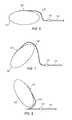
- FIG. 6illustrates an exemplary sensor having a tail and disposed on a patient's body.
- FIG. 7illustrates an exemplary sensor having a tail and disposed on a rotated patient's body.
- FIG. 8illustrates an assembly view of an exemplary sensor having a tail and disposed on a rotated patient such that the patient is lying on the tail.
- the circuit boardhas an integrally formed tail and the sensor pad includes an overlay that is disposed on the tail.
- the tail and overlayhave a thickness that is less than a thickness of the cable. Further, both the tail and overlay are flexible, and the overlay includes a soft, slippery material.
- the tailhas a length that is sufficient so that the sensor will not be disconnected from the cable if the patient is rotated. Moreover, should the patient be rotated to lie on the tail and overlay, the patient will experience a reduced level of discomfort than if the patient were to lie on the cable.
- the sensor padfurther houses a light source configured to generate near-infrared light and a light detector configured to receive near-infrared light.
- the light source and the light detectorare each aligned with one of the openings of the sensor pad so that near-infrared light generated by the light source can travel through a part of a patient's body to the light detector and the near-infrared light received by the light detector indicates oxygen saturation of the part of the patient's body through which the light travelled.
- FIG. 1illustrates an exemplary sensor 100 that allows a patient to be moved without the risk of disconnecting the cable from the sensor or the discomfort caused by lying on a cable.
- the sensor 100may take many different forms and include multiple and/or alternate components and facilities. While an exemplary sensor 100 is shown, the exemplary components illustrated in the figures are not intended to be limiting. Indeed, additional or alternative components and/or implementations may be used.
- the sensor 100may be disposed on a patient 105 and connect to a cable 110 via a connector 115 .
- the sensor 100includes a tail 120 that provides adequate distance between the patient 105 and the connector 115 and cable no, which reduces the likelihood that the patient 105 will lie on the connector 115 or cable no if the patient 105 is rotated. Further, because the tail 120 is thinner than the connector 115 and cable no, the patient 105 can lie on the tail 120 without the discomfort that comes with lying directly on the connector 115 or cable 110 . Additionally, the tail 120 provides sufficient slack that the patient 105 can be rotated away from the connector 115 without a significant risk that doing so will disconnect the sensor 100 from the cable 110 .
- the length of the tail 120may be at least approximately three-fourths the circumference C of a region of a patient's body to which the sensor is applied, such as, for example, the patient's waist. For instance, if the circumference C of a patient's waist is approximately 7 inches (common in prematurely born patients 105 ), the tail 120 may be at least approximately 5.25 inches long.
- this formula for the length of the tail 120is merely exemplary and other formulas for determining the length may be used. Indeed, the tail 120 is not necessarily drawn to scale in the figures. Therefore, while the tail 120 , in one exemplary approach, may be three-fourths the circumference C of the patient's waist, the exemplary sensors 100 shown in FIGS. 1-8 do not necessarily correspond with that formula for ease of illustration and to evidence that the tail 120 may have other lengths than this exemplary formula suggests.
- tail 120 lengthsmay be used with different patients 105 .
- different sensors 100may have tail 120 lengths corresponding to different types of patients, such as premature neonates, infants, toddlers, children, teenagers, or adults.
- the tail 120 length of the sensor 100may include further designations, such as small, medium, large, or extra large, etc. based on the circumference of the patient's waist as related to a percentile range.
- a sensor 100 with a small tail 120may be used with patients 105 with waist circumferences C in the 0-30 percentile range
- a sensor 100 with a medium tail 120may be used with those patients 105 whose waist circumference C are in the 30-70 percentile range
- a sensor 100 with a large tails 120may be used with a patient 105 whose waist circumference C is in the 70-90 percentile
- a sensor 100 with an extra large tail 120may be used with a patient 105 with a waist circumference C in the 90-99 percentile.
- cliniciansmay be able to choose the sensor 100 with the appropriate tail size for the patient 105 based on the circumference C of the patient's waist.
- a clinician treating an infant patient 105 with a waist having a circumference C in the 50 th percentilemay choose an infant sensor with a medium sized tail.
- a clinicianwould use a sensor 100 with a larger tail for an infant patient with a waist circumference C that is in the 80 th percentile.
- the sensor 100further includes a sensor pad 125 housing a light source 130 and a light detector 135 .
- the light source 130is configured to generate near-infrared light and transmit the generated near-infrared light into a part of the patient's body 105 .
- the light source 130may include a light emitting diode (LED), a laser diode, or any other device capable of generating near-infrared light.
- the light detector 135may include any device capable of detecting the near-infrared light generated by the light source 130 after the light has been transmitted through part of the patient's body 105 .
- the light detector 135may include a photodiode.
- the light detector 135is further configured to generate a signal that represents the near-infrared light detected.
- the light source 130 and light detector 135may each be aligned with an opening 140 in the sensor pad 125 (see FIG. 2 ). This way, light generated by the light source 130 may travel into the patient's body 105 and be received at the light detector 135 .
- the sensor pad 125may house any number of light sources 130 and light detectors 130 .
- the sensors 100 illustrated in FIGS. 2-5include one light source 130 and two light detectors 130 .
- the connector 115may include any device capable of interfacing the sensor 100 with the cable 110 .
- one end of the interfacemay be configured to receive an end of the tail 120 while another end of the interface may be configured to receive the cable 110 .
- the cable nomay include a group of wires that connect the sensor 100 .
- the wires in the cable 110may transmit control signals from the controller (not shown) to the light source 130 and light detector 135 .
- the cable 110may transmit signals representative of oxygen saturation from the light detector 135 to the controller.
- the sensor pad 125includes a top layer 145 and a bottom layer 150 . Also, the sensor pad 125 houses a circuit board 155 . The light source 130 and light detector 135 are disposed on the circuit board 155 , and the tail 120 is integrally formed with the circuit board 155 . Further, the sensor pad 125 includes an overlay 160 that, in one exemplary approach, is integrally formed with the top layer 145 , the bottom layer 150 , or both. The tail 120 is at least partially disposed within the overlay 160 .
- the sensor pad 125may include a flexible material such as a foam or elastic material.
- One or both of the top layer 145 and the bottom layer 150may be at least partially formed from the flexible material, which allows the sensor pad 125 to bend to fit the contours of the patient's body 105 .
- the overlay 160is formed from the top layer 145 and the bottom layer 150 and is configured to be at least partially disposed about the tail. When the patient 105 is rotated, the patient 105 may lie on the overlay 160 . Accordingly, the material from which the top and bottom layers 145 , 150 are formed may be soft in addition to flexible.
- the material from which the top layer 145 and bottom layer 150 are formedmay be slippery to prevent or reduce abrasions on the patient's skin 105 caused by the overlay 160 rubbing against the patient 105 .
- both the tail 120 and the overlay 160are substantially flat so that the thickness of the tail 120 and overlay 160 do not cause significant discomfort should the patient 105 be rotated to lie on the tail 120 and overlay 160 .
- the bottom layer 150may define openings 140 that allow near-infrared light generated by the light source 130 to travel through part of the patient 105 and be received by the light detector 135 .
- the bottom layer 150may include an adhesive 165 , such as a pressure sensitive adhesive 165 , that allows the sensor pad 125 to adhere to the patient 105 . This way, the sensor pad 125 may remain in a fixed location relative to the patient 105 .
- the top layer 145may be opaque (i.e., formed from a light-blocking material) to prevent ambient or other forms of interfering light from interfering with the light detector 135 .
- the circuit board 155may be flexible so that the circuit board 155 may fit the contours of the patient's body 105 along with the sensor pad 125 .
- the circuit board 155may be a flexible printed circuit board that includes the light source 130 , light detector 135 , and traces (not shown) that allow signals to be transmitted to and from the controller (not shown) via the connector 115 and cable 110 .
- the connector 115electrically connects the wires in the cable 110 to the traces printed on the tail 120 to allow signal communication between the controller and the sensor 100 .
- FIG. 3illustrates another exemplary sensor 100 having the tail.
- the sensor pad 125further includes a spacer 170 disposed between the top layer 145 and the bottom layer 150 .
- the spacer 170is disposed between the top layer 145 and the circuit board 155 .
- the spacer 170may be used to smooth bumps in the sensor pad 125 caused by, for instance, the height of the light source 130 and/or light detector 135 .
- the spacer 170may be formed from a flexible material. As illustrated, the spacer 170 does not extend over the tail. However, one exemplary implementation may include forming the spacer 170 in a way that does extend over the tail 120 (i.e., between the tail 120 and the overlay 160 ).
- FIG. 4illustrates an exemplary sensor 100 where the overlay 160 is formed by the top layer 145 but not the bottom layer 150 .
- FIG. 5illustrates an exemplary sensor 100 where the overlay 160 is formed by the bottom layer 150 but not the top layer 145 .
- Using only one layer of the sensor pad 125i.e., only the top layer 145 or the bottom layer 150 ) may reduce manufacturing costs as well as the thickness of the overlay 160 .
- FIGS. 6-8illustrate exemplary sensors 100 disposed on patients 105 in various orientations.
- FIG. 6illustrates an exemplary sensor 100 disposed on a patient 105 lying on, for example, his or her back with the sensor 100 adhered to the patient's torso 105 .
- the tail 120provides a sufficient distance between the connector 115 and the cable 110 so that the patient 105 can be rotated without lying on the connector 115 , the cable no, or both.
- FIG. 7illustrates an exemplary sensor 100 disposed on a rotated patient 105 .
- the patient 105is rotated in a direction away from the connector 115 .
- the tail 120has a sufficient length that the sensor 100 remains connected to the connector 115 despite the rotation of the patient 105 . That is, the tail 120 gives the sensor 100 some slack so that the patient 105 may be rotated without disconnecting the sensor 100 from the connector 115 and cable 110 . Therefore, the sensor 100 may continue to communicate with the controller (not shown) via the cable 110 and connector 115 while the patient 105 is rotated away from the connector 115 .
- FIG. 8illustrates an exemplary sensor 100 disposed on a patient 105 who is rotated toward the connector 115 and cable 110 .
- the length of the tail 120is sufficient that the patient 105 will roll onto the tail 120 and not the connector 115 and cable 110 . Because the tail 120 is thinner than the connector 115 and the cable 110 , lying on the tail 120 does not cause the patient 105 significant discomfort.
- the overlay 160includes a soft material that further reduces discomfort. As previously discussed, the overlay 160 may further be slippery to reduce the risk of abrasions caused by the tail 120 rubbing against the patient's skin 105 .
Landscapes
- Health & Medical Sciences (AREA)
- Physics & Mathematics (AREA)
- Life Sciences & Earth Sciences (AREA)
- Biomedical Technology (AREA)
- Medical Informatics (AREA)
- Biophysics (AREA)
- Pathology (AREA)
- Engineering & Computer Science (AREA)
- Spectroscopy & Molecular Physics (AREA)
- Heart & Thoracic Surgery (AREA)
- Optics & Photonics (AREA)
- Molecular Biology (AREA)
- Surgery (AREA)
- Animal Behavior & Ethology (AREA)
- General Health & Medical Sciences (AREA)
- Public Health (AREA)
- Veterinary Medicine (AREA)
- Measurement Of The Respiration, Hearing Ability, Form, And Blood Characteristics Of Living Organisms (AREA)
Abstract
Description
Claims (18)
Priority Applications (2)
| Application Number | Priority Date | Filing Date | Title |
|---|---|---|---|
| US12/860,444US8560035B2 (en) | 2009-08-20 | 2010-08-20 | Physiological sensor with a tail |
| US14/023,657US8831699B2 (en) | 2009-08-20 | 2013-09-11 | Physiological sensor with a tail |
Applications Claiming Priority (2)
| Application Number | Priority Date | Filing Date | Title |
|---|---|---|---|
| US23550509P | 2009-08-20 | 2009-08-20 | |
| US12/860,444US8560035B2 (en) | 2009-08-20 | 2010-08-20 | Physiological sensor with a tail |
Related Child Applications (1)
| Application Number | Title | Priority Date | Filing Date |
|---|---|---|---|
| US14/023,657ContinuationUS8831699B2 (en) | 2009-08-20 | 2013-09-11 | Physiological sensor with a tail |
Publications (2)
| Publication Number | Publication Date |
|---|---|
| US20110046463A1 US20110046463A1 (en) | 2011-02-24 |
| US8560035B2true US8560035B2 (en) | 2013-10-15 |
Family
ID=43127823
Family Applications (2)
| Application Number | Title | Priority Date | Filing Date |
|---|---|---|---|
| US12/860,444Active2031-11-14US8560035B2 (en) | 2009-08-20 | 2010-08-20 | Physiological sensor with a tail |
| US14/023,657ActiveUS8831699B2 (en) | 2009-08-20 | 2013-09-11 | Physiological sensor with a tail |
Family Applications After (1)
| Application Number | Title | Priority Date | Filing Date |
|---|---|---|---|
| US14/023,657ActiveUS8831699B2 (en) | 2009-08-20 | 2013-09-11 | Physiological sensor with a tail |
Country Status (2)
| Country | Link |
|---|---|
| US (2) | US8560035B2 (en) |
| WO (1) | WO2011022649A1 (en) |
Cited By (3)
| Publication number | Priority date | Publication date | Assignee | Title |
|---|---|---|---|---|
| US8831699B2 (en)* | 2009-08-20 | 2014-09-09 | Covidien Lp | Physiological sensor with a tail |
| US20230405349A1 (en)* | 2021-04-08 | 2023-12-21 | Niraxx Light Therapeutics, Inc. | Photobiomodulation Therapy Garment, Methods and Uses |
| US11944840B2 (en) | 2021-04-08 | 2024-04-02 | Niraxx Light Therapeutics, Inc. | Photobiomodulation therapy garment, methods and uses |
Families Citing this family (4)
| Publication number | Priority date | Publication date | Assignee | Title |
|---|---|---|---|---|
| CN104382567A (en)* | 2014-11-14 | 2015-03-04 | 电子科技大学 | Near infrared spectrum human hemodynamics detection device and motion interference elimination method |
| CN106507659B (en)* | 2016-11-10 | 2019-01-15 | 苏州爱琴生物医疗电子有限公司 | A kind of probe preparation process |
| US10486015B2 (en)* | 2017-10-02 | 2019-11-26 | Tonal Systems, Inc. | Exercise machine enhancements |
| JP2022185243A (en) | 2021-06-02 | 2022-12-14 | 浜松ホトニクス株式会社 | probe unit |
Citations (11)
| Publication number | Priority date | Publication date | Assignee | Title |
|---|---|---|---|---|
| US6519484B1 (en)* | 2000-11-01 | 2003-02-11 | Ge Medical Systems Information Technologies, Inc. | Pulse oximetry sensor |
| US6745061B1 (en)* | 2002-08-21 | 2004-06-01 | Datex-Ohmeda, Inc. | Disposable oximetry sensor |
| US20050197550A1 (en)* | 2004-01-05 | 2005-09-08 | Ammar Al-Ali | Pulse oximetry sensor |
| US20050251004A1 (en)* | 2001-07-17 | 2005-11-10 | Gmp/Wireless Medicine, Inc. | Radiolucent chest assembly |
| US20060084852A1 (en)* | 2001-05-03 | 2006-04-20 | Gene Mason | Flex circuit shielded optical sensor |
| US20070197886A1 (en)* | 2004-05-06 | 2007-08-23 | Nippon Telegraph And Telephone Corporation | Constituent Concentration Measuring Apparatus And Constituent Concentration Measuring Apparatus Controlling Method |
| US20080242958A1 (en)* | 2007-03-27 | 2008-10-02 | Ammar Al-Ali | Multiple wavelength optical sensor |
| US20090143657A1 (en)* | 1991-03-21 | 2009-06-04 | Mohamed Diab | Low-noise optical probes for reducing ambient noise |
| US20090182209A1 (en)* | 2005-10-21 | 2009-07-16 | Cas Medical System, Inc. | Method and apparatus for spectrophotometric based oximetry |
| US20100049018A1 (en)* | 2006-11-14 | 2010-02-25 | Karen Duffy | Apparatus for spectrometric based oximetry |
| US20120046530A1 (en)* | 2005-03-01 | 2012-02-23 | Masimo Laboratories, Inc. | Multiple wavelength sensor drivers |
Family Cites Families (3)
| Publication number | Priority date | Publication date | Assignee | Title |
|---|---|---|---|---|
| US5041187A (en)* | 1988-04-29 | 1991-08-20 | Thor Technology Corporation | Oximeter sensor assembly with integral cable and method of forming the same |
| US7096054B2 (en)* | 2002-08-01 | 2006-08-22 | Masimo Corporation | Low noise optical housing |
| US8560035B2 (en) | 2009-08-20 | 2013-10-15 | Covidien Lp | Physiological sensor with a tail |
- 2010
- 2010-08-20USUS12/860,444patent/US8560035B2/enactiveActive
- 2010-08-20WOPCT/US2010/046168patent/WO2011022649A1/enactiveApplication Filing
- 2013
- 2013-09-11USUS14/023,657patent/US8831699B2/enactiveActive
Patent Citations (11)
| Publication number | Priority date | Publication date | Assignee | Title |
|---|---|---|---|---|
| US20090143657A1 (en)* | 1991-03-21 | 2009-06-04 | Mohamed Diab | Low-noise optical probes for reducing ambient noise |
| US6519484B1 (en)* | 2000-11-01 | 2003-02-11 | Ge Medical Systems Information Technologies, Inc. | Pulse oximetry sensor |
| US20060084852A1 (en)* | 2001-05-03 | 2006-04-20 | Gene Mason | Flex circuit shielded optical sensor |
| US20050251004A1 (en)* | 2001-07-17 | 2005-11-10 | Gmp/Wireless Medicine, Inc. | Radiolucent chest assembly |
| US6745061B1 (en)* | 2002-08-21 | 2004-06-01 | Datex-Ohmeda, Inc. | Disposable oximetry sensor |
| US20050197550A1 (en)* | 2004-01-05 | 2005-09-08 | Ammar Al-Ali | Pulse oximetry sensor |
| US20070197886A1 (en)* | 2004-05-06 | 2007-08-23 | Nippon Telegraph And Telephone Corporation | Constituent Concentration Measuring Apparatus And Constituent Concentration Measuring Apparatus Controlling Method |
| US20120046530A1 (en)* | 2005-03-01 | 2012-02-23 | Masimo Laboratories, Inc. | Multiple wavelength sensor drivers |
| US20090182209A1 (en)* | 2005-10-21 | 2009-07-16 | Cas Medical System, Inc. | Method and apparatus for spectrophotometric based oximetry |
| US20100049018A1 (en)* | 2006-11-14 | 2010-02-25 | Karen Duffy | Apparatus for spectrometric based oximetry |
| US20080242958A1 (en)* | 2007-03-27 | 2008-10-02 | Ammar Al-Ali | Multiple wavelength optical sensor |
Cited By (4)
| Publication number | Priority date | Publication date | Assignee | Title |
|---|---|---|---|---|
| US8831699B2 (en)* | 2009-08-20 | 2014-09-09 | Covidien Lp | Physiological sensor with a tail |
| US20230405349A1 (en)* | 2021-04-08 | 2023-12-21 | Niraxx Light Therapeutics, Inc. | Photobiomodulation Therapy Garment, Methods and Uses |
| US11857800B1 (en)* | 2021-04-08 | 2024-01-02 | Niraxx, Inc. | Photobiomodulation therapy garment, methods and uses |
| US11944840B2 (en) | 2021-04-08 | 2024-04-02 | Niraxx Light Therapeutics, Inc. | Photobiomodulation therapy garment, methods and uses |
Also Published As
| Publication number | Publication date |
|---|---|
| US8831699B2 (en) | 2014-09-09 |
| WO2011022649A1 (en) | 2011-02-24 |
| US20110046463A1 (en) | 2011-02-24 |
| US20140012107A1 (en) | 2014-01-09 |
Similar Documents
| Publication | Publication Date | Title |
|---|---|---|
| US8831699B2 (en) | Physiological sensor with a tail | |
| US20210353190A1 (en) | Noninvasive oximetry optical sensor including disposable and reusable elements | |
| US9002192B2 (en) | Breathable physiological sensor | |
| US8718736B2 (en) | Physiological sensor with offset adhesive layer | |
| US9636057B2 (en) | Conformable physiological sensor | |
| JP7164572B2 (en) | Continuous glucose monitoring body-worn sensor with visual display | |
| US11504017B2 (en) | Adaptive wearable device for physiological measurements and methods using the same | |
| EP2928371B1 (en) | Method for spectrophotometrically determining a blood oxygen parameter | |
| US9642565B2 (en) | Deformable physiological sensor | |
| US20200029821A1 (en) | Biometric information detection device and method of producing the same, and biometric information detection module and method of producing the same | |
| JP6548480B2 (en) | Gas sensor kit and gas measurement system | |
| US8965475B2 (en) | Physiological sensor having a waist | |
| JP2016096977A (en) | Optical sensor module | |
| HK1184031A (en) | A baby monitoring mat based on fiber optic sensor |
Legal Events
| Date | Code | Title | Description |
|---|---|---|---|
| AS | Assignment | Owner name:CAMBRIDGE DISPLAY TECHNOLOGY LIMITED, UNITED KINGD Free format text:ASSIGNMENT OF ASSIGNORS INTEREST;ASSIGNORS:SMITH, EUAN C.;WARREN, DAVID S.;PAGE, RICHARD ALAN;AND OTHERS;SIGNING DATES FROM 20100430 TO 20100603;REEL/FRAME:024511/0910 | |
| AS | Assignment | Owner name:SOMANETICS CORPORATION, MICHIGAN Free format text:ASSIGNMENT OF ASSIGNORS INTEREST;ASSIGNORS:GONOPOLSKIY, OLEG;MUTO, MELISSA;STIMPSON, MATTHEW;AND OTHERS;REEL/FRAME:025004/0241 Effective date:20100916 | |
| AS | Assignment | Owner name:NELLCOR PURITAN BENNETT LLC, COLORADO Free format text:ASSIGNMENT OF ASSIGNORS INTEREST;ASSIGNOR:SOMANETICS LLC;REEL/FRAME:025597/0088 Effective date:20100927 Owner name:SOMANETICS LLC, MASSACHUSETTS Free format text:MERGER;ASSIGNOR:SOMANETICS CORPORATION;REEL/FRAME:025597/0018 Effective date:20100923 | |
| AS | Assignment | Owner name:COVIDIEN LP, MASSACHUSETTS Free format text:ASSIGNMENT OF ASSIGNORS INTEREST;ASSIGNOR:NELLCOR PURITAN BENNETT LLC;REEL/FRAME:029431/0766 Effective date:20120929 | |
| STCF | Information on status: patent grant | Free format text:PATENTED CASE | |
| FPAY | Fee payment | Year of fee payment:4 | |
| MAFP | Maintenance fee payment | Free format text:PAYMENT OF MAINTENANCE FEE, 8TH YEAR, LARGE ENTITY (ORIGINAL EVENT CODE: M1552); ENTITY STATUS OF PATENT OWNER: LARGE ENTITY Year of fee payment:8 | |
| MAFP | Maintenance fee payment | Free format text:PAYMENT OF MAINTENANCE FEE, 12TH YEAR, LARGE ENTITY (ORIGINAL EVENT CODE: M1553); ENTITY STATUS OF PATENT OWNER: LARGE ENTITY Year of fee payment:12 |