US8559379B2 - Method and apparatus for mitigating oscillation between repeaters - Google Patents
Method and apparatus for mitigating oscillation between repeatersDownload PDFInfo
- Publication number
- US8559379B2 US8559379B2US12/307,904US30790407AUS8559379B2US 8559379 B2US8559379 B2US 8559379B2US 30790407 AUS30790407 AUS 30790407AUS 8559379 B2US8559379 B2US 8559379B2
- Authority
- US
- United States
- Prior art keywords
- repeater
- signal
- wireless
- predetermined
- rssi
- Prior art date
- Legal status (The legal status is an assumption and is not a legal conclusion. Google has not performed a legal analysis and makes no representation as to the accuracy of the status listed.)
- Expired - Fee Related, expires
Links
- 230000010355oscillationEffects0.000titledescription21
- 238000000034methodMethods0.000titledescription10
- 230000000116mitigating effectEffects0.000titledescription5
- 230000005540biological transmissionEffects0.000claimsabstractdescription50
- 238000001514detection methodMethods0.000claimsdescription34
- 238000012986modificationMethods0.000claimsdescription24
- 230000004048modificationEffects0.000claimsdescription23
- 239000000523sampleSubstances0.000claimsdescription9
- 230000004044responseEffects0.000claimsdescription5
- 238000012546transferMethods0.000claimsdescription5
- 238000012360testing methodMethods0.000description48
- 238000001228spectrumMethods0.000description19
- 238000010897surface acoustic wave methodMethods0.000description16
- 230000003595spectral effectEffects0.000description12
- 230000009471actionEffects0.000description10
- 238000004891communicationMethods0.000description9
- 238000010586diagramMethods0.000description9
- 230000008569processEffects0.000description8
- 238000003780insertionMethods0.000description6
- 230000037431insertionEffects0.000description6
- 230000001276controlling effectEffects0.000description5
- 230000008901benefitEffects0.000description3
- 238000010295mobile communicationMethods0.000description2
- 238000012544monitoring processMethods0.000description2
- 238000012545processingMethods0.000description2
- 238000000926separation methodMethods0.000description2
- 238000013519translationMethods0.000description2
- 230000001960triggered effectEffects0.000description2
- 230000002238attenuated effectEffects0.000description1
- 230000004888barrier functionEffects0.000description1
- 230000001413cellular effectEffects0.000description1
- 230000008859changeEffects0.000description1
- 230000002596correlated effectEffects0.000description1
- 230000003111delayed effectEffects0.000description1
- 238000013461designMethods0.000description1
- 230000000694effectsEffects0.000description1
- 238000005516engineering processMethods0.000description1
- 230000005669field effectEffects0.000description1
- 230000006870functionEffects0.000description1
- PCHJSUWPFVWCPO-UHFFFAOYSA-NgoldChemical compound[Au]PCHJSUWPFVWCPO-UHFFFAOYSA-N0.000description1
- 239000010931goldSubstances0.000description1
- 229910052737goldInorganic materials0.000description1
- 230000035755proliferationEffects0.000description1
- 230000000644propagated effectEffects0.000description1
- 238000011084recoveryMethods0.000description1
- 230000000630rising effectEffects0.000description1
Images


Classifications
- H—ELECTRICITY
- H04—ELECTRIC COMMUNICATION TECHNIQUE
- H04B—TRANSMISSION
- H04B7/00—Radio transmission systems, i.e. using radiation field
- H04B7/14—Relay systems
- H—ELECTRICITY
- H04—ELECTRIC COMMUNICATION TECHNIQUE
- H04B—TRANSMISSION
- H04B7/00—Radio transmission systems, i.e. using radiation field
- H04B7/14—Relay systems
- H04B7/15—Active relay systems
- H04B7/155—Ground-based stations
- H—ELECTRICITY
- H04—ELECTRIC COMMUNICATION TECHNIQUE
- H04W—WIRELESS COMMUNICATION NETWORKS
- H04W16/00—Network planning, e.g. coverage or traffic planning tools; Network deployment, e.g. resource partitioning or cells structures
- H04W16/24—Cell structures
- H04W16/26—Cell enhancers or enhancement, e.g. for tunnels, building shadow
Definitions
- the technical fieldrelates generally to a repeater for a wireless communication network, and, more particularly, to a repeater configuration for reducing oscillations among two or more repeaters or repeater sections.
- the coverage area of a wireless communication networksuch as, for example, a Time Division Duplex (TDD), Frequency Division Duplex (FDD) Wireless-Fidelity (Wi-Fi), Worldwide Interoperability for Microwave Access (Wi-max), Cellular, Global System for Mobile communications (GSM), Code Division Multiple Access (CDMA), or 3G based wireless network can be increased by a repeater.
- exemplary repeatersinclude, for example, frequency translating repeaters or same frequency repeaters which operate in the physical layer or data link layer as defined by the Open Systems Interconnection Basic Reference Model (OSI Model).
- Repeatersare also used to satisfy the increasing need to extend the range of nodes such as access points associated with wireless networks, including but not limited to wireless local area networks (WLANs) and wireless metropolitan area networks (WMANs) described and specified in the Institute of Electrical and Electronics Engineers (IEEE) 802.11, 802.16 and 802.20 standards due to the increasing popularity of unrestrained access to broadband services by, for example, portable computing devices.
- WLANswireless local area networks
- WMANswireless metropolitan area networks
- IEEEInstitute of Electrical and Electronics Engineers
- 802.16 and 802.20Institute of Electrical and Electronics Engineers
- the solutionwill be extendible to allow for more capability than simply preventing multi-repeater oscillation.
- a repeater operating in a wireless networkmitigates oscillation so that it will substantially not repeat a signal from another repeater in the wireless network in an oscillating state.
- the wireless networkcan include a second repeater capable of communicating with the first repeater, and first and second wireless station devices such as an access point and a wireless computing device capable of communicating with at least one of the first repeater and the second repeater.
- the repeaterincludes a reception device for receiving a wireless signal at a reception frequency; a detector for detecting if a predetermined portion of the received wireless signal includes a modified portion to thereby determine that the received signal is from the second repeater; and a transmission device for transmitting the wireless signal to one of the first and second wireless station devices at a transmission frequency to thereby repeat the wireless signal.
- the transmission devicecan be configured to not repeat a substantial portion of the wireless signal, to transmit the wireless signal at a frequency different from the transmission frequency, or transmit the wireless signal at a power level different from an original transmission power level.
- the repeatercan further include a signal modification device for modifying the wireless signal.
- the signal modification devicecan be, for example, a notch processor configured to insert a notch pattern on the wireless signal to be transmitted and to detect a notch pattern inserted on a wireless signal as the modified portion.
- the signal modification devicecan also be, for example, a bi-phase modulation device configured to modulate a phase of the predetermined portion of the wireless signal.
- the bi-phase modulatorcan modulate the predetermined portion of the wireless signal to have a unique signature recognizable by the second repeater upon receiving the modified wireless signal.
- a surface acoustic wave (SAW) filtercan be coupled to the output of the bi-phase modulator to remove spectral splattering from the modified wireless signal.
- a timing circuitcan also be coupled to the bi-phase modulator for controlling an amount of time during which the bi-phase modulator modulates the phase of the predetermined portion of the wireless signal.
- the bi-phase modulatorcan includes a transfer switch coupled to an input of a linear oscillator (LO), the transfer switch switching positive and negative inputs of the LO at a predetermined frequency to modulate the phase of the predetermined portion of the wireless signal.
- LOlinear oscillator
- the repeatercan further include a de-modification device such as a demodulation device for removing the modified portion from the predetermined portion of the wireless signal.
- a de-modification devicesuch as a demodulation device for removing the modified portion from the predetermined portion of the wireless signal.
- the transmission deviceis configured to transmit or not transmit the wireless signal if the predetermined portion of the received wireless signal includes the modified portion.
- the predetermined portion of the received wireless signalcan be a preamble of the wireless signal and the modified portion can be a predetermined phase variation.
- the detectorcan further be configured to detect if the wireless signal was transmitted from one of the first and second wireless station devices by performing a qualifying detection process on the received wireless signal.
- the qualifying detection processcan include correlating a preamble of the received wireless signal to a predetermined signal pattern or demodulating one of a predetermined information sequence, a pilot channel and a pilot carrier.
- the repeatercan be one of a frequency translating repeater in which the reception frequency and transmission frequency are different, and a same frequency repeater in which the reception frequency and transmission frequency are same.
- the repeatercan also include a processor and a memory coupled to the processor.
- a power adjustment routine for configuring the CPUcan be stored in the memory.
- the processorcan be configured to: generate probe packets to be transmitted to the second repeater at the transmission frequency; measure a received signal strength indication (RSSI) of a packet received in response to the probe packets; determine if a path loss defined by a difference between a power level at which the probe packets were transmitted and the measured RSSI is less than a predetermined value; and mark the transmission frequency as unavailable for use if the path loss is less than the predetermined value.
- RSSIreceived signal strength indication
- the processorcan further be configured to: generate a group of packets to be transmitted to the second repeater at the transmission frequency if the path loss is not less than approximately 80 dB; determine an average RSSI for the group of packets; and if the average RSSI is less than a predetermined level, mark a current transmission power as acceptable.
- the processorcan further be configured to: adjust the current transmission power downward by a predetermined decibel level if the average RSSI is less not than the predetermined level; regenerate the group of packets to be transmitted to the second repeater at the transmission frequency; determine an average RSSI for the group of packets; and if the average RSSI is less than a predetermined level, mark a current transmission power as acceptable.
- Additional detection capability included in the repeaterscan enable detection of the preamble with the phase modulated sequence and additional communications. For instance, it may be desired that packets from some repeaters may be re-repeated, while those from other repeaters are not repeated. Another example would be that only packets with a specific signature are allowed to be repeated and all others are filtered off. Other actions may include placing packets with a unique signature on a unique repeated frequency, and as such the signature may act as an addressing function, a quality of service code, or a priority code.
- FIGS. 1A-1Bare an illustration of a test configuration and a screen capture illustrating test results associated with an exemplary repeater direct sequence spread spectrum (DSSS) configuration with no phase modulation and WLAN only enabled.
- DSSSdirect sequence spread spectrum
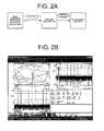
- FIGS. 2A-2Bare an illustration of a test configuration and a screen capture illustrating test results associated with an exemplary repeater DSSS configuration with phase modulation and WLAN only enabled.
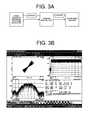
- FIGS. 3A-3Bare an illustration of a test configuration and a screen capture illustrating test results associated with an exemplary repeater DSSS configuration with phase modulation and WLAN only disenabled.
- FIGS. 4A-4Bare an illustration of a test configuration and a screen capture further illustrating the test results associated with an exemplary repeater DSSS configuration of FIG. 3 with phase modulation and WLAN only disenabled.
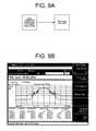
- FIGS. 5A-5Bare an illustration of a test configuration and a screen capture illustrating test results associated with an exemplary repeater orthogonal frequency division multiplexed (OFDM) configuration with no phase modulation and WLAN only enabled.
- OFDMorthogonal frequency division multiplexed
- FIGS. 6A-6Bare an illustration of a test configuration and a screen capture illustrating test results associated with an exemplary repeater OFDM configuration with phase modulation and WLAN only enabled.
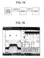
- FIGS. 7A-7Bare an illustration of a test configuration and a screen capture illustrating test results associated with an exemplary repeater OFDM configuration with phase modulation and WLAN only disenabled.
- FIGS. 8A-8Bare an illustration of a test configuration and a spectrum analyzer capture illustrating a signal generator output with no phase modulation.
- FIGS. 9A-9Bare an illustration of a test configuration and a spectrum analyzer capture illustrating a signal generator OFDM output with phase modulation.
- FIGS. 10A-10Bare an illustration of a test configuration and a spectrum analyzer capture illustrating a signal generator OFDM output with phase modulation and low loss surface acoustic wave (SAW) filter.
- SAWsurface acoustic wave
- FIGS. 11A-11Bare an illustration of a test configuration and a spectrum analyzer capture illustrating a signal generator OFDM output with phase modulation and low loss SAW filter and high reject SAW filter.
- FIGS. 12A-12Bare an illustration of a test configuration and a spectrum analyzer capture illustrating a signal generator DSSS output with no phase modulation.
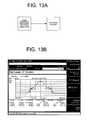
- FIGS. 13A-13Bare an illustration of a test configuration and a spectrum analyzer capture illustrating a signal generator DSSS output with phase modulation.
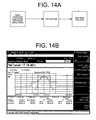
- FIGS. 14A-14Bare an illustration of a test configuration and a spectrum analyzer capture illustrating a signal generator DSSS output with phase modulation and a low loss SAW filter.
- FIGS. 15A-15Bare an illustration of a test configuration and a spectrum analyzer capture illustrating a signal generator DSSS output with phase modulation, a low loss SAW filter and a high reject SAW filter.
- FIG. 16is a block diagram illustrating an exemplary wireless network environment including two exemplary repeaters.
- FIG. 17is a connection diagram illustrating potential connections which may be established between exemplary repeaters, an AP and mobile communication station in a WLAN.
- FIG. 18Ais a schematic drawing illustrating an exemplary repeater in accordance with an exemplary embodiment.
- FIG. 18Bis a schematic drawing illustrating an exemplary repeater in accordance with another exemplary embodiment.
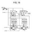
- FIG. 19is an exemplary circuit diagram of a timing circuit.
- FIG. 20is an exemplary circuit diagram of a bi-phase modulator.
- FIG. 21is a block diagram of an exemplary notch processor.
- FIG. 22is an illustration of exemplary notch insertion parameters.
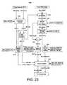
- FIG. 23is a flow diagram illustrating an exemplary notch detection signal processing.
- FIG. 24is a flow diagram illustrating an exemplary power adjustment routine for mitigating oscillation.
- the present disclosureconcerns a repeater configuration for mitigating oscillation.
- the instant disclosureis provided to further explain in an enabling fashion the best modes of performing one or more embodiments of the present invention.
- relational termssuch as first and second, and the like, if any, are used solely to distinguish one from another entity, item, or action without necessarily requiring or implying any actual such relationship or order between such entities, items or actions.
- some embodimentsmay include a plurality of processes or steps, which can be performed in any order, unless expressly and necessarily limited to a particular order; i.e., processes or steps that are not so limited may be performed in any order.
- a wide area connection 101which could be, for example, an Ethernet connection, a T1 line, a wideband wireless connection or any other electrical connection providing a data communications path, may be connected to a wireless gateway, or access point (AP) 100 .
- the wireless gateway 100sends RF signals, such as, for example, IEEE 802.11 packets or signals based upon Bluetooth, Hyperlan, or other wireless communication protocols, to client units 104 , 105 , which may be personal computers, personal digital assistants, or any other devices capable of communicating with other like devices through one of the above mentioned wireless protocols.
- a wireless gateway, AP, or client devicewill be referred to here as a wireless station.
- Respective propagation, or RF, paths to each of the client units 104 , 105are shown as 102 , 103 .
- the signals carried over RF path 102is of sufficient strength to maintain high-speed data packet communications between the client unit 104 and the wireless gateway 100 , the signals carried over the RF path 103 and intended for the client unit 105 would be attenuated when passing through a structural barrier such as walls 106 or 107 to a point where few, if any, data packets are received in either direction if not for wireless repeaters 200 , 204 .
- wireless repeaters 200 , 204receive packets transmitted on an initial frequency channel 201 from the wireless gateway 100 , access point or another repeater.
- the wireless repeater 200detects the presence of a packet on the first frequency channel 201 and receives the packet and re-transmits the packet with more power on a second frequency channel 202 .
- the wireless repeater 204detects the presence of the packet on the second frequency channel 202 , receives the packet and re-transmits the packet with more power on a third frequency channel 203 .
- the client unit 105operates on the third frequency channel, even though the wireless gateway 100 operates on the first frequency channel 203 .
- the wireless repeater 204detects the presence of a transmitted packet on the third frequency channel 203 from the client unit 105 , receives the packet on the third frequency channel 203 , and re-transmits the packet on the second frequency channel 202 .
- the wireless repeater 200detects the presence of a transmitted packet on the second frequency channel 202 from wireless repeater 204 , receives the packet on the second frequency channel 202 , and re-transmits the packet on the first frequency channel 201 .
- the wireless gateway 100then receives the packet on the first frequency channel 201 .
- the wireless repeaters 200 , 204are capable of simultaneously receiving and transmitting signals as well as extending the coverage and performance of the wireless gateway 100 to the client unit 105 .
- the repeaters 200 , 204can further act as a wireless bridge allowing two different groups of units to communicate where optimum RF propagation and coverage or, in many cases, any RF propagation and coverage was not previously possible.
- repeater systems using frequency translationmay encounter problems, for example, when beacon signals are used. Accordingly, range extension may be realized in such systems using repeaters for wireless local area networks and may be particularly advantageous when specific protocols are used, such as, for example, the 802.11 series of protocols by modifying the beacon signal to reflect the frequency translation.
- specific protocolssuch as, for example, the 802.11 series of protocols by modifying the beacon signal to reflect the frequency translation.
- problemsarise when adjacent nodes using or re-using translated frequencies within range of each other may establish false connections which lead to problems from node to node in terms of data traffic integrity. False connections may also lead to repeater to repeater oscillations when both repeaters are using the same frequency pairs and may further lead to system problems causing a general failure in the WLAN environment. The problems also arise on same frequency repeaters.
- Wireless repeaters 200 , 204convert packets from an initial frequency channel to a different frequency channel, where it may be received by one or more clients, such as station devices (STA) or client units 104 or 105 , or a different repeater.
- Client units 104 or 105preferably receive a beacon identifying an 802.11b channel as being the appropriate channel for communication, and would receive information packets translated by the repeater 200 , 204 from a first channel to a second channel.
- a problematic repeater conditionmay arise however, in exemplary scenario 300 , as illustrated FIG. 17 , wherein two repeaters R 1 320 and R 2 330 are configured to service one AP 310 which is within the transmit range of both repeaters via, for example, wireless connections 301 and 303 .
- Repeaters R 1 320 and R 2 330may further be capable of listening to each other's respective transmissions via a connection established over, for example, link 302 .
- the only connection established to communication unit or station device or STA 340is connection 304 which as will be appreciated is a wireless or RF link. Problems arise when repeaters R 1 320 and R 2 330 are operating on the same pair of channels, such as AP and repeater channels.
- both R 1 320 and R 2 330detect the transmission on, for example, a first frequency F 1 and retransmit on a second frequency F 2 , such as the repeater channel.
- F 1a first frequency
- F 2a second frequency
- R 2 330then repeats the transmission on F 1 to AP 310 .
- R 1 320detects the transmissions from R 2 330 on F 1 and tries to retransmit the detected transmissions. If R 1 320 happens to select F 2 as the transmit frequency, a loop will be established between R 1 320 and R 2 330 .
- the RF loopmay oscillate, via, for example, positive feedback causing any signals destined for STA 340 over connection 304 to be jammed. It should be noted that the above RF loop does not occur if both repeaters detect the signal on the F 1 because once they detect a signal on F 1 they disable their receivers on F 2 and then start repeating on F 2 .
- the repeater 1800may be, for example, a frequency translating repeater as discussed above or a same-frequency repeater.
- the repeater 1800includes first and second antennas (ANTA, ANT B) serving as reception and transmission devices for receiving and transmitting signals on first and second channels.
- a signal received via one of the first antenna ANTA or second antenna ANTBis processed by processing elements such as a low noise amplifier (LNA), image reject filter (IRF), field effect transistor (FET) mixer, surface acoustic wave (SAW) filters, amplifier, is split and propagated on two different signals paths by, for example, splitter 1816 .
- LNAlow noise amplifier
- IRFimage reject filter
- FETfield effect transistor
- SAWsurface acoustic wave
- One of the split signal paths from the splitter 1816is preferably coupled to a logarithmic amplifier 1820 via an amplifier and the other split signal path is preferably coupled to an adjustable gain control (AGC) element 1822 for adjusting the gain of the signal.
- a first output of the logarithmic amplifier 1820which is preferably a signal representative of the amplitude envelope of the received signal strength indication (RSSI), is fed to a control portion of the AGC element 1822 for adjusting the gain control, to a processor 1825 and to a comparator 1823 for comparing the RSSI level of the signal with a predetermined RSSI threshold received from the processor 1825 .
- RSSIreceived signal strength indication
- a second output of logarithmic amplifier 1820is fed to a digital demodulator 1824 via various digital elements for performing direct-sequence spread spectrum (DSSS) or orthogonal frequency-division multiplexing (OFDM) detection and demodulation, and internal packet generation.
- the digital demodulator 1824can perform such detection by, for example, analyzing preamble information specific to DSSS and OFDM WLAN packets generally located in the first few symbols of a packet, such as an 802.11 packet.
- the digital demodulator 1824 or the repeaterentirely can be placed in a WLAN only configuration by, for example, the processor 1825 .
- the output of the comparator 1823is fed to a sequencer 1826 (CMP_A_EN terminal).
- the comparator 1823can output a signal indicative of a detected signal when the RSSI is greater than the predetermined threshold, thus indicative of a signal to be repeated.
- the sequencer 1826will output an enable signal (not shown) to the demodulator 1824 to begin demodulating the signal as well as various control outputs that will begin the physical repeating of the signal. Subsequently, the sequencer 1826 will also output a signal to an AND gate 1828 .
- the AND gate 1828also receives a microprocessor enable signal from the processor 1825 , and outputs an enable signal to timing circuitry 1830 if the enable signals are received from both the sequencer 1826 and the processor 1825 .
- the timing circuitry 1830controls a bi-phase modulator (signal modification device) 1832 , which receives the output signal from the AGC element 1822 via an amplifier 1834 and additional circuitry.
- An exemplary circuit for the timing circuitry 1830is shown in FIG. 19 .
- PA_ENrepresents the enable signal from the sequencer 1826
- BPSK_ENrepresents the enable signal from the processor 1825 .
- 11 MHzis the clock for the timing circuitry 1830 .
- the bi-phase modulator 1832modifies the signal by adding an amount of phase variation to modulate, for example, the first few symbols of a packet to be repeated.
- the bi-phase modulator 1832can include, for example, transfer switches for switching the differential signal received from the amplifier 1834 to thereby add the phase variation.
- An exemplary circuit for the bi-phase modulator 1832is shown in FIG. 20 .
- the length of time for applying the phase modulation to the repeated signalcan be adjusted by the timing circuitry 1830 connected to the comparator output (see signals MOD_P and MOD_N which are from the timing circuitry 1830 ).
- the timing circuitry 1830can be triggered by a hit on the comparator 1823 . Once the timing circuitry 1830 stops, the switching of the positive and negative inputs can be stopped and normal operation can be commenced.
- the output of the bi-phase modulator 1832is fed to a SAW filter 1836 for removing any spectral splattering created by the phase modulation performed by the bi-phase modulator 1832 .
- the signalcan then be transmitted by one of the first or second antennas ANTA, ANTB via the mixer 1838 and additional analog elements to an access point, wireless station or client device (wireless station).
- the bi-phase modulator 1832can be coupled to, for example, a 1056 MHz linear oscillator 1840 and an active mixer 1842 .
- the length of time for applying the phase modulation to the repeated signalis still adjusted by the timing circuitry 1830 .
- the positive and negative inputs of the 1056 MHz linear oscillator 1840 going to the active mixer 1842can be switched back and forth at, for example, a 5.5 MHz rate. Switching the positive and negative inputs will impart the phase modulation onto the repeated signal.
- the timing circuitry 1830 stopsthe switching of the positive and negative inputs can be stopped and normal operation can be commenced.
- the digital demodulator 1824DSSS/OFDM detector
- the repeater 1800receives a repeated signal from a similar repeater 1800 , it will not re-repeat the signal. As a result, the problem related to oscillation as discussed above can be mitigated.
- phase variation added to the signal by the bi-phase modulator 1832is transparent to wireless stations receiving the modified signal because carrier recovery is not performed until, for example, the fifth or sixth symbol of an incoming stream.
- an external phase modulatorcan advantageously be placed after the amplifier 1834 .
- a simple timer to control the 5.5 MHz clockcan be generated by dividing down an existing clock such as an 11 MHz processor clock.
- the signal modificationcan be performed at the output of the mixer 1838 rather than the amplifier.
- the output of amplifier 1834is preferably used because of the difficulty accessing the data stream coming out of the modulator in order to add the phase at base-band for signals coming out of the modulator.
- the phase modulator 1832is triggered by either a comparator hit or anytime a modulated signal is generated.
- the signal modifiedmay be a self-generated signal or a received signal.
- the repeaters R 1 320 and R 2 330both include the digital demodulator 1824 and phase modulator 1832 , and are both placed in a WLAN only configuration
- the repeaters R 1 320 and R 2 330are operating on the same pair of channels, such as AP and repeater channels, when AP 310 transmits, both R 1 320 and R 2 330 detect the transmission on, for example, the first frequency F 1 and retransmit on the second frequency F 2 .
- the phase modulator 1832 of the repeatermodifies the first few symbols of packets in the transmitted signal.
- R 2 330When an isolated client station STA 340 transmits on F 2 , R 2 330 then repeats the transmission on F 1 to AP 310 .
- R 1 320detects the transmissions from R 2 330 on F 1 ; however, R 1 320 cannot demodulate the repeated signal because the first few symbols include the phase variation. Thus, the repeater R 2 330 does not retransmit the detected transmissions back onto F 2 302 . Even if R 1 320 happens to select F 2 as the transmit frequency, a loop will not be established between R 1 320 and R 2 330 .
- a further advantage of the repeater according to the various embodimentsis that limited or no additional analog, digital or I/O circuitry is needed for phase detection because such phase detection is performed by the existing circuitry for the OFDM/DSSS digital modulator.
- the circuitry for generating the phase modulationis extremely simple.
- the existing DSSS and OFDM detectorwill not recognize the packets associated with the phase modulated symbols as valid WLAN packets and will stop the repeating process.
- the biphase modulator 1832can be modified to perform the phase modulation of the preamble so that each packet has a unique signature.
- This signaturemay be a unique phase modulating “square wave” with a unique frequency of a set of frequencies or one of a set of orthogonal codes such as Walsh codes or the like. While it is not required that the code be orthogonal, orthogonal orientation between the codes is considered to allow for a higher performance of the detection of the one out of the set of codes with more certainty. Examples of non-orthogonal code would be ones with low cross correlations such as PN codes, Gold codes, or Barker sequences. Use of such codes as the modulation sequence by the repeater onto the preamble of the repeated packet will allow for (as previously mentioned) preventing the “wireless LAN only” detection of the signal to be prevented in a similar manner to the tests discussed below.
- the unique signaturecan be configured so that operation of a repeater receiving the modified signal is adjusted in accordance with the unique signature.
- the repeatercan be configured to take alternative actions such as transmitting the wireless signal at a frequency different from an original transmission frequency, or transmitting the wireless signal at a power level different from the original transmission power level in order to avoid oscillation.
- the repeatercould be configured to remove the unique signature from the signal.
- the repeatercan be configured to perform such actions in accordance with the processor 1825 executing instructions stored in an associated memory.
- the repeatercan use the phase modulation in the signal to perform a qualifying detection process to determine if the received wireless signal is from another repeater or one of the wireless stations.
- the phase modulationcan be correlated to predetermined signal pattern stored in the memory. If the correlation is determined to be high, then the repeater can determine that the wireless signal is from another repeater and take appropriate action to prevent oscillation.
- the qualifying detection processcan include demodulating one of a predetermined information sequence, a pilot channel and a pilot carrier.
- the search time for WLAN detection in an exemplary repeaterwas programmable from 4 ⁇ s to 16 ⁇ s.
- a digital signalwas generated using a Vector Signal Generator (VSG) having phase modulation on the first 4 ⁇ s for both an OFDM signal and a DSSS signal.
- VSGVector Signal Generator
- cessation of repeatingwas achieved 100% of the time for a programmed search time of 4 ⁇ s.
- the operating mode of the exemplary repeaterwas changed to “WLAN only” OFF.
- the signalsuccessfully transited the repeater 100% of the time and a Vector Signal Analyzer (VSA) successfully demodulated the repeated signal including the phase modulation.
- VSAVector Signal Analyzer
- the signalwas input with the phase modulation imposed directly from the VSG and, when output to the VSA, the signal with the direct modulation was again successfully demodulated.
- TIME DOMAIN OPERATIONReferring to FIGS. 1A-4B , test conditions and associated results for DSSS signals will be discussed.
- Test #1_DSSSa 1 Mbps DSSS signal was injected without any phase modulation into the exemplary repeater while WLAN Only was enabled and the output was measured.
- the exemplary repeaterfully repeated the signal and the VSA demodulator detected the Start Frame Delimiter (SFD) and Header.
- SFDStart Frame Delimiter
- Test #2_DSSSa 1 Mbps DSSS signal with Bi-Phase Modulation added to the first 4 ⁇ s of the signal was injected into the exemplary repeater while WLAN Only was enabled and the output was measured.
- the repeater in WLAN Only modeis set to search 4 ⁇ s for an 802.11g DSSS or OFDM packet.
- the exemplary repeaterrepeated only 4 ⁇ s (partial packet) and then stopped the transmission.
- Test #3_DSSSa 1 Mbps DSSS signal with Bi-Phase Modulation added to the first 4 ⁇ s of the signal was injected into the exemplary repeater while WLAN Only disabled and the output was measured.
- the exemplary repeatersince the WLAN Only mode is disabled, the exemplary repeater repeated the entire packet since it was not searching for DSSS or OFDM preambles, and the VSA detected and demodulated the packet.
- Test #3_DSSS Zooma zoomed version of Test #3_DSSS was performed in which the phase was added across the first 4 ⁇ s. As shown in FIG. 4B , the time domain signal appeared differently for the first 4 us compared to after 4 ⁇ s.
- Test #1_OFDMa 6 Mbps OFDM signal without any phase modulation was injected into the exemplary repeater with WLAN Only enabled and the output was measured. As shown in FIGS. 5A-5B , the exemplary repeater fully repeated the signal and the VSA demodulator detected and properly demodulated the signal.
- “Test #2_OFDM”a 6 Mbps OFDM signal with Bi-Phase Modulation added to the first 4 us of the signal was injected into the exemplary repeater with WLAN Only enabled and the output was measured.
- Exemplary repeater WLAN Onlywas set to search 4 ⁇ s for an 802.11g DSSS or OFDM. As shown in FIGS. 6A-6B , the exemplary repeater repeated only 4 ⁇ s (partial packet) and then stopped the transmission.
- Frequency Domain OperationReferring to FIGS. 8A-15B , spectral implications of adding the phase modulation to the signal for OFDM and DSSS and the appearance of the spectrum after being transmitted through the IF SAWs will be discussed. The test was performed at 594 MHz in order to determine if the signal could pass or be very close to the mask defined by the 802.11 standard.
- Test #1_OFDMa 6 Mbps OFDM signal was injected into the spectrum analyzer without any phase modulation. As shown in FIG. 8B , the signal generated passed the 802.11g spectral masks.
- Test #1_DSSSa 1 Mbps DSSS signal was injected into the spectrum analyzer without any phase modulation. As shown in FIG. 12B , the signal generated passed the 802.11b spectral masks.
- Test #2_DSSSa 1 Mbps DSSS signal was injected into the spectrum analyzer with phase modulation added to the first 4 ⁇ s of the waveform. As shown in FIG. 13B , the signal no longer passed or was close to failing the 802.11b spectral masks due to the phase modulation.
- a repeater including the bi-phase modulation device 1832can fully repeat a signal and not repeat a signal if a predetermined portion of the signal includes phase modulation and is in a WLAN only mode. Further, the modulated signal generated can pass through the 802.11 spectral masks when the modulated signal passes through one or more SAW filters.
- the bi-phase modulator 1832constitutes a signal modification device.
- a repeatercan include a notch processor 2100 configured to insert a notch pattern on a wireless signal to be repeated and detect if a notch pattern is present on a received wireless signal.
- the notch processor 2100can be included in the repeater 1800 shown in FIGS. 18A-18B as an additional signal modification device and detection device or in place of the bi-phase modulator 1832 .
- the notch patternis generally one or more notches starting at a specific time T START and separated by a gap duration T DURATION .
- the start time, gap duration, and notch durationare programmable for both insertion and detection.
- the detection notch patternis specified by setting the coefficients of the received notch matched filter.
- the notch processor 2100includes a notch insertion portion 2102 for sending a signal representative of the notch pattern (TX_NOTCH) to the sequencer 2104 , a notch detection portion 2106 for sending signals representative of an indication of a detected notch (RX_NOTCH_DET) and the particular channel on which the notch was detected (RX_NOTCH_CHAN) to the sequencer 2104 , a comparator portion 2108 that receives input signals (CMP_OUT_A, CMP_OUT_B) from the comparators via an internal RF interface 2110 , and clock and reset signals, and control registers 2112 for sending signal representative of a notch insertion start time TX_NOTCH_START, notch insertion gap control TX_NOTCH_GAP, and duration TX_NOTCH_DUR to the notch insertion portion 2102 .
- the comparator portion 2108receives signals representative of the RSSI voltages for the two channels and a clock signal from an RSSI analog to digital converter (ADC) interface 2113 , and outputs signals (RX_HYST_A, RX_HYST_B, and RX_ADC_SEL) to an optional debugging header portion 2114 for facilitating parameter adjustment.
- ADCanalog to digital converter
- the notch processor 2100further includes control and status registers 2116 for outputting various signals representative of: matched filter peak windows (RX_NOTCH_MFPW 1 , RX_NOTCH_MFPW 2 ); notch detection hysteresis control (RX_NOTCH_HYST); notch detection parameter control (RX_NOTCH_PAR 1 , RX_NOTCH_PAR 2 , RX_NOTCH_PAR 3 ); and notch detection matched filter coefficient control (RX_NOTCH_MFC 0 -MFC 19 ) to the notch detection section 2106 .
- the notch detection section 2106also outputs a signal representative of notch detection status (RX_NOTCH_STATUS) to the control and status registers 2116 .
- the notch processor 2100can insert one or two short notches in the signal to be repeated after the rising edge of CMP_OUT_A or CMP_OUT_B.
- the sequencer 2104applies the notch to the repeated signal whenever TX_NOTCH is 1. Exemplary notch processor operations for detecting a notch in a signal will be discussed with reference to the flow diagram shown in FIG. 23 .
- programmable hysteresisis performed to generate the hysteresis-filtered comparator outputs HYST_A, HYST_B, and the ADC channel selection signal ADC_SEL based upon the analog comparator outputs CMP_OUT_A, CMP_OUT_B.
- the signal RXND_HYST_CRis a signal from a control register indicative of the hysteresis span for CMP_OUT_A, CMP_OUT_B.
- RSSI channel selectionis performed based upon signals HYST_A, HYST_B, and a signal ADC_SEL representative of the selective channel is generated.
- HYST_A, HYST_B, and ADC_SELare used to control the signals from the timer MFPW_TMR for controlling the detection window timing. The timer control is performed based upon the number of clock cycles elapsed since the packet's start. MFPW_TMR continues counting during temporary signal dropouts shorter than RXND_DROPOUT_CR clock cycles. Such dropouts frequently occur during the notch pattern at low received signal strengths.
- ADC_SELis used to convert the two-channel interleaved RSSI output ADC_OUT into a single-channel de-multiplexed signal ADC_DATA.
- ADC_DATAis processed through a non-linear “maximum of 3” operation to generate ADC_MAX.
- RXND_MAX_DISABLE_CRis for disabling the use of the 3-sample maximum.
- ADC_MAXis processed through a linear first-order programmable lowpass filter, which yields a slowly-varying value RSSI_AVG that closely tracks the received signal envelope peak excursions.
- RSSI_VALis subtracted from RSSI_AVG to yield the (signed) difference signal DIFF, which exhibits a strong positive excursion when a notch is encountered.
- DIFFis the input to a 20-tap programmable matched filter, whose unsigned output MF_SUM is clipped to the range 0 to 255.
- Signal RXND_MFC[0-19]_ENAis representative of a match filter tap status
- RXND_MFC[0-19]_SIGNis representative of a matched filter tap coefficient sign
- signal RXND_MFC[0-19]_SHIFTis representative of a matched filter tap coefficient magnitude.
- RSSI_AVGis used to compute a variable matched filter threshold MF_THRESH based on the values of parameter control registers RXND_MFT_CONST_CR, RXND_MFT_SLOPE_CR, and RXND_MFT_MAX_CR.
- the notch detection sectionsets RX_NOTCH_DET to 1 and sets RX_NOTCH_CHAN equal to ADC_SEL, whenever MF_SUM equals or exceeds MF_THRESH during a narrow time window specified by control registers RXND_NOM_MFPW_CR and RXND_HWIN_MFPW_CR.
- the signals RX_NOTCH_DET and RX_NOTCH_CHANare sent to the sequencer 2104 .
- a repeater including the notch processor 2100 according to the second embodimentcan add a notch pattern to a repeated signal and detect a notch pattern in a received signal to mitigate the oscillation problem discussed above.
- the notch processor 2100constitutes a signal modification device.
- a repeatersuch as the repeater 1800 shown in FIGS. 18A-18B executes a power adjustment routine to stop or prevent oscillation with one or more other repeaters.
- the routinecan begin when the repeater 1800 enters a discovery mode upon determining that another repeater within the wireless network is operating in the same frequency channel as disclosed in, for example, U.S. Patent Publication No. 2006-0041680.
- the repeater 1800can be configured to execute the routine by the processor 1825 executing instructions stored in the memory 1827 .
- the repeatertransmits a predetermined number of XOS_PROBE_REQUEST packets, and at 2410 measures the XOS_PROBE_RESPONSE RSSI.
- the packetscan be generated by, for example, the digital demodulator 1824 under the control of the processor 1825 .
- the XOS_PROBE_REQUEST packetcontains the power at which the repeater is transmitting. The difference between the transmit power and measured RSSI is the one-way path loss.
- the repeaterdetermines if this path loss is less than a predetermined value such as, for example, 80 dB. If the path loss is less than 80 dB (YES at 2415 ), then at 2420 the repeater will mark this channel and all channels within a 5 channel separation as unavailable for use, and the routine ends.
- the repeatertransmits a number of XOS packets of a maximum length (64 bytes).
- the RSSI from each successfully received packetis measured and averaged across all packets. A packet which has not been successfully received will be considered to have an RSSI of ⁇ 80 dBm.
- the repeaterdetermines if the average RSSI is less than a predetermined dBm. If the average RSSI is less than the predetermined dBm (YES at 2435 ), then the routine ends. That is, the discovering repeater will assume that the current transmit power is acceptable and begin normal operation.
- the repeaterdetermines if the average RSSI is less than the predetermined dBm. If the average RSSI is less than the predetermined dBm (YES at 2450 ), then the repeater begins normal operation.
- the repeaterIf the average RSSI is not less than the predetermined dBm (NO at 2450 ), then at 2455 the repeater requests that the other repeater(s) on the same channel reduce the transmit power by 1 dB. At 2460 the repeater transmits the number of XOS packets. At 2465 , the RSSI from each successfully received packet is measured and averaged across all packets. At 2470 , the repeater determines if the average RSSI is less than the predetermined dBm. If the average RSSI is less than the predetermined dBm (YES at 2470 ), then the repeater begins normal operation.
- the repeateronce again request that the other repeater(s) on its same channel reduce the transmit power by another 1 dB. This will continue with each repeater's power being dropped by 1 dBm, in turn, until the XOS packet test passes.
- the non-discovering repeaterwould have to reduce it's transmit power to less than a predetermined amount such as, for example, 9 dB, the discovering repeater will request that the other repeater return to its original transmit power and the discovering repeater can choose a different channel to repeat onto. The current channel and all channels within a 5 channel separation will be marked as unavailable.
- the repeaterWhile the repeater is operating on the same channels as another repeater, the repeater which was enabled last will enable a monitor that checks for oscillations to occur. When an oscillation is detected, the repeater will perform the same power routine discussed above ( 2405 - 2420 ).
- the monitoring repeaterwill attempt to increase it's transmit power by 1 dB until it has reached it's normal maximum transmit power.
- an XOS test2405 - 2420 ) will be performed to see if the increase is warranted. It will ratchet each side up in the same manner as the powers were dropped.
- a repeaterOnce a repeater has been requested to change the transmit power by another repeater, it can monitor the channel for a XOS_OSCMIT_HEARTBEAT messages from the controlling repeater. If a predetermined time period such as, for example, 20 seconds passes without receiving a heartbeat message from the controlling repeater, the slave unit will assume that the controlling repeater is no longer operating and will revert the power to the normal maximum transmit power for channel spacing configuration.
- the above routinecan also be applied when more than one other repeater is repeating to the same channels. However, in such as case a monitoring repeater may choose not to increase the power if it has determined within the certain time period (e.g., 10 seconds) that an oscillation would occur by doing so.
- a certain time periode.g. 10 seconds
- the repeater 1800can execute the power adjustment routine to mitigate oscillation with one or more other receivers on a same channel within a wireless network.
- the repeatermay be modified to identify packets previously repeated, and perform an action in response.
- the actionmay be to terminate transmission for oscillation mitigation, or to allow repeating depending on the specifics of the detection.
- a repeatercan incorporate any number of the three embodiments discussed above. That is, the repeater is not limited to only one of the above-discussed embodiments.
- the circuits discussed aboveare only exemplary manner for implementing the above described signal modification device. That is, the bi-phase modulation device 1832 and the notch processor 2100 can be implemented in a different manner, as long as a predetermined portion of the signal is modified so that a repeater receiving the modified signal takes an action different from its normal repeating action.
Landscapes
- Engineering & Computer Science (AREA)
- Computer Networks & Wireless Communication (AREA)
- Signal Processing (AREA)
- Mobile Radio Communication Systems (AREA)
- Radio Relay Systems (AREA)
Abstract
Description
Claims (7)
Priority Applications (1)
| Application Number | Priority Date | Filing Date | Title |
|---|---|---|---|
| US12/307,904US8559379B2 (en) | 2006-09-21 | 2007-09-21 | Method and apparatus for mitigating oscillation between repeaters |
Applications Claiming Priority (3)
| Application Number | Priority Date | Filing Date | Title |
|---|---|---|---|
| US84607306P | 2006-09-21 | 2006-09-21 | |
| US12/307,904US8559379B2 (en) | 2006-09-21 | 2007-09-21 | Method and apparatus for mitigating oscillation between repeaters |
| PCT/US2007/020485WO2008036401A2 (en) | 2006-09-21 | 2007-09-21 | Method and apparatus for mitigating oscillation between repeaters |
Publications (2)
| Publication Number | Publication Date |
|---|---|
| US20090290526A1 US20090290526A1 (en) | 2009-11-26 |
| US8559379B2true US8559379B2 (en) | 2013-10-15 |
Family
ID=39201114
Family Applications (1)
| Application Number | Title | Priority Date | Filing Date |
|---|---|---|---|
| US12/307,904Expired - Fee RelatedUS8559379B2 (en) | 2006-09-21 | 2007-09-21 | Method and apparatus for mitigating oscillation between repeaters |
Country Status (9)
| Country | Link |
|---|---|
| US (1) | US8559379B2 (en) |
| EP (1) | EP2064903A4 (en) |
| JP (1) | JP5199261B2 (en) |
| KR (1) | KR101123600B1 (en) |
| CN (1) | CN101595657B (en) |
| BR (1) | BRPI0717490A2 (en) |
| CA (1) | CA2663419C (en) |
| RU (1) | RU2444159C2 (en) |
| WO (1) | WO2008036401A2 (en) |
Cited By (8)
| Publication number | Priority date | Publication date | Assignee | Title |
|---|---|---|---|---|
| US20090323582A1 (en)* | 2006-10-26 | 2009-12-31 | Qualcomm Incorporated | Repeater techniques for multiple input multiple output utilizing beam formers |
| US20120100883A1 (en)* | 2009-04-29 | 2012-04-26 | Electronics And Telecommunications Research Institute | Transmission power control method and device for cognitive radio device |
| US20140064116A1 (en)* | 2012-08-31 | 2014-03-06 | Apple Inc. | Proximity and tap detection using a wireless system |
| US20140065995A1 (en)* | 2011-05-05 | 2014-03-06 | Ste S.A.S. Di G. Moiraghi & C. | Receiver of radio frequency signals |
| US8885688B2 (en) | 2002-10-01 | 2014-11-11 | Qualcomm Incorporated | Control message management in physical layer repeater |
| US9553656B2 (en) | 2011-06-08 | 2017-01-24 | Andrew Wireless Systems Gmbh | System and method for reducing desensitization of a base station transceiver for mobile wireless repeater systems |
| US9936396B2 (en) | 2013-04-29 | 2018-04-03 | Cellphone-Mate, Inc. | Apparatus and methods for radio frequency signal boosters |
| US20200389142A1 (en)* | 2019-06-05 | 2020-12-10 | Wilson Electronics, Llc | Power amplifier (pa)-filter output power tuning |
Families Citing this family (16)
| Publication number | Priority date | Publication date | Assignee | Title |
|---|---|---|---|---|
| ATE403286T1 (en)* | 2002-06-21 | 2008-08-15 | Qualcomm Inc | INTERMEDIATE AMPLIFIER FOR WIRELESS LOCAL NETWORKS |
| US8942159B2 (en) | 2010-07-05 | 2015-01-27 | Hytera Communications Corp., Ltd. | Terminal in digital mobile radio relay system, transmission power regulation method and system thereof |
| CN101902807B (en)* | 2010-07-05 | 2013-02-06 | 海能达通信股份有限公司 | Terminal of digital mobile wireless transferring system, method for adjusting transmission power thereof and system thereof |
| CN102143508A (en)* | 2010-12-06 | 2011-08-03 | 华为终端有限公司 | Upgrading method and upgrading device for wireless repeater |
| US8626060B2 (en)* | 2011-04-14 | 2014-01-07 | Qualcomm, Incorporated | Beacon signals for repeaters within a wireless communications system |
| US8649418B1 (en) | 2013-02-08 | 2014-02-11 | CBF Networks, Inc. | Enhancement of the channel propagation matrix order and rank for a wireless channel |
| US8422540B1 (en) | 2012-06-21 | 2013-04-16 | CBF Networks, Inc. | Intelligent backhaul radio with zero division duplexing |
| US9295022B2 (en)* | 2012-05-18 | 2016-03-22 | Comcast Cable Communications, LLC. | Wireless network supporting extended coverage of service |
| US20140105251A1 (en)* | 2012-10-16 | 2014-04-17 | Effigis Geo Solutions | Leakage detection in an all-digital cable distribution network |
| CN104135316B (en)* | 2013-05-03 | 2017-11-21 | 中国移动通信集团公司 | A kind of via node |
| US10334085B2 (en)* | 2015-01-29 | 2019-06-25 | Splunk Inc. | Facilitating custom content extraction from network packets |
| US20170244497A1 (en)* | 2015-10-16 | 2017-08-24 | Solid RF Communication, Co., Ltd. | Detection of oscillations in signal amplifiers |
| CN109328440A (en)* | 2016-04-05 | 2019-02-12 | 威尔逊电子有限责任公司 | Narrow band signal for network protection detects |
| EP3577797B1 (en)* | 2017-01-31 | 2023-08-16 | Wilson Electronics, LLC | Reducing oscillation in a signal booster |
| US20180238574A1 (en)* | 2017-02-17 | 2018-08-23 | Johnson Controls Technology Company | Hvac system with wireless waveguide system |
| EP3509229B1 (en)* | 2018-01-04 | 2022-03-02 | Wilson Electronics, LLC | Detection of line loss in signal booster system |
Citations (310)
| Publication number | Priority date | Publication date | Assignee | Title |
|---|---|---|---|---|
| US3363250A (en) | 1965-07-20 | 1968-01-09 | Jacobson Irving | Monitoring system for remote radio control |
| US4000467A (en) | 1975-10-24 | 1976-12-28 | Bell Telephone Laboratories, Incorporated | Automatic repeater stressing |
| US4001691A (en) | 1975-01-30 | 1977-01-04 | Gruenberg Elliot | Communications relay system |
| US4061970A (en) | 1976-05-19 | 1977-12-06 | E.L.A.P. | Transmission system and repeater stations therefor |
| US4081752A (en) | 1975-05-30 | 1978-03-28 | Sanyo Electric Co., Ltd. | Digital frequency synthesizer receiver |
| US4124825A (en) | 1976-09-21 | 1978-11-07 | The Post Office | Signal level stabilizer |
| US4204016A (en) | 1975-07-25 | 1980-05-20 | Chavannes Marc A | Reinforced paper products |
| US4334323A (en) | 1980-09-08 | 1982-06-08 | Zenith Radio Corporation | Self tracking tuner |
| US4368541A (en) | 1980-06-30 | 1983-01-11 | Evans Robert M | Multiplexing arrangement for a plurality of voltage controlled filters |
| US4509206A (en) | 1982-05-04 | 1985-04-02 | Thomson-Csf | Receiver for multicarrier signals protected from unwanted signals |
| US4679243A (en)* | 1984-08-17 | 1987-07-07 | National Research Development Corporation | Data transmission using a transparent tone-in band system |
| US4701935A (en) | 1985-01-09 | 1987-10-20 | Nec Corporation | One frequency repeater for a digital microwave radio system with cancellation of transmitter-to-receiver interference |
| US4723302A (en) | 1986-08-05 | 1988-02-02 | A. C. Nielsen Company | Method and apparatus for determining channel reception of a receiver |
| US4777653A (en) | 1985-12-20 | 1988-10-11 | Telecommunications Radioelectriques Et Telephoniques T.R.T. | Apparatus for controlling transmission power over a digital radio communication channel |
| US4783843A (en) | 1986-05-23 | 1988-11-08 | Peninsula Engineering Group, Inc. | Split band filter for cellular mobile radio |
| US4820568A (en) | 1987-08-03 | 1989-04-11 | Allied-Signal Inc. | Composite and article using short length fibers |
| US4922259A (en) | 1988-02-04 | 1990-05-01 | Mcdonnell Douglas Corporation | Microstrip patch antenna with omni-directional radiation pattern |
| US5023930A (en)* | 1987-08-03 | 1991-06-11 | Orion Industries, Inc. | Booster with detectable boost operation |
| US5095528A (en) | 1988-10-28 | 1992-03-10 | Orion Industries, Inc. | Repeater with feedback oscillation control |
| CA2051283A1 (en) | 1990-09-21 | 1992-03-22 | Paul Wilkinson Dent | Diversity receiving system |
| EP0523687A2 (en) | 1991-07-18 | 1993-01-20 | Fujitsu Limited | Mobile telecommunication system having an expanded operational zone |
| US5214788A (en) | 1989-05-10 | 1993-05-25 | Thomson - Csf | Process and device for information transmission between radioelectric transceivers of the same network operating in frequency hopping |
| US5220562A (en) | 1989-05-12 | 1993-06-15 | Hitachi, Ltd. | Bridge apparatus and a communication system between networks using the bridge apparatus |
| US5280480A (en) | 1991-02-21 | 1994-01-18 | International Business Machines Corporation | Source routing transparent bridge |
| GB2272599A (en) | 1992-11-12 | 1994-05-18 | Nokia Telecommunications Oy | A method of cellular radio communication and a cellular radio system for use in such method |
| US5333175A (en) | 1993-01-28 | 1994-07-26 | Bell Communications Research, Inc. | Method and apparatus for dynamic power control in TDMA portable radio systems |
| US5341364A (en) | 1992-06-02 | 1994-08-23 | At&T Bell Laboratories | Distributed switching in bidirectional multiplex section-switched ringtransmission systems |
| US5349463A (en) | 1990-08-17 | 1994-09-20 | Victor Company Of Japan | Optical radio repeater with signal quality detection |
| US5368897A (en) | 1987-04-03 | 1994-11-29 | Fujitsu Limited | Method for arc discharge plasma vapor deposition of diamond |
| US5371734A (en) | 1993-01-29 | 1994-12-06 | Digital Ocean, Inc. | Medium access control protocol for wireless network |
| US5373503A (en) | 1993-04-30 | 1994-12-13 | Information Technology, Inc. | Group randomly addressed polling method |
| US5383144A (en) | 1990-11-20 | 1995-01-17 | Matsushita Electric Industrial Co., Ltd. | Subsampling method and interpolation method of digital signals |
| WO1995005037A1 (en) | 1993-08-06 | 1995-02-16 | Ntt Mobile Communications Network Inc. | Receiver and repeater for spread spectrum communication |
| US5408618A (en) | 1992-07-31 | 1995-04-18 | International Business Machines Corporation | Automatic configuration mechanism |
| US5408197A (en) | 1993-03-04 | 1995-04-18 | Mitsubishi Denki Kabushiki Kaisha | Automatic power control circuit for controlling transmitting power of modulated radio frequency signal |
| US5430726A (en) | 1991-01-18 | 1995-07-04 | Moorwood; Charles A. | Repeater interface controller with a shared data bus |
| US5446770A (en) | 1993-03-31 | 1995-08-29 | Matsushita Electric Industrial Co., Ltd. | Time division duplex transceiver |
| US5465251A (en) | 1992-06-23 | 1995-11-07 | International Business Machines Corporation | Network addressing |
| US5471642A (en) | 1994-01-28 | 1995-11-28 | Palmer; James K. | Re-broadcast system for a plurality of AM signals |
| US5485486A (en) | 1989-11-07 | 1996-01-16 | Qualcomm Incorporated | Method and apparatus for controlling transmission power in a CDMA cellular mobile telephone system |
| US5509028A (en) | 1993-03-26 | 1996-04-16 | Matra Communication | Radio transmission method using repeater stations with spectrum reversal |
| EP0709973A1 (en) | 1994-10-24 | 1996-05-01 | Ntt Mobile Communications Network Inc. | Transmission power control scheme for mobile communication system |
| US5515376A (en) | 1993-07-19 | 1996-05-07 | Alantec, Inc. | Communication apparatus and methods |
| US5519619A (en) | 1994-03-14 | 1996-05-21 | Motorola, Inc. | Route planning method for hierarchical map routing and apparatus therefor |
| WO1996022636A1 (en) | 1995-01-17 | 1996-07-25 | Robert Joseph Gerard Macnamee | Radio communications systems with repeaters using identification codes |
| US5608755A (en) | 1994-10-14 | 1997-03-04 | Rakib; Selim | Method and apparatus for implementing carrierless amplitude/phase encoding in a network |
| US5610916A (en) | 1995-03-16 | 1997-03-11 | Bell Atlantic Network Services, Inc. | Shared receiving systems utilizing telephone cables as video drops |
| US5648984A (en) | 1994-08-10 | 1997-07-15 | Alcatel Networks Systems, Inc. | Multidirectional repeater for data transmission between electrically isolated and/or physically different signal transmission media |
| US5654979A (en) | 1995-01-13 | 1997-08-05 | Qualcomm Incorporated | Cell site demodulation architecture for a spread spectrum multiple access communication systems |
| US5659879A (en) | 1993-07-30 | 1997-08-19 | Alcatel N.V. | Method of covering shadow areas in a cellular mobile radio system and radio booster for implementing this method |
| US5678177A (en) | 1992-07-14 | 1997-10-14 | 2777321 Canada Ltd. | RF repeaters for time division duplex cordless telephone system |
| US5678198A (en) | 1991-05-22 | 1997-10-14 | Southwestern Bell Technology Resources, Inc. | System for controlling signal level at both ends of a transmission link, based upon a detected value |
| US5684801A (en) | 1994-12-30 | 1997-11-04 | Lucent Technologies | Portable wireless local area network |
| US5697052A (en) | 1995-07-05 | 1997-12-09 | Treatch; James E. | Cellular specialized mobile radio system |
| US5726980A (en) | 1995-03-30 | 1998-03-10 | Northern Telecom Limited | Time division duplex communications repeater |
| US5732334A (en) | 1996-07-04 | 1998-03-24 | Mitsubishi Denki Kabushiki Kaisha | Radio transmitter and method of controlling transmission by radio transmitter |
| US5745846A (en) | 1995-08-07 | 1998-04-28 | Lucent Technologies, Inc. | Channelized apparatus for equalizing carrier powers of multicarrier signal |
| US5754540A (en) | 1995-07-18 | 1998-05-19 | Macronix International Co., Ltd. | Expandable integrated circuit multiport repeater controller with multiple media independent interfaces and mixed media connections |
| US5764636A (en) | 1996-03-28 | 1998-06-09 | Cisco Technology, Inc. | Color blocking logic mechanism for a high-performance network switch |
| EP0847146A2 (en) | 1996-12-05 | 1998-06-10 | Nec Corporation | A transmission power control apparatus for a mobile communication system |
| US5767788A (en) | 1996-03-19 | 1998-06-16 | Ness; James C. | Computer aided dispatch and locator cellular system |
| US5771174A (en) | 1995-12-21 | 1998-06-23 | Measurex Corporation | Distributed intelligence actuator controller with peer-to-peer actuator communication |
| EP0853393A1 (en) | 1996-06-27 | 1998-07-15 | Ntt Mobile Communications Network Inc. | Transmitted power controller |
| US5784683A (en) | 1995-05-16 | 1998-07-21 | Bell Atlantic Network Services, Inc. | Shared use video processing systems for distributing program signals from multiplexed digitized information signals |
| US5794145A (en) | 1996-06-07 | 1998-08-11 | Telxon Corporation | Mobile device multiband antenna system |
| EP0860953A1 (en) | 1997-02-21 | 1998-08-26 | Sagem Sa | Method of radiotelephone communication between a base station and a mobile telephone by means of a repeater |
| US5812933A (en) | 1992-12-30 | 1998-09-22 | Radio Communication Systems Ltd. | Duplex RF repeater for personal communications system |
| US5815795A (en) | 1995-08-25 | 1998-09-29 | Sumitomo Electric Industries, Ltd. | Oscillation detecting system for wireless repeater |
| US5825809A (en) | 1996-01-20 | 1998-10-20 | Samsung Electronics Co., Ltd. | Digital filter having an energy level detector for selecting a coefficient |
| RU2120702C1 (en) | 1991-02-01 | 1998-10-20 | Бритиш Телекоммьюникейшнз Паблик Лимитед Компани | Method for decoding of single received current signal from sequence of two-channel encoded video signals and device which implements said method |
| KR19980063664U (en) | 1997-04-18 | 1998-11-25 | 임경춘 | Lubricant supply structure of shift fork for manual transmission |
| US5852629A (en) | 1993-12-10 | 1998-12-22 | Fujitsu Limited | Repeater |
| US5857144A (en) | 1996-08-09 | 1999-01-05 | Ericsson, Inc. | In-band vehicular repeater for trunked radio system |
| US5862207A (en) | 1995-03-06 | 1999-01-19 | Toshiba Corporation | Method and system for providing virtual telephone terminals |
| US5875179A (en) | 1996-10-29 | 1999-02-23 | Proxim, Inc. | Method and apparatus for synchronized communication over wireless backbone architecture |
| US5883884A (en) | 1996-04-22 | 1999-03-16 | Roger F. Atkinson | Wireless digital communication system having hierarchical wireless repeaters with autonomous hand-off |
| US5884181A (en) | 1996-01-19 | 1999-03-16 | Bell Communications Research, Inc. | Interference reduction in shared-frequency wireless communication systems |
| US5890055A (en) | 1995-07-28 | 1999-03-30 | Lucent Technologies Inc. | Method and system for connecting cells and microcells in a wireless communications network |
| US5903553A (en) | 1995-12-08 | 1999-05-11 | Victor Company Of Japan, Ltd. | Enhanced signal collision detection method in wireless communication system |
| US5907794A (en) | 1994-03-03 | 1999-05-25 | Nokia Telecommunications Oy | Controlling a subscriber station on a direct mode channel |
| US5963846A (en) | 1997-03-31 | 1999-10-05 | Motorola, Inc. | Method and system for repeating pages |
| US5963847A (en) | 1995-10-26 | 1999-10-05 | Ntt Mobile Communications Network Inc. | Booster system |
| US5987304A (en) | 1996-05-31 | 1999-11-16 | Allgon Ab | Repeater with variable bandwidth |
| US6005884A (en) | 1995-11-06 | 1999-12-21 | Ems Technologies, Inc. | Distributed architecture for a wireless data communications system |
| US6005855A (en) | 1995-04-28 | 1999-12-21 | Qualcomm Incorporated | Method and apparatus for providing variable rate data in a communications system using statistical multiplexing |
| US6014380A (en) | 1997-06-30 | 2000-01-11 | Sun Microsystems, Inc. | Mechanism for packet field replacement in a multi-layer distributed network element |
| JP2000031877A (en) | 1998-07-09 | 2000-01-28 | Sharp Corp | Mobile communication system |
| US6032194A (en) | 1997-12-24 | 2000-02-29 | Cisco Technology, Inc. | Method and apparatus for rapidly reconfiguring computer networks |
| JP2000082983A (en) | 1998-09-03 | 2000-03-21 | Kokusai Electric Co Ltd | Wireless relay amplifier |
| US6061548A (en) | 1997-07-17 | 2000-05-09 | Metawave Communications Corporation | TDMA repeater eliminating feedback |
| CN1256032A (en) | 1998-01-30 | 2000-06-07 | 松下电器产业株式会社 | Method of directional reception using array antenna, and adaptive array antenna unit |
| US6088570A (en) | 1998-11-24 | 2000-07-11 | Airnet Communications Corporation | Method and apparatus employing delay elements in multiple diversity paths of a wireless system repeater translator to allow for selective diversity and automatic level control in a time-division multiple access system |
| JP2000509536A (en) | 1996-05-13 | 2000-07-25 | マイクロン・コミュニケーションズ・インコーポレイテッド | High frequency data communication equipment |
| US6101400A (en) | 1997-08-20 | 2000-08-08 | Interwave Communications, Inc. | Methods and apparatus for improved base station transceivers |
| US6108364A (en) | 1995-08-31 | 2000-08-22 | Qualcomm Incorporated | Time division duplex repeater for use in a CDMA system |
| JP2000236290A (en) | 1999-02-15 | 2000-08-29 | Nec Eng Ltd | Satellite communications system |
| WO2000050971A2 (en) | 1999-02-25 | 2000-08-31 | Berkeley Concept Research Corporation | Multichannel distributed wireless repeater network |
| JP2000269873A (en) | 1999-03-12 | 2000-09-29 | Kokusai Electric Co Ltd | Wireless relay amplifier |
| US6128512A (en) | 1995-09-06 | 2000-10-03 | Cisco Systems, Inc. | Cellular communication system with dedicated repeater channels |
| US6128729A (en) | 1997-12-16 | 2000-10-03 | Hewlett-Packard Company | Method and system for automatic configuration of network links to attached devices |
| US6141335A (en) | 1996-12-06 | 2000-10-31 | Hitachi, Ltd. | Radio communication system |
| US6163276A (en) | 1999-05-17 | 2000-12-19 | Cellnet Data Systems, Inc. | System for remote data collection |
| GB2351420A (en) | 1999-06-23 | 2000-12-27 | Motorola Ltd | Power control in a radio communication system |
| JP2001016152A (en) | 1999-06-30 | 2001-01-19 | Mitsubishi Electric Corp | Wireless relay device |
| US6188719B1 (en) | 1996-09-17 | 2001-02-13 | Alcatel Espace | Radiocommunication system repeater |
| US6188694B1 (en) | 1997-12-23 | 2001-02-13 | Cisco Technology, Inc. | Shared spanning tree protocol |
| US6195051B1 (en) | 1999-04-08 | 2001-02-27 | Motorola, Inc. | Microstrip antenna and method of forming same |
| US6202114B1 (en) | 1997-12-31 | 2001-03-13 | Cisco Technology, Inc. | Spanning tree with fast link-failure convergence |
| US6215982B1 (en) | 1996-06-28 | 2001-04-10 | Cisco Systems, Inc. | Wireless communication method and device with auxiliary receiver for selecting different channels |
| JP2001111575A (en) | 1999-08-03 | 2001-04-20 | Matsushita Electric Ind Co Ltd | Wireless LAN cross channel conversion repeater device and wireless terminal device |
| US6222503B1 (en) | 1997-01-10 | 2001-04-24 | William Gietema | System and method of integrating and concealing antennas, antenna subsystems and communications subsystems |
| JP2001136115A (en) | 1999-11-01 | 2001-05-18 | Mitsubishi Electric Corp | Method for removing looping waves in antenna device for relay station |
| US6272351B1 (en) | 1996-12-19 | 2001-08-07 | Cisco Technology, Inc. | System and method for relaying signals to base stations in a wireless communications system |
| JP2001217896A (en) | 2000-01-31 | 2001-08-10 | Matsushita Electric Works Ltd | Wireless data communication system |
| US6285863B1 (en) | 1999-11-24 | 2001-09-04 | Lucent Technologies Inc. | System and method for providing automatic gain control with high dynamic range |
| JP2001244864A (en) | 2000-02-29 | 2001-09-07 | Hitachi Ltd | Wireless relay system |
| US6298061B1 (en) | 1997-07-30 | 2001-10-02 | Cisco Technology, Inc. | Port aggregation protocol |
| US20010028638A1 (en) | 1998-10-02 | 2001-10-11 | Walton Jay R. | Methods and apparatuses for fast power control of signals transmitted on a multiple access channel |
| WO2001076098A2 (en) | 2000-03-30 | 2001-10-11 | Qualcomm Incorporated | Method and apparatus for controlling transmissions of a communications system |
| US6304563B1 (en) | 1999-04-23 | 2001-10-16 | Qualcomm Incorporated | Method and apparatus for processing a punctured pilot channel |
| US6304575B1 (en) | 1998-08-31 | 2001-10-16 | Cisco Technology, Inc. | Token ring spanning tree protocol |
| US20010040699A1 (en) | 1996-04-10 | 2001-11-15 | Hidefumi Osawa | Image processing apparatus and method |
| US20010050906A1 (en) | 1996-05-28 | 2001-12-13 | Joseph P. Odenwalder | High data rate cdma wireless communication system |
| US20010050580A1 (en) | 1996-05-13 | 2001-12-13 | O'toole James E. | Radio frequency data communications device |
| US6331792B1 (en) | 2000-06-30 | 2001-12-18 | Conexant Systems, Inc. | Circuit and method for unlimited range frequency acquisition |
| US20010054060A1 (en) | 2000-06-16 | 2001-12-20 | Fillebrown Lisa A. | Personal wireless network |
| JP2001357480A (en) | 2000-06-12 | 2001-12-26 | Matsushita Electric Ind Co Ltd | Emergency call device |
| US20020004924A1 (en) | 2000-05-24 | 2002-01-10 | Samsung Electronics Co., Ltd. | Data transmission apparatus and method for an HARQ data communication system |
| US6339694B1 (en) | 1998-03-30 | 2002-01-15 | Airnet Communications Corporation | Method and apparatus employing automatic RF muting and wireless remote control of RF downlink transmission for a wireless repeater |
| US6342777B1 (en) | 1997-03-04 | 2002-01-29 | Kokusai Electric Co., Ltd. | Time divisional duplex (TDD) system portable telephone relay device |
| WO2002008857A2 (en) | 2000-07-20 | 2002-01-31 | Cadence Design Systems, Inc. | A bridging apparatus for interconnecting a wireless pan and a wireless lan |
| JP2002033691A (en) | 2000-06-05 | 2002-01-31 | Sony Internatl Europ Gmbh | Active reflector and wireless data communication system |
| US20020018479A1 (en)* | 2000-07-26 | 2002-02-14 | Hajime Kikkawa | Data relay unit and multiplex communication system capable of inhibiting data relay in response to failure |
| US20020018487A1 (en) | 2000-04-06 | 2002-02-14 | Song Chen | Virtual machine interface for hardware reconfigurable and software programmable processors |
| WO2002017572A2 (en) | 2000-08-18 | 2002-02-28 | Nortel Networks Limited | Seamless roaming options in an ieee 802.11 compliant network |
| US6363068B1 (en) | 1997-06-18 | 2002-03-26 | Nec Corporation | Bridge and method of improving transmission efficiency of the same |
| US6370369B1 (en) | 1999-06-23 | 2002-04-09 | Sony International (Europe) Gmbh | Network device and method employing omni-directional and directional antennas |
| US6370185B1 (en) | 1999-08-10 | 2002-04-09 | Airnet Communications Corporation | Translating repeater system with improved backhaul efficiency |
| JP2002111571A (en) | 2000-09-28 | 2002-04-12 | Nippon Telegr & Teleph Corp <Ntt> | Wireless repeater |
| US20020045461A1 (en) | 2000-10-18 | 2002-04-18 | David Bongfeldt | Adaptive coverage area control in an on-frequency repeater |
| US6377640B2 (en) | 1997-07-31 | 2002-04-23 | Stanford Syncom, Inc. | Means and method for a synchronous network communications system |
| US6377612B1 (en) | 1998-07-30 | 2002-04-23 | Qualcomm Incorporated | Wireless repeater using polarization diversity in a wireless communications system |
| US6385181B1 (en) | 1998-03-18 | 2002-05-07 | Fujitsu Limited | Array antenna system of wireless base station |
| US6384765B1 (en) | 1998-11-18 | 2002-05-07 | Celsiustech Electronics Ab | Repeater jamming transmitter and casing for the same |
| US6393299B1 (en) | 1997-07-15 | 2002-05-21 | Kabushiki Kaisha Toshiba | Radio communication equipment |
| US6404775B1 (en) | 1997-11-21 | 2002-06-11 | Allen Telecom Inc. | Band-changing repeater with protocol or format conversion |
| US20020072853A1 (en) | 1999-07-12 | 2002-06-13 | Sullivan Mark C. | System and method for fast acquisition reporting using communication satellite range measurement |
| US20020101843A1 (en) | 2001-01-02 | 2002-08-01 | Z-Com, Inc. | Signal propagation method for wireless network |
| JP2002223188A (en) | 2001-01-26 | 2002-08-09 | Matsushita Electric Works Ltd | Radio wave remote controller |
| US20020109585A1 (en) | 2001-02-15 | 2002-08-15 | Sanderson Lelon Wayne | Apparatus, method and system for range extension of a data communication signal on a high voltage cable |
| US20020115409A1 (en) | 2001-02-21 | 2002-08-22 | Khayrallah Ali S. | Method to achieve diversity in a communication network |
| US6441781B1 (en) | 1998-11-11 | 2002-08-27 | Samsung Electronics Co., Ltd. | Digital correlator for a receptor of signals from satellite radio-navigation systems |
| US20020119783A1 (en) | 2000-12-27 | 2002-08-29 | Yair Bourlas | Adaptive call admission control for use in a wireless communication system |
| JP2002271255A (en) | 2001-03-12 | 2002-09-20 | Toshiba Digital Media Engineering Corp | Repeater equipment and interexchange method |
| JP2002281042A (en) | 2001-03-15 | 2002-09-27 | Toshiba Corp | Communication data loop prevention method for wireless transmission system |
| EP0715423B1 (en) | 1994-11-30 | 2002-10-02 | AT&T Corp. | Symbol error based power control for mobile telecommunication system |
| US20020146026A1 (en)* | 2000-05-14 | 2002-10-10 | Brian Unitt | Data stream filtering apparatus & method |
| US20020155838A1 (en)* | 2000-06-19 | 2002-10-24 | Durrant Randolph L. | RF signal repeater, mobile unit position determination system using the RF signal repeater, and method of communication therefor |
| US6473131B1 (en) | 2000-06-30 | 2002-10-29 | Stmicroelectronics, Inc. | System and method for sampling an analog signal level |
| US20020159506A1 (en) | 1997-02-24 | 2002-10-31 | Siavash Alamouti | Vertical adaptive antenna array for a discrete multitone spread spectrum communications system |
| US6480481B1 (en) | 1998-07-28 | 2002-11-12 | Samsung Electronics, Co., Ltd. | Gated transmission in control hold state in CDMA communication system |
| US20030008669A1 (en) | 2001-04-24 | 2003-01-09 | Stein Jeremy M. | Method and apparatus for estimating the position of a terminal based on identification codes for transmission sources |
| US6516438B1 (en) | 1998-04-29 | 2003-02-04 | Trw Inc. | Concatenated coding system for satellite communications |
| US20030026363A1 (en) | 2001-07-31 | 2003-02-06 | Jan Stoter | Adaptive automatic gain control |
| US6535732B1 (en) | 1995-05-04 | 2003-03-18 | Interwave Communications International, Ltd. | Cellular network having a concentrated base transceiver station and a plurality of remote transceivers |
| US6539028B1 (en) | 1998-12-09 | 2003-03-25 | Kent Ridge Digital Labs | CSMA/CD wireless LAN |
| US6539204B1 (en) | 2000-09-29 | 2003-03-25 | Mobilian Corporation | Analog active cancellation of a wireless coupled transmit signal |
| US20030063583A1 (en) | 1997-11-03 | 2003-04-03 | Roberto Padovani | Method and apparatus for high rate packet data transmission |
| US6549567B1 (en) | 1994-09-20 | 2003-04-15 | Time Domain Corporation | Full duplex ultrawide-band communication system and method |
| US6549542B1 (en) | 1998-10-20 | 2003-04-15 | Samsung Electronics Co, Ltd. | Variable channel device for wideband CDMA system |
| US6563468B2 (en) | 2001-04-27 | 2003-05-13 | Tyco Electronics Logistics Ag | Omni directional antenna with multiple polarizations |
| US6574198B1 (en) | 2000-07-06 | 2003-06-03 | Ericsson Inc. | Systems and methods for maintaining a signaling link in a communications network |
| JP2003174394A (en) | 2001-12-06 | 2003-06-20 | Hitachi Kokusai Electric Inc | Communication equipment |
| US20030124976A1 (en) | 2001-12-28 | 2003-07-03 | Tsuyoshi Tamaki | Multi point wireless transmission repeater system and wireless equipments |
| US20030148736A1 (en) | 1995-11-14 | 2003-08-07 | Harris Corporation | Wireless, frequency-agile spread spectrum ground link-based aircraft data communication system |
| JP2003244050A (en) | 2002-02-14 | 2003-08-29 | Hitachi Cable Ltd | Repeater transmission power control method |
| US6628624B1 (en) | 1998-12-09 | 2003-09-30 | Cisco Technology, Inc. | Value-added features for the spanning tree protocol |
| US20030185163A1 (en) | 2002-03-27 | 2003-10-02 | Bertonis James G. | System and method for wireless cable data transmission |
| US20030211828A1 (en) | 2002-02-28 | 2003-11-13 | Nortel Networks Limited | Self-configuring repeater system and method |
| US6664932B2 (en) | 2000-01-12 | 2003-12-16 | Emag Technologies, Inc. | Multifunction antenna for wireless and telematic applications |
| US20030235170A1 (en) | 2002-06-21 | 2003-12-25 | Trainin Solomon B. | Method, apparatus, and system for distributed access points for wireless local area network (LAN) |
| US6671502B1 (en) | 1999-03-31 | 2003-12-30 | Harada Industry Co., Ltd. | Control device for radio repeater in communication field |
| WO2004001986A2 (en) | 2002-06-21 | 2003-12-31 | Ipr Licensing, Inc. | Repeater for extending range of time division duplex communication system |
| WO2004002014A1 (en) | 2002-06-21 | 2003-12-31 | Widefi, Inc. | Wireless local area network repeater |
| US20040001464A1 (en) | 2002-06-27 | 2004-01-01 | Adkins Keith L. | Method and apparatus for forward link gain control in a power controlled repeater |
| US6684058B1 (en) | 1997-08-04 | 2004-01-27 | Wireless Facilities, Inc. | Universal repeater for communication systems |
| US6690657B1 (en) | 2000-02-25 | 2004-02-10 | Berkeley Concept Research Corporation | Multichannel distributed wireless repeater network |
| US20040029537A1 (en) | 2000-09-25 | 2004-02-12 | Pugel Michael Anthony | Apparatus and method for optimizing the level of rf signals based upon the information stored on a memory |
| US6694125B2 (en) | 1998-05-04 | 2004-02-17 | Skyworks Solutions, Inc. | System and method for extending the range of a base unit |
| JP2004056210A (en) | 2002-07-16 | 2004-02-19 | Matsushita Electric Ind Co Ltd | Mobile communication system, base station device, and mobile station device |
| US20040047335A1 (en) | 2002-06-21 | 2004-03-11 | Proctor James Arthur | Wireless local area network extension using existing wiring and wireless repeater module(s) |
| US20040047333A1 (en) | 2002-05-03 | 2004-03-11 | Samsung Electronics Co.,Ltd. | Apparatus and method for generating transmission/reception reference timing in a mobile terminal |
| US20040056802A1 (en) | 2002-09-19 | 2004-03-25 | Hollister John E. | Concealed antenna assembly |
| US6718160B2 (en) | 1999-12-29 | 2004-04-06 | Airnet Communications Corp. | Automatic configuration of backhaul and groundlink frequencies in a wireless repeater |
| WO2004032362A1 (en) | 2002-10-01 | 2004-04-15 | Widefi, Inc. | Wireless local area network with repeater for enhancing network coverage |
| WO2004036789A1 (en) | 2002-10-15 | 2004-04-29 | Widefi, Inc. | Wireless local area network repeater with automatic gain control for extending network coverage |
| WO2004038958A1 (en) | 2002-10-24 | 2004-05-06 | Widefi, Inc. | Wireless local area network repeater with in-band control channel |
| US20040121648A1 (en)* | 2002-07-26 | 2004-06-24 | V-Squared Networks | Network device for communicating information |
| US20040131025A1 (en) | 2001-06-28 | 2004-07-08 | Mischa Dohler | Electronic data communication systems |
| US6766113B1 (en) | 2000-06-16 | 2004-07-20 | Lucent Technologies Inc. | Control channel processor and switching mechanism |
| WO2004062305A1 (en) | 2002-12-16 | 2004-07-22 | Widefi, Inc. | Improved wireless network repeater |
| US20040146013A1 (en) | 2003-01-22 | 2004-07-29 | Hong Kong Applied Science And Technology Research Institute Co., Ltd | Wireless local area network time division duplex relay system with high speed automatic up-link and down-link detection |
| US20040157551A1 (en) | 2002-06-21 | 2004-08-12 | Tantivy Communications, Inc | Repeater for extending range of time division duplex communication system |
| US6781544B2 (en) | 2002-03-04 | 2004-08-24 | Cisco Technology, Inc. | Diversity antenna for UNII access point |
| US20040166802A1 (en) | 2003-02-26 | 2004-08-26 | Ems Technologies, Inc. | Cellular signal enhancer |
| US20040176050A1 (en) | 2003-03-07 | 2004-09-09 | David Steer | Method and apparatus for enhancing link range in a wireless network using self-configurable antenna |
| US20040208258A1 (en) | 2000-08-18 | 2004-10-21 | Angel Lozano | Space-time processing for wireless systems with multiple transmit and receive antennas |
| US20040218683A1 (en) | 2003-05-01 | 2004-11-04 | Texas Instruments Incorporated | Multi-mode wireless devices having reduced-mode receivers |
| JP2004328666A (en) | 2003-04-28 | 2004-11-18 | Matsushita Electric Works Ltd | Wireless relaying apparatus |
| US20040229563A1 (en) | 2003-02-14 | 2004-11-18 | Kabushiki Kaisha Toshiba | Communication network for indoor environment |
| US20040235417A1 (en) | 2003-02-24 | 2004-11-25 | Dean Richard F. | Repeater oscillation prevention |
| US20040240426A1 (en) | 2003-05-28 | 2004-12-02 | Nokia Corporation | Method for enhancing fairness and performance in a multihop ad hoc network and corresponding system |
| US20040248581A1 (en) | 2001-10-18 | 2004-12-09 | Hiroyuki Seki | Mobile communication system and communication method for mobile communication system |
| WO2004107693A1 (en) | 2003-05-28 | 2004-12-09 | Telefonaktiebolaget Lm Ericsson (Publ) | Method and system for wireless communication networks using relaying |
| RU2242086C2 (en) | 1997-05-14 | 2004-12-10 | Квэлкомм Инкорпорейтед | Subscriber unit and its use in wireless communication system |
| CN1186401C (en) | 2002-05-17 | 2005-01-26 | 中山大学 | Nano diamond particle surface treatment method |
| JP2005072646A (en) | 2003-08-22 | 2005-03-17 | Toshiba Corp | Reception / retransmission antenna for gap filler |
| RU2249916C2 (en) | 1994-12-19 | 2005-04-10 | Салбу Рисерч энд Девелопмент (Пропрайтэри) Лимитед | Multitransition packet radio communication network |
| US6880103B2 (en) | 2000-11-09 | 2005-04-12 | Lg Electronics Inc. | Method and apparatus for radio packet data transmission |
| JP2005110150A (en) | 2003-10-02 | 2005-04-21 | Nippon Telegr & Teleph Corp <Ntt> | Wireless relay device |
| US6888809B1 (en) | 2000-01-13 | 2005-05-03 | Lucent Technologies Inc. | Space-time processing for multiple-input, multiple-output, wireless systems |
| US6888881B1 (en) | 2000-06-20 | 2005-05-03 | Mitsubishi Denki Kabushiki Kaisha | Repeater |
| WO2005050918A2 (en) | 2003-11-19 | 2005-06-02 | Philips Intellectual Property & Standards Gmbh | Method for access to a medium by a multi-channel device |
| US6904266B1 (en) | 2002-02-19 | 2005-06-07 | Navini Networks, Inc. | Wireless enhancer using a switch matrix |
| EP1548526A2 (en) | 2003-12-26 | 2005-06-29 | Casio Computer Co., Ltd. | Time information transmitter-receiver, and time information transmission-reception integrated circuit |
| JP2005191691A (en) | 2003-12-24 | 2005-07-14 | Toyota Motor Corp | Communication device |
| WO2005069656A1 (en) | 2004-01-16 | 2005-07-28 | Kabushiki Kaisha Kenwood | Wireless communication method, wireless communication system using the same, and wireless terminal thereof |
| WO2005069249A1 (en) | 2004-01-12 | 2005-07-28 | Behzad Barjasteh Mohebbi | Short-range cellular booster |
| US6934511B1 (en) | 1999-07-20 | 2005-08-23 | Andrew Corporation | Integrated repeater |
| US6934555B2 (en) | 2001-06-29 | 2005-08-23 | Telefonaktiebolaget Lm Ericsson (Publ) | Software analysis tool for CDMA system |
| US20050190822A1 (en) | 2004-02-19 | 2005-09-01 | Ntt Docomo, Inc. | Wireless relay system, wireless relay apparatus, and wireless relay method |
| US6944139B1 (en) | 1998-03-27 | 2005-09-13 | Worldspace Management Corporation | Digital broadcast system using satellite direct broadcast and terrestrial repeater |
| JP2005252692A (en) | 2004-03-04 | 2005-09-15 | Sharp Corp | Base station and terminal for wireless LAN system |
| US20050201315A1 (en) | 2001-12-06 | 2005-09-15 | Ismail Lakkis | Systems and methods for forward error correction in a wireless communication network |
| US6957042B2 (en) | 2000-01-10 | 2005-10-18 | Airnet Communications Corporation | Packet based backhaul channel configuration for a wireless repeater |
| JP2005295499A (en) | 2004-03-08 | 2005-10-20 | Matsushita Electric Ind Co Ltd | Method for reducing media access overhead in wireless networks |
| US6983162B2 (en) | 2001-09-14 | 2006-01-03 | Motorola, Inc. | Method for enhancing the communication capability in a wireless telecommunication system |
| US6985516B1 (en) | 2000-11-27 | 2006-01-10 | Qualcomm Incorporated | Method and apparatus for processing a received signal in a communications system |
| EP1615354A2 (en) | 2004-07-05 | 2006-01-11 | NTT DoCoMo, Inc. | Repeater station, communication apparatus and a directivity control method |
| US6990313B1 (en) | 2002-03-14 | 2006-01-24 | Sprint Communications Company L.P. | Wireless repeater with intelligent signal display |
| US20060028388A1 (en) | 2002-12-16 | 2006-02-09 | Schantz Hans G | Chiral polarization ultrawideband slot antenna |
| JP2006505146A (en) | 2001-11-20 | 2006-02-09 | クゥアルコム・インコーポレイテッド | Forward link power controlled repeater |
| US20060035643A1 (en) | 2004-08-12 | 2006-02-16 | Vook Frederick W | Method and apparatus for closed loop transmission |
| US20060041680A1 (en) | 2002-10-11 | 2006-02-23 | Proctor Jr James A | Reducing loop effects in a wireless local area network repeater |
| US20060045193A1 (en)* | 2004-08-24 | 2006-03-02 | Nokia Corporation | System, transmitter, method, and computer program product for utilizing an adaptive preamble scheme for multi-carrier communication systems |
| US20060052066A1 (en) | 2004-09-07 | 2006-03-09 | Samsung Electronics Co., Ltd. | Wireless repeater using a single RF chain for use in a TDD wireless network |
| US20060056352A1 (en) | 2002-11-15 | 2006-03-16 | Widefi, Inc. | Wireless local area network repeater with detection |
| US20060067277A1 (en) | 2004-09-30 | 2006-03-30 | Thomas Timothy A | Method and apparatus for MIMO transmission optimized for successive cancellation receivers |
| US20060072682A1 (en) | 2004-10-06 | 2006-04-06 | Mark Kent | Method and system for pre-equalization in a single weight (SW) single channel (SC) multiple-input multiple-output (MIMO) system |
| US7027418B2 (en) | 2001-01-25 | 2006-04-11 | Bandspeed, Inc. | Approach for selecting communications channels based on performance |
| US7027770B2 (en) | 2001-05-22 | 2006-04-11 | Andrew Corporation | Repeater for customer premises |
| US7043203B2 (en) | 2000-02-18 | 2006-05-09 | Mier Comunicaciones, S.A. | Process for re-transmitting single frequency signals and a single frequency signal repeater |
| US7050442B1 (en) | 1999-04-19 | 2006-05-23 | Marconi Uk Intellectual Property Ltd. | Communications system, bus and method for communication of ATM data traffic |
| US7050452B2 (en) | 2000-10-06 | 2006-05-23 | Cognio, Inc. | Systems and methods for interference mitigation among multiple WLAN protocols |
| US7058071B1 (en) | 2002-03-04 | 2006-06-06 | Cisco Systems Wireless Networking (Australia) Pty Limited | Method and apparatus using pipelined execution data sets for processing transmission frame sequences conforming to a wireless network MAC protocol |
| US7058368B2 (en) | 2002-06-27 | 2006-06-06 | Nortel Networks Limited | Adaptive feedforward noise cancellation circuit |
| US7065036B1 (en) | 2001-03-19 | 2006-06-20 | Cisco Systems Wireless Networking (Australia) Pty Limited | Method and apparatus to reduce latency in a data network wireless radio receiver |
| JP2006197488A (en) | 2005-01-17 | 2006-07-27 | Toshiba Corp | Wireless relay device |
| US7088734B2 (en) | 2001-03-27 | 2006-08-08 | Motorola, Inc. | Slot format and method for increasing random access opportunities in a wireless communication system |
| KR100610929B1 (en) | 2004-05-18 | 2006-08-10 | 삼성탈레스 주식회사 | Method and apparatus for acquiring synchronization in TD repeater |
| US7103344B2 (en) | 2000-06-08 | 2006-09-05 | Menard Raymond J | Device with passive receiver |
| US20060203757A1 (en) | 2005-03-11 | 2006-09-14 | Spotwave Wireless Inc. | Adaptive repeater system |
| US7120930B2 (en) | 2002-06-13 | 2006-10-10 | Nvidia Corporation | Method and apparatus for control of security protocol negotiation |
| US7123676B2 (en) | 2003-11-17 | 2006-10-17 | Quellan, Inc. | Method and system for antenna interference cancellation |
| US7123670B2 (en) | 2001-09-24 | 2006-10-17 | Atheros Communications, Inc. | Fine frequency offset estimation and calculation and use to improve communication system performance |
| US7133391B2 (en) | 2000-11-08 | 2006-11-07 | Meshnetworks, Inc. | Time division protocol for an ad-hoc, peer-to-peer radio network having coordinating channel access to shared parallel data channels with separate reservation channel |
| US7132988B2 (en) | 2004-05-19 | 2006-11-07 | Delphi Technologies, Inc. | Directional patch antenna |
| US7133460B2 (en) | 2000-10-20 | 2006-11-07 | Samsung Electronics Co., Ltd. | Apparatus and method for determining a data rate of packet data in a mobile communication system |
| US20060262026A1 (en) | 2005-05-18 | 2006-11-23 | Widefi, Inc. | Integrated, closely spaced, high isolation, printed dipoles |
| US7167526B2 (en) | 2001-06-07 | 2007-01-23 | National Univ. Of Singapore | Wireless communication apparatus and method |
| US20070025349A1 (en) | 2002-06-05 | 2007-02-01 | Broadcom Corporation | Distributed MAC architecture for wireless repeater |
| US20070025486A1 (en)* | 2002-10-01 | 2007-02-01 | Widefi, Inc. | Control message management in physical layer repeater |
| US20070032192A1 (en) | 2004-06-03 | 2007-02-08 | Widefi, Inc. | Frequency translating repeater with low cost high performance local oscillator architecture |
| US7194275B2 (en) | 2003-10-02 | 2007-03-20 | Telefonaktiebolaget Lm Ericsson (Publ) | Position determination of mobile stations |
| US7193975B2 (en) | 2002-03-22 | 2007-03-20 | Nec Infrontia Corporation | Wireless LAN base station capable of carrying out automatic matching for radio channels |
| US7215964B2 (en) | 2003-06-06 | 2007-05-08 | Nokia Corporation | Asymmetric radio access network, and associated method, for communicating data at high data rates |
| US20070121546A1 (en) | 2005-11-25 | 2007-05-31 | Go Networks, Inc. | Simultaneous simulcast and single cast hybrid multi-tone communication system |
| US7230935B2 (en) | 2002-10-24 | 2007-06-12 | Widefi, Inc. | Physical layer repeater with selective use of higher layer functions based on network operating conditions |
| US7233771B2 (en) | 2004-05-13 | 2007-06-19 | Widefi, Inc. | Non-frequency translating repeater with downlink detection for uplink and downlink synchronization |
| US7248645B2 (en) | 2002-04-30 | 2007-07-24 | Motorola, Inc. | Wireless transmission using an adaptive transmit antenna array |
| US7254132B2 (en) | 2001-05-01 | 2007-08-07 | Ntt Docomo, Inc. | Mobile communication system, mobile communication method, wireless base station, mobile station, and program |
| US20070237181A1 (en) | 2004-07-29 | 2007-10-11 | Woungsik Cho | Method and System for Generating Switching Timing Signal for Separating Transmitting and Receiving Signal in Optical Repeater of Mobile Telecommunication Network Using Tdd and Ofdm Modulation |
| US7299005B1 (en) | 2004-01-07 | 2007-11-20 | Sprint Spectrum L.P. | Radio frequency repeater with automated block/channel selection |
| US20070268846A1 (en) | 2006-03-31 | 2007-11-22 | Widefi, Inc. | Enhanced physical layer repeater for operation in WiMAX systems |
| US7315573B2 (en) | 2002-02-28 | 2008-01-01 | Texas Instruments Incorporated | Channel monitoring for improved parameter selection in a communication system |
| US7319714B2 (en) | 2002-05-17 | 2008-01-15 | Kabushiki Kaisha Toshiba | Wireless communication and wireless communication apparatus |
| US7321787B2 (en) | 2002-08-20 | 2008-01-22 | Lg Electronics Inc. | Power management method and apparatus of wireless local area network module in computer system |
| US7339926B2 (en) | 2000-09-14 | 2008-03-04 | Harington Valve Llc | System and method for wireless communication in a frequency division duplexing region |
| US20080057862A1 (en) | 2006-08-31 | 2008-03-06 | Smith James P | Ultra wide band stand-alone repeater/selector and systems |
| US7352696B2 (en) | 2003-08-08 | 2008-04-01 | Intel Corporation | Method and apparatus to select an adaptation technique in a wireless network |
| US7406060B2 (en) | 2005-07-06 | 2008-07-29 | Nortel Networks Limited | Coverage improvement in wireless systems with fixed infrastructure based relays |
| US7409186B2 (en) | 2006-07-13 | 2008-08-05 | Wilson Electronics, Inc. | Detection and elimination of oscillation within cellular network amplifiers |
| US20080232438A1 (en) | 2003-12-05 | 2008-09-25 | Koninklijke Philips Electronics N. V. | 2D Rake Receiver For Use in Wireless Communication Systems |
| US7430397B2 (en) | 2003-12-05 | 2008-09-30 | Ntt Docomo, Inc. | Radio repeater and radio relay transmission method |
| US20080267156A1 (en) | 2004-06-08 | 2008-10-30 | Freescale Semiconductor, Inc. | Wireless Communication Unit and Method for Processing a Code Division Multiple Access Signal |
| US7450936B2 (en) | 2001-01-20 | 2008-11-11 | Samsung Electronics Co., Ltd | System and method for remotely controlling a mobile terminal |
| US7457587B2 (en) | 2003-09-03 | 2008-11-25 | Lg Electronics Inc. | Method and apparatus for forming array antenna beam of mobile terminal |
| US7463200B2 (en) | 2005-11-22 | 2008-12-09 | Qualcomm Incorporated | Directional antenna configuration for TDD repeater |
| US7486929B2 (en) | 2006-07-13 | 2009-02-03 | Wilson Electronics, Inc. | Processor-controlled variable gain cellular network amplifiers with oscillation detection circuit |
| US20090190684A1 (en) | 2005-01-13 | 2009-07-30 | Panasonic Corporation | Wireless communication method, radio receiving apparatus, radio transmitting apparatus, and wireless communication system |
| US7577398B2 (en) | 2000-01-14 | 2009-08-18 | Andrew Llc | Repeaters for wireless communication systems |
| US7590145B2 (en) | 2002-09-17 | 2009-09-15 | Scientific-Atlanta, Inc. | Multiplexing octets from a data flow over MPEG packets |
| US7623826B2 (en) | 2004-07-22 | 2009-11-24 | Frank Pergal | Wireless repeater with arbitrary programmable selectivity |
| US20090323582A1 (en) | 2006-10-26 | 2009-12-31 | Qualcomm Incorporated | Repeater techniques for multiple input multiple output utilizing beam formers |
| US20100002620A1 (en) | 2006-09-01 | 2010-01-07 | Qualcomm Incorporated | Repeater having dual receiver or transmitter antenna configuration with adaptation for increased isolation |
| US7676194B2 (en) | 2003-08-22 | 2010-03-09 | Rappaport Theodore S | Broadband repeater with security for ultrawideband technologies |
| US7729669B2 (en) | 2006-09-26 | 2010-06-01 | Wilson Electronics | Processor controlled variable gain cellular network amplifier |
| US8027642B2 (en) | 2004-04-06 | 2011-09-27 | Qualcomm Incorporated | Transmission canceller for wireless local area network |
| US8059727B2 (en) | 2005-01-28 | 2011-11-15 | Qualcomm Incorporated | Physical layer repeater configuration for increasing MIMO performance |
| US8078100B2 (en) | 2002-10-15 | 2011-12-13 | Qualcomm Incorporated | Physical layer repeater with discrete time filter for all-digital detection and delay generation |
Family Cites Families (2)
| Publication number | Priority date | Publication date | Assignee | Title |
|---|---|---|---|---|
| JP3358148B2 (en)* | 1995-03-29 | 2002-12-16 | ソニー株式会社 | Communication system and method and receiver |
| CN1043116C (en)* | 1995-05-08 | 1999-04-21 | 北京海淀三足通讯技术公司 | Two-way literal mobile communication system |
- 2007
- 2007-09-21WOPCT/US2007/020485patent/WO2008036401A2/enactiveApplication Filing
- 2007-09-21CACA2663419Apatent/CA2663419C/ennot_activeExpired - Fee Related
- 2007-09-21BRBRPI0717490Apatent/BRPI0717490A2/ennot_activeIP Right Cessation
- 2007-09-21RURU2009114846/08Apatent/RU2444159C2/ennot_activeIP Right Cessation
- 2007-09-21CNCN200780035179.2Apatent/CN101595657B/ennot_activeExpired - Fee Related
- 2007-09-21USUS12/307,904patent/US8559379B2/ennot_activeExpired - Fee Related
- 2007-09-21KRKR1020097008078Apatent/KR101123600B1/ennot_activeExpired - Fee Related
- 2007-09-21EPEP07838644Apatent/EP2064903A4/ennot_activeWithdrawn
- 2007-09-21JPJP2009529255Apatent/JP5199261B2/ennot_activeExpired - Fee Related
Patent Citations (341)
| Publication number | Priority date | Publication date | Assignee | Title |
|---|---|---|---|---|
| US3363250A (en) | 1965-07-20 | 1968-01-09 | Jacobson Irving | Monitoring system for remote radio control |
| US4001691A (en) | 1975-01-30 | 1977-01-04 | Gruenberg Elliot | Communications relay system |
| US4081752A (en) | 1975-05-30 | 1978-03-28 | Sanyo Electric Co., Ltd. | Digital frequency synthesizer receiver |
| US4204016A (en) | 1975-07-25 | 1980-05-20 | Chavannes Marc A | Reinforced paper products |
| US4000467A (en) | 1975-10-24 | 1976-12-28 | Bell Telephone Laboratories, Incorporated | Automatic repeater stressing |
| US4061970A (en) | 1976-05-19 | 1977-12-06 | E.L.A.P. | Transmission system and repeater stations therefor |
| US4124825A (en) | 1976-09-21 | 1978-11-07 | The Post Office | Signal level stabilizer |
| US4368541A (en) | 1980-06-30 | 1983-01-11 | Evans Robert M | Multiplexing arrangement for a plurality of voltage controlled filters |
| US4334323A (en) | 1980-09-08 | 1982-06-08 | Zenith Radio Corporation | Self tracking tuner |
| US4509206A (en) | 1982-05-04 | 1985-04-02 | Thomson-Csf | Receiver for multicarrier signals protected from unwanted signals |
| US4679243A (en)* | 1984-08-17 | 1987-07-07 | National Research Development Corporation | Data transmission using a transparent tone-in band system |
| US4701935A (en) | 1985-01-09 | 1987-10-20 | Nec Corporation | One frequency repeater for a digital microwave radio system with cancellation of transmitter-to-receiver interference |
| US4777653A (en) | 1985-12-20 | 1988-10-11 | Telecommunications Radioelectriques Et Telephoniques T.R.T. | Apparatus for controlling transmission power over a digital radio communication channel |
| US4783843A (en) | 1986-05-23 | 1988-11-08 | Peninsula Engineering Group, Inc. | Split band filter for cellular mobile radio |
| US4723302A (en) | 1986-08-05 | 1988-02-02 | A. C. Nielsen Company | Method and apparatus for determining channel reception of a receiver |
| US5368897A (en) | 1987-04-03 | 1994-11-29 | Fujitsu Limited | Method for arc discharge plasma vapor deposition of diamond |
| US4820568A (en) | 1987-08-03 | 1989-04-11 | Allied-Signal Inc. | Composite and article using short length fibers |
| US5023930A (en)* | 1987-08-03 | 1991-06-11 | Orion Industries, Inc. | Booster with detectable boost operation |
| US4922259A (en) | 1988-02-04 | 1990-05-01 | Mcdonnell Douglas Corporation | Microstrip patch antenna with omni-directional radiation pattern |
| US5095528A (en) | 1988-10-28 | 1992-03-10 | Orion Industries, Inc. | Repeater with feedback oscillation control |
| US5214788A (en) | 1989-05-10 | 1993-05-25 | Thomson - Csf | Process and device for information transmission between radioelectric transceivers of the same network operating in frequency hopping |
| US5220562A (en) | 1989-05-12 | 1993-06-15 | Hitachi, Ltd. | Bridge apparatus and a communication system between networks using the bridge apparatus |
| US5485486A (en) | 1989-11-07 | 1996-01-16 | Qualcomm Incorporated | Method and apparatus for controlling transmission power in a CDMA cellular mobile telephone system |
| US5349463A (en) | 1990-08-17 | 1994-09-20 | Victor Company Of Japan | Optical radio repeater with signal quality detection |
| CA2051283A1 (en) | 1990-09-21 | 1992-03-22 | Paul Wilkinson Dent | Diversity receiving system |
| US5383144A (en) | 1990-11-20 | 1995-01-17 | Matsushita Electric Industrial Co., Ltd. | Subsampling method and interpolation method of digital signals |
| US5430726A (en) | 1991-01-18 | 1995-07-04 | Moorwood; Charles A. | Repeater interface controller with a shared data bus |
| RU2120702C1 (en) | 1991-02-01 | 1998-10-20 | Бритиш Телекоммьюникейшнз Паблик Лимитед Компани | Method for decoding of single received current signal from sequence of two-channel encoded video signals and device which implements said method |
| US5280480A (en) | 1991-02-21 | 1994-01-18 | International Business Machines Corporation | Source routing transparent bridge |
| US5678198A (en) | 1991-05-22 | 1997-10-14 | Southwestern Bell Technology Resources, Inc. | System for controlling signal level at both ends of a transmission link, based upon a detected value |
| EP0523687A2 (en) | 1991-07-18 | 1993-01-20 | Fujitsu Limited | Mobile telecommunication system having an expanded operational zone |
| US5341364A (en) | 1992-06-02 | 1994-08-23 | At&T Bell Laboratories | Distributed switching in bidirectional multiplex section-switched ringtransmission systems |
| US5465251A (en) | 1992-06-23 | 1995-11-07 | International Business Machines Corporation | Network addressing |
| US5678177A (en) | 1992-07-14 | 1997-10-14 | 2777321 Canada Ltd. | RF repeaters for time division duplex cordless telephone system |
| US5408618A (en) | 1992-07-31 | 1995-04-18 | International Business Machines Corporation | Automatic configuration mechanism |
| GB2272599A (en) | 1992-11-12 | 1994-05-18 | Nokia Telecommunications Oy | A method of cellular radio communication and a cellular radio system for use in such method |
| US5812933A (en) | 1992-12-30 | 1998-09-22 | Radio Communication Systems Ltd. | Duplex RF repeater for personal communications system |
| US5333175A (en) | 1993-01-28 | 1994-07-26 | Bell Communications Research, Inc. | Method and apparatus for dynamic power control in TDMA portable radio systems |
| US5371734A (en) | 1993-01-29 | 1994-12-06 | Digital Ocean, Inc. | Medium access control protocol for wireless network |
| US5408197A (en) | 1993-03-04 | 1995-04-18 | Mitsubishi Denki Kabushiki Kaisha | Automatic power control circuit for controlling transmitting power of modulated radio frequency signal |
| US5509028A (en) | 1993-03-26 | 1996-04-16 | Matra Communication | Radio transmission method using repeater stations with spectrum reversal |
| US5446770A (en) | 1993-03-31 | 1995-08-29 | Matsushita Electric Industrial Co., Ltd. | Time division duplex transceiver |
| US5373503A (en) | 1993-04-30 | 1994-12-13 | Information Technology, Inc. | Group randomly addressed polling method |
| US5515376A (en) | 1993-07-19 | 1996-05-07 | Alantec, Inc. | Communication apparatus and methods |
| US5659879A (en) | 1993-07-30 | 1997-08-19 | Alcatel N.V. | Method of covering shadow areas in a cellular mobile radio system and radio booster for implementing this method |
| CN1137335A (en) | 1993-08-06 | 1996-12-04 | Ntt移运通信网株式会社 | Receiver and repeater for spread spectrum communication |
| WO1995005037A1 (en) | 1993-08-06 | 1995-02-16 | Ntt Mobile Communications Network Inc. | Receiver and repeater for spread spectrum communication |
| US5852629A (en) | 1993-12-10 | 1998-12-22 | Fujitsu Limited | Repeater |
| US5471642A (en) | 1994-01-28 | 1995-11-28 | Palmer; James K. | Re-broadcast system for a plurality of AM signals |
| US5907794A (en) | 1994-03-03 | 1999-05-25 | Nokia Telecommunications Oy | Controlling a subscriber station on a direct mode channel |
| US5519619A (en) | 1994-03-14 | 1996-05-21 | Motorola, Inc. | Route planning method for hierarchical map routing and apparatus therefor |
| US5648984A (en) | 1994-08-10 | 1997-07-15 | Alcatel Networks Systems, Inc. | Multidirectional repeater for data transmission between electrically isolated and/or physically different signal transmission media |
| US6549567B1 (en) | 1994-09-20 | 2003-04-15 | Time Domain Corporation | Full duplex ultrawide-band communication system and method |
| US5608755A (en) | 1994-10-14 | 1997-03-04 | Rakib; Selim | Method and apparatus for implementing carrierless amplitude/phase encoding in a network |
| EP0709973A1 (en) | 1994-10-24 | 1996-05-01 | Ntt Mobile Communications Network Inc. | Transmission power control scheme for mobile communication system |
| EP0715423B1 (en) | 1994-11-30 | 2002-10-02 | AT&T Corp. | Symbol error based power control for mobile telecommunication system |
| US6965568B1 (en) | 1994-12-19 | 2005-11-15 | Salbu Research And Development (Proprietary) Limited | Multi-hop packet radio networks |
| RU2249916C2 (en) | 1994-12-19 | 2005-04-10 | Салбу Рисерч энд Девелопмент (Пропрайтэри) Лимитед | Multitransition packet radio communication network |
| US5684801A (en) | 1994-12-30 | 1997-11-04 | Lucent Technologies | Portable wireless local area network |
| US5654979A (en) | 1995-01-13 | 1997-08-05 | Qualcomm Incorporated | Cell site demodulation architecture for a spread spectrum multiple access communication systems |
| WO1996022636A1 (en) | 1995-01-17 | 1996-07-25 | Robert Joseph Gerard Macnamee | Radio communications systems with repeaters using identification codes |
| US5862207A (en) | 1995-03-06 | 1999-01-19 | Toshiba Corporation | Method and system for providing virtual telephone terminals |
| US5610916A (en) | 1995-03-16 | 1997-03-11 | Bell Atlantic Network Services, Inc. | Shared receiving systems utilizing telephone cables as video drops |
| US5726980A (en) | 1995-03-30 | 1998-03-10 | Northern Telecom Limited | Time division duplex communications repeater |
| US6005855A (en) | 1995-04-28 | 1999-12-21 | Qualcomm Incorporated | Method and apparatus for providing variable rate data in a communications system using statistical multiplexing |
| US6535732B1 (en) | 1995-05-04 | 2003-03-18 | Interwave Communications International, Ltd. | Cellular network having a concentrated base transceiver station and a plurality of remote transceivers |
| US5784683A (en) | 1995-05-16 | 1998-07-21 | Bell Atlantic Network Services, Inc. | Shared use video processing systems for distributing program signals from multiplexed digitized information signals |
| US5697052A (en) | 1995-07-05 | 1997-12-09 | Treatch; James E. | Cellular specialized mobile radio system |
| US5754540A (en) | 1995-07-18 | 1998-05-19 | Macronix International Co., Ltd. | Expandable integrated circuit multiport repeater controller with multiple media independent interfaces and mixed media connections |
| US5890055A (en) | 1995-07-28 | 1999-03-30 | Lucent Technologies Inc. | Method and system for connecting cells and microcells in a wireless communications network |
| US5745846A (en) | 1995-08-07 | 1998-04-28 | Lucent Technologies, Inc. | Channelized apparatus for equalizing carrier powers of multicarrier signal |
| US5815795A (en) | 1995-08-25 | 1998-09-29 | Sumitomo Electric Industries, Ltd. | Oscillation detecting system for wireless repeater |
| US6108364A (en) | 1995-08-31 | 2000-08-22 | Qualcomm Incorporated | Time division duplex repeater for use in a CDMA system |
| US6128512A (en) | 1995-09-06 | 2000-10-03 | Cisco Systems, Inc. | Cellular communication system with dedicated repeater channels |
| US5963847A (en) | 1995-10-26 | 1999-10-05 | Ntt Mobile Communications Network Inc. | Booster system |
| US6005884A (en) | 1995-11-06 | 1999-12-21 | Ems Technologies, Inc. | Distributed architecture for a wireless data communications system |
| US20030148736A1 (en) | 1995-11-14 | 2003-08-07 | Harris Corporation | Wireless, frequency-agile spread spectrum ground link-based aircraft data communication system |
| US5903553A (en) | 1995-12-08 | 1999-05-11 | Victor Company Of Japan, Ltd. | Enhanced signal collision detection method in wireless communication system |
| US5771174A (en) | 1995-12-21 | 1998-06-23 | Measurex Corporation | Distributed intelligence actuator controller with peer-to-peer actuator communication |
| US5884181A (en) | 1996-01-19 | 1999-03-16 | Bell Communications Research, Inc. | Interference reduction in shared-frequency wireless communication systems |
| US5825809A (en) | 1996-01-20 | 1998-10-20 | Samsung Electronics Co., Ltd. | Digital filter having an energy level detector for selecting a coefficient |
| US5767788A (en) | 1996-03-19 | 1998-06-16 | Ness; James C. | Computer aided dispatch and locator cellular system |
| US5764636A (en) | 1996-03-28 | 1998-06-09 | Cisco Technology, Inc. | Color blocking logic mechanism for a high-performance network switch |
| US20010040699A1 (en) | 1996-04-10 | 2001-11-15 | Hidefumi Osawa | Image processing apparatus and method |
| US5883884A (en) | 1996-04-22 | 1999-03-16 | Roger F. Atkinson | Wireless digital communication system having hierarchical wireless repeaters with autonomous hand-off |
| US20010050580A1 (en) | 1996-05-13 | 2001-12-13 | O'toole James E. | Radio frequency data communications device |
| JP2000509536A (en) | 1996-05-13 | 2000-07-25 | マイクロン・コミュニケーションズ・インコーポレイテッド | High frequency data communication equipment |
| US20010050906A1 (en) | 1996-05-28 | 2001-12-13 | Joseph P. Odenwalder | High data rate cdma wireless communication system |
| US5987304A (en) | 1996-05-31 | 1999-11-16 | Allgon Ab | Repeater with variable bandwidth |
| US5794145A (en) | 1996-06-07 | 1998-08-11 | Telxon Corporation | Mobile device multiband antenna system |
| EP0853393A1 (en) | 1996-06-27 | 1998-07-15 | Ntt Mobile Communications Network Inc. | Transmitted power controller |
| US6215982B1 (en) | 1996-06-28 | 2001-04-10 | Cisco Systems, Inc. | Wireless communication method and device with auxiliary receiver for selecting different channels |
| US5732334A (en) | 1996-07-04 | 1998-03-24 | Mitsubishi Denki Kabushiki Kaisha | Radio transmitter and method of controlling transmission by radio transmitter |
| US5857144A (en) | 1996-08-09 | 1999-01-05 | Ericsson, Inc. | In-band vehicular repeater for trunked radio system |
| US6188719B1 (en) | 1996-09-17 | 2001-02-13 | Alcatel Espace | Radiocommunication system repeater |
| US5875179A (en) | 1996-10-29 | 1999-02-23 | Proxim, Inc. | Method and apparatus for synchronized communication over wireless backbone architecture |
| EP0847146A2 (en) | 1996-12-05 | 1998-06-10 | Nec Corporation | A transmission power control apparatus for a mobile communication system |
| US6141335A (en) | 1996-12-06 | 2000-10-31 | Hitachi, Ltd. | Radio communication system |
| US6272351B1 (en) | 1996-12-19 | 2001-08-07 | Cisco Technology, Inc. | System and method for relaying signals to base stations in a wireless communications system |
| US6222503B1 (en) | 1997-01-10 | 2001-04-24 | William Gietema | System and method of integrating and concealing antennas, antenna subsystems and communications subsystems |
| EP0860953A1 (en) | 1997-02-21 | 1998-08-26 | Sagem Sa | Method of radiotelephone communication between a base station and a mobile telephone by means of a repeater |
| US20020159506A1 (en) | 1997-02-24 | 2002-10-31 | Siavash Alamouti | Vertical adaptive antenna array for a discrete multitone spread spectrum communications system |
| US6342777B1 (en) | 1997-03-04 | 2002-01-29 | Kokusai Electric Co., Ltd. | Time divisional duplex (TDD) system portable telephone relay device |
| US5963846A (en) | 1997-03-31 | 1999-10-05 | Motorola, Inc. | Method and system for repeating pages |
| KR19980063664U (en) | 1997-04-18 | 1998-11-25 | 임경춘 | Lubricant supply structure of shift fork for manual transmission |
| RU2242086C2 (en) | 1997-05-14 | 2004-12-10 | Квэлкомм Инкорпорейтед | Subscriber unit and its use in wireless communication system |
| US6363068B1 (en) | 1997-06-18 | 2002-03-26 | Nec Corporation | Bridge and method of improving transmission efficiency of the same |
| US6014380A (en) | 1997-06-30 | 2000-01-11 | Sun Microsystems, Inc. | Mechanism for packet field replacement in a multi-layer distributed network element |
| US6393299B1 (en) | 1997-07-15 | 2002-05-21 | Kabushiki Kaisha Toshiba | Radio communication equipment |
| US6061548A (en) | 1997-07-17 | 2000-05-09 | Metawave Communications Corporation | TDMA repeater eliminating feedback |
| US6298061B1 (en) | 1997-07-30 | 2001-10-02 | Cisco Technology, Inc. | Port aggregation protocol |
| US6377640B2 (en) | 1997-07-31 | 2002-04-23 | Stanford Syncom, Inc. | Means and method for a synchronous network communications system |
| US6684058B1 (en) | 1997-08-04 | 2004-01-27 | Wireless Facilities, Inc. | Universal repeater for communication systems |
| US6101400A (en) | 1997-08-20 | 2000-08-08 | Interwave Communications, Inc. | Methods and apparatus for improved base station transceivers |
| US20030063583A1 (en) | 1997-11-03 | 2003-04-03 | Roberto Padovani | Method and apparatus for high rate packet data transmission |
| RU2233045C2 (en) | 1997-11-03 | 2004-07-20 | Квэлкомм Инкорпорейтед | Method and device for high-speed burst data transfer |
| US6404775B1 (en) | 1997-11-21 | 2002-06-11 | Allen Telecom Inc. | Band-changing repeater with protocol or format conversion |
| US6128729A (en) | 1997-12-16 | 2000-10-03 | Hewlett-Packard Company | Method and system for automatic configuration of network links to attached devices |
| US6188694B1 (en) | 1997-12-23 | 2001-02-13 | Cisco Technology, Inc. | Shared spanning tree protocol |
| US6388995B1 (en) | 1997-12-24 | 2002-05-14 | Cisco Technology, Inc. | Method and apparatus for rapidly reconfiguring computers networks executing the spanning tree algorithm |
| US6032194A (en) | 1997-12-24 | 2000-02-29 | Cisco Technology, Inc. | Method and apparatus for rapidly reconfiguring computer networks |
| US6202114B1 (en) | 1997-12-31 | 2001-03-13 | Cisco Technology, Inc. | Spanning tree with fast link-failure convergence |
| US6219739B1 (en) | 1997-12-31 | 2001-04-17 | Cisco Technology, Inc | Spanning tree with fast link-failure convergence |
| US6498804B1 (en) | 1998-01-30 | 2002-12-24 | Matsushita Electric Industrial Co., Ltd. | Method of directional reception using array antenna, and adaptive array antenna unit |
| CN1256032A (en) | 1998-01-30 | 2000-06-07 | 松下电器产业株式会社 | Method of directional reception using array antenna, and adaptive array antenna unit |
| US6385181B1 (en) | 1998-03-18 | 2002-05-07 | Fujitsu Limited | Array antenna system of wireless base station |
| US6944139B1 (en) | 1998-03-27 | 2005-09-13 | Worldspace Management Corporation | Digital broadcast system using satellite direct broadcast and terrestrial repeater |
| US6339694B1 (en) | 1998-03-30 | 2002-01-15 | Airnet Communications Corporation | Method and apparatus employing automatic RF muting and wireless remote control of RF downlink transmission for a wireless repeater |
| US6516438B1 (en) | 1998-04-29 | 2003-02-04 | Trw Inc. | Concatenated coding system for satellite communications |
| US6694125B2 (en) | 1998-05-04 | 2004-02-17 | Skyworks Solutions, Inc. | System and method for extending the range of a base unit |
| JP2000031877A (en) | 1998-07-09 | 2000-01-28 | Sharp Corp | Mobile communication system |
| US6480481B1 (en) | 1998-07-28 | 2002-11-12 | Samsung Electronics, Co., Ltd. | Gated transmission in control hold state in CDMA communication system |
| US6377612B1 (en) | 1998-07-30 | 2002-04-23 | Qualcomm Incorporated | Wireless repeater using polarization diversity in a wireless communications system |
| US6304575B1 (en) | 1998-08-31 | 2001-10-16 | Cisco Technology, Inc. | Token ring spanning tree protocol |
| JP2000082983A (en) | 1998-09-03 | 2000-03-21 | Kokusai Electric Co Ltd | Wireless relay amplifier |
| US20010028638A1 (en) | 1998-10-02 | 2001-10-11 | Walton Jay R. | Methods and apparatuses for fast power control of signals transmitted on a multiple access channel |
| US6549542B1 (en) | 1998-10-20 | 2003-04-15 | Samsung Electronics Co, Ltd. | Variable channel device for wideband CDMA system |
| US6441781B1 (en) | 1998-11-11 | 2002-08-27 | Samsung Electronics Co., Ltd. | Digital correlator for a receptor of signals from satellite radio-navigation systems |
| US6384765B1 (en) | 1998-11-18 | 2002-05-07 | Celsiustech Electronics Ab | Repeater jamming transmitter and casing for the same |
| US6088570A (en) | 1998-11-24 | 2000-07-11 | Airnet Communications Corporation | Method and apparatus employing delay elements in multiple diversity paths of a wireless system repeater translator to allow for selective diversity and automatic level control in a time-division multiple access system |
| US6539028B1 (en) | 1998-12-09 | 2003-03-25 | Kent Ridge Digital Labs | CSMA/CD wireless LAN |
| US6628624B1 (en) | 1998-12-09 | 2003-09-30 | Cisco Technology, Inc. | Value-added features for the spanning tree protocol |
| JP2000236290A (en) | 1999-02-15 | 2000-08-29 | Nec Eng Ltd | Satellite communications system |
| WO2000050971A2 (en) | 1999-02-25 | 2000-08-31 | Berkeley Concept Research Corporation | Multichannel distributed wireless repeater network |
| JP2000269873A (en) | 1999-03-12 | 2000-09-29 | Kokusai Electric Co Ltd | Wireless relay amplifier |
| US6671502B1 (en) | 1999-03-31 | 2003-12-30 | Harada Industry Co., Ltd. | Control device for radio repeater in communication field |
| US6195051B1 (en) | 1999-04-08 | 2001-02-27 | Motorola, Inc. | Microstrip antenna and method of forming same |
| US7050442B1 (en) | 1999-04-19 | 2006-05-23 | Marconi Uk Intellectual Property Ltd. | Communications system, bus and method for communication of ATM data traffic |
| US6304563B1 (en) | 1999-04-23 | 2001-10-16 | Qualcomm Incorporated | Method and apparatus for processing a punctured pilot channel |
| US6163276A (en) | 1999-05-17 | 2000-12-19 | Cellnet Data Systems, Inc. | System for remote data collection |
| US6370369B1 (en) | 1999-06-23 | 2002-04-09 | Sony International (Europe) Gmbh | Network device and method employing omni-directional and directional antennas |
| GB2351420A (en) | 1999-06-23 | 2000-12-27 | Motorola Ltd | Power control in a radio communication system |
| JP2001016152A (en) | 1999-06-30 | 2001-01-19 | Mitsubishi Electric Corp | Wireless relay device |
| US20020072853A1 (en) | 1999-07-12 | 2002-06-13 | Sullivan Mark C. | System and method for fast acquisition reporting using communication satellite range measurement |
| US6934511B1 (en) | 1999-07-20 | 2005-08-23 | Andrew Corporation | Integrated repeater |
| JP2001111575A (en) | 1999-08-03 | 2001-04-20 | Matsushita Electric Ind Co Ltd | Wireless LAN cross channel conversion repeater device and wireless terminal device |
| US6370185B1 (en) | 1999-08-10 | 2002-04-09 | Airnet Communications Corporation | Translating repeater system with improved backhaul efficiency |
| JP2001136115A (en) | 1999-11-01 | 2001-05-18 | Mitsubishi Electric Corp | Method for removing looping waves in antenna device for relay station |
| US6285863B1 (en) | 1999-11-24 | 2001-09-04 | Lucent Technologies Inc. | System and method for providing automatic gain control with high dynamic range |
| US6718160B2 (en) | 1999-12-29 | 2004-04-06 | Airnet Communications Corp. | Automatic configuration of backhaul and groundlink frequencies in a wireless repeater |
| US6957042B2 (en) | 2000-01-10 | 2005-10-18 | Airnet Communications Corporation | Packet based backhaul channel configuration for a wireless repeater |
| US6664932B2 (en) | 2000-01-12 | 2003-12-16 | Emag Technologies, Inc. | Multifunction antenna for wireless and telematic applications |
| US6906669B2 (en) | 2000-01-12 | 2005-06-14 | Emag Technologies, Inc. | Multifunction antenna |
| US6888809B1 (en) | 2000-01-13 | 2005-05-03 | Lucent Technologies Inc. | Space-time processing for multiple-input, multiple-output, wireless systems |
| US7577398B2 (en) | 2000-01-14 | 2009-08-18 | Andrew Llc | Repeaters for wireless communication systems |
| JP2001217896A (en) | 2000-01-31 | 2001-08-10 | Matsushita Electric Works Ltd | Wireless data communication system |
| US7043203B2 (en) | 2000-02-18 | 2006-05-09 | Mier Comunicaciones, S.A. | Process for re-transmitting single frequency signals and a single frequency signal repeater |
| US6690657B1 (en) | 2000-02-25 | 2004-02-10 | Berkeley Concept Research Corporation | Multichannel distributed wireless repeater network |
| US6728541B2 (en) | 2000-02-29 | 2004-04-27 | Hitachi, Ltd. | Radio relay system |
| JP2001244864A (en) | 2000-02-29 | 2001-09-07 | Hitachi Ltd | Wireless relay system |
| RU2264036C2 (en) | 2000-03-30 | 2005-11-10 | Квэлкомм Инкорпорейтед | Method and device for controlling transmissions in communication system |
| WO2001076098A2 (en) | 2000-03-30 | 2001-10-11 | Qualcomm Incorporated | Method and apparatus for controlling transmissions of a communications system |
| US20020018487A1 (en) | 2000-04-06 | 2002-02-14 | Song Chen | Virtual machine interface for hardware reconfigurable and software programmable processors |
| US20020146026A1 (en)* | 2000-05-14 | 2002-10-10 | Brian Unitt | Data stream filtering apparatus & method |
| US20020004924A1 (en) | 2000-05-24 | 2002-01-10 | Samsung Electronics Co., Ltd. | Data transmission apparatus and method for an HARQ data communication system |
| US20020034958A1 (en) | 2000-06-05 | 2002-03-21 | Gerald Oberschmidt | Indoor wireless system using active reflector |
| JP2002033691A (en) | 2000-06-05 | 2002-01-31 | Sony Internatl Europ Gmbh | Active reflector and wireless data communication system |
| US7103344B2 (en) | 2000-06-08 | 2006-09-05 | Menard Raymond J | Device with passive receiver |
| JP2001357480A (en) | 2000-06-12 | 2001-12-26 | Matsushita Electric Ind Co Ltd | Emergency call device |
| US6766113B1 (en) | 2000-06-16 | 2004-07-20 | Lucent Technologies Inc. | Control channel processor and switching mechanism |
| US20010054060A1 (en) | 2000-06-16 | 2001-12-20 | Fillebrown Lisa A. | Personal wireless network |
| US6501955B1 (en) | 2000-06-19 | 2002-12-31 | Intel Corporation | RF signal repeater, mobile unit position determination system using the RF signal repeater, and method of communication therefor |
| US20020155838A1 (en)* | 2000-06-19 | 2002-10-24 | Durrant Randolph L. | RF signal repeater, mobile unit position determination system using the RF signal repeater, and method of communication therefor |
| US6888881B1 (en) | 2000-06-20 | 2005-05-03 | Mitsubishi Denki Kabushiki Kaisha | Repeater |
| US6331792B1 (en) | 2000-06-30 | 2001-12-18 | Conexant Systems, Inc. | Circuit and method for unlimited range frequency acquisition |
| US6473131B1 (en) | 2000-06-30 | 2002-10-29 | Stmicroelectronics, Inc. | System and method for sampling an analog signal level |
| US6574198B1 (en) | 2000-07-06 | 2003-06-03 | Ericsson Inc. | Systems and methods for maintaining a signaling link in a communications network |
| WO2002008857A2 (en) | 2000-07-20 | 2002-01-31 | Cadence Design Systems, Inc. | A bridging apparatus for interconnecting a wireless pan and a wireless lan |
| US20020018479A1 (en)* | 2000-07-26 | 2002-02-14 | Hajime Kikkawa | Data relay unit and multiplex communication system capable of inhibiting data relay in response to failure |
| US20040208258A1 (en) | 2000-08-18 | 2004-10-21 | Angel Lozano | Space-time processing for wireless systems with multiple transmit and receive antennas |
| WO2002017572A2 (en) | 2000-08-18 | 2002-02-28 | Nortel Networks Limited | Seamless roaming options in an ieee 802.11 compliant network |
| US7339926B2 (en) | 2000-09-14 | 2008-03-04 | Harington Valve Llc | System and method for wireless communication in a frequency division duplexing region |
| US20040029537A1 (en) | 2000-09-25 | 2004-02-12 | Pugel Michael Anthony | Apparatus and method for optimizing the level of rf signals based upon the information stored on a memory |
| JP2002111571A (en) | 2000-09-28 | 2002-04-12 | Nippon Telegr & Teleph Corp <Ntt> | Wireless repeater |
| US6539204B1 (en) | 2000-09-29 | 2003-03-25 | Mobilian Corporation | Analog active cancellation of a wireless coupled transmit signal |
| US7050452B2 (en) | 2000-10-06 | 2006-05-23 | Cognio, Inc. | Systems and methods for interference mitigation among multiple WLAN protocols |
| US20020045461A1 (en) | 2000-10-18 | 2002-04-18 | David Bongfeldt | Adaptive coverage area control in an on-frequency repeater |
| US7133460B2 (en) | 2000-10-20 | 2006-11-07 | Samsung Electronics Co., Ltd. | Apparatus and method for determining a data rate of packet data in a mobile communication system |
| US7133391B2 (en) | 2000-11-08 | 2006-11-07 | Meshnetworks, Inc. | Time division protocol for an ad-hoc, peer-to-peer radio network having coordinating channel access to shared parallel data channels with separate reservation channel |
| US6880103B2 (en) | 2000-11-09 | 2005-04-12 | Lg Electronics Inc. | Method and apparatus for radio packet data transmission |
| US6985516B1 (en) | 2000-11-27 | 2006-01-10 | Qualcomm Incorporated | Method and apparatus for processing a received signal in a communications system |
| US20020119783A1 (en) | 2000-12-27 | 2002-08-29 | Yair Bourlas | Adaptive call admission control for use in a wireless communication system |
| US20020101843A1 (en) | 2001-01-02 | 2002-08-01 | Z-Com, Inc. | Signal propagation method for wireless network |
| US7450936B2 (en) | 2001-01-20 | 2008-11-11 | Samsung Electronics Co., Ltd | System and method for remotely controlling a mobile terminal |
| US7027418B2 (en) | 2001-01-25 | 2006-04-11 | Bandspeed, Inc. | Approach for selecting communications channels based on performance |
| JP2002223188A (en) | 2001-01-26 | 2002-08-09 | Matsushita Electric Works Ltd | Radio wave remote controller |
| US20020109585A1 (en) | 2001-02-15 | 2002-08-15 | Sanderson Lelon Wayne | Apparatus, method and system for range extension of a data communication signal on a high voltage cable |
| US20020115409A1 (en) | 2001-02-21 | 2002-08-22 | Khayrallah Ali S. | Method to achieve diversity in a communication network |
| JP2002271255A (en) | 2001-03-12 | 2002-09-20 | Toshiba Digital Media Engineering Corp | Repeater equipment and interexchange method |
| JP2002281042A (en) | 2001-03-15 | 2002-09-27 | Toshiba Corp | Communication data loop prevention method for wireless transmission system |
| US7065036B1 (en) | 2001-03-19 | 2006-06-20 | Cisco Systems Wireless Networking (Australia) Pty Limited | Method and apparatus to reduce latency in a data network wireless radio receiver |
| US7088734B2 (en) | 2001-03-27 | 2006-08-08 | Motorola, Inc. | Slot format and method for increasing random access opportunities in a wireless communication system |
| US20030008669A1 (en) | 2001-04-24 | 2003-01-09 | Stein Jeremy M. | Method and apparatus for estimating the position of a terminal based on identification codes for transmission sources |
| US6563468B2 (en) | 2001-04-27 | 2003-05-13 | Tyco Electronics Logistics Ag | Omni directional antenna with multiple polarizations |
| US7254132B2 (en) | 2001-05-01 | 2007-08-07 | Ntt Docomo, Inc. | Mobile communication system, mobile communication method, wireless base station, mobile station, and program |
| US7027770B2 (en) | 2001-05-22 | 2006-04-11 | Andrew Corporation | Repeater for customer premises |
| US7167526B2 (en) | 2001-06-07 | 2007-01-23 | National Univ. Of Singapore | Wireless communication apparatus and method |
| US20040131025A1 (en) | 2001-06-28 | 2004-07-08 | Mischa Dohler | Electronic data communication systems |
| US6934555B2 (en) | 2001-06-29 | 2005-08-23 | Telefonaktiebolaget Lm Ericsson (Publ) | Software analysis tool for CDMA system |
| US20030026363A1 (en) | 2001-07-31 | 2003-02-06 | Jan Stoter | Adaptive automatic gain control |
| US6983162B2 (en) | 2001-09-14 | 2006-01-03 | Motorola, Inc. | Method for enhancing the communication capability in a wireless telecommunication system |
| US7123670B2 (en) | 2001-09-24 | 2006-10-17 | Atheros Communications, Inc. | Fine frequency offset estimation and calculation and use to improve communication system performance |
| US20040248581A1 (en) | 2001-10-18 | 2004-12-09 | Hiroyuki Seki | Mobile communication system and communication method for mobile communication system |
| JP2006505146A (en) | 2001-11-20 | 2006-02-09 | クゥアルコム・インコーポレイテッド | Forward link power controlled repeater |
| US20050201315A1 (en) | 2001-12-06 | 2005-09-15 | Ismail Lakkis | Systems and methods for forward error correction in a wireless communication network |
| JP2003174394A (en) | 2001-12-06 | 2003-06-20 | Hitachi Kokusai Electric Inc | Communication equipment |
| US7139527B2 (en) | 2001-12-28 | 2006-11-21 | Hitachi, Ltd. | Multi point wireless transmission repeater system and wireless equipments |
| US20030124976A1 (en) | 2001-12-28 | 2003-07-03 | Tsuyoshi Tamaki | Multi point wireless transmission repeater system and wireless equipments |
| JP2003198442A (en) | 2001-12-28 | 2003-07-11 | Hitachi Ltd | Wireless transmission system for multipoint relay and wireless device used therefor |
| JP2003244050A (en) | 2002-02-14 | 2003-08-29 | Hitachi Cable Ltd | Repeater transmission power control method |
| US6904266B1 (en) | 2002-02-19 | 2005-06-07 | Navini Networks, Inc. | Wireless enhancer using a switch matrix |
| US20030211828A1 (en) | 2002-02-28 | 2003-11-13 | Nortel Networks Limited | Self-configuring repeater system and method |
| US7315573B2 (en) | 2002-02-28 | 2008-01-01 | Texas Instruments Incorporated | Channel monitoring for improved parameter selection in a communication system |
| US6781544B2 (en) | 2002-03-04 | 2004-08-24 | Cisco Technology, Inc. | Diversity antenna for UNII access point |
| US7058071B1 (en) | 2002-03-04 | 2006-06-06 | Cisco Systems Wireless Networking (Australia) Pty Limited | Method and apparatus using pipelined execution data sets for processing transmission frame sequences conforming to a wireless network MAC protocol |
| US6990313B1 (en) | 2002-03-14 | 2006-01-24 | Sprint Communications Company L.P. | Wireless repeater with intelligent signal display |
| US7193975B2 (en) | 2002-03-22 | 2007-03-20 | Nec Infrontia Corporation | Wireless LAN base station capable of carrying out automatic matching for radio channels |
| US20030185163A1 (en) | 2002-03-27 | 2003-10-02 | Bertonis James G. | System and method for wireless cable data transmission |
| US7248645B2 (en) | 2002-04-30 | 2007-07-24 | Motorola, Inc. | Wireless transmission using an adaptive transmit antenna array |
| US20040047333A1 (en) | 2002-05-03 | 2004-03-11 | Samsung Electronics Co.,Ltd. | Apparatus and method for generating transmission/reception reference timing in a mobile terminal |
| US7319714B2 (en) | 2002-05-17 | 2008-01-15 | Kabushiki Kaisha Toshiba | Wireless communication and wireless communication apparatus |
| CN1186401C (en) | 2002-05-17 | 2005-01-26 | 中山大学 | Nano diamond particle surface treatment method |
| US20070025349A1 (en) | 2002-06-05 | 2007-02-01 | Broadcom Corporation | Distributed MAC architecture for wireless repeater |
| US7120930B2 (en) | 2002-06-13 | 2006-10-10 | Nvidia Corporation | Method and apparatus for control of security protocol negotiation |
| WO2004001986A2 (en) | 2002-06-21 | 2003-12-31 | Ipr Licensing, Inc. | Repeater for extending range of time division duplex communication system |
| US20040047335A1 (en) | 2002-06-21 | 2004-03-11 | Proctor James Arthur | Wireless local area network extension using existing wiring and wireless repeater module(s) |
| WO2004002014A1 (en) | 2002-06-21 | 2003-12-31 | Widefi, Inc. | Wireless local area network repeater |
| JP2005531202A (en) | 2002-06-21 | 2005-10-13 | ワイデファイ インコーポレイテッド | Wireless local area network repeater |
| US20050286448A1 (en) | 2002-06-21 | 2005-12-29 | Widefi, Inc. | Wireless local area network repeater |
| US20030235170A1 (en) | 2002-06-21 | 2003-12-25 | Trainin Solomon B. | Method, apparatus, and system for distributed access points for wireless local area network (LAN) |
| US20040157551A1 (en) | 2002-06-21 | 2004-08-12 | Tantivy Communications, Inc | Repeater for extending range of time division duplex communication system |
| US20040001464A1 (en) | 2002-06-27 | 2004-01-01 | Adkins Keith L. | Method and apparatus for forward link gain control in a power controlled repeater |
| JP2005531265A (en) | 2002-06-27 | 2005-10-13 | クゥアルコム・インコーポレイテッド | Method and apparatus for forward link gain control in a power control repeater |
| US7058368B2 (en) | 2002-06-27 | 2006-06-06 | Nortel Networks Limited | Adaptive feedforward noise cancellation circuit |
| CN1663149A (en) | 2002-06-27 | 2005-08-31 | 高通股份有限公司 | Method and apparatus for forward link gain control in a power controlled repeater |
| JP2004056210A (en) | 2002-07-16 | 2004-02-19 | Matsushita Electric Ind Co Ltd | Mobile communication system, base station device, and mobile station device |
| US20040121648A1 (en)* | 2002-07-26 | 2004-06-24 | V-Squared Networks | Network device for communicating information |
| US7321787B2 (en) | 2002-08-20 | 2008-01-22 | Lg Electronics Inc. | Power management method and apparatus of wireless local area network module in computer system |
| US7590145B2 (en) | 2002-09-17 | 2009-09-15 | Scientific-Atlanta, Inc. | Multiplexing octets from a data flow over MPEG packets |
| US6788256B2 (en) | 2002-09-19 | 2004-09-07 | Cingular Wireless, Llc | Concealed antenna assembly |
| US20040056802A1 (en) | 2002-09-19 | 2004-03-25 | Hollister John E. | Concealed antenna assembly |
| US7200134B2 (en) | 2002-10-01 | 2007-04-03 | Widefi, Inc. | Wireless area network using frequency translation and retransmission based on modified protocol messages for enhancing network coverage |
| WO2004032362A1 (en) | 2002-10-01 | 2004-04-15 | Widefi, Inc. | Wireless local area network with repeater for enhancing network coverage |
| US20070025486A1 (en)* | 2002-10-01 | 2007-02-01 | Widefi, Inc. | Control message management in physical layer repeater |
| US20060041680A1 (en) | 2002-10-11 | 2006-02-23 | Proctor Jr James A | Reducing loop effects in a wireless local area network repeater |
| WO2004036789A1 (en) | 2002-10-15 | 2004-04-29 | Widefi, Inc. | Wireless local area network repeater with automatic gain control for extending network coverage |
| JP2006503481A (en) | 2002-10-15 | 2006-01-26 | ワイデファイ インコーポレイテッド | Wireless local area network repeater with automatic gain control to extend network coverage |
| US20060063485A1 (en) | 2002-10-15 | 2006-03-23 | Gainey Kenneth M | Wireless local area network repeater with automatic gain control for extending network coverage |
| US8078100B2 (en) | 2002-10-15 | 2011-12-13 | Qualcomm Incorporated | Physical layer repeater with discrete time filter for all-digital detection and delay generation |
| US20060063484A1 (en) | 2002-10-24 | 2006-03-23 | Proctor James A Jr | Wireless local area network repeater with in-band control channel |
| US20070286110A1 (en) | 2002-10-24 | 2007-12-13 | Widefi, Inc. | Physical layer repeater with selective use of higher layer functions based on network operating conditions |
| US7230935B2 (en) | 2002-10-24 | 2007-06-12 | Widefi, Inc. | Physical layer repeater with selective use of higher layer functions based on network operating conditions |
| CN1706117A (en) | 2002-10-24 | 2005-12-07 | 威德菲公司 | Wireless local area network repeater with in-band control channel |
| WO2004038958A1 (en) | 2002-10-24 | 2004-05-06 | Widefi, Inc. | Wireless local area network repeater with in-band control channel |
| US20060056352A1 (en) | 2002-11-15 | 2006-03-16 | Widefi, Inc. | Wireless local area network repeater with detection |
| US20060028388A1 (en) | 2002-12-16 | 2006-02-09 | Schantz Hans G | Chiral polarization ultrawideband slot antenna |
| US20060098592A1 (en) | 2002-12-16 | 2006-05-11 | Widefi, Inc. | Wireless network repeater |
| WO2004062305A1 (en) | 2002-12-16 | 2004-07-22 | Widefi, Inc. | Improved wireless network repeater |
| US20040146013A1 (en) | 2003-01-22 | 2004-07-29 | Hong Kong Applied Science And Technology Research Institute Co., Ltd | Wireless local area network time division duplex relay system with high speed automatic up-link and down-link detection |
| US20040229563A1 (en) | 2003-02-14 | 2004-11-18 | Kabushiki Kaisha Toshiba | Communication network for indoor environment |
| US20040235417A1 (en) | 2003-02-24 | 2004-11-25 | Dean Richard F. | Repeater oscillation prevention |
| US20040166802A1 (en) | 2003-02-26 | 2004-08-26 | Ems Technologies, Inc. | Cellular signal enhancer |
| US20040176050A1 (en) | 2003-03-07 | 2004-09-09 | David Steer | Method and apparatus for enhancing link range in a wireless network using self-configurable antenna |
| JP2004328666A (en) | 2003-04-28 | 2004-11-18 | Matsushita Electric Works Ltd | Wireless relaying apparatus |
| US20040218683A1 (en) | 2003-05-01 | 2004-11-04 | Texas Instruments Incorporated | Multi-mode wireless devices having reduced-mode receivers |
| WO2004107693A1 (en) | 2003-05-28 | 2004-12-09 | Telefonaktiebolaget Lm Ericsson (Publ) | Method and system for wireless communication networks using relaying |
| US20040240426A1 (en) | 2003-05-28 | 2004-12-02 | Nokia Corporation | Method for enhancing fairness and performance in a multihop ad hoc network and corresponding system |
| US20050014464A1 (en) | 2003-05-28 | 2005-01-20 | Telefonaktiebolaget Lm Ericsson (Publ) | Method and system for wireless communication networks using relaying |
| US7215964B2 (en) | 2003-06-06 | 2007-05-08 | Nokia Corporation | Asymmetric radio access network, and associated method, for communicating data at high data rates |
| US7352696B2 (en) | 2003-08-08 | 2008-04-01 | Intel Corporation | Method and apparatus to select an adaptation technique in a wireless network |
| JP2005072646A (en) | 2003-08-22 | 2005-03-17 | Toshiba Corp | Reception / retransmission antenna for gap filler |
| US7676194B2 (en) | 2003-08-22 | 2010-03-09 | Rappaport Theodore S | Broadband repeater with security for ultrawideband technologies |
| US7457587B2 (en) | 2003-09-03 | 2008-11-25 | Lg Electronics Inc. | Method and apparatus for forming array antenna beam of mobile terminal |
| JP2005110150A (en) | 2003-10-02 | 2005-04-21 | Nippon Telegr & Teleph Corp <Ntt> | Wireless relay device |
| US7194275B2 (en) | 2003-10-02 | 2007-03-20 | Telefonaktiebolaget Lm Ericsson (Publ) | Position determination of mobile stations |
| US7123676B2 (en) | 2003-11-17 | 2006-10-17 | Quellan, Inc. | Method and system for antenna interference cancellation |
| WO2005050918A2 (en) | 2003-11-19 | 2005-06-02 | Philips Intellectual Property & Standards Gmbh | Method for access to a medium by a multi-channel device |
| US20080232438A1 (en) | 2003-12-05 | 2008-09-25 | Koninklijke Philips Electronics N. V. | 2D Rake Receiver For Use in Wireless Communication Systems |
| US7430397B2 (en) | 2003-12-05 | 2008-09-30 | Ntt Docomo, Inc. | Radio repeater and radio relay transmission method |
| JP2005191691A (en) | 2003-12-24 | 2005-07-14 | Toyota Motor Corp | Communication device |
| EP1548526A2 (en) | 2003-12-26 | 2005-06-29 | Casio Computer Co., Ltd. | Time information transmitter-receiver, and time information transmission-reception integrated circuit |
| US7299005B1 (en) | 2004-01-07 | 2007-11-20 | Sprint Spectrum L.P. | Radio frequency repeater with automated block/channel selection |
| WO2005069249A1 (en) | 2004-01-12 | 2005-07-28 | Behzad Barjasteh Mohebbi | Short-range cellular booster |
| WO2005069656A1 (en) | 2004-01-16 | 2005-07-28 | Kabushiki Kaisha Kenwood | Wireless communication method, wireless communication system using the same, and wireless terminal thereof |
| US20050190822A1 (en) | 2004-02-19 | 2005-09-01 | Ntt Docomo, Inc. | Wireless relay system, wireless relay apparatus, and wireless relay method |
| JP2005236626A (en) | 2004-02-19 | 2005-09-02 | Ntt Docomo Inc | Wireless relay system, wireless relay device, and wireless relay method |
| JP2005252692A (en) | 2004-03-04 | 2005-09-15 | Sharp Corp | Base station and terminal for wireless LAN system |
| JP2005295499A (en) | 2004-03-08 | 2005-10-20 | Matsushita Electric Ind Co Ltd | Method for reducing media access overhead in wireless networks |
| JP2007528147A (en) | 2004-03-08 | 2007-10-04 | 松下電器産業株式会社 | Method for reducing media access overhead in wireless networks |
| US8027642B2 (en) | 2004-04-06 | 2011-09-27 | Qualcomm Incorporated | Transmission canceller for wireless local area network |
| US7233771B2 (en) | 2004-05-13 | 2007-06-19 | Widefi, Inc. | Non-frequency translating repeater with downlink detection for uplink and downlink synchronization |
| US8023885B2 (en) | 2004-05-13 | 2011-09-20 | Qualcomm Incorporated | Non-frequency translating repeater with downlink detection for uplink and downlink synchronization |
| KR100610929B1 (en) | 2004-05-18 | 2006-08-10 | 삼성탈레스 주식회사 | Method and apparatus for acquiring synchronization in TD repeater |
| US7132988B2 (en) | 2004-05-19 | 2006-11-07 | Delphi Technologies, Inc. | Directional patch antenna |
| US20070032192A1 (en) | 2004-06-03 | 2007-02-08 | Widefi, Inc. | Frequency translating repeater with low cost high performance local oscillator architecture |
| US7187904B2 (en) | 2004-06-03 | 2007-03-06 | Widefi, Inc. | Frequency translating repeater with low cost high performance local oscillator architecture |
| US20080267156A1 (en) | 2004-06-08 | 2008-10-30 | Freescale Semiconductor, Inc. | Wireless Communication Unit and Method for Processing a Code Division Multiple Access Signal |
| EP1615354A2 (en) | 2004-07-05 | 2006-01-11 | NTT DoCoMo, Inc. | Repeater station, communication apparatus and a directivity control method |
| US7623826B2 (en) | 2004-07-22 | 2009-11-24 | Frank Pergal | Wireless repeater with arbitrary programmable selectivity |
| US20070237181A1 (en) | 2004-07-29 | 2007-10-11 | Woungsik Cho | Method and System for Generating Switching Timing Signal for Separating Transmitting and Receiving Signal in Optical Repeater of Mobile Telecommunication Network Using Tdd and Ofdm Modulation |
| US20060035643A1 (en) | 2004-08-12 | 2006-02-16 | Vook Frederick W | Method and apparatus for closed loop transmission |
| US20060045193A1 (en)* | 2004-08-24 | 2006-03-02 | Nokia Corporation | System, transmitter, method, and computer program product for utilizing an adaptive preamble scheme for multi-carrier communication systems |
| US20060052066A1 (en) | 2004-09-07 | 2006-03-09 | Samsung Electronics Co., Ltd. | Wireless repeater using a single RF chain for use in a TDD wireless network |
| US20060067277A1 (en) | 2004-09-30 | 2006-03-30 | Thomas Timothy A | Method and apparatus for MIMO transmission optimized for successive cancellation receivers |
| US20060072682A1 (en) | 2004-10-06 | 2006-04-06 | Mark Kent | Method and system for pre-equalization in a single weight (SW) single channel (SC) multiple-input multiple-output (MIMO) system |
| US20090190684A1 (en) | 2005-01-13 | 2009-07-30 | Panasonic Corporation | Wireless communication method, radio receiving apparatus, radio transmitting apparatus, and wireless communication system |
| JP2006197488A (en) | 2005-01-17 | 2006-07-27 | Toshiba Corp | Wireless relay device |
| US8059727B2 (en) | 2005-01-28 | 2011-11-15 | Qualcomm Incorporated | Physical layer repeater configuration for increasing MIMO performance |
| US20060203757A1 (en) | 2005-03-11 | 2006-09-14 | Spotwave Wireless Inc. | Adaptive repeater system |
| US20060262026A1 (en) | 2005-05-18 | 2006-11-23 | Widefi, Inc. | Integrated, closely spaced, high isolation, printed dipoles |
| US7406060B2 (en) | 2005-07-06 | 2008-07-29 | Nortel Networks Limited | Coverage improvement in wireless systems with fixed infrastructure based relays |
| US20090135745A1 (en) | 2005-11-22 | 2009-05-28 | Qualcomm Incorporated | Directional antenna configuration for tdd repeater |
| US7463200B2 (en) | 2005-11-22 | 2008-12-09 | Qualcomm Incorporated | Directional antenna configuration for TDD repeater |
| US20070121546A1 (en) | 2005-11-25 | 2007-05-31 | Go Networks, Inc. | Simultaneous simulcast and single cast hybrid multi-tone communication system |
| US20070268846A1 (en) | 2006-03-31 | 2007-11-22 | Widefi, Inc. | Enhanced physical layer repeater for operation in WiMAX systems |
| US7486929B2 (en) | 2006-07-13 | 2009-02-03 | Wilson Electronics, Inc. | Processor-controlled variable gain cellular network amplifiers with oscillation detection circuit |
| US7409186B2 (en) | 2006-07-13 | 2008-08-05 | Wilson Electronics, Inc. | Detection and elimination of oscillation within cellular network amplifiers |
| US20080057862A1 (en) | 2006-08-31 | 2008-03-06 | Smith James P | Ultra wide band stand-alone repeater/selector and systems |
| US20100002620A1 (en) | 2006-09-01 | 2010-01-07 | Qualcomm Incorporated | Repeater having dual receiver or transmitter antenna configuration with adaptation for increased isolation |
| US7729669B2 (en) | 2006-09-26 | 2010-06-01 | Wilson Electronics | Processor controlled variable gain cellular network amplifier |
| US20090323582A1 (en) | 2006-10-26 | 2009-12-31 | Qualcomm Incorporated | Repeater techniques for multiple input multiple output utilizing beam formers |
Non-Patent Citations (36)
| Title |
|---|
| Andrisano, et al., On the Spectral Efficiency of CPM Systems over Real Channel in the Presence of Adjacent Channel and CoChannel Interference: A Comparison between Partial and Full Response Systems, IEEE Transactions on Vehicular Technology, vol. 39, No. 2, May 1990. |
| Anonymous: Extract from IEEE P802.16e/D7, Apr. 2005 "Draft IEEE Standard for local and metropolitan area networks; Part 16: Air interface for fixed and mobile broadband wireless access systems; Amendment for physical and medium access control layers for combined fixed and mobile operation in licensed bands," IEEE [Apr. 8, 2005] pp. 194-196, XP002545971. |
| Code of Federal Regulations, Title 47 Telecommunication; "Federal Communications Commission code part 15.407," Federal Communications Commission vol. 1, chapter I, part 15.407. |
| Dohler, M. et al., "Distributed PHY-Layer Mesh Networks," 14th IEEE 2003 International Symposium on Personal, Indoor and Mobile Radio Communication Proceedings, 2003. PIMRC 2003. The United States of America, IEEE, vol. 3, pp. 2543 to 2547, Sep. 7, 2003, doi: 10.1109/PIMRC.2003.1259184. |
| First Office Action issued from the Chinese Patent Office in connection with corresponding Chinese application No. 200380101286.2 (Jan. 19, 2007). |
| First Report issued by IP Australia on Jul. 31, 2007 in connection with the corresponding Australian application No. 2003239577. |
| Fujil, T. et al., "Ad-hoc Cognitive Radio Cooperated with MAC Layer," IEIC Technical Report (Institute of Electronics, Information and Communication Engineers), Japan, Institute of Electronics, Information and Communication Engineers (IEIC), May 4, 2005, vol. 105 (36), pp. 59 to 66. |
| IEEE 802.16e/D12, "Part 16: Air Interface for Fixed and Mobile Broadband Wireless Access Systems-Amendment for Physical and Medium Access Control Layers for Combined Fixed and Mobile Operation in Licensed Bands," IEEE, Oct. 2005. |
| IEEE Computer Society and the IEEE Microwave Theory and Techniques Society: "Draft IEEE Standard for Local and Metropolitan Area Networks-Part 16: Air Interface for Fixed and Mobile Broadband Wireless Access Systems; Amendment for Physical and Medium Access Control Layers for Combined Fixed and Mobile Operation in Licensed Bands," IEEE P802.16e/D12, New York, USA, Oct. 14, 2005. |
| IEEE Std 802.11-1999 (Reaff 2003), "Part 11: Wireless LAN Medium Access Control (MAC) and Physical Layer (PHY) Specifications," LAN MAN Standards Committee of the IEEE Computer Society; Paragraphs 7.2.3.1 and 7.2.3.9; Paragraph 7.3.2.4; Paragraphs 15.4.6.2 and 18.4.6.2. |
| IEEE Std 802.11b-1999, "Part 11: Wireless LAN Medium Access Control (MAC) and Physical Layer (PHY) specifications: Higher-Speed Physical Layer Extension in the 2.4 GHz Band," IEEE-SA Standards Board, Supplement to ANSI/IEEE Std. 802.11, 1999 Edition, Approved Sep. 16, 1999. |
| IEEE Std 802.11g-2003, "Part 11: Wireless LAN Medium Access Control (MAC) and Physical Layer (PHY) specifications: Amendment 4: Further Higher Data Rate Extension in the 2.4 GHz Band," IEEE Computer Society, Published by the Institute of Electrical and Electronics Engineers, Inc., Jun. 27, 2003. |
| IEEE Std 802.16-2001; "Part 16: Air Interface for Fixed Broadband Wireless Access Systems," IEEE Computer Society and the IEEE Microwave Theory and Techniques Society, Published by the Institute of Electrical and Electronics Engineers, Inc., Apr. 8, 2002. |
| IEEE, "Corrigendum to IEEE Standard for Local and Metropolitan Area Networks-Part 16: Air Interface for Fixed Broadband Wireless Access Systems," Draft Standard, Sep. 12, 2005, 288 pages, P802.16/2004/Cor1/D5, New York, New York. |
| International Search Report and Written Opinion-PCT/US2007/020485, International Search Authority-European Patent Office-Mar. 19, 2008. |
| Kannangara, et al., "Analysis of an Adaptive Wideband Duplexer with Double-Loop Cancellation," IEEE Transactions on Vehicular Technology, vol. 56, No. 4, Jul. 2007, pp. 1971-1982. |
| Kutlu, et al., "Performance Analysis of MAC Protocols for Wireless Control Area Network," 1996 IEEE, pp. 494-499. |
| Mexican Office communication dated Jul. 2, 2007 issued from Mexican Patent Office for application PA/a/2004/011588 with partial translation thereof. |
| Notification of the First Office Action from Chinese Patent Office dates Sep. 8, 2006 for the corresponding Chinese patent application No. 200380105267.7. |
| Nov. 11, 2004 (080607EP). |
| Office Action English translation dated Jul. 4, 2008 issued from Chinese Patent Office for Application No. 03814391.7. |
| Office Action English translation dated Jun. 29, 2009 issued from Japanese Patent Office for Application No. 2004-541532. |
| Office Action issued from the Mexican Patent Office dated Feb. 22, 2008 in connection with the corresponding Mexican Patent Application No. PA/a/2004/011588. |
| Office communication dated Jan. 12, 2007 issued from the European Patent Office for counterpart application No. 03734139.9-1246. |
| Office communication dated Oct. 19, 2006 issued from the Mexican Patent Office for counterpart application No. PA/a/2004/011588. |
| Official communication issued from the European Patent Office dated Aug. 7, 2007 for the corresponding European patent application No. 03759271.4-2412. |
| Official communication issued from the European Patent Office dated Dec. 19, 2006 for the corresponding European patent application No. 03759271.4-2412. |
| Second Office Action issued from the Chinese Patent Office on Jul. 20, 2007 in connection with corresponding Chinese application No. 200380101286.2. |
| Specifications for2.3 GHz Band Portable Internet Service-Physical & Medium Access Control Layer, TTAS.KO-06.0082/R1, Dec. 2005. |
| Supplementary European Search Report-EP07838644-Search Authority-The Hague-Nov. 4, 2011. |
| Third Office Action issued from the Patent Office of People's Republic of China dated Jan. 4, 2008 in corresponding Chinese Patent Application No. 200380101286.2. |
| U.S. PTO Office Action mailed on Apr. 17, 2007 for the corresponding parent U.S. Appl. No. 11/339,838, now U.S. Patent No. 7,230,935. |
| U.S. PTO Office Action mailed on Jan. 24, 2007 for the corresponding parent U.S. Appl. No. 11/339,838, now U.S. Patent No. 7,230,935. |
| U.S. PTO Office Action mailed on Nov. 21, 2006 for the corresponding parent U.S. Appl. No. 11/339,838, now U.S. Patent No. 7,230,935. |
| U.S. PTO Office Action mailed on Nov. 6, 2006 for the corresponding parent U.S. Appl. No. 11/339,838, now U.S. Patent No. 7,230,935. |
| Zimmermann, E. et al., "On the Performance of Cooperative Diversity Protocols in Practical Wireless Systems," IEEE 58th Vehicular Technology Conference, 2003, The United States of America, IEEE, Oct. 6, 2003, vol. 4, pp. 2212 to 2216. |
Cited By (20)
| Publication number | Priority date | Publication date | Assignee | Title |
|---|---|---|---|---|
| US8885688B2 (en) | 2002-10-01 | 2014-11-11 | Qualcomm Incorporated | Control message management in physical layer repeater |
| US20090323582A1 (en)* | 2006-10-26 | 2009-12-31 | Qualcomm Incorporated | Repeater techniques for multiple input multiple output utilizing beam formers |
| US8774079B2 (en) | 2006-10-26 | 2014-07-08 | Qualcomm Incorporated | Repeater techniques for multiple input multiple output utilizing beam formers |
| US9215661B2 (en)* | 2009-04-29 | 2015-12-15 | Electronics And Telecommunications Research Institute | Transmission power control method and device for cognitive radio device |
| US20120100883A1 (en)* | 2009-04-29 | 2012-04-26 | Electronics And Telecommunications Research Institute | Transmission power control method and device for cognitive radio device |
| US20140065995A1 (en)* | 2011-05-05 | 2014-03-06 | Ste S.A.S. Di G. Moiraghi & C. | Receiver of radio frequency signals |
| US9270309B2 (en)* | 2011-05-05 | 2016-02-23 | Ste S.A.S. Di G. Moiraghi & C. | Receiver of radio frequency signals |
| US20170134085A1 (en)* | 2011-06-08 | 2017-05-11 | Andrew Wireless Systems Gmbh | System and method for reducing desensitization of a base station transceiver for mobile wireless repeater systems |
| US9553656B2 (en) | 2011-06-08 | 2017-01-24 | Andrew Wireless Systems Gmbh | System and method for reducing desensitization of a base station transceiver for mobile wireless repeater systems |
| US10009090B2 (en)* | 2011-06-08 | 2018-06-26 | Andrew Wireless Systems Gmbh | System and method for reducing desensitization of a base station transceiver for mobile wireless repeater systems |
| US9179244B2 (en)* | 2012-08-31 | 2015-11-03 | Apple Inc. | Proximity and tap detection using a wireless system |
| US20140064116A1 (en)* | 2012-08-31 | 2014-03-06 | Apple Inc. | Proximity and tap detection using a wireless system |
| US9769598B2 (en)* | 2012-08-31 | 2017-09-19 | Apple Inc. | Proximity and tap detection using a wireless system |
| US10009713B2 (en)* | 2012-08-31 | 2018-06-26 | Apple Inc. | Proximity and tap detection using a wireless system |
| US10306447B2 (en)* | 2012-08-31 | 2019-05-28 | Apple Inc. | Proximity and tap detection using a wireless system |
| US9936396B2 (en) | 2013-04-29 | 2018-04-03 | Cellphone-Mate, Inc. | Apparatus and methods for radio frequency signal boosters |
| US10313893B2 (en) | 2013-04-29 | 2019-06-04 | Cellphone-Mate, Inc. | Apparatus and methods for radio frequency signal boosters |
| US11228921B2 (en) | 2013-04-29 | 2022-01-18 | Cellphone-Mate, Inc. | Apparatus and methods for radio frequency signal boosters |
| US20200389142A1 (en)* | 2019-06-05 | 2020-12-10 | Wilson Electronics, Llc | Power amplifier (pa)-filter output power tuning |
| US11848654B2 (en)* | 2019-06-05 | 2023-12-19 | Wilson Electronics, Llc | Power amplifier (PA)-filter output power tuning |
Also Published As
| Publication number | Publication date |
|---|---|
| RU2444159C2 (en) | 2012-02-27 |
| CA2663419C (en) | 2016-07-19 |
| JP2010504696A (en) | 2010-02-12 |
| KR20090055041A (en) | 2009-06-01 |
| JP5199261B2 (en) | 2013-05-15 |
| CN101595657B (en) | 2014-07-09 |
| EP2064903A2 (en) | 2009-06-03 |
| KR101123600B1 (en) | 2012-03-21 |
| WO2008036401A3 (en) | 2008-07-10 |
| BRPI0717490A2 (en) | 2016-10-04 |
| EP2064903A4 (en) | 2011-12-14 |
| US20090290526A1 (en) | 2009-11-26 |
| CN101595657A (en) | 2009-12-02 |
| WO2008036401A2 (en) | 2008-03-27 |
| RU2009114846A (en) | 2010-10-27 |
| CA2663419A1 (en) | 2008-03-27 |
Similar Documents
| Publication | Publication Date | Title |
|---|---|---|
| US8559379B2 (en) | Method and apparatus for mitigating oscillation between repeaters | |
| CN1985449B (en) | Method and system for generating a switching timing signal for separating a transmit signal and a receive signal in an RF repeater of a mobile telecommunication network using TDD and OFDM modulation | |
| Halperin et al. | Taking the sting out of carrier sense: interference cancellation for wireless lans | |
| Yubo et al. | Zimo: Building cross-technology mimo to harmonize zigbee smog with wifi flash without intervention | |
| Gummadi et al. | Understanding and mitigating the impact of RF interference on 802.11 networks | |
| EP1747616B1 (en) | Mobile terminal having uwb and cellular capability | |
| JP2005333640A (en) | Multiple-branch wireless receiver | |
| US20170238232A1 (en) | Transmit error vector magnitude and spectral mask requirements for ofdma transmission | |
| Jorgenson et al. | An extension of wideband hf capabilities | |
| US10547416B2 (en) | Multi-channel receiver | |
| KR20100103864A (en) | Method and system of wireless device discovery in a wireless network employing directional antennas | |
| US7773663B2 (en) | Communication apparatus, communication method, and program | |
| WO2007055350A1 (en) | Interactive wireless communication device | |
| Bhardwaj et al. | {Skip-Correlation} for {Multi-Power} Wireless Carrier Sensing | |
| JP5635927B2 (en) | Communication system and communication method | |
| JPH07240702A (en) | Spread spectrum communication device | |
| JP2005210170A (en) | Frequency hopping wireless communication device and carrier sense device | |
| JP2003309501A (en) | Wireless receiver and wireless receiving method | |
| HK1139527A (en) | Method and apparatus for mitigating oscillation between repeaters | |
| Valerio et al. | On the feasibility of IEEE 802.11 multi-channel multi-hop mesh networks | |
| CN110138405B (en) | Communication apparatus and method | |
| US20030129954A1 (en) | Radio communication terminal and demodulating method | |
| CN118740555A (en) | Abnormality detection method and device, communication equipment, chip, storage medium | |
| Barnes et al. | Cognitive extensions to existing wireless technology | |
| JP2001358637A (en) | Spread spectrum communication system having interference wave carrier detecting function |
Legal Events
| Date | Code | Title | Description |
|---|---|---|---|
| AS | Assignment | Owner name:QUALCOMM INCORPORATED, CALIFORNIA Free format text:ASSIGNMENT OF ASSIGNORS INTEREST;ASSIGNOR:WIDEFI, INC.;REEL/FRAME:020177/0065 Effective date:20071026 Owner name:QUALCOMM INCORPORATED,CALIFORNIA Free format text:ASSIGNMENT OF ASSIGNORS INTEREST;ASSIGNOR:WIDEFI, INC.;REEL/FRAME:020177/0065 Effective date:20071026 | |
| AS | Assignment | Owner name:QUALCOMM INCORPORATED, CALIFORNIA Free format text:ASSIGNMENT OF ASSIGNORS INTEREST;ASSIGNORS:GAINEY, KENNETH M.;PROCTOR, JAMES A., JR.;LAMONT, LAWRENCE W., JR.;AND OTHERS;REEL/FRAME:021268/0120;SIGNING DATES FROM 20080522 TO 20080719 Owner name:QUALCOMM INCORPORATED, CALIFORNIA Free format text:ASSIGNMENT OF ASSIGNORS INTEREST;ASSIGNORS:GAINEY, KENNETH M.;PROCTOR, JAMES A., JR.;LAMONT, LAWRENCE W., JR.;AND OTHERS;SIGNING DATES FROM 20080522 TO 20080719;REEL/FRAME:021268/0120 | |
| AS | Assignment | Owner name:QUALCOMM INCORPORATED, CALIFORNIA Free format text:ASSIGNMENT OF ASSIGNORS INTEREST;ASSIGNORS:GAINEY, KENNETH M.;PROCTOR, JAMES A, JR.;LAMONT, LAWRENCE WAYNE, JR.;AND OTHERS;REEL/FRAME:022576/0660;SIGNING DATES FROM 20090213 TO 20090414 Owner name:QUALCOMM INCORPORATED, CALIFORNIA Free format text:ASSIGNMENT OF ASSIGNORS INTEREST;ASSIGNORS:GAINEY, KENNETH M.;PROCTOR, JAMES A, JR.;LAMONT, LAWRENCE WAYNE, JR.;AND OTHERS;SIGNING DATES FROM 20090213 TO 20090414;REEL/FRAME:022576/0660 | |
| STCF | Information on status: patent grant | Free format text:PATENTED CASE | |
| FPAY | Fee payment | Year of fee payment:4 | |
| FEPP | Fee payment procedure | Free format text:MAINTENANCE FEE REMINDER MAILED (ORIGINAL EVENT CODE: REM.); ENTITY STATUS OF PATENT OWNER: LARGE ENTITY | |
| LAPS | Lapse for failure to pay maintenance fees | Free format text:PATENT EXPIRED FOR FAILURE TO PAY MAINTENANCE FEES (ORIGINAL EVENT CODE: EXP.); ENTITY STATUS OF PATENT OWNER: LARGE ENTITY | |
| STCH | Information on status: patent discontinuation | Free format text:PATENT EXPIRED DUE TO NONPAYMENT OF MAINTENANCE FEES UNDER 37 CFR 1.362 | |
| FP | Lapsed due to failure to pay maintenance fee | Effective date:20211015 |