US8558755B2 - Large scale LED display system - Google Patents
Large scale LED display systemDownload PDFInfo
- Publication number
- US8558755B2 US8558755B2US12/001,276US127607AUS8558755B2US 8558755 B2US8558755 B2US 8558755B2US 127607 AUS127607 AUS 127607AUS 8558755 B2US8558755 B2US 8558755B2
- Authority
- US
- United States
- Prior art keywords
- data
- pixel
- display
- panel
- hub
- Prior art date
- Legal status (The legal status is an assumption and is not a legal conclusion. Google has not performed a legal analysis and makes no representation as to the accuracy of the status listed.)
- Expired - Fee Related, expires
Links
Images


Classifications
- G—PHYSICS
- G06—COMPUTING OR CALCULATING; COUNTING
- G06F—ELECTRIC DIGITAL DATA PROCESSING
- G06F3/00—Input arrangements for transferring data to be processed into a form capable of being handled by the computer; Output arrangements for transferring data from processing unit to output unit, e.g. interface arrangements
- G06F3/14—Digital output to display device ; Cooperation and interconnection of the display device with other functional units
- G06F3/1423—Digital output to display device ; Cooperation and interconnection of the display device with other functional units controlling a plurality of local displays, e.g. CRT and flat panel display
- G06F3/1446—Digital output to display device ; Cooperation and interconnection of the display device with other functional units controlling a plurality of local displays, e.g. CRT and flat panel display display composed of modules, e.g. video walls
- G—PHYSICS
- G09—EDUCATION; CRYPTOGRAPHY; DISPLAY; ADVERTISING; SEALS
- G09G—ARRANGEMENTS OR CIRCUITS FOR CONTROL OF INDICATING DEVICES USING STATIC MEANS TO PRESENT VARIABLE INFORMATION
- G09G3/00—Control arrangements or circuits, of interest only in connection with visual indicators other than cathode-ray tubes
- G09G3/20—Control arrangements or circuits, of interest only in connection with visual indicators other than cathode-ray tubes for presentation of an assembly of a number of characters, e.g. a page, by composing the assembly by combination of individual elements arranged in a matrix no fixed position being assigned to or needed to be assigned to the individual characters or partial characters
- G09G3/22—Control arrangements or circuits, of interest only in connection with visual indicators other than cathode-ray tubes for presentation of an assembly of a number of characters, e.g. a page, by composing the assembly by combination of individual elements arranged in a matrix no fixed position being assigned to or needed to be assigned to the individual characters or partial characters using controlled light sources
- G09G3/30—Control arrangements or circuits, of interest only in connection with visual indicators other than cathode-ray tubes for presentation of an assembly of a number of characters, e.g. a page, by composing the assembly by combination of individual elements arranged in a matrix no fixed position being assigned to or needed to be assigned to the individual characters or partial characters using controlled light sources using electroluminescent panels
- G09G3/32—Control arrangements or circuits, of interest only in connection with visual indicators other than cathode-ray tubes for presentation of an assembly of a number of characters, e.g. a page, by composing the assembly by combination of individual elements arranged in a matrix no fixed position being assigned to or needed to be assigned to the individual characters or partial characters using controlled light sources using electroluminescent panels semiconductive, e.g. using light-emitting diodes [LED]
- G—PHYSICS
- G09—EDUCATION; CRYPTOGRAPHY; DISPLAY; ADVERTISING; SEALS
- G09G—ARRANGEMENTS OR CIRCUITS FOR CONTROL OF INDICATING DEVICES USING STATIC MEANS TO PRESENT VARIABLE INFORMATION
- G09G2300/00—Aspects of the constitution of display devices
- G09G2300/02—Composition of display devices
- G09G2300/026—Video wall, i.e. juxtaposition of a plurality of screens to create a display screen of bigger dimensions
- G—PHYSICS
- G09—EDUCATION; CRYPTOGRAPHY; DISPLAY; ADVERTISING; SEALS
- G09G—ARRANGEMENTS OR CIRCUITS FOR CONTROL OF INDICATING DEVICES USING STATIC MEANS TO PRESENT VARIABLE INFORMATION
- G09G2330/00—Aspects of power supply; Aspects of display protection and defect management
- G09G2330/04—Display protection
- G09G2330/045—Protection against panel overheating
- G—PHYSICS
- G09—EDUCATION; CRYPTOGRAPHY; DISPLAY; ADVERTISING; SEALS
- G09G—ARRANGEMENTS OR CIRCUITS FOR CONTROL OF INDICATING DEVICES USING STATIC MEANS TO PRESENT VARIABLE INFORMATION
- G09G2330/00—Aspects of power supply; Aspects of display protection and defect management
- G09G2330/08—Fault-tolerant or redundant circuits, or circuits in which repair of defects is prepared
- G—PHYSICS
- G09—EDUCATION; CRYPTOGRAPHY; DISPLAY; ADVERTISING; SEALS
- G09G—ARRANGEMENTS OR CIRCUITS FOR CONTROL OF INDICATING DEVICES USING STATIC MEANS TO PRESENT VARIABLE INFORMATION
- G09G2380/00—Specific applications
- G09G2380/06—Remotely controlled electronic signs other than labels
Definitions
- the present inventionis directed to a large scale LED display system and more particularly to a system for distributing data to a large scale LED display.
- LED displaysare known that are formed of a number of LED modules wherein each LED module is used for one pixel of the display. Each of the LED modules has a number of different color LEDs, the intensities of which are controlled to generate pixels of a large number of different colors. Examples of these known types of LED displays are shown in Phares U.S. Pat. No. 5,420,482 and Yoksza et al. U.S. Pat. No. 5,410,328.
- 6,016,038respectively disclose systems for lighting or illumination that include LED lighting units or nodes connected in a bidirectional daisy chain configuration or a binary tree configuration with two nodes connected to the output of a single node.
- a single processorsupplies a data stream to a LED module or node which in turn sends the data stream to the next module or node in the chain. If communications between the processor and the LED module fail, the system becomes inoperable.
- a display systemincludes a plurality of display panels, wherein each panel is formed of a two dimensional array of LED pixel modules and each pixel module has a housing supporting a plurality of multi-color LEDs and a controller that is responsive to received pixel data to control the intensity of the LEDs of the module.
- the display systemalso includes a plurality of data hubs, each display panel being connected to at least two data hubs to receive redundant pixel data for each pixel of the panel wherein each data hub is connected to a different pixel module of the panel and each data hub is connected to at least two panels of the display to provide pixel data for each pixel of the panels to which the data hub is connected.
- each data hubis connected to at least two pixel modules of each panel such that at least four pixel modules of each panel directly receive redundant pixel data for each pixel of the panel.
- each of the pixel modules of the panel that directly receive redundant data from the data hubsdistribute the received data to a plurality of other pixel modules of the panel which in turn distributes the received data to a plurality of still other pixel modules of the panel. The distribution of the data continues until all of the data for a panel is distributed to all of the panel's pixel modules.
- a plurality of pixel modules of the displayare capable of receiving data directly from any one of four other pixel modules.
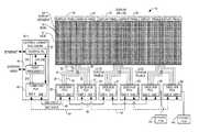
- FIG. 1is a block diagram illustrating a LED display system in accordance with the present invention
- FIG. 2is a partial front view of a portion of the LED display depicted in FIG. 1 ;
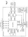
- FIG. 3is a block diagram of a data hub of the LED display system of FIG. 1 ;
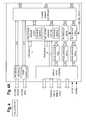
- FIG. 4is a block diagram of the FPGA of the data hub of FIG. 3 ;
- FIG. 5is a block diagram of a master LED module in accordance with the present invention.
- FIG. 6is a block diagram of the FPGA of the master LED module of FIG. 5 ;
- FIG. 7is a block diagram of a slave LED module in accordance with the present invention.
- FIG. 8is a schematic diagram of the pulse width modulation circuit for controlling the intensities of the LEDs of the master and slave modules.
- FIG. 9is a block diagram of a power hub in accordance with one embodiment of the present invention.
- a large scale LED display 10 in accordance with the present inventionfor indoor or outdoor use, has height by width dimensions on the order of 3 m ⁇ 6 m to 24 m ⁇ 32 m or approximately 10 ft. ⁇ 20 ft. to 80 ft. ⁇ 105 ft.
- a display that is approximately 24 m ⁇ 32 mhas 480 pixels ⁇ 640 pixels or a total of 307,200 pixels. Because such a display 10 is so large, only a portion of the display is depicted in FIG. 1 . Moreover, because of its size a robust display is desired.
- the data and power distribution system and method of the present inventionas described in detail below, provide such a robust display wherein failure of a single component will not render the display or even a row or column of the display inoperable.
- Each pixel of the display 10is generated by a module 12 , 14 having two red LEDs 16 , two blue LEDs 18 and two green LEDs 20 mounted in a housing 22 as shown in FIG. 2 .
- Circuitry, described below, within the module housing 22controls the intensities of the red, green and blue LEDs in order to generate pixels of a large number of different colors as is well known in the art.
- each of the modules 12 , 14is depicted in FIG. 2 having pairs of red, green and blue LEDs, the number of red, green and blue LEDs can vary depending upon the flux density of the individual LEDs and/or the spacing between the individual modules. Details of the mechanical and/or structural features of the modules 12 , 14 and the support structure for the display 10 , are disclosed in co-pending patent application Ser. No. 12/001,315, entitled “Large Scale LED Display,” filed concurrently herewith and incorporated herein by reference.
- each master moduleis associated with a group of slave modules in a segment 24 of the display.
- each segment 24has one master module and fifteen slave modules to generate 16 pixels of the display. It should be apparent, however, that the number of slave modules can vary from zero to any number depending upon which aspects of the invention are used.
- the segments 24 of the display 10are linear, extending in a column of the display 10 . However, the segments can alternatively extend in the rows of the display. Moreover, the segments need not be linear but can be formed of a block of modules that include at least one master LED module.
- each column of the displaythere are thirty segments 24 in each column of the display.
- the segments 24are preferably aligned so that each master module is in a row of master modules.
- Each master LED module 12is connected to the adjacent master LED modules in its row to allow direct communication therebetween.
- Each master moduleis also connected to the master modules of adjacent segments in its column to allow direct communication therebetween.
- a master moduleis capable of communicating directly with up to four other master modules as well as each of the fifteen slave modules in the master module segment.
- each panelhas sixteen columns of LED modules, wherein a full height panel has 480 rows of LED modules, although, each of the display panels can have any height and width desired.
- a 480 ⁇ 640 display having display panels with sixteen columnswill employ forty display panels.
- Each display panel 26can receive redundant data to control all of the pixels of the panel 26 from two data hubs, a primary data hub 28 and a redundant data hub 29 .
- Each of the data hubscan provide the data for all of the pixels of two adjacent display panels 26 and 27 by providing two data streams, one data stream for the panel 26 and the other data stream for the panel 27 .
- each data hubis capable of providing redundant data to each display panel on two data cables.
- the data hub 28provides all of the data for the pixels of the display panel 26 on a data cable 30 and can provide redundant data for the panel 26 on a data cable 31 .
- the display panel 26can receive the same data for all of the pixels of the panel from the data hub 29 on data cable 32 or data cable 33 .
- the display panel 26is capable of receiving data on any one of four data cables 30 , 31 , 32 and 33 from the two data hubs 28 and 29 .
- the data hub 28also provides all of the data for the pixels of the display panel 27 on a data cable 34 and can provide redundant data for the panel 27 on a data cable 35 .
- the display panel 27receives the same data from the data hub 29 on data cable 36 or data cable 37 .
- the display panel 27is capable of receiving redundant data on any one of four data cables 34 , 35 , 36 and 37 .
- the redundant data streams received by a display panel 26 on the four data cables 30 - 33are input to four respective master LED modules. However, in a preferred embodiment only one of the four redundant inputs is active to carry pixel data, at one time.
- a primary data hubonly enables the redundant connection if the existing connection fails. Moreover, the redundant data hub only sends data to a panel if it detects that the primary data hub is no longer driving the panel.
- Each of the master modules receiving a data streamextracts the data intended for the master module and the associated slave modules in its segment.
- Each of the master modules receiving a data streamthen outputs the data stream to the adjacent master modules in its row and to the master modules in adjacent segments as discussed in detail below.
- Each master modulecould strip off the data for its segment from a received data stream and send only the remaining portion of the data stream on to other master modules. However, in a preferred embodiment, each master module does not strip off its data from the data stream but acts as a repeater passing the entire received data stream directly to up to three other master modules after extracting a copy of the data for its segment from the data stream.
- the data stream for a display panel 26is thus distributed throughout the panel 26 by each of the master modules 12 . Because a master module 12 can receive a data stream from up to four other master modules 12 , failure of one or two master modules will not render the display or even an entire column or row of the display inoperable as in prior art systems. Failure of one master module will affect only sixteen of the 307,200 pixels of a 480 ⁇ 640 pixel display 10 . Failure of one slave 14 module will not affect any other modules of the display 10 .
- the system for controlling the display 10includes a main controller 40 .
- the main controller 40includes a central processing unit (CPU) 42 and associated memory to control and monitor the rest of the display system.
- the main controller 40also includes a video processor 44 .
- the video processor 44may receive uncompressed video or compressed video in any format such as MPEG4 or H.264, etc.
- the video processor 44scales the video to the size of the display 10 and provides uncompressed digital video in a conventional raster scan format to a communication hub 46 .
- the communication hub 46includes a memory such as SRAM and a micro-controller. Raster scan video data is stored in the memory of the communication hub 46 .
- each packet of data sent by the communication hub 46 to the data hubs 28 and 29includes a column header identifying the column number of the data in the packet, followed by a segment header that includes the segment number associated with the data.
- the segment headermay also include a control word that identifies a status request and a pixel count that identifies the number of pixels in a segment. The pixel count indicates the number of bytes of pixel data to follow for each of the modules in a segment.
- the segment pixel datafollows the segment header wherein three bytes of data are sent for each pixel to control the intensities of the respective red, green and blue LEDs of the pixel.
- the communication hub or the data hubscan send different types of packets to the display panel wherein the packet includes a packet type identifier.
- the different type of packets that can be sentinclude a master module enumeration message; display data and/or control messages; master module status requests; and slave module status requests.
- Packets that include pixel datainclude a master module address formed of the master module's column number and segment number and at least one slave module address followed by the LED data for the slave module. It is noted that each master module includes a slave module micro-controller circuit for controlling the LEDs of the master module.
- the slave module micro-controller in the master modulehas a slave module address.
- the master modulehas both a master module address and an associate slave address for its LED micro-controller.
- the display data packetalso includes a command that further identifies the following data as being display data for an individual master or slave module or display data for a segment of modules. This alternative packet structure allows greater flexibility so that different packet types with various commands can be sent to a display panel.
- the communication hub 46sends redundant data streams containing the data for the entire display 10 on a pair of GbE links 48 and 49 that are connected to respective data hubs 28 and 29 .
- Each data hubis responsive to a received data stream to extract the columns of data for the two panels that the data hub controls, the data hub passing the remaining portion or the entire data stream as received on to another data hub.
- the data streamis thus distributed from data hub to data hub for all of the data hubs in the display system.
- the data hub 28receives a data stream containing the data for the entire display 10 on the GbE link 48 .
- the data hub 28extracts the data for columns 1 - 16 for the display panel 26 and the data for columns 17 - 32 for display panel 27 and then passes the entire data stream on a GbE link 50 to a data hub 51 .
- the data hub 51in turn extracts the data for the next pair of display panels in the sequence, display panels 52 and 53 and then passes the entire data stream to the data hub 56 .
- the data hub 29receives the data stream containing the data for the entire display 10 on the GbE link 49 .
- the data hub 29extracts the data for columns 1 - 16 for the display panel 26 and the data for columns 17 - 32 for display panel 27 and then passes the entire data stream on the GbE link 54 to the data hub 55 .
- the data hub 55extracts the data for the display panels 52 and 53 and passes the entire data stream on to data hub 58 .
- the distribution of the data streamcontinues to the pairs of data hubs until all of the data hubs controlling the display panel 10 have received their data for a frame of video.
- the data distributionthen continues for all of the frames of a video presentation.
- Each data hubincludes a dual GbE interface 60 which is connected to either the communication hub 46 or an upstream data hub, as well as a downstream data hub as described above.
- a received data streamis stored by a data hub FPGA 62 in a SRAM 64 .
- the data hub FPGA 62stores data in and reads data from the SRAM 64 in accordance with software/firmware stored in a flash memory 68 .
- the data hubincludes four data ports 70 - 73 for the LVDS cables that connect the data hub to a pair of display panels.
- the ports 70 and 71will be connected to the LVDS cables 30 and 31 for two master LED modules of the panel 26 and the data ports 72 and 73 will be connected to the LVDS cables 34 and 35 for two master LED modules of the display panel 27 .
- Each data hubin addition to transferring video data to its associated pair of display panels, also performs diagnostics for its display panels. Power is supplied to the data hub from an associated power hub as depicted in FIG. 9 .
- the data hubwill monitor the status of its associated power hub and will communicate the status of its associated power hub and its associated display panels to the communication hub 46 of the main controller 40 .
- the data hub FPGA 62as shown in detail in FIG. 4 , includes a shared memory controller with direct memory access (DMA) for transferring video data and messages, for the display panels and main controller 40 , in and out of the SRAM 64 .
- DMAdirect memory access
- each of the master LED modules 12includes a micro-controller 80 and associated drive circuits shown in FIG. 8 for controlling the intensities of the red LEDs 82 , green LEDs 84 and blue LEDs 86 of the master module 12 .
- the micro-controller 80 of the master module 12controls the LEDs in the same manner as described in detail below for the slave modules 14 and the micro-controller 80 has an associated slave module address as noted above.
- the micro-controller 80 of the master module 12programs the master module FPGA controller 90 in accordance with the configuration information stored in a flash memory 88 .
- Each master LED module 12includes four bidirectional ports, a north port 91 , an east port 92 , a south port 93 and a west port 94 that are coupled to the module's FPGA controller 90 .
- the controller 90 of the master modulecommunicates with each of its associated slave modules through a common I2C serial bus 92 that is connected to the north port 91 .
- the controller 90communicates with up to four other master LED modules 12 through respective LVDS cables connected to the ports 91 , 92 , 93 and 94 .
- Power for the master LED module 12is received from power cables coupled to the module 12 from a power hub as shown in FIG. 9 through a data hub.
- the power received by a master LED moduleis unregulated and is in the range of 15-36 Volts D.C.
- a switching voltage regulator 96 in the module 12steps the input voltage down to a regulated 9V.
- the rail voltage of 9Vis distributed to the slave LED modules in the master module's segment via the north port 91 .
- a block 98 within the master module 12includes another switching voltage regulator that steps the 9V rail down to 3.3V.
- a pair of linear voltage regulatorsalso within the block 98 step the 3.3V down to 2.5V and 1.2V for the master LED module FPGA controller 90 .
- the FPGA controller 90 as shown in FIG. 6includes a downstream packet multiplexer 100 .
- the downstream packet multiplexer 100is coupled to the respective data ports 91 - 94 through input filters asynchronous serial receivers and data decoders 100 - 104 and input filters 105 - 108 .
- the receivers and decoders 100 - 104receive and recover a data stream on a respective port.
- Each input filter 105 - 108identifies an input stream as a hub stream, i.e. data originating from a data hub for downstream distribution or as a MLM stream, i.e. data originating from a master module such as a response or reply packet to be sent back to a data hub.
- the input filter 105 - 108forwards packets on only if the input stream is valid.
- the downstream packet multiplexer 100selects one of the four input ports as the upstream port and forwards packets originating from a data hub from the selected upstream port. If the packet originating from the data hub is an enumeration packet the packet is forwarded to a master module enumeration state machine, e.g. controller/processor 112 .
- a master module enumeration state machine 112performs an enumeration process to determine the location of the master LED module within a display panel 26 and thus, an address for the master LED module so that each pixel of the display can be individually addressed to deliver data thereto.
- the enumeration process performed by the state machine 112is as follows. On power up of the display 10 , the master LED module address registers that hold the segment number and column number of the master module in an enumeration state machine 112 are zero.
- the first master LED module enumeration message receivedis generated by the data hub and simply contains the segment number and column number of the hub. The enumeration message from the data hub is sent to only one master LED module.
- the enumeration messagewill be sent to another master LED module that is directly connected to a data hub.
- a master LED modulereceives an enumeration message it determines its own location, i.e. address, in the display as follows. If the message is received on the master module's south port 93 , the enumeration state machine 112 sets the master module's segment number equal to the segment number in the received message incremented by one and sets the master module's column number equal to the column number in the received message.
- the enumeration state machine 112sets the module's segment number equal to the segment number in the received message and sets the master module's column number to the column number in the received message incremented by one. If the enumeration message is received via the north port 91 of the module, the enumeration state machine 112 sets the module's segment number equal to the segment number in the received message decremented by one and sets the column number to the column number in the received message.
- the enumeration state machine 112sets the module's segment number equal to the segment number in the received message and sets the column number to the column number in the received message as decremented by one.
- the segment number and column number determined for the master moduleare stored in the module's address register.
- the enumeration state machine 112overwrites the segment number and column number in the received enumeration message with the segment number and column number determined for its module.
- the enumeration state machine 112then forwards this revised enumeration message out to three other master modules on three of the bidirectional ports 91 - 94 , i.e. on all of the bidirectional ports 91 - 94 other than the one port 91 - 94 on which the enumeration message was first received.
- one input port 91 - 94is selected at any time as the source of display data and messages from a data hub, this selected input port being designated as the upstream port.
- the downstream packet multiplexer 100selects as the upstream port, the port whose associated input filter first declares or identifies a valid hub stream, i.e. a stream originating from a data hub.
- the three remaining ports 91 - 94are designated as downstream ports.
- the upstream portis used in the downstream packet multiplexer 100 to determine which hub stream to forward and is used in an upstream packet multiplexer 109 to determine which ports to monitor for upstream packets.
- the upstream packet multiplexer 109forwards MLM streams back towards the data hub.
- a hub stream that is received via the selected upstream portis forwarded and output from the master LED module via the three downstream ports to three other master LED modules if the upstream port selection is valid and the stream is a valid hub stream.
- MLM reply messagesthat are received on any of the three downstream ports are output from the module 12 on the selected upstream port if the upstream port selection is valid and the stream is a valid MLM stream.
- Two conditionswill trigger the downstream packet multiplexer 105 to select a different upstream port: the loss of synchronization from the data decoder associated with the initial upstream port or the stream type being received on the current upstream port changes to a valid MLM stream.
- the downstream packet multiplexer 100waits 1 msec and performs the upstream port selection process as described above.
- a master packet processor 113processes data hub packets that are addressed to the master module or that have segment and column header fields that are all zeros, i.e. a broadcast message such as used in the enumeration process.
- a master packet processor 113 of the master LED modulescan extract video data for its segment from a data stream.
- the master packet processor 113 of a master LED moduleextracts video data for its segment by detecting the master module's address in a received data packet and processes those data packets addressed to the master module.
- the extracted pixel datais written by the packet processor 113 to a message FIFO 108 .
- a command byteis written to a command FIFO 115 .
- the command FIFO 115also holds information indicating whether a received message ended with a normal end of packet indication or not and a message byte count indicating the number of bytes in the message FIFO 114 for the received message.
- An I2C controller 116reads and processes messages from the message FIFO 114 in response to commands in the command FIFO 115 .
- the controllersends valid messages onto the I2C bus 92 so the message is broadcast to the master module micro-controller 80 and to each of the slave modules of the segment.
- the controller 116sends slave LED module response data or status reply messages to the upstream processor 117 .
- the upstream processor 117 of the FPGA controller 90maintains master LED module status information including the status of all four of the receivers 101 - 104 .
- the upstream processor 117caches slave module status information received on the I2C bus 92 in an internal RAM.
- the upstream processor 117generates the master module and slave module status reply messages in response to strobes from the packet processor 113 .
- the processor 117also forwards status reply messages received from other master modules via the downstream ports and the upstream packet multiplexer 109 so that the status of each of the modules of a display panel are eventually transmitted back to the data hub for the display panel.
- Status messagesare coupled to an upstream transmitter encoder 118 from the upstream processor 117 via an upstream FIFO 119 wherein the upstream transmitter encoder 118 is coupled to the transmitter 121 - 124 of the selected upstream port 91 - 94 .
- the state machine 112couples a hub stream received via the master module's upstream port to the three designated downstream transmitters 121 - 124 associated with the three downstream ports 91 - 94 via a downstream FIFO 125 and a downstream transmitter encoder 126 .
- the master LED modules 12are connected in a mesh configuration wherein each of the master modules 12 , except those along an edge of a display panel 26 , are connected to four other master LED modules 12 .
- Each of the master modules 12 in this setis capable of receiving data from any of the four other master LED modules to which it is connected.
- each of the master modules 12responds to a data stream from the one master module that is connected to its upstream port.
- a given master modulewill respond to the data stream from a master module connected to its upstream port to extract data therefrom and to send the received data stream out to the three other master LED modules that are connected to a respective one of its three downstream ports.
- the upstream port of the given master moduleis changed by its downstream packet multiplexer 100 to a different port so that the given master LED module can receive a data stream from one of the other three master LED modules to which it is connected. Because each master LED module can receive data from up to four other master modules, the data distribution scheme of the present invention is extremely robust.
- FIG. 7illustrates the structure of the slave LED modules 14 .
- Each of the slave LED modules 14includes a linear voltage regulator 131 that is responsive to the 9V from the associated master LED module to step down that rail voltage to 3.3V.
- Each slave module 14also includes a micro-controller 130 that generates a red pulse width modulation (PWM) control signal, a green PWM control signal and a blue PWM control signal that are coupled to respective drive and sense circuits 132 , 133 and 134 .
- the drive and sense circuit 132is coupled to the pair of red LEDs 136 of the slave module 14 for controlling the intensity of the red LEDs.
- the circuit 133is coupled to a pair of green LEDs 138 of the slave module 14 and the circuit 134 is coupled to a pair of blue LEDs 140 of the slave module 14 to control the intensities of the respective green and blue LEDs.
- Each of the drive and sense circuits 132 , 133 and 134is depicted in detail in FIG. 8 .
- the micro-controller 130outputs a PWM control signal to drive the gate of a MOSFET 142 through a series limiting resistor 144 .
- the micro-controller 130drives the gate of the MOSFET 142 high, the MOSFET 142 switches on, allowing current to flow through the LEDs 136 .
- the transistor 148 connected to the gate of the MOSFET 142turns on, keeping the voltage from the source resistor from increasing any further.
- the values of the resistors 150 and 152are the same.
- the frequency of the PWM control signalis preferably on the order of 10 kHz. It is noted that the micro-controller 80 of the master LED modules controls the LEDs of the master module via the same drive and sense circuit depicted in FIG. 8 .
- the micro-controllers 80 and 130 of the master and slave moduleshave analog inputs to receive a red sense signal, a green sense signal and a blue sense signal. The micro-controllers monitor these sense signals to determine whether the respective LEDs are on or off. This information is included in the status information for each of slave and master LED modules 14 and 12 .
- Each of the micro-controllers 80 and 130also includes a built in temperature sensor that senses the temperature of the entire master module or slave module. A micro-controller may turn off the LEDs of a module if the temperature sensed for the module exceeds a predetermined limit.
- FIG. 9is a block diagram of a power hub in accordance with the present invention.
- a power hubFor a display 10 having a height of 480 pixels, one power hub is provided for each display panel having sixteen columns of pixels.
- a panel of half of the full heighti.e. a height of 240 pixels, one power hub is provided to supply the power for two adjacent display panels each, having sixteen columns of pixels.
- a panel having a height of one quarter of a full height panel, i.e. a height of 120 pixelsone power hub can supply the power for four adjacent display panels each having sixteen columns.
- Each of the power hubs 160converts three-phase A.C. to a rectified and filtered D.C. voltage of approximately 30V. No regulated power is provided by the power hub 160 .
- the voltage regulation for the display 10is provided by the switching voltage regulators in the master LED modules of the display and the linear regulators in the slave LED modules.
- Each power hubincludes a transformer 162 that preferably has phase shifted windings and input voltage selection tabs.
- the transformer 162receives the three-phase A.C. input via a three-phase breaker 164 and a main relay 166 .
- the transformer 162is also coupled to the three-phase breaker 164 via soft start resistors 168 and a soft start relay 169 .
- the output of the transformeris coupled to a pair of three-phase bridge rectifiers 170 and 171 .
- the outputs of the rectifiers 170 and 171are coupled to a respective pair of clamped filter inductors 172 and 173 , the outputs of which are coupled to damped output capacitors 174 .
- the capacitors 174are coupled to four D.C. output connectors 176 via sixty four D.C. circuit breakers 178 .
- the four D.C. output connectors 176provide sixteen D.C. power drives for each of the sixteen columns of a full height, 480 pixel display panel.
- the power hub 160also includes an auxiliary transformer 180 that is coupled to one phase of the A.C. input via a one-phase breaker 182 .
- a supervisory and control board 184monitors all of the sensors of the power hub as well as the voltage from the auxiliary transformer 180 . Initially, the main relay 166 and the soft start relay 169 are open. If the supervisory and control board 184 detects any incorrect signal via the auxiliary transformer voltage 180 , start up is aborted. If the signals are correct, the control 184 initially closes the soft start relay 169 , the relays for the fans 186 and the relays for a strip heaters 188 . The controls 184 also allows 24V to be applied to external logic at this time. At this stage, the capacitors 174 can charge up slowly.
- the control 184opens the soft start relay 169 and the start up is aborted. If the correct voltage is reached, the main relay 166 is closed and the soft start relay 169 is opened. At this point, the display 10 can be powered up.
- the strip heaters 188are employed to drive out humidity to prevent unwanted conductive paths leading to shorts or shock hazards. These heaters are controlled by the supervisory and control board 184 so that the heaters 188 are only on when needed.
- the fans 186provide cooling for the power hub 160 .
- the fanshave speed sensors to which the supervisory and control board 184 is responsive to provide a warning of impending fan failure.
- Thermostats 190are provided for the heat sinks and magnetics of the power hub 160 .
- the supervisory and control board 184includes a temperature sensor so as to provide an early indication of overheating. If the temperature of the power hub 160 exceeds a predetermined level, the supervisory and control board 184 will turn off the main relay 166 to stop overheating. The supervisory and control board 184 will also continuously monitor the D.C. output voltage of the power hub 160 . If the control 184 detects output voltages that are too high, the control 184 will open the main relay 166 .
Landscapes
- Engineering & Computer Science (AREA)
- Theoretical Computer Science (AREA)
- Physics & Mathematics (AREA)
- General Physics & Mathematics (AREA)
- Multimedia (AREA)
- Human Computer Interaction (AREA)
- General Engineering & Computer Science (AREA)
- Computer Hardware Design (AREA)
- Control Of Indicators Other Than Cathode Ray Tubes (AREA)
- Control Of El Displays (AREA)
- Digital Computer Display Output (AREA)
Abstract
Description
Claims (26)
Priority Applications (10)
| Application Number | Priority Date | Filing Date | Title |
|---|---|---|---|
| US12/001,276US8558755B2 (en) | 2007-12-11 | 2007-12-11 | Large scale LED display system |
| CN2008801266236ACN101952878B (en) | 2007-12-11 | 2008-12-03 | Large scale led display system |
| EP08859399AEP2232472A4 (en) | 2007-12-11 | 2008-12-03 | Large scale led display system |
| MX2010006486AMX2010006486A (en) | 2007-12-11 | 2008-12-03 | Large scale led display system. |
| BRPI0819879-9ABRPI0819879A2 (en) | 2007-12-11 | 2008-12-03 | Large scale LED display system. |
| JP2010538050AJP5592799B2 (en) | 2007-12-11 | 2008-12-03 | Large display system |
| PCT/US2008/085316WO2009076114A1 (en) | 2007-12-11 | 2008-12-03 | Large scale led display system |
| CA2709162ACA2709162A1 (en) | 2007-12-11 | 2008-12-03 | Large scale led display system |
| US13/052,912US9135838B2 (en) | 2007-12-11 | 2011-03-21 | Large scale LED display |
| US14/178,023US9378671B2 (en) | 2007-12-11 | 2014-02-11 | Large scale LED display |
Applications Claiming Priority (1)
| Application Number | Priority Date | Filing Date | Title |
|---|---|---|---|
| US12/001,276US8558755B2 (en) | 2007-12-11 | 2007-12-11 | Large scale LED display system |
Publications (2)
| Publication Number | Publication Date |
|---|---|
| US20090146931A1 US20090146931A1 (en) | 2009-06-11 |
| US8558755B2true US8558755B2 (en) | 2013-10-15 |
Family
ID=40721112
Family Applications (1)
| Application Number | Title | Priority Date | Filing Date |
|---|---|---|---|
| US12/001,276Expired - Fee RelatedUS8558755B2 (en) | 2007-12-11 | 2007-12-11 | Large scale LED display system |
Country Status (8)
| Country | Link |
|---|---|
| US (1) | US8558755B2 (en) |
| EP (1) | EP2232472A4 (en) |
| JP (1) | JP5592799B2 (en) |
| CN (1) | CN101952878B (en) |
| BR (1) | BRPI0819879A2 (en) |
| CA (1) | CA2709162A1 (en) |
| MX (1) | MX2010006486A (en) |
| WO (1) | WO2009076114A1 (en) |
Cited By (13)
| Publication number | Priority date | Publication date | Assignee | Title |
|---|---|---|---|---|
| US20120007898A1 (en)* | 2009-01-30 | 2012-01-12 | Ndsu Research Foundation | Infra-extensible led array controller for light emission and/or light sensing |
| US8824124B1 (en)* | 2013-03-16 | 2014-09-02 | ADTI Media, LLC | Modular wire harness arrangements and methods of using same for backside to frontside power and data distribution safety schemes |
| US8824125B1 (en)* | 2013-03-16 | 2014-09-02 | ADTI Media, LLC | Modular installation and conversion kit for electronic sign structure and method of using same |
| US20140259634A1 (en)* | 2013-03-16 | 2014-09-18 | ADTI Media, LLC | Sign construction with sectional sign assemblies and installation kit and method of using same |
| US9069519B1 (en) | 2013-12-31 | 2015-06-30 | Ultravision Technologies, Llc | Power and control system for modular multi-panel display system |
| US9164722B2 (en) | 2013-12-31 | 2015-10-20 | Ultravision Technologies, Llc | Modular display panels with different pitches |
| US9207904B2 (en) | 2013-12-31 | 2015-12-08 | Ultravision Technologies, Llc | Multi-panel display with hot swappable display panels and methods of servicing thereof |
| US9311847B2 (en) | 2014-07-16 | 2016-04-12 | Ultravision Technologies, Llc | Display system having monitoring circuit and methods thereof |
| US9416551B2 (en) | 2013-12-31 | 2016-08-16 | Ultravision Technologies, Llc | Preassembled display systems and methods of installation thereof |
| US20160307479A1 (en)* | 2013-03-16 | 2016-10-20 | ADTI Media, LLC | Sign construction with sectional sign assemblies and installation kit and method of using same |
| US9852666B2 (en) | 2013-03-16 | 2017-12-26 | Adti Media Llc | Full height sectional sign assembly and installation kit and method of using same |
| DE102016216381A1 (en) | 2016-08-31 | 2018-03-01 | Robert Bosch Gmbh | Display unit, display device comprising at least one display unit and use of the display unit and the display device |
| US10061553B2 (en) | 2013-12-31 | 2018-08-28 | Ultravision Technologies, Llc | Power and data communication arrangement between panels |
Families Citing this family (21)
| Publication number | Priority date | Publication date | Assignee | Title |
|---|---|---|---|---|
| JP2009037221A (en)* | 2007-07-06 | 2009-02-19 | Semiconductor Energy Lab Co Ltd | LIGHT EMITTING DEVICE, ELECTRONIC DEVICE, AND LIGHT EMITTING DEVICE DRIVE METHOD |
| US8922458B2 (en)* | 2007-12-11 | 2014-12-30 | ADTI Media, LLC | Data and power distribution system and method for a large scale display |
| US8599108B2 (en)* | 2007-12-11 | 2013-12-03 | Adti Media, Llc140 | Large scale LED display |
| US8766880B2 (en)* | 2007-12-11 | 2014-07-01 | Adti Media, Llc140 | Enumeration system and method for a LED display |
| US8648774B2 (en)* | 2007-12-11 | 2014-02-11 | Advance Display Technologies, Inc. | Large scale LED display |
| WO2009109853A2 (en)* | 2008-03-07 | 2009-09-11 | Ek3 Technologies, Inc | Fault detection and correction for single and multiple media players connected to electronic displays, and related devices, methods and systems |
| US20110140992A1 (en)* | 2009-12-16 | 2011-06-16 | Isign Display Systems Llc (Hangzhou) | LED display |
| CN101923843A (en)* | 2010-07-20 | 2010-12-22 | 广东威创视讯科技股份有限公司 | System and method for realizing redundancy backup of video signals |
| CN202042139U (en)* | 2011-04-22 | 2011-11-16 | 深圳市洲明科技股份有限公司 | Ultrathin box body for LED (light-emitting diode) display screen |
| CN103927947B (en)* | 2014-04-18 | 2017-09-29 | 深圳市洲明科技股份有限公司 | Small space distance LED display screen |
| US10535296B2 (en) | 2015-06-10 | 2020-01-14 | Apple Inc. | Display panel redundancy schemes |
| GB2545490A (en) | 2015-12-18 | 2017-06-21 | Dst Innovations Ltd | Display device and apparatus |
| KR102197116B1 (en) | 2016-03-03 | 2020-12-31 | 한국전자통신연구원 | Display device comprising power delivery network controller and display power management method using the same |
| CN107306463B (en)* | 2016-04-21 | 2019-05-03 | 矽诚科技股份有限公司 | Two-pin point control lamp string system |
| EP3464999A4 (en) | 2016-05-31 | 2020-01-01 | Anthem Displays, LLC | REDUNDANT DATA SUPPLY SYSTEM AND METHODS |
| CN108109577B (en)* | 2016-12-06 | 2023-05-23 | 广州硅芯电子科技有限公司 | LED system and method for operating an LED system |
| CN109523959B (en)* | 2019-01-02 | 2020-07-28 | 重庆京东方智慧电子系统有限公司 | Power supply circuit and display device |
| CN112585668A (en)* | 2019-07-30 | 2021-03-30 | 西安诺瓦星云科技股份有限公司 | Deconcentrator, LED display system, display screen configuration method and device |
| KR102748801B1 (en) | 2019-11-04 | 2025-01-02 | 삼성전자주식회사 | Display apparatus and control method thereof |
| CN113747206B (en)* | 2020-05-27 | 2024-03-15 | 西安诺瓦星云科技股份有限公司 | Data feedback control method and system, display screen controller and display control card |
| WO2021240221A1 (en)* | 2020-05-29 | 2021-12-02 | Universita' Degli Studi Di Pavia Dipartimento Di Ingegneria Civile E Architettura | A system of smart objects, in particular tiles |
Citations (60)
| Publication number | Priority date | Publication date | Assignee | Title |
|---|---|---|---|---|
| GB2143983A (en) | 1983-07-26 | 1985-02-20 | Ferranti Plc | Large scale display |
| US4782336A (en) | 1983-07-26 | 1988-11-01 | Ferrnati, Plc | Two dimensional visual display |
| US4887074A (en) | 1988-01-20 | 1989-12-12 | Michael Simon | Light-emitting diode display system |
| GB2240686A (en) | 1989-11-24 | 1991-08-07 | Sean Hillen | Modular video display for variable size/shape |
| US5160200A (en) | 1991-03-06 | 1992-11-03 | R & D Molded Products, Inc. | Wedge-base LED bulb housing |
| US5184114A (en) | 1982-11-04 | 1993-02-02 | Integrated Systems Engineering, Inc. | Solid state color display system and light emitting diode pixels therefor |
| US5287353A (en) | 1991-12-23 | 1994-02-15 | Square D Company | Apparatus for generating and sending a serial data packet for controlling a network of single point I/O devices |
| US5317344A (en) | 1989-12-22 | 1994-05-31 | Eastman Kodak Company | Light emitting diode printhead having improved signal distribution apparatus |
| US5406176A (en) | 1994-01-12 | 1995-04-11 | Aurora Robotics Limited | Computer controlled stage lighting system |
| US5410328A (en) | 1994-03-28 | 1995-04-25 | Trans-Lux Corporation | Replaceable intelligent pixel module for large-scale LED displays |
| US5420482A (en) | 1993-02-11 | 1995-05-30 | Phares; Louis A. | Controlled lighting system |
| US5523769A (en)* | 1993-06-16 | 1996-06-04 | Mitsubishi Electric Research Laboratories, Inc. | Active modules for large screen displays |
| US5564819A (en) | 1994-04-04 | 1996-10-15 | Rohm Co., Ltd. | LED lamp and arrangement for mounting LED lamps on a substrate |
| US5636303A (en) | 1995-12-18 | 1997-06-03 | World Precision Instruments, Inc. | Filterless chromatically variable light source |
| US5900850A (en) | 1996-08-28 | 1999-05-04 | Bailey; James Tam | Portable large scale image display system |
| US5924784A (en) | 1995-08-21 | 1999-07-20 | Chliwnyj; Alex | Microprocessor based simulated electronic flame |
| US6009650A (en) | 1995-09-08 | 2000-01-04 | Lamparter; Ronald C. | Illuminated sign assembly |
| US6016038A (en) | 1997-08-26 | 2000-01-18 | Color Kinetics, Inc. | Multicolored LED lighting method and apparatus |
| US6104414A (en)* | 1997-03-12 | 2000-08-15 | Cybex Computer Products Corporation | Video distribution hub |
| US6118426A (en) | 1995-07-20 | 2000-09-12 | E Ink Corporation | Transducers and indicators having printed displays |
| US6211626B1 (en) | 1997-08-26 | 2001-04-03 | Color Kinetics, Incorporated | Illumination components |
| US20020003592A1 (en)* | 2000-07-10 | 2002-01-10 | Hett Charles L. | LCD tile display |
| US6362801B1 (en) | 1998-06-17 | 2002-03-26 | Engineer Lighting, Inc. | Display apparatus |
| US6435459B1 (en) | 1999-10-28 | 2002-08-20 | Dialight Corporation | LED wayside signal for a railway |
| US6498672B2 (en) | 1999-03-30 | 2002-12-24 | Seiko Epson Corporation | Electro-optical device and projection display device including the same |
| US6519395B1 (en) | 2000-05-04 | 2003-02-11 | Northrop Grumman Corporation | Fiber optic array harness |
| US20030051098A1 (en)* | 2001-08-29 | 2003-03-13 | Brant William A. | Modular RAID controller |
| JP2003092195A (en) | 2001-09-18 | 2003-03-28 | Toritsu Tsushin Kogyo Kk | Led display device |
| US20030117347A1 (en) | 2001-12-21 | 2003-06-26 | Koninklijke Philips Electronics N.V. | Active matrix electroluminescent display device |
| US20030146882A1 (en)* | 1997-06-02 | 2003-08-07 | Daichu Denshi Co., Ltd., Fourie, Inc. | Extending type of display apparatus and display system using the same |
| US6608453B2 (en) | 1997-08-26 | 2003-08-19 | Color Kinetics Incorporated | Methods and apparatus for controlling devices in a networked lighting system |
| US20040008155A1 (en) | 2002-07-10 | 2004-01-15 | Eastman Kodak Company | Electronic system for tiled displays |
| US6737983B1 (en) | 1999-10-26 | 2004-05-18 | John Temple | Display board having illuminated elements and method |
| US6777891B2 (en) | 1997-08-26 | 2004-08-17 | Color Kinetics, Incorporated | Methods and apparatus for controlling devices in a networked lighting system |
| US6788011B2 (en) | 1997-08-26 | 2004-09-07 | Color Kinetics, Incorporated | Multicolored LED lighting method and apparatus |
| US6816143B1 (en)* | 1999-11-23 | 2004-11-09 | Koninklijke Philips Electronics N.V. | Self diagnostic and repair in matrix display panel |
| US20040222941A1 (en)* | 2002-12-30 | 2004-11-11 | Wong Mark Yuk-Lun | Multi-display architecture using single video controller |
| US20050017922A1 (en)* | 2003-07-22 | 2005-01-27 | Barco, Naamloze Vennottschap | Method for controlling an organic light-emitting diode display, and display applying this method |
| US20050052375A1 (en) | 2003-09-08 | 2005-03-10 | Bruno Devos | Configurable large-area display system and control unit used therein, and method of operating the display |
| EP1550947A2 (en) | 2003-12-23 | 2005-07-06 | Barco N.V. | Configurable tiled emissive display |
| US20050264471A1 (en)* | 2004-05-21 | 2005-12-01 | Shunpei Yamazaki | Display device and electronic apparatus having the same |
| JP2006005830A (en) | 2004-06-21 | 2006-01-05 | Mitsubishi Electric Corp | Video display system |
| US6998650B1 (en) | 2005-03-17 | 2006-02-14 | Jiahn-Chang Wu | Replaceable light emitting diode module |
| US20060039142A1 (en) | 2004-08-23 | 2006-02-23 | Temple John W | Led net display |
| US20060132048A1 (en) | 2004-12-16 | 2006-06-22 | Telegen Corporation | Light emitting device and associated methods of manufacture |
| US7071620B2 (en) | 2003-09-08 | 2006-07-04 | Barco, Naamloze Vennootschap | Display pixel module for use in a configurable large-screen display application and display with such pixel modules |
| US20060164587A1 (en)* | 2005-01-25 | 2006-07-27 | Se-Chun Oh | Display panel assembly and display apparatus having the same |
| US20060241878A1 (en) | 2002-12-10 | 2006-10-26 | Infineon Technologies Ag | Surface paneling module, surface paneling module arrangement and method for determining the distence of surface paneling modules of the surface paneling module arrangement to at least one reference position, processor arrangement, textile fabric structure and surface paneling structure |
| US20060256033A1 (en)* | 2005-05-13 | 2006-11-16 | Chan Victor G | Method and apparatus for displaying an image on at least two display panels |
| US7221104B2 (en) | 1997-08-26 | 2007-05-22 | Color Kinetics Incorporated | Linear lighting apparatus and methods |
| US20070115666A1 (en) | 2004-09-23 | 2007-05-24 | Thomas James G | Illumination system |
| US20070241988A1 (en)* | 2003-12-31 | 2007-10-18 | Zerphy Byron L | Dynamic message sign display panel error detection, correction, and notification |
| JP2007298753A (en) | 2006-04-28 | 2007-11-15 | Matsushita Electric Ind Co Ltd | Large video display device |
| US20070279314A1 (en)* | 2006-06-06 | 2007-12-06 | Brown Brent W | Front and rear removable panel for electronic displays |
| WO2007138494A1 (en) | 2006-05-24 | 2007-12-06 | Koninklijke Philips Electronics, N.V. | Method and apparatus for auto-commissioning of led based display configurations |
| US20080316188A1 (en)* | 2007-06-20 | 2008-12-25 | Tovis Co., Ltd. | Liquid crystal display comprising driving circuit unit |
| US20090027303A1 (en)* | 2007-07-25 | 2009-01-29 | Arthur Alan R | Display apparatus with resistor multiplexer |
| US20090096711A1 (en)* | 2007-10-15 | 2009-04-16 | Samsung Electronics Co., Ltd. | Display device and driving method thereof |
| US7616635B2 (en)* | 2006-09-29 | 2009-11-10 | Intel Corporation | Address mapping for data packet routing |
| WO2010059431A1 (en) | 2008-11-19 | 2010-05-27 | Advance Display Technologies, Inc. | Large scale led display |
Family Cites Families (3)
| Publication number | Priority date | Publication date | Assignee | Title |
|---|---|---|---|---|
| US621626A (en)* | 1899-03-21 | Pole or thill coupling | ||
| US478336A (en)* | 1892-07-05 | Otto kissling | ||
| US6333750B1 (en)* | 1997-03-12 | 2001-12-25 | Cybex Computer Products Corporation | Multi-sourced video distribution hub |
- 2007
- 2007-12-11USUS12/001,276patent/US8558755B2/ennot_activeExpired - Fee Related
- 2008
- 2008-12-03CACA2709162Apatent/CA2709162A1/ennot_activeAbandoned
- 2008-12-03EPEP08859399Apatent/EP2232472A4/ennot_activeWithdrawn
- 2008-12-03MXMX2010006486Apatent/MX2010006486A/enactiveIP Right Grant
- 2008-12-03WOPCT/US2008/085316patent/WO2009076114A1/enactiveApplication Filing
- 2008-12-03CNCN2008801266236Apatent/CN101952878B/ennot_activeExpired - Fee Related
- 2008-12-03JPJP2010538050Apatent/JP5592799B2/ennot_activeExpired - Fee Related
- 2008-12-03BRBRPI0819879-9Apatent/BRPI0819879A2/ennot_activeIP Right Cessation
Patent Citations (64)
| Publication number | Priority date | Publication date | Assignee | Title |
|---|---|---|---|---|
| US5184114A (en) | 1982-11-04 | 1993-02-02 | Integrated Systems Engineering, Inc. | Solid state color display system and light emitting diode pixels therefor |
| US4782336A (en) | 1983-07-26 | 1988-11-01 | Ferrnati, Plc | Two dimensional visual display |
| GB2143983A (en) | 1983-07-26 | 1985-02-20 | Ferranti Plc | Large scale display |
| US4887074A (en) | 1988-01-20 | 1989-12-12 | Michael Simon | Light-emitting diode display system |
| GB2240686A (en) | 1989-11-24 | 1991-08-07 | Sean Hillen | Modular video display for variable size/shape |
| US5317344A (en) | 1989-12-22 | 1994-05-31 | Eastman Kodak Company | Light emitting diode printhead having improved signal distribution apparatus |
| US5160200A (en) | 1991-03-06 | 1992-11-03 | R & D Molded Products, Inc. | Wedge-base LED bulb housing |
| US5287353A (en) | 1991-12-23 | 1994-02-15 | Square D Company | Apparatus for generating and sending a serial data packet for controlling a network of single point I/O devices |
| US5420482A (en) | 1993-02-11 | 1995-05-30 | Phares; Louis A. | Controlled lighting system |
| US5523769A (en)* | 1993-06-16 | 1996-06-04 | Mitsubishi Electric Research Laboratories, Inc. | Active modules for large screen displays |
| US5406176A (en) | 1994-01-12 | 1995-04-11 | Aurora Robotics Limited | Computer controlled stage lighting system |
| US5410328A (en) | 1994-03-28 | 1995-04-25 | Trans-Lux Corporation | Replaceable intelligent pixel module for large-scale LED displays |
| US5564819A (en) | 1994-04-04 | 1996-10-15 | Rohm Co., Ltd. | LED lamp and arrangement for mounting LED lamps on a substrate |
| US6118426A (en) | 1995-07-20 | 2000-09-12 | E Ink Corporation | Transducers and indicators having printed displays |
| US5924784A (en) | 1995-08-21 | 1999-07-20 | Chliwnyj; Alex | Microprocessor based simulated electronic flame |
| US6009650A (en) | 1995-09-08 | 2000-01-04 | Lamparter; Ronald C. | Illuminated sign assembly |
| US5636303A (en) | 1995-12-18 | 1997-06-03 | World Precision Instruments, Inc. | Filterless chromatically variable light source |
| US5900850A (en) | 1996-08-28 | 1999-05-04 | Bailey; James Tam | Portable large scale image display system |
| US6104414A (en)* | 1997-03-12 | 2000-08-15 | Cybex Computer Products Corporation | Video distribution hub |
| US20030146882A1 (en)* | 1997-06-02 | 2003-08-07 | Daichu Denshi Co., Ltd., Fourie, Inc. | Extending type of display apparatus and display system using the same |
| US7221104B2 (en) | 1997-08-26 | 2007-05-22 | Color Kinetics Incorporated | Linear lighting apparatus and methods |
| US6211626B1 (en) | 1997-08-26 | 2001-04-03 | Color Kinetics, Incorporated | Illumination components |
| US7253566B2 (en) | 1997-08-26 | 2007-08-07 | Color Kinetics Incorporated | Methods and apparatus for controlling devices in a networked lighting system |
| US6150774A (en) | 1997-08-26 | 2000-11-21 | Color Kinetics, Incorporated | Multicolored LED lighting method and apparatus |
| US6806659B1 (en) | 1997-08-26 | 2004-10-19 | Color Kinetics, Incorporated | Multicolored LED lighting method and apparatus |
| US6788011B2 (en) | 1997-08-26 | 2004-09-07 | Color Kinetics, Incorporated | Multicolored LED lighting method and apparatus |
| US6777891B2 (en) | 1997-08-26 | 2004-08-17 | Color Kinetics, Incorporated | Methods and apparatus for controlling devices in a networked lighting system |
| US6608453B2 (en) | 1997-08-26 | 2003-08-19 | Color Kinetics Incorporated | Methods and apparatus for controlling devices in a networked lighting system |
| US6016038A (en) | 1997-08-26 | 2000-01-18 | Color Kinetics, Inc. | Multicolored LED lighting method and apparatus |
| US6362801B1 (en) | 1998-06-17 | 2002-03-26 | Engineer Lighting, Inc. | Display apparatus |
| US6498672B2 (en) | 1999-03-30 | 2002-12-24 | Seiko Epson Corporation | Electro-optical device and projection display device including the same |
| US6737983B1 (en) | 1999-10-26 | 2004-05-18 | John Temple | Display board having illuminated elements and method |
| US6435459B1 (en) | 1999-10-28 | 2002-08-20 | Dialight Corporation | LED wayside signal for a railway |
| US6816143B1 (en)* | 1999-11-23 | 2004-11-09 | Koninklijke Philips Electronics N.V. | Self diagnostic and repair in matrix display panel |
| US6519395B1 (en) | 2000-05-04 | 2003-02-11 | Northrop Grumman Corporation | Fiber optic array harness |
| US20020003592A1 (en)* | 2000-07-10 | 2002-01-10 | Hett Charles L. | LCD tile display |
| US20030051098A1 (en)* | 2001-08-29 | 2003-03-13 | Brant William A. | Modular RAID controller |
| JP2003092195A (en) | 2001-09-18 | 2003-03-28 | Toritsu Tsushin Kogyo Kk | Led display device |
| US20030117347A1 (en) | 2001-12-21 | 2003-06-26 | Koninklijke Philips Electronics N.V. | Active matrix electroluminescent display device |
| US20040008155A1 (en) | 2002-07-10 | 2004-01-15 | Eastman Kodak Company | Electronic system for tiled displays |
| US20060241878A1 (en) | 2002-12-10 | 2006-10-26 | Infineon Technologies Ag | Surface paneling module, surface paneling module arrangement and method for determining the distence of surface paneling modules of the surface paneling module arrangement to at least one reference position, processor arrangement, textile fabric structure and surface paneling structure |
| US20040222941A1 (en)* | 2002-12-30 | 2004-11-11 | Wong Mark Yuk-Lun | Multi-display architecture using single video controller |
| US20050017922A1 (en)* | 2003-07-22 | 2005-01-27 | Barco, Naamloze Vennottschap | Method for controlling an organic light-emitting diode display, and display applying this method |
| US7071620B2 (en) | 2003-09-08 | 2006-07-04 | Barco, Naamloze Vennootschap | Display pixel module for use in a configurable large-screen display application and display with such pixel modules |
| US20050052375A1 (en) | 2003-09-08 | 2005-03-10 | Bruno Devos | Configurable large-area display system and control unit used therein, and method of operating the display |
| EP1550947A2 (en) | 2003-12-23 | 2005-07-06 | Barco N.V. | Configurable tiled emissive display |
| US20070241988A1 (en)* | 2003-12-31 | 2007-10-18 | Zerphy Byron L | Dynamic message sign display panel error detection, correction, and notification |
| US20050264471A1 (en)* | 2004-05-21 | 2005-12-01 | Shunpei Yamazaki | Display device and electronic apparatus having the same |
| JP2006005830A (en) | 2004-06-21 | 2006-01-05 | Mitsubishi Electric Corp | Video display system |
| US7319408B2 (en) | 2004-08-23 | 2008-01-15 | Advance Display Technologies, Inc. | Led net display |
| US20060039142A1 (en) | 2004-08-23 | 2006-02-23 | Temple John W | Led net display |
| US20070115666A1 (en) | 2004-09-23 | 2007-05-24 | Thomas James G | Illumination system |
| US20060132048A1 (en) | 2004-12-16 | 2006-06-22 | Telegen Corporation | Light emitting device and associated methods of manufacture |
| US20060164587A1 (en)* | 2005-01-25 | 2006-07-27 | Se-Chun Oh | Display panel assembly and display apparatus having the same |
| US6998650B1 (en) | 2005-03-17 | 2006-02-14 | Jiahn-Chang Wu | Replaceable light emitting diode module |
| US20060256033A1 (en)* | 2005-05-13 | 2006-11-16 | Chan Victor G | Method and apparatus for displaying an image on at least two display panels |
| JP2007298753A (en) | 2006-04-28 | 2007-11-15 | Matsushita Electric Ind Co Ltd | Large video display device |
| WO2007138494A1 (en) | 2006-05-24 | 2007-12-06 | Koninklijke Philips Electronics, N.V. | Method and apparatus for auto-commissioning of led based display configurations |
| US20070279314A1 (en)* | 2006-06-06 | 2007-12-06 | Brown Brent W | Front and rear removable panel for electronic displays |
| US7616635B2 (en)* | 2006-09-29 | 2009-11-10 | Intel Corporation | Address mapping for data packet routing |
| US20080316188A1 (en)* | 2007-06-20 | 2008-12-25 | Tovis Co., Ltd. | Liquid crystal display comprising driving circuit unit |
| US20090027303A1 (en)* | 2007-07-25 | 2009-01-29 | Arthur Alan R | Display apparatus with resistor multiplexer |
| US20090096711A1 (en)* | 2007-10-15 | 2009-04-16 | Samsung Electronics Co., Ltd. | Display device and driving method thereof |
| WO2010059431A1 (en) | 2008-11-19 | 2010-05-27 | Advance Display Technologies, Inc. | Large scale led display |
Non-Patent Citations (11)
| Title |
|---|
| European Search Report dated Jan. 27, 2010, Reference No. P91157EP00, Application No./Patent No. 05789062.6-1231 / 1784799 PCT/US2005029599. |
| Extended European Search Report dated Dec. 7, 2010, Application No. EP-08858504, Supplementary European Search Report and European Search Opinion. |
| Extended European Search Report dated Dec. 7, 2010, Application No. EP-08859575, Supplementary European Search Report and European Search Opinion. |
| International Bureau, International Preliminary Report on Patentability and Written Opinion of the International Searching Authority, dated Jun. 24, 2010, International Application No. PCT/US2008/085313. |
| International Bureau, International Preliminary Report on Patentability and Written Opinion of the International Searching Authority, dated Jun. 24, 2010, International Application No. PCT/US2008/085315. |
| International Bureau, International Preliminary Report on Patentability and Written Opinion of the International Searching Authority, dated Jun. 24, 2010, International Application No. PCT/US2008/085316. |
| International Bureau, International Preliminary Report on Patentability and Written Opinion of the International Searching Authority, dated Jun. 24, 2010, International Application No. PCT/US2008/085320. |
| International Searching Authority, International Search Report and Written Opinion of the International Searching Authority, dated Feb. 3, 2009, International Application No. PCT/US/2008/85316. |
| International Searching Authority, International Search Report and Written Opinion of the International Searching Authority, dated Feb. 5, 2009, International Application No. PCT/US/2008/85320. |
| International Searching Authority, International Search Report and Written Opinion of the International Searching Authority, dated Feb. 9, 2009, International Application No. PCT/US/2008/85313. |
| International Searching Authority, International Search Report and Written Opinion of the International Searching Authority, dated Jan. 30, 2009, International Application No. PCT/US/2008/85315. |
Cited By (46)
| Publication number | Priority date | Publication date | Assignee | Title |
|---|---|---|---|---|
| US20120007898A1 (en)* | 2009-01-30 | 2012-01-12 | Ndsu Research Foundation | Infra-extensible led array controller for light emission and/or light sensing |
| US20140259634A1 (en)* | 2013-03-16 | 2014-09-18 | ADTI Media, LLC | Sign construction with sectional sign assemblies and installation kit and method of using same |
| US8824125B1 (en)* | 2013-03-16 | 2014-09-02 | ADTI Media, LLC | Modular installation and conversion kit for electronic sign structure and method of using same |
| US20160307479A1 (en)* | 2013-03-16 | 2016-10-20 | ADTI Media, LLC | Sign construction with sectional sign assemblies and installation kit and method of using same |
| US9047791B2 (en)* | 2013-03-16 | 2015-06-02 | Adti Media, Llc. | Sign construction with sectional sign assemblies and installation kit and method of using same |
| US10210778B2 (en)* | 2013-03-16 | 2019-02-19 | Adti Media Llc | Sign construction with sectional sign assemblies and installation kit and method of using same |
| US10192468B2 (en)* | 2013-03-16 | 2019-01-29 | ADTI Media, LLC | Sign construction with modular installation and conversion kit for electronic sign structure and method of using same |
| US9852666B2 (en) | 2013-03-16 | 2017-12-26 | Adti Media Llc | Full height sectional sign assembly and installation kit and method of using same |
| US9666105B2 (en)* | 2013-03-16 | 2017-05-30 | ADTI Media, LLC | Sign construction with modular wire harness arrangements and methods of using same for backside to frontside power and data distribution schemes |
| US8824124B1 (en)* | 2013-03-16 | 2014-09-02 | ADTI Media, LLC | Modular wire harness arrangements and methods of using same for backside to frontside power and data distribution safety schemes |
| US9536457B2 (en) | 2013-03-16 | 2017-01-03 | Adti Media Llc | Installation kit and method of using same for sign construction with sectional sign assemblies |
| US20160307476A1 (en)* | 2013-03-16 | 2016-10-20 | ADTI Media, LLC | Sign construction with modular wire harness arrangements and methods of using same for backside to frontside power and data distribution schemes |
| US20160307477A1 (en)* | 2013-03-16 | 2016-10-20 | ADTI Media, LLC | Sign construction with modular installation and conversion kit for electronic sign structure and method of using same |
| US9535650B2 (en) | 2013-12-31 | 2017-01-03 | Ultravision Technologies, Llc | System for modular multi-panel display wherein each display is sealed to be waterproof and includes array of display elements arranged to form display panel surface |
| US9916782B2 (en) | 2013-12-31 | 2018-03-13 | Ultravision Technologies, Llc | Modular display panel |
| US9416551B2 (en) | 2013-12-31 | 2016-08-16 | Ultravision Technologies, Llc | Preassembled display systems and methods of installation thereof |
| US9349306B2 (en) | 2013-12-31 | 2016-05-24 | Ultravision Technologies, Llc | Modular display panel |
| US10871932B2 (en) | 2013-12-31 | 2020-12-22 | Ultravision Technologies, Llc | Modular display panels |
| US9226413B1 (en) | 2013-12-31 | 2015-12-29 | Ultravision Technologies, Llc | Integrated data and power cord for use with modular display panels |
| US9513863B2 (en) | 2013-12-31 | 2016-12-06 | Ultravision Technologies, Llc | Modular display panel |
| US9528283B2 (en) | 2013-12-31 | 2016-12-27 | Ultravision Technologies, Llc | Method of performing an installation of a display unit |
| US9207904B2 (en) | 2013-12-31 | 2015-12-08 | Ultravision Technologies, Llc | Multi-panel display with hot swappable display panels and methods of servicing thereof |
| US9195281B2 (en) | 2013-12-31 | 2015-11-24 | Ultravision Technologies, Llc | System and method for a modular multi-panel display |
| US9582237B2 (en) | 2013-12-31 | 2017-02-28 | Ultravision Technologies, Llc | Modular display panels with different pitches |
| US9642272B1 (en) | 2013-12-31 | 2017-05-02 | Ultravision Technologies, Llc | Method for modular multi-panel display wherein each display is sealed to be waterproof and includes array of display elements arranged to form display panel surface |
| US9164722B2 (en) | 2013-12-31 | 2015-10-20 | Ultravision Technologies, Llc | Modular display panels with different pitches |
| US9832897B2 (en) | 2013-12-31 | 2017-11-28 | Ultravision Technologies, Llc | Method of assembling a modular multi-panel display system |
| US9134773B2 (en) | 2013-12-31 | 2015-09-15 | Ultravision Technologies, Llc | Modular display panel |
| US10540917B2 (en) | 2013-12-31 | 2020-01-21 | Ultravision Technologies, Llc | Modular display panel |
| US10410552B2 (en) | 2013-12-31 | 2019-09-10 | Ultravision Technologies, Llc | Modular display panel |
| US9372659B2 (en) | 2013-12-31 | 2016-06-21 | Ultravision Technologies, Llc | Modular multi-panel display system using integrated data and power cables |
| US9940856B2 (en) | 2013-12-31 | 2018-04-10 | Ultravision Technologies, Llc | Preassembled display systems and methods of installation thereof |
| US9978294B1 (en) | 2013-12-31 | 2018-05-22 | Ultravision Technologies, Llc | Modular display panel |
| US9984603B1 (en) | 2013-12-31 | 2018-05-29 | Ultravision Technologies, Llc | Modular display panel |
| US9990869B1 (en) | 2013-12-31 | 2018-06-05 | Ultravision Technologies, Llc | Modular display panel |
| US10061553B2 (en) | 2013-12-31 | 2018-08-28 | Ultravision Technologies, Llc | Power and data communication arrangement between panels |
| US9081552B1 (en) | 2013-12-31 | 2015-07-14 | Ultravision Technologies, Llc | Integrated data and power cord for use with modular display panels |
| US9069519B1 (en) | 2013-12-31 | 2015-06-30 | Ultravision Technologies, Llc | Power and control system for modular multi-panel display system |
| US10248372B2 (en) | 2013-12-31 | 2019-04-02 | Ultravision Technologies, Llc | Modular display panels |
| US10373535B2 (en) | 2013-12-31 | 2019-08-06 | Ultravision Technologies, Llc | Modular display panel |
| US10380925B2 (en) | 2013-12-31 | 2019-08-13 | Ultravision Technologies, Llc | Modular display panel |
| US10706770B2 (en) | 2014-07-16 | 2020-07-07 | Ultravision Technologies, Llc | Display system having module display panel with circuitry for bidirectional communication |
| US9311847B2 (en) | 2014-07-16 | 2016-04-12 | Ultravision Technologies, Llc | Display system having monitoring circuit and methods thereof |
| WO2018041957A1 (en) | 2016-08-31 | 2018-03-08 | Volker Probst | Display unit, display apparatus containing at least one display unit, and use of the display unit and the display apparatus |
| DE102016216381A1 (en) | 2016-08-31 | 2018-03-01 | Robert Bosch Gmbh | Display unit, display device comprising at least one display unit and use of the display unit and the display device |
| US11262047B2 (en) | 2016-08-31 | 2022-03-01 | Volker Probst | Display unit, display apparatus containing at least one display unit, and use of the display unit and the display apparatus |
Also Published As
| Publication number | Publication date |
|---|---|
| MX2010006486A (en) | 2010-10-04 |
| EP2232472A1 (en) | 2010-09-29 |
| CA2709162A1 (en) | 2009-06-18 |
| JP2011508249A (en) | 2011-03-10 |
| US20090146931A1 (en) | 2009-06-11 |
| CN101952878A (en) | 2011-01-19 |
| BRPI0819879A2 (en) | 2015-06-16 |
| WO2009076114A1 (en) | 2009-06-18 |
| CN101952878B (en) | 2013-11-06 |
| EP2232472A4 (en) | 2011-05-25 |
| JP5592799B2 (en) | 2014-09-17 |
Similar Documents
| Publication | Publication Date | Title |
|---|---|---|
| US8558755B2 (en) | Large scale LED display system | |
| US8922458B2 (en) | Data and power distribution system and method for a large scale display | |
| US8766880B2 (en) | Enumeration system and method for a LED display | |
| TWI486094B (en) | Low cost LED driver with improved sequence bus | |
| WO2020056872A1 (en) | Dimming control system and dimming control method for backlight source, and display device | |
| JP2011508249A5 (en) | ||
| US20110001432A1 (en) | Light emitting device with compensation capability | |
| WO2023101344A1 (en) | Display device and control method therefor | |
| JP2017163176A (en) | Multi-screen video display device | |
| HK1188004A (en) | Display system | |
| JP4283807B2 (en) | Video display device | |
| TWI704534B (en) | Control device and traffic lights system | |
| KR20070003423A (en) | Advertisement and emergency induction equipment for subway platforms | |
| KR100818385B1 (en) | Video display device | |
| HK1196460A (en) | Low cost led driver with improved serial bus |
Legal Events
| Date | Code | Title | Description |
|---|---|---|---|
| AS | Assignment | Owner name:ADVANCE DISPLAY TECHNOLOGIES, INC., COLORADO Free format text:ASSIGNMENT OF ASSIGNORS INTEREST;ASSIGNORS:KHARRATI, HAMID;SEFTON, ROBERT J.;BLACK, SHELDON LEE;AND OTHERS;REEL/FRAME:020602/0300 Effective date:20071221 | |
| AS | Assignment | Owner name:DEGEORGE HOLDINGS THREE, LLC, FLORIDA Free format text:SECURITY AGREEMENT;ASSIGNOR:ADVANCE DISPLAY TECHNOLOGIES, INC.;REEL/FRAME:021805/0117 Effective date:20081106 | |
| AS | Assignment | Owner name:ADTI MEDIA, LLC140,FLORIDA Free format text:ASSIGNMENT OF ASSIGNORS INTEREST;ASSIGNOR:ADVANCE DISPLAY TECHNOLOGIES, INC.;REEL/FRAME:024599/0640 Effective date:20100628 Owner name:ADTI MEDIA, LLC140, FLORIDA Free format text:ASSIGNMENT OF ASSIGNORS INTEREST;ASSIGNOR:ADVANCE DISPLAY TECHNOLOGIES, INC.;REEL/FRAME:024599/0640 Effective date:20100628 | |
| STCF | Information on status: patent grant | Free format text:PATENTED CASE | |
| AS | Assignment | Owner name:ADTI MEDIA, LLC, FLORIDA Free format text:CORRECTIVE ASSIGNMENT TO CORRECT THE NAME AND ADDRESS OF THE ASSIGNEE PREVIOUSLY RECORDED ON REEL 024599 FRAME 0640. ASSIGNOR(S) HEREBY CONFIRMS THE ASSIGNMENT OF ASSIGNORS INTEREST;ASSIGNOR:ADVANCE DISPLAY TECHNOLOGIES, INC;REEL/FRAME:034535/0662 Effective date:20100628 | |
| FPAY | Fee payment | Year of fee payment:4 | |
| FEPP | Fee payment procedure | Free format text:MAINTENANCE FEE REMINDER MAILED (ORIGINAL EVENT CODE: REM.); ENTITY STATUS OF PATENT OWNER: SMALL ENTITY | |
| LAPS | Lapse for failure to pay maintenance fees | Free format text:PATENT EXPIRED FOR FAILURE TO PAY MAINTENANCE FEES (ORIGINAL EVENT CODE: EXP.); ENTITY STATUS OF PATENT OWNER: SMALL ENTITY | |
| STCH | Information on status: patent discontinuation | Free format text:PATENT EXPIRED DUE TO NONPAYMENT OF MAINTENANCE FEES UNDER 37 CFR 1.362 | |
| FP | Lapsed due to failure to pay maintenance fee | Effective date:20211015 |