US8558579B2 - Digital glitch filter - Google Patents
Digital glitch filterDownload PDFInfo
- Publication number
- US8558579B2 US8558579B2US13/540,634US201213540634AUS8558579B2US 8558579 B2US8558579 B2US 8558579B2US 201213540634 AUS201213540634 AUS 201213540634AUS 8558579 B2US8558579 B2US 8558579B2
- Authority
- US
- United States
- Prior art keywords
- flip
- signal
- input
- flop
- terminal
- Prior art date
- Legal status (The legal status is an assumption and is not a legal conclusion. Google has not performed a legal analysis and makes no representation as to the accuracy of the status listed.)
- Expired - Fee Related, expires
Links
Images


Classifications
- H—ELECTRICITY
- H03—ELECTRONIC CIRCUITRY
- H03K—PULSE TECHNIQUE
- H03K5/00—Manipulating of pulses not covered by one of the other main groups of this subclass
- H03K5/125—Discriminating pulses
- H03K5/1252—Suppression or limitation of noise or interference
Definitions
- the present inventionrelates to glitch filters, and, more particularly, to digital glitch filters for filtering glitches in signals.
- a glitchis a sporadic and unintended switching of an input signal level to a high or a low state, followed by a return to the initial state. The transition lasts for a short duration. Glitches may be classified into positive and negative glitches. An abrupt rise in the signal level from the desired normal level is known as a positive glitch and an abrupt fall in the signal level from the desired normal level is known as a negative glitch. Glitches occur due to fault or design error in an electronic circuit. For example, an erroneously designed digital circuit may result in a race condition in the digital components of the digital circuit, leading to the occurrence of glitches. Additionally, the presence of external interfering signals may also lead to glitches. The occurrence of glitches in a digital circuit may lead to malfunctioning of the electronic circuit and cause the circuit to generate a spurious output.
- Digital glitch filtersare commonly used to eliminate glitches in a digital signal.
- clocked circuitssuch as a pair of D-type flip-flops connected as shift registers, are used for filtering glitches.
- a digital signal prone to glitches and an externally generated clock signal with a frequency that is an integral multiple of the frequency of the digital signalis provided to the above system.
- the digital signalis sampled using the clock signal and divided into multiple sub-intervals.
- the pair of D flip-flopscompare the digital signal levels of two consecutive sub-intervals. If the signal levels are identical, then the current magnitude information is transmitted to the filtered output stage, otherwise the previous signal level is maintained at the output stage.
- This approachhowever, has certain drawbacks.
- the systemrequires a high frequency clock generator that increases the cost of the circuit.
- the systemmay occasionally pass a glitch that is sampled at the rising edge of the clock signal, thus making the system unreliable.
- the systemmay ignore the glitches in a wide pulse since glitches may not have been sampled by the rising edge of the clock.
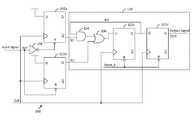
- FIG. 1illustrates a schematic diagram of a digital glitch filter in accordance with an embodiment of the present invention
- FIG. 2illustrates a timing diagram for the circuit of FIGS. 1 ;
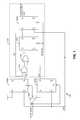
- FIG. 3illustrates a schematic diagram of a digital glitch filter in accordance with another embodiment of the present invention.
- a digital glitch filterfor filtering glitches in an input signal.
- the digital glitch filterincludes a first flip-flop for generating a first intermediate signal, based on detection of a negative glitch in the input signal.
- the input signalis provided to either a set terminal or a reset terminal of the first flip-flop.
- the digital glitch filterfurther includes a second flip-flop for generating a second intermediate signal, based on detection of a positive glitch in the input signal.
- the inverted input signalis provided to either a set terminal or a reset terminal of the second flip-flop.
- a synchronizeris connected to the first and second flip-flops for generating a filtered output signal, based on the first and second intermediate signals.
- the synchronizerincludes an AND gate connected to either an output terminal or an inverted output terminal of the first flip-flop.
- An OR gateis connected to either an output terminal or an inverted output terminal of the second flip-flop and an output terminal of the AND gate.
- the synchronizerfurther includes third and fourth flip-flops.
- the third flip-flophas an input terminal connected to an output terminal of the OR gate and an output terminal connected to an input terminal of the AND gate and generates a third intermediate signal based on the first and second intermediate signals.
- the fourth flip-flophas a data input terminal connected to the output terminal of the third flip-flop and generates the filtered output signal based on the third intermediate signal.
- a digital glitch filterfor filtering glitches in an input signal.
- the digital glitch filterincludes a first latch for generating a first intermediate signal based on detection of a negative glitch in the input signal.
- the input signalis provided to either a set terminal or a reset terminal of the first latch.
- the digital glitch filterfurther includes a second latch for generating a second intermediate signal based on detection of a positive glitch in the input signal.
- An inverted input signalis provided to at least one of a set terminal and a reset terminal of the second latch.
- a synchronizerconnected to the first and second latches for generating a filtered output signal based on the first and second intermediate signals.
- the synchronizerincludes an AND gate connected to an inverted output terminal of the first latch and an OR gate connected to an output terminal of the second latch and an output terminal of the AND gate.
- the synchronizerfurther includes first and second flip-flops.
- the first flip-flophas a data input terminal connected to an output terminal of the OR gate and an output terminal connected to an input terminal of the AND gate and generates a third intermediate signal, based on the first and second intermediate signals.
- the second flip-flophas a data input terminal connected to the output terminal of the first flip-flop and generates the filtered output signal based on the third intermediate signal.
- Various embodiments of the present inventionprovide a digital glitch filter for filtering glitches in an input signal.
- the glitchescause the first and second flip-flops to toggle between transmitting and non-transmitting states.
- the togglingfilters the glitches by preventing a short duration high input signal from being transmitted to the output stage of the digital glitch filter.
- the high input levelis transmitted to the synchronizer.
- the synchronizersynchronizes the changed output level with the input clock signal to generate a filtered output signal.
- the digital glitch filterincludes a maximum of four D-type flip-flops which results in a simple physical implementation of the digital glitch filter and reduces costs.
- the width of the glitch to be filteredmay be selected by adjusting the frequency of the input clock signal or by using a counter, thus providing the flexibility of filtering glitches with different widths.
- the digital glitch filter 100includes a plurality of flip-flops including a first flip-flop 102 a , a second flip-flop 102 b , a third flip-flop 102 c , and a fourth flip-flop 102 d , an AND gate 104 , an OR gate 106 , and a NOT gate 108 .
- the AND gate 104 , the OR gate 106 , the third flip-flop 102 c , and the fourth flip-flop 102 dare collectively referred to as a synchronizer 110 .
- Input and inverted input signalsare provided to the respective reset terminals of the first and second flip-flops 102 a and 102 b .
- the input signalis a digital signal that may include positive and/or negative glitches.
- An input clock signalis provided to the respective clock input terminals of the first flip-flop 102 a , the second flip-flop 102 b , the third flip-flop 102 c , and the fourth flip-flop 102 d .
- the first flip-flop 102 a , the second flip-flop 102 b , the third flip-flop 102 c , and the fourth flip-flop 102 dare D-type flip-flops.
- the data input terminals of the first and second flip-flops 102 a and 102 bare provided “logic 1” as an input.
- the first and second flip-flops 102 a and 102 bgenerate a first intermediate signal (N 1 ) and a second intermediate signal (N 2 ), respectively.
- the first and second intermediate signalsare generated based on detection of a glitch in the input signal. Additionally, the first and second intermediate signals are generated based on the input clock signal.
- the input clock signalis generated externally by a crystal oscillator.
- the first and second intermediate signalsare obtained at the inverted output and output terminals of the first and second flip-flops 102 a and 102 b , respectively.
- the input signal and the inverted input signalare provided to the set terminals of the first and second flip-flops 102 a and 102 b , respectively.
- the first and second intermediate signalsare obtained at the output and inverted output terminals of the first and second flip-flops 102 a and 102 b , respectively.
- the data input terminals of the first and second flip-flops 102 a and 102 bare provided “logic 0” as an input.
- the first and second intermediate signalsare provided to the synchronizer 110 .
- the synchronizer 110includes the third and fourth flip-flops 102 c and 102 d , that are connected in series to form a shift register.
- the synchronizer 110further includes the AND gate 104 and the OR gate 106 .
- the output terminal of the AND gate 104is connected to the input terminal of the OR gate 106 and the output terminal of the OR gate 106 is connected to the input terminal of the third flip-flop 102 c .
- the synchronizer 110synchronizes the first and second intermediate signals with the input clock signal to generate a filtered output signal.
- the first intermediate signalis provided to the AND gate 104 .
- the input terminal of the AND gate 104is connected to the output terminal of the first flip-flop 102 a .
- the second intermediate signalis provided to the OR gate 106 .
- the input terminal of the OR gate 106is connected to the inverted output terminal of the second flip-flop 102 b.
- the input clock signalis provided to the clock input terminal of the third flip-flop 102 c .
- the third flip-flop 102 cgenerates a third intermediate signal based on the output of the OR gate 106 and the input clock signal.
- the output terminal of the third flip-flop 102 cis connected to the input terminal of the AND gate 104 , to provide the third intermediate signal to the AND gate 104 .
- the third intermediate signalis provided to the input terminal of the fourth flip-flop 102 d .
- the fourth flip-flop 102 dgenerates the filtered output signal based on the third intermediate signal and the input clock signal.
- the timing diagram 200includes waveforms corresponding to the input signal (INP), the input clock signal (CLK), the first intermediate signal (N 1 ), the second intermediate signal (N 2 ), the third intermediate signal (N 3 ), and the filtered output signal (OUT).
- the functioning of the digital glitch filter 100has been explained in conjunction with the timing diagram 200 in detail.
- the input signalswitches to a high state. This results in the first intermediate signal switching to a high state. It will be understood by a person skilled in the art that the switching of the input signal to a high state causes the first flip-flop 102 a to enter a ‘non-released state’ in which the input at the input terminal of the first flip-flop 102 a does not shift to the output terminal. Since an inverted input signal is provided to the reset terminal of the second flip-flop 102 b , the second flip-flop 102 b switches to a ‘released state’ in which the second flip-flop 102 b is able to transmit the data at the input terminal to the output terminal.
- logic 1is provided to the input terminals of the first and second flip-flops 102 a and 102 b throughout the operation of the digital glitch filter 100 .
- a rising edgeis obtained in input clock signal that results in the second intermediate signal switching to a high state. This in turn causes the output terminal of the OR gate 106 to switch to a high state, and the input terminal of the third flip-flop 102 c to switch to a high state.
- the digital glitch filter 100may be programmed to eliminate glitches that have a duration less than a predetermined number of cycles of the input clock signal. This may be achieved by adjusting the input clock frequency or by using a counter.
- the input signalswitches to a high state.
- a rising clock edgeis obtained in input clock signal that causes the second intermediate signal and the input terminal of the third flip-flop 102 c to switch to a high state.
- the input signal and the second intermediate signalswitch to a low state. Since the input signal stays high for less than a clock cycle of the input clock signal, the high input at the input terminal of the third flip-flop 102 c (refer to FIG. 1 ) is not transmitted to the output terminal. As a result, the states of third intermediate and filtered output signals remain unchanged and the positive glitch is filtered successfully.
- the input signalswitches to a high state.
- a rising edgeis obtained in the input clock signal that causes the second intermediate signal and the input at the input terminal of the third flip-flop 102 c to switch to a high state.
- a rising edgeis obtained in the input clock signal that allows the third flip-flop 102 c to transmit the high input at the input terminal to the output terminal.
- the third intermediate signalswitches to a high state. Since the input signal stays high for more than one clock cycle, the high input at the input terminal of the third flip-flop 102 c is transmitted to the output terminal and the high state of the input signal is transferred to the third intermediate signal. This also results in the input at the input terminal of the fourth flip-flop 102 d to switch to a high state.
- the input signalswitches to a low state and subsequently, the second intermediate signal switches to a low state. This further leads to the input at the input terminal of the third flip-flop 102 c to switch to a low state.
- a rising edgeis obtained in the input clock signal that causes the fourth flip-flop 102 d to transmit the high input at the input terminal to the output terminal, thereby resulting in the filtered output signal switching to a high state.
- the first intermediate signalswitches to a low state.
- a rising edgeis obtained in the input clock signal and causes the third intermediate signal to switch to a low state which in turn causes the input at the input terminal of the fourth flip-flop 102 d to switch to a low state.
- a rising edgeis obtained in the input clock signal that causes the fourth flip-flop 102 d to transmit the low input at the input terminal to the output terminal.
- the filtered output signalswitches to a low state.
- the present inventioneliminates glitches by tracking the duration of a high/low state of the input signal.
- a high state of the second intermediate signal sampled at a rising edge of the input clock signalimplies that the duration of the high state is greater than the duration of two successively occurring rising edges of the input clock signal. Therefore, the high state is transmitted to the output (at time t 11 ).
- a low state of the first intermediate signal sampled at a rising edge of the input clock signal(at time t 12 ) implies that the duration of the low state is greater than the duration of two successively occurring rising edges of the input clock signal. Therefore, the low state is transmitted to the output (at time t 13 ).
- the high state of the input signal from t 7 -t 10can pass to the output, and the low state of the input signal from t 11 -t 13 can pass to the output.
- the remaining high/low states of the input signalare treated as positive/negative glitches and are filtered from the output.
- the input signal and the inverted input signalare provided to the set terminals of the first and second flip-flops 102 a and 102 b , respectively.
- the first and second intermediate signalsare obtained at the output and inverted output terminals of the first and second flip-flops 102 a and 102 b , respectively.
- “logic 0”is provided to the input terminals of the first and second flip-flops 102 a and 102 b .
- the reset terminals of the third and fourth flip-flops 102 c and 102 dare provided with a “RESET_B” signal to maintain the flip-flops in a ‘released state’ in which case the input at the input terminals are transmitted to the output terminals at the rising edge of the input clock signal.
- FIG. 3shows a schematic diagram of a digital glitch filter 300 in accordance with another embodiment of the present invention.
- the digital glitch filter 300is similar to the digital glitch filter 100 described in FIG. 1 , except that the first and second flip-flops 102 a and 102 b are replaced by first and second S-R latches 302 a and 302 b , respectively and additionally includes a NOT gate 304 .
- the first S-R latch 302 aincludes first and second NOR gates 306 a and 306 b respectively.
- the second S-R latch 302 bincludes third and fourth NOR gates 306 c and 306 d respectively.
- the NOT gate 304is connected between the output terminal of the second NOR gate 306 b and the input terminal of the AND gate 104 .
- An input signal and an input clock signalare provided to the set and reset terminals of the first S-R latch 302 a respectively.
- the input signal and the input clock signalare provided to the reset and set terminals of the first S-R latch 302 a , respectively.
- an inverted input signal and the input clock signalare provided to the set and reset terminals of the second S-R latch 302 b , respectively.
- the inverted input signal and the input clock signalare provided to the reset and set terminals of the second S-R latch 302 b , respectively.
Landscapes
- Physics & Mathematics (AREA)
- Nonlinear Science (AREA)
- Manipulation Of Pulses (AREA)
Abstract
Description
Claims (19)
Applications Claiming Priority (3)
| Application Number | Priority Date | Filing Date | Title |
|---|---|---|---|
| CN201110230237 | 2011-08-12 | ||
| CN201110230237.5ACN102931944B (en) | 2011-08-12 | 2011-08-12 | Digital burr filter |
| CN201110230237.5 | 2011-08-12 |
Publications (2)
| Publication Number | Publication Date |
|---|---|
| US20130038359A1 US20130038359A1 (en) | 2013-02-14 |
| US8558579B2true US8558579B2 (en) | 2013-10-15 |
Family
ID=47646674
Family Applications (1)
| Application Number | Title | Priority Date | Filing Date |
|---|---|---|---|
| US13/540,634Expired - Fee RelatedUS8558579B2 (en) | 2011-08-12 | 2012-07-03 | Digital glitch filter |
Country Status (2)
| Country | Link |
|---|---|
| US (1) | US8558579B2 (en) |
| CN (1) | CN102931944B (en) |
Cited By (5)
| Publication number | Priority date | Publication date | Assignee | Title |
|---|---|---|---|---|
| US10574218B2 (en) | 2018-06-08 | 2020-02-25 | Nxp Usa, Inc. | Digital glitch filter |
| US10690721B2 (en)* | 2018-09-12 | 2020-06-23 | Stmicroelectronics Asia Pacific Pte Ltd | Adaptive glitch detector for system on a chip |
| US10715124B2 (en) | 2018-09-14 | 2020-07-14 | Nxp Usa, Inc. | Glitch-free clock generator and method for generating glitch-free clock signal |
| US11177799B2 (en)* | 2019-10-18 | 2021-11-16 | Stmicroelectronics International N.V. | Debounce circuit with noise immunity and glitch event tracking |
| CN115542021A (en)* | 2021-06-30 | 2022-12-30 | 脸萌有限公司 | Pulse signal width measuring apparatus, method, system, and medium |
Families Citing this family (13)
| Publication number | Priority date | Publication date | Assignee | Title |
|---|---|---|---|---|
| KR102119038B1 (en) | 2013-05-23 | 2020-06-04 | 삼성전자주식회사 | Apparatus and method for controlling transparent tunnel mode operation in communication system supporting wireless docking protocol |
| EP2814223B1 (en)* | 2013-05-23 | 2018-09-26 | Samsung Electronics Co., Ltd | Method and apparatus for directly connecting dockee device to peripheral device in a wireless docking network |
| JP6376913B2 (en)* | 2014-09-10 | 2018-08-22 | キヤノン株式会社 | Electronics |
| CN104901656B (en)* | 2015-06-19 | 2018-09-25 | 中国电子科技集团公司第二十四研究所 | The method and its device of digital filtering Key dithering |
| CN104953985B (en)* | 2015-06-24 | 2018-01-30 | 青岛鼎信通讯股份有限公司 | A kind of digital filter circuit being applied in Long line transmission system |
| CN105141286B (en)* | 2015-10-16 | 2018-08-03 | 成都默一科技有限公司 | Filter out the digital filter of one clock period pulse and burr |
| CN107562163B (en)* | 2017-08-28 | 2020-03-31 | 上海集成电路研发中心有限公司 | Digital logic circuit with stable reset control |
| KR102540232B1 (en)* | 2017-12-21 | 2023-06-02 | 삼성전자주식회사 | A digital measurment circuit and a memory system using the same |
| CN112688670B (en)* | 2019-10-18 | 2024-12-13 | 意法半导体国际有限公司 | Debounce circuit with noise immunity and glitch event tracking |
| US11323106B1 (en) | 2020-11-23 | 2022-05-03 | Texas Instruments Incorporated | Glitch filter system |
| US11171659B1 (en)* | 2021-01-05 | 2021-11-09 | Micron Technology, Inc. | Techniques for reliable clock speed change and associated circuits and methods |
| CN112702043B (en)* | 2021-03-24 | 2021-08-10 | 上海海栎创科技股份有限公司 | Bidirectional deburring circuit |
| CN116827330B (en)* | 2022-12-12 | 2024-03-12 | 南京微盟电子有限公司 | Strong anti-interference communication port circuit |
Citations (12)
| Publication number | Priority date | Publication date | Assignee | Title |
|---|---|---|---|---|
| US4353032A (en)* | 1980-06-02 | 1982-10-05 | Tektronix, Inc. | Glitch detector |
| US4775840A (en)* | 1985-12-25 | 1988-10-04 | Iwatsu Electric Co., Ltd. | Noise removing circuit |
| US4786823A (en)* | 1986-04-18 | 1988-11-22 | Fujitsu Limited | Noise pulse suppressing circuit in digital system |
| US5001374A (en) | 1989-09-08 | 1991-03-19 | Amp Incorporated | Digital filter for removing short duration noise |
| US6535057B2 (en) | 2000-05-29 | 2003-03-18 | Stmicroelectronics Ltd. | Programmable glitch filter |
| US6778111B1 (en) | 2003-09-02 | 2004-08-17 | Hewlett-Packard Development Company, L.P. | Multi-dimensional deglitch filter for high speed digital signals |
| US6975406B2 (en) | 2001-08-02 | 2005-12-13 | Zygo Corporation | Glitch filter for distance measuring interferometry |
| US7519135B2 (en) | 2001-08-15 | 2009-04-14 | Texas Instruments Incorporated | Direct radio frequency (RF) sampling with recursive filtering method |
| US7579894B2 (en)* | 2006-04-11 | 2009-08-25 | Wolfson Microelectronics Plc | Debounce circuit and method |
| US7719320B2 (en) | 2004-12-10 | 2010-05-18 | Stmicroelectronics S.R.L. | Method and circuit for filtering glitches |
| US7724025B2 (en) | 2004-06-08 | 2010-05-25 | Robert Masleid | Leakage efficient anti-glitch filter |
| US7973860B2 (en)* | 2006-03-16 | 2011-07-05 | Quanta Computer Inc. | Method and apparatus for adjusting contrast of image |
Family Cites Families (5)
| Publication number | Priority date | Publication date | Assignee | Title |
|---|---|---|---|---|
| CN100495917C (en)* | 2006-04-03 | 2009-06-03 | 凌阳科技股份有限公司 | A surge separation circuit |
| US7397292B1 (en)* | 2006-06-21 | 2008-07-08 | National Semiconductor Corporation | Digital input buffer with glitch suppression |
| US7391257B1 (en)* | 2007-01-31 | 2008-06-24 | Medtronic, Inc. | Chopper-stabilized instrumentation amplifier for impedance measurement |
| JP4620752B2 (en)* | 2008-04-16 | 2011-01-26 | 日本電波工業株式会社 | Crystal device for surface mounting |
| CN101826855B (en)* | 2010-05-12 | 2012-10-03 | 四川和芯微电子股份有限公司 | Signal regulation system having summing-delta regulator |
- 2011
- 2011-08-12CNCN201110230237.5Apatent/CN102931944B/ennot_activeExpired - Fee Related
- 2012
- 2012-07-03USUS13/540,634patent/US8558579B2/ennot_activeExpired - Fee Related
Patent Citations (12)
| Publication number | Priority date | Publication date | Assignee | Title |
|---|---|---|---|---|
| US4353032A (en)* | 1980-06-02 | 1982-10-05 | Tektronix, Inc. | Glitch detector |
| US4775840A (en)* | 1985-12-25 | 1988-10-04 | Iwatsu Electric Co., Ltd. | Noise removing circuit |
| US4786823A (en)* | 1986-04-18 | 1988-11-22 | Fujitsu Limited | Noise pulse suppressing circuit in digital system |
| US5001374A (en) | 1989-09-08 | 1991-03-19 | Amp Incorporated | Digital filter for removing short duration noise |
| US6535057B2 (en) | 2000-05-29 | 2003-03-18 | Stmicroelectronics Ltd. | Programmable glitch filter |
| US6975406B2 (en) | 2001-08-02 | 2005-12-13 | Zygo Corporation | Glitch filter for distance measuring interferometry |
| US7519135B2 (en) | 2001-08-15 | 2009-04-14 | Texas Instruments Incorporated | Direct radio frequency (RF) sampling with recursive filtering method |
| US6778111B1 (en) | 2003-09-02 | 2004-08-17 | Hewlett-Packard Development Company, L.P. | Multi-dimensional deglitch filter for high speed digital signals |
| US7724025B2 (en) | 2004-06-08 | 2010-05-25 | Robert Masleid | Leakage efficient anti-glitch filter |
| US7719320B2 (en) | 2004-12-10 | 2010-05-18 | Stmicroelectronics S.R.L. | Method and circuit for filtering glitches |
| US7973860B2 (en)* | 2006-03-16 | 2011-07-05 | Quanta Computer Inc. | Method and apparatus for adjusting contrast of image |
| US7579894B2 (en)* | 2006-04-11 | 2009-08-25 | Wolfson Microelectronics Plc | Debounce circuit and method |
Cited By (7)
| Publication number | Priority date | Publication date | Assignee | Title |
|---|---|---|---|---|
| US10574218B2 (en) | 2018-06-08 | 2020-02-25 | Nxp Usa, Inc. | Digital glitch filter |
| US10690721B2 (en)* | 2018-09-12 | 2020-06-23 | Stmicroelectronics Asia Pacific Pte Ltd | Adaptive glitch detector for system on a chip |
| US10715124B2 (en) | 2018-09-14 | 2020-07-14 | Nxp Usa, Inc. | Glitch-free clock generator and method for generating glitch-free clock signal |
| US11177799B2 (en)* | 2019-10-18 | 2021-11-16 | Stmicroelectronics International N.V. | Debounce circuit with noise immunity and glitch event tracking |
| CN115542021A (en)* | 2021-06-30 | 2022-12-30 | 脸萌有限公司 | Pulse signal width measuring apparatus, method, system, and medium |
| US20230003781A1 (en)* | 2021-06-30 | 2023-01-05 | Lemon Inc. | Apparatus, method, system and medium for measuring pulse signal width |
| US12174232B2 (en)* | 2021-06-30 | 2024-12-24 | Lemon Inc. | Apparatus, method, system and medium for measuring pulse signal width |
Also Published As
| Publication number | Publication date |
|---|---|
| CN102931944B (en) | 2016-09-07 |
| US20130038359A1 (en) | 2013-02-14 |
| CN102931944A (en) | 2013-02-13 |
Similar Documents
| Publication | Publication Date | Title |
|---|---|---|
| US8558579B2 (en) | Digital glitch filter | |
| KR101374916B1 (en) | Pulse counter with clock edge recovery | |
| US20130207702A1 (en) | Edge selection techniques for correcting clock duty cycle | |
| US9685953B1 (en) | Low latency asynchronous interface circuits | |
| US12164327B2 (en) | Glitch-free clock switching circuit with clock loss tolerance and operation method thereof and glitch-free clock switching device | |
| US9337817B2 (en) | Hold-time optimization circuit and receiver with the same | |
| CN103208980B (en) | A kind of window voltage comparison means | |
| US9360883B1 (en) | Clock multiplexer for generating glitch-free clock signal | |
| US6414540B2 (en) | Input filter stage for a data stream, and method for filtering a data stream | |
| US20110260766A1 (en) | Digital suppression of spikes on an i2c bus | |
| KR20080101495A (en) | Clock switching circuit | |
| US11073862B2 (en) | Synchronization circuit and cascaded synchronization circuit for converting asynchronous signal into synchronous signal | |
| US20200162064A1 (en) | Debounce circuit using d flip-flops | |
| US9608603B2 (en) | Sampling circuit | |
| CN107565951B (en) | Multi-state signal generating circuit | |
| US10014849B2 (en) | Clock detectors and methods of detecting clocks | |
| US7342425B1 (en) | Method and apparatus for a symmetrical odd-number clock divider | |
| US7400178B2 (en) | Data output clock selection circuit for quad-data rate interface | |
| US6456146B1 (en) | System and method for multiplexing clocking signals | |
| US20230168708A1 (en) | Synchronizer circuit | |
| US20150030117A1 (en) | Shift frequency divider circuit | |
| US20040095166A1 (en) | Clock switching circuit | |
| US10305625B2 (en) | Data recovery circuit | |
| US8890594B1 (en) | System for functional reset across multiple clock domains | |
| US20050264328A1 (en) | Reset circuitry for an integrated circuit |
Legal Events
| Date | Code | Title | Description |
|---|---|---|---|
| AS | Assignment | Owner name:FREESCALE SEMICONDUCTOR, INC., TEXAS Free format text:ASSIGNMENT OF ASSIGNORS INTEREST;ASSIGNOR:ZHANG, JINGLIN;REEL/FRAME:028480/0594 Effective date:20110805 | |
| AS | Assignment | Owner name:CITIBANK, N.A., AS NOTES COLLATERAL AGENT, NEW YOR Free format text:SUPPLEMENT TO IP SECURITY AGREEMENT;ASSIGNOR:FREESCALE SEMICONDUCTOR, INC.;REEL/FRAME:030256/0471 Effective date:20121031 Owner name:CITIBANK, N.A., AS NOTES COLLATERAL AGENT, NEW YOR Free format text:SUPPLEMENT TO IP SECURITY AGREEMENT;ASSIGNOR:FREESCALE SEMICONDUCTOR, INC.;REEL/FRAME:030256/0544 Effective date:20121031 Owner name:CITIBANK, N.A., AS NOTES COLLATERAL AGENT, NEW YOR Free format text:SUPPLEMENT TO IP SECURITY AGREEMENT;ASSIGNOR:FREESCALE SEMICONDUCTOR, INC.;REEL/FRAME:030256/0625 Effective date:20121031 | |
| AS | Assignment | Owner name:CITIBANK, N.A., AS NOTES COLLATERAL AGENT, NEW YORK Free format text:SECURITY AGREEMENT;ASSIGNOR:FREESCALE SEMICONDUCTOR, INC.;REEL/FRAME:030633/0424 Effective date:20130521 Owner name:CITIBANK, N.A., AS NOTES COLLATERAL AGENT, NEW YOR Free format text:SECURITY AGREEMENT;ASSIGNOR:FREESCALE SEMICONDUCTOR, INC.;REEL/FRAME:030633/0424 Effective date:20130521 | |
| STCF | Information on status: patent grant | Free format text:PATENTED CASE | |
| AS | Assignment | Owner name:CITIBANK, N.A., AS NOTES COLLATERAL AGENT, NEW YORK Free format text:SECURITY AGREEMENT;ASSIGNOR:FREESCALE SEMICONDUCTOR, INC.;REEL/FRAME:031591/0266 Effective date:20131101 Owner name:CITIBANK, N.A., AS NOTES COLLATERAL AGENT, NEW YOR Free format text:SECURITY AGREEMENT;ASSIGNOR:FREESCALE SEMICONDUCTOR, INC.;REEL/FRAME:031591/0266 Effective date:20131101 | |
| AS | Assignment | Owner name:FREESCALE SEMICONDUCTOR, INC., TEXAS Free format text:PATENT RELEASE;ASSIGNOR:CITIBANK, N.A., AS COLLATERAL AGENT;REEL/FRAME:037357/0652 Effective date:20151207 Owner name:FREESCALE SEMICONDUCTOR, INC., TEXAS Free format text:PATENT RELEASE;ASSIGNOR:CITIBANK, N.A., AS COLLATERAL AGENT;REEL/FRAME:037357/0614 Effective date:20151207 Owner name:FREESCALE SEMICONDUCTOR, INC., TEXAS Free format text:PATENT RELEASE;ASSIGNOR:CITIBANK, N.A., AS COLLATERAL AGENT;REEL/FRAME:037357/0633 Effective date:20151207 | |
| AS | Assignment | Owner name:MORGAN STANLEY SENIOR FUNDING, INC., MARYLAND Free format text:ASSIGNMENT AND ASSUMPTION OF SECURITY INTEREST IN PATENTS;ASSIGNOR:CITIBANK, N.A.;REEL/FRAME:037486/0517 Effective date:20151207 | |
| AS | Assignment | Owner name:MORGAN STANLEY SENIOR FUNDING, INC., MARYLAND Free format text:ASSIGNMENT AND ASSUMPTION OF SECURITY INTEREST IN PATENTS;ASSIGNOR:CITIBANK, N.A.;REEL/FRAME:037518/0292 Effective date:20151207 | |
| AS | Assignment | Owner name:MORGAN STANLEY SENIOR FUNDING, INC., MARYLAND Free format text:SECURITY AGREEMENT SUPPLEMENT;ASSIGNOR:NXP B.V.;REEL/FRAME:038017/0058 Effective date:20160218 | |
| AS | Assignment | Owner name:MORGAN STANLEY SENIOR FUNDING, INC., MARYLAND Free format text:SUPPLEMENT TO THE SECURITY AGREEMENT;ASSIGNOR:FREESCALE SEMICONDUCTOR, INC.;REEL/FRAME:039138/0001 Effective date:20160525 | |
| AS | Assignment | Owner name:MORGAN STANLEY SENIOR FUNDING, INC., MARYLAND Free format text:CORRECTIVE ASSIGNMENT TO CORRECT THE REMOVE APPLICATION 12092129 PREVIOUSLY RECORDED ON REEL 038017 FRAME 0058. ASSIGNOR(S) HEREBY CONFIRMS THE SECURITY AGREEMENT SUPPLEMENT;ASSIGNOR:NXP B.V.;REEL/FRAME:039361/0212 Effective date:20160218 | |
| AS | Assignment | Owner name:NXP, B.V., F/K/A FREESCALE SEMICONDUCTOR, INC., NETHERLANDS Free format text:RELEASE BY SECURED PARTY;ASSIGNOR:MORGAN STANLEY SENIOR FUNDING, INC.;REEL/FRAME:040925/0001 Effective date:20160912 Owner name:NXP, B.V., F/K/A FREESCALE SEMICONDUCTOR, INC., NE Free format text:RELEASE BY SECURED PARTY;ASSIGNOR:MORGAN STANLEY SENIOR FUNDING, INC.;REEL/FRAME:040925/0001 Effective date:20160912 | |
| AS | Assignment | Owner name:NXP B.V., NETHERLANDS Free format text:RELEASE BY SECURED PARTY;ASSIGNOR:MORGAN STANLEY SENIOR FUNDING, INC.;REEL/FRAME:040928/0001 Effective date:20160622 | |
| AS | Assignment | Owner name:NXP USA, INC., TEXAS Free format text:MERGER;ASSIGNOR:FREESCALE SEMICONDUCTOR, INC.;REEL/FRAME:041144/0363 Effective date:20161107 | |
| AS | Assignment | Owner name:MORGAN STANLEY SENIOR FUNDING, INC., MARYLAND Free format text:CORRECTIVE ASSIGNMENT TO CORRECT THE REMOVE PATENTS 8108266 AND 8062324 AND REPLACE THEM WITH 6108266 AND 8060324 PREVIOUSLY RECORDED ON REEL 037518 FRAME 0292. ASSIGNOR(S) HEREBY CONFIRMS THE ASSIGNMENT AND ASSUMPTION OF SECURITY INTEREST IN PATENTS;ASSIGNOR:CITIBANK, N.A.;REEL/FRAME:041703/0536 Effective date:20151207 | |
| FPAY | Fee payment | Year of fee payment:4 | |
| AS | Assignment | Owner name:MORGAN STANLEY SENIOR FUNDING, INC., MARYLAND Free format text:CORRECTIVE ASSIGNMENT TO CORRECT THE REMOVE APPLICATION 12681366 PREVIOUSLY RECORDED ON REEL 039361 FRAME 0212. ASSIGNOR(S) HEREBY CONFIRMS THE SECURITY AGREEMENT SUPPLEMENT;ASSIGNOR:NXP B.V.;REEL/FRAME:042762/0145 Effective date:20160218 Owner name:MORGAN STANLEY SENIOR FUNDING, INC., MARYLAND Free format text:CORRECTIVE ASSIGNMENT TO CORRECT THE REMOVE APPLICATION 12681366 PREVIOUSLY RECORDED ON REEL 038017 FRAME 0058. ASSIGNOR(S) HEREBY CONFIRMS THE SECURITY AGREEMENT SUPPLEMENT;ASSIGNOR:NXP B.V.;REEL/FRAME:042985/0001 Effective date:20160218 | |
| AS | Assignment | Owner name:SHENZHEN XINGUODU TECHNOLOGY CO., LTD., CHINA Free format text:CORRECTIVE ASSIGNMENT TO CORRECT THE TO CORRECT THE APPLICATION NO. FROM 13,883,290 TO 13,833,290 PREVIOUSLY RECORDED ON REEL 041703 FRAME 0536. ASSIGNOR(S) HEREBY CONFIRMS THE THE ASSIGNMENT AND ASSUMPTION OF SECURITYINTEREST IN PATENTS.;ASSIGNOR:MORGAN STANLEY SENIOR FUNDING, INC.;REEL/FRAME:048734/0001 Effective date:20190217 | |
| AS | Assignment | Owner name:NXP B.V., NETHERLANDS Free format text:RELEASE BY SECURED PARTY;ASSIGNOR:MORGAN STANLEY SENIOR FUNDING, INC.;REEL/FRAME:050744/0097 Effective date:20190903 Owner name:NXP B.V., NETHERLANDS Free format text:RELEASE BY SECURED PARTY;ASSIGNOR:MORGAN STANLEY SENIOR FUNDING, INC.;REEL/FRAME:050745/0001 Effective date:20190903 | |
| AS | Assignment | Owner name:MORGAN STANLEY SENIOR FUNDING, INC., MARYLAND Free format text:CORRECTIVE ASSIGNMENT TO CORRECT THE REMOVE APPLICATION 12298143 PREVIOUSLY RECORDED ON REEL 042762 FRAME 0145. ASSIGNOR(S) HEREBY CONFIRMS THE SECURITY AGREEMENT SUPPLEMENT;ASSIGNOR:NXP B.V.;REEL/FRAME:051145/0184 Effective date:20160218 Owner name:MORGAN STANLEY SENIOR FUNDING, INC., MARYLAND Free format text:CORRECTIVE ASSIGNMENT TO CORRECT THE REMOVE APPLICATION 12298143 PREVIOUSLY RECORDED ON REEL 039361 FRAME 0212. ASSIGNOR(S) HEREBY CONFIRMS THE SECURITY AGREEMENT SUPPLEMENT;ASSIGNOR:NXP B.V.;REEL/FRAME:051029/0387 Effective date:20160218 Owner name:MORGAN STANLEY SENIOR FUNDING, INC., MARYLAND Free format text:CORRECTIVE ASSIGNMENT TO CORRECT THE REMOVE APPLICATION 12298143 PREVIOUSLY RECORDED ON REEL 042985 FRAME 0001. ASSIGNOR(S) HEREBY CONFIRMS THE SECURITY AGREEMENT SUPPLEMENT;ASSIGNOR:NXP B.V.;REEL/FRAME:051029/0001 Effective date:20160218 Owner name:MORGAN STANLEY SENIOR FUNDING, INC., MARYLAND Free format text:CORRECTIVE ASSIGNMENT TO CORRECT THE REMOVE APPLICATION 12298143 PREVIOUSLY RECORDED ON REEL 038017 FRAME 0058. ASSIGNOR(S) HEREBY CONFIRMS THE SECURITY AGREEMENT SUPPLEMENT;ASSIGNOR:NXP B.V.;REEL/FRAME:051030/0001 Effective date:20160218 Owner name:MORGAN STANLEY SENIOR FUNDING, INC., MARYLAND Free format text:CORRECTIVE ASSIGNMENT TO CORRECT THE REMOVE APPLICATION12298143 PREVIOUSLY RECORDED ON REEL 039361 FRAME 0212. ASSIGNOR(S) HEREBY CONFIRMS THE SECURITY AGREEMENT SUPPLEMENT;ASSIGNOR:NXP B.V.;REEL/FRAME:051029/0387 Effective date:20160218 Owner name:MORGAN STANLEY SENIOR FUNDING, INC., MARYLAND Free format text:CORRECTIVE ASSIGNMENT TO CORRECT THE REMOVE APPLICATION12298143 PREVIOUSLY RECORDED ON REEL 042985 FRAME 0001. ASSIGNOR(S) HEREBY CONFIRMS THE SECURITY AGREEMENT SUPPLEMENT;ASSIGNOR:NXP B.V.;REEL/FRAME:051029/0001 Effective date:20160218 Owner name:MORGAN STANLEY SENIOR FUNDING, INC., MARYLAND Free format text:CORRECTIVE ASSIGNMENT TO CORRECT THE REMOVE APPLICATION12298143 PREVIOUSLY RECORDED ON REEL 042762 FRAME 0145. ASSIGNOR(S) HEREBY CONFIRMS THE SECURITY AGREEMENT SUPPLEMENT;ASSIGNOR:NXP B.V.;REEL/FRAME:051145/0184 Effective date:20160218 | |
| AS | Assignment | Owner name:MORGAN STANLEY SENIOR FUNDING, INC., MARYLAND Free format text:CORRECTIVE ASSIGNMENT TO CORRECT THE REMOVE APPLICATION11759915 AND REPLACE IT WITH APPLICATION 11759935 PREVIOUSLY RECORDED ON REEL 037486 FRAME 0517. ASSIGNOR(S) HEREBY CONFIRMS THE ASSIGNMENT AND ASSUMPTION OF SECURITYINTEREST IN PATENTS;ASSIGNOR:CITIBANK, N.A.;REEL/FRAME:053547/0421 Effective date:20151207 | |
| AS | Assignment | Owner name:NXP B.V., NETHERLANDS Free format text:CORRECTIVE ASSIGNMENT TO CORRECT THE REMOVEAPPLICATION 11759915 AND REPLACE IT WITH APPLICATION11759935 PREVIOUSLY RECORDED ON REEL 040928 FRAME 0001. ASSIGNOR(S) HEREBY CONFIRMS THE RELEASE OF SECURITYINTEREST;ASSIGNOR:MORGAN STANLEY SENIOR FUNDING, INC.;REEL/FRAME:052915/0001 Effective date:20160622 | |
| AS | Assignment | Owner name:NXP, B.V. F/K/A FREESCALE SEMICONDUCTOR, INC., NETHERLANDS Free format text:CORRECTIVE ASSIGNMENT TO CORRECT THE REMOVEAPPLICATION 11759915 AND REPLACE IT WITH APPLICATION11759935 PREVIOUSLY RECORDED ON REEL 040925 FRAME 0001. ASSIGNOR(S) HEREBY CONFIRMS THE RELEASE OF SECURITYINTEREST;ASSIGNOR:MORGAN STANLEY SENIOR FUNDING, INC.;REEL/FRAME:052917/0001 Effective date:20160912 | |
| FEPP | Fee payment procedure | Free format text:MAINTENANCE FEE REMINDER MAILED (ORIGINAL EVENT CODE: REM.); ENTITY STATUS OF PATENT OWNER: LARGE ENTITY | |
| LAPS | Lapse for failure to pay maintenance fees | Free format text:PATENT EXPIRED FOR FAILURE TO PAY MAINTENANCE FEES (ORIGINAL EVENT CODE: EXP.); ENTITY STATUS OF PATENT OWNER: LARGE ENTITY | |
| STCH | Information on status: patent discontinuation | Free format text:PATENT EXPIRED DUE TO NONPAYMENT OF MAINTENANCE FEES UNDER 37 CFR 1.362 | |
| FP | Lapsed due to failure to pay maintenance fee | Effective date:20211015 |