US8558102B2 - Rotatable junction box for a solar module - Google Patents
Rotatable junction box for a solar moduleDownload PDFInfo
- Publication number
- US8558102B2 US8558102B2US12/558,336US55833609AUS8558102B2US 8558102 B2US8558102 B2US 8558102B2US 55833609 AUS55833609 AUS 55833609AUS 8558102 B2US8558102 B2US 8558102B2
- Authority
- US
- United States
- Prior art keywords
- insert
- junction box
- solar
- solar module
- module
- Prior art date
- Legal status (The legal status is an assumption and is not a legal conclusion. Google has not performed a legal analysis and makes no representation as to the accuracy of the status listed.)
- Active, expires
Links
Images


Classifications
- H—ELECTRICITY
- H02—GENERATION; CONVERSION OR DISTRIBUTION OF ELECTRIC POWER
- H02S—GENERATION OF ELECTRIC POWER BY CONVERSION OF INFRARED RADIATION, VISIBLE LIGHT OR ULTRAVIOLET LIGHT, e.g. USING PHOTOVOLTAIC [PV] MODULES
- H02S40/00—Components or accessories in combination with PV modules, not provided for in groups H02S10/00 - H02S30/00
- H02S40/30—Electrical components
- H02S40/34—Electrical components comprising specially adapted electrical connection means to be structurally associated with the PV module, e.g. junction boxes
- H—ELECTRICITY
- H02—GENERATION; CONVERSION OR DISTRIBUTION OF ELECTRIC POWER
- H02S—GENERATION OF ELECTRIC POWER BY CONVERSION OF INFRARED RADIATION, VISIBLE LIGHT OR ULTRAVIOLET LIGHT, e.g. USING PHOTOVOLTAIC [PV] MODULES
- H02S40/00—Components or accessories in combination with PV modules, not provided for in groups H02S10/00 - H02S30/00
- H02S40/30—Electrical components
- H02S40/32—Electrical components comprising DC/AC inverter means associated with the PV module itself, e.g. AC modules
- Y—GENERAL TAGGING OF NEW TECHNOLOGICAL DEVELOPMENTS; GENERAL TAGGING OF CROSS-SECTIONAL TECHNOLOGIES SPANNING OVER SEVERAL SECTIONS OF THE IPC; TECHNICAL SUBJECTS COVERED BY FORMER USPC CROSS-REFERENCE ART COLLECTIONS [XRACs] AND DIGESTS
- Y02—TECHNOLOGIES OR APPLICATIONS FOR MITIGATION OR ADAPTATION AGAINST CLIMATE CHANGE
- Y02E—REDUCTION OF GREENHOUSE GAS [GHG] EMISSIONS, RELATED TO ENERGY GENERATION, TRANSMISSION OR DISTRIBUTION
- Y02E10/00—Energy generation through renewable energy sources
- Y02E10/50—Photovoltaic [PV] energy
Definitions
- Photovoltaic cellsare widely used for generation of electricity, with multiple photovoltaic cells interconnected in module assemblies. Such modules may in turn be arranged in arrays and integrated into building structures or otherwise assembled to convert solar energy into electricity by the photovoltaic effect.
- a string of live modules connected in seriesis capable of delivering several amperes of current at lethal voltages, i.e., greater than 300 V.
- junction boxesfor solar modules.
- the junction boxes or J-boxescan be rotated or otherwise moved or changed to change the module's electrical connection state.
- the J-boxesare changeable between two or more orientations each associated with an electrical connection configuration.
- the configurationsinclude two or more of an on position, an off position, an on series configuration, an on series-parallel configuration, and a bypass configuration.
- a J-boxaccording to certain embodiments includes a fixed part and a separable part or insert.
- the insertmay include one or more bypass diodes, an inverter or a DC/DC converter.
- a detachable inverter or other componentincludes a fixed part and a separable part, i.e., an insert.
- the insertmay include one or more bypass diodes, inverters, DC/DC converters or combinations thereof.
- the insertmay or may not be movable between operating positions or orientations associated with different electrical connection configurations.
- junction boxfor a solar module assembly that includes a plurality of interconnected solar cells.
- the junction boxis mountable on or connectable to the solar module assembly and movable between at least two operating positions, with each operating position is associated with a different solar cell electrical connection configuration.
- the junction boxis movable by rotation.
- the junction boxmay include a housing and a movable insert.
- the insertis replaceable, so that it can be removed from the housing, rotated or otherwise moved to another orientation, and replaced into the housing in its new orientation.
- a replaceable insertgenerally refers to an insert that may be physically removed or detached from housing, and reinserted as desired. In certain cases, however, it may be desirable to replace the insert with a different insert. In other embodiments, the insert may be movable between operating positions without being physically removed from the housing.
- the housingmay contain external connection points, e.g., such as connectors attached to the housing directly or via cables housed within or attached to the housing.
- At least one solar cell electrical connection configurationmay be selected from a series configuration, a series-parallel configuration, an on position, an off position, and a bypass configuration.
- An insertmay include at least some of connectors, diodes and conductors configured such that moving the insert between two operating positions changes the solar cell electrical connection configuration.
- the junction boxmay contain an integral element such as DC/DC converter and/or an inverter. These may be located in the insert for easy replacement with new components.
- the insertmay be of any appropriate dimension or form to be inserted into, attached or otherwise configured to interface with a housing or other fixed portion.
- the detachable assembliesinclude a fixed part connectable to the solar module assembly and fixable with respect thereto, with the fixed part housing or containing an electrical pathway connectable to the plurality of interconnected solar cells; and a detachable insert housing or containing one or more circuitry components and configured to interface with the fixed part.
- the detachable insertinterfaces with the fixed part such that, in an operating position, the one or more circuitry components are electrically connected to the electrical pathway.
- the one or more circuitry componentsare unconnected to the electrical pathway.
- the detachable insertmay be removed from the module, e.g., for easy replacement of the insert or the components therein.
- Componentssuch as inverters, DC/DC converters, diodes, connectors, conductors and combinations thereof may be wholly or partially housed within the insert.
- the detachable insertmay be configured to interface with the fixed part in a single operating position, e.g., when inserted, the components in the insert are active, and when detached, the components in the insert are not active.
- the insertmay be movable between different operating positions.
- the insertmay be movable between at least two operating positions, each associated with a solar cell electrical connection configuration, e.g., between off, on-series, etc., as described above.
- the insertmay include a tool interface feature configured to interface with a tool whereby the insert can be detached from the fixed part.
- the detachable insertincludes one or more circuitry components, wherein the insert is configured to interface with a fixed part containing an electrical pathway to the plurality of interconnected solar cells, such that in an operating position, the one or more circuitry components are electrically connected to the electrical pathway, and in a detached position, the one or more circuitry components are unconnected to the electrical pathway.
- the junction boxes, detachable assembly or inserts described hereinfurther includes a tool interface feature configured to interface with a tool whereby the junction box, assembly or insert can be detached and/or moved between alternative operating positions.
- the junction box, assembly or insertmay be movable, detachable and/or reattachable only with the use of a tool.
- Another aspect of the inventionrelates to a solar module assembly including a plurality of interconnected solar modules, each module having at least one solar cell string and at least one external connection mechanism for interconnecting the modules, wherein at least one external connection mechanism is movable between operation positions to change the electrical connection configuration of interconnected modules or connected cell strings within a module.
- Yet another aspect of the inventionrelates to a method of installing or servicing a solar module system including at least one solar module having a plurality of interconnected solar cells.
- the methodinvolves moving or rotating a junction box mounted on a solar module between a first operating position and a second operating position to thereby change the solar cell electrical connection configuration.
- rotating the junction boxinvolves using a tool to interface with a tool interface feature on the junction box.
- Yet another aspect of the inventionrelates to a method of installing or servicing a solar module system including at least one solar module having a plurality of interconnected solar cells.
- the methodincludes removing a detachable insert comprising one or more circuitry components from a fixed part connected to the at least one solar module; replacing the one more circuitry components; and reattaching the detachable insert including the replacement components.
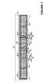
- FIG. 1shows a plan view of a solar-cell array including a plurality of solar-cell modules and centrally-mounted junction boxes in accordance with various embodiments.
- FIG. 2shows view of a junction box including removable insert mounted on a solar cell module. Views of the insert in removed and inserted positions are shown
- FIGS. 2A and 2Bdepicts a junction box including replaceable insert and junction box housing mounted on a solar module.
- FIG. 2Adepicts the insert in a removed (non-operating) position;
- FIG. 2Bdepicts the inserted in an operating position associated with an orientation of the insert.
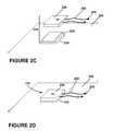
- FIGS. 2C and 2Ddepict another example of a junction box including replaceable insert and junction box housing mounted on a solar module.
- FIG. 2Cdepicts the insert in a removed (non-operating) position;
- FIG. 2Ddepicts the inserted in an operating position associated with an orientation of the insert.
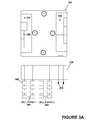
- FIG. 3Adepicts a rotatable insert and junction box housing connected to a solar module.
- the insertis in a non-operating position.
- FIG. 3Bdepicts the insert shown in FIG. 3A oriented such that the cells are wired in series/parallel.
- FIG. 3Cdepicts the insert shown in FIG. 3A oriented such that the module is off.
- FIG. 3Ddepicts the insert shown in FIG. 3A oriented such that the cells are wired in series.
- FIG. 3Edepicts the insert shown in FIG. 3A oriented such that the module is bypassed.
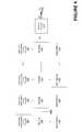
- FIG. 4is a diagram of solar modules, including detachable inserts each having a DC/DC converter, connected to a central inverter.
- FIG. 5is a diagram of solar modules including detachable inserts each having an inverter.
- FIG. 6depicts a detachable inverter connected to a solar module in a detached, non-operating position.
- FIG. 1is a plan view of a solar module array 102 including a plurality 110 of solar-cell modules 110 a , 110 b and 110 c and centrally-mounted junction boxes 130 a , 130 b and 130 c .
- Each moduleincludes a set of interconnected solar cells 140 .
- the cellsmay be any type of photovoltaic cells, including but not limited to CIS, CIGS, CdTe or silicon photovoltaic cells.
- the inventionis not limited to any particular arrangement of interconnected cells within the module, but may be used with any appropriate arrangement.
- the cells 140are connected in series, series/parallel, or in certain embodiments, switchable via the rotatable junction boxes described herein, between series and series/parallel configurations and other wiring configurations.
- the modulesmay also include one or more diodes connected to one or more photovoltaic cells of a photovoltaic module such that the diode will conduct electrical current if the cell(s) become damaged or shaded. For example, in the example shown in FIG.
- each moduleincludes a plurality of diodes, depicted as first, second and third diode assemblies 120 , 121 and 122 (shown only for solar-cell module 110 b ). As described further below, in certain embodiments, the modules described herein have only one bypass diode.
- Busbarsmay be used for current collection; in FIG. 1 , a first busbar 124 and a terminating busbar 126 are each electrically coupled with the first, second and third diode assemblies 120 , 121 and 122 .
- Busbars 128 and 129provide additional wiring to junction box 130 b to collect current.
- Each junction boxhas two cables or connectors attached to it, each configured to form an interconnector with another module.
- Interconnector 134connects centrally-mounted junction boxes 130 a and 130 b to connect solar modules 110 a and 110 b ; interconnector 138 connects centrally-mounted junction boxes 130 b and 130 c to interconnect solar-cell modules 110 b and 110 c .
- Junction box 130 bis attached to cable 134 b and cable 138 a .
- cable 134 aattached to junction box 130 a
- cable 134 bconnects module 110 b to module 110 a .
- cable 138 battached to module 110 c
- cable 138 aconnects module 110 b to module 110 c .
- Connectors joining the two cables of each interconnectare also shown.
- the modulesmay be connected in series, parallel, series-parallel, etc.
- the solar panel arraymay be mounted on a roof or other surface to absorb solar energy and convert it to electricity.
- DC currentis delivered from the modules via the junction boxes and to an inverter for conversion to AC.
- an inverteris included in the junction box to convert DC to AC at the module level.
- the modules and solar array described aboveis an example of solar module, junction box and array assemblies within the scope of the invention.
- the junction boxmay be placed as appropriate on the module—at its center, edge, etc.
- Cell wiring schemes, including the presence, absence, number or arrangement of busbars and diodesmay also be varied as appropriate.
- junction boxor “J-box” refers to a unit configured to contain or house an electrical pathway, typically between the cells or internal circuitry of a solar module and one or more external connectors.
- a junction box as described hereinmay a single, integral container or may include multiple parts or members.
- the junction boxes described hereininclude a fixed part and a movable and/or separable part.
- the junction boxes described hereininclude one or more of an external connection boxes housing one or more leads or connection points to other modules, e.g., with two such external connection boxes on a module.
- the electrical pathwaymay be interrupted, e.g., when the junction box is in an “off” position.
- the J-boxesare movable between orientations or operating positions to change an electrical connection configuration.
- the term “movable J-box”includes J-boxes in which the entire J-box is movable, as well as those that have a fixed part, such as a housing or base, and a movable part, also referred to herein as an insert.
- the fixed partis fixed or fixable with respect to the module, with the movable part movable with respect to the module and/or the fixed part.
- the fixed partmay be a housing or base mounted on or otherwise attached to the module, e.g., by adhesive sealing, mechanical attachment, magnetic force, etc.
- connection or pathway to the internal circuitry of the moduleis housed within the fixed part.
- the location of the fixed part relative to its respective photovoltaic moduleis not particularly restricted as long as the inverter is electrically connected to the module, i.e., it may be adjacent to the module and connected to it via busbars, etc.
- other componentsmay also be housed within or attached to the fixed portion, including but not limited to one or more conductors, diodes, and connectors.
- at least one conductoris housed within the movable part.
- the movable partmay also contain one or more connectors, diodes and conductors.
- the connectors, diodes and conductors in the fixed and/or movable partsare configured such that when the movable part is moved between operating positions, it interfaces with the fixed part to change an electrical connection configuration.
- the movable partis sometimes referred to as an “insert.”
- the term “insert”includes any part or member that is movable and/or separable from a fixed part, and configured to interface with the fixed part to provide an electrical connection.
- the J-boxesmay include multiple fixed parts and/or multiple movable parts.
- a fixed part and/or a movable partmay itself include multiple parts or members, all or a subset of which are configured to interface to provide an electrical connection.
- the inserts described hereinmay be reattached to the fixed parts by any appropriate method depending on their configurations, e.g., by inserting all or a portion of the insert into a recess, inserting all or a portion of the fixed part into a recess on the insert, placing the insert adjacent to the fixed part, etc.
- the insertis attached or reattached to the fixed part in an operating position, it is fixed with respect to the fixed part and module, until it is intentionally detached or moved.
- FIG. 2Adepicts a J-box 210 including replaceable insert 220 and J-box housing 230 mounted on a solar module 250 .
- Housing 230includes a recess 240 configured to accept insert 220 .
- J-box housing 230serves as the connection point to other modules, the grid, etc., via cables 260 having connectors 270 attached.
- the connectors 270may also be directly attached to or part of the housing 230 .
- Insert 220is in a particular orientation as indicated by the arrow, and may be rotated to different orientations. With the insert detached or removed as in FIG.
- FIG. 2Adepicts the J-box 210 once insert 220 is inserted into the housing 230 in the orientation indicated by the arrow. Inserted, the J-box 210 is in an operating position. In this orientation, the electrical connection is a particular configuration, e.g., on (current delivered to cables 260 ) or off (no current delivered to cables 260 ).
- FIG. 3Adepicts a J-box housing 330 and insert 320 for a solar module.
- Junction box housing 330is connected to cell strings 360 and 362 of the module.
- Connectors 370are attached to the housing 330 .
- Insert 320is movable between different positions, each of which is associated with a different electrical connection configuration. These positions are indicated as follows: 1: On parallel; 2: Off; 3: On series; and 4: Bypass.
- Insert 320contains connectors and conductors configured such that, depending on its orientation, it changes the way in which the strings of cells 360 and 362 are interconnected and/or the way the module is connected to other modules.
- bypass diodes 350are included in the insert 320 .
- bypass diodesare located within the module laminate, e.g., as depicted in FIG. 1 , and may be on a per-cell basis.
- FIGS. 3B-3Edepict insert 320 in each of its possible orientations as well as the associated electrical connection configuration of module and cell strings.
- insert 320is oriented such that cell string 360 and cell string 362 are wired in parallel.
- the electrical configuration of the cells 380 in FIG. 3Bmay also be referred to as series/parallel, with the cells in each string wired in series and the strings wired in parallel.
- Bypass diode 350is operable to prevent current from flowing back into cells that are not generating power due to shade, cell failure, etc. When the resistance due to a shaded cell or cells is greater than that of the bypass diode 350 , power is shunted through the diode.
- FIG. 3Cdepicts a DC-disconnect or off position.
- insert 330provides a hermetic seal to protect module and J-box components and for safety. Placing the insert in this operating position ensures that leads are not exposed to the environment at housing interface 375 .
- an insert having no conductors or other components but configured to fit into the J-box housingmay replace insert 330 , for example, where a module is being taken out of service for a lengthy period.
- insert 330is positioned such that cell strings 360 and 362 are wired in series.
- Bypass diodes 350are operable to bypass cell string 360 and/or 362 as needed.
- switching between parallel and series configurationse.g., by rotating insert 330 from position 1 to position 3
- a series configurationyields a higher voltage and lower current than a parallel configuration.
- Changing from one configuration to anotherinvolves removing, rotating and replacing insert 330 .
- FIGS. 3B and 3Ddepict parallel and series configurations, respectively, and FIG. 3C depicts an off position
- the J-boxmay have a single on position. This on position may compatible with cells strings wired in series and/or in parallel.
- FIGS. 3B and 3Ddepict parallel and series configurations, respectively, and FIG. 3C depicts an off position
- the J-boxmay have a single on position. This on position may compatible with cells strings wired in series and/or in parallel.
- FIGS. 3B and 3Ddepict parallel and series configurations, respectively, and
- FIG. 3Ea bypass configuration is depicted.
- currentflows via conductor 385 to and from the modules connected via connectors 370 .
- a modulecan be taken out of service while allowing other modules in the array to continue to supply power to a grid or battery.
- FIGS. 2C and 2Ddepict another embodiment in which a pluggable insert fits onto a base, with FIG. 2C showing the insert 220 in a detached position, and FIG. 2D showing the insert 220 in an operating position.
- insert 220is replaceable and has a recessed area (not shown) to fit onto raised portion 232 of housing or base 230 , which is fixed to module 250 .
- external connectors 270are attached via cables 260 to replaceable part 220 .
- the part 220may house only the leads to cables 260 (e.g., so the J-box is movable between two positions: on and off), or may include additional circuitry to be movable between other electrical connection states, e.g., on parallel, on series and/or bypass, instead of or in addition to these configurations.
- the insert 220is rotatable to interface with fixed part 230 in different orientations, each associated with a different operating position and electrical connection configuration. In other embodiments, described further below, the insert 220 is detachable but non-rotatable, i.e., there is a single operating position for the insert.
- J-boxes depicted in FIGS. 2A-2D and 3 A- 3 Emay be either in the fixed part (e.g., housing or base 230 in FIGS. 2A-2D ) or in the movable part (e.g., insert 220 in FIGS. 2A-2D ) of the J-box.
- the external connectorsmay be attached to either the fixed part of the J-box (as in FIGS. 2A and 2B ) or the movable part of the J-box (as in FIGS.
- per-module diodesmay be housed in the movable or fixed part.
- diodes and the likeare contained within the movable part for easy replacement.
- the movable partmay contain additional elements, including but not limited, to inverters, DC/DC converters and the like.
- elements such as diodes, inverters and the likeare included in a movable part for easy replacement of the element, and/or easy replacement with a different movable part, e.g., to change an electrical connection configuration.
- the J-box or insertis configured to change positions without being removed from module, housing or other fixed part.
- an insert or J-box containing conductors, etc.may be configured to be moved laterally from the housing, e.g., by sliding, to disconnect a circuit, and then rotated to change the part or J-box orientation and electrical connection configuration, without removing the insert from the housing or module.
- An insert or J-boxmay change positions by pivoting around a post, without being removed from the housing or module.
- the insert or J-boxmay be partially removable from the housing or module, e.g., it may be tethered by a wire or spring.
- the insertis detachable or separable from the fixed part of the J-box, without any physical connection to it.
- the shape of the movable insertmay also be varied, including rectangular-, circular-, triangular-shaped inserts, etc. Placement of each electrical connection configuration within the insert may also be varied as appropriate. For example, moving between series and parallel configurations may involve a 90° rotation, a 180° rotation, etc. Likewise moving between on and off configurations or any two configurations may involve a rotation of arbitrary degrees. Depending on the placement of configurations and the shape of the insert, the insert may be configured to move between positions by sliding, flipping, pressing, or other movements, either in addition to or instead of rotating the insert.
- the insertmay be snap fitted (i.e., held by tension), bolted, clamped, held by magnetic or other force, or fit by any other appropriate technique into, around, or next to the housing or base and may be inserted or otherwise attached and removed from the housing or base with relative ease.
- the term “insert”is broadly intended to cover any member, part or unit that is separable from and configured to interface with a housing, base or other fixed part of a J-box or other connection box on the module. This includes a part that fits within or is insertable into a recessed portion of a fixed part, a part that fits around a fixed part or a portion thereof, etc.
- the insert and housing or other fixed partare configured to interface with each other by complementary male/female members.
- the insertis movable and/or removable only with the aid of a tool.
- the toolmay be a commonly available tool, such as a screwdriver, or a specially configured tool.
- the insertincludes a feature configured to interface with the tool to move the insert between positions.
- the featuremay include a recess, e.g., to fit a screwdriver or uniquely shaped tool, a latch, a button, or other feature that requires a tool to interface with it.
- the J-boxes described hereinare generally movable between at least two operating positions associated with different electrical connection configurations. Possible operating configurations include on, off, on-series, on-parallel, and bypass. While FIGS. 3A-3E depict two cell strings, one of skill in the art will understand how to implement the J-boxes described herein with any number of cell strings in a module, e.g., one string, two strings, three strings, four strings or more. Similarly, the number of cells on a string may vary as appropriate for the particular module. Also, a solar module assembly may include a single solar module or any number of modules and interconnection schemes.
- the J-boxes described hereinmay include easily replaceable diodes.
- the diodesare part of the circuitry in the insert, as depicted above in FIGS. 3A-3E . With inserts that are removable or otherwise accessible (e.g., by flipping the insert to exposed the diodes), the diodes may be easily replaced.
- FIG. 4is a basic block diagram illustrating an array of solar modules 410 connected in series.
- solar modulesare interconnected via housings 420 , with a housing 420 mounted on or otherwise connected to or attached to each solar module 410 .
- the housing 420is integral to the encapsulation or other housing of solar module 410 .
- the housingmay be a junction box housing or other external connection.
- a detachable insert 430 including DC/DC converteris connected to each module 410 , in this example, via housing 420 . Input of the DC/DC converter is the DC generated by the associated solar module 410 .
- the DC/DC converterconverts the input DC to the voltage level required by central inverter 440 .
- the output DCis transmitted through housing 420 to central inverter 440 via conductor 425 .
- Using DC/DC convertersallows each module 410 to operate at its optimum current/voltage.
- the DC/DC convertermay operate in buck or boost mode as appropriate. In certain embodiments, it includes a buck converter connected to a boost converter. Once converted to AC by inverter 440 , the generated power may be transmitted to a grid or other AC electrical system.
- the insert 430is movable between operating positions as described above. So, for example, in one position the insert 430 may be associated with an off position (DC disconnect, no current to conductor 425 ), while in another position the insert 430 is associated with an on position including DC/DC conversion. On-series with DC/DC conversion, on-parallel with DC/DC conversion and bypass modes may also be supported as described above. As described further below, in certain embodiments, the insert is associated with only one operating position, but is detachable, e.g., for easy replacement of the insert or its components.
- the J-boxes described hereinmay also include an inverter configured to convert DC current from the module to AC for transmission to a grid.
- a J-boxmay contain a DC/AC inverter circuit.
- Arrays of solar panels having per-panel invertersare also provided. These may be advantageous as a central inverter, such as used in the system depicted in FIG. 4 , is not required.
- FIG. 5is a basic block diagram illustrating an array of solar modules 510 having per-module inverters. Solar modules 510 are connected in series via conductor 525 .
- conductor 525includes AC busbars to deliver AC to a grid or other AC electrical system.
- a detachable insert 540 including an inverteris connected to each module 510 , in this example, via housing 520 .
- Input of the inverteris the DC generated by the associated solar module 510 .
- the inverterconverts the input DC to AC, which is transmitted through housing 520 to a grid via conductor 525 .
- the insert 540is movable between operating positions as described above. So, for example, in one position the insert 540 may be associated with an off position (DC disconnect, no current to conductor 525 ), while in another position the insert 540 is associated with an on position including DC/AC conversion. On-series with DC/AC conversion, on-parallel with DC/AC conversion and bypass modes may also be supported as described above. It should be noted that although FIGS. 4 and 5 show the individual modules interconnected via the housings 520 , other connection schemes may be employed. For example, the modules may be connected via the detachable or movable inserts as depicted in FIGS. 2C and 2D .
- insertssuch as insert 430 and 540 are not rotatable or otherwise movable between operating positions, but are detachable, e.g., to disconnect a module or replace components within the insert, etc.
- replaceable insertsincluding any or all of diodes, DC/DC converters, inverters, or other solar module electrical components, to facilitate replacement of these components are provided.
- An inverterfor example, may have a useful life of no more than five years. To replace an inverter on a particular module, the insert is removed from the housing, e.g., using a tool. No longer electrically connected to the array or module, the inverter can be easily and safely replaced, and the insert containing the replacement inverter reinserted to the housing.
- the insert containing the inverter or other component(s)may also be movable between operating positions to change the electrical connection configuration of the cells or modules.
- the insertis not movable between operating positions, but is still configured to be detached and reattached as described above. In this manner, components contained in the insert may still be easily replaced.
- the housing without the insertis not active and its module is not electrically connected to the array.
- These replaceable insertsmay fit into junction box housing, as described above, or into other housing, base or fixed component, mounted on or in electrical contact with the module.
- detachable inserts or componentsthat include one or more circuitry elements, including but not limited to, one or more diodes, inverters or DC/DC converters, are provided. Certain embodiments of the detachable inverters, DC/DC converters, diodes, etc., are described above.
- a detachable inverterfor example, is an inverter that can be easily detached from its respective photovoltaic module, or if an inverter for an entire array or multiple modules, from its operating position.
- detachable insertscontaining one or more components for solar module or solar module array electrical connection are provided. Certain embodiments of the detachable inserts are described above. According to various embodiments, the detachable inserts are not movable between operating positions and are associated with only one electrical connection configuration when inserted. For example, referring to FIGS. 2A-2D , in certain embodiments, the insert 220 may be configured to be inserted into or plugged onto a housing 230 , in a single orientation, e.g., such that the module is on when inserted and off when not inserted. In other embodiments, the insert may be configured such that a single electrical connection configuration is associated with multiple orientations of the insert.
- the detachable insertsmay include any electrical component associated with a solar module or module array including but not limited to inverters, DC/DC converters, diodes, connectors and conductors.
- FIG. 6shows an example of an embodiment including inverter 610 , including insert or inverter element 620 , which may include a DC/AC inverter circuit, and an inverter housing 630 .
- the inverter housing 630is electrically connected via DC busbars 605 to the photovoltaic module 650 .
- the inverter housing 630also electrically contacts AC busbars 670 .
- the inverter 610is electrically connected to the module 650 via DC busbars 605 , which are integrated with the string.
- inverter 610While in this example inverter 610 is located adjacent to its respective photovoltaic module 650 , the location of the inverter 610 relative to its respective photovoltaic module 650 is not particularly restricted as long as the inverter is electrically connected to the module. According to other embodiments, the inverter housing may also be mounted on a module, e.g., as J-box housing 220 is in FIGS. 2A-2D .
- the inverter housing 630 without a detachable inverter element 620is not active, i.e. it can not convert DC of the photovoltaic module into AC.
- the insert 620is detachably located in the housing 630 .
- the insert 620may be of any appropriate shape or size, and may be snap fitted, bolted and/or clamped into the housing 630 and may be inserted and removed from the housing 630 with relative ease. Also as described above, in certain embodiments, the insert is removable only with the aid of a tool.
- the detachable insertsare not limited to housing inverter circuitry but may house DC/DC converter circuitry, diodes, etc. In complex designs, it may be useful to house part of the circuit in a fixed part and part of the circuit in an insert. Generally, the inverter, DC/DC converter, or other component is not active when the insert is detached or, if movable between operating positions, in an off position.
- the detachable inverters, DC/DC converters or other componentsare each associated with a solar module.
- a detachable inverter or other componentmay be associated with multiple modules or an entire array.
- the inserts described hereincan be advantageous for safe shipping of the system.
- the systemcan be shipped in an inactive state without the detachable inverter insert installed, and later activated by installing the detachable inverter inserts.
- Detachable inverter inserts or elementsare described in U.S. patent application Ser. No. 11/777,397 (published as U.S. Patent Publication No. 2009/0014058), incorporated by reference herein.
- a replaceable insert and housingin which connections between insert circuitry and housing circuitry are made via a connector structure including one or more male connectors on the insert and one or more corresponding finger-safe female connectors in the housing. Because the insert is not electrically connected once removed, the male connectors may be exposed during safe installation or replacement activities. Also as indicated above, once inserted, the insert may provide a hermetic seal. In certain embodiments, the insert may be movable between an on and off position, e.g., such that the insert provides a protective, hermetic seal when in an off position.
- an insert having no activate-able componentsmay be provided to provide a protective, hermetic seal during replacement, maintenance or other inactive periods.
Landscapes
- Photovoltaic Devices (AREA)
Abstract
Description
Claims (20)
Priority Applications (1)
| Application Number | Priority Date | Filing Date | Title |
|---|---|---|---|
| US12/558,336US8558102B2 (en) | 2009-09-11 | 2009-09-11 | Rotatable junction box for a solar module |
Applications Claiming Priority (1)
| Application Number | Priority Date | Filing Date | Title |
|---|---|---|---|
| US12/558,336US8558102B2 (en) | 2009-09-11 | 2009-09-11 | Rotatable junction box for a solar module |
Publications (2)
| Publication Number | Publication Date |
|---|---|
| US20110061705A1 US20110061705A1 (en) | 2011-03-17 |
| US8558102B2true US8558102B2 (en) | 2013-10-15 |
Family
ID=43729279
Family Applications (1)
| Application Number | Title | Priority Date | Filing Date |
|---|---|---|---|
| US12/558,336Active2032-08-10US8558102B2 (en) | 2009-09-11 | 2009-09-11 | Rotatable junction box for a solar module |
Country Status (1)
| Country | Link |
|---|---|
| US (1) | US8558102B2 (en) |
Cited By (7)
| Publication number | Priority date | Publication date | Assignee | Title |
|---|---|---|---|---|
| US20120007429A1 (en)* | 2010-07-09 | 2012-01-12 | Jochen Hantschel | Apparatus for providing an input DC voltage for a photovoltaic inverter and photovoltaic system including such apparatus |
| WO2015103298A1 (en)* | 2013-12-31 | 2015-07-09 | Marroquin Marco A | Alternating current photovoltaic module |
| US10008979B2 (en) | 2013-11-27 | 2018-06-26 | Sunpower Corporation | Integration of microinverter with photovoltaic module |
| US10097108B2 (en) | 2014-12-16 | 2018-10-09 | Abb Schweiz Ag | Energy panel arrangement power dissipation |
| US10348094B2 (en) | 2015-01-28 | 2019-07-09 | Abb Schweiz Ag | Energy panel arrangement shutdown |
| US10404060B2 (en) | 2015-02-22 | 2019-09-03 | Abb Schweiz Ag | Photovoltaic string reverse polarity detection |
| US11631947B2 (en) | 2020-03-26 | 2023-04-18 | Angelina Mincheva Galiteva | Fail proof electrical connector apparatus for solar photovoltaic modules |
Families Citing this family (75)
| Publication number | Priority date | Publication date | Assignee | Title |
|---|---|---|---|---|
| US10693415B2 (en) | 2007-12-05 | 2020-06-23 | Solaredge Technologies Ltd. | Testing of a photovoltaic panel |
| US11881814B2 (en) | 2005-12-05 | 2024-01-23 | Solaredge Technologies Ltd. | Testing of a photovoltaic panel |
| US8013472B2 (en) | 2006-12-06 | 2011-09-06 | Solaredge, Ltd. | Method for distributed power harvesting using DC power sources |
| US11687112B2 (en) | 2006-12-06 | 2023-06-27 | Solaredge Technologies Ltd. | Distributed power harvesting systems using DC power sources |
| US8384243B2 (en) | 2007-12-04 | 2013-02-26 | Solaredge Technologies Ltd. | Distributed power harvesting systems using DC power sources |
| US11296650B2 (en) | 2006-12-06 | 2022-04-05 | Solaredge Technologies Ltd. | System and method for protection during inverter shutdown in distributed power installations |
| US9088178B2 (en) | 2006-12-06 | 2015-07-21 | Solaredge Technologies Ltd | Distributed power harvesting systems using DC power sources |
| US8963369B2 (en) | 2007-12-04 | 2015-02-24 | Solaredge Technologies Ltd. | Distributed power harvesting systems using DC power sources |
| US11888387B2 (en) | 2006-12-06 | 2024-01-30 | Solaredge Technologies Ltd. | Safety mechanisms, wake up and shutdown methods in distributed power installations |
| US8473250B2 (en) | 2006-12-06 | 2013-06-25 | Solaredge, Ltd. | Monitoring of distributed power harvesting systems using DC power sources |
| US8319483B2 (en) | 2007-08-06 | 2012-11-27 | Solaredge Technologies Ltd. | Digital average input current control in power converter |
| US11569659B2 (en) | 2006-12-06 | 2023-01-31 | Solaredge Technologies Ltd. | Distributed power harvesting systems using DC power sources |
| US11309832B2 (en) | 2006-12-06 | 2022-04-19 | Solaredge Technologies Ltd. | Distributed power harvesting systems using DC power sources |
| US9130401B2 (en) | 2006-12-06 | 2015-09-08 | Solaredge Technologies Ltd. | Distributed power harvesting systems using DC power sources |
| US8947194B2 (en) | 2009-05-26 | 2015-02-03 | Solaredge Technologies Ltd. | Theft detection and prevention in a power generation system |
| US12316274B2 (en) | 2006-12-06 | 2025-05-27 | Solaredge Technologies Ltd. | Pairing of components in a direct current distributed power generation system |
| US9112379B2 (en) | 2006-12-06 | 2015-08-18 | Solaredge Technologies Ltd. | Pairing of components in a direct current distributed power generation system |
| US8319471B2 (en) | 2006-12-06 | 2012-11-27 | Solaredge, Ltd. | Battery power delivery module |
| US8816535B2 (en) | 2007-10-10 | 2014-08-26 | Solaredge Technologies, Ltd. | System and method for protection during inverter shutdown in distributed power installations |
| US11855231B2 (en) | 2006-12-06 | 2023-12-26 | Solaredge Technologies Ltd. | Distributed power harvesting systems using DC power sources |
| US11735910B2 (en) | 2006-12-06 | 2023-08-22 | Solaredge Technologies Ltd. | Distributed power system using direct current power sources |
| US8618692B2 (en) | 2007-12-04 | 2013-12-31 | Solaredge Technologies Ltd. | Distributed power system using direct current power sources |
| WO2009072076A2 (en) | 2007-12-05 | 2009-06-11 | Solaredge Technologies Ltd. | Current sensing on a mosfet |
| CN105244905B (en) | 2007-12-05 | 2019-05-21 | 太阳能安吉有限公司 | Release mechanism in distributed power device is waken up and method for closing |
| US11264947B2 (en) | 2007-12-05 | 2022-03-01 | Solaredge Technologies Ltd. | Testing of a photovoltaic panel |
| US8111052B2 (en) | 2008-03-24 | 2012-02-07 | Solaredge Technologies Ltd. | Zero voltage switching |
| EP2294669B8 (en) | 2008-05-05 | 2016-12-07 | Solaredge Technologies Ltd. | Direct current power combiner |
| US8558102B2 (en) | 2009-09-11 | 2013-10-15 | Miasole | Rotatable junction box for a solar module |
| US12418177B2 (en) | 2009-10-24 | 2025-09-16 | Solaredge Technologies Ltd. | Distributed power system using direct current power sources |
| US8710699B2 (en) | 2009-12-01 | 2014-04-29 | Solaredge Technologies Ltd. | Dual use photovoltaic system |
| US8235749B2 (en)* | 2010-05-25 | 2012-08-07 | Tyco Electronics Corporation | Electrical connector for photovoltaic modules |
| US20120024337A1 (en)* | 2010-07-29 | 2012-02-02 | John Bellacicco | Apparatus facilitating wiring of multiple solar panels |
| US10673229B2 (en) | 2010-11-09 | 2020-06-02 | Solaredge Technologies Ltd. | Arc detection and prevention in a power generation system |
| US10230310B2 (en) | 2016-04-05 | 2019-03-12 | Solaredge Technologies Ltd | Safety switch for photovoltaic systems |
| US10673222B2 (en) | 2010-11-09 | 2020-06-02 | Solaredge Technologies Ltd. | Arc detection and prevention in a power generation system |
| GB2485527B (en) | 2010-11-09 | 2012-12-19 | Solaredge Technologies Ltd | Arc detection and prevention in a power generation system |
| GB2486408A (en) | 2010-12-09 | 2012-06-20 | Solaredge Technologies Ltd | Disconnection of a string carrying direct current |
| GB2483317B (en) | 2011-01-12 | 2012-08-22 | Solaredge Technologies Ltd | Serially connected inverters |
| DE102011009005B4 (en)* | 2011-01-14 | 2014-07-31 | Solon Se | Electrical junction box for a photovoltaic module |
| KR101820376B1 (en)* | 2011-04-26 | 2018-01-19 | 엘지전자 주식회사 | Photovoltaic module |
| ITMI20110917A1 (en)* | 2011-05-23 | 2012-11-24 | Compel Electronics S P A | JUNCTION BOX FOR PHOTOVOLTAIC PANELS |
| US8570005B2 (en) | 2011-09-12 | 2013-10-29 | Solaredge Technologies Ltd. | Direct current link circuit |
| GB2498365A (en) | 2012-01-11 | 2013-07-17 | Solaredge Technologies Ltd | Photovoltaic module |
| KR101954194B1 (en)* | 2012-07-16 | 2019-03-05 | 엘지전자 주식회사 | Power converting apparatus, and photovoltaic module |
| KR101954195B1 (en)* | 2012-07-16 | 2019-03-05 | 엘지전자 주식회사 | Power converting apparatus, and photovoltaic module |
| GB2498790A (en) | 2012-01-30 | 2013-07-31 | Solaredge Technologies Ltd | Maximising power in a photovoltaic distributed power system |
| US9853565B2 (en) | 2012-01-30 | 2017-12-26 | Solaredge Technologies Ltd. | Maximized power in a photovoltaic distributed power system |
| GB2498791A (en) | 2012-01-30 | 2013-07-31 | Solaredge Technologies Ltd | Photovoltaic panel circuitry |
| US8962998B2 (en) | 2012-02-08 | 2015-02-24 | Shoals Technologies Group, Llc | Solar panel junction box capable of integrating with a variety of accessory modules, and method of use |
| GB2499991A (en) | 2012-03-05 | 2013-09-11 | Solaredge Technologies Ltd | DC link circuit for photovoltaic array |
| US10115841B2 (en)* | 2012-06-04 | 2018-10-30 | Solaredge Technologies Ltd. | Integrated photovoltaic panel circuitry |
| DE102012105726A1 (en)* | 2012-06-28 | 2014-01-02 | Christian Kirschner | Solar module has contact element housing and plug-in contact element with plug contact surface, which form section with projection surface outside the top projection formed from solar module, in contact position |
| US9548619B2 (en) | 2013-03-14 | 2017-01-17 | Solaredge Technologies Ltd. | Method and apparatus for storing and depleting energy |
| US9941813B2 (en) | 2013-03-14 | 2018-04-10 | Solaredge Technologies Ltd. | High frequency multi-level inverter |
| EP3506370B1 (en) | 2013-03-15 | 2023-12-20 | Solaredge Technologies Ltd. | Bypass mechanism |
| US10833629B2 (en) | 2013-03-15 | 2020-11-10 | Technology Research, Llc | Interface for renewable energy system |
| GB2515837A (en) | 2013-07-05 | 2015-01-07 | Rec Solar Pte Ltd | Solar cell assembly |
| US9318974B2 (en) | 2014-03-26 | 2016-04-19 | Solaredge Technologies Ltd. | Multi-level inverter with flying capacitor topology |
| US11811360B2 (en)* | 2014-03-28 | 2023-11-07 | Maxeon Solar Pte. Ltd. | High voltage solar modules |
| US10686399B2 (en)* | 2015-03-06 | 2020-06-16 | Enphase Energy, Inc. | Apparatus for mounting a power conditioner to a photovoltaic module frame |
| AR107145A1 (en)* | 2015-12-18 | 2018-03-28 | Southwire Co Llc | CURRENT INVERSORS OF SOLAR CELLS INTEGRATED TO A CABLE |
| US10599113B2 (en) | 2016-03-03 | 2020-03-24 | Solaredge Technologies Ltd. | Apparatus and method for determining an order of power devices in power generation systems |
| CN107153212B (en) | 2016-03-03 | 2023-07-28 | 太阳能安吉科技有限公司 | Method for mapping a power generation facility |
| US11081608B2 (en) | 2016-03-03 | 2021-08-03 | Solaredge Technologies Ltd. | Apparatus and method for determining an order of power devices in power generation systems |
| US11177663B2 (en) | 2016-04-05 | 2021-11-16 | Solaredge Technologies Ltd. | Chain of power devices |
| US11018623B2 (en) | 2016-04-05 | 2021-05-25 | Solaredge Technologies Ltd. | Safety switch for photovoltaic systems |
| US12057807B2 (en) | 2016-04-05 | 2024-08-06 | Solaredge Technologies Ltd. | Chain of power devices |
| EP3535825A1 (en)* | 2016-11-07 | 2019-09-11 | Southwire Company, LLC | Dead band direct current converter |
| US11251621B1 (en) | 2017-08-03 | 2022-02-15 | Southwire Company, Llc | Solar power generation system |
| US11438988B1 (en) | 2017-08-11 | 2022-09-06 | Southwire Company, Llc | DC power management system |
| US20190221692A1 (en)* | 2018-01-12 | 2019-07-18 | Jiaxiong Wang | Flexible Transparent-Semitransparent Hybrid Solar Window Membrane Module |
| JP6661686B2 (en)* | 2018-03-16 | 2020-03-11 | 矢崎総業株式会社 | Electrical junction box |
| CN212436067U (en)* | 2020-06-02 | 2021-01-29 | 精进电动科技股份有限公司 | Inverter shell and connecting structure of inverter and junction box |
| JP2023090679A (en)* | 2021-12-17 | 2023-06-29 | ソーラーエッジ テクノロジーズ リミテッド | Arrangement of substring in photovoltaic module |
| CN116865666B (en)* | 2023-09-05 | 2023-11-17 | 江苏泽润新能科技股份有限公司 | Photovoltaic metal junction box |
Citations (39)
| Publication number | Priority date | Publication date | Assignee | Title |
|---|---|---|---|---|
| US1014718A (en) | 1910-03-08 | 1912-01-16 | Isaac Hardy Parsons | Electrical coupling. |
| US3260835A (en) | 1964-02-04 | 1966-07-12 | Frank J Soukey | Radiant heating system |
| US3575752A (en) | 1968-05-22 | 1971-04-20 | Hercules Inc | Nonwoven bonding method |
| US3575721A (en) | 1965-04-26 | 1971-04-20 | Textron Inc | Solar cell arrays and connectors |
| US4089576A (en) | 1976-12-20 | 1978-05-16 | General Electric Company | Insulated connection of photovoltaic devices |
| US4310211A (en) | 1979-12-26 | 1982-01-12 | Amp Incorporated | High current contact system for solar modules |
| US4460232A (en) | 1982-05-24 | 1984-07-17 | Amp, Incorporated | Junction box for solar modules |
| JPS614266A (en)* | 1984-06-18 | 1986-01-10 | Nec Corp | solar cell module |
| US5290366A (en) | 1990-03-08 | 1994-03-01 | Siemens Solar Gmh | Laminated solar module |
| US5951785A (en)* | 1996-01-29 | 1999-09-14 | Sanyo Electric Co., Ltd. | Photo-voltaic apparatus |
| US6039616A (en) | 1998-11-25 | 2000-03-21 | Antaya Technologies Corporation | Circular electrical connector |
| US6093884A (en) | 1997-11-06 | 2000-07-25 | Canon Kabushiki Kaisha | Solar cell module, solar cell array having the module, power generation apparatus using the array, and inspection method and construction method of the apparatus |
| US6337436B1 (en) | 1999-05-07 | 2002-01-08 | Webasto Vehicle Systems International Gmbh | Solar module for attachment to motor vehicles and a process for its manufacture |
| US20020004325A1 (en) | 1998-11-25 | 2002-01-10 | Antaya Technologies Corporation | Circular electrical connector |
| US20020014262A1 (en) | 2000-07-10 | 2002-02-07 | Masaaki Matsushita | Photovoltaic power generation systems and methods of controlling photovoltaic power generation systems |
| JP2002359389A (en) | 2001-05-31 | 2002-12-13 | Kitani Denki Kk | Terminal box for solar power generation module wiring |
| US20030013352A1 (en) | 2000-08-30 | 2003-01-16 | Antaya Technologies Corporation | Connector terminal with resilient contacts |
| US6649822B2 (en) | 2000-10-13 | 2003-11-18 | Sharp Kabushiki Kaisha | Structure and method for mounting solar battery modules |
| US20040018782A1 (en) | 2002-07-26 | 2004-01-29 | Antaya Technologies Corporation | Electrical terminal |
| JP2004253475A (en) | 2003-02-18 | 2004-09-09 | Sharp Corp | Solar cell module, method of manufacturing solar cell module, and heat source used in the method |
| JP2005057274A (en) | 2003-07-31 | 2005-03-03 | Harting Electric Gmbh & Co Kg | Connection device for solar cell current module |
| JP2005129773A (en) | 2003-10-24 | 2005-05-19 | Kyocera Corp | Solar cell module and wiring for connecting solar cell elements |
| JP2005244144A (en)* | 2004-01-27 | 2005-09-08 | Kyocera Corp | Solar cell module and solar power generation apparatus using the same |
| US20060121771A1 (en) | 2004-12-03 | 2006-06-08 | Antaya Technologies Corporation | Grounding connector |
| US20070287322A1 (en) | 2006-05-15 | 2007-12-13 | Antaya Technologies Corporation | Electrical connector assembly |
| US20080041434A1 (en) | 2006-08-18 | 2008-02-21 | Nanosolar, Inc. | Methods and devices for large-scale solar installations |
| US20080283118A1 (en)* | 2007-05-17 | 2008-11-20 | Larankelo, Inc. | Photovoltaic ac inverter mount and interconnect |
| US20080289682A1 (en) | 2007-02-27 | 2008-11-27 | Adriani Paul M | Structures for Low Cost, Reliable Solar Modules |
| US20090114262A1 (en) | 2006-08-18 | 2009-05-07 | Adriani Paul M | Methods and Devices for Large-Scale Solar Installations |
| US7530843B1 (en) | 2008-03-19 | 2009-05-12 | Yazaki North America, Inc. | Sealed electrical terminal |
| US20090149069A1 (en) | 2007-12-11 | 2009-06-11 | Lasen Development Llc | Electrical-connection device, particularly for photovoltaic-cell solar panels |
| US20100068924A1 (en) | 2008-09-12 | 2010-03-18 | Dragon Energy Pte. Ltd. | Electrical connection system |
| US7700878B2 (en) | 2006-08-31 | 2010-04-20 | Antaya Technologies Corporation | Buss bar strip |
| US20100263704A1 (en)* | 2009-04-16 | 2010-10-21 | Enphase Energy, Inc. | Apparatus for coupling power generated by a photovoltaic module to an output |
| US20100294339A1 (en) | 2007-07-17 | 2010-11-25 | Miasole | photovoltaic device with a luminescent down-shifting material |
| US20100326490A1 (en)* | 2008-01-09 | 2010-12-30 | Tagliareni Russell V | Photovoltaic panel with hot plug connector |
| US20110061705A1 (en) | 2009-09-11 | 2011-03-17 | Miasole | Rotatable junction box for a solar module |
| US7963802B2 (en) | 2009-06-30 | 2011-06-21 | Miasole | External electrical connectors for solar modules |
| US20110308562A1 (en) | 2010-06-22 | 2011-12-22 | Miasole | Photovoltaic module electrical connectors |
Family Cites Families (1)
| Publication number | Priority date | Publication date | Assignee | Title |
|---|---|---|---|---|
| US6075074A (en)* | 1996-07-19 | 2000-06-13 | Morton International, Inc. | Continuous processing of powder coating compositions |
- 2009
- 2009-09-11USUS12/558,336patent/US8558102B2/enactiveActive
Patent Citations (67)
| Publication number | Priority date | Publication date | Assignee | Title |
|---|---|---|---|---|
| US1014718A (en) | 1910-03-08 | 1912-01-16 | Isaac Hardy Parsons | Electrical coupling. |
| US3260835A (en) | 1964-02-04 | 1966-07-12 | Frank J Soukey | Radiant heating system |
| US3575721A (en) | 1965-04-26 | 1971-04-20 | Textron Inc | Solar cell arrays and connectors |
| US3575752A (en) | 1968-05-22 | 1971-04-20 | Hercules Inc | Nonwoven bonding method |
| US4089576A (en) | 1976-12-20 | 1978-05-16 | General Electric Company | Insulated connection of photovoltaic devices |
| US4310211A (en) | 1979-12-26 | 1982-01-12 | Amp Incorporated | High current contact system for solar modules |
| US4460232A (en) | 1982-05-24 | 1984-07-17 | Amp, Incorporated | Junction box for solar modules |
| JPS614266A (en)* | 1984-06-18 | 1986-01-10 | Nec Corp | solar cell module |
| US5290366A (en) | 1990-03-08 | 1994-03-01 | Siemens Solar Gmh | Laminated solar module |
| US5951785A (en)* | 1996-01-29 | 1999-09-14 | Sanyo Electric Co., Ltd. | Photo-voltaic apparatus |
| US6093884A (en) | 1997-11-06 | 2000-07-25 | Canon Kabushiki Kaisha | Solar cell module, solar cell array having the module, power generation apparatus using the array, and inspection method and construction method of the apparatus |
| US20080214064A1 (en) | 1998-11-25 | 2008-09-04 | Antaya Technologies Corporation | Circular electrical connector |
| US20030017756A1 (en) | 1998-11-25 | 2003-01-23 | Antaya Technologies Corporation | Circular electrical connector |
| US6945831B2 (en) | 1998-11-25 | 2005-09-20 | Antaya Technologies Corporation | Circular electrical connector |
| US20020004325A1 (en) | 1998-11-25 | 2002-01-10 | Antaya Technologies Corporation | Circular electrical connector |
| US6780071B2 (en) | 1998-11-25 | 2004-08-24 | Antaya Technologies Corporation | Circular electrical connector |
| US6475043B2 (en) | 1998-11-25 | 2002-11-05 | Antaya Technologies Corporation | Circular electrical connector |
| US20020187690A1 (en) | 1998-11-25 | 2002-12-12 | Antaya Technologies Corporation | Circular electrical connector |
| US7553204B2 (en) | 1998-11-25 | 2009-06-30 | Antaya Technologies Corporation | Circular electrical connector |
| US6039616A (en) | 1998-11-25 | 2000-03-21 | Antaya Technologies Corporation | Circular electrical connector |
| US20040248477A1 (en) | 1998-11-25 | 2004-12-09 | Antaya Technologies Corporation | Circular electrical connector |
| US7371083B2 (en) | 1998-11-25 | 2008-05-13 | Antaya Technologies Corporation | Circular electrical connector |
| US6599157B2 (en) | 1998-11-25 | 2003-07-29 | Antaya Technologies Corporation | Circular electrical connector |
| US6599156B2 (en) | 1998-11-25 | 2003-07-29 | Antaya Technologies Corporation | Circular electrical connector |
| US6249966B1 (en) | 1998-11-25 | 2001-06-26 | Antaya Technologies Corporation | Method of forming a circular electrical connector |
| US20030203666A1 (en) | 1998-11-25 | 2003-10-30 | Antaya Technologies Corporation | Circular electrical connector |
| US7226299B2 (en) | 1998-11-25 | 2007-06-05 | Antaya Technologies Corporation | Circular electrical connector |
| US7083481B2 (en) | 1998-11-25 | 2006-08-01 | Antaya Technologies Corporation | Circular electrical connector |
| US20050239348A1 (en) | 1998-11-25 | 2005-10-27 | Antaya Technologies Corporation | Circular electrical connector |
| US6337436B1 (en) | 1999-05-07 | 2002-01-08 | Webasto Vehicle Systems International Gmbh | Solar module for attachment to motor vehicles and a process for its manufacture |
| US20020014262A1 (en) | 2000-07-10 | 2002-02-07 | Masaaki Matsushita | Photovoltaic power generation systems and methods of controlling photovoltaic power generation systems |
| US6607409B2 (en) | 2000-08-30 | 2003-08-19 | Antaya Technologies Corporation | Connector terminal with resilient contacts |
| US20030013352A1 (en) | 2000-08-30 | 2003-01-16 | Antaya Technologies Corporation | Connector terminal with resilient contacts |
| US6520812B1 (en) | 2000-08-30 | 2003-02-18 | Antaya Technologies Corporation | Connector terminal with resilient contacts |
| US6676455B2 (en) | 2000-08-30 | 2004-01-13 | Antaya Technologies Corporation | Connector terminal with resilient contacts |
| US6649822B2 (en) | 2000-10-13 | 2003-11-18 | Sharp Kabushiki Kaisha | Structure and method for mounting solar battery modules |
| JP2002359389A (en) | 2001-05-31 | 2002-12-13 | Kitani Denki Kk | Terminal box for solar power generation module wiring |
| US6790104B2 (en) | 2002-07-26 | 2004-09-14 | Antaya Technologies Corporation | Electrical terminal |
| US20040018782A1 (en) | 2002-07-26 | 2004-01-29 | Antaya Technologies Corporation | Electrical terminal |
| US20040237302A1 (en) | 2002-07-26 | 2004-12-02 | Antaya Technologies Corporation | Electrical terminal |
| US7296347B2 (en) | 2002-07-26 | 2007-11-20 | Antaya Technologies Corporation | Method of forming an electrical terminal |
| JP2004253475A (en) | 2003-02-18 | 2004-09-09 | Sharp Corp | Solar cell module, method of manufacturing solar cell module, and heat source used in the method |
| JP2005057274A (en) | 2003-07-31 | 2005-03-03 | Harting Electric Gmbh & Co Kg | Connection device for solar cell current module |
| JP2005129773A (en) | 2003-10-24 | 2005-05-19 | Kyocera Corp | Solar cell module and wiring for connecting solar cell elements |
| JP2005244144A (en)* | 2004-01-27 | 2005-09-08 | Kyocera Corp | Solar cell module and solar power generation apparatus using the same |
| US20060121771A1 (en) | 2004-12-03 | 2006-06-08 | Antaya Technologies Corporation | Grounding connector |
| US7255589B2 (en) | 2004-12-03 | 2007-08-14 | Antaya Technologies Corporation | Grounding connector |
| US7438610B2 (en) | 2004-12-03 | 2008-10-21 | Antaya Technologies Corporation | Grounding connector |
| US7182625B2 (en) | 2004-12-03 | 2007-02-27 | Antaya Technologies Corporation | Grounding connector |
| US20070287322A1 (en) | 2006-05-15 | 2007-12-13 | Antaya Technologies Corporation | Electrical connector assembly |
| US7662001B2 (en) | 2006-05-15 | 2010-02-16 | Antaya Technologies Corporation | Electrical connector assembly |
| US20080041434A1 (en) | 2006-08-18 | 2008-02-21 | Nanosolar, Inc. | Methods and devices for large-scale solar installations |
| US20090114262A1 (en) | 2006-08-18 | 2009-05-07 | Adriani Paul M | Methods and Devices for Large-Scale Solar Installations |
| US20100154859A1 (en) | 2006-08-31 | 2010-06-24 | Antaya Technologies Corporation | Buss bar strip |
| US7700878B2 (en) | 2006-08-31 | 2010-04-20 | Antaya Technologies Corporation | Buss bar strip |
| US20080289682A1 (en) | 2007-02-27 | 2008-11-27 | Adriani Paul M | Structures for Low Cost, Reliable Solar Modules |
| US20080283118A1 (en)* | 2007-05-17 | 2008-11-20 | Larankelo, Inc. | Photovoltaic ac inverter mount and interconnect |
| US20100294339A1 (en) | 2007-07-17 | 2010-11-25 | Miasole | photovoltaic device with a luminescent down-shifting material |
| US20090149069A1 (en) | 2007-12-11 | 2009-06-11 | Lasen Development Llc | Electrical-connection device, particularly for photovoltaic-cell solar panels |
| US20100326490A1 (en)* | 2008-01-09 | 2010-12-30 | Tagliareni Russell V | Photovoltaic panel with hot plug connector |
| US7530843B1 (en) | 2008-03-19 | 2009-05-12 | Yazaki North America, Inc. | Sealed electrical terminal |
| US20100068924A1 (en) | 2008-09-12 | 2010-03-18 | Dragon Energy Pte. Ltd. | Electrical connection system |
| US20100263704A1 (en)* | 2009-04-16 | 2010-10-21 | Enphase Energy, Inc. | Apparatus for coupling power generated by a photovoltaic module to an output |
| US7963802B2 (en) | 2009-06-30 | 2011-06-21 | Miasole | External electrical connectors for solar modules |
| US20110277811A1 (en) | 2009-06-30 | 2011-11-17 | Miasole | External electrical connectors for solar modules |
| US20110061705A1 (en) | 2009-09-11 | 2011-03-17 | Miasole | Rotatable junction box for a solar module |
| US20110308562A1 (en) | 2010-06-22 | 2011-12-22 | Miasole | Photovoltaic module electrical connectors |
Non-Patent Citations (11)
| Title |
|---|
| Allowed Claims as of Apr. 1, 2011 (312 Amendment entered), for U.S. Appl. No. 12/684,278. |
| Allowed Claims as of Oct. 13, 2011, for U.S. Appl. No. 13/104,885. |
| Corneille, et al., "External Electrical Connectors for Solar Modules," U.S. Appl. No. 13/104,885, filed May 10, 2011. |
| Corneille, et al., "External Electrical Connectors for Solar Modules," U.S. Appl. No. 13/632,727, filed Jan. 31, 2012. |
| International Bureau of WIPO. International Preliminary Report on Patentability, for Application No. PCT/US2008/008513. |
| International Search Report and Written Opinion mailed Feb. 12, 2009, for Application No. PCT/US2008/008513. |
| International Search Report and Written Opinion mailed Jan. 21, 2011, for Application No. PCT/US2010/040426. |
| Notice of Allowance for U.S. Appl. No. 12/684,278, mailed Mar. 7, 2011. |
| Notice of Allowance for U.S. Appl. No. 13/104,885, mailed Oct. 13, 2011. |
| Shufflebotham Paul, "Photovoltaic Module Electrical Connectors," U.S. Appl. No. 12/820,408, filed Jun. 22, 2010. |
| U.S. Appl. No. 12/544,984, Office Action mailed Jan. 5, 2012. |
Cited By (9)
| Publication number | Priority date | Publication date | Assignee | Title |
|---|---|---|---|---|
| US20120007429A1 (en)* | 2010-07-09 | 2012-01-12 | Jochen Hantschel | Apparatus for providing an input DC voltage for a photovoltaic inverter and photovoltaic system including such apparatus |
| US8749092B2 (en)* | 2010-07-09 | 2014-06-10 | Refu Elektronik Gmbh | Apparatus for providing an input DC voltage for a photovoltaic inverter and photovoltaic system including such apparatus |
| US10008979B2 (en) | 2013-11-27 | 2018-06-26 | Sunpower Corporation | Integration of microinverter with photovoltaic module |
| US11108356B2 (en) | 2013-11-27 | 2021-08-31 | Enphase Energy, Inc. | Integration of microinverter with photovoltaic module |
| WO2015103298A1 (en)* | 2013-12-31 | 2015-07-09 | Marroquin Marco A | Alternating current photovoltaic module |
| US10097108B2 (en) | 2014-12-16 | 2018-10-09 | Abb Schweiz Ag | Energy panel arrangement power dissipation |
| US10348094B2 (en) | 2015-01-28 | 2019-07-09 | Abb Schweiz Ag | Energy panel arrangement shutdown |
| US10404060B2 (en) | 2015-02-22 | 2019-09-03 | Abb Schweiz Ag | Photovoltaic string reverse polarity detection |
| US11631947B2 (en) | 2020-03-26 | 2023-04-18 | Angelina Mincheva Galiteva | Fail proof electrical connector apparatus for solar photovoltaic modules |
Also Published As
| Publication number | Publication date |
|---|---|
| US20110061705A1 (en) | 2011-03-17 |
Similar Documents
| Publication | Publication Date | Title |
|---|---|---|
| US8558102B2 (en) | Rotatable junction box for a solar module | |
| US20100019580A1 (en) | Detachable inverter for a solar module | |
| AU2008254828B9 (en) | Photovoltaic AC inverter mount and interconnect | |
| US20190363671A1 (en) | Diode-included connector, photovoltaic laminate and photovoltaic assembly using same | |
| US8097980B2 (en) | Distributed solar power plant and a method of its connection to the existing power grid | |
| US10833629B2 (en) | Interface for renewable energy system | |
| WO2014152765A2 (en) | Interface for renewable energy system | |
| EP2311163A1 (en) | Photovoltaic dc/dc micro-converter | |
| JP2018518934A (en) | General purpose photovoltaic laminate | |
| US20150288329A1 (en) | Junction Box | |
| KR101505186B1 (en) | Photovoltaic module | |
| KR102237578B1 (en) | One-touch connector integral photovoltaics module assembly and installing method thereof | |
| JP4798956B2 (en) | Solar cell module and solar power generation apparatus using the same | |
| GB2564123A (en) | Multi-purpose off-grid PV module design | |
| US20190020306A1 (en) | Bypass mechanisms for energy generation systems | |
| JP2010239083A (en) | Solar power system | |
| JP4578127B2 (en) | Solar cell module and solar power generation apparatus using the same | |
| KR101470059B1 (en) | Solar cell module | |
| EP3723281B1 (en) | Power wiring device | |
| JPH1052076A (en) | Solar power system | |
| CN119999358A (en) | Photovoltaic power generation module | |
| US20130257154A1 (en) | System for distributing electrical power supplied from a solar panel array | |
| KR20240088483A (en) | PV(photovoltaic) module | |
| CN119999359A (en) | Photovoltaic power generation module | |
| KR20240088484A (en) | PV(photovoltaic) module |
Legal Events
| Date | Code | Title | Description |
|---|---|---|---|
| AS | Assignment | Owner name:MIASOLE, CALIFORNIA Free format text:ASSIGNMENT OF ASSIGNORS INTEREST;ASSIGNORS:CROFT, STEVEN;EVERSON, SHAWN;REEL/FRAME:023221/0978 Effective date:20090911 | |
| AS | Assignment | Owner name:PINNACLE VENTURES, L.L.C., CALIFORNIA Free format text:SECURITY AGREEMENT;ASSIGNOR:MIASOLE;REEL/FRAME:028863/0887 Effective date:20120828 | |
| AS | Assignment | Owner name:MIASOLE, CALIFORNIA Free format text:RELEASE BY SECURED PARTY;ASSIGNOR:PINNACLE VENTURES, L.L.C.;REEL/FRAME:029579/0494 Effective date:20130107 | |
| STCF | Information on status: patent grant | Free format text:PATENTED CASE | |
| AS | Assignment | Owner name:HANERGY HOLDING GROUP LTD, CHINA Free format text:CONFIRMATORY ASSIGNMENT OF PATENT RIGHTS;ASSIGNOR:MIASOLE;REEL/FRAME:032127/0428 Effective date:20140109 | |
| AS | Assignment | Owner name:APOLLO PRECISION (FUJIAN) LIMITED, CHINA Free format text:ASSIGNMENT OF ASSIGNORS INTEREST;ASSIGNOR:HANERGY HOLDING GROUP LTD.;REEL/FRAME:034857/0281 Effective date:20141111 | |
| AS | Assignment | Owner name:BEIJING APOLLO DING RONG SOLAR TECHNOLOGY CO., LTD Free format text:ASSIGNMENT OF ASSIGNORS INTEREST;ASSIGNOR:APOLLO PRECISION (FUJIAN) LIMITED;REEL/FRAME:037895/0779 Effective date:20160225 | |
| AS | Assignment | Owner name:BEIJING APOLLO DING RONG SOLAR TECHNOLOGY CO., LTD Free format text:CORRECTIVE ASSIGNMENT TO CORRECT THE INCORRECT APPL. NO. 14/525,282 PREVIOUSLY RECORDED AT REEL: 037895 FRAME: 0779. ASSIGNOR(S) HEREBY CONFIRMS THE ASSIGNMENT;ASSIGNOR:APOLLO PRECISION (FUJIAN) LIMITED;REEL/FRAME:038213/0238 Effective date:20160225 | |
| FPAY | Fee payment | Year of fee payment:4 | |
| SULP | Surcharge for late payment | ||
| FEPP | Fee payment procedure | Free format text:MAINTENANCE FEE REMINDER MAILED (ORIGINAL EVENT CODE: REM.); ENTITY STATUS OF PATENT OWNER: LARGE ENTITY | |
| FEPP | Fee payment procedure | Free format text:7.5 YR SURCHARGE - LATE PMT W/IN 6 MO, LARGE ENTITY (ORIGINAL EVENT CODE: M1555); ENTITY STATUS OF PATENT OWNER: LARGE ENTITY | |
| MAFP | Maintenance fee payment | Free format text:PAYMENT OF MAINTENANCE FEE, 8TH YEAR, LARGE ENTITY (ORIGINAL EVENT CODE: M1552); ENTITY STATUS OF PATENT OWNER: LARGE ENTITY Year of fee payment:8 | |
| FEPP | Fee payment procedure | Free format text:MAINTENANCE FEE REMINDER MAILED (ORIGINAL EVENT CODE: REM.); ENTITY STATUS OF PATENT OWNER: LARGE ENTITY |