US8557113B2 - Cart and installation for treating biological liquid - Google Patents
Cart and installation for treating biological liquidDownload PDFInfo
- Publication number
- US8557113B2 US8557113B2US12/592,901US59290109AUS8557113B2US 8557113 B2US8557113 B2US 8557113B2US 59290109 AUS59290109 AUS 59290109AUS 8557113 B2US8557113 B2US 8557113B2
- Authority
- US
- United States
- Prior art keywords
- cart
- pump
- installation
- filter
- container
- Prior art date
- Legal status (The legal status is an assumption and is not a legal conclusion. Google has not performed a legal analysis and makes no representation as to the accuracy of the status listed.)
- Active, expires
Links
Images


Classifications
- C—CHEMISTRY; METALLURGY
- C12—BIOCHEMISTRY; BEER; SPIRITS; WINE; VINEGAR; MICROBIOLOGY; ENZYMOLOGY; MUTATION OR GENETIC ENGINEERING
- C12M—APPARATUS FOR ENZYMOLOGY OR MICROBIOLOGY; APPARATUS FOR CULTURING MICROORGANISMS FOR PRODUCING BIOMASS, FOR GROWING CELLS OR FOR OBTAINING FERMENTATION OR METABOLIC PRODUCTS, i.e. BIOREACTORS OR FERMENTERS
- C12M47/00—Means for after-treatment of the produced biomass or of the fermentation or metabolic products, e.g. storage of biomass
- C12M47/02—Separating microorganisms from the culture medium; Concentration of biomass
- B—PERFORMING OPERATIONS; TRANSPORTING
- B01—PHYSICAL OR CHEMICAL PROCESSES OR APPARATUS IN GENERAL
- B01L—CHEMICAL OR PHYSICAL LABORATORY APPARATUS FOR GENERAL USE
- B01L1/00—Enclosures; Chambers
- B01L1/52—Transportable laboratories; Field kits
- C—CHEMISTRY; METALLURGY
- C12—BIOCHEMISTRY; BEER; SPIRITS; WINE; VINEGAR; MICROBIOLOGY; ENZYMOLOGY; MUTATION OR GENETIC ENGINEERING
- C12M—APPARATUS FOR ENZYMOLOGY OR MICROBIOLOGY; APPARATUS FOR CULTURING MICROORGANISMS FOR PRODUCING BIOMASS, FOR GROWING CELLS OR FOR OBTAINING FERMENTATION OR METABOLIC PRODUCTS, i.e. BIOREACTORS OR FERMENTERS
- C12M29/00—Means for introduction, extraction or recirculation of materials, e.g. pumps
- B—PERFORMING OPERATIONS; TRANSPORTING
- B01—PHYSICAL OR CHEMICAL PROCESSES OR APPARATUS IN GENERAL
- B01L—CHEMICAL OR PHYSICAL LABORATORY APPARATUS FOR GENERAL USE
- B01L2200/00—Solutions for specific problems relating to chemical or physical laboratory apparatus
- B01L2200/02—Adapting objects or devices to another
- B—PERFORMING OPERATIONS; TRANSPORTING
- B01—PHYSICAL OR CHEMICAL PROCESSES OR APPARATUS IN GENERAL
- B01L—CHEMICAL OR PHYSICAL LABORATORY APPARATUS FOR GENERAL USE
- B01L2200/00—Solutions for specific problems relating to chemical or physical laboratory apparatus
- B01L2200/08—Ergonomic or safety aspects of handling devices
- B—PERFORMING OPERATIONS; TRANSPORTING
- B01—PHYSICAL OR CHEMICAL PROCESSES OR APPARATUS IN GENERAL
- B01L—CHEMICAL OR PHYSICAL LABORATORY APPARATUS FOR GENERAL USE
- B01L2300/00—Additional constructional details
- B01L2300/06—Auxiliary integrated devices, integrated components
- B01L2300/0681—Filter
- B—PERFORMING OPERATIONS; TRANSPORTING
- B01—PHYSICAL OR CHEMICAL PROCESSES OR APPARATUS IN GENERAL
- B01L—CHEMICAL OR PHYSICAL LABORATORY APPARATUS FOR GENERAL USE
- B01L2400/00—Moving or stopping fluids
- B01L2400/04—Moving fluids with specific forces or mechanical means
- B01L2400/0475—Moving fluids with specific forces or mechanical means specific mechanical means and fluid pressure
- B01L2400/0481—Moving fluids with specific forces or mechanical means specific mechanical means and fluid pressure squeezing of channels or chambers
- Y—GENERAL TAGGING OF NEW TECHNOLOGICAL DEVELOPMENTS; GENERAL TAGGING OF CROSS-SECTIONAL TECHNOLOGIES SPANNING OVER SEVERAL SECTIONS OF THE IPC; TECHNICAL SUBJECTS COVERED BY FORMER USPC CROSS-REFERENCE ART COLLECTIONS [XRACs] AND DIGESTS
- Y10—TECHNICAL SUBJECTS COVERED BY FORMER USPC
- Y10T—TECHNICAL SUBJECTS COVERED BY FORMER US CLASSIFICATION
- Y10T137/00—Fluid handling
- Y10T137/4673—Plural tanks or compartments with parallel flow
- Y—GENERAL TAGGING OF NEW TECHNOLOGICAL DEVELOPMENTS; GENERAL TAGGING OF CROSS-SECTIONAL TECHNOLOGIES SPANNING OVER SEVERAL SECTIONS OF THE IPC; TECHNICAL SUBJECTS COVERED BY FORMER USPC CROSS-REFERENCE ART COLLECTIONS [XRACs] AND DIGESTS
- Y10—TECHNICAL SUBJECTS COVERED BY FORMER USPC
- Y10T—TECHNICAL SUBJECTS COVERED BY FORMER US CLASSIFICATION
- Y10T137/00—Fluid handling
- Y10T137/8593—Systems
- Y10T137/85978—With pump
- Y10T137/86131—Plural
- Y—GENERAL TAGGING OF NEW TECHNOLOGICAL DEVELOPMENTS; GENERAL TAGGING OF CROSS-SECTIONAL TECHNOLOGIES SPANNING OVER SEVERAL SECTIONS OF THE IPC; TECHNICAL SUBJECTS COVERED BY FORMER USPC CROSS-REFERENCE ART COLLECTIONS [XRACs] AND DIGESTS
- Y10—TECHNICAL SUBJECTS COVERED BY FORMER USPC
- Y10T—TECHNICAL SUBJECTS COVERED BY FORMER US CLASSIFICATION
- Y10T137/00—Fluid handling
- Y10T137/8593—Systems
- Y10T137/86187—Plural tanks or compartments connected for serial flow
Definitions
- the inventionrelates to installations for treating a biological liquid, in particular, but not exclusively, for purifying a biopharmaceutical liquid in order to obtain products such as monoclonal antibodies, vaccines or recombinant proteins.
- biopharmaceutical liquidsare in general obtained by culture in a bioreactor and that they must then be purified to achieve the required characteristics of purity, concentration, absence of viruses, etc.
- the purificationis carried out by a succession of treatments such as clarification, to eliminate the residues from the bioreactor culture, and viral filtration sometimes followed by diafiltration and concentration by tangential flow filtration (TFF).
- Other operationsexist concerning purification, such as chromatography and sterile filtration (to remove bacteria).
- the purification treatmentsare essentially carried out by filtering operations in a circuit leading to a container for collecting the treated liquid.
- a number of types of container containing liquidscan be connected to the inlet of the circuit, such as the source container that contains the product to be treated, but also containers containing a cleaning liquid such as sodium hydroxide (NaOH), a rinsing liquid such as pure water or a buffer liquid such as a saline solution.
- a cleaning liquidsuch as sodium hydroxide (NaOH)
- a rinsing liquidsuch as pure water or a buffer liquid such as a saline solution.
- various other containers for collecting cleaning, rinsing or buffer liquid, or for collecting residuescan be connected to the outlet of the circuit.
- liquid treatmentscan be carried out sequentially, the collecting container for the first treatment potentially becoming the source container for the next treatment, and so on until the last treatment is carried out.
- the inventionaims to provide an installation for treating a biological liquid that is particularly simple, convenient and effective.
- a cart for a biological liquid treatment installationcharacterized in that it comprises a first lateral face, a second lateral face by which it is adapted to be juxtaposed against another cart and a front face which meets the two said lateral faces;
- said cartfurther comprising:
- the feed containeris provided to be linked by flexible disposable pipes to said pumps and to other elements of said installation, at least one of said other elements (e.g. a filter) being provided to be disposed on said other cart.
- said other elementse.g. a filter
- the installation which the cart according to the invention enables to be obtainedis provided to comprise disposable elements, for the most part flexible (“FlexwareTM products”), among which are the feed container for liquid to treat, a collecting container for treated liquid, sections of circuit including the disposable pipes as well as a filter or filter elements; and permanent or reusable elements (“hardware”), arranged in part on the cart according to the invention.
- disposable elementsfor the most part flexible (“FlexwareTM products”), among which are the feed container for liquid to treat, a collecting container for treated liquid, sections of circuit including the disposable pipes as well as a filter or filter elements; and permanent or reusable elements (“hardware”), arranged in part on the cart according to the invention.
- the assembly of such an installationis made simply by equipping the hardware, including the cart according to the invention, with the disposable elements, which comprise the components adapted to cooperate with the pumps (e.g. certain disposable pipes if the pumps are of the peristaltic type) and the feed container adapted to be received in the tank.
- the pumpse.g. certain disposable pipes if the pumps are of the peristaltic type
- the feed containeradapted to be received in the tank.
- the arrangement of these permanent elements on the cartis also predetermined to be particularly convenient and efficient.
- the second pump and the tankare thus each offset relative to the reference element constituted by the first pump.
- That first pumpis dictated by that of the main elements of the installation (such as the filter or filters) with which it cooperates and which are disposed on the other cart (or on any other support such as a table able to be juxtaposed against the cart according to the invention).
- This arrangementensures, firstly, fast mounting (and disassembly) of the installation by facilitating the connections and by limiting pipe crossings.
- the relative positioning between the tank and the first pumpis provided in order for the flexible disposable pipe linking that pump to the feed container to be as short as possible while respecting a minimum radius of curvature in order to avoid any risk of pinching.
- the reduction in the length of the disposable pipesenables the volume of biological liquid present in the pipes to be reduced. This makes it possible for example to achieve a smaller final volume in the case in which a treatment is carried out in which flow occurs in a loop to which belong the feed container and a filter from which the filtrate is evacuated, since at the end of treatment the feed container is empty or nearly so and the liquid is essentially present in the pipes. This reduction in the final volume enables a higher level of concentration to be attained.
- the inventionis also directed to providing an installation for treating a biological liquid, comprising a cart as set forth above, designated first cart, a filter and a second cart, juxtaposed against said first cart, and of which the upper face supports said filter such that an outlet point of said first pump is situated substantially facing an inlet/outlet aperture of said filter.
- an outlet point of the first pumpis situated substantially facing the aperture of the filter enables optimization of the length of the disposable pipe linking that outlet point to that aperture.
- the support for that filter by the second cartmakes it possible to facilitate the mounting of the installation according to the invention.
- the operations to be carried out on the installationare particularly simple to implement because it is essentially a matter of scrapping the disposable elements with which the carts are equipped, the removal operations being just as simple to carry out as the mounting operations.
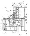
- FIG. 1is a diagrammatic view of a circuit of an installation for treatment by tangential filtration
- FIG. 2is a perspective view of a first and of a second cart according to the invention in separated configuration
- FIG. 3is a view from above of the installation according to the invention comprising the two carts of FIG. 2 in juxtaposed configuration;
- FIG. 4is a cross-section view of that installation on plane IV-IV of FIG. 3 ;
- FIG. 5is a cross-section view similar to that of FIG. 4 , but in which the tank is in lying-down position, its bottom being directed towards the second cart;
- FIG. 6is a cross-section view of that installation on plane VI-VI of FIG. 3 ;
- FIG. 7is a perspective view from another viewing angle of the two carts of FIG. 2 , in juxtaposed configuration.
- FIG. 8is a perspective view of a drawer of the second cart.
- FIG. 1of a circuit for treating a biological liquid by tangential filtration, produced using disposable elements installed on the two carts referred to above (the more detailed description of the installation will be given later).
- the liquid to be treatedis initially in a source bag 20 , filled with liquid from the culture bioreactor or from the previous treatment.
- This source bag 20is connectable via a male coupling connector 21 to a transfer section 22 which extends from a female coupling connector 28 to the first aperture 23 a of a T-shaped branching connector 23 .
- This transfer section 22comprises a disposable flexible pipe 24 , a transfer pump 25 to make the liquid flow (here a peristaltic pump operating in the same way in both flow directions) and two isolation valves 26 and 27 .
- pipemust be understood in the present document as being a portion of tubing connecting two elements of the circuit, it being possible for this portion equally well to comprise a unique tube or on the contrary several tubes, possibly having different diameters, connected in series by a simple connector (not playing any other role here) or sophisticated connector (for example a disposable connector for a pressure sensor (or for a sensor of another physico-chemical value) or a disposable pump head).
- Pipe 24has a portion 24 a passing right through pump 25 (from a first inlet/outlet point 25 a to a second inlet/outlet point 25 b ) such that it may be compressed by said pump.
- Valve 26is implanted on pipe 24 near the branching connector 23 in order to allow or prevent the flow of liquid in the pipe 24 .
- Valve 27is implanted on the pipe 24 close to the female coupling connector 28 .
- the operatorhas the possibility of connecting other bags 30 , 31 and 32 to the transfer section 22 , via male coupling connectors 33 , 34 and 35 which may connect to the female coupling connector 28 .
- These bags 30 , 31 and 32respectively contain a buffer liquid (saline solution), a cleaning liquid (sodium hydroxide) and a rinsing liquid (water) to manage the state of cleanliness of the circuit or to push the treated liquid towards the elements which perform the treatment or towards the collecting container.
- a buffer liquidsaline solution
- a cleaning liquidsodium hydroxide
- waterrinsing liquid
- a filling section 40 and a filtration section 41respectively extend from a second aperture 23 b and from a third aperture 23 c of the branching connector 23 .
- the filling section 40which joins to an inlet/outlet aperture 43 a of a flexible and disposable feed container 43 , comprises a flexible and disposable pipe 42 and a valve 44 implanted on the pipe 42 close to the branching connector 23 (also disposable).
- An agitator 44 actuated by an electromagnetic drive 45is disposed in the container 43 in order to make the liquid contained therein homogenous.
- the filtration section 41which joins to a first aperture 60 a of a T-shaped branching connector 60 , comprises two disposable flexible pipes 50 , 51 , two connectors 52 , 53 for pressure sensors, two isolation valves 54 , 55 and the tangential filter 58 .
- Pipe 50links the third aperture 23 c of branching connector 23 to a first inlet/outlet aperture 58 a of the filter 58 .
- Connector 52is inserted in series in pipe 50 .
- Pipe 51links a second inlet/outlet aperture 58 b of the filter 58 to the first aperture 60 a of branching connector 60 .
- Pressure sensor connector 53is inserted in series in pipe 51 .
- the measurement made by the pressure sensor mounted on connector 53in conjunction with the measurement made by the pressure sensor mounted on connector 52 , enables the operational state of the tangential filter 58 to be known.
- Valve 54is implanted on pipe 50 close to branching connector 23 , whereas valve 55 is implanted on pipe 51 close to branching connector 60 .
- a feed section 61 and a collecting section 62respectively extend from a second aperture 60 b and from a third aperture 60 c of the branching connector 60 .
- the feed section 61joins to an outlet aperture 43 b of the feed container 43 . It comprises a flexible and disposable pipe 63 , a flow pump 64 to make the liquid flow (here, a peristaltic pump operating in the same way in both flow directions), a valve 65 implanted on pipe 63 close to branching connector 60 , and a pressure sensor connector 66 inserted in series in pipe 63 .
- Pipe 63has a portion 63 a passing right through pump 64 (from an inlet point 64 a to an outlet point 64 b ) such that it may be compressed by said pump.
- the collecting section 62joins to a male coupling connector 70 . It solely comprises a flexible disposable pipe 68 and an isolation valve 69 implanted on pipe 68 close to branching connector 60 .
- the male coupling connector 70may be connected either to the female coupling connector 73 of a waste container 74 , or to the female coupling connector 71 of a collecting connector.
- the circuit for treatment by tangential filtrationalso comprises two sections 76 a , 76 b for conveying the filtrate which extend respectively from outlet points 58 c and 58 d of filter 58 and merge to form a single section 76 joining to a male coupling connector 86 which can be connected to the female coupling connector 73 of waste container 74 .
- Section 76 acommunicates with a first aperture 80 a of a T-shaped branching connector 80 . It comprises a flexible disposable pipe 77 and an isolation valve 78 implanted on pipe 77 close to filter 58 .
- Section 76 bcommunicates with a second aperture 80 b of the branching connector 80 . It comprises a flexible disposable pipe 81 , an isolating valve 82 implanted on pipe 81 close to filter 58 , and a pressure sensor connector 83 inserted in series in pipe 81 .
- Section 76which extends from a third aperture 80 c of the branching connector 80 , comprises a flexible disposable pipe 84 and a flowmeter 85 .
- Pipe 84has a portion 84 a passing right through the flowmeter 85 (from an inlet point 85 a to an outlet point 85 b ) such that the volume and the flow rate of the filtrate retrieved at the outlet of the filter 58 can be determined.
- Valves 54 , 65 and 69are closed in order to prevent any flow of liquid in the filtration section 41 and collecting section 62 , the other valves being open.
- the source bag 20is linked to section 22 by the connection of a male coupling connector 21 to the female coupling connector 28 .
- the liquid to treatis next sucked from the source bag 20 by the transfer pump 25 and is conveyed to the feed container 43 via the transfer section 22 and filling section 40 .
- the bag 30 containing the buffer liquidis connected via coupling connector 33 to coupling connector 28 .
- This buffer liquidis then introduced into transfer section 22 thanks to transfer pump 25 in order to push the liquid to treat towards section 40 such that the totality of that liquid can be filtered and retrieved.
- Transfer section 22is then isolated from the filling section 40 and filtration section 41 by closing valve 26 .
- valves 54 and 65are opened, the liquid to treat is made to flow by the actuation of flow pump 64 , in the sub-circuit formed by the feed section 61 , filtration section 41 and filling section 40 .
- the retentatecomes back to the feed container 43 whereas the filtrate is evacuated via sections 76 a , 76 b and 76 to be collected in the waste container 74 .
- the collection of the filtered liquidis then carried out in two successive sub-steps.
- the first sub-stepconsists of retrieving the filtered liquid contained in the filtration section 41 and in the filter 58 .
- valve 44is closed whereas valve 26 is opened so as to place the transfer 22 and filtration 41 sections in communication, and to isolate them from the filling section 40 .
- valve 65is closed whereas valve 69 is opened so as to place the filtration 41 and collecting 62 sections in communication, and to isolate them from the feed section 61 .
- the male coupling connector 70is connected to the female coupling connector 71 of the collecting container 72 .
- Buffer liquidis next conveyed in section 22 by virtue of transfer pump 25 in order to transfer the filtered liquid contained in the filtration section 41 and the filter 58 , via the collecting section 62 , to the collecting container 72 .
- the second sub-stepconsists of retrieving the filtered liquid contained in the filling 40 and feed 61 sections, and in the feed container 43 .
- valve 54is closed whereas valve 44 is opened so as to place the transfer 22 and filling 40 sections in communication, and to isolate them from the filtration section 41 .
- valve 55is closed whereas valve 65 is opened so as to place the feed 61 and collecting 62 sections in communication, and to isolate them from the filtration section 41 .
- Buffer liquidis then conveyed into section 22 by virtue of the transfer pump 25 in order to transfer the filtered liquid contained in the filling section 40 into the feed container 43 .
- the flow pump 64next enables that liquid to be brought from container 43 to collecting container 72 , via the feed 61 and collecting 62 sections.
- bag 31is placed in communication with transfer section 22 by connecting the male coupling connector 34 to the female coupling connector 28 .
- An intermediate female coupling connector (not shown in FIG. 1 for legibility) of section 22 situated between the transfer pump 25 and valve 26is temporarily connected to an intermediate male coupling connector (not illustrated) of section 61 situated between the feed container 43 and the flow pump 64 .
- An intermediate male coupling connector of section 22which is normally connected to the intermediate female coupling connector (not illustrated) is also temporarily connected to a second female coupling connector (not illustrated) of the waste container 74 , connector 73 being connected to male coupling connector 86 .
- the transfer pump 25is set to “open” position, such that all its rollers are away from portion 24 a of pipe 24 . Valves 44 and 69 are closed, the other valves being open.
- the cleaning liquidis then driven by the flow pump 64 in the circuit and then is retrieved in waste container 74 .
- the cleaning liquid having being evacuatedthe rinsing of the circuit is undertaken by connecting male coupling connector 35 of bag 32 to female coupling connector 28 .
- the rinsing liquidis then driven by the flow pump within the circuit, then retrieved in waste container 74 in the same way as described previously for the cleaning operations.
- a first rinseis carried out of the circuit prior to the cleaning by passage of sodium hydroxide and/or the sodium hydroxide is flushed by the passage of air before the final rinsing.
- This installation 1comprises two carts 2 and 3 each having a parallelepiped general shape and being of identical depth.
- first cart 2extends over a much greater height above the ground than that of the second cart 3 .
- the first cart 2is mounted on wheels 200 , and has two arcuate handles 200 a which project from a first lateral face 202 . It is hollow in order to receive certain elements of the circuit, and partly open at its front face 201 and at its lateral faces 202 and 203 in order to simplify the connection operations.
- Cart 2comprises ( FIG. 2 ):
- Tank 206comprises a cylindrical lateral wall 206 a of which one of the ends is extended by a frusto-conical bottom wall 206 b provided with an oblong opening 206 c ( FIG. 3 ) for the passage of the apertures 43 a and 43 b of the flexible and disposable feed container 43 , and two other circular openings 206 d and 206 e for the cooperation with the electromagnetic drive 45 and the temperature probe 211 .
- the tank 206is pivotally mounted on the lateral uprights 207 a of a U-shaped bracket 207 ( FIG. 2 ) situated in a plane parallel to the lateral faces 202 and 203 of the cart 2 and of which the ends are fixed to a weighing balance frame 208 resting on supports 209 linked to the chassis 204 .
- Load cells 210( FIG. 6 ) disposed between frame 208 and its supports 209 enable the mass of the tank 206 to be precisely determined.
- a handle 206 f ( FIG. 3 ) fixed to the free end of the cylindrical lateral wall 206 a of the tank 206enables it to be easily pivoted about an axis 212 perpendicular to the front face 201 , between an operating position ( FIG. 4 ) and an installation position ( FIG. 5 ).
- Two pins 213 ( FIG. 3 ) disposed on each of the uprights of the bracket 207 in the vicinity of axis 212are adapted to cooperate with two discs 214 fixed to the cylindrical lateral wall 206 a of the tank 206 to lock it in the desired position, or, on the contrary, to free it to rotate.
- the lockingis achieved by the insertion of a metal rod situated at the end of each pin 213 into a bore 214 a of the corresponding disc 214 . Conversely, to free the tank 206 to rotate, it suffices to pull on each of the pins 213 in order to make the rods come out of the discs 214 .
- the tank 206In its operating position, the tank 206 is upright, such that its frusto-conical bottom wall 206 b is turned towards the ground; the feed container 43 being disposed within the tank 206 , its apertures 43 a and 43 b projecting from that bottom wall 206 b towards the ground.
- this installation positionfacilitates the withdrawal of a spent feed container 43 and the installation of a new one.
- the temperature probe 211 and the electromagnetic drive 45 serving for the actuation of the magnetically driven agitator 44are fixed to a metal framework 217 ( FIGS. 4 and 5 ) pivotally mounted on the cross-member 207 b ( FIG. 2 ) forming the base of bracket 207 .
- the infrared temperature probe 211makes it possible to measure, through container 43 , the temperature change of the biological liquid during its treatment.
- the electromagnetic drive 45( FIG. 2 ) comprises several spools making it possible to raise and turn the agitator 44 contained in the feed container 43 .
- the framework 217is brought, using a handle 217 a , to its position illustrated in FIGS. 2 to 4 , in which the respective ends of the electromagnetic drive 45 and of the temperature probe 211 ( FIG. 2 ) are positioned as closely as possible to container 43 .
- a pin 219 ( FIG. 2 ) fixed to the cross member 207 bis adapted to cooperate with the framework 217 in order to lock it in that position throughout the duration of the filtration process.
- the framework 217is unlocked to freely pivot and to find its equilibrium position in which it rests on the chassis 204 of the cart 2 .
- the cart 3will now be described in more detail.
- cart 3is mounted on wheels 300 , and has arcuate handles 300 a which project from a first lateral face 305 ( FIG. 2 ).
- the upper face 303is entirely or partly formed by a plate of transparent material to enable the progress of the filling of the collecting container 72 to be followed.
- the tangential filter 58is disposed close to the first lateral face 305 and to the front face 307 , its four apertures 58 a , 58 b , 58 c and 58 d being oriented towards the second lateral face 308 of cart 3 .
- the four supports for the connectors 52 , 53 , 66 and 83are situated between the filter 58 and the second lateral face 308 .
- the storage drawers 304are slidingly mounted in the internal part of the cart 3 and are accessible from its first lateral face 305 which is open.
- a cut-out 306is provided in the facade of each drawer 304 in order to allow the passage of pipe 68 or 84 ( FIG. 8 ).
- the lateral face 203 of the first cart 2is juxtaposed against the lateral face 308 of the second cart 3 , as illustrated in FIGS. 3 to 7 .
- the carts 2 and 3lock to each other, here by virtue of the engagement of an lug (not visible in the drawings) in an accommodation 330 ( FIGS. 2 and 4 ) of cart 3 .
- the lug of cart 2is situated at the end of a plate 230 ( FIG. 4 ) fixed to the lower face of cart 2 .
- This lugprojects from face 203 and at its center has an opening where one or more retaining teeth come to locate, which are situated at one of the ends of a lever 331 ( FIG. 4 ) that is hinged on a pivot 332 carried by the lower face of cart 3 .
- the other end of lever 331is situated at lateral face 305 and comprises a pedal 333 ( FIG. 7 ) enabling the lever 331 to be tipped to release the teeth from the opening of the lug projecting from cart 2 , which enables the two carts to be freed.
- the disposable elementsare installed on the re-usable elements disposed on the carts 2 and 3 .
- the mounting of the installationis then terminated and the installation is in accordance with FIGS. 3 to 6 .
- FIG. 4which represents a cross-section of that complete installation with the pipes installed, enables it to be realized how the disposition of the two pumps 25 and 64 and of the tank 206 on cart 2 is optimized.
- the plate 221 which bears the flow pump 64is disposed in the vicinity of lateral face 203 of cart 2 at a predetermined height and depth (relative to the front face 201 ) such that the outlet point 64 b of the flow pump 64 is located substantially facing the inlet/outlet aperture 58 b of the tangential filter 58 ( FIG. 4 ).
- This positioningmakes it possible to limit the length of the pipes 63 and 51 between the flow pump 64 and the filter 58 , and thus the length of the sub-circuit in which the flow of the liquid occurs.
- the positioning of the tank 206 relative to the flow pump 64makes it possible to limit the length of pipe 63 between the feed container 43 and pump 64 , while taking into account the fact that this portion of pipe 63 has an elbow-shaped profile (since the outlet aperture 43 b of container 43 is vertically oriented towards the ground, whereas the inlet point 64 a of the flow pump 64 is horizontally oriented towards the tank 206 ).
- the radius of curvature of that elbowmust be equal to or greater than a minimum value Rmin which depends on the characteristics specific to that pipe.
- outlet aperture 43 b of container 43must be offset in terms of height and in terms of width relative to the inlet point 64 a of the flow pump 64 , by at least that value Rmin.
- the tank 206(receiving container 43 ) is positioned above and laterally displaced (in the direction of the lateral face 202 ) relative to pump 64 .
- this connector 23must be disposed, on mounting the circuit, in the vicinity of lateral face 203 of cart 2 , at a predetermined height and depth such that its aperture 23 c is situated substantially facing the inlet/outlet aperture 58 a of the tangential filter 58 ( FIG. 6 ).
- aperture 58 ais situated slightly higher and further forward than aperture 58 b .
- the aperture 23 c of branching connector 23( FIG. 6 ) must be positioned slightly higher and further forward than aperture 64 b of pump 64 .
- the vertical panel 223(on which is fixed branching connector 23 ) is positioned forward of pump 64 and at its upper portion ( FIGS. 2 , 6 and 7 ).
- Pump 25is thus offset towards the front relative to flow pump 64 such that it is disposed in the vicinity of the front face 201 of the cart ( FIGS. 2 and 3 ).
- the position of the transfer pump 25must also take into account the fact that the portion of pipe 24 between the transfer pump 25 and branching connector 23 has an elbow-shaped profile since the aperture 23 a of connector 23 is vertically oriented towards the ground whereas inlet/outlet point 25 b of transfer pump 25 is horizontally oriented ( FIG. 5 ).
- the radius of curvature of that elbowmust be equal to or greater than a minimum value R′min which depends on the characteristics specific to that pipe.
- the inlet/outlet point 25 b of transfer pump 25must be offset vertically and in width relative to the aperture 23 a of branching connector 23 , by at least that value R′min.
- transfer pump 25is positioned below branching connector 23 (and thus below pump 64 ) and it is laterally displaced towards lateral face 202 , which, furthermore, has the advantage of not increasing the width of the cart 2 which remains compact.
- carts 2 and 3may serve for carrying out different treatments than that of tangential filtration.
Landscapes
- Health & Medical Sciences (AREA)
- Chemical & Material Sciences (AREA)
- Life Sciences & Earth Sciences (AREA)
- Engineering & Computer Science (AREA)
- Organic Chemistry (AREA)
- Zoology (AREA)
- Bioinformatics & Cheminformatics (AREA)
- Wood Science & Technology (AREA)
- Biotechnology (AREA)
- Sustainable Development (AREA)
- Genetics & Genomics (AREA)
- Biomedical Technology (AREA)
- Microbiology (AREA)
- Biochemistry (AREA)
- General Engineering & Computer Science (AREA)
- General Health & Medical Sciences (AREA)
- Chemical Kinetics & Catalysis (AREA)
- Clinical Laboratory Science (AREA)
- External Artificial Organs (AREA)
- Apparatus Associated With Microorganisms And Enzymes (AREA)
- Medicines Containing Antibodies Or Antigens For Use As Internal Diagnostic Agents (AREA)
- Separation Using Semi-Permeable Membranes (AREA)
- Medicines That Contain Protein Lipid Enzymes And Other Medicines (AREA)
Abstract
Description
- a first pump;
- a second pump disposed below said first pump and laterally offset relative thereto towards said first lateral face; and
- a tank disposed above said first pump and offset laterally relative thereto towards said first lateral face, said tank being adapted to receive a feed container provided to contain said biological liquid.
- said second pump is offset depthwise relative to said first pump towards said front face;
- said tank is movably mounted between an upright service position for the operations of treating said biological liquid, and a lying-down installation position for the mounting or withdrawal of said feed container;
- said tank is adapted to pivot about an axis perpendicular to said front face of said cart;
- said cart comprises means for locking said tank in either of the positions of service and installation;
- said locking means comprise at least one pin;
- said tank is mounted on a U-shaped bracket of which the ends are fixed to a balance frame adapted to cooperate with load cells to determine the mass of said tank;
- said pumps are peristaltic pumps;
- said cart comprises an electromagnetic drive to raise and turn a stir bar contained in said feed container;
- said cart comprises a temperature probe for measuring, through said feed container, the temperature change of said biological liquid during said treatment; and/or said cart includes a control panel to control said pumps.
- said filter is a tangential filter;
- said installation comprises a container for collecting said filtered biological liquid, said collecting container being disposed in a housing of said second cart;
- said housing is formed by the interior of a drawer;
- the facade of said drawer comprises a cut-out through which a flexible disposable pipe passes;
- said installation comprises:
- a source container for said biological liquid;
- a feed container disposed in said tank of said cart;
- a container for collecting said filtered biological liquid;
- a transfer section for connecting said source container to a first aperture of a branching connector, comprising a member adapted to cooperate with said second pump of said cart to make said biological liquid flow;
- a filling section linking a second aperture of said branching connector to an inlet/outlet aperture of said feed container;
- a filtration section comprising said filter and connecting a third aperture of said branching connector to a first aperture of a second branching connector;
- a feed section linking a second aperture of said second branching connector to an inlet/outlet aperture of said feed container, and comprising a member adapted to cooperate with said first pump of said cart to make said biological liquid flow; and
- a section for collecting said filtered liquid to link a third aperture of said second branching connector to said collecting container;
- each of said transfer, filling, filtration, feed and collecting sections comprising at least one disposable pipe;
- said installation comprises at least one section for conveying the filtrate that serves to link an outlet point of said filter to a waste container, comprising at least one disposable pipe; and/or
- said installation comprises two said conveying sections extending from a respective said outlet point of said filter and joining together via a branching connector so as to form a single section.
- an
inner metal chassis 204 partly covered byflat panels 205; - a
feed tank 206 for receiving thefeed container 43; - the
electromagnetic drive 45; - the
transfer pump 25 andflow pump 64; - an infrared temperature probe211 (
FIG. 3 ) - two
horizontal trays pumps - a
vertical panel 223 bearing thevalves - the flowmeter85 (
FIG. 7 ) disposed in a recess of thelateral face 203 located abovepump 64; and - a
control panel 230 to control inparticular pumps panel 230 being disposed on thefront face 201 abovepump 64.
- an
- an inner metal chassis301 (
FIG. 4 ) partly covered byflat panels 302; - the supports for the
connectors connectors FIGS. 3 and 7 , they are disposable and are not permanently present on cart3); - the supports for
valves - two
parallel arms upper face 303 of thatcart 3, and on which rest thedisposable filter 58 and the supports for theconnectors - a
horizontal panel 317 extending from thearm 316 on which the supports forvalves - two storage drawers304 (
FIGS. 7 and 8 ) for storing the collecting72 and waste74 containers as well as any sampling or drainage containers, not illustrated for reasons of simplification.
- an inner metal chassis301 (
- rather than being horizontal,
plate 221, is inclined such that it drops towardsface 203, which is advantageous whensection 63aofpipe 63 is curved withinpump 64 such that its concavity is turned downwards (the rotor ofpump 64 turning about a horizontal axis): this enables pump64 to be inclined to avoid there being a low point inpipe 63 at inlet/outlet point 64a; section 22 is replaced by a similar section but comprising in addition a pressure sensor connector disposed between the second inlet/outlet point 25bofpump 25 andvalve 26 in order to ensure proper operation of thatpump 25;bags section 22, a set of valves positioned between those bags andsection 22 making it possible to select the liquid that it is desired to pass in the circuit;valve 65 is eliminated, the blocking function simply being obtained byflow pump 64 when stopped;- the
peristaltic pumps - when the volume of the
source bag 20 is greater than that of thefeed container 43, the operations for transfer of the liquid contained in that bag are carried out by the “fed batch” technique which consists of transferring only a part of the liquid from thesource bag 20 intofeed container 43, then of passing and concentrating that liquid in the sub-circuit formed bysections valve 26 remaining open) the rest of the liquid still contained inbag 20 which replaces the filtrate evacuated intowaste container 74; connector 53 is eliminated, the pressure sensor connected ontoconnector 66 then being used to provide similar information;- the
connectors - the
flowmeter 85 is replaced by a weighing balance on which the collectingcontainer 72 is placed in order to determine the mass and the rate of flow of the filtrate retrieved at the outlet offilter 58; - other measuring and verification instruments are installed, for example an electrical conductivity or pH measuring cell, or even a cell for measuring the absorbency of the liquid by ultraviolet;
drawers 304 are replaced by simple shelves which can be adjusted in height and on which roller mats and boxes are disposed in order to facilitate the positioning and withdrawal ofcontainers - when the collecting72 and waste74 containers are too voluminous to be introduced inside
cart 3, they are placed directly on the floor in the vicinity of thatcart 3; - the
male coupling connectors 70 and86 are linked to a drain; - the
metal framework 217 is replaced by a framework mounted so as to move vertically in translation relative to cross-member207b; - the
filter 58, theconnectors valves - a final filter is disposed between
valve 69 and the collectingcontainer 72.
- rather than being horizontal,
Claims (16)
Applications Claiming Priority (2)
| Application Number | Priority Date | Filing Date | Title |
|---|---|---|---|
| FR0859079AFR2940145B1 (en) | 2008-12-24 | 2008-12-24 | TROLLEY AND INSTALLATION FOR TREATING A BIOLOGICAL LIQUID |
| FR0859079 | 2008-12-24 |
Publications (2)
| Publication Number | Publication Date |
|---|---|
| US20100206785A1 US20100206785A1 (en) | 2010-08-19 |
| US8557113B2true US8557113B2 (en) | 2013-10-15 |
Family
ID=40888065
Family Applications (1)
| Application Number | Title | Priority Date | Filing Date |
|---|---|---|---|
| US12/592,901Active2031-07-25US8557113B2 (en) | 2008-12-24 | 2009-12-04 | Cart and installation for treating biological liquid |
Country Status (7)
| Country | Link |
|---|---|
| US (1) | US8557113B2 (en) |
| EP (1) | EP2208534B1 (en) |
| JP (1) | JP5342989B2 (en) |
| CN (1) | CN101758843B (en) |
| ES (1) | ES2463740T3 (en) |
| FR (1) | FR2940145B1 (en) |
| SG (1) | SG162672A1 (en) |
Cited By (10)
| Publication number | Priority date | Publication date | Assignee | Title |
|---|---|---|---|---|
| US20100187167A1 (en)* | 2009-01-23 | 2010-07-29 | Millipore Corporation | Method For Providing A Circuit For Biological Liquid And Circuit Obtained |
| US20120031510A1 (en)* | 2010-08-03 | 2012-02-09 | Millipore Corporation | Pump Cart For A Biological Liquid Treatment Installation |
| US8900454B2 (en) | 2010-06-08 | 2014-12-02 | Emd Millipore Corporation | Device for a biological liquid treatment installation |
| US8906229B2 (en) | 2010-06-08 | 2014-12-09 | Emd Millipore Corporation | Device for a biological liquid treatment installation |
| US8916045B2 (en) | 2011-03-28 | 2014-12-23 | Emd Millipore Corporation | Installation for treating a biological liquid |
| US9051929B2 (en) | 2010-01-13 | 2015-06-09 | Emd Millipore Corporation | Circuit for biological liquid |
| US9174171B2 (en) | 2010-06-23 | 2015-11-03 | Emd Millipore Corporation | Bag for a circuit of a biological liquid treatment installation |
| US9174145B2 (en) | 2010-06-23 | 2015-11-03 | Emd Millipore Corporation | Bag for a circuit of a biological liquid treatment installation |
| US9205955B2 (en) | 2010-06-08 | 2015-12-08 | Emd Millipore Corporation | Device for a biological liquid treatment installation |
| US9777847B2 (en) | 2012-07-23 | 2017-10-03 | Emd Millipore Corporation | Circuit for biological liquid comprising a pinch valve |
Families Citing this family (25)
| Publication number | Priority date | Publication date | Assignee | Title |
|---|---|---|---|---|
| FR2931838B1 (en) | 2008-06-02 | 2010-06-11 | Millipore Corp | INSTALLATION FOR TREATING A BIOLOGICAL LIQUID. |
| FR2940145B1 (en) | 2008-12-24 | 2011-03-25 | Millipore Corp | TROLLEY AND INSTALLATION FOR TREATING A BIOLOGICAL LIQUID |
| FR2958926B1 (en)* | 2010-04-14 | 2012-04-13 | Degremont | INSTALLATION FOR DESALINTING WATER, ESPECIALLY SEA WATER, AND CONNECTION FOR TUBE OF SUCH A INSTALLATION. |
| DE202010010362U1 (en)* | 2010-07-16 | 2010-10-21 | Wesemann Gmbh & Co. Kg | Apparatus for collecting liquid waste |
| EP4257159A3 (en) | 2012-10-24 | 2023-10-25 | Stryker Corporation | Mobile cart of a waste collection system |
| CN104933933A (en)* | 2015-06-09 | 2015-09-23 | 张宸岫 | Comprehensive chemical integration experiment device |
| EP3337598B1 (en)* | 2015-08-20 | 2024-01-03 | Cytiva Sweden AB | Re-circulation loop in cff/tff single use flow path |
| CN105151101B (en)* | 2015-09-22 | 2017-07-28 | 苏州韵蓝环保科技有限公司 | The installation rotating disk for the treatment of fluid storage box limits mechanism |
| CN105151092B (en)* | 2015-09-22 | 2017-07-25 | 苏州韵蓝环保科技有限公司 | A kind for the treatment of fluid storage box overturns transfer car(buggy) |
| WO2017160739A1 (en) | 2016-03-14 | 2017-09-21 | Pendo TECH | Processing system for multiple tangential flow filtration stations in bioprocessing applications |
| CN106607112B (en)* | 2016-12-06 | 2018-08-21 | 王淑彩 | A kind of automatic flushing draws water workbench |
| EP3381530A1 (en) | 2017-03-29 | 2018-10-03 | EMD Millipore Corporation | Facility for treating a biological fluid |
| EP3381529A1 (en)* | 2017-03-29 | 2018-10-03 | EMD Millipore Corporation | Facility for treating a biological fluid |
| LU100170B1 (en)* | 2017-04-13 | 2018-10-15 | Cytena Gmbh | Process for processing a liquid sample |
| EP3456399B1 (en) | 2017-09-19 | 2020-08-19 | Sartorius Stedim Biotech GmbH | Filter skid with tilting mechanism |
| US12152231B2 (en) | 2017-09-27 | 2024-11-26 | Univercells Technologies S.A. | System and method for the production of biomolecules such as viral vaccines |
| GB201717652D0 (en) | 2017-10-26 | 2017-12-13 | Ge Healthcare Bio Sciences Ab | Bioprocess System |
| WO2020020569A1 (en)* | 2018-07-27 | 2020-01-30 | Univercells S.A. | System and method for the production of biomolecules |
| US12364637B2 (en) | 2018-12-05 | 2025-07-22 | Stryker Corporation | Medical waste management system integrated within a medical facility |
| US20230340395A1 (en) | 2020-08-22 | 2023-10-26 | Merck Patent Gmbh | System for treating a biotechnological fluid |
| CN115916953A (en) | 2020-08-22 | 2023-04-04 | 默克专利股份公司 | System for processing biotechnological fluids |
| JP2023537432A (en) | 2020-08-22 | 2023-08-31 | メルク パテント ゲゼルシャフト ミット ベシュレンクテル ハフツング | System for processing biotechnological fluids |
| WO2022049093A1 (en)* | 2020-09-01 | 2022-03-10 | CureVac RNA Printer GmbH | Manufacturing device for a pharmaceutical product |
| CN113210028A (en)* | 2021-04-28 | 2021-08-06 | 高淑芳 | Pharmacy laboratory bench device |
| WO2023046605A1 (en) | 2021-09-22 | 2023-03-30 | Merck Patent Gmbh | Enhanced system for treating a biotechnological fluid using an adaptive software |
Citations (74)
| Publication number | Priority date | Publication date | Assignee | Title |
|---|---|---|---|---|
| US2413853A (en)* | 1942-03-18 | 1947-01-07 | Metalwash Machinery Co | Article washing machine |
| US3022229A (en) | 1957-04-01 | 1962-02-20 | Getinge Mek Verkst S Aktiebola | Cultivation plant |
| US3179117A (en)* | 1964-03-02 | 1965-04-20 | Cart Cleaning Corp Of America | Trailer mounted cleaner |
| US3667487A (en)* | 1970-12-11 | 1972-06-06 | Richardson Chem Cleaning Servi | Integrated chemical cleaning apparatus |
| FR2241615A1 (en) | 1973-08-22 | 1975-03-21 | Aseta | Tilting fermentation and homogenisation tank - for e.g. making improved wines, and allowing easy evacuation of marc |
| GB1434786A (en) | 1973-04-02 | 1976-05-05 | Lichtenstein E S | Apparatus including disposable array for processing body fluids |
| US4113623A (en) | 1977-04-25 | 1978-09-12 | Food Automation-Service Techniques, Inc. | Filter apparatus |
| US4332750A (en) | 1980-03-11 | 1982-06-01 | Essex Chemical Corporation | Blow-molding and degating hollow shapes |
| JPS6281543A (en) | 1985-10-07 | 1987-04-15 | Kyowa Seimitsu Kk | Apparatus for automatic pretreatment of specimen supplied to sampler in chromatograph apparatus |
| US4784751A (en)* | 1986-09-24 | 1988-11-15 | Keller Machine Works | Method and apparatus for reclaiming contaminated oil |
| US4852851A (en) | 1987-12-11 | 1989-08-01 | Integrated Fluidics, Inc. | Valve with flexible sheet member |
| US4855236A (en)* | 1983-07-26 | 1989-08-08 | P. B. Ind. Plant Biotech Industries Ltd. | Process for plant tissue culture propagation |
| US4915119A (en)* | 1986-04-21 | 1990-04-10 | Dober Chemical Corporation | Cleaning apparatus and method |
| EP0479047A2 (en) | 1990-10-02 | 1992-04-08 | Daiichi Kogyo Kabushiki Kaisha | Apparatus and method for evacuating blood aspiration tubes |
| US5141866A (en)* | 1983-07-26 | 1992-08-25 | Robert Levin | Process for plant tissue culture propagation |
| FR2673853A1 (en) | 1991-03-12 | 1992-09-18 | Leflond Odile | IMMERSION ROTATING MIXER REACTOR, IN PARTICULAR FOR THE ANAEROBIC FERMENTATION OF HUMIDIFIED HOUSEHOLD GARMENTS. |
| US5265912A (en)* | 1992-10-19 | 1993-11-30 | Natividad Jeffrey A | Toy train apparatus |
| US5290518A (en) | 1992-08-17 | 1994-03-01 | Eastman Kodak Company | Flexible extraction device with burstable sidewall |
| US5342463A (en) | 1991-10-28 | 1994-08-30 | Centro Sviluppo Settori Impiego S.R.L. | Process for producing shaped articles by starting from reinforced thermoplastic sheets |
| US5520885A (en) | 1993-01-19 | 1996-05-28 | Thermogenesis Corporation | Fibrinogen processing apparatus, method and container |
| EP0803723A1 (en) | 1996-04-22 | 1997-10-29 | Compagnie Generale Des Matieres Nucleaires | Device for taking noxious liquidsampler, in particular loaded with solid particulates |
| US5985653A (en)* | 1995-06-07 | 1999-11-16 | Aastrom Biosciences, Inc. | Incubator apparatus for use in a system for maintaining and growing biological cells |
| WO2000048703A1 (en) | 1999-02-22 | 2000-08-24 | Henry Kopf | Purification of biological substances |
| US6129099A (en)* | 1997-09-17 | 2000-10-10 | Foster; James B. | Pallet washing apparatus and method |
| US6146124A (en) | 1996-06-25 | 2000-11-14 | Thermogenesis Corp. | Freezing and thawing bag, mold, apparatus and method |
| US6213334B1 (en) | 1996-09-05 | 2001-04-10 | Baxter International Inc | Flexible, three-dimensional containers and methods for making them |
| US6228255B1 (en)* | 1998-07-24 | 2001-05-08 | Dialysis Systems, Inc. | Portable water treatment facility |
| US6303025B1 (en)* | 2000-02-17 | 2001-10-16 | Jon E. Houchens | Water purification system with baffled flow |
| US6361642B1 (en) | 1997-12-02 | 2002-03-26 | Baxter International Inc. | Heat and pressure-formed flexible containers |
| EP1195171A2 (en) | 2000-10-04 | 2002-04-10 | Terumo Kabushiki Kaisha | Peritoneal dialysis apparatus |
| EP1239277A1 (en) | 2001-03-09 | 2002-09-11 | Infineon Technologies AG | Measurement arrangement |
| US20040031507A1 (en)* | 2002-05-09 | 2004-02-19 | Advanced Blending Corp. | Systems and method for automated cart washing |
| US20040104153A1 (en) | 2002-11-29 | 2004-06-03 | Chung-Hsiang Yang | Portable water purifier |
| US6808675B1 (en) | 1996-06-25 | 2004-10-26 | Thermogenesis Corp. | Freezing and thawing bag, mold, apparatus and method |
| US20040259240A1 (en)* | 2003-06-17 | 2004-12-23 | Fadden Stephen J. | Method and apparatus for filtration of bioreactor recombinant proteins |
| US6902706B1 (en) | 1999-06-22 | 2005-06-07 | Biomerieux S.A. | Valves enabling a liquid to be directed in a diagnostic chart diagnostic charts and diagnostic device comprising several charts |
| WO2005090403A2 (en) | 2004-03-12 | 2005-09-29 | Biovest International, Inc. | Method and apparatus for antibody purification |
| US20050254879A1 (en) | 2002-06-13 | 2005-11-17 | Gundersen Robert J | Adjustable flow texture sprayer with peristaltic pump |
| US20060024212A1 (en) | 2004-08-02 | 2006-02-02 | Hwang David S | Analytical equipment cart |
| US20060057030A1 (en) | 2004-09-14 | 2006-03-16 | Jae-Yong Lee | Fluid transport device and disposable chip having the same |
| WO2006043895A1 (en) | 2004-10-21 | 2006-04-27 | Ge Healthcare Bio-Sciences Ab | A method of antibody purification |
| US20060118472A1 (en) | 2002-06-14 | 2006-06-08 | Schick Karl G | Single-use manifold and sensors for automated, aseptic transfer of solutions in bioprocessing applications |
| US20070095364A1 (en)* | 2004-03-12 | 2007-05-03 | John Watt | Mobile flushing unit and process |
| US20070112297A1 (en) | 2005-02-28 | 2007-05-17 | Plahey Kulwinder S | Cassette system for peritoneal dialysis machine |
| US20070128087A1 (en)* | 2003-08-22 | 2007-06-07 | Ismatec Sa, Laboratoriumstechnik | Device for automated bioreactor sampling |
| US20070199875A1 (en) | 2006-02-28 | 2007-08-30 | Moorey Ian M | Portable water purification system |
| US20080057274A1 (en) | 2006-05-22 | 2008-03-06 | Aida Engineering, Ltd. | Micro-channel chip and a process for producing the same |
| WO2008064242A2 (en) | 2006-11-22 | 2008-05-29 | Genitope Corporation | Chromatography systems comprising single-use components |
| WO2008071351A1 (en) | 2006-12-14 | 2008-06-19 | Boehringer Ingelheim Microparts Gmbh | Device for the intake or manipulation of a liquid |
| DE102006059459A1 (en) | 2006-12-14 | 2008-07-03 | Boehringer Ingelheim Microparts Gmbh | Device for intake or manipulation of fluid, particularly liquid, has carrier, covering film, and chamber formed between carrier and covering film and flat or not preformed covering film is laminated onto carrier |
| DE102008003823A1 (en) | 2007-01-16 | 2008-07-17 | Yokogawa Electric Corp., Musashino | Chemical reaction cassette for reacting solutions comprises an elastic body with a section for a cassette and a number of chambers and a flow path for connecting the chambers for receiving a solution |
| US20080254962A1 (en) | 2004-03-30 | 2008-10-16 | Takayuki Mizuo | Method and Apparatus For Producing Bag With Mouth Member |
| GB2448858A (en) | 2006-02-15 | 2008-11-05 | Aida Eng Ltd | Microchannel chip and method for manufacturing such chip |
| US7485224B2 (en)* | 2006-03-03 | 2009-02-03 | Sam Houston State University | Mobile bioremediation systems |
| WO2009017614A1 (en) | 2007-08-02 | 2009-02-05 | Millipore Corporation | System and apparatus for processing fluid samples |
| EP2044964A2 (en) | 2007-10-04 | 2009-04-08 | Dornoch Medical Systems, Inc. | Medical waste fluid collection and disposal system |
| US20090101552A1 (en) | 2007-09-25 | 2009-04-23 | Fulkerson Barry N | Manifolds for Use in Conducting Dialysis |
| WO2009073567A1 (en) | 2007-11-29 | 2009-06-11 | Xcorporeal. Inc. | System and method for conducting hemodialysis and hemofiltration |
| US20090294349A1 (en) | 2008-06-02 | 2009-12-03 | Jean-Luc Beulay | Installation for treating a biological liquid |
| US20090314970A1 (en) | 2008-06-20 | 2009-12-24 | Silverbrook Research Pty Ltd | Mechanically-Actuated Microfluidic Pinch Valve |
| WO2009157852A1 (en) | 2008-06-25 | 2009-12-30 | Ge Healthcare Bioscience Bioprocess Corp. | An automated installation procedure for a disposable flow path |
| FR2940145A1 (en) | 2008-12-24 | 2010-06-25 | Millipore Corp | TROLLEY AND INSTALLATION FOR TREATING A BIOLOGICAL LIQUID |
| WO2010084432A1 (en) | 2009-01-23 | 2010-07-29 | Millipore Corporation | Method for providing a circuit for biological liquid and circuit obtained |
| WO2010094249A1 (en) | 2009-02-19 | 2010-08-26 | Thinxxs Microtechnology Ag | Flow cell having integrated fluid reservoir |
| EP2228635A1 (en) | 2009-03-13 | 2010-09-15 | Millipore Corporation | Device for determining a physical value of a liquid flowing in a pipe |
| US20110297866A1 (en) | 2009-01-21 | 2011-12-08 | Thinxxs Microtechnology Ag | Valve, in particular for a component in microfluid technology |
| US20120006736A1 (en) | 2010-06-08 | 2012-01-12 | Millipore Corporation | Device For A Biological Liquid Treatment Installation |
| US20120018018A1 (en) | 2010-01-13 | 2012-01-26 | Millipore Corporation | Circuit For Biological Liquid |
| US20120031510A1 (en) | 2010-08-03 | 2012-02-09 | Millipore Corporation | Pump Cart For A Biological Liquid Treatment Installation |
| US20120138522A1 (en) | 2010-06-08 | 2012-06-07 | Millipore Corporation | Device For A Biological Liquid Treatment Installation |
| US20120138173A1 (en) | 2010-06-08 | 2012-06-07 | Millipore Corporation | Device For A Biological Liquid Treatment Installation |
| US20120145616A1 (en) | 2010-06-23 | 2012-06-14 | Millipore Corporation | Bag For A Circuit Of A Biological Liquid Treatment Installation |
| US20120160342A1 (en) | 2010-06-23 | 2012-06-28 | Millipore Corporation | Bag For A Circuit Of A Biological Liquid Treatment Installation |
| US20120248025A1 (en) | 2011-03-28 | 2012-10-04 | Emd Millipore Corporation | Installation For Treating A Biological Liquid |
Family Cites Families (5)
| Publication number | Priority date | Publication date | Assignee | Title |
|---|---|---|---|---|
| JP2888001B2 (en)* | 1992-01-09 | 1999-05-10 | 日本電気株式会社 | Metal plating equipment |
| IT1290214B1 (en)* | 1996-02-02 | 1998-10-22 | Rubbermaid Commercial Products | CONVEYOR FOR WASTE CONTAINER |
| FR2852310B1 (en)* | 2003-03-13 | 2005-06-03 | Millipore Corp | METHOD AND SYSTEM FOR PURIFYING WATER, AND MODULE FOR SUCH A SYSTEM |
| FR2872554B1 (en)* | 2004-06-30 | 2008-09-19 | Millipore Corp | PERISTALTIC PUMP COMPRISING TUBE POSITIONING BODIES |
| CN101128353A (en)* | 2005-01-21 | 2008-02-20 | 勒博美商业产品有限责任公司 | Maintenance cart |
- 2008
- 2008-12-24FRFR0859079Apatent/FR2940145B1/ennot_activeExpired - Fee Related
- 2009
- 2009-12-04USUS12/592,901patent/US8557113B2/enactiveActive
- 2009-12-04SGSG200908063-1Apatent/SG162672A1/enunknown
- 2009-12-14ESES09290938Tpatent/ES2463740T3/enactiveActive
- 2009-12-14EPEP20090290938patent/EP2208534B1/enactiveActive
- 2009-12-17JPJP2009285915Apatent/JP5342989B2/ennot_activeExpired - Fee Related
- 2009-12-24CNCN2009102663728Apatent/CN101758843B/ennot_activeExpired - Fee Related
Patent Citations (85)
| Publication number | Priority date | Publication date | Assignee | Title |
|---|---|---|---|---|
| US2413853A (en)* | 1942-03-18 | 1947-01-07 | Metalwash Machinery Co | Article washing machine |
| US3022229A (en) | 1957-04-01 | 1962-02-20 | Getinge Mek Verkst S Aktiebola | Cultivation plant |
| US3179117A (en)* | 1964-03-02 | 1965-04-20 | Cart Cleaning Corp Of America | Trailer mounted cleaner |
| US3667487A (en)* | 1970-12-11 | 1972-06-06 | Richardson Chem Cleaning Servi | Integrated chemical cleaning apparatus |
| GB1434786A (en) | 1973-04-02 | 1976-05-05 | Lichtenstein E S | Apparatus including disposable array for processing body fluids |
| FR2241615A1 (en) | 1973-08-22 | 1975-03-21 | Aseta | Tilting fermentation and homogenisation tank - for e.g. making improved wines, and allowing easy evacuation of marc |
| US4113623A (en) | 1977-04-25 | 1978-09-12 | Food Automation-Service Techniques, Inc. | Filter apparatus |
| US4332750A (en) | 1980-03-11 | 1982-06-01 | Essex Chemical Corporation | Blow-molding and degating hollow shapes |
| US5141866A (en)* | 1983-07-26 | 1992-08-25 | Robert Levin | Process for plant tissue culture propagation |
| US4855236A (en)* | 1983-07-26 | 1989-08-08 | P. B. Ind. Plant Biotech Industries Ltd. | Process for plant tissue culture propagation |
| JPS6281543A (en) | 1985-10-07 | 1987-04-15 | Kyowa Seimitsu Kk | Apparatus for automatic pretreatment of specimen supplied to sampler in chromatograph apparatus |
| US4915119A (en)* | 1986-04-21 | 1990-04-10 | Dober Chemical Corporation | Cleaning apparatus and method |
| US4784751A (en)* | 1986-09-24 | 1988-11-15 | Keller Machine Works | Method and apparatus for reclaiming contaminated oil |
| US4852851A (en) | 1987-12-11 | 1989-08-01 | Integrated Fluidics, Inc. | Valve with flexible sheet member |
| EP0479047A2 (en) | 1990-10-02 | 1992-04-08 | Daiichi Kogyo Kabushiki Kaisha | Apparatus and method for evacuating blood aspiration tubes |
| FR2673853A1 (en) | 1991-03-12 | 1992-09-18 | Leflond Odile | IMMERSION ROTATING MIXER REACTOR, IN PARTICULAR FOR THE ANAEROBIC FERMENTATION OF HUMIDIFIED HOUSEHOLD GARMENTS. |
| US5342463A (en) | 1991-10-28 | 1994-08-30 | Centro Sviluppo Settori Impiego S.R.L. | Process for producing shaped articles by starting from reinforced thermoplastic sheets |
| US5290518A (en) | 1992-08-17 | 1994-03-01 | Eastman Kodak Company | Flexible extraction device with burstable sidewall |
| US5265912A (en)* | 1992-10-19 | 1993-11-30 | Natividad Jeffrey A | Toy train apparatus |
| US5520885A (en) | 1993-01-19 | 1996-05-28 | Thermogenesis Corporation | Fibrinogen processing apparatus, method and container |
| US5985653A (en)* | 1995-06-07 | 1999-11-16 | Aastrom Biosciences, Inc. | Incubator apparatus for use in a system for maintaining and growing biological cells |
| EP0803723A1 (en) | 1996-04-22 | 1997-10-29 | Compagnie Generale Des Matieres Nucleaires | Device for taking noxious liquidsampler, in particular loaded with solid particulates |
| US6146124A (en) | 1996-06-25 | 2000-11-14 | Thermogenesis Corp. | Freezing and thawing bag, mold, apparatus and method |
| US6808675B1 (en) | 1996-06-25 | 2004-10-26 | Thermogenesis Corp. | Freezing and thawing bag, mold, apparatus and method |
| US6232115B1 (en) | 1996-06-25 | 2001-05-15 | Thermogenesis Corp. | Freezing and thawing bag, mold, apparatus and method |
| US6213334B1 (en) | 1996-09-05 | 2001-04-10 | Baxter International Inc | Flexible, three-dimensional containers and methods for making them |
| US6129099A (en)* | 1997-09-17 | 2000-10-10 | Foster; James B. | Pallet washing apparatus and method |
| US6361642B1 (en) | 1997-12-02 | 2002-03-26 | Baxter International Inc. | Heat and pressure-formed flexible containers |
| US6228255B1 (en)* | 1998-07-24 | 2001-05-08 | Dialysis Systems, Inc. | Portable water treatment facility |
| WO2000048703A1 (en) | 1999-02-22 | 2000-08-24 | Henry Kopf | Purification of biological substances |
| US6902706B1 (en) | 1999-06-22 | 2005-06-07 | Biomerieux S.A. | Valves enabling a liquid to be directed in a diagnostic chart diagnostic charts and diagnostic device comprising several charts |
| US6303025B1 (en)* | 2000-02-17 | 2001-10-16 | Jon E. Houchens | Water purification system with baffled flow |
| EP1195171A2 (en) | 2000-10-04 | 2002-04-10 | Terumo Kabushiki Kaisha | Peritoneal dialysis apparatus |
| EP1239277A1 (en) | 2001-03-09 | 2002-09-11 | Infineon Technologies AG | Measurement arrangement |
| US20040031507A1 (en)* | 2002-05-09 | 2004-02-19 | Advanced Blending Corp. | Systems and method for automated cart washing |
| US20050254879A1 (en) | 2002-06-13 | 2005-11-17 | Gundersen Robert J | Adjustable flow texture sprayer with peristaltic pump |
| US20060118472A1 (en) | 2002-06-14 | 2006-06-08 | Schick Karl G | Single-use manifold and sensors for automated, aseptic transfer of solutions in bioprocessing applications |
| US20040104153A1 (en) | 2002-11-29 | 2004-06-03 | Chung-Hsiang Yang | Portable water purifier |
| US20040259240A1 (en)* | 2003-06-17 | 2004-12-23 | Fadden Stephen J. | Method and apparatus for filtration of bioreactor recombinant proteins |
| US20070128087A1 (en)* | 2003-08-22 | 2007-06-07 | Ismatec Sa, Laboratoriumstechnik | Device for automated bioreactor sampling |
| US20070095364A1 (en)* | 2004-03-12 | 2007-05-03 | John Watt | Mobile flushing unit and process |
| WO2005090403A2 (en) | 2004-03-12 | 2005-09-29 | Biovest International, Inc. | Method and apparatus for antibody purification |
| US20080254962A1 (en) | 2004-03-30 | 2008-10-16 | Takayuki Mizuo | Method and Apparatus For Producing Bag With Mouth Member |
| US20060024212A1 (en) | 2004-08-02 | 2006-02-02 | Hwang David S | Analytical equipment cart |
| US20060057030A1 (en) | 2004-09-14 | 2006-03-16 | Jae-Yong Lee | Fluid transport device and disposable chip having the same |
| WO2006043895A1 (en) | 2004-10-21 | 2006-04-27 | Ge Healthcare Bio-Sciences Ab | A method of antibody purification |
| US20070112297A1 (en) | 2005-02-28 | 2007-05-17 | Plahey Kulwinder S | Cassette system for peritoneal dialysis machine |
| GB2448858A (en) | 2006-02-15 | 2008-11-05 | Aida Eng Ltd | Microchannel chip and method for manufacturing such chip |
| US20070199875A1 (en) | 2006-02-28 | 2007-08-30 | Moorey Ian M | Portable water purification system |
| US7485224B2 (en)* | 2006-03-03 | 2009-02-03 | Sam Houston State University | Mobile bioremediation systems |
| US20080057274A1 (en) | 2006-05-22 | 2008-03-06 | Aida Engineering, Ltd. | Micro-channel chip and a process for producing the same |
| WO2008064242A2 (en) | 2006-11-22 | 2008-05-29 | Genitope Corporation | Chromatography systems comprising single-use components |
| US20100126927A1 (en) | 2006-12-14 | 2010-05-27 | Boehringer Ingelheim Microparts Gmbh | Device for the intake or manipulation of a liquid |
| DE102006059459A1 (en) | 2006-12-14 | 2008-07-03 | Boehringer Ingelheim Microparts Gmbh | Device for intake or manipulation of fluid, particularly liquid, has carrier, covering film, and chamber formed between carrier and covering film and flat or not preformed covering film is laminated onto carrier |
| WO2008071351A1 (en) | 2006-12-14 | 2008-06-19 | Boehringer Ingelheim Microparts Gmbh | Device for the intake or manipulation of a liquid |
| US20080213143A1 (en) | 2007-01-16 | 2008-09-04 | Yokogawa Electric Corporation | Chemical reaction cartridge and method for using |
| DE102008003823A1 (en) | 2007-01-16 | 2008-07-17 | Yokogawa Electric Corp., Musashino | Chemical reaction cassette for reacting solutions comprises an elastic body with a section for a cassette and a number of chambers and a flow path for connecting the chambers for receiving a solution |
| WO2009017614A1 (en) | 2007-08-02 | 2009-02-05 | Millipore Corporation | System and apparatus for processing fluid samples |
| US20090101552A1 (en) | 2007-09-25 | 2009-04-23 | Fulkerson Barry N | Manifolds for Use in Conducting Dialysis |
| EP2044964A2 (en) | 2007-10-04 | 2009-04-08 | Dornoch Medical Systems, Inc. | Medical waste fluid collection and disposal system |
| WO2009073567A1 (en) | 2007-11-29 | 2009-06-11 | Xcorporeal. Inc. | System and method for conducting hemodialysis and hemofiltration |
| FR2931838A1 (en) | 2008-06-02 | 2009-12-04 | Millipore Corp | INSTALLATION FOR TREATING A BIOLOGICAL LIQUID. |
| EP2130903A1 (en) | 2008-06-02 | 2009-12-09 | Millipore Corporation | Installation for treating a biological liquid |
| US7935253B2 (en)* | 2008-06-02 | 2011-05-03 | Millipore Corporation | Installation for treating a biological liquid |
| US8343356B2 (en) | 2008-06-02 | 2013-01-01 | Emd Millipore Corporation | Installation for treating a biological liquid |
| US20090294349A1 (en) | 2008-06-02 | 2009-12-03 | Jean-Luc Beulay | Installation for treating a biological liquid |
| US8163172B2 (en)* | 2008-06-02 | 2012-04-24 | Emd Millipore Corporation | Installation for treating a biological liquid |
| US20090314970A1 (en) | 2008-06-20 | 2009-12-24 | Silverbrook Research Pty Ltd | Mechanically-Actuated Microfluidic Pinch Valve |
| WO2009157852A1 (en) | 2008-06-25 | 2009-12-30 | Ge Healthcare Bioscience Bioprocess Corp. | An automated installation procedure for a disposable flow path |
| FR2940145A1 (en) | 2008-12-24 | 2010-06-25 | Millipore Corp | TROLLEY AND INSTALLATION FOR TREATING A BIOLOGICAL LIQUID |
| EP2208534A1 (en) | 2008-12-24 | 2010-07-21 | Millipore Corporation | Cart and installation for treating a biological liquid |
| US20110297866A1 (en) | 2009-01-21 | 2011-12-08 | Thinxxs Microtechnology Ag | Valve, in particular for a component in microfluid technology |
| US20120160356A1 (en) | 2009-01-23 | 2012-06-28 | Emd Millipore Corporation | Method For Providing A Circuit For Biological Liquid And Circuit Obtained |
| WO2010084432A1 (en) | 2009-01-23 | 2010-07-29 | Millipore Corporation | Method for providing a circuit for biological liquid and circuit obtained |
| US20110303306A1 (en) | 2009-02-19 | 2011-12-15 | Thinxxs Microtechnology Ag | Flow cell having integrated fluid reservoir |
| WO2010094249A1 (en) | 2009-02-19 | 2010-08-26 | Thinxxs Microtechnology Ag | Flow cell having integrated fluid reservoir |
| EP2228635A1 (en) | 2009-03-13 | 2010-09-15 | Millipore Corporation | Device for determining a physical value of a liquid flowing in a pipe |
| US20120018018A1 (en) | 2010-01-13 | 2012-01-26 | Millipore Corporation | Circuit For Biological Liquid |
| US20120006736A1 (en) | 2010-06-08 | 2012-01-12 | Millipore Corporation | Device For A Biological Liquid Treatment Installation |
| US20120138522A1 (en) | 2010-06-08 | 2012-06-07 | Millipore Corporation | Device For A Biological Liquid Treatment Installation |
| US20120138173A1 (en) | 2010-06-08 | 2012-06-07 | Millipore Corporation | Device For A Biological Liquid Treatment Installation |
| US20120145616A1 (en) | 2010-06-23 | 2012-06-14 | Millipore Corporation | Bag For A Circuit Of A Biological Liquid Treatment Installation |
| US20120160342A1 (en) | 2010-06-23 | 2012-06-28 | Millipore Corporation | Bag For A Circuit Of A Biological Liquid Treatment Installation |
| US20120031510A1 (en) | 2010-08-03 | 2012-02-09 | Millipore Corporation | Pump Cart For A Biological Liquid Treatment Installation |
| US20120248025A1 (en) | 2011-03-28 | 2012-10-04 | Emd Millipore Corporation | Installation For Treating A Biological Liquid |
Non-Patent Citations (32)
| Title |
|---|
| Beulay et al., "Installation for Treating a Biological Liquid", unpublished U.S. Appl. No. 13/420,906, filed Mar. 15, 2012, 24 pages. |
| Extended European Search Report and Search Opinion received for EP Patent Application No. 10290005.7, mailed on May 17, 2010, 5 pages. |
| Extended European Search Report received for EP Patent Application No. 09290938.1, mailed on Apr. 6, 2010, 5 pages. |
| French Search Report received for French Patent Application No. 0950435, mailed on Oct. 16, 2009, 2 pages. |
| International Preliminary Report on Patentability received for PCT Patent Application No. PCT/IB2010/050102, mailed on Aug. 4, 2011, 8 pages. |
| International Preliminary Report on Patentability received for PCT Patent Application No. PCT/IB2011/050089, mailed on Jul. 26, 2012, 7 pages. |
| International Preliminary Report on Patentability received for PCT Patent Application No. PCT/IB2011/052447, mailed on Dec. 20, 2012, 6 pages. |
| International Preliminary Report on Patentability received for PCT Patent Application No. PCT/IB2011/052448, mailed on Dec. 20, 2012, 6 pages. |
| International Preliminary Report on Patentability received for PCT Patent Application No. PCT/IB2011/052450, mailed on Dec. 20, 2012, 8 pages. |
| International Preliminary Report on Patentability received for PCT Patent Application No. PCT/IB2011/052676, mailed on Jan. 10, 2013, 7 pages. |
| International Preliminary Report on Patentability received for PCT Patent Application No. PCT/IB2011/052679, mailed on Jan. 10, 2013, 8 pages. |
| International Search report and Written Opinion received for PCT Application No. PCT/IB2011/052447, mailed on Sep. 30, 2011, 9 pages. |
| International Search Report and Written Opinion received for PCT Patent Application No. PCT/IB2010/050102, mailed on May 7, 2010, 10 pages. |
| International Search Report and Written Opinion received for PCT patent Application No. PCT/IB2011/052450, mailed on Sep. 28, 2011, 11 pages. |
| International Search Report received for PCT Patent Application No. PCT/IB2011/050089, mailed on Jun. 8, 2011, 4 pages. |
| International Search Report received for PCT Patent Application No. PCT/IB2011/052448, mailed on Aug. 2, 2011, 4 pages. |
| International Search Report received for PCT Patent Application No. PCT/IB2011/052676, mailed on Sep. 29, 2011, 3 pages. |
| International Search Report received for PCT Patent Application No. PCT/IB2011/052679, mailed on Aug. 29, 2011, 3 pages. |
| International Search Report received for PCT Patent Application No. PCT/IB2012/051424, mailed on Sep. 4, 2012, 3 pages. |
| International Written Opinion received for PCT Patent Application No. PCT/IB2011/050089, mailed on Jun. 8, 2011, 5 pages. |
| International Written Opinion received for PCT Patent Application No. PCT/IB2011/052448, mailed on Aug. 2, 2011, 4 pages. |
| International Written Opinion received for PCT Patent Application No. PCT/IB2011/052676, mailed on Sep. 29, 2011, 5 pages. |
| International Written Opinion received for PCT Patent Application No. PCT/IB2011/052679, mailed on Aug. 29, 2011, 6 pages. |
| Search Report and Written Opinion received for French Patent Application No. 1056421, mailed on May 24, 2011, 2 pages. |
| Search Report received for French Patent Application No. 0853629, mailed on Feb. 9, 2009, 2 pages. |
| Search Report received for French Patent Application No. 1050209, mailed on Sep. 24, 2010, 6 pages. |
| Search Report received for French Patent Application No. 1054514, mailed on Nov. 25, 2010, 6 pages. |
| Search Report received for French Patent Application No. 1054516, mailed on Nov. 22, 2010, 6 pages. |
| Search Report received for French Patent Application No. 1054517, mailed on Nov. 22, 2010, 6 pages. |
| Search Report received for French Patent Application No. 1055025, mailed on Nov. 12, 2010, 5 pages. |
| Search Report received for French Patent Application No. 1055026, mailed on Feb. 3, 2011, 6 pages. |
| Search Report received for French Patent Application No. 1152556, mailed on Nov. 17, 2011. |
Cited By (19)
| Publication number | Priority date | Publication date | Assignee | Title |
|---|---|---|---|---|
| US9523072B2 (en) | 2009-01-23 | 2016-12-20 | Emd Millipore Corporation | Method for providing a circuit for biological liquid and circuit obtained |
| US10195605B2 (en) | 2009-01-23 | 2019-02-05 | Emd Millipore Corporation | Method for providing a circuit for biological liquid and circuit obtained |
| US20100187167A1 (en)* | 2009-01-23 | 2010-07-29 | Millipore Corporation | Method For Providing A Circuit For Biological Liquid And Circuit Obtained |
| US9528085B2 (en) | 2009-01-23 | 2016-12-27 | Emd Millipore Corporation | Method for providing a circuit for biological liquid and circuit obtained |
| US9051929B2 (en) | 2010-01-13 | 2015-06-09 | Emd Millipore Corporation | Circuit for biological liquid |
| US9181941B2 (en) | 2010-01-13 | 2015-11-10 | Emd Millipore Corporation | Circuit for biological liquid |
| US10766666B2 (en) | 2010-06-08 | 2020-09-08 | Emd Millipore Corporation | Device for a biological liquid treatment installation |
| US8900454B2 (en) | 2010-06-08 | 2014-12-02 | Emd Millipore Corporation | Device for a biological liquid treatment installation |
| US8906229B2 (en) | 2010-06-08 | 2014-12-09 | Emd Millipore Corporation | Device for a biological liquid treatment installation |
| US9744487B2 (en) | 2010-06-08 | 2017-08-29 | Emd Millipore Corporation | Device for a biological liquid treatment installation |
| US9739424B2 (en) | 2010-06-08 | 2017-08-22 | Emd Millipore Corporation | Device for a biological liquid treatment installation |
| US9205955B2 (en) | 2010-06-08 | 2015-12-08 | Emd Millipore Corporation | Device for a biological liquid treatment installation |
| US9174145B2 (en) | 2010-06-23 | 2015-11-03 | Emd Millipore Corporation | Bag for a circuit of a biological liquid treatment installation |
| US9259687B2 (en) | 2010-06-23 | 2016-02-16 | Emd Millipore Corporation | Bag for a circuit of a biological liquid treatment installation |
| US9174171B2 (en) | 2010-06-23 | 2015-11-03 | Emd Millipore Corporation | Bag for a circuit of a biological liquid treatment installation |
| US8921096B2 (en)* | 2010-08-03 | 2014-12-30 | Emd Millipore Corporation | Pump cart for a biological liquid treatment installation |
| US20120031510A1 (en)* | 2010-08-03 | 2012-02-09 | Millipore Corporation | Pump Cart For A Biological Liquid Treatment Installation |
| US8916045B2 (en) | 2011-03-28 | 2014-12-23 | Emd Millipore Corporation | Installation for treating a biological liquid |
| US9777847B2 (en) | 2012-07-23 | 2017-10-03 | Emd Millipore Corporation | Circuit for biological liquid comprising a pinch valve |
Also Published As
| Publication number | Publication date |
|---|---|
| US20100206785A1 (en) | 2010-08-19 |
| ES2463740T3 (en) | 2014-05-29 |
| JP2010148872A (en) | 2010-07-08 |
| CN101758843B (en) | 2013-03-13 |
| EP2208534B1 (en) | 2014-03-05 |
| CN101758843A (en) | 2010-06-30 |
| FR2940145A1 (en) | 2010-06-25 |
| SG162672A1 (en) | 2010-07-29 |
| FR2940145B1 (en) | 2011-03-25 |
| JP5342989B2 (en) | 2013-11-13 |
| EP2208534A1 (en) | 2010-07-21 |
Similar Documents
| Publication | Publication Date | Title |
|---|---|---|
| US8557113B2 (en) | Cart and installation for treating biological liquid | |
| JP5399449B2 (en) | Pump cart for biological fluid treatment equipment | |
| CN101597320B (en) | Installation for treating a biological liquid | |
| EP2691507B1 (en) | Installation for treating a biological liquid | |
| CN111936613A (en) | System and method for biological treatment | |
| TWI741149B (en) | Installation for treating biological liquid | |
| CN116547370A (en) | Systems and methods for cell enrichment, isolation, and formulation | |
| CN116685671A (en) | Apparatus and method for on-line monitoring of biological process fluids | |
| CN116529354A (en) | System and method for verifying integrity of a biological treatment system using pressurization | |
| CN116507715A (en) | Systems and methods for verifying the integrity of biological processing systems using mass balancing techniques |
Legal Events
| Date | Code | Title | Description |
|---|---|---|---|
| AS | Assignment | Owner name:MILLIPORE CORPORATION, MASSACHUSETTS Free format text:ASSIGNMENT OF ASSIGNORS INTEREST;ASSIGNORS:BEULAY, JAN LUC;BUISSON, VIRGINIE;CIROU, SEBASTIEN;AND OTHERS;SIGNING DATES FROM 20100128 TO 20100208;REEL/FRAME:024327/0652 | |
| AS | Assignment | Owner name:EMD MILLIPORE CORPORATION, MASSACHUSETTS Free format text:CHANGE OF NAME;ASSIGNOR:MILLIPORE CORPORATION;REEL/FRAME:027620/0891 Effective date:20120101 | |
| STCF | Information on status: patent grant | Free format text:PATENTED CASE | |
| CC | Certificate of correction | ||
| AS | Assignment | Owner name:MILLIPORE CORPORATION, MASSACHUSETTS Free format text:CORRECTIVE ASSIGNMENT TO CORRECT THE WITNESS SIGNATURE INSIDE THE ASSIGNMENT DOCUMENT PREVIOUSLY RECORDED AT REEL: 024327 FRAME: 0652. ASSIGNOR(S) HEREBY CONFIRMS THE ASSIGNMENT;ASSIGNORS:BEULAY, JEAN-LUC;BUISSON, VIRGINIE;CIROU, SEBASTIEN;AND OTHERS;SIGNING DATES FROM 20100128 TO 20160531;REEL/FRAME:038950/0123 | |
| FPAY | Fee payment | Year of fee payment:4 | |
| AS | Assignment | Owner name:EMD MILLIPORE CORPORATION, MASSACHUSETTS Free format text:CHANGE OF ADDRESS;ASSIGNOR:EMD MILLIPORE CORPORATION;REEL/FRAME:045225/0156 Effective date:20171010 | |
| MAFP | Maintenance fee payment | Free format text:PAYMENT OF MAINTENANCE FEE, 8TH YEAR, LARGE ENTITY (ORIGINAL EVENT CODE: M1552); ENTITY STATUS OF PATENT OWNER: LARGE ENTITY Year of fee payment:8 | |
| FEPP | Fee payment procedure | Free format text:MAINTENANCE FEE REMINDER MAILED (ORIGINAL EVENT CODE: REM.); ENTITY STATUS OF PATENT OWNER: LARGE ENTITY |