US8556936B2 - Facet joint replacement - Google Patents
Facet joint replacementDownload PDFInfo
- Publication number
- US8556936B2 US8556936B2US11/670,292US67029207AUS8556936B2US 8556936 B2US8556936 B2US 8556936B2US 67029207 AUS67029207 AUS 67029207AUS 8556936 B2US8556936 B2US 8556936B2
- Authority
- US
- United States
- Prior art keywords
- vertebra
- inferior
- prosthesis
- superior
- articular surface
- Prior art date
- Legal status (The legal status is an assumption and is not a legal conclusion. Google has not performed a legal analysis and makes no representation as to the accuracy of the status listed.)
- Expired - Lifetime, expires
Links
Images


Classifications
- A—HUMAN NECESSITIES
- A61—MEDICAL OR VETERINARY SCIENCE; HYGIENE
- A61F—FILTERS IMPLANTABLE INTO BLOOD VESSELS; PROSTHESES; DEVICES PROVIDING PATENCY TO, OR PREVENTING COLLAPSING OF, TUBULAR STRUCTURES OF THE BODY, e.g. STENTS; ORTHOPAEDIC, NURSING OR CONTRACEPTIVE DEVICES; FOMENTATION; TREATMENT OR PROTECTION OF EYES OR EARS; BANDAGES, DRESSINGS OR ABSORBENT PADS; FIRST-AID KITS
- A61F2/00—Filters implantable into blood vessels; Prostheses, i.e. artificial substitutes or replacements for parts of the body; Appliances for connecting them with the body; Devices providing patency to, or preventing collapsing of, tubular structures of the body, e.g. stents
- A61F2/02—Prostheses implantable into the body
- A61F2/30—Joints
- A61F2/44—Joints for the spine, e.g. vertebrae, spinal discs
- A61F2/4405—Joints for the spine, e.g. vertebrae, spinal discs for apophyseal or facet joints, i.e. between adjacent spinous or transverse processes
- A—HUMAN NECESSITIES
- A61—MEDICAL OR VETERINARY SCIENCE; HYGIENE
- A61B—DIAGNOSIS; SURGERY; IDENTIFICATION
- A61B17/00—Surgical instruments, devices or methods
- A61B17/56—Surgical instruments or methods for treatment of bones or joints; Devices specially adapted therefor
- A61B17/58—Surgical instruments or methods for treatment of bones or joints; Devices specially adapted therefor for osteosynthesis, e.g. bone plates, screws or setting implements
- A61B17/68—Internal fixation devices, including fasteners and spinal fixators, even if a part thereof projects from the skin
- A61B17/70—Spinal positioners or stabilisers, e.g. stabilisers comprising fluid filler in an implant
- A61B17/7062—Devices acting on, attached to, or simulating the effect of, vertebral processes, vertebral facets or ribs ; Tools for such devices
- A61B17/7064—Devices acting on, attached to, or simulating the effect of, vertebral facets; Tools therefor
- A—HUMAN NECESSITIES
- A61—MEDICAL OR VETERINARY SCIENCE; HYGIENE
- A61B—DIAGNOSIS; SURGERY; IDENTIFICATION
- A61B17/00—Surgical instruments, devices or methods
- A61B17/56—Surgical instruments or methods for treatment of bones or joints; Devices specially adapted therefor
- A61B17/58—Surgical instruments or methods for treatment of bones or joints; Devices specially adapted therefor for osteosynthesis, e.g. bone plates, screws or setting implements
- A61B17/68—Internal fixation devices, including fasteners and spinal fixators, even if a part thereof projects from the skin
- A61B17/84—Fasteners therefor or fasteners being internal fixation devices
- A61B17/844—Fasteners therefor or fasteners being internal fixation devices with expandable anchors or anchors having movable parts
- A—HUMAN NECESSITIES
- A61—MEDICAL OR VETERINARY SCIENCE; HYGIENE
- A61F—FILTERS IMPLANTABLE INTO BLOOD VESSELS; PROSTHESES; DEVICES PROVIDING PATENCY TO, OR PREVENTING COLLAPSING OF, TUBULAR STRUCTURES OF THE BODY, e.g. STENTS; ORTHOPAEDIC, NURSING OR CONTRACEPTIVE DEVICES; FOMENTATION; TREATMENT OR PROTECTION OF EYES OR EARS; BANDAGES, DRESSINGS OR ABSORBENT PADS; FIRST-AID KITS
- A61F2/00—Filters implantable into blood vessels; Prostheses, i.e. artificial substitutes or replacements for parts of the body; Appliances for connecting them with the body; Devices providing patency to, or preventing collapsing of, tubular structures of the body, e.g. stents
- A61F2/02—Prostheses implantable into the body
- A61F2/30—Joints
- A61F2/46—Special tools for implanting artificial joints
- A61F2/4637—Special tools for implanting artificial joints for connecting or disconnecting two parts of a prosthesis
- A—HUMAN NECESSITIES
- A61—MEDICAL OR VETERINARY SCIENCE; HYGIENE
- A61B—DIAGNOSIS; SURGERY; IDENTIFICATION
- A61B17/00—Surgical instruments, devices or methods
- A61B17/56—Surgical instruments or methods for treatment of bones or joints; Devices specially adapted therefor
- A61B17/58—Surgical instruments or methods for treatment of bones or joints; Devices specially adapted therefor for osteosynthesis, e.g. bone plates, screws or setting implements
- A61B17/68—Internal fixation devices, including fasteners and spinal fixators, even if a part thereof projects from the skin
- A61B17/70—Spinal positioners or stabilisers, e.g. stabilisers comprising fluid filler in an implant
- A61B17/7062—Devices acting on, attached to, or simulating the effect of, vertebral processes, vertebral facets or ribs ; Tools for such devices
- A—HUMAN NECESSITIES
- A61—MEDICAL OR VETERINARY SCIENCE; HYGIENE
- A61F—FILTERS IMPLANTABLE INTO BLOOD VESSELS; PROSTHESES; DEVICES PROVIDING PATENCY TO, OR PREVENTING COLLAPSING OF, TUBULAR STRUCTURES OF THE BODY, e.g. STENTS; ORTHOPAEDIC, NURSING OR CONTRACEPTIVE DEVICES; FOMENTATION; TREATMENT OR PROTECTION OF EYES OR EARS; BANDAGES, DRESSINGS OR ABSORBENT PADS; FIRST-AID KITS
- A61F2/00—Filters implantable into blood vessels; Prostheses, i.e. artificial substitutes or replacements for parts of the body; Appliances for connecting them with the body; Devices providing patency to, or preventing collapsing of, tubular structures of the body, e.g. stents
- A61F2/02—Prostheses implantable into the body
- A61F2/30—Joints
- A61F2/44—Joints for the spine, e.g. vertebrae, spinal discs
- A61F2002/448—Joints for the spine, e.g. vertebrae, spinal discs comprising multiple adjacent spinal implants within the same intervertebral space or within the same vertebra, e.g. comprising two adjacent spinal implants
Definitions
- the present inventionrelates to surgical devices and methods to replace a damaged, diseased, or otherwise painful spinal facet joint.
- arthrodesisor spine fusion, of one or more motion segments, with approximately 300,000 procedures performed annually in the United States.
- Clinical successvaries considerably, depending upon technique and indications, and consideration must be given to the concomitant risks and complications.
- Tsantrizos and Nibuhave shown that spine fusion decreases function by limiting the range of motion for patients in flexion, extension, rotation, and lateral bending.
- Khoo and Nagatahave shown that spine fusion creates increased stresses and, therefore, accelerated degeneration of adjacent non-fused motion segments.
- pseudoarthrosisas a result of an incomplete or ineffective fusion, may reduce or even eliminate the desired pain relief for the patient.
- the fusion devicewhether artificial or biological, may migrate out of the fusion site.
- the artificial discs proposed to datedo not fully address the mechanics of motion of the spinal column.
- posterior elementscalled the facet joints help to support axial, torsional and shear loads that act on the spinal column.
- the facet jointsare diarthroidal joints that provide both sliding articulation and load transmission features. The effects of their absence as a result of facetectomy was observed by Goh to produce significant decreases in the stiffness of the spinal column in all planes of motion: flexion and extension, lateral bending, and rotation.
- contraindications for artificial discsinclude arthritic facet joints, absent facet joints, severe facet joint tropism or otherwise deformed facet joints, as noted by Lemaire.
- U.S. Pat. No. Re. 36,758 to Fitzdiscloses an artificial facet joint where the inferior facet, the mating superior facet, or both, are resurfaced.
- U.S. Pat. No. 6,132,464 to Martindiscloses a spinal facet joint prosthesis that is supported on the posterior arch of the vertebra. Extending from this support structure are inferior and/or superior blades that replace the cartilage at the facet joint.
- the Martin prosthesisgenerally preserves existing bony structures and therefore does not address pathologies that affect the bone of the facets in addition to affecting the associated cartilage.
- the Martin inventionrequires a mating condition between the prosthesis and the posterior arch (also known as the lamina) that is a thin base of curved bone that carries all four facets and the spinous process. Since the posterior arch is a very complex and highly variable anatomic surface, it would be very difficult to design a prosthesis that provides reproducible positioning to correctly locate the cartilage-replacing blades for the facet joints.
- Facet joint replacement in conjunction with artificial disc replacementsrepresent a holistic solution to recreating a fully functional motion segment that is compromised due to disease or trauma. Together, facet joint and disc replacement can eliminate all sources of pain, return full function and range of motion, and completely restore the natural biomechanics of the spinal column. Additionally, degenerative or traumatized facet joints may be replaced in the absence of disc replacement when the natural intervertebral disc is unaffected by the disease or trauma.
- an inferior facet of a superior vertebrais resected at the base of the facet where it connects to the posterior arch.
- the fin of a prosthetic inferior facetis pressed into the interior bone space of the posterior arch.
- a toolsuch as a broach or punch, may be used to first prepare a space for the fin within the posterior arch.
- a superior facet of an inferior vertebra that articulates with the inferior facetis resected at the base of the facet where it connects to the pedicle.
- the post of a prosthetic superior facetis pressed into the interior bone space of the pedicle.
- a toolsuch as a broach or punch, may be used to first prepare a space for the post within the pedicle.
- the post and the finmay be porous coated to promote bone ingrowth in order to achieve long term fixation. Long term fixation is provided by a press fit between the post or fin and the internal surface of the bone.
- the porous coatingmay carry osteoconductive agents, such as hydroxylapatite, calcium sulfate, or demineralized bone matrix.
- the porous coatingmay carry osteoinductive agents, such as bone morphogenic proteins, including rhBMP-2 and rhBMP-7.
- Another embodiment of the present inventionprovides a flange extending from the prosthetic facet.
- the flangeis oriented relative to the body of the prosthesis such that when the flange is placed against the pedicle and in a manner such that the planar surface of the flange is perpendicular to the axis of the pedicle interior bone canal, the articulating surface of the prosthesis will be properly positioned to match the articulating surface of the natural facet.
- the flangeincludes a hole for the passage of a fastener to securely attach the prosthesis to the pedicle.
- the fastenercan be a screw, spike, tack, staple, or the like.
- a prosthesis for the replacement of at least a portion of the bone of a facet located on a mammalian vertebracomprising:
- said prosthesisis configured so that no portion of said prosthesis contacts the posterior arch of said vertebra.
- a prosthesis for the replacement of at least a portion of the bone of a facet located on a mammalian vertebracomprising:
- a prosthesis for the replacement of at least a portion of the bone of a facet located on a mammalian vertebracomprising:
- a prosthesis for the replacement of at least a portion of the bone of a facet located on a mammalian vertebracomprising:
- a prosthesis for the replacement of at least a portion of the bone of a facet located on a mammalian vertebracomprising:
- a prosthesis for the replacement of at least a portion of the bone of a facet located on a mammalian vertebracomprising:
- a prosthesis for the replacement of at least a portion of the bone of a facet located on a mammalian vertebracomprising:
- a prosthesis for the replacement of at least a portion of the bone of a facet located on a mammalian vertebracomprising:
- a prosthesis for the replacement of at least a portion of the bone of a superior facet located on a mammalian vertebra and for replacement of at least a portion of the bone of an inferior facet located on the same mammalian vertebracomprising:
- a prosthesis for the replacement of at least a portion of the bone of a superior facet located on a first mammalian vertebra and for replacement of at least a portion of the bone of an inferior facet located on a second mammalian vertebracomprising:
- a method for replacing at least a portion of the bone of a facet located on a mammalian vertebracomprising:
- a prosthesis for the replacement of at least a portion of the bone of a facet located on a mammalian vertebracomprising:
- a method for replacing at least a portion of the bone of a facet located on a mammalian vertebracomprising:
- facetsneed be replaced. For example, if only one facet is affected by disease or trauma, it can be resected and replaced with a facet prosthesis that articulates with an opposing natural facet.
- the present inventionhas numerous advantages over the prior art.
- One advantageis that the quality of attachment of the prosthesis is improved.
- the present inventionprovides a precise press fit into bones, as opposed to relying on prosthetic surfaces mating with highly complex and variable external surfaces of the vertebra, such as the posterior arch or facet.
- Another advantageis that the optional porous coating is placed into interior bone spaces where porous coatings have proven to achieve bone ingrowth for excellent long term fixation strength. This ability to achieve bone ingrowth is uncertain for the prior art devices that engage the external bone surfaces of the vertebra.
- Yet another advantagelies in the removal of the facet bone structure; where the facet bone is involved in the disease pathology or the trauma that compromised the articular or cartilaginous surface of the facet, resection provides a means for ensuring that all pain associated with the disease or trauma is removed.
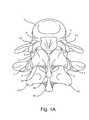
- FIG. 1is a perspective view of a portion of the spine
- FIG. 1Ais a dorsal view of the portion of the spine shown in FIG. 1 ;
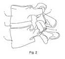
- FIG. 2is a lateral view of a facet joint reconstructed in accordance with the present invention.
- FIG. 3is a dorsal view of the facet joint shown in FIG. 2 ;
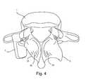
- FIG. 4is a perspective view of the implanted left inferior facet prosthesis shown in FIGS. 2 and 3 ;
- FIG. 5is a perspective view of the left inferior facet prosthesis shown in FIGS. 2 and 3 ;
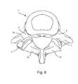
- FIG. 6is a cranial view of the implanted left superior facet prosthesis shown in FIGS. 2 and 3 ;
- FIG. 7is a perspective view of the left superior facet prosthesis shown in FIGS. 2 and 3 ;
- FIG. 8is a perspective view of an alternate implanted left inferior facet prosthesis
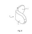
- FIG. 9is a perspective view of an alternate left inferior facet prosthesis
- FIG. 10is a lateral view of an alternative reconstructed facet joint
- FIG. 11is a dorsal view of an alternative reconstructed facet joint
- FIG. 12is a perspective view of the implanted left inferior facet prosthesis shown in FIGS. 10 and 11 ;
- FIG. 13is a perspective view of the alternative left inferior facet prosthesis shown in FIGS. 10 and 11 ;
- FIG. 14is a cranial view of the alternative implanted left superior facet prosthesis shown in FIGS. 10 and 11 ;
- FIG. 15is a perspective view of the alternative left superior facet prosthesis shown in FIGS. 10 and 11 ;
- FIG. 16is a perspective view of an alternate bearing surface for the superior facet prosthesis shown in FIG. 15 ;
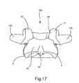
- FIG. 17is a dorsal view of a single intact vertebra
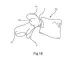
- FIG. 18is a lateral view of the same intact vertebra shown in FIG. 17 ;
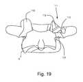
- FIG. 19is a dorsal view of the same vertebra of FIG. 17 and FIG. 18 , with a portion of the superior facet resected and a portion of the inferior facet resected;
- FIG. 20is a lateral view of the resected vertebra shown in FIG. 19 ;
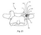
- FIG. 21is a dorsal view of the same resected vertebra shown in FIG. 18 and FIG. 19 with a fixation element placed through the first superior resection surface and into the pedicle bone;
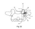
- FIG. 22is a dorsal view showing the resected vertebra, the fixation element, and a superior facet prosthesis
- FIG. 23is a dorsal view of the vertebra and the implant of FIG. 23 and also showing the addition of an inferior facet prosthesis;
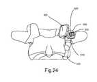
- FIG. 24is a dorsal view of the implant and vertebra of FIG. 23 and also showing the addition of an enlarged head that has the shape of a locking nut;
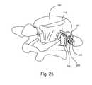
- FIG. 25is an isometric posteriolateral view of a vertebra with an assembled implant comprising a fixation element, superior facet prosthesis, and a locking nut;
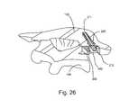
- FIG. 26is a cross-sectional view of the same vertebra and implant of FIG. 25 showing the result of a cross-sectional view cut aligned with the axis of the fixation element;
- FIG. 27is a view of the same cross-section described in FIG. 26 , aligned to face the viewer;
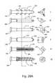
- FIG. 28is a side view of embodiments A, B, C, D, E, and F of the fixation element, and a cross-sectional view of the same embodiments, and a side view of the enlarged head in the shape of a locking nut;
- FIG. 28Ais a side view of embodiments G, H, I, J, K, and L of the fixation element with attached enlarged heads, and a cross-sectional view of the same embodiments;
- FIG. 29is an isometric view of a radially expanding fixation element in its unexpanded state
- FIG. 30is a side view and a bottom view of (i) an expanded radially expanding fixation element and (ii) an unexpanded radially expanding fixation element;
- FIG. 31is an isometric cross-sectional view of a vertebra and a facet implant showing a cross-pin torsionally and axially securing the fixation element;
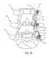
- FIG. 32is a dorsal view of a spinal section showing a top, middle, and bottom vertebra with unilateral facet replacements on the right side of the spine section, both between the top and middle vertebra, and between the middle and bottom vertebra;
- FIG. 33is a dorsal view of a spine section showing a superior hemiplasty facet replacement between the top and the middle vertebra and unilateral replacement between the middle and the bottom vertebra;
- FIG. 34is a dorsal view of a spinal section showing an inferior facet hemiplasty replacement between the top and the middle vertebra and a unilateral replacement on the right side between the middle and the bottom vertebra;
- FIG. 35is a dorsal view of a spinal section showing a unilateral replacement between the top and the middle vertebra on the right side, and an inferior facet hemiplasty replacement between the middle and the bottom vertebra on the same side;
- FIG. 36is a dorsal view of a spinal section showing a unilateral replacement between the top and the middle vertebra on the right side and a superior facet hemiplasty replacement on the right side between the middle and the bottom vertebra on the same side;
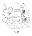
- FIG. 37is a spinal section of two vertebra showing the inferior facet of the top vertebra and the superior facet of the joining bottom vertebra replaced by an articulating facet implant;
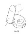
- FIG. 38is an isometric view of a curved superior facet prosthesis
- FIG. 39is an isometric view of the bone ingrowth surface on a superior facet prosthesis.
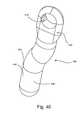
- FIG. 40is an isometric view of an inferior facet prosthesis
- FIG. 41is an isometric view of an inferior facet prosthesis with a bone ingrowth surface
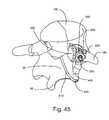
- FIG. 42shows the addition of a locking washer to the construction of the implant shown in FIG. 25 ;
- FIG. 43shows the assembly of the construct shown in FIG. 42 ;
- FIG. 44shows an isometric view of the locking washer shown in FIG. 42 ;
- FIG. 45shows superior and inferior facet prostheses held to a vertebra by flexible fixation elements
- FIG. 46is a dorsal view of a bilateral inferior implant.
- Vertebra 1has superior facets 43 , inferior facets 6 , posterior arch (or lamina) 35 and spinous process 46 .
- Vertebra 3has superior facets 7 , inferior facets 44 , posterior arch (or lamina) 36 and spinous process 45 .
- FIG. 2the left inferior facet 6 of vertebra 1 shown in FIG. 1 and FIG. 1A has been resected and inferior facet prosthesis 4 has been attached to vertebra 1 .
- the left superior facet 7 of vertebra 3has been resected and a superior facet prosthesis 5 has been attached to vertebra 3 .
- FIG. 3illustrates a dorsal view of the elements shown in FIG. 2 .
- inferior facet prosthesis 4replicates the natural anatomy when compared to the contralateral inferior facet 6 of vertebra 1 .
- superior facet prosthesis 5replicates the natural anatomy when compared to the contralateral superior facet 7 of vertebra 3 .
- Neither inferior facet prosthesis 4 nor superior facet prosthesis 5rests on the lamina.
- FIG. 4a perspective view of vertebra 1 with implanted inferior facet prosthesis 4 is provided.
- a bone resection on the left side of the vertebra 1shown as resection 31 , has removed the natural inferior facet 6 at the bony junction between the inferior facet 6 and the posterior arch (or lamina) 35 .
- any bone pain associated with a disease, such as osteoarthritis, or trauma of the left inferior facet 6will be eliminated as the involved bony tissue has been osteotomized.
- FIG. 5illustrates a perspective view of inferior facet prosthesis 4 .
- Surface 8replicates the natural articular surface of the replaced inferior facet 6 .
- Post 9provides a means to affix inferior facet prosthesis 4 to vertebra 1 .
- Post 9is implanted into the interior bone space of the left pedicle on vertebra 1 and may or may not extend into the vertebral body of vertebra 1 to provide additional stability.
- FIG. 6illustrates a cranial view of vertebra 3 with implanted superior facet prosthesis 5 .
- Resection surface 32represents the bony junction between the natural superior facet 7 and the posterior arch 35 .
- FIG. 7illustrates a perspective view of superior facet prosthesis 5 .
- Surface 36replicates the natural articular surface of the replaced superior facet 7 .
- Post 37provides a means for affixing superior facet prosthesis 5 to vertebra 3 .
- Post 37is implanted into the interior bone space of the left pedicle P ( FIG. 6 ) on vertebra 3 and may or may not extend into the vertebral body of vertebra 3 to provide additional stability.
- FIG. 8illustrates an alternative inferior facet prosthesis 10 which is implanted into the interior bone space of posterior arch (or lamina) 35 .
- the interior bone spaceis accessed from the resection 31 .
- FIG. 9shows details of alternative inferior facet prosthesis 10 , including the fin 13 that extends into the interior bone space of posterior arch 35 .
- Surface 12replicates the natural articular surface of the replaced facet.
- the surfaces of post 9 ( FIG. 5 ), post 37 ( FIG. 7 ) and fin 13 ( FIG. 9 )may or may not include porous coatings to facilitate bone ingrowth to enhance the long term fixation of the implant. Furthermore, such porous coatings may or may not include osteoinductive or osteoconductive substances to further enhance the bone remodeling into the porous coating.
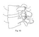
- FIG. 10there is shown a lateral view of a superior vertebra 14 and an inferior vertebra 16 , with an intervertebral disc 15 located in between.
- the left inferior facet of vertebra 14has been resected and an inferior facet prosthesis 18 has been attached to vertebra 14 by means of a screw fastener 17 .
- the left superior facet of vertebra 16has been resected and a superior facet prosthesis 19 has been attached to vertebra 16 by means of a screw fastener 17 .
- FIG. 11illustrates a dorsal view of the elements of FIG. 10 .
- inferior facet prosthesis 18replicates the natural anatomy when compared to the contralateral inferior facet 22 of vertebra 14 .
- superior facet prosthesis 19replicates the natural anatomy when compared to the contralateral superior facet 21 of vertebra 16 .
- Neither inferior facet prosthesis 18 nor superior facet prosthesis 19rests on the lamina.
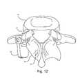
- FIG. 12there is provided a perspective view of vertebra 14 with implanted inferior facet prosthesis 18 .
- Resection 34has removed the natural inferior facet at the bony junction between the inferior facet and the posterior arch 37 .
- any bone pain associated with a disease, such as osteoarthritis, or trauma of the natural inferior facet 22will be eliminated inasmuch as the involved bony tissue has been osteotomized.
- FIG. 13illustrates a perspective view of inferior facet prosthesis 18 .
- Surface 23replicates the natural articular surface of the replaced facet.
- Flange 25contacts the pedicle P ( FIG. 12 ) and hole 24 receives a screw fastener 17 to attach inferior facet prosthesis 18 to vertebra 14 .
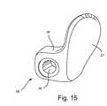
- FIG. 14illustrates a cranial view of vertebra 16 with implanted superior facet prosthesis 19 .
- Resection surface 35 Arepresents the bony junction between the natural superior facet 21 ( FIG. 11 ) and the posterior arch 38 .
- FIG. 15illustrates a perspective view of superior facet prosthesis 19 .
- Surface 27replicates the natural articular surface of the replaced facet.
- Flange 39contacts the pedicle P ( FIG. 14 ) and hole 26 receives a screw fastener 17 to attach superior facet prosthesis 19 to vertebra 16 .
- FIG. 16illustrates an alternative superior facet prosthesis 40 with a bearing surface 41 that mounts to substrate 42 .
- the bearing surface 41is a biocompatible polymeric material, such as ultra high molecular weight polyethylene. Alternately, the bearing surface can be ceramic, such as zirconia or alumina.
- the substrateis a biocompatible metal alloy, such as an alloy of titanium, cobalt, or iron.
- FIG. 17is a dorsal view of the vertebra 100 .
- FIG. 18is a lateral view of the same vertebra 100 .
- the vertebra 100has posterior anatomy comprising left and right superior facets 43 on the superior, or top side in this view of the dorsal vertebra 100 , left and right inferior facets 6 on the inferior or bottom side of the posterior vertebra 100 , left and right transverse processes 105 extending laterally from the posterior portion of vertebra 100 , and left and right pedicles P.
- the posterior portion of vertebra 100also has a posterior arch (or lamina) 35 , and a spinous process 46 that protrudes from the posterior arch 35 posteriorly, out of the page in FIG. 17 and to the left in FIG. 18 .
- the bony structure of the superior facets 43 and the inferior facets 6are intact, as it would be presented in a vertebra without significant tissue degeneration or remodeling resulting from facet joint disease.
- the vertebra 100is shown in FIG. 17 as a generally structurally healthy and intact vertebra, if the vertebra 100 were a diseased vertebra, the vertebra could exhibit signs of facet joint disease.
- the left superior facet 43 and the right superior facet 43 of the vertebra 100axe symmetrical in FIG. 17 and FIG. 18 .
- the facet on the diseased sidewould likely be showing pathological signs of disease such as tissue degeneration or inflammation resulting in an asymmetrical structural comparison between the two facets.
- the facet diseasecould progress to a state in which the articular process of the facet is eroded or inflamed resulting in anatomic morphology that is unique to the pathology of a particular facet joint of an individual patient.
- the facet diseasecould eventually disable the biomechanics of a patient such that the facet joint is essentially non-articulating and immobile.
- one superior facet of a first vertebracould essentially be fused to one inferior facet of a second vertebra.
- FIG. 19 and FIG. 20which are dorsal and lateral views, of the same vertebra shown in FIG. 17 and FIG. 18 after a portion of the right superior facet 43 and a portion of the right inferior facet 6 have been resected.
- the removal of a portion of the superior facet 43 by resectionresults in a superior facet resection 111 .
- the superior resection 111has two resulting faces, a first resection surface 112 and a second resection surface 113 .
- the interior facet resectionresults in an inferior facet resection surface 121 .
- Tissue removal toolssuch as a bone burr, rasp, reamer, mill, saw, rounger, osteotomy or similar tools designed to cut and remove bone tissue can be used to create these resection surfaces.
- the surgeonuses anatomic landmarks such as the pedicle P or transverse process 105 to align the tissue removal tools in such a way as to remove the portion of the facet necessary to provide a superior resection 111 that serves as a bone apposition surface or foundation to eventually support the superior facet prosthesis 300 , as shown in FIG. 22 .
- the left superior facet 43is shown intact in both FIG. 19 ) and FIG.
- first resection surface 112 and the second resection surface 113are on approximately perpendicular planes.
- the geometry of the resections surfacesare a function of the patient anatomy, the pathology of the diseased tissue, the technique of the surgeon, and other factors such as the type of tissue removal tools used to prepare the resection.
- first resection surface 112will be formed in such a way that it will serve as a foundation to support the superior facet prosthesis 300 ( FIG. 22 ).
- the second resection surface 113 or other additional resection surfacesmay or may not be present.
- FIG. 19 and FIG. 20also show that a portion of the inferior facet 6 is resected by tissue removal instruments resulting in an inferior resection surface 121 .
- tissue removal instrumentsresulting in an inferior resection surface 121 .
- Such resectionis preferably effected so that resection is confined to the tissue of inferior facet 6 and does not extend into the tissue of posterior arch (or lamina) 35 .
- the left inferior facet 6is intact, while a portion of the right inferior facet 6 is resected resulting in an inferior resection surface 121 on the right side.
- the bone surrounding the inferior resection surface 121is formed by tissue removal tools in a shape designed to cradle and support the inferior facet prosthesis 400 ( FIG. 23 ) on the medial side such that when the inferior facet prosthesis 400 is loaded on the lateral side it compresses against and is supported by the inferior resection surface 121 .
- inferior facet 6can be resected, and inferior facet prosthesis 400 sized and shaped, so that inferior facet prosthesis 400 does not engage inferior resection surface 121 .
- FIG. 21shows the vertebra 100 with a fixation element 200 portion of the facet implant placed through the superior resection 111 and into the bone of the pedicle P.
- the fixation element 200is aligned and placed into the pedicle, similar to how other pedicle screws for posterior stabilization involved with vertebrae fusion are placed in the pedicle.
- a long guide wire(not shown), with a diameter sized to fit freely into a cannulation 211 (as shown in FIG. 26 and FIG. 27 ) in the fixation element 200 , is placed through the first resection surface 112 and into the pedicle bone P.
- the alignment of the long guide wirecan be confirmed by x-ray.
- the fixation element 200is then guided over the guide wire and driven into the vertebra by a driver (not shown) engaged with the drive feature 212 ( FIG. 21 ) on the proximal post 230 of the fixation element 200 .
- the fixation element 200is driven into the vertebra until a connection feature 213 (e.g., a screw thread) is just above the first resection surface 112 .
- This connection feature 213is eventually used to secure the superior facet prosthesis 300 to the vertebra 100 .
- a long guide wire(not shown), with a diameter sized to fit freely into a cannulation in a bone preparation instrument (not shown) such as a lap, drill, broach or reamer, is placed through the first resection surface 112 and into the pedicle bone P.
- the alignment of the long guide wirecan be confirmed by x-ray.
- the bone preparation instrumentis then guided over the guide wire and driven into the pedicle P bone to prepare a cavity for the fixation element 200 .
- the guide wire and bone preparation instrumentare then removed and the fixation element 200 is guided into the prepared cavity in the pedicle bone P by a driver (not shown) engaged with the drive feature 212 on the proximal post 230 of the fixation element 200 .
- the fixation element 200is driven into the vertebra until a connection feature 213 (e.g., a screw thread) is just above the first resection surface 112 .
- This connection feature 213is eventually used to secure the superior facet prosthesis 300 to the vertebra 100 .
- the surgeonaligns the fixation element 200 with anatomic landmarks and simply drives the fixation element 200 through the first resected surface 112 and into the pedicle bone P.
- the fixation element 200is driven into the vertebra until a connection feature 213 (e.g., a screw thread) is just above the first superior resection surface 112 .
- a superior facet prosthesis 300is shown placed around the fixation element 200 .
- the superior facet prosthesis 300has a facet articulating component 320 that articulates with the inferior facet articulating surface of the vertebra above it. Facet articulating component 320 is preferably formed in the general shape of a blade or wing ear.
- the superior facet prosthesis 300also has a bone apposition surface 322 that has been placed on the first resection surface 112 and an opening 324 in a flange 323 that surrounds the fixation element 200 .
- the superior facet articulating component 320has an articulating surface 321 generally adjacent to the flange 323 that is orientated in a direction that faces approximately the same direction that the original anatomic superior articulating surface 145 faced prior to resection.
- This orientation of the articulating surface 321allows the superior facet prosthesis 300 to function as either a hemiplasty implant and articulate against a natural anatomic inferior facet 6 or act as a unilateral prosthesis and articulate against an inferior facet prosthesis 400 on the vertebra superior (cephalad) to it. No portion of superior facet prosthesis 300 rests on the lamina.
- FIG. 23shows the addition of the inferior facet prosthesis 400 to the construct described in FIG. 22 .
- the inferior facet prosthesis 400generally has a shape similar to a longitudinal rod that is curved to match the contour of the inferior resection 121 ( FIGS. 19 and 20 ).
- the inferior facet prosthesis 400has an opening 410 through its superior end 420 that is shaped to surround the portion of the fixation element 200 that protrudes from the first resection surface 112 .
- the inferior facet prosthesis 400is placed over the superior facet prosthesis 300 .
- the order of the placement of the prosthesescan be reversed such that the inferior prosthesis 400 is placed on the fixation element 200 first followed by the superior prosthesis 300 .
- only the inferior facet 6 or the superior facet 43is being replaced, only the appropriate (superior or inferior) facet prosthesis is placed on the fixation element 200 without the other (inferior or superior) facet prosthesis.
- the various components of the implantare modular, many combinations of configurations and implant size, structure and shapes are feasible.
- the inferior facet prosthesis 400may need to be larger than expected to conform to a particularly unusual or exceptionally large morphology of the inferior resection surface 121 , and the superior facet prosthesis 300 may need to have an unusual angle to its articulating surface to conform to particular anatomic constraints.
- the modularity of the systemallows for the surgeon to assemble an implant specifically designed to match the patient's anatomic structures during the surgery. This flexibility of a modular implant design allows the implant manufacturer to accommodate a large variation in anatomic structures with a limited selection of implant component sizes, shapes, and material types.
- fixation implantssuch as the fixation element 300 are fabricated from biocompatible metals or alloys that provide sufficient strength and fatigue properties, such as cobalt chrome alloys, titanium and titanium alloys, and stainless steels.
- the fixation element 300may be fabricated from ceramics, polymers, or biological materials such as allograft bone, composites, or other biocompatible structural materials.
- the superior facet prosthesis 300 and the inferior facet prosthesis 400may be fabricated from metals, alloys, ceramics, polymers, biological materials, composites, or other biocompatible structural materials.
- an enlarged head 500is added to the fixation element 200 and is tightened down to force the prosthesis or prostheses into the bone to stabilize them.
- the enlarged head 500 shown in FIG. 24has a hexagonal geometry on its external surface that is shaped to accept a driver (not shown) that is used to force an internal connection feature 520 (e.g., a screw thread) of the enlarged head 500 onto the connection feature 213 of the fixation element 200 .
- the enlarged head 500is provided with a threaded connection feature 520 and is driven onto the fixation element 200 by turning the enlarged head 500 and allowing the threads to drive all components of the implant between the enlarged head 500 and the first resection surface 112 into the bone at or near the resection surface 112 .
- FIG. 25is an isometric posterior view of the assembly of the fixation element 200 , the superior facet prosthesis 300 , and the enlarged head 500 placed on the first resection surface 112 .
- FIG. 26is the same construct shown in FIG. 25 , but with the implants and the vertebra 100 cut by a cross-sectioning plane 150 placed along an axis that passes through the center of the fixation element 200 .
- the cross-section plan 150 shown cutting through the vertebra 100 and the implant in FIG. 26is shown for visualization purposes to illustrate, using a cross-sectioned view, how the vertebra 100 , fixation element 200 , superior facet prosthesis 300 and the enlarged head 500 engage with each other. In actual surgery, it is highly unlikely that a surgeon would make a cut as illustrated by the cross-section 150 shown in FIG. 26 .
- FIG. 27is a view of the vertebra 100 and the implant wherein the cross-section 150 shown in FIG. 26 is orientated such that the cross-section plane is facing the viewer.
- the fixation element 200is in the vertebra 100 .
- the embodiment of the fixation element 200 in FIG. 27comprises a distal end 220 that is shaped to guide the fixation element 200 into bone tissue, a bone stabilizing portion 210 adjacent and proximal to the distal end, a shaft portion 240 adjacent and proximal to the bone stabilizing portion 210 , a connection feature 213 adjacent and proximal to the shaft portion 240 , and a drive feature 212 .
- the distal end 220 shown in FIG. 27has a frustro-conical shape that allows the fixation element 200 to be driven or guided into the vertebra 100 .
- the distal end 220could be shaped in the form of a spade tip, trochar tip, or twist drill tip to assist in the guidance of the fixation element 200 in the vertebra 100 .
- the fixation element 200may also have a cutting flute (not shown) formed in the distal end 220 to help remove bone tissue and accommodate the guidance of the fixation element 200 in the vertebra 100 .
- the fixation element 200has a stabilizing portion 210 to help secure the fixation element 200 to the vertebra 100 .
- This stabilizing portion 210is a structure that can be the shape of various features that are designed to anchor into bone such as threads, ribs, grooves, slots, fins, barbs, splines, bone ingrowth surfaces, roughened surfaces, or any geometric feature that helps to engage the fixation element 200 with the bone tissue to help stabilize the fixation element 200 .
- the stabilizing portion 210is shown as a unitary continuous bone thread 231 .
- other types of threadssuch as multiple lead threads, variable pitched thread, non-uniform pitch thread, buttress thread, or other thread forms, used on bone screws may be used. Because FIG. 27 is a cross-sectional view, the full length of the cannulation 211 is seen passing from the distal end 220 of the fixation element 200 to the proximal post 230 of the fixation element 200 .
- the drive feature 212 in the embodiment shown in FIG. 27is an internal hex. However, any shape of drive feature 212 that transmits the loads necessary to drive the fixation element 200 into the vertebra can be formed on the proximal post 230 of the fixation element 200 .
- the depth of the drive feature 212 formed in the proximal post 230 of the fixation element 200is seen in the cross-sectional view of FIG. 27 .
- the drive feature 212may be an internal drive feature such as the hex socket shown in this embodiment, or an external drive feature with geometry on the periphery of the proximal post 230 of the fixation element 200 that engages with a corresponding internal drive feature on a driver tool (not shown).
- the depth of the drive feature 212is slightly longer than its cross-section is wide. This depth can be adjusted based on the material properties of the fixation element 200 and the drive tool (not shown).
- the fixation element 200is fabricated from biocompatible base materials that allow for the structural rigidity and strength needed.
- base materials that the fixation element 200 are made frominclude titanium, titanium alloys, cobalt-chrome alloys, stainless steel alloys, zirconium alloys, other biocompatible metal materials, biocompatible ceramics, biocompatible composites, and biocompatible polymers.
- the fixation element 200may also have surface materials formed on the base material that allow for material properties specific to a particular portion of the fixation element 200 .
- the bone stabilization portion 210could be coated with materials that allow for improved bone ingrowth into the implant surface such as a hydroxylapatite, bioceramic, Bioglass®, or other calcium phosphate derived material.
- the tribological bearing properties of the material in the areas that the fixation element 200 interfaces with other artificial elementsmay be improved by applying surface hardening techniques to the material of the fixation element 200 in these areas.
- Surface hardening techniques known in the materials science and materials engineering artssuch as anodizing, ion implantation, and other techniques could be applied to these isolated areas.
- connection feature 213is formed on the portion of the fixation element 200 that protrudes from the first resection surface 112 .
- This connection feature 213is designed to connect the enlarged head 500 to the fixation element 200 .
- threads 260are on the external surface of this proximal section of the fixation element 200 . These threads 260 engage with the threads on the internal connection feature 520 ( FIG. 27 ) of the enlarged head 500 .
- connection feature 213 in this embodimentis threaded
- other mechanical locking featurescapable of locking the fixation element 200 and the enlarged head 500 together, such as press fit, taper fit, bonding fit by cement or glue, interference fit, expansion fit and mechanical interlocking fit such as a bayonet connection, can be used as the connection feature 213 (and a corresponding construction used on connection feature 520 of head 500 ).
- FIG. 27Also shown in FIG. 27 is a cross-sectional view of an embodiment of the superior facet prosthesis 300 .
- This embodiment of the superior facet prosthesis 300has a flange 323 that has an opening 324 that wraps around the fixation element 200 .
- the flange 323is positioned such that its bone contacting surface 322 makes contact with the first resection surface 112 .
- other embodiments of the superior facet prosthesis 300have structures (e.g., spikes) that protrude into the first resection surface 112 to help resist torsion and other anatomic loads.
- the articulating component 320Protruding from the flange 323 at a given angle ⁇ , and a given distance X from the opening 324 , is an articulating component 320 .
- the articulating component 320has an articulating surface 321 that replicates the natural articular surface of the replaced facet.
- the enlarged head 500in this embodiment has an internal connection feature 520 and a hexagonal shaped external drive feature 511 C that is used to drive the enlarged head 500 over the fixation element 200 and against the superior facet prosthesis 300 .
- the specific shape of the external drive feature 510is dependent on the mating shape of the driver (not shown).
- FIG. 28six different embodiments of the bone stabilization portion 210 of the fixation element 200 are shown that are labeled A, B, C, D, E, and F.
- the figureshows a side view of each fixation element 200 embodiment and a cross-sectional view of each embodiment to the right of the respective side view.
- To the left of the six embodimentsis a representative enlarged head 500 .
- Embodiment Ais the threaded fixation element 200 embodiment shown in FIGS. 26 and 27 and described above.
- Embodiments B through Eare various designs of fixation elements with non-circular cross-sections.
- Embodiment Bis a four rib cruciate design with four longitudinal fins configured to resist torsion when the fixation element 200 is in the vertebra 100 .
- Embodiment Cis an oval shaped cross-section design that is wider in the first direction than the second direction to resist torsion. If the dimension of the width in the first and second directions is equal, the cross-section shape becomes more of a circle and bone stabilization portion 210 becomes more of a press-fit peg.
- Embodiment Dis a square cross-section design with four approximately perpendicular sides, The corners of the sides help to resist torsion.
- Embodiment Eis a triangular cross-section design with three sides to resist torsion.
- Embodiment Fis an anchor-like design that is driven into the vertebra, with the wire arches or barbs 290 being compressed against the host bone and applying a radial expansion force so as to lock the structure to the bone.
- FIG. 28Ashows a side view of each fixation element 200 embodiment and a cross-sectional view of each embodiment to the right of the respective side view. Each embodiment has an attached enlarged head 500 .
- Embodiment Gis similar to the threaded fixation element 200 embodiment shown in FIGS. 10 , 11 , 12 and 24 and described above.
- Embodiments H through Kare various designs of fixation elements 200 with non-circular cross-sections.
- Embodiment His a four rib cruciate design with four longitudinal fins 285 configured to resist torsion when the fixation element 200 is in the vertebra 100 .
- Embodiment Iis an oval shaped cross-section design that is wider in the first direction 286 than the second direction 287 to resist torsion. If the dimension of the width in the first direction 286 and second direction 287 is equal, the cross-section shape becomes more of a circle and bone stabilization portion 210 becomes more of a press-fit peg.
- Embodiment Jis a square cross-section design with four approximately perpendicular sides 288 . The corners 289 of the sides 288 help to resist torsion.
- Embodiment Kis a triangular cross-section design with three sides 291 to resist torsion.
- Embodiment Lis an anchor-like design that is similar to Embodiment F in FIG. 28 , but with an attached enlarged head 500 ′. As embodiment L is, driven into the vertebra, wire arches or barbs 290 are compressed and apply radial expansion force against the wall of the prepared bone and into the pedicle bone P resulting in a locking anchor.
- FIG. 29is an isometric view of a radially expanding fixation element 600 .
- the radially expanding fixation element 600comprises two main elements, an expansion sleeve 620 and a central element 610 that is inside of the expansion sleeve 620 .
- the radially expanding fixation element 600is placed into the vertebra and then the central element 610 is pulled relative to the expansion sleeve 620 resulting in radial expansion of the fixation element 600 . This is shown in FIG. 30 .
- talons 621 on the expansion sleeve 620are radially expanded outward by a mandrel 660 on the central element 610 .
- the talons or fingers 621provide both torsional and axial stability to the radially expanding fixation element 600 . This provides a secure fixation element for fixation of the remaining components of the implant.
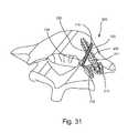
- FIG. 31shows a cross-pin element 700 engaged with the fixation element 200 to help secure the fixation element 200 both torsionally and axially.
- the cross-pin element 700is columnar in shape having a distal end 710 , mid section 730 (with a length along its longitudinal axis that is longer than its transverse cross-sectional width), and a proximal post 720 .
- the distal end 710is shaped to penetrate through bone tissue and into a cross hole 280 formed in the fixation element 200 .
- Instrumentation(not shown) is used to align the cross-pin element 700 with the cross-hole 280 by fixing to the drive feature 212 or the cannulation 211 on the fixation element 200 and aligning the direction of insertion of the cross-pin element 700 with the cross-hole 280 .
- FIGS. 32 through 37show a fixation element 200 and enlarged head 500 as the means of securing the prostheses to the vertebra
- other clamping meanssuch as the screw fastener 17 ( FIG. 10 ) may be used to mount the prosthesis to the bone.
- the screw prostheses 17 shown in FIGS. 10 through 12passes through either the opening 324 ( FIG. 22 ) in the superior facet prosthesis 300 or the opening 410 ( FIG. 23 ) in the inferior facet prosthesis 400 or through both of these openings wherein the head of the screw fastener 17 acts as the securing means pressing the inferior facet prostheses 400 and the superior facet prosthesis 300 against their respective resection surfaces.
- FIGS. 32 through 37demonstrate different combinations of assemblies of the facet replacement prosthesis.
- the basic components of the prosthesisare the fixation element 200 , superior facet prosthesis 300 , inferior facet prosthesis 400 , and the enlarged head 500 .
- a screw fastener 17can replace the fixation element 200 and the enlarged head 500 .
- top vertebra 101is above the middle vertebra 102 that is shown above the bottom vertebra 103 .
- portions of some of the facets on the right side of the vertebraeare replaced by prostheses.
- inferior facet prosthesis 401is articulating against superior facet prosthesis 302 to form an artificial unilateral joint.
- the inferior facet of the middle vertebra 102is replaced by inferior facet prosthesis 402 and the superior facet of the bottom vertebra 103 is replaced by superior facet prosthesis 303 .
- FIG. 32demonstrates the difference in shape of the inferior facet prosthesis 401 that is; implanted around the fixation element 201 without a superior facet prosthesis 300 and an inferior facet prosthesis 402 that is implanted around a fixation element 202 and over a superior facet prosthesis 302 .
- the opening 410 of the inferior facet prosthesis 401 on the top vertebra 101 in this assemblyis offset more laterally than the opening 410 in the inferior facet prosthesis 402 for the middle vertebra 102 . This is because the fixation element 201 is implanted more laterally on the top vertebra 101 to preserve more of the superior facet since it is not replaced by a prosthesis at this level.
- the top vertebra 101is left intact without resection of the facets. Portions of both the superior and inferior facets on the right side of the middle vertebra 102 are replaced by superior facet prosthesis 302 and an inferior facet prosthesis 402 . Only the right superior facet of the bottom vertebra 103 is replaced (i.e., by a superior facet prosthesis 303 ) in FIG. 33 . Thus, a hemiplasty replacement results on the right facet joint between the top vertebra 101 and the middle vertebra 102 and a unilateral replacement results between the middle vertebra 102 and the bottom vertebra 103 .
- This assembly shown in FIG. 33demonstrates how the superior facet prosthesis 302 can articulate against a natural inferior facet 6 or superior facet prosthesis 303 can articulate against an inferior facet prosthesis 402 .
- FIG. 34shows how an inferior facet prosthesis 401 can articulate against a natural superior facet 43 , or a inferior facet prosthesis 402 can articulate against superior facet prosthesis 303 .
- the right facet joint between the top vertebra 101 and the middle vertebra 102is a hemiplasty replacement with the inferior facet replaced by an inferior facet prosthesis 401 .
- the right facet joint between the middle vertebra 102 and the bottom vertebra 103is a unilateral replacement with the inferior facet replaced by in inferior facet prosthesis 402 and the superior facet of the bottom vertebra 103 replaced by a superior facet prosthesis 303 .
- FIG. 35shows another example of how the superior facet prosthesis 303 can articulate against a natural inferior facet 6 or superior facet prosthesis 302 can articulate against an inferior facet prosthesis 401 .
- the right side between the top vertebra 101 and the middle vertebra 102is a unilateral replacement and the right side between the middle vertebra 102 and the bottom vertebra 103 is a hemiplasty replacement.
- FIG. 36shows another example of how an inferior facet prosthesis 402 can articulate against a natural superior facet 43 , or an inferior facet prosthesis 401 can articulate against superior facet prosthesis 302 .
- the right facet joint between the top vertebra 101 and the middle vertebra 102is an unilateral replacement with the inferior facet replaced by an inferior facet prosthesis 401 and the superior facet of the middle vertebra 102 replaced by a superior facet prosthesis 302 .
- the right facet joint between the middle vertebra 102 and the bottom vertebra 103is a hemiplasty replacement with the inferior facet replaced by an inferior facet prosthesis 402 .
- the assembly of the implant shown in FIG. 37demonstrates only one level, that between the middle vertebra 102 and the bottom vertebra 103 , being replaced on the right side
- FIG. 38 and FIG. 39show two embodiments of the superior facet prosthesis.
- the embodiment shown in FIG. 38is curved superior facet prosthesis 305 with a curved articulating component 320 that has a curved articulating surface 321 .
- This curved articulating surface 321allows for a more distributed contact load between an inferior facet prosthesis 400 and the curved articulating surface 321 .
- the articulating surface 321 of the superior facet prosthesis 300 previously describedis relatively flat.
- the articulating surface 221 of the curved superior facet prosthesis 305is curved. Since the bearing portion of the inferior facet prosthesis 400 is columnar, the two prosthesis can be aligned on a slight mismatch and make more of an anatomic contact if the articulated surface is curved as in FIG. 38 .
- FIG. 39illustrates bone ingrowth feature 390 on the superior facet prosthesis 306 .
- This bone ingrowth featurecan be any surface that allows bone to grow into the implant between the first resection 111 of the vertebra and the 322 bone-contacting surface 321 of the implant.
- Examples of bone ingrowth features 390include porous coating of beads or meshes, electrochemically etched shapes and porous pads pressed onto the implant surface made from tantalum, titanium, cobalt chrome alloys or and other biocompatible material such as hydroxylapatite or calcium phosphate ceramics.
- FIG. 40shows an isometric view of an inferior facet prosthesis 400 formed in the general shape of a finger or talon. More particularly, inferior facet prosthesis 400 is formed with a flange 420 on its superior side shaped to either fit between the superior facet prosthesis 300 and the enlarged head 500 , or between the first resection surface 112 and the enlarged head 500 .
- the flange 420has an opening 410 through it that is dimensioned to allow the inferior facet prosthesis 400 to fit over the proximal end 210 or the fixation element 200 and around the post of the fixation element 200 .
- the inferior facet prosthesis 400also has an inferior portion 450 on the opposite side of the flange 420 that has a bone apposition side 440 that is shaped to contact the surface of the resected bone 121 ( FIG. 19 ) and joint articulation side 430 that is shaped to articulate with a natural or prosthetic superior facet.
- FIG. 41shows an isometric view of an inferior facet prosthesis 400 also formed in the general shape of a finger or talon.
- Inferior facet prosthesis 400is formed with a superior end 420 having an opening 410 that is dimensioned and shaped to accept the fixation element 200 .
- the inferior facet prosthesisis generally columnar in shape, having a curved length designed to conform to the prepared anatomy of the vertebra 100 .
- the inferior facet prosthesis 400 of FIG. 41has an inferior portion 450 , which is shown opposite the superior end 420 , and slightly medially offset from the superior end 420 .
- the inferior facet prosthesis embodiment of FIG. 41has a bone ingrowth surface 441 and an articulating surface 430 on its inferior end 450 .
- the bone ingrowth surface 441is a textured structure that permits bone cells to grow into the implant surface.
- the shape of the bone ingrowth surface 441can be a uniform textured surface as shown in FIG.
- the bone ingrowth surfaceis shaped to mate with the inferior resected bone surface 121 such as shown in FIG. 19 and FIG. 20 .
- FIG. 42shows a posterior isometric view of an embodiment of the superior facet implant 300 that has an additional locking washer 800 to assist in stabilizing the superior facet implant to the first resection surface 112 .
- the construction of the implant assembly shown in FIG. 42is similar to that of the assembly shown in FIG. 25 with the addition of the locking washer 800 that is placed over and around the superior facet implant 300 .
- FIG. 43shows the same implant of FIG. 42 with the enlarged head 500 locked onto the fixation element 200 and pushing the locking washer 800 against the superior prosthesis 300 and into the bone tissue. This added bone penetration of the locking washer 800 helps to fix the superior prosthesis 300 such that the entire assembly is more mechanically stable with respect to the vertebra 100 .
- FIG. 43shows a further step in the assembly of the implant construct described in FIG. 42 .
- the locking washer 800is secured over the fixation element 200 and into the bone tissue by the enlarged head 500 .
- the locking washer 800can also be used to mechanically secure the inferior facet prosthesis 400 and the combination of the inferior facet prosthesis 400 and the superior facet prosthesis 300 .
- the locking washer 800is placed over the superior facet prosthesis 300 .
- the locking washer 800may be placed under the superior facet prosthesis 300 or under any other combination of inferior facet prosthesis 400 and superior facet prosthesis 300 , or between the superior facet prosthesis 300 and the inferior facet prosthesis 400 to stabilize the implant construct.
- FIG. 44shows an isometric view of the locking washer 800 .
- the locking washed 800has an opening 810 in the body 805 that is dimensioned to fit over the proximal post 230 of the fixation element 200 .
- the locking washer 800also has an anti-rotation feature 820 that mates with either the superior facet prosthesis 300 or the inferior facet prosthesis 400 or a combination of both the inferior facet prosthesis 400 and the superior facet prosthesis 400 .
- the anti-rotation feature 820 shown in this embodimentis a flat surface, however, any feature that would rotationally constrain the locking washer 800 to the other components of the implant (such as a tab, groove, taper or other geometric shape) can be formed on the washer as a anti-rotation feature 820 .
- the locking washer 800also has prongs 830 that pass into the bone tissue of vertebra 100 to help stabilize the implant construct.
- the prongs in this embodiment of the locking washer 800are elongated protrusions that taper to a tissue penetration tip 840 .
- the prongshave sidewalls 850 that provide a surface to resist torsion once the locking washer 800 penetrates the bone tissue.
- the prongs 830may also be simple spikes that are either symmetrical or nonsymmetrical in cross-section that protrude from the locking washer body 805 .
- the shape and length of the locking washer prongs 830is dependent on how the locking washer is used.
- the prongs 830 of the locking washer 800 that holds only one of the inferior facet prosthesis 400 or the superior facet prosthesis 300 to the vertebra 100may be shorter than the prongs 830 of the locking washer 800 that holds both the inferior facet prosthesis 400 and the superior facet prosthesis 300 to the vertebra 100 .
- FIG. 45shows the superior facet prosthesis 300 and inferior facet prosthesis 400 held to the vertebra 100 by adjunctive flexible fixation element 900 and secondary flexible fixation element 910 .
- These flexible fixation elements 900 and/or 910may be made from such constructs as suture, braided cable, wire, ribbon, and other constructs that have longer lengths than cross-sections and withstand larger loads in tension than in compression.
- the flexible fixation element 900 and/or 910may be manufactured from biocompatible metals, alloys such as cobalt chrome alloys, titanium alloys, stainless steel alloys, polymers, bioabsorbale materials, composites, or other materials that are biocompatible and can be formed into a flexible element structure 900 and/or 910 such as those shown in FIG. 45 .
- the adjunctive flexible element 900 shown in FIG. 45is shown attached to and securing the elongated head 500 .
- a flexible element attachment portion 580(e.g., including an opening) mates the flexible element 900 to the elongated head.
- the adjunctive flexible fixation element 900may attach to and add adjunctive fixation element 900 to the fixation element 200 , the superior facet prosthesis 300 , the inferior facet prosthesis 400 or a combination of the above listed elements of the prosthesis.
- a flexible fixation attachment portion 480(e.g., including an opening) in the inferior facet prosthesis 400 allows the secondary flexible fixation element 910 to secure the inferior facet prostheses 400 to the vertebra 100 .
- the flexible fixation elements 900 and/or 910may be secured to the vertebra 100 by physically wrapping around anatomic features such as the posterior arch 35 , the spinous process 46 , or transverse process 105 or a combination of these anatomic features.
- the flexible element 900 and secondary flexible element 910may also be secured to the vertebra by bone anchors such as anchors designed to anchor flexible fixation elements (such as suture) to bone.
- Suture anchorssuch as threaded suture anchors, barbed suture anchors, toggle suture anchors or any other means of anchoring a flexible fixation element to bone may be used to anchor the flexible fixation element 900 or the secondary flexible fixation element 910 to the vertebra 100 .
- FIG. 46is a dorsal view of a bilateral inferior facet prosthesis 1000 .
- the bilateral inferior facet prosthesis 1000is a one-piece inferior facet prosthesis that has both a right inferior side 1040 and a left inferior side 1020 connected by a stabilizing bar 1010 . Both the right inferior side 1040 and the left inferior side 1020 are designed to fix to the vertebra at the respective inferior resection surface 121 ( FIG. 19 ) and the first resection surface 112 .
- the bilateral inferior prosthesisis a design that allows replacement of both the left and the right inferior facet. In this embodiment, the bilateral inferior prosthesis is placed over the left and right fixation elements 200 which extend into the top vertebra 101 . In this embodiment shown in FIG.
- the right inferior sideis articulating with a right superior facet prosthesis 300 attached to the lower vertebra 102 .
- the left inferior side 1020is articulating with the left natural superior facet 43 of the lower vertebra 102 .
- the stabilizing bar 1010 of the bilateral inferior prosthesis 1000is designed to stabilize the left side 1020 and the right side 1040 so that they are secure.
Landscapes
- Health & Medical Sciences (AREA)
- Orthopedic Medicine & Surgery (AREA)
- Life Sciences & Earth Sciences (AREA)
- Engineering & Computer Science (AREA)
- Biomedical Technology (AREA)
- Neurology (AREA)
- Public Health (AREA)
- Heart & Thoracic Surgery (AREA)
- Veterinary Medicine (AREA)
- Animal Behavior & Ethology (AREA)
- General Health & Medical Sciences (AREA)
- Surgery (AREA)
- Transplantation (AREA)
- Cardiology (AREA)
- Oral & Maxillofacial Surgery (AREA)
- Vascular Medicine (AREA)
- Molecular Biology (AREA)
- Medical Informatics (AREA)
- Nuclear Medicine, Radiotherapy & Molecular Imaging (AREA)
- Physical Education & Sports Medicine (AREA)
- Prostheses (AREA)
- Surgical Instruments (AREA)
Abstract
Description
- an articulating surface that articulates with another facet;
- a bone contacting surface that contacts a surface of the vertebra, said articulating surface being connected to said bone contacting surface; and
- a fixation element that attaches said bone contacting surface to the vertebra, said fixation element being adapted for implantation into an interior bone space of a pedicle of the vertebra;
- wherein said bone contacting surface is configured to engage a resected surface of the vertebra.
- an articulating surface that articulates with another facet;
- a bone contacting surface that contacts a surface of the vertebra, said articulating surface being connected to said bone contacting surface; and
- as fixation element that attaches said bone contacting surface to the vertebra, said fixation element being adapted for implantation into an interior bone space of a pedicle of the vertebra;
- wherein said bone contacting surface has a smaller surface area than said articulating surface.
- an articulating surface that articulates with another facet;
- a bone contacting surface that contacts a surface of the vertebra, said articulating surface being connected to said bone contacting surface; and
- a fixation element that attaches said bone contacting surface to the vertebra, said fixation element being adapted for implantation into an interior bone space of a pedicle of the vertebra;
- wherein said articulating surface comprises a wing ear extending upward from said bone contacting surface.
- an articulating surface that articulates with another facet;
- a bone contacting surface that contacts a surface of the vertebra, said articulating surface being connected to said bone contacting surface; and
- a fixation element that attaches said bone contacting surface to the vertebra, said fixation element being adapted for implantation into an interior bone space of a pedicle of the vertebra;
- wherein said articulating surface is substantially planar and extends adjacent to the pedicle.
- an articulating surface that articulates with another facet;
- a bone contacting surface that contacts a surface of the vertebra, said articulating surface being connected to said bone contacting surface; and
- a fixation element that attaches said bone contacting surface to the vertebra, said fixation element being adapted for implantation into an interior bone space of a pedicle of the vertebra;
- wherein said articulating surface is substantially planar and extends substantially parallel to said fixation element.
- an articulating surface that articulates with another facet;
- a bone contacting surface that contacts a surface of the vertebra, said articulating surface being connected to said bone contacting surface; and
- a fixation element that attaches said bone contacting surface to the vertebra, said fixation element being adapted for implantation into an interior bone space of a pedicle of the vertebra;
- wherein said fixation element clamps said bone contacting surface to a resected surface of the vertebra.
- an articulating element that articulates with another facet;
- a bone contacting element that contacts a surface of the vertebra, said articulating element being connected to said bone contacting element; and
- a fixation element that attaches said bone contacting element to the vertebra, said fixation element being adapted for implantation into an interior bone space of a pedicle of the vertebra;
- wherein said prosthesis is configured so that no portion of said prosthesis contacts the posterior arch of said vertebra.
- a superior articulating element that articulates with another facet;
- a superior bone contacting element that contacts one of a surface of the vertebra or another element contacting a surface of the vertebra, said superior articulating element being connected to said superior bone contacting element; and
- an inferior articulating element that articulates with another facet;
- an inferior bone contacting element that contacts one of a surface of the vertebra or another element contacting a surface of the vertebra, said inferior articulating element being connected to said inferior bone contacting element; and
- a fixation element that attaches said superior bone contacting element and said inferior bone contacting element to the vertebra, said fixation element being adapted for implantation into an interior bone space of a pedicle of the vertebra;
- wherein said prosthesis is configured so that no portion of said prosthesis contacts the posterior arch of said vertebra.
- a superior articulating element that articulates with another facet;
- a superior bone contacting element that contacts one of a surface of the first vertebra or another element contacting a surface of the vertebra, said superior articulating element being connected to said superior bone contacting element;
- a first fixation element that attaches said superior bone contacting element to the first vertebra, said first fixation element being adapted for implantation into an interior bone space of a pedicle of the vertebra; and
- an inferior articulating element that articulates with another facet;
- an inferior bone contacting element that contacts one of a surface of the second vertebra or another element contacting a surface of the vertebra, said inferior articulating element being connected to said inferior bone contacting element; and
- a second fixation element that attaches said inferior bone contacting element to the second vertebra, said second fixation element being adapted for implantation into an interior bone space of a pedicle of the vertebra; and
- wherein said prosthesis is configured so that no portion of said prosthesis contacts the posterior arches of said first and second vertebrae.
- providing:
- an articulating surface that articulates with another facet;
- a bone contacting surface that contacts a surface of the vertebra, said articulating surface being connected to said bone contacting surface; and
- a fixation element that attaches said bone contacting surface to the vertebra, said fixation element being adapted for implantation into an interior bone space of a pedicle of the vertebra;
- wherein said prosthesis is configured so that no portion of said prosthesis contacts the posterior arch of said vertebra; and
- positioning said bone contacting surface against a surface of the vertebra; and
- attaching said bone contacting surface to the vertebra using said fixation element.
- an articulating element that articulates with another facet;
- a bone contacting element that contacts a surface of the vertebra or another element contacting a surface of the vertebra, said articulating element being connected to said bone contacting element; and
- a fixation element that attaches said bone contacting element to the vertebra, said fixation element being adapted for implantation into an interior bone space of a pedicle of the vertebra;
- wherein said prosthesis is configured so that no portion of said prosthesis contacts the posterior arch of said vertebra.
- an articulating element that articulates with another facet;
- a bone contacting element that contacts a surface of the vertebra or another element contacting a surface of the vertebra, said articulating element being connected to said bone contacting element; and
- a fixation element that attaches said bone contacting element to the vertebra, said fixation element being adapted for implantation into an interior bone space of a pedicle of the vertebra;
- wherein said prosthesis is configured so that no portion of said prosthesis contacts the posterior arch of said vertebra;
- positioning said bone contacting surface against a surface of the vertebra or another element contacting a surface of the vertebra; and
- attaching said bone contacting surface to the vertebra using said fixation element.
Claims (15)
Priority Applications (4)
| Application Number | Priority Date | Filing Date | Title |
|---|---|---|---|
| US11/670,292US8556936B2 (en) | 2000-11-29 | 2007-02-01 | Facet joint replacement |
| US13/963,655US9241741B2 (en) | 2000-11-29 | 2013-08-09 | Facet joint replacement |
| US14/700,509US9668874B2 (en) | 2000-11-29 | 2015-04-30 | Facet joint replacement |
| US15/584,577US20170231776A1 (en) | 2000-11-29 | 2017-05-02 | Facet joint replacement |
Applications Claiming Priority (5)
| Application Number | Priority Date | Filing Date | Title |
|---|---|---|---|
| US09/726,169US6579319B2 (en) | 2000-11-29 | 2000-11-29 | Facet joint replacement |
| US10/421,078US7041136B2 (en) | 2000-11-29 | 2003-04-23 | Facet joint replacement |
| US50519903P | 2003-09-23 | 2003-09-23 | |
| US10/687,865US20050080486A1 (en) | 2000-11-29 | 2003-10-17 | Facet joint replacement |
| US11/670,292US8556936B2 (en) | 2000-11-29 | 2007-02-01 | Facet joint replacement |
Related Parent Applications (1)
| Application Number | Title | Priority Date | Filing Date |
|---|---|---|---|
| US10/687,865ContinuationUS20050080486A1 (en) | 2000-11-29 | 2003-10-17 | Facet joint replacement |
Related Child Applications (1)
| Application Number | Title | Priority Date | Filing Date |
|---|---|---|---|
| US13/963,655ContinuationUS9241741B2 (en) | 2000-11-29 | 2013-08-09 | Facet joint replacement |
Publications (2)
| Publication Number | Publication Date |
|---|---|
| US20070270967A1 US20070270967A1 (en) | 2007-11-22 |
| US8556936B2true US8556936B2 (en) | 2013-10-15 |
Family
ID=34396240
Family Applications (5)
| Application Number | Title | Priority Date | Filing Date |
|---|---|---|---|
| US10/687,865AbandonedUS20050080486A1 (en) | 2000-11-29 | 2003-10-17 | Facet joint replacement |
| US11/670,292Expired - LifetimeUS8556936B2 (en) | 2000-11-29 | 2007-02-01 | Facet joint replacement |
| US13/963,655Expired - Fee RelatedUS9241741B2 (en) | 2000-11-29 | 2013-08-09 | Facet joint replacement |
| US14/700,509Expired - Fee RelatedUS9668874B2 (en) | 2000-11-29 | 2015-04-30 | Facet joint replacement |
| US15/584,577AbandonedUS20170231776A1 (en) | 2000-11-29 | 2017-05-02 | Facet joint replacement |
Family Applications Before (1)
| Application Number | Title | Priority Date | Filing Date |
|---|---|---|---|
| US10/687,865AbandonedUS20050080486A1 (en) | 2000-11-29 | 2003-10-17 | Facet joint replacement |
Family Applications After (3)
| Application Number | Title | Priority Date | Filing Date |
|---|---|---|---|
| US13/963,655Expired - Fee RelatedUS9241741B2 (en) | 2000-11-29 | 2013-08-09 | Facet joint replacement |
| US14/700,509Expired - Fee RelatedUS9668874B2 (en) | 2000-11-29 | 2015-04-30 | Facet joint replacement |
| US15/584,577AbandonedUS20170231776A1 (en) | 2000-11-29 | 2017-05-02 | Facet joint replacement |
Country Status (6)
| Country | Link |
|---|---|
| US (5) | US20050080486A1 (en) |
| EP (1) | EP1677711B1 (en) |
| JP (1) | JP4851329B2 (en) |
| AU (1) | AU2004275830A1 (en) |
| CA (1) | CA2539119A1 (en) |
| WO (1) | WO2005030087A2 (en) |
Cited By (1)
| Publication number | Priority date | Publication date | Assignee | Title |
|---|---|---|---|---|
| US9839451B2 (en) | 2016-03-29 | 2017-12-12 | Christopher D. Sturm | Facet joint replacement device and methods of use |
Families Citing this family (103)
| Publication number | Priority date | Publication date | Assignee | Title |
|---|---|---|---|---|
| FR2897259B1 (en) | 2006-02-15 | 2008-05-09 | Ldr Medical Soc Par Actions Si | INTERSOMATIC TRANSFORAMINAL CAGE WITH INTERBREBAL FUSION GRAFT AND CAGE IMPLANTATION INSTRUMENT |
| US6974478B2 (en)* | 1999-10-22 | 2005-12-13 | Archus Orthopedics, Inc. | Prostheses, systems and methods for replacement of natural facet joints with artificial facet joint surfaces |
| US8187303B2 (en)* | 2004-04-22 | 2012-05-29 | Gmedelaware 2 Llc | Anti-rotation fixation element for spinal prostheses |
| US20050027361A1 (en)* | 1999-10-22 | 2005-02-03 | Reiley Mark A. | Facet arthroplasty devices and methods |
| US6811567B2 (en)* | 1999-10-22 | 2004-11-02 | Archus Orthopedics Inc. | Facet arthroplasty devices and methods |
| ATE285207T1 (en)* | 1999-10-22 | 2005-01-15 | Archus Orthopedics Inc | FACET ARTHROPLASTY DEVICES |
| US7674293B2 (en)* | 2004-04-22 | 2010-03-09 | Facet Solutions, Inc. | Crossbar spinal prosthesis having a modular design and related implantation methods |
| US20050261770A1 (en)* | 2004-04-22 | 2005-11-24 | Kuiper Mark K | Crossbar spinal prosthesis having a modular design and related implantation methods |
| US7691145B2 (en) | 1999-10-22 | 2010-04-06 | Facet Solutions, Inc. | Prostheses, systems and methods for replacement of natural facet joints with artificial facet joint surfaces |
| US20020169507A1 (en) | 2000-12-14 | 2002-11-14 | David Malone | Interbody spine fusion cage |
| FR2824261B1 (en) | 2001-05-04 | 2004-05-28 | Ldr Medical | INTERVERTEBRAL DISC PROSTHESIS AND IMPLEMENTATION METHOD AND TOOLS |
| FR2827156B1 (en) | 2001-07-13 | 2003-11-14 | Ldr Medical | VERTEBRAL CAGE DEVICE WITH MODULAR FASTENING |
| FR2846550B1 (en) | 2002-11-05 | 2006-01-13 | Ldr Medical | INTERVERTEBRAL DISC PROSTHESIS |
| US7282064B2 (en)* | 2003-02-11 | 2007-10-16 | Spinefrontier Lls | Apparatus and method for connecting spinal vertebrae |
| US7608104B2 (en) | 2003-05-14 | 2009-10-27 | Archus Orthopedics, Inc. | Prostheses, tools and methods for replacement of natural facet joints with artifical facet joint surfaces |
| US20040230304A1 (en) | 2003-05-14 | 2004-11-18 | Archus Orthopedics Inc. | Prostheses, tools and methods for replacement of natural facet joints with artifical facet joint surfaces |
| US7074238B2 (en) | 2003-07-08 | 2006-07-11 | Archus Orthopedics, Inc. | Prostheses, tools and methods for replacement of natural facet joints with artificial facet joint surfaces |
| US7588590B2 (en) | 2003-12-10 | 2009-09-15 | Facet Solutions, Inc | Spinal facet implant with spherical implant apposition surface and bone bed and methods of use |
| US20050131406A1 (en) | 2003-12-15 | 2005-06-16 | Archus Orthopedics, Inc. | Polyaxial adjustment of facet joint prostheses |
| US8012210B2 (en)* | 2004-01-16 | 2011-09-06 | Warsaw Orthopedic, Inc. | Implant frames for use with settable materials and related methods of use |
| EP2113227B1 (en) | 2004-02-04 | 2015-07-29 | LDR Medical | Intervertebral disc prosthesis |
| FR2865629B1 (en) | 2004-02-04 | 2007-01-26 | Ldr Medical | INTERVERTEBRAL DISC PROSTHESIS |
| US9451990B2 (en)* | 2004-02-17 | 2016-09-27 | Globus Medical, Inc. | Facet joint replacement instruments and methods |
| US8333789B2 (en) | 2007-01-10 | 2012-12-18 | Gmedelaware 2 Llc | Facet joint replacement |
| US8562649B2 (en) | 2004-02-17 | 2013-10-22 | Gmedelaware 2 Llc | System and method for multiple level facet joint arthroplasty and fusion |
| US7406775B2 (en) | 2004-04-22 | 2008-08-05 | Archus Orthopedics, Inc. | Implantable orthopedic device component selection instrument and methods |
| WO2006055186A2 (en)* | 2004-10-25 | 2006-05-26 | Archus Orthopedics, Inc. | Spinal prosthesis having a modular design |
| US7914556B2 (en) | 2005-03-02 | 2011-03-29 | Gmedelaware 2 Llc | Arthroplasty revision system and method |
| US20080082171A1 (en)* | 2004-04-22 | 2008-04-03 | Kuiper Mark K | Crossbar spinal prosthesis having a modular design and systems for treating spinal pathologies |
| FR2869528B1 (en) | 2004-04-28 | 2007-02-02 | Ldr Medical | INTERVERTEBRAL DISC PROSTHESIS |
| US7507242B2 (en) | 2004-06-02 | 2009-03-24 | Facet Solutions | Surgical measurement and resection framework |
| US8114158B2 (en) | 2004-08-03 | 2012-02-14 | Kspine, Inc. | Facet device and method |
| AU2005277363A1 (en) | 2004-08-18 | 2006-03-02 | Fsi Acquisition Sub, Llc | Adjacent level facet arthroplasty devices, spine stabilization systems, and methods |
| US20060041311A1 (en)* | 2004-08-18 | 2006-02-23 | Mcleer Thomas J | Devices and methods for treating facet joints |
| US20060085075A1 (en)* | 2004-10-04 | 2006-04-20 | Archus Orthopedics, Inc. | Polymeric joint complex and methods of use |
| US8226690B2 (en)* | 2005-07-22 | 2012-07-24 | The Board Of Trustees Of The Leland Stanford Junior University | Systems and methods for stabilization of bone structures |
| US8162985B2 (en)* | 2004-10-20 | 2012-04-24 | The Board Of Trustees Of The Leland Stanford Junior University | Systems and methods for posterior dynamic stabilization of the spine |
| US8025680B2 (en)* | 2004-10-20 | 2011-09-27 | Exactech, Inc. | Systems and methods for posterior dynamic stabilization of the spine |
| US20070239159A1 (en)* | 2005-07-22 | 2007-10-11 | Vertiflex, Inc. | Systems and methods for stabilization of bone structures |
| US8267969B2 (en)* | 2004-10-20 | 2012-09-18 | Exactech, Inc. | Screw systems and methods for use in stabilization of bone structures |
| US7935134B2 (en) | 2004-10-20 | 2011-05-03 | Exactech, Inc. | Systems and methods for stabilization of bone structures |
| US7648523B2 (en)* | 2004-12-08 | 2010-01-19 | Interventional Spine, Inc. | Method and apparatus for spinal stabilization |
| FR2879436B1 (en) | 2004-12-22 | 2007-03-09 | Ldr Medical | INTERVERTEBRAL DISC PROSTHESIS |
| US20060200156A1 (en)* | 2005-01-05 | 2006-09-07 | Jamal Taha | Spinal docking system, spinal docking device, and methods of spinal stabilization |
| US20060190081A1 (en)* | 2005-02-09 | 2006-08-24 | Gary Kraus | Facet stabilization schemes |
| US8696707B2 (en)* | 2005-03-08 | 2014-04-15 | Zyga Technology, Inc. | Facet joint stabilization |
| US8496686B2 (en)* | 2005-03-22 | 2013-07-30 | Gmedelaware 2 Llc | Minimally invasive spine restoration systems, devices, methods and kits |
| US7862589B2 (en)* | 2005-05-24 | 2011-01-04 | Lanx, Inc. | Facet replacement |
| US8523865B2 (en) | 2005-07-22 | 2013-09-03 | Exactech, Inc. | Tissue splitter |
| US7766946B2 (en)* | 2005-07-27 | 2010-08-03 | Frank Emile Bailly | Device for securing spinal rods |
| US20070055373A1 (en) | 2005-09-08 | 2007-03-08 | Zimmer Spine, Inc. | Facet replacement/spacing and flexible spinal stabilization |
| FR2891135B1 (en) | 2005-09-23 | 2008-09-12 | Ldr Medical Sarl | INTERVERTEBRAL DISC PROSTHESIS |
| FR2893838B1 (en) | 2005-11-30 | 2008-08-08 | Ldr Medical Soc Par Actions Si | PROSTHESIS OF INTERVERTEBRAL DISC AND INSTRUMENTATION OF INSERTION OF THE PROSTHESIS BETWEEN VERTEBRATES |
| US20070270959A1 (en)* | 2006-04-18 | 2007-11-22 | Sdgi Holdings, Inc. | Arthroplasty device |
| US8702755B2 (en) | 2006-08-11 | 2014-04-22 | Gmedelaware 2 Llc | Angled washer polyaxial connection for dynamic spine prosthesis |
| US20080119845A1 (en)* | 2006-09-25 | 2008-05-22 | Archus Orthopedics, Inc. | Facet replacement device removal and revision systems and methods |
| US8096996B2 (en) | 2007-03-20 | 2012-01-17 | Exactech, Inc. | Rod reducer |
| US8075596B2 (en)* | 2007-01-12 | 2011-12-13 | Warsaw Orthopedic, Inc. | Spinal prosthesis systems |
| US8465546B2 (en) | 2007-02-16 | 2013-06-18 | Ldr Medical | Intervertebral disc prosthesis insertion assemblies |
| US7751907B2 (en) | 2007-05-24 | 2010-07-06 | Smiths Medical Asd, Inc. | Expert system for insulin pump therapy |
| US8048128B2 (en) | 2007-06-05 | 2011-11-01 | Spartek Medical, Inc. | Revision system and method for a dynamic stabilization and motion preservation spinal implantation system and method |
| FR2916956B1 (en) | 2007-06-08 | 2012-12-14 | Ldr Medical | INTERSOMATIC CAGE, INTERVERTEBRAL PROSTHESIS, ANCHORING DEVICE AND IMPLANTATION INSTRUMENTATION |
| US8460341B2 (en)* | 2007-06-27 | 2013-06-11 | Spinefrontier Inc | Dynamic facet replacement system |
| DE202007009619U1 (en)* | 2007-07-09 | 2007-11-22 | Zrinski Ag | Articulated prosthesis with expandable shaft |
| DE202007009620U1 (en) | 2007-07-09 | 2007-11-22 | Zrinski Ag | Articulated prosthesis with an anti-twist device |
| US8343189B2 (en)* | 2007-09-25 | 2013-01-01 | Zyga Technology, Inc. | Method and apparatus for facet joint stabilization |
| US7947063B2 (en)* | 2007-11-08 | 2011-05-24 | Spine21 Ltd. | Posterior-medial facet support assembly |
| US20090177237A1 (en)* | 2008-01-04 | 2009-07-09 | Spartek Medical, Inc. | Cervical spine implant system and method |
| CA2717610A1 (en)* | 2008-03-06 | 2009-09-11 | Synthes Usa, Llc | Facet interference screw |
| US20110106170A1 (en)* | 2008-08-14 | 2011-05-05 | Doerr Timothy E | Tack for spine fixation |
| US20100211109A1 (en)* | 2008-08-14 | 2010-08-19 | Doerr Timothy E | Tack for spine fixation |
| US8828058B2 (en) | 2008-11-11 | 2014-09-09 | Kspine, Inc. | Growth directed vertebral fixation system with distractible connector(s) and apical control |
| WO2010065277A1 (en) | 2008-11-25 | 2010-06-10 | Synthes Usa, Llc | Visco-elastic facet joint implant |
| US8357182B2 (en) | 2009-03-26 | 2013-01-22 | Kspine, Inc. | Alignment system with longitudinal support features |
| US9095380B2 (en) | 2009-03-31 | 2015-08-04 | Hamid R. Mir | Spinous process cross-link |
| US20100249842A1 (en)* | 2009-03-31 | 2010-09-30 | Dr. Hamid R. Mir | Spinous process cross-link |
| US8394125B2 (en) | 2009-07-24 | 2013-03-12 | Zyga Technology, Inc. | Systems and methods for facet joint treatment |
| US9168071B2 (en) | 2009-09-15 | 2015-10-27 | K2M, Inc. | Growth modulation system |
| CN105326585B (en) | 2009-09-17 | 2018-12-11 | Ldr控股公司 | Intervertebral implant with extensible bone anchoring element |
| CN102695465A (en) | 2009-12-02 | 2012-09-26 | 斯帕泰克医疗股份有限公司 | Low profile spinal prosthesis incorporating a bone anchor having a deflectable post and a compound spinal rod |
| WO2011080535A1 (en) | 2009-12-31 | 2011-07-07 | Lrd Medical | Anchoring device, intervertebral implant and implantation instrument |
| US9233006B2 (en) | 2010-06-15 | 2016-01-12 | Zyga Technology, Inc. | Systems and methods for facet joint treatment |
| US8663293B2 (en) | 2010-06-15 | 2014-03-04 | Zyga Technology, Inc. | Systems and methods for facet joint treatment |
| US8986355B2 (en) | 2010-07-09 | 2015-03-24 | DePuy Synthes Products, LLC | Facet fusion implant |
| JP6158176B2 (en) | 2011-06-03 | 2017-07-05 | ケイツーエム インコーポレイテッドK2M,Inc. | Spine correction system |
| WO2014172632A2 (en) | 2011-11-16 | 2014-10-23 | Kspine, Inc. | Spinal correction and secondary stabilization |
| US9468469B2 (en) | 2011-11-16 | 2016-10-18 | K2M, Inc. | Transverse coupler adjuster spinal correction systems and methods |
| US8920472B2 (en) | 2011-11-16 | 2014-12-30 | Kspine, Inc. | Spinal correction and secondary stabilization |
| US9468468B2 (en) | 2011-11-16 | 2016-10-18 | K2M, Inc. | Transverse connector for spinal stabilization system |
| US9451987B2 (en) | 2011-11-16 | 2016-09-27 | K2M, Inc. | System and method for spinal correction |
| US8430916B1 (en) | 2012-02-07 | 2013-04-30 | Spartek Medical, Inc. | Spinal rod connectors, methods of use, and spinal prosthesis incorporating spinal rod connectors |
| FR2987256B1 (en) | 2012-02-24 | 2014-08-08 | Ldr Medical | ANCHORING DEVICE FOR INTERVERTEBRAL IMPLANT, INTERVERTEBRAL IMPLANT AND IMPLANTATION INSTRUMENTATION |
| US9585764B2 (en)* | 2012-07-26 | 2017-03-07 | Warsaw Orthopedic, Inc. | Bone implant device |
| AU2013308332B2 (en) | 2012-08-31 | 2017-01-19 | Newsouth Innovations Pty Limited | Bone stabilization device and methods of use |
| WO2015028853A1 (en) | 2013-08-30 | 2015-03-05 | Newsouth Innovations Pty Limited | Spine stabilization device |
| CA2887215A1 (en) | 2012-11-15 | 2014-05-22 | Zyga Technology, Inc. | Systems and methods for facet joint treatment |
| US9730737B2 (en)* | 2013-03-14 | 2017-08-15 | Atlas Spine, Inc. | Facet fixation with anchor wire |
| FR3005569B1 (en) | 2013-05-16 | 2021-09-03 | Ldr Medical | VERTEBRAL IMPLANT, VERTEBRAL IMPLANT FIXATION DEVICE AND IMPLANTATION INSTRUMENTATION |
| US9468471B2 (en) | 2013-09-17 | 2016-10-18 | K2M, Inc. | Transverse coupler adjuster spinal correction systems and methods |
| FR3016793B1 (en) | 2014-01-30 | 2021-05-07 | Ldr Medical | ANCHORING DEVICE FOR SPINAL IMPLANT, SPINAL IMPLANT AND IMPLANTATION INSTRUMENTATION |
| FR3020756B1 (en) | 2014-05-06 | 2022-03-11 | Ldr Medical | VERTEBRAL IMPLANT, VERTEBRAL IMPLANT FIXATION DEVICE AND IMPLANT INSTRUMENTATION |
| US20180070986A1 (en)* | 2015-03-12 | 2018-03-15 | Spinal Balance, Inc. | Pedicle Reconstruction Device |
| KR102443253B1 (en)* | 2022-01-12 | 2022-09-15 | 주식회사 셀루메드 | Patient-Specific Pin Guide for Total Knee Arthroplasty for Minimally Invasive Total Knee Arthroplasty |
Citations (210)
| Publication number | Priority date | Publication date | Assignee | Title |
|---|---|---|---|---|
| US3486505A (en) | 1967-05-22 | 1969-12-30 | Gordon M Morrison | Orthopedic surgical instrument |
| US3508954A (en) | 1967-10-05 | 1970-04-28 | Texaco Inc | Silicon carbide structures |
| US3857642A (en) | 1973-02-26 | 1974-12-31 | Ingersoll Rand Co | Flexible or universal coupling means |
| US4092078A (en) | 1976-12-07 | 1978-05-30 | Lemforder Metallwaren Ag | Elastic connection for an axial joint with connecting linkage of a motor vehicle steering gear |
| US4289123A (en) | 1980-03-31 | 1981-09-15 | Dunn Harold K | Orthopedic appliance |
| US4483334A (en) | 1983-04-11 | 1984-11-20 | Murray William M | External fixation device |
| US4501269A (en) | 1981-12-11 | 1985-02-26 | Washington State University Research Foundation, Inc. | Process for fusing bone joints |
| US4604995A (en) | 1984-03-30 | 1986-08-12 | Stephens David C | Spinal stabilizer |
| US4611581A (en) | 1983-12-16 | 1986-09-16 | Acromed Corporation | Apparatus for straightening spinal columns |
| US4641636A (en) | 1983-05-04 | 1987-02-10 | Cotrel Yves P C A | Device for supporting the rachis |
| US4657550A (en) | 1984-12-21 | 1987-04-14 | Daher Youssef H | Buttressing device usable in a vertebral prosthesis |
| US4696290A (en) | 1983-12-16 | 1987-09-29 | Acromed Corporation | Apparatus for straightening spinal columns |
| WO1987007827A1 (en) | 1986-06-19 | 1987-12-30 | S + G Implants Gmbh | Implant for securing two adjacent vertebrae |
| US4790303A (en) | 1987-03-11 | 1988-12-13 | Acromed Corporation | Apparatus and method for securing bone graft |
| US4800874A (en) | 1986-07-15 | 1989-01-31 | Vereinigte Edelstahlwerke A.G. | Anatomical bone plate and/or transfixion plate |
| US4805602A (en) | 1986-11-03 | 1989-02-21 | Danninger Medical Technology | Transpedicular screw and rod system |
| SU1468543A1 (en) | 1987-04-09 | 1989-03-30 | Харьковский Научно-Исследовательский Институт Ортопедии И Травматологии Им.Проф.М.И.Ситенко | Method of treatment of patients having arthrosis of arc-process vertebrae of the spine |
| US4827918A (en) | 1985-08-15 | 1989-05-09 | Sven Olerud | Fixing instrument for use in spinal surgery |
| US4863476A (en) | 1986-08-29 | 1989-09-05 | Shepperd John A N | Spinal implant |
| SU1517953A1 (en) | 1987-11-16 | 1989-10-30 | Запорожский Областной Отдел Здравоохранения | Apparatus for perosseous osteosynthesis |
| US4946458A (en) | 1986-04-25 | 1990-08-07 | Harms Juergen | Pedicle screw |
| US5011484A (en) | 1987-11-16 | 1991-04-30 | Breard Francis H | Surgical implant for restricting the relative movement of vertebrae |
| US5092867A (en) | 1988-07-13 | 1992-03-03 | Harms Juergen | Correction and supporting apparatus, in particular for the spinal column |
| US5092866A (en) | 1989-02-03 | 1992-03-03 | Breard Francis H | Flexible inter-vertebral stabilizer as well as process and apparatus for determining or verifying its tension before installation on the spinal column |
| US5127912A (en) | 1990-10-05 | 1992-07-07 | R. Charles Ray | Sacral implant system |
| US5147361A (en) | 1989-11-29 | 1992-09-15 | Asahi Kogaku Kogyo Kabushiki Kaisha | Vertebral connecting plate |
| US5246458A (en) | 1992-10-07 | 1993-09-21 | Graham Donald V | Artificial disk |
| US5261910A (en) | 1992-02-19 | 1993-11-16 | Acromed Corporation | Apparatus for maintaining spinal elements in a desired spatial relationship |
| US5263953A (en) | 1991-12-31 | 1993-11-23 | Spine-Tech, Inc. | Apparatus and system for fusing bone joints |
| US5282863A (en) | 1985-06-10 | 1994-02-01 | Charles V. Burton | Flexible stabilization system for a vertebral column |
| US5306275A (en)* | 1992-12-31 | 1994-04-26 | Bryan Donald W | Lumbar spine fixation apparatus and method |
| US5313962A (en) | 1991-10-18 | 1994-05-24 | Obenchain Theodore G | Method of performing laparoscopic lumbar discectomy |
| WO1994021185A1 (en) | 1993-03-24 | 1994-09-29 | University Of Miami | Implantable spinal assist device |
| US5366455A (en)* | 1988-11-04 | 1994-11-22 | Surgicraft Limited | Pedicle engaging means |
| US5387213A (en) | 1991-02-05 | 1995-02-07 | Safir S.A.R.L. | Osseous surgical implant particularly for an intervertebral stabilizer |
| US5391168A (en)* | 1992-04-01 | 1995-02-21 | Acromed B.V. | Device for correcting the shape of the human spinal column and/or for fixing the human spinal column |
| WO1995005786A1 (en) | 1993-08-27 | 1995-03-02 | Fairant, Paulette | Ancillary equipment for correcting a deformed spine |
| WO1995005785A1 (en) | 1993-08-27 | 1995-03-02 | Fairant, Paulette | Device for anchoring rachidian instrumentation on a vertebra |
| WO1995005784A1 (en) | 1993-08-27 | 1995-03-02 | Fairant, Paulette | Ancillary equipment for fixing rachidian instrumentation |
| US5437669A (en) | 1993-08-12 | 1995-08-01 | Amei Technologies Inc. | Spinal fixation systems with bifurcated connectors |
| US5439464A (en) | 1993-03-09 | 1995-08-08 | Shapiro Partners Limited | Method and instruments for performing arthroscopic spinal surgery |
| US5443516A (en) | 1989-04-11 | 1995-08-22 | Albrektsson; Bjoern | Joint prosthesis |
| US5464439A (en) | 1990-10-31 | 1995-11-07 | Gendler; El | Flexible membranes produced from organic bone matrix for skeletal repair and reconstruction |
| US5470333A (en) | 1993-03-11 | 1995-11-28 | Danek Medical, Inc. | System for stabilizing the cervical and the lumbar region of the spine |
| US5476463A (en) | 1994-01-12 | 1995-12-19 | Acromed Corporation | Spinal column retaining apparatus |
| US5480401A (en) | 1993-02-17 | 1996-01-02 | Psi | Extra-discal inter-vertebral prosthesis for controlling the variations of the inter-vertebral distance by means of a double damper |
| US5489308A (en) | 1989-07-06 | 1996-02-06 | Spine-Tech, Inc. | Spinal implant |
| US5507813A (en) | 1993-12-09 | 1996-04-16 | Osteotech, Inc. | Shaped materials derived from elongate bone particles |
| US5507745A (en) | 1994-02-18 | 1996-04-16 | Sofamor, S.N.C. | Occipito-cervical osteosynthesis instrumentation |
| US5522899A (en) | 1988-06-28 | 1996-06-04 | Sofamor Danek Properties, Inc. | Artificial spinal fusion implants |
| US5531745A (en) | 1993-03-11 | 1996-07-02 | Danek Medical, Inc. | System for stabilizing the spine and reducing spondylolisthesis |
| FR2721501B1 (en) | 1994-06-24 | 1996-08-23 | Fairant Paulette | Prostheses of the vertebral articular facets. |
| US5549607A (en) | 1993-02-19 | 1996-08-27 | Alphatec Manufacturing, Inc, | Apparatus for spinal fixation system |
| US5556687A (en) | 1994-10-14 | 1996-09-17 | Acromed Corporation | Composite structure suitable for use as a bone plate and method for making said structure |
| US5562736A (en) | 1994-10-17 | 1996-10-08 | Raymedica, Inc. | Method for surgical implantation of a prosthetic spinal disc nucleus |
| US5562735A (en) | 1992-11-09 | 1996-10-08 | Hospital For Joint Diseases | Spinal stabilization system and improved method |
| US5562737A (en) | 1993-11-18 | 1996-10-08 | Henry Graf | Extra-discal intervertebral prosthesis |
| US5569248A (en) | 1992-03-17 | 1996-10-29 | Danek Medical, Inc. | Apparatus for subcutaneous suprafascial pedicular internal fixation |
| US5571191A (en)* | 1995-03-16 | 1996-11-05 | Fitz; William R. | Artificial facet joint |
| US5582612A (en) | 1995-05-01 | 1996-12-10 | Lin; Chih-I | Vertebral fixing and retrieving device having centrally two fixation |
| US5584832A (en) | 1993-03-15 | 1996-12-17 | Synthes (U.S.A.) | Hook with screw for treatment of vertebral column deformities |
| US5603713A (en) | 1991-09-24 | 1997-02-18 | Aust; Gilbert M. | Anterior lumbar/cervical bicortical compression plate |
| US5649926A (en) | 1994-07-14 | 1997-07-22 | Advanced Spine Fixation Systems, Inc. | Spinal segmental reduction derotational fixation system |
| US5666243A (en) | 1996-09-03 | 1997-09-09 | Seagate Technology, Inc. | Spring loaded stacked actuator assembly |
| US5672175A (en) | 1993-08-27 | 1997-09-30 | Martin; Jean Raymond | Dynamic implanted spinal orthosis and operative procedure for fitting |
| US5681310A (en) | 1994-07-20 | 1997-10-28 | Yuan; Hansen A. | Vertebral auxiliary fixation device having holding capability |
| US5683465A (en) | 1996-03-18 | 1997-11-04 | Shinn; Gary Lee | Artificial intervertebral disk prosthesis |
| US5688272A (en) | 1995-03-30 | 1997-11-18 | Danek Medical, Inc. | Top-tightening transverse connector for a spinal fixation system |
| US5690629A (en) | 1996-04-24 | 1997-11-25 | Acromed Corporation | Apparatus for maintaining vertebrae of a spinal column in a desired spatial relationship |
| US5704936A (en) | 1992-04-10 | 1998-01-06 | Eurosurgical | Spinal osteosynthesis device |
| US5735899A (en) | 1994-12-08 | 1998-04-07 | Vanderbilt University | Low profile intraosseous anterior spinal fusion system and method |
| US5749873A (en) | 1993-11-26 | 1998-05-12 | Fairley; Jeffrey D. | Apparatus for the mobile fixation of bones |
| WO1998022033A1 (en) | 1996-11-15 | 1998-05-28 | Stryker France S.A. | Osteosynthesis system with elastic deformation for spinal column |
| US5772661A (en) | 1988-06-13 | 1998-06-30 | Michelson; Gary Karlin | Methods and instrumentation for the surgical correction of human thoracic and lumbar spinal disease from the antero-lateral aspect of the spine |
| US5797909A (en) | 1988-06-13 | 1998-08-25 | Michelson; Gary Karlin | Apparatus for inserting spinal implants |
| US5814046A (en) | 1992-11-13 | 1998-09-29 | Sofamor S.N.C. | Pedicular screw and posterior spinal instrumentation |
| WO1998048707A1 (en) | 1997-04-25 | 1998-11-05 | Sulzer Orthopädie Ag | Device for producing endochondral and osteochondral drilled holes |
| US5836948A (en) | 1997-01-02 | 1998-11-17 | Saint Francis Medical Technologies, Llc | Spine distraction implant and method |
| US5860977A (en) | 1997-01-02 | 1999-01-19 | Saint Francis Medical Technologies, Llc | Spine distraction implant and method |
| WO1999021501A1 (en) | 1997-10-27 | 1999-05-06 | Saint Francis Medical Technologies, Llc | Spine distraction implant |
| WO1999021500A1 (en) | 1997-10-27 | 1999-05-06 | Saint Francis Medical Technologies, Llc | Spine distraction implant |
| USRE36221E (en) | 1989-02-03 | 1999-06-01 | Breard; Francis Henri | Flexible inter-vertebral stabilizer as well as process and apparatus for determining or verifying its tension before installation on the spinal column |
| US5961516A (en) | 1996-08-01 | 1999-10-05 | Graf; Henry | Device for mechanically connecting and assisting vertebrae with respect to one another |
| US5986169A (en) | 1997-12-31 | 1999-11-16 | Biorthex Inc. | Porous nickel-titanium alloy article |
| US6004322A (en) | 1994-10-25 | 1999-12-21 | Sdgi Holdings, Inc. | Modular pedicle screw system |
| US6019759A (en) | 1996-07-29 | 2000-02-01 | Rogozinski; Chaim | Multi-Directional fasteners or attachment devices for spinal implant elements |
| US6039761A (en) | 1997-02-12 | 2000-03-21 | Li Medical Technologies, Inc. | Intervertebral spacer and tool and method for emplacement thereof |
| US6063088A (en) | 1997-03-24 | 2000-05-16 | United States Surgical Corporation | Method and instrumentation for implant insertion |
| US6066325A (en) | 1996-08-27 | 2000-05-23 | Fusion Medical Technologies, Inc. | Fragmented polymeric compositions and methods for their use |
| CN2386790Y (en) | 1999-08-31 | 2000-07-12 | 四川华神川大生物材料有限责任公司 | Artificial vertebral lamina |
| US6113639A (en) | 1999-03-23 | 2000-09-05 | Raymedica, Inc. | Trial implant and trial implant kit for evaluating an intradiscal space |
| US6152926A (en) | 1997-01-02 | 2000-11-28 | St. Francis Medical Technologies, Inc. | Spine distraction implant and method |
| US6151934A (en) | 1998-10-23 | 2000-11-28 | Emhart Inc. | Lock assembly with over-torque defense system |
| US6176861B1 (en) | 1994-10-25 | 2001-01-23 | Sdgi Holdings, Inc. | Modular spinal system |
| US6179838B1 (en) | 1998-02-24 | 2001-01-30 | Daniel Fiz | Bone fixation arrangements and method |
| US6190414B1 (en) | 1996-10-31 | 2001-02-20 | Surgical Dynamics Inc. | Apparatus for fusion of adjacent bone structures |
| US6206922B1 (en) | 1995-03-27 | 2001-03-27 | Sdgi Holdings, Inc. | Methods and instruments for interbody fusion |
| US6206882B1 (en) | 1999-03-30 | 2001-03-27 | Surgical Dynamics Inc. | Plating system for the spine |
| US6241730B1 (en) | 1997-11-26 | 2001-06-05 | Scient'x (Societe A Responsabilite Limitee) | Intervertebral link device capable of axial and angular displacement |
| WO2001045576A1 (en) | 1999-12-20 | 2001-06-28 | Synthes Ag Chur | Device for the stabilisation of two adjacent verterbral bodies of the spine |
| WO2001049192A1 (en) | 1999-12-29 | 2001-07-12 | Henry Graf | Device and assembly for intervertebral stabilisation |
| US6264655B1 (en) | 1995-06-07 | 2001-07-24 | Madhavan Pisharodi | Cervical disk and spinal stabilizer |
| WO2001056489A1 (en) | 2000-02-03 | 2001-08-09 | Aesculap Ag & Co. Kg | Bone plate |
| US20010012938A1 (en) | 1997-01-02 | 2001-08-09 | Zucherman James F. | Spine distraction implant |
| US20010016743A1 (en) | 1997-01-02 | 2001-08-23 | St. Francis Medical Technologies, Inc. | Spine distraction implant and method |
| WO2001064142A1 (en) | 2000-02-28 | 2001-09-07 | Sdgi Holdings, Inc. | Articulating spinal implant |
| WO2001064144A2 (en) | 2000-03-01 | 2001-09-07 | Sdgi Holdings, Inc. | Superelastic spinal stabilization system and method |
| US6290700B1 (en) | 1997-07-31 | 2001-09-18 | Plus Endoprothetik Ag | Device for stiffening and/or correcting a vertebral column or such like |
| US6314325B1 (en) | 1998-04-07 | 2001-11-06 | William R. Fitz | Nerve hyperpolarization method and apparatus for pain relief |
| US6312469B1 (en) | 1999-09-13 | 2001-11-06 | Medtronic Inc. | Lamina prosthesis for delivery of medical treatment |
| WO2001091658A1 (en) | 1997-01-02 | 2001-12-06 | St. Francis Medical Technologies, Inc. | Supplemental spine fixation device and method |
| WO2001091657A1 (en) | 1998-10-20 | 2001-12-06 | St. Francis Medical Technologies, Inc. | Supplemental spine fixation device and method |
| WO2001097721A2 (en) | 2000-06-20 | 2001-12-27 | Kyphon Inc. | Systems and methods for treating vertebral bodies |
| WO2002000124A1 (en) | 2000-06-30 | 2002-01-03 | Sdgi Holdings, Inc. | Intervertebral linking device |
| WO2002003882A2 (en) | 2000-07-12 | 2002-01-17 | Spine Next | Shock-absorbing intervertebral implant |
| WO2002007621A1 (en) | 2000-07-25 | 2002-01-31 | Spine Next | Semirigid linking piece for stabilising the spine |
| WO2002007622A1 (en) | 2000-07-25 | 2002-01-31 | Spine Next | Flexible linking piece for stabilising the spine |
| WO2002030336A2 (en) | 2000-10-12 | 2002-04-18 | Biorthex Inc. | Artificial disc |
| WO2002034120A2 (en) | 2000-10-27 | 2002-05-02 | Blackstone Medical, Inc. | Facet fixation devices |
| WO2002013732A3 (en) | 2000-08-11 | 2002-05-30 | Dale G Bramlet | Apparatus and method for fusing opposing spinal vertebrae |
| US20020065557A1 (en)* | 2000-11-29 | 2002-05-30 | Goble E. Marlowe | Facet joint replacement |
| WO2002043603A1 (en) | 2000-12-01 | 2002-06-06 | Sdgi Holdings Inc. | Intervertebral stabilising device |
| US20020072800A1 (en)* | 2000-12-13 | 2002-06-13 | Goble E. Marlowe | Multiple facet joint replacement |
| US6413259B1 (en) | 2000-12-14 | 2002-07-02 | Blackstone Medical, Inc | Bone plate assembly including a screw retaining member |
| US20020091446A1 (en) | 1997-10-27 | 2002-07-11 | Zucherman James F. | Interspinous process distraction system and method with positionable wing and method |
| US6419703B1 (en)* | 2001-03-01 | 2002-07-16 | T. Wade Fallin | Prosthesis for the replacement of a posterior element of a vertebra |
| US6419704B1 (en) | 1999-10-08 | 2002-07-16 | Bret Ferree | Artificial intervertebral disc replacement methods and apparatus |
| US20020116000A1 (en) | 1998-10-20 | 2002-08-22 | Zucherman James F. | Supplemental spine fixation device and method |
| US6440169B1 (en) | 1998-02-10 | 2002-08-27 | Dimso | Interspinous stabilizer to be fixed to spinous processes of two vertebrae |
| WO2002067793A2 (en) | 2001-02-28 | 2002-09-06 | Sdgi Holdings, Inc. | Flexible systems f0r spinal stablization and fixation |
| WO2002067792A2 (en) | 2001-02-28 | 2002-09-06 | Sdgi Holdings, Inc. | Flexible spine stablization systems |
| US20020143331A1 (en) | 1998-10-20 | 2002-10-03 | Zucherman James F. | Inter-spinous process implant and method with deformable spacer |
| US6461359B1 (en) | 1999-11-10 | 2002-10-08 | Clifford Tribus | Spine stabilization device |
| US6471704B2 (en) | 1995-01-25 | 2002-10-29 | Sdgi Holdings, Inc. | Spinal rod transverse connectors |
| US6475219B1 (en) | 2001-06-07 | 2002-11-05 | Alexis P. Shelokov | Anterior vertebral protection method and device |
| WO2002102259A2 (en) | 2001-06-16 | 2002-12-27 | Dilip Kumar Sengupta | An assembly for the stabilisation of vertebral bodies of the spine |
| US20030009226A1 (en) | 1999-12-29 | 2003-01-09 | Henry Graf | Device and assembly for intervertebral stabilisation |
| US20030028250A1 (en)* | 1999-10-22 | 2003-02-06 | Archus Orthopedics, Inc. | Prostheses, systems and methods for replacement of natural facet joints with artifical facet joint surfaces |
| WO2003009737A1 (en) | 2001-07-20 | 2003-02-06 | Sdgi Holdings, Inc. | Intervertebral linking device |
| WO2003011147A1 (en) | 2001-07-30 | 2003-02-13 | Sdgi Holdings, Inc. | Methods and devices for interbody spinal stablization |
| WO2003015646A2 (en) | 2001-08-08 | 2003-02-27 | Jean Taylor | Vertebra stabilizing assembly |
| US6527806B2 (en) | 2001-07-16 | 2003-03-04 | Third Millennium Engineering, Llc | Intervertebral spacer device having a spiral wave washer force restoring element |
| US20030055427A1 (en) | 1999-12-01 | 2003-03-20 | Henry Graf | Intervertebral stabilising device |
| US20030065330A1 (en) | 1998-10-20 | 2003-04-03 | St. Francis Medical Technologies, Inc. | Deflectable spacer for use as an interspinous process implant and method |
| US20030073998A1 (en) | 2000-08-01 | 2003-04-17 | Endius Incorporated | Method of securing vertebrae |
| WO2003045262A2 (en) | 2001-11-30 | 2003-06-05 | Spine Next | Intervertebral implant with elastically deformable wedge |
| US20030109880A1 (en) | 2001-08-01 | 2003-06-12 | Showa Ika Kohgyo Co., Ltd. | Bone connector |
| US6582433B2 (en) | 2001-04-09 | 2003-06-24 | St. Francis Medical Technologies, Inc. | Spine fixation device and method |
| US6585769B1 (en) | 1999-04-05 | 2003-07-01 | Howmedica Osteonics Corp. | Artificial spinal ligament |
| US6610091B1 (en)* | 1999-10-22 | 2003-08-26 | Archus Orthopedics Inc. | Facet arthroplasty devices and methods |
| US6616669B2 (en) | 1999-04-23 | 2003-09-09 | Sdgi Holdings, Inc. | Method for the correction of spinal deformities through vertebral body tethering without fusion |
| WO2003077806A1 (en) | 2002-03-15 | 2003-09-25 | Fixano | Dynamic intervertebral implant |
| US6626944B1 (en) | 1998-02-20 | 2003-09-30 | Jean Taylor | Interspinous prosthesis |
| US6626909B2 (en) | 2002-02-27 | 2003-09-30 | Kingsley Richard Chin | Apparatus and method for spine fixation |
| US20030191470A1 (en) | 2002-04-05 | 2003-10-09 | Stephen Ritland | Dynamic fixation device and method of use |
| US6652534B2 (en) | 1998-10-20 | 2003-11-25 | St. Francis Medical Technologies, Inc. | Apparatus and method for determining implant size |
| US20030220642A1 (en) | 2002-05-21 | 2003-11-27 | Stefan Freudiger | Elastic stabilization system for vertebral columns |
| US20030220643A1 (en) | 2002-05-24 | 2003-11-27 | Ferree Bret A. | Devices to prevent spinal extension |
| US6669729B2 (en)* | 2002-03-08 | 2003-12-30 | Kingsley Richard Chin | Apparatus and method for the replacement of posterior vertebral elements |
| US20040006341A1 (en) | 2000-06-23 | 2004-01-08 | Shaolian Samuel M. | Curable media for implantable medical device |
| US20040009232A1 (en) | 2001-07-11 | 2004-01-15 | Alberto Reiner | Granulates containing liposoluble substances and a process for the preparation thereof |
| US20040024458A1 (en) | 2000-12-22 | 2004-02-05 | Jacques Senegas | Intervertebral implant with deformable wedge |
| WO2004017817A2 (en) | 2002-08-23 | 2004-03-04 | Mcafee Paul C | Metal-backed uhmpe rod sleeve system preserving spinal motion |
| US20040049190A1 (en) | 2002-08-09 | 2004-03-11 | Biedermann Motech Gmbh | Dynamic stabilization device for bones, in particular for vertebrae |
| WO2004024010A1 (en) | 2002-09-10 | 2004-03-25 | Jean Taylor | Posterior vertebral support assembly |
| US20040073215A1 (en) | 2002-10-14 | 2004-04-15 | Scient ' X | Dynamic intervertebral connection device with controlled multidirectional deflection |
| WO2004032794A2 (en) | 2002-10-10 | 2004-04-22 | Mekanika, Inc. | Apparatus and method for restoring biomechanical function to a motion segment unit of the spine |
| US20040082954A1 (en) | 2000-06-23 | 2004-04-29 | Teitelbaum George P. | Formable orthopedic fixation system with cross linking |
| US20040087950A1 (en) | 2000-06-23 | 2004-05-06 | Teitelbaum George P. | Percutaneous vertebral fusion system |
| US6733534B2 (en) | 2002-01-29 | 2004-05-11 | Sdgi Holdings, Inc. | System and method for spine spacing |
| WO2004039239A2 (en) | 2002-10-29 | 2004-05-13 | St. Francis Medical Technologies, Inc. | Interspinous process implant with radiolucent spacer and lead-in tissue expander |
| WO2004039243A2 (en) | 2002-10-29 | 2004-05-13 | St. Francis Medical Technologies, Inc. | Interspinous process apparatus and method with a selectably expandable spacer |
| WO2004041066A2 (en) | 2002-10-30 | 2004-05-21 | Mekanika, Inc. | Apparatus and method for measuring instability of a motion segment unit of a spine |
| US20040117017A1 (en) | 2001-03-13 | 2004-06-17 | Denis Pasquet | Self locking fixable intervertebral implant |
| US20040127989A1 (en) | 2002-12-31 | 2004-07-01 | Andrew Dooris | Prosthetic facet joint ligament |
| US6761720B1 (en) | 1999-10-15 | 2004-07-13 | Spine Next | Intervertebral implant |
| US20040147928A1 (en) | 2002-10-30 | 2004-07-29 | Landry Michael E. | Spinal stabilization system using flexible members |
| US20040158245A1 (en) | 2003-02-11 | 2004-08-12 | Chin Kingsley Richard | Apparatus and method for connecting spinal vertebrae |
| US6783527B2 (en) | 2001-10-30 | 2004-08-31 | Sdgi Holdings, Inc. | Flexible spinal stabilization system and method |
| WO2004073533A1 (en) | 2003-02-19 | 2004-09-02 | Sdgi Holdings Inc. | Interspinous device for impeding the movements of two successive vertebrae, and method for making a pad designed for it |
| US20040181285A1 (en) | 2001-12-07 | 2004-09-16 | Simonson Rush E. | Vertebral implants adapted for posterior insertion |
| US20040186475A1 (en) | 2003-03-20 | 2004-09-23 | Falahee Mark H. | Posterior spinal reconstruction system |
| US6796983B1 (en) | 1997-01-02 | 2004-09-28 | St. Francis Medical Technologies, Inc. | Spine distraction implant and method |
| US6811567B2 (en)* | 1999-10-22 | 2004-11-02 | Archus Orthopedics Inc. | Facet arthroplasty devices and methods |
| US20040225289A1 (en) | 2003-05-07 | 2004-11-11 | Biedermann Motech Gmbh | Dynamic anchoring device and dynamic stabilization device for bones, in particular for vertebrae, with such an anchoring device |
| US20040230201A1 (en) | 2003-05-14 | 2004-11-18 | Archus Orthopedics Inc. | Prostheses, tools and methods for replacement of natural facet joints with artifical facet joint surfaces |
| US20040230304A1 (en) | 2003-05-14 | 2004-11-18 | Archus Orthopedics Inc. | Prostheses, tools and methods for replacement of natural facet joints with artifical facet joint surfaces |
| WO2004098452A2 (en) | 2003-05-02 | 2004-11-18 | Yale University | Dynamic spine stabilizer |
| US20040236327A1 (en) | 2003-05-23 | 2004-11-25 | Paul David C. | Spine stabilization system |
| WO2004105577A2 (en) | 2003-05-23 | 2004-12-09 | Globus Medical, Inc. | Spine stabilization system |
| WO2004105580A2 (en) | 2003-05-22 | 2004-12-09 | St. Francis Medical Technologies, Inc. | Distractible interspinous process implant and method of implantation |
| US6835205B2 (en) | 2000-04-04 | 2004-12-28 | Spinalabs, Llc | Devices and methods for the treatment of spinal disorders |
| US6835207B2 (en) | 1996-07-22 | 2004-12-28 | Fred Zacouto | Skeletal implant |
| US20050010291A1 (en) | 2003-07-08 | 2005-01-13 | Archus Orthopedics Inc. | Prostheses, tools and methods for replacement of natural facet joints with artificial facet joint surfaces |
| US20050027361A1 (en) | 1999-10-22 | 2005-02-03 | Reiley Mark A. | Facet arthroplasty devices and methods |
| US20050033434A1 (en) | 2003-08-06 | 2005-02-10 | Sdgi Holdings, Inc. | Posterior elements motion restoring device |
| US20050033439A1 (en) | 2003-08-05 | 2005-02-10 | Charles Gordon | Artificial functional spinal unit assemblies |
| US20050043797A1 (en) | 2003-07-17 | 2005-02-24 | Lee Casey K. | Facet joint prosthesis |
| WO2005037149A1 (en) | 2003-10-20 | 2005-04-28 | Impliant Ltd. | Facet prosthesis |
| WO2005044152A1 (en) | 2003-11-07 | 2005-05-19 | Impliant Ltd. | Spinal prostheses |
| US20050113927A1 (en) | 2003-11-25 | 2005-05-26 | Malek Michel H. | Spinal stabilization systems |
| US20050119748A1 (en) | 1999-10-22 | 2005-06-02 | Reiley Mark A. | Prostheses, systems and methods for replacement of natural facet joints with artificial facet joint surfaces |
| US20050131406A1 (en) | 2003-12-15 | 2005-06-16 | Archus Orthopedics, Inc. | Polyaxial adjustment of facet joint prostheses |
| US20050143818A1 (en) | 2003-05-14 | 2005-06-30 | Hansen Yuan | Prostheses, tools and methods for replacement of natural facet joints with artifical facet joint surfaces |
| US20050154467A1 (en) | 2004-01-09 | 2005-07-14 | Sdgi Holdings, Inc. | Interconnected spinal device and method |
| US20050171609A1 (en) | 2004-01-09 | 2005-08-04 | Sdgi Holdings, Inc. | Spinal arthroplasty device and method |
| US7090698B2 (en)* | 2001-03-02 | 2006-08-15 | Facet Solutions | Method and apparatus for spine joint replacement |
| US7147664B2 (en)* | 2001-11-15 | 2006-12-12 | Louis Rene | Posterior vertebral joint prosthesis |
| US7338490B2 (en)* | 2002-05-21 | 2008-03-04 | Warsaw Orthopedic, Inc. | Reduction cable and bone anchor |
| US7371238B2 (en)* | 2001-02-16 | 2008-05-13 | Queen's University At Kingston | Method and device for treating scoliosis |
Family Cites Families (72)
| Publication number | Priority date | Publication date | Assignee | Title |
|---|---|---|---|---|
| US2677369A (en)* | 1952-03-26 | 1954-05-04 | Fred L Knowles | Apparatus for treatment of the spinal column |
| US3426364A (en)* | 1966-08-25 | 1969-02-11 | Colorado State Univ Research F | Prosthetic appliance for replacing one or more natural vertebrae |
| US3648691A (en)* | 1970-02-24 | 1972-03-14 | Univ Colorado State Res Found | Method of applying vertebral appliance |
| SE391122B (en)* | 1971-01-25 | 1977-02-07 | Cutter Lab | PROTESTS IN THE FORM OF A SPINE BONIC DISC AND PROCEDURES FOR MANUFACTURE THEREOF |
| US3875595A (en)* | 1974-04-15 | 1975-04-08 | Edward C Froning | Intervertebral disc prosthesis and instruments for locating same |
| US4003376A (en)* | 1975-08-25 | 1977-01-18 | Bio-Dynamics, Inc. | Apparatus for straightening the spinal column |
| CA1146301A (en)* | 1980-06-13 | 1983-05-17 | J. David Kuntz | Intervertebral disc prosthesis |
| US4369769A (en)* | 1980-06-13 | 1983-01-25 | Edwards Charles C | Spinal fixation device and method |
| JPS57181914A (en)* | 1981-05-02 | 1982-11-09 | Honda Motor Co Ltd | Heater for lubricating oil of internal combustion engine |
| US4479491A (en)* | 1982-07-26 | 1984-10-30 | Martin Felix M | Intervertebral stabilization implant |
| US4599086A (en)* | 1985-06-07 | 1986-07-08 | Doty James R | Spine stabilization device and method |
| US4653481A (en)* | 1985-07-24 | 1987-03-31 | Howland Robert S | Advanced spine fixation system and method |
| CA1283501C (en)* | 1987-02-12 | 1991-04-30 | Thomas P. Hedman | Artificial spinal disc |
| US4863477A (en)* | 1987-05-12 | 1989-09-05 | Monson Gary L | Synthetic intervertebral disc prosthesis |
| CH672588A5 (en)* | 1987-07-09 | 1989-12-15 | Sulzer Ag | |
| US4772287A (en)* | 1987-08-20 | 1988-09-20 | Cedar Surgical, Inc. | Prosthetic disc and method of implanting |
| CN1010879B (en)* | 1987-10-01 | 1990-12-19 | 三菱电机株式会社 | air conditioner |
| US5147404A (en)* | 1987-12-07 | 1992-09-15 | Downey Ernest L | Vertebra prosthesis |
| US4911718A (en)* | 1988-06-10 | 1990-03-27 | University Of Medicine & Dentistry Of N.J. | Functional and biocompatible intervertebral disc spacer |
| US5545229A (en)* | 1988-08-18 | 1996-08-13 | University Of Medicine And Dentistry Of Nj | Functional and biocompatible intervertebral disc spacer containing elastomeric material of varying hardness |
| US5062845A (en)* | 1989-05-10 | 1991-11-05 | Spine-Tech, Inc. | Method of making an intervertebral reamer |
| DE8912648U1 (en)* | 1989-10-23 | 1990-11-22 | Mecron Medizinische Produkte Gmbh, 1000 Berlin | Vertebral body implant |
| US5236460A (en)* | 1990-02-12 | 1993-08-17 | Midas Rex Pneumatic Tools, Inc. | Vertebral body prosthesis |
| US5129900B1 (en)* | 1990-07-24 | 1998-12-29 | Acromed Corp | Spinal column retaining method and apparatus |
| US5092893A (en)* | 1990-09-04 | 1992-03-03 | Smith Thomas E | Human orthopedic vertebra implant |
| FR2666981B1 (en)* | 1990-09-21 | 1993-06-25 | Commarmond Jacques | SYNTHETIC LIGAMENT VERTEBRAL. |
| US5192326A (en)* | 1990-12-21 | 1993-03-09 | Pfizer Hospital Products Group, Inc. | Hydrogel bead intervertebral disc nucleus |
| US5047055A (en)* | 1990-12-21 | 1991-09-10 | Pfizer Hospital Products Group, Inc. | Hydrogel intervertebral disc nucleus |
| FR2676911B1 (en)* | 1991-05-30 | 1998-03-06 | Psi Ste Civile Particuliere | INTERVERTEBRAL STABILIZATION DEVICE WITH SHOCK ABSORBERS. |
| US5318567A (en)* | 1991-07-02 | 1994-06-07 | Olivier Vichard | Screw-on plate for treatment of fractures of the odontoid apophysis |
| US5167664A (en)* | 1991-08-26 | 1992-12-01 | Zimmer, Inc. | Ratcheting bone screw |
| US5534031A (en)* | 1992-01-28 | 1996-07-09 | Asahi Kogaku Kogyo Kabushiki Kaisha | Prosthesis for spanning a space formed upon removal of an intervertebral disk |
| DE4208115A1 (en)* | 1992-03-13 | 1993-09-16 | Link Waldemar Gmbh Co | DISC ENDOPROTHESIS |
| DE4208116C2 (en)* | 1992-03-13 | 1995-08-03 | Link Waldemar Gmbh Co | Intervertebral disc prosthesis |
| US5306309A (en)* | 1992-05-04 | 1994-04-26 | Calcitek, Inc. | Spinal disk implant and implantation kit |
| US5304178A (en)* | 1992-05-29 | 1994-04-19 | Acromed Corporation | Sublaminar wire |
| FR2693364B1 (en)* | 1992-07-07 | 1995-06-30 | Erpios Snc | INTERVERTEBRAL PROSTHESIS FOR STABILIZING ROTATORY AND FLEXIBLE-EXTENSION CONSTRAINTS. |
| GB9217578D0 (en)* | 1992-08-19 | 1992-09-30 | Surgicarft Ltd | Surgical implants,etc |
| ATE206602T1 (en)* | 1992-11-12 | 2001-10-15 | Neville Alleyne | DEVICE FOR PROTECTING THE HEART |
| US5611354A (en)* | 1992-11-12 | 1997-03-18 | Alleyne; Neville | Cardiac protection device |
| US5456722A (en)* | 1993-01-06 | 1995-10-10 | Smith & Nephew Richards Inc. | Load bearing polymeric cable |
| US5496318A (en)* | 1993-01-08 | 1996-03-05 | Advanced Spine Fixation Systems, Inc. | Interspinous segmental spine fixation device |
| EP0610837B1 (en)* | 1993-02-09 | 2001-09-05 | Acromed Corporation | Spine disc |
| US5534028A (en)* | 1993-04-20 | 1996-07-09 | Howmedica, Inc. | Hydrogel intervertebral disc nucleus with diminished lateral bulging |
| US5458641A (en)* | 1993-09-08 | 1995-10-17 | Ramirez Jimenez; Juan J. | Vertebral body prosthesis |
| CN1156255C (en)* | 1993-10-01 | 2004-07-07 | 美商-艾克罗米德公司 | Spinal implant |
| US5514180A (en)* | 1994-01-14 | 1996-05-07 | Heggeness; Michael H. | Prosthetic intervertebral devices |
| US5653762A (en)* | 1994-03-18 | 1997-08-05 | Pisharodi; Madhavan | Method of stabilizing adjacent vertebrae with rotating, lockable, middle-expanded intervertebral disk stabilizer |
| FR2722980B1 (en)* | 1994-07-26 | 1996-09-27 | Samani Jacques | INTERTEPINOUS VERTEBRAL IMPLANT |
| US5527312A (en)* | 1994-08-19 | 1996-06-18 | Salut, Ltd. | Facet screw anchor |
| US5674296A (en)* | 1994-11-14 | 1997-10-07 | Spinal Dynamics Corporation | Human spinal disc prosthesis |
| NZ272994A (en)* | 1995-09-12 | 2001-06-29 | C G Surgical Ltd | Spinal prosthesis device which stabilises lamina after laminoplasty |
| CA2242645A1 (en)* | 1995-12-08 | 1997-06-12 | Robert S. Bray, Jr. | Anterior stabilization device |
| US5645597A (en)* | 1995-12-29 | 1997-07-08 | Krapiva; Pavel I. | Disc replacement method and apparatus |
| US5951555A (en)* | 1996-03-27 | 1999-09-14 | Rehak; Lubos | Device for the correction of spinal deformities |
| US5713900A (en)* | 1996-05-31 | 1998-02-03 | Acromed Corporation | Apparatus for retaining bone portions in a desired spatial relationship |
| US5755796A (en)* | 1996-06-06 | 1998-05-26 | Ibo; Ivo | Prosthesis of the cervical intervertebralis disk |
| US5916267A (en)* | 1997-04-07 | 1999-06-29 | Arthit Sitiso | Anterior spinal implant system for vertebral body prosthesis |
| IES970323A2 (en)* | 1997-04-30 | 1998-06-03 | Eskina Developments Limited | Spinal osteosynthesis device for mechanically interconnecting two adjacent vertebrae, in particular lumbar vertebrae |
| US5893889A (en)* | 1997-06-20 | 1999-04-13 | Harrington; Michael | Artificial disc |
| GB9713330D0 (en)* | 1997-06-25 | 1997-08-27 | Bridport Gundry Plc | Surgical implant |
| AU8768998A (en)* | 1997-08-04 | 1999-02-22 | Gordon, Maya, Roberts & Thomas Number 1 Llc | Multiple axis intervertebral prosthesis |
| US6014588A (en)* | 1998-04-07 | 2000-01-11 | Fitz; William R. | Facet joint pain relief method and apparatus |
| US6019792A (en)* | 1998-04-23 | 2000-02-01 | Cauthen Research Group, Inc. | Articulating spinal implant |
| US6063121A (en)* | 1998-07-29 | 2000-05-16 | Xavier; Ravi | Vertebral body prosthesis |
| US6113637A (en)* | 1998-10-22 | 2000-09-05 | Sofamor Danek Holdings, Inc. | Artificial intervertebral joint permitting translational and rotational motion |
| US6039763A (en)* | 1998-10-27 | 2000-03-21 | Disc Replacement Technologies, Inc. | Articulating spinal disc prosthesis |
| US6478805B1 (en)* | 1999-04-16 | 2002-11-12 | Nuvasive, Inc. | System for removing cut tissue from the inner bore of a surgical instrument |
| DE60136815D1 (en)* | 2000-07-14 | 2009-01-15 | Kyphon Inc | DEVICES FOR TREATING SPINE BODIES |
| AU2001212621A1 (en)* | 2000-11-03 | 2002-05-15 | Hopital Sainte-Justine | Adjustable surgical templates |
| US6631077B2 (en)* | 2002-02-11 | 2003-10-07 | Thermal Corp. | Heat spreader with oscillating flow |
| DE10319781B3 (en)* | 2003-04-30 | 2004-08-26 | Biedermann Motech Gmbh | Bone anchor, to attach a component to the bone, has a head to hold the component and a shaft with screw thread sections and thread-free sections along the shaft length |
- 2003
- 2003-10-17USUS10/687,865patent/US20050080486A1/ennot_activeAbandoned
- 2004
- 2004-09-22CACA002539119Apatent/CA2539119A1/ennot_activeAbandoned
- 2004-09-22JPJP2006528255Apatent/JP4851329B2/ennot_activeExpired - Lifetime
- 2004-09-22EPEP04789041Apatent/EP1677711B1/ennot_activeExpired - Lifetime
- 2004-09-22WOPCT/US2004/031488patent/WO2005030087A2/enactiveApplication Filing
- 2004-09-22AUAU2004275830Apatent/AU2004275830A1/ennot_activeAbandoned
- 2007
- 2007-02-01USUS11/670,292patent/US8556936B2/ennot_activeExpired - Lifetime
- 2013
- 2013-08-09USUS13/963,655patent/US9241741B2/ennot_activeExpired - Fee Related
- 2015
- 2015-04-30USUS14/700,509patent/US9668874B2/ennot_activeExpired - Fee Related
- 2017
- 2017-05-02USUS15/584,577patent/US20170231776A1/ennot_activeAbandoned
Patent Citations (286)
| Publication number | Priority date | Publication date | Assignee | Title |
|---|---|---|---|---|
| US3486505A (en) | 1967-05-22 | 1969-12-30 | Gordon M Morrison | Orthopedic surgical instrument |
| US3508954A (en) | 1967-10-05 | 1970-04-28 | Texaco Inc | Silicon carbide structures |
| US3857642A (en) | 1973-02-26 | 1974-12-31 | Ingersoll Rand Co | Flexible or universal coupling means |
| US4092078A (en) | 1976-12-07 | 1978-05-30 | Lemforder Metallwaren Ag | Elastic connection for an axial joint with connecting linkage of a motor vehicle steering gear |
| US4289123A (en) | 1980-03-31 | 1981-09-15 | Dunn Harold K | Orthopedic appliance |
| US4501269A (en) | 1981-12-11 | 1985-02-26 | Washington State University Research Foundation, Inc. | Process for fusing bone joints |
| US4483334A (en) | 1983-04-11 | 1984-11-20 | Murray William M | External fixation device |
| US4641636A (en) | 1983-05-04 | 1987-02-10 | Cotrel Yves P C A | Device for supporting the rachis |
| US4696290A (en) | 1983-12-16 | 1987-09-29 | Acromed Corporation | Apparatus for straightening spinal columns |
| US4611581A (en) | 1983-12-16 | 1986-09-16 | Acromed Corporation | Apparatus for straightening spinal columns |
| US4604995A (en) | 1984-03-30 | 1986-08-12 | Stephens David C | Spinal stabilizer |
| US4657550A (en) | 1984-12-21 | 1987-04-14 | Daher Youssef H | Buttressing device usable in a vertebral prosthesis |
| US5282863A (en) | 1985-06-10 | 1994-02-01 | Charles V. Burton | Flexible stabilization system for a vertebral column |
| US4827918A (en) | 1985-08-15 | 1989-05-09 | Sven Olerud | Fixing instrument for use in spinal surgery |
| US4946458A (en) | 1986-04-25 | 1990-08-07 | Harms Juergen | Pedicle screw |
| WO1987007827A1 (en) | 1986-06-19 | 1987-12-30 | S + G Implants Gmbh | Implant for securing two adjacent vertebrae |
| US4800874A (en) | 1986-07-15 | 1989-01-31 | Vereinigte Edelstahlwerke A.G. | Anatomical bone plate and/or transfixion plate |
| US4863476A (en) | 1986-08-29 | 1989-09-05 | Shepperd John A N | Spinal implant |
| US4805602A (en) | 1986-11-03 | 1989-02-21 | Danninger Medical Technology | Transpedicular screw and rod system |
| US4790303A (en) | 1987-03-11 | 1988-12-13 | Acromed Corporation | Apparatus and method for securing bone graft |
| SU1468543A1 (en) | 1987-04-09 | 1989-03-30 | Харьковский Научно-Исследовательский Институт Ортопедии И Травматологии Им.Проф.М.И.Ситенко | Method of treatment of patients having arthrosis of arc-process vertebrae of the spine |
| US5011484A (en) | 1987-11-16 | 1991-04-30 | Breard Francis H | Surgical implant for restricting the relative movement of vertebrae |
| SU1517953A1 (en) | 1987-11-16 | 1989-10-30 | Запорожский Областной Отдел Здравоохранения | Apparatus for perosseous osteosynthesis |
| US5772661A (en) | 1988-06-13 | 1998-06-30 | Michelson; Gary Karlin | Methods and instrumentation for the surgical correction of human thoracic and lumbar spinal disease from the antero-lateral aspect of the spine |
| US5797909A (en) | 1988-06-13 | 1998-08-25 | Michelson; Gary Karlin | Apparatus for inserting spinal implants |
| US5522899A (en) | 1988-06-28 | 1996-06-04 | Sofamor Danek Properties, Inc. | Artificial spinal fusion implants |
| US5092867A (en) | 1988-07-13 | 1992-03-03 | Harms Juergen | Correction and supporting apparatus, in particular for the spinal column |
| US5366455A (en)* | 1988-11-04 | 1994-11-22 | Surgicraft Limited | Pedicle engaging means |
| US5092866A (en) | 1989-02-03 | 1992-03-03 | Breard Francis H | Flexible inter-vertebral stabilizer as well as process and apparatus for determining or verifying its tension before installation on the spinal column |
| USRE36221E (en) | 1989-02-03 | 1999-06-01 | Breard; Francis Henri | Flexible inter-vertebral stabilizer as well as process and apparatus for determining or verifying its tension before installation on the spinal column |
| US5443516A (en) | 1989-04-11 | 1995-08-22 | Albrektsson; Bjoern | Joint prosthesis |
| US5489308A (en) | 1989-07-06 | 1996-02-06 | Spine-Tech, Inc. | Spinal implant |
| US5147361A (en) | 1989-11-29 | 1992-09-15 | Asahi Kogaku Kogyo Kabushiki Kaisha | Vertebral connecting plate |
| US5127912A (en) | 1990-10-05 | 1992-07-07 | R. Charles Ray | Sacral implant system |
| US5464439A (en) | 1990-10-31 | 1995-11-07 | Gendler; El | Flexible membranes produced from organic bone matrix for skeletal repair and reconstruction |
| US5387213A (en) | 1991-02-05 | 1995-02-07 | Safir S.A.R.L. | Osseous surgical implant particularly for an intervertebral stabilizer |
| US5603713A (en) | 1991-09-24 | 1997-02-18 | Aust; Gilbert M. | Anterior lumbar/cervical bicortical compression plate |
| US5313962A (en) | 1991-10-18 | 1994-05-24 | Obenchain Theodore G | Method of performing laparoscopic lumbar discectomy |
| US5263953A (en) | 1991-12-31 | 1993-11-23 | Spine-Tech, Inc. | Apparatus and system for fusing bone joints |
| US5261910A (en) | 1992-02-19 | 1993-11-16 | Acromed Corporation | Apparatus for maintaining spinal elements in a desired spatial relationship |
| US5569248A (en) | 1992-03-17 | 1996-10-29 | Danek Medical, Inc. | Apparatus for subcutaneous suprafascial pedicular internal fixation |
| US5391168A (en)* | 1992-04-01 | 1995-02-21 | Acromed B.V. | Device for correcting the shape of the human spinal column and/or for fixing the human spinal column |
| US5704936A (en) | 1992-04-10 | 1998-01-06 | Eurosurgical | Spinal osteosynthesis device |
| US5246458A (en) | 1992-10-07 | 1993-09-21 | Graham Donald V | Artificial disk |
| US5562735A (en) | 1992-11-09 | 1996-10-08 | Hospital For Joint Diseases | Spinal stabilization system and improved method |
| US5814046A (en) | 1992-11-13 | 1998-09-29 | Sofamor S.N.C. | Pedicular screw and posterior spinal instrumentation |
| US5306275A (en)* | 1992-12-31 | 1994-04-26 | Bryan Donald W | Lumbar spine fixation apparatus and method |
| US5480401A (en) | 1993-02-17 | 1996-01-02 | Psi | Extra-discal inter-vertebral prosthesis for controlling the variations of the inter-vertebral distance by means of a double damper |
| US5549607A (en) | 1993-02-19 | 1996-08-27 | Alphatec Manufacturing, Inc, | Apparatus for spinal fixation system |
| US5439464A (en) | 1993-03-09 | 1995-08-08 | Shapiro Partners Limited | Method and instruments for performing arthroscopic spinal surgery |
| US5470333A (en) | 1993-03-11 | 1995-11-28 | Danek Medical, Inc. | System for stabilizing the cervical and the lumbar region of the spine |
| US5531745A (en) | 1993-03-11 | 1996-07-02 | Danek Medical, Inc. | System for stabilizing the spine and reducing spondylolisthesis |
| US5531747A (en) | 1993-03-11 | 1996-07-02 | Danek Medical Inc. | System for stabilizing the spine and reducing spondylolisthesis |
| US5584832A (en) | 1993-03-15 | 1996-12-17 | Synthes (U.S.A.) | Hook with screw for treatment of vertebral column deformities |
| WO1994021185A1 (en) | 1993-03-24 | 1994-09-29 | University Of Miami | Implantable spinal assist device |
| US5415661A (en) | 1993-03-24 | 1995-05-16 | University Of Miami | Implantable spinal assist device |
| US5437669A (en) | 1993-08-12 | 1995-08-01 | Amei Technologies Inc. | Spinal fixation systems with bifurcated connectors |
| US5672175A (en) | 1993-08-27 | 1997-09-30 | Martin; Jean Raymond | Dynamic implanted spinal orthosis and operative procedure for fitting |
| WO1995005784A1 (en) | 1993-08-27 | 1995-03-02 | Fairant, Paulette | Ancillary equipment for fixing rachidian instrumentation |
| WO1995005786A1 (en) | 1993-08-27 | 1995-03-02 | Fairant, Paulette | Ancillary equipment for correcting a deformed spine |
| WO1995005785A1 (en) | 1993-08-27 | 1995-03-02 | Fairant, Paulette | Device for anchoring rachidian instrumentation on a vertebra |
| US5562737A (en) | 1993-11-18 | 1996-10-08 | Henry Graf | Extra-discal intervertebral prosthesis |
| US5749873A (en) | 1993-11-26 | 1998-05-12 | Fairley; Jeffrey D. | Apparatus for the mobile fixation of bones |
| US5507813A (en) | 1993-12-09 | 1996-04-16 | Osteotech, Inc. | Shaped materials derived from elongate bone particles |
| US5476463A (en) | 1994-01-12 | 1995-12-19 | Acromed Corporation | Spinal column retaining apparatus |
| US5507745A (en) | 1994-02-18 | 1996-04-16 | Sofamor, S.N.C. | Occipito-cervical osteosynthesis instrumentation |
| FR2721501B1 (en) | 1994-06-24 | 1996-08-23 | Fairant Paulette | Prostheses of the vertebral articular facets. |
| US6132464A (en)* | 1994-06-24 | 2000-10-17 | Paulette Fairant | Vertebral joint facets prostheses |
| US5649926A (en) | 1994-07-14 | 1997-07-22 | Advanced Spine Fixation Systems, Inc. | Spinal segmental reduction derotational fixation system |
| US5681310A (en) | 1994-07-20 | 1997-10-28 | Yuan; Hansen A. | Vertebral auxiliary fixation device having holding capability |
| US5556687A (en) | 1994-10-14 | 1996-09-17 | Acromed Corporation | Composite structure suitable for use as a bone plate and method for making said structure |
| US5562736A (en) | 1994-10-17 | 1996-10-08 | Raymedica, Inc. | Method for surgical implantation of a prosthetic spinal disc nucleus |
| US6176861B1 (en) | 1994-10-25 | 2001-01-23 | Sdgi Holdings, Inc. | Modular spinal system |
| US6004322A (en) | 1994-10-25 | 1999-12-21 | Sdgi Holdings, Inc. | Modular pedicle screw system |
| US5735899A (en) | 1994-12-08 | 1998-04-07 | Vanderbilt University | Low profile intraosseous anterior spinal fusion system and method |
| US6471704B2 (en) | 1995-01-25 | 2002-10-29 | Sdgi Holdings, Inc. | Spinal rod transverse connectors |
| US5571191A (en)* | 1995-03-16 | 1996-11-05 | Fitz; William R. | Artificial facet joint |
| US6206922B1 (en) | 1995-03-27 | 2001-03-27 | Sdgi Holdings, Inc. | Methods and instruments for interbody fusion |
| US5688272A (en) | 1995-03-30 | 1997-11-18 | Danek Medical, Inc. | Top-tightening transverse connector for a spinal fixation system |
| US5582612A (en) | 1995-05-01 | 1996-12-10 | Lin; Chih-I | Vertebral fixing and retrieving device having centrally two fixation |
| US6264655B1 (en) | 1995-06-07 | 2001-07-24 | Madhavan Pisharodi | Cervical disk and spinal stabilizer |
| US5683465A (en) | 1996-03-18 | 1997-11-04 | Shinn; Gary Lee | Artificial intervertebral disk prosthesis |
| US5690629A (en) | 1996-04-24 | 1997-11-25 | Acromed Corporation | Apparatus for maintaining vertebrae of a spinal column in a desired spatial relationship |
| US6835207B2 (en) | 1996-07-22 | 2004-12-28 | Fred Zacouto | Skeletal implant |
| US6019759A (en) | 1996-07-29 | 2000-02-01 | Rogozinski; Chaim | Multi-Directional fasteners or attachment devices for spinal implant elements |
| US5961516A (en) | 1996-08-01 | 1999-10-05 | Graf; Henry | Device for mechanically connecting and assisting vertebrae with respect to one another |
| US6066325A (en) | 1996-08-27 | 2000-05-23 | Fusion Medical Technologies, Inc. | Fragmented polymeric compositions and methods for their use |
| US5666243A (en) | 1996-09-03 | 1997-09-09 | Seagate Technology, Inc. | Spring loaded stacked actuator assembly |
| US6190414B1 (en) | 1996-10-31 | 2001-02-20 | Surgical Dynamics Inc. | Apparatus for fusion of adjacent bone structures |
| US6267764B1 (en) | 1996-11-15 | 2001-07-31 | Stryker France S.A. | Osteosynthesis system with elastic deformation for spinal column |
| WO1998022033A1 (en) | 1996-11-15 | 1998-05-28 | Stryker France S.A. | Osteosynthesis system with elastic deformation for spinal column |
| US6156038A (en) | 1997-01-02 | 2000-12-05 | St. Francis Medical Technologies, Inc. | Spine distraction implant and method |
| US20010007073A1 (en) | 1997-01-02 | 2001-07-05 | St. Francis Medical Technologies, Inc. | Spine distraction implant and method |
| US6074390A (en) | 1997-01-02 | 2000-06-13 | St. Francis Medical Technologies, Inc. | Spine distraction implant and method |
| US6699246B2 (en) | 1997-01-02 | 2004-03-02 | St. Francis Medical Technologies, Inc. | Spine distraction implant |
| US6090112A (en) | 1997-01-02 | 2000-07-18 | St. Francis Medical Technologies, Inc. | Spine distraction implant and method |
| US6699247B2 (en) | 1997-01-02 | 2004-03-02 | St. Francis Medical Technologies, Inc. | Spine distraction implant |
| US6048342A (en) | 1997-01-02 | 2000-04-11 | St. Francis Medical Technologies, Inc. | Spine distraction implant |
| US6149652A (en) | 1997-01-02 | 2000-11-21 | St. Francis Medical Technologies, Inc. | Spine distraction implant and method |
| US6152926A (en) | 1997-01-02 | 2000-11-28 | St. Francis Medical Technologies, Inc. | Spine distraction implant and method |
| US20040167520A1 (en) | 1997-01-02 | 2004-08-26 | St. Francis Medical Technologies, Inc. | Spinous process implant with tethers |
| US6796983B1 (en) | 1997-01-02 | 2004-09-28 | St. Francis Medical Technologies, Inc. | Spine distraction implant and method |
| WO2001091658A1 (en) | 1997-01-02 | 2001-12-06 | St. Francis Medical Technologies, Inc. | Supplemental spine fixation device and method |
| US20040220568A1 (en) | 1997-01-02 | 2004-11-04 | St. Francis Medical Technologies, Inc. | Method for lateral implantation of spinous process spacer |
| US20010039452A1 (en) | 1997-01-02 | 2001-11-08 | St. Francis Medical Technologies, Inc. | Spine distraction implant and method |
| US6514256B2 (en) | 1997-01-02 | 2003-02-04 | St. Francis Medical Technologies, Inc. | Spine distraction implant and method |
| US6500178B2 (en) | 1997-01-02 | 2002-12-31 | St. Francis Medical Technologies, Inc. | Spine distraction implant and method |
| US6238397B1 (en) | 1997-01-02 | 2001-05-29 | St. Francis Technologies, Inc. | Spine distraction implant and method |
| US20020183746A1 (en) | 1997-01-02 | 2002-12-05 | St. Francis Medical Technologies, Inc. | Spine distraction implant |
| US6478796B2 (en) | 1997-01-02 | 2002-11-12 | St. Francis Medical Technologies, Inc. | Spin distraction implant and method |
| US6332882B1 (en) | 1997-01-02 | 2001-12-25 | St. Francis Medical Technologies, Inc. | Spine distraction implant |
| US5836948A (en) | 1997-01-02 | 1998-11-17 | Saint Francis Medical Technologies, Llc | Spine distraction implant and method |
| US6451020B1 (en) | 1997-01-02 | 2002-09-17 | St. Francis Medical Technologies, Inc. | Spine distraction implant and method |
| US5876404A (en) | 1997-01-02 | 1999-03-02 | St. Francis Medical Technologies, Llc | Spine distraction implant and method |
| US6419677B2 (en) | 1997-01-02 | 2002-07-16 | St. Francis Medical Technologies, Inc. | Spine distraction implant and method |
| US20010012938A1 (en) | 1997-01-02 | 2001-08-09 | Zucherman James F. | Spine distraction implant |
| US20010016743A1 (en) | 1997-01-02 | 2001-08-23 | St. Francis Medical Technologies, Inc. | Spine distraction implant and method |
| US6280444B1 (en) | 1997-01-02 | 2001-08-28 | St. Francis Technologies, Inc. | Spine distraction implant and method |
| US6419676B1 (en) | 1997-01-02 | 2002-07-16 | St. Francis Medical Technologies, Inc. | Spine distraction implant and method |
| US5860977A (en) | 1997-01-02 | 1999-01-19 | Saint Francis Medical Technologies, Llc | Spine distraction implant and method |
| US20010021850A1 (en) | 1997-01-02 | 2001-09-13 | St. Francis Medical Technologies, Inc. | Spine distraction implant |
| WO2002007623A1 (en) | 1997-01-02 | 2002-01-31 | St. Francis Medical Technologies, Inc. | Spine distraction implant |
| US6379355B1 (en) | 1997-01-02 | 2002-04-30 | St. Francis Medical Technologies, Inc. | Spine distraction implant and method |
| US20010031965A1 (en) | 1997-01-02 | 2001-10-18 | Zucherman James F. | Spine distraction implant and method |
| US20020029039A1 (en) | 1997-01-02 | 2002-03-07 | Zucherman James F. | Supplemental spine fixation device and methods |
| US6039761A (en) | 1997-02-12 | 2000-03-21 | Li Medical Technologies, Inc. | Intervertebral spacer and tool and method for emplacement thereof |
| US6063088A (en) | 1997-03-24 | 2000-05-16 | United States Surgical Corporation | Method and instrumentation for implant insertion |
| WO1998048707A1 (en) | 1997-04-25 | 1998-11-05 | Sulzer Orthopädie Ag | Device for producing endochondral and osteochondral drilled holes |
| US6290700B1 (en) | 1997-07-31 | 2001-09-18 | Plus Endoprothetik Ag | Device for stiffening and/or correcting a vertebral column or such like |
| WO1999021501A1 (en) | 1997-10-27 | 1999-05-06 | Saint Francis Medical Technologies, Llc | Spine distraction implant |
| WO1999021500A1 (en) | 1997-10-27 | 1999-05-06 | Saint Francis Medical Technologies, Llc | Spine distraction implant |
| US6695842B2 (en) | 1997-10-27 | 2004-02-24 | St. Francis Medical Technologies, Inc. | Interspinous process distraction system and method with positionable wing and method |
| US20020091446A1 (en) | 1997-10-27 | 2002-07-11 | Zucherman James F. | Interspinous process distraction system and method with positionable wing and method |
| US6241730B1 (en) | 1997-11-26 | 2001-06-05 | Scient'x (Societe A Responsabilite Limitee) | Intervertebral link device capable of axial and angular displacement |
| US5986169A (en) | 1997-12-31 | 1999-11-16 | Biorthex Inc. | Porous nickel-titanium alloy article |
| US6440169B1 (en) | 1998-02-10 | 2002-08-27 | Dimso | Interspinous stabilizer to be fixed to spinous processes of two vertebrae |
| US6626944B1 (en) | 1998-02-20 | 2003-09-30 | Jean Taylor | Interspinous prosthesis |
| US6179838B1 (en) | 1998-02-24 | 2001-01-30 | Daniel Fiz | Bone fixation arrangements and method |
| US6314325B1 (en) | 1998-04-07 | 2001-11-06 | William R. Fitz | Nerve hyperpolarization method and apparatus for pain relief |
| US6652534B2 (en) | 1998-10-20 | 2003-11-25 | St. Francis Medical Technologies, Inc. | Apparatus and method for determining implant size |
| US20020143331A1 (en) | 1998-10-20 | 2002-10-03 | Zucherman James F. | Inter-spinous process implant and method with deformable spacer |
| US20030065330A1 (en) | 1998-10-20 | 2003-04-03 | St. Francis Medical Technologies, Inc. | Deflectable spacer for use as an interspinous process implant and method |
| WO2001091657A1 (en) | 1998-10-20 | 2001-12-06 | St. Francis Medical Technologies, Inc. | Supplemental spine fixation device and method |
| US6652527B2 (en) | 1998-10-20 | 2003-11-25 | St. Francis Medical Technologies, Inc. | Supplemental spine fixation device and method |
| US20020116000A1 (en) | 1998-10-20 | 2002-08-22 | Zucherman James F. | Supplemental spine fixation device and method |
| WO2004019762A2 (en) | 1998-10-20 | 2004-03-11 | St. Francis Medical Technologies, Inc. | Deflectable spacer for use as an interspinous process implant and method |
| US6151934A (en) | 1998-10-23 | 2000-11-28 | Emhart Inc. | Lock assembly with over-torque defense system |
| US20040153071A1 (en) | 1998-10-27 | 2004-08-05 | St. Francis Medical Technologies, Inc. | Interspinous process distraction system and method with positionable wing and method |
| US6113639A (en) | 1999-03-23 | 2000-09-05 | Raymedica, Inc. | Trial implant and trial implant kit for evaluating an intradiscal space |
| US6206882B1 (en) | 1999-03-30 | 2001-03-27 | Surgical Dynamics Inc. | Plating system for the spine |
| US6585769B1 (en) | 1999-04-05 | 2003-07-01 | Howmedica Osteonics Corp. | Artificial spinal ligament |
| US6616669B2 (en) | 1999-04-23 | 2003-09-09 | Sdgi Holdings, Inc. | Method for the correction of spinal deformities through vertebral body tethering without fusion |
| CN2386790Y (en) | 1999-08-31 | 2000-07-12 | 四川华神川大生物材料有限责任公司 | Artificial vertebral lamina |
| US6312469B1 (en) | 1999-09-13 | 2001-11-06 | Medtronic Inc. | Lamina prosthesis for delivery of medical treatment |
| US6481440B2 (en) | 1999-09-13 | 2002-11-19 | Medtronic, Inc. | Lamina prosthesis for delivery of medical treatment |
| US6419704B1 (en) | 1999-10-08 | 2002-07-16 | Bret Ferree | Artificial intervertebral disc replacement methods and apparatus |
| US6761720B1 (en) | 1999-10-15 | 2004-07-13 | Spine Next | Intervertebral implant |
| US20040049278A1 (en) | 1999-10-22 | 2004-03-11 | Archus Orthopedics, Inc. | Facet arthroplasty devices and methods |
| US20040006391A1 (en) | 1999-10-22 | 2004-01-08 | Archus Orthopedics Inc. | Facet arthroplasty devices and methods |
| US20050043799A1 (en) | 1999-10-22 | 2005-02-24 | Archus Orthopedics Inc. | Facet arthroplasty devices and methods |
| US20040049281A1 (en) | 1999-10-22 | 2004-03-11 | Archus Orthopedics, Inc. | Facet arthroplasty devices and methods |
| US20040049277A1 (en) | 1999-10-22 | 2004-03-11 | Archus Orthopedics, Inc. | Facet arthroplasty devices and methods |
| US20050119748A1 (en) | 1999-10-22 | 2005-06-02 | Reiley Mark A. | Prostheses, systems and methods for replacement of natural facet joints with artificial facet joint surfaces |
| US20050027361A1 (en) | 1999-10-22 | 2005-02-03 | Reiley Mark A. | Facet arthroplasty devices and methods |
| US20050137705A1 (en) | 1999-10-22 | 2005-06-23 | Reiley Mark A. | Facet arthroplasty devices and methods |
| US6610091B1 (en)* | 1999-10-22 | 2003-08-26 | Archus Orthopedics Inc. | Facet arthroplasty devices and methods |
| US20050137706A1 (en) | 1999-10-22 | 2005-06-23 | Reiley Mark A. | Facet arthroplasty devices and methods |
| US20030028250A1 (en)* | 1999-10-22 | 2003-02-06 | Archus Orthopedics, Inc. | Prostheses, systems and methods for replacement of natural facet joints with artifical facet joint surfaces |
| US6811567B2 (en)* | 1999-10-22 | 2004-11-02 | Archus Orthopedics Inc. | Facet arthroplasty devices and methods |
| US20040049275A1 (en) | 1999-10-22 | 2004-03-11 | Archus Orthopedics, Inc. | Facet arthroplasty devices and methods |
| US20040111154A1 (en) | 1999-10-22 | 2004-06-10 | Archus Orthopedics, Inc. | Facet arthroplasty devices and methods |
| US20040049273A1 (en) | 1999-10-22 | 2004-03-11 | Archus Orthopedics, Inc. | Facet Arthroplasty devices and methods |
| US20040049274A1 (en) | 1999-10-22 | 2004-03-11 | Archus Orthopedics, Inc. | Facet arthroplasty devices and methods |
| US20050149190A1 (en) | 1999-10-22 | 2005-07-07 | Reiley Mark A. | Facet arthroplasty devices and methods |
| US20040049276A1 (en) | 1999-10-22 | 2004-03-11 | Archus Orthopedics, Inc. | Facet arthroplasty devices and methods |
| US20040049272A1 (en) | 1999-10-22 | 2004-03-11 | Archus Orthopedics, Inc. | Facet arthroplasty devices and methods |
| US7087084B2 (en) | 1999-10-22 | 2006-08-08 | Archus Orthopedics, Inc. | Method for replacing a natural facet joint with a prosthesis having an artificial facet joint structure |
| US6461359B1 (en) | 1999-11-10 | 2002-10-08 | Clifford Tribus | Spine stabilization device |
| US20030055427A1 (en) | 1999-12-01 | 2003-03-20 | Henry Graf | Intervertebral stabilising device |
| EP1239785B1 (en) | 1999-12-20 | 2004-09-01 | SYNTHES AG Chur | Device for the stabilisation of two adjacent verterbral bodies of the spine |
| WO2001045576A1 (en) | 1999-12-20 | 2001-06-28 | Synthes Ag Chur | Device for the stabilisation of two adjacent verterbral bodies of the spine |
| WO2001049192A1 (en) | 1999-12-29 | 2001-07-12 | Henry Graf | Device and assembly for intervertebral stabilisation |
| US20030009226A1 (en) | 1999-12-29 | 2003-01-09 | Henry Graf | Device and assembly for intervertebral stabilisation |
| WO2001056489A1 (en) | 2000-02-03 | 2001-08-09 | Aesculap Ag & Co. Kg | Bone plate |
| WO2001064142A1 (en) | 2000-02-28 | 2001-09-07 | Sdgi Holdings, Inc. | Articulating spinal implant |
| US6293949B1 (en) | 2000-03-01 | 2001-09-25 | Sdgi Holdings, Inc. | Superelastic spinal stabilization system and method |
| US6761719B2 (en) | 2000-03-01 | 2004-07-13 | Sdgi Holdings, Inc. | Superelastic spinal stabilization system and method |
| WO2001064144A2 (en) | 2000-03-01 | 2001-09-07 | Sdgi Holdings, Inc. | Superelastic spinal stabilization system and method |
| US6835205B2 (en) | 2000-04-04 | 2004-12-28 | Spinalabs, Llc | Devices and methods for the treatment of spinal disorders |
| WO2001097721A2 (en) | 2000-06-20 | 2001-12-27 | Kyphon Inc. | Systems and methods for treating vertebral bodies |
| US20040006341A1 (en) | 2000-06-23 | 2004-01-08 | Shaolian Samuel M. | Curable media for implantable medical device |
| US20040087950A1 (en) | 2000-06-23 | 2004-05-06 | Teitelbaum George P. | Percutaneous vertebral fusion system |
| US20040082954A1 (en) | 2000-06-23 | 2004-04-29 | Teitelbaum George P. | Formable orthopedic fixation system with cross linking |
| WO2002000124A1 (en) | 2000-06-30 | 2002-01-03 | Sdgi Holdings, Inc. | Intervertebral linking device |
| US20030153912A1 (en) | 2000-06-30 | 2003-08-14 | Henry Graf | Intervertebral connecting device |
| WO2002003882A2 (en) | 2000-07-12 | 2002-01-17 | Spine Next | Shock-absorbing intervertebral implant |
| US20040106995A1 (en) | 2000-07-12 | 2004-06-03 | Regis Le Couedic | Shock-absorbing intervertebral implant |
| US20040049189A1 (en) | 2000-07-25 | 2004-03-11 | Regis Le Couedic | Flexible linking piece for stabilising the spine |
| WO2002007621A1 (en) | 2000-07-25 | 2002-01-31 | Spine Next | Semirigid linking piece for stabilising the spine |
| WO2002007622A1 (en) | 2000-07-25 | 2002-01-31 | Spine Next | Flexible linking piece for stabilising the spine |
| US20030073998A1 (en) | 2000-08-01 | 2003-04-17 | Endius Incorporated | Method of securing vertebrae |
| WO2002013732A3 (en) | 2000-08-11 | 2002-05-30 | Dale G Bramlet | Apparatus and method for fusing opposing spinal vertebrae |
| US6447546B1 (en) | 2000-08-11 | 2002-09-10 | Dale G. Bramlet | Apparatus and method for fusing opposing spinal vertebrae |
| WO2002030336A2 (en) | 2000-10-12 | 2002-04-18 | Biorthex Inc. | Artificial disc |
| WO2002034120A2 (en) | 2000-10-27 | 2002-05-02 | Blackstone Medical, Inc. | Facet fixation devices |
| US6579319B2 (en)* | 2000-11-29 | 2003-06-17 | Medicinelodge, Inc. | Facet joint replacement |
| US20020065557A1 (en)* | 2000-11-29 | 2002-05-30 | Goble E. Marlowe | Facet joint replacement |
| WO2002043603A1 (en) | 2000-12-01 | 2002-06-06 | Sdgi Holdings Inc. | Intervertebral stabilising device |
| US20040116927A1 (en) | 2000-12-01 | 2004-06-17 | Henry Graf | Intervertebral stabilizing device |
| US6565605B2 (en)* | 2000-12-13 | 2003-05-20 | Medicinelodge, Inc. | Multiple facet joint replacement |
| US20090088802A1 (en)* | 2000-12-13 | 2009-04-02 | Facet Solutions, Inc. | Prosthesis for the replacement of a posterior element of a vertebra |
| US20020072800A1 (en)* | 2000-12-13 | 2002-06-13 | Goble E. Marlowe | Multiple facet joint replacement |
| US6413259B1 (en) | 2000-12-14 | 2002-07-02 | Blackstone Medical, Inc | Bone plate assembly including a screw retaining member |
| EP1343424B1 (en) | 2000-12-22 | 2004-09-15 | Spine Next | Intervertebral implant with deformable wedge |
| US20040024458A1 (en) | 2000-12-22 | 2004-02-05 | Jacques Senegas | Intervertebral implant with deformable wedge |
| US7371238B2 (en)* | 2001-02-16 | 2008-05-13 | Queen's University At Kingston | Method and device for treating scoliosis |
| US20040078082A1 (en) | 2001-02-28 | 2004-04-22 | Lange Eric C. | Flexible spine stabilization systems |
| US6652585B2 (en) | 2001-02-28 | 2003-11-25 | Sdgi Holdings, Inc. | Flexible spine stabilization system |
| WO2002067793A2 (en) | 2001-02-28 | 2002-09-06 | Sdgi Holdings, Inc. | Flexible systems f0r spinal stablization and fixation |
| WO2002067792A2 (en) | 2001-02-28 | 2002-09-06 | Sdgi Holdings, Inc. | Flexible spine stablization systems |
| US6419703B1 (en)* | 2001-03-01 | 2002-07-16 | T. Wade Fallin | Prosthesis for the replacement of a posterior element of a vertebra |
| US7090698B2 (en)* | 2001-03-02 | 2006-08-15 | Facet Solutions | Method and apparatus for spine joint replacement |
| US20040117017A1 (en) | 2001-03-13 | 2004-06-17 | Denis Pasquet | Self locking fixable intervertebral implant |
| US6582433B2 (en) | 2001-04-09 | 2003-06-24 | St. Francis Medical Technologies, Inc. | Spine fixation device and method |
| US6475219B1 (en) | 2001-06-07 | 2002-11-05 | Alexis P. Shelokov | Anterior vertebral protection method and device |
| WO2002102259A2 (en) | 2001-06-16 | 2002-12-27 | Dilip Kumar Sengupta | An assembly for the stabilisation of vertebral bodies of the spine |
| US20040009232A1 (en) | 2001-07-11 | 2004-01-15 | Alberto Reiner | Granulates containing liposoluble substances and a process for the preparation thereof |
| US6527806B2 (en) | 2001-07-16 | 2003-03-04 | Third Millennium Engineering, Llc | Intervertebral spacer device having a spiral wave washer force restoring element |
| WO2003009737A1 (en) | 2001-07-20 | 2003-02-06 | Sdgi Holdings, Inc. | Intervertebral linking device |
| US20040230192A1 (en) | 2001-07-20 | 2004-11-18 | Henry Graf | Intervertebral linking device |
| WO2003011147A1 (en) | 2001-07-30 | 2003-02-13 | Sdgi Holdings, Inc. | Methods and devices for interbody spinal stablization |
| US20030109880A1 (en) | 2001-08-01 | 2003-06-12 | Showa Ika Kohgyo Co., Ltd. | Bone connector |
| US20040243239A1 (en) | 2001-08-08 | 2004-12-02 | Jean Taylor | Vertebra stabilizing assembly |
| WO2003015646A2 (en) | 2001-08-08 | 2003-02-27 | Jean Taylor | Vertebra stabilizing assembly |
| US6783527B2 (en) | 2001-10-30 | 2004-08-31 | Sdgi Holdings, Inc. | Flexible spinal stabilization system and method |
| US20040172025A1 (en) | 2001-10-30 | 2004-09-02 | Drewry Troy D. | Flexible spinal stabilization system and method |
| US7147664B2 (en)* | 2001-11-15 | 2006-12-12 | Louis Rene | Posterior vertebral joint prosthesis |
| WO2003045262A2 (en) | 2001-11-30 | 2003-06-05 | Spine Next | Intervertebral implant with elastically deformable wedge |
| US20040181285A1 (en) | 2001-12-07 | 2004-09-16 | Simonson Rush E. | Vertebral implants adapted for posterior insertion |
| US6733534B2 (en) | 2002-01-29 | 2004-05-11 | Sdgi Holdings, Inc. | System and method for spine spacing |
| US6626909B2 (en) | 2002-02-27 | 2003-09-30 | Kingsley Richard Chin | Apparatus and method for spine fixation |
| US6669729B2 (en)* | 2002-03-08 | 2003-12-30 | Kingsley Richard Chin | Apparatus and method for the replacement of posterior vertebral elements |
| WO2003077806A1 (en) | 2002-03-15 | 2003-09-25 | Fixano | Dynamic intervertebral implant |
| US20030191470A1 (en) | 2002-04-05 | 2003-10-09 | Stephen Ritland | Dynamic fixation device and method of use |
| US20030220642A1 (en) | 2002-05-21 | 2003-11-27 | Stefan Freudiger | Elastic stabilization system for vertebral columns |
| US7338490B2 (en)* | 2002-05-21 | 2008-03-04 | Warsaw Orthopedic, Inc. | Reduction cable and bone anchor |
| US20030220643A1 (en) | 2002-05-24 | 2003-11-27 | Ferree Bret A. | Devices to prevent spinal extension |
| US20040049190A1 (en) | 2002-08-09 | 2004-03-11 | Biedermann Motech Gmbh | Dynamic stabilization device for bones, in particular for vertebrae |
| US20040143264A1 (en) | 2002-08-23 | 2004-07-22 | Mcafee Paul C. | Metal-backed UHMWPE rod sleeve system preserving spinal motion |
| WO2004017817A2 (en) | 2002-08-23 | 2004-03-04 | Mcafee Paul C | Metal-backed uhmpe rod sleeve system preserving spinal motion |
| WO2004024010A1 (en) | 2002-09-10 | 2004-03-25 | Jean Taylor | Posterior vertebral support assembly |
| WO2004032794A2 (en) | 2002-10-10 | 2004-04-22 | Mekanika, Inc. | Apparatus and method for restoring biomechanical function to a motion segment unit of the spine |
| US20040073215A1 (en) | 2002-10-14 | 2004-04-15 | Scient ' X | Dynamic intervertebral connection device with controlled multidirectional deflection |
| WO2004039239A2 (en) | 2002-10-29 | 2004-05-13 | St. Francis Medical Technologies, Inc. | Interspinous process implant with radiolucent spacer and lead-in tissue expander |
| US20040181282A1 (en) | 2002-10-29 | 2004-09-16 | Zucherman James F. | Interspinous process apparatus and method with a selectably expandable spacer |
| WO2004039243A2 (en) | 2002-10-29 | 2004-05-13 | St. Francis Medical Technologies, Inc. | Interspinous process apparatus and method with a selectably expandable spacer |
| US20040147928A1 (en) | 2002-10-30 | 2004-07-29 | Landry Michael E. | Spinal stabilization system using flexible members |
| WO2004041066A2 (en) | 2002-10-30 | 2004-05-21 | Mekanika, Inc. | Apparatus and method for measuring instability of a motion segment unit of a spine |
| US7101398B2 (en)* | 2002-12-31 | 2006-09-05 | Depuy Acromed, Inc. | Prosthetic facet joint ligament |
| US20040127989A1 (en) | 2002-12-31 | 2004-07-01 | Andrew Dooris | Prosthetic facet joint ligament |
| US20040158245A1 (en) | 2003-02-11 | 2004-08-12 | Chin Kingsley Richard | Apparatus and method for connecting spinal vertebrae |
| WO2004073533A1 (en) | 2003-02-19 | 2004-09-02 | Sdgi Holdings Inc. | Interspinous device for impeding the movements of two successive vertebrae, and method for making a pad designed for it |
| US20040186475A1 (en) | 2003-03-20 | 2004-09-23 | Falahee Mark H. | Posterior spinal reconstruction system |
| US20040236329A1 (en) | 2003-05-02 | 2004-11-25 | Panjabi Manohar M. | Dynamic spine stabilizer |
| WO2004098452A2 (en) | 2003-05-02 | 2004-11-18 | Yale University | Dynamic spine stabilizer |
| WO2004098423A1 (en) | 2003-05-07 | 2004-11-18 | Biedermann Motech Gmbh | Dynamic anchoring device and dynamic stabilizing device, which serves to stabilize bones, particularly vertebrae, and which has an anchoring device of this type |
| US20040225289A1 (en) | 2003-05-07 | 2004-11-11 | Biedermann Motech Gmbh | Dynamic anchoring device and dynamic stabilization device for bones, in particular for vertebrae, with such an anchoring device |
| US20050143818A1 (en) | 2003-05-14 | 2005-06-30 | Hansen Yuan | Prostheses, tools and methods for replacement of natural facet joints with artifical facet joint surfaces |
| US20040230201A1 (en) | 2003-05-14 | 2004-11-18 | Archus Orthopedics Inc. | Prostheses, tools and methods for replacement of natural facet joints with artifical facet joint surfaces |
| US20040230304A1 (en) | 2003-05-14 | 2004-11-18 | Archus Orthopedics Inc. | Prostheses, tools and methods for replacement of natural facet joints with artifical facet joint surfaces |
| US20050010293A1 (en) | 2003-05-22 | 2005-01-13 | Zucherman James F. | Distractible interspinous process implant and method of implantation |
| US20050010298A1 (en) | 2003-05-22 | 2005-01-13 | St. Francis Medical Technologies, Inc. | Cervical interspinous process distraction implant and method of implantation |
| WO2004105580A2 (en) | 2003-05-22 | 2004-12-09 | St. Francis Medical Technologies, Inc. | Distractible interspinous process implant and method of implantation |
| US20040236327A1 (en) | 2003-05-23 | 2004-11-25 | Paul David C. | Spine stabilization system |
| US20040236328A1 (en) | 2003-05-23 | 2004-11-25 | Paul David C. | Spine stabilization system |
| WO2004105577A2 (en) | 2003-05-23 | 2004-12-09 | Globus Medical, Inc. | Spine stabilization system |
| US20050010291A1 (en) | 2003-07-08 | 2005-01-13 | Archus Orthopedics Inc. | Prostheses, tools and methods for replacement of natural facet joints with artificial facet joint surfaces |
| US20050043797A1 (en) | 2003-07-17 | 2005-02-24 | Lee Casey K. | Facet joint prosthesis |
| US20050033439A1 (en) | 2003-08-05 | 2005-02-10 | Charles Gordon | Artificial functional spinal unit assemblies |
| US20050033434A1 (en) | 2003-08-06 | 2005-02-10 | Sdgi Holdings, Inc. | Posterior elements motion restoring device |
| WO2005037149A1 (en) | 2003-10-20 | 2005-04-28 | Impliant Ltd. | Facet prosthesis |
| WO2005044152A1 (en) | 2003-11-07 | 2005-05-19 | Impliant Ltd. | Spinal prostheses |
| US20050113927A1 (en) | 2003-11-25 | 2005-05-26 | Malek Michel H. | Spinal stabilization systems |
| US20050131406A1 (en) | 2003-12-15 | 2005-06-16 | Archus Orthopedics, Inc. | Polyaxial adjustment of facet joint prostheses |
| US20050154467A1 (en) | 2004-01-09 | 2005-07-14 | Sdgi Holdings, Inc. | Interconnected spinal device and method |
| US20050171609A1 (en) | 2004-01-09 | 2005-08-04 | Sdgi Holdings, Inc. | Spinal arthroplasty device and method |
Non-Patent Citations (1)
| Title |
|---|
| Anres; Todd, A Glimpse of the Future of Spine Technology, Facet Joint Arthroplasty, Orthopaedic Product News, Sep./Oct. 2005 p. 38-40. |
Cited By (5)
| Publication number | Priority date | Publication date | Assignee | Title |
|---|---|---|---|---|
| US9839451B2 (en) | 2016-03-29 | 2017-12-12 | Christopher D. Sturm | Facet joint replacement device and methods of use |
| US20180161074A1 (en) | 2016-03-29 | 2018-06-14 | Christopher D. Sturm | Facet joint replacement device and methods of use |
| US10555761B2 (en) | 2016-03-29 | 2020-02-11 | Facet Dynamics, Inc. | Facet joint replacement device and methods of use |
| US11471196B2 (en) | 2016-03-29 | 2022-10-18 | Facet Dynamics, Inc. | Facet joint replacement device and methods of use |
| US12144526B2 (en) | 2016-03-29 | 2024-11-19 | Facet Dynamics, Inc. | Facet joint replacement device and methods of use |
Also Published As
| Publication number | Publication date |
|---|---|
| JP4851329B2 (en) | 2012-01-11 |
| US9668874B2 (en) | 2017-06-06 |
| EP1677711A4 (en) | 2007-01-03 |
| CA2539119A1 (en) | 2005-04-07 |
| AU2004275830A1 (en) | 2005-04-07 |
| WO2005030087A2 (en) | 2005-04-07 |
| EP1677711B1 (en) | 2009-02-25 |
| US20150230933A1 (en) | 2015-08-20 |
| EP1677711A2 (en) | 2006-07-12 |
| US20140046444A1 (en) | 2014-02-13 |
| US20050080486A1 (en) | 2005-04-14 |
| JP2007506528A (en) | 2007-03-22 |
| WO2005030087A3 (en) | 2005-11-17 |
| US20170231776A1 (en) | 2017-08-17 |
| US9241741B2 (en) | 2016-01-26 |
| US20070270967A1 (en) | 2007-11-22 |
Similar Documents
| Publication | Publication Date | Title |
|---|---|---|
| US9668874B2 (en) | Facet joint replacement | |
| EP1715820B1 (en) | Spinal facet joint implant |
Legal Events
| Date | Code | Title | Description |
|---|---|---|---|
| AS | Assignment | Owner name:TRIPLEPOINT CAPITAL LLC,CALIFORNIA Free format text:SECURITY AGREEMENT;ASSIGNOR:FACET SOLUTIONS, INC.;REEL/FRAME:024329/0602 Effective date:20091105 Owner name:TRIPLEPOINT CAPITAL LLC, CALIFORNIA Free format text:SECURITY AGREEMENT;ASSIGNOR:FACET SOLUTIONS, INC.;REEL/FRAME:024329/0602 Effective date:20091105 | |
| AS | Assignment | Owner name:FACET SOLUTIONS, INC., MASSACHUSETTS Free format text:RELEASE BY SECURED PARTY;ASSIGNOR:TRIPLEPOINT CAPITAL LLC;REEL/FRAME:025661/0581 Effective date:20110118 | |
| AS | Assignment | Owner name:GMEDELAWARE 2 LLC, DELAWARE Free format text:ASSIGNMENT OF ASSIGNORS INTEREST;ASSIGNORS:FACET SOLUTIONS, INC.;FSI ACQUISITION SUB, LLC;REEL/FRAME:025675/0193 Effective date:20110110 | |
| STCF | Information on status: patent grant | Free format text:PATENTED CASE | |
| AS | Assignment | Owner name:GLOBUS MEDICAL, INC., PENNSYLVANIA Free format text:ASSIGNMENT OF ASSIGNORS INTEREST;ASSIGNOR:GMEDELAWARE 2 LLC;REEL/FRAME:037311/0256 Effective date:20151130 | |
| FPAY | Fee payment | Year of fee payment:4 | |
| MAFP | Maintenance fee payment | Free format text:PAYMENT OF MAINTENANCE FEE, 8TH YEAR, LARGE ENTITY (ORIGINAL EVENT CODE: M1552); ENTITY STATUS OF PATENT OWNER: LARGE ENTITY Year of fee payment:8 | |
| FEPP | Fee payment procedure | Free format text:MAINTENANCE FEE REMINDER MAILED (ORIGINAL EVENT CODE: REM.); ENTITY STATUS OF PATENT OWNER: LARGE ENTITY |