US8556851B2 - Balloon catheter - Google Patents
Balloon catheterDownload PDFInfo
- Publication number
- US8556851B2 US8556851B2US11/477,812US47781206AUS8556851B2US 8556851 B2US8556851 B2US 8556851B2US 47781206 AUS47781206 AUS 47781206AUS 8556851 B2US8556851 B2US 8556851B2
- Authority
- US
- United States
- Prior art keywords
- balloon
- conduit
- distal
- proximal
- tube
- Prior art date
- Legal status (The legal status is an assumption and is not a legal conclusion. Google has not performed a legal analysis and makes no representation as to the accuracy of the status listed.)
- Expired - Fee Related, expires
Links
Images


Classifications
- A—HUMAN NECESSITIES
- A61—MEDICAL OR VETERINARY SCIENCE; HYGIENE
- A61M—DEVICES FOR INTRODUCING MEDIA INTO, OR ONTO, THE BODY; DEVICES FOR TRANSDUCING BODY MEDIA OR FOR TAKING MEDIA FROM THE BODY; DEVICES FOR PRODUCING OR ENDING SLEEP OR STUPOR
- A61M25/00—Catheters; Hollow probes
- A61M25/10—Balloon catheters
- A61M25/1006—Balloons formed between concentric tubes
- A—HUMAN NECESSITIES
- A61—MEDICAL OR VETERINARY SCIENCE; HYGIENE
- A61M—DEVICES FOR INTRODUCING MEDIA INTO, OR ONTO, THE BODY; DEVICES FOR TRANSDUCING BODY MEDIA OR FOR TAKING MEDIA FROM THE BODY; DEVICES FOR PRODUCING OR ENDING SLEEP OR STUPOR
- A61M25/00—Catheters; Hollow probes
- A—HUMAN NECESSITIES
- A61—MEDICAL OR VETERINARY SCIENCE; HYGIENE
- A61M—DEVICES FOR INTRODUCING MEDIA INTO, OR ONTO, THE BODY; DEVICES FOR TRANSDUCING BODY MEDIA OR FOR TAKING MEDIA FROM THE BODY; DEVICES FOR PRODUCING OR ENDING SLEEP OR STUPOR
- A61M25/00—Catheters; Hollow probes
- A61M25/01—Introducing, guiding, advancing, emplacing or holding catheters
- A61M25/0105—Steering means as part of the catheter or advancing means; Markers for positioning
- A61M25/0119—Eversible catheters
- A—HUMAN NECESSITIES
- A61—MEDICAL OR VETERINARY SCIENCE; HYGIENE
- A61M—DEVICES FOR INTRODUCING MEDIA INTO, OR ONTO, THE BODY; DEVICES FOR TRANSDUCING BODY MEDIA OR FOR TAKING MEDIA FROM THE BODY; DEVICES FOR PRODUCING OR ENDING SLEEP OR STUPOR
- A61M25/00—Catheters; Hollow probes
- A61M25/10—Balloon catheters
- A61M25/104—Balloon catheters used for angioplasty
- A—HUMAN NECESSITIES
- A61—MEDICAL OR VETERINARY SCIENCE; HYGIENE
- A61M—DEVICES FOR INTRODUCING MEDIA INTO, OR ONTO, THE BODY; DEVICES FOR TRANSDUCING BODY MEDIA OR FOR TAKING MEDIA FROM THE BODY; DEVICES FOR PRODUCING OR ENDING SLEEP OR STUPOR
- A61M25/00—Catheters; Hollow probes
- A61M25/01—Introducing, guiding, advancing, emplacing or holding catheters
- A61M2025/0183—Rapid exchange or monorail catheters
- A—HUMAN NECESSITIES
- A61—MEDICAL OR VETERINARY SCIENCE; HYGIENE
- A61M—DEVICES FOR INTRODUCING MEDIA INTO, OR ONTO, THE BODY; DEVICES FOR TRANSDUCING BODY MEDIA OR FOR TAKING MEDIA FROM THE BODY; DEVICES FOR PRODUCING OR ENDING SLEEP OR STUPOR
- A61M25/00—Catheters; Hollow probes
- A61M25/10—Balloon catheters
- A61M25/1011—Multiple balloon catheters
- A61M2025/1015—Multiple balloon catheters having two or more independently movable balloons where the distance between the balloons can be adjusted, e.g. two balloon catheters concentric to each other forming an adjustable multiple balloon catheter system
- A—HUMAN NECESSITIES
- A61—MEDICAL OR VETERINARY SCIENCE; HYGIENE
- A61M—DEVICES FOR INTRODUCING MEDIA INTO, OR ONTO, THE BODY; DEVICES FOR TRANSDUCING BODY MEDIA OR FOR TAKING MEDIA FROM THE BODY; DEVICES FOR PRODUCING OR ENDING SLEEP OR STUPOR
- A61M25/00—Catheters; Hollow probes
- A61M25/10—Balloon catheters
- A61M2025/1043—Balloon catheters with special features or adapted for special applications
- A61M2025/1068—Balloon catheters with special features or adapted for special applications having means for varying the length or diameter of the deployed balloon, this variations could be caused by excess pressure
- A—HUMAN NECESSITIES
- A61—MEDICAL OR VETERINARY SCIENCE; HYGIENE
- A61M—DEVICES FOR INTRODUCING MEDIA INTO, OR ONTO, THE BODY; DEVICES FOR TRANSDUCING BODY MEDIA OR FOR TAKING MEDIA FROM THE BODY; DEVICES FOR PRODUCING OR ENDING SLEEP OR STUPOR
- A61M25/00—Catheters; Hollow probes
- A61M25/10—Balloon catheters
- A61M2025/1043—Balloon catheters with special features or adapted for special applications
- A61M2025/109—Balloon catheters with special features or adapted for special applications having balloons for removing solid matters, e.g. by grasping or scraping plaque, thrombus or other matters that obstruct the flow
Definitions
- the present inventionrelates to a catheter system suitable for the retrieval of debris and other solid or liquid matter from body passages, and the removal of said matter from the body. More particularly, the invention relates to catheter systems comprising two or more concentrically-arranged conduits and an inflatable element connected therebetween, wherein said inflatable element is arranged such that it may entrap solid or liquid matter in an internal annular cavity.
- Cathetersare used in various interventional procedures for delivering therapeutic means to a treated site (e.g., body organ or passageway such as blood vessels).
- a catheter with a small distal inflatable balloonis guided to the treated site. Once the balloon is in place it is inflated by the operator for affixing it in place, for expanding a blocked vessel, for placing treatment means (e.g., stent) and/or for delivering surgical tools (e.g. knives, drills etc.) to a desired site.
- treatment meanse.g., stent
- surgical toolse.g. knives, drills etc.
- catheter systemshave also been designed and used for retrieval of objects such as stents from body passageways.
- OWother-the-wire
- rapid-exchange cathetersTwo basic types of catheter have been developed for intravascular use: other-the-wire (OTW) catheters and rapid-exchange catheters.
- OTW catheter systemsare characterized by the presence of a full-length guide wire, such that when the catheter is in its in situ working position, said guide wire passes through the entire length of a lumen formed in, or externally attached to, the catheter.
- OTW systemshave several operational advantages which are related to the use of a full length guide wire, including good stiffness and pushability, features which are important when maneuvering balloon catheters along tortuous and/or partially occluded blood vessels.
- U.S. Pat. No. 6,039,721describes a balloon catheter system comprising two concentrically-arranged conduits, with a balloon connected between the distal regions thereof.
- the catheter systempermits both expansion/deflation of the balloon and alteration in the length of the balloon when in situ, such that the balloon may be moved between extended and intussuscepted conformations.
- the catheter systemis constructed in order that it may be use for two main purposes: firstly, treatment (i.e. expansion) of different-length stenosed portions of blood vessels with a single balloon and secondly, the delivery of either stents or medication to intravascular lesions, wherein the stent or medication is contained within the distally-intussuscepted portion of the balloon.
- the balloonWhen used for multiple, differing-length lesion expansion, the balloon is inserted into blood vessel in a collapsed, shortened, intussuscepted conformation, and is advanced until it comes to rest in the region of the shortest lesion to be treated.
- the balloonis then inflated and the lesion treated (i.e. expanded).
- the distal end of the catheter systemis moved such that the balloon becomes positioned in the region of the next—shortest lesion to be treated.
- the effective length of the balloonis then increased by moving the inner conduit in relation to the proximal conduit, following which the balloon is again inflated and the lesion treated. In this way, a series of different length stenoses—in order from the shortest to the longest—may be treated using a single balloon.
- the stentWhen used for stent delivery, the stent is pre-loaded into a proximal annular space formed as a result of balloon intussusception. The balloon is then moved to the desired site and the stent delivered by means of moving the inner conduit distally (in relation to the outer tube), thereby “unpeeling” the stent from the catheter.
- WO 00/38776discloses a dual-conduit balloon catheter system similar in basic design to that described above in relation to U.S. Pat. No. 6,039,721.
- This catheter systemis intended for use in a vibratory mode in order to break through total occlusions of the vascular lumen.
- the outer conduithas a variable stiffness along its length, while the inner conduit.
- the inner conduitwhile being intrinsically relatively flexible is stiffened by the presence of axial tensioning wires.
- Rapid exchange (“monorail”) catheterstypically comprise a relatively short guide wire lumen provided in a distal section thereof, and a proximal guide wire exit port located between the catheter's distal and proximal ends. This arrangement allows exchange of the catheter over a relatively short guide wire, in a manner which is simple to perform and which can be carried out by a single operator. Rapid exchange catheters have been extensively described in the art, for example, U.S. Pat. Nos. 4,762,129, 4,748,982 and EP0380873.
- Rapid exchange cathetersare commonly used in Percutaneous Transluminal Coronary Angioplasty (PTCA) procedures, in which obstructed blood vessels are typically dilated by a distal balloon mounted on the catheter's distal end.
- a stentis often placed at the vessel's dilation zone to prevent reoccurrences of obstruction therein.
- the dilation balloonis typically inflated via an inflation lumen which extends longitudinally inside the catheter's shaft between the dilation balloon and the catheter's proximal end.
- the guide wire lumenpasses within a smaller section of the catheter's shaft length and it is accessed via a lateral port situated on the catheter's shaft.
- This arrangementwherein the guidewire tube is affixed to the catheter's shaft at the location of its lateral port, usually prevents designers from developing new rapid exchange catheter implementations which requires manipulating its inner shaft.
- extending or shortening the catheter's length during proceduresmay be advantageously exploited by physicians to distally extend the length of the catheter into a new site after or during its placement in the patient's artery, for example in order to assist with the passage of tortuous vessels or small diameter stenoses, or to allow in-situ manipulation of an inflated balloon at the distal end of the catheter.
- the rapid exchange catheters of the prior artare therefore usually designed for carrying out a particular procedure and their implementations are relatively restricted as a consequence of the need for at least one catheter shaft to exit the catheter system laterally, between the proximal and distal ends of said system. Consequently, a need exists for a rapid exchange catheter that overcomes the above mentioned problems and which allows expanding the range of applications of such catheters.
- the primary object of the present inventionis, therefore, to provide a balloon catheter system capable of collecting samples and/or debris from the body treated site and reducing the risk of distal embolization of any material that may be dislodged during inflation of the balloon at the treated site.
- Another aimis to provide such a system in which the balloon length may be substantially shortened during use without unduly increasing internal pressure.
- a further aimis to provide such a system in which the catheter tubing is of a construction suitable for withstanding the forces generated during balloon folding and unfolding.
- Yet another aimis to provide such a system in which the balloon is of a shape and constructions that permits both optimal debris entrapment and low-profile folding within the passages to be treated.
- a further object of the present inventionis to provide balloon catheter systems having the advantages outlined hereinabove, wherein said catheter systems are OTW systems.
- a further object of the present inventionto provide a rapid exchange catheter having an adjustable balloon length and shape which may be modified during a procedure.
- Yet another object of the present inventionto provide a rapid exchange balloon catheter wherein the shape and/or volume of a standard inflated balloon may be adjusted during a procedure.
- a still further object of the present inventionto provide a rapid exchange balloon catheter capable of collecting samples and/or debris from the body treated site and reducing the risk of distal embolization of any material that may be dislodged during inflation of the balloon at the treated site.
- the present inventionis therefore primarily directed to a balloon catheter system comprising at least one inner conduit and one outer conduit mutually disposed one inside the other, such that their longitudinal axes either coincide or are substantially parallel to each other, said inner tube being movably disposed along a longitudinal (i.e. distal-proximal) axis wherein an inflatable element such as a balloon is attached between the distal regions of said conduits, the distal end of the balloon being attached to the distal region of the inner conduit, and the proximal end of the balloon being attached to the distal region of said outer conduit.
- the catheter systemis constructed such that the longitudinal position of the inner conduit in relation to the outer conduit may be altered by means of moving the proximal end of the inner conduit (i.e. the end closest to the operator).
- the distal-proximal length of the outer surface of the balloonmay be altered, such that the balloon may be caused to progressively move between an elongated, extended conformation and a shortened, terminally-intussuscepted conformation, wherein in the latter conformation, an open-ended inner cavity is created in the terminally-intussuscepted region of the balloon.
- this inner cavitymay be employed to entrap particulate debris, liquids and other objects and substances and safely remove same from the body passage in which the balloon catheter system is inserted.
- the inflatable element used in the presently-disclosed and described catheter systemis of a shape that permits said element to meet the dual requirements of effective debris collection and low-profile delivery and retrieval.
- the inflatable elementis provided in the form of a balloon having, in its inflated state, a tapered shape with a rounded distal extremity.
- a further feature of the presently-disclosed systemis the presence of means for preventing internal pressure changes that occur as a consequence of changing the length and conformation of the balloon.
- the present inventionprovides an OTW balloon catheter system comprising an outer conduit; an inner conduit disposed within the lumen of said outer conduit such that the longitudinal axes of said inner and outer conduits are substantially parallel, and positioned such that the distal tip of said inner conduit extends beyond the distal tip of said outer conduit, wherein said inner conduit is capable of being moved along its longitudinal axis in relation to said outer conduit, and wherein the lumen of said inner conduit is suitable for allowing the passage of a guidewire therethrough; an angioplastic balloon whose proximal margin is attached to the outer surface of the distal tip of said outer conduit, and whose distal margin is attached to the outer surface of the portion of the inner conduit that extends beyond the distal tip of said outer conduit, and wherein the distal portion of said balloon is capable of intussusception upon proximal movement of said inner conduit in relation to said outer conduit; means for the introduction of an expansion fluid into the annular space formed between the inner surface of the outer conduit and the outer surface of the inner conduit and there
- the inner and outer conduitsare characterized by their ability to withstand axially directed forces in the range of between 2 and 20 Newton without undergoing significant deformation.
- the term “significant deformation”refers to changes in conduit length in excess of 5% of the total length of said conduit. While these conduits may be constructed of any suitable material capable of withstanding the aforementioned forces, in a preferred embodiment, the inner and outer conduits are constructed either from a biocompatible polymer (which in a preferred embodiment is selected from the group consisting of braided nylon thread and nylon thread that has undergone orientation treatment) or from flexible stainless steel tube.
- the balloonis characterized by having, in its inflated state, a pre-folding profile, i.e. it has shape which is capable of assisting and guiding the intussusception of the distal portion thereof upon proximal movement of the inner conduit in relation to the outer conduit.
- the aforementioned balloon pre-folding profileis achieved by manufacturing the balloon such that it has (in its inflated state) a tapered shape with a rounded distal extremity.
- the balloonis constructed from Nylon 12, Pevax or mixtures thereof. It is to be recognized, however, that the balloon may also be constructed of any other suitable materials as are well known in the art, without deviating from the scope of the present invention as defined in the claims.
- the aforementioned means for preventing pressure changescomprises a syringe-like structure positioned at the proximal end of the catheter system, wherein the barrel of said syringe-like structure is formed by an expanded portion of the outer conduit, and wherein the plunger of said structure co-axially surrounds the proximal end of the inner conduit, and is affixed thereto.
- the present inventionalso provides a method for collecting debris from an internal passage of a mammalian subject comprising the steps of:
- the aforementioned internal passageis a vein or artery.
- the present inventionfurther encompasses rapid exchange (RE) catheter implementations in which the length of a distal section of the catheter and the shape and/or volume of its distal balloon may be manipulated during procedures carried out therewith.
- RErapid exchange
- Such implementationsare ideally suited for use in debris collection applications, as described in connection with the OTW device of the present invention, hereinabove.
- the RE solutions of the present inventionmay also be used in any other RE application wherein it is necessary to alter the length of a distally-placed balloon element.
- the present inventionis also directed to a rapid exchange catheter that permits axial movement of an inner conduit within an outer conduit comprising:
- the means for permitting unhindered axial movement of the inner conduitis provided by a sealing sleeve that is slidably fitted around the external conduit, such that the angled proximal portion of said inner conduit passes firstly through an elongated aperture in the wall of the external conduit, and secondly through a tightly sealed aperture in said sealing sleeve, such that upon axial movement of the inner conduit, said sealing sleeve is capable of preventing the transfer of fluid through said elongated aperture.
- the above means for permitting unhindered axial movement of the inner conduitis provided by a two-part inner conduit construction, whereby the first, proximal part of said construction is non-movable, and wherein the second, distal part is slidably disposed within said proximal part.
- the abovementioned means for permitting unhindered axial movement of the inner conduitis provided by a two-part inner conduit construction, whereby the first, proximal part of said construction is non-movable, and wherein the second, distal part is slidably disposed over said proximal part.
- the aforementioned means for permitting unhindered axial movement of the inner conduitis provided by a three-part inner conduit construction, whereby the first, proximal part of said construction is non-movable, and wherein the second, intermediate part is non-movably disposed within said proximal part, and wherein the third, distal part is slidably disposed within said intermediate part.
- the means for causing axial movements of the inner conduit mentioned hereinabovecomprise one or more wires, the distal end(s) thereof being attached to the inner conduit, and the proximal end(s) thereof extending beyond the proximal end of the outer conduit.
- the present inventionalso provides a rapid exchange balloon catheter system comprising:
- said systemis constructed such that the distal portion of the balloon is capable of intussusception upon proximal movement of the inner tube in relation to the outer tube.
- the means for causing axial movements of the inner conduitcomprise one or more wires, the distal end(s) thereof being attached to the inner conduit, and the proximal end(s) thereof extending beyond the proximal end of the outer conduit.
- the means for preventing pressure changescomprises a plunger slidably disposed within the proximal end of the outer conduit, wherein said plunger is connected to the axial pushing-pulling means, such that upon operation of said pushing-pulling means, said plunger is caused to slide either distally or proximally, thereby changing the volume of the outer conduit.
- any suitable meansmay be employed for permitting unhindered axial movement of the inner conduit in the above-defined rapid exchange balloon catheter system.
- these meansare as defined in any one of the preferred embodiments disclosed hereinabove and claimed hereinafter.
- the balloon shape and force resistance characteristics of the catheter tubingare as described hereinabove in connection with the OTW systems, and as exemplified in the Examples provided hereinbelow.
- a lubricantsuch as silicone oil or mineral oil
- silicone oilsuch as silicone oil or mineral oil
- the present inventionalso provides a method for collecting debris from an internal passage of a mammalian subject comprising the steps of:
- the aforementioned internal passageis a vein or artery.
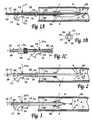
- FIG. 1Aschematically illustrates over-the-wire insertion of the balloon catheter of the invention
- FIG. 1Bshows a cross sectional side view of the balloon catheter of the invention
- FIG. 1Cschematically illustrates one embodiment of the syringe-like pressure-compensating device situated at the proximal end of the catheter system
- FIG. 2schematically illustrates the balloon catheter of the invention when inflated at a treatment site
- FIGS. 3 and 4schematically illustrate debris collection carried out by the balloon catheter of the invention by folding the inflated balloon and deflating it thereafter;
- FIG. 5is a flowchart demonstrating the steps of an interventional procedure performed with the balloon catheter of the invention that may involve sample collection;
- FIG. 6schematically illustrates the four balloon designs that were analyzed and compared in the finite element analysis study: a. Standard 20° tapering; b. 20° tapering with smooth round ending; c. Round ending; d. Round ending with initial retracting;
- FIG. 7graphically depicts the displacement vs. retracting force for the four balloon shapes, compared at an inflation pressure of 6 atmospheres.
- FIG. 8graphically depicts the maximum force generated in the catheter tubes following balloon folding, measured for different balloon inflation pressures
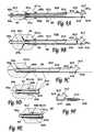
- FIGS. 9A to 9Cshow longitudinal section views of a rapid exchange catheter according to one preferred embodiment of the invention wherein the distal section of the inner tube comprise an internal slidable tube;
- FIGS. 9D and 9Edemonstrate utilizing different balloons for different manipulations thereof
- FIG. 9Fdemonstrates a piston-like construction for preventing pressure accumulation within the catheter during retraction
- FIG. 11shows a longitudinal section view of a rapid exchange catheter according to a third preferred embodiment of the invention wherein the distal section of the inner tube comprise an external slidable tube;
- FIG. 12shows a longitudinal section view of a rapid exchange catheter according to a fourth preferred embodiment of the invention wherein the diameter of the distal section of the inner tube is adapted to be received in an external slidable tube;
- FIG. 13shows a longitudinal section view of a rapid exchange catheter according to a fifth preferred embodiment of the invention wherein the distal section of the inner tube comprises a fixed inner tube on which an external slidable tube is mounted;
- FIGS. 14A to 14Cshow longitudinal section views of a rapid exchange catheter according to a sixth preferred embodiment of the invention wherein the inner tube of the catheter is encompassed in a slidable intermediate tube;
- FIGS. 15A to 15Cshow longitudinal section views of a rapid exchange catheter according to a seventh preferred embodiment of the invention comprising a movable inner tube affixed to a slidable sealing sleeve.
- the present inventionis directed to a method and apparatus for removing objects (such as atheromatous plaque debris) or collecting samples from a body passageway such as a blood vessel.
- the presently-disclosed method and apparatusmay also be used to expand a region of a body passageway (such as an atheromatous narrowing or occlusion of a blood vessel) in addition to removing debris or other matter or objects therefrom.
- a balloon catheterthat is suitable for carrying out common interventional procedures is adapted to enable the expansion of a region of a body passageway and collection of objects or samples from the treated site utilizing a unique design of catheter and balloon.
- balloon catheter 10comprises an inner tube 17 slidably positioned inside outer tube 18 .
- the proximal (i.e., trailing) end of inner tube 17comprises an entry port 12 , which extends outwardly through orifice 29 provided at the proximal end of outer tube 18 .
- Orifice 29tightly fits around the outer surface of inner tube 17 without gripping it, thereby allowing proximal and distal movements of inner tube 17 while sealing the inner lumen of outer tube 18 .
- Graduated scale 19may optionally be provided on the outer surface of inner tube 17 .
- the proximal end of outer tube 18further comprises a fluid port 11 for injecting/removing inflation fluids to/from inner lumen of outer tube 18 , an over-pressure valve outlet 15 for discharging inflation fluids whenever over-pressure conditions develop in the inner lumen of outer tube 18 , and an inner tube safety lock 14 adapted for gripping the outer surface of inner tube 17 , thereby preventing proximal-distal movements thereof relative to outer tube 18 .
- Over-pressure valve outlet 15may include an over-pressure valve 16 for sealing the opening of over-pressure valve outlet 15 and for discharging portions of inflating fluids therethrough whenever over-pressure conditions are reached in inner lumen of outer tube 18 .
- an inflatable member(not shown) may be attached to the opening of over-pressure valve outlet 15 , and in such an implementation over-pressure valve 16 may be eliminated.
- outer tube 18or portions thereof, may be inflatable such that over-pressure conditions may be resolved by its expansion.
- Inner tube safety lock 14contacts the outer surface of inner tube 17 via a tight orifice provided on the outer surface at the proximal end of outer tube 18 .
- a “U”-shaped gripping clip 24may be attached to inner tube safety lock 14 for gripping inner tube 17 therewith by pushing inner tube safety lock 14 inwardly and fitting the arms of gripping clip 24 around the outer surface of inner tube 17 .
- distal (leading) end of inner tube 17extends outwardly via the distal opening of outer tube 18 , into the body passage 20 .
- An inflatable memberfor example non-compliant balloon 5 , is attached to the distal ends of outer tube 18 and inner tube 17 .
- Balloon 5is preferably made from a flexible resilient sleeve having conical ends having gradually decreasing diameters towards the tips of the sleeve.
- Balloon 5is attached at circumferential attachment point 7 to the outer surface near the distal tip of outer tube 18 , and at circumferential attachment point 6 to the outer surface near the distal tip of inner tube 17 , such that it seals the distal opening of outer tube 18 .
- FIG. 1Ademonstrates over-the-wire insertion, wherein the insertion of balloon catheter 10 is performed over guide wire 13 . It should be clear, however, that the invention is not limited to one specific insertion method and that other appropriate and practicable insertion methods (e.g., using a guiding catheter) may also be used.
- step 51the operator inflates balloon 5 by injecting inflation fluids via fluid port 11 and the inner lumen of outer tube 18 , as demonstrated by fluid inflation arrows 8 a in FIG. 1A .
- inflation fluidsare preferably injected into balloon 5 such that its circumferential sides are expanded and pressed against the inner wall 21 of body passage 20 , as demonstrated in FIG. 2 .
- the pressure inside balloon 5 in such conditionsmay be in general about 1-25 Atmospheres, preferably about 6 Atmospheres.
- Step 52indicates the possibility of performing procedures if needed, however, some procedures (for example angioplasty) may be completed, or be near completion, once balloon 5 reaches its inflated state.
- step 53If it is determined in step 53 that a sample or other liquid or solid matter should be collected from the treatment site, for example fluids, secretions, and/or debris 25 , then in step 54 inner tube safety lock 14 is pulled thereby releasing its grip from inner tube 17 , as demonstrated by arrow 27 a in FIG. 2 .
- step 55the inner tube 17 is retracted outwardly (proximally) by the operator as shown by arrow 28 .
- the distal tip of balloon 5collapses and the outer surface portions are folded inwardly over the distal tip of inner tube 17 and thereafter over itself as further portions of the balloon collapse, as illustrated in FIG. 3 .
- the operatorcan determine via graduated scale 19 the amount of length of inner tube 17 that has been retracted and in this way determine when to stop the retraction and prevent further axial movement of inner tube 17 (step 58 ) by pushing down inner tube safety lock 14 , as indicated by arrow 27 b.
- step 56balloon 5 is deflated by retracting inflation fluids via fluid port 11 , as indicated by arrows 8 c in FIG. 4 .
- the pressure inside balloon 5 and inner lumen of outer tube 18is substantially decreased, and balloon 5 is deflated.
- the reduction in the volume of balloon 5results in the formation of an inner cavity 40 defined by the outer surface of the folded balloon section, as shown in FIG. 4 .
- step 57the operator retracts balloon catheter 10 proximally such that portion of fluid/secretion and debris 25 confined within inner cavity 40 are withdrawn with the balloon catheter 10 (not shown in the figures).
- the debris, objects or samples collectedmay be easily collected when the entire length of balloon catheter 10 is ejected from the body of the treated subject, by pushing the inner tube 17 distally and unfolding the folded portions of balloon 5 , thus restoring the deflated state of balloon 5 (shown in FIG. 1A ).
- the conduitsmay be constructed of a braided material or of materials having a defined molecular orientation.
- Inner tube 17is preferably made from a biocompatible polymer type of material, such as polyurethane or nylon or PET, and it may be manufactured utilizing conventional methods, such as extrusion.
- the diameter of inner lumen of inner tube 17is generally in the range of 0.2-2.0 mm, preferably about 0.5 mm, and its entire length is generally in the range of 100-2000 mm, preferably about 1500 mm.
- orifice 29 provided at the proximal tip of outer tube 18should be adapted to provide appropriate sealing of inner lumen of outer tube 18 it should also close over the outer surface of inner tube 17 such that inner tube 17 may be displaced therethrough with relatively low frictional forces. For example, if the diameter of inner tube 17 is 0.7 mm, then the diameter of orifice 29 should be 1.0 mm.
- Balloon 5is preferably a non-compliant or semi-compliant balloon such as manufactured by Advanced Polymers (Salem, USA) and by Interface Associates (CA). It may be manufactured utilizing conventional methods known in the balloon catheter industry from a non-compliance type of material such as Pebax or Nylon (preferably Nylon 12). Its length is generally in the range of 10-60 mm, preferably about 20 mm. The body diameter can vary from 2.0 mm to 5 mm for coronary artery applications, and be significantly larger for use in larger blood vessels. Preferably, the balloon should have a burst pressure within the range of 12-20 atmospheres.
- the proximal and distal edges of balloon 5are preferably adhered to the outer surfaces of outer tube 18 and inner tube 17 respectively, at circumferential attachment points 7 and 6 respectively, by utilizing a UV or thermobonding type of adhesive such as commonly used in the art.
- balloon 5has been found by the present inventors to be critical in order for said balloon to fulfill its intended functions in the presently-disclosed and claimed catheter system, namely:
- the materials and design of the balloonespecially the shape of the distal taper and the relationship between the distal and the proximal taper, thus allow the balloon to fold smoothly and with relatively low pulling forces. This also insures that the balloon will fold only its distal side.
- the balloonhas a proximal taper cone shaped with a 15-17 degree angle, and a 15 degree round cone distal taper, having a radius of about 0.5 mm at the junction of the taper and the neck.
- Inner tube safety lock 14is preferably made from a biocompatible polymer such as Tecoflex; its length is generally in the-range of 1-15 mm, preferably about 5 mm. If, for example, the cross-sectional diameter of inner tube safety lock 14 is about 2 mm, then the orifice provided on the outer surface of outer tube 18 through which inner tube safety lock 14 accesses inner lumen of outer tube 18 is preferably about 2.4 mm for providing suitable sealing of inner lumen of outer tube 18 .
- a biocompatible polymersuch as Tecoflex
- the present inventionaims to provide rapid exchange (RE) catheter implementations in which the length of a distal section of the catheter and the shape and/or volume of its distal balloon may be manipulated during procedures carried out therewith.
- RErapid exchange
- Such implementationsare ideally suited for use in debris collection applications, as described in connection with the OTW device of the present invention, hereinabove.
- the RE solutions of the present inventionmay also be used in any other RE application wherein it is necessary to alter the length of a distally-placed balloon element.
- the RE catheter of the inventioncomprises an outer catheter shaft and an inner tube provided therein, wherein the lumen of said inner tube may be accessed via a lateral port provided on the catheter's shaft.
- the inner tube of the catheteris affixed to the catheter's outer shaft and the catheter's length and its balloon are manipulated by a unique construction of the inner tube.
- the catheter's inner tubemay comprise a slidable distal tube that may be moved by the operator, distally or proximally relative to the catheter's outer shaft, via a displacement rod attached thereto.
- the inner tubemay be encompassed in a slidable intermediate tube which may be moved by the operator distally or proximally relative to the catheter's shaft.
- a unique catheter constructionis developed in order to provide a movable inner tube affixed to a slidable sealing sleeve which allows the operator to move the inner tube distally or proximally relative to the catheter's outer shaft and thereby manipulate its length and balloon.
- FIG. 9shows longitudinal section views of a first embodiment of the rapid exchange catheter 610 of the invention wherein the distal end of the catheter's inner tube 614 comprises a slidable internal tube 613 .
- Catheter 610comprises a hollow outer shaft 66 comprising inner tube 614 installed therein, and a slidable internal tube 613 placed in inner tube 614 such that it protrudes distally via a distal opening thereof.
- the inner lumens of inner tube 614 and slidable internal tube 613are linked, thereby providing a continuous inner lumen ending at a distal opening of slidable internal tube 613 .
- Proximal end of balloon 611 ais attached to hollow outer shaft 66 at proximal attachment points 62 b provided around the outer surface of a distal section thereof, and the distal end of said balloon is attached to the slidable internal tube 613 at distal attachment points 62 a provided around the outer surface of a distal section of said slidable internal tube.
- the lumen of inner tube 614may be accessed via a lateral port 612 provided on hollow outer shaft 66 , between a distal and proximal ends thereof.
- Guide wire 65(or other suitable accessories) may be inserted via lateral port 612 , advanced along the inner lumens of inner tube 614 and slidable internal tube 613 , and exit the inner lumen of slidable internal tube 613 through a distal opening thereof.
- Slidable concentric member 613is adapted to fit into inner tube 614 and its diameter is preferably smaller than the diameter of inner tube 614 such that it seals its distal opening while comfortably permitting distal or proximal sliding of slidable internal tube 613 therethrough.
- Distal end portion of displacement rod 618is attached to slidable internal tube 613 thereby allowing the operator to move slidable internal tube 613 distally or proximally relative to the catheter's outer shaft by pushing or pulling the proximal tip of displacement rod 618 .
- annular gasket 64attached to the surface of distal tip of inner tube 614 such that a distal portion thereof is pressed against an annular portion of the outer surface of slidable internal tube 613 .
- the proximal portion of hollow shaft 66comprises a fluid port 617 used for inflating or deflating balloon 611 a by an inflation fluid pressurized therethrough, an optional discharge valve 616 installed in discharge valve outlet 615 , and rod aperture 619 for moving displacement rod 618 distally or proximally therethrough.
- RE catheter 10is inserted into a body treatment site in which balloon 611 a may be inflated by an inflation fluid (designated by arrows 67 a in FIG. 9A ) pressurized through inflation fluid port 617 , for effecting dilation or other procedures in said treatment site and/or for anchoring said balloon therein.
- the pressurized fluidspass via the hollow interior of hollow shaft 66 and reach the interior of balloon 611 a via a distal opening thereof.
- FIG. 9Bthe hollow interior of hollow shaft 66 and the internal space of balloon 611 a are filled with pressurized inflation fluid.
- Distal opening of inner tube 614is sealed by slidable internal tube 613 and (optionally) by gasket 64 , thereby preventing leakage of pressurized inflation fluid thereinto.
- the pressure of the inflation fluid inside the systempresses the gasket and improves the sealing provided by gasket 64 .
- the gasket's grip on the outer surface of inner tube 614is diminished which makes it easier for the gasket to slide over it.
- the requisite procedureis typically carried out in the inflated state of the balloon.
- the operatormay manipulate the catheter length and the shape and volume of balloon 611 a by pulling displacement rod 618 b , thereby moving slidable internal tube 613 proximally further into inner tube 614 , as demonstrated by arrows 68 a .
- the distal end of balloon 611 acollapses and folds internally, as shown in FIG. 9C , which increases the pressure of the inflation fluid.
- a slender passage of discharge valveis expanded to allow portions of inflation fluid to exit via discharge valve outlet 615 and thereby reduce the pressure of inflation fluid below said threshold value.
- pressure discharge elements 615 and 616constitutes merely one possible means of pressure reduction.
- Hollow outer shaft 66is preferably made from a polymer or metal material, such as stainless steel (e.g. stainless steel 316), nitinol, or nylon, and it may be manufactured utilizing conventional methods, such as extrusion and laser cutting.
- the diameter of the hollow interior of hollow shaft 66is generally in the range of 1-2 mm (millimeters), preferably about 1.2 mm, and the diameter of inflation fluid port 617 is generally in the range of 2-6 mm, preferably about 3 mm.
- the diameter of discharge valve outlet 615is generally in the range of 2-6 mm, preferably about 3 mm, and the entire length of hollow shaft 66 is generally in the range of 500-2000 mm, preferably about 1400 mm.
- Inner tube 614is preferably made from a flexible polymer or metal material, such as pevax, nylon, stainless or nitinol and it may be manufactured utilizing conventional methods, such as extrusion and laser cutting.
- the diameter of inner lumen of inner tube 614is generally in the range of 0.3-1 mm, preferably about 0.8 mm, and its entire length is generally in the range of 100-300 mm, preferably about 120 mm.
- Slidable internal tube 613is preferably made from a flexible polymer or metal type of material, such as pevax, nylon, stainless or nitinol, and it may be manufactured utilizing conventional methods (e.g. extrusion).
- the diameter of inner lumen of slidable internal tube 613is generally in the range of 0.3-1 mm, preferably about 0.5 mm, and its entire length is generally in the range of 30-150 mm, preferably about 70 mm.
- Balloon 611 ais preferably a type of non-compliant or semi-compliant or low-compliant balloon such as manufactured by Interface Associates. It may be manufactured utilizing conventional methods known in the balloon catheter industry from a biocompatible polymer type of material such as nylon 12. Its length is generally in the range of 5-50 mm, preferably about 20 mm, and its diameter is generally in the range of 2 to 12 mm, preferably about 3 to 5 mm.
- proximal and distal edges of balloon 611 aare preferably adhered to the outer surfaces of hollow shaft 66 and slidable internal tube 613 , at circumferential attachment points 62 b and 62 a respectively, by utilizing a low profile type of adhesion such as thermo bonding, UV adhesives or acrylic manufactured by Locktight.
- Displacement rod 618may be manufactured from a metal wire or tube, such as Stainless steel, Nitinol (Nickel Titanium) and polymers, having a diameter generally in the range of 0.2-2 mm, preferably about 0.5 mm, and length generally in the range of 500-2000 mm, preferably about 1600 mm. Distal portion of displacement rod 618 may be adhered to the distal section of slidable internal tube 613 . Most preferably, distal portion of displacement rod 618 may be combined into the wall of internal tube 613 thereby enhancing its rigidity and the grip provided therewith.
- Rod aperture 619is adapted to allow conveniently moving displacement rod 618 therethrough while providing suitable sealing of the hollow interior of hollow shaft 66 , thereby preventing leakage of inflation fluid therefrom.
- the inflation fluidis preferably a saline or a saline mixed with radio-opaque solution in different ratios.
- a syringe pump, or other suitable inflation pumps, as commonly used in the field,may be used for introducing the inflation fluid into the system.
- the pressure in the system in its various statesis typically in the range of 1 to 25 atmospheres.
- discharge valve 616is preferably implemented by an annular element having an axial slender passage passing therein.
- discharge valve 616is manufactured from an elastomer type of material, such as PVC by an injection molding process. Its outer diameter is generally in the range of 2-6 mm, preferably about 4 mm, and its slender passage is designed to expand whenever a pressure gradient of about 4 atmospheres evolves between its ends.
- a proximal part 618 c of rod 618is made to be wide enough to occupy a volume of space within a proximal portion 66 b of hollow shaft 66 , as sown in FIG. 9F .
- This piston-like construction 618 callows for a syringe like action of rod 618 when retracted proximally, causing it to evacuate enough space in the proximal portion 66 b of the lumen of hollow shaft 66 . This extra space will then be filled by inflation fluid, thereby preventing pressure build-up within the catheter during retraction of the rod 618 .
- distal cavity 63 ais obtained by the inwardly folded distal sections of balloon 611 a .
- the volume encompassed by cavity 63 amay be enlarged by (partially or entirely) deflating the balloon in this folded state, thereby filling the enlarged cavity with samples and/or debris from the treatment site.
- Different distal balloonsmay be designed to provide various balloon manipulations as exemplified in FIGS. 9D and 9E .
- a proximal section of the ballooncollapses and folds inwardly in response to movement of slidable internal tube 613 proximally, thereby forming a proximal cavity 63 b .
- a balloon which has higher resistance to folding at its proximal tapered end relative to its distal tapered endThis can be achieved by using a balloon having different angles at its distal and proximal tapers, wherein a steeper taper facilitates its folding.
- balloon 611 ab shown in FIG. 9Dboth, proximal and distal, sections of the balloon are folded in response to movement of slidable internal tube 613 proximally, thereby forming a proximal cavity 63 b and a distal cavity 63 a .
- This resultmay be obtained for example by using a balloon 611 ab with a symmetric shape—namely, the balloon having the same taper at its distal and proximal sides.
- FIGS. 10A to 10Cshow longitudinal section views of a rapid exchange catheter 620 according to a second preferred embodiment of the invention wherein the diameter of a distal section 624 b of the inner tube 624 a is adapted to receive internal slidable tube 613 .
- the diameter of distal section 624 b of inner tube 624 ais made relatively greater than the diameter of the proximal section thereof.
- Internal slidable tube 613is designed to tightly fit into proximal section 624 b and thereby seal its distal opening and prevent leakage of inflation fluid thereinto.
- sealingmay be achieved by gasket 64 attached to the distal section 624 b of inner tube 624 a such that a distal portion thereof is pressed against an annular portion of the outer surface of slidable internal tube 613 .
- Internal slidable tube 613 and the proximal section of inner tube 624 amay be manufactured to have the same inner diameter, thereby forming a substantially homogenous inner lumen therebetween, particularly when internal slidable tube 613 is advanced all the way into distal section 624 b.
- balloon 611 amay be inflated by inflation fluid ( 67 a ) pressurized via inflation fluid port 617 , and catheter's 620 length and the shape and volume of balloon 611 a may be manipulated by moving displacement rod 618 distally or proximally, as exemplified in FIGS. 10A to 10C .
- Different balloonsmay be designed to provide various balloon folding configurations as exemplified in FIGS. 9D and 9E .
- Inner tube 624 amay be manufactured by an extrusion and laser cutting process from a plastomeric or metallic type of material, preferably from nylon, PET or stainless steel.
- the diameter of the distal section of inner tube 624 ais generally in the range of 0.3-2 mm, preferably about 0.5 mm, and the diameter of slidable internal tube 613 is adapted to provide tight fitting and the necessary sealing of distal opening of inner tube 624 a when said internal tube is inserted thereinside.
- FIG. 11shows a longitudinal section view of catheter 630 according to a third preferred embodiment of the invention wherein the distal section of the inner tube 614 comprises an external slidable tube 613 a .
- the distal end of balloon 611 ais attached to the slidable external tube 613 a at distal attachment points 62 a provided around the outer surface of a distal section of said slidable external tube.
- the diameter of external slidable tube 613 ais made relatively greater than the diameter of inner tube 614 .
- External slidable tube 613 ais designed to tightly fit over the outer surface of the proximal section of inner tube 614 and to thereby seal its distal opening and prevent leakage of inflation fluid thereinto.
- sealingmay be achieved by gasket 64 attached to the proximal end portion of external slidable tube 613 a such that a proximal portion thereof is pressed against an annular portion of the outer surface of inner tube 614 .
- External slidable tube 613 amay be manufactured by an extrusion and laser cutting process from a plastomeric or metallic type of material, preferably from nylon or stainless steel.
- the diameter of external slidable tube 613 ais adapted to provide tight fitting and the necessary sealing of distal opening of inner tube 614 when said external slidable tube is mounted thereover.
- the diameter of external slidable tube 613 amay be in the range of 0.3-2 mm, preferably about 0.8 mm.
- a fourth preferred embodiment ( 640 ) of the inventionis demonstrated in the longitudinal section view shown in FIG. 12 , wherein the diameter of the distal section 644 b of inner tube 644 a is adapted to be received in an external slidable tube 613 a .
- the distal end of balloon 611 ais attached to the slidable external tube 613 a at distal attachment points 62 a provided around the outer surface of a distal section of said slidable external tube.
- the diameter of distal section 644 b of inner tube 644 ais made relatively smaller than the diameter of the proximal section thereof.
- External slidable tube 613 ais designed to tightly fit over proximal section 644 b and thereby seal its distal opening and prevent leakage of inflation fluid thereinto.
- sealingmay be achieved by gasket 64 attached to the proximal end of External slidable tube 613 a such that a proximal portion thereof is pressed against an annular portion of the distal section 644 b of inner tube 644 a.
- the external slidable tube 613 a of catheter 640allows attachment of a relatively shorter displacement rod 618 a to the proximal section of said slidable tube 613 a .
- the distal portion of displacement rod 618 amay be combined into the wall of external slidable tube 613 a along its longitudinal length, thereby enhancing its rigidity and the grip provided therewith.
- Inner tube 644 amay be manufactured by an extrusion and laser cutting process from a plastomeric or metallic type of material, preferably from nylon or stainless steel.
- the diameter of the distal section 644 b of inner tube 644 ais generally in the range of 0.3-2 mm, preferably about 0.5 mm, and the diameter of external slidable tube 613 a is adapted to provide tight fitting and the necessary sealing of distal opening of inner tube 644 a when said external tube is mounted thereover.
- an external slidable tube 613 ais mounted over a inner tube 654 b protruding distally through a distal opening of fixed inner tube 654 a of catheter 650 .
- the distal end of balloon 611 ais attached to the slidable external tube 613 a at distal attachment points 62 a provided around the outer surface of a distal section of said slidable external tube.
- a proximal end portion of fixed inner tube 654 bis fitted into a distal opening of inner tube 654 a , such that it seals said distal opening and most of its longitudinal length protrudes distally therefrom into the hollow interior of hollow shaft 66 .
- the diameter of external slidable tube 613 ais adapted to tightly fit over the external surface of fixed inner tube 654 b , thereby sealing its distal opening while allowing it to be easily moved distally or proximally thereon by the operator.
- Sealant 64 cmay be applied to the proximal end of fixed inner tube 654 b in order to provide enhanced sealing of the distal opening of inner tube 654 a .
- Sealing of the distal opening of fixed inner tube 654 bmay be achieved by an annular gasket 64 attached to the proximal tip of external slidable tube 613 a such that a proximal portion thereof is pressed against an annular portion of the outer surface of fixed inner tube 654 b.
- Gaskets 64can be made of a flexible material such as silicone or polyurethane. Alternatively, gaskets 64 may be implemented by an added lubricant such as mineral oil or silicone oil which improves the sliding between the tubes. The sealing may be further increased by increasing the pressure in the balloon.
- tubes 613 a and 654 amay be fixed tubes such that tube 654 a is fixed to the shaft 663 and tube 613 a is fixed to the distal neck of balloon 611 a , such that tube 654 b can slide into both tubes.
- Fixed inner tube 654 a and external slidable tube 613 amay be manufactured by an extrusion and laser cutting process from a plastomeric or metallic type of material, preferably from nylon or flexible metal. Their diameters are adapted to provide tight fitting and the necessary sealing of distal openings of inner tube 654 a and of fixed inner tube 654 b.
- FIGS. 14A to 14Cshow longitudinal section views of a sixth preferred embodiment of the invention in which the inner tube 64 of catheter 660 is encompassed in a slidable intermediate tube 633 b .
- the distal end of balloon 611 ais attached to the slidable intermediate tube 633 b at distal attachment points 62 a provided around the outer surface of a distal section of said slidable intermediate tube.
- Horizontal opening 638is provided on an upper side of slidable intermediate tube 633 b .
- Tube 64protrudes upwardly through horizontal opening 638 towards the upper side of hollow shaft 66 at the location in which it is affixed thereto and provide an access to its lumen via lateral port 612 .
- balloon 611 amay be inflated by pressurized fluid (designated by arrows 67 a in FIG. 14A ) provided via inflation fluid port 617 .
- pressurized fluidpasses through the hollow interior of hollow shaft 663 into the internal space of balloon 611 a .
- the catheter and its balloon in the inflated stateare illustrated in FIG. 14B .
- the proximal section of intermediate tube 633 b between horizontal opening 638 and the proximal end of intermediate tube 633 bmay be sealed by a sealant 666 in order to prevent entry of inflation fluids thereinto.
- a portion of inflation fluidsare discharged via discharge valve 616 installed in discharge valve outlet 615 .
- proximal section of intermediate tube 633 bprotrudes proximally via proximal opening 665 provided at the proximal end of shaft 663 .
- Proximal opening 665is designed to conveniently allow the sliding of intermediate tube 633 b therethrough while providing suitable sealing thereof and preventing leakage of inflation fluid therefrom.
- Manipulation of the catheter's length and its balloon's shape and volumeare performed by sliding the intermediate tube 633 b proximally or distally relative to the catheter's shaft.
- the operatormay pull the proximal section of intermediate tube 633 b (designated by arrow 68 a in FIG. 14B ) thereby causing distal section of balloon 611 a to collapse and fold inwardly and deform cavity 63 a , as illustrated in FIG. 14C .
- Horizontal opening 638is adjusted to allow sliding intermediate tube 633 b proximally into a state in which attachment point 62 a reaches proximal end of shaft 663 , and on the other hand, to allow sliding intermediate tube 633 b sufficiently distally and enable stretching the full length of balloon 611 a.
- Intermediate tube 633 bmay be manufactured by extrusion or laser cutting processes, from a plastomer or metallic type of material such as nylon, Teflon, or flexible stainless steel.
- the diameters of inner tube 664 and of intermediate tube 633 bare adapted to allow insertion of inner tube into the lumen of intermediate tube 633 b while providing suitable sealing thereof and preventing leakage of inflation fluids thereinto.
- intermediate tube 633 bmay have an inner diameter of about 0.8 mm and the outer diameter of inner tube 664 may be of about 0.78 mm.
- Intermediate tube 633 bcan be manufactured by an extrusion process in which the ID (internal diameter) has an appropriate tolerance to fit over the outer diameter of inner tube 664 .
- Inner tube 664 and intermediate tube 633 bare assembled together such that lateral port 612 is located in the horizontal opening 638 of intermediate tube 633 b . Thereafter the tubes 664 and 633 b are inserted into the hollow shaft 663 and lateral port 612 can be attached to hollow shaft 663 .
- intermediate tube 633 bis not necessarily a complete tube. While the distal portion of intermediate tube 633 b should be of a tubular shape, its proximal portion may have other cross-sectional shapes such as a semilunar shape. Alternatively, proximal portion of intermediate tube 633 b may be implemented by a wire attached to its distal portion and exiting catheter 660 via proximal opening 665 .
- FIGS. 15A to 15Cshow longitudinal section views of a catheter 670 according to a seventh preferred embodiment of the invention wherein the inner tube 674 is made movable by affixing it to a slidable sealing sleeve 679 .
- the distal end of balloon 611 ais attached to the inner tube 674 at distal attachment points 62 a provided around the outer surface of a distal section of said inner tube.
- the inner tubeis disposed in the hollow interior of the catheter's hollow outer shaft 676 and a curved section 637 thereof comprising lateral port 612 protrudes outwardly therefrom.
- a lateral opening 69is provided on hollow outer shaft 676 from which said curved section 637 of inner tube 674 is protruding outwardly from hollow shaft 676 .
- Lateral opening 69is sealed by sealing sleeve 679 mounted over an outer surface of hollow outer shaft 676 . Sealing sleeve 679 is designed to tightly fit over the outer surface of hollow outer shaft 676 , and to seal lateral opening 69 and the attachment area between sealing sleeve 679 and the curved section 637 of inner tube 674 protruding therefrom.
- sealing sleeveis also made slidable to allow its movement distally or proximally within the limits imposed by lateral opening 69 .
- a movable inner tube 674is obtained.
- the operatormay inflate (designated by arrows 67 a in FIG. 15A ) balloon 611 a and move inner tube distally or proximally by sliding sealing sleeve 679 over hollow shaft 676 .
- a displacement rod 648may be employed for this purpose.
- Displacement rod 648may be attached to a proximal section of inner tube 674 and a proximal section thereof can be made available to the operator via a proximal opening 675 provided at the proximal end of hollow shaft 676 .
- Proximal opening 675is designed to allow conveniently sliding displacement rod 648 therethrough while providing suitable sealing thereof and preventing leakage of inflation fluid therefrom.
- Lateral opening 69is adjusted to allow moving inner tube 674 proximally into a state in which attachment point 62 a reaches the proximal end of hollow shaft 676 , and on the other hand, to allow moving inner tube 674 sufficiently distally and enable stretching balloon 611 a to its fullest length.
- Sealing sleeve 679can be manufactured by an extrusion and laser cutting process from a plastomer or metallic type of material, preferably from nylon or flexible stainless steel.
- the sealing and attachment of sealing sleeve 679 and the curved section 637 of inner tube 674is preferably obtained by bonding these parts together by thermo-bonding or any other adhesive method such that they can slide together.
- the diameter of sealing sleeve 679is adjusted according to the geometrical dimensions of hollow shaft 676 . For example, if the diameter of hollow shaft is about OD (outer diameter) 1.2 mm then the diameter of sealing sleeve is made about ID 1.22 mm.
- FIG. 15Cdemonstrates an implementation of catheter 670 a , similar to catheter 670 , wherein an inner sealing sleeve 677 is adapted to be installed in the hollow interior of hollow shaft 676 .
- inner sealing sleeve 677is adapted to be pressed against the inner wall of hollow shaft 676 about the area of lateral opening 69 and thereby to provide suitable sealing thereof.
- vertical section of inner tube 674protrudes outwardly via inner sealing sleeve 677 and may be accessed by the operator via lateral port 612 .
- the sealing and attachment of inner sealing sleeve 677 and vertical section of inner tube 674may be obtained using the same means described above with reference to catheter 670 .
- Inner sealing sleeve 677can be manufactured by an extrusion and laser cutting process from a plastomeric or metallic type of material, preferably from nylon or flexible stainless steel. The sealing and attachment of inner sealing sleeve 677 and the vertical section of inner tube 674 is preferably obtained in a similar manner as was explained hereinabove.
- the diameter of sealing sleeve 677is adjusted according to the geometrical dimensions of hollow shaft 676 . For example, if the diameter of hollow shaft is about ID 1 mm then the diameter of inner sealing sleeve is made about OD 0.98 mm.
- balloon catheter embodiments of the inventionwhich were described hereinabove may be implemented with different types of balloon enabling folding of the proximal section of the balloon, the distal section of the balloon, or both proximal and distal sections of the balloon, as was exemplified hereinabove with reference to FIGS. 9D and 9E .
- the balloon shape and force resistance characteristics of the catheter tubingare as described hereinabove in connection with the OTW systems, and exemplified in the following two Examples.
- FEAis a computerized tool which was used to optimize the balloon design in order to improve its ability to fold in the desired way.
- the FE modeldescribes an inflated balloon which its edge is retracted, resulting in folding of the balloon.
- the simulationwas performed on different balloon designs and at varied inflation pressures, taking into account the mechanical properties of the balloon material, which was chosen to be nylon 12 or pebax.
- FIG. 7shows the displacement vs. retracting force for the four balloon shapes at an inflation pressure of 6 atmospheres.
- the Tapered-Round Ending Balloonrequired the lowest force, whereas the Round Ending Balloons need the greatest force to collapse.
- the Tapered Ending Balloonis somewhere between them.
- the slope of the Tapered Ending Balloon in the initial phaseseems to be relatively moderate compared to the other balloon configurations. The moderate slope indicates higher stiffness. In other words, higher force is required to induce a given displacement.
- the slope of the Tapered-Round Ending Balloonis the steepest one, and suggests relatively high compliance to folding.
- the balloonwas inserted into a 3-mm glass tube, at straight position or inclined to 45°.
- a guidewirewas inserted into the inner tube in order to stabilize the folding motion.
- the balloonwas inflated using a compressor and the inflation pressure was controlled by a dispenser. The procedure was performed at pressures ranging between 3-7 atm, with increments of 1 atm.
- the balloonwas folded using the Hounsfield Test machine, by pulling the inner tube at speed of 100 mm/min up to 20 mm, and then pushing back at the same speed until the balloon was completely unfolded.
- the maximal force required for folding the balloon at each pressureis presented in FIG. 8
- the maximal forceincreases with the inflation pressure for both positions (straight and inclined) and ranges between 2-3.5 N (200-350 gr) with increments vary between 0.2-0.4 N (20-40 gr) per step of 1 atm in pressure.
- Higher inflation pressurerequires greater force to fold the balloon.
- the maximal forcesare slightly lower for the inclined position; however, repeated tests at the straight position revealed that the lesser forces result from the material fatigue. To support this assumption, visual examination of the balloon after 40 repeats showed that the balloon material lost its flexibility and looked crumpled.
Landscapes
- Health & Medical Sciences (AREA)
- Life Sciences & Earth Sciences (AREA)
- Heart & Thoracic Surgery (AREA)
- Biomedical Technology (AREA)
- Biophysics (AREA)
- Pulmonology (AREA)
- Engineering & Computer Science (AREA)
- Anesthesiology (AREA)
- Hematology (AREA)
- Animal Behavior & Ethology (AREA)
- General Health & Medical Sciences (AREA)
- Public Health (AREA)
- Veterinary Medicine (AREA)
- Child & Adolescent Psychology (AREA)
- Vascular Medicine (AREA)
- Media Introduction/Drainage Providing Device (AREA)
Abstract
Description
- a) inserting an OTW balloon catheter system as defined hereinabove over a guidewire into said internal passage, and advancing said catheter until the distal tip thereof has reached the site, at which it is desired to collect debris;
- b) inflating the balloon with expansion fluid;
- c) pulling the inner conduit of said balloon catheter in a proximal direction, such that the distal and/or proximal end(s) of said balloon intussuscept(s);
- d) deflating the balloon, thereby forming a cavity into which debris is collected and entrapped; and
- e) removing the balloon catheter from the internal passage of the subject, together with the entrapped debris.
- a) an outer conduit;
- b) an inner conduit, suitable for total or partial passage over a guide wire, wherein said inner conduit is disposed within the lumen of said outer conduit such that the longitudinal axes of said inner and outer conduits are substantially parallel, wherein said inner conduit is capable of being moved along its longitudinal axis in relation to said outer conduit and wherein the proximal end of said inner conduit is angled such that it pierces the wall of said outer conduit;
- c) means for permitting said axial movement of said inner conduit within said outer conduit, such that said movement is not hindered by the passage of the angled proximal part of the inner conduit through said outer conduit; and
- d) means, situated at the proximal end of the outer conduit, for causing axial pushing-pulling movements of said inner conduit.
- a) an outer conduit;
- b) an inner conduit, suitable for total or partial passage over a guide wire, wherein said inner conduit is disposed within the lumen of said outer conduit such that the longitudinal axes of said inner and outer conduits are substantially parallel, wherein said inner conduit is capable of being moved along its longitudinal axis in relation to said outer conduit, wherein the proximal end of said inner conduit is angled such that it pierces the wall of said outer conduit, and wherein the distal tip of said inner conduit extends beyond the distal tip of said outer conduit;
- c) an angioplastic balloon whose proximal margin is attached to the outer surface of the distal tip of said outer conduit, and whose distal margin is attached to the outer surface of the portion of the inner conduit that extends beyond the distal tip of said outer conduit, and wherein the distal and/or proximal end portion(s) of said balloon are capable of intussusception upon proximal movement of said inner conduit in relation to said outer conduit;
- d) means, situated at the proximal end of the outer conduit, for causing axial pushing-pulling movements of said inner conduit;
- e) means for the introduction of an expansion fluid into the annular space formed between the inner surface of the outer conduit and the outer surface of the inner conduit and therefrom into the lumen of said balloon, and for the removal thereof;
- f) means for preventing pressure changes within said annular space upon axial movement of said inner conduit in relation to said outer conduit; and
- g) means for permitting axial movement of said inner conduit within said outer conduit, such that said movement is not hindered by the passage of the angled proximal part of the inner conduit through said outer conduit.
- a) inserting a rapid exchange balloon catheter system as defined hereinabove into said internal passage, and advancing said catheter until the distal tip thereof has reached the site, at which it is desired to collect debris;
- b) inflating the balloon with expansion fluid;
- c) pulling the inner conduit of said balloon catheter in a proximal direction, such that the distal and/or proximal end(s) of said balloon intussuscept(s);
- d) deflating the balloon, thereby forming a cavity into which debris is collected and entrapped; and
- e) removing the balloon catheter from the internal passage of the subject, together with the entrapped debris.
- 2.5-4 mm balloons: the tubing should withstand up to 500 g; polymer tubing made of nylon or pevax reinforced during the manufacturing process can be used.
- 4-5 mm (or larger) balloons: the tubing should withstand forces up to 2 kg. In this case it will be necessary to use a braided tube (polymer tube with metal mesh reinforcement).
- i. to facilitate folding in such a way that the desired annular space is formed at the distal end of the intussuscepted balloon, by the application of the lowest possible retracting force;
- ii. to present a low profile that will facilitate introduction and withdrawal of the deflated balloon into and out of the catheter system and body passage.
- 1) Insertion of catheter into the body via peripheral blood vessel by use of standard rapid exchange method, as is well known in the art;
- 2) Inflation of the balloon by injecting inflation fluids via
fluid port 617 and the inner lumen ofouter shaft 66, as demonstrated byfluid inflation arrows 67ainFIG. 9A ; the pressure inside balloon611 may be in general about 1-25 Atmospheres, preferably about 6 Atmospheres. - 3) If required, a sample or other liquid or solid matter (for example fluids, secretions, and/or debris) may be collected from the treatment site. Firstly, the safety lock mechanism fitted to the proximal end of
proximal displacement rod 618 is pulled, thereby releasing its grip on said proximal displacement rod. (The safety lock is not shown inFIG. 9A ; a suitable type of safety mechanism is, however, depicted inFIG. 1B and described—in relation to the OTW device of the present invention—hereinabove.)Displacement rod 618 is then pulled proximally, thereby releasing retracting slidableinternal tube 613 proximally, as demonstrated byarrow 68ainFIG. 9B . During retraction of slidableinternal tube 613 by the operator the distal tip of balloon611 collapses and its outer surface portions are folded inwardly over the distal tip of slidableinternal tube 613 and thereafter over itself as further portions of the balloon collapse, as illustrated inFIG. 9C . - 4) Retraction of slidable
internal tube 613 and the resulting inward folding of balloon611 shortens the overall length of inflated balloon611 which actually reduces the volume of inflated balloon611. Consequently, the pressure exerted by the inflating fluids increases, resulting in a considerable pressure increase in balloon611 and inner lumen ofouter shaft 66. Whenever the pressure in balloon611 and inner lumen ofouter shaft 66 reaches a certain set-point inflation fluids can be discharged viadischarge valve 616, as shown byarrows 67binFIG. 9B , such that the pressure in balloon611 and inner lumen ofouter shaft 66 remains within a predetermined pressure range (e.g., 1-25 atmospheres). Another exemplary option for discharging pressure is by widening theproximal section 618cofrod 618 so it can act similar to a syringe action, as shown inFIG. 9F . During this step the operator can determine via graduated scale (not shown) provided onrod 618 the amount of length ofinner tube 614 that has been retracted and in this way determine when to stop the retraction ofinner tube 614. The aforementioned safety lock is then returned to its locked state, thereby preventing any further movement ofdisplacement rod 618 andinner tube 614. - 5) Subsequently, balloon611 is deflated by retracting inflation fluids via
fluid port 617. As a result, the pressure inside balloon611 and inner lumen ofouter tube 66 is substantially decreased, and balloon611 is deflated. The reduction in the volume of balloon611 results in enlargement ofdistal cavity 63a. - 6) The operator then retracts
balloon catheter 610 proximally such that portion of fluid/secretion and debris confined withinproximal cavity 63aare withdrawn with the balloon catheter610 (not shown in the figures). The debris, objects or samples collected may be easily collected when the entire length ofballoon catheter 610 is ejected from the body of the treated subject, by pushing theinner tube 614 distally and unfolding the folded portions of balloon611, thus restoring the deflated state of balloon611 (shown inFIG. 9A ).
- i. The balloon is made of a homogenous and isotropic material.
- ii. The balloon's shape is symmetrical around its longitudinal axis.
- iii. The balloon's shape is symmetrical around its mid transverse axis.
- iv. The folding results in flexural stresses in the balloon material. Thus the mechanical properties (Modulus and Poisson Ratio) of the substance when flexed are taken into account in the FE analyses.
Methods: - a) The analyses were performed using a nonlinear Finite Elements Analysis (FEA) program MSC.MARC. This software allows assessment of the structural integrity and performance of parts undergoing large deformations as a result of thermal or structural load (www.mscsoftware.com).
- b) The analyses were nonlinear, assuming large displacements and taking into account stiffness change due to geometry update and sequential forces.
- c) The model was 2D axisymmetric.
- d) The model consisted of about 1000 nodes and 1000 2D solid elements.
- e) Constant pressure was applied from within the balloon on its walls, reflecting the inflation pressure. Simultaneously, gradually increased axial force was exerted to the edge of the balloon, results in its folding. The displacement of the balloon wall in the horizontal (longitudinal) axis was measured versus the applied force.
- f) The longitudinal axis of the balloon was kept fixed, while the balloon walls were free to move/fold as a result of the axial load.
- g) The balloon's specifications are listed in the following table:
| Balloon Specifications |
| Balloon length [mm] | 20 | |
| Balloon Outer Diameter [mm] | 3 | |
| Tube Outer Diameter [mm] | 0.4 | |
| Balloon Body Wall Thickness [μm] | 10 | |
| Neck Wall Thickness [μm] | 50 | |
| Tube Wall Thickness [μm] | 100 | |
| Tapering | varying | |
| Material | PET (Polyethylene | |
| Terephthalate) |
| Mechanical Properties |
| Flexural Modulus [Kg/mm2] | 100 | ||
| Flexural Yield Strength | 8.15 | ||
| [Kg/mm2] | |||
| Poisson Ratio | 0.4 | ||
- h) Four balloon designs were analyzed, wherein the differences reside in the design of their tapering (see
FIG. 6 ):Standard 20° tapering- 20° tapering with smooth round ending
- Round ending
- Round ending with initial retracting
- i) The simulations were performed at five different inflation pressures: 1, 3, 6, 9 and 12 atmospheres.
Results:
- 3.0
mm Nylon 12 Vestamid L2101F Balloon (Interface Associates 316079-1) - Glass tube with inner diameter of 3 mm.
- Guidant HI-TORQUE CROSS-IT 200XT 0.014″ Guidewire.
- Hounsfield Test Equipment Model TX0927, 50-N load cell. This computer controlled testing machine enables determining tension, compression, shear, flexure and other mechanical and physical properties of materials. The machine provides selection of test speeds and direction of travel. It can measure the force and displacement values and can also graphically display the test.
- Assouline Compressor type 1.5 HP.
- Fluid dispensing system Model 1500XL.
Procedure:
Claims (22)
Priority Applications (12)
| Application Number | Priority Date | Filing Date | Title |
|---|---|---|---|
| US11/477,812US8556851B2 (en) | 2005-07-05 | 2006-06-30 | Balloon catheter |
| CN201310193577.4ACN103285498B (en) | 2005-10-14 | 2006-10-13 | Balloon catheter |
| US12/083,436US8894680B2 (en) | 2005-10-14 | 2006-10-13 | Balloon catheter |
| AU2006300813AAU2006300813A1 (en) | 2005-10-14 | 2006-10-13 | Balloon catheter |
| KR1020087010935AKR20090005283A (en) | 2005-10-14 | 2006-10-13 | Inflatable catheter |
| PCT/IB2006/002955WO2007042935A2 (en) | 2005-10-14 | 2006-10-13 | Balloon catheter |
| CA002625485ACA2625485A1 (en) | 2005-10-14 | 2006-10-13 | Balloon catheter |
| CN200680047235.XACN101553273B (en) | 2005-10-14 | 2006-10-13 | Balloon catheter |
| EP06809092.7AEP1948290A4 (en) | 2005-10-14 | 2006-10-13 | Balloon catheter |
| IL190829AIL190829A0 (en) | 2005-10-14 | 2008-04-13 | Balloon catheter |
| US14/012,624US9439662B2 (en) | 2005-07-05 | 2013-08-28 | Balloon catheter |
| US14/551,866US9782570B2 (en) | 2005-10-14 | 2014-11-24 | Balloon catheter |
Applications Claiming Priority (3)
| Application Number | Priority Date | Filing Date | Title |
|---|---|---|---|
| US69586805P | 2005-07-05 | 2005-07-05 | |
| US72616005P | 2005-10-14 | 2005-10-14 | |
| US11/477,812US8556851B2 (en) | 2005-07-05 | 2006-06-30 | Balloon catheter |
Related Child Applications (3)
| Application Number | Title | Priority Date | Filing Date |
|---|---|---|---|
| US12/083,436ContinuationUS8894680B2 (en) | 2005-10-14 | 2006-10-13 | Balloon catheter |
| PCT/IB2006/002955ContinuationWO2007042935A2 (en) | 2005-10-14 | 2006-10-13 | Balloon catheter |
| US14/012,624ContinuationUS9439662B2 (en) | 2005-07-05 | 2013-08-28 | Balloon catheter |
Publications (2)
| Publication Number | Publication Date |
|---|---|
| US20070083158A1 US20070083158A1 (en) | 2007-04-12 |
| US8556851B2true US8556851B2 (en) | 2013-10-15 |
Family
ID=37943179
Family Applications (3)
| Application Number | Title | Priority Date | Filing Date |
|---|---|---|---|
| US11/477,812Expired - Fee RelatedUS8556851B2 (en) | 2005-07-05 | 2006-06-30 | Balloon catheter |
| US12/083,436Expired - Fee RelatedUS8894680B2 (en) | 2005-10-14 | 2006-10-13 | Balloon catheter |
| US14/551,866Expired - Fee RelatedUS9782570B2 (en) | 2005-10-14 | 2014-11-24 | Balloon catheter |
Family Applications After (2)
| Application Number | Title | Priority Date | Filing Date |
|---|---|---|---|
| US12/083,436Expired - Fee RelatedUS8894680B2 (en) | 2005-10-14 | 2006-10-13 | Balloon catheter |
| US14/551,866Expired - Fee RelatedUS9782570B2 (en) | 2005-10-14 | 2014-11-24 | Balloon catheter |
Country Status (8)
| Country | Link |
|---|---|
| US (3) | US8556851B2 (en) |
| EP (1) | EP1948290A4 (en) |
| KR (1) | KR20090005283A (en) |
| CN (1) | CN103285498B (en) |
| AU (1) | AU2006300813A1 (en) |
| CA (1) | CA2625485A1 (en) |
| IL (1) | IL190829A0 (en) |
| WO (1) | WO2007042935A2 (en) |
Cited By (16)
| Publication number | Priority date | Publication date | Assignee | Title |
|---|---|---|---|---|
| US20120283514A1 (en)* | 2009-11-17 | 2012-11-08 | G.I. View Ltd. | Self-centralizing inflatable balloon |
| US20130046139A1 (en)* | 2011-08-19 | 2013-02-21 | Harold I. Daily | Hysteroscopes with curved tips |
| US9675780B2 (en) | 2010-01-19 | 2017-06-13 | Angioslide Ltd. | Balloon catheter system and methods of making and use thereof |
| US9782570B2 (en) | 2005-10-14 | 2017-10-10 | Angioslide Ltd. | Balloon catheter |
| US20180125510A1 (en)* | 2016-11-09 | 2018-05-10 | Cruzar Medsystems, Inc. | Systems and Methods for Traversing a Site of Obstruction |
| US10124153B2 (en) | 2012-12-04 | 2018-11-13 | Angioslide Ltd. | Balloon catheter and methods of use thereof |
| US10143814B2 (en) | 2011-03-29 | 2018-12-04 | Teleflex Life Sciences Unlimited Company | Fluid input module for multi-lumen catheters |
| US10322253B2 (en) | 2011-03-29 | 2019-06-18 | Teleflex Life Sciences Unlimited Company | Ballooned ventilation tube cleaning device |
| US10413703B2 (en) | 2012-12-31 | 2019-09-17 | Clearstream Technologies Limited | Catheter with markings to facilitate alignment |
| US10500360B1 (en) | 2014-08-29 | 2019-12-10 | Teleflex Life Sciences Unlimited Company | Catheter for cleaning of tracheal ventilation tubes |
| US10926009B2 (en) | 2016-01-06 | 2021-02-23 | Teleflex Life Sciences Pte. Ltd. | Closed suction system |
| US10946153B2 (en) | 2016-05-16 | 2021-03-16 | Teleflex Life Sciences Pte. Ltd. | Mechanical user control elements for fluid input module |
| US11452831B2 (en) | 2016-01-06 | 2022-09-27 | Airway Medix S.A. | Closed suction system |
| US11458286B2 (en) | 2014-03-31 | 2022-10-04 | Clearstream Technologies Limited | Catheter structures for reducing fluoroscopy usage during endovascular procedures |
| US11607234B2 (en) | 2019-06-11 | 2023-03-21 | Cruzar Medsystems, Inc. | Systems and methods for traversing a site of obstruction |
| US12402946B2 (en) | 2019-06-19 | 2025-09-02 | Boston Scientific Scimed, Inc. | Breakdown of laser pulse energy for breakup of vascular calcium |
Families Citing this family (63)
| Publication number | Priority date | Publication date | Assignee | Title |
|---|---|---|---|---|
| US7206509B2 (en)* | 2002-11-29 | 2007-04-17 | Lucent Technologies Inc. | Method and apparatus for temporally shifting one or more packets using wavelength selective delays |
| US9439662B2 (en) | 2005-07-05 | 2016-09-13 | Angioslide Ltd. | Balloon catheter |
| US20070088379A1 (en)* | 2005-10-17 | 2007-04-19 | Jacob Schneiderman | Minimally invasive a AAPT extirpation |
| EP2004268A4 (en)* | 2006-03-27 | 2009-12-23 | Tel Hashomer Medical Res Infrastructure & Services Ltd | INTRALUMINAL MASS COLLECTOR |
| JP2009542302A (en)* | 2006-07-06 | 2009-12-03 | アンジオスライド リミテッド | Collecting sheath and method of using the same |
| CA2703345C (en)* | 2007-10-22 | 2016-04-12 | Endocross Ltd. | Balloons and balloon catheter systems for treating vascular occlusions |
| US20090112252A1 (en)* | 2007-10-27 | 2009-04-30 | Salviac Limited | Catheter with removable filter retrieval tip |
| US8939991B2 (en) | 2008-06-08 | 2015-01-27 | Hotspur Technologies, Inc. | Apparatus and methods for removing obstructive material from body lumens |
| CN102131471A (en) | 2008-07-02 | 2011-07-20 | 安乔斯里德公司 | Balloon catheter system and methods of use thereof |
| US8945160B2 (en) | 2008-07-03 | 2015-02-03 | Hotspur Technologies, Inc. | Apparatus and methods for treating obstructions within body lumens |
| US9101382B2 (en) | 2009-02-18 | 2015-08-11 | Hotspur Technologies, Inc. | Apparatus and methods for treating obstructions within body lumens |
| US20100125324A1 (en)* | 2008-11-14 | 2010-05-20 | Medtronic Vascular, Inc. | Catheter Inner Member |
| WO2010079494A1 (en)* | 2009-01-12 | 2010-07-15 | Angioslide Ltd. | Balloon and catheter system and methods for making and use thereof |
| US20120109057A1 (en) | 2009-02-18 | 2012-05-03 | Hotspur Technologies, Inc. | Apparatus and methods for treating obstructions within body lumens |
| US9596979B2 (en)* | 2009-05-29 | 2017-03-21 | Smart Medical Systems Ltd. | Anchoring assemblies for endoscopes |
| WO2011036667A1 (en)* | 2009-09-23 | 2011-03-31 | Angioslide Ltd. | Balloon catheter and methods of use thereof |
| WO2011080731A1 (en)* | 2010-01-03 | 2011-07-07 | Angioslide Ltd. | Corrugated balloon catheter and methods of use thereof |
| US20130060234A1 (en)* | 2010-01-03 | 2013-03-07 | Doron Besser | Intussuscepting balloon catheter and methods for constructing and using thereof |
| CN105193371B (en) | 2010-03-09 | 2020-11-24 | 智能医疗系统有限公司 | Balloon endoscope and methods of making and using the same |
| US9795408B2 (en) | 2010-10-06 | 2017-10-24 | Cruzar Medsystems, Inc. | Catheter with vessel lining and methods for using same |
| US8926559B2 (en) | 2010-10-06 | 2015-01-06 | Cruzer Medsystems, Inc. | Catheter with vessel lining and methods for using same |
| EP3998099A1 (en) | 2011-03-07 | 2022-05-18 | Smart Medical Systems Ltd. | Balloon-equipped endoscopic devices and methods thereof |
| AU2012312066C1 (en) | 2011-09-22 | 2016-06-16 | 460Medical, Inc. | Systems and methods for visualizing ablated tissue |
| US9014789B2 (en) | 2011-09-22 | 2015-04-21 | The George Washington University | Systems and methods for visualizing ablated tissue |
| US20130190813A1 (en)* | 2012-01-24 | 2013-07-25 | St. Jude Medical Puerto Rico Llc | Balloon location device manifold for vascular closure device and methods |
| US20150105722A1 (en)* | 2012-03-09 | 2015-04-16 | Clearstream Technologies Limited | Balloon catheter with floating hub |
| US20140243843A1 (en)* | 2012-12-28 | 2014-08-28 | Cook Medical Technologies Llc | Rapid expansion balloon catheter |
| CN114951190A (en) | 2013-05-21 | 2022-08-30 | 智能医疗系统有限公司 | Endoscope reprocessing system and method |
| US20150073334A1 (en)* | 2013-09-10 | 2015-03-12 | Alexander Hetzel | Therapeutic device for administration of aerosol |
| WO2015069089A1 (en)* | 2013-11-11 | 2015-05-14 | 안용철 | Balloon catheter |
| JP6737705B2 (en) | 2013-11-14 | 2020-08-12 | ザ・ジョージ・ワシントン・ユニバーシティThe George Washingtonuniversity | Method of operating system for determining depth of injury site and system for generating images of heart tissue |
| JP2017500550A (en) | 2013-11-20 | 2017-01-05 | ザ・ジョージ・ワシントン・ユニバーシティThe George Washingtonuniversity | System and method for hyperspectral analysis of cardiac tissue |
| EP3753502B1 (en)* | 2014-02-06 | 2022-11-09 | Nipro Corporation | Catheter having cutter with torque shaft |
| US9855089B2 (en)* | 2014-03-21 | 2018-01-02 | Medtronic Cryocath Lp | Shape changing ablation balloon |
| CN103949006B (en)* | 2014-04-15 | 2016-08-17 | 上海市第六人民医院 | A kind of coronary dilatation catheter carrying ligustrazine nanoparticle |
| EP2962721B1 (en)* | 2014-07-04 | 2019-05-08 | Abiomed Europe GmbH | Sheath for sealed access to a vessel |
| US10661061B2 (en)* | 2014-09-08 | 2020-05-26 | Sanovas Intellectual Property, Llc | Clearance of sinus ostia blockage |
| US9351747B2 (en) | 2014-09-10 | 2016-05-31 | Vascular Solutions, Inc. | Capture assembly and method |
| EP3215001A4 (en) | 2014-11-03 | 2018-04-04 | Luxcath, LLC | Systems and methods for assessment of contact quality |
| KR102499045B1 (en) | 2014-11-03 | 2023-02-10 | 더 조지 워싱턴 유니버시티 | Systems and methods for lesion assessment |
| EP3223735A4 (en)* | 2014-11-25 | 2018-07-11 | Luxcath, LLC | Visualization catheters |
| AU2015369539B2 (en) | 2014-12-22 | 2020-06-25 | Smart Medical Systems Ltd. | Balloon endoscope reprocessing system and method |
| US10575855B2 (en)* | 2015-03-30 | 2020-03-03 | Boston Scientific Scimed, Inc. | Occlusion device |
| US10835107B2 (en) | 2015-04-03 | 2020-11-17 | Smart Medical Systems Ltd. | Endoscope electro-pneumatic adaptor |
| WO2016199117A1 (en)* | 2015-06-09 | 2016-12-15 | Angioslide Ltd | Improved balloon catheter and method of use |
| WO2017015163A1 (en)* | 2015-07-17 | 2017-01-26 | TriReme Medical, LLC | Balloon catheter with improved column strength and torque transmission |
| US10779904B2 (en) | 2015-07-19 | 2020-09-22 | 460Medical, Inc. | Systems and methods for lesion formation and assessment |
| CN105496506B (en)* | 2015-11-27 | 2018-09-14 | 中国人民解放军第二军医大学 | A kind of vascular repair conduit |
| WO2017200941A1 (en) | 2016-05-17 | 2017-11-23 | Talal Sharaiha LLC | Expandable intubation assemblies |
| CN108785826A (en)* | 2018-04-13 | 2018-11-13 | 中国人民解放军第四军医大学 | Reverse seal wire guide device |
| CN109893177B (en)* | 2019-04-24 | 2021-05-04 | 山东省立医院 | A device for bone marrow aspiration |
| US12280223B2 (en) | 2019-06-26 | 2025-04-22 | Boston Scientific Scimed, Inc. | Focusing element for plasma system to disrupt vascular lesions |
| US12274497B2 (en) | 2019-12-18 | 2025-04-15 | Bolt Medical, Inc. | Multiplexer for laser-driven intravascular lithotripsy device |
| EP4087511A4 (en) | 2020-01-08 | 2024-02-14 | 460Medical, Inc. | Systems and methods for optical interrogation of ablation lesions |
| KR102332076B1 (en)* | 2020-02-10 | 2021-11-26 | 계명대학교 산학협력단 | A brain catheter for optical coherent tomography for intra-cerebral vascular surgery and using method thereof |
| KR102329608B1 (en)* | 2020-04-07 | 2021-11-19 | 인제대학교 산학협력단 | Bended balloon catheter |
| US12295654B2 (en) | 2020-06-03 | 2025-05-13 | Boston Scientific Scimed, Inc. | System and method for maintaining balloon integrity within intravascular lithotripsy device with plasma generator |
| EP4277548B1 (en) | 2021-01-12 | 2025-06-04 | Bolt Medical, Inc. | Balloon assembly for valvuloplasty catheter system |
| CN112426615B (en)* | 2021-01-26 | 2021-04-16 | 北京泰杰伟业科技有限公司 | Catheter balloon |
| WO2022221370A1 (en)* | 2021-04-14 | 2022-10-20 | Cephea Valve Technologies, Inc. | Method and apparatus for collapsing a prosthetic heart valve |
| CN114618072B (en)* | 2022-02-15 | 2024-05-14 | 温州医科大学附属第二医院(温州医科大学附属育英儿童医院) | Operation tube for resetting intussusception air enema of children |
| WO2025016870A1 (en)* | 2023-07-14 | 2025-01-23 | Biotronik Ag | Catheter comprising a rolling membrane |
| WO2025080614A1 (en)* | 2023-10-10 | 2025-04-17 | Innocare Urologics, Llc | Balloon retention catheter or tube with distal safety valve |
Citations (80)
| Publication number | Priority date | Publication date | Assignee | Title |
|---|---|---|---|---|
| US4004588A (en)* | 1975-05-21 | 1977-01-25 | Wrightson Nma Limited | Apparatus for flushing ova from cows or mares |
| JPS5466582A (en) | 1977-11-04 | 1979-05-29 | Olympus Optical Co | Balloon catheter |
| US4243040A (en)* | 1979-09-17 | 1981-01-06 | Beecher William H | Extracting device for removing objects from human body passages |
| GB2054385A (en) | 1979-07-25 | 1981-02-18 | Fogarty T J | Dilatation catheter method and apparatus |
| WO1984001513A1 (en) | 1982-10-08 | 1984-04-26 | David Hardcastle | Balloon catheter and process for the manufacture thereof |
| US4469100A (en) | 1983-03-14 | 1984-09-04 | Hardwick Charles W | Intussuscepting balloon catheter for stone extraction |
| US4597389A (en) | 1982-09-30 | 1986-07-01 | Ibrahim Adel A | Device for removing objects from tubular body passages |
| US4611594A (en) | 1984-04-11 | 1986-09-16 | Northwestern University | Medical instrument for containment and removal of calculi |
| EP0200668A2 (en) | 1985-04-25 | 1986-11-05 | FOGARTY, Thomas J. | Apparatus and method for dislodging and removing occlusive objects from body passages |
| US4748982A (en) | 1987-01-06 | 1988-06-07 | Advanced Cardiovascular Systems, Inc. | Reinforced balloon dilatation catheter with slitted exchange sleeve and method |
| US4762129A (en) | 1984-11-23 | 1988-08-09 | Tassilo Bonzel | Dilatation catheter |
| EP0359489A2 (en) | 1988-09-15 | 1990-03-21 | Baxter International Inc. | Everting balloon catheter with anchor annulus and balloon for same |
| US4946440A (en) | 1988-10-05 | 1990-08-07 | Hall John E | Evertible membrane catheter and method of use |
| EP0380873A2 (en) | 1989-01-30 | 1990-08-08 | C.R. Bard, Inc. | Rapidly exchangeable coronary catheter |
| US4955895A (en) | 1986-12-23 | 1990-09-11 | Terumo Kabushiki Kaisha | Vasodilating catheter |
| US5019041A (en) | 1988-03-08 | 1991-05-28 | Scimed Life Systems, Inc. | Balloon catheter inflation device |
| US5092839A (en) | 1989-09-29 | 1992-03-03 | Kipperman Robert M | Coronary thrombectomy |
| US5109830A (en) | 1990-04-10 | 1992-05-05 | Candela Laser Corporation | Apparatus for navigation of body cavities |
| US5254091A (en) | 1991-01-08 | 1993-10-19 | Applied Medical Resources Corporation | Low profile balloon catheter and method for making same |
| US5307814A (en) | 1991-09-17 | 1994-05-03 | Medrad, Inc. | Externally moveable intracavity probe for MRI imaging and spectroscopy |
| USRE34633E (en) | 1987-11-13 | 1994-06-07 | Cook Incorporated | Balloon guide |
| US5338298A (en) | 1993-06-04 | 1994-08-16 | C. R. Bard, Inc. | Double-tapered balloon |
| US5437638A (en) | 1993-01-29 | 1995-08-01 | The United States Of America As Represented By The Secretary Of The Department Of Health And Human Services | Multifinger topocatheter tip for multilumen catheter for angioplasty and manipulation |
| US5470314A (en) | 1994-07-22 | 1995-11-28 | Walinsky; Paul | Perfusion balloon catheter with differential compliance |
| US5534007A (en) | 1995-05-18 | 1996-07-09 | Scimed Life Systems, Inc. | Stent deployment catheter with collapsible sheath |
| US5630822A (en) | 1993-07-02 | 1997-05-20 | General Surgical Innovations, Inc | Laparoscopic tissue removal device |
| WO1998029026A2 (en) | 1996-12-30 | 1998-07-09 | Imagyn Medical Technologies, Inc. | Expandable access device and method of constructing and using same |
| US5785675A (en) | 1990-08-06 | 1998-07-28 | Possis Medical, Inc. | Thrombectomy device |
| US5865801A (en)* | 1995-07-18 | 1999-02-02 | Houser; Russell A. | Multiple compartmented balloon catheter with external pressure sensing |
| US5868767A (en) | 1994-12-23 | 1999-02-09 | Devices For Vascular Intervention | Universal catheter with interchangeable work element |
| US5941895A (en) | 1996-09-04 | 1999-08-24 | Hemodynamics, Inc. | Cardiovascular stent and retrieval apparatus |
| US5968012A (en) | 1997-08-22 | 1999-10-19 | Scimed Lifesystems, Inc. | Balloon catheter with adjustable shaft |
| US6004341A (en) | 1996-12-05 | 1999-12-21 | Loma Linda University Medical Center | Vascular wound closure device |
| JP2000005189A (en) | 1998-06-24 | 2000-01-11 | Terumo Corp | Catheter for removing foreign matter |
| WO2000002613A1 (en) | 1998-07-09 | 2000-01-20 | Scimed Life Systems, Inc. | Method for reducing dilatation balloon cone stiffness |
| US6022359A (en) | 1999-01-13 | 2000-02-08 | Frantzen; John J. | Stent delivery system featuring a flexible balloon |
| US6039721A (en) | 1996-07-24 | 2000-03-21 | Cordis Corporation | Method and catheter system for delivering medication with an everting balloon catheter |
| EP0987045A2 (en) | 1998-09-16 | 2000-03-22 | Medtronic Ave, Inc. | Improved anchor joint for coaxial balloon dilatation catheter |
| WO2000027309A1 (en) | 1998-11-06 | 2000-05-18 | Scimed Life Systems, Inc. | Improved rolling membrane stent delivery system |
| WO2000038776A1 (en) | 1998-12-23 | 2000-07-06 | Scimed Life Systems, Inc. | Balloon catheter having an oscillating tip configuration |
| US6129706A (en) | 1998-12-10 | 2000-10-10 | Janacek; Jaroslav | Corrugated catheter balloon |
| US6152947A (en) | 1998-04-29 | 2000-11-28 | Embol-X, Inc. | Adjustable blood filtration system |
| EP1062966A1 (en) | 1999-06-25 | 2000-12-27 | Terumo Kabushiki Kaisha | Balloon for dilating a stricture and balloon catheter |
| US6179827B1 (en) | 1998-03-16 | 2001-01-30 | Chase Medical | Catheter having integral expandable/collapsible lumen |
| US6280412B1 (en) | 1999-06-17 | 2001-08-28 | Scimed Life Systems, Inc. | Stent securement by balloon modification |
| US6383195B1 (en) | 1998-04-13 | 2002-05-07 | Endoline, Inc. | Laparoscopic specimen removal apparatus |
| WO2002038084A2 (en) | 2000-11-10 | 2002-05-16 | Scimed Life Systems, Inc. | Improved rolling membrane stent delivery system |
| US20020082639A1 (en) | 1997-03-06 | 2002-06-27 | Scimed Life Systems, Inc. | Distal protection device and method |
| WO2002055146A1 (en) | 2001-01-09 | 2002-07-18 | Microvention, Inc. | Embolectomy catheters and method for treatment |
| US20020121472A1 (en) | 2001-03-01 | 2002-09-05 | Joseph Garner | Intravascular filter retrieval device having an actuatable dilator tip |
| US20020177870A1 (en) | 2001-05-25 | 2002-11-28 | Ivan Sepetka | Single lumen balloon catheter |
| US20030028211A1 (en) | 1994-02-24 | 2003-02-06 | Michael Crocker | Focalized stent implantation |
| US20030055483A1 (en) | 2001-08-23 | 2003-03-20 | Gumm Darrell C. | Rotating stent delivery system for side branch access and protection and method of using same |
| US20030093107A1 (en) | 2001-09-28 | 2003-05-15 | Edward Parsonage | Medical devices comprising nanocomposites |
| US20030105508A1 (en) | 2000-03-21 | 2003-06-05 | Johnson Kirk L. | Everting balloon stent delivery system having tapered leading edge |
| US20030130672A1 (en) | 2002-01-10 | 2003-07-10 | Scimed Life Systems, Inc. | Aspirating balloon catheter for treating vulnerable plaque |
| US20030176884A1 (en) | 2002-03-12 | 2003-09-18 | Marwane Berrada | Everted filter device |
| US20030208223A1 (en) | 2000-03-23 | 2003-11-06 | Kleiner Daniel Eduard | Device incorporating a hollow element for being positioned along a body cavity of a patient and method of positioning the same |
| WO2004014240A1 (en) | 2002-08-09 | 2004-02-19 | Velocimed, L.L.C. | Emboli protection devices and related methods of use |
| US6695810B2 (en) | 1997-11-21 | 2004-02-24 | Advanced Interventional Technologies, Inc. | Endolumenal aortic isolation assembly and method |
| US20040054362A1 (en) | 2002-09-16 | 2004-03-18 | Transurgical, Inc. | Balloon alignment and collapsing system |
| WO2004028611A1 (en) | 2002-09-26 | 2004-04-08 | Boston Scientific Limited | Medical device components and processes for their manufacturing |
| US20040073243A1 (en) | 2000-06-29 | 2004-04-15 | Concentric Medical, Inc., A Delaware Corporation | Systems, methods and devices for removing obstructions from a blood vessel |
| WO2004082462A2 (en) | 2003-03-17 | 2004-09-30 | Tyco Healthcare Group, Lp | Endoscopic tissue removal apparatus and method |
| WO2004098681A1 (en) | 2003-05-06 | 2004-11-18 | Asahi Intecc Co., Ltd. | Medical liquid-injecting device |
| US20040236367A1 (en) | 2003-05-22 | 2004-11-25 | Brian Brown | Tether equipped catheter |
| US20040236275A1 (en) | 2003-05-20 | 2004-11-25 | Pruitt Sean R. | Catheter having a light emitting component |
| WO2005000130A1 (en) | 2003-06-11 | 2005-01-06 | Concentric Medical, Inc. | Systems, methods and devices for removing obstructions from a blood vessel |
| US20050004553A1 (en) | 2003-07-02 | 2005-01-06 | Medtronic Ave, Inc. | Sheath catheter having variable over-the-wire length and methods of use |
| WO2005030308A1 (en) | 2003-09-22 | 2005-04-07 | Boston Scientific Limited | Microcatheter with sleeved guidewire port |
| US20050085826A1 (en) | 2003-10-21 | 2005-04-21 | Scimed Life Systems, Inc. | Unfolding balloon catheter for proximal embolus protection |
| US20050101986A1 (en) | 1997-03-06 | 2005-05-12 | Scimed Life Systems, Inc. | Distal protection device and method |
| US20050102019A1 (en) | 2003-11-12 | 2005-05-12 | Advanced Stent Technologies, Inc. | Catheter balloon systems and methods |
| US20050137607A1 (en) | 2003-10-23 | 2005-06-23 | Assell Robert L. | Bone dilator system |
| US20050154414A1 (en)* | 2004-01-13 | 2005-07-14 | Scimed Life Systems, Inc. | Catheter shaft having distal support |
| US20050187570A1 (en) | 2004-02-19 | 2005-08-25 | Applied Medical Resources Corporation | Embolectomy capture sheath |
| US20050209629A1 (en) | 2001-04-19 | 2005-09-22 | Kerr Sean H | Resorbable containment device and process for making and using same |
| US20050261705A1 (en) | 2004-05-21 | 2005-11-24 | Gist Christopher W | Device to remove kidney stones |
| US20060129107A1 (en) | 2004-11-29 | 2006-06-15 | Mcarthur Gregory R | Inflation syringe quick release apparatus |
| US7824345B2 (en)* | 2003-12-22 | 2010-11-02 | Boston Scientific Scimed, Inc. | Medical device with push force limiter |
Family Cites Families (46)
| Publication number | Priority date | Publication date | Assignee | Title |
|---|---|---|---|---|
| US4846174A (en) | 1986-08-08 | 1989-07-11 | Scimed Life Systems, Inc. | Angioplasty dilating guide wire |
| US4968300A (en) | 1988-10-05 | 1990-11-06 | Abiomed Limited Partnership | Balloon stretch mechanism |
| JPH02119875A (en) | 1988-10-28 | 1990-05-07 | Kanji Inoue | Balloon catheter and extending method for its balloon |
| DE68912713T2 (en) | 1988-10-28 | 1994-05-19 | Kanji Inoue | Balloon catheter. |
| US4994033A (en) | 1989-05-25 | 1991-02-19 | Schneider (Usa) Inc. | Intravascular drug delivery dilatation catheter |
| US5074845A (en) | 1989-07-18 | 1991-12-24 | Baxter International Inc. | Catheter with heat-fused balloon with waist |
| US5333298A (en)* | 1991-08-08 | 1994-07-26 | Honeywell Inc. | System for making data available to an outside software package by utilizing a data file which contains source and destination information |
| US5368566A (en) | 1992-04-29 | 1994-11-29 | Cardiovascular Dynamics, Inc. | Delivery and temporary stent catheter having a reinforced perfusion lumen |
| US5445646A (en) | 1993-10-22 | 1995-08-29 | Scimed Lifesystems, Inc. | Single layer hydraulic sheath stent delivery apparatus and method |
| JPH07136283A (en) | 1993-11-17 | 1995-05-30 | Terumo Corp | Expansion catheter |
| US5545132A (en) | 1993-12-21 | 1996-08-13 | C. R. Bard, Inc. | Helically grooved balloon for dilatation catheter and method of using |
| CA2183214A1 (en)* | 1994-02-09 | 1998-02-14 | Manouchehr Miraki | Balloon dilation catheter with hypotube |
| US7238197B2 (en) | 2000-05-30 | 2007-07-03 | Devax, Inc. | Endoprosthesis deployment system for treating vascular bifurcations |
| US5914895A (en)* | 1997-09-10 | 1999-06-22 | Cypress Semiconductor Corp. | Non-volatile random access memory and methods for making and configuring same |
| WO1999016499A1 (en) | 1997-10-01 | 1999-04-08 | Boston Scientific Corporation | Dilation systems and related methods |
| US5908435A (en) | 1997-10-23 | 1999-06-01 | Samuels; Shaun L. W. | Expandable lumen device and method of use |
| US6063057A (en) | 1998-06-01 | 2000-05-16 | Medtronic Ave, Inc. | Syringe apparatus adapted for use in catheterization procedures |
| US6613066B1 (en) | 1998-10-05 | 2003-09-02 | Kaneka Corporation | Balloon catheter and production method therefor |
| US6602263B1 (en) | 1999-11-30 | 2003-08-05 | St. Jude Medical Atg, Inc. | Medical grafting methods and apparatus |
| JP2003126263A (en) | 2001-10-22 | 2003-05-07 | Toray Ind Inc | Balloon catheter |
| US20050261719A1 (en)* | 2002-11-25 | 2005-11-24 | Israel Chermoni | Catheter and method of its use |
| IL161554A0 (en) | 2004-04-22 | 2004-09-27 | Gali Tech Ltd | Catheter |
| US20050267492A1 (en) | 2004-05-12 | 2005-12-01 | Philippe Poncet | Surgical instrument for specimen retrieval |
| US7972351B2 (en) | 2004-07-13 | 2011-07-05 | Boston Scientific Scimed, Inc. | Balloon folding design and method and apparatus for making balloons |
| US7565464B2 (en)* | 2004-12-14 | 2009-07-21 | Intel Corporation | Programmable transaction initiator architecture for systems with secure and non-secure modes |
| US8556851B2 (en) | 2005-07-05 | 2013-10-15 | Angioslide Ltd. | Balloon catheter |
| AU2006264397A1 (en) | 2005-07-05 | 2007-01-11 | Angioslide Ltd. | Balloon catheter |
| US8197505B2 (en) | 2005-10-14 | 2012-06-12 | Endocross Ltd. | Balloon catheter system for treating vascular occlusions |
| EP1942976B1 (en) | 2005-10-14 | 2011-06-29 | Endocross | Balloon catheter system for treating vascular occlusions |
| US20070088380A1 (en) | 2005-10-14 | 2007-04-19 | Endocross Ltd. | Balloon catheter system for treating vascular occlusions |
| US20070255305A1 (en) | 2006-04-28 | 2007-11-01 | Mcmichael Donald J | Percutaneous dilation apparatus |
| EP2181728B1 (en) | 2006-05-15 | 2012-06-27 | Endocross Ltd. | Balloon Catheter |
| CA2656814A1 (en) | 2006-07-06 | 2008-01-10 | Angioslide Ltd. | Collecting sheath and method of use thereof |
| JP2009542302A (en) | 2006-07-06 | 2009-12-03 | アンジオスライド リミテッド | Collecting sheath and method of using the same |
| CA2703345C (en) | 2007-10-22 | 2016-04-12 | Endocross Ltd. | Balloons and balloon catheter systems for treating vascular occlusions |
| US20090112239A1 (en) | 2007-10-31 | 2009-04-30 | Specialized Vascular Technologies, Inc. | Sticky dilatation balloon and methods of using |
| CN102131471A (en) | 2008-07-02 | 2011-07-20 | 安乔斯里德公司 | Balloon catheter system and methods of use thereof |
| WO2010001405A1 (en) | 2008-07-02 | 2010-01-07 | Angioslide Ltd. | Corrugated balloon catheter and methods of use thereof |
| US20100010303A1 (en) | 2008-07-09 | 2010-01-14 | Ethicon Endo-Surgery, Inc. | Inflatable access device |
| WO2010079494A1 (en) | 2009-01-12 | 2010-07-15 | Angioslide Ltd. | Balloon and catheter system and methods for making and use thereof |
| WO2011036667A1 (en) | 2009-09-23 | 2011-03-31 | Angioslide Ltd. | Balloon catheter and methods of use thereof |
| WO2011080731A1 (en) | 2010-01-03 | 2011-07-07 | Angioslide Ltd. | Corrugated balloon catheter and methods of use thereof |
| US20130060234A1 (en) | 2010-01-03 | 2013-03-07 | Doron Besser | Intussuscepting balloon catheter and methods for constructing and using thereof |
| US9675780B2 (en) | 2010-01-19 | 2017-06-13 | Angioslide Ltd. | Balloon catheter system and methods of making and use thereof |
| EP2928537A4 (en) | 2012-12-04 | 2016-08-03 | Angioslide Ltd | Balloon catheter and methods of use thereof |
| WO2016199117A1 (en) | 2015-06-09 | 2016-12-15 | Angioslide Ltd | Improved balloon catheter and method of use |
- 2006
- 2006-06-30USUS11/477,812patent/US8556851B2/ennot_activeExpired - Fee Related
- 2006-10-13WOPCT/IB2006/002955patent/WO2007042935A2/enactiveApplication Filing
- 2006-10-13CACA002625485Apatent/CA2625485A1/ennot_activeAbandoned
- 2006-10-13KRKR1020087010935Apatent/KR20090005283A/ennot_activeCeased
- 2006-10-13CNCN201310193577.4Apatent/CN103285498B/ennot_activeExpired - Fee Related
- 2006-10-13AUAU2006300813Apatent/AU2006300813A1/ennot_activeAbandoned
- 2006-10-13EPEP06809092.7Apatent/EP1948290A4/ennot_activeWithdrawn
- 2006-10-13USUS12/083,436patent/US8894680B2/ennot_activeExpired - Fee Related
- 2008
- 2008-04-13ILIL190829Apatent/IL190829A0/enunknown
- 2014
- 2014-11-24USUS14/551,866patent/US9782570B2/ennot_activeExpired - Fee Related
Patent Citations (86)
| Publication number | Priority date | Publication date | Assignee | Title |
|---|---|---|---|---|
| US4004588A (en)* | 1975-05-21 | 1977-01-25 | Wrightson Nma Limited | Apparatus for flushing ova from cows or mares |
| JPS5466582A (en) | 1977-11-04 | 1979-05-29 | Olympus Optical Co | Balloon catheter |
| US4271839A (en)* | 1979-07-25 | 1981-06-09 | Thomas J. Fogarty | Dilation catheter method and apparatus |
| GB2054385A (en) | 1979-07-25 | 1981-02-18 | Fogarty T J | Dilatation catheter method and apparatus |
| US4243040A (en)* | 1979-09-17 | 1981-01-06 | Beecher William H | Extracting device for removing objects from human body passages |
| US4597389A (en) | 1982-09-30 | 1986-07-01 | Ibrahim Adel A | Device for removing objects from tubular body passages |
| WO1984001513A1 (en) | 1982-10-08 | 1984-04-26 | David Hardcastle | Balloon catheter and process for the manufacture thereof |
| US4469100A (en) | 1983-03-14 | 1984-09-04 | Hardwick Charles W | Intussuscepting balloon catheter for stone extraction |
| US4611594A (en) | 1984-04-11 | 1986-09-16 | Northwestern University | Medical instrument for containment and removal of calculi |
| US4762129A (en) | 1984-11-23 | 1988-08-09 | Tassilo Bonzel | Dilatation catheter |
| US4762129B1 (en) | 1984-11-23 | 1991-07-02 | Tassilo Bonzel | |
| EP0200668A2 (en) | 1985-04-25 | 1986-11-05 | FOGARTY, Thomas J. | Apparatus and method for dislodging and removing occlusive objects from body passages |
| US4955895A (en) | 1986-12-23 | 1990-09-11 | Terumo Kabushiki Kaisha | Vasodilating catheter |
| US4748982A (en) | 1987-01-06 | 1988-06-07 | Advanced Cardiovascular Systems, Inc. | Reinforced balloon dilatation catheter with slitted exchange sleeve and method |
| USRE34633E (en) | 1987-11-13 | 1994-06-07 | Cook Incorporated | Balloon guide |
| US5019041A (en) | 1988-03-08 | 1991-05-28 | Scimed Life Systems, Inc. | Balloon catheter inflation device |
| EP0359489A2 (en) | 1988-09-15 | 1990-03-21 | Baxter International Inc. | Everting balloon catheter with anchor annulus and balloon for same |
| US4946440A (en) | 1988-10-05 | 1990-08-07 | Hall John E | Evertible membrane catheter and method of use |
| EP0380873A2 (en) | 1989-01-30 | 1990-08-08 | C.R. Bard, Inc. | Rapidly exchangeable coronary catheter |
| US5092839A (en) | 1989-09-29 | 1992-03-03 | Kipperman Robert M | Coronary thrombectomy |
| US5109830A (en) | 1990-04-10 | 1992-05-05 | Candela Laser Corporation | Apparatus for navigation of body cavities |
| US5785675A (en) | 1990-08-06 | 1998-07-28 | Possis Medical, Inc. | Thrombectomy device |
| US5254091A (en) | 1991-01-08 | 1993-10-19 | Applied Medical Resources Corporation | Low profile balloon catheter and method for making same |
| US5307814A (en) | 1991-09-17 | 1994-05-03 | Medrad, Inc. | Externally moveable intracavity probe for MRI imaging and spectroscopy |
| US5437638A (en) | 1993-01-29 | 1995-08-01 | The United States Of America As Represented By The Secretary Of The Department Of Health And Human Services | Multifinger topocatheter tip for multilumen catheter for angioplasty and manipulation |
| US5338298A (en) | 1993-06-04 | 1994-08-16 | C. R. Bard, Inc. | Double-tapered balloon |
| US5630822A (en) | 1993-07-02 | 1997-05-20 | General Surgical Innovations, Inc | Laparoscopic tissue removal device |
| US20030028211A1 (en) | 1994-02-24 | 2003-02-06 | Michael Crocker | Focalized stent implantation |
| US5470314A (en) | 1994-07-22 | 1995-11-28 | Walinsky; Paul | Perfusion balloon catheter with differential compliance |
| US5868767A (en) | 1994-12-23 | 1999-02-09 | Devices For Vascular Intervention | Universal catheter with interchangeable work element |
| US5534007A (en) | 1995-05-18 | 1996-07-09 | Scimed Life Systems, Inc. | Stent deployment catheter with collapsible sheath |
| US5865801A (en)* | 1995-07-18 | 1999-02-02 | Houser; Russell A. | Multiple compartmented balloon catheter with external pressure sensing |
| US6039721A (en) | 1996-07-24 | 2000-03-21 | Cordis Corporation | Method and catheter system for delivering medication with an everting balloon catheter |
| US5941895A (en) | 1996-09-04 | 1999-08-24 | Hemodynamics, Inc. | Cardiovascular stent and retrieval apparatus |
| US6004341A (en) | 1996-12-05 | 1999-12-21 | Loma Linda University Medical Center | Vascular wound closure device |
| WO1998029026A2 (en) | 1996-12-30 | 1998-07-09 | Imagyn Medical Technologies, Inc. | Expandable access device and method of constructing and using same |
| US20050101986A1 (en) | 1997-03-06 | 2005-05-12 | Scimed Life Systems, Inc. | Distal protection device and method |
| US20020082639A1 (en) | 1997-03-06 | 2002-06-27 | Scimed Life Systems, Inc. | Distal protection device and method |
| US5968012A (en) | 1997-08-22 | 1999-10-19 | Scimed Lifesystems, Inc. | Balloon catheter with adjustable shaft |
| US6695810B2 (en) | 1997-11-21 | 2004-02-24 | Advanced Interventional Technologies, Inc. | Endolumenal aortic isolation assembly and method |
| US6179827B1 (en) | 1998-03-16 | 2001-01-30 | Chase Medical | Catheter having integral expandable/collapsible lumen |
| US6383195B1 (en) | 1998-04-13 | 2002-05-07 | Endoline, Inc. | Laparoscopic specimen removal apparatus |
| US6152947A (en) | 1998-04-29 | 2000-11-28 | Embol-X, Inc. | Adjustable blood filtration system |
| JP2000005189A (en) | 1998-06-24 | 2000-01-11 | Terumo Corp | Catheter for removing foreign matter |
| WO2000002613A1 (en) | 1998-07-09 | 2000-01-20 | Scimed Life Systems, Inc. | Method for reducing dilatation balloon cone stiffness |
| EP0987045A2 (en) | 1998-09-16 | 2000-03-22 | Medtronic Ave, Inc. | Improved anchor joint for coaxial balloon dilatation catheter |
| US20030176910A1 (en) | 1998-11-06 | 2003-09-18 | Vrba Anthony C. | Rolling membrane stent delivery system |
| WO2000027309A1 (en) | 1998-11-06 | 2000-05-18 | Scimed Life Systems, Inc. | Improved rolling membrane stent delivery system |
| US6129706A (en) | 1998-12-10 | 2000-10-10 | Janacek; Jaroslav | Corrugated catheter balloon |
| WO2000038776A1 (en) | 1998-12-23 | 2000-07-06 | Scimed Life Systems, Inc. | Balloon catheter having an oscillating tip configuration |
| US6022359A (en) | 1999-01-13 | 2000-02-08 | Frantzen; John J. | Stent delivery system featuring a flexible balloon |
| US6280412B1 (en) | 1999-06-17 | 2001-08-28 | Scimed Life Systems, Inc. | Stent securement by balloon modification |
| EP1062966A1 (en) | 1999-06-25 | 2000-12-27 | Terumo Kabushiki Kaisha | Balloon for dilating a stricture and balloon catheter |
| US20030105508A1 (en) | 2000-03-21 | 2003-06-05 | Johnson Kirk L. | Everting balloon stent delivery system having tapered leading edge |
| US20030208223A1 (en) | 2000-03-23 | 2003-11-06 | Kleiner Daniel Eduard | Device incorporating a hollow element for being positioned along a body cavity of a patient and method of positioning the same |
| US20040073243A1 (en) | 2000-06-29 | 2004-04-15 | Concentric Medical, Inc., A Delaware Corporation | Systems, methods and devices for removing obstructions from a blood vessel |
| WO2002038084A2 (en) | 2000-11-10 | 2002-05-16 | Scimed Life Systems, Inc. | Improved rolling membrane stent delivery system |
| EP1333778A2 (en) | 2000-11-10 | 2003-08-13 | Boston Scientific Limited | Improved rolling membrane stent delivery system |
| WO2002055146A1 (en) | 2001-01-09 | 2002-07-18 | Microvention, Inc. | Embolectomy catheters and method for treatment |
| US20020121472A1 (en) | 2001-03-01 | 2002-09-05 | Joseph Garner | Intravascular filter retrieval device having an actuatable dilator tip |
| US20050209629A1 (en) | 2001-04-19 | 2005-09-22 | Kerr Sean H | Resorbable containment device and process for making and using same |
| US20020177870A1 (en) | 2001-05-25 | 2002-11-28 | Ivan Sepetka | Single lumen balloon catheter |
| US20030055483A1 (en) | 2001-08-23 | 2003-03-20 | Gumm Darrell C. | Rotating stent delivery system for side branch access and protection and method of using same |
| US20030093107A1 (en) | 2001-09-28 | 2003-05-15 | Edward Parsonage | Medical devices comprising nanocomposites |
| US20030130672A1 (en) | 2002-01-10 | 2003-07-10 | Scimed Life Systems, Inc. | Aspirating balloon catheter for treating vulnerable plaque |
| US20030176884A1 (en) | 2002-03-12 | 2003-09-18 | Marwane Berrada | Everted filter device |
| WO2004014240A1 (en) | 2002-08-09 | 2004-02-19 | Velocimed, L.L.C. | Emboli protection devices and related methods of use |
| US20040054362A1 (en) | 2002-09-16 | 2004-03-18 | Transurgical, Inc. | Balloon alignment and collapsing system |
| WO2004028611A1 (en) | 2002-09-26 | 2004-04-08 | Boston Scientific Limited | Medical device components and processes for their manufacturing |
| WO2004082462A2 (en) | 2003-03-17 | 2004-09-30 | Tyco Healthcare Group, Lp | Endoscopic tissue removal apparatus and method |
| WO2004098681A1 (en) | 2003-05-06 | 2004-11-18 | Asahi Intecc Co., Ltd. | Medical liquid-injecting device |
| US20060025720A1 (en) | 2003-05-06 | 2006-02-02 | Asahi Intecc Co., Ltd. | Medicinal-liquid injection apparatus |
| US20040236275A1 (en) | 2003-05-20 | 2004-11-25 | Pruitt Sean R. | Catheter having a light emitting component |
| US20040236367A1 (en) | 2003-05-22 | 2004-11-25 | Brian Brown | Tether equipped catheter |
| WO2005000130A1 (en) | 2003-06-11 | 2005-01-06 | Concentric Medical, Inc. | Systems, methods and devices for removing obstructions from a blood vessel |
| US20050004553A1 (en) | 2003-07-02 | 2005-01-06 | Medtronic Ave, Inc. | Sheath catheter having variable over-the-wire length and methods of use |
| WO2005030308A1 (en) | 2003-09-22 | 2005-04-07 | Boston Scientific Limited | Microcatheter with sleeved guidewire port |
| US20050085826A1 (en) | 2003-10-21 | 2005-04-21 | Scimed Life Systems, Inc. | Unfolding balloon catheter for proximal embolus protection |
| WO2005041788A1 (en) | 2003-10-21 | 2005-05-12 | Boston Scientific Limited | Unfolding balloon catheter for proximal embolus protection |
| US20050137607A1 (en) | 2003-10-23 | 2005-06-23 | Assell Robert L. | Bone dilator system |
| US20050102019A1 (en) | 2003-11-12 | 2005-05-12 | Advanced Stent Technologies, Inc. | Catheter balloon systems and methods |
| US7824345B2 (en)* | 2003-12-22 | 2010-11-02 | Boston Scientific Scimed, Inc. | Medical device with push force limiter |
| US20050154414A1 (en)* | 2004-01-13 | 2005-07-14 | Scimed Life Systems, Inc. | Catheter shaft having distal support |
| US20050187570A1 (en) | 2004-02-19 | 2005-08-25 | Applied Medical Resources Corporation | Embolectomy capture sheath |
| US20050261705A1 (en) | 2004-05-21 | 2005-11-24 | Gist Christopher W | Device to remove kidney stones |
| US20060129107A1 (en) | 2004-11-29 | 2006-06-15 | Mcarthur Gregory R | Inflation syringe quick release apparatus |
Cited By (21)
| Publication number | Priority date | Publication date | Assignee | Title |
|---|---|---|---|---|
| US9782570B2 (en) | 2005-10-14 | 2017-10-10 | Angioslide Ltd. | Balloon catheter |
| US20120283514A1 (en)* | 2009-11-17 | 2012-11-08 | G.I. View Ltd. | Self-centralizing inflatable balloon |
| US8939895B2 (en)* | 2009-11-17 | 2015-01-27 | G. I. View Ltd. | Self-centralizing inflatable balloon |
| US9675780B2 (en) | 2010-01-19 | 2017-06-13 | Angioslide Ltd. | Balloon catheter system and methods of making and use thereof |
| US10322253B2 (en) | 2011-03-29 | 2019-06-18 | Teleflex Life Sciences Unlimited Company | Ballooned ventilation tube cleaning device |
| US10143814B2 (en) | 2011-03-29 | 2018-12-04 | Teleflex Life Sciences Unlimited Company | Fluid input module for multi-lumen catheters |
| US10328224B2 (en) | 2011-03-29 | 2019-06-25 | Teleflex Life Sciences Unlimited Company | Mechanical user control of fluid input module |
| US10806884B2 (en) | 2011-03-29 | 2020-10-20 | Teleflex Life Sciences Pte. Ltd. | Ballooned ventilation tube cleaning device |
| US20130046139A1 (en)* | 2011-08-19 | 2013-02-21 | Harold I. Daily | Hysteroscopes with curved tips |
| US11291351B2 (en)* | 2011-08-19 | 2022-04-05 | Harold I. Daily | Hysteroscopes with curved tips |
| US10124153B2 (en) | 2012-12-04 | 2018-11-13 | Angioslide Ltd. | Balloon catheter and methods of use thereof |
| US10413703B2 (en) | 2012-12-31 | 2019-09-17 | Clearstream Technologies Limited | Catheter with markings to facilitate alignment |
| US11458286B2 (en) | 2014-03-31 | 2022-10-04 | Clearstream Technologies Limited | Catheter structures for reducing fluoroscopy usage during endovascular procedures |
| US10500360B1 (en) | 2014-08-29 | 2019-12-10 | Teleflex Life Sciences Unlimited Company | Catheter for cleaning of tracheal ventilation tubes |
| US11452831B2 (en) | 2016-01-06 | 2022-09-27 | Airway Medix S.A. | Closed suction system |
| US10926009B2 (en) | 2016-01-06 | 2021-02-23 | Teleflex Life Sciences Pte. Ltd. | Closed suction system |
| US10946153B2 (en) | 2016-05-16 | 2021-03-16 | Teleflex Life Sciences Pte. Ltd. | Mechanical user control elements for fluid input module |
| US20180125510A1 (en)* | 2016-11-09 | 2018-05-10 | Cruzar Medsystems, Inc. | Systems and Methods for Traversing a Site of Obstruction |
| US10349957B2 (en)* | 2016-11-09 | 2019-07-16 | Cruzar Medsystems, Inc. | Systems and methods for traversing a site of obstruction |
| US11607234B2 (en) | 2019-06-11 | 2023-03-21 | Cruzar Medsystems, Inc. | Systems and methods for traversing a site of obstruction |
| US12402946B2 (en) | 2019-06-19 | 2025-09-02 | Boston Scientific Scimed, Inc. | Breakdown of laser pulse energy for breakup of vascular calcium |
Also Published As
| Publication number | Publication date |
|---|---|
| US9782570B2 (en) | 2017-10-10 |
| WO2007042935A2 (en) | 2007-04-19 |
| EP1948290A2 (en) | 2008-07-30 |
| US8894680B2 (en) | 2014-11-25 |
| US20150126966A1 (en) | 2015-05-07 |
| US20070083158A1 (en) | 2007-04-12 |
| EP1948290A4 (en) | 2013-12-11 |
| IL190829A0 (en) | 2008-12-29 |
| CA2625485A1 (en) | 2007-04-19 |
| KR20090005283A (en) | 2009-01-13 |
| US20090204069A1 (en) | 2009-08-13 |
| AU2006300813A1 (en) | 2007-04-19 |
| CN103285498A (en) | 2013-09-11 |
| CN103285498B (en) | 2015-11-25 |
| WO2007042935A3 (en) | 2009-04-16 |
Similar Documents
| Publication | Publication Date | Title |
|---|---|---|
| US8556851B2 (en) | Balloon catheter | |
| EP1904139B1 (en) | Balloon catheter | |
| EP2236168B1 (en) | Balloon catheter system and method of constructing such system | |
| US9439662B2 (en) | Balloon catheter | |
| US8827951B2 (en) | Balloon catheter system and methods of use thereof | |
| US20130060234A1 (en) | Intussuscepting balloon catheter and methods for constructing and using thereof | |
| CN101257943B (en) | balloon catheter | |
| WO2011080731A1 (en) | Corrugated balloon catheter and methods of use thereof | |
| EP3212273B1 (en) | Elastic tip for an adjustable length angioplasty balloon sheath | |
| IL188567A (en) | Balloon catheter | |
| HK1244721A1 (en) | Elastic tip for an adjustable length angioplasty balloon sheath | |
| HK1244721B (en) | Elastic tip for an adjustable length angioplasty balloon sheath |
Legal Events
| Date | Code | Title | Description |
|---|---|---|---|
| AS | Assignment | Owner name:ANGIOSLIDE LTD., ISRAEL Free format text:ASSIGNMENT OF ASSIGNORS INTEREST;ASSIGNORS:HIRSZOWICZ, ERAN;DUBI, SHAY;SIGNING DATES FROM 20060920 TO 20060921;REEL/FRAME:018455/0192 Owner name:ANGIOSLIDE LTD., ISRAEL Free format text:ASSIGNMENT OF ASSIGNORS INTEREST;ASSIGNORS:HIRSZOWICZ, ERAN;DUBI, SHAY;REEL/FRAME:018455/0192;SIGNING DATES FROM 20060920 TO 20060921 | |
| AS | Assignment | Owner name:PLENUS MANAGEMENT (2004) LTD., ISRAEL Free format text:SECURITY AGREEMENT;ASSIGNOR:ANGIOSLIDE LTD.;REEL/FRAME:023229/0418 Effective date:20090813 Owner name:PLENUS MANAGEMENT III 2007 LTD., ISRAEL Free format text:SECURITY AGREEMENT;ASSIGNOR:ANGIOSLIDE LTD.;REEL/FRAME:023229/0418 Effective date:20090813 Owner name:PLENUS MANAGEMENT (2004) LTD.,ISRAEL Free format text:SECURITY AGREEMENT;ASSIGNOR:ANGIOSLIDE LTD.;REEL/FRAME:023229/0418 Effective date:20090813 Owner name:PLENUS MANAGEMENT III 2007 LTD.,ISRAEL Free format text:SECURITY AGREEMENT;ASSIGNOR:ANGIOSLIDE LTD.;REEL/FRAME:023229/0418 Effective date:20090813 | |
| AS | Assignment | Owner name:PLENUS MANAGEMENT III 2007 LTD., ISRAEL Free format text:AMENDMENT TO SECURITY AGREEMENT DATED 08-13-2009;ASSIGNOR:ANGIOSLIDE LTD.;REEL/FRAME:025139/0755 Effective date:20101014 Owner name:PLENUS MANAGEMENT (2004) LTD., ISRAEL Free format text:AMENDMENT TO SECURITY AGREEMENT DATED 08-13-2009;ASSIGNOR:ANGIOSLIDE LTD.;REEL/FRAME:025139/0755 Effective date:20101014 | |
| STCF | Information on status: patent grant | Free format text:PATENTED CASE | |
| FPAY | Fee payment | Year of fee payment:4 | |
| FEPP | Fee payment procedure | Free format text:ENTITY STATUS SET TO SMALL (ORIGINAL EVENT CODE: SMAL) | |
| FEPP | Fee payment procedure | Free format text:MAINTENANCE FEE REMINDER MAILED (ORIGINAL EVENT CODE: REM.); ENTITY STATUS OF PATENT OWNER: SMALL ENTITY | |
| LAPS | Lapse for failure to pay maintenance fees | Free format text:PATENT EXPIRED FOR FAILURE TO PAY MAINTENANCE FEES (ORIGINAL EVENT CODE: EXP.); ENTITY STATUS OF PATENT OWNER: SMALL ENTITY | |
| STCH | Information on status: patent discontinuation | Free format text:PATENT EXPIRED DUE TO NONPAYMENT OF MAINTENANCE FEES UNDER 37 CFR 1.362 | |
| FP | Lapsed due to failure to pay maintenance fee | Effective date:20211015 |