US8554374B2 - Thermostat with electronic image display - Google Patents
Thermostat with electronic image displayDownload PDFInfo
- Publication number
- US8554374B2 US8554374B2US11/840,290US84029007AUS8554374B2US 8554374 B2US8554374 B2US 8554374B2US 84029007 AUS84029007 AUS 84029007AUS 8554374 B2US8554374 B2US 8554374B2
- Authority
- US
- United States
- Prior art keywords
- display
- thermostat
- controller
- image
- controller unit
- Prior art date
- Legal status (The legal status is an assumption and is not a legal conclusion. Google has not performed a legal analysis and makes no representation as to the accuracy of the status listed.)
- Expired - Lifetime, expires
Links
Images


Classifications
- G—PHYSICS
- G05—CONTROLLING; REGULATING
- G05B—CONTROL OR REGULATING SYSTEMS IN GENERAL; FUNCTIONAL ELEMENTS OF SUCH SYSTEMS; MONITORING OR TESTING ARRANGEMENTS FOR SUCH SYSTEMS OR ELEMENTS
- G05B19/00—Programme-control systems
- G05B19/02—Programme-control systems electric
- G05B19/04—Programme control other than numerical control, i.e. in sequence controllers or logic controllers
- G05B19/042—Programme control other than numerical control, i.e. in sequence controllers or logic controllers using digital processors
- G05B19/0423—Input/output
- F—MECHANICAL ENGINEERING; LIGHTING; HEATING; WEAPONS; BLASTING
- F24—HEATING; RANGES; VENTILATING
- F24F—AIR-CONDITIONING; AIR-HUMIDIFICATION; VENTILATION; USE OF AIR CURRENTS FOR SCREENING
- F24F11/00—Control or safety arrangements
- F24F11/30—Control or safety arrangements for purposes related to the operation of the system, e.g. for safety or monitoring
- F—MECHANICAL ENGINEERING; LIGHTING; HEATING; WEAPONS; BLASTING
- F24—HEATING; RANGES; VENTILATING
- F24F—AIR-CONDITIONING; AIR-HUMIDIFICATION; VENTILATION; USE OF AIR CURRENTS FOR SCREENING
- F24F11/00—Control or safety arrangements
- F24F11/62—Control or safety arrangements characterised by the type of control or by internal processing, e.g. using fuzzy logic, adaptive control or estimation of values
- F24F11/63—Electronic processing
- G—PHYSICS
- G05—CONTROLLING; REGULATING
- G05D—SYSTEMS FOR CONTROLLING OR REGULATING NON-ELECTRIC VARIABLES
- G05D23/00—Control of temperature
- G05D23/19—Control of temperature characterised by the use of electric means
- G05D23/1902—Control of temperature characterised by the use of electric means characterised by the use of a variable reference value
- G—PHYSICS
- G06—COMPUTING OR CALCULATING; COUNTING
- G06F—ELECTRIC DIGITAL DATA PROCESSING
- G06F3/00—Input arrangements for transferring data to be processed into a form capable of being handled by the computer; Output arrangements for transferring data from processing unit to output unit, e.g. interface arrangements
- G06F3/01—Input arrangements or combined input and output arrangements for interaction between user and computer
- G06F3/048—Interaction techniques based on graphical user interfaces [GUI]
- G06F3/0484—Interaction techniques based on graphical user interfaces [GUI] for the control of specific functions or operations, e.g. selecting or manipulating an object, an image or a displayed text element, setting a parameter value or selecting a range
- G06F3/04842—Selection of displayed objects or displayed text elements
- G—PHYSICS
- G06—COMPUTING OR CALCULATING; COUNTING
- G06F—ELECTRIC DIGITAL DATA PROCESSING
- G06F3/00—Input arrangements for transferring data to be processed into a form capable of being handled by the computer; Output arrangements for transferring data from processing unit to output unit, e.g. interface arrangements
- G06F3/01—Input arrangements or combined input and output arrangements for interaction between user and computer
- G06F3/048—Interaction techniques based on graphical user interfaces [GUI]
- G06F3/0484—Interaction techniques based on graphical user interfaces [GUI] for the control of specific functions or operations, e.g. selecting or manipulating an object, an image or a displayed text element, setting a parameter value or selecting a range
- G06F3/04847—Interaction techniques to control parameter settings, e.g. interaction with sliders or dials
Definitions
- the present inventionrelates generally to the field of programmable controllers for homes and/or buildings and their related grounds. More specifically, the present invention relates to such controllers with a display, and an I/O interface for uploading electronic images and/or other information for use by the controller and/or for viewing on the display of the controller.
- Controllersare used on a wide variety of devices and systems for controlling various functions in homes and/or buildings and their related grounds. Some controllers have schedule programming that modifies device parameters such as set points as a function of date and/or time. Some such device or system controllers that utilize schedule programming for controlling various functions in homes and/or buildings and their related grounds include, for example, HVAC controllers such as thermostats, water heater controllers, water softener controllers, security system controllers, lawn sprinkler controllers, and lighting system controllers.
- HVAC controllerssuch as thermostats, water heater controllers, water softener controllers, security system controllers, lawn sprinkler controllers, and lighting system controllers.
- controllerscan be employed to monitor and, if necessary, control various environmental conditions occurring within a structure.
- the controllermay include a microprocessor and/or microcontroller that interacts with other components in the system via an I/O interface to regulate the temperature, humidity, venting, and air quality occurring at one or more locations within the structure.
- An internal sensor located within the controller and/or one or more remote sensorsmay be employed to sense when the temperature and/or humidity level reaches a certain threshold level, causing the controller to send a signal to activate or deactivate one or more components in the HVAC system.
- the controllermay be configured to detect when a service event has occurred in one or more of the system components.
- the controllermay be configured to detect when one or more system components have malfunctioned or have gone offline, or have been in service beyond a recommended period of time and thus require maintenance.
- the controllercan be configured to shut down one or more of the components until the system can be restored.
- the component triggering the service eventmay require servicing from the manufacturer or other authorized service technician in order to restore the system to normal operation.
- many manufacturerswill place a sticker containing servicing information in an inconspicuous place such as on the inside door panel of the controller housing. After a service event has occurred, the user must know to open the controller door in order to obtain the servicing information. Accordingly, there is a need in the art to better provide the user with servicing information when a fault or other service event has been detected.
- HVAC controllerssuch as thermostats
- a user interfacethat includes a fixed segment display.
- fixed segment displays controllersall of display segments are typically predefined and manufactured into the display. During use, and to display one or more settings or parameters of the thermostat, the controller simply turns on appropriate segments on the display. While the use of fixed segment displays has worked satisfactorily for many applications, they can be somewhat limiting. For example, only those parameters and settings that were predefined and manufactured into the display can be typically be displayed, and updates or changes often cannot be made in the field. In addition, and because of the fixed nature of the segments on the fixed segment display, a location or region on the display is typically dedicated to displaying certain information.
- Some of the limitations of fixed segment displayshave been overcome with the use of graphical displays such as dot matrix displays.
- some HVAC controllershave incorporated dot matrix displays in order to display a wider variety of menus with better placement of information and selections on the display, which can help make the operation of the controller more intuitive to the user.
- many of these controllersare limited in the type of content that can be displayed on the display, and typically do not provide a mechanism for updating and/or uploading new information for use by the controller and/or for viewing on the display.
- a programmable controller in accordance with an illustrative embodiment of the present inventionmay include an interface for programming a service event display mode in the controller, and/or for displaying servicing information when a service event is detected by the controller.
- the interfacemay be provided as part of a user interface such as a touch screen or LCD panel/keypad inset within a controller housing.
- the interfacemay be provided as a separate interface from the user interface, allowing the controller to be programmed from a location outside of the controller.
- the controllermay be operatively coupled to a number of other system components including, for example, a heating unit, a cooling unit, a ventilation unit, a filtration unit, a UV lamp unit, a humidifier/dehumidifier unit, and/or one or more local or remote sensors.
- the controllercan be configured to check the status of the system components to determine if one or more of the components is functioning properly, has malfunctioned, or has gone offline. An event such as the triggering of a service indicator or the expiration of an equipment service event timer may cause the controller to display servicing information on the display unit, informing the user that servicing may be necessary or recommended.
- the controllermay be programmed to automatically contact a designated contractor, a service referral organization, a utility, a retailer, a manufacturer, and/or some other person or organization, requesting service for the detected event.
- the usermay send a signal to the controller requesting that certain servicing information be displayed on the display unit, and/or that the controller contact a designated contractor, a service referral organization, a utility, a retailer, a manufacturer, and/or some other person or organization, as desired.
- the present inventionalso relates to programmable controllers for homes and/or buildings and their related grounds, such as thermostats, that have a display and an external interface.
- the external interfacemay be use for uploading electronic images and/or other information from an external data source, and may use the uploaded electronic images and/or other information for programming and/or updating the controller and/or for viewing the electronic images and/or other information on the display of the controller.
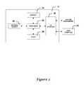
- FIG. 1is a block diagram of an illustrative HVAC system employing a controller having a programmable service event display mode
- FIG. 2is a block diagram of the controller and user interface of FIG. 1 ;
- FIG. 3is block diagram showing the controller of FIGS. 1-2 equipped with a programmable interface
- FIG. 4is a flow chart of an illustrative service event routine programmed within a controller equipped with a service event display mode
- FIG. 5is a view of an illustrative HVAC controller equipped with a touch screen interface
- FIG. 6is a pictorial view showing the illustrative controller and user interface of FIG. 5 during normal controller operation;
- FIG. 7is a pictorial view showing the illustrative controller and user interface of FIG. 5 after a service event has been detected;
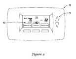
- FIG. 8is a view of another illustrative HVAC controller equipped with a display panel and keypad interface
- FIG. 9is a pictorial view showing the illustrative controller and user interface of FIG. 8 during normal controller operation;
- FIG. 10is a pictorial view showing the illustrative controller and user interface of FIG. 8 after a service event has been detected by the controller;
- FIG. 11is a block diagram of an illustrative controller having a display and an external interface
- FIGS. 12-13are pictorial views showing an illustrative controller and user interface having a background image displayed on part of the display;
- FIG. 14is a pictorial view showing another illustrative controller and user interface having an electronic image displayed on the display;
- FIG. 15is a schematic view of an illustrative controller and user interface displaying a plurality of electronic images in a slide show format
- FIG. 16is an illustrative view of an illustrative controller having a screensaver.
- FIGS. 17A-17Fare illustrative pictorial views of a controller having a menu for selecting electronic images for display.
- Controller 12may be operatively connected to one or more system components that can be activated to regulate various environmental conditions such as temperature, humidity and air quality levels occurring within a structure.
- the controller 12can be connected to a heater unit 14 and cooling unit 16 that can be activated to maintain the structure at a particular temperature level.
- a ventilation unit 18such as a fan or blower equipped with one or more dampers may be employed to regulate the volume of air delivered to the various rooms of the structure.
- a filtration unit 20 , UV lamp unit 22 , and humidifier/dehumidifier unit 24may also be provided to regulate the air quality and moisture levels within the structure.
- One or more local and/or remote sensors 26 as well as other system componentscan also be connected to controller 12 to monitor and regulate the environment, as desired.
- the system componentsmay be directly connected to a corresponding Input/Output (I/O) port or I/O pins on the controller 12 , and/or connected to the controller via a network or the like, as desired.
- I/OInput/Output
- the controller 12may include a user interface 28 that allows a user or service technician to transmit signals to and from the controller 12 .
- the user interface 44can include a touch screen, a liquid crystal display (LCD) panel and keypad, a dot matrix display, a computer, and/or any other suitable device for sending and receiving signals to and from the controller 12 .
- the controller 12can be configured to display servicing information on the user interface 28 to notify the user when a fault or malfunction has been detected, or when servicing is necessary or desirable.
- the controller 12can be programmed to display the name, logo, URL and/or telephone number of a designated contractor, a service referral organization, a utility, a retailer, a manufacturer, and/or some other person or organization when a fault or other service event has been detected in one or more of the system components.
- the controllermay display a different name, logo, URL and/or telephone number, depending on the nature of the service event detected and/or the component or unit that needs service.
- the name, logo, URL and/or telephone number of a designated heating contractormay be displayed when a service event related to the heating system is detected, and the name, logo, URL and/or telephone number of a designated security system contractor may be displayed when a service event related to the security system is detected.
- a service event code and/or short description of the service eventmay be displayed.
- such servicing informationcan be displayed prominently on a display unit, providing the user with information on where to call for servicing.
- the controller 12may be programmed to automatically contact a designated contractor, a service referral organization, a utility, a retailer, a manufacturer, and/or some other person or organization, requesting service for the detected event.
- a Telephone Access Module (TAM) 29may be provided.
- the TAM 29may call the appropriate person or organization when a service event is detected by the controller 12 . While a TAM is shown in FIG. 1 , it is contemplated that the controller 12 may notify an appropriate person or organization when a service event is detected via an internet connection, a wireless connection (e.g. cell phone), or any other suitable communication method, as desired.
- FIG. 2is a block diagram of the controller 12 and user interface 28 of FIG. 1 .
- the controller 12may include a processor 30 (e.g. a microprocessor/CPU), a storage memory 32 , a clock 34 , and an I/O interface 36 that connects the controller 12 to the various system components illustrated in FIG. 1 .
- An internal sensor 38 located within the controller 12can be employed to measure the temperature, humidity levels and/or other environmental conditions occurring within the structure. In some cases, the sensor 38 may be external to the controller 12 .
- FIG. 3is a block diagram showing the programmable controller 12 of FIGS. 1-2 equipped with an interface 40 .
- the interface 40may be configured to permit the manufacturer or other authorized technician to program the controller 12 to display servicing information on the user interface 40 when a fault is detected in one or more of the system components, or when the controller 12 has determined that a system component requires maintenance or other servicing.
- the interface 40can be used to set various equipment service event timers that can be used to remind the user to replace or clean the filter for the filtration unit 20 , the pads for the humidifier/dehumidifier unit 24 , the UV lamp for the UV lamp unit, the controller batteries, etc., after a certain period of time has elapsed.
- Other equipment service event timersmay, of course, be implemented depending on the particular application.
- the parameters for each equipment service event timercan be set to a particular default value, which can then be adjusted using the interface 40 , as desired.
- the controller 12can be configured to display a service reminder via the user interface 28 of FIG. 2 informing the user that service is suggested for the system.
- the interface 40may be provided as part of the user interface 28 described above, or may be provided as a separate interface from the user interface 28 .
- the interface 40may include a menu or screen accessible via the user interface 28 using a security code or password.
- the menu or screenmay be configured to permit only the manufacturer or other authorized technician or organization to program the servicing information into the controller 12 , if desired.
- the controller 12can be programmed at any time before, during or after the controller 12 has been installed.
- the interface 40may permit the servicing information to be programmed into the controller 12 in-house at the manufacturer, or at a later time during installation or servicing.
- the interface 40may include a data port for transferring data to the controller 12 , allowing the manufacturer and/or service technician to program the servicing information into the controller 12 .
- a service technician or manufacturermay upload servicing information into the controller 12 .
- This informationmay include, for example, a logo, telephone number, email address, web page URL, etc., of a contractor, service referral organization, retailer, utility or other organization, as desired.
- This datamay be uploaded from a PDA, laptop, or other portable or handheld device, if desired.
- the logomay be in a graphical representation stored in the memory of the controller.
- the logomay be in, for example, bitmap, jpeg, gif, tiff, or any other suitable format.
- the interface 40may be provided as part of a remote interface, allowing the manufacturer or other authorized technician to program the controller 12 at a location outside of the controller 12 .
- the interface 40may include a receiver that can be used to receive servicing information over a wireless connection, such as an infrared connection, over a cell phone network, over a wired connection such as a telephone line, or any other suitable connection.
- the interface 40may be connected to the World Wide Web (WW), which may allow the servicing information to be uploaded into the controller 12 from a remote location across the WWW.
- WWWWorld Wide Web
- the service event routinemay begin from a normal controller operation mode, indicated generally by block 44 .
- the controllermay be configured to check the operating status of one or more of the system components to determine if the system components are functioning properly, as indicated generally by block 46 .
- the controllermay periodically poll each of the system components and obtain current status information.
- the controllercan be configured to display servicing information such as the name, logo, URL, telephone number and/or other information for a designated contractor, service referral organization, manufacturer, retailer, utility and/or other person or organization.
- the controllermay also be configured to display a service event code, a description of the fault, and/or any other useful information, as indicated generally by block 48 .
- different servicing informationcan be displayed depending on which system component(s) indicated a positive service indicator. For example, one contractor logo and telephone number may be displayed if the cooling system provided a service indicator, and another contractor logo and telephone number may be displayed if the heating system provided a service indicator.
- the servicing informationcan be displayed temporarily for a certain period of time until the controller is reset and/or until the faulty system component is restored to normal operation.
- the controllercan be configured to determine whether any of the equipment service timers (if any) have elapsed, as indicated generally by block 50 . If, for example, the controller determines that the filter for the filtering unit has been in use for a certain period of time and likely requires replacement, the controller can be configured display a logo and telephone number for an authorized filter contractor or dealer. Information about the type of filter to replace as well as other pertinent servicing information can also be displayed, as desired.
- the controller 12can include a help mode that can be activated by the user to obtain servicing information.
- the usermay send a signal to the controller via a “help” button or other similar command.
- the controller 12can be configured to display servicing information such as the logo, telephone number, etc. of a designated contractor, service referral organization, manufacturer, retailer, utility and/or other person or organization as desired.
- the controllercan be configured to display the servicing information irrespective of whether a service indicator or expired equipment service event timer has been detected.
- the illustrative service event routine 42 shown in FIG. 4includes a particular sequence of events which occur during the routine 42 , it should be understood that the particular order at which each step occurs can be altered, if desired.
- the controllermay be configured to perform each step in parallel, or in a sequence different from that illustrated in FIG. 4 .
- one or more steps in the service event routine 42may be eliminated, if desired, depending on type of controller employed.
- FIG. 5is a view of an illustrative controller 56 equipped with a user interface 58 for displaying servicing information when a service event is detected.
- user interface 58includes a touch screen 60 configured to display information and transmit signals to and from the controller 56 .
- suitable touch screens 60 for use with the controller 56may include resistive, capacitive, infrared or surface acoustic wave (SAW) type touch screens.
- the touch screen 60may be either inset or recessed within a controller housing 62 , as shown in FIG. 5 , or may be provided as a separate component for use with a personal digital assistant (PDA), PC computer, or other remote device.
- PDApersonal digital assistant
- the touch screen 60can be provided as part of a liquid crystal display (LCD) panel, cathode ray tube (CRT), dot matrix display, or other suitable display device.
- LCDliquid crystal display
- CRTcathode ray tube
- dot matrix displayor other suitable display device.
- FIG. 6is a pictorial view showing the illustrative controller 56 and user interface 58 of FIG. 5 during normal controller operation.
- the touch screen 60may be configured to display a main menu screen 64 that provides the user with information about the operational status of the controller 56 , the current inside and outside temperature, the current time and day of week, the current heat and/or cool set point, as well as other operational information.
- the main menu screen 64may be the default screen that appears on the touch screen 60 when the controller 56 is initially activated, after a loss of power has occurred, or after no activity has been detected by the user interface 58 for a certain period of time (e.g. after 1 minute of non-activity).
- the controller 56can be configured to cycle through one or more menus or screens to view and, if desired, modify various operational settings within the controller 56 .
- the usercan use the touch screen 60 to adjust the current temperature or humidity levels, change the clock or date settings on the controller 56 , set a vacation schedule on the controller 56 that can be run while the user is away, etc.
- the touch screen 60may also be used to check the status of the various system components connected to the controller 56 .
- FIG. 7is a pictorial view showing the illustrative controller 56 and user interface 58 of FIG. 6 after a service event has been detected.
- the controller 56can be configured to display a service event display screen 66 on the touch screen 70 that informs the user that a service event has been detected.
- the service event display screen 66may include, for example, a logo 68 and telephone number 70 indicating where to call for servicing or replacement. Other information in addition to, or in lieu of, the logo 68 and telephone number 70 may also be provided on the service event display screen 66 , as desired.
- a service event code and/or short description of the service eventmay also be displayed, as shown at 69 .
- the service event codemay help a service technician diagnose the problem on the phone and possibly help provide a corrective action to the user via the phone. Also, the service event code may help the service technician determine what parts to order or bring to correct the problem.
- a short description of the service eventmay help the user identify and possibly correct the problem. For example, if the service event was triggered as a result of the controller 56 determining that an equipment service event timer has expired, the controller 56 can be configured to display the particular device requiring service, and a recommended course of action. If, for example, an equipment service event timer for the filter has expired, the controller 56 can be configured to display the text “REPLACE FILTER” or other similar text on the touch screen 60 , along with an appropriate logo, telephone number, and/or address for an authorized dealer of the filter, along with the part number of the filter, if desired. Similar messages can be displayed for other system components such as the humidifier pad, UV lamp, and batteries, as necessary.
- the service event display screen 66can be triggered when the controller 56 detects a fault in one or more of the system components, or when an equipment service event timer previously programmed in the controller 56 expires.
- the service event display screen 66can be activated by the user by pressing one or more of the icon buttons on the touch screen 60 , causing the controller 56 to display the desired servicing information on the screen 60 .
- FIG. 8is a view of another illustrative controller 72 equipped with a user interface 74 for displaying servicing information when a service event is detected.
- user interface 74includes a display panel 76 and a series of buttons 78 , 80 that can be pressed by the user to scroll through various menus or screens displayable on the display panel 76 .
- the display panel 76can include any number of suitable display devices, including, for example, a backlit LCD panel or LED screen.
- FIG. 9is a pictorial view showing the illustrative controller 72 and user interface 74 of FIG. 8 during normal controller operation.
- the controller 72can be configured to display a main menu screen 82 on the display panel 76 , similar to that described above with respect to FIG. 6 .
- the controller 72can be configured to display a service event display screen 82 on the display panel 76 that informs the user that a service event has been detected.
- the service event display screen 82may include, for example, a logo 86 and telephone number 88 indicating where to call for servicing or replacement. Other information in addition to, or in lieu of, the contractor logo 86 and telephone number 88 may also be provided on the service event display screen 84 , as desired.
- the service event display screen 84can be triggered when the controller 72 detects a fault in one or more of the system components, or when an equipment service event timer previously programmed in the controller 72 expires.
- the service event display screen 84can be activated by the user by pressing one of the buttons 78 , 80 (e.g. a help button 12 ), causing the controller 72 to display the desired servicing information on the display panel 76 .
- FIG. 11is a block diagram of an illustrative HVAC controller having a user interface 28 with a display, and an external interface 27 for interfacing with an external data source 31 .
- the HVAC controller shown in FIG. 11may, in some cases, be similar in many respects to that shown and described with reference to FIG. 1 . That is, the HVAC controller of FIG. 11 may be operatively connected to one or more system components, such as, for example, a heating unit, a cooling unit, a ventilation unit, a filtration unit, a UV lamp unit, a humidifying/dehumidifying unit, and/or one or more local and/or remote sensors, as discussed with respect to FIG. 1 . In some cases, the HVAC controller may be a thermostat.
- the illustrative HVAC controller of FIG. 11may have a controller 12 that is connected to the user interface 28 .
- the controller 12may any suitable controller such as a microprocessor, a microcontroller or the like.
- the user interface 28may include a display such as a touch screen display. In some cases, the user interface 28 may include a display and one or more buttons, knobs, dials or other user input devices.
- the display of the user interface 28may be, for example a liquid crystal display (LCD), a dot matrix display, a plasma display, and/or any other suitable type of display, preferably capable of displaying electronic images.
- the controller 12is shown coupled to an external interface 27 .
- the external interface 27may be adapted to provide an interface between the controller 12 and an external data source 31 .
- the controller 12may in some instances have a memory, and the external interface 27 may facilitate uploading and/or downloading data between the controller 12 and the external data source 31 .
- the external interface 27may facilitate uploading electronic images from an external data source 31 to the controller 12 , and the controller 12 may display the electronic images files on the display of the user interface 28 .
- the one or more electronic images that are uploaded from the external data source 31may be displayed on the display of the user interface 28 as a background image (i.e. wallpaper image), an image on only part of the display, as a sequence of slide show images, a screensaver image, a scrolling text line image, and/or any other suitable image as desired.
- the electronic imagesmay include still images, video images, text images, computer generated images, flash player images, or any other suitable image or image sequence, as desired.
- the electronic imagesmay be in a JPEG, GIF, BMP, TIFF, PNG, WMF, PCX, MPEG, SWF (Adobe Flash), SCR (WindowsTM Screen Saver Format), or any other suitable format.
- External interface 27may include a wired and/or wireless interface.
- the external interface 27may include a wired connector interface, a wireless interface (e.g. an optical interface and/or an RF interface), or any other suitable interface, as desired.
- the wired connector interfacemay include one or more of a Universal Serial Bus (USB) interface, an Ethernet interface, a FireWire interface, a digital camera or cellular phone interface, and/or any other suitable electronic interface or interfaces, as desired.
- the wired connector interfacemay include a port or connector for accepting one or more removable flash memories.
- Example removable flash memoriesinclude Compact Flash (CF), Secure Digital (SD), MicroSD, XD, thumb drives, and/or any other suitable removable memory, as desired.
- the wireless interfacemay include, for example, a radio frequency (RF) wireless interface, an infrared wireless interface, a microwave wireless interface, and/or any other suitable wireless interface, as desired.
- the wireless interfacemay operate according to one or more wireless protocols, such as, for example, a cellular communication protocol, the ZigBee protocol, the Bluetooth protocol, the WiFi protocol, an IrDA protocol, a dedicated short range communication (DSRC) protocol, the EnOcean protocol, and/or any other wireless protocol, as desired.
- a radio frequency (RF) wireless interfacesuch as, for example, a cellular communication protocol, the ZigBee protocol, the Bluetooth protocol, the WiFi protocol, an IrDA protocol, a dedicated short range communication (DSRC) protocol, the EnOcean protocol, and/or any other wireless protocol, as desired.
- DSRCdedicated short range communication
- the external data source 31may be any suitable data source that is capable of interfacing with the external interface 27 .
- the external data source 31may be computer, a network (e.g. private network or World Wide Web), a cell phone, a PDA, a removable flash memory, or any other external data source, as desired. It is contemplated that the controller 12 may upload data from the external data source 31 and/or download data to the external data source 31 via the external interface 27 .
- the controller 12may upload one or more electronic images from the external data source 31 , and then display the uploaded electronic images on the display of the user interface 28 .
- controller 12may include a memory (internal and/or external) for storing at least one of the one or more electronic images uploaded from the external data source 31 .
- the memory of the controller 12may be RAM, ROM, EEPROM, Flash memory, and/or any other suitable type of memory, as desired.
- the controller 12may be configured to read at least one electronic image stored in the external data source 31 , before displaying the at least one electronic image on the display of the user interface 28 .
- the memory of the controller 12may only store a subset of the electronic images to be displayed, with the remainder of the electronic images stored on the external data source 31 .
- the controller 12may read up a desired electronic image or set of electronic images from the external data source 31 , and display the electronic images or set of electronic images on the display of the user interface 28 .
- the controller 12may read up another desired electronic image or set of electronic images from the external data source 31 , and display the other electronic images or set of electronic images on the display of the user interface 28 . This may reduce the memory requirements of the controller 12 , by using the external data source 31 as a storage medium. However, the external data source 31 may need to remain connected to the external interface 27 during operation.
- the external data source 31may include electronic images from, for example, a digital camera.
- the controller 12may receive a first electronic image from the external data source 31 , such as, for example, a removable flash memory, and display the first electronic image on the user interface 28 .
- controller 12may receive a second electronic image from the external data source 31 and display the second electronic image on the user interface 28 .
- This illustrative embodimentmay use the external data source 31 as a storage medium for storing some or all of the electronic images while the controller 12 selects and/or displays the electronic images on the display of the user interface 28 .
- the controller 12may read up the desired electronic images from the external data source 31 , and store the electronic images in a local memory that is accessible by controller (internal and/or external to the controller by within the HVAC controller). Then, during operation, the controller 12 may read up a desired electronic image from the local memory, and display the electronic images on the display of the user interface 28 .
- the external data source 31may not need to remain connected during operation.
- the external data source 31may include electronic images from, for example, a digital camera.
- the controller 12may upload and store a number of electronic images from the external data source 31 , and in some cases all of the electronic images, and then display one or more of the uploaded electronic images on the display of the user interface 28 .
- the external data source 31may not be used by the controller 12 as storage medium after the electronic images have been uploaded to the controller 12 and while the controller 12 selects and/or displays the electronic images on the display of the user interface 28 .
- the controller 12may download electronic images and/or other information to the external data source 31 via the external interface 27 .
- the controller 12may download one or more electronic images to the external data source 31 , and the external data source 31 may then be used to upload the one or more electronic images to another device, such as another HVAC controller, a computer, a PDA and/or any other suitable device.
- the controller 12may download one or more programming parameters, such as set points, schedules, confirmation information, or any other information to the external data source 31 , and the external data source 31 may then be used to upload the information to another device, such as another HVAC controller, a computer, a PDA and/or any other suitable device.
- controller 12may include an image selection tool to help a user in selecting which of the at least one electronic images to display on the display of the user interface 28 .
- the image selection toolmay display thumbnail images of the at least one electronic images on the user interface 28 to aid a user in selecting which of the electronic images to display on the user interface 28 , and in some cases for what purpose.
- the image selection toolmay display a list of the at least one electronic images on the user interface 28 to aid the user in selecting which of the electronic images to display on the user interface 28 , and in some cases for what purpose.
- the controllermay provide one or more menus on the display of the user interface 28 to help the user upload, download, categorize, select, organize, move, delete, customize or otherwise work with the available electronic images.
- the controller 12may be configured to select and display one of at least two electronic images according to one or more parameters of the HVAC controller.
- Example parametersmay include a time of day related parameter, a date related parameter, a season related parameter, an operating mode related parameter, an outside temperature related parameter, an inside temperature related parameter, a ventilation related parameter, a schedule related parameter, a schedule period parameter, a local weather parameter, a parameter related to the birthday, anniversary and/or another special day of a user of the HVAC controller, and/or any other suitable parameter, as desired.
- the controller 12may be programmed to select and display a particular electronic image depending on the state or value of a parameter of the HVAC controller. For example, a first electronic image may be displayed when rainy weather is predicted, a second electronic image may be displayed when sunny weather is predicted, a third electronic image may be displayed when cloudy weather is predicted, and a fourth electronic image may be displayed when snowy weather is predicted. In this example, if the weather is predicted to be rainy, controller 12 may select and display the first electronic image, if the weather is predicted to be sunny, the controller 12 may display the second image, and so on.
- different electronic imagesmay be associated with each of the four seasons of the year, and displayed accordingly.
- one or more electronic imagesmay be associated with at least some holidays, such as, for example, Christmas, Halloween, 4 th of July, Easter, and/or any other holiday, as desired.
- one or more electronic imagesmay be associated with the time or period of a day.
- the controller 12may have an electronic image associated with each of a wake, a leave, a return, and a sleep period of a thermostat schedule. Then, the controller 12 may display the associated images during the corresponding periods of the thermostat schedule. More generally, it is contemplated that one or more electronic images may be associated with any suitable parameter of the HVAC controller, as desired, and displayed accordingly.
- the controller 12may display regularly updated electronic images or other information, such as, for example, weather, traffic and/or news information.
- the controllermay be in communication with the World Wide Web (WWW) or some other information source via external interface 27 .
- the controller 12may display weather information as the weather changes including providing electronic images associates with severe weather alerts and/or radar images (including radar loops if desired).
- the controller 12may provide electronic images of news information, such as, for example, top news stories, which may be retrieved by one or more media organizations via a wired or wireless network (e.g. the WWW).
- controller 12may be configured to upload updated weather information, such as local or national weather forecasts, radar information, and/or severe weather alerts.
- controller 12may be configured to upload updated news information, such as, for example, top news stories, local headlines, national headlines, world headlines, sports headlines, business headlines, or any other news data, as desired.
- the usermay enter information related to the location of the thermostats and/or information related to his/her interests, and the controller 12 may then displayed information that is most relevant to the user's location and/or interests on the display of the user interface 28 .
- the controller 12may be configured to upload one or updates to the controller software and/or operating system from the external data source 31 , and then install the updated controller software and/or operating system on the controller 12 .
- the software updatesmay, in some cases, be or include firmware updates.
- the software updatesmay correct known bugs, improve performance, add functionality, and/or otherwise improve the operation of the controller 12 .
- FIGS. 12-13are pictorial views showing an illustrative HVAC controller 100 and user interface 106 having a background image displayed on part of the display.
- user interface 106includes an LCD touch screen 102 configured to display information and transmit signals to and from the controller 100 .
- suitable touch screens 102may include resistive, capacitive, infrared or surface acoustic wave (SAW) type touch screens.
- the touch screen 102may be either inset or recessed within a controller housing 110 , as shown in FIG. 12 .
- the touch screen 102can be provided as part of a liquid crystal display (LCD) panel, cathode ray tube (CRT), dot matrix display, or any other suitable display device.
- LCDliquid crystal display
- CRTcathode ray tube
- dot matrix displayor any other suitable display device.
- the touch screen 102may be configured to display a main menu screen 108 that provides the user with information about the operational status of the HVAC controller 100 , the current inside and outside temperature, the current time and day of week, the current heat and/or cool set point, as well as other operational information.
- the main menu screen 108may be the default screen that appears on the touch screen 102 when the controller 100 is initially activated, after a loss of power has occurred, or after no activity has been detected by the user interface 106 for a certain period of time (e.g. after 1 minute of non-activity).
- the controller 100can be configured to access one or more sub-menus or screens to view and, if desired, modify various operational settings of the HVAC controller 100 .
- the usermay use the touch screen 102 to adjust the current temperature or humidity levels, change the clock or date settings of the controller 100 , set a vacation schedule on the controller 100 that can be run while the user is on vacation, etc.
- the touch screen 102may also be used to check the status of the various system components connected to the HVAC controller 100 .
- touch screen 102may be configured to display an electronic image 104 as a background image, or wallpaper, on the display.
- the electronic image 104is illustrated in dashed lines in FIG. 12 .
- the electronic image 104may be uploaded onto the controller 100 via an external interface (see FIG. 11 ), or, in other cases, the electronic image 104 may be preloaded onto the controller 100 , if desired.
- the one or more thermostat parametersmay be displayed on top of at least a portion of the background image 104 .
- the one or more thermostat parameters that are displayed on top of the background image 104include a date/time parameter, an outdoor temperature parameter, a HVAC status parameter and an inside temperature parameter.
- theseare only illustrative in nature.
- the electronic image 104can be displayed on the main menu screen 108 . It is contemplated that the electronic image 104 may be displayed on only the main menu screen 108 of the controller, or on the main menu screen 108 and at least some of one or more sub-menus or screens of the controller 100 , as desired. In some cases, electronic image 104 may be displayed on only a portion of touch screen 102 , as shown. However, in other cases, it is contemplated that electronic image 104 may be displayed on substantially the entire area of the touch screen 102 display, if desired.
- controller 100may be configured to display regularly updated news and/or weather information in a display box or region (not shown) on the display.
- touch screen 102may include a box or region including, for example, scrolling text displaying the regularly updated electronic images and/or data, such as in a crawl along a top or bottom of the of the display screen.
- the regularly updated electronic images and/or datamay be displayed as a background image, or wallpaper, on the display, if desired.
- FIG. 13is similar to FIG. 12 , with the controller 100 having a user interface 106 displaying an electronic image 112 as a background image, or wallpaper.
- information about the operational status of the controller 100 , the current inside and outside temperature, the current time, date, and day of week, the current heat and/or cool set point, the humidity, as well as other operational informationmay be displayed on top of the electronic image 112 , if desired.
- the electronic image 112shows clouds. However, it is contemplated that any suitable electronic image 112 may be used, as desired.
- FIG. 14is a pictorial view showing another illustrative controller 100 and user interface 106 having an electronic image 114 displayed on only part of the display.
- the touch screen 102includes a first region and a second region.
- the first region of the touch screen 102may display the electronic image 114 as a background image.
- the second region of the touch screen 102may display one or more operational parameters, such as thermostat parameters.
- the first region and the second regionmay not overlap, but this is not required.
- it is contemplated that at least some of the one or more thermostat parametersmay overlap or overlay a portion of the electronic image 114 as shown in FIGS. 12-13 , but this is not required or even desired in some embodiments.
- the first region displaying the electronic image 114is illustrated as containing a left side of the touch screen 102 .
- the first regionmay be positioned on the right side of the touch screen 102 , in the middle of the touch screen 102 having the one or more thermostat parameters on both the right and left side of the first region, along the top and/or bottom of the touch screen 102 , or any other suitable position, as desired.
- FIG. 15is a schematic view of an illustrative controller 100 and user interface 106 displaying a plurality of electronic images 116 , 118 , 120 in a slide show format. Again, the electronic images are illustrated in dashed lines, with subsequently displayed electronic images illustrated below the controller 100 .
- the controller 100may be configured to sequentially display two or more electronic images 116 , 118 , and 120 on at least a portion of the touch screen 102 .
- the sequential displaymay be in slide show format.
- the slide showmay function as a screensaver for the controller 100 , and may automatically activate after a period of no user interaction.
- the usermay select which electronic images to include in the slide show.
- the controller 100may select the electronic images to include in the slide show, such as all available electronic images, or some portion thereof.
- the electronic images 116 , 118 , 120may be selected from a group of uploaded and/or preloaded electronic images, if desired.
- an order of displaymay be determined.
- the usermay select the order of display, while in other cases, the controller 100 may determine the order.
- the order of displaymay be random, by date, by file name, etc., if desired.
- the controller 100may be configured to allow a user to select which of the electronic images 116 , 118 , 120 will be shown more often (e.g. given priority) in the slide show format than other available electronic images.
- the slide showmay function as a screen saver for the controller 100 . That is, the slide show may be automatically initiated after a period of non-use by the user. In other cases, the slide show may be initiated by a user command, a time of day, a programmed schedule of the controller 100 , or at any other suitable time.
- the controller 100may sequentially display the plurality of electronic images 116 , 118 , 120 on the display.
- the sequential displaymay display a first electronic image 116 for a period of time. In some cases, the period of time may be selectable by the user. Then, the controller may display a second electronic image 118 for a period of time, and so forth until the controller 100 display a last electronic image 120 . Then, and in some cases, the slide show may be repeated, or the slide show may terminate, as desired.
- the controller 100may display each electronic image 116 , 118 , 120 for a period of time.
- the period of timemay be in the range of 1 second to 5 minutes, such as, for example, 1 second, 2 seconds, 3 seconds, 10 seconds, 20 seconds, 30 seconds, or 1 minute.
- any suitable period of timemay be used, as desired.
- the period of time that an electronic image is displayedmay be about the same for each image, but this is not required.
- the slide showmay have a transition between electronic images, such as, for example, a slide show effect.
- the slide show effectsmay include, but is not limited to, a fade effect, a dissolve effect, a shutter effect, a cross-comb effect, a mask effect, a brick effect, a fly-in effect, as well as many other slide show effects.
- the slide show effectmay vary throughout the slide show, but this is not required.
- the controller 100may display one or more parameters of the controller 100 during the slide show.
- the controller 100may include a parameter box 122 displayed on a portion of the touch screen 102 during the slide show.
- the parameter box 122is positioned across the bottom of the touch screen 102 .
- a parameter box 122may be positioned on the top, right side, left side, or in any other suitable location on the touch screen, as desired.
- one or more parameters of the controller 100may be displayed in any suitable manner during the slide show, if desired.
- a previous and/or next buttonmay be provided on the touch screen 102 during the slide show. The previous and/or next buttons may allow the user to manually sequence through the slide show.
- FIG. 16is an illustrative view of an illustrative controller 100 having a screensaver.
- the screensavermay include one electronic image 124 , such as, for example, a digital still image, a video, an electronic animation, or any other suitable electronic image, as desired.
- the electronic image 124again illustrated in dashed lines, may be uploaded to the controller 100 via the external interface 27 (see FIG. 11 ).
- the animationmay include a scrolling marquee, 3D boxes, flying objects, moving/changing shapes, and/or any other suitable animation, as desired.
- the screensavermay be downloaded from the World Wide Web, or provided to the controller 100 by way of a removable memory card, as desired.
- the particular electronic image 124 used for the screen savermay be selected by the user, and/or in some cases, may depend on one or more current parameters of the controller 100 , if desired.
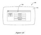
- FIGS. 17A-17Fare illustrative pictorial views of a controller having a menu for selecting electronic images for display.
- FIG. 17Ais an illustrative view of a controller 100 displaying a menu 130 after selecting the “Menu” option of FIG. 13 .
- the illustrative menu 130may include multiple options to control various settings of controller 100 . For example, there may be a set/create schedule option, a vacation option, a humidification option, a dehumidification option, a system information option, a date/time option, a preferences option, a temporary schedule option, a schedule fan option, a security settings option, an installer set up option, as well as any other settings option, as desired.
- menu 132may include many controller preferences, such as, for example, a reminders option, a Fahrenheit/Celsius option, a 12h/24h clock option, a display option, a language option, a schedule option, an adaptive intelligent recovery option, a restore energy star settings option, a wireless device manager option, a daylight savings time option, as well as any other preference option, as desired.
- menu 132may also include a previous menu option to return to menu 130 of FIG. 17A , if desired.
- menu 134may be displayed.
- Menu 134may include many options that may control display settings.
- menu 134may include a backlight option, a contrast option, a screensaver option, a wallpaper option, as well as many other display options, as desired.
- menu 134may include a previous menu option to return to menu 132 of FIG. 17B , and a help option that may display help information related to the use of the display option of menu 132 .
- menu 136When the screensaver option of menu 134 is selected, menu 136 , as shown in FIG. 17D , may be displayed.
- Menu 136or the screensaver settings menu, may include settings to control the screensaver for the controller 100 .
- menu 136may include a screensaver timeout setting that may be adjusted by the user to increase or decrease the screensaver timeout time.
- the screensaver timeout timemay range from 1 minute to 90 minutes. However, it is contemplated that any suitable time may be used, as desired.
- menu 136may also include an image option 137 .
- the image option 137may control the settings of the one or more electronic images that are displayed by the screensaver, and in some cases, the desired screensaver effects (e.g. single image screen saver, slideshow, animation, etc.). Additionally, in some embodiments, menu 136 may include a cancel option, a help option, and a done option. In some cases, though not explicitly illustrated in FIG. 17D , menu 136 or image option 137 may include a transition option that may control the settings of the transitions or slide show effects between electronic images of the screensaver, if a slide show is desired.
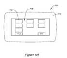
- menu 138may include one or more thumbnails 142 or icons, each corresponding to one or more electronic images uploaded and/or preloaded onto controller 100 .
- menu 138 displayeda user may select one or more desired images for use by a slide show and/or screensaver by selecting one or more thumbnails 142 .
- a usermay simply touch the touch screen 102 on the thumbnail 142 highlighting the thumbnail 142 .
- a usermay touch the touch screen 102 on the selected thumbnail 142 , removing the highlighting from the thumbnail 142 .
- the usermay select “Done” to save the settings in memory. If a user does not want the settings saved, the user may select “Cancel” to exit the menu 138 .
- menu 134 of FIG. 17Ca wallpaper setting option is selected, a menu similar to menu 138 may be displayed allowing the user to select one or more thumbnails for the wallpaper image, as desired.
- menu 138or any other suitable menu, may include an option to display a thumbnail or icon for one or more regularly updated electronic images from the World Wide Web or other information source on the touch screen 102 display, as desired.
- a thumbnail or iconmay be presented for displaying regularly updated weather, news, or any other information, and sometimes an option to select the format, as desired.
- there may be an additional menu option to select the format for the wallpapersuch as, for example, the entire display wallpaper or split display wallpaper with the electronic image in a first region and the controller 100 parameters in a second region, as described with respect to FIG. 14 .
- menu 140may be provided when selecting the image option of menu 136 and/or the wallpaper option of menu 134 , if desired.
- Menu 140may provide a list of electronic images that may be selected to display in the screensaver and/or wallpaper.
- the listmay include a box next to each electronic image indicating if the image is selected.
- the image namemay be highlighted in the list if selected.
- any suitable method of selecting the image(s)may be used, as desired.
- menu 138 and/or menu 140may include an option to preview an image full size on the display. For example, tapping on the touch screen 102 twice in a rapid manner may expand the thumbnail 142 or list item to a full screen preview. Furthermore, it is contemplated that any suitable method of creating a full screen preview may be used, as desired. Once all the desired electronic images are selected, a user may select the “Done” option to store the settings in controller 100 memory.
- a menumay be provided for selecting a theme or skin for the user interface of the controller 100 .
- a themetypically includes a set of colors, sounds, images, icons, screensavers, and/or background images that are consistent with a specified theme.
- one illustrative thememay include a Halloween theme, where the set of colors, sounds, images, icons, screensavers, and/or background images that consistent with a Halloween theme.
- the size and locations of the menus, parameter and other features of the user interfaceare typically not changed.
- a skinis typically changes the size and locations of the menus, parameter and other features of the user interface.
- one illustrative skinmay include a star wars skin, wherein the size, shape and locations of the menus, parameter and other features of the user interface are changed to reflect a star wars feel.
- one or more themes and/or skinsmay be uploaded to the controller 100 via the external interface 27 (see FIG. 11 ), and a menu similar to that shown in FIGS. 17E-17F may be used to select a theme or skin for use by the controller 100 .
Landscapes
- Engineering & Computer Science (AREA)
- General Engineering & Computer Science (AREA)
- Physics & Mathematics (AREA)
- General Physics & Mathematics (AREA)
- Mechanical Engineering (AREA)
- Chemical & Material Sciences (AREA)
- Combustion & Propulsion (AREA)
- Signal Processing (AREA)
- Theoretical Computer Science (AREA)
- Fuzzy Systems (AREA)
- Mathematical Physics (AREA)
- Automation & Control Theory (AREA)
- Human Computer Interaction (AREA)
- Air Conditioning Control Device (AREA)
- Selective Calling Equipment (AREA)
Abstract
Description
Claims (36)
Priority Applications (3)
| Application Number | Priority Date | Filing Date | Title |
|---|---|---|---|
| US11/840,290US8554374B2 (en) | 2003-12-02 | 2007-08-17 | Thermostat with electronic image display |
| US14/047,825US9081393B2 (en) | 2003-12-02 | 2013-10-07 | Thermostat with electronic image display |
| US14/729,500US10423140B2 (en) | 2003-12-02 | 2015-06-03 | Thermostat with electronic image display |
Applications Claiming Priority (3)
| Application Number | Priority Date | Filing Date | Title |
|---|---|---|---|
| US10/726,243US7225054B2 (en) | 2003-12-02 | 2003-12-02 | Controller with programmable service event display mode |
| US11/752,816US7801646B2 (en) | 2003-12-02 | 2007-05-23 | Controller with programmable service event display mode |
| US11/840,290US8554374B2 (en) | 2003-12-02 | 2007-08-17 | Thermostat with electronic image display |
Related Parent Applications (1)
| Application Number | Title | Priority Date | Filing Date |
|---|---|---|---|
| US11/752,816Continuation-In-PartUS7801646B2 (en) | 2003-12-02 | 2007-05-23 | Controller with programmable service event display mode |
Related Child Applications (1)
| Application Number | Title | Priority Date | Filing Date |
|---|---|---|---|
| US14/047,825ContinuationUS9081393B2 (en) | 2003-12-02 | 2013-10-07 | Thermostat with electronic image display |
Publications (2)
| Publication Number | Publication Date |
|---|---|
| US20070278320A1 US20070278320A1 (en) | 2007-12-06 |
| US8554374B2true US8554374B2 (en) | 2013-10-08 |
Family
ID=38788968
Family Applications (3)
| Application Number | Title | Priority Date | Filing Date |
|---|---|---|---|
| US11/840,290Expired - LifetimeUS8554374B2 (en) | 2003-12-02 | 2007-08-17 | Thermostat with electronic image display |
| US14/047,825Expired - LifetimeUS9081393B2 (en) | 2003-12-02 | 2013-10-07 | Thermostat with electronic image display |
| US14/729,500Expired - LifetimeUS10423140B2 (en) | 2003-12-02 | 2015-06-03 | Thermostat with electronic image display |
Family Applications After (2)
| Application Number | Title | Priority Date | Filing Date |
|---|---|---|---|
| US14/047,825Expired - LifetimeUS9081393B2 (en) | 2003-12-02 | 2013-10-07 | Thermostat with electronic image display |
| US14/729,500Expired - LifetimeUS10423140B2 (en) | 2003-12-02 | 2015-06-03 | Thermostat with electronic image display |
Country Status (1)
| Country | Link |
|---|---|
| US (3) | US8554374B2 (en) |
Cited By (61)
| Publication number | Priority date | Publication date | Assignee | Title |
|---|---|---|---|---|
| US20090158188A1 (en)* | 2007-12-14 | 2009-06-18 | Honeywell International Inc. | Configurable wall module system |
| US20100107103A1 (en)* | 2008-10-27 | 2010-04-29 | Lennox Industries Inc. | System and method of use for a user interface dashboard of a heating, ventilation and air conditioning network |
| US20150012863A1 (en)* | 2012-12-28 | 2015-01-08 | Panasonic Intellectual Property Corporation Of America | Control method |
| US9081393B2 (en) | 2003-12-02 | 2015-07-14 | Honeywell International Inc. | Thermostat with electronic image display |
| US20160265813A1 (en)* | 2015-03-12 | 2016-09-15 | Tyler Charles Krumm | Flameless Friction Heater |
| US9513770B1 (en)* | 2012-11-02 | 2016-12-06 | Microstrategy Incorporated | Item selection |
| US9560482B1 (en) | 2015-12-09 | 2017-01-31 | Honeywell International Inc. | User or automated selection of enhanced geo-fencing |
| US9584119B2 (en) | 2013-04-23 | 2017-02-28 | Honeywell International Inc. | Triac or bypass circuit and MOSFET power steal combination |
| US9609478B2 (en) | 2015-04-27 | 2017-03-28 | Honeywell International Inc. | Geo-fencing with diagnostic feature |
| US9628951B1 (en) | 2015-11-11 | 2017-04-18 | Honeywell International Inc. | Methods and systems for performing geofencing with reduced power consumption |
| US9628074B2 (en) | 2014-06-19 | 2017-04-18 | Honeywell International Inc. | Bypass switch for in-line power steal |
| US9673811B2 (en) | 2013-11-22 | 2017-06-06 | Honeywell International Inc. | Low power consumption AC load switches |
| US9683749B2 (en) | 2014-07-11 | 2017-06-20 | Honeywell International Inc. | Multiple heatsink cooling system for a line voltage thermostat |
| US9806705B2 (en) | 2013-04-23 | 2017-10-31 | Honeywell International Inc. | Active triac triggering circuit |
| US9832034B2 (en) | 2011-07-27 | 2017-11-28 | Honeywell International Inc. | Systems and methods for managing a programmable thermostat |
| USD806114S1 (en)* | 2015-12-24 | 2017-12-26 | Samsung Electronics Co., Ltd. | Display screen or portion thereof with transitional graphical user interface |
| US9857091B2 (en) | 2013-11-22 | 2018-01-02 | Honeywell International Inc. | Thermostat circuitry to control power usage |
| US9860697B2 (en) | 2015-12-09 | 2018-01-02 | Honeywell International Inc. | Methods and systems for automatic adjustment of a geofence size |
| US9890971B2 (en) | 2015-05-04 | 2018-02-13 | Johnson Controls Technology Company | User control device with hinged mounting plate |
| US9900174B2 (en) | 2015-03-06 | 2018-02-20 | Honeywell International Inc. | Multi-user geofencing for building automation |
| US9967391B2 (en) | 2015-03-25 | 2018-05-08 | Honeywell International Inc. | Geo-fencing in a building automation system |
| US9971364B2 (en) | 2012-03-29 | 2018-05-15 | Honeywell International Inc. | Method and system for configuring wireless sensors in an HVAC system |
| US9983244B2 (en) | 2013-06-28 | 2018-05-29 | Honeywell International Inc. | Power transformation system with characterization |
| CN108109581A (en)* | 2018-01-16 | 2018-06-01 | 深圳鑫亿光科技有限公司 | Interactive LED display and its display methods |
| US10057110B2 (en) | 2015-11-06 | 2018-08-21 | Honeywell International Inc. | Site management system with dynamic site threat level based on geo-location data |
| US10063387B2 (en) | 2012-08-07 | 2018-08-28 | Honeywell International Inc. | Method for controlling an HVAC system using a proximity aware mobile device |
| US10082312B2 (en) | 2013-04-30 | 2018-09-25 | Honeywell International Inc. | HVAC controller with multi-region display and guided setup |
| US10139843B2 (en) | 2012-02-22 | 2018-11-27 | Honeywell International Inc. | Wireless thermostatic controlled electric heating system |
| US10162327B2 (en) | 2015-10-28 | 2018-12-25 | Johnson Controls Technology Company | Multi-function thermostat with concierge features |
| US10306403B2 (en) | 2016-08-03 | 2019-05-28 | Honeywell International Inc. | Location based dynamic geo-fencing system for security |
| US10302322B2 (en) | 2016-07-22 | 2019-05-28 | Ademco Inc. | Triage of initial schedule setup for an HVAC controller |
| US10317102B2 (en) | 2017-04-18 | 2019-06-11 | Ademco Inc. | Geofencing for thermostatic control |
| US10318266B2 (en) | 2015-11-25 | 2019-06-11 | Johnson Controls Technology Company | Modular multi-function thermostat |
| US10410300B2 (en) | 2015-09-11 | 2019-09-10 | Johnson Controls Technology Company | Thermostat with occupancy detection based on social media event data |
| US10436977B2 (en) | 2013-12-11 | 2019-10-08 | Ademco Inc. | Building automation system setup using a remote control device |
| US10458669B2 (en) | 2017-03-29 | 2019-10-29 | Johnson Controls Technology Company | Thermostat with interactive installation features |
| US10489038B2 (en) | 2011-01-08 | 2019-11-26 | Michael Edward Klicpera | Remote apparatus for displaying, monitoring and controlling shower, bath or faucet water parameters |
| US10488062B2 (en) | 2016-07-22 | 2019-11-26 | Ademco Inc. | Geofence plus schedule for a building controller |
| US10516965B2 (en) | 2015-11-11 | 2019-12-24 | Ademco Inc. | HVAC control using geofencing |
| US10546472B2 (en) | 2015-10-28 | 2020-01-28 | Johnson Controls Technology Company | Thermostat with direction handoff features |
| US10605472B2 (en) | 2016-02-19 | 2020-03-31 | Ademco Inc. | Multiple adaptive geo-fences for a building |
| US10613555B2 (en) | 2012-07-26 | 2020-04-07 | Ademco Inc. | HVAC controller with wireless network based occupancy detection and control |
| US10655881B2 (en) | 2015-10-28 | 2020-05-19 | Johnson Controls Technology Company | Thermostat with halo light system and emergency directions |
| US10677484B2 (en) | 2015-05-04 | 2020-06-09 | Johnson Controls Technology Company | User control device and multi-function home control system |
| US10712038B2 (en) | 2017-04-14 | 2020-07-14 | Johnson Controls Technology Company | Multi-function thermostat with air quality display |
| US10760809B2 (en) | 2015-09-11 | 2020-09-01 | Johnson Controls Technology Company | Thermostat with mode settings for multiple zones |
| US10802459B2 (en) | 2015-04-27 | 2020-10-13 | Ademco Inc. | Geo-fencing with advanced intelligent recovery |
| US10802469B2 (en) | 2015-04-27 | 2020-10-13 | Ademco Inc. | Geo-fencing with diagnostic feature |
| US10811892B2 (en) | 2013-06-28 | 2020-10-20 | Ademco Inc. | Source management for a power transformation system |
| US10928087B2 (en) | 2012-07-26 | 2021-02-23 | Ademco Inc. | Method of associating an HVAC controller with an external web service |
| US10941951B2 (en) | 2016-07-27 | 2021-03-09 | Johnson Controls Technology Company | Systems and methods for temperature and humidity control |
| US10976898B2 (en) | 2009-03-25 | 2021-04-13 | Honeywell International Inc. | Approach for advanced user navigation |
| US11054448B2 (en) | 2013-06-28 | 2021-07-06 | Ademco Inc. | Power transformation self characterization mode |
| US11107390B2 (en) | 2018-12-21 | 2021-08-31 | Johnson Controls Technology Company | Display device with halo |
| US11131474B2 (en) | 2018-03-09 | 2021-09-28 | Johnson Controls Tyco IP Holdings LLP | Thermostat with user interface features |
| US11162698B2 (en) | 2017-04-14 | 2021-11-02 | Johnson Controls Tyco IP Holdings LLP | Thermostat with exhaust fan control for air quality and humidity control |
| US11216020B2 (en) | 2015-05-04 | 2022-01-04 | Johnson Controls Tyco IP Holdings LLP | Mountable touch thermostat using transparent screen technology |
| US11277893B2 (en) | 2015-10-28 | 2022-03-15 | Johnson Controls Technology Company | Thermostat with area light system and occupancy sensor |
| USD977343S1 (en) | 2021-03-09 | 2023-02-07 | Research Products Corporation | Heating ventilation and air conditioning controller |
| USD977996S1 (en) | 2020-12-18 | 2023-02-14 | Research Products Corporation | Heating ventilation and air conditioning controller |
| US12181320B2 (en)* | 2020-04-15 | 2024-12-31 | Johnson Controls Technology Company | Flow control assembly with user interface features |
Families Citing this family (150)
| Publication number | Priority date | Publication date | Assignee | Title |
|---|---|---|---|---|
| US7225054B2 (en)* | 2003-12-02 | 2007-05-29 | Honeywell International Inc. | Controller with programmable service event display mode |
| WO2007086707A1 (en)* | 2006-01-26 | 2007-08-02 | Lg Electronics Inc. | A method of controlling cooker |
| US8155767B2 (en)* | 2006-03-03 | 2012-04-10 | Siemens Industry, Inc. | Remote building control data display with automatic updates |
| US7784704B2 (en) | 2007-02-09 | 2010-08-31 | Harter Robert J | Self-programmable thermostat |
| US20080290183A1 (en)* | 2007-05-22 | 2008-11-27 | Honeywell International Inc. | Special purpose controller interface with instruction area |
| US8160752B2 (en)* | 2008-09-30 | 2012-04-17 | Zome Networks, Inc. | Managing energy usage |
| US9151510B2 (en)* | 2007-11-30 | 2015-10-06 | Honeywell International Inc. | Display for HVAC systems in remote control units |
| US8346396B2 (en)* | 2007-11-30 | 2013-01-01 | Honeywell International Inc. | HVAC controller with parameter clustering |
| US20090177431A1 (en)* | 2008-01-04 | 2009-07-09 | Robinson Robert J | Combination Weather Station And USB Hub With Heat Sink |
| DE102008018588A1 (en)* | 2008-04-12 | 2009-11-05 | Danfoss A/S | Control device for at least one heating, air conditioning, ventilation or cooling device |
| TWI428814B (en)* | 2008-04-15 | 2014-03-01 | Htc Corp | Method for switching wallpaper in screen lock state, mobile electronic device thereof, and recording medium thereof |
| US20100261465A1 (en)* | 2009-04-14 | 2010-10-14 | Rhoads Geoffrey B | Methods and systems for cell phone interactions |
| US8805110B2 (en) | 2008-08-19 | 2014-08-12 | Digimarc Corporation | Methods and systems for content processing |
| US8929877B2 (en) | 2008-09-12 | 2015-01-06 | Digimarc Corporation | Methods and systems for content processing |
| KR20100045188A (en) | 2008-10-23 | 2010-05-03 | 삼성전자주식회사 | Remote control device and method for controlling other devices using the remote control device |
| US8527096B2 (en)* | 2008-10-24 | 2013-09-03 | Lennox Industries Inc. | Programmable controller and a user interface for same |
| US8874815B2 (en) | 2008-10-27 | 2014-10-28 | Lennox Industries, Inc. | Communication protocol system and method for a distributed architecture heating, ventilation and air conditioning network |
| US8694164B2 (en)* | 2008-10-27 | 2014-04-08 | Lennox Industries, Inc. | Interactive user guidance interface for a heating, ventilation and air conditioning system |
| US8452906B2 (en) | 2008-10-27 | 2013-05-28 | Lennox Industries, Inc. | Communication protocol system and method for a distributed-architecture heating, ventilation and air conditioning network |
| US9651925B2 (en) | 2008-10-27 | 2017-05-16 | Lennox Industries Inc. | System and method for zoning a distributed-architecture heating, ventilation and air conditioning network |
| US9432208B2 (en) | 2008-10-27 | 2016-08-30 | Lennox Industries Inc. | Device abstraction system and method for a distributed architecture heating, ventilation and air conditioning system |
| US9325517B2 (en) | 2008-10-27 | 2016-04-26 | Lennox Industries Inc. | Device abstraction system and method for a distributed-architecture heating, ventilation and air conditioning system |
| US8994539B2 (en) | 2008-10-27 | 2015-03-31 | Lennox Industries, Inc. | Alarm and diagnostics system and method for a distributed-architecture heating, ventilation and air conditioning network |
| US8352080B2 (en) | 2008-10-27 | 2013-01-08 | Lennox Industries Inc. | Communication protocol system and method for a distributed-architecture heating, ventilation and air conditioning network |
| US8655490B2 (en) | 2008-10-27 | 2014-02-18 | Lennox Industries, Inc. | System and method of use for a user interface dashboard of a heating, ventilation and air conditioning network |
| US8600558B2 (en) | 2008-10-27 | 2013-12-03 | Lennox Industries Inc. | System recovery in a heating, ventilation and air conditioning network |
| US8977794B2 (en) | 2008-10-27 | 2015-03-10 | Lennox Industries, Inc. | Communication protocol system and method for a distributed-architecture heating, ventilation and air conditioning network |
| US8560125B2 (en) | 2008-10-27 | 2013-10-15 | Lennox Industries | Communication protocol system and method for a distributed-architecture heating, ventilation and air conditioning network |
| US8352081B2 (en) | 2008-10-27 | 2013-01-08 | Lennox Industries Inc. | Communication protocol system and method for a distributed-architecture heating, ventilation and air conditioning network |
| US8762666B2 (en) | 2008-10-27 | 2014-06-24 | Lennox Industries, Inc. | Backup and restoration of operation control data in a heating, ventilation and air conditioning network |
| US8239066B2 (en) | 2008-10-27 | 2012-08-07 | Lennox Industries Inc. | System and method of use for a user interface dashboard of a heating, ventilation and air conditioning network |
| US9268345B2 (en)* | 2008-10-27 | 2016-02-23 | Lennox Industries Inc. | System and method of use for a user interface dashboard of a heating, ventilation and air conditioning network |
| US8774210B2 (en) | 2008-10-27 | 2014-07-08 | Lennox Industries, Inc. | Communication protocol system and method for a distributed-architecture heating, ventilation and air conditioning network |
| US8892797B2 (en) | 2008-10-27 | 2014-11-18 | Lennox Industries Inc. | Communication protocol system and method for a distributed-architecture heating, ventilation and air conditioning network |
| US8615326B2 (en) | 2008-10-27 | 2013-12-24 | Lennox Industries Inc. | System and method of use for a user interface dashboard of a heating, ventilation and air conditioning network |
| US8798796B2 (en) | 2008-10-27 | 2014-08-05 | Lennox Industries Inc. | General control techniques in a heating, ventilation and air conditioning network |
| US8543243B2 (en) | 2008-10-27 | 2013-09-24 | Lennox Industries, Inc. | System and method of use for a user interface dashboard of a heating, ventilation and air conditioning network |
| US8437877B2 (en) | 2008-10-27 | 2013-05-07 | Lennox Industries Inc. | System recovery in a heating, ventilation and air conditioning network |
| US9678486B2 (en) | 2008-10-27 | 2017-06-13 | Lennox Industries Inc. | Device abstraction system and method for a distributed-architecture heating, ventilation and air conditioning system |
| US8548630B2 (en) | 2008-10-27 | 2013-10-01 | Lennox Industries, Inc. | Alarm and diagnostics system and method for a distributed-architecture heating, ventilation and air conditioning network |
| US8437878B2 (en) | 2008-10-27 | 2013-05-07 | Lennox Industries Inc. | Alarm and diagnostics system and method for a distributed architecture heating, ventilation and air conditioning network |
| US8655491B2 (en) | 2008-10-27 | 2014-02-18 | Lennox Industries Inc. | Alarm and diagnostics system and method for a distributed architecture heating, ventilation and air conditioning network |
| US9152155B2 (en) | 2008-10-27 | 2015-10-06 | Lennox Industries Inc. | Device abstraction system and method for a distributed-architecture heating, ventilation and air conditioning system |
| US8802981B2 (en) | 2008-10-27 | 2014-08-12 | Lennox Industries Inc. | Flush wall mount thermostat and in-set mounting plate for a heating, ventilation and air conditioning system |
| US8295981B2 (en) | 2008-10-27 | 2012-10-23 | Lennox Industries Inc. | Device commissioning in a heating, ventilation and air conditioning network |
| US8463443B2 (en) | 2008-10-27 | 2013-06-11 | Lennox Industries, Inc. | Memory recovery scheme and data structure in a heating, ventilation and air conditioning network |
| US8788100B2 (en) | 2008-10-27 | 2014-07-22 | Lennox Industries Inc. | System and method for zoning a distributed-architecture heating, ventilation and air conditioning network |
| US8442693B2 (en)* | 2008-10-27 | 2013-05-14 | Lennox Industries, Inc. | System and method of use for a user interface dashboard of a heating, ventilation and air conditioning network |
| US9377768B2 (en) | 2008-10-27 | 2016-06-28 | Lennox Industries Inc. | Memory recovery scheme and data structure in a heating, ventilation and air conditioning network |
| US8452456B2 (en) | 2008-10-27 | 2013-05-28 | Lennox Industries Inc. | System and method of use for a user interface dashboard of a heating, ventilation and air conditioning network |
| US8725298B2 (en) | 2008-10-27 | 2014-05-13 | Lennox Industries, Inc. | Alarm and diagnostics system and method for a distributed architecture heating, ventilation and conditioning network |
| US8433446B2 (en) | 2008-10-27 | 2013-04-30 | Lennox Industries, Inc. | Alarm and diagnostics system and method for a distributed-architecture heating, ventilation and air conditioning network |
| US8600559B2 (en) | 2008-10-27 | 2013-12-03 | Lennox Industries Inc. | Method of controlling equipment in a heating, ventilation and air conditioning network |
| US8463442B2 (en) | 2008-10-27 | 2013-06-11 | Lennox Industries, Inc. | Alarm and diagnostics system and method for a distributed architecture heating, ventilation and air conditioning network |
| US8855825B2 (en) | 2008-10-27 | 2014-10-07 | Lennox Industries Inc. | Device abstraction system and method for a distributed-architecture heating, ventilation and air conditioning system |
| US9632490B2 (en) | 2008-10-27 | 2017-04-25 | Lennox Industries Inc. | System and method for zoning a distributed architecture heating, ventilation and air conditioning network |
| US8564400B2 (en) | 2008-10-27 | 2013-10-22 | Lennox Industries, Inc. | Communication protocol system and method for a distributed-architecture heating, ventilation and air conditioning network |
| US8661165B2 (en) | 2008-10-27 | 2014-02-25 | Lennox Industries, Inc. | Device abstraction system and method for a distributed architecture heating, ventilation and air conditioning system |
| US9261888B2 (en) | 2008-10-27 | 2016-02-16 | Lennox Industries Inc. | System and method of use for a user interface dashboard of a heating, ventilation and air conditioning network |
| US8255086B2 (en) | 2008-10-27 | 2012-08-28 | Lennox Industries Inc. | System recovery in a heating, ventilation and air conditioning network |
| US8756535B2 (en)* | 2008-11-17 | 2014-06-17 | Novell, Inc. | Simultaneous screen saver operations |
| US20100138786A1 (en)* | 2008-12-01 | 2010-06-03 | Zodiac Pool Systems, Inc. | User Interface Device with Display Screen and Memory for Pool/Spa Control System |
| US8478361B2 (en)* | 2008-12-12 | 2013-07-02 | At&T Intellectual Property I, L.P. | Human stimulus activation and deactivation of a screensaver |
| US20100170289A1 (en)* | 2009-01-06 | 2010-07-08 | Sony Corporation | System and Method for Seamless Imaging of Appliance Interiors |
| US9195365B2 (en)* | 2009-03-25 | 2015-11-24 | Honeywell International Inc. | Automatic configurator of display objects |
| US8509954B2 (en)* | 2009-08-21 | 2013-08-13 | Allure Energy, Inc. | Energy management system and method |
| USD648642S1 (en) | 2009-10-21 | 2011-11-15 | Lennox Industries Inc. | Thin cover plate for an electronic system controller |
| USD648641S1 (en) | 2009-10-21 | 2011-11-15 | Lennox Industries Inc. | Thin cover plate for an electronic system controller |
| EP2325712A1 (en)* | 2009-11-20 | 2011-05-25 | Zerogroup Holding OÜ | Control panel for a control system and a control system |
| US8260444B2 (en) | 2010-02-17 | 2012-09-04 | Lennox Industries Inc. | Auxiliary controller of a HVAC system |
| US8661369B2 (en)* | 2010-06-17 | 2014-02-25 | Lg Electronics Inc. | Mobile terminal and method of controlling the same |
| US9104211B2 (en) | 2010-11-19 | 2015-08-11 | Google Inc. | Temperature controller with model-based time to target calculation and display |
| US9489062B2 (en) | 2010-09-14 | 2016-11-08 | Google Inc. | User interfaces for remote management and control of network-connected thermostats |
| US8918219B2 (en) | 2010-11-19 | 2014-12-23 | Google Inc. | User friendly interface for control unit |
| US8727611B2 (en) | 2010-11-19 | 2014-05-20 | Nest Labs, Inc. | System and method for integrating sensors in thermostats |
| US8850348B2 (en) | 2010-12-31 | 2014-09-30 | Google Inc. | Dynamic device-associated feedback indicative of responsible device usage |
| US10241527B2 (en) | 2010-11-19 | 2019-03-26 | Google Llc | Thermostat graphical user interface |
| US11334034B2 (en) | 2010-11-19 | 2022-05-17 | Google Llc | Energy efficiency promoting schedule learning algorithms for intelligent thermostat |
| US9092039B2 (en) | 2010-11-19 | 2015-07-28 | Google Inc. | HVAC controller with user-friendly installation features with wire insertion detection |
| US10346275B2 (en) | 2010-11-19 | 2019-07-09 | Google Llc | Attributing causation for energy usage and setpoint changes with a network-connected thermostat |
| US9256230B2 (en)* | 2010-11-19 | 2016-02-09 | Google Inc. | HVAC schedule establishment in an intelligent, network-connected thermostat |
| US9075419B2 (en) | 2010-11-19 | 2015-07-07 | Google Inc. | Systems and methods for a graphical user interface of a controller for an energy-consuming system having spatially related discrete display elements |
| US8195313B1 (en) | 2010-11-19 | 2012-06-05 | Nest Labs, Inc. | Thermostat user interface |
| US9552002B2 (en) | 2010-11-19 | 2017-01-24 | Google Inc. | Graphical user interface for setpoint creation and modification |
| US9453655B2 (en) | 2011-10-07 | 2016-09-27 | Google Inc. | Methods and graphical user interfaces for reporting performance information for an HVAC system controlled by a self-programming network-connected thermostat |
| US9459018B2 (en) | 2010-11-19 | 2016-10-04 | Google Inc. | Systems and methods for energy-efficient control of an energy-consuming system |
| US8690074B2 (en) | 2010-12-31 | 2014-04-08 | Braeburn Systems Llc | Switch for multi function control of a thermostat |
| JP5808922B2 (en)* | 2011-03-16 | 2015-11-10 | 三菱電機株式会社 | Air conditioner control interface device, air conditioner and air conditioner control system |
| US9366448B2 (en) | 2011-06-20 | 2016-06-14 | Honeywell International Inc. | Method and apparatus for configuring a filter change notification of an HVAC controller |
| EP2751955B1 (en)* | 2011-08-30 | 2019-11-13 | Samsung Electronics Co., Ltd. | Resource manager and method for communicating resource management information for smart energy and media resources |
| US8892223B2 (en) | 2011-09-07 | 2014-11-18 | Honeywell International Inc. | HVAC controller including user interaction log |
| US8893032B2 (en) | 2012-03-29 | 2014-11-18 | Google Inc. | User interfaces for HVAC schedule display and modification on smartphone or other space-limited touchscreen device |
| US9222693B2 (en) | 2013-04-26 | 2015-12-29 | Google Inc. | Touchscreen device user interface for remote control of a thermostat |
| CA3044757C (en) | 2011-10-21 | 2021-11-09 | Google Llc | User-friendly, network connected learning thermostat and related systems and methods |
| CN106440187A (en) | 2011-10-21 | 2017-02-22 | 谷歌公司 | Energy efficiency promoting schedule learning algorithms for intelligent thermostat |
| JP6121431B2 (en) | 2011-10-21 | 2017-04-26 | グーグル インコーポレイテッド | Automatic control schedule acquisition in the intelligent controller |
| US20130151017A1 (en)* | 2011-12-13 | 2013-06-13 | Larry S. Bias | Heating, ventilation and air conditioning system user interface having separate programming and manual mode screens and method of operation thereof |
| US8902071B2 (en) | 2011-12-14 | 2014-12-02 | Honeywell International Inc. | HVAC controller with HVAC system fault detection |
| US9206993B2 (en) | 2011-12-14 | 2015-12-08 | Honeywell International Inc. | HVAC controller with utility saver switch diagnostic feature |
| US9002523B2 (en) | 2011-12-14 | 2015-04-07 | Honeywell International Inc. | HVAC controller with diagnostic alerts |
| US10533761B2 (en) | 2011-12-14 | 2020-01-14 | Ademco Inc. | HVAC controller with fault sensitivity |
| US10747243B2 (en)* | 2011-12-14 | 2020-08-18 | Ademco Inc. | HVAC controller with HVAC system failure detection |
| US20130158720A1 (en) | 2011-12-15 | 2013-06-20 | Honeywell International Inc. | Hvac controller with performance log |
| US9804611B2 (en)* | 2012-02-14 | 2017-10-31 | Honeywell International Inc. | HVAC controller with ventilation boost control |
| JP5881466B2 (en)* | 2012-02-28 | 2016-03-09 | 三菱電機株式会社 | Remote controller for air conditioning and air conditioning system |
| US9442500B2 (en) | 2012-03-08 | 2016-09-13 | Honeywell International Inc. | Systems and methods for associating wireless devices of an HVAC system |
| US10452084B2 (en) | 2012-03-14 | 2019-10-22 | Ademco Inc. | Operation of building control via remote device |
| US20130261806A1 (en)* | 2012-03-27 | 2013-10-03 | Lennox Industries Inc. | Heating, ventilation and air conditioning system user interface having accurized temperature sensor configuration and method of operation thereof |
| CN106288191B (en) | 2012-03-29 | 2020-08-25 | 谷歌有限责任公司 | Processing and reporting usage information for a network-connected thermostat-controlled HVAC system |
| US9513643B2 (en)* | 2012-04-23 | 2016-12-06 | Emerson Climate Technologies Retail Solutions, Inc. | Building device cluster data display with thumbnail graphical display interface |
| US9772700B2 (en)* | 2012-04-30 | 2017-09-26 | Blackberry Limited | Device and method for processing user input |
| KR20130142310A (en)* | 2012-06-19 | 2013-12-30 | 삼성전자주식회사 | Method and apparatus for image change in electronic device |
| US8917513B1 (en) | 2012-07-30 | 2014-12-23 | Methode Electronics, Inc. | Data center equipment cabinet information center and updateable asset tracking system |
| US10006462B2 (en) | 2012-09-18 | 2018-06-26 | Regal Beloit America, Inc. | Systems and method for wirelessly communicating with electric motors |
| CA2836137C (en) | 2012-12-05 | 2020-12-01 | Braeburn Systems Llc | Climate control panel with non-planar display |
| US9554689B2 (en)* | 2013-01-17 | 2017-01-31 | Bsh Home Appliances Corporation | User interface—demo mode |
| US9961721B2 (en) | 2013-01-17 | 2018-05-01 | Bsh Home Appliances Corporation | User interface for oven: info mode |
| US10094585B2 (en) | 2013-01-25 | 2018-10-09 | Honeywell International Inc. | Auto test for delta T diagnostics in an HVAC system |
| US9761028B2 (en)* | 2013-02-13 | 2017-09-12 | Konica Minolta Laboratory U.S.A., Inc. | Generation of graphical effects |
| JP2016517318A (en)* | 2013-03-14 | 2016-06-16 | スミス アンド ネフュー インコーポレーテッド | System and method for administering decompression therapy |
| US9547417B2 (en)* | 2013-03-29 | 2017-01-17 | Deere & Company | Retracting shortcut bars, status shortcuts and edit run page sets |
| DE102013211097A1 (en)* | 2013-06-14 | 2014-12-18 | BSH Bosch und Siemens Hausgeräte GmbH | Refrigeration unit with a camera module |
| US20150279268A1 (en)* | 2014-03-31 | 2015-10-01 | Prophet Signs, Inc. | Mobile media display circuit |
| MX357098B (en) | 2014-06-16 | 2018-06-26 | Braeburn Systems Llc | Graphical highlight for programming a control. |
| US10712843B2 (en)* | 2014-07-29 | 2020-07-14 | Naver Corporation | Method and apparatus for controlling display of scrolled content by modifying the content as the content is being scrolled to a designed location and computer program for executing the method |
| US20170364201A1 (en)* | 2014-08-15 | 2017-12-21 | Touchplus Information Corp. | Touch-sensitive remote control |
| CN105373459A (en)* | 2014-08-15 | 2016-03-02 | 新益先创科技股份有限公司 | Control device |
| US10356573B2 (en) | 2014-10-22 | 2019-07-16 | Braeburn Systems Llc | Thermostat synchronization via remote input device |
| CA2910895C (en) | 2014-10-30 | 2023-01-10 | Braeburn Systems Llc | System and method for monitoring building environmental data |
| CA2910884C (en) | 2014-10-30 | 2023-05-23 | Braeburn Systems Llc | Quick edit system for programming a thermostat |
| GB2554792B (en)* | 2014-12-27 | 2020-02-05 | Switchee Ltd | System and method for controlling energy consuming devices within a building |
| CA2920281C (en) | 2015-02-10 | 2021-08-03 | Daniel S. Poplawski | Thermostat configuration duplication system |
| US20210287311A1 (en)* | 2015-09-11 | 2021-09-16 | Johnson Controls Technology Company | Thermostat having network connected branding features |
| US9702582B2 (en) | 2015-10-12 | 2017-07-11 | Ikorongo Technology, LLC | Connected thermostat for controlling a climate system based on a desired usage profile in comparison to other connected thermostats controlling other climate systems |
| DE102016125810A1 (en)* | 2015-12-31 | 2017-07-06 | Lenovo (Beijing) Limited | Information processing and electronic device |
| US10533759B2 (en)* | 2016-01-28 | 2020-01-14 | Essick Air Products, Inc. | Climate control device |
| US10317867B2 (en) | 2016-02-26 | 2019-06-11 | Braeburn Systems Llc | Thermostat update and copy methods and systems |
| US10317919B2 (en) | 2016-06-15 | 2019-06-11 | Braeburn Systems Llc | Tamper resistant thermostat having hidden limit adjustment capabilities |
| US10317100B2 (en) | 2016-07-22 | 2019-06-11 | Ademco Inc. | Simplified schedule programming of an HVAC controller |
| MX2017011987A (en) | 2016-09-19 | 2018-09-26 | Braeburn Systems Llc | Control management system having perpetual calendar with exceptions. |
| US10907851B2 (en)* | 2016-09-26 | 2021-02-02 | Mitsubishi Electric Corporation | Air-conditioning remote controller |
| USD835648S1 (en)* | 2016-10-27 | 2018-12-11 | Smith & Nephew, Inc. | Display screen or portion thereof with a graphical user interface for a therapy device |
| CN108073109B (en)* | 2017-11-20 | 2020-05-05 | 江苏理工学院 | A detection method of a biomolecule binding mode detection device based on FFT calculation |
| USD889493S1 (en)* | 2018-03-02 | 2020-07-07 | Johnson Controls Technology Company | Display screen or portion thereof with graphical user interface |
| US11754306B2 (en)* | 2018-05-15 | 2023-09-12 | Johnson Controls Tyco IP Holdings LLP | HVAC zone control panel electronic display systems and methods |
| US10921008B1 (en) | 2018-06-11 | 2021-02-16 | Braeburn Systems Llc | Indoor comfort control system and method with multi-party access |
| CN109696868A (en)* | 2018-12-28 | 2019-04-30 | 江阴市辉龙电热电器有限公司 | A kind of heater heating film automatization test system |
| US10802513B1 (en) | 2019-05-09 | 2020-10-13 | Braeburn Systems Llc | Comfort control system with hierarchical switching mechanisms |
| USD985402S1 (en) | 2020-11-17 | 2023-05-09 | Honeywell International Inc. | Building controller |
| US11925260B1 (en) | 2021-10-19 | 2024-03-12 | Braeburn Systems Llc | Thermostat housing assembly and methods |
Citations (135)
| Publication number | Priority date | Publication date | Assignee | Title |
|---|---|---|---|---|
| US4079366A (en) | 1976-05-20 | 1978-03-14 | Gim Wong | Electronic timer and thermoswitch device |
| US4174807A (en) | 1978-08-10 | 1979-11-20 | Kimble George D | Autocycling control circuit for heating and/or air conditioning systems |
| US4206872A (en) | 1977-03-17 | 1980-06-10 | Levine Michael R | Electronic thermostat |
| US4224615A (en) | 1978-09-14 | 1980-09-23 | Texas Instruments Incorporated | Method of using a liquid crystal display device as a data input device |
| US4264034A (en) | 1979-08-16 | 1981-04-28 | Hyltin Tom M | Digital thermostat |
| US4298946A (en) | 1978-12-18 | 1981-11-03 | Texas Instruments Incorporated | Electronically controlled programmable digital thermostat |
| US4308991A (en) | 1980-07-07 | 1982-01-05 | Emerson Electric Co. | Programmable electronic thermostat |
| US4337822A (en) | 1979-08-16 | 1982-07-06 | Hyltin Tom M | Digital thermostat |
| US4382544A (en) | 1980-08-08 | 1983-05-10 | J. T. Stewart Associates, Inc. | Energy management system with programmable thermostat |
| US4386649A (en) | 1980-07-15 | 1983-06-07 | Nuclear Systems, Inc. | Programmable thermostatic control device |
| US4388692A (en) | 1980-09-03 | 1983-06-14 | Texas Instruments Incorporated | Electronically controlled programmable digital thermostat having variable threshold hysteresis with time |
| US4431134A (en) | 1982-11-08 | 1984-02-14 | Microcomm Corporation | Digital thermostat with protection against power interruption |
| US4442972A (en) | 1981-09-14 | 1984-04-17 | Texas Instruments Incorporated | Electrically controlled programmable digital thermostat and method for regulating the operation of multistage heating and cooling systems |
| US4446913A (en) | 1983-07-05 | 1984-05-08 | The Trane Company | Auto changeover thermostat with means for handling temperature entry errors |
| US4479604A (en) | 1982-12-30 | 1984-10-30 | Didner Robert S | Zoned control system |
| US4506827A (en) | 1983-10-17 | 1985-03-26 | Johnson Service Company | Battery powered thermostat |
| DE3334117A1 (en) | 1983-09-21 | 1985-04-04 | Siemens Ag | Method for inputting information items for process control with the aid of an input display interacting with an input pen |
| US4606401A (en) | 1985-03-08 | 1986-08-19 | Honeywell, Inc. | Programmable thermostat |
| US4621336A (en) | 1984-09-17 | 1986-11-04 | Emerson Electric Co. | Visual display of time schedule in a programmable thermostat |
| US4622544A (en) | 1985-05-13 | 1986-11-11 | Lifeline Systems, Inc. | Low battery indicator |
| US4717333A (en) | 1983-01-21 | 1988-01-05 | Advanced Mechanical Technology, Inc. | Burner ignition system |
| US4725001A (en) | 1986-10-17 | 1988-02-16 | Arnold D. Berkeley | Electronic thermostat employing adaptive cycling |
| US4819714A (en) | 1986-09-22 | 1989-04-11 | Mitsubishi Denki Kabushiki Kaisha | Air conditioning apparatus |
| US4837731A (en) | 1987-07-07 | 1989-06-06 | Honeywell Incorporated | System for time programming of states by communicating time data via a continuously rotatable potentiometer |
| US4881686A (en) | 1988-10-13 | 1989-11-21 | Hunter-Melnor, Inc. | Temperature recovery display device for an electronic programmable thermostat |
| US4918439A (en) | 1987-06-23 | 1990-04-17 | Cl 9, Inc. | Remote control device |
| US4948040A (en) | 1987-06-11 | 1990-08-14 | Mitsubishi Denki Kabushiki Kaisha | Air conditioning system |
| US4992779A (en) | 1988-03-30 | 1991-02-12 | Canon Kabushiki Kaisha | Information input device |
| US4997029A (en) | 1985-12-27 | 1991-03-05 | Mitsubishi Denki Kabushiki Kaisha | Air conditioning apparatus |
| US5012973A (en) | 1988-08-26 | 1991-05-07 | Hunter Fan Company | Window air conditioning unit having a built-in programmable thermostat with remote temperature sensor |
| US5038851A (en) | 1988-10-13 | 1991-08-13 | Hunter Fan Company | Electronic programmable thermostat for a heating and cooling system with an oscillation control mechanism |
| US5053752A (en) | 1990-02-26 | 1991-10-01 | Jack Epstein | Smoke detector and method using elongated flexible low battery condition indicator member |
| US5065813A (en) | 1988-12-09 | 1991-11-19 | Arnold D. Berkeley | Interactive electronic thermostat with installation assistance |
| US5086385A (en) | 1989-01-31 | 1992-02-04 | Custom Command Systems | Expandable home automation system |
| US5088645A (en) | 1991-06-24 | 1992-02-18 | Ian Bell | Self-programmable temperature control system for a heating and cooling system |
| US5140310A (en) | 1989-11-29 | 1992-08-18 | Motorola, Inc. | Interrupting low battery indicator |
| US5161606A (en) | 1988-12-09 | 1992-11-10 | Arnold D. Berkeley | Interactive electronic thermostat with minimum and maximum temperature thermal limit switches |
| US5170935A (en) | 1991-11-27 | 1992-12-15 | Massachusetts Institute Of Technology | Adaptable control of HVAC systems |
| US5181653A (en) | 1992-03-03 | 1993-01-26 | Foster Glenn D | Residential heating and air conditioning control system |
| US5230482A (en) | 1991-12-20 | 1993-07-27 | Honeywell Inc. | Electronic time thermostat with a temporary next period adjustment means |
| US5238184A (en) | 1991-09-30 | 1993-08-24 | Honeywell Inc. | Thermostat having simple battery level detection |
| US5251813A (en) | 1993-03-25 | 1993-10-12 | Emerson Electric Co. | Indication of low battery voltage condition by altering of temperature setpoint |
| US5259445A (en) | 1992-07-13 | 1993-11-09 | The Detroit Edison Company | Control for dual heating system including a heat pump and furnace |
| US5329991A (en) | 1992-11-05 | 1994-07-19 | Hunter Fan Company | Pre-programmed electronic programmable thermostat |
| US5348078A (en) | 1993-07-08 | 1994-09-20 | Steven D. Dushane | Dwelling heating and air conditioning system |
| US5386577A (en) | 1990-02-23 | 1995-01-31 | Kabushiki Kaisha Toshiba | Display control apparatus capable of changing luminance depending on conditions of power supply circuit |
| US5395042A (en) | 1994-02-17 | 1995-03-07 | Smart Systems International | Apparatus and method for automatic climate control |
| EP0434926B1 (en) | 1989-12-29 | 1995-08-23 | B.P.T. S.p.A. | A programmable thermostat with a temperature display |
| US5482209A (en) | 1994-06-01 | 1996-01-09 | Honeywell Inc. | Method and means for programming a programmable electronic thermostat |
| US5526422A (en) | 1994-06-20 | 1996-06-11 | At&T Corp. | System and method for cleaning the display screen of a touch screen device |
| US5537106A (en) | 1990-08-24 | 1996-07-16 | Sony Corporation | Remote controller |
| US5566879A (en) | 1993-12-06 | 1996-10-22 | Comptel Domotique Inc. | System for centralized controlling of a plurality of temperature regulating devices |
| US5570837A (en) | 1995-10-18 | 1996-11-05 | Emerson Electric Co. | Programmable digital thermostat with means for enabling temporary connection of a battery thereto |
| US5673850A (en) | 1996-07-22 | 1997-10-07 | Lux Products Corporation | Programmable thermostat with rotary dial program setting |
| US5682206A (en) | 1995-09-25 | 1997-10-28 | Thomson Consumer Electronics, Inc. | Consumer interface for programming device |
| US5782296A (en) | 1996-06-14 | 1998-07-21 | Hunter Fan Company | Auto-programmable electronic thermostat |
| US5796945A (en)* | 1995-06-07 | 1998-08-18 | Tarabella; Robert M. | Idle time multimedia viewer method and apparatus for collecting and displaying information according to user defined indicia |
| US5818428A (en) | 1993-01-21 | 1998-10-06 | Whirlpool Corporation | Appliance control system with configurable interface |
| US5841112A (en) | 1997-04-03 | 1998-11-24 | Whirlpool Corporation | Diagnostic display method for electronic cooking appliance control |
| US5873519A (en) | 1997-08-19 | 1999-02-23 | Heatcraft Inc. | Electronic thermostat with multiple program options |
| US5877957A (en) | 1996-11-06 | 1999-03-02 | Ameritech Services, Inc. | Method and system of programming at least one appliance to change state upon the occurrence of a trigger event |
| US5886697A (en) | 1993-05-24 | 1999-03-23 | Sun Microsystems, Inc. | Method and apparatus for improved graphical user interface having anthropomorphic characters |
| US5901183A (en) | 1996-09-25 | 1999-05-04 | Magellan Corporation | Signal correlation technique for a receiver of a spread spectrum signal including a pseudo-random noise code that reduces errors when a multipath signal is present |
| US5902183A (en) | 1996-11-15 | 1999-05-11 | D'souza; Melanius | Process and apparatus for energy conservation in buildings using a computer controlled ventilation system |
| US5937942A (en) | 1998-03-17 | 1999-08-17 | Hunter Fan Company | Electronic programmable thermostat with temporary reset |
| US5947372A (en) | 1996-11-01 | 1999-09-07 | Tiernan; Teresa Conaty | Combined fuel level monitor and thermostat |
| EP0678204B1 (en) | 1993-01-05 | 2000-03-01 | Honeywell Inc. | Multipurpose user interface |
| US6032867A (en) | 1998-04-21 | 2000-03-07 | Dushane; Steve | Flat plate thermostat and wall mounting method |
| EP0985994A1 (en) | 1998-09-11 | 2000-03-15 | Electrowatt Technology Innovation AG | Method and device for inputting process parameters |
| US6059195A (en) | 1998-01-23 | 2000-05-09 | Tridelta Industries, Inc. | Integrated appliance control system |
| US6064310A (en) | 1993-06-11 | 2000-05-16 | Busak; Steven J. | Security system with HVAC fault reporting |
| US6081197A (en) | 1996-04-04 | 2000-06-27 | Garrick; Gilbert Alain Lindsay | Fire detector silenceable low battery pre-alarm |
| US6121875A (en) | 1996-02-08 | 2000-09-19 | Inform 2000 | Monitoring and alerting system for buildings |
| US6140987A (en) | 1996-09-18 | 2000-10-31 | Intellinet, Inc. | User interface for home automation system |
| US6192282B1 (en) | 1996-10-01 | 2001-02-20 | Intelihome, Inc. | Method and apparatus for improved building automation |
| US6196467B1 (en) | 1997-02-19 | 2001-03-06 | Dushane Steve | Wireless programming or programmable thermostat mobile unit for multiple separate controller or programmable fixed units and programming transmission method |
| US6208331B1 (en) | 1998-07-01 | 2001-03-27 | Ericsson Inc. | Cleaning touchscreens |
| US6236326B1 (en) | 1999-10-29 | 2001-05-22 | Vtech Telecommunications, Ltd. | Method and apparatus for intelligently signaling a battery charge condition in a wireless telephone |
| US6259074B1 (en) | 1999-10-26 | 2001-07-10 | Sims Level 1, Inc. | Apparatus for regulating the temperature of a fluid |
| US6285912B1 (en) | 1996-10-25 | 2001-09-04 | Hubbell Incorporated | System for physically mounting a multifunction user interface to a basic multifunction sensor to access and control various parameters of a control network environment |
| US6290140B1 (en) | 1999-03-04 | 2001-09-18 | Energyiq Systems, Inc. | Energy management system and method |
| US20010029585A1 (en) | 2000-03-13 | 2001-10-11 | Theodore Simon | Integrated security and communications system with secure communications link |
| US6315211B1 (en) | 1999-12-03 | 2001-11-13 | Emerson Electric Co. | Hardwired or battery powered digital thermostat |
| US6318639B1 (en) | 1999-10-15 | 2001-11-20 | Emerson Electric Co. | Thermostat with temporary fan on function |
| US6330806B1 (en) | 2000-03-03 | 2001-12-18 | York International Corporation | System and method for controlling an HVAC system using a flash mini-card |
| US20010052459A1 (en) | 2000-02-04 | 2001-12-20 | Air Q, Llc | Gas component sensor for gas sulfur oxides |
| US6339429B1 (en)* | 1999-06-04 | 2002-01-15 | Mzmz Technology Innovations Llc | Dynamic art form display apparatus |
| US6351693B1 (en) | 1999-01-22 | 2002-02-26 | Honeywell International Inc. | Computerized system for controlling thermostats |
| EP1074009B1 (en) | 1998-04-23 | 2002-03-13 | Digital Security Controls Ltd. | Programmable temperature sensor for security system |
| US6366832B2 (en)* | 1998-11-24 | 2002-04-02 | Johnson Controls Technology Company | Computer integrated personal environment system |
| US6398118B1 (en) | 1999-01-29 | 2002-06-04 | Howard B. Rosen | Thermostat incorporating thin film carbon dioxide sensor and environmental control system |
| US20020075307A1 (en)* | 2000-09-28 | 2002-06-20 | Vigilos, Inc. | System and method for dynamic interaction with remote devices |
| US20020082727A1 (en)* | 2000-11-07 | 2002-06-27 | Benoit Laflamme | SPA controller computer interface |
| US6466132B1 (en) | 1999-05-14 | 2002-10-15 | International Comfort Products Corporation (Usa) | Incipient failure indication apparatus for an environment control system |
| US6478233B1 (en) | 2000-12-29 | 2002-11-12 | Honeywell International Inc. | Thermal comfort controller having an integral energy savings estimator |
| US6502758B2 (en) | 2000-07-11 | 2003-01-07 | Invensys Controls Italy Srl | Electronic device for regulating and controlling ambient temperatures, and relative setting method |
| US6518957B1 (en) | 1999-08-13 | 2003-02-11 | Nokia Mobile Phones Limited | Communications device with touch sensitive screen |
| US20030034898A1 (en) | 2001-08-20 | 2003-02-20 | Shamoon Charles G. | Thermostat and remote control system and method |
| US20030034897A1 (en) | 2001-08-20 | 2003-02-20 | Shamoon Charles G. | Thermostat and remote control apparatus |
| US6546400B1 (en)* | 1999-02-08 | 2003-04-08 | Nathan G. Aberson | Method and system for creating trading cards |
| US6559882B1 (en)* | 1999-09-02 | 2003-05-06 | Ncr Corporation | Domestic appliance |
| US6578770B1 (en) | 2002-04-09 | 2003-06-17 | Howard B. Rosen | Thermostat incorporating a carbon dioxide sensor suitable for reading using potentiostat techniques, and environmental control system incorporating such thermostat |
| US6580950B1 (en) | 2000-04-28 | 2003-06-17 | Echelon Corporation | Internet based home communications system |
| US6581846B1 (en) | 2002-03-06 | 2003-06-24 | Howard B. Rosen | Thermostat including a vacation mode in which electrical devices within and proximate the conditioned space are operated by the thermostat to provide an occupied appearance |
| US6595430B1 (en) | 2000-10-26 | 2003-07-22 | Honeywell International Inc. | Graphical user interface system for a thermal comfort controller |
| US20030150927A1 (en)* | 2002-02-13 | 2003-08-14 | Howard Rosen | Thermostat system with location data |
| US6608560B2 (en) | 2001-06-05 | 2003-08-19 | James D. Abrams | Device and method for providing HVAC service assistance |
| US6619555B2 (en) | 2002-02-13 | 2003-09-16 | Howard B. Rosen | Thermostat system communicating with a remote correspondent for receiving and displaying diverse information |
| US6621507B1 (en) | 2000-11-03 | 2003-09-16 | Honeywell International Inc. | Multiple language user interface for thermal comfort controller |
| US20030195640A1 (en) | 2002-04-16 | 2003-10-16 | Krocker Robert E. | HVAC service tool with internet capability |
| US6726112B1 (en) | 2003-03-07 | 2004-04-27 | Joseph Ho | Illuminating thermostat |
| US6736112B2 (en) | 2001-03-01 | 2004-05-18 | Nissan Motor Co., Ltd. | Fuel injection control of diesel engine |
| US6741915B2 (en) | 2001-08-22 | 2004-05-25 | Mmi Controls, Ltd. | Usage monitoring HVAC control system |
| US20040100481A1 (en)* | 1999-02-03 | 2004-05-27 | William H. Gates Iii | Method and system for distributing art |
| US20040165010A1 (en)* | 2003-02-25 | 2004-08-26 | Robertson George G. | System and method that facilitates computer desktop use via scaling of displayed bojects with shifts to the periphery |
| US6783079B2 (en) | 2003-02-18 | 2004-08-31 | Emerson Electric Co. | Thermostat with one button programming feature |
| US6786421B2 (en) | 2002-01-30 | 2004-09-07 | Howard Rosen | Programmable thermostat including a feature for providing a running total for the cost of energy consumed during a given period for heating and/or cooling a conditioned space |
| US6824069B2 (en) | 2002-01-30 | 2004-11-30 | Howard B. Rosen | Programmable thermostat system employing a touch screen unit for intuitive interactive interface with a user |
| US6833990B2 (en) | 2001-12-13 | 2004-12-21 | Carter Group, Inc. | Electronic controller modules and methods for making and using same |
| US20040260427A1 (en) | 2003-04-08 | 2004-12-23 | William Wimsatt | Home automation contextual user interface |
| US6842721B2 (en) | 2000-06-16 | 2005-01-11 | Lg Electronics Inc. | Refrigerator and method for controlling the same |
| US6851621B1 (en) | 2003-08-18 | 2005-02-08 | Honeywell International Inc. | PDA diagnosis of thermostats |
| US6862499B1 (en)* | 2000-07-14 | 2005-03-01 | Thermo King Corporation | Environment-controlled transport unit |
| US6868293B1 (en) | 2000-09-28 | 2005-03-15 | Itron, Inc. | System and method for energy usage curtailment |
| US6967565B2 (en) | 2003-06-27 | 2005-11-22 | Hx Lifespace, Inc. | Building automation system |
| US7000849B2 (en) | 2003-11-14 | 2006-02-21 | Ranco Incorporated Of Delaware | Thermostat with configurable service contact information and reminder timers |
| US7050026B1 (en) | 2003-05-15 | 2006-05-23 | Howard Rosen | Reverse images in a dot matrix LCD for an environmental control device |
| US7083109B2 (en) | 2003-08-18 | 2006-08-01 | Honeywell International Inc. | Thermostat having modulated and non-modulated provisions |
| US7130719B2 (en)* | 2002-03-28 | 2006-10-31 | Robertshaw Controls Company | System and method of controlling an HVAC system |
| US7146253B2 (en) | 2003-03-24 | 2006-12-05 | Smartway Solutions, Inc. | Device and method for interactive programming of a thermostat |
| US7156318B1 (en) | 2003-09-03 | 2007-01-02 | Howard Rosen | Programmable thermostat incorporating a liquid crystal display selectively presenting adaptable system menus including changeable interactive virtual buttons |
| US20070057079A1 (en) | 2005-09-13 | 2007-03-15 | Emerson Electric Co. | Thermostat capable of displaying downloaded images |
| US7225054B2 (en) | 2003-12-02 | 2007-05-29 | Honeywell International Inc. | Controller with programmable service event display mode |
| US7302642B2 (en) | 2003-06-03 | 2007-11-27 | Tim Simon, Inc. | Thermostat with touch-screen display |
| US20070278320A1 (en) | 2003-12-02 | 2007-12-06 | Honeywell International Inc. | Thermostat with electronic image display |
Family Cites Families (13)
| Publication number | Priority date | Publication date | Assignee | Title |
|---|---|---|---|---|
| US5326027A (en)* | 1991-11-12 | 1994-07-05 | American Standard Inc. | Automatic configuration of air conditioning controller |
| US5476221A (en)* | 1994-01-28 | 1995-12-19 | Seymour; Richard L. | Easy-to-install thermostatic control system based on room occupancy |
| CA2205306A1 (en) | 1995-09-18 | 1997-03-27 | Toby Ray Kaufman | User interface for home automation system |
| US5833134A (en)* | 1995-10-27 | 1998-11-10 | Ho; Tienhou Joseph | Wireless remote temperature sensing thermostat with adjustable register |
| AT404997B (en) | 1996-04-17 | 1999-04-26 | Erwin Hanazeder | DEVICE FOR CONTROLLING A HEATING, IN PARTICULAR FOR A RESIDENTIAL HOUSE |
| US5926776A (en)* | 1997-06-04 | 1999-07-20 | Gas Research Institute | Smart thermostat having a transceiver interface |
| US5954188A (en) | 1997-06-12 | 1999-09-21 | Ashworth Bros., Inc. | Conveyor belt |
| US20020011923A1 (en) | 2000-01-13 | 2002-01-31 | Thalia Products, Inc. | Appliance Communication And Control System And Appliance For Use In Same |
| NL1014792C2 (en) | 2000-03-30 | 2001-10-02 | Univ Delft Tech | Interface unit. |
| US7013288B1 (en)* | 2000-05-26 | 2006-03-14 | Dialog Semiconductor Gmbh | Methods and systems for managing the distribution of image capture devices, images, and prints |
| US6468290B1 (en) | 2000-06-05 | 2002-10-22 | Scimed Life Systems, Inc. | Two-planar vena cava filter with self-centering capabilities |
| US7904815B2 (en)* | 2003-06-30 | 2011-03-08 | Microsoft Corporation | Content-based dynamic photo-to-video methods and apparatuses |
| US7163156B2 (en)* | 2004-10-06 | 2007-01-16 | Lawrence Kates | System and method for zone heating and cooling |
- 2007
- 2007-08-17USUS11/840,290patent/US8554374B2/ennot_activeExpired - Lifetime
- 2013
- 2013-10-07USUS14/047,825patent/US9081393B2/ennot_activeExpired - Lifetime
- 2015
- 2015-06-03USUS14/729,500patent/US10423140B2/ennot_activeExpired - Lifetime
Patent Citations (143)
| Publication number | Priority date | Publication date | Assignee | Title |
|---|---|---|---|---|
| US4079366A (en) | 1976-05-20 | 1978-03-14 | Gim Wong | Electronic timer and thermoswitch device |
| US4206872A (en) | 1977-03-17 | 1980-06-10 | Levine Michael R | Electronic thermostat |
| US4174807A (en) | 1978-08-10 | 1979-11-20 | Kimble George D | Autocycling control circuit for heating and/or air conditioning systems |
| US4224615A (en) | 1978-09-14 | 1980-09-23 | Texas Instruments Incorporated | Method of using a liquid crystal display device as a data input device |
| US4298946A (en) | 1978-12-18 | 1981-11-03 | Texas Instruments Incorporated | Electronically controlled programmable digital thermostat |
| US4264034A (en) | 1979-08-16 | 1981-04-28 | Hyltin Tom M | Digital thermostat |
| US4337822A (en) | 1979-08-16 | 1982-07-06 | Hyltin Tom M | Digital thermostat |
| US4308991A (en) | 1980-07-07 | 1982-01-05 | Emerson Electric Co. | Programmable electronic thermostat |
| US4386649A (en) | 1980-07-15 | 1983-06-07 | Nuclear Systems, Inc. | Programmable thermostatic control device |
| US4382544A (en) | 1980-08-08 | 1983-05-10 | J. T. Stewart Associates, Inc. | Energy management system with programmable thermostat |
| US4388692A (en) | 1980-09-03 | 1983-06-14 | Texas Instruments Incorporated | Electronically controlled programmable digital thermostat having variable threshold hysteresis with time |
| US4442972A (en) | 1981-09-14 | 1984-04-17 | Texas Instruments Incorporated | Electrically controlled programmable digital thermostat and method for regulating the operation of multistage heating and cooling systems |
| US4431134A (en) | 1982-11-08 | 1984-02-14 | Microcomm Corporation | Digital thermostat with protection against power interruption |
| US4479604A (en) | 1982-12-30 | 1984-10-30 | Didner Robert S | Zoned control system |
| US4717333A (en) | 1983-01-21 | 1988-01-05 | Advanced Mechanical Technology, Inc. | Burner ignition system |
| US4446913A (en) | 1983-07-05 | 1984-05-08 | The Trane Company | Auto changeover thermostat with means for handling temperature entry errors |
| DE3334117A1 (en) | 1983-09-21 | 1985-04-04 | Siemens Ag | Method for inputting information items for process control with the aid of an input display interacting with an input pen |
| US4506827A (en) | 1983-10-17 | 1985-03-26 | Johnson Service Company | Battery powered thermostat |
| US4621336A (en) | 1984-09-17 | 1986-11-04 | Emerson Electric Co. | Visual display of time schedule in a programmable thermostat |
| US4606401A (en) | 1985-03-08 | 1986-08-19 | Honeywell, Inc. | Programmable thermostat |
| US4622544A (en) | 1985-05-13 | 1986-11-11 | Lifeline Systems, Inc. | Low battery indicator |
| US4997029A (en) | 1985-12-27 | 1991-03-05 | Mitsubishi Denki Kabushiki Kaisha | Air conditioning apparatus |
| US4819714A (en) | 1986-09-22 | 1989-04-11 | Mitsubishi Denki Kabushiki Kaisha | Air conditioning apparatus |
| US4725001A (en) | 1986-10-17 | 1988-02-16 | Arnold D. Berkeley | Electronic thermostat employing adaptive cycling |
| US4948040A (en) | 1987-06-11 | 1990-08-14 | Mitsubishi Denki Kabushiki Kaisha | Air conditioning system |
| US4918439A (en) | 1987-06-23 | 1990-04-17 | Cl 9, Inc. | Remote control device |
| US4837731A (en) | 1987-07-07 | 1989-06-06 | Honeywell Incorporated | System for time programming of states by communicating time data via a continuously rotatable potentiometer |
| US4992779A (en) | 1988-03-30 | 1991-02-12 | Canon Kabushiki Kaisha | Information input device |
| US5012973A (en) | 1988-08-26 | 1991-05-07 | Hunter Fan Company | Window air conditioning unit having a built-in programmable thermostat with remote temperature sensor |
| US4881686A (en) | 1988-10-13 | 1989-11-21 | Hunter-Melnor, Inc. | Temperature recovery display device for an electronic programmable thermostat |
| US5038851A (en) | 1988-10-13 | 1991-08-13 | Hunter Fan Company | Electronic programmable thermostat for a heating and cooling system with an oscillation control mechanism |
| US5161606A (en) | 1988-12-09 | 1992-11-10 | Arnold D. Berkeley | Interactive electronic thermostat with minimum and maximum temperature thermal limit switches |
| US5065813A (en) | 1988-12-09 | 1991-11-19 | Arnold D. Berkeley | Interactive electronic thermostat with installation assistance |
| US5086385A (en) | 1989-01-31 | 1992-02-04 | Custom Command Systems | Expandable home automation system |
| US5140310A (en) | 1989-11-29 | 1992-08-18 | Motorola, Inc. | Interrupting low battery indicator |
| EP0434926B1 (en) | 1989-12-29 | 1995-08-23 | B.P.T. S.p.A. | A programmable thermostat with a temperature display |
| US5386577A (en) | 1990-02-23 | 1995-01-31 | Kabushiki Kaisha Toshiba | Display control apparatus capable of changing luminance depending on conditions of power supply circuit |
| US5053752A (en) | 1990-02-26 | 1991-10-01 | Jack Epstein | Smoke detector and method using elongated flexible low battery condition indicator member |
| US5537106A (en) | 1990-08-24 | 1996-07-16 | Sony Corporation | Remote controller |
| US5088645A (en) | 1991-06-24 | 1992-02-18 | Ian Bell | Self-programmable temperature control system for a heating and cooling system |
| US5238184A (en) | 1991-09-30 | 1993-08-24 | Honeywell Inc. | Thermostat having simple battery level detection |
| US5170935A (en) | 1991-11-27 | 1992-12-15 | Massachusetts Institute Of Technology | Adaptable control of HVAC systems |
| US5230482A (en) | 1991-12-20 | 1993-07-27 | Honeywell Inc. | Electronic time thermostat with a temporary next period adjustment means |
| US5181653A (en) | 1992-03-03 | 1993-01-26 | Foster Glenn D | Residential heating and air conditioning control system |
| US5259445A (en) | 1992-07-13 | 1993-11-09 | The Detroit Edison Company | Control for dual heating system including a heat pump and furnace |
| US5329991A (en) | 1992-11-05 | 1994-07-19 | Hunter Fan Company | Pre-programmed electronic programmable thermostat |
| EP0678204B1 (en) | 1993-01-05 | 2000-03-01 | Honeywell Inc. | Multipurpose user interface |
| US5818428A (en) | 1993-01-21 | 1998-10-06 | Whirlpool Corporation | Appliance control system with configurable interface |
| US5251813A (en) | 1993-03-25 | 1993-10-12 | Emerson Electric Co. | Indication of low battery voltage condition by altering of temperature setpoint |
| US6344861B1 (en) | 1993-05-24 | 2002-02-05 | Sun Microsystems, Inc. | Graphical user interface for displaying and manipulating objects |
| US6020881A (en) | 1993-05-24 | 2000-02-01 | Sun Microsystems | Graphical user interface with method and apparatus for interfacing to remote devices |
| US5886697A (en) | 1993-05-24 | 1999-03-23 | Sun Microsystems, Inc. | Method and apparatus for improved graphical user interface having anthropomorphic characters |
| US6064310A (en) | 1993-06-11 | 2000-05-16 | Busak; Steven J. | Security system with HVAC fault reporting |
| US5348078A (en) | 1993-07-08 | 1994-09-20 | Steven D. Dushane | Dwelling heating and air conditioning system |
| US5566879A (en) | 1993-12-06 | 1996-10-22 | Comptel Domotique Inc. | System for centralized controlling of a plurality of temperature regulating devices |
| US5395042A (en) | 1994-02-17 | 1995-03-07 | Smart Systems International | Apparatus and method for automatic climate control |
| US5482209A (en) | 1994-06-01 | 1996-01-09 | Honeywell Inc. | Method and means for programming a programmable electronic thermostat |
| US5526422A (en) | 1994-06-20 | 1996-06-11 | At&T Corp. | System and method for cleaning the display screen of a touch screen device |
| US5796945A (en)* | 1995-06-07 | 1998-08-18 | Tarabella; Robert M. | Idle time multimedia viewer method and apparatus for collecting and displaying information according to user defined indicia |
| US5682206A (en) | 1995-09-25 | 1997-10-28 | Thomson Consumer Electronics, Inc. | Consumer interface for programming device |
| US5570837A (en) | 1995-10-18 | 1996-11-05 | Emerson Electric Co. | Programmable digital thermostat with means for enabling temporary connection of a battery thereto |
| US6121875A (en) | 1996-02-08 | 2000-09-19 | Inform 2000 | Monitoring and alerting system for buildings |
| US6081197A (en) | 1996-04-04 | 2000-06-27 | Garrick; Gilbert Alain Lindsay | Fire detector silenceable low battery pre-alarm |
| US5782296A (en) | 1996-06-14 | 1998-07-21 | Hunter Fan Company | Auto-programmable electronic thermostat |
| US5673850A (en) | 1996-07-22 | 1997-10-07 | Lux Products Corporation | Programmable thermostat with rotary dial program setting |
| US6140987A (en) | 1996-09-18 | 2000-10-31 | Intellinet, Inc. | User interface for home automation system |
| US5901183A (en) | 1996-09-25 | 1999-05-04 | Magellan Corporation | Signal correlation technique for a receiver of a spread spectrum signal including a pseudo-random noise code that reduces errors when a multipath signal is present |
| US6192282B1 (en) | 1996-10-01 | 2001-02-20 | Intelihome, Inc. | Method and apparatus for improved building automation |
| US6285912B1 (en) | 1996-10-25 | 2001-09-04 | Hubbell Incorporated | System for physically mounting a multifunction user interface to a basic multifunction sensor to access and control various parameters of a control network environment |
| US5947372A (en) | 1996-11-01 | 1999-09-07 | Tiernan; Teresa Conaty | Combined fuel level monitor and thermostat |
| US5877957A (en) | 1996-11-06 | 1999-03-02 | Ameritech Services, Inc. | Method and system of programming at least one appliance to change state upon the occurrence of a trigger event |
| US5902183A (en) | 1996-11-15 | 1999-05-11 | D'souza; Melanius | Process and apparatus for energy conservation in buildings using a computer controlled ventilation system |
| US6196467B1 (en) | 1997-02-19 | 2001-03-06 | Dushane Steve | Wireless programming or programmable thermostat mobile unit for multiple separate controller or programmable fixed units and programming transmission method |
| US5841112A (en) | 1997-04-03 | 1998-11-24 | Whirlpool Corporation | Diagnostic display method for electronic cooking appliance control |
| US5873519A (en) | 1997-08-19 | 1999-02-23 | Heatcraft Inc. | Electronic thermostat with multiple program options |
| US6059195A (en) | 1998-01-23 | 2000-05-09 | Tridelta Industries, Inc. | Integrated appliance control system |
| US5937942A (en) | 1998-03-17 | 1999-08-17 | Hunter Fan Company | Electronic programmable thermostat with temporary reset |
| US6032867A (en) | 1998-04-21 | 2000-03-07 | Dushane; Steve | Flat plate thermostat and wall mounting method |
| EP1074009B1 (en) | 1998-04-23 | 2002-03-13 | Digital Security Controls Ltd. | Programmable temperature sensor for security system |
| US6208331B1 (en) | 1998-07-01 | 2001-03-27 | Ericsson Inc. | Cleaning touchscreens |
| EP0985994A1 (en) | 1998-09-11 | 2000-03-15 | Electrowatt Technology Innovation AG | Method and device for inputting process parameters |
| US6366832B2 (en)* | 1998-11-24 | 2002-04-02 | Johnson Controls Technology Company | Computer integrated personal environment system |
| US6351693B1 (en) | 1999-01-22 | 2002-02-26 | Honeywell International Inc. | Computerized system for controlling thermostats |
| US6398118B1 (en) | 1999-01-29 | 2002-06-04 | Howard B. Rosen | Thermostat incorporating thin film carbon dioxide sensor and environmental control system |
| US20040100481A1 (en)* | 1999-02-03 | 2004-05-27 | William H. Gates Iii | Method and system for distributing art |
| US6546400B1 (en)* | 1999-02-08 | 2003-04-08 | Nathan G. Aberson | Method and system for creating trading cards |
| US6290140B1 (en) | 1999-03-04 | 2001-09-18 | Energyiq Systems, Inc. | Energy management system and method |
| US6466132B1 (en) | 1999-05-14 | 2002-10-15 | International Comfort Products Corporation (Usa) | Incipient failure indication apparatus for an environment control system |
| US6339429B1 (en)* | 1999-06-04 | 2002-01-15 | Mzmz Technology Innovations Llc | Dynamic art form display apparatus |
| US6518957B1 (en) | 1999-08-13 | 2003-02-11 | Nokia Mobile Phones Limited | Communications device with touch sensitive screen |
| US6559882B1 (en)* | 1999-09-02 | 2003-05-06 | Ncr Corporation | Domestic appliance |
| US6318639B1 (en) | 1999-10-15 | 2001-11-20 | Emerson Electric Co. | Thermostat with temporary fan on function |
| US6259074B1 (en) | 1999-10-26 | 2001-07-10 | Sims Level 1, Inc. | Apparatus for regulating the temperature of a fluid |
| US6236326B1 (en) | 1999-10-29 | 2001-05-22 | Vtech Telecommunications, Ltd. | Method and apparatus for intelligently signaling a battery charge condition in a wireless telephone |
| US6315211B1 (en) | 1999-12-03 | 2001-11-13 | Emerson Electric Co. | Hardwired or battery powered digital thermostat |
| US7001495B2 (en) | 2000-02-04 | 2006-02-21 | Abdel Essalik | Gas component sensor for gas oxides |
| US20020092779A1 (en) | 2000-02-04 | 2002-07-18 | Abdeltif Essalik | Drift compensation for gas component sensors |
| US20010052459A1 (en) | 2000-02-04 | 2001-12-20 | Air Q, Llc | Gas component sensor for gas sulfur oxides |
| US6330806B1 (en) | 2000-03-03 | 2001-12-18 | York International Corporation | System and method for controlling an HVAC system using a flash mini-card |
| US20010029585A1 (en) | 2000-03-13 | 2001-10-11 | Theodore Simon | Integrated security and communications system with secure communications link |
| US6580950B1 (en) | 2000-04-28 | 2003-06-17 | Echelon Corporation | Internet based home communications system |
| US6842721B2 (en) | 2000-06-16 | 2005-01-11 | Lg Electronics Inc. | Refrigerator and method for controlling the same |
| US6502758B2 (en) | 2000-07-11 | 2003-01-07 | Invensys Controls Italy Srl | Electronic device for regulating and controlling ambient temperatures, and relative setting method |
| US6862499B1 (en)* | 2000-07-14 | 2005-03-01 | Thermo King Corporation | Environment-controlled transport unit |
| US6868293B1 (en) | 2000-09-28 | 2005-03-15 | Itron, Inc. | System and method for energy usage curtailment |
| US20020075307A1 (en)* | 2000-09-28 | 2002-06-20 | Vigilos, Inc. | System and method for dynamic interaction with remote devices |
| US6595430B1 (en) | 2000-10-26 | 2003-07-22 | Honeywell International Inc. | Graphical user interface system for a thermal comfort controller |
| US6621507B1 (en) | 2000-11-03 | 2003-09-16 | Honeywell International Inc. | Multiple language user interface for thermal comfort controller |
| US20020082727A1 (en)* | 2000-11-07 | 2002-06-27 | Benoit Laflamme | SPA controller computer interface |
| US6478233B1 (en) | 2000-12-29 | 2002-11-12 | Honeywell International Inc. | Thermal comfort controller having an integral energy savings estimator |
| US6736112B2 (en) | 2001-03-01 | 2004-05-18 | Nissan Motor Co., Ltd. | Fuel injection control of diesel engine |
| US6608560B2 (en) | 2001-06-05 | 2003-08-19 | James D. Abrams | Device and method for providing HVAC service assistance |
| US20030034898A1 (en) | 2001-08-20 | 2003-02-20 | Shamoon Charles G. | Thermostat and remote control system and method |
| US20030034897A1 (en) | 2001-08-20 | 2003-02-20 | Shamoon Charles G. | Thermostat and remote control apparatus |
| US6741915B2 (en) | 2001-08-22 | 2004-05-25 | Mmi Controls, Ltd. | Usage monitoring HVAC control system |
| US6833990B2 (en) | 2001-12-13 | 2004-12-21 | Carter Group, Inc. | Electronic controller modules and methods for making and using same |
| US7152806B1 (en) | 2002-01-30 | 2006-12-26 | Howard Rosen | Programmable thermostat incorporating a liquid crystal display and having a feature for mounting horizontally, vertically and any intermediate orientation |
| US6786421B2 (en) | 2002-01-30 | 2004-09-07 | Howard Rosen | Programmable thermostat including a feature for providing a running total for the cost of energy consumed during a given period for heating and/or cooling a conditioned space |
| US6824069B2 (en) | 2002-01-30 | 2004-11-30 | Howard B. Rosen | Programmable thermostat system employing a touch screen unit for intuitive interactive interface with a user |
| US6619555B2 (en) | 2002-02-13 | 2003-09-16 | Howard B. Rosen | Thermostat system communicating with a remote correspondent for receiving and displaying diverse information |
| US20030150927A1 (en)* | 2002-02-13 | 2003-08-14 | Howard Rosen | Thermostat system with location data |
| US6789739B2 (en) | 2002-02-13 | 2004-09-14 | Howard Rosen | Thermostat system with location data |
| US6581846B1 (en) | 2002-03-06 | 2003-06-24 | Howard B. Rosen | Thermostat including a vacation mode in which electrical devices within and proximate the conditioned space are operated by the thermostat to provide an occupied appearance |
| US7130719B2 (en)* | 2002-03-28 | 2006-10-31 | Robertshaw Controls Company | System and method of controlling an HVAC system |
| US6578770B1 (en) | 2002-04-09 | 2003-06-17 | Howard B. Rosen | Thermostat incorporating a carbon dioxide sensor suitable for reading using potentiostat techniques, and environmental control system incorporating such thermostat |
| US20030195640A1 (en) | 2002-04-16 | 2003-10-16 | Krocker Robert E. | HVAC service tool with internet capability |
| US6783079B2 (en) | 2003-02-18 | 2004-08-31 | Emerson Electric Co. | Thermostat with one button programming feature |
| US20040165010A1 (en)* | 2003-02-25 | 2004-08-26 | Robertson George G. | System and method that facilitates computer desktop use via scaling of displayed bojects with shifts to the periphery |
| US6726112B1 (en) | 2003-03-07 | 2004-04-27 | Joseph Ho | Illuminating thermostat |
| US7146253B2 (en) | 2003-03-24 | 2006-12-05 | Smartway Solutions, Inc. | Device and method for interactive programming of a thermostat |
| US7047092B2 (en) | 2003-04-08 | 2006-05-16 | Coraccess Systems | Home automation contextual user interface |
| US20040260427A1 (en) | 2003-04-08 | 2004-12-23 | William Wimsatt | Home automation contextual user interface |
| US7232075B1 (en) | 2003-05-15 | 2007-06-19 | Howard Rosen | Thermostat system with touchscreen with user interfaces or operational algorithms via a remote correspondent |
| US7050026B1 (en) | 2003-05-15 | 2006-05-23 | Howard Rosen | Reverse images in a dot matrix LCD for an environmental control device |
| US7302642B2 (en) | 2003-06-03 | 2007-11-27 | Tim Simon, Inc. | Thermostat with touch-screen display |
| US6967565B2 (en) | 2003-06-27 | 2005-11-22 | Hx Lifespace, Inc. | Building automation system |
| US7083109B2 (en) | 2003-08-18 | 2006-08-01 | Honeywell International Inc. | Thermostat having modulated and non-modulated provisions |
| US6851621B1 (en) | 2003-08-18 | 2005-02-08 | Honeywell International Inc. | PDA diagnosis of thermostats |
| US7156318B1 (en) | 2003-09-03 | 2007-01-02 | Howard Rosen | Programmable thermostat incorporating a liquid crystal display selectively presenting adaptable system menus including changeable interactive virtual buttons |
| US7000849B2 (en) | 2003-11-14 | 2006-02-21 | Ranco Incorporated Of Delaware | Thermostat with configurable service contact information and reminder timers |
| US7225054B2 (en) | 2003-12-02 | 2007-05-29 | Honeywell International Inc. | Controller with programmable service event display mode |
| US20070278320A1 (en) | 2003-12-02 | 2007-12-06 | Honeywell International Inc. | Thermostat with electronic image display |
| US20070057079A1 (en) | 2005-09-13 | 2007-03-15 | Emerson Electric Co. | Thermostat capable of displaying downloaded images |
Non-Patent Citations (124)
| Title |
|---|
| "CorAccess Systems/In Home," http://web.archive.org/web20011212084427/www.coraccess.com/home.html, 1 page, copyright 2001, printed Aug. 19, 2004. |
| "HAI Company Background," http://www.homeauto.com/AboutHAI/abouthai-main.htm, 2 pages, printed Aug. 19, 2004. |
| "High-tech options take hold in new homes-200-08-28-Dallas Business Journal," http://bizjournals.com/dallas/stories/2000/08/28/focus4, 3 pages, dated Aug. 28, 2000, printed Aug. 19, 2004. |
| "Home Toys Review-TouchLinc", http://www.hometoys.com/htinews/aug99/reviews/touchlinc/touchlinc.htm, 3 pages, dated Aug. 1999, printed Aug. 20, 2004. |
| "HTI News Release," http://www.hometoys.com/htinews/apr99/releases/ha101.htm, 3 pages, Apr. 1999. |
| "Mark of Excellence Award Finalist Announced," http://64.233.167.104/search?Q=cache:ciOA2YtYaBIJ:www.hometoys.com/releases/mar. . . , 6 pages, Leopard Touchscreen on p. 2, dated prior to Mar. 4, 2000, printed Aug. 20, 2004. |
| "Product Review-Philips Pronto Remote Control," http://hometheaterhifi.com/volume-6-2/philipsprontoremotecontrol.html, 5 pages, dated May 1999, printed Aug. 20, 2004. |
| "RC X10 Automation Forum: Control your Heating and Cooling System with Pronto(1/1)," http://www.remotecentral.com/cgi-bin/mboard/rc-x10/thread.cgi?12, 2 pages, dated Apr. 23, 1999, printed Aug. 20, 2004. |
| "Spotlight on integrated systems," Custom Builder, V8, N2, p. 66(6), Mar.-Apr. 1993. |
| "Vantage Expands Controls for Audio/Video, HVAC and Security," http://www.hometoys.com/htinews/aug99/releases/vantage03.htm, 2 pages, dated Aug. 3, 1999, printed Aug. 20, 2004. |
| ADI, "Leopard User Manual," 93 pages, 2001. |
| Adicon 2500, "The Automator," 4 pages, Oct.-Dec. 2000. |
| ADT Security Services, "iCenter Advanced User Interface 8142ADT," Installation and Setup Guide, 5 pages, May 2001; First Sale Feb. 2001. |
| Aprilaire Electronic Thermostats Models 8344, 8346, 8348, 8363, 8365, 8366 Operating Instructions, 8 pages, 2003. |
| Aube Technologies, Electronic Thermostat for Heating System Model TH135-01, 5 pages, Aug. 14, 2001. |
| Aube Technologies, TH140-28 Electronic Programmable Thermostat, Installation Instructions and User Guide, pp. 1-4, Jan. 22, 2004. |
| AutomatedBuildings.com Article-"Thin Client" Solutions, "Pressure, Air Flow, Temserature, Humidity & Valves," Dwyer Instruments, Inc., 5 pages, printed Sep. 20, 2004. |
| Blake et al., "Seng 310 Final Project Demo Program" Illustration, 3 pages, Apr. 6, 2001. |
| Blake et al., "Seng 310 Final Project" Report, dated Apr. 6, 2001. |
| Blister Pack Insert from a Ritetemp 8082 Touch Screen Thermostat Product, 2 pages, 2002. |
| Braeburn Model 3000 Owner's Manual, pp. 1-13, 2001. |
| Braeburn Model 5000 Owners Manual, pp. 1-17, 2001. |
| BRK Electronics Maximum Protection Plus Ultimate Convenience Smoke Alarm, 24 pages, Sep. 2000. |
| BRK First Alert, User's Manual, Smoke and Fire Alarms, pp. 1-7, Nov. 2002. |
| Business Wire, "MicroTouch Specialty Products Group to Capitalize on Growing Market for Low-Cost Digital Matrix Touchscreens," p. 1174 (2 pages), Jan. 6, 1999. |
| Cardio Manual, available at http://www.secant.ca/En/Documentation/Cardio2é-Manual.pdf, Cardio Home Automation Inc., 55 pages, printed Sep. 28, 2004. |
| Cardio, by Secant; http://www.hometoys.com/htinews/apr98/reviews/cardio.htm, "HTINews Review," Feb. 1998, 5 pages, printed Sep. 14, 2004. |
| Carrier Microelectronic Programmable Thermostat Owner's Manual, pp. 1-24, May 1994. |
| Carrier TSTATCCRF01 Programmable Digital Thermostat, pp. 1-21, prior to Apr. 21, 2005. |
| Carrier, "Programmable Dual Fuel Thermostats," Installation, Start-Up & Operating Instructions, pp. 1-12, Oct. 1998. |
| Carrier, "Programmable Thermostats," Installation, Start-Up & Operating Instructions, pp. 1-16, Sep. 1998. |
| Carrier, "Standard Programmable Thermostat," Homeowner's Manual, pp. 1-8 pages, 1998. |
| Carrier, "Thermidistat Control," Installation, Start-Up, and Operating Instructions, pp. 1-12, Aug. 1999. |
| Climatouch, User Manual, Climatouch CT03TSB Thermostat, Climatouch CT03TSHB Thermostat with Humidity Control, Outdoor UHF Temperature Transmitter 217S31, 19 pages, Printed Sep. 15, 2004. |
| CorAccess, "Companion 6," User Guide, pp. 1-20, Jun. 17, 2002. |
| Danfoss RT51/51RF & RT52/52RF User Instructions, 2 pages, Jun. 2004. |
| DeKoven et al., "Designing Collaboration in Consumer Products," 2 pages, 2001. |
| DeKoven et al., "Measuring Task Models in Designing Intelligent Products," 2 pages, Jan. 13-16, 2002. |
| Domotique Secant Home Automation-Web Page, available at http://www.secant.ca/En/Company/Default.asp, 1 page, printed Sep. 28, 2004. |
| Firex Smoke Alarm, Ionization Models AD, ADC Photoelectric Model Pad, 4 pages, prior to Apr. 21, 2005. |
| Freudenthal et al., "Communicating extensive smart home functionality to users of all ages: the design of a mixed-initiative multimodal thermostat-interface," pp. 34-39, Mar. 12-13, 2001. |
| Gentex Corporation, 9000 Series, Photoelectric Type Single Station/Multi-Station Smoke Alarms AC Powered With Battery Backup, Installation Instructions-Owner's Information, pp. 9-1 to 9-6, Jan. 1, 1993. |
| Gentex Corporation, HD135, 135° Fixed Temperature Heat Detector AC Pwered, 120V, 60Hz With Battery Backup, Installation Instructions-Owner's Information, pp. 1-5, Jun. 1, 1998. |
| Honeywell Brivis Deluxe Programmable Thermostat, pp. 1-20, 2002. |
| Honeywell CT8602C Professional Fuel Saver Thermostat, pp. 1-6, 1995. |
| Honeywell Electronic Programmable Thermostat, Owner's Guide, pp. 1-20, 2003. |
| Honeywell Electronic Programmable Thermostats, Installation Instructions, pp. 1-8, 2003. |
| Honeywell News Release, "Honeywell's New Sysnet Facilities Integration System for Boiler Plant and Combustion Safety Processes," 4 pages, Dec. 15, 1995. |
| Honeywell T8002 Programmable Thermostat, Installation Instructions, pp. 1-8, 2002. |
| Honeywell T8602A,B,C,D and TS8602A,C Chronotherm III Fuel Saver Thermostats, Installation Instructions, pp. 1-12, 1995. |
| Honeywell T8602D Chronotherm IV Deluxe Programmable Thermostats, Installation Instructions, pp. 1-12, 2002. |
| Honeywell TH8000 Series Programmable Thermostats, Owner's Guide, pp. 1-44, 2004. |
| Honeywell, "Excel Building Supervisor-Integrated R7044 and FS90 Ver. 2.0," Operator Manual, 70 pages, Apr. 1995. |
| Honeywell, "Introduction of the S7350A Honeywell WebPad Information Appliance," Home and Building Control Bulletin, 2 pages, Aug. 29, 2000; Picture of WebPad Device with touch screen, 1 Page; and screen shots of WebPad Device, 4 pages. |
| Honeywell, "W7006A Home Controller Gateway User Guide," 31 pages, Jul. 2001. |
| Honeywell, MagicStat® CT3200 Programmable Thermostat, Installation and Programming Instructions, pp. 1-24, 2001. |
| http://www.cc.gatech.edu/computing/classes/cs6751-94-fall/groupc/climate-2/node1.html, "Contents," 53 sates, printed Sep. 20, 2004. |
| http://www.ritetemp.info/rtMenu-13.html, Rite Temp 8082, 8 pages , printed Jun. 20, 2003. |
| http://www.thermostatsales.com, Robertshaw, "9610 Digital Programmable Thermostat," 3 pages, printed Jun. 17, 2004. |
| http://www.thermostatsales.com, Robertshaw, "9700 Deluxe Programmable Thermostat" 3 pages, printed Jun. 17, 2004. |
| http://www.thermostatsales.com, Robertshaw, "9710 Deluxe Programmable Thermostat," 3 pages, printed Jun. 17, 2004. |
| http://www.thermostatsales.com, Robertshaw, "9720 Deluxe Programmable Thermostat," 3 pages, printed Jun. 17, 2004 |
| Hunter, "44200/44250," Owner's Manual, 32 pages, prior to Jul. 7, 2004. |
| Hunter, "44300/44350," Owner's Manual, 35 pages, prior to Jul. 7, 2004. |
| Hunter, "Auto Saver 550", Owner's Manual Model 44550, 44 pages, prior to Jul. 7, 2004. |
| Install Guide for Ritetemp Thermostat 8082, 6 pages, 2002. |
| Invensys(TM), "9700i 9701i 9715i 9720i Deluxe Programmable Thermostats," User's Manual, pp. 1-28, prior to Jul. 7, 2004. |
| Invensys™, "9700i 9701i 9715i 9720i Deluxe Programmable Thermostats," User's Manual, pp. 1-28, prior to Jul. 7, 2004. |
| Lennox, "Network Control Panel (NCP)," User's Manual, 18 pages, Nov. 1999. |
| Lux ELV1 Programmable Line Voltage Thermostat, Installation Instructions, 3 pages, prior to Jul. 7, 2004. |
| Lux TX500 Series Smart Temp Electronic Thermostat, 3 pages, prior to Jul 7, 2004. |
| Lux TX9000 Installation, 3 pages, prior to Apr. 21, 2005. |
| Lux, "511 Series Smart Temp Electronic Thermostat," Owner's Manual, 3 pages, prior to Jul. 7, 2004. |
| Lux, "600 Series Smart Temp Electronic Thermostat," Owner's Manual, 3 pages, prior to Jul. 7, 2004. |
| Lux, "602 Series Multi-Stage Programmable Thermostat," Owner's Manual, 2 pages, prior to Jul. 7, 2004. |
| Lux, "605/2110 Series Programmable Heat Pump Thermostat," Owner's Manual, 3 pages, prior to Jul. 7, 2004. |
| Lux, "700/9000 Series Smart Temp Electronic Thermostat," Owner's Manual, 3 pages, prior to Jul. 7, 2004. |
| Lux, "PSPH521 Series Programmable Heat Pump Thermostat," Owner's Manual, 3 pages, prior to Jul. 7, 2004. |
| Lux, "TX1500 Series Smart Temp Electronic Thermostat," Owner's Manual, 6 pages, prior to Jul. 7, 2004. |
| METASYS, "HVAC PRO for Windows User's Manual," 308 pages, 1998. |
| Mounting Template for Ritetemp Thermostat 8082, 1 page, 2002. |
| Operation Manual for Ritetemp Touch Screen Thermostat 8082, 8 pages, 2002. |
| Polaroid, PhotoMAX Digital Picture Frame, User's Guide, 25 pages, 2000. |
| Proliphix, "Web Enabled IP Thermostats, Intelligent HVAC Control," Proliphix Inc., 2 pages, on or before Aug. 28, 2004. |
| Proliphix, "Web Enabled IP Thermostats, Ultimate in Energy Efficiency!," Proliphix Inc., 2 pages, on or before Aug. 28, 2004. |
| Quick Start Guide for Ritetemp Thermostat 8082, 1 page, 2002. |
| Remote Control Power Requirement for Ritetemp Thermostat 8082, 1 page, 2002. |
| Ritetemp Operation 8029, 3 pages, Jun. 19, 2002. |
| Ritetemp Operation 8050, 5 pages, Jun. 26, 2002. |
| Ritetemp Operation 8085, pp. 1-6, prior to Apr. 21, 2005. |
| Sealed Unit Parts Co., Inc., Supco & CTC Thermostats . . . loaded with features, designed for value!, 6 pages, prior to Apr. 21, 2005. |
| Totaline Model P474-1035 Owner's Manual Programmable 5-2 Day Digital Thermostat, pp. 1-21, Apr. 2003. |
| Totaline Star CPE230RF, Commercial Programmable Thermostat Wireless Transmitter, Owner's Manual, pp. 1-16, Oct. 1998. |
| Totaline Star P/N P474-0130 Non-Programmable Digital Thermostat Owner's Manual, pp. 1-22, prior to Apr. 21, 2005. |
| Totaline, "1 For All Programmable Digital Thermostat," Owner's Manual P/N P374-1100, 24 pages, Apr. 2001. |
| Totaline, "1 For All programmable Digital Thermostat," Owner's Manual P/N P374-1100FM, 23 pages, Nov. 1998. |
| Totaline, "1 For All Programmable Digital Thermostat," Owner's Manual P/N P474-1050, 21 pages, Nov. 1998. |
| Totaline, "Instructions P/N P474-1010", Manual, 2 pages, Dec. 1998. |
| Totaline, "Intellistat Combination Temperature and Humidity Control," Owner's Manual P/N P374-1600, 25 pages, Jun. 2001. |
| Totaline, "Programmable Thermostat Configurable for Advanced Heat Pump or Dual Fuel Operation," Owner's Manual P/N P374-1500, 24 pages, Jun. 1999. |
| Totaline, "Programmable Thermostat", Homeowner's Guide, 27 pages, Dec. 1998. |
| Totaline, "Wireless Programmable Digital Thermostat," Owner's Manual 474-1100RF, 21 pages, 2000. |
| Trane, "System Programming, Tracer Summit Version 14, BMTW-SVP01D-EN," 623 pages, Sep. 2002. |
| Trouble Shooting Guide for Ritetemp Thermostat 8082, 1 page, 2002. |
| Visor Handheld User Guide, Copyright 1999-2000. |
| Warmly Yours, "Model TH111GFCI-P (120 VAC)," Manual, pp. 1-4, prior to Jul. 7, 2004. |
| Westinghouse, DPF-0702 Widescreen Digital Photo Frame, User's Manual, 48 pages, prior to Aug. 17, 2007. |
| White-Rodgers 1F80-224 Programmable Electronic Digital Thermostat, Installation and Operation Instructions, 8 pages, prior to Apr. 21, 2005. |
| White-Rodgers Comfort-Set III Thermostat, pp. 1-44, prior to Jul 7, 2004. |
| White-Rodgers Installation Instructions for Heating & Air Conditioning IF78 5/2 Day Programmable Thermostat, 7 pages, prior to Jul. 7, 2004. |
| White-Rodgers Installation Instructions for Heating & Air Conditioning IF78 Non-Programmable Thermostat, 6 pages, prior to Apr. 21, 2005. |
| White-Rodgers, "Comfort-Set 90 Series Thermostat," Manual, pp. 1-24, prior to Jul. 7, 2004. |
| White-Rodgers, "Installation Instructions for Heating & Air Conditioning IF72 5/2 Day Programmable Heat Pump Thermostat," 8 pages, prior to Jul. 7, 2004. |
| White-Rodgers, 1F80-240 "(for Heating Only systems) Programmable Electronic Digital Thermostat," Installation and Operation Instructions, 8 pages, prior to Jul. 7, 2004. |
| White-Rodgers, 1F80-241 "Programmable Electronic Digital Thermostat," Installation and Operation Instructions, 6 pages, prior to Jul. 7, 2004. |
| White-Rodgers, 1F80-261 "Programmable Electronic Digital Thermostat," Installation and Operation Instructions, 8 pages, prior to Jul. 7, 2004. |
| White-Rodgers, 1F81-261 "Programmable Electronic Digital Multi-Stage Thermostat," Installation and Operation Instructions, 8 pages, prior to Jul. 7, 2004. |
| White-Rodgers, 1F82-261 "Programmable Electronic Digital Heat Pump Thermostat," Installation and Operation Instructions, 8 pages, prior to Jul. 7, 2004. |
| White-Rodgers, Comfort-Set 90 Series Premium, 4 pages, prior to Apr. 21, 2005. |
| www.icmcontrols.com, Simplecomfort, SC3000 Single Stage Heat/Single Stage Cool or Single Stage Heat Pump/Manual Changeover, 1 page, prior to Jul. 7, 2004. |
| www.icmcontrols.com, Simplecomfort, SC3001 Single Stage Heat/Single Stage Cool or Single Stage Heat Pump/Manual Changeover, 1 page, prior to Jul. 7, 2004. |
| www.icmcontrols.com, Simplecomfort, SC3006 Single Stage Heat/Single Stage Cool or Single Stage Heat Pump/Manual Changeover, 1 page, prior to Jul. 7, 2004. |
| www.icmcontrols.com, Simplecomfort, SC33201 2 Stage Heat Pump Manual Changeover, 1 page, prior to Jul. 7, 2004. |
| www.icmcontrols.com, Simplecomfort, SC3801 2 Stage Heat/2 Stage Cool 2 Stage Heat Pump/Audio Changeover, 1 page, prior to Jul. 7, 2004. |
Cited By (100)
| Publication number | Priority date | Publication date | Assignee | Title |
|---|---|---|---|---|
| US9081393B2 (en) | 2003-12-02 | 2015-07-14 | Honeywell International Inc. | Thermostat with electronic image display |
| US10423140B2 (en) | 2003-12-02 | 2019-09-24 | Ademco Inc. | Thermostat with electronic image display |
| US20090158188A1 (en)* | 2007-12-14 | 2009-06-18 | Honeywell International Inc. | Configurable wall module system |
| US9285134B2 (en)* | 2007-12-14 | 2016-03-15 | Honeywell International Inc. | Configurable wall module system |
| US20100107103A1 (en)* | 2008-10-27 | 2010-04-29 | Lennox Industries Inc. | System and method of use for a user interface dashboard of a heating, ventilation and air conditioning network |
| US8744629B2 (en)* | 2008-10-27 | 2014-06-03 | Lennox Industries Inc. | System and method of use for a user interface dashboard of a heating, ventilation and air conditioning network |
| US10976898B2 (en) | 2009-03-25 | 2021-04-13 | Honeywell International Inc. | Approach for advanced user navigation |
| US10489038B2 (en) | 2011-01-08 | 2019-11-26 | Michael Edward Klicpera | Remote apparatus for displaying, monitoring and controlling shower, bath or faucet water parameters |
| US9832034B2 (en) | 2011-07-27 | 2017-11-28 | Honeywell International Inc. | Systems and methods for managing a programmable thermostat |
| US10454702B2 (en) | 2011-07-27 | 2019-10-22 | Ademco Inc. | Systems and methods for managing a programmable thermostat |
| US10139843B2 (en) | 2012-02-22 | 2018-11-27 | Honeywell International Inc. | Wireless thermostatic controlled electric heating system |
| US9971364B2 (en) | 2012-03-29 | 2018-05-15 | Honeywell International Inc. | Method and system for configuring wireless sensors in an HVAC system |
| US10635119B2 (en) | 2012-03-29 | 2020-04-28 | Ademco Inc. | Method and system for configuring wireless sensors in an HVAC system |
| US10928087B2 (en) | 2012-07-26 | 2021-02-23 | Ademco Inc. | Method of associating an HVAC controller with an external web service |
| US11493224B2 (en) | 2012-07-26 | 2022-11-08 | Ademco Inc. | Method of associating an HVAC controller with an external web service |
| US10613555B2 (en) | 2012-07-26 | 2020-04-07 | Ademco Inc. | HVAC controller with wireless network based occupancy detection and control |
| US10063387B2 (en) | 2012-08-07 | 2018-08-28 | Honeywell International Inc. | Method for controlling an HVAC system using a proximity aware mobile device |
| US9513770B1 (en)* | 2012-11-02 | 2016-12-06 | Microstrategy Incorporated | Item selection |
| US20150012863A1 (en)* | 2012-12-28 | 2015-01-08 | Panasonic Intellectual Property Corporation Of America | Control method |
| US10396770B2 (en) | 2013-04-23 | 2019-08-27 | Ademco Inc. | Active triac triggering circuit |
| US9584119B2 (en) | 2013-04-23 | 2017-02-28 | Honeywell International Inc. | Triac or bypass circuit and MOSFET power steal combination |
| US10404253B2 (en) | 2013-04-23 | 2019-09-03 | Ademco Inc. | Triac or bypass circuit and MOSFET power steal combination |
| US9806705B2 (en) | 2013-04-23 | 2017-10-31 | Honeywell International Inc. | Active triac triggering circuit |
| US10852025B2 (en) | 2013-04-30 | 2020-12-01 | Ademco Inc. | HVAC controller with fixed segment display having fixed segment icons and animation |
| US10253999B2 (en) | 2013-04-30 | 2019-04-09 | Ademco Inc. | User interface for an HVAC controller |
| US10082312B2 (en) | 2013-04-30 | 2018-09-25 | Honeywell International Inc. | HVAC controller with multi-region display and guided setup |
| US10811892B2 (en) | 2013-06-28 | 2020-10-20 | Ademco Inc. | Source management for a power transformation system |
| US11054448B2 (en) | 2013-06-28 | 2021-07-06 | Ademco Inc. | Power transformation self characterization mode |
| US9983244B2 (en) | 2013-06-28 | 2018-05-29 | Honeywell International Inc. | Power transformation system with characterization |
| US9673811B2 (en) | 2013-11-22 | 2017-06-06 | Honeywell International Inc. | Low power consumption AC load switches |
| US9857091B2 (en) | 2013-11-22 | 2018-01-02 | Honeywell International Inc. | Thermostat circuitry to control power usage |
| US10436977B2 (en) | 2013-12-11 | 2019-10-08 | Ademco Inc. | Building automation system setup using a remote control device |
| US10768589B2 (en) | 2013-12-11 | 2020-09-08 | Ademco Inc. | Building automation system with geo-fencing |
| US10534331B2 (en) | 2013-12-11 | 2020-01-14 | Ademco Inc. | Building automation system with geo-fencing |
| US10591877B2 (en) | 2013-12-11 | 2020-03-17 | Ademco Inc. | Building automation remote control device with an in-application tour |
| US10712718B2 (en) | 2013-12-11 | 2020-07-14 | Ademco Inc. | Building automation remote control device with in-application messaging |
| US10353411B2 (en) | 2014-06-19 | 2019-07-16 | Ademco Inc. | Bypass switch for in-line power steal |
| US9628074B2 (en) | 2014-06-19 | 2017-04-18 | Honeywell International Inc. | Bypass switch for in-line power steal |
| US9683749B2 (en) | 2014-07-11 | 2017-06-20 | Honeywell International Inc. | Multiple heatsink cooling system for a line voltage thermostat |
| US10088174B2 (en) | 2014-07-11 | 2018-10-02 | Honeywell International Inc. | Multiple heatsink cooling system for a line voltage thermostat |
| US9900174B2 (en) | 2015-03-06 | 2018-02-20 | Honeywell International Inc. | Multi-user geofencing for building automation |
| US20160265813A1 (en)* | 2015-03-12 | 2016-09-15 | Tyler Charles Krumm | Flameless Friction Heater |
| US10674004B2 (en) | 2015-03-25 | 2020-06-02 | Ademco Inc. | Geo-fencing in a building automation system |
| US9967391B2 (en) | 2015-03-25 | 2018-05-08 | Honeywell International Inc. | Geo-fencing in a building automation system |
| US10462283B2 (en) | 2015-03-25 | 2019-10-29 | Ademco Inc. | Geo-fencing in a building automation system |
| US10802469B2 (en) | 2015-04-27 | 2020-10-13 | Ademco Inc. | Geo-fencing with diagnostic feature |
| US10802459B2 (en) | 2015-04-27 | 2020-10-13 | Ademco Inc. | Geo-fencing with advanced intelligent recovery |
| US9826357B2 (en) | 2015-04-27 | 2017-11-21 | Honeywell International Inc. | Geo-fencing with diagnostic feature |
| US9609478B2 (en) | 2015-04-27 | 2017-03-28 | Honeywell International Inc. | Geo-fencing with diagnostic feature |
| US10677484B2 (en) | 2015-05-04 | 2020-06-09 | Johnson Controls Technology Company | User control device and multi-function home control system |
| US11216020B2 (en) | 2015-05-04 | 2022-01-04 | Johnson Controls Tyco IP Holdings LLP | Mountable touch thermostat using transparent screen technology |
| US10808958B2 (en) | 2015-05-04 | 2020-10-20 | Johnson Controls Technology Company | User control device with cantilevered display |
| US9964328B2 (en) | 2015-05-04 | 2018-05-08 | Johnson Controls Technology Company | User control device with cantilevered display |
| US9890971B2 (en) | 2015-05-04 | 2018-02-13 | Johnson Controls Technology Company | User control device with hinged mounting plate |
| US10627126B2 (en) | 2015-05-04 | 2020-04-21 | Johnson Controls Technology Company | User control device with hinged mounting plate |
| US10760809B2 (en) | 2015-09-11 | 2020-09-01 | Johnson Controls Technology Company | Thermostat with mode settings for multiple zones |
| US11087417B2 (en) | 2015-09-11 | 2021-08-10 | Johnson Controls Tyco IP Holdings LLP | Thermostat with bi-directional communications interface for monitoring HVAC equipment |
| US10410300B2 (en) | 2015-09-11 | 2019-09-10 | Johnson Controls Technology Company | Thermostat with occupancy detection based on social media event data |
| US10769735B2 (en) | 2015-09-11 | 2020-09-08 | Johnson Controls Technology Company | Thermostat with user interface features |
| US10559045B2 (en) | 2015-09-11 | 2020-02-11 | Johnson Controls Technology Company | Thermostat with occupancy detection based on load of HVAC equipment |
| US10510127B2 (en) | 2015-09-11 | 2019-12-17 | Johnson Controls Technology Company | Thermostat having network connected branding features |
| US11080800B2 (en) | 2015-09-11 | 2021-08-03 | Johnson Controls Tyco IP Holdings LLP | Thermostat having network connected branding features |
| US10969131B2 (en) | 2015-10-28 | 2021-04-06 | Johnson Controls Technology Company | Sensor with halo light system |
| US10546472B2 (en) | 2015-10-28 | 2020-01-28 | Johnson Controls Technology Company | Thermostat with direction handoff features |
| US10345781B2 (en) | 2015-10-28 | 2019-07-09 | Johnson Controls Technology Company | Multi-function thermostat with health monitoring features |
| US10655881B2 (en) | 2015-10-28 | 2020-05-19 | Johnson Controls Technology Company | Thermostat with halo light system and emergency directions |
| US10180673B2 (en) | 2015-10-28 | 2019-01-15 | Johnson Controls Technology Company | Multi-function thermostat with emergency direction features |
| US11277893B2 (en) | 2015-10-28 | 2022-03-15 | Johnson Controls Technology Company | Thermostat with area light system and occupancy sensor |
| US10162327B2 (en) | 2015-10-28 | 2018-12-25 | Johnson Controls Technology Company | Multi-function thermostat with concierge features |
| US10310477B2 (en) | 2015-10-28 | 2019-06-04 | Johnson Controls Technology Company | Multi-function thermostat with occupant tracking features |
| US10732600B2 (en) | 2015-10-28 | 2020-08-04 | Johnson Controls Technology Company | Multi-function thermostat with health monitoring features |
| US10057110B2 (en) | 2015-11-06 | 2018-08-21 | Honeywell International Inc. | Site management system with dynamic site threat level based on geo-location data |
| US9628951B1 (en) | 2015-11-11 | 2017-04-18 | Honeywell International Inc. | Methods and systems for performing geofencing with reduced power consumption |
| US10516965B2 (en) | 2015-11-11 | 2019-12-24 | Ademco Inc. | HVAC control using geofencing |
| US10271284B2 (en) | 2015-11-11 | 2019-04-23 | Honeywell International Inc. | Methods and systems for performing geofencing with reduced power consumption |
| US10318266B2 (en) | 2015-11-25 | 2019-06-11 | Johnson Controls Technology Company | Modular multi-function thermostat |
| US9560482B1 (en) | 2015-12-09 | 2017-01-31 | Honeywell International Inc. | User or automated selection of enhanced geo-fencing |
| US10021520B2 (en) | 2015-12-09 | 2018-07-10 | Honeywell International Inc. | User or automated selection of enhanced geo-fencing |
| US9860697B2 (en) | 2015-12-09 | 2018-01-02 | Honeywell International Inc. | Methods and systems for automatic adjustment of a geofence size |
| USD806114S1 (en)* | 2015-12-24 | 2017-12-26 | Samsung Electronics Co., Ltd. | Display screen or portion thereof with transitional graphical user interface |
| US10605472B2 (en) | 2016-02-19 | 2020-03-31 | Ademco Inc. | Multiple adaptive geo-fences for a building |
| US10302322B2 (en) | 2016-07-22 | 2019-05-28 | Ademco Inc. | Triage of initial schedule setup for an HVAC controller |
| US10488062B2 (en) | 2016-07-22 | 2019-11-26 | Ademco Inc. | Geofence plus schedule for a building controller |
| US10941951B2 (en) | 2016-07-27 | 2021-03-09 | Johnson Controls Technology Company | Systems and methods for temperature and humidity control |
| US10306403B2 (en) | 2016-08-03 | 2019-05-28 | Honeywell International Inc. | Location based dynamic geo-fencing system for security |
| US10458669B2 (en) | 2017-03-29 | 2019-10-29 | Johnson Controls Technology Company | Thermostat with interactive installation features |
| US11441799B2 (en) | 2017-03-29 | 2022-09-13 | Johnson Controls Tyco IP Holdings LLP | Thermostat with interactive installation features |
| US10712038B2 (en) | 2017-04-14 | 2020-07-14 | Johnson Controls Technology Company | Multi-function thermostat with air quality display |
| US11162698B2 (en) | 2017-04-14 | 2021-11-02 | Johnson Controls Tyco IP Holdings LLP | Thermostat with exhaust fan control for air quality and humidity control |
| US10317102B2 (en) | 2017-04-18 | 2019-06-11 | Ademco Inc. | Geofencing for thermostatic control |
| CN108109581A (en)* | 2018-01-16 | 2018-06-01 | 深圳鑫亿光科技有限公司 | Interactive LED display and its display methods |
| US11131474B2 (en) | 2018-03-09 | 2021-09-28 | Johnson Controls Tyco IP Holdings LLP | Thermostat with user interface features |
| US11107390B2 (en) | 2018-12-21 | 2021-08-31 | Johnson Controls Technology Company | Display device with halo |
| US12033564B2 (en) | 2018-12-21 | 2024-07-09 | Johnson Controls Technology Company | Display device with halo |
| US12181320B2 (en)* | 2020-04-15 | 2024-12-31 | Johnson Controls Technology Company | Flow control assembly with user interface features |
| USD977996S1 (en) | 2020-12-18 | 2023-02-14 | Research Products Corporation | Heating ventilation and air conditioning controller |
| USD1038778S1 (en) | 2020-12-18 | 2024-08-13 | Research Products Corporation | Heating ventilation and air conditioning controller |
| USD1051740S1 (en) | 2020-12-18 | 2024-11-19 | Research Products Corporation | Heating ventilation and air conditioning controller |
| USD977343S1 (en) | 2021-03-09 | 2023-02-07 | Research Products Corporation | Heating ventilation and air conditioning controller |
| USD1047710S1 (en) | 2021-03-09 | 2024-10-22 | Research Products Corporation | Heating ventilation and air conditioning controller |
Also Published As
| Publication number | Publication date |
|---|---|
| US20150268652A1 (en) | 2015-09-24 |
| US20140025209A1 (en) | 2014-01-23 |
| US9081393B2 (en) | 2015-07-14 |
| US10423140B2 (en) | 2019-09-24 |
| US20070278320A1 (en) | 2007-12-06 |
Similar Documents
| Publication | Publication Date | Title |
|---|---|---|
| US10423140B2 (en) | Thermostat with electronic image display | |
| US7801646B2 (en) | Controller with programmable service event display mode | |
| US20130345882A1 (en) | Programmable environmental comfort controller | |
| US10655873B2 (en) | Controller interface with separate schedule review mode | |
| US7232075B1 (en) | Thermostat system with touchscreen with user interfaces or operational algorithms via a remote correspondent | |
| CN100458619C (en) | Method for programming a controller having a graphical user interface with multi-day programming | |
| US8239066B2 (en) | System and method of use for a user interface dashboard of a heating, ventilation and air conditioning network | |
| US8965585B2 (en) | HVAC controller with device scheduling program | |
| US8744629B2 (en) | System and method of use for a user interface dashboard of a heating, ventilation and air conditioning network | |
| US8442693B2 (en) | System and method of use for a user interface dashboard of a heating, ventilation and air conditioning network | |
| EP2241837B1 (en) | System of use for a user interface dashboard of a heating, ventilation and air conditioning network | |
| US8452456B2 (en) | System and method of use for a user interface dashboard of a heating, ventilation and air conditioning network | |
| US8892223B2 (en) | HVAC controller including user interaction log | |
| US20100107110A1 (en) | System and method of use for a user interface dashboard of a heating, ventilation and air conditioning network | |
| US20100107109A1 (en) | System and method of use for a user interface dashboard of a heating, ventilation and air conditioning network | |
| US20130178985A1 (en) | Hvac controller with time of use scheduler | |
| US20130332306A1 (en) | Hvac controller with installer rating feature | |
| US20150094862A1 (en) | Heating, ventilation, and/or air conditioning controller | |
| US20130238140A1 (en) | Energy management network with quick subscriber provisioning | |
| EP1811241B1 (en) | Air conditioner and method for updating control program for air conditioner | |
| KR101245477B1 (en) | Air conditioner | |
| KR20070080291A (en) | Screen display method in air conditioner having display unit | |
| KR20070088838A (en) | Control method of air conditioner |
Legal Events
| Date | Code | Title | Description |
|---|---|---|---|
| AS | Assignment | Owner name:HONEYWELL INTERNATIONAL INC., NEW JERSEY Free format text:ASSIGNMENT OF ASSIGNORS INTEREST;ASSIGNORS:LUNACEK, MICHAEL G.;AMUNDSON, JOHN B.;JUNTUNEN, ROBERT D.;REEL/FRAME:019709/0331 Effective date:20070813 | |
| STCF | Information on status: patent grant | Free format text:PATENTED CASE | |
| FPAY | Fee payment | Year of fee payment:4 | |
| AS | Assignment | Owner name:JPMORGAN CHASE BANK, N.A., AS ADMINISTRATIVE AGENT, NEW YORK Free format text:SECURITY INTEREST;ASSIGNOR:ADEMCO INC.;REEL/FRAME:047337/0577 Effective date:20181025 Owner name:JPMORGAN CHASE BANK, N.A., AS ADMINISTRATIVE AGENT Free format text:SECURITY INTEREST;ASSIGNOR:ADEMCO INC.;REEL/FRAME:047337/0577 Effective date:20181025 | |
| AS | Assignment | Owner name:ADEMCO INC., MINNESOTA Free format text:ASSIGNMENT OF ASSIGNORS INTEREST;ASSIGNOR:HONEYWELL INTERNATIONAL INC.;REEL/FRAME:047785/0166 Effective date:20180729 | |
| MAFP | Maintenance fee payment | Free format text:PAYMENT OF MAINTENANCE FEE, 8TH YEAR, LARGE ENTITY (ORIGINAL EVENT CODE: M1552); ENTITY STATUS OF PATENT OWNER: LARGE ENTITY Year of fee payment:8 | |
| MAFP | Maintenance fee payment | Free format text:PAYMENT OF MAINTENANCE FEE, 12TH YEAR, LARGE ENTITY (ORIGINAL EVENT CODE: M1553); ENTITY STATUS OF PATENT OWNER: LARGE ENTITY Year of fee payment:12 | |
| AS | Assignment | Owner name:RESIDEO LLC, DELAWARE Free format text:CHANGE OF NAME;ASSIGNOR:ADEMCO INC.;REEL/FRAME:071546/0001 Effective date:20241227 |