US8552994B2 - Method and apparatus to measure self-capacitance using a single pin - Google Patents
Method and apparatus to measure self-capacitance using a single pinDownload PDFInfo
- Publication number
- US8552994B2 US8552994B2US12/567,473US56747309AUS8552994B2US 8552994 B2US8552994 B2US 8552994B2US 56747309 AUS56747309 AUS 56747309AUS 8552994 B2US8552994 B2US 8552994B2
- Authority
- US
- United States
- Prior art keywords
- adc
- input
- switch
- digital value
- touch
- Prior art date
- Legal status (The legal status is an assumption and is not a legal conclusion. Google has not performed a legal analysis and makes no representation as to the accuracy of the status listed.)
- Active, expires
Links
- 238000000034methodMethods0.000titleclaimsabstractdescription28
- 239000003990capacitorSubstances0.000claimsabstractdescription59
- 230000008859changeEffects0.000claimsdescription5
- 230000008878couplingEffects0.000claimsdescription5
- 238000010168coupling processMethods0.000claimsdescription5
- 238000005859coupling reactionMethods0.000claimsdescription5
- 238000012360testing methodMethods0.000description26
- 238000005259measurementMethods0.000description18
- 238000005070samplingMethods0.000description16
- 238000012545processingMethods0.000description14
- 230000006399behaviorEffects0.000description7
- 238000010586diagramMethods0.000description7
- 238000010998test methodMethods0.000description7
- 230000006870functionEffects0.000description6
- 230000008569processEffects0.000description6
- 239000010410layerSubstances0.000description4
- 238000001514detection methodMethods0.000description3
- 238000011156evaluationMethods0.000description3
- 230000004044responseEffects0.000description3
- 238000012546transferMethods0.000description3
- 230000000694effectsEffects0.000description2
- 238000001914filtrationMethods0.000description2
- 230000007246mechanismEffects0.000description2
- 239000002356single layerSubstances0.000description2
- 230000009471actionEffects0.000description1
- 230000004075alterationEffects0.000description1
- 230000008901benefitEffects0.000description1
- 238000006243chemical reactionMethods0.000description1
- 238000004891communicationMethods0.000description1
- 239000004020conductorSubstances0.000description1
- 239000002355dual-layerSubstances0.000description1
- 238000005516engineering processMethods0.000description1
- 230000003203everyday effectEffects0.000description1
- 230000010354integrationEffects0.000description1
- 238000000691measurement methodMethods0.000description1
- 230000005055memory storageEffects0.000description1
- 238000012986modificationMethods0.000description1
- 230000004048modificationEffects0.000description1
- 238000012544monitoring processMethods0.000description1
- 230000003071parasitic effectEffects0.000description1
- 238000013404process transferMethods0.000description1
- 238000012372quality testingMethods0.000description1
- 230000035945sensitivityEffects0.000description1
Images


Classifications
- G—PHYSICS
- G01—MEASURING; TESTING
- G01R—MEASURING ELECTRIC VARIABLES; MEASURING MAGNETIC VARIABLES
- G01R27/00—Arrangements for measuring resistance, reactance, impedance, or electric characteristics derived therefrom
- G01R27/02—Measuring real or complex resistance, reactance, impedance, or other two-pole characteristics derived therefrom, e.g. time constant
- G01R27/26—Measuring inductance or capacitance; Measuring quality factor, e.g. by using the resonance method; Measuring loss factor; Measuring dielectric constants ; Measuring impedance or related variables
- G01R27/2605—Measuring capacitance
- H—ELECTRICITY
- H03—ELECTRONIC CIRCUITRY
- H03K—PULSE TECHNIQUE
- H03K17/00—Electronic switching or gating, i.e. not by contact-making and –breaking
- H03K17/94—Electronic switching or gating, i.e. not by contact-making and –breaking characterised by the way in which the control signals are generated
- H03K17/96—Touch switches
- H03K17/962—Capacitive touch switches
- H—ELECTRICITY
- H03—ELECTRONIC CIRCUITRY
- H03K—PULSE TECHNIQUE
- H03K17/00—Electronic switching or gating, i.e. not by contact-making and –breaking
- H03K17/94—Electronic switching or gating, i.e. not by contact-making and –breaking characterised by the way in which the control signals are generated
- H03K17/96—Touch switches
- H03K2017/9602—Touch switches characterised by the type or shape of the sensing electrodes
- H03K2017/9604—Touch switches characterised by the type or shape of the sensing electrodes characterised by the number of electrodes
- H03K2017/9606—Touch switches characterised by the type or shape of the sensing electrodes characterised by the number of electrodes using one electrode only per touch switch
- H—ELECTRICITY
- H03—ELECTRONIC CIRCUITRY
- H03K—PULSE TECHNIQUE
- H03K2217/00—Indexing scheme related to electronic switching or gating, i.e. not by contact-making or -breaking covered by H03K17/00
- H03K2217/94—Indexing scheme related to electronic switching or gating, i.e. not by contact-making or -breaking covered by H03K17/00 characterised by the way in which the control signal is generated
- H03K2217/96—Touch switches
- H03K2217/9607—Capacitive touch switches
- H03K2217/96071—Capacitive touch switches characterised by the detection principle
- H03K2217/960725—Charge-transfer
Definitions
- Touch sensorssuch as touch buttons and sliders, are used to enhance a variety of functions and turn everyday devices into exciting new products. Touch sensors may be implemented using a variety of technologies, where a touch to the surface changes electrical relationships within the touch sensors. Quality testing of a touch sensors device or capacitive keyboard involves anticipating the operating conditions of the touch sensors to confirm consistent and acceptable performance.
- FIG. 1is a block diagram illustrating electrical parameters of a capacitive device, according to an example embodiment.
- FIG. 2is a block diagram illustrating a touch sensor system, according to an example embodiment.
- FIG. 3is a block diagram illustrating a test configuration for the capacitive device as in FIG. 1 , according to an example embodiment.
- FIG. 4is a table illustrating the operations in testing the capacitive device using the test configuration of FIG. 3 , according to an example embodiment.
- FIG. 5is a block diagram illustrating a test structure for a touch sensor device, according to an example embodiment.
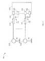
- FIG. 6is a block diagram illustrating a test configuration to measure self-capacitance using a single pin of a touch sensor device, according to an example embodiment.
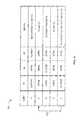
- FIG. 7is a table illustrating operations in testing the self-capacitance of the touch sensor device of FIG. 5 , according to an example embodiment.
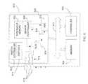
- FIG. 8is a block diagram of the touch sensor device of FIG. 5 , according to an example embodiment.
- FIG. 9is a flow diagram of a method for testing self-capacitance of the touch sensor, according to an example embodiment.
- the functions or algorithms described hereinmay be implemented in software or a combination of software and human implemented procedures in one embodiment.
- the softwaremay consist of computer executable instructions stored on computer readable media such as memory or other type of storage devices. Further, such functions correspond to modules, which are software, hardware, firmware or any combination thereof. Multiple functions may be performed in one or more modules as desired, and the embodiments described are merely examples.
- the softwaremay be executed on a Digital Signal Processor (DSP), Application Specific Integrated Circuit (ASIC), microprocessor, microcontroller, virtual controller system, or other type of processor operating on a computer system, such as a personal computer, server or other computer system.
- DSPDigital Signal Processor
- ASICApplication Specific Integrated Circuit
- Touchscreen displays and user interfacesmay be implemented in various configurations, and may include one or more conductive layers.
- the following discussionrelates to methods for testing a device having an internal capacitance, such as a mutual capacitance sensor device, having a driving layer and a sensing layer. These testing methods use the electrical characteristics and behavior of a capacitive sensor to provide a simplified test configuration and procedure. By taking advantage of the internal structure of a touch sensor device, these test methods may reduce reliance on external testing components used in previous test configurations.
- testing methods and apparatuses disclosed hereinare described with respect to a capacitive touch sensor, the test methods and apparatuses are applicable to other configurations, including single layer and multiple layer configurations of capacitive traces in a sensing device.
- the techniquesmay also be used to test capacitive keyboards or other devices using capacitive sensors.
- a touch sensor systemincludes at least one input port to receive an input signal from at least one electrode, the at least one electrode having a coupling capacitance.
- the touch sensor systemfurther includes an Analog to Digital Converter (ADC) to convert received continuous analog signals to discrete digital values, which may be used for processing and further computation.
- ADC output valueis proportional to the magnitude of the input voltage (or current).
- the ADCmay be implemented in a variety of ways as an electronic device, such as a direct conversion or flash circuit, a successive approximation converter, a ramp-compare converter, an integrating converter, a Sigma-Delta converter, and so forth.
- the digital outputmay be processed to apply a coding scheme to identify the corresponding analog input value.
- a touch sensor systemmay include a processing unit to perform operations in response to computer-readable instructions. The operations may incorporate the ADC output data.
- a capacitorsuch as a filtering capacitor, may be coupled to the ADC input. The capacitor may be used as a reference capacitor for detecting a touch on the touch sensor electrodes.
- a set of switchesis provided as a mechanism to couple charge to the reference capacitor.
- a first switchcouples a first reference voltage to a first input of multiple multiplexor (MUX) inputs, and a second switch couples a second reference voltage to the first input of the MUX, the MUX having an output coupled to an ADC input, wherein a MUX controller selects at least one of the MUX inputs to provide as an input to the ADC.
- MUXmultiple multiplexor
- a switch controllercontrols the first switch to apply the first reference voltage to the first input of the MUX, and controls the second switch to apply the second reference voltage to the first input of the MUX. Further, a sensor controller is coupled to receive a first digital value from the ADC output after application of the first reference voltage, to receive a second digital value after application of the second reference voltage, and to determine a change in the coupling capacitance of the at least one electrode as a function of the first and second digital values.
- FIG. 1illustrates an equivalent circuit representing a capacitive sensor system 100 having a capacitive sensor device 110 .
- the sensor system 100has an electrode 112 .
- the electrode 112may be responsive to a touch by a human hand or a device, such as a stylus.
- the human hand or devicehas a touch capacitance C t measured with respect to earth or ground.
- the electrode 112is coupled to sensor circuitry 114 within the sensor device 110 . As the electrode 112 is provided behind or below a dielectric panel (not shown), the user does not have direct galvanic connection to the touch sensor circuitry 114 .
- the sensor circuitry 114may be coupled to sensor firmware 116 controlling the sensor device 110 and interpreting the received touches at the electrode 112 .
- the structure and configuration of the sensor device 110has various self capacitances, such as capacitance C p1 which is measured at a point, P 1 , on a conductor between the electrode 112 and the sensor circuitry 114 .
- the capacitance C p1is the parasitic Input/Output (I/O) pin capacitance considered with respect to a reference ground.
- the electrode 112has an electrode capacitance C x with respect to a relative earth voltage, referred to as earth.
- a capacitance C p2is the wiring capacitance measured at a point P 2 , and is considered with respect to the reference ground.
- reference groundis considered the voltage between a given point and a local circuit return point, wherein the reference ground voltage may be any voltage value to which the voltages of other points are compared.
- the reference ground voltagemay be a specific voltage level applied to the sensor device 110 , or may be a reference plane within the sensor device 110 .
- earthis considered a free space return point, such as the potential difference measured from a user's finger to the earth or environment.
- a touch capacitance C texists between a human finger, or stylus, and earth. Between the relative ground and earth is a coupling capacitance C f .
- a test methodincludes the following assumptions: C x >>C p2 (1) C x >>C p1 (2) C f >>C x (3) C f >>C t (4) in evaluation of the capacitive sensor system 100 .
- FIG. 2illustrates a touch sensor configuration 200 including the capacitive sensor device 110 coupled to a touch sensor interface 206 .
- the touch sensor interface 206may include one or more electrodes, similar to the electrode 112 of FIG. 1 .
- a panel 202such as a dielectric panel overlays the touch sensor interface 206 .
- a display module 204is positioned below the touch sensor interface 206 , and is visible through the panel 202 and the touch sensor interface 206 .
- the capacitive sensor device 110receives inputs from the touch sensor interface, wherein the inputs may correspond to instructions, selections or other information provided by a user.
- touch sensor configurationsinclude different combinations of layers, as well as different implementations of the sensing device.
- the touch sensor interface 206is implemented as a capacitive sensor as used in a variety of touch sensor devices.
- FIG. 3illustrates a test configuration 300 for a sensor device 310 coupled to an electrode 312 .
- the electrode 312is position behind or below a dielectric panel, and thus does not make a galvanic connection with a user or stylus when a touch is made to the capacitive sensor system.
- the test configurationincludes a sampling capacitor C s that is positioned between two output ports, 318 and 320 , of the sensor device 310 .
- the sensor device 310has multiple switches, such as switch S 1 which is used to connect port 318 to an electrical ground, switch S 2 which is used to connect port 320 to a reference voltage V DD , and a switch S 3 which is used to connect port 320 to a reference ground.
- a table 400is provided in FIG. 4 illustrating operations for testing the sensor device 310 .
- the left-most columnprovides the step index, wherein steps are performed sequentially as indicated.
- the next columnidentifies the behavior or condition of switch S 1 , successive columns identify the behavior of condition of switches S 2 and S 3 , respectively.
- Notesare provided to explain the test procedure.
- the test proceduremeasures the capacitance C x using the sampling capacitance C s . This may be done by monitoring the behavior of the capacitance C x , in response to sequence of bursts or charge transfers.
- the burstsare provided using the switches. In this way, a burst switching sequence is applied to determine the capacitance C x .
- a burstis a sequence of charge transfers.
- step 1 of table 400the switch S 2 is open, while the switches S 1 and S 3 are closed. Connecting both sides of the sampling capacitor to relative ground effectively discharges any residual charge stored on the sampling capacitor, C s , as well as on the electrode's capacitance, C x . This is an initial condition of a measurement process, referred to as an acquisition phase.
- the switches S 1 , S 2 and S 3are open allowing the capacitors to float, and specifically allowing the sampling capacitor C s to float. This prevents cross-conduction within transistors of the sensor device 310 .
- step 3switch S 2 is closed, while the switches S 1 and S 3 remain open. Charge is driven through sampling capacitor C s to the capacitor C x . In this switching state, the same current flows through C s and C x so the charge transferred to each capacitor is effectively the same. Then at step 4, the switches S 1 , S 2 and S 3 are open allowing the sampling capacitor C s to float. As in step 2, allowing the capacitors to float prevents cross-conduction between transistors in the sensor device 310 . There is a settling time to allow the charge distribution to settle.
- step 5the switch S 1 is closed, while switches S 2 and S 3 remain open, which discharges the capacitor C x .
- Burst switchingallows transfer of charge to the capacitance C x through the capacitance Cs.
- the time to charge C xor the number of burst cycles used, is related to a ratio of capacitance for C x to C s .
- V(C s )increases in small steps.
- V(C s )reaches a predetermined voltage value, the acquisition phase ends. The time taken to complete the acquisition phase may be used to evaluate C x .
- the number of burst cyclesis the measurement used to evaluate the touch sensor 310 .
- each acquisitioncorresponds to the condition of the electrode 312 .
- the number of burst cycles for each acquisitioncorresponds approximately to a predetermined value.
- the number of burst cycles during the acquisition phasechanges and is different from the predetermined value, which indicates a touch to the electrode 312 .
- repeated acquisitionsare used to effectively measure the capacitance C x .
- the capacitance C tincreases and adds in parallel with capacitance C x (see FIG. 1 ).
- the increase in C tchanges the effective circuit such that C t and C x charge in parallel, resulting in a more rapid increase in the voltage V(C s ). Therefore, when a touch is applied to the electrode 312 fewer burst cycles are required to charge the capacitor C s in order to achieve V(C s ), and therefore in response to a touch event, the number of burst cycles is reduced and the burst time shortened.
- the change in the number of burst cycles during an acquisitionis proportional to C t .
- a calibration stageis used to determine the predetermined values for measurements. Once the reference value for the number of burst cycles is determined, this may be used as a threshold value to identify a potential touch. During an acquisition, if the number of burst cycles drops below the threshold value, a potential touch is identified.
- a process of Detection Integrationmay consider several successive acquisitions before identifying a touch event. The DI process detects a touch to a key or touch event for the touch sensor configuration 200 of FIG. 2 . The DI process assists in avoiding noise and other inadvertent effects which may be interpreted as a touch, but which are false reads.
- FIG. 5illustrates application of the test configuration 300 to a sensor device 510 having multiple ports, each coupled to an electrode 512 .
- the test configuration 500is illustrated, wherein the ports of the sensor device 510 are coupled to sampling capacitors 530 , 532 .
- the device sensor 510includes multiple ports, including at least ports 518 , 520 , 522 and 524 .
- the ports 518 and 522each are coupled to electrodes 512 , each having a line resistance 514 .
- a sampling capacitor C s 530is positioned between the port 518 and the port 520 .
- a sampling capacitor C s 532is positioned between port 522 and port 524 .
- the test configuration 500adds a sampling capacitor C s to each electrode 512 .
- test configurations 300 and 500require the addition of sampling capacitors for each electrode. As the number of electrodes increases, the number of sampling capacitors also increases.
- a testing methoduses relationships within a sensor device, or sensor circuitry, to measure the capacitance C x .
- FIG. 6illustrates a sensor device 610 having circuitry including an Analog to Digital Converter (ADC) 616 , multiple switches, S 1 and S 2 , and a switch controller 630 .
- the configuration 600eliminates the use of a sampling capacitor external to the sensor device 610 , such as used in the system of FIG. 3 .
- the touch sensor configuration 600instead uses a capacitor, C 1 , coupled to the ADC 616 , which is included in the sensor device 610 , thus reducing the circuitry required to implement the touch sensor configuration 600 .
- the switch controller 630selectively opens and closes the switches S 1 and S 2 .
- the switches S 1 and S 2may be controlled individually, wherein the switch 51 couples point P 1 to a reference voltage Vdd, and the switch S 2 couples the point P 1 to a reference ground.
- the reference voltage Vddis provided to the sensor device 610 , such as through a designated pin (not shown) or by processing a received voltage or electrical signal.
- the reference groundmay be provided to the sensor device 610 through a designated pin, or may be the voltage of a location within the sensor device 610 .
- a single electrode 612having corresponding capacitance C x is illustrated coupled to port 618 , however, it is to be appreciated that sensor device 610 may include any number of electrodes 612 and ports 618 .
- Port 618is then coupled to a multiplexer (MUX) 620 , wherein the connection has a line resistance 614 .
- the MUX 620has multiple inputs to receive inputs presented to ports, such as electrical signals, current or voltage received at port 618 from the electrode 612 .
- the MUX 620also has inputs coupled directly to the reference voltage Vdd, and to the reference ground which has an associated ground voltage.
- a control input 624is used to select one among the multiple inputs to the MUX 620 , wherein the selected one is supplied to the ADC 616 .
- the connection 622couples the output of MUX 620 to the input of the ADC 616 .
- the sensor device 610is further configured such that the switch S 1 enables connection of the port 618 to the reference voltage Vdd, and the switch S 2 enables connection of the port 618 to the reference ground.
- each input porthas a corresponding set of switches, such as S 1 and S 2 .
- An exampleis provided in FIG. 8 , wherein a bank of switches 811 is implemented having a switch controller 813 .
- the sensor device 610further has a capacitor, C 1 , coupled to the input to the ADC 616 .
- the capacitor C 1provides a filtering effect, to reduce or avoid fluctuations in voltage or signals provided from the output of MUX 620 to the input of the ADC 616 .
- the capacitor C 1may be used as a reference capacitor to identify electrical changes at the electrode 612 .
- the voltage Vdd/2may be provided to device sensor 610 , such as through a pin, or may be produced from the reference voltage Vdd.
- An example embodimentuses the capacitance C 1 , to identify changes in the capacitance C x , avoiding the need to add a sampling capacitor external to sensor device 610 . This reduces the need for external circuitry and provides a simplified configuration for touch sensing in touch sensor configuration 600 .
- the switches S 1 and S 2allow burst switching to measure changes corresponding to a touch to the electrode 612 . Such a method is described in the table 700 of FIG. 7 .
- the left-most columnprovides the step index, wherein steps are performed sequentially as indicated.
- the next columnidentifies the behavior or condition of switch S 1 , successive columns identify the behavior of switch S 2 and the control input, respectively. Notes are provided to explain the test procedure.
- the switches S 1 and S 2are open, while control 624 couples the reference ground as input to the MUX 620 . This grounds the capacitance C 1 to discharge any residual voltage.
- switch S 1is closed, while switch S 2 is open.
- the control 624couples Vdd as an input to the MUX 620 .
- the capacitor C 1is charged to a positive value.
- the voltage across the capacitor C 1is the difference of Vdd and Vdd/2, or Vdd/2.
- an input signal having a positive amplitudeis provided to the input to the MUX 620 at this step.
- switches S 1 and S 2are open, and the input to the MUX 620 is the input received at port 618 from the electrode 612 .
- a first measurementis made of the voltage V(C 1 ), which represents a positive voltage. The measurement is made by the ADC 616 .
- switch S 1remains open while switch S 2 is closed.
- the control 624couples reference ground as an input to MUX 620 . This serves to charge the capacitor C 1 to a negative value.
- the voltage across the capacitor C 1is the difference of the ground voltage and Vdd/2, which is a negative voltage in comparison to Vdd/2.
- an input signalis applied to the input to the MUX 620 which has an opposite polarity to the input signal applied at step 2, such as to use two opposing pulses.
- the opposing pulsesact to reject low frequency noise such as mains interference from a power supply. In other words, if mains interference is present in the reference voltage Vdd, such interference will not be present in the ground reference voltage GND.
- the interferencewill be present in one measurement, but not in the other measurement.
- the mains interferencemay be removed.
- switches S 1 and S 2are open, and the input to the MUX 620 is the input received at port 618 from the electrode 612 .
- a second measurementis made of the voltage V(C 1 ), which in this situation represents a negative voltage. The measurement is made by the ADC 616 .
- Interferencemay include the frequency of the processing unit (not shown), referred to as the mains hum.
- the low frequency interferenceexhibits as a same value in the measurements, while the measured value of the ADC 616 reflects a positive and an inverted signal. This allows cancellation of the interference.
- the measurements described in table 700 of FIG. 7are based on the sharing of charge between the capacitance C x and the capacitance C 1 .
- FIG. 8illustrates a processing unit 810 , including a sensing circuitry 820 to process signals received from electrodes (not shown) coupled to ports 818 .
- the processing unit 810includes a controller 802 and a memory 804 coupled to the sensing circuitry 820 through communication bus 812 .
- a threshold memory 832is included within the sensing circuitry 820 to store threshold values and information to identify capacitance changes. It is appreciated that various embodiments may have additional modules, circuitry, software, firmware and functionality, coupled directly or through buses or circuitry.
- the processing unit 810may be part of an application, such as illustrated in touch sensor configuration 200 of FIG. 2 .
- the sensing circuitry 820includes an ADC 822 which outputs a digital value corresponding to a received analog value.
- the ports 818are each coupled to inputs of a MUX 824 , and each has a line resistance 814 .
- the sensor controller 830may provide a control signal to the MUX 824 to select one of the inputs of the MUX 824 to output to ADC 822 .
- Configured between the MUX 824 and the ADC 822is a reference circuit 826 , which in some embodiments includes a reference capacitor.
- the reference circuit 826is used to identify a change in electrical behavior or characteristics at the electrodes. When a touch is received at an electrode, the capacitance of the electrode changes due to the proximity of the touching mechanism, such as a human finger, a stylus or other device, to the electrode.
- the sensor controller 830may further control operation of the ADC 822 .
- a reference capacitormay be a variable capacitor used to adjust the sensitivity of the touch sensor.
- a bank of switches 811is coupled to the input ports 818 , wherein each of the input ports has an associated switch pair, e.g. S 1 and S 2 , within the bank of switches 811 .
- Other arrangements and configurationsmay be implemented so as to provide a switching configuration as in FIG. 6 for each port 818 .
- each pin 818has a switch S 1 coupled to reference voltage Vdd and a switch S 2 coupled to a relative ground, GND. Operations for testing each of the ports 818 is performed similarly to the testing of port 618 .
- the bank of switches 811is controlled by a switch controller 813 , which controls each of the switch pairs, S 1 and S 2 , within the bank of switches 811 .
- FIG. 9illustrates a method 900 starting with an operation 902 to calibrate the touch sensor system, such as the touch sensor configuration 600 of FIG. 6 .
- the calibration phasedetermines threshold values for a reference capacitor, such that the touch sensor system is able to distinguish between an ambient condition, where no touch is applied to the touch sensor system, and a condition when a touch is applied.
- Operation 904serves to store the threshold values in a memory storage device.
- Processing of an acquisition phasefirst discharges 906 the reference capacitor, such as capacitor C 1 of FIG. 6 .
- a positive voltageis applied to the reference capacitor (operation 908 ) and a signal received from the electrode is measured (operation 910 ).
- the process 900continues, and a negative voltage signal is applied to the reference capacitor (operation 912 ), and a signal received from the electrode is measured (operation 914 ).
- a comparison and evaluation of the measurementsis made to eliminate interference from the signals and identify a touch event.
- processingreturns to operation 906 to begin a next acquisition.
- the electrodeis in an ambient state and no touch is detected.
- processingcontinues to determine if the DI is completed (decisional operation 922 ).
- the touch detectionis confirmed and processing continues to perform the action indicated by the touch (operation 924 ). For example, when a user applies a touch to the electrode in order to select a key or button on the touch sensor device, the function associated with that key is implemented when the touch is detected.
- processingAfter detection of the touch, processing returns to operation 906 and a next acquisition begins.
- processingreturns to operation 906 to continue the current acquisition. In other words, an acquisition identifying a touch continues until the DI is complete, or a measurement is received that does not satisfy the threshold value.
- the DIis implemented to avoid spurious measurements, or measurements which are not results of a touch at the electrode but rather are due to other operational conditions.
- the present discussionconsiders a method for measuring capacitance in a sensor device without additional circuitry and devices applied external to the sensor device, such as by using an output pin of the sensor device.
- the measurement methods describeduse an internal capacitor, or other electrical component, as a reference to identify a touch applied to a touch point or electrode coupled to the touch sensor.
- the touch sensorapplies charges to the reference capacitor and measures a signal received from an electrode. The measurements are used to identify a touch to the electrode.
- the methods and apparatus describedmay be used in conjunction with an appliance having a human-machine interface. It is also possible to provide a sensor, similar to those described above, which is provided separately from the device or appliance which it controls, for example to provide an upgrade to a pre-existing appliance. It is also possible to provide a generic sensor which may be configured to operate on a range of different appliances.
Landscapes
- Physics & Mathematics (AREA)
- General Physics & Mathematics (AREA)
- Measurement Of Resistance Or Impedance (AREA)
- Electronic Switches (AREA)
- Position Input By Displaying (AREA)
Abstract
Description
Cx>>Cp2 (1)
Cx>>Cp1 (2)
Cf>>Cx (3)
Cf>>Ct (4)
in evaluation of the
V(Cs)=(Cx*Vdd)/(Cs+Cx) (5)
wherein V(Cs) is the voltage across the sampling capacitor Cs. During each burst cycle, V(Cs) increases in small steps. When V(Cs) reaches a predetermined voltage value, the acquisition phase ends. The time taken to complete the acquisition phase may be used to evaluate Cx.
Claims (16)
Priority Applications (6)
| Application Number | Priority Date | Filing Date | Title |
|---|---|---|---|
| US12/567,473US8552994B2 (en) | 2009-09-25 | 2009-09-25 | Method and apparatus to measure self-capacitance using a single pin |
| CN201010290809.4ACN102033166B (en) | 2009-09-25 | 2010-09-21 | Method and apparatus to measure self-capacitance using single pin |
| TW099132492ATWI506513B (en) | 2009-09-25 | 2010-09-24 | Method and apparatus to measure self-capacitance using a single pin |
| DE102010041464ADE102010041464A1 (en) | 2009-09-25 | 2010-09-27 | Method and apparatus for measuring self-capacitance using a single pin |
| US14/047,774US10126340B2 (en) | 2009-09-25 | 2013-10-07 | Method and apparatus to measure self-capacitance using a single pin |
| US16/188,588US20190086457A1 (en) | 2009-09-25 | 2018-11-13 | Method and apparatus to measure self-capacitance using a single pin |
Applications Claiming Priority (1)
| Application Number | Priority Date | Filing Date | Title |
|---|---|---|---|
| US12/567,473US8552994B2 (en) | 2009-09-25 | 2009-09-25 | Method and apparatus to measure self-capacitance using a single pin |
Related Child Applications (1)
| Application Number | Title | Priority Date | Filing Date |
|---|---|---|---|
| US14/047,774ContinuationUS10126340B2 (en) | 2009-09-25 | 2013-10-07 | Method and apparatus to measure self-capacitance using a single pin |
Publications (2)
| Publication Number | Publication Date |
|---|---|
| US20110073383A1 US20110073383A1 (en) | 2011-03-31 |
| US8552994B2true US8552994B2 (en) | 2013-10-08 |
Family
ID=43734758
Family Applications (3)
| Application Number | Title | Priority Date | Filing Date |
|---|---|---|---|
| US12/567,473Active2031-11-08US8552994B2 (en) | 2009-09-25 | 2009-09-25 | Method and apparatus to measure self-capacitance using a single pin |
| US14/047,774Active2032-03-06US10126340B2 (en) | 2009-09-25 | 2013-10-07 | Method and apparatus to measure self-capacitance using a single pin |
| US16/188,588AbandonedUS20190086457A1 (en) | 2009-09-25 | 2018-11-13 | Method and apparatus to measure self-capacitance using a single pin |
Family Applications After (2)
| Application Number | Title | Priority Date | Filing Date |
|---|---|---|---|
| US14/047,774Active2032-03-06US10126340B2 (en) | 2009-09-25 | 2013-10-07 | Method and apparatus to measure self-capacitance using a single pin |
| US16/188,588AbandonedUS20190086457A1 (en) | 2009-09-25 | 2018-11-13 | Method and apparatus to measure self-capacitance using a single pin |
Country Status (4)
| Country | Link |
|---|---|
| US (3) | US8552994B2 (en) |
| CN (1) | CN102033166B (en) |
| DE (1) | DE102010041464A1 (en) |
| TW (1) | TWI506513B (en) |
Cited By (13)
| Publication number | Priority date | Publication date | Assignee | Title |
|---|---|---|---|---|
| US20090295409A1 (en)* | 2008-05-27 | 2009-12-03 | Alex Irkliy | Capacitive voltage divider touch sensor |
| US20130222341A1 (en)* | 2010-09-30 | 2013-08-29 | Jiangsu Huitong Group Co., Ltd | Touch recognition method, touch key structure and touch device |
| WO2015139113A1 (en)* | 2014-03-17 | 2015-09-24 | Magna Closures Inc. | Method and system for driving a capacitive sensor |
| US10101862B2 (en) | 2014-05-16 | 2018-10-16 | Leopold Kotsai GmbH & Co. KG | Method for measuring a capacitance value |
| US10788941B2 (en) | 2016-09-17 | 2020-09-29 | Kostal Automobil Elektrik Gmbh & Co. Kg | Method for detecting contact on a capacitive sensor element |
| US10795488B2 (en) | 2015-02-02 | 2020-10-06 | Apple Inc. | Flexible self-capacitance and mutual capacitance touch sensing system architecture |
| US10809847B2 (en) | 2013-02-13 | 2020-10-20 | Apple Inc. | In-cell touch for LED |
| US10852894B2 (en) | 2016-07-29 | 2020-12-01 | Apple Inc. | Touch sensor panel with multi-power domain chip configuration |
| US10936120B2 (en) | 2014-05-22 | 2021-03-02 | Apple Inc. | Panel bootstraping architectures for in-cell self-capacitance |
| US11079880B2 (en) | 2015-07-01 | 2021-08-03 | Kostal Automobil Elektrik Gmbh & Co. Kg | Method for measuring a capacitance value |
| US11086444B2 (en) | 2013-12-13 | 2021-08-10 | Apple Inc. | Integrated touch and display architectures for self-capacitive touch sensors |
| US11662867B1 (en) | 2020-05-30 | 2023-05-30 | Apple Inc. | Hover detection on a touch sensor panel |
| US12092496B2 (en) | 2020-05-12 | 2024-09-17 | Nxp Usa, Inc. | Capacitive sensing |
Families Citing this family (21)
| Publication number | Priority date | Publication date | Assignee | Title |
|---|---|---|---|---|
| CN102193693B (en)* | 2010-03-17 | 2014-03-19 | 群康科技(深圳)有限公司 | Touch panel and differential identification method thereof |
| US20120169659A1 (en)* | 2010-08-29 | 2012-07-05 | Welland David R | Apparatus for capacitance sensor with interference rejection and associated methods |
| US20120050206A1 (en)* | 2010-08-29 | 2012-03-01 | David Welland | Multi-touch resolve mutual capacitance sensor |
| US8941393B2 (en)* | 2011-01-14 | 2015-01-27 | Cypress Semiconductor Corporation | Detection of a conductive object during an initialization process of a touch-sensing device |
| US20120306805A1 (en)* | 2011-05-31 | 2012-12-06 | Idt Technology Limited | Hand-worn device with finger activation and control mechanisms |
| US8416117B2 (en) | 2011-08-11 | 2013-04-09 | Atmel Corporation | Analog to digital converter with dual integrating capacitor systems |
| FR2985049B1 (en)* | 2011-12-22 | 2014-01-31 | Nanotec Solution | CAPACITIVE MEASURING DEVICE WITH SWITCHED ELECTRODES FOR TOUCHLESS CONTACTLESS INTERFACES |
| US9013425B2 (en) | 2012-02-23 | 2015-04-21 | Cypress Semiconductor Corporation | Method and apparatus for data transmission via capacitance sensing device |
| KR101343821B1 (en)* | 2012-03-06 | 2013-12-20 | 주식회사 리딩유아이 | Capacitance measuring circuit of a touch sensor and capacitance type touch panel |
| CN103150077B (en)* | 2013-03-29 | 2020-01-03 | 苏州瀚瑞微电子有限公司 | Circuit arrangement |
| CN106875979B (en)* | 2015-12-11 | 2020-04-14 | 展讯通信(上海)有限公司 | Method and device for measuring pin capacitance of IP core of memory |
| DE102016003779A1 (en) | 2016-03-26 | 2017-09-28 | Leopold Kostal Gmbh & Co. Kg | Method for detecting a contact of a capacitive sensor element |
| US9823798B2 (en)* | 2016-04-08 | 2017-11-21 | Nxp Usa, Inc. | Capacitive sensor device and method of operation |
| DE102017002482A1 (en) | 2017-03-15 | 2018-09-20 | Leopold Kostal Gmbh & Co. Kg | A method for determining a time of contact of a capacitive sensor element |
| WO2018212587A1 (en) | 2017-05-18 | 2018-11-22 | Samsung Electronics Co., Ltd. | X-ray input apparatus, x-ray imaging apparatus having the same, and method of controlling the x-ray input apparatus |
| AU2018368707B2 (en) | 2017-11-16 | 2024-03-07 | Bruin Biometrics, Llc | Strategic treatment of pressure ulcer using sub-epidermal moisture values |
| AU2019217995B2 (en) | 2018-02-09 | 2024-11-14 | Bruin Biometrics, Llc | Detection of tissue damage |
| US10521045B2 (en)* | 2018-02-14 | 2019-12-31 | Microchip Technology Incorporated | Reference noise rejection improvement based on sample and hold circuitry |
| FR3107129B1 (en) | 2020-02-10 | 2022-02-18 | St Microelectronics Sa | Device and method for detecting tactile contact |
| DE102020001919A1 (en) | 2020-03-25 | 2021-09-30 | Kostal Automobil Elektrik Gmbh & Co. Kg | Method for changing a status of a one- or two-dimensional, touch-sensitive array of capacitive sensor elements |
| IL296904A (en)* | 2020-04-03 | 2022-12-01 | Bruin Biometrics Llc | Biocapacitance sensor |
Citations (18)
| Publication number | Priority date | Publication date | Assignee | Title |
|---|---|---|---|---|
| US6088024A (en)* | 1997-06-13 | 2000-07-11 | Nec Corporation | Touch panel and method for detecting a pressed position on a touch panel |
| US6466036B1 (en)* | 1998-11-25 | 2002-10-15 | Harald Philipp | Charge transfer capacitance measurement circuit |
| US20090295754A1 (en)* | 2008-06-03 | 2009-12-03 | Himax Technologies Limited | Touch panel |
| US20090315854A1 (en) | 2008-06-18 | 2009-12-24 | Epson Imaging Devices Corporation | Capacitance type input device and display device with input function |
| US7663607B2 (en) | 2004-05-06 | 2010-02-16 | Apple Inc. | Multipoint touchscreen |
| US20100134391A1 (en)* | 2008-12-02 | 2010-06-03 | Hui-Min Wang | Standby Circuit and Method for a Display Device |
| US7875814B2 (en) | 2005-07-21 | 2011-01-25 | Tpo Displays Corp. | Electromagnetic digitizer sensor array structure |
| US7920129B2 (en) | 2007-01-03 | 2011-04-05 | Apple Inc. | Double-sided touch-sensitive panel with shield and drive combined layer |
| US8031174B2 (en) | 2007-01-03 | 2011-10-04 | Apple Inc. | Multi-touch surface stackup arrangement |
| US8031094B2 (en) | 2009-09-11 | 2011-10-04 | Apple Inc. | Touch controller with improved analog front end |
| US8040326B2 (en) | 2007-06-13 | 2011-10-18 | Apple Inc. | Integrated in-plane switching display and touch sensor |
| US8049732B2 (en) | 2007-01-03 | 2011-11-01 | Apple Inc. | Front-end signal compensation |
| US8179381B2 (en) | 2008-02-28 | 2012-05-15 | 3M Innovative Properties Company | Touch screen sensor |
| WO2012129247A2 (en) | 2011-03-21 | 2012-09-27 | Apple Inc. | Electronic devices with flexible displays |
| US20120242588A1 (en) | 2011-03-21 | 2012-09-27 | Myers Scott A | Electronic devices with concave displays |
| US20120242592A1 (en) | 2011-03-21 | 2012-09-27 | Rothkopf Fletcher R | Electronic devices with flexible displays |
| US20120243719A1 (en) | 2011-03-21 | 2012-09-27 | Franklin Jeremy C | Display-Based Speaker Structures for Electronic Devices |
| US20120243151A1 (en) | 2011-03-21 | 2012-09-27 | Stephen Brian Lynch | Electronic Devices With Convex Displays |
Family Cites Families (4)
| Publication number | Priority date | Publication date | Assignee | Title |
|---|---|---|---|---|
| US4039940A (en)* | 1976-07-30 | 1977-08-02 | General Electric Company | Capacitance sensor |
| US6452531B1 (en)* | 1999-08-27 | 2002-09-17 | Analog Devices, Inc. | Jitter and load insensitive charge transfer |
| KR100510499B1 (en)* | 2002-12-04 | 2005-08-26 | 삼성전자주식회사 | Scaler having electro-magnetic interference reduction scheme for driving Liquid Crystal Display |
| US8237456B2 (en)* | 2009-03-02 | 2012-08-07 | Atmel Corporation | Capacitive sensing |
- 2009
- 2009-09-25USUS12/567,473patent/US8552994B2/enactiveActive
- 2010
- 2010-09-21CNCN201010290809.4Apatent/CN102033166B/enactiveActive
- 2010-09-24TWTW099132492Apatent/TWI506513B/enactive
- 2010-09-27DEDE102010041464Apatent/DE102010041464A1/enactivePending
- 2013
- 2013-10-07USUS14/047,774patent/US10126340B2/enactiveActive
- 2018
- 2018-11-13USUS16/188,588patent/US20190086457A1/ennot_activeAbandoned
Patent Citations (19)
| Publication number | Priority date | Publication date | Assignee | Title |
|---|---|---|---|---|
| US6088024A (en)* | 1997-06-13 | 2000-07-11 | Nec Corporation | Touch panel and method for detecting a pressed position on a touch panel |
| US6466036B1 (en)* | 1998-11-25 | 2002-10-15 | Harald Philipp | Charge transfer capacitance measurement circuit |
| US7663607B2 (en) | 2004-05-06 | 2010-02-16 | Apple Inc. | Multipoint touchscreen |
| US7875814B2 (en) | 2005-07-21 | 2011-01-25 | Tpo Displays Corp. | Electromagnetic digitizer sensor array structure |
| US8031174B2 (en) | 2007-01-03 | 2011-10-04 | Apple Inc. | Multi-touch surface stackup arrangement |
| US8049732B2 (en) | 2007-01-03 | 2011-11-01 | Apple Inc. | Front-end signal compensation |
| US7920129B2 (en) | 2007-01-03 | 2011-04-05 | Apple Inc. | Double-sided touch-sensitive panel with shield and drive combined layer |
| US8040326B2 (en) | 2007-06-13 | 2011-10-18 | Apple Inc. | Integrated in-plane switching display and touch sensor |
| US8179381B2 (en) | 2008-02-28 | 2012-05-15 | 3M Innovative Properties Company | Touch screen sensor |
| US20090295754A1 (en)* | 2008-06-03 | 2009-12-03 | Himax Technologies Limited | Touch panel |
| US20090315854A1 (en) | 2008-06-18 | 2009-12-24 | Epson Imaging Devices Corporation | Capacitance type input device and display device with input function |
| US8049696B2 (en)* | 2008-12-02 | 2011-11-01 | Himax Media Solutions, Inc. | Standby circuit and method for a display device |
| US20100134391A1 (en)* | 2008-12-02 | 2010-06-03 | Hui-Min Wang | Standby Circuit and Method for a Display Device |
| US8031094B2 (en) | 2009-09-11 | 2011-10-04 | Apple Inc. | Touch controller with improved analog front end |
| WO2012129247A2 (en) | 2011-03-21 | 2012-09-27 | Apple Inc. | Electronic devices with flexible displays |
| US20120242588A1 (en) | 2011-03-21 | 2012-09-27 | Myers Scott A | Electronic devices with concave displays |
| US20120242592A1 (en) | 2011-03-21 | 2012-09-27 | Rothkopf Fletcher R | Electronic devices with flexible displays |
| US20120243719A1 (en) | 2011-03-21 | 2012-09-27 | Franklin Jeremy C | Display-Based Speaker Structures for Electronic Devices |
| US20120243151A1 (en) | 2011-03-21 | 2012-09-27 | Stephen Brian Lynch | Electronic Devices With Convex Displays |
Non-Patent Citations (4)
| Title |
|---|
| "Capacitive Touch Using Only an ADC ("CVD")", Microchip Technologies, Inc., Datasheet, AN1298, (Mar. 26, 2009), 4 pgs. |
| U.S. Appl. No. 61/454,894, filed Mar. 21, 2011, Rothkopf. |
| U.S. Appl. No. 61/454,936, filed Mar. 21, 2011, Myers. |
| U.S. Appl. No. 61/454,950, filed Mar. 21, 2011, Lynch. |
Cited By (17)
| Publication number | Priority date | Publication date | Assignee | Title |
|---|---|---|---|---|
| US9367179B2 (en)* | 2008-05-27 | 2016-06-14 | Microchip Technology Incorporated | Capacitive voltage divider touch sensor |
| US20090295409A1 (en)* | 2008-05-27 | 2009-12-03 | Alex Irkliy | Capacitive voltage divider touch sensor |
| US20130222341A1 (en)* | 2010-09-30 | 2013-08-29 | Jiangsu Huitong Group Co., Ltd | Touch recognition method, touch key structure and touch device |
| US9063626B2 (en)* | 2010-09-30 | 2015-06-23 | Jiangsu Huitong Group Co., Ltd | Touch recognition method, touch key structure and touch device |
| US10809847B2 (en) | 2013-02-13 | 2020-10-20 | Apple Inc. | In-cell touch for LED |
| US11086444B2 (en) | 2013-12-13 | 2021-08-10 | Apple Inc. | Integrated touch and display architectures for self-capacitive touch sensors |
| WO2015139113A1 (en)* | 2014-03-17 | 2015-09-24 | Magna Closures Inc. | Method and system for driving a capacitive sensor |
| US10101862B2 (en) | 2014-05-16 | 2018-10-16 | Leopold Kotsai GmbH & Co. KG | Method for measuring a capacitance value |
| US10936120B2 (en) | 2014-05-22 | 2021-03-02 | Apple Inc. | Panel bootstraping architectures for in-cell self-capacitance |
| US10795488B2 (en) | 2015-02-02 | 2020-10-06 | Apple Inc. | Flexible self-capacitance and mutual capacitance touch sensing system architecture |
| US11353985B2 (en) | 2015-02-02 | 2022-06-07 | Apple Inc. | Flexible self-capacitance and mutual capacitance touch sensing system architecture |
| US12014003B2 (en) | 2015-02-02 | 2024-06-18 | Apple Inc. | Flexible self-capacitance and mutual capacitance touch sensing system architecture |
| US11079880B2 (en) | 2015-07-01 | 2021-08-03 | Kostal Automobil Elektrik Gmbh & Co. Kg | Method for measuring a capacitance value |
| US10852894B2 (en) | 2016-07-29 | 2020-12-01 | Apple Inc. | Touch sensor panel with multi-power domain chip configuration |
| US10788941B2 (en) | 2016-09-17 | 2020-09-29 | Kostal Automobil Elektrik Gmbh & Co. Kg | Method for detecting contact on a capacitive sensor element |
| US12092496B2 (en) | 2020-05-12 | 2024-09-17 | Nxp Usa, Inc. | Capacitive sensing |
| US11662867B1 (en) | 2020-05-30 | 2023-05-30 | Apple Inc. | Hover detection on a touch sensor panel |
Also Published As
| Publication number | Publication date |
|---|---|
| CN102033166B (en) | 2014-10-15 |
| US20140039819A1 (en) | 2014-02-06 |
| DE102010041464A1 (en) | 2011-04-14 |
| TW201133321A (en) | 2011-10-01 |
| US20190086457A1 (en) | 2019-03-21 |
| US20110073383A1 (en) | 2011-03-31 |
| US10126340B2 (en) | 2018-11-13 |
| CN102033166A (en) | 2011-04-27 |
| TWI506513B (en) | 2015-11-01 |
Similar Documents
| Publication | Publication Date | Title |
|---|---|---|
| US8552994B2 (en) | Method and apparatus to measure self-capacitance using a single pin | |
| US8054090B2 (en) | Noise handling in capacitive touch sensors | |
| US9367179B2 (en) | Capacitive voltage divider touch sensor | |
| US8552995B2 (en) | Sensor and method of sensing | |
| KR102325699B1 (en) | Analog elimination of ungrounded conductive objects in capacitive sensing | |
| CN102564474B (en) | Sampling Circuity | |
| US7986153B2 (en) | Method and apparatus for sensing | |
| US20110156724A1 (en) | Capacitance measurement systems and methods | |
| JP5191769B2 (en) | Capacity detection apparatus and method | |
| US8432170B1 (en) | Integrated capacitance model circuit | |
| US20130106779A1 (en) | Noise compensation techniques for capacitive touch screen systems | |
| CN111108465B (en) | Method for combining self-capacitance and mutual capacitance sensing | |
| WO2012096781A2 (en) | Detection of a conductive object during an initialization process of a touch-sensing device | |
| US20130063388A1 (en) | Capacitive touch screen controller implementing a sensing method for improved noise immunity | |
| CN114355056A (en) | Capacitance measuring circuit, capacitance measuring system, touch device and electronic equipment | |
| US20190369803A1 (en) | Method of detecting liquid on a capacitive touchpad and controller thereof | |
| US9500686B1 (en) | Capacitance measurement system and methods | |
| TW200917130A (en) | Method of current source for control and compensation touch sensing capacitor detector and apparatus thereof | |
| TWI400456B (en) | Used in capacitive touch buttons and proximity sensing sensing circuits and methods | |
| EP2722988A1 (en) | A method of the touch detection for capacitive touch sensors | |
| EP2722985B1 (en) | Method of differential measurement of voltage levels of capacitive change. | |
| US20240310420A1 (en) | Interference-insensitive determination of a capacitance | |
| JP2017021635A (en) | Electrostatic detection device |
Legal Events
| Date | Code | Title | Description |
|---|---|---|---|
| AS | Assignment | Owner name:QRG LIMITED, UNITED KINGDOM Free format text:ASSIGNMENT OF ASSIGNORS INTEREST;ASSIGNOR:SIMMONS, MARTIN JOHN;REEL/FRAME:023651/0066 Effective date:20091126 | |
| AS | Assignment | Owner name:ATMEL CORPORATION, CALIFORNIA Free format text:ASSIGNMENT OF ASSIGNORS INTEREST;ASSIGNOR:QRG LIMITED;REEL/FRAME:023656/0538 Effective date:20091211 | |
| STCF | Information on status: patent grant | Free format text:PATENTED CASE | |
| AS | Assignment | Owner name:MORGAN STANLEY SENIOR FUNDING, INC. AS ADMINISTRATIVE AGENT, NEW YORK Free format text:PATENT SECURITY AGREEMENT;ASSIGNOR:ATMEL CORPORATION;REEL/FRAME:031912/0173 Effective date:20131206 Owner name:MORGAN STANLEY SENIOR FUNDING, INC. AS ADMINISTRAT Free format text:PATENT SECURITY AGREEMENT;ASSIGNOR:ATMEL CORPORATION;REEL/FRAME:031912/0173 Effective date:20131206 | |
| AS | Assignment | Owner name:ATMEL CORPORATION, CALIFORNIA Free format text:TERMINATION AND RELEASE OF SECURITY INTEREST IN PATENT COLLATERAL;ASSIGNOR:MORGAN STANLEY SENIOR FUNDING, INC.;REEL/FRAME:038376/0001 Effective date:20160404 | |
| AS | Assignment | Owner name:JPMORGAN CHASE BANK, N.A., AS ADMINISTRATIVE AGENT, ILLINOIS Free format text:SECURITY INTEREST;ASSIGNOR:ATMEL CORPORATION;REEL/FRAME:041715/0747 Effective date:20170208 Owner name:JPMORGAN CHASE BANK, N.A., AS ADMINISTRATIVE AGENT Free format text:SECURITY INTEREST;ASSIGNOR:ATMEL CORPORATION;REEL/FRAME:041715/0747 Effective date:20170208 | |
| FPAY | Fee payment | Year of fee payment:4 | |
| AS | Assignment | Owner name:JPMORGAN CHASE BANK, N.A., AS ADMINISTRATIVE AGENT, ILLINOIS Free format text:SECURITY INTEREST;ASSIGNORS:MICROCHIP TECHNOLOGY INCORPORATED;SILICON STORAGE TECHNOLOGY, INC.;ATMEL CORPORATION;AND OTHERS;REEL/FRAME:046426/0001 Effective date:20180529 Owner name:JPMORGAN CHASE BANK, N.A., AS ADMINISTRATIVE AGENT Free format text:SECURITY INTEREST;ASSIGNORS:MICROCHIP TECHNOLOGY INCORPORATED;SILICON STORAGE TECHNOLOGY, INC.;ATMEL CORPORATION;AND OTHERS;REEL/FRAME:046426/0001 Effective date:20180529 | |
| AS | Assignment | Owner name:WELLS FARGO BANK, NATIONAL ASSOCIATION, AS NOTES COLLATERAL AGENT, CALIFORNIA Free format text:SECURITY INTEREST;ASSIGNORS:MICROCHIP TECHNOLOGY INCORPORATED;SILICON STORAGE TECHNOLOGY, INC.;ATMEL CORPORATION;AND OTHERS;REEL/FRAME:047103/0206 Effective date:20180914 Owner name:WELLS FARGO BANK, NATIONAL ASSOCIATION, AS NOTES C Free format text:SECURITY INTEREST;ASSIGNORS:MICROCHIP TECHNOLOGY INCORPORATED;SILICON STORAGE TECHNOLOGY, INC.;ATMEL CORPORATION;AND OTHERS;REEL/FRAME:047103/0206 Effective date:20180914 | |
| AS | Assignment | Owner name:JPMORGAN CHASE BANK, N.A., AS ADMINISTRATIVE AGENT, DELAWARE Free format text:SECURITY INTEREST;ASSIGNORS:MICROCHIP TECHNOLOGY INC.;SILICON STORAGE TECHNOLOGY, INC.;ATMEL CORPORATION;AND OTHERS;REEL/FRAME:053311/0305 Effective date:20200327 | |
| AS | Assignment | Owner name:MICROSEMI CORPORATION, CALIFORNIA Free format text:RELEASE BY SECURED PARTY;ASSIGNOR:JPMORGAN CHASE BANK, N.A, AS ADMINISTRATIVE AGENT;REEL/FRAME:053466/0011 Effective date:20200529 Owner name:ATMEL CORPORATION, ARIZONA Free format text:RELEASE BY SECURED PARTY;ASSIGNOR:JPMORGAN CHASE BANK, N.A, AS ADMINISTRATIVE AGENT;REEL/FRAME:053466/0011 Effective date:20200529 Owner name:MICROSEMI STORAGE SOLUTIONS, INC., ARIZONA Free format text:RELEASE BY SECURED PARTY;ASSIGNOR:JPMORGAN CHASE BANK, N.A, AS ADMINISTRATIVE AGENT;REEL/FRAME:053466/0011 Effective date:20200529 Owner name:MICROCHIP TECHNOLOGY INC., ARIZONA Free format text:RELEASE BY SECURED PARTY;ASSIGNOR:JPMORGAN CHASE BANK, N.A, AS ADMINISTRATIVE AGENT;REEL/FRAME:053466/0011 Effective date:20200529 Owner name:SILICON STORAGE TECHNOLOGY, INC., ARIZONA Free format text:RELEASE BY SECURED PARTY;ASSIGNOR:JPMORGAN CHASE BANK, N.A, AS ADMINISTRATIVE AGENT;REEL/FRAME:053466/0011 Effective date:20200529 | |
| AS | Assignment | Owner name:WELLS FARGO BANK, NATIONAL ASSOCIATION, MINNESOTA Free format text:SECURITY INTEREST;ASSIGNORS:MICROCHIP TECHNOLOGY INC.;SILICON STORAGE TECHNOLOGY, INC.;ATMEL CORPORATION;AND OTHERS;REEL/FRAME:053468/0705 Effective date:20200529 | |
| AS | Assignment | Owner name:WELLS FARGO BANK, NATIONAL ASSOCIATION, AS COLLATERAL AGENT, MINNESOTA Free format text:SECURITY INTEREST;ASSIGNORS:MICROCHIP TECHNOLOGY INCORPORATED;SILICON STORAGE TECHNOLOGY, INC.;ATMEL CORPORATION;AND OTHERS;REEL/FRAME:055671/0612 Effective date:20201217 | |
| MAFP | Maintenance fee payment | Free format text:PAYMENT OF MAINTENANCE FEE, 8TH YEAR, LARGE ENTITY (ORIGINAL EVENT CODE: M1552); ENTITY STATUS OF PATENT OWNER: LARGE ENTITY Year of fee payment:8 | |
| AS | Assignment | Owner name:WELLS FARGO BANK, NATIONAL ASSOCIATION, AS NOTES COLLATERAL AGENT, MINNESOTA Free format text:SECURITY INTEREST;ASSIGNORS:MICROCHIP TECHNOLOGY INCORPORATED;SILICON STORAGE TECHNOLOGY, INC.;ATMEL CORPORATION;AND OTHERS;REEL/FRAME:057935/0474 Effective date:20210528 | |
| AS | Assignment | Owner name:MICROSEMI STORAGE SOLUTIONS, INC., ARIZONA Free format text:RELEASE BY SECURED PARTY;ASSIGNOR:JPMORGAN CHASE BANK, N.A., AS ADMINISTRATIVE AGENT;REEL/FRAME:059333/0222 Effective date:20220218 Owner name:MICROSEMI CORPORATION, ARIZONA Free format text:RELEASE BY SECURED PARTY;ASSIGNOR:JPMORGAN CHASE BANK, N.A., AS ADMINISTRATIVE AGENT;REEL/FRAME:059333/0222 Effective date:20220218 Owner name:ATMEL CORPORATION, ARIZONA Free format text:RELEASE BY SECURED PARTY;ASSIGNOR:JPMORGAN CHASE BANK, N.A., AS ADMINISTRATIVE AGENT;REEL/FRAME:059333/0222 Effective date:20220218 Owner name:SILICON STORAGE TECHNOLOGY, INC., ARIZONA Free format text:RELEASE BY SECURED PARTY;ASSIGNOR:JPMORGAN CHASE BANK, N.A., AS ADMINISTRATIVE AGENT;REEL/FRAME:059333/0222 Effective date:20220218 Owner name:MICROCHIP TECHNOLOGY INCORPORATED, ARIZONA Free format text:RELEASE BY SECURED PARTY;ASSIGNOR:JPMORGAN CHASE BANK, N.A., AS ADMINISTRATIVE AGENT;REEL/FRAME:059333/0222 Effective date:20220218 | |
| AS | Assignment | Owner name:ATMEL CORPORATION, ARIZONA Free format text:RELEASE BY SECURED PARTY;ASSIGNOR:JPMORGAN CHASE BANK, N.A., AS ADMINISTRATIVE AGENT;REEL/FRAME:059262/0105 Effective date:20220218 | |
| AS | Assignment | Owner name:MICROSEMI STORAGE SOLUTIONS, INC., ARIZONA Free format text:RELEASE BY SECURED PARTY;ASSIGNOR:WELLS FARGO BANK, NATIONAL ASSOCIATION, AS NOTES COLLATERAL AGENT;REEL/FRAME:059358/0001 Effective date:20220228 Owner name:MICROSEMI CORPORATION, ARIZONA Free format text:RELEASE BY SECURED PARTY;ASSIGNOR:WELLS FARGO BANK, NATIONAL ASSOCIATION, AS NOTES COLLATERAL AGENT;REEL/FRAME:059358/0001 Effective date:20220228 Owner name:ATMEL CORPORATION, ARIZONA Free format text:RELEASE BY SECURED PARTY;ASSIGNOR:WELLS FARGO BANK, NATIONAL ASSOCIATION, AS NOTES COLLATERAL AGENT;REEL/FRAME:059358/0001 Effective date:20220228 Owner name:SILICON STORAGE TECHNOLOGY, INC., ARIZONA Free format text:RELEASE BY SECURED PARTY;ASSIGNOR:WELLS FARGO BANK, NATIONAL ASSOCIATION, AS NOTES COLLATERAL AGENT;REEL/FRAME:059358/0001 Effective date:20220228 Owner name:MICROCHIP TECHNOLOGY INCORPORATED, ARIZONA Free format text:RELEASE BY SECURED PARTY;ASSIGNOR:WELLS FARGO BANK, NATIONAL ASSOCIATION, AS NOTES COLLATERAL AGENT;REEL/FRAME:059358/0001 Effective date:20220228 | |
| AS | Assignment | Owner name:MICROSEMI STORAGE SOLUTIONS, INC., ARIZONA Free format text:RELEASE BY SECURED PARTY;ASSIGNOR:WELLS FARGO BANK, NATIONAL ASSOCIATION, AS NOTES COLLATERAL AGENT;REEL/FRAME:059863/0400 Effective date:20220228 Owner name:MICROSEMI CORPORATION, ARIZONA Free format text:RELEASE BY SECURED PARTY;ASSIGNOR:WELLS FARGO BANK, NATIONAL ASSOCIATION, AS NOTES COLLATERAL AGENT;REEL/FRAME:059863/0400 Effective date:20220228 Owner name:ATMEL CORPORATION, ARIZONA Free format text:RELEASE BY SECURED PARTY;ASSIGNOR:WELLS FARGO BANK, NATIONAL ASSOCIATION, AS NOTES COLLATERAL AGENT;REEL/FRAME:059863/0400 Effective date:20220228 Owner name:SILICON STORAGE TECHNOLOGY, INC., ARIZONA Free format text:RELEASE BY SECURED PARTY;ASSIGNOR:WELLS FARGO BANK, NATIONAL ASSOCIATION, AS NOTES COLLATERAL AGENT;REEL/FRAME:059863/0400 Effective date:20220228 Owner name:MICROCHIP TECHNOLOGY INCORPORATED, ARIZONA Free format text:RELEASE BY SECURED PARTY;ASSIGNOR:WELLS FARGO BANK, NATIONAL ASSOCIATION, AS NOTES COLLATERAL AGENT;REEL/FRAME:059863/0400 Effective date:20220228 | |
| AS | Assignment | Owner name:MICROSEMI STORAGE SOLUTIONS, INC., ARIZONA Free format text:RELEASE BY SECURED PARTY;ASSIGNOR:WELLS FARGO BANK, NATIONAL ASSOCIATION, AS NOTES COLLATERAL AGENT;REEL/FRAME:059363/0001 Effective date:20220228 Owner name:MICROSEMI CORPORATION, ARIZONA Free format text:RELEASE BY SECURED PARTY;ASSIGNOR:WELLS FARGO BANK, NATIONAL ASSOCIATION, AS NOTES COLLATERAL AGENT;REEL/FRAME:059363/0001 Effective date:20220228 Owner name:ATMEL CORPORATION, ARIZONA Free format text:RELEASE BY SECURED PARTY;ASSIGNOR:WELLS FARGO BANK, NATIONAL ASSOCIATION, AS NOTES COLLATERAL AGENT;REEL/FRAME:059363/0001 Effective date:20220228 Owner name:SILICON STORAGE TECHNOLOGY, INC., ARIZONA Free format text:RELEASE BY SECURED PARTY;ASSIGNOR:WELLS FARGO BANK, NATIONAL ASSOCIATION, AS NOTES COLLATERAL AGENT;REEL/FRAME:059363/0001 Effective date:20220228 Owner name:MICROCHIP TECHNOLOGY INCORPORATED, ARIZONA Free format text:RELEASE BY SECURED PARTY;ASSIGNOR:WELLS FARGO BANK, NATIONAL ASSOCIATION, AS NOTES COLLATERAL AGENT;REEL/FRAME:059363/0001 Effective date:20220228 | |
| AS | Assignment | Owner name:MICROSEMI STORAGE SOLUTIONS, INC., ARIZONA Free format text:RELEASE BY SECURED PARTY;ASSIGNOR:WELLS FARGO BANK, NATIONAL ASSOCIATION, AS NOTES COLLATERAL AGENT;REEL/FRAME:060894/0437 Effective date:20220228 Owner name:MICROSEMI CORPORATION, ARIZONA Free format text:RELEASE BY SECURED PARTY;ASSIGNOR:WELLS FARGO BANK, NATIONAL ASSOCIATION, AS NOTES COLLATERAL AGENT;REEL/FRAME:060894/0437 Effective date:20220228 Owner name:ATMEL CORPORATION, ARIZONA Free format text:RELEASE BY SECURED PARTY;ASSIGNOR:WELLS FARGO BANK, NATIONAL ASSOCIATION, AS NOTES COLLATERAL AGENT;REEL/FRAME:060894/0437 Effective date:20220228 Owner name:SILICON STORAGE TECHNOLOGY, INC., ARIZONA Free format text:RELEASE BY SECURED PARTY;ASSIGNOR:WELLS FARGO BANK, NATIONAL ASSOCIATION, AS NOTES COLLATERAL AGENT;REEL/FRAME:060894/0437 Effective date:20220228 Owner name:MICROCHIP TECHNOLOGY INCORPORATED, ARIZONA Free format text:RELEASE BY SECURED PARTY;ASSIGNOR:WELLS FARGO BANK, NATIONAL ASSOCIATION, AS NOTES COLLATERAL AGENT;REEL/FRAME:060894/0437 Effective date:20220228 | |
| MAFP | Maintenance fee payment | Free format text:PAYMENT OF MAINTENANCE FEE, 12TH YEAR, LARGE ENTITY (ORIGINAL EVENT CODE: M1553); ENTITY STATUS OF PATENT OWNER: LARGE ENTITY Year of fee payment:12 |