US8551308B2 - Biosensor and method of making - Google Patents
Biosensor and method of makingDownload PDFInfo
- Publication number
- US8551308B2 US8551308B2US12/238,101US23810108AUS8551308B2US 8551308 B2US8551308 B2US 8551308B2US 23810108 AUS23810108 AUS 23810108AUS 8551308 B2US8551308 B2US 8551308B2
- Authority
- US
- United States
- Prior art keywords
- electrode
- biosensors
- biosensor
- web
- electrode pattern
- Prior art date
- Legal status (The legal status is an assumption and is not a legal conclusion. Google has not performed a legal analysis and makes no representation as to the accuracy of the status listed.)
- Expired - Fee Related, expires
Links
Images


Classifications
- C—CHEMISTRY; METALLURGY
- C12—BIOCHEMISTRY; BEER; SPIRITS; WINE; VINEGAR; MICROBIOLOGY; ENZYMOLOGY; MUTATION OR GENETIC ENGINEERING
- C12Q—MEASURING OR TESTING PROCESSES INVOLVING ENZYMES, NUCLEIC ACIDS OR MICROORGANISMS; COMPOSITIONS OR TEST PAPERS THEREFOR; PROCESSES OF PREPARING SUCH COMPOSITIONS; CONDITION-RESPONSIVE CONTROL IN MICROBIOLOGICAL OR ENZYMOLOGICAL PROCESSES
- C12Q1/00—Measuring or testing processes involving enzymes, nucleic acids or microorganisms; Compositions therefor; Processes of preparing such compositions
- C12Q1/001—Enzyme electrodes
- G—PHYSICS
- G01—MEASURING; TESTING
- G01N—INVESTIGATING OR ANALYSING MATERIALS BY DETERMINING THEIR CHEMICAL OR PHYSICAL PROPERTIES
- G01N27/00—Investigating or analysing materials by the use of electric, electrochemical, or magnetic means
- G01N27/26—Investigating or analysing materials by the use of electric, electrochemical, or magnetic means by investigating electrochemical variables; by using electrolysis or electrophoresis
- G01N27/28—Electrolytic cell components
- G01N27/30—Electrodes, e.g. test electrodes; Half-cells
- G01N27/327—Biochemical electrodes, e.g. electrical or mechanical details for in vitro measurements
- G01N27/3271—Amperometric enzyme electrodes for analytes in body fluids, e.g. glucose in blood
- G01N27/3272—Test elements therefor, i.e. disposable laminated substrates with electrodes, reagent and channels
- G—PHYSICS
- G01—MEASURING; TESTING
- G01N—INVESTIGATING OR ANALYSING MATERIALS BY DETERMINING THEIR CHEMICAL OR PHYSICAL PROPERTIES
- G01N33/00—Investigating or analysing materials by specific methods not covered by groups G01N1/00 - G01N31/00
- G01N33/48—Biological material, e.g. blood, urine; Haemocytometers
- G01N33/50—Chemical analysis of biological material, e.g. blood, urine; Testing involving biospecific ligand binding methods; Immunological testing
- G01N33/53—Immunoassay; Biospecific binding assay; Materials therefor
- G01N33/543—Immunoassay; Biospecific binding assay; Materials therefor with an insoluble carrier for immobilising immunochemicals
- G01N33/54366—Apparatus specially adapted for solid-phase testing
- G01N33/54373—Apparatus specially adapted for solid-phase testing involving physiochemical end-point determination, e.g. wave-guides, FETS, gratings
- G01N33/5438—Electrodes
- H—ELECTRICITY
- H05—ELECTRIC TECHNIQUES NOT OTHERWISE PROVIDED FOR
- H05K—PRINTED CIRCUITS; CASINGS OR CONSTRUCTIONAL DETAILS OF ELECTRIC APPARATUS; MANUFACTURE OF ASSEMBLAGES OF ELECTRICAL COMPONENTS
- H05K3/00—Apparatus or processes for manufacturing printed circuits
- H05K3/02—Apparatus or processes for manufacturing printed circuits in which the conductive material is applied to the surface of the insulating support and is thereafter removed from such areas of the surface which are not intended for current conducting or shielding
- H05K3/027—Apparatus or processes for manufacturing printed circuits in which the conductive material is applied to the surface of the insulating support and is thereafter removed from such areas of the surface which are not intended for current conducting or shielding the conductive material being removed by irradiation, e.g. by photons, alpha or beta particles
- H—ELECTRICITY
- H05—ELECTRIC TECHNIQUES NOT OTHERWISE PROVIDED FOR
- H05K—PRINTED CIRCUITS; CASINGS OR CONSTRUCTIONAL DETAILS OF ELECTRIC APPARATUS; MANUFACTURE OF ASSEMBLAGES OF ELECTRICAL COMPONENTS
- H05K1/00—Printed circuits
- H05K1/02—Details
- H05K1/03—Use of materials for the substrate
- H05K1/0393—Flexible materials
- Y—GENERAL TAGGING OF NEW TECHNOLOGICAL DEVELOPMENTS; GENERAL TAGGING OF CROSS-SECTIONAL TECHNOLOGIES SPANNING OVER SEVERAL SECTIONS OF THE IPC; TECHNICAL SUBJECTS COVERED BY FORMER USPC CROSS-REFERENCE ART COLLECTIONS [XRACs] AND DIGESTS
- Y10—TECHNICAL SUBJECTS COVERED BY FORMER USPC
- Y10T—TECHNICAL SUBJECTS COVERED BY FORMER US CLASSIFICATION
- Y10T29/00—Metal working
- Y10T29/49—Method of mechanical manufacture
- Y10T29/49002—Electrical device making
- Y10T29/49117—Conductor or circuit manufacturing
- Y10T29/49124—On flat or curved insulated base, e.g., printed circuit, etc.
- Y10T29/49155—Manufacturing circuit on or in base
- Y10T29/49156—Manufacturing circuit on or in base with selective destruction of conductive paths
Definitions
- the present inventionrelates to a method of making a biosensor, more specifically a biosensor having electrode sets formed by laser ablation.
- Electrochemical biosensorsare well known and have been used to determine the concentration of various analytes from biological samples, particularly from blood. Examples of such electrochemical biosensors are described in U.S. Pat. Nos. 5,413,690; 5,762,770; 5,798,031; and 6,129,823 each of which is hereby incorporated by reference.
- electrochemical biosensorsIt is desirable for electrochemical biosensors to be able to analyze analytes using as small a sample as possible, and it is therefore necessary to minimize the size of their parts, including the electrodes, as much as possible.
- screen-printing, laser scribing, and photolithography techniqueshave been used to form miniaturized electrodes.
- Electrodes formed by screen-printing techniquesare formed from compositions that are both electrically conductive and screen-printable. Furthermore, screen printing is a wet chemical technique that generally allows reliable formation of structures and patterns having a gap width or feature size of approximately 75 ⁇ m or greater. Such techniques are well known to those of ordinary skill in the art.
- Laser scribingis a technique that usually uses a high power excimer laser, such as a krypton-fluoride excimer laser with an illumination wavelength of 248 nm, to etch or scribe individual lines in the conductive surface material and to provide insulating gaps between residual conductive material which forms electrodes and other desired components.
- a high power excimer lasersuch as a krypton-fluoride excimer laser with an illumination wavelength of 248 nm
- This scribingis accomplished by moving the laser beam across the surface to be ablated.
- the scribing beamgenerally has a relatively small, focused size and shape, which is smaller than the features desired for the product, and the formation of the product therefore requires rastering techniques.
- Such a techniquecan be rather time consuming if a complex electrode pattern is to be formed on the surface. Further, the precision of the resulting edge is rather limited.
- the present inventionprovides an electrochemical biosensor with electrode elements that possess smooth, high-quality edges. These smooth edges define gaps between electrodes, electrode traces and contact pads. Due to the remarkable edge smoothness achieved with the present invention, the gaps can be quite small, the advantages of which are described below. Further, the present invention provides a novel biosensor production method in which entire electrode patterns for the inventive biosensors can be formed all at one, in nanoseconds—irrespective of the complexity of the electrode patterns or the amount of conductive material that must be ablated to form them.
- the present inventionprovides a biosensor comprising a base substrate having first and second electrode elements formed thereon.
- the first and second electrode elementshave first and second respective edges defining a gap therebetween.
- the gaphas a width and a length.
- the first edgeis spaced by a first distance from a first “theoretical line” that corresponds to the desired or ideal shape and location of the first edge. This first distance varies along the length of the gap because the edge actually produced is not as smooth or perfect as the desired theoretical line.
- the standard deviation of the first distanceis less than about 6 ⁇ m over the entire length of the gap.
- the biosensoralso includes a reagent at least partially covering the base substrate and one or more layers overlying and adhered to the base substrate. The one or more layers cooperate to form a sample-receiving chamber and a cover for the biosensor, and at least a portion of both the reagent and an electrode are positioned in the chamber.
- the actual or real deviation of the edge from the theoretical lineis no more than about 6 ⁇ m along the entire length of the gap.
- the distance between the edge actually produced and the theoretical line (if the edge were perfect)is less than 6 ⁇ m no matter where along the gap the distance is measured.
- the real deviationis less than about 4 ⁇ m, most preferably less than about 2 ⁇ m.
- the width of the features of the electrical patternsuch as electrode fingers or traces can be as narrow as about 10 ⁇ m.
- the close spacing of electrode components allowed by the present inventionin turn allows a greater number of electrode elements and thus greater functionality in a smaller area.
- the smoothness or quality of the edgesis most important in areas of the biosensor where adjacent edges are positioned close to one another, e.g., the gap between two electrodes.
- the second edgeis spaced from a second theoretical line by a second distance that varies along the length of the gap.
- the first and the second theoretical linesthus define a “theoretical gap” therebetween. If the production process were perfect, and if the edges were intended to be straight and parallel to one another, the theoretical gap width would be constant along its length. In practice, however, the actual gap width varies from the theoretical one along the length of the gap.
- Deviations from theoretical of the first and second edgescan be compounded to produce larger variations in the actual gap width than are produced in either edge alone.
- the standard deviation of the second distanceis less than about 6 ⁇ m over the entire length of the gap. More preferably, the standard deviation of both the first and second distances is less than about 2 ⁇ m, even more preferably, less than about 1 ⁇ m.
- the methodcomprises removing at least 10% of the conductive material, more preferably at least 50% of the conductive material, and most preferably at least 90% of the conductive material.
- the conductive materialis preferably removed by broad field laser ablation, which allows relatively large percentages of the conductive layer to be removed from the base substrate very quickly to form electrode patterns.
- the entire electrode pattern for a biosensoris formed by broad field laser ablation in less than about 0.25 seconds, more preferably in less than about 50 nanoseconds, and most preferably in less than about 25 nanoseconds.
- the inventive methodalso allows for the placement of two or more electrode sets having different feature sizes in the same biosensor. Furthermore, as noted above, the feature sizes can be quite small and spaced close together.
- the present inventionprovides an efficient and fast method for mass producing biosensors having electrode patterns with the highly desirable smooth edges discussed above.
- a web of base substrate material having a metal conductive layer formed thereonis provided.
- An image of an electrode patternis projected onto the metal conductive layer with a laser apparatus such that an electrode pattern that corresponds to the image is formed by laser ablation on the web of base substrate material.
- Either the laser apparatus or the web of base substrate material (or both)is moved and this process is repeated to produce many electrode patterns at spaced intervals along the web of base substrate material.
- a reagentis deposited on the web of base substrate material and at least partially covers each electrode pattern of the plurality of electrode patterns.
- At least one web of a covering layer or a spacing layeris laminated over the web of base substrate material, thereby forming a cover and a sample-receiving cavity for each biosensor.
- the resulting laminated web of layersis then cut into individual biosensors.
- the image projected by the laser apparatusis of the complete electrode pattern for one of the biosensors, such that the complete electrode pattern for each biosensor is formed in a single step with a single laser image.
- more than one entire electrode patternis formed all at once; i.e., the image includes patterns for two or more biosensors.
- the electrode patternincludes at least two electrode sets having different feature sizes. Examples of this may include one set of electrodes for measuring analyte concentration and another set for detecting whether and when the biosensor has received an adequate dose of sample fluid.
- the inventive biosensormay also include electrode elements providing other features, such as biosensor identification, calibration or other information associated with the biosensor.
- One advantage of this inventive mass production processis that it is much faster than prior art processes that require forming electrode patterns by screen printing, lithography, rastering and the like.
- the entire electrode pattern for a biosensorcan be formed all at once, in a single step, in only nanoseconds. This allows a continuous web of material from which the individual biosensors will ultimately be cut to be processed at speeds of 60 meters per minute or greater.
- the inventive processprovides biosensors with electrode patterns whose edges have much better edge quality than prior art biosensors. Edge quality becomes increasingly important as electrode spacing becomes closer. Close electrode spacing is desirable because it generally increases the accuracy of the test result, reduces sample size, and yields a quicker test. Additionally, it allows a greater quantity of electrode elements and associated functionalities to be packed into a single biosensor.
- Yet another advantage of the inventive production methodis that it allows a large percentage of the electrically conductive layer to be removed from the base substrate all at once.
- prior art rastering processesuse a collimated laser beam that slowly scribes and removes only a thin line of conductive material, which is a much longer and less versatile process in comparison with the present invention.
- the manufacturing process of the present inventionprovides great freedom in the shape and variation in the electrode pattern produced in the inventive biosensors.
- Asymmetric or anisotropic electrode patternsdo not present a problem with the manufacturing process of the present invention.
- the electrode patternis preferably projected on the base substrate by a laser image formed by a mask, limitations as to size, shape, number of electrode patterns, gap width, etc. that are encountered with prior art processes are reduced.
- rastering processesare typically limited to movement of a focused laser beam along axes that are oriented 90 degrees relative to one another.
- the resulting patternstypically are limited to thin lines of the same width oriented parallel or perpendicular to one another.
- separate but adjacent conductive metal planes used to carry separate signals in a devicecan capacitively couple when the separation distance between the planes becomes very small resulting in signal degradation and interference between the planes.
- a method that allows removal of more conductive material between isolated tracestherefore can be advantageous in minimizing such interference.
- electrically conductive materialrefers to a layer made of a material that is a conductor of electricity, non-limiting examples of which include a pure metal or alloys.
- electrically insulative materialrefers to a material that is a nonconductor of electricity.
- Electrodemeans a conductor that collects or emits electric charge and controls the movement of electrons.
- An electrodemay include one or more elements attached to a common electrical trace and/or contact pad.
- the term “electrical component”means a constituent part of the biosensor that has electrical functionality.
- electrode systemrefers to an electrical component including at least one electrode, electrical traces and contacts that connect the element with a measuring instrument.
- electrode elementrefers to a constituent part of an electrode system. Specific non-limiting examples of electrode elements include electrodes, contact pads and electrode traces.
- electrode setis a grouping of at least two electrodes that cooperate with one another to measure the biosensor response.
- patternmeans a design of one or more intentionally formed gaps, a non-limiting example of which is a single linear gap having a constant width. Not included in the term “pattern” are natural, unintentional defects.
- insulative patternmeans a design of one or more intentionally formed gaps positioned within or between electrically insulative material(s). It is appreciated that electrically conductive material may form the one or more gaps.
- conductive patternmeans a design of one or more intentionally formed gaps positioned within or between electrically conductive material(s). It is appreciated that exposed electrically insulative material may form the one or more gaps.
- microelectrode arraymeans a group of microelectrodes having a predominantly spherical diffusional characteristic.
- microelectrode arraymeans a group of macroelectrodes having a predominantly radial diffusional characteristic.
- electrode patternmeans the relative configuration of the intentionally formed gaps situated between the elements of electrodes in an electrode set specifically or biosensor generally.
- electrode patternsinclude any configuration of microelectrode arrays, macroelectrode arrays or combinations thereof that are used to measure biosensor response.
- Electrode patternmay also refer to the shape and configuration of all electrical components that are formed on the biosensor.
- the phrase “feature size”is the smallest dimension of gaps or spaces found in a pattern.
- the feature sizeis the smallest dimension of electrically conductive gaps found within or between the electrically insulative material(s).
- the patternis a conductive pattern
- the feature sizeis the smallest dimension of electrically insulative gaps found within or between the electrically conductive material(s). Therefore, in a conductive pattern the feature size represents the shortest distance between the corresponding edges of adjacent elements.
- interlacedmeans an electrode pattern wherein the elements of the electrodes are interwoven relative to one another.
- interlaced electrode patternsinclude electrodes having elements, which are interdigitated with one another.
- interlaced elementsinclude a first electrode having a pair of elements and a second electrode having a single element received within the pair of elements of the first electrode.
- the term “ablating”means the removing of material.
- the term “ablating”is not intended to encompass and is distinguished from loosening, weakening or partially removing the material.
- Broad field laser ablationmeans the removal of material from a substrate using a laser having a laser beam with a dimension that is greater than the feature size of the formed pattern.
- Broad field ablationincludes the use of a mask, pattern or other device intermediate a laser source and a substrate. The laser is projected through the mask, the latter of which forms an image of an electrode pattern which is projected onto and impinges on the substrate to create all or part of the electrode patterns on the substrate. Broad field laser ablation simultaneously creates the pattern over a significant area of the substrate.
- the use of broad field laser ablationavoids the need for rastering or other similar techniques that scribe or otherwise define the pattern by continuous movement of a relatively focused laser beam relative to the substrate.
- a non-limiting example of a process for broad field laser ablationis described below with reference to biosensor 210 .
- an electrode patternmeans a geometric figure formed by a point moving in a first direction along a pre-determined linear or curved path and in a reverse direction along the same path.
- an electrode patternincludes various elements having edges that are defined by lines forming the perimeters of the conductive material. Such lines demarcating the edges have desired shapes, and it is a feature of the present invention that the smoothness of these edges is very high compared to the desired shape.
- Theoretical linerefers to the desired or ideal shape and location of an edge of an electrode element that would be obtained if the manufacturing process were perfect. In most cases, if the edge is straight, the theoretical line will coincide with the average location of the edge.
- pointmeans a dimensionless geometric object having no properties except location.
- the smoothness or quality of the edge of an electrode elementcan be defined by the distance that the placement of the edge differs from the theoretical line that represents the perfect or ideal edge. That is, the edge will be spaced from the theoretical line by a distance that varies along the length of the edge. This distance will range from zero to a maximum value.
- One useful way to define the quality or smoothness of an edgeis to simply specify the maximum distance that the edge is spaced from the theoretical line over a specified length of the edge.
- the smoothness or quality of an edgecan also be specified in terms of the “standard deviation” of the distance between the edge and the theoretical line over a specified length of the edge.
- the distanceTo calculate the standard deviation, the distance must be measured at discrete intervals along the length, as described in further detail herein. If the varying distance is denoted “d” and the number of data points is denoted n, then the standard deviation of the distance is calculated as ⁇ (d i ) 2 /(n ⁇ 1) ⁇ 1/2 . So that the equation just noted accurately approximates the integral equation from which it is derived, the intervals at which data points are taken should be spaced closely together. All standard deviations expressed herein are measured by taking data points that are spaced by no more than about 20 ⁇ m, preferably closer.
- the term “smoothness standard deviation,” when referring to an edge of an electrode element,refers to the standard deviation of the distance that the edge is spaced from a theoretical line over a specified length of the edge.
- the quality of a gap between electrode elementscan be expressed in terms of the individual deviations or standard deviations of the two edges forming the gap from the theoretical lines corresponding to the two edges.
- biological fluidincludes any bodily fluid in which the analyte can be measured, for example, interstitial fluid, dermal fluid, sweat, tears, urine, amniotic fluid, spinal fluid and blood.
- bloodincludes whole blood and its cell-free components, namely plasma and serum.
- working electrodeis an electrode at which analyte, or product, is electrooxidized or electroreduced with or without the agency of a redox mediator.
- counter electroderefers to an electrode that is paired with the working electrode and through which passes an electrochemical current equal in magnitude and opposite in sign to the current passed through the working electrode.
- counter electrodeis meant to include counter electrodes, which also function as reference electrodes (i.e., a counter/reference or auxiliary electrode).
- electrochemical biosensormeans a device configured to detect the presence and/or measure the concentration of an analyte by way of electrochemical oxidation and reduction reactions within the biosensor. These reactions are transduced to an electrical signal that can be correlated to an amount or concentration of the analyte.
- FIG. 1is a perspective view of a biosensor of the present invention
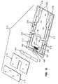
- FIG. 2is an exploded assembly view of the biosensor of FIG. 1 ;
- FIG. 3is an enlarged plan view of the biosensor of FIG. 1 showing a macroelectrode array and a microelectrode array;
- FIG. 4is a diagram of the deviation of an edge of an electrode element from a theoretical or ideal line representing the desired shape and placement of the edge;
- FIG. 5is a diagram of the deviation in gap width and placement resulting from the deviations in the two individual edges forming the gap
- FIG. 6is an enlarged section of the microelectrode array of FIG. 3 ;
- FIG. 7is a diagram of the deviation of an edge of an electrode element from a theoretical or ideal line representing the desired shape and placement of the edge;
- FIG. 8illustrates a cross-section taken along lines 8 - 8 of FIG. 1 ;
- FIG. 9illustrates a cross-section taken along lines 9 - 9 of FIG. 1 ;
- FIG. 10is a graph showing the deviation from mean or theoretical of an electrode edge of the microelectrode array of FIG. 3 ;
- FIG. 11is an exploded assembly view of a biosensor in accordance with another embodiment of the invention.
- FIG. 12is an exploded assembly view of a biosensor in accordance with another embodiment of the invention.
- FIG. 13is an exploded assembly view of a biosensor in accordance with another embodiment of the invention.
- FIG. 14is an exploded assembly view of a biosensor in accordance with another embodiment of the invention.
- FIG. 15is an exploded assembly view of a biosensor in accordance with another embodiment of the invention.
- FIG. 16is an enlarged perspective view of a biosensor in accordance with another embodiment of the invention.
- FIG. 17is a view of an ablation apparatus suitable for use with the present invention.
- FIG. 18is a view of the laser ablation apparatus of FIG. 17 showing a second mask
- FIG. 19is a view of an ablation apparatus suitable for use with the present invention.
- FIG. 20is a schematic of an electrode set ribbon of the present invention.
- FIG. 21is a photograph illustrating a biosensor substrate initially coated with a gold conductive layer from which approximately 10% of the conductive material has been removed;
- FIG. 22is a photograph illustrating a biosensor substrate having an electrical pattern with a gap width of approximately 20 ⁇ m and where approximately 20% of the conductive material initially covering the substrate has been removed to form the electrical pattern;
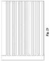
- FIG. 23is a photograph illustrating a biosensor substrate having an electrical pattern with a gap width of approximately 20 ⁇ m and where approximately 50% of the of a conductive material initially covering the substrate has been removed to form the electrical pattern;
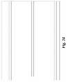
- FIG. 24is a photograph illustrating a biosensor substrate having an electrical pattern with a gap width of approximately 250 ⁇ m and where approximately 90% of the conductive material initially covering the substrate has been removed to form the electrical pattern.
- a biosensor in accordance with the present inventionprovides a surface with electrode patterns formed thereon, the electrode patterns preferably having a smooth edge quality. It is a particular aspect of the present invention that precise quality is obtained for the edges of the electrical components located on the biosensor. Having a smooth or high edge quality of the elements can contribute to greater precision, accuracy, and reproducibility of test results. Further, a smooth or high edge quality also allows for a great number of electrode arrays to be formed on a defined surface area of the biosensor. By increasing the edge quality of the elements, it is possible to increase the number of electrode elements and thus increase the achievable functionality in the defined surface area.
- These functionsmay include, for example: multiple measurement electrode pairs for simultaneous measurement of the same or different analytes, including by alternative means; electrodes used to provide correction factors for the basic measurement electrodes; electrodes for detecting dose application or sample sufficiency; multiple electrode traces to monitor electrode functioning or to provide detection or correction of defective traces; and multiple contact pads for coupling to the foregoing functionalities, or for providing additional features such as identification, calibration, or other information pertaining to the biosensor.
- the selected functionalities for a given biosensorcan be provided in a smaller space when the high edge quality allows closer placement of the electrical components. It is a feature of the present invention to enable all of this, and more, in a manner that is relatively fast, reliable and cost effective.
- a biosensor of the present inventionhas electrical components with edges that are smooth and are precisely located.
- the precise locating of the smooth edgeis important, particularly relative to a corresponding edge of another electrical component, and especially with respect to a paired element.
- the importance and the degree of quality of a component's edge quality and placementwill vary with the nature of the component.
- the edge smoothness and placementare important for the quality of the electrochemical results obtained by use of the macroelectrodes.
- One factor in the accuracy of such a testis the reproducibility of the area of each macroelectrode. Obtaining precise edge smoothness and placement will yield an area which is highly accurate.
- Another factor in the use of macroelectrodesis the placement of one of the electrodes relative to the other, e.g., the position of the counter element(s) in relationship to the position of the working element(s).
- biosensorsare generally operated based on calibration methods that rely on the reproducibility of the sizes and locations of the measuring electrodes, the ability to consistently produce lots of such tests trips can enhance the results achieved with the tests.
- the edge smoothness and placementcontribute to the results obtained from microelectrodes.
- the issuescan be magnified because of the number and relatively close placement of the numerous microelements. Poor edge quality can greatly affect the operating characteristics of microelectrodes, and the present invention helps to overcome this potential problem.
- an advantage of placing microelements in close proximityis the rapid establishment of steady-state operation. High edge quality and precise edge placement enables closer placement of the elements and in turn faster achievement of steady-state operation. In addition, such closer placement allows for a greater number of microelements to be placed in a given space.
- the present inventionprovides a high quality edge for the various electrical components on a biosensor.
- the quality of the edgerelates to the smoothness or uniformity of the edge relative to a theoretical profile of the edge.
- Non-limiting examples of such “smooth” edges formed in accordance with the present inventionare shown in FIGS. 21-24 .
- the smoothnessrelates simply to the deviation of the edge surface relative to the theoretical line defining the desired shape of the edge. It will be appreciated that any electrical component on a biosensor has an intended location and shape that will not be exactly duplicated by the physical embodiment.
- the extent to which the actual edge of the component varies from the theoretical oneis a measure of the smoothness of the edge. As discussed above, this smoothness or quality of the edge can be expressed in terms of the varying distance that the edge is spaced from a theoretical line over a specified length. This distance can be measured at closely spaced intervals, as discussed in detail below, and the standard deviation of the distance can be calculated. Further, the maximum value the distance achieves over a specified length is also a meaningful parameter.
- the manufacturing processmust be capable of producing edges that will vary by less (preferably much less) than 5 ⁇ m over the length of the gap. Otherwise, the electrodes may touch and thus short circuit.
- the extent to which a given portion of the component is “smooth”may vary.
- certain edges of the elementsare more critical than others.
- certain edges of the counter and working electrodesare adjacent one another and spaced closely together, while others are not.
- certain edgesare located within the sample-receiving chamber, and others are not.
- the present inventionrelates to providing smooth edges for all of the edges of the measuring electrodes.
- the inventionprovides smooth edges particularly for the edges of the measuring electrodes located within the sample-receiving chamber, and more particularly for the edges of the measuring elements that are adjacent to one another. “Adjacent edges” in this context refers to the fact that an edge of a counter element is closest to, i.e., adjacent to, an edge of an element of a working electrode with which the counter electrode is paired.
- the present inventionrelates in one aspect to providing macroelectrodes having a closely determined area.
- the desired accuracy of the provided areacan vary based on the absolute size of the macroelectrode, as determined by the quality of the edges defining the electrode.
- the smoothness of the edgesimproves, the difference between the area actually occupied by the electrode and the desired area decreases.
- the edges forming the gappreferably have a smoothness standard deviation of less than about 4 ⁇ m over the entire length of the edges; for elements spaced apart by 100 ⁇ m, the standard deviation is preferably less than about 2 ⁇ m.
- the desired smoothnesscan differ.
- the adjacent edgeshave a smoothness standard deviation of less than about 6 ⁇ m, preferably less than about 2 ⁇ m, and most preferably less than about 1 ⁇ m.
- the smoothness standard deviationis preferably less than about 1 ⁇ m, more preferably less than about 0.5 ⁇ m.
- the smoothness standard deviation for microelectrodesis preferably less than about 5% of the width of the gap between adjacent microelements (i.e., feature size), more preferably less than about 2% of the feature size.
- the other electrical componentscan be provided with smooth edges to facilitate close placement of such components.
- Such other componentspreferably have a smoothness standard deviation that is less than about 6 ⁇ m, and more preferably less than about 2 ⁇ m.
- the present inventionalso provides for the accurate placement of the electrical components relative to one another and to the overall biosensor.
- the relative placement of componentsis achieved, at least in part, by the use of broad field laser ablation that is performed through a mask or other device that has a precise pattern for the electrical components.
- the relative placement of the componentstherefore does not depend on the controlled movement of a rastering laser or of the substrate relative to the rastering laser.
- this accurate positioning of adjacent edgesis further enhanced by the close tolerances for the smoothness of the edges.
- the inventionprovides electrical components that have gaps or features that are precisely controlled. More specifically, the electrical components will have designed, theoretical configurations for the gaps between adjacent edges, whereas the physical embodiments will have variations and irregularities.
- the present inventionprovides gaps between adjacent edges that are highly uniform. Specifically, the present invention provides a “uniform gap,” which is defined as a gap for which the smoothness standard deviation for each edge defining the gap is less than about 6 ⁇ m. Preferably, the smoothness standard deviation of both edges defining the gap is less than about 2 ⁇ m, more preferably less than about 1 ⁇ m.
- the biosensor of the present inventionis suitable for use in a system for assessing an analyte in a sample fluid.
- the systemincludes a meter (not shown) and provides methods for evaluating the sample fluid for the target analyte. The evaluation may range from detecting the presence of the analyte to determining the concentration of the analyte.
- the analyte and the sample fluidmay be any for which the test system is appropriate.
- a preferred embodimentis described in which the analyte is glucose and the sample fluid is blood or interstitial fluid.
- the present inventionclearly is not so limited in scope.
- Non-limiting examples of meters suitable for use with the biosensor of the present invention for determination of the analyte in the sample fluidare disclosed in U.S. Pat. Nos. 4,963,814; 4,999,632; 4,999,582; 5,243,516; 5,352,351; 5,366,609; 5,405,511; and 5,438,271, the disclosures of each being incorporated herein by reference.
- the suitable meter(not shown) will include a connection with electrodes of the biosensor, and circuitry to evaluate an electrochemical signal corresponding to the concentration of the analyte.
- the metermay also include electrical components that determine whether the sample fluid has been received by the biosensor and whether the amount of sample fluid is sufficient for testing.
- the metertypically will store and display the results of the analysis, or may alternatively provide the data to a separate device.
- the biosensor of the present inventionforming part of the system can provide either a qualitative or quantitative indication for the analyte.
- the biosensorcooperates with the meter to indicate simply the presence of the analyte in the sample fluid.
- the biosensor and metermay also provide a reading of the quantity or concentration of the analyte in the sample fluid.
- the biosensoris useful for the determination of a wide variety of analytes.
- the biosensorfor example, is readily adapted for use with any suitable chemistry that can be used to assess the presence of the analyte.
- the biosensoris configured and used for the testing of an analyte in a biological fluid.
- the systemis described with respect to the detection of glucose in a biological fluid.
- the biosensoris also useful with a wide variety of sample fluids, and is preferably used for the detection of analytes in a biological fluid.
- the biosensoris useful in connection with reference fluids that are used in conventional fashion to verify the integrity of the system for testing.
- the biosensoris employed for the testing of glucose.
- the sample fluidin this instance may specifically include, for example, fresh capillary blood obtained from the finger tip or approved alternate sites (e.g., forearm, palm, upper arm, calf and thigh), fresh venous blood, and control solutions supplied with or for the system.
- the fluidmay be acquired and delivered to the biosensor in any fashion.
- a blood samplemay be obtained in conventional fashion by incising the skin, such as with a lancet, and then contacting the biosensor with fluid that appears at the skin surface. It is an aspect of the present invention that the biosensor is useful with very small fluid samples. It is therefore a desirable feature that only a slight incising of the skin is necessary to produce the volume of fluid required for the test, and the pain and other concerns with such method can be minimized or eliminated.
- Biosensor 210 in accordance with an embodiment of the present inventionhas two electrode patterns having different feature sizes on a common planar surface and thus permits the accurate measurement of an analyte in a fluid.
- biosensor 210comprises a base or base substrate 212 , conductive material 216 positioned on the base 212 , a spacer 214 , and a cover 218 .
- the cover 218 and spacer 214cooperate with the base 212 to define a sample-receiving chamber 220 ( FIG. 9 ) having a sample inlet opening 221 for the sample fluid, and a reagent 264 for producing an electrochemical signal in the presence of a test analyte.
- the biosensor 210is formed as a test strip, particularly one having a laminar construction providing an edge or surface opening to the sample-receiving chamber 220 .
- the reagent 264as shown in FIGS. 2 and 9 , is exposed by the sample-receiving chamber 220 to provide the electrochemical signal to a working electrode also positioned within the chamber 220 .
- the reagentmay contain an enzyme and optionally a mediator.
- the base 212 of biosensor 210includes edges 222 that define opposite ends 224 , 226 and sides 228 , 230 extending between the ends 224 , 226 .
- Base 212also has a top surface 232 supporting the conductive material 216 and an opposite bottom surface 234 ( FIGS. 8 and 9 ).
- base 212has a length of 40 mm and a width of 10 mm. It is appreciated, however that these values are merely illustrative and that the dimensions of the base 212 may vary in accordance with the present disclosure.
- the base 212is a substrate that is formed from an insulating material, so that it will not provide an electrical connection between electrodes formed from the conductive material 216 .
- suitable insulating materialsinclude glass, ceramics and polymers.
- the baseis a flexible polymer and has a strong absorbance in the UV.
- suitable materialsinclude polyethylene terephthalate (PET), polyethylene naphthalate (PEN), and polyimide films.
- PETpolyethylene terephthalate
- PENpolyethylene naphthalate
- the suitable filmsare commercially available as MELINEX®, KALADEX® and KAPTON®, respectively from E.I. duPont de Nemours, Wilmington, Del., USA (“duPont”) and UPILEX®, a polyimide film from UBE Industries Ltd, Japan.
- Preferred materialsare selected from 10 mil thick MELINEX® 329 or KAPTON®, which are coated with 50 ⁇ 4 nm gold within-lot C.V. of ⁇ 5% by: Techni-Met Advanced Depositions, Inc., Windsor, Conn., USA. It is appreciated that the base 212 may be either purchased pre-coated with conductive material 216 or may be coated by sputtering or vapor deposition, in accordance with this disclosure. It is further appreciated that the thickness of the conductive material can vary in accordance with this disclosure.
- Spacer 214is illustratively positioned on the top surface 232 of the base 212 adjacent to end 224 .
- Spacer 214has an upper surface 236 and a lower surface 238 ( FIG. 9 ) facing the base 212 .
- the spacer 214has edges 240 , 242 , 244 , 246 .
- spacer 214has a length of about 6 mm, a width of about 10 mm and a height of about 4 mil. It is appreciated, however that these values are merely illustrative and that the biosensor may be formed without a spacer and that the dimensions of the spacer 214 may vary in accordance with the present disclosure.
- Spacer 214is formed from an insulating material, so that it will not provide an electrical connection between electrodes formed from the conductive material 216 .
- suitable insulating materialsinclude glass, ceramics, polymers, photoimageable coverlay materials, and photoresists—non-limiting examples of which are disclosed in U.S. patent application Serial No. Ser. No. 10/264,891, filed Oct. 4, 2002, the disclosure of which is incorporated herein by reference.
- spacer 214is formed of 4 mil MELINEX® polyester film, which is preferred for use with whole blood samples. It is appreciated, however, that when the sample is plasma or serum, 1-2 mil film may be preferred for use in accordance with this disclosure. It is appreciated, however that these values are merely illustrative and that the composition and dimension of the spacer 214 may vary in accordance with the desired height of the sample-receiving chamber.
- a slit or void 248is formed in the spacer 214 and extends from the edge 240 toward the edge 242 .
- the slit 248defines at least the length and width of the sample-receiving chamber 220 and is defined by edges 249 .
- the slit 248has a length of 5 mm, a width of 1 mm, and a height of 0.1 mm, but may have a variety of lengths and widths in accordance with the present disclosure. It is further appreciated that the edges 249 of the slit may also be curved or angular in accordance with this disclosure.
- the cover 218is positioned on the upper surface 236 of spacer 214 .
- Cover 218has a first surface 250 and a second surface 252 ( FIG. 9 ) facing the base 212 . Further, the cover 218 has edges 254 , 256 , 258 , 260 .
- the cover 218has a length that is less than the length of the slit 248 .
- cover 218has a length of about 4 mm, a width of about 10 mm and a height of about 0.1 mm. It is appreciated, however that these values are merely illustrative and that the biosensor may be formed without a cover and that the dimensions of the cover 218 may vary in accordance with the present disclosure.
- the cover 218is illustratively formed of a clear material having a hydrophilic adhesive layer in proximity to the spacer.
- materials suitable for cover 218include polyethylene, polypropylene, polyvinylchloride, polyimide, glass, or polyester.
- a preferred material for cover 218is 100 ⁇ m polyester.
- a preferred adhesiveis ARCare 8586 having a MA-55 hydrophilic coating, commercially available from Adhesives Research Inc., Glen Rock, Pa. Further, it is appreciated that the cover may have markings in accordance with this disclosure.
- This sample-receiving chamber 220can act as a capillary channel, drawing the fluid to be tested from the opening 221 onto a sensing region of the conductive material 216 and toward a vent 262 .
- the biosensormay be formed without a spacer in accordance with this disclosure and that in addition to or instead of the spacer and the cover, a variety of dielectric materials may cover the base 212 exposing only selected portions of the conductive material in accordance with this disclosure.
- the dimensions of the channel 220may vary in accordance with this disclosure.
- FIG. 2illustrates the conductive material 216 defining electrode systems comprising a first electrode set 266 and a second electrode set 268 , and corresponding traces 279 , 277 and contact pads 278 , 282 , respectively.
- the conductive material 216may contain pure metals or alloys, or other materials, which are metallic conductors.
- the conductive materialis transparent at the wavelength of the laser used to form the electrodes and of a thickness amenable to rapid and precise processing.
- Non-limiting examplesinclude aluminum, carbon, copper, chromium, gold, indium tin oxide (ITO), palladium, platinum, silver, tin oxide/gold, titanium, mixtures thereof, and alloys or metallic compounds of these elements.
- the conductive materialincludes noble metals or alloys or their oxides. Most preferably, the conductive material includes gold, palladium, aluminum, titanium, platinum, ITO and chromium.
- the conductive materialranges in thickness from about 10 nm to 80 nm, more preferably, 30 nm to 70 nm.
- FIGS. 1-3 , 6 , and 8 - 9illustrate the biosensor 210 with a 50 nm gold film. It is appreciated that the thickness of the conductive material depends upon the transmissive property of the material and other factors relating to use of the biosensor.
- the conductive material 216is ablated into two electrode systems that comprise sets 266 , 268 .
- the conductive material 216is removed from at least about 5% of the surface area of the base 212 , more preferably at least about 50% of the surface area of the base 212 , and most preferably at least about 90% of the surface area of the base 212 .
- the only conductive material 216 remaining on the base 212forms at least a portion of an electrode system.
- the resulting patterned conductive materialcan be coated or plated with additional metal layers.
- the conductive materialmay be copper, which is then ablated with a laser, into an electrode pattern; subsequently, the copper may be plated with a titanium/tungsten layer, and then a gold layer, to form the desired electrodes.
- a single layer of conductive materialis used, which lies on the base 212 .
- seed or ancillary layerssuch as chromium nickel or titanium.
- biosensor 210has a single layer of gold, palladium, platinum or ITO.
- the biosensor 210includes an electrode system comprising at least a working electrode and a counter electrode within the sample-receiving chamber 220 .
- the sample-receiving chamber 220is configured such that sample fluid entering the chamber is placed in electrolytic contact with both the working electrode and the counter electrode. This allows electrical current to flow between the electrodes to effect the electrooxidation or electroreduction of the analyte or its products.
- the first electrode set 266 of the electrode systemincludes two electrodes 270 , 272 .
- electrode 270is a working electrode and electrode 272 is a counter electrode.
- the electrodes 270 , 272each have a single element or finger 280 that is in communication with a contact pad 278 via a connecting trace 279 (shown in FIG. 2 ).
- the electrode fingers 280 of the electrodes 270 , 272cooperate to define an electrode pattern formed as a macroelectrode array. It is appreciated, as will be discussed hereafter, that the electrodes 270 , 272 can include more than one finger each in accordance with this disclosure. It is further appreciated that the shape, size and relative configuration of the electrodes or electrode fingers may vary in accordance with the present disclosure.
- the second electrode set 268includes two electrodes 274 , 276 .
- electrode 274is a working electrode and electrode 276 is a counter electrode.
- the electrodes 274 , 276each have five electrode elements or fingers 284 that are in communication with a contact pad 282 via a connecting trace 277 .
- the electrode fingers 284cooperate to define an electrode pattern formed as an interlaced microelectrode array. While five electrode fingers 284 are illustrated, it is appreciated that the elements of electrodes 274 , 276 can each be formed with greater or fewer than five electrode fingers in accordance with this disclosure. It is further appreciated that the shape, size and relative configuration of the electrodes may vary in accordance with the present disclosure.
- the values for the dimensions of the electrode sets 266 , 268 as illustrated in FIG. 2are for a single specific embodiment, and these values may be selected as needed for the specific use.
- the length of the electrode setsmay be any length up to the length of the base, depending upon the orientation of the electrode sets on the base.
- the width of the conducting traces in communication with the electrode setsmay vary, a non-limiting example of which is from about 0.4 mm to about 5 mm.
- the width of each contact padmay vary, a non-limiting example of which is from about 1 mm to about 5 mm.
- each base 212can contain, for example 1 to 1000 electrode sets, preferably 2 to 20 electrode sets, more preferably 2 to 3 electrode sets.
- each electrode finger 280is defined by an inner edge 281 , an outer edge 283 , and opposite third and fourth edges 285 , 287 .
- Each edge 218 , 283 , 285 , 287has a smooth edge quality.
- the edge quality of the electrodes 270 , 272is defined by the edge's deviation from a theoretical line extending between first and second points. The following description of deviations can apply to each edge of electrodes 270 , 272 of biosensor 210 . For clarity purposes, however, only the edge 281 of electrode 270 will be discussed hereafter.
- the edge 281 of electrode 270extends between points 289 , 291 located on the base 212 .
- Points 289 , 291are located at opposite ends of the inner edge 281 , which represents the entire length of the gap 286 between electrodes 280 . It is appreciated that the points 289 , 291 may be positioned at a variety of locations and at a variety of distances relative to one another depending upon the length of the desired edge in accordance with this disclosure. However, the length of interest will typically be the entire length over which a gap extends, since the smoothness of the adjacent edges is normally most important over this entire length.
- FIG. 4illustrates the theoretical line 293 that extends exactly between points 289 , 291 . That is, line 293 represents the ideal or desired edge that would be obtained if the process of forming the electrodes were perfect. However, at any given point along the length of line 293 , the edge 281 will be spaced in either direction from theoretical line 293 by a distance “d i .” The distance d i varies from zero to a maximum value depending upon where it happens to be measured, as shown, e.g., with reference to distances d 1 , d 2 , d 3 and d 4 in FIG. 4 .
- a standard deviation of this distance over the length of line 293is less than about 6 ⁇ m in accordance with this disclosure, creating an edge with a smooth edge quality.
- the standard deviation of the edge 281 from theoretical line 293is less than 2 ⁇ m, and most preferably less than 1.0 ⁇ m.
- An example of this deviation from mean or theoreticalis illustrated in FIG. 10 .
- the edge quality illustrated in FIG. 10was measured using Micro-Measure system commercially available from LPKF Laser Electronic GmbH, of Garbsen, Germany with Metric 6.21 software.
- the Metric softwareallows the display and measuring of video images on a PC. Measurements were made by capturing the image and then allowing the software to place a 10 ⁇ m grid over the image. The grid was aligned with the edge by moving the electrode structure under the measurement objective. (By physically manipulating the image, the edge can be vertically aligned to be parallel with the grid.) Using the software, measurements from the grid line to the electrode edge were then made at 10 ⁇ m intervals along the length of a line 250 ⁇ m long using a point-to-point process.
- Standard deviationswere calculated from measurements made at an average interval of 0.69 ⁇ m for a length of at least 250 ⁇ m.
- Ring lightingIntensity 89, Position 60
- the standard deviation from the mean valuewas less than about 2 ⁇ m.
- the line 293is illustratively a straight line. It is appreciated, however, that the shape of the line 293 may be curved or angular, so long as the standard deviation of the distance of edge 281 from that line 293 over the length of the edge is less than about 6 ⁇ m.
- the electrode fingers 280are separated from one another by an electrode gap 286 , which corresponds to the feature size of the electrode pattern of the electrode set 266 .
- the electrode gap 286 shown in FIG. 3is shown as formed by two straight edges 281 .
- the placement of edges 281varies from theoretical value 293 ( FIG. 4 ) by a distance that varies along the length of the edge.
- the electrically insulative material of the top surface 232is exposed between the electrode fingers 280 along a length 290 . It is appreciated, however, that rather than top surface 232 being exposed, the base can be coated with materials, or recesses can be formed between the electrodes as disclosed in U.S. patent application Ser. No. 09/704,145, filed on Nov. 1, 2000, now U.S. Pat. No. 6,540,890, the disclosure of which is incorporated herein by reference.
- the inner edges 281 of electrode fingers 280have an equal length, illustrated by the numeral 290 and are separated from one another by the electrode gap 286 , whose length is also represented by length 290 . Because the two edges 281 defining gap 286 are not perfect, gap 286 will in fact vary in width and placement over its length, as shown with reference to gaps 292 a - 292 d in FIG. 5 . When the deviations of the two edges defining gap 286 are in the same direction, they tend to cancel each other as to width deviation, at least in part, and cause a net shift in placement of the gap, as illustrated with respect to reference numerals 292 c and 292 d of FIG. 5 .
- a theoretical gapcan be defined by two theoretical lines 293 associated with edges 281 .
- the quality of the gap or its deviation from the theoretical gapcan be specified in terms of the quality of the two individual edges defining it.
- the smoothness standard deviation of both edges defining gap 286is less 6 ⁇ m, preferably less than 2.0 ⁇ m, and most preferably less than 1 ⁇ m.
- the electrode fingers 284which define the elements of electrodes 274 , 276 are illustrated in FIGS. 3 and 6 . For clarity purposes, however, only three of these electrode fingers 284 will be discussed hereafter as they are illustrated in FIG. 6 .
- Each electrode finger 284is defined by a first edge 296 and a second edge 297 . Further, adjacent fingers 284 have spaced-apart third and fourth edges 298 , 299 respectively. These edges 296 , 297 , 298 , 299 of fingers 284 can also have a smooth edge quality. As previously described with reference to electrodes 270 , 272 , the edge quality of the electrodes 274 , 276 is defined by the respective edge's deviation from a line extending between first and second points. The following description of deviations will apply to each edge of electrode fingers 284 of biosensor 210 . For clarity purposes, however, only one edge 296 of electrode finger 284 will be discussed hereafter.
- the edge 296 of electrode finger 284extends between first and second points 301 , 302 located on the base 212 .
- a theoretical line 300extends exactly between points 301 , 302 , which is typically the length of the gap formed by edge 296 and 297 .
- a standard deviation of the varying distance of edge 296 from line 300is less than about 6 ⁇ m, in accordance with this disclosure, creating an edge with a smooth edge quality.
- the standard deviation of the edge 296 from theoretical line 300is less than 2 ⁇ m, and most preferably less than 1.0 ⁇ m.
- the line 300is a straight line. It is appreciated, however, that the shape of the line 300 may be curved or angular. It is also appreciated that the specific positions of first and second locations 300 , 301 on the surface 232 may vary in accordance with the disclosure, although the lengths of most importance are typically the entire length of the gaps between these closely spaced electrode fingers.
- the electrode fingers 284are separated from one another by an electrode gap 288 , which corresponds to the feature size of the electrode pattern of the electrode set 268 .
- the electrode gap 288relates to the width between adjacent edges 296 , 297 of fingers 284 . Because the two edges defining gap 288 are not perfect, gap 288 will in fact vary in position and placement over its length.
- the electrically insulative material of the base 212is exposed between the electrode fingers 284 along a length 303 . It is appreciated, however, that rather than top surface 232 being exposed, the base can be coated with materials, or recesses can be formed between the electrodes as disclosed in U.S. patent application Ser. No. 09/704,145, filed on Nov. 1, 2000, now U.S. Pat. No. 6,540,890, entitled “Biosensor”, the disclosure of which is incorporated herein by reference.
- the electrode gap 288which corresponds to the feature size of the electrode pattern of the electrode set 268 is different than the feature size of the electrode pattern of the electrode set 266 .
- the feature size, or gap 288 between the electrode fingers 284has a width of about 100 ⁇ m or less, including about 1 ⁇ m to about 100 ⁇ m, even more preferably 75 ⁇ m or less, including about 17 ⁇ m to about 50 ⁇ m.
- the electrode gap for a microelectrode arraycan vary.
- the electrode gapcan be less than 1 ⁇ m in accordance with the present disclosure.
- the size of the achievable gapis dependent upon the quality of the optics, the wavelength of the laser, and the window size of a mask field.
- the gap 288has a width along a length 303 of the opposing edges 296 , 297 of the electrode fingers 284 .
- the quality of gap 286 or its deviation from a theoretical gapcan be specified in terms of the quality of the two individual edges defining it.
- the smoothness standard deviation of both edges defining gap 286is less 6 ⁇ m, preferably less than 2.0 ⁇ m, and most preferably less than 1 ⁇ m.
- the electrode fingers 284are covered with the reagent 264 and may be used to provide electrochemical probes for specific analytes.
- the starting reagentsare the reactants or components of the reagent, and are often compounded together in liquid form before application to the ribbons or reels, or in capillary channels on sheets of electrodes. The liquid may then evaporate, leaving the reagent in solid form.
- the choice of a specific reagentdepends on the specific analyte or analytes to be measured, and is not critical to the present invention.
- Various reagent compositionsare well known to those of ordinary skill in the art. It is also appreciated that the placement choice for the reagent on the base may vary and depends on the intended use of the biosensor. Further, it is appreciated that the techniques for applying the reagent onto the base may vary. For example, it is within the scope of the present disclosure to have the reagent screen-printed onto the fingers.
- a non-limiting example of a dispensable reagent for measurement of glucose in a human blood samplecontains 62.2 mg polyethylene oxide (mean molecular weight of 100-900 kilodaltons), 3.3 mg NATROSOL 250 M, 41.5 mg AVICEL RC-591 F, 89.4 mg monobasic potassium phosphate, 157.9 mg dibasic potassium phosphate, 437.3 mg potassium ferricyanide, 46.0 mg sodium succinate, 148.0 mg trehalose, 2.6 mg TRITON X-100 surfactant, and 2,000 to 9,000 units of enzyme activity per gram of reagent.
- the enzymeis prepared as an enzyme solution from 12.5 mg coenzyme PQQ and 1.21 million units of the apoenzyme of quinoprotein glucose dehydrogenase, forming a solution of quinoprotein glucose dehydrogenase.
- This reagentis further described in U.S. Pat. No. 5,997,817, the disclosure of which is expressly incorporated herein by reference.
- a non-limiting example of a dispensable reagent for measurement of hematocrit in a samplecontains oxidized and reduced forms of a reversible electroactive compound (potassium hexacyanoferrate (III) (“ferricyanide”) and potassium hexacyanoferrate (II) (“ferrocyanide”), respectively), an electrolyte (potassium phosphate buffer), and a microcrystalline material (Avicel RC-591F—a blend of 88% microcrystalline cellulose and 12% sodium carboxymethyl—cellulose, available from FMC Corp.).
- Concentrations of the components within the reagent before dryingare as follows: 400 millimolar (mM) ferricyanide, 55 mM ferrocyanide, 400 mM potassium phosphate, and 2.0% (weight: volume) Avicel.
- mMmillimolar
- ferrocyanidea further description of the reagent for a hematocrit assay is found in U.S. Pat. No. 5,385,846, the disclosure of which is expressly incorporated herein by reference.
- Non-limiting examples of enzymes and mediators that may be used in measuring particular analytes in biosensors of the present inventionare listed below in Table 1.
- At least one additional enzymeis used as a reaction catalyst.
- some of the examples shown in Table 1may utilize an additional mediator, which facilitates electron transfer to the oxidized form of the mediator.
- the additional mediatormay be provided to the reagent in lesser amount than the oxidized form of the mediator.
- nitrosoanaline reagentwhich includes a PQQ-GDH and para-Nitroso-Aniline mediator.
- a protocol for the preparation of the nitrosoanaline reagentis the same in all respects as disclosed in U.S. patent application Ser. No. 10/688,312, entitled “System And Method For Analyte Measurement Using AC Phase Angle Measurement”, filed Oct. 17, 2003, the disclosure of which is incorporated herein by reference.
- the reagent mass composition—prior to dispensing and dryingis as set forth in Table 2.
- a coatable reagent suitable for use with the present disclosureis as follows in Table 3.
- Biosensor 210is illustratively manufactured using two apparatuses 10 , 10 ′, shown in FIGS. 17-18 and 19 , respectively. It is appreciated that unless otherwise described, the apparatuses 10 , 10 ′ operate in a similar manner. Referring first to FIG. 17 , biosensor 210 is manufactured by feeding a roll of ribbon or web 20 having an 80 nm gold laminate, which is about 40 mm in width, into a custom fit broad field laser ablation apparatus 10 .
- the apparatus 10comprises a laser source 11 producing a beam of laser light 12 , a chromium-plated quartz mask 14 , and optics 16 . It is appreciated that while the illustrated optics 16 is a single lens, optics 16 is preferably a variety of lenses that cooperate to make the light 12 in a pre-determined shape or image that is then projected onto the web of base substrate 20 .
- a non-limiting example of a suitable ablation apparatus 10is a customized MicrolineLaser 200-4 laser system commercially available from LPKF Laser Electronic GmbH, of Garbsen, Germany, which incorporates an LPX-400, LPX-300 or LPX-200 laser system commercially available from Lambda Physik AG, Gottingen, Germany and a chromium-plated quartz mask commercially available from International Phototool Company, Colorado Springs, Co.
- the laser source 11is a LPX-200 KrF-UV-laser. It is appreciated, however, that higher wavelength UV lasers can be used in accordance with this disclosure.
- the laser source 11works at 248 nm, with a pulse energy of 600 mJ, and a pulse repeat frequency of 50 Hz.
- the intensity of the laser beam 12can be infinitely adjusted between 3% and 92% by a dielectric beam attenuator (not shown).
- the beam profileis 27 ⁇ 15 mm 2 (0.62 sq. inch) and the pulse duration 25 ns.
- the layout on the mask 14is homogeneously projected by an optical elements beam expander, homogenizer, and field lens (not shown).
- the performance of the homogenizerhas been determined by measuring the energy profile.
- the imaging optics 16transfer the structures of the mask 14 onto the ribbon 20 .
- the imaging ratiois 2:1 to allow a large area to be removed on the one hand, but to keep the energy density below the ablation point of the applied chromium mask on the other hand. While an imaging of 2:1 is illustrated, it is appreciated that the any number of alternative ratios are possible in accordance with this disclosure depending upon the desired design requirements.
- the ribbon 20moves as shown by arrow 25 to allow a number of layout segments to be ablated in succession.
- the positioning of the mask 14 , movement of the ribbon 20 , and laser energyare computer controlled. As shown in FIG. 17 , the laser beam 12 is projected onto the ribbon 20 to be ablated. Light 12 passing through the clear areas or windows 18 of the mask 14 ablates the metal from the ribbon 20 . Chromium coated areas 24 of the mask 14 blocks the laser light 12 and prevent ablation in those areas, resulting in a metallized structure on the ribbon 20 surface. Referring now to FIG. 18 , a complete structure of electrical components may require additional ablation steps through a second mask 14 ′. It is appreciated that depending upon the optics and the size of the electrical component to be ablated, that only a single ablation step or greater than two ablation steps may be necessary in accordance with this disclosure. Further, it is appreciated that instead of multiple masks, that multiple fields may be formed on the same mask in accordance with this disclosure.
- a second non-limiting example of a suitable ablation apparatus 10 ′is a customized laser system commercially available from LPKF Laser Electronic GmbH, of Garbsen, Germany, which incorporates a Lambda STEEL (Stable Energy Excimer Laser) laser system commercially available from Lambda Physik AG, Göttingen, Germany and a chromium-plated quartz mask commercially available from International Phototool Company, Colorado Springs, Co.
- the laser systemfeatures up to 1000 mJ pulse energy at a wavelength of 308 nm. Further, the laser system has a frequency of 100 Hz.
- the apparatus 10 ′may be formed to produce biosensors with two passes as shown in FIGS. 17 and 18 , but preferably its optics permit the formation of a 10 ⁇ 40 mm pattern in a 25 ns single pass.
- the laser pulse or beam 12 that passes through the mask 14 , 14 ′, 14 ′′is absorbed within less than 1 ⁇ m of the surface 232 on the ribbon 20 .
- the photons of the beam 12have an energy sufficient to cause photo-dissociation and the rapid breaking of chemical bonds at the metal/polymer interface. It is believed that this rapid chemical bond breaking causes a sudden pressure increase within the absorption region and forces material (metal film 216 ) to be ejected from the polymer base surface. Since typical pulse durations are around 20-25 nanoseconds, the interaction with the material occurs very rapidly and thermal damage to edges of the conductive material 216 and surrounding structures is minimized. The resulting edges of the electrical components have high edge quality and accurate placement as contemplated by the present invention.
- Fluence energies used to remove or ablate metals from the ribbon 20are dependent upon the material from which the ribbon 20 is formed, adhesion of the metal film to the base material, the thickness of the metal film, and possibly the process used to place the film on the base material, i.e. supporting and vapor deposition.
- Fluence levels for gold on KALADEX®range from about 50 to about 90 mJ/cm 2 , on polyimide about 100 to about 120 mJ/cm 2 , and on MELINEX® about 60 to about 120 mJ/cm 2 . It is understood that fluence levels less than or greater than the above mentioned can be appropriate for other base materials in accordance with the disclosure.
- Patterning of areas of the ribbon 20is achieved by using the masks 14 , 14 ′.
- Each mask 14 , 14 ′illustratively includes a mask field 22 containing a precise two-dimensional illustration of a pre-determined portion of the electrode component patterns to be formed.
- FIG. 17illustrates the mask field 22 including contact pads and a portion of traces.
- the second mask 14 ′contains a second corresponding portion of the traces and the electrode patterns containing fingers.
- the mask 14can contain a complete illustration of the entire electrode pattern for each biosensor ( FIG. 19 ), or partial patterns different from those illustrated in FIGS. 17 and 18 in accordance with this disclosure.
- the entire pattern of the electrical components on the test stripare laser ablated at one time, i.e., the broad field encompasses the entire size of the test strip ( FIG. 19 ), or even encompasses the entire size of two or more test strips (not shown).
- the entire pattern of the electrical components on the test stripare laser ablated at one time, i.e., the broad field encompasses the entire size of the test strip ( FIG. 19 ), or even encompasses the entire size of two or more test strips (not shown).
- portions of the entire biosensorare done successively.
- mask 14will be discussed hereafter, it is appreciated that unless indicated otherwise, the discussion will apply to masks 14 ′, 14 ′′ as well.
- areas 24 of the mask field 22 protected by the chromewill block the projection of the laser beam 12 to the ribbon 20 .
- Clear areas or windows 18 in the mask field 22allow the laser beam 12 to pass through the mask 14 and to impact predetermined areas of the ribbon 20 .
- the clear area 18 of the mask field 22corresponds to the areas of the ribbon 20 from which the conductive material 216 is to be removed.
- the mask field 22has a length shown by line 30 and a width as shown by line 32 .
- the length 30 of the maskis two times the length of a length 34 of the resulting pattern and the width 32 of the mask is two times the width of a width 36 of the resulting pattern on ribbon 20 .
- the optics 16reduces the size of laser beam 12 that strikes the ribbon 20 . It is appreciated that the relative dimensions of the mask field 22 and the resulting pattern can vary in accordance with this disclosure.
- Mask 14 ′( FIG. 18 ) is used to complete the two-dimensional illustration of the electrical components.
- the excimer laser source 11emits beam 12 , which passes through the chrome-on-quartz mask 14 .
- the mask field 22causes parts of the laser beam 12 to be reflected while allowing other parts of the beam to pass through in the form of an image of part or all of an electrode pattern.
- the image or part of laser beam 12 that passes through mask 14in turn creates a pattern on the gold film where impacted by the laser beam 12 .
- ribbon or web 20can be stationary relative to apparatus 10 or move continuously on a roll through apparatus 10 .
- non-limiting rates of movement of the ribbon 20can be from about 0 m/min to about 100 m/min, more preferably about 30 m/min to about 60 m/min. It is appreciated that the rate of movement of the ribbon 20 is limited only by the apparatus 10 selected and may well exceed 100 m/min depending upon the pulse duration of the laser source 11 in accordance with the present disclosure.
- masks 14 , 14 ′large areas of the web or ribbon 20 can be patterned using step-and-repeat processes involving multiple mask fields 22 in the same mask area to enable the economical creation of intricate electrode patterns and other electrical components on a substrate of the base, the precise edges of the electrode components, and the removal of greater amounts of the metallic film from the base material.
- FIG. 20is a non-limiting schematic of an electrode set ribbon 124 formed in accordance with the present disclosure, although having an electrode pattern different from that illustrated in FIGS. 17 and 18 .
- the ribbon 124includes a plurality of panels 120 , each of which includes a plurality of electrode systems 116 . Each system includes two electrodes, both labeled 104 and having a sensing region 110 . Also shown is the original metallic laminate ribbon 122 that is subject to laser ablation to form the electrode set ribbon 124 .
- the width of the ribbon 122is selected to accommodate the laser ablation system 10 , 10 ′, and may be, for example, 40 to 0.4 inches (1.2 m to 10.25 mm).
- the ribbonmay be any length, and is selected based on the desired number of electrode sets, and/or the ease of handling and transport of the ribbons.
- the size of each individual panelis selected to fit conveniently on the ribbon, and therefore each panel may contain 1 to 1000 electrode sets, preferably 2 to 20 electrode sets.
- the ribbon 20may be coupled to a spacer and a cover using any number of well-known commercially available methods.
- a non-limiting example of a suitable method of manufactureis described in detail in U.S. Application Ser. No. 60/480,397, filed Jun. 20, 2003, entitled “Devices And Methods Relating To Analyte Sensors”, the disclosure of which is incorporated herein by reference.
- a reagent filmis placed upon the ribbon and dried conventionally with an in-line drying system. The rate of processing is nominally 30-38 meters per minute and depends upon the rheology of the reagent.
- Reagents suitable for the biosensor 210are given above, but a preferable reagent is set out in Table 2.
- the materialsare processed in continuous reels such that the electrode pattern is orthogonal to the length of the reel, in the case of the base.
- the spacer materialis laminated onto the coated ribbon 20 .
- a portion of the spacer materialPrior to laminating the spacer material, however, a portion of the spacer material is removed, thereby forming a slit.
- a punching processis used to remove the unneeded portion of the spacer.
- the die setgoverns the shape of the slit.
- the resulting slit-spaceris placed in a reel-to-reel process onto the base.
- a coveris then laminated onto the spacer using a reel-to reel process.
- the biosensorscan then be produced from the resulting reels of material by means of slitting and cutting.
- the slit in the spacerpreferably forms a capillary fill space between the base and the cover.
- a hydrophobic adhesive on the spacerprevents the test sample from flowing into the reagent under the spacer and therefore the fill space defines the test chamber volume. It is appreciated that the chamber volume can vary in accordance with this disclosure depending upon the application of the biosensor. A non-limiting detailed description of suitable fill volumes is found in U.S. Application Ser. No. 60/480,397, noted above.
- biosensor 210has two electrode patterns having different feature sizes on a common planar surface and thus achieves multiple functionalities on that surface.
- electrode set 266has an electrode pattern formed as a macro electrode array with a first pre-defined feature size.
- a non-limiting example of a suitable functionality of the macroelectrode arrayis hematocrit level correction, which is described in U.S. patent application Ser. No. 10/688,312, entitled “System And Method For Analyte Measurement Using AC Phase Angle Measurement”, filed Oct. 17, 2003, the disclosure of which is incorporated herein by reference.
- Electrode set 268has an electrode pattern formed as an interlaced microelectrode array with a second pre-defined feature size.
- a non-limiting example of a suitable functionality of the microelectrode arrayis glucose estimation, which is also described in U.S. patent application Ser. No. 10/688,312.
- a test meter(not shown) applies a voltage to one electrode and measures the current response at the other electrode to obtain a signal as described in U.S. patent application Ser. No. 10/688,312.
- a userplaces his or her lanced finger at opening 221 of biosensor 210 .
- a liquid sample(whole blood) flows from the finger into the opening 221 .
- the liquid sampleis transported via capillary action through the sample-receiving chamber 220 and across the fingers 280 of the element of the electrode set 266 .
- the liquid sampleflows through the sample-receiving chamber 220 toward vent 262 and into engagement with the reagent 264 situated upon the fingers 284 of the element of the electrode set 268 .
- hematocrit correction valuesare determined from the interaction of the liquid sample with the fingers 280 and a glucose determination from the interaction of the liquid sample/reagent mixture with the fingers 284 . While hematocrit and glucose determination functionalities are described with reference to biosensor 210 , it is appreciated that the electrode patterns, may be used for a variety of functionalities in accordance with the present disclosure.
- biosensorsespecially for use in diagnostic devices.
- electrochemical biosensorsfor non-diagnostic uses, such as measuring an analyte in any biological, environmental, or other, sample.
- biosensorsmay stand alone or be combined with one another in accordance with this disclosure.
- each of the disclosed biosensorsoperates from the standpoint of a user in a manner similar to that described above with reference from 210 .
- like components of the biosensorsare numbered alike.
- a biosensor 310is formed and manufactured in a manner similar to biosensor 210 except for the pattern of the conductive material 216 positioned on the base 212 .
- the conductive material 216 of biosensor 310defines a first electrode system 366 and a second electrode system 368 .
- the electrode systems 366 , 368are similar to the systems of biosensor 210 except for the resulting pattern of the connecting traces 377 , 379 and contact pads 378 , 383 on the base 212 . It is submitted that the traces 377 , 379 and pads 378 , 383 may take on a variety of shapes and sizes in accordance with this disclosure.
- a biosensor 510is formed in a manner similar to biosensor 210 except for the pattern of the conductive material 216 positioned on the base 212 .
- the conductive material 216 of biosensor 510defines a first electrode set 566 .
- the electrode set 566is similar to set 366 except for the configuration of the interlacing electrode pattern formed by the elements of the electrodes.
- the first electrode set 566includes a working electrode having an element with one electrode finger 581 and a counter electrode having an element with two electrode fingers 580 .
- the fingers 580 , 581cooperate with one another to create an interlaced electrode pattern configured as a macroelectrode array having a feature size or gap width of about 250 ⁇ m.
- the electrodes 580 , 581each have an electrode width of about 250 ⁇ m. As discussed above with set 266 , the electrode and gap widths may vary in accordance with this disclosure.
- the first and second electrode sets 566 , 268have different feature sizes and are used to create different functionalities on biosensor 510 .
- a non-limiting example of a suitable functionality of the first electrode set 566is for determining correction factors for hematocrit levels. The measurement methods are as discussed above with reference to biosensor 210 .
- a biosensor 610is formed in a manner similar to biosensor 210 except for the pattern of the conductive material 216 positioned on the base 212 .
- the conductive material 216 of biosensor 610defines a second electrode set 668 spaced-apart from set 566 .
- the electrode set 668is similar to set 268 except for the pattern of interlacing electrode pattern in the element of the electrodes.
- the second electrode set 668includes a working electrode and a counter electrode, each having an element with three electrode fingers 661 .
- the fingers 661cooperate with one another to define an interlaced electrode pattern configured as a microelectrode array having a feature size or gap width of about 50 ⁇ m, which is less than the feature size of the electrode pattern of the set 566 .
- the electrodes 661each have an electrode width of about 50 ⁇ m. As discussed above with set 268 , the electrode and gap widths may vary in accordance with this disclosure.
- biosensor 610includes a reagent 664 .
- Reagent 664is similar to reagent 264 , and only differs in its width as it is applied onto the base 212 . Specifically, the reagent 664 extends across electrode fingers 661 .
- a non-limiting example of a suitable functionality of the second electrode set 668is a glucose determination functionality. The measurement methods are as discussed above with reference to biosensor 210 .
- a biosensor 710is formed in a manner similar to biosensor 210 except for the pattern of the conductive material 216 positioned on the base 212 .
- the conductive material 216 of biosensor 710defines the first electrode set 366 as discussed above and a second electrode set 768 .
- the electrode set 768is similar to set 268 except for the pattern of an interlacing electrode pattern formed by the element of the electrodes.
- the second electrode set 768includes a working electrode and a counter electrode, each having element with five electrode fingers 770 .
- the fingers 770cooperate with one another to define an interlaced electrode pattern configured as a microelectrode array having a feature size or gap width of about 30 ⁇ m, which is less than the feature size of electrode pattern of set 366 .
- the electrode fingers 770each have an electrode width of about 50 ⁇ m.
- a non-limiting example of a suitable functionality of the second electrode set 668is a glucose determination functionality. The measurement methods are as discussed above with reference to biosensor 210 .
- biosensor 710includes a reagent 364 that is dispensed upon the fingers 770 by any of a variety of dispensing methods that are well known to those skilled in the art.
- Reagent 364is preferably the reagent set forth in Table 3.
- reagentsnon-limiting examples of which have been discussed above, may be used in accordance with this disclosure.
- FIG. 15illustrates a biosensor 1310 in accordance with this disclosure.
- Biosensor 1310is formed in a manner similar to biosensor 210 except for the configuration of the conductive material 216 positioned on the base 212 , the cover 1118 , and the spacer 1114 .
- the cover 1118 and spacer 1114are similar to cover 218 and spacer 214 except for their dimensions relative to the base 212 as shown in FIG. 15 .
- the conductive material 216 of biosensor 1310defines a first electrode set 1366 and a second electrode set 1368 .
- the first electrode set 1366includes a working electrode and a counter electrode, each having five electrode fingers 1370 .
- the fingers 1370cooperate with one another to define an interlaced electrode pattern formed as a microelectrode array having a feature size or gap width of about 17 ⁇ m.
- the electrode fingers 1370each have an electrode width of about 20 ⁇ m.
- the second electrode set 1368includes a working electrode and a counter electrode, each having three electrode fingers 1371 .
- the electrode fingers 1371cooperate with one another to define an interlaced electrode pattern formed as a microelectrode array having a feature size or gap width of about 10 ⁇ m.
- the electrode fingers 1371each have an electrode width of about 20 ⁇ m. As discussed above with set 266 , the electrode and gap widths of fingers 1370 and 1371 may vary in accordance with this disclosure.
- the reagent 264extends across the electrode fingers 1371 of the electrode set 1368 .
- a non-limiting example of a suitable functionality of the first electrode set 1366includes hematocrit correction as described above with reference to biosensor 210 .
- a non-limiting example of a suitable functionality of the second electrode set 1368is used for determining a glucose estimate as described above with reference to biosensor 210 .
- the method of measurement for the electrode sets, 1366 and 1368is also as described above with reference to biosensor 210
- FIG. 16illustrates biosensor 1510 .
- Biosensor 1510is identical to biosensor 210 , except for the reagent 1564 .
- Reagent 364is dispensed onto the electrode fingers 284 as discussed above with reference to biosensor 710 of FIG. 14 .
- FIGS. 21-24are photographs of electrical patterns formed using the principles of the present invention.
- FIG. 21is a photograph of a base substrate having an electrical pattern formed thereon by removing 10% of the conductive material initially covering the base substrate.
- the conductive materialis gold.
- the patternwas formed with a single pulse of a laser.
- FIG. 22is a photograph of a base substrate having an electrical pattern formed thereon by removing 20% of the conductive material initially covering the base substrate.
- the conductive materialis gold and the gap widths are approximately 20 ⁇ m as indicated.
- the patternwas formed with a single pulse of a laser.
- FIG. 23is a photograph of a base substrate having an electrical pattern formed thereon by removing 50% of the conductive material initially covering the base substrate.
- the conductive materialis gold and the gap widths are approximately 20 ⁇ m as indicated.
- the patternwas formed with a single pulse of a laser.
- FIG. 24is a photograph of a base substrate having an electrical pattern formed thereon by removing 90% of the conductive material initially covering the base substrate.
- the conductive materialis gold and the gap widths are approximately 250 ⁇ m as indicated.
- the patternwas formed with a single pulse of a laser.
- FIGS. 21-24are photos taken of selected ones of the electrode structures, as also indicated in Table 4.
- the masks used to make the patternsincluded both “Structure 1 ” and “Structure 2 ” listed in Table 4.
- a single laser pulse of about 25 nanosecondswas used to form the patterns.
- long webs (about 450 m or more) of materialwere passed under the laser ablation apparatus at a controlled speed as the electrical patterns were formed.
- the pitch or distance between the electrical patternswas 9.015 mm for all runs, which corresponds to a preferred width of a biosensor made in accordance with the present invention.
- the “patterns per minute” columnreflects the speed at which substrates for individual biosensors can be formed. For example, in Run No. 1, 2585 base substrates each corresponding to a single biosensor, and each having two (2) electrode feature sizes, are formed in a single minute. As can be seen from the above table 4, the method embodied by the present invention is well suited to fast mass production.
Landscapes
- Health & Medical Sciences (AREA)
- Life Sciences & Earth Sciences (AREA)
- Chemical & Material Sciences (AREA)
- Engineering & Computer Science (AREA)
- Immunology (AREA)
- Molecular Biology (AREA)
- Hematology (AREA)
- General Health & Medical Sciences (AREA)
- Physics & Mathematics (AREA)
- Analytical Chemistry (AREA)
- Biochemistry (AREA)
- Organic Chemistry (AREA)
- Zoology (AREA)
- Microbiology (AREA)
- Biotechnology (AREA)
- Wood Science & Technology (AREA)
- Proteomics, Peptides & Aminoacids (AREA)
- Biophysics (AREA)
- Urology & Nephrology (AREA)
- Biomedical Technology (AREA)
- Pathology (AREA)
- General Physics & Mathematics (AREA)
- Chemical Kinetics & Catalysis (AREA)
- Manufacturing & Machinery (AREA)
- Electrochemistry (AREA)
- Genetics & Genomics (AREA)
- Microelectronics & Electronic Packaging (AREA)
- General Engineering & Computer Science (AREA)
- Cell Biology (AREA)
- Bioinformatics & Cheminformatics (AREA)
- Food Science & Technology (AREA)
- Medicinal Chemistry (AREA)
- Investigating Or Analysing Biological Materials (AREA)
- Investigating Or Analyzing Materials By The Use Of Electric Means (AREA)
Abstract
Description
| TABLE 1 | ||||
| Mediator | ||||
| Analyte | Enzymes | (Oxidized Form) | Additional Mediator | |
| Glucose | Glucose Dehydrogenase | Ferricyanide | ||
| and Diaphorase | Osmium | |||
| complexes, | ||||
| nitrosoanaline | ||||
| complexes | ||||
| Glucose | Glucose-Dehydrogenase | Ferricyanide | ||
| (Quinoprotein) | ||||
| Cholesterol | Cholesterol Esterase and | 2,6-Dimethyl-1,4- | ||
| Benzoquinone | ||||
| 2,5-Dichloro-1,4- | ||||
| Benzoquinone or | ||||
| Phenazine Ethosulfate | ||||
| HDL | Ferricyanide | 2,6-Dimethyl-1,4- | ||
| Cholesterol | and | Benzoquinone | ||
| 2,5-Dichloro-1,4- | ||||
| Benzoquinone or | ||||
| Phenazine Ethosulfate | ||||
| Triglycerides | Lipoprotein Lipase, | Ferricyanide or | Phenazine Methosulfate | |
| Glycerol Kinase, and | Phenazine | |||
| Glycerol-3-Phosphate | Ethosulfate | |||
| Oxidase | ||||
| Lactate | Ferricyanide | 2,6-Dichloro-1,4- | ||
| Benzoquinone | ||||
| Lactate | Lactate Dehydrogenase | Ferricyanide | ||
| and Diaphorase | Phenazine | |||
| Ethosulfate, or | ||||
| Phenazine | ||||
| Methosulfate | ||||
| Lactate | Diaphorase | Ferricyanide | Phenazine Ethosulfate, or | |
| Dehydrogenase | Phenazine Methosulfate | |||
| Pyruvate | Pyruvate Oxidase | Ferricyanide | ||
| Alcohol | Alcohol Oxidase | Phenylenediamine | ||
| Bilirubin | Bilirubin Oxidase | 1-Methoxy- | ||
| Phenazine | ||||
| Methosulfate | ||||
| Uric Acid | Uricase | Ferricyanide | ||
| TABLE 2 | ||||
| Mass for | ||||
| Component | % w/ | 1 kg | ||
| solid | Polyethylene oxide (300 KDa) | 0.8054% | 8.0539 | g |
| solid | NATROSOL ® 250 M | 0.0470% | 0.4698 | g |
| solid | AVICEL ® RC-591F | 0.5410% | 5.4104 | g |
| solid | Monobasic potassium phosphate | 1.1437% | 11.4371 | g |
| (anhydrous) | ||||
| solid | Dibasic potassium phosphate | 1.5437% | 15.4367 | g |
| (anhydrous) | ||||
| solid | Sodium Succinate hexahydrate | 0.5876% | 5.8761 | g |
| solid | Potassium Hydroxide | 0.3358% | 3.3579 | g |
| solid | Quinoprotein glucose | 0.1646% | 1.6464 | g |
| dehydrogenase (EncC#: 1.1.99.17) | ||||
| solid | PQQ | 0.0042% | 0.0423 | g |
| solid | Trehalose | 1.8875% | 18.8746 | g |
| solid | Mediator BM 31.1144 | 0.6636% | 6.6363 | g |
| solid | TRITON ® X-100 | 0.0327% | 0.3274 | g |
| solvent | Water | 92.2389% | 922.3888 | g |
| % Solids 0.1352687 | ||||
| Target pH 6.8 | ||||
| Specific Enzyme Activity Used (U/mg 689 DCIP | ||||
| Dispense Volume per Biosensor 4.6 mg | ||||
| TABLE 3 | ||
| Component | % w/w | Mass for 1 kg |
| Keltrol F, xanthan gum | 0.2136% | 2.1358 | g |
| Sodium Carboxymethylcellulose (CMC) | 0.5613% | 5.6129 | g |
| Polyvinylpyrrolidone, (PVP K25) | 1.8952% | 18.9524 | g |
| PROPIOFAN ®, | 2.8566% | 28.5657 | g |
| GlucDOR | 0.3310% | 3.3098 | g |
| PQQ | 0.0092% | 0.0922 | g |
| Sipernat 320 DS | 2.0039% | 20.0394 | g |
| Na-Succinat x 6H2O | 0.4803% | 4.8027 | g |
| Trehalose | 0.4808% | 4.8081 | g |
| KH2PO4 | 0.4814% | 4.8136 | g |
| K2HPO4 | 1.1166% | 11.1658 | g |
| Mediator 31.1144 | 0.6924% | 6.9242 | g |
| Mega 8 | 0.2806% | 2.8065 | g |
| Geropon T 77 | 0.0298% | 0.2980 | g |
| KOH | 0.1428% | 1.4276 | g |
| Water | 88.4245% | 884.2453 | g |
| % Solids 11.5755 | |||
| Target pH 7.0 | |||
| Specific Enzyme Activity Used (U/mg 2.23 DCIP | |||
| Coat Weight 55 g/m2 | |||
| TABLE 4 | ||||||
| Patterns | Roll | |||||
| Finger/Gap | Finger/Gap | Run time | per | Length | ||
| Run # | (μm) | (μm) | (min) | min. | Figure | (m) |
| 1 | 20/20 | 250/200 | 20 | 2585 | 466 | |
| 2 | 250/50 | — | 40 | 1256 | 453 | |
| 3 | 20/250 | 250/20 | 13 | 3873 | 24 | 454 |
| (Structure 1) | ||||||
| 4 | 20/20 | 250/20 | 22 | 2284 | FIG. 21 | 453 |
| (Structure 2) | ||||||
| 5 | 50/50 | 100/100 | 22 | 2289 | 454 | |
| 6 | 100/50 | — | 20 | 2518 | 454 | |
| 7 | 20/20 | 100/20 | 23 | 2363 | FIG. 23 - | 490 |
| FIG. 22 - | ||||||
| 8 | 50/100 | — | 19 | 2755 | 472 | |
| 9 | 20/20 | 50/20 | 19 | 2860 | 490 | |
Claims (11)
Priority Applications (1)
| Application Number | Priority Date | Filing Date | Title |
|---|---|---|---|
| US12/238,101US8551308B2 (en) | 1999-10-04 | 2008-09-25 | Biosensor and method of making |
Applications Claiming Priority (7)
| Application Number | Priority Date | Filing Date | Title |
|---|---|---|---|
| US09/411,940US6662439B1 (en) | 1999-10-04 | 1999-10-04 | Laser defined features for patterned laminates and electrodes |
| US09/684,257US6645359B1 (en) | 2000-10-06 | 2000-10-06 | Biosensor |
| US09/840,843US6767440B1 (en) | 2001-04-24 | 2001-04-24 | Biosensor |
| US10/264,891US7276146B2 (en) | 2001-11-16 | 2002-10-04 | Electrodes, methods, apparatuses comprising micro-electrode arrays |
| US10/601,144US7073246B2 (en) | 1999-10-04 | 2003-06-20 | Method of making a biosensor |
| US10/871,937US20050103624A1 (en) | 1999-10-04 | 2004-06-18 | Biosensor and method of making |
| US12/238,101US8551308B2 (en) | 1999-10-04 | 2008-09-25 | Biosensor and method of making |
Related Parent Applications (1)
| Application Number | Title | Priority Date | Filing Date |
|---|---|---|---|
| US10/871,937DivisionUS20050103624A1 (en) | 1999-10-04 | 2004-06-18 | Biosensor and method of making |
Publications (2)
| Publication Number | Publication Date |
|---|---|
| US20090056120A1 US20090056120A1 (en) | 2009-03-05 |
| US8551308B2true US8551308B2 (en) | 2013-10-08 |
Family
ID=43385575
Family Applications (3)
| Application Number | Title | Priority Date | Filing Date |
|---|---|---|---|
| US10/871,937AbandonedUS20050103624A1 (en) | 1999-10-04 | 2004-06-18 | Biosensor and method of making |
| US12/238,101Expired - Fee RelatedUS8551308B2 (en) | 1999-10-04 | 2008-09-25 | Biosensor and method of making |
| US12/238,023Expired - Fee RelatedUS8287703B2 (en) | 1999-10-04 | 2008-09-25 | Biosensor and method of making |
Family Applications Before (1)
| Application Number | Title | Priority Date | Filing Date |
|---|---|---|---|
| US10/871,937AbandonedUS20050103624A1 (en) | 1999-10-04 | 2004-06-18 | Biosensor and method of making |
Family Applications After (1)
| Application Number | Title | Priority Date | Filing Date |
|---|---|---|---|
| US12/238,023Expired - Fee RelatedUS8287703B2 (en) | 1999-10-04 | 2008-09-25 | Biosensor and method of making |
Country Status (1)
| Country | Link |
|---|---|
| US (3) | US20050103624A1 (en) |
Cited By (10)
| Publication number | Priority date | Publication date | Assignee | Title |
|---|---|---|---|---|
| US20140036428A1 (en)* | 2011-10-18 | 2014-02-06 | Fischer Technology Pte Ltd | Method of moulding |
| US9076860B1 (en)* | 2014-04-04 | 2015-07-07 | Applied Materials, Inc. | Residue removal from singulated die sidewall |
| US20150287638A1 (en)* | 2014-04-04 | 2015-10-08 | Jungrae Park | Hybrid wafer dicing approach using collimated laser scribing process and plasma etch |
| US9518951B2 (en) | 2013-12-06 | 2016-12-13 | Changsha Sinocare Inc. | Disposable test sensor with improved sampling entrance |
| US9523653B2 (en) | 2013-05-09 | 2016-12-20 | Changsha Sinocare Inc. | Disposable test sensor with improved sampling entrance |
| US9897566B2 (en) | 2014-01-13 | 2018-02-20 | Changsha Sinocare Inc. | Disposable test sensor |
| US9939401B2 (en) | 2014-02-20 | 2018-04-10 | Changsha Sinocare Inc. | Test sensor with multiple sampling routes |
| US10135076B1 (en) | 2015-05-05 | 2018-11-20 | Verily Life Sciences Llc | Tear-activated micro-battery for use on smart contact lenses |
| US10197522B2 (en) | 2015-03-18 | 2019-02-05 | Materion Corporation | Multilayer constructs for metabolite strips providing inert surface and mechanical advantage |
| US10378098B2 (en) | 2015-03-18 | 2019-08-13 | Materion Corporation | Methods for optimized production of multilayer metal/transparent conducting oxide (TCO) constructs |
Families Citing this family (127)
| Publication number | Priority date | Publication date | Assignee | Title |
|---|---|---|---|---|
| US6036924A (en) | 1997-12-04 | 2000-03-14 | Hewlett-Packard Company | Cassette of lancet cartridges for sampling blood |
| US6391005B1 (en) | 1998-03-30 | 2002-05-21 | Agilent Technologies, Inc. | Apparatus and method for penetration with shaft having a sensor for sensing penetration depth |
| US20050103624A1 (en)* | 1999-10-04 | 2005-05-19 | Bhullar Raghbir S. | Biosensor and method of making |
| EP2151683A3 (en) | 1999-11-15 | 2010-07-28 | Panasonic Corporation | Biosensor, thin film electrode forming method, quantification apparatus, and quantification method |
| DE10057832C1 (en) | 2000-11-21 | 2002-02-21 | Hartmann Paul Ag | Blood analysis device has syringe mounted in casing, annular mounting carrying needles mounted behind test strip and being swiveled so that needle can be pushed through strip and aperture in casing to take blood sample |
| US8641644B2 (en) | 2000-11-21 | 2014-02-04 | Sanofi-Aventis Deutschland Gmbh | Blood testing apparatus having a rotatable cartridge with multiple lancing elements and testing means |
| WO2002101359A2 (en) | 2001-06-12 | 2002-12-19 | Pelikan Technologies, Inc. | Integrated blood sampling analysis system with multi-use sampling module |
| US7749174B2 (en) | 2001-06-12 | 2010-07-06 | Pelikan Technologies, Inc. | Method and apparatus for lancet launching device intergrated onto a blood-sampling cartridge |
| JP4209767B2 (en) | 2001-06-12 | 2009-01-14 | ペリカン テクノロジーズ インコーポレイテッド | Self-optimized cutting instrument with adaptive means for temporary changes in skin properties |
| AU2002344825A1 (en) | 2001-06-12 | 2002-12-23 | Pelikan Technologies, Inc. | Method and apparatus for improving success rate of blood yield from a fingerstick |
| US9226699B2 (en) | 2002-04-19 | 2016-01-05 | Sanofi-Aventis Deutschland Gmbh | Body fluid sampling module with a continuous compression tissue interface surface |
| US7344507B2 (en) | 2002-04-19 | 2008-03-18 | Pelikan Technologies, Inc. | Method and apparatus for lancet actuation |
| US9795747B2 (en) | 2010-06-02 | 2017-10-24 | Sanofi-Aventis Deutschland Gmbh | Methods and apparatus for lancet actuation |
| EP1395185B1 (en) | 2001-06-12 | 2010-10-27 | Pelikan Technologies Inc. | Electric lancet actuator |
| US7041068B2 (en) | 2001-06-12 | 2006-05-09 | Pelikan Technologies, Inc. | Sampling module device and method |
| US8337419B2 (en) | 2002-04-19 | 2012-12-25 | Sanofi-Aventis Deutschland Gmbh | Tissue penetration device |
| US7981056B2 (en) | 2002-04-19 | 2011-07-19 | Pelikan Technologies, Inc. | Methods and apparatus for lancet actuation |
| US9427532B2 (en) | 2001-06-12 | 2016-08-30 | Sanofi-Aventis Deutschland Gmbh | Tissue penetration device |
| JP4272051B2 (en) | 2001-06-12 | 2009-06-03 | ペリカン テクノロジーズ インコーポレイテッド | Blood sampling apparatus and method |
| US7344894B2 (en) | 2001-10-16 | 2008-03-18 | Agilent Technologies, Inc. | Thermal regulation of fluidic samples within a diagnostic cartridge |
| US7481776B2 (en) | 2002-04-19 | 2009-01-27 | Pelikan Technologies, Inc. | Method and apparatus for penetrating tissue |
| US7524293B2 (en) | 2002-04-19 | 2009-04-28 | Pelikan Technologies, Inc. | Method and apparatus for penetrating tissue |
| US9248267B2 (en) | 2002-04-19 | 2016-02-02 | Sanofi-Aventis Deustchland Gmbh | Tissue penetration device |
| US7674232B2 (en) | 2002-04-19 | 2010-03-09 | Pelikan Technologies, Inc. | Method and apparatus for penetrating tissue |
| US7141058B2 (en) | 2002-04-19 | 2006-11-28 | Pelikan Technologies, Inc. | Method and apparatus for a body fluid sampling device using illumination |
| US7648468B2 (en) | 2002-04-19 | 2010-01-19 | Pelikon Technologies, Inc. | Method and apparatus for penetrating tissue |
| US7491178B2 (en) | 2002-04-19 | 2009-02-17 | Pelikan Technologies, Inc. | Method and apparatus for penetrating tissue |
| US7232451B2 (en) | 2002-04-19 | 2007-06-19 | Pelikan Technologies, Inc. | Method and apparatus for penetrating tissue |
| US8267870B2 (en) | 2002-04-19 | 2012-09-18 | Sanofi-Aventis Deutschland Gmbh | Method and apparatus for body fluid sampling with hybrid actuation |
| US7582099B2 (en) | 2002-04-19 | 2009-09-01 | Pelikan Technologies, Inc | Method and apparatus for penetrating tissue |
| US7297122B2 (en) | 2002-04-19 | 2007-11-20 | Pelikan Technologies, Inc. | Method and apparatus for penetrating tissue |
| US7892183B2 (en) | 2002-04-19 | 2011-02-22 | Pelikan Technologies, Inc. | Method and apparatus for body fluid sampling and analyte sensing |
| US7371247B2 (en) | 2002-04-19 | 2008-05-13 | Pelikan Technologies, Inc | Method and apparatus for penetrating tissue |
| US7331931B2 (en) | 2002-04-19 | 2008-02-19 | Pelikan Technologies, Inc. | Method and apparatus for penetrating tissue |
| US7291117B2 (en) | 2002-04-19 | 2007-11-06 | Pelikan Technologies, Inc. | Method and apparatus for penetrating tissue |
| US7901362B2 (en) | 2002-04-19 | 2011-03-08 | Pelikan Technologies, Inc. | Method and apparatus for penetrating tissue |
| US7563232B2 (en) | 2002-04-19 | 2009-07-21 | Pelikan Technologies, Inc. | Method and apparatus for penetrating tissue |
| US8702624B2 (en) | 2006-09-29 | 2014-04-22 | Sanofi-Aventis Deutschland Gmbh | Analyte measurement device with a single shot actuator |
| US7909778B2 (en) | 2002-04-19 | 2011-03-22 | Pelikan Technologies, Inc. | Method and apparatus for penetrating tissue |
| US7708701B2 (en) | 2002-04-19 | 2010-05-04 | Pelikan Technologies, Inc. | Method and apparatus for a multi-use body fluid sampling device |
| US7976476B2 (en) | 2002-04-19 | 2011-07-12 | Pelikan Technologies, Inc. | Device and method for variable speed lancet |
| US7717863B2 (en) | 2002-04-19 | 2010-05-18 | Pelikan Technologies, Inc. | Method and apparatus for penetrating tissue |
| US8221334B2 (en) | 2002-04-19 | 2012-07-17 | Sanofi-Aventis Deutschland Gmbh | Method and apparatus for penetrating tissue |
| US7410468B2 (en) | 2002-04-19 | 2008-08-12 | Pelikan Technologies, Inc. | Method and apparatus for penetrating tissue |
| US7547287B2 (en) | 2002-04-19 | 2009-06-16 | Pelikan Technologies, Inc. | Method and apparatus for penetrating tissue |
| US7229458B2 (en) | 2002-04-19 | 2007-06-12 | Pelikan Technologies, Inc. | Method and apparatus for penetrating tissue |
| US7374544B2 (en) | 2002-04-19 | 2008-05-20 | Pelikan Technologies, Inc. | Method and apparatus for penetrating tissue |
| US9795334B2 (en) | 2002-04-19 | 2017-10-24 | Sanofi-Aventis Deutschland Gmbh | Method and apparatus for penetrating tissue |
| US9314194B2 (en) | 2002-04-19 | 2016-04-19 | Sanofi-Aventis Deutschland Gmbh | Tissue penetration device |
| US8579831B2 (en) | 2002-04-19 | 2013-11-12 | Sanofi-Aventis Deutschland Gmbh | Method and apparatus for penetrating tissue |
| US8784335B2 (en) | 2002-04-19 | 2014-07-22 | Sanofi-Aventis Deutschland Gmbh | Body fluid sampling device with a capacitive sensor |
| US8574895B2 (en) | 2002-12-30 | 2013-11-05 | Sanofi-Aventis Deutschland Gmbh | Method and apparatus using optical techniques to measure analyte levels |
| US7214200B2 (en)* | 2002-12-30 | 2007-05-08 | Roche Diagnostics Operations, Inc. | Integrated analytical test element |
| US7850621B2 (en) | 2003-06-06 | 2010-12-14 | Pelikan Technologies, Inc. | Method and apparatus for body fluid sampling and analyte sensing |
| WO2006001797A1 (en) | 2004-06-14 | 2006-01-05 | Pelikan Technologies, Inc. | Low pain penetrating |
| EP1635700B1 (en) | 2003-06-13 | 2016-03-09 | Sanofi-Aventis Deutschland GmbH | Apparatus for a point of care device |
| US7920906B2 (en) | 2005-03-10 | 2011-04-05 | Dexcom, Inc. | System and methods for processing analyte sensor data for sensor calibration |
| US8282576B2 (en) | 2003-09-29 | 2012-10-09 | Sanofi-Aventis Deutschland Gmbh | Method and apparatus for an improved sample capture device |
| EP1680014A4 (en) | 2003-10-14 | 2009-01-21 | Pelikan Technologies Inc | METHOD AND DEVICE FOR A VARIABLE USER INTERFACE |
| US8668656B2 (en) | 2003-12-31 | 2014-03-11 | Sanofi-Aventis Deutschland Gmbh | Method and apparatus for improving fluidic flow and sample capture |
| US7822454B1 (en) | 2005-01-03 | 2010-10-26 | Pelikan Technologies, Inc. | Fluid sampling device with improved analyte detecting member configuration |
| WO2006011062A2 (en) | 2004-05-20 | 2006-02-02 | Albatros Technologies Gmbh & Co. Kg | Printable hydrogel for biosensors |
| WO2005120365A1 (en) | 2004-06-03 | 2005-12-22 | Pelikan Technologies, Inc. | Method and apparatus for a fluid sampling device |
| US7654956B2 (en) | 2004-07-13 | 2010-02-02 | Dexcom, Inc. | Transcutaneous analyte sensor |
| US9636450B2 (en) | 2007-02-19 | 2017-05-02 | Udo Hoss | Pump system modular components for delivering medication and analyte sensing at seperate insertion sites |
| US9788771B2 (en) | 2006-10-23 | 2017-10-17 | Abbott Diabetes Care Inc. | Variable speed sensor insertion devices and methods of use |
| US8652831B2 (en) | 2004-12-30 | 2014-02-18 | Sanofi-Aventis Deutschland Gmbh | Method and apparatus for analyte measurement test time |
| US7922883B2 (en)* | 2005-06-08 | 2011-04-12 | Abbott Laboratories | Biosensors and methods of using the same |
| EP1924848A2 (en)* | 2005-08-16 | 2008-05-28 | Home Diagnostics, Inc. | Method for test strip manufacturing and analysis |
| US8880138B2 (en) | 2005-09-30 | 2014-11-04 | Abbott Diabetes Care Inc. | Device for channeling fluid and methods of use |
| US8057404B2 (en)* | 2005-10-12 | 2011-11-15 | Panasonic Corporation | Blood sensor, blood testing apparatus, and method for controlling blood testing apparatus |
| US7510985B1 (en) | 2005-10-26 | 2009-03-31 | Lpkf Laser & Electronics Ag | Method to manufacture high-precision RFID straps and RFID antennas using a laser |
| US7826879B2 (en) | 2006-02-28 | 2010-11-02 | Abbott Diabetes Care Inc. | Analyte sensors and methods of use |
| US7465597B2 (en) | 2006-06-29 | 2008-12-16 | Home Diagnostics, Inc. | Method of manufacturing a diagnostic test strip |
| US8052618B2 (en)* | 2006-10-15 | 2011-11-08 | Roche Diagnostics Operations, Inc. | Diagnostic test element and process for its production |
| WO2008076212A1 (en)* | 2006-12-13 | 2008-06-26 | Bayer Healthcare Llc | Biosensor with coded information and method for manufacturing the same |
| WO2008157820A1 (en) | 2007-06-21 | 2008-12-24 | Abbott Diabetes Care, Inc. | Health management devices and methods |
| AU2008265542B2 (en)* | 2007-06-21 | 2014-07-24 | Abbott Diabetes Care Inc. | Health monitor |
| RU2010108229A (en)* | 2007-08-06 | 2011-09-20 | БАЙЕР ХЕЛТКЭА ЭлЭлСи (US) | SYSTEM AND METHOD FOR AUTOMATIC CALIBRATION |
| US20090117571A1 (en)* | 2007-08-15 | 2009-05-07 | State of Oregon by and through the State Board of Higher Education on behalf of Portland State Univ. | Impedance spectroscopy of biomolecules using functionalized nanoparticles |
| FR2921157A1 (en)* | 2007-09-18 | 2009-03-20 | Saint Gobain | ELECTRODE FOR MICROFLUIDIC SYSTEM |
| EP3290522A1 (en) | 2007-10-31 | 2018-03-07 | Roche Diabetes Care GmbH | Electrical patterns for biosensor and method of making |
| US8241488B2 (en)* | 2007-11-06 | 2012-08-14 | Bayer Healthcare Llc | Auto-calibrating test sensors |
| US7809512B2 (en)* | 2007-11-11 | 2010-10-05 | Bayer Healthcare Llc | Biosensor coding system |
| US20090205399A1 (en)* | 2008-02-15 | 2009-08-20 | Bayer Healthcare, Llc | Auto-calibrating test sensors |
| EP2982383B1 (en) | 2008-04-10 | 2019-05-15 | Abbott Diabetes Care, Inc. | Method for sterilizing an analyte sensor |
| EP2265324B1 (en) | 2008-04-11 | 2015-01-28 | Sanofi-Aventis Deutschland GmbH | Integrated analyte measurement system |
| US20090294277A1 (en)* | 2008-05-30 | 2009-12-03 | Abbott Diabetes Care, Inc. | Method and system for producing thin film biosensors |
| US8876755B2 (en) | 2008-07-14 | 2014-11-04 | Abbott Diabetes Care Inc. | Closed loop control system interface and methods |
| US8424763B2 (en)* | 2008-10-07 | 2013-04-23 | Bayer Healthcare Llc | Method of forming an auto-calibration circuit or label |
| US9375169B2 (en) | 2009-01-30 | 2016-06-28 | Sanofi-Aventis Deutschland Gmbh | Cam drive for managing disposable penetrating member actions with a single motor and motor and control system |
| US9402544B2 (en)* | 2009-02-03 | 2016-08-02 | Abbott Diabetes Care Inc. | Analyte sensor and apparatus for insertion of the sensor |
| LT3912551T (en)* | 2009-02-26 | 2023-12-11 | Abbott Diabetes Care, Inc. | Method of calibrating an analyte sensor |
| US8608937B2 (en) | 2009-03-30 | 2013-12-17 | Roche Diagnostics Operations, Inc. | Biosensor with predetermined dose response curve and method of manufacturing |
| WO2010114942A1 (en)* | 2009-03-31 | 2010-10-07 | Abbott Diabetes Care Inc. | Precise fluid dispensing method and device |
| EP2425210A4 (en)* | 2009-04-28 | 2013-01-09 | Abbott Diabetes Care Inc | Dynamic analyte sensor calibration based on sensor stability profile |
| WO2010138856A1 (en) | 2009-05-29 | 2010-12-02 | Abbott Diabetes Care Inc. | Medical device antenna systems having external antenna configurations |
| DK3689237T3 (en) | 2009-07-23 | 2021-08-16 | Abbott Diabetes Care Inc | Method of preparation and system for continuous analyte measurement |
| EP3001194B1 (en) | 2009-08-31 | 2019-04-17 | Abbott Diabetes Care, Inc. | Medical devices and methods |
| JP5571796B2 (en)* | 2009-10-15 | 2014-08-13 | インターデイジタル パテント ホールディングス インコーポレイテッド | Registration and credential rollout to access subscription services |
| EP2385366A1 (en)* | 2010-02-19 | 2011-11-09 | Services Pétroliers Schlumberger | Fluid sensor and method of using same |
| GB201005359D0 (en) | 2010-03-30 | 2010-05-12 | Menai Medical Technologies Ltd | Sampling plate |
| GB201005357D0 (en) | 2010-03-30 | 2010-05-12 | Menai Medical Technologies Ltd | Sampling plate |
| US8965476B2 (en) | 2010-04-16 | 2015-02-24 | Sanofi-Aventis Deutschland Gmbh | Tissue penetration device |
| JP5580934B2 (en)* | 2010-06-30 | 2014-08-27 | エフ ホフマン−ラ ロッシュ アクチェン ゲゼルシャフト | Method for manufacturing a dual biosensor test strip |
| US8468680B2 (en)* | 2010-08-24 | 2013-06-25 | Roche Diagnostics Operations, Inc. | Biosensor test member and method for making the same |
| CN107019515B (en) | 2011-02-28 | 2021-02-26 | 雅培糖尿病护理公司 | Method of displaying sensor readings and analyte monitoring device and method of operating the same |
| CA2835194A1 (en)* | 2011-05-05 | 2012-11-08 | Daktari Diagnostics, Inc. | Conductive patterns and methods for making conductive patterns |
| US9069536B2 (en) | 2011-10-31 | 2015-06-30 | Abbott Diabetes Care Inc. | Electronic devices having integrated reset systems and methods thereof |
| GB2551943B (en) | 2012-04-13 | 2018-08-01 | Smartcare Tech Limited | Improvements in and relating to sample measurement |
| GB2501128B (en)* | 2012-04-13 | 2017-11-29 | Tape Specialities Ltd | Sampling Apparatus and Method for Sampling |
| KR101466222B1 (en)* | 2012-06-01 | 2014-12-01 | 주식회사 아이센스 | Electrochemical biosensor with improved accuracy |
| ES2759560T3 (en) | 2012-06-28 | 2020-05-11 | Hoffmann La Roche | Device for monitoring at least one bodily function of a user and its manufacturing procedure |
| US8992750B1 (en) | 2012-07-02 | 2015-03-31 | Roche Diagnostics Operations, Inc. | Biosensor and methods for manufacturing |
| EP2840144A1 (en) | 2013-08-20 | 2015-02-25 | Roche Diagniostics GmbH | A method for making a dry sensor element for an enzymatic determination of an analyte in a body fluid, a dry sensor element and article |
| EP2840143A1 (en) | 2013-08-20 | 2015-02-25 | Roche Diagniostics GmbH | A method for making a dry sensor element for an enzymatic determination of an analyte in a body fluid and a dry sensor element |
| KR20150046627A (en)* | 2013-10-22 | 2015-04-30 | 삼성전자주식회사 | Bio-sensor |
| JP6635789B2 (en) | 2013-11-27 | 2020-01-29 | Phcホールディングス株式会社 | How to measure blood components |
| WO2015160905A1 (en)* | 2014-04-16 | 2015-10-22 | Abbott Laboratories | Droplet actuator fabrication apparatus, systems, and related methods |
| US9423374B2 (en)* | 2015-01-26 | 2016-08-23 | Lifescan Scotland Limited | Reference electrode error trap determined from a specified sampling time and a pre-determined sampling time |
| CN105718504A (en)* | 2015-12-26 | 2016-06-29 | 小米科技有限责任公司 | Method and device for determining positioning information corresponding to address information |
| EP3950952A1 (en) | 2016-12-08 | 2022-02-09 | Roche Diabetes Care GmbH | Sensor device for determining the concentration of an analyte under in-vivo conditions and process of manufacturing |
| US11071478B2 (en) | 2017-01-23 | 2021-07-27 | Abbott Diabetes Care Inc. | Systems, devices and methods for analyte sensor insertion |
| RU2738794C1 (en) | 2017-03-21 | 2020-12-16 | Ф. Хоффманн-Ля Рош Аг | Medical device and method for its production |
| EP3457121B1 (en)* | 2017-09-18 | 2025-03-12 | Roche Diabetes Care GmbH | Electrochemical sensor for detecting at least one analyte |
| CA3188510A1 (en) | 2020-08-31 | 2022-03-03 | Vivek S. RAO | Systems, devices, and methods for analyte sensor insertion |
| US20240288420A1 (en)* | 2023-02-24 | 2024-08-29 | John J. Daniels | Mask-based diagnostic device with accessibility features |
Citations (363)
| Publication number | Priority date | Publication date | Assignee | Title |
|---|---|---|---|---|
| US3715192A (en) | 1969-08-12 | 1973-02-06 | Merck Patent Gmbh | Indicator strip |
| US3980437A (en) | 1974-12-21 | 1976-09-14 | Kabushiki Kaisha Kyoto Daiichi Kagaku | Test strips and methods and apparatus for using the same |
| US4065263A (en) | 1976-04-02 | 1977-12-27 | Woodbridge Iii Richard G | Analytical test strip apparatus |
| US4225410A (en) | 1978-12-04 | 1980-09-30 | Technicon Instruments Corporation | Integrated array of electrochemical sensors |
| US4420564A (en) | 1980-11-21 | 1983-12-13 | Fuji Electric Company, Ltd. | Blood sugar analyzer having fixed enzyme membrane sensor |
| US4476149A (en) | 1981-08-27 | 1984-10-09 | Boehringer Mannheim Gmbh | Process for the production of an analysis test strip |
| EP0034049B1 (en) | 1980-02-06 | 1985-01-02 | EASTMAN KODAK COMPANY (a New Jersey corporation) | Test device for analysis of a plurality of analytes |
| US4510383A (en) | 1981-09-18 | 1985-04-09 | Boehringer Mannheim Gmbh | Device for the optical identification of a coding on a diagnostic test strip |
| US4545382A (en) | 1981-10-23 | 1985-10-08 | Genetics International, Inc. | Sensor for components of a liquid mixture |
| EP0170375A2 (en) | 1984-06-13 | 1986-02-05 | Unilever Plc | Devices for use in chemical test procedures |
| US4571292A (en) | 1982-08-12 | 1986-02-18 | Case Western Reserve University | Apparatus for electrochemical measurements |
| US4578716A (en) | 1983-07-23 | 1986-03-25 | Boehringer Mannheim Gmbh | Method of and apparatus for making a test strip and a test strip made by such method |
| US4671288A (en) | 1985-06-13 | 1987-06-09 | The Regents Of The University Of California | Electrochemical cell sensor for continuous short-term use in tissues and blood |
| US4679562A (en) | 1983-02-16 | 1987-07-14 | Cardiac Pacemakers, Inc. | Glucose sensor |
| US4714874A (en) | 1985-11-12 | 1987-12-22 | Miles Inc. | Test strip identification and instrument calibration |
| EP0267724A1 (en) | 1986-10-31 | 1988-05-18 | Unilever Plc | Test devices with reagent layers formed by printing processes |
| EP0287883A1 (en) | 1987-04-13 | 1988-10-26 | Miles Inc. | Test strip device with volume metering capillary gap |
| US4789804A (en) | 1985-09-17 | 1988-12-06 | Seiko Instruments & Electronics Ltd. | Analytical device and method utilizing a piezoelectric crystal biosensor |
| US4797256A (en) | 1987-06-05 | 1989-01-10 | Boehringer Mannheim Corporation | Registration device for blood test strips |
| US4805624A (en) | 1985-09-09 | 1989-02-21 | The Montefiore Hospital Association Of Western Pa | Low-potential electrochemical redox sensors |
| US4877580A (en) | 1988-02-09 | 1989-10-31 | Technimed Corporation | Assay kit including an analyte test strip and a color comparator |
| EP0057110B2 (en) | 1981-01-28 | 1990-01-03 | EASTMAN KODAK COMPANY (a New Jersey corporation) | Reaction vessel and method for combining liquids and reagents |
| US4897173A (en) | 1985-06-21 | 1990-01-30 | Matsushita Electric Industrial Co., Ltd. | Biosensor and method for making the same |
| US4927516A (en) | 1986-06-27 | 1990-05-22 | Terumo Kabushiki Kaisha | Enzyme sensor |
| US4935105A (en) | 1987-02-24 | 1990-06-19 | Imperial Chemical Industries Plc | Methods of operating enzyme electrode sensors |
| US4938860A (en) | 1985-06-28 | 1990-07-03 | Miles Inc. | Electrode for electrochemical sensors |
| US4970145A (en) | 1986-05-27 | 1990-11-13 | Cambridge Life Sciences Plc | Immobilized enzyme electrodes |
| DE3922478A1 (en) | 1989-07-06 | 1991-01-17 | Schering Ag | Excimer laser structuring or etching process - for plastics-coated copper-clad base materials |
| WO1991002391A1 (en) | 1989-08-02 | 1991-02-21 | Australian Electro Optics Pty. Ltd. | A diode laser system emitting a high quality laser beam of circular cross-section perpendicular to the mounting base |
| US5049487A (en) | 1986-08-13 | 1991-09-17 | Lifescan, Inc. | Automated initiation of timing of reflectance readings |
| US5059394A (en) | 1986-08-13 | 1991-10-22 | Lifescan, Inc. | Analytical device for the automated determination of analytes in fluids |
| US5066372A (en) | 1986-05-02 | 1991-11-19 | Ciba Corning Diagnostics Corp. | Unitary multiple electrode sensor |
| EP0471986A2 (en) | 1990-07-20 | 1992-02-26 | Matsushita Electric Industrial Co., Ltd. | Quantitative analysis method and its system using a disposable sensor |
| US5104480A (en) | 1990-10-12 | 1992-04-14 | General Electric Company | Direct patterning of metals over a thermally inefficient surface using a laser |
| US5120420A (en) | 1988-03-31 | 1992-06-09 | Matsushita Electric Industrial Co., Ltd. | Biosensor and a process for preparation thereof |
| US5122244A (en) | 1990-02-03 | 1992-06-16 | Boehringer Mannheim Gmbh | Method and sensor electrode system for the electrochemical determination of an analyte or an oxidoreductase as well as the use of suitable compounds therefor |
| EP0255291B1 (en) | 1986-07-23 | 1992-06-24 | Unilever Plc | Method and apparatus for electrochemical measurements |
| US5141868A (en) | 1984-06-13 | 1992-08-25 | Internationale Octrooi Maatschappij "Octropa" Bv | Device for use in chemical test procedures |
| US5141850A (en) | 1990-02-07 | 1992-08-25 | Hygeia Sciences, Inc. | Porous strip form assay device method |
| US5143694A (en) | 1989-12-05 | 1992-09-01 | Boehringer Mannheim Gmbh | Test strip evaluating instrument for multiple test strips |
| EP0164180B2 (en) | 1984-03-15 | 1992-09-30 | Unilever Plc | Devices for carrying out chemical and clinical tests, and their use |
| US5179005A (en) | 1986-08-13 | 1993-01-12 | Lifescan, Inc. | Minimum procedure system for the determination of analytes |
| US5187100A (en) | 1990-05-29 | 1993-02-16 | Lifescan, Inc. | Dispersion to limit penetration of aqueous solutions into a membrane |
| US5192415A (en) | 1991-03-04 | 1993-03-09 | Matsushita Electric Industrial Co., Ltd. | Biosensor utilizing enzyme and a method for producing the same |
| EP0537761A2 (en) | 1991-10-18 | 1993-04-21 | Matsushita Electric Industrial Co., Ltd. | A biosensor and a method for measuring a concentration of a substrate in a sample |
| US5243516A (en) | 1989-12-15 | 1993-09-07 | Boehringer Mannheim Corporation | Biosensing instrument and method |
| US5250439A (en) | 1990-07-19 | 1993-10-05 | Miles Inc. | Use of conductive sensors in diagnostic assays |
| US5281395A (en) | 1990-12-27 | 1994-01-25 | Boehringer Manheim Gmbh | Test carrier analysis system |
| US5286362A (en) | 1990-02-03 | 1994-02-15 | Boehringer Mannheim Gmbh | Method and sensor electrode system for the electrochemical determination of an analyte or an oxidoreductase as well as the use of suitable compounds therefor |
| US5288636A (en) | 1989-12-15 | 1994-02-22 | Boehringer Mannheim Corporation | Enzyme electrode system |
| US5296192A (en) | 1992-04-03 | 1994-03-22 | Home Diagnostics, Inc. | Diagnostic test strip |
| US5306623A (en) | 1989-08-28 | 1994-04-26 | Lifescan, Inc. | Visual blood glucose concentration test strip |
| EP0438344B1 (en) | 1990-01-19 | 1994-08-17 | Compagnie Europeenne De Composants Electroniques Lcc | Self-healing capacitor with high volume energy |
| US5344754A (en) | 1993-01-13 | 1994-09-06 | Avocet Medical, Inc. | Assay timed by electrical resistance change and test strip |
| US5366609A (en) | 1993-06-08 | 1994-11-22 | Boehringer Mannheim Corporation | Biosensing meter with pluggable memory key |
| US5379214A (en) | 1991-02-27 | 1995-01-03 | Boehringer Mannheim Corporation | Method for reading the concentration of a medically significant component of a biological fluid from a test strip |
| US5382346A (en) | 1991-05-17 | 1995-01-17 | Kyoto Daiichi Kagaku Co., Ltd. | Biosensor and method of quantitative analysis using the same |
| US5385846A (en) | 1993-06-03 | 1995-01-31 | Boehringer Mannheim Corporation | Biosensor and method for hematocrit determination |
| US5389215A (en) | 1992-11-05 | 1995-02-14 | Nippon Telegraph And Telephone Corporation | Electrochemical detection method and apparatus therefor |
| US5395504A (en) | 1993-02-04 | 1995-03-07 | Asulab S.A. | Electrochemical measuring system with multizone sensors |
| US5413690A (en) | 1993-07-23 | 1995-05-09 | Boehringer Mannheim Corporation | Potentiometric biosensor and the method of its use |
| US5413764A (en) | 1989-04-08 | 1995-05-09 | Boehringer Mannheim Gmbh | Test carrier analysis system |
| US5418142A (en) | 1989-08-28 | 1995-05-23 | Lifescan, Inc. | Glucose test strip for whole blood |
| US5421189A (en) | 1994-01-21 | 1995-06-06 | Ciba Corning Diagnostics Corp. | Electrical connection system for electrochemical sensors |
| US5424035A (en) | 1993-03-31 | 1995-06-13 | Boehringer Mannheim Gmbh | Test strip analysis system |
| US5438271A (en) | 1993-06-08 | 1995-08-01 | Boehringer Mannheim Corporation | Biosensing meter which detects proper electrode engagement and distinguishes sample and check strips |
| US5437999A (en) | 1994-02-22 | 1995-08-01 | Boehringer Mannheim Corporation | Electrochemical sensor |
| US5439826A (en) | 1988-12-02 | 1995-08-08 | Bio-Tek Instruments, Inc. | Method of distinguishing among strips for different assays in an automated instrument |
| WO1995022881A1 (en) | 1994-02-22 | 1995-08-24 | Philips Electronics N.V. | Laser etching method |
| US5465480A (en) | 1993-03-27 | 1995-11-14 | Bruker-Franzen Analytik Gmbh | Method of manufacturing a gating grid |
| US5469846A (en) | 1992-10-19 | 1995-11-28 | Duquesne University Of The Holy Ghost | Implantable non-enzymatic electrochemical glucose sensor |
| US5470533A (en) | 1992-11-11 | 1995-11-28 | Shindo; Isao | Test strip supply apparatus and analyzer using same |
| US5494638A (en) | 1991-06-19 | 1996-02-27 | Hypoguard (Uk) Limited | Support membrane |
| EP0127958B2 (en) | 1983-05-05 | 1996-04-10 | MediSense, Inc. | Sensor electrode systems |
| US5508171A (en) | 1989-12-15 | 1996-04-16 | Boehringer Mannheim Corporation | Assay method with enzyme electrode system |
| US5509410A (en) | 1983-06-06 | 1996-04-23 | Medisense, Inc. | Strip electrode including screen printing of a single layer |
| US5515170A (en) | 1994-09-08 | 1996-05-07 | Lifescan, Inc. | Analyte detection device having a serpentine passageway for indicator strips |
| US5526120A (en) | 1994-09-08 | 1996-06-11 | Lifescan, Inc. | Test strip with an asymmetrical end insuring correct insertion for measuring |
| US5533393A (en) | 1995-01-13 | 1996-07-09 | Honeywell Inc. | Determination of dew point or absolute humidity |
| US5547702A (en) | 1994-07-08 | 1996-08-20 | Polymer Technology International Corporation | Method for continuous manufacture of diagnostic test strips |
| US5552116A (en) | 1994-05-10 | 1996-09-03 | Bayer Corporation | Test strip pick-up mechanism in automated analyzer |
| EP0732406A1 (en) | 1995-03-17 | 1996-09-18 | Matsushita Electric Industrial Co., Ltd. | A method and a device for quantifying a substrate in a sample liquid using a biosensor |
| EP0736607A1 (en) | 1995-04-07 | 1996-10-09 | Kyoto Daiichi Kagaku Co., Ltd. | Sensor and production method of and measurement method using the same |
| US5569608A (en) | 1995-01-30 | 1996-10-29 | Bayer Corporation | Quantitative detection of analytes on immunochromatographic strips |
| US5576073A (en) | 1994-04-23 | 1996-11-19 | Lpkf Cad/Cam Systeme Gmbh | Method for patterned metallization of a substrate surface |
| US5575895A (en) | 1994-06-02 | 1996-11-19 | Matsushita Electric Industrial Co., Ltd. | Biosensor and method for producing the same |
| US5575930A (en) | 1992-10-07 | 1996-11-19 | Tietje-Girault; Jordis | Method of making gas permeable membranes for amperometric gas electrodes |
| US5580794A (en) | 1993-08-24 | 1996-12-03 | Metrika Laboratories, Inc. | Disposable electronic assay device |
| US5589326A (en) | 1993-12-30 | 1996-12-31 | Boehringer Mannheim Corporation | Osmium-containing redox mediator |
| US5593739A (en) | 1995-02-14 | 1997-01-14 | Lpkf Cad/Cam Systeme Gmbh | Method of patterned metallization of substrate surfaces |
| US5597532A (en) | 1994-10-20 | 1997-01-28 | Connolly; James | Apparatus for determining substances contained in a body fluid |
| US5605837A (en) | 1996-02-14 | 1997-02-25 | Lifescan, Inc. | Control solution for a blood glucose monitor |
| US5620579A (en) | 1995-05-05 | 1997-04-15 | Bayer Corporation | Apparatus for reduction of bias in amperometric sensors |
| US5620863A (en) | 1989-08-28 | 1997-04-15 | Lifescan, Inc. | Blood glucose strip having reduced side reactions |
| EP0383322B1 (en) | 1989-02-17 | 1997-05-02 | Fuji Photo Film Co., Ltd. | Biochemical analysis apparatus and method for correcting the results of biochemical analyses |
| US5627075A (en) | 1993-06-21 | 1997-05-06 | Boehringer Mannheim Corporation | Stable diagnostic reagent |
| US5628890A (en) | 1995-09-27 | 1997-05-13 | Medisense, Inc. | Electrochemical sensor |
| US5645798A (en) | 1993-04-23 | 1997-07-08 | Boehringer Mannheim Gmbh | Test elements in sealed chambers for analyzing compounds contained in liquid samples |
| US5650062A (en) | 1995-03-17 | 1997-07-22 | Matsushita Electric Industrial Co., Ltd. | Biosensor, and a method and a device for quantifying a substrate in a sample liquid using the same |
| US5656502A (en) | 1995-06-07 | 1997-08-12 | Diagnostic Chemicals Limited | Test strip holder and method of use |
| US5658443A (en) | 1993-07-23 | 1997-08-19 | Matsushita Electric Industrial Co., Ltd. | Biosensor and method for producing the same |
| US5665215A (en) | 1995-09-25 | 1997-09-09 | Bayer Corporation | Method and apparatus for making predetermined events with a biosensor |
| EP0546536B1 (en) | 1991-12-12 | 1997-09-17 | Kyoto Daiichi Kagaku Co., Ltd. | Biosensor and method of quantitative analysis using the same |
| WO1997034140A1 (en) | 1996-03-14 | 1997-09-18 | Fraunhofer-Gesellschaft zur Förderung der angewandten Forschung e.V. | Detection of molecules and molecule complexes |
| US5670031A (en) | 1993-06-03 | 1997-09-23 | Fraunhofer-Gesellschaft Zur Angewandten Forschung E.V. | Electrochemical sensor |
| US5682884A (en) | 1983-05-05 | 1997-11-04 | Medisense, Inc. | Strip electrode with screen printing |
| US5691486A (en) | 1996-07-30 | 1997-11-25 | Bayer Corporation | Apparatus and methods for selecting a variable number of test sample aliquots to mix with respective reagents |
| US5695623A (en) | 1989-07-07 | 1997-12-09 | Disetronic Licensing Ag | Glucose measuring device |
| US5708247A (en) | 1996-02-14 | 1998-01-13 | Selfcare, Inc. | Disposable glucose test strips, and methods and compositions for making same |
| US5723284A (en) | 1996-04-01 | 1998-03-03 | Bayer Corporation | Control solution and method for testing the performance of an electrochemical device for determining the concentration of an analyte in blood |
| EP0840122A2 (en) | 1996-10-30 | 1998-05-06 | Bayer Corporation | Method and apparatus for calibrating a sensor element |
| US5757666A (en) | 1993-04-23 | 1998-05-26 | Boehringer Mannheim Gmbh | System for analyzing compounds contained liquid samples |
| US5755953A (en) | 1995-12-18 | 1998-05-26 | Abbott Laboratories | Interference free biosensor |
| US5759364A (en) | 1997-05-02 | 1998-06-02 | Bayer Corporation | Electrochemical biosensor |
| US5762770A (en) | 1994-02-21 | 1998-06-09 | Boehringer Mannheim Corporation | Electrochemical biosensor test strip |
| US5773319A (en) | 1996-12-05 | 1998-06-30 | Electronics And Telecommunications Research Institute | Method for producing a hydrogenated vertical-cavity surface-emitting laser |
| US5780304A (en) | 1994-09-08 | 1998-07-14 | Lifescan, Inc. | Method and apparatus for analyte detection having on-strip standard |
| WO1998030904A1 (en) | 1997-01-09 | 1998-07-16 | Mercury Diagnostics, Inc. | Method for applying a reagent to an analytical test device |
| US5788833A (en) | 1995-03-27 | 1998-08-04 | California Institute Of Technology | Sensors for detecting analytes in fluids |
| US5789255A (en) | 1995-10-17 | 1998-08-04 | Lifescan, Inc. | Blood glucose strip having reduced sensitivity to hematocrit |
| US5798031A (en) | 1997-05-12 | 1998-08-25 | Bayer Corporation | Electrochemical biosensor |
| US5843691A (en) | 1993-05-15 | 1998-12-01 | Lifescan, Inc. | Visually-readable reagent test strip |
| US5846744A (en) | 1993-05-29 | 1998-12-08 | Cambridge Life Sciences Plc | Sensors based on polymer transformation |
| WO1998055856A1 (en) | 1997-06-04 | 1998-12-10 | Cambridge Sensors Limited | Electrodes for the measurement of analytes in small sample volumes |
| US5849174A (en) | 1994-08-01 | 1998-12-15 | Medisense, Inc. | Electrodes and their use in analysis |
| EP0837320A3 (en) | 1996-10-21 | 1998-12-30 | Bayer Corporation | System for the optical indentification of coding on a diagnostic test strip |
| EP0887421A1 (en) | 1997-06-25 | 1998-12-30 | Lifescan, Inc. | Diagnostic test strip having on-strip calibration |
| US5869972A (en) | 1996-02-26 | 1999-02-09 | Birch; Brian Jeffrey | Testing device using a thermochromic display and method of using same |
| WO1999013101A1 (en) | 1997-09-05 | 1999-03-18 | Abbott Laboratories | Low volume electrochemical sensor |
| US5890489A (en) | 1996-04-23 | 1999-04-06 | Dermal Therapy (Barbados) Inc. | Method for non-invasive determination of glucose in body fluids |
| WO1999019507A1 (en)* | 1997-10-16 | 1999-04-22 | Abbott Laboratories | Biosensor electrode mediators for regeneration of cofactors |
| US5904898A (en) | 1997-04-09 | 1999-05-18 | Lre Technology Partner Gmbh | Test strip |
| US5916156A (en) | 1996-02-15 | 1999-06-29 | Bayer Aktiengesellschaft | Electrochemical sensors having improved selectivity and enhanced sensitivity |
| US5921925A (en) | 1997-05-30 | 1999-07-13 | Ndm, Inc. | Biomedical electrode having a disposable electrode and a reusable leadwire adapter that interfaces with a standard leadwire connector |
| US5956572A (en) | 1996-08-26 | 1999-09-21 | Sharp Kabushiki Kaisha | Method of fabricating integrated thin film solar cells |
| US5955179A (en) | 1995-09-21 | 1999-09-21 | Lpkf Laser & Electronics Ag | Coating for the structured production of conductors on the surface of electrically insulating substrates |
| US5965380A (en) | 1993-12-02 | 1999-10-12 | E. Heller & Company | Subcutaneous glucose electrode |
| US5989917A (en) | 1996-02-13 | 1999-11-23 | Selfcare, Inc. | Glucose monitor and test strip containers for use in same |
| US5997817A (en)* | 1997-12-05 | 1999-12-07 | Roche Diagnostics Corporation | Electrochemical biosensor test strip |
| EP0964059A2 (en) | 1998-06-11 | 1999-12-15 | Matsushita Electric Industrial Co., Ltd. | Biosensor |
| US6004441A (en) | 1996-01-10 | 1999-12-21 | Matsushita Electric Industrial Co., Ltd. | Biosensor |
| US6036919A (en) | 1996-07-23 | 2000-03-14 | Roche Diagnostic Gmbh | Diagnostic test carrier with multilayer field |
| EP0987544A1 (en) | 1998-04-02 | 2000-03-22 | Matsushita Electric Industrial Co., Ltd. | Substrate determining method |
| US6044285A (en) | 1997-11-12 | 2000-03-28 | Lightouch Medical, Inc. | Method for non-invasive measurement of an analyte |
| WO2000018294A1 (en) | 1998-09-30 | 2000-04-06 | Sicel Medical Group | Methods, systems, and associated implantable devices for dynamic monitoring of tumors |
| US6071391A (en) | 1997-09-12 | 2000-06-06 | Nok Corporation | Enzyme electrode structure |
| WO2000033063A1 (en) | 1998-11-28 | 2000-06-08 | Moorlodge Biotech Ventures Limited | Electrochemical sensor |
| DE19951721A1 (en) | 1999-10-27 | 2000-06-15 | Lpkf Laser & Electronics Ag | Very fine circuit production on polymer involves structurization by erosion with short wavelength electromagnetic radiation using metal coat penetrated by photons and erosion by plasma formed at interface with polymer |
| US6087182A (en) | 1998-08-27 | 2000-07-11 | Abbott Laboratories | Reagentless analysis of biological samples |
| US6091975A (en) | 1998-04-01 | 2000-07-18 | Alza Corporation | Minimally invasive detecting device |
| EP1024358A1 (en) | 1997-07-22 | 2000-08-02 | Kyoto Daiichi Kagaku Co., Ltd. | Densitometer, test piece for the densitometer, biosensor system, and method for forming terminal of the test piece |
| US6103033A (en)* | 1998-03-04 | 2000-08-15 | Therasense, Inc. | Process for producing an electrochemical biosensor |
| US6102872A (en) | 1997-11-03 | 2000-08-15 | Pacific Biometrics, Inc. | Glucose detector and method |
| US6121050A (en) | 1997-08-29 | 2000-09-19 | Han; Chi-Neng Arthur | Analyte detection systems |
| US6120676A (en) | 1997-02-06 | 2000-09-19 | Therasense, Inc. | Method of using a small volume in vitro analyte sensor |
| US6134461A (en) | 1998-03-04 | 2000-10-17 | E. Heller & Company | Electrochemical analyte |
| US6144869A (en) | 1998-05-13 | 2000-11-07 | Cygnus, Inc. | Monitoring of physiological analytes |
| US6150124A (en) | 1999-05-20 | 2000-11-21 | Umm Electronics, Inc. | Method for passively determining the application of a sample fluid on an analyte strip |
| US6153069A (en) | 1995-02-09 | 2000-11-28 | Tall Oak Ventures | Apparatus for amperometric Diagnostic analysis |
| WO2000073778A1 (en) | 1999-06-02 | 2000-12-07 | Nova Biomedical Corporation | Disposable sub-microliter volume sensor and method of making |
| WO2000073785A2 (en) | 1999-06-02 | 2000-12-07 | Nova Biomedical Corporation | Low interference disposable sensor and method of making |
| US6159745A (en) | 1996-09-27 | 2000-12-12 | Cornell Research Foundation, Inc. | Interdigitated electrode arrays for liposome-enhanced immunoassay and test device |
| US6162639A (en) | 1997-12-19 | 2000-12-19 | Amira Medical | Embossed test strip system |
| WO2000078992A2 (en) | 1999-06-18 | 2000-12-28 | Therasense, Inc. | Mass transport limited in vivo analyte sensor |
| US6170318B1 (en) | 1995-03-27 | 2001-01-09 | California Institute Of Technology | Methods of use for sensor based fluid detection devices |
| US6174420B1 (en) | 1996-11-15 | 2001-01-16 | Usf Filtration And Separations Group, Inc. | Electrochemical cell |
| US6175752B1 (en) | 1998-04-30 | 2001-01-16 | Therasense, Inc. | Analyte monitoring device and methods of use |
| US6176988B1 (en) | 1996-05-25 | 2001-01-23 | Manfred Kessler | Membrane electrode for measuring the glucose concentration in fluids |
| US6180062B1 (en) | 1996-04-26 | 2001-01-30 | Kyoto Daiichi Kagaku Co., Ltd. | Device for analyzing a sample |
| US6179979B1 (en) | 1995-11-16 | 2001-01-30 | Usf Filtration & Separations Group, Inc. | Electrochemical cell |
| EP1074832A1 (en) | 1999-08-02 | 2001-02-07 | Bayer Corporation | Improved electrochemical-sensor design |
| US6193873B1 (en) | 1999-06-15 | 2001-02-27 | Lifescan, Inc. | Sample detection to initiate timing of an electrochemical assay |
| US6200773B1 (en) | 1998-09-28 | 2001-03-13 | Lifescan, Inc. | Diagnostics based on tetrazolium compounds |
| WO2001025776A1 (en) | 1999-10-05 | 2001-04-12 | Matsushita Electric Industrial Co., Ltd. | Glucose sensor |
| WO2001025775A1 (en) | 1999-10-04 | 2001-04-12 | Roche Diagnostics Corporation | Patterned laminates and electrodes with laser defined features |
| US6225078B1 (en) | 1997-07-29 | 2001-05-01 | Matsushita Electric Industrial Co., Ltd. | Method for quantitative measurement of a substrate |
| EP1098000A2 (en) | 1999-11-03 | 2001-05-09 | Roche Diagnostics Corporation | Embedded metallic deposits forming an electrode set for an electrochemical sensor strip |
| WO2001033216A1 (en) | 1999-11-04 | 2001-05-10 | Therasense, Inc. | Small volume in vitro analyte sensor and related methods |
| WO2001036953A1 (en) | 1999-11-15 | 2001-05-25 | Matsushita Electric Industrial Co., Ltd. | Biosensor, method of forming thin-film electrode, and method and apparatus for quantitative determination |
| US6241862B1 (en) | 1996-02-14 | 2001-06-05 | Inverness Medical Technology, Inc. | Disposable test strips with integrated reagent/blood separation layer |
| WO2001040788A1 (en) | 1999-12-03 | 2001-06-07 | Matsushita Electric Industrial Co., Ltd. | Biosensor |
| US6251260B1 (en) | 1998-08-24 | 2001-06-26 | Therasense, Inc. | Potentiometric sensors for analytic determination |
| WO2001046457A2 (en) | 1999-12-22 | 2001-06-28 | Roche Diagnostics Corporation | Amperometric biosensor test strip |
| US6259937B1 (en) | 1997-09-12 | 2001-07-10 | Alfred E. Mann Foundation | Implantable substrate sensor |
| US6258254B1 (en) | 1997-07-28 | 2001-07-10 | Matsushita Electric Industrial Co., Ltd. | Biosensor |
| US6271044B1 (en) | 1998-05-06 | 2001-08-07 | University Of Pittsburgh Of The Commonwealth System Of Higher Education | Method and kit for detecting an analyte |
| WO2001057510A2 (en) | 2000-02-02 | 2001-08-09 | Lifescan, Inc. | Electrochemical methods and devices for use in the determination of hematocrit corrected analyte concentrations |
| WO2001057238A2 (en) | 2000-02-02 | 2001-08-09 | Lifescan, Inc. | Electrochemical test strip for use in analyte determination |
| WO2001057239A2 (en) | 2000-02-02 | 2001-08-09 | Lifescan, Inc. | Reagent test strip for analyte determination |
| US6277641B1 (en) | 1997-09-26 | 2001-08-21 | University Of Washington | Methods for analyzing the presence and concentration of multiple analytes using a diffusion-based chemical sensor |
| US6281006B1 (en) | 1998-08-24 | 2001-08-28 | Therasense, Inc. | Electrochemical affinity assay |
| US6284125B1 (en) | 1995-06-19 | 2001-09-04 | Usf Filtration And Separations Group, Inc. | Electrochemical cell |
| US6284550B1 (en) | 1997-06-10 | 2001-09-04 | Home Diagnostics, Inc. | Diagnostic sanitary test strip |
| EP1130390A1 (en) | 1999-09-13 | 2001-09-05 | Matsushita Electric Industrial Co., Ltd. | Process for producing lipid-modified enzyme and biosensor |
| US6287595B1 (en) | 1998-06-10 | 2001-09-11 | Delsys Pharmaceuticals Corporation | Biomedical assay device |
| WO2001067099A1 (en) | 2000-03-08 | 2001-09-13 | Inverness Medical Limited | Measurement of substances in liquids |
| US6295506B1 (en) | 1997-10-27 | 2001-09-25 | Nokia Mobile Phones Limited | Measurement apparatus |
| WO2001071329A1 (en) | 2000-03-22 | 2001-09-27 | All Medicus Co., Ltd. | Electrochemical biosensor readout meter |
| WO2001071328A1 (en) | 2000-03-22 | 2001-09-27 | All Medicus Co., Ltd. | Electrochemical biosensor test strip with recognition electrode and readout meter using this test strip |
| WO2001073420A1 (en) | 2000-03-30 | 2001-10-04 | Matsushita Electric Industrial Co., Ltd. | Biosensor measuring device |
| WO2001073109A2 (en) | 2000-03-28 | 2001-10-04 | Diabetes Diagnostics, Inc. | Continuous process for manufacture of disposable electro-chemical sensor |
| WO2001072220A1 (en) | 2000-03-27 | 2001-10-04 | Usf Filtration And Separations Group, Inc. | Method and device for sampling and analyzing interstitial fluid and whole blood samples |
| WO2001073124A2 (en) | 2000-03-28 | 2001-10-04 | Diabetes Diagnostics, Inc. | Rapid response glucose sensor |
| WO2001073419A1 (en) | 2000-03-29 | 2001-10-04 | Matsushita Electric Industrial Co., Ltd. | Biosensor |
| WO2001073114A2 (en) | 2000-03-28 | 2001-10-04 | Lifescan, Inc. | Reagents and methods for detecting a reduced cofactor |
| US6299757B1 (en) | 1998-10-08 | 2001-10-09 | Therasense, Inc. | Small volume in vitro analyte sensor with diffusible or non-leachable redox mediator |
| US6300123B1 (en) | 1996-10-26 | 2001-10-09 | The Victoria University Of Manchester | Sensor employing impedance measurements |
| US6300142B1 (en) | 1997-11-28 | 2001-10-09 | Provalis Diagnostics Ltd | Device and apparatus for conducting an assay |
| WO2001075438A2 (en) | 2000-03-31 | 2001-10-11 | Lifescan, Inc. | Electrically-conductive patterns for monitoring the filling of medical devices |
| US6309526B1 (en) | 1997-07-10 | 2001-10-30 | Matsushita Electric Industrial Co., Ltd. | Biosensor |
| WO2001084133A1 (en) | 2000-04-27 | 2001-11-08 | Matsushita Electric Industrial Co., Ltd. | Biosensor |
| US6316264B1 (en) | 1999-12-17 | 2001-11-13 | Bayer Corporation | Test strip for the assay of an analyte in a liquid sample |
| US6315951B1 (en) | 1998-05-20 | 2001-11-13 | Lre Technology Partner Gmbh | Test strip measuring system |
| EP1156324A1 (en) | 1999-11-29 | 2001-11-21 | Matsushita Electric Industrial Co., Ltd. | Sample discriminating method |
| US6325917B1 (en) | 1997-08-13 | 2001-12-04 | Usf Filtration And Separations Group, Inc. | Method and apparatus for automatic analysis |
| US20010052470A1 (en) | 1995-11-16 | 2001-12-20 | Hodges Alastair Mcindoe | Electrochemical cell |
| US20010053535A1 (en) | 2000-04-17 | 2001-12-20 | Purdue Research Foundation | Biosensor and related method |
| US20010055784A1 (en) | 2000-05-18 | 2001-12-27 | Arkray, Inc. | Quantitative analysis |
| US20010054319A1 (en) | 2000-05-12 | 2001-12-27 | Therasense, Inc. | Electrodes with multilayer membranes and methods of using and making the electrodes |
| US6335203B1 (en) | 1994-09-08 | 2002-01-01 | Lifescan, Inc. | Optically readable strip for analyte detection having on-strip orientation index |
| WO2002000112A2 (en) | 2000-06-26 | 2002-01-03 | Boston Medical Technologies, Inc. | Glucose metering system |
| US20020004196A1 (en) | 2000-07-10 | 2002-01-10 | Bayer Corporation | Thin lance and test sensor having same |
| WO2002008753A2 (en) | 2000-07-20 | 2002-01-31 | Hypoguard Limited | Device for measuring analyte concentration in a fluid |
| WO2002008750A1 (en) | 2000-07-20 | 2002-01-31 | Hypoguard Limited | Test member |
| WO2002010728A1 (en) | 2000-07-31 | 2002-02-07 | Lifescan, Inc. | Method and apparatus for detecting the presence of a fluid on a test strip |
| US6349230B1 (en) | 1998-02-26 | 2002-02-19 | Kyoto Daiichi Kagaku Co., Ltd. | Blood measuring instrument |
| WO2002014535A2 (en) | 2000-08-11 | 2002-02-21 | Cambridge Sensors Limited | Electrochemical strip test for small volumes |
| WO2002022855A2 (en) | 2000-09-12 | 2002-03-21 | Lifescan, Inc. | Test-strips with positively charged membranes for tetrazolium based assays |
| EP0851224B1 (en) | 1996-12-24 | 2002-03-27 | Matsushita Electric Industrial Co., Ltd. | Biosensor with C-shaped counter electrode |
| US20020044890A1 (en) | 2000-07-20 | 2002-04-18 | Hypoguard Limited | Test member |
| US6377894B1 (en) | 1998-11-30 | 2002-04-23 | Abbott Laboratories | Analyte test instrument having improved calibration and communication processes |
| US6377896B1 (en) | 1998-01-06 | 2002-04-23 | Kyoto Daiichi Kagaku Co., Ltd. | Method and apparatus for determination of a substance coexisting with another substance |
| WO2002032559A1 (en) | 2000-10-19 | 2002-04-25 | Inverness Medical Limited | Paste, which can undergo screen printing, for producing a porous polymer membrane for a biosensor |
| US6379513B1 (en) | 1997-03-21 | 2002-04-30 | Usf Filtration And Separations Group Inc. | Sensor connection means |
| EP1203956A2 (en)* | 2000-11-01 | 2002-05-08 | Roche Diagnostics GmbH | Biosensor with flow channel |
| US6395227B1 (en) | 1989-08-28 | 2002-05-28 | Lifescan, Inc. | Test strip for measuring analyte concentration over a broad range of sample volume |
| US20020081588A1 (en) | 1998-06-24 | 2002-06-27 | Therasense, Inc. | Multi-sensor array for electrochemical recognition of nucleotide sequences and methods |
| WO2002049507A1 (en) | 2000-12-19 | 2002-06-27 | Inverness Medical Limited | Analyte measurement |
| US6413410B1 (en) | 1996-06-19 | 2002-07-02 | Lifescan, Inc. | Electrochemical cell |
| US6413395B1 (en) | 1999-12-16 | 2002-07-02 | Roche Diagnostics Corporation | Biosensor apparatus |
| WO2002054055A1 (en) | 2001-01-04 | 2002-07-11 | Tyson Bioresearch, Inc. | Biosensors having improved sample application |
| US20020092612A1 (en) | 2000-03-28 | 2002-07-18 | Davies Oliver William Hardwicke | Rapid response glucose sensor |
| WO2002057767A1 (en) | 2001-01-17 | 2002-07-25 | Matsushita Electric Industrial Co., Ltd. | Biosensor |
| WO2002057781A2 (en) | 2000-12-13 | 2002-07-25 | Lifescan, Inc. | Methods of manufacturing reagent test strips |
| WO2002057768A1 (en) | 2001-01-17 | 2002-07-25 | Arkray, Inc. | Quantitative analyzing method and quantitative analyzer using sensor |
| WO2002058537A2 (en) | 2001-01-02 | 2002-08-01 | Therasense, Inc. | Analyte monitoring device and methods of use |
| US20020102739A1 (en) | 2000-12-02 | 2002-08-01 | Hiroshi Nomura | Surface-modified wick for diagnostic test strip |
| US20020100685A1 (en) | 1999-11-11 | 2002-08-01 | Apex Biotechnology Corporation | Biosensor with multiple sampling ways |
| EP1235069A1 (en) | 1999-11-16 | 2002-08-28 | Matsushita Electric Industrial Co., Ltd. | Biosensor |
| US6444115B1 (en) | 2000-07-14 | 2002-09-03 | Lifescan, Inc. | Electrochemical method for measuring chemical reaction rates |
| WO2002067768A2 (en) | 2001-02-28 | 2002-09-06 | Home Diagnostics, Inc. | Improved methods of strip insertion detection |
| US6447657B1 (en) | 2000-12-04 | 2002-09-10 | Roche Diagnostics Corporation | Biosensor |
| WO2002071044A1 (en) | 2001-02-28 | 2002-09-12 | Home Diagnostics, Inc. | Distinguishing test types through spectral analysis |
| WO2002070734A1 (en) | 2001-02-28 | 2002-09-12 | Home Diagnostics, Inc. | Method for determining concentration of an analyte in a test strip |
| US20020133064A1 (en) | 2001-03-14 | 2002-09-19 | Matsushita Electric Industrial Co., Ltd. | Blood sugar lever measuring device and semiconductor integrated circuit |
| US6454921B1 (en) | 1997-03-25 | 2002-09-24 | Usf Filtration And Separations Group, Inc. | Electrochemical cell |
| US20020137230A1 (en) | 2000-05-26 | 2002-09-26 | Masataka Nadaoka | Biosensor |
| US20020137200A1 (en) | 2000-06-01 | 2002-09-26 | Mie Takahashi | Biosensor and blood component analyzing method |
| US6458258B2 (en) | 1999-12-27 | 2002-10-01 | Matsushita Electric Industrial Co., Ltd. | Biosensor |
| WO2002078533A2 (en) | 2001-03-29 | 2002-10-10 | Inverness Medical Limited | Integrated sample testing meter |
| WO2002078512A2 (en) | 2001-04-02 | 2002-10-10 | Therasense, Inc. | Blood glucose tracking apparatus and methods |
| WO2002086483A1 (en) | 2001-04-16 | 2002-10-31 | Matsushita Electric Industrial Co., Ltd. | Biosensor |
| US6475360B1 (en) | 1998-03-12 | 2002-11-05 | Lifescan, Inc. | Heated electrochemical cell |
| US20020164822A1 (en) | 2000-06-28 | 2002-11-07 | Mie Takahashi | Biosensor |
| EP1256798A1 (en) | 2000-11-30 | 2002-11-13 | Matsushita Electric Industrial Co., Ltd. | Biosensor, measuring instrument for biosensor, and method of quantifying substrate |
| EP1102991B1 (en) | 1998-06-10 | 2002-11-13 | Abbott Laboratories | Diagnostic assay requiring a small sample of biological fluid |
| US20020168290A1 (en) | 2002-05-09 | 2002-11-14 | Yuzhakov Vadim V. | Physiological sample collection devices and methods of using the same |
| EP1260589A2 (en) | 2001-05-25 | 2002-11-27 | Boehringer Mannheim Gmbh | Biosensor |
| US6488827B1 (en) | 2000-03-31 | 2002-12-03 | Lifescan, Inc. | Capillary flow control in a medical diagnostic device |
| US20020179440A1 (en) | 2000-01-25 | 2002-12-05 | Hiroyuki Tokunaga | Measuring device using biosensor and biosensor used for it, and dedicated standard liquid |
| WO2002097418A1 (en) | 2001-05-29 | 2002-12-05 | Matsushita Electric Industrial Co., Ltd. | Biosensor |
| DE10222428A1 (en) | 2001-05-22 | 2002-12-05 | Maxim Integrated Products | Integrated lancets and systems for measuring a biological size |
| US6491803B1 (en) | 2001-05-18 | 2002-12-10 | Apex Biotechnology Corporation | Test strip and biosensor incorporating with nanometer metal particles |
| US20020185385A1 (en) | 2001-06-11 | 2002-12-12 | Bayer Corporation | Underfill detection system for a test sensor |
| US20020189941A1 (en) | 1999-11-15 | 2002-12-19 | Arkray, Inc. | Biosensor |
| WO2002103343A1 (en) | 2001-06-14 | 2002-12-27 | Matsushita Electric Industrial Co., Ltd. | Biosensor |
| US6501976B1 (en) | 2001-06-12 | 2002-12-31 | Lifescan, Inc. | Percutaneous biological fluid sampling and analyte measurement devices and methods |
| US20030000834A1 (en) | 1998-06-11 | 2003-01-02 | Matsushita Electric Industrial Co., Ltd. | Method for analyzing a biological sample |
| WO2003005015A1 (en) | 2001-07-07 | 2003-01-16 | Infopia Co., Ltd. | Glucose strip sensor and glucose measurement method using the glucose strip sensor |
| US6514769B2 (en) | 1999-07-29 | 2003-02-04 | Jin Po Lee | Multiple analyte assay device with sample integrity monitoring system |
| US20030032875A1 (en) | 2000-07-24 | 2003-02-13 | Yuko Taniike | Biosensor |
| WO2003012422A1 (en) | 2001-07-31 | 2003-02-13 | Nova Biomedical Corporation | Improved biosensor and method |
| US6521182B1 (en) | 1998-07-20 | 2003-02-18 | Lifescan, Inc. | Fluidic device for medical diagnostics |
| US6521110B1 (en) | 1995-11-16 | 2003-02-18 | Lifescan, Inc. | Electrochemical cell |
| WO2003014740A1 (en) | 2001-08-09 | 2003-02-20 | Matsushita Electric Industrial Co., Ltd. | Biosensors and measurement method |
| WO2003014741A1 (en) | 2001-08-10 | 2003-02-20 | Matsushita Electric Industrial Co., Ltd. | Biosensor and method for analyzing blood components using it |
| US6526298B1 (en) | 1998-05-18 | 2003-02-25 | Abbott Laboratories | Method for the non-invasive determination of analytes in a selected volume of tissue |
| US6525549B1 (en) | 1999-08-04 | 2003-02-25 | Lre Technology Partner Gmbh | Method for determining the concentration of a substance in a liquid by measuring electrical current in a test strip |
| US20030042137A1 (en) | 2001-05-15 | 2003-03-06 | Therasense, Inc. | Biosensor membranes composed of polymers containing heterocyclic nitrogens |
| US6531322B1 (en) | 1998-08-13 | 2003-03-11 | Lifescan, Inc. | Visual blood glucose test strip |
| US20030046811A1 (en) | 2001-09-10 | 2003-03-13 | Eumed Biotechnology Co., Ltd. | New spacer forming method used for a biosensor |
| US6540891B1 (en) | 1998-05-08 | 2003-04-01 | Abbott Laboratories | Test strip |
| US6544474B2 (en) | 1997-09-30 | 2003-04-08 | Amira Medical | Device for determination of an analyte in a body fluid using small sample sizes |
| WO2003029804A1 (en) | 2001-09-28 | 2003-04-10 | Arkray, Inc. | Measurement instrument and concentration measurement apparatus |
| US6549796B2 (en) | 2001-05-25 | 2003-04-15 | Lifescan, Inc. | Monitoring analyte concentration using minimally invasive devices |
| WO2003032411A2 (en) | 2001-10-10 | 2003-04-17 | Lifescan Inc. | Electrochemical cell |
| US6555061B1 (en) | 2000-10-05 | 2003-04-29 | Lifescan, Inc. | Multi-layer reagent test strip |
| US6558528B1 (en) | 2000-12-20 | 2003-05-06 | Lifescan, Inc. | Electrochemical test strip cards that include an integral dessicant |
| EP1308720A1 (en) | 2001-05-15 | 2003-05-07 | Matsushita Electric Industrial Co., Ltd. | Biosensor |
| US6565738B1 (en) | 1999-01-28 | 2003-05-20 | Abbott Laboratories | Diagnostic test for the measurement of analyte in abiological fluid |
| EP1312919A2 (en) | 2001-11-20 | 2003-05-21 | Lifescan, Inc. | Sample volume metering apparatus |
| WO2003042680A1 (en) | 2001-11-14 | 2003-05-22 | Matsushita Electric Industrial Co., Ltd. | Biosensor |
| WO2003042679A1 (en) | 2001-11-14 | 2003-05-22 | Matsushita Electric Industrial Co., Ltd. | Biosensor |
| US20030100030A1 (en) | 2000-05-29 | 2003-05-29 | Nadaoka Masakata . | Biosensor and method for its preparation |
| US20030097981A1 (en) | 2001-11-28 | 2003-05-29 | Dick Kenneth W. | Solution striping system |
| US20030098233A1 (en) | 2001-10-10 | 2003-05-29 | Kermani Mahyar Z. | Determination of sample volume adequacy in biosensor devices |
| WO2003044511A2 (en) | 2001-11-16 | 2003-05-30 | Roche Diagnostics Gmbh | Construction and use of micro-electrode arrays |
| WO2003043945A1 (en) | 2001-11-16 | 2003-05-30 | North Carolina State University | Biomedical electrochemical sensor array and method of fabrication |
| US6571651B1 (en) | 2000-03-27 | 2003-06-03 | Lifescan, Inc. | Method of preventing short sampling of a capillary or wicking fill device |
| US6576416B2 (en) | 2001-06-19 | 2003-06-10 | Lifescan, Inc. | Analyte measurement device and method of use |
| US6576117B1 (en) | 1998-05-20 | 2003-06-10 | Arkray | Method and apparatus for electrochemical measurement using statistical technique |
| EP1318396A1 (en) | 2001-05-22 | 2003-06-11 | Matsushita Electric Industrial Co., Ltd. | Biosensor |
| US20030106809A1 (en) | 2001-12-10 | 2003-06-12 | Kermani Mahyar Z. | Passive sample detection to initiate timing of an assay |
| US20030109798A1 (en) | 2001-12-12 | 2003-06-12 | Kermani Mahyar Zardoshti | Biosensor apparatus and method with sample type and volume detection |
| WO2003048756A1 (en) | 2001-12-05 | 2003-06-12 | Matsushita Electric Industrial Co., Ltd. | Biosensor |
| US6579690B1 (en) | 1997-12-05 | 2003-06-17 | Therasense, Inc. | Blood analyte monitoring through subcutaneous measurement |
| EP1324038A2 (en) | 2001-11-28 | 2003-07-02 | Lifescan, Inc. | Method for producing reagent coated test strip |
| US6591125B1 (en) | 2000-06-27 | 2003-07-08 | Therasense, Inc. | Small volume in vitro analyte sensor with diffusible or non-leachable redox mediator |
| EP1129211B1 (en) | 1998-11-11 | 2003-07-09 | Cambridge Sensors Ltd. | Electrode strips for testing small volumes |
| US20030132110A1 (en) | 2000-07-31 | 2003-07-17 | Matsushita Electric Industrial Co., Ltd. | Biosensor |
| WO2003060154A2 (en) | 2002-01-15 | 2003-07-24 | Agamatrix, Inc. | Method and apparatus for processing electrochemical signals |
| US6599407B2 (en) | 1999-12-27 | 2003-07-29 | Matsushita Electric Industrial Co., Ltd. | Biosensor |
| US20030146110A1 (en) | 2002-02-01 | 2003-08-07 | Karinka Shirdhara Alva | Electrochemical biosensor strip for analysis of liquid samples |
| US6605200B1 (en) | 1999-11-15 | 2003-08-12 | Therasense, Inc. | Polymeric transition metal complexes and uses thereof |
| WO2003069304A2 (en) | 2002-02-10 | 2003-08-21 | Agamatrix, Inc | Method and apparatus for assay of electrochemical properties |
| US6618603B2 (en) | 2000-05-08 | 2003-09-09 | Menarini Industrie Farmaceutiche Riunite S.R.L. | Apparatus for measurement and control of the content of glucose, lactate or other metabolites in biological fluids |
| US20030180183A1 (en) | 1995-10-30 | 2003-09-25 | Takao Fukuoka | Method for measuring substance and testing piece |
| US6627057B1 (en) | 1999-12-23 | 2003-09-30 | Roche Diagnostic Corporation | Microsphere containing sensor |
| WO2003083469A2 (en) | 2002-04-02 | 2003-10-09 | Inverness Medical Limited | Integrated sample testing meter |
| US6632349B1 (en) | 1996-11-15 | 2003-10-14 | Lifescan, Inc. | Hemoglobin sensor |
| EP1352611A1 (en) | 2002-04-02 | 2003-10-15 | Inverness Medical Limited | Test strip vial |
| US20030199893A1 (en) | 2002-04-19 | 2003-10-23 | Pelikan Technologies, Inc. | Method and apparatus for a multi-use body fluid sampling device with analyte sensing |
| US6638415B1 (en) | 1995-11-16 | 2003-10-28 | Lifescan, Inc. | Antioxidant sensor |
| US6638716B2 (en) | 1998-08-24 | 2003-10-28 | Therasense, Inc. | Rapid amperometric verification of PCR amplification of DNA |
| US20030203498A1 (en) | 2002-04-25 | 2003-10-30 | Home Diagnostics, Inc. | System and methods for blood glucose sensing |
| WO2003091717A1 (en) | 2002-04-25 | 2003-11-06 | Home Diagnostics, Inc. | Systems and methods for blood glucose sensing |
| US6645359B1 (en)* | 2000-10-06 | 2003-11-11 | Roche Diagnostics Corporation | Biosensor |
| US6656702B1 (en) | 1998-07-03 | 2003-12-02 | Matsushita Electric Industrial Co., Ltd. | Biosensor containing glucose dehydrogenase |
| EP1369687A1 (en) | 2002-06-03 | 2003-12-10 | Matsushita Electric Industrial Co., Ltd. | Biosensor |
| WO2004005908A1 (en) | 2002-07-02 | 2004-01-15 | Matsushita Electric Industrial Co., Ltd. | Biosensor, biosensor chip, and biosensor device |
| WO2004011394A1 (en) | 2002-07-25 | 2004-02-05 | Rotem Amfert Negev Ltd. | Agrochemical composition containing phosphite and process for the preparation thereof |
| EP1391716A2 (en) | 2002-08-23 | 2004-02-25 | Lifescan, Inc. | Electrochemical test strip with an integrated micro-needle and associated methods |
| US20040067166A1 (en) | 2002-10-08 | 2004-04-08 | Karinka Shridhara Alva | Device having a flow channel |
| US6719887B2 (en) | 2000-12-27 | 2004-04-13 | Matsushita Electric Industrial Co., Ltd. | Biosensor |
| US6723371B2 (en) | 2000-06-01 | 2004-04-20 | Bioptik Technology, Inc. | Process for preparing an electrochemical test strip |
| US20040106941A1 (en) | 2002-12-03 | 2004-06-03 | Roe Steven N. | Dual blade lancing test strip |
| US20040127819A1 (en) | 2002-12-30 | 2004-07-01 | Roe Steven N. | Blood acquisition suspension system |
| US20040127818A1 (en) | 2002-12-27 | 2004-07-01 | Roe Steven N. | Precision depth control lancing tip |
| US6764581B1 (en) | 1997-09-05 | 2004-07-20 | Abbott Laboratories | Electrode with thin working layer |
| US6767440B1 (en)* | 2001-04-24 | 2004-07-27 | Roche Diagnostics Corporation | Biosensor |
| US6776888B2 (en) | 2000-07-31 | 2004-08-17 | Matsushita Electric Industrial Co., Ltd. | Biosensor |
| US20040182703A1 (en) | 2002-04-25 | 2004-09-23 | Home Diagnostics, Inc. | Systems and methods for blood glucose sensing |
| US6814844B2 (en) | 2001-08-29 | 2004-11-09 | Roche Diagnostics Corporation | Biosensor with code pattern |
| US6818180B2 (en) | 1996-04-05 | 2004-11-16 | Roche Diagnostics Operations, Inc. | Devices for testing for the presence and/or concentration of an analyte in a body fluid |
| WO2004113901A1 (en) | 2003-06-20 | 2004-12-29 | Roche Diagnostics Gmbh | Test strip with slot vent opening |
| WO2004113914A1 (en) | 2003-06-20 | 2004-12-29 | Roche Diagnostics Gmbh | System and method for coding information on a biosensor test strip |
| US6841389B2 (en) | 2001-02-05 | 2005-01-11 | Glucosens, Inc. | Method of determining concentration of glucose in blood |
| US20050019212A1 (en) | 2003-06-20 | 2005-01-27 | Bhullar Raghbir S. | Test strip with flared sample receiving chamber |
| US6860978B2 (en) | 2000-03-08 | 2005-03-01 | Matsushita Electric Industrial Co., Ltd. | Biosensor and method of producing the same |
| JP2003511851A5 (en) | 2000-10-03 | 2006-01-05 | ||
| US7041206B2 (en) | 2000-03-09 | 2006-05-09 | Clinical Analysis Corporation | Medical diagnostic system |
| US7073246B2 (en)* | 1999-10-04 | 2006-07-11 | Roche Diagnostics Operations, Inc. | Method of making a biosensor |
| US8287703B2 (en)* | 1999-10-04 | 2012-10-16 | Roche Diagnostics Operations, Inc. | Biosensor and method of making |
Family Cites Families (3)
| Publication number | Priority date | Publication date | Assignee | Title |
|---|---|---|---|---|
| US187100A (en)* | 1877-02-06 | Improvement in cheese-formers for cider-presses | ||
| US5498414A (en)* | 1992-10-05 | 1996-03-12 | University Of Victoria | Attenuated strains of Aeromonas salmonicida useful as fish vaccines |
| US6448819B2 (en)* | 2000-04-11 | 2002-09-10 | Chi Hua Lin | Fixed device for the bulb socket |
- 2004
- 2004-06-18USUS10/871,937patent/US20050103624A1/ennot_activeAbandoned
- 2008
- 2008-09-25USUS12/238,101patent/US8551308B2/ennot_activeExpired - Fee Related
- 2008-09-25USUS12/238,023patent/US8287703B2/ennot_activeExpired - Fee Related
Patent Citations (525)
| Publication number | Priority date | Publication date | Assignee | Title |
|---|---|---|---|---|
| US3715192A (en) | 1969-08-12 | 1973-02-06 | Merck Patent Gmbh | Indicator strip |
| US3980437A (en) | 1974-12-21 | 1976-09-14 | Kabushiki Kaisha Kyoto Daiichi Kagaku | Test strips and methods and apparatus for using the same |
| US4065263A (en) | 1976-04-02 | 1977-12-27 | Woodbridge Iii Richard G | Analytical test strip apparatus |
| US4225410A (en) | 1978-12-04 | 1980-09-30 | Technicon Instruments Corporation | Integrated array of electrochemical sensors |
| EP0034049B1 (en) | 1980-02-06 | 1985-01-02 | EASTMAN KODAK COMPANY (a New Jersey corporation) | Test device for analysis of a plurality of analytes |
| US4420564A (en) | 1980-11-21 | 1983-12-13 | Fuji Electric Company, Ltd. | Blood sugar analyzer having fixed enzyme membrane sensor |
| EP0057110B2 (en) | 1981-01-28 | 1990-01-03 | EASTMAN KODAK COMPANY (a New Jersey corporation) | Reaction vessel and method for combining liquids and reagents |
| US4592893A (en) | 1981-08-27 | 1986-06-03 | Boehringer Mannheim Gmbh | Analysis test strip |
| US4476149A (en) | 1981-08-27 | 1984-10-09 | Boehringer Mannheim Gmbh | Process for the production of an analysis test strip |
| US4510383A (en) | 1981-09-18 | 1985-04-09 | Boehringer Mannheim Gmbh | Device for the optical identification of a coding on a diagnostic test strip |
| US4545382A (en) | 1981-10-23 | 1985-10-08 | Genetics International, Inc. | Sensor for components of a liquid mixture |
| US4571292A (en) | 1982-08-12 | 1986-02-18 | Case Western Reserve University | Apparatus for electrochemical measurements |
| US4679562A (en) | 1983-02-16 | 1987-07-14 | Cardiac Pacemakers, Inc. | Glucose sensor |
| US5727548A (en) | 1983-05-05 | 1998-03-17 | Medisense, Inc. | Strip electrode with screen printing |
| US5682884A (en) | 1983-05-05 | 1997-11-04 | Medisense, Inc. | Strip electrode with screen printing |
| EP0127958B2 (en) | 1983-05-05 | 1996-04-10 | MediSense, Inc. | Sensor electrode systems |
| US5509410A (en) | 1983-06-06 | 1996-04-23 | Medisense, Inc. | Strip electrode including screen printing of a single layer |
| US4578716A (en) | 1983-07-23 | 1986-03-25 | Boehringer Mannheim Gmbh | Method of and apparatus for making a test strip and a test strip made by such method |
| EP0164180B2 (en) | 1984-03-15 | 1992-09-30 | Unilever Plc | Devices for carrying out chemical and clinical tests, and their use |
| EP0170375A2 (en) | 1984-06-13 | 1986-02-05 | Unilever Plc | Devices for use in chemical test procedures |
| EP0171148B1 (en) | 1984-06-13 | 1991-04-17 | ARES-SERONO RESEARCH & DEVELOPMENT LIMITED PARTNERSHIP | Devices for use in chemical test procedures |
| US5141868A (en) | 1984-06-13 | 1992-08-25 | Internationale Octrooi Maatschappij "Octropa" Bv | Device for use in chemical test procedures |
| US4671288A (en) | 1985-06-13 | 1987-06-09 | The Regents Of The University Of California | Electrochemical cell sensor for continuous short-term use in tissues and blood |
| EP0230472B2 (en) | 1985-06-21 | 2000-12-13 | Matsushita Electric Industrial Co., Ltd. | Biosensor and method of manufacturing same |
| US4897173A (en) | 1985-06-21 | 1990-01-30 | Matsushita Electric Industrial Co., Ltd. | Biosensor and method for making the same |
| US4938860A (en) | 1985-06-28 | 1990-07-03 | Miles Inc. | Electrode for electrochemical sensors |
| US4805624A (en) | 1985-09-09 | 1989-02-21 | The Montefiore Hospital Association Of Western Pa | Low-potential electrochemical redox sensors |
| US4789804A (en) | 1985-09-17 | 1988-12-06 | Seiko Instruments & Electronics Ltd. | Analytical device and method utilizing a piezoelectric crystal biosensor |
| US4714874A (en) | 1985-11-12 | 1987-12-22 | Miles Inc. | Test strip identification and instrument calibration |
| US5066372A (en) | 1986-05-02 | 1991-11-19 | Ciba Corning Diagnostics Corp. | Unitary multiple electrode sensor |
| US4970145A (en) | 1986-05-27 | 1990-11-13 | Cambridge Life Sciences Plc | Immobilized enzyme electrodes |
| US4927516A (en) | 1986-06-27 | 1990-05-22 | Terumo Kabushiki Kaisha | Enzyme sensor |
| EP0255291B1 (en) | 1986-07-23 | 1992-06-24 | Unilever Plc | Method and apparatus for electrochemical measurements |
| US6489133B2 (en) | 1986-08-13 | 2002-12-03 | Lifescan, Inc. | Apparatus for determinating the concentration of glucose in whole blood |
| US6821483B2 (en) | 1986-08-13 | 2004-11-23 | Lifescan, Inc. | Reagents test strip with alignment notch |
| US20030073152A1 (en) | 1986-08-13 | 2003-04-17 | Roger Phillips | Minimum procedure system for the determination of analytes |
| US20030073153A1 (en) | 1986-08-13 | 2003-04-17 | Roger Phillips | Minimum procedure system for the determination of analytes |
| US5049487A (en) | 1986-08-13 | 1991-09-17 | Lifescan, Inc. | Automated initiation of timing of reflectance readings |
| US5968760A (en) | 1986-08-13 | 1999-10-19 | Lifescan, Inc. | Temperature-Independent Blood Glucose Measurement |
| US5426032A (en) | 1986-08-13 | 1995-06-20 | Lifescan, Inc. | No-wipe whole blood glucose test strip |
| US6881550B2 (en) | 1986-08-13 | 2005-04-19 | Roger Phillips | Method for the determination of glucose employing an apparatus emplaced matrix |
| US6268162B1 (en) | 1986-08-13 | 2001-07-31 | Lifescan, Inc. | Reflectance measurement of analyte concentration with automatic initiation of timing |
| US5304468A (en) | 1986-08-13 | 1994-04-19 | Lifescan, Inc. | Reagent test strip and apparatus for determination of blood glucose |
| US5059394A (en) | 1986-08-13 | 1991-10-22 | Lifescan, Inc. | Analytical device for the automated determination of analytes in fluids |
| US5179005A (en) | 1986-08-13 | 1993-01-12 | Lifescan, Inc. | Minimum procedure system for the determination of analytes |
| US5563042A (en) | 1986-08-13 | 1996-10-08 | Lifescan, Inc. | Whole blood glucose test strip |
| EP0267724A1 (en) | 1986-10-31 | 1988-05-18 | Unilever Plc | Test devices with reagent layers formed by printing processes |
| US4935105A (en) | 1987-02-24 | 1990-06-19 | Imperial Chemical Industries Plc | Methods of operating enzyme electrode sensors |
| EP0287883A1 (en) | 1987-04-13 | 1988-10-26 | Miles Inc. | Test strip device with volume metering capillary gap |
| US4797256A (en) | 1987-06-05 | 1989-01-10 | Boehringer Mannheim Corporation | Registration device for blood test strips |
| US4877580A (en) | 1988-02-09 | 1989-10-31 | Technimed Corporation | Assay kit including an analyte test strip and a color comparator |
| EP0359831B1 (en) | 1988-03-31 | 1995-08-30 | Matsushita Electric Industrial Co., Ltd. | Biosensor and process for its production |
| US5120420B1 (en) | 1988-03-31 | 1999-11-09 | Matsushita Electric Industrial Co Ltd | Biosensor and a process for preparation thereof |
| US5120420A (en) | 1988-03-31 | 1992-06-09 | Matsushita Electric Industrial Co., Ltd. | Biosensor and a process for preparation thereof |
| US5439826A (en) | 1988-12-02 | 1995-08-08 | Bio-Tek Instruments, Inc. | Method of distinguishing among strips for different assays in an automated instrument |
| EP0383322B1 (en) | 1989-02-17 | 1997-05-02 | Fuji Photo Film Co., Ltd. | Biochemical analysis apparatus and method for correcting the results of biochemical analyses |
| US5413764A (en) | 1989-04-08 | 1995-05-09 | Boehringer Mannheim Gmbh | Test carrier analysis system |
| DE3922478A1 (en) | 1989-07-06 | 1991-01-17 | Schering Ag | Excimer laser structuring or etching process - for plastics-coated copper-clad base materials |
| US5695623A (en) | 1989-07-07 | 1997-12-09 | Disetronic Licensing Ag | Glucose measuring device |
| WO1991002391A1 (en) | 1989-08-02 | 1991-02-21 | Australian Electro Optics Pty. Ltd. | A diode laser system emitting a high quality laser beam of circular cross-section perpendicular to the mounting base |
| US5418142A (en) | 1989-08-28 | 1995-05-23 | Lifescan, Inc. | Glucose test strip for whole blood |
| US5620863A (en) | 1989-08-28 | 1997-04-15 | Lifescan, Inc. | Blood glucose strip having reduced side reactions |
| US6395227B1 (en) | 1989-08-28 | 2002-05-28 | Lifescan, Inc. | Test strip for measuring analyte concentration over a broad range of sample volume |
| US5306623A (en) | 1989-08-28 | 1994-04-26 | Lifescan, Inc. | Visual blood glucose concentration test strip |
| US5143694A (en) | 1989-12-05 | 1992-09-01 | Boehringer Mannheim Gmbh | Test strip evaluating instrument for multiple test strips |
| US5243516A (en) | 1989-12-15 | 1993-09-07 | Boehringer Mannheim Corporation | Biosensing instrument and method |
| US5288636A (en) | 1989-12-15 | 1994-02-22 | Boehringer Mannheim Corporation | Enzyme electrode system |
| US5508171A (en) | 1989-12-15 | 1996-04-16 | Boehringer Mannheim Corporation | Assay method with enzyme electrode system |
| EP0438344B1 (en) | 1990-01-19 | 1994-08-17 | Compagnie Europeenne De Composants Electroniques Lcc | Self-healing capacitor with high volume energy |
| US5286362A (en) | 1990-02-03 | 1994-02-15 | Boehringer Mannheim Gmbh | Method and sensor electrode system for the electrochemical determination of an analyte or an oxidoreductase as well as the use of suitable compounds therefor |
| US5122244A (en) | 1990-02-03 | 1992-06-16 | Boehringer Mannheim Gmbh | Method and sensor electrode system for the electrochemical determination of an analyte or an oxidoreductase as well as the use of suitable compounds therefor |
| US5141850A (en) | 1990-02-07 | 1992-08-25 | Hygeia Sciences, Inc. | Porous strip form assay device method |
| US5187100A (en) | 1990-05-29 | 1993-02-16 | Lifescan, Inc. | Dispersion to limit penetration of aqueous solutions into a membrane |
| US5250439A (en) | 1990-07-19 | 1993-10-05 | Miles Inc. | Use of conductive sensors in diagnostic assays |
| EP0471986A2 (en) | 1990-07-20 | 1992-02-26 | Matsushita Electric Industrial Co., Ltd. | Quantitative analysis method and its system using a disposable sensor |
| US5266179A (en) | 1990-07-20 | 1993-11-30 | Matsushita Electric Industrial Co., Ltd. | Quantitative analysis method and its system using a disposable sensor |
| US5104480A (en) | 1990-10-12 | 1992-04-14 | General Electric Company | Direct patterning of metals over a thermally inefficient surface using a laser |
| EP0480703A2 (en) | 1990-10-12 | 1992-04-15 | General Electric Company | Producing metal patterns on a substrate |
| EP0480703B1 (en) | 1990-10-12 | 1997-03-26 | General Electric Company | Producing metal patterns on a substrate |
| US5281395A (en) | 1990-12-27 | 1994-01-25 | Boehringer Manheim Gmbh | Test carrier analysis system |
| US5379214A (en) | 1991-02-27 | 1995-01-03 | Boehringer Mannheim Corporation | Method for reading the concentration of a medically significant component of a biological fluid from a test strip |
| US6514718B2 (en) | 1991-03-04 | 2003-02-04 | Therasense, Inc. | Subcutaneous glucose electrode |
| US6881551B2 (en) | 1991-03-04 | 2005-04-19 | Therasense, Inc. | Subcutaneous glucose electrode |
| US5192415A (en) | 1991-03-04 | 1993-03-09 | Matsushita Electric Industrial Co., Ltd. | Biosensor utilizing enzyme and a method for producing the same |
| US5496453A (en) | 1991-05-17 | 1996-03-05 | Kyoto Daiichi Kagaku Co., Ltd. | Biosensor and method of quantitative analysis using the same |
| US5382346A (en) | 1991-05-17 | 1995-01-17 | Kyoto Daiichi Kagaku Co., Ltd. | Biosensor and method of quantitative analysis using the same |
| US5494638A (en) | 1991-06-19 | 1996-02-27 | Hypoguard (Uk) Limited | Support membrane |
| US5264103A (en) | 1991-10-18 | 1993-11-23 | Matsushita Electric Industrial Co., Ltd. | Biosensor and a method for measuring a concentration of a substrate in a sample |
| EP0537761A2 (en) | 1991-10-18 | 1993-04-21 | Matsushita Electric Industrial Co., Ltd. | A biosensor and a method for measuring a concentration of a substrate in a sample |
| EP0546536B1 (en) | 1991-12-12 | 1997-09-17 | Kyoto Daiichi Kagaku Co., Ltd. | Biosensor and method of quantitative analysis using the same |
| US5296192A (en) | 1992-04-03 | 1994-03-22 | Home Diagnostics, Inc. | Diagnostic test strip |
| US5575930A (en) | 1992-10-07 | 1996-11-19 | Tietje-Girault; Jordis | Method of making gas permeable membranes for amperometric gas electrodes |
| US5469846A (en) | 1992-10-19 | 1995-11-28 | Duquesne University Of The Holy Ghost | Implantable non-enzymatic electrochemical glucose sensor |
| US5389215A (en) | 1992-11-05 | 1995-02-14 | Nippon Telegraph And Telephone Corporation | Electrochemical detection method and apparatus therefor |
| US5470533A (en) | 1992-11-11 | 1995-11-28 | Shindo; Isao | Test strip supply apparatus and analyzer using same |
| US5344754A (en) | 1993-01-13 | 1994-09-06 | Avocet Medical, Inc. | Assay timed by electrical resistance change and test strip |
| US5554531A (en) | 1993-01-13 | 1996-09-10 | Avocet Medical, Inc. | Device for performing timed assay by electrical resistance change |
| US5395504A (en) | 1993-02-04 | 1995-03-07 | Asulab S.A. | Electrochemical measuring system with multizone sensors |
| US5465480A (en) | 1993-03-27 | 1995-11-14 | Bruker-Franzen Analytik Gmbh | Method of manufacturing a gating grid |
| US5424035A (en) | 1993-03-31 | 1995-06-13 | Boehringer Mannheim Gmbh | Test strip analysis system |
| US5645798A (en) | 1993-04-23 | 1997-07-08 | Boehringer Mannheim Gmbh | Test elements in sealed chambers for analyzing compounds contained in liquid samples |
| US5757666A (en) | 1993-04-23 | 1998-05-26 | Boehringer Mannheim Gmbh | System for analyzing compounds contained liquid samples |
| US5843691A (en) | 1993-05-15 | 1998-12-01 | Lifescan, Inc. | Visually-readable reagent test strip |
| US5846744A (en) | 1993-05-29 | 1998-12-08 | Cambridge Life Sciences Plc | Sensors based on polymer transformation |
| US5670031A (en) | 1993-06-03 | 1997-09-23 | Fraunhofer-Gesellschaft Zur Angewandten Forschung E.V. | Electrochemical sensor |
| US5385846A (en) | 1993-06-03 | 1995-01-31 | Boehringer Mannheim Corporation | Biosensor and method for hematocrit determination |
| US5438271A (en) | 1993-06-08 | 1995-08-01 | Boehringer Mannheim Corporation | Biosensing meter which detects proper electrode engagement and distinguishes sample and check strips |
| US5366609A (en) | 1993-06-08 | 1994-11-22 | Boehringer Mannheim Corporation | Biosensing meter with pluggable memory key |
| US5627075A (en) | 1993-06-21 | 1997-05-06 | Boehringer Mannheim Corporation | Stable diagnostic reagent |
| US5413690A (en) | 1993-07-23 | 1995-05-09 | Boehringer Mannheim Corporation | Potentiometric biosensor and the method of its use |
| US5658443A (en) | 1993-07-23 | 1997-08-19 | Matsushita Electric Industrial Co., Ltd. | Biosensor and method for producing the same |
| USRE36991E (en) | 1993-07-23 | 2000-12-19 | Matsushita Electric Industrial Co., Ltd. | Biosensor and method for producing the same |
| US5580794A (en) | 1993-08-24 | 1996-12-03 | Metrika Laboratories, Inc. | Disposable electronic assay device |
| US6121009A (en) | 1993-12-02 | 2000-09-19 | E. Heller & Company | Electrochemical analyte measurement system |
| US6329161B1 (en) | 1993-12-02 | 2001-12-11 | Therasense, Inc. | Subcutaneous glucose electrode |
| US5965380A (en) | 1993-12-02 | 1999-10-12 | E. Heller & Company | Subcutaneous glucose electrode |
| US6162611A (en) | 1993-12-02 | 2000-12-19 | E. Heller & Company | Subcutaneous glucose electrode |
| US5589326A (en) | 1993-12-30 | 1996-12-31 | Boehringer Mannheim Corporation | Osmium-containing redox mediator |
| EP0740786B1 (en) | 1994-01-21 | 2000-04-12 | Bayer Corporation | Electrical connection system for electrochemical sensors |
| US5421189A (en) | 1994-01-21 | 1995-06-06 | Ciba Corning Diagnostics Corp. | Electrical connection system for electrochemical sensors |
| US5762770A (en) | 1994-02-21 | 1998-06-09 | Boehringer Mannheim Corporation | Electrochemical biosensor test strip |
| WO1995022881A1 (en) | 1994-02-22 | 1995-08-24 | Philips Electronics N.V. | Laser etching method |
| US5437999A (en) | 1994-02-22 | 1995-08-01 | Boehringer Mannheim Corporation | Electrochemical sensor |
| US5576073A (en) | 1994-04-23 | 1996-11-19 | Lpkf Cad/Cam Systeme Gmbh | Method for patterned metallization of a substrate surface |
| US5552116A (en) | 1994-05-10 | 1996-09-03 | Bayer Corporation | Test strip pick-up mechanism in automated analyzer |
| US5575895A (en) | 1994-06-02 | 1996-11-19 | Matsushita Electric Industrial Co., Ltd. | Biosensor and method for producing the same |
| US5547702A (en) | 1994-07-08 | 1996-08-20 | Polymer Technology International Corporation | Method for continuous manufacture of diagnostic test strips |
| US5849174A (en) | 1994-08-01 | 1998-12-15 | Medisense, Inc. | Electrodes and their use in analysis |
| US5526120A (en) | 1994-09-08 | 1996-06-11 | Lifescan, Inc. | Test strip with an asymmetrical end insuring correct insertion for measuring |
| US5515170A (en) | 1994-09-08 | 1996-05-07 | Lifescan, Inc. | Analyte detection device having a serpentine passageway for indicator strips |
| US6335203B1 (en) | 1994-09-08 | 2002-01-01 | Lifescan, Inc. | Optically readable strip for analyte detection having on-strip orientation index |
| US5780304A (en) | 1994-09-08 | 1998-07-14 | Lifescan, Inc. | Method and apparatus for analyte detection having on-strip standard |
| US6491870B2 (en) | 1994-09-08 | 2002-12-10 | Lifescan, Inc. | Optically readable strip for analyte detection having on-strip orientation index |
| US5597532A (en) | 1994-10-20 | 1997-01-28 | Connolly; James | Apparatus for determining substances contained in a body fluid |
| US5533393A (en) | 1995-01-13 | 1996-07-09 | Honeywell Inc. | Determination of dew point or absolute humidity |
| US5569608A (en) | 1995-01-30 | 1996-10-29 | Bayer Corporation | Quantitative detection of analytes on immunochromatographic strips |
| US6153069A (en) | 1995-02-09 | 2000-11-28 | Tall Oak Ventures | Apparatus for amperometric Diagnostic analysis |
| US20030159944A1 (en) | 1995-02-09 | 2003-08-28 | Tall Oak Ventures | Apparatus for amperometric diagnostic anagnostic analysis |
| US5593739A (en) | 1995-02-14 | 1997-01-14 | Lpkf Cad/Cam Systeme Gmbh | Method of patterned metallization of substrate surfaces |
| EP0732406A1 (en) | 1995-03-17 | 1996-09-18 | Matsushita Electric Industrial Co., Ltd. | A method and a device for quantifying a substrate in a sample liquid using a biosensor |
| EP1352969A1 (en) | 1995-03-17 | 2003-10-15 | Matsushita Electric Industrial Co., Ltd. | A method and a device for quantifying a substrate in a sample liquid using a biosensor |
| US5650062A (en) | 1995-03-17 | 1997-07-22 | Matsushita Electric Industrial Co., Ltd. | Biosensor, and a method and a device for quantifying a substrate in a sample liquid using the same |
| US5582697A (en) | 1995-03-17 | 1996-12-10 | Matsushita Electric Industrial Co., Ltd. | Biosensor, and a method and a device for quantifying a substrate in a sample liquid using the same |
| US5788833A (en) | 1995-03-27 | 1998-08-04 | California Institute Of Technology | Sensors for detecting analytes in fluids |
| US6170318B1 (en) | 1995-03-27 | 2001-01-09 | California Institute Of Technology | Methods of use for sensor based fluid detection devices |
| US5720862A (en) | 1995-04-07 | 1998-02-24 | Kyoto Daiichi Kagaku Co., Ltd. | Sensor and production method of and measurement method using the same |
| EP0736607A1 (en) | 1995-04-07 | 1996-10-09 | Kyoto Daiichi Kagaku Co., Ltd. | Sensor and production method of and measurement method using the same |
| US5653863A (en) | 1995-05-05 | 1997-08-05 | Bayer Corporation | Method for reducing bias in amperometric sensors |
| US5620579A (en) | 1995-05-05 | 1997-04-15 | Bayer Corporation | Apparatus for reduction of bias in amperometric sensors |
| US5656502A (en) | 1995-06-07 | 1997-08-12 | Diagnostic Chemicals Limited | Test strip holder and method of use |
| EP0873514B1 (en) | 1995-06-19 | 2003-04-09 | Lifescan, Inc. | Method of determining an analyte using an electrochemical cell |
| US6284125B1 (en) | 1995-06-19 | 2001-09-04 | Usf Filtration And Separations Group, Inc. | Electrochemical cell |
| EP1327881A1 (en) | 1995-06-19 | 2003-07-16 | Lifescan, Inc. | Hollow electrochemical cell |
| US5955179A (en) | 1995-09-21 | 1999-09-21 | Lpkf Laser & Electronics Ag | Coating for the structured production of conductors on the surface of electrically insulating substrates |
| US5665215A (en) | 1995-09-25 | 1997-09-09 | Bayer Corporation | Method and apparatus for making predetermined events with a biosensor |
| US5628890A (en) | 1995-09-27 | 1997-05-13 | Medisense, Inc. | Electrochemical sensor |
| US5789255A (en) | 1995-10-17 | 1998-08-04 | Lifescan, Inc. | Blood glucose strip having reduced sensitivity to hematocrit |
| US20030180183A1 (en) | 1995-10-30 | 2003-09-25 | Takao Fukuoka | Method for measuring substance and testing piece |
| US20030203503A1 (en) | 1995-10-30 | 2003-10-30 | Takao Fukuoka | Method for measuring substance and testing piece |
| US6777243B2 (en) | 1995-10-30 | 2004-08-17 | Arkray Inc. | Method for measuring substance and testing piece |
| US20010052470A1 (en) | 1995-11-16 | 2001-12-20 | Hodges Alastair Mcindoe | Electrochemical cell |
| US6179979B1 (en) | 1995-11-16 | 2001-01-30 | Usf Filtration & Separations Group, Inc. | Electrochemical cell |
| EP0967480B1 (en) | 1995-11-16 | 2003-07-02 | Lifescan, Inc. | Electrochemical cell |
| US6638415B1 (en) | 1995-11-16 | 2003-10-28 | Lifescan, Inc. | Antioxidant sensor |
| EP0882226B1 (en) | 1995-11-16 | 2003-06-04 | LifeScan, Inc. | Electrochemical method |
| US6521110B1 (en) | 1995-11-16 | 2003-02-18 | Lifescan, Inc. | Electrochemical cell |
| EP1236995A1 (en) | 1995-11-16 | 2002-09-04 | USF Filtration and Separations Group Inc. | Repetitive potential step method for amperometric detection |
| US5755953A (en) | 1995-12-18 | 1998-05-26 | Abbott Laboratories | Interference free biosensor |
| EP0876506B1 (en) | 1995-12-18 | 2003-07-09 | Abbott Laboratories | Interference free biosensor |
| US6004441A (en) | 1996-01-10 | 1999-12-21 | Matsushita Electric Industrial Co., Ltd. | Biosensor |
| EP1225448A2 (en) | 1996-02-13 | 2002-07-24 | Inverness Medical Technology, Inc. | Improved glucose monitor and test strip containers for use in same |
| US5989917A (en) | 1996-02-13 | 1999-11-23 | Selfcare, Inc. | Glucose monitor and test strip containers for use in same |
| US6241862B1 (en) | 1996-02-14 | 2001-06-05 | Inverness Medical Technology, Inc. | Disposable test strips with integrated reagent/blood separation layer |
| US5605837A (en) | 1996-02-14 | 1997-02-25 | Lifescan, Inc. | Control solution for a blood glucose monitor |
| US5708247A (en) | 1996-02-14 | 1998-01-13 | Selfcare, Inc. | Disposable glucose test strips, and methods and compositions for making same |
| US5951836A (en) | 1996-02-14 | 1999-09-14 | Selfcare, Inc. | Disposable glucose test strip and method and compositions for making same |
| US5916156A (en) | 1996-02-15 | 1999-06-29 | Bayer Aktiengesellschaft | Electrochemical sensors having improved selectivity and enhanced sensitivity |
| US5869972A (en) | 1996-02-26 | 1999-02-09 | Birch; Brian Jeffrey | Testing device using a thermochromic display and method of using same |
| WO1997034140A1 (en) | 1996-03-14 | 1997-09-18 | Fraunhofer-Gesellschaft zur Förderung der angewandten Forschung e.V. | Detection of molecules and molecule complexes |
| US5723284A (en) | 1996-04-01 | 1998-03-03 | Bayer Corporation | Control solution and method for testing the performance of an electrochemical device for determining the concentration of an analyte in blood |
| US6818180B2 (en) | 1996-04-05 | 2004-11-16 | Roche Diagnostics Operations, Inc. | Devices for testing for the presence and/or concentration of an analyte in a body fluid |
| US5890489A (en) | 1996-04-23 | 1999-04-06 | Dermal Therapy (Barbados) Inc. | Method for non-invasive determination of glucose in body fluids |
| US6180062B1 (en) | 1996-04-26 | 2001-01-30 | Kyoto Daiichi Kagaku Co., Ltd. | Device for analyzing a sample |
| US6176988B1 (en) | 1996-05-25 | 2001-01-23 | Manfred Kessler | Membrane electrode for measuring the glucose concentration in fluids |
| US6413410B1 (en) | 1996-06-19 | 2002-07-02 | Lifescan, Inc. | Electrochemical cell |
| US20020112969A1 (en) | 1996-06-19 | 2002-08-22 | Hodges Alastair Mcindoe | Electrochemical cell |
| US6036919A (en) | 1996-07-23 | 2000-03-14 | Roche Diagnostic Gmbh | Diagnostic test carrier with multilayer field |
| US5691486A (en) | 1996-07-30 | 1997-11-25 | Bayer Corporation | Apparatus and methods for selecting a variable number of test sample aliquots to mix with respective reagents |
| US5911872A (en) | 1996-08-14 | 1999-06-15 | California Institute Of Technology | Sensors for detecting analytes in fluids |
| US5956572A (en) | 1996-08-26 | 1999-09-21 | Sharp Kabushiki Kaisha | Method of fabricating integrated thin film solar cells |
| US6159745A (en) | 1996-09-27 | 2000-12-12 | Cornell Research Foundation, Inc. | Interdigitated electrode arrays for liposome-enhanced immunoassay and test device |
| EP0837320A3 (en) | 1996-10-21 | 1998-12-30 | Bayer Corporation | System for the optical indentification of coding on a diagnostic test strip |
| US5945341A (en) | 1996-10-21 | 1999-08-31 | Bayer Corporation | System for the optical identification of coding on a diagnostic test strip |
| US6300123B1 (en) | 1996-10-26 | 2001-10-09 | The Victoria University Of Manchester | Sensor employing impedance measurements |
| EP0840122A2 (en) | 1996-10-30 | 1998-05-06 | Bayer Corporation | Method and apparatus for calibrating a sensor element |
| US5856195A (en) | 1996-10-30 | 1999-01-05 | Bayer Corporation | Method and apparatus for calibrating a sensor element |
| US6174420B1 (en) | 1996-11-15 | 2001-01-16 | Usf Filtration And Separations Group, Inc. | Electrochemical cell |
| US6632349B1 (en) | 1996-11-15 | 2003-10-14 | Lifescan, Inc. | Hemoglobin sensor |
| US5773319A (en) | 1996-12-05 | 1998-06-30 | Electronics And Telecommunications Research Institute | Method for producing a hydrogenated vertical-cavity surface-emitting laser |
| EP0851224B1 (en) | 1996-12-24 | 2002-03-27 | Matsushita Electric Industrial Co., Ltd. | Biosensor with C-shaped counter electrode |
| WO1998030904A1 (en) | 1997-01-09 | 1998-07-16 | Mercury Diagnostics, Inc. | Method for applying a reagent to an analytical test device |
| US6143164A (en) | 1997-02-06 | 2000-11-07 | E. Heller & Company | Small volume in vitro analyte sensor |
| US6120676A (en) | 1997-02-06 | 2000-09-19 | Therasense, Inc. | Method of using a small volume in vitro analyte sensor |
| EP0958495B1 (en) | 1997-02-06 | 2002-11-13 | Therasense, Inc. | Small volume in vitro analyte sensor |
| US6576101B1 (en) | 1997-02-06 | 2003-06-10 | Therasense, Inc. | Small volume in vitro analyte sensor |
| US20030201194A1 (en) | 1997-02-06 | 2003-10-30 | Therasense, Inc. | Small volume in vitro analyte sensor |
| US6607658B1 (en) | 1997-02-06 | 2003-08-19 | Therasense, Inc. | Integrated lancing and measurement device and analyte measuring methods |
| US6551494B1 (en) | 1997-02-06 | 2003-04-22 | Therasense, Inc. | Small volume in vitro analyte sensor |
| US6379513B1 (en) | 1997-03-21 | 2002-04-30 | Usf Filtration And Separations Group Inc. | Sensor connection means |
| US20030164293A1 (en) | 1997-03-25 | 2003-09-04 | Hodges Alastair M. | Method of filling an amperometric cell |
| US6454921B1 (en) | 1997-03-25 | 2002-09-24 | Usf Filtration And Separations Group, Inc. | Electrochemical cell |
| US5904898A (en) | 1997-04-09 | 1999-05-18 | Lre Technology Partner Gmbh | Test strip |
| US5759364A (en) | 1997-05-02 | 1998-06-02 | Bayer Corporation | Electrochemical biosensor |
| US5798031A (en) | 1997-05-12 | 1998-08-25 | Bayer Corporation | Electrochemical biosensor |
| US5921925A (en) | 1997-05-30 | 1999-07-13 | Ndm, Inc. | Biomedical electrode having a disposable electrode and a reusable leadwire adapter that interfaces with a standard leadwire connector |
| WO1998055856A1 (en) | 1997-06-04 | 1998-12-10 | Cambridge Sensors Limited | Electrodes for the measurement of analytes in small sample volumes |
| US6284550B1 (en) | 1997-06-10 | 2001-09-04 | Home Diagnostics, Inc. | Diagnostic sanitary test strip |
| EP0887421A1 (en) | 1997-06-25 | 1998-12-30 | Lifescan, Inc. | Diagnostic test strip having on-strip calibration |
| US6168957B1 (en) | 1997-06-25 | 2001-01-02 | Lifescan, Inc. | Diagnostic test strip having on-strip calibration |
| US6309526B1 (en) | 1997-07-10 | 2001-10-30 | Matsushita Electric Industrial Co., Ltd. | Biosensor |
| US6827829B2 (en) | 1997-07-22 | 2004-12-07 | Kyoto Daiichi Kagaku Co., Ltd. | Test strip for a concentration measuring apparatus biosensor system |
| US6599406B1 (en) | 1997-07-22 | 2003-07-29 | Kyoto Daiichi Kagaku Co., Ltd. | Concentration measuring apparatus, test strip for the concentration measuring apparatus, biosensor system and method for forming terminal on the test strip |
| EP1024358A1 (en) | 1997-07-22 | 2000-08-02 | Kyoto Daiichi Kagaku Co., Ltd. | Densitometer, test piece for the densitometer, biosensor system, and method for forming terminal of the test piece |
| US20030150724A1 (en) | 1997-07-22 | 2003-08-14 | Kyoto Daiichi Kagaku Co., Ltd. | Concentration measuring apparatus, test strip for the concentration measuring apparatus biosensor system and method for forming terminal on the test strip |
| US6258254B1 (en) | 1997-07-28 | 2001-07-10 | Matsushita Electric Industrial Co., Ltd. | Biosensor |
| US6225078B1 (en) | 1997-07-29 | 2001-05-01 | Matsushita Electric Industrial Co., Ltd. | Method for quantitative measurement of a substrate |
| US6325917B1 (en) | 1997-08-13 | 2001-12-04 | Usf Filtration And Separations Group, Inc. | Method and apparatus for automatic analysis |
| US6121050A (en) | 1997-08-29 | 2000-09-19 | Han; Chi-Neng Arthur | Analyte detection systems |
| WO1999013101A1 (en) | 1997-09-05 | 1999-03-18 | Abbott Laboratories | Low volume electrochemical sensor |
| US6764581B1 (en) | 1997-09-05 | 2004-07-20 | Abbott Laboratories | Electrode with thin working layer |
| US6129823A (en) | 1997-09-05 | 2000-10-10 | Abbott Laboratories | Low volume electrochemical sensor |
| EP1009850B1 (en) | 1997-09-05 | 2003-03-05 | Abbott Laboratories | Low volume electrochemical sensor |
| US6503381B1 (en) | 1997-09-12 | 2003-01-07 | Therasense, Inc. | Biosensor |
| US20030102213A1 (en) | 1997-09-12 | 2003-06-05 | Therasense, Inc. | Biosensor |
| US6071391A (en) | 1997-09-12 | 2000-06-06 | Nok Corporation | Enzyme electrode structure |
| US6259937B1 (en) | 1997-09-12 | 2001-07-10 | Alfred E. Mann Foundation | Implantable substrate sensor |
| US6156173A (en) | 1997-09-12 | 2000-12-05 | Nok Corporation | Enzyme electrode structure |
| US6277641B1 (en) | 1997-09-26 | 2001-08-21 | University Of Washington | Methods for analyzing the presence and concentration of multiple analytes using a diffusion-based chemical sensor |
| US6544474B2 (en) | 1997-09-30 | 2003-04-08 | Amira Medical | Device for determination of an analyte in a body fluid using small sample sizes |
| WO1999019507A1 (en)* | 1997-10-16 | 1999-04-22 | Abbott Laboratories | Biosensor electrode mediators for regeneration of cofactors |
| US6295506B1 (en) | 1997-10-27 | 2001-09-25 | Nokia Mobile Phones Limited | Measurement apparatus |
| US6102872A (en) | 1997-11-03 | 2000-08-15 | Pacific Biometrics, Inc. | Glucose detector and method |
| US6044285A (en) | 1997-11-12 | 2000-03-28 | Lightouch Medical, Inc. | Method for non-invasive measurement of an analyte |
| US6300142B1 (en) | 1997-11-28 | 2001-10-09 | Provalis Diagnostics Ltd | Device and apparatus for conducting an assay |
| US6270637B1 (en) | 1997-12-05 | 2001-08-07 | Roche Diagnostics Corporation | Electrochemical biosensor test strip |
| US5997817A (en)* | 1997-12-05 | 1999-12-07 | Roche Diagnostics Corporation | Electrochemical biosensor test strip |
| US6579690B1 (en) | 1997-12-05 | 2003-06-17 | Therasense, Inc. | Blood analyte monitoring through subcutaneous measurement |
| US6162639A (en) | 1997-12-19 | 2000-12-19 | Amira Medical | Embossed test strip system |
| US6377896B1 (en) | 1998-01-06 | 2002-04-23 | Kyoto Daiichi Kagaku Co., Ltd. | Method and apparatus for determination of a substance coexisting with another substance |
| US6349230B1 (en) | 1998-02-26 | 2002-02-19 | Kyoto Daiichi Kagaku Co., Ltd. | Blood measuring instrument |
| US20030088166A1 (en) | 1998-03-04 | 2003-05-08 | Therasense, Inc. | Electrochemical analyte sensor |
| US6134461A (en) | 1998-03-04 | 2000-10-17 | E. Heller & Company | Electrochemical analyte |
| US6484046B1 (en) | 1998-03-04 | 2002-11-19 | Therasense, Inc. | Electrochemical analyte sensor |
| US6103033A (en)* | 1998-03-04 | 2000-08-15 | Therasense, Inc. | Process for producing an electrochemical biosensor |
| US20030188427A1 (en) | 1998-03-04 | 2003-10-09 | Therasense, Inc. | Process for producing an electrochemical biosensor |
| US6475360B1 (en) | 1998-03-12 | 2002-11-05 | Lifescan, Inc. | Heated electrochemical cell |
| US6091975A (en) | 1998-04-01 | 2000-07-18 | Alza Corporation | Minimally invasive detecting device |
| US20020043471A1 (en) | 1998-04-02 | 2002-04-18 | Matsushita Electric Industrial Co., Ltd. | Device and method for determining the concentration of a substrate |
| EP0987544A1 (en) | 1998-04-02 | 2000-03-22 | Matsushita Electric Industrial Co., Ltd. | Substrate determining method |
| US6340428B1 (en) | 1998-04-02 | 2002-01-22 | Matsushita Electric Industrial Co., Inc. | Device and method for determining the concentration of a substrate |
| US6175752B1 (en) | 1998-04-30 | 2001-01-16 | Therasense, Inc. | Analyte monitoring device and methods of use |
| US6565509B1 (en) | 1998-04-30 | 2003-05-20 | Therasense, Inc. | Analyte monitoring device and methods of use |
| US20030187338A1 (en) | 1998-04-30 | 2003-10-02 | Therasense, Inc. | Analyte monitoring device and methods of use |
| US6271044B1 (en) | 1998-05-06 | 2001-08-07 | University Of Pittsburgh Of The Commonwealth System Of Higher Education | Method and kit for detecting an analyte |
| US6540891B1 (en) | 1998-05-08 | 2003-04-01 | Abbott Laboratories | Test strip |
| US6594514B2 (en) | 1998-05-13 | 2003-07-15 | Cygnus, Inc. | Device for monitoring of physiological analytes |
| US6144869A (en) | 1998-05-13 | 2000-11-07 | Cygnus, Inc. | Monitoring of physiological analytes |
| US6526298B1 (en) | 1998-05-18 | 2003-02-25 | Abbott Laboratories | Method for the non-invasive determination of analytes in a selected volume of tissue |
| US6315951B1 (en) | 1998-05-20 | 2001-11-13 | Lre Technology Partner Gmbh | Test strip measuring system |
| US6576117B1 (en) | 1998-05-20 | 2003-06-10 | Arkray | Method and apparatus for electrochemical measurement using statistical technique |
| US6287595B1 (en) | 1998-06-10 | 2001-09-11 | Delsys Pharmaceuticals Corporation | Biomedical assay device |
| EP1102991B1 (en) | 1998-06-10 | 2002-11-13 | Abbott Laboratories | Diagnostic assay requiring a small sample of biological fluid |
| US20030000834A1 (en) | 1998-06-11 | 2003-01-02 | Matsushita Electric Industrial Co., Ltd. | Method for analyzing a biological sample |
| EP0964059A2 (en) | 1998-06-11 | 1999-12-15 | Matsushita Electric Industrial Co., Ltd. | Biosensor |
| US20020081588A1 (en) | 1998-06-24 | 2002-06-27 | Therasense, Inc. | Multi-sensor array for electrochemical recognition of nucleotide sequences and methods |
| US6656702B1 (en) | 1998-07-03 | 2003-12-02 | Matsushita Electric Industrial Co., Ltd. | Biosensor containing glucose dehydrogenase |
| US6521182B1 (en) | 1998-07-20 | 2003-02-18 | Lifescan, Inc. | Fluidic device for medical diagnostics |
| US6531322B1 (en) | 1998-08-13 | 2003-03-11 | Lifescan, Inc. | Visual blood glucose test strip |
| US6572822B2 (en) | 1998-08-13 | 2003-06-03 | Lifescan, Inc. | Visual blood glucose test strip |
| US6251260B1 (en) | 1998-08-24 | 2001-06-26 | Therasense, Inc. | Potentiometric sensors for analytic determination |
| US6638716B2 (en) | 1998-08-24 | 2003-10-28 | Therasense, Inc. | Rapid amperometric verification of PCR amplification of DNA |
| US6576461B2 (en) | 1998-08-24 | 2003-06-10 | Therasense, Inc. | Electrochemical affinity assay |
| US6281006B1 (en) | 1998-08-24 | 2001-08-28 | Therasense, Inc. | Electrochemical affinity assay |
| US6087182A (en) | 1998-08-27 | 2000-07-11 | Abbott Laboratories | Reagentless analysis of biological samples |
| US6200773B1 (en) | 1998-09-28 | 2001-03-13 | Lifescan, Inc. | Diagnostics based on tetrazolium compounds |
| WO2000018294A1 (en) | 1998-09-30 | 2000-04-06 | Sicel Medical Group | Methods, systems, and associated implantable devices for dynamic monitoring of tumors |
| US6618934B1 (en) | 1998-10-08 | 2003-09-16 | Therasense, Inc. | Method of manufacturing small volume in vitro analyte sensor |
| US6338790B1 (en) | 1998-10-08 | 2002-01-15 | Therasense, Inc. | Small volume in vitro analyte sensor with diffusible or non-leachable redox mediator |
| US6461496B1 (en) | 1998-10-08 | 2002-10-08 | Therasense, Inc. | Small volume in vitro analyte sensor with diffusible or non-leachable redox mediator |
| EP1119637B1 (en) | 1998-10-08 | 2004-03-24 | Therasense, Inc. | Small volume in vitro analyte sensor with diffusible or non-leachable redox mediator |
| US6592745B1 (en) | 1998-10-08 | 2003-07-15 | Therasense, Inc. | Method of using a small volume in vitro analyte sensor with diffusible or non-leachable redox mediator |
| US20030199744A1 (en) | 1998-10-08 | 2003-10-23 | Therasense, Inc. | Small volume in vitro analyte sensor with diffusible or non-leachable redox mediator |
| US6299757B1 (en) | 1998-10-08 | 2001-10-09 | Therasense, Inc. | Small volume in vitro analyte sensor with diffusible or non-leachable redox mediator |
| EP1129211B1 (en) | 1998-11-11 | 2003-07-09 | Cambridge Sensors Ltd. | Electrode strips for testing small volumes |
| WO2000033063A1 (en) | 1998-11-28 | 2000-06-08 | Moorlodge Biotech Ventures Limited | Electrochemical sensor |
| US6377894B1 (en) | 1998-11-30 | 2002-04-23 | Abbott Laboratories | Analyte test instrument having improved calibration and communication processes |
| US20020082797A1 (en) | 1998-11-30 | 2002-06-27 | Deweese Marshall D. | Analyte test instrument having improved calibration and communication processes |
| US6600997B2 (en) | 1998-11-30 | 2003-07-29 | Abbott Laboratories | Analyte test instrument having improved calibration and communication processes |
| US6565738B1 (en) | 1999-01-28 | 2003-05-20 | Abbott Laboratories | Diagnostic test for the measurement of analyte in abiological fluid |
| US6150124A (en) | 1999-05-20 | 2000-11-21 | Umm Electronics, Inc. | Method for passively determining the application of a sample fluid on an analyte strip |
| WO2000073778A1 (en) | 1999-06-02 | 2000-12-07 | Nova Biomedical Corporation | Disposable sub-microliter volume sensor and method of making |
| WO2000073785A2 (en) | 1999-06-02 | 2000-12-07 | Nova Biomedical Corporation | Low interference disposable sensor and method of making |
| US6287451B1 (en) | 1999-06-02 | 2001-09-11 | Handani Winarta | Disposable sensor and method of making |
| US6258229B1 (en) | 1999-06-02 | 2001-07-10 | Handani Winarta | Disposable sub-microliter volume sensor and method of making |
| US6193873B1 (en) | 1999-06-15 | 2001-02-27 | Lifescan, Inc. | Sample detection to initiate timing of an electrochemical assay |
| US6654625B1 (en) | 1999-06-18 | 2003-11-25 | Therasense, Inc. | Mass transport limited in vivo analyte sensor |
| WO2000078992A2 (en) | 1999-06-18 | 2000-12-28 | Therasense, Inc. | Mass transport limited in vivo analyte sensor |
| US6514769B2 (en) | 1999-07-29 | 2003-02-04 | Jin Po Lee | Multiple analyte assay device with sample integrity monitoring system |
| US6531040B2 (en) | 1999-08-02 | 2003-03-11 | Bayer Corporation | Electrochemical-sensor design |
| EP1074832A1 (en) | 1999-08-02 | 2001-02-07 | Bayer Corporation | Improved electrochemical-sensor design |
| US20010042683A1 (en) | 1999-08-02 | 2001-11-22 | Bayer Corporation | Electrochemical-sensor design |
| US6525549B1 (en) | 1999-08-04 | 2003-02-25 | Lre Technology Partner Gmbh | Method for determining the concentration of a substance in a liquid by measuring electrical current in a test strip |
| EP1130390A1 (en) | 1999-09-13 | 2001-09-05 | Matsushita Electric Industrial Co., Ltd. | Process for producing lipid-modified enzyme and biosensor |
| US8287703B2 (en)* | 1999-10-04 | 2012-10-16 | Roche Diagnostics Operations, Inc. | Biosensor and method of making |
| US6662439B1 (en)* | 1999-10-04 | 2003-12-16 | Roche Diagnostics Corporation | Laser defined features for patterned laminates and electrodes |
| US7073246B2 (en)* | 1999-10-04 | 2006-07-11 | Roche Diagnostics Operations, Inc. | Method of making a biosensor |
| WO2001025775A1 (en) | 1999-10-04 | 2001-04-12 | Roche Diagnostics Corporation | Patterned laminates and electrodes with laser defined features |
| WO2001025776A1 (en) | 1999-10-05 | 2001-04-12 | Matsushita Electric Industrial Co., Ltd. | Glucose sensor |
| DE19951721A1 (en) | 1999-10-27 | 2000-06-15 | Lpkf Laser & Electronics Ag | Very fine circuit production on polymer involves structurization by erosion with short wavelength electromagnetic radiation using metal coat penetrated by photons and erosion by plasma formed at interface with polymer |
| EP1098000A2 (en) | 1999-11-03 | 2001-05-09 | Roche Diagnostics Corporation | Embedded metallic deposits forming an electrode set for an electrochemical sensor strip |
| EP1098000A3 (en) | 1999-11-03 | 2003-10-08 | Roche Diagnostics Corporation | Embedded metallic deposits forming an electrode set for an electrochemical sensor strip |
| US20020157948A2 (en) | 1999-11-04 | 2002-10-31 | Therasense, Inc. | Small Volume in Vitro Analyte Sensor and Methods |
| US6616819B1 (en) | 1999-11-04 | 2003-09-09 | Therasense, Inc. | Small volume in vitro analyte sensor and methods |
| US20020148739A2 (en) | 1999-11-04 | 2002-10-17 | Therasense, Inc. | Small Volume in Vitro Analyte Sensor and Methods |
| US20020053523A1 (en) | 1999-11-04 | 2002-05-09 | Therasense, Inc. | Small volume in vitro analyte sensor and methods |
| US6749740B2 (en) | 1999-11-04 | 2004-06-15 | Therasense, Inc. | Small volume in vitro analyte sensor and methods |
| US20020084196A1 (en) | 1999-11-04 | 2002-07-04 | Therasense, Inc. | Small volume in vitro analyte sensor and methods |
| WO2001033216A1 (en) | 1999-11-04 | 2001-05-10 | Therasense, Inc. | Small volume in vitro analyte sensor and related methods |
| US20020100685A1 (en) | 1999-11-11 | 2002-08-01 | Apex Biotechnology Corporation | Biosensor with multiple sampling ways |
| US6605200B1 (en) | 1999-11-15 | 2003-08-12 | Therasense, Inc. | Polymeric transition metal complexes and uses thereof |
| WO2001036953A1 (en) | 1999-11-15 | 2001-05-25 | Matsushita Electric Industrial Co., Ltd. | Biosensor, method of forming thin-film electrode, and method and apparatus for quantitative determination |
| EP1152239A1 (en) | 1999-11-15 | 2001-11-07 | Matsushita Electric Industrial Co., Ltd. | Biosensor, method of forming thin-film electrode, and method and apparatus for quantitative determination |
| US20020189941A1 (en) | 1999-11-15 | 2002-12-19 | Arkray, Inc. | Biosensor |
| US6605201B1 (en) | 1999-11-15 | 2003-08-12 | Therasense, Inc. | Transition metal complexes with bidentate ligand having an imidazole ring and sensor constructed therewith |
| EP1235069A1 (en) | 1999-11-16 | 2002-08-28 | Matsushita Electric Industrial Co., Ltd. | Biosensor |
| US20020139692A1 (en) | 1999-11-29 | 2002-10-03 | Hiroyuki Tokunaga | Sample discriminating method |
| EP1156324A1 (en) | 1999-11-29 | 2001-11-21 | Matsushita Electric Industrial Co., Ltd. | Sample discriminating method |
| US6830669B2 (en) | 1999-12-03 | 2004-12-14 | Matsushita Electric Industrial Co., Ltd. | Biosensor |
| WO2001040788A1 (en) | 1999-12-03 | 2001-06-07 | Matsushita Electric Industrial Co., Ltd. | Biosensor |
| US20040016642A1 (en) | 1999-12-03 | 2004-01-29 | Shoji Miyazaki | Biosensor |
| US6413395B1 (en) | 1999-12-16 | 2002-07-02 | Roche Diagnostics Corporation | Biosensor apparatus |
| US6316264B1 (en) | 1999-12-17 | 2001-11-13 | Bayer Corporation | Test strip for the assay of an analyte in a liquid sample |
| WO2001046457A2 (en) | 1999-12-22 | 2001-06-28 | Roche Diagnostics Corporation | Amperometric biosensor test strip |
| US6627057B1 (en) | 1999-12-23 | 2003-09-30 | Roche Diagnostic Corporation | Microsphere containing sensor |
| US6458258B2 (en) | 1999-12-27 | 2002-10-01 | Matsushita Electric Industrial Co., Ltd. | Biosensor |
| US6599407B2 (en) | 1999-12-27 | 2003-07-29 | Matsushita Electric Industrial Co., Ltd. | Biosensor |
| US6881322B2 (en) | 2000-01-25 | 2005-04-19 | Matsushita Electric Industrial Co., Ltd. | Measuring device using biosensor and biosenor used for it, and dedicated standard liquid |
| US20020179440A1 (en) | 2000-01-25 | 2002-12-05 | Hiroyuki Tokunaga | Measuring device using biosensor and biosensor used for it, and dedicated standard liquid |
| US6475372B1 (en) | 2000-02-02 | 2002-11-05 | Lifescan, Inc. | Electrochemical methods and devices for use in the determination of hematocrit corrected analyte concentrations |
| US20020125145A1 (en) | 2000-02-02 | 2002-09-12 | Timothy Ohara | Electrochemical methods and devices for use in the determination of hematocrit corrected analyte concentrations |
| WO2001057239A2 (en) | 2000-02-02 | 2001-08-09 | Lifescan, Inc. | Reagent test strip for analyte determination |
| WO2001057238A2 (en) | 2000-02-02 | 2001-08-09 | Lifescan, Inc. | Electrochemical test strip for use in analyte determination |
| WO2001057510A2 (en) | 2000-02-02 | 2001-08-09 | Lifescan, Inc. | Electrochemical methods and devices for use in the determination of hematocrit corrected analyte concentrations |
| US6485923B1 (en) | 2000-02-02 | 2002-11-26 | Lifescan, Inc. | Reagent test strip for analyte determination having hemolyzing agent |
| WO2001067099A1 (en) | 2000-03-08 | 2001-09-13 | Inverness Medical Limited | Measurement of substances in liquids |
| US6860978B2 (en) | 2000-03-08 | 2005-03-01 | Matsushita Electric Industrial Co., Ltd. | Biosensor and method of producing the same |
| US7041206B2 (en) | 2000-03-09 | 2006-05-09 | Clinical Analysis Corporation | Medical diagnostic system |
| US20030042150A1 (en) | 2000-03-22 | 2003-03-06 | Jun-Oh Ryu | Electrochemical biosensor test strip with recognition electrode and readout meter using this test strip |
| WO2001071328A1 (en) | 2000-03-22 | 2001-09-27 | All Medicus Co., Ltd. | Electrochemical biosensor test strip with recognition electrode and readout meter using this test strip |
| WO2001071329A1 (en) | 2000-03-22 | 2001-09-27 | All Medicus Co., Ltd. | Electrochemical biosensor readout meter |
| US6571651B1 (en) | 2000-03-27 | 2003-06-03 | Lifescan, Inc. | Method of preventing short sampling of a capillary or wicking fill device |
| WO2001072220A1 (en) | 2000-03-27 | 2001-10-04 | Usf Filtration And Separations Group, Inc. | Method and device for sampling and analyzing interstitial fluid and whole blood samples |
| US20020177788A1 (en) | 2000-03-27 | 2002-11-28 | Alastair Hodges | Method and device for sampling and analyzing interstitial fluid and whole blood samples |
| US20030024811A1 (en) | 2000-03-28 | 2003-02-06 | Davies Oliver William Hardwicke | Continuous process for manufacture of disposable electro-chemical sensor |
| WO2001073109A2 (en) | 2000-03-28 | 2001-10-04 | Diabetes Diagnostics, Inc. | Continuous process for manufacture of disposable electro-chemical sensor |
| WO2001073124A2 (en) | 2000-03-28 | 2001-10-04 | Diabetes Diagnostics, Inc. | Rapid response glucose sensor |
| US20030217918A1 (en) | 2000-03-28 | 2003-11-27 | Davies Oliver William Hardwicke | Rapid response glucose sensor |
| WO2001073114A2 (en) | 2000-03-28 | 2001-10-04 | Lifescan, Inc. | Reagents and methods for detecting a reduced cofactor |
| US20020092612A1 (en) | 2000-03-28 | 2002-07-18 | Davies Oliver William Hardwicke | Rapid response glucose sensor |
| EP1394535A1 (en) | 2000-03-28 | 2004-03-03 | Diabetes Diagnostics, Inc. | Rapid response glucose sensor |
| US20020179442A1 (en) | 2000-03-29 | 2002-12-05 | Shoji Miyazaki | Biosensor |
| WO2001073419A1 (en) | 2000-03-29 | 2001-10-04 | Matsushita Electric Industrial Co., Ltd. | Biosensor |
| WO2001073420A1 (en) | 2000-03-30 | 2001-10-04 | Matsushita Electric Industrial Co., Ltd. | Biosensor measuring device |
| WO2001075438A2 (en) | 2000-03-31 | 2001-10-11 | Lifescan, Inc. | Electrically-conductive patterns for monitoring the filling of medical devices |
| US6488827B1 (en) | 2000-03-31 | 2002-12-03 | Lifescan, Inc. | Capillary flow control in a medical diagnostic device |
| US6716620B2 (en) | 2000-04-17 | 2004-04-06 | Purdue Research Foundation | Biosensor and related method |
| US20010053535A1 (en) | 2000-04-17 | 2001-12-20 | Purdue Research Foundation | Biosensor and related method |
| WO2001084133A1 (en) | 2000-04-27 | 2001-11-08 | Matsushita Electric Industrial Co., Ltd. | Biosensor |
| US6618603B2 (en) | 2000-05-08 | 2003-09-09 | Menarini Industrie Farmaceutiche Riunite S.R.L. | Apparatus for measurement and control of the content of glucose, lactate or other metabolites in biological fluids |
| US20010054319A1 (en) | 2000-05-12 | 2001-12-27 | Therasense, Inc. | Electrodes with multilayer membranes and methods of using and making the electrodes |
| US6746582B2 (en) | 2000-05-12 | 2004-06-08 | Therasense, Inc. | Electrodes with multilayer membranes and methods of making the electrodes |
| US20010055784A1 (en) | 2000-05-18 | 2001-12-27 | Arkray, Inc. | Quantitative analysis |
| US20020137230A1 (en) | 2000-05-26 | 2002-09-26 | Masataka Nadaoka | Biosensor |
| US20030100030A1 (en) | 2000-05-29 | 2003-05-29 | Nadaoka Masakata . | Biosensor and method for its preparation |
| US20020137200A1 (en) | 2000-06-01 | 2002-09-26 | Mie Takahashi | Biosensor and blood component analyzing method |
| US6723371B2 (en) | 2000-06-01 | 2004-04-20 | Bioptik Technology, Inc. | Process for preparing an electrochemical test strip |
| WO2002000112A2 (en) | 2000-06-26 | 2002-01-03 | Boston Medical Technologies, Inc. | Glucose metering system |
| US20020019707A1 (en) | 2000-06-26 | 2002-02-14 | Cohen Alan M. | Glucose metering system |
| US6591125B1 (en) | 2000-06-27 | 2003-07-08 | Therasense, Inc. | Small volume in vitro analyte sensor with diffusible or non-leachable redox mediator |
| US20020164822A1 (en) | 2000-06-28 | 2002-11-07 | Mie Takahashi | Biosensor |
| US6561989B2 (en) | 2000-07-10 | 2003-05-13 | Bayer Healthcare, Llc | Thin lance and test sensor having same |
| US20020004196A1 (en) | 2000-07-10 | 2002-01-10 | Bayer Corporation | Thin lance and test sensor having same |
| US6444115B1 (en) | 2000-07-14 | 2002-09-03 | Lifescan, Inc. | Electrochemical method for measuring chemical reaction rates |
| US20020175087A1 (en) | 2000-07-14 | 2002-11-28 | Alastair Hodges | Electrochemical method for measuring chemical reaction rates |
| WO2002008753A2 (en) | 2000-07-20 | 2002-01-31 | Hypoguard Limited | Device for measuring analyte concentration in a fluid |
| US20020044890A1 (en) | 2000-07-20 | 2002-04-18 | Hypoguard Limited | Test member |
| WO2002008750A1 (en) | 2000-07-20 | 2002-01-31 | Hypoguard Limited | Test member |
| US6833110B2 (en) | 2000-07-20 | 2004-12-21 | Hypoguard Limited | Test member |
| GB2365123A (en) | 2000-07-20 | 2002-02-13 | Hypoguard Ltd | Test strip |
| US20030032875A1 (en) | 2000-07-24 | 2003-02-13 | Yuko Taniike | Biosensor |
| US6776888B2 (en) | 2000-07-31 | 2004-08-17 | Matsushita Electric Industrial Co., Ltd. | Biosensor |
| WO2002010728A1 (en) | 2000-07-31 | 2002-02-07 | Lifescan, Inc. | Method and apparatus for detecting the presence of a fluid on a test strip |
| US20030132110A1 (en) | 2000-07-31 | 2003-07-17 | Matsushita Electric Industrial Co., Ltd. | Biosensor |
| WO2002014535A2 (en) | 2000-08-11 | 2002-02-21 | Cambridge Sensors Limited | Electrochemical strip test for small volumes |
| WO2002022855A2 (en) | 2000-09-12 | 2002-03-21 | Lifescan, Inc. | Test-strips with positively charged membranes for tetrazolium based assays |
| US6420128B1 (en) | 2000-09-12 | 2002-07-16 | Lifescan, Inc. | Test strips for detecting the presence of a reduced cofactor in a sample and method for using the same |
| JP2003511851A5 (en) | 2000-10-03 | 2006-01-05 | ||
| US6555061B1 (en) | 2000-10-05 | 2003-04-29 | Lifescan, Inc. | Multi-layer reagent test strip |
| US6645359B1 (en)* | 2000-10-06 | 2003-11-11 | Roche Diagnostics Corporation | Biosensor |
| WO2002032559A1 (en) | 2000-10-19 | 2002-04-25 | Inverness Medical Limited | Paste, which can undergo screen printing, for producing a porous polymer membrane for a biosensor |
| EP1203956A2 (en)* | 2000-11-01 | 2002-05-08 | Roche Diagnostics GmbH | Biosensor with flow channel |
| US6540890B1 (en) | 2000-11-01 | 2003-04-01 | Roche Diagnostics Corporation | Biosensor |
| EP1256798A1 (en) | 2000-11-30 | 2002-11-13 | Matsushita Electric Industrial Co., Ltd. | Biosensor, measuring instrument for biosensor, and method of quantifying substrate |
| US20030159945A1 (en) | 2000-11-30 | 2003-08-28 | Shoji Miyazaki | Biosensor, measuring instrument for biosensor, and method of quantifying substrate |
| US20020102739A1 (en) | 2000-12-02 | 2002-08-01 | Hiroshi Nomura | Surface-modified wick for diagnostic test strip |
| US6447657B1 (en) | 2000-12-04 | 2002-09-10 | Roche Diagnostics Corporation | Biosensor |
| US6800488B2 (en) | 2000-12-13 | 2004-10-05 | Lifescan, Inc. | Methods of manufacturing reagent test strips |
| WO2002057781A2 (en) | 2000-12-13 | 2002-07-25 | Lifescan, Inc. | Methods of manufacturing reagent test strips |
| WO2002049507A1 (en) | 2000-12-19 | 2002-06-27 | Inverness Medical Limited | Analyte measurement |
| US6558528B1 (en) | 2000-12-20 | 2003-05-06 | Lifescan, Inc. | Electrochemical test strip cards that include an integral dessicant |
| US6719887B2 (en) | 2000-12-27 | 2004-04-13 | Matsushita Electric Industrial Co., Ltd. | Biosensor |
| WO2002058537A2 (en) | 2001-01-02 | 2002-08-01 | Therasense, Inc. | Analyte monitoring device and methods of use |
| US6560471B1 (en) | 2001-01-02 | 2003-05-06 | Therasense, Inc. | Analyte monitoring device and methods of use |
| WO2002054055A1 (en) | 2001-01-04 | 2002-07-11 | Tyson Bioresearch, Inc. | Biosensors having improved sample application |
| WO2002057768A1 (en) | 2001-01-17 | 2002-07-25 | Arkray, Inc. | Quantitative analyzing method and quantitative analyzer using sensor |
| EP1369684A1 (en) | 2001-01-17 | 2003-12-10 | ARKRAY, Inc. | Quantitative analyzing method and quantitative analyzer using sensor |
| WO2002057767A1 (en) | 2001-01-17 | 2002-07-25 | Matsushita Electric Industrial Co., Ltd. | Biosensor |
| US6841389B2 (en) | 2001-02-05 | 2005-01-11 | Glucosens, Inc. | Method of determining concentration of glucose in blood |
| WO2002071044A1 (en) | 2001-02-28 | 2002-09-12 | Home Diagnostics, Inc. | Distinguishing test types through spectral analysis |
| WO2002070734A1 (en) | 2001-02-28 | 2002-09-12 | Home Diagnostics, Inc. | Method for determining concentration of an analyte in a test strip |
| WO2002067768A2 (en) | 2001-02-28 | 2002-09-06 | Home Diagnostics, Inc. | Improved methods of strip insertion detection |
| US6541266B2 (en) | 2001-02-28 | 2003-04-01 | Home Diagnostics, Inc. | Method for determining concentration of an analyte in a test strip |
| US6525330B2 (en) | 2001-02-28 | 2003-02-25 | Home Diagnostics, Inc. | Method of strip insertion detection |
| US20020133064A1 (en) | 2001-03-14 | 2002-09-19 | Matsushita Electric Industrial Co., Ltd. | Blood sugar lever measuring device and semiconductor integrated circuit |
| WO2002078533A2 (en) | 2001-03-29 | 2002-10-10 | Inverness Medical Limited | Integrated sample testing meter |
| WO2002078512A2 (en) | 2001-04-02 | 2002-10-10 | Therasense, Inc. | Blood glucose tracking apparatus and methods |
| US20030176183A1 (en) | 2001-04-02 | 2003-09-18 | Therasense, Inc. | Blood glucose tracking apparatus and methods |
| WO2002086483A1 (en) | 2001-04-16 | 2002-10-31 | Matsushita Electric Industrial Co., Ltd. | Biosensor |
| EP1281955A1 (en) | 2001-04-16 | 2003-02-05 | Matsushita Electric Industrial Co., Ltd. | Biosensor |
| US20030175946A1 (en) | 2001-04-16 | 2003-09-18 | Hiroyuki Tokunaga | Biosensor |
| US6767440B1 (en)* | 2001-04-24 | 2004-07-27 | Roche Diagnostics Corporation | Biosensor |
| US20040206625A1 (en) | 2001-04-24 | 2004-10-21 | Bhullar Raghbir S. | Biosensor |
| US20030175841A1 (en) | 2001-05-15 | 2003-09-18 | Motokazu Watanabe | Biosensor |
| EP1308720A1 (en) | 2001-05-15 | 2003-05-07 | Matsushita Electric Industrial Co., Ltd. | Biosensor |
| US20030042137A1 (en) | 2001-05-15 | 2003-03-06 | Therasense, Inc. | Biosensor membranes composed of polymers containing heterocyclic nitrogens |
| WO2003085372A2 (en) | 2001-05-15 | 2003-10-16 | Therasense, Inc. | Biosensor membranes composed of polymers containing heterocyclic nitrogens |
| US6491803B1 (en) | 2001-05-18 | 2002-12-10 | Apex Biotechnology Corporation | Test strip and biosensor incorporating with nanometer metal particles |
| DE10222428A1 (en) | 2001-05-22 | 2002-12-05 | Maxim Integrated Products | Integrated lancets and systems for measuring a biological size |
| EP1318396A1 (en) | 2001-05-22 | 2003-06-11 | Matsushita Electric Industrial Co., Ltd. | Biosensor |
| US6549796B2 (en) | 2001-05-25 | 2003-04-15 | Lifescan, Inc. | Monitoring analyte concentration using minimally invasive devices |
| EP1260589A2 (en) | 2001-05-25 | 2002-11-27 | Boehringer Mannheim Gmbh | Biosensor |
| WO2002097418A1 (en) | 2001-05-29 | 2002-12-05 | Matsushita Electric Industrial Co., Ltd. | Biosensor |
| EP1288654A1 (en) | 2001-05-29 | 2003-03-05 | Matsushita Electric Industrial Co., Ltd. | Biosensor |
| US20040005721A1 (en) | 2001-05-29 | 2004-01-08 | Yuko Tanike | Biosensor |
| US20020185385A1 (en) | 2001-06-11 | 2002-12-12 | Bayer Corporation | Underfill detection system for a test sensor |
| EP1275732A1 (en) | 2001-06-11 | 2003-01-15 | Bayer Corporation | Electrochemical test sensor with an underfill detection system |
| US6501976B1 (en) | 2001-06-12 | 2002-12-31 | Lifescan, Inc. | Percutaneous biological fluid sampling and analyte measurement devices and methods |
| WO2002103343A1 (en) | 2001-06-14 | 2002-12-27 | Matsushita Electric Industrial Co., Ltd. | Biosensor |
| US6576416B2 (en) | 2001-06-19 | 2003-06-10 | Lifescan, Inc. | Analyte measurement device and method of use |
| WO2003005015A1 (en) | 2001-07-07 | 2003-01-16 | Infopia Co., Ltd. | Glucose strip sensor and glucose measurement method using the glucose strip sensor |
| WO2003012422A1 (en) | 2001-07-31 | 2003-02-13 | Nova Biomedical Corporation | Improved biosensor and method |
| WO2003014740A1 (en) | 2001-08-09 | 2003-02-20 | Matsushita Electric Industrial Co., Ltd. | Biosensors and measurement method |
| WO2003014741A1 (en) | 2001-08-10 | 2003-02-20 | Matsushita Electric Industrial Co., Ltd. | Biosensor and method for analyzing blood components using it |
| US6814844B2 (en) | 2001-08-29 | 2004-11-09 | Roche Diagnostics Corporation | Biosensor with code pattern |
| US6787013B2 (en) | 2001-09-10 | 2004-09-07 | Eumed Biotechnology Co., Ltd. | Biosensor |
| US20030046811A1 (en) | 2001-09-10 | 2003-03-13 | Eumed Biotechnology Co., Ltd. | New spacer forming method used for a biosensor |
| EP1431758A1 (en) | 2001-09-28 | 2004-06-23 | Arkray, Inc. | Measurement instrument and concentration measurement apparatus |
| WO2003029804A1 (en) | 2001-09-28 | 2003-04-10 | Arkray, Inc. | Measurement instrument and concentration measurement apparatus |
| WO2003032411A2 (en) | 2001-10-10 | 2003-04-17 | Lifescan Inc. | Electrochemical cell |
| US20030098233A1 (en) | 2001-10-10 | 2003-05-29 | Kermani Mahyar Z. | Determination of sample volume adequacy in biosensor devices |
| WO2003042679A1 (en) | 2001-11-14 | 2003-05-22 | Matsushita Electric Industrial Co., Ltd. | Biosensor |
| WO2003042680A1 (en) | 2001-11-14 | 2003-05-22 | Matsushita Electric Industrial Co., Ltd. | Biosensor |
| US20040096928A1 (en) | 2001-11-14 | 2004-05-20 | Miwa Hasegawa | Biosensor |
| US20030155237A1 (en) | 2001-11-16 | 2003-08-21 | Surridge Nigel A. | Electrodes, methods, apparatuses comprising micro-electrode arrays |
| WO2003043945A1 (en) | 2001-11-16 | 2003-05-30 | North Carolina State University | Biomedical electrochemical sensor array and method of fabrication |
| WO2003044511A2 (en) | 2001-11-16 | 2003-05-30 | Roche Diagnostics Gmbh | Construction and use of micro-electrode arrays |
| US7276146B2 (en)* | 2001-11-16 | 2007-10-02 | Roche Diagnostics Operations, Inc. | Electrodes, methods, apparatuses comprising micro-electrode arrays |
| US20030094383A1 (en) | 2001-11-20 | 2003-05-22 | Kermani Mahyar Z. | Determination of sample volume adequacy in biosensor devices |
| EP1312919A2 (en) | 2001-11-20 | 2003-05-21 | Lifescan, Inc. | Sample volume metering apparatus |
| US6689411B2 (en) | 2001-11-28 | 2004-02-10 | Lifescan, Inc. | Solution striping system |
| EP1324038A2 (en) | 2001-11-28 | 2003-07-02 | Lifescan, Inc. | Method for producing reagent coated test strip |
| US20030097981A1 (en) | 2001-11-28 | 2003-05-29 | Dick Kenneth W. | Solution striping system |
| EP1316367A1 (en) | 2001-11-28 | 2003-06-04 | Lifescan, Inc. | Solution striping system |
| US20030099773A1 (en) | 2001-11-28 | 2003-05-29 | Dick Kenneth W. | Solution striping system |
| US6676995B2 (en) | 2001-11-28 | 2004-01-13 | Lifescan, Inc. | Solution striping system |
| WO2003048756A1 (en) | 2001-12-05 | 2003-06-12 | Matsushita Electric Industrial Co., Ltd. | Biosensor |
| US20030106809A1 (en) | 2001-12-10 | 2003-06-12 | Kermani Mahyar Z. | Passive sample detection to initiate timing of an assay |
| US20030109798A1 (en) | 2001-12-12 | 2003-06-12 | Kermani Mahyar Zardoshti | Biosensor apparatus and method with sample type and volume detection |
| US6856125B2 (en) | 2001-12-12 | 2005-02-15 | Lifescan, Inc. | Biosensor apparatus and method with sample type and volume detection |
| EP1324025A2 (en) | 2001-12-12 | 2003-07-02 | Lifescan, Inc. | Biosensor apparatus and method with sample type and volume detection |
| WO2003060154A2 (en) | 2002-01-15 | 2003-07-24 | Agamatrix, Inc. | Method and apparatus for processing electrochemical signals |
| US20030146110A1 (en) | 2002-02-01 | 2003-08-07 | Karinka Shirdhara Alva | Electrochemical biosensor strip for analysis of liquid samples |
| US6863800B2 (en) | 2002-02-01 | 2005-03-08 | Abbott Laboratories | Electrochemical biosensor strip for analysis of liquid samples |
| WO2003067252A2 (en) | 2002-02-01 | 2003-08-14 | Abbott Laboratories | Electrochemical biosensor strip for analysis of liquid samples |
| WO2003069304A2 (en) | 2002-02-10 | 2003-08-21 | Agamatrix, Inc | Method and apparatus for assay of electrochemical properties |
| WO2003083469A2 (en) | 2002-04-02 | 2003-10-09 | Inverness Medical Limited | Integrated sample testing meter |
| EP1352611A1 (en) | 2002-04-02 | 2003-10-15 | Inverness Medical Limited | Test strip vial |
| US20030199893A1 (en) | 2002-04-19 | 2003-10-23 | Pelikan Technologies, Inc. | Method and apparatus for a multi-use body fluid sampling device with analyte sensing |
| US20040182703A1 (en) | 2002-04-25 | 2004-09-23 | Home Diagnostics, Inc. | Systems and methods for blood glucose sensing |
| US20040104131A1 (en) | 2002-04-25 | 2004-06-03 | Home Diagnostics, Inc. | Systems and methods for blood glucose sensing |
| US20040099540A1 (en) | 2002-04-25 | 2004-05-27 | Home Diagnostics, Inc. | Systems and methods for blood glucose sensing |
| US20040094433A1 (en) | 2002-04-25 | 2004-05-20 | Home Diagnostics, Inc. | Systems and methods for blood glucose sensing |
| US20040094432A1 (en) | 2002-04-25 | 2004-05-20 | Home Diagnostics, Inc. | Systems and methods for blood glucose sensing |
| US20030203498A1 (en) | 2002-04-25 | 2003-10-30 | Home Diagnostics, Inc. | System and methods for blood glucose sensing |
| WO2003091717A1 (en) | 2002-04-25 | 2003-11-06 | Home Diagnostics, Inc. | Systems and methods for blood glucose sensing |
| US20030143113A2 (en) | 2002-05-09 | 2003-07-31 | Lifescan, Inc. | Physiological sample collection devices and methods of using the same |
| US20020168290A1 (en) | 2002-05-09 | 2002-11-14 | Yuzhakov Vadim V. | Physiological sample collection devices and methods of using the same |
| US20040020777A1 (en) | 2002-06-03 | 2004-02-05 | Yoshiko Miyamoto | Biosensor |
| EP1369687A1 (en) | 2002-06-03 | 2003-12-10 | Matsushita Electric Industrial Co., Ltd. | Biosensor |
| CN1467496A (en) | 2002-06-03 | 2004-01-14 | 松下电器产业株式会社 | biological sensor |
| WO2004005908A1 (en) | 2002-07-02 | 2004-01-15 | Matsushita Electric Industrial Co., Ltd. | Biosensor, biosensor chip, and biosensor device |
| US20040251131A1 (en) | 2002-07-02 | 2004-12-16 | Hiroya Ueno | Biosensor, biosensor chip, and biosensor device |
| WO2004011394A1 (en) | 2002-07-25 | 2004-02-05 | Rotem Amfert Negev Ltd. | Agrochemical composition containing phosphite and process for the preparation thereof |
| EP1391716A2 (en) | 2002-08-23 | 2004-02-25 | Lifescan, Inc. | Electrochemical test strip with an integrated micro-needle and associated methods |
| US20040067166A1 (en) | 2002-10-08 | 2004-04-08 | Karinka Shridhara Alva | Device having a flow channel |
| US20040106941A1 (en) | 2002-12-03 | 2004-06-03 | Roe Steven N. | Dual blade lancing test strip |
| US20040127818A1 (en) | 2002-12-27 | 2004-07-01 | Roe Steven N. | Precision depth control lancing tip |
| US20040127819A1 (en) | 2002-12-30 | 2004-07-01 | Roe Steven N. | Blood acquisition suspension system |
| US20050008537A1 (en) | 2003-06-20 | 2005-01-13 | Dan Mosoiu | Method and reagent for producing narrow, homogenous reagent stripes |
| WO2004113914A1 (en) | 2003-06-20 | 2004-12-29 | Roche Diagnostics Gmbh | System and method for coding information on a biosensor test strip |
| WO2004113901A1 (en) | 2003-06-20 | 2004-12-29 | Roche Diagnostics Gmbh | Test strip with slot vent opening |
| WO2004113902A1 (en) | 2003-06-20 | 2004-12-29 | Roche Diagnostics Gmbh | Reagent stripe for test strip |
| US20050013731A1 (en) | 2003-06-20 | 2005-01-20 | Burke David W. | Test strip with slot vent opening |
| US20050016844A1 (en) | 2003-06-20 | 2005-01-27 | Burke David W. | Reagent stripe for test strip |
| US20050019212A1 (en) | 2003-06-20 | 2005-01-27 | Bhullar Raghbir S. | Test strip with flared sample receiving chamber |
Non-Patent Citations (40)
| Title |
|---|
| "Verarbeitung von Dispersionshaftlebstoffen", 1022 Adhasion, 37 Dec. 1993, No. 12, Muchen, DE. |
| Brian A. Gregg et al., "Cross-Linked Redox Gels Containing Glucose Oxidase for Amperometric Biosensor Applications", Analytical Chemistry, Feb. 1, 1990, pp. 258-263, vol. 62, No. 3. |
| Colon, Will, "Microanalysis: Biosensors at the Point of Care", MST News, pp. 9-11 (Jan. 2005). |
| Cosimino Malitesta et al., "Glucose Fast-Response Amperometric Sensor Based on Glucose Oxidase Immobilized in an Electropolymerized Poly (o-phenylenediamine) Film", Analytical Chemistry, Dec. 15, 1990, pp. 2735-2740, vol. 62, No. 24. |
| D.J. Meier et al., "Laser Direct Patterning Mass-Produces Microstructures", Europhotonics, Nov. 2001, vol. 6, No. 6, pp. 25-27. |
| D.J. Meier et al., "Laser Structuring of Fine Lines", Circuitree, Sep. 2000, vol. 13, pp. 36-42. |
| David L. Williams et al., "Electrochemical-Enzymatic Analysis of Blood Glucose and Lactate", Analytical Chemistry, Jan. 1970, pp. 118-121, vol. 42, No. 1. |
| DE 39 922 478 A1 Translation 2009. |
| Duley, W. W., "UV Lasers: effects and applications in materials science", Cambridge University Press, pp. 78-97 1996. |
| Erol C. Harvey et al., "Fabrication Techniques and Their Applications to Produce Novel Micromachined Structures and Devices Using Excimer Laser Projection", Exitech Ltd., Hanborough Park, Long Hanborough, Oxford, UK, SPIE vol. 3223, 1997. |
| European Patent Application 0 438 344 published Jul. 24, 1991 English Language Abstract. |
| Japanese Patent Publication 05-315703 published Nov. 26, 1993 English Language Abstract. |
| Japanese Patent Publication 07-290751 published Nov. 7, 1995 English Language Abstract. |
| Japanese Patent Publication 09-260697 published Oct. 3, 1997 English Language Abstract. |
| Japanese Patent Publication 10-052780 published Feb. 24, 1998 English Language Abstract. |
| Japanese Patent Publication 10-241992 published Sep. 11, 1998 English Language Abstract. |
| Japanese Patent Publication 10-275959 published Oct. 13, 1998 English Language Abstract. |
| Japanese Patent Publication 10-303444 published Nov. 13, 1998 English Language Abstract. |
| Koichi Aoki, "Quantitative analysis of reversible diffusion-controlled currents of redox soluble species at interdigitated array electrodes under steady-state conditions", Journal of Electroanalytical Chemistry, pp. 269-282, issue/volume vol. 256, No. 2, Elesevier Sequoia S.A., Lausanne 1988. |
| Koichi Aoki, "Quantitative analysis of reversible diffusion-controlled currents of redox soluble species at interdigitated array electrodes under steady-state conditions", Journal of Electroanalytical Chemistry, pp. 269-282, issue/volume vol. 256, No. 2, Elsevier Sequoia S.A., Lausanne. |
| Koichi Aoki, "Theory of the steady-state current of a redox couple at interdigitated array electrodes of which pairs are insulated electrically by steps", Journal of Electroanalytical Chemistry, Oct. 10, 1989, pp. 35-41, vol. 270. |
| Leonard M. Tender et al.,"Electrochemical Patterning of Self-Assembled Monolayers onto Microscopic Arrays of Gold Electrodes Fabricated by Laser Ablation", Langmuir, pp. 5515-5518 (1996), vol. 12, No. 23. |
| M. Beyer et al., "Development and application of a new enzyme sensor type based on the EIS-capacitance structure for bioprocess control", Biosensors & Bioelectronics, 1994, pp. 17-21. |
| Matsuhiko Nishizawa et al., "Penicillin Sensor Based on a Microarray Electrode Coated with pH-responsive Polypyrrole", Analytical Chemistry, Nov. 1, 1992, pp. 2642-2644, vol. 64, No. 21. |
| N.A. Morris et al., "An Electrochemical Capillary Fill Device for the Analysis of Glucose Incorporating Glucose Oxidase and Ruthenium (III) Hexamine as Mediator", Electroanalysis, 1992, pp. 1-9, vol. 4. |
| Nadeem H. Rizvi et al., "An Excimer Laser Micromachining System for the Production of BioParticle Electromanipulation Devices", Exitech Ltd., Hanborough Park, Oxford and Institute of Molecular and Biomolecular Electronics, University of Wales, Bangor, SPIE vol. 3224 (1997) |
| Nadeem H. Rizvi et al., "Direct Manufacture of Miniature Bio-Particle Electro-Manipulator Devices Using Excimer Laser Mask Projection Techniques", Exitech Ltd., and University of Wales, UK (Aug. 12, 1998). |
| Osamu Niwa, "Fabrication and characteristics of vertically separated interdigitated array electrodes", Journal of Electroanalytical Chemistry, Aug. 10, 1989, pp. 291-297, vol. 267. |
| Richard F. Taylor et al., "An Acetylcholine Receptor-Based Biosensor for the Detection of Cholinergic Agents", Analytica Chimica Acta, 1988, pp. 131-138. |
| Sheppard, Jr., Norman F., "Electrical Conductivity Measurements Using Microfabricated Interdigitated Electrodes", Anal. Chem., 1993, 85, pp. 1199-1202. |
| Srinivasan, R., "Ablation of Polymers and Biological Tissue by Ultraviolet Lasers", Science, vol. 234, pp. 559-564 (Oct. 21, 1986). |
| Srinivasan, R., "Ultraviolet Laser Ablation of Organic Polymers", Chem. Rev. 1989, 89, pp. 1303-1316. |
| T. Boltshauser et al., "Capacitive Humidity Sensors in SACMOS Technology with Moisture Absorbing Photosensitive Polyimide", Sensors and Actuators, 1991, pp. 509-512. |
| Tahhan, Isam, "Biocompatible Microstructuring of Polymers and Electrodes with an Excimer Laser", MEDICS Workshop 2000 Speakers Abstracts 2000. |
| Tsutomu Horiuchi et al., "Limiting Current Enhancement by Self-Induced Redox Cycling on a Micro-Macro Twin Electrode", Journal of the Electrochemical Society, Dec. 1991, pp. 3549-3553, vol. 138, No. 12. |
| Vasile V. Cosofret et al., "Microfabricated Sensor Arrays Sensitive to pH and K+ for Ionic Distribution Measurements in the Beating Heart", Analytical Chemistry, May 15, 1995, pp. 1647-1653, vol. 67, No. 10. |
| W. Preidel et al., "In vitro measurements with electrocatalytic glucose sensor in blood", Biomed. Biochem. Acta, 1989, pp. 897-903. |
| Written Opinion from Intellectual Property Office of Singapore. |
| Wu, Jeff C. et al., "Single-shot Excimer Laser Ablation of Thick Polymer Resists on Metallic Substrates", AMP Journal of Technology, vol. 1, pp. 69-79 (Nov. 1991). |
| Zongyl, Qin et al., "Excimer laser patterning on thin polymer surfaces for electrochemical gas sensors", Proceedings of the International Conference on Lasers (1999). |
Cited By (17)
| Publication number | Priority date | Publication date | Assignee | Title |
|---|---|---|---|---|
| US8912447B2 (en)* | 2011-10-18 | 2014-12-16 | Fischer Technology Pte. Ltd. | Method of moulding |
| US20140036428A1 (en)* | 2011-10-18 | 2014-02-06 | Fischer Technology Pte Ltd | Method of moulding |
| US9523653B2 (en) | 2013-05-09 | 2016-12-20 | Changsha Sinocare Inc. | Disposable test sensor with improved sampling entrance |
| US10571425B2 (en) | 2013-05-09 | 2020-02-25 | Changsha Sinocare Inc. | Disposable test sensor with improved sampling entrance |
| US10247693B2 (en) | 2013-05-09 | 2019-04-02 | Changsha Sinocare Inc. | Disposable test sensor with improved sampling entrance |
| US10088444B2 (en) | 2013-12-06 | 2018-10-02 | Changsha Sinocare Inc. | Disposable test sensor with improved sampling entrance |
| US9518951B2 (en) | 2013-12-06 | 2016-12-13 | Changsha Sinocare Inc. | Disposable test sensor with improved sampling entrance |
| US10527576B2 (en) | 2013-12-06 | 2020-01-07 | Changsha Sinocare Inc. | Disposable test sensor with improved sampling entrance |
| US9897566B2 (en) | 2014-01-13 | 2018-02-20 | Changsha Sinocare Inc. | Disposable test sensor |
| US9939401B2 (en) | 2014-02-20 | 2018-04-10 | Changsha Sinocare Inc. | Test sensor with multiple sampling routes |
| US10386323B2 (en) | 2014-02-20 | 2019-08-20 | Sinocare Inc. | Test sensor with multiple sampling routes |
| US20150287638A1 (en)* | 2014-04-04 | 2015-10-08 | Jungrae Park | Hybrid wafer dicing approach using collimated laser scribing process and plasma etch |
| US9076860B1 (en)* | 2014-04-04 | 2015-07-07 | Applied Materials, Inc. | Residue removal from singulated die sidewall |
| US10197522B2 (en) | 2015-03-18 | 2019-02-05 | Materion Corporation | Multilayer constructs for metabolite strips providing inert surface and mechanical advantage |
| US10378098B2 (en) | 2015-03-18 | 2019-08-13 | Materion Corporation | Methods for optimized production of multilayer metal/transparent conducting oxide (TCO) constructs |
| US10781513B2 (en) | 2015-03-18 | 2020-09-22 | Materion Corporation | Multilayer constructs for metabolite strips providing inert surface and mechanical advantage |
| US10135076B1 (en) | 2015-05-05 | 2018-11-20 | Verily Life Sciences Llc | Tear-activated micro-battery for use on smart contact lenses |
Also Published As
| Publication number | Publication date |
|---|---|
| US20090056120A1 (en) | 2009-03-05 |
| US8287703B2 (en) | 2012-10-16 |
| US20050103624A1 (en) | 2005-05-19 |
| US20090020502A1 (en) | 2009-01-22 |
Similar Documents
| Publication | Publication Date | Title |
|---|---|---|
| US8551308B2 (en) | Biosensor and method of making | |
| US7386937B2 (en) | Method of making a biosensor | |
| US10386322B2 (en) | Method for determining the concentration of an analyte in a liquid sample using small volume samples and fast test times | |
| US7276146B2 (en) | Electrodes, methods, apparatuses comprising micro-electrode arrays | |
| CA2387283C (en) | Biosensor | |
| JP2005037406A (en) | Biosensor and electrode set used therefor, and method for forming biosensor | |
| US9638658B2 (en) | Determining blood glucose in a small volume sample receiving cavity and in a short time period | |
| US8399070B2 (en) | Method of defining electrodes using laser-ablation and dielectric material |
Legal Events
| Date | Code | Title | Description |
|---|---|---|---|
| AS | Assignment | Owner name:ROCHE DIAGNOSTICS OPERATIONS, INC., INDIANA Free format text:ASSIGNMENT OF ASSIGNORS INTEREST;ASSIGNORS:BHULLAR, RAGHBIR S.;DIEBOLD, ERIC R.;SURRIDGE, NIGEL A.;AND OTHERS;REEL/FRAME:021598/0234;SIGNING DATES FROM 20040910 TO 20040917 Owner name:CORANGE INTERNATIONAL LIMITED, BERMUDA Free format text:ASSIGNMENT OF ASSIGNORS INTEREST;ASSIGNOR:ROCHE DIAGNOSTICS OPERATIONS, INC.;REEL/FRAME:021598/0266 Effective date:20070611 Owner name:ROCHE DIAGNOSTICS OPERATIONS, INC., INDIANA Free format text:ASSIGNMENT OF ASSIGNORS INTEREST;ASSIGNORS:BHULLAR, RAGHBIR S.;DIEBOLD, ERIC R.;SURRIDGE, NIGEL A.;AND OTHERS;SIGNING DATES FROM 20040910 TO 20040917;REEL/FRAME:021598/0234 | |
| AS | Assignment | Owner name:CORANGE INTERNATIONAL LIMITED, BERMUDA Free format text:CORRECTIVE ASSIGNMENT TO CORRECT THE ASSIGNMENT OF ASSIGNOR'S INTEREST PREVIOUSLY RECORDED ON REEL 021598 FRAME 0266;ASSIGNOR:ROCHE DIAGNOSTICS OPERATIONS, INC.;REEL/FRAME:022188/0421 Effective date:20070611 Owner name:CORANGE INTERNATIONAL LIMITED, BERMUDA Free format text:CORRECTIVE ASSIGNMENT TO CORRECT THE ASSIGNMENT OF ASSIGNOR'S INTEREST PREVIOUSLY RECORDED ON REEL 021598 FRAME 0266. ASSIGNOR(S) HEREBY CONFIRMS THE ASSIGNMENT TO CORANGE INTERNATIONAL LIMITED OF AN UNDIVIDED ONE-HALF INTEREST;ASSIGNOR:ROCHE DIAGNOSTICS OPERATIONS, INC.;REEL/FRAME:022188/0421 Effective date:20070611 | |
| AS | Assignment | Owner name:ROCHE OPERATIONS LTD., BERMUDA Free format text:CHANGE OF NAME;ASSIGNOR:CORANGE INTERNATIONAL LIMITED;REEL/FRAME:022634/0371 Effective date:20080715 Owner name:ROCHE OPERATIONS LTD.,BERMUDA Free format text:CHANGE OF NAME;ASSIGNOR:CORANGE INTERNATIONAL LIMITED;REEL/FRAME:022634/0371 Effective date:20080715 | |
| STCF | Information on status: patent grant | Free format text:PATENTED CASE | |
| CC | Certificate of correction | ||
| AS | Assignment | Owner name:ROCHE DIABETES CARE, INC., INDIANA Free format text:ASSIGNMENT OF ASSIGNORS INTEREST;ASSIGNOR:ROCHE DIAGNOSTICS OPERATIONS, INC.;REEL/FRAME:036008/0670 Effective date:20150302 | |
| FPAY | Fee payment | Year of fee payment:4 | |
| FEPP | Fee payment procedure | Free format text:MAINTENANCE FEE REMINDER MAILED (ORIGINAL EVENT CODE: REM.); ENTITY STATUS OF PATENT OWNER: LARGE ENTITY | |
| LAPS | Lapse for failure to pay maintenance fees | Free format text:PATENT EXPIRED FOR FAILURE TO PAY MAINTENANCE FEES (ORIGINAL EVENT CODE: EXP.); ENTITY STATUS OF PATENT OWNER: LARGE ENTITY | |
| STCH | Information on status: patent discontinuation | Free format text:PATENT EXPIRED DUE TO NONPAYMENT OF MAINTENANCE FEES UNDER 37 CFR 1.362 | |
| FP | Lapsed due to failure to pay maintenance fee | Effective date:20211008 | |
| AS | Assignment | Owner name:ROCHE DIABETES CARE, INC., INDIANA Free format text:ASSIGNMENT OF ASSIGNORS INTEREST;ASSIGNOR:ROCHE OPERATIONS LTD.;REEL/FRAME:067204/0694 Effective date:20201215 |