US8551177B2 - Revision glenoid kit - Google Patents
Revision glenoid kitDownload PDFInfo
- Publication number
- US8551177B2 US8551177B2US13/051,062US201113051062AUS8551177B2US 8551177 B2US8551177 B2US 8551177B2US 201113051062 AUS201113051062 AUS 201113051062AUS 8551177 B2US8551177 B2US 8551177B2
- Authority
- US
- United States
- Prior art keywords
- glenoid
- component
- articulation
- kit
- revision
- Prior art date
- Legal status (The legal status is an assumption and is not a legal conclusion. Google has not performed a legal analysis and makes no representation as to the accuracy of the status listed.)
- Active, expires
Links
Images


Classifications
- A—HUMAN NECESSITIES
- A61—MEDICAL OR VETERINARY SCIENCE; HYGIENE
- A61F—FILTERS IMPLANTABLE INTO BLOOD VESSELS; PROSTHESES; DEVICES PROVIDING PATENCY TO, OR PREVENTING COLLAPSING OF, TUBULAR STRUCTURES OF THE BODY, e.g. STENTS; ORTHOPAEDIC, NURSING OR CONTRACEPTIVE DEVICES; FOMENTATION; TREATMENT OR PROTECTION OF EYES OR EARS; BANDAGES, DRESSINGS OR ABSORBENT PADS; FIRST-AID KITS
- A61F2/00—Filters implantable into blood vessels; Prostheses, i.e. artificial substitutes or replacements for parts of the body; Appliances for connecting them with the body; Devices providing patency to, or preventing collapsing of, tubular structures of the body, e.g. stents
- A61F2/02—Prostheses implantable into the body
- A61F2/30—Joints
- A61F2/40—Joints for shoulders
- A61F2/4081—Glenoid components, e.g. cups
- A—HUMAN NECESSITIES
- A61—MEDICAL OR VETERINARY SCIENCE; HYGIENE
- A61B—DIAGNOSIS; SURGERY; IDENTIFICATION
- A61B17/00—Surgical instruments, devices or methods
- A61B17/16—Instruments for performing osteoclasis; Drills or chisels for bones; Trepans
- A61B17/1662—Instruments for performing osteoclasis; Drills or chisels for bones; Trepans for particular parts of the body
- A61B17/1684—Instruments for performing osteoclasis; Drills or chisels for bones; Trepans for particular parts of the body for the shoulder
- A—HUMAN NECESSITIES
- A61—MEDICAL OR VETERINARY SCIENCE; HYGIENE
- A61F—FILTERS IMPLANTABLE INTO BLOOD VESSELS; PROSTHESES; DEVICES PROVIDING PATENCY TO, OR PREVENTING COLLAPSING OF, TUBULAR STRUCTURES OF THE BODY, e.g. STENTS; ORTHOPAEDIC, NURSING OR CONTRACEPTIVE DEVICES; FOMENTATION; TREATMENT OR PROTECTION OF EYES OR EARS; BANDAGES, DRESSINGS OR ABSORBENT PADS; FIRST-AID KITS
- A61F2/00—Filters implantable into blood vessels; Prostheses, i.e. artificial substitutes or replacements for parts of the body; Appliances for connecting them with the body; Devices providing patency to, or preventing collapsing of, tubular structures of the body, e.g. stents
- A61F2/02—Prostheses implantable into the body
- A61F2/30—Joints
- A61F2/30767—Special external or bone-contacting surface, e.g. coating for improving bone ingrowth
- A61F2/30771—Special external or bone-contacting surface, e.g. coating for improving bone ingrowth applied in original prostheses, e.g. holes or grooves
- A—HUMAN NECESSITIES
- A61—MEDICAL OR VETERINARY SCIENCE; HYGIENE
- A61B—DIAGNOSIS; SURGERY; IDENTIFICATION
- A61B17/00—Surgical instruments, devices or methods
- A61B17/16—Instruments for performing osteoclasis; Drills or chisels for bones; Trepans
- A61B17/17—Guides or aligning means for drills, mills, pins or wires
- A61B17/1739—Guides or aligning means for drills, mills, pins or wires specially adapted for particular parts of the body
- A61B17/1778—Guides or aligning means for drills, mills, pins or wires specially adapted for particular parts of the body for the shoulder
- A—HUMAN NECESSITIES
- A61—MEDICAL OR VETERINARY SCIENCE; HYGIENE
- A61B—DIAGNOSIS; SURGERY; IDENTIFICATION
- A61B17/00—Surgical instruments, devices or methods
- A61B17/56—Surgical instruments or methods for treatment of bones or joints; Devices specially adapted therefor
- A61B17/58—Surgical instruments or methods for treatment of bones or joints; Devices specially adapted therefor for osteosynthesis, e.g. bone plates, screws or setting implements
- A61B17/68—Internal fixation devices, including fasteners and spinal fixators, even if a part thereof projects from the skin
- A61B17/84—Fasteners therefor or fasteners being internal fixation devices
- A61B17/86—Pins or screws or threaded wires; nuts therefor
- A—HUMAN NECESSITIES
- A61—MEDICAL OR VETERINARY SCIENCE; HYGIENE
- A61F—FILTERS IMPLANTABLE INTO BLOOD VESSELS; PROSTHESES; DEVICES PROVIDING PATENCY TO, OR PREVENTING COLLAPSING OF, TUBULAR STRUCTURES OF THE BODY, e.g. STENTS; ORTHOPAEDIC, NURSING OR CONTRACEPTIVE DEVICES; FOMENTATION; TREATMENT OR PROTECTION OF EYES OR EARS; BANDAGES, DRESSINGS OR ABSORBENT PADS; FIRST-AID KITS
- A61F2/00—Filters implantable into blood vessels; Prostheses, i.e. artificial substitutes or replacements for parts of the body; Appliances for connecting them with the body; Devices providing patency to, or preventing collapsing of, tubular structures of the body, e.g. stents
- A61F2/02—Prostheses implantable into the body
- A61F2/30—Joints
- A61F2002/30001—Additional features of subject-matter classified in A61F2/28, A61F2/30 and subgroups thereof
- A61F2002/30108—Shapes
- A61F2002/30199—Three-dimensional shapes
- A61F2002/30205—Three-dimensional shapes conical
- A61F2002/3021—Three-dimensional shapes conical frustoconical
- A—HUMAN NECESSITIES
- A61—MEDICAL OR VETERINARY SCIENCE; HYGIENE
- A61F—FILTERS IMPLANTABLE INTO BLOOD VESSELS; PROSTHESES; DEVICES PROVIDING PATENCY TO, OR PREVENTING COLLAPSING OF, TUBULAR STRUCTURES OF THE BODY, e.g. STENTS; ORTHOPAEDIC, NURSING OR CONTRACEPTIVE DEVICES; FOMENTATION; TREATMENT OR PROTECTION OF EYES OR EARS; BANDAGES, DRESSINGS OR ABSORBENT PADS; FIRST-AID KITS
- A61F2/00—Filters implantable into blood vessels; Prostheses, i.e. artificial substitutes or replacements for parts of the body; Appliances for connecting them with the body; Devices providing patency to, or preventing collapsing of, tubular structures of the body, e.g. stents
- A61F2/02—Prostheses implantable into the body
- A61F2/30—Joints
- A61F2002/30001—Additional features of subject-matter classified in A61F2/28, A61F2/30 and subgroups thereof
- A61F2002/30108—Shapes
- A61F2002/30199—Three-dimensional shapes
- A61F2002/30224—Three-dimensional shapes cylindrical
- A—HUMAN NECESSITIES
- A61—MEDICAL OR VETERINARY SCIENCE; HYGIENE
- A61F—FILTERS IMPLANTABLE INTO BLOOD VESSELS; PROSTHESES; DEVICES PROVIDING PATENCY TO, OR PREVENTING COLLAPSING OF, TUBULAR STRUCTURES OF THE BODY, e.g. STENTS; ORTHOPAEDIC, NURSING OR CONTRACEPTIVE DEVICES; FOMENTATION; TREATMENT OR PROTECTION OF EYES OR EARS; BANDAGES, DRESSINGS OR ABSORBENT PADS; FIRST-AID KITS
- A61F2/00—Filters implantable into blood vessels; Prostheses, i.e. artificial substitutes or replacements for parts of the body; Appliances for connecting them with the body; Devices providing patency to, or preventing collapsing of, tubular structures of the body, e.g. stents
- A61F2/02—Prostheses implantable into the body
- A61F2/30—Joints
- A61F2002/30001—Additional features of subject-matter classified in A61F2/28, A61F2/30 and subgroups thereof
- A61F2002/30316—The prosthesis having different structural features at different locations within the same prosthesis; Connections between prosthetic parts; Special structural features of bone or joint prostheses not otherwise provided for
- A61F2002/30329—Connections or couplings between prosthetic parts, e.g. between modular parts; Connecting elements
- A61F2002/30331—Connections or couplings between prosthetic parts, e.g. between modular parts; Connecting elements made by longitudinally pushing a protrusion into a complementarily-shaped recess, e.g. held by friction fit
- A—HUMAN NECESSITIES
- A61—MEDICAL OR VETERINARY SCIENCE; HYGIENE
- A61F—FILTERS IMPLANTABLE INTO BLOOD VESSELS; PROSTHESES; DEVICES PROVIDING PATENCY TO, OR PREVENTING COLLAPSING OF, TUBULAR STRUCTURES OF THE BODY, e.g. STENTS; ORTHOPAEDIC, NURSING OR CONTRACEPTIVE DEVICES; FOMENTATION; TREATMENT OR PROTECTION OF EYES OR EARS; BANDAGES, DRESSINGS OR ABSORBENT PADS; FIRST-AID KITS
- A61F2/00—Filters implantable into blood vessels; Prostheses, i.e. artificial substitutes or replacements for parts of the body; Appliances for connecting them with the body; Devices providing patency to, or preventing collapsing of, tubular structures of the body, e.g. stents
- A61F2/02—Prostheses implantable into the body
- A61F2/30—Joints
- A61F2002/30001—Additional features of subject-matter classified in A61F2/28, A61F2/30 and subgroups thereof
- A61F2002/30316—The prosthesis having different structural features at different locations within the same prosthesis; Connections between prosthetic parts; Special structural features of bone or joint prostheses not otherwise provided for
- A61F2002/30535—Special structural features of bone or joint prostheses not otherwise provided for
- A61F2002/30604—Special structural features of bone or joint prostheses not otherwise provided for modular
- A61F2002/30616—Sets comprising a plurality of prosthetic parts of different sizes or orientations
- A—HUMAN NECESSITIES
- A61—MEDICAL OR VETERINARY SCIENCE; HYGIENE
- A61F—FILTERS IMPLANTABLE INTO BLOOD VESSELS; PROSTHESES; DEVICES PROVIDING PATENCY TO, OR PREVENTING COLLAPSING OF, TUBULAR STRUCTURES OF THE BODY, e.g. STENTS; ORTHOPAEDIC, NURSING OR CONTRACEPTIVE DEVICES; FOMENTATION; TREATMENT OR PROTECTION OF EYES OR EARS; BANDAGES, DRESSINGS OR ABSORBENT PADS; FIRST-AID KITS
- A61F2/00—Filters implantable into blood vessels; Prostheses, i.e. artificial substitutes or replacements for parts of the body; Appliances for connecting them with the body; Devices providing patency to, or preventing collapsing of, tubular structures of the body, e.g. stents
- A61F2/02—Prostheses implantable into the body
- A61F2/30—Joints
- A61F2002/30001—Additional features of subject-matter classified in A61F2/28, A61F2/30 and subgroups thereof
- A61F2002/30316—The prosthesis having different structural features at different locations within the same prosthesis; Connections between prosthetic parts; Special structural features of bone or joint prostheses not otherwise provided for
- A61F2002/30535—Special structural features of bone or joint prostheses not otherwise provided for
- A61F2002/30617—Visible markings for adjusting, locating or measuring
- A—HUMAN NECESSITIES
- A61—MEDICAL OR VETERINARY SCIENCE; HYGIENE
- A61F—FILTERS IMPLANTABLE INTO BLOOD VESSELS; PROSTHESES; DEVICES PROVIDING PATENCY TO, OR PREVENTING COLLAPSING OF, TUBULAR STRUCTURES OF THE BODY, e.g. STENTS; ORTHOPAEDIC, NURSING OR CONTRACEPTIVE DEVICES; FOMENTATION; TREATMENT OR PROTECTION OF EYES OR EARS; BANDAGES, DRESSINGS OR ABSORBENT PADS; FIRST-AID KITS
- A61F2/00—Filters implantable into blood vessels; Prostheses, i.e. artificial substitutes or replacements for parts of the body; Appliances for connecting them with the body; Devices providing patency to, or preventing collapsing of, tubular structures of the body, e.g. stents
- A61F2/02—Prostheses implantable into the body
- A61F2/30—Joints
- A61F2002/30001—Additional features of subject-matter classified in A61F2/28, A61F2/30 and subgroups thereof
- A61F2002/30667—Features concerning an interaction with the environment or a particular use of the prosthesis
- A61F2002/3069—Revision endoprostheses
- A—HUMAN NECESSITIES
- A61—MEDICAL OR VETERINARY SCIENCE; HYGIENE
- A61F—FILTERS IMPLANTABLE INTO BLOOD VESSELS; PROSTHESES; DEVICES PROVIDING PATENCY TO, OR PREVENTING COLLAPSING OF, TUBULAR STRUCTURES OF THE BODY, e.g. STENTS; ORTHOPAEDIC, NURSING OR CONTRACEPTIVE DEVICES; FOMENTATION; TREATMENT OR PROTECTION OF EYES OR EARS; BANDAGES, DRESSINGS OR ABSORBENT PADS; FIRST-AID KITS
- A61F2/00—Filters implantable into blood vessels; Prostheses, i.e. artificial substitutes or replacements for parts of the body; Appliances for connecting them with the body; Devices providing patency to, or preventing collapsing of, tubular structures of the body, e.g. stents
- A61F2/02—Prostheses implantable into the body
- A61F2/30—Joints
- A61F2/30721—Accessories
- A61F2/30734—Modular inserts, sleeves or augments, e.g. placed on proximal part of stem for fixation purposes or wedges for bridging a bone defect
- A61F2002/30736—Augments or augmentation pieces, e.g. wedges or blocks for bridging a bone defect
- A—HUMAN NECESSITIES
- A61—MEDICAL OR VETERINARY SCIENCE; HYGIENE
- A61F—FILTERS IMPLANTABLE INTO BLOOD VESSELS; PROSTHESES; DEVICES PROVIDING PATENCY TO, OR PREVENTING COLLAPSING OF, TUBULAR STRUCTURES OF THE BODY, e.g. STENTS; ORTHOPAEDIC, NURSING OR CONTRACEPTIVE DEVICES; FOMENTATION; TREATMENT OR PROTECTION OF EYES OR EARS; BANDAGES, DRESSINGS OR ABSORBENT PADS; FIRST-AID KITS
- A61F2/00—Filters implantable into blood vessels; Prostheses, i.e. artificial substitutes or replacements for parts of the body; Appliances for connecting them with the body; Devices providing patency to, or preventing collapsing of, tubular structures of the body, e.g. stents
- A61F2/02—Prostheses implantable into the body
- A61F2/30—Joints
- A61F2/30767—Special external or bone-contacting surface, e.g. coating for improving bone ingrowth
- A61F2002/30769—Special external or bone-contacting surface, e.g. coating for improving bone ingrowth madreporic
- A—HUMAN NECESSITIES
- A61—MEDICAL OR VETERINARY SCIENCE; HYGIENE
- A61F—FILTERS IMPLANTABLE INTO BLOOD VESSELS; PROSTHESES; DEVICES PROVIDING PATENCY TO, OR PREVENTING COLLAPSING OF, TUBULAR STRUCTURES OF THE BODY, e.g. STENTS; ORTHOPAEDIC, NURSING OR CONTRACEPTIVE DEVICES; FOMENTATION; TREATMENT OR PROTECTION OF EYES OR EARS; BANDAGES, DRESSINGS OR ABSORBENT PADS; FIRST-AID KITS
- A61F2/00—Filters implantable into blood vessels; Prostheses, i.e. artificial substitutes or replacements for parts of the body; Appliances for connecting them with the body; Devices providing patency to, or preventing collapsing of, tubular structures of the body, e.g. stents
- A61F2/02—Prostheses implantable into the body
- A61F2/30—Joints
- A61F2/30767—Special external or bone-contacting surface, e.g. coating for improving bone ingrowth
- A61F2/30771—Special external or bone-contacting surface, e.g. coating for improving bone ingrowth applied in original prostheses, e.g. holes or grooves
- A61F2002/30772—Apertures or holes, e.g. of circular cross section
- A61F2002/30784—Plurality of holes
- A—HUMAN NECESSITIES
- A61—MEDICAL OR VETERINARY SCIENCE; HYGIENE
- A61F—FILTERS IMPLANTABLE INTO BLOOD VESSELS; PROSTHESES; DEVICES PROVIDING PATENCY TO, OR PREVENTING COLLAPSING OF, TUBULAR STRUCTURES OF THE BODY, e.g. STENTS; ORTHOPAEDIC, NURSING OR CONTRACEPTIVE DEVICES; FOMENTATION; TREATMENT OR PROTECTION OF EYES OR EARS; BANDAGES, DRESSINGS OR ABSORBENT PADS; FIRST-AID KITS
- A61F2/00—Filters implantable into blood vessels; Prostheses, i.e. artificial substitutes or replacements for parts of the body; Appliances for connecting them with the body; Devices providing patency to, or preventing collapsing of, tubular structures of the body, e.g. stents
- A61F2/02—Prostheses implantable into the body
- A61F2/30—Joints
- A61F2/30767—Special external or bone-contacting surface, e.g. coating for improving bone ingrowth
- A61F2002/3092—Special external or bone-contacting surface, e.g. coating for improving bone ingrowth having an open-celled or open-pored structure
- A—HUMAN NECESSITIES
- A61—MEDICAL OR VETERINARY SCIENCE; HYGIENE
- A61F—FILTERS IMPLANTABLE INTO BLOOD VESSELS; PROSTHESES; DEVICES PROVIDING PATENCY TO, OR PREVENTING COLLAPSING OF, TUBULAR STRUCTURES OF THE BODY, e.g. STENTS; ORTHOPAEDIC, NURSING OR CONTRACEPTIVE DEVICES; FOMENTATION; TREATMENT OR PROTECTION OF EYES OR EARS; BANDAGES, DRESSINGS OR ABSORBENT PADS; FIRST-AID KITS
- A61F2/00—Filters implantable into blood vessels; Prostheses, i.e. artificial substitutes or replacements for parts of the body; Appliances for connecting them with the body; Devices providing patency to, or preventing collapsing of, tubular structures of the body, e.g. stents
- A61F2/02—Prostheses implantable into the body
- A61F2/30—Joints
- A61F2/30767—Special external or bone-contacting surface, e.g. coating for improving bone ingrowth
- A61F2002/3093—Special external or bone-contacting surface, e.g. coating for improving bone ingrowth for promoting ingrowth of bone tissue
- A—HUMAN NECESSITIES
- A61—MEDICAL OR VETERINARY SCIENCE; HYGIENE
- A61F—FILTERS IMPLANTABLE INTO BLOOD VESSELS; PROSTHESES; DEVICES PROVIDING PATENCY TO, OR PREVENTING COLLAPSING OF, TUBULAR STRUCTURES OF THE BODY, e.g. STENTS; ORTHOPAEDIC, NURSING OR CONTRACEPTIVE DEVICES; FOMENTATION; TREATMENT OR PROTECTION OF EYES OR EARS; BANDAGES, DRESSINGS OR ABSORBENT PADS; FIRST-AID KITS
- A61F2/00—Filters implantable into blood vessels; Prostheses, i.e. artificial substitutes or replacements for parts of the body; Appliances for connecting them with the body; Devices providing patency to, or preventing collapsing of, tubular structures of the body, e.g. stents
- A61F2/02—Prostheses implantable into the body
- A61F2/30—Joints
- A61F2/46—Special tools for implanting artificial joints
- A61F2002/4677—Special tools for implanting artificial joints using a guide wire
Definitions
- the present inventionrelates generally to the field of orthopedics, and, more particularly, to glenoid component apparatuses for shoulder arthroplasty and methods for using them.
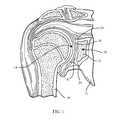
- a typical shoulder or glenohumeral jointis formed in a human body where the humerus 10 movably contacts the scapula 12 .
- the scapula 12includes a glenoid fossa 14 that forms a socket against which the head of the humerus 10 articulates.
- the scapula 12includes cartilage 16 that facilitates such articulation.
- Beneath the cartilageis subchondral bone 18 that forms a wall of a glenoid vault 20 that defines a cavity which contains cancellous bone 22 .
- the subchondral bone 18 that forms the glenoid vault 20defines a glenoid rim 24 at a periphery of the glenoid vault 20 that is attached to the cartilage 16 .
- the glenoid fossa 14may become worn, especially at its posterior and/or superior portions thereby causing severe shoulder pain and limiting the range of motion of the patient's shoulder joint.
- a shoulder arthroplastymay be performed. Arthroplasty is the surgical replacement of one or more bone structures of a joint with one or more prostheses.
- the conventional glenoid componenttypically provides a generally laterally or outwardly facing generally concave bearing surface against which a prosthetic humeral head (or, alternatively, the spared natural humeral head in the case of a glenoid hemi-arthroplasty) may bear during operation of the joint.
- the conventional glenoid componenttypically also includes a generally medially or inwardly projecting stem for fixing the glenoid component in a cavity constructed by suitably resecting the glenoid fossa 14 and suitably resecting cancellous bone 22 from the glenoid vault 20 .
- the goal of shoulder arthroplastyis to restore normal kinematics to the shoulder.
- known systemsattempt to replicate the normal kinematics by carefully controlling the geometry of the articulating surfaces in the joint as well as the positioning of the prostheses in the bones in which the prostheses are implanted.
- the articulating surface of a humeral componentis typically spherical and positioning of the humeral component is accomplished by using the anatomical neck of the humerus as the reference plane for reconstruction of the humeral head.
- the glenoid componentis positioned in the geometric center of the glenoid fossa.
- the geometric centeris established by generating a line from the most superior point of the glenoid rim to the most inferior point of the glenoid rim (“Saller's line”).
- a second lineis generated between the most posterior point of the glenoid rim and the most anterior point of the glenoid rim.
- the intersection of the two generated linesis considered to be the geometric center of the area circumscribed by the glenoid rim.
- FIG. 2depicts a sagittal view of the scapula 12 .
- FIG. 1depicts a sagittal view of the scapula 12 .
- Saller's line 30extends between the most superior point 32 of the glenoid rim 24 and the most inferior point 34 of the glenoid rim 24 .
- a second line 36extends from the most posterior point 38 of the glenoid rim 24 and the most anterior point 40 of the glenoid rim.
- the geometric center 42 of the glenoid fossa 14is located at the intersection of the line 36 and Saller's line 30 .
- anterior, posterior, superior, and inferiorare used with respect to the orientation of the scapula 12 as depicted in FIG. 2 .
- glenoid componentscan become loosened. Loosened components can result in increased pain for an individual. Correction of the problem, however, may be problematic. For example, replacement of components which are loosened may be complicated by a number of different glenoid deficiencies. Glenoid deficiencies may be classified as central (a void area in the central region of the glenoid fossa), peripheral (a void area in the glenoid rim area), or combined (a void area extending from the central region of the glenoid fossa to the glenoid rim area). Replacement of components in the presence of mild or moderate deficiencies, particularly when limited to the central region, may be accomplished using known components with or without bone grafting to fill remaining void areas. In cases involving large central deficiencies and combined deficiencies, however, other procedures such as allografting are required. Once the grafted material has been incorporated into the glenoid, a second surgery is performed to implant a replacement component into the allograft.
- a glenoid componentthat allows for establishing normal kinematics in revision procedures.
- a technique, instrumentation, and implantthat facilitates positioning of such a component even when the glenoid has a variety of deficiencies.
- a glenoid componentthat can be positioned in a manner that reduces the amount of bone that is required to be removed without overly complicating the implant procedure is also needed.
- the present inventionin one embodiment provides a method of implanting a revision glenoid component including accessing a previously implanted glenoid component in a scapula, removing the previously implanted glenoid component, identifying an inferior glenoid circle center of the scapula, preparing a glenoid fossa of the scapula to receive a revision glenoid component, selecting a revision glenoid component, and implanting the selected revision glenoid component based upon the identified inferior glenoid circle center in the prepared glenoid fossa.
- a method of implanting a revision glenoid componentincludes obtaining an image of a scapula, identifying an inferior glenoid circle center of the scapula based upon the image, selecting a revision glenoid component, removing a previously implanted glenoid component from the scapula, preparing a glenoid fossa of the scapula to receive a prosthesis, and implanting the selected revision glenoid component in the prepared glenoid fossa based upon the identified inferior glenoid circle center.
- FIG. 1depicts a coronal view of an anatomically normal shoulder joint.
- FIG. 2depicts a sagittal view of the shoulder joint of FIG. 1 ;
- FIG. 3depicts a front perspective view of a retroversion glenoid component that may be implanted in a scapula in accordance with principles of the invention
- FIG. 4depicts a front perspective view of the base of the retroversion glenoid component of FIG. 3 that may be implanted in a scapula in accordance with principles of the invention
- FIG. 5depicts a top plan view of the base of the retroversion glenoid component of FIG. 3 ;
- FIG. 6depicts a side cross-sectional view of the base of the retroversion glenoid component of FIG. 3 ;
- FIG. 7depicts a front perspective view of the articulating component of the retroversion glenoid component of FIG. 3 ;
- FIG. 8depicts a side cross-sectional view of the articulation component of the retroversion glenoid component of FIG. 3 ;
- FIG. 9depicts a side cross-sectional view of the retroversion glenoid component of FIG. 3 ;
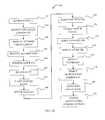
- FIG. 10depicts a medical procedure that may be used to implant the retroversion glenoid component base of FIG. 3 into a scapula using a kit that includes a guide pin and a combined reaming/planing tool;
- FIG. 11depicts a sagittal view of a scapula with an implanted glenoid component which exhibits severe central bone loss resulting in undesired movement of the implanted glenoid component and which has been accessed in accordance with the procedure of FIG. 10 ;
- FIG. 12depicts a sagittal view of the scapula of FIG. 11 after the previously implanted glenoid component has been removed;
- FIG. 13depicts a front perspective view of the scapula of FIG. 11 with a guide pin placement guide positioned to guide placement of the guide pin such that the guide pin is aligned with the glenoid axis of the scapula;
- FIG. 14depicts a side perspective view of the guide pin of FIG. 13 used to guide a combined reaming/planning device that may be included in a kit;
- FIG. 15depicts a partial bottom perspective view of the combined reaming/planning device of FIG. 14 showing a planning portion and a reaming portion;
- FIG. 16depicts a side perspective view of the scapula of FIG. 14 after a cavity has been reamed and after the glenoid has been repaired by using bone graft and a compactor to replace bone loss areas about the cavity;
- FIG. 17depicts the side perspective view of the scapula of FIG. 16 with the guide hole of a base component aligned with the guide pin such that the base component will be positioned in alignment with the glenoid axis of the scapula;
- FIG. 18depicts a sagittal plan view of the scapula of FIG. 17 with the base component rotated such that fasteners inserted into two of the fastener holes of the base can access a lateral pillar and a spina pillar of the scapula;
- FIG. 19depicts a cross-sectional view of the scapula of FIG. 18 with the coupling portion of the selected articulation component aligned with the receptacle of the base component;
- FIG. 20depicts a cross-sectional view of the scapula of FIG. 19 with the articulation component coupled with the base component such that the nadir of the articulation component is positioned at the glenoid axis of the scapula.
- FIG. 3depicts a retroversion glenoid component 100 .
- the glenoid component 100includes a base component 102 and an articulation component 104 .
- the base component 102includes a wall 106 which extends between a lip 108 and a bottom surface 110 .
- the wall 106defines a circular outer periphery that is slightly larger than the circular outer periphery of the wall 106 at the bottom surface 110 .
- the lip 108defines a receptacle 112 which is substantially cylindrical.
- the receptacle 112extends from the lip 108 to a lower surface 114 .
- Three fastener holes 116 , 118 , and 120extend through the lower surface 114 and the bottom surface 110 .
- a guide hole 122also extends through the lower surface 114 and the bottom surface 110 .
- the guide hole 122 and the receptacle 112are centrally located. Accordingly, the guide hole 122 , the receptacle 112 , and the outer wall 106 define a unitary axis 124 .
- the articulating component 104includes a spherical articulating surface 134 and a coupling portion 136 .
- the coupling portion 136is substantially cylindrical in shape and sized with a diameter slightly larger than the diameter of the receptacle 112 .
- the articulating surfaceis positioned with a nadir 138 located on a central axis 140 of the articulating component 104 . Accordingly, when the articulation component 104 is coupled with the base component 102 as depicted in FIG. 9 , the nadir 138 is located on the axis 124 of the base component.
- the glenoid component 100 in this embodimentis modular, but in other embodiments may be integrally formed. Integrally formed units may be made from a durable biocompatible plastic or any other suitable durable biocompatible material.
- the glenoid component 100may be made from a polyethylene.
- One particular polyethylene that is well suited for glenoid component 100is a high molecular weight polyethylene, for example ultra-high molecular weight polyethylene (“UHMWPE”).
- UHMWPEultra-high molecular weight polyethylene
- UHMWPEultra-high molecular weight polyethylene
- the various componentsmay be made from different materials.
- the articulating surface 134may be made from UHMWPE, while the coupling portion 136 and the base component 102 may be made from a suitable biocompatible metal such as, for example, a cobalt chromium alloy, a stainless steel alloy, a titanium alloy, or any other suitable durable material.
- the articulating surface 134is secured to the coupling portion 136 in any suitable manner.
- articulating surface 134may be bonded to coupling portion 136 , or articulating surface 134 could be made from polyethylene and compression molded to coupling portion 136 .
- the articulating surface 134may be glued to the coupling portion 136 , for example, an adhesive.
- articulating surface 134may be mechanically interlocked to the coupling portion 136 by taper locking or otherwise press-fitting the articulating surface 134 into the coupling portion 136 and the coupling portion 136 may include any other suitable interlocking features, for example, rib(s), lip(s), detent(s), and/or other protrusion(s) and mating groove(s), channel(s), or indent(s) (not shown).
- one or more of the outer wall 106 and the bottom surface 110may include a porous coating to facilitate bone in-growth into the glenoid component 100 .
- the porous coatingmay be any suitable porous coating and may for example be POROCOAT®, a product of Johnson & Johnson of New Brunswick, N.J. and more fully described in U.S. Pat. No. 3,855,638 to Pilliar, which is incorporated herein by reference.
- the glenoid component 100may be included in a kit incorporating instrumentation that may be used to facilitate implantation of the glenoid component 100 .
- instrumentationmay include reamers and guide pins, as discussed more fully below.
- the kitmay include base components having different heights and widths. Typical heights may range between 10 and 30 millimeters (mm).
- the kitmay further include articulation components having different diameters.
- a kitincludes articulation components having a variety of diameters ranging from about 23 mm to about 30 mm.
- each of the base components in a kithas a receptacle 112 that is shaped and dimensioned the same as the receptacle 112 of each of the other base components 102 while each of the articulation components 104 has a coupling portion 136 that is shaped and dimensioned the same as the coupling portion 136 of each of the other articulation components 104 . Accordingly, any of the articulation components 104 may be coupled with any of the base components 102 in the kit.
- a kit including the glenoid component 100may be used to implant the glenoid component 100 into a scapula that has previously received a glenoid component in accordance with a procedure 150 depicted in FIG. 10 .
- a scapulais accessed at block 152 in accordance with a desired surgical approach.
- the previously implanted glenoid componentis then removed at block 154 .
- the center of an inferior glenoid circleis identified for the scapula.
- the center of the inferior glenoid circlemay alternatively be identified prior to or after incising a patient with the aid of imaging or other techniques.
- a glenoid axiswhich extends through the center of the inferior glenoid circle and is perpendicular to the articulating surface of the glenoid is identified (block 158 ).
- the glenoid axismay extend through the scapula at locations other than the center of the inferior glenoid circle.
- the glenoid axismay be identified prior to or after incising a patient with the aid of imaging or other techniques.
- a guide pinis positioned in the scapula such that the longitudinal axis of the guide pin is coextensive with the glenoid axis (block 160 ).
- a circular cavityis then reamed in the glenoid (block 162 ) and the glenoid surface is planed (block 164 ).
- the circular cavityis preferably slightly larger than the diameter of the revision glenoid base component 102 . This allows for positioning of the base component 102 without placing stress on the glenoid which may be significantly compromised as discussed more fully below.
- a bone graft compactoris used over the guide pin, if needed, to fill in void areas of the glenoid which are not needed for receiving the revision glenoid component.
- the guide hole 122 of the base component 102is then aligned with and inserted onto the guide pin (block 168 ).
- the base component 102is then implanted in the prepared glenoid (block 170 ). Because the guide pin is positioned on the glenoid axis and because the guide pin is positioned within the guide hole 122 , using the guide pin ensures that the central axis 124 of the base component (see FIG. 6 ) is aligned with the glenoid axis.
- the base component 122may further be rotated about the guide pin to align one or more of the fastener holes 116 , 118 , and 120 with a respective one of the pillars of the scapula as described by A.
- the fastener holes 116 , 118 , and 120may be positioned so as to access the lateral and spina pillars. Rotation of the base component 102 is facilitated since the cavity in the glenoid is slightly larger than the base component 102 as discussed above.
- the guide pinmay then be removed (block 174 ) and one or more fasteners may be inserted through fastener holes 116 , 118 , and 120 to affix the base component 102 to the scapula (block 176 ).
- fastener holes 116 , 118 , and 120may be configured to allow for variable angle fastener placement to assist in achieving a firm fixation.
- a desired articulation componentis then obtained (block 178 ) and the coupling portion 136 is aligned with the receptacle 112 (block 180 ).
- the coupling portion 136is then moved into the receptacle 112 and the articulation component 104 is coupled to the base component 102 (block 182 ). Coupling may be facilitated by forming the coupling portion 136 and he receptacle 112 to form a friction fit, Morse taper, etc.
- the nadir 138will be aligned with the glenoid axis since the articulation component 104 is configured to couple with the base component 102 such that the nadir 138 is on the axis 140 as discussed above.
- FIGS. 11-20depict a scapula 50 at various points of the procedure 220 .
- the scapula 12is depicted after block 152 with a previously implanted glenoid component 52 .
- FIG. 12depicts the scapula 50 after the component 52 has been removed.
- the scapula 50 in FIG. 12exhibits severe central bone loss which has resulted in instability of the glenoid component 52 .
- the methods and devices disclosed hereinmay be used in performing a retroversion glenoid implantation in the presence of a variety of glenoid deficiencies including central, peripheral, and combined deficiencies ranging from mild to severe. Because the base component 102 is not press fit in to the scapula as discussed above, the potential of fracturing a portion of the scapula even in the presence of severe deficiencies is reduced.
- FIG. 13depicts a guide pin 190 and a guide pin placement guide 192 that may be included in a kit used to perform a revision glenoid component implantation procedure.
- the guide pin placement guide 192is positioned on the scapula 50 substantially centered upon the inferior glenoid circle.
- the guide pin 190is thus positioned in the scapula 50 with the longitudinal axis of the guide pin 190 aligned with the glenoid axis.
- FIG. 14depicts the scapula 50 with the guide pin 190 used to guide a combination reaming device 194 that may also be included in a kit in accordance with the present disclosure.
- the combination reaming device 194includes a shaft 196 and a working portion 198 .
- the shaft 196 and the working portion 198are cannulated to allow the guide pin 190 to be used to precisely position the combination device 194 .
- the working portion 198includes an outer planing portion 202 and a central reaming portion 204 .
- the planing portion 202 and the central reaming portion 204allow for simultaneous reaming and planing of the glenoid surface. Alternatively, two separate devices may be used sequentially.
- a kitincludes a cannulated compactor which is shaped like the reaming portion 204 .
- the cannulated compactormay be guided by the guide pin 190 to compact bone graft material 210 (see FIG. 16 ) while maintaining or finally forming a cavity 212 that is shaped slightly larger than the outer wall 106 of the base component 102 .
- FIG. 18depicts the base component 102 positioned such that a fastener passing through the fastener hole 116 may be fixed in the lateral pillar while a fastener passing through the fastener hole 118 may be fixed in the spina pillar.
- the base component 102may be positioned on bone graft 210 (see, e.g., FIG. 19 ), the base component may be solidly fixed to the scapula 50 . Thus, even when bone graft material 210 is used to fill in deficient areas of the scapula 50 , a second surgery is not required.
- the coupling portion 136 of the selected articulation component 104is aligned with the receptacle 112 of the base component 102 as depicted in FIG. 19 .
- the coupling portion 136is then moved into the receptacle 112 and the articulation component 104 is coupled to the base component 102 in any desired manner, such as by a Morse taper fit between the coupling portion 136 and the receptacle 112 , resulting in the configuration of FIG. 20 .
- the nadir 138is located on the glenoid axis since the base component 102 was fixed with the axis 124 of the guide hole 122 aligned with the glenoid axis as discussed above.
- a kitmay incorporate a number of different glenoid components. Each glenoid component in the kit may be of a different diameter. Additionally, the procedure 150 may be modified in a number of ways in addition to those discussed above. By way of example, while in the above example the glenoid component 100 was implanted with the nadir 138 aligned with the inferior glenoid circle center at block 182 , the nadir 138 may alternatively be offset from the inferior glenoid circle center.
- the nadir 138may be offset from the inferior glenoid circle center by about 1.1 mm in a direction superiorly and posteriorly from the inferior glenoid circle center by positioning the guide pin 190 at the offset location at block 160 .
- Imaging and computer based systemsmay be used to assist in the positioning of the glenoid component at this location.
- a glenoid component with a spherical articulating surfaceis implanted at or very near to the spinning point of a shoulder in a revision procedure. Because of the location of the glenoid component, a humeral component with a radius of curvature matched to the radius of curvature of the articulating surface may be used to provide a constrained fit.
- the term “matched”means a difference in the radii of curvature of the articulating surfaces of less than 2 mm.
Landscapes
- Health & Medical Sciences (AREA)
- Life Sciences & Earth Sciences (AREA)
- Animal Behavior & Ethology (AREA)
- General Health & Medical Sciences (AREA)
- Veterinary Medicine (AREA)
- Engineering & Computer Science (AREA)
- Biomedical Technology (AREA)
- Heart & Thoracic Surgery (AREA)
- Public Health (AREA)
- Oral & Maxillofacial Surgery (AREA)
- Orthopedic Medicine & Surgery (AREA)
- Surgery (AREA)
- Cardiology (AREA)
- Vascular Medicine (AREA)
- Transplantation (AREA)
- Dentistry (AREA)
- Nuclear Medicine, Radiotherapy & Molecular Imaging (AREA)
- Medical Informatics (AREA)
- Molecular Biology (AREA)
- Prostheses (AREA)
- Surgical Instruments (AREA)
Abstract
Description
Claims (20)
Priority Applications (10)
| Application Number | Priority Date | Filing Date | Title |
|---|---|---|---|
| US13/051,062US8551177B2 (en) | 2011-03-18 | 2011-03-18 | Revision glenoid kit |
| JP2013558134AJP6017468B2 (en) | 2011-03-18 | 2012-03-14 | Modified glenoid device and method |
| EP12760274.6AEP2685941B1 (en) | 2011-03-18 | 2012-03-14 | Revision glenoid device |
| PCT/US2012/029034WO2012129021A1 (en) | 2011-03-18 | 2012-03-14 | Revision glenoid device and method |
| AU2012231300AAU2012231300B2 (en) | 2011-03-18 | 2012-03-14 | Revision glenoid device and method |
| CN201280023915.3ACN103702637B (en) | 2011-03-18 | 2012-03-14 | Devices for correcting the glenoid |
| US14/027,907US10172715B2 (en) | 2011-03-18 | 2013-09-16 | Method of implanting a revision glenoid device |
| ZA2013/07756AZA201307756B (en) | 2011-03-18 | 2013-10-17 | Revision glenoid device and method |
| US16/214,676US11076963B2 (en) | 2011-03-18 | 2018-12-10 | Revision glenoid device |
| US17/388,918US12383408B2 (en) | 2011-03-18 | 2021-07-29 | Revision glenoid device method |
Applications Claiming Priority (1)
| Application Number | Priority Date | Filing Date | Title |
|---|---|---|---|
| US13/051,062US8551177B2 (en) | 2011-03-18 | 2011-03-18 | Revision glenoid kit |
Related Child Applications (1)
| Application Number | Title | Priority Date | Filing Date |
|---|---|---|---|
| US14/027,907DivisionUS10172715B2 (en) | 2011-03-18 | 2013-09-16 | Method of implanting a revision glenoid device |
Publications (2)
| Publication Number | Publication Date |
|---|---|
| US20120239156A1 US20120239156A1 (en) | 2012-09-20 |
| US8551177B2true US8551177B2 (en) | 2013-10-08 |
Family
ID=46829099
Family Applications (4)
| Application Number | Title | Priority Date | Filing Date |
|---|---|---|---|
| US13/051,062Active2031-06-05US8551177B2 (en) | 2011-03-18 | 2011-03-18 | Revision glenoid kit |
| US14/027,907Active2032-08-17US10172715B2 (en) | 2011-03-18 | 2013-09-16 | Method of implanting a revision glenoid device |
| US16/214,676Active2031-06-22US11076963B2 (en) | 2011-03-18 | 2018-12-10 | Revision glenoid device |
| US17/388,918Active2033-10-02US12383408B2 (en) | 2011-03-18 | 2021-07-29 | Revision glenoid device method |
Family Applications After (3)
| Application Number | Title | Priority Date | Filing Date |
|---|---|---|---|
| US14/027,907Active2032-08-17US10172715B2 (en) | 2011-03-18 | 2013-09-16 | Method of implanting a revision glenoid device |
| US16/214,676Active2031-06-22US11076963B2 (en) | 2011-03-18 | 2018-12-10 | Revision glenoid device |
| US17/388,918Active2033-10-02US12383408B2 (en) | 2011-03-18 | 2021-07-29 | Revision glenoid device method |
Country Status (7)
| Country | Link |
|---|---|
| US (4) | US8551177B2 (en) |
| EP (1) | EP2685941B1 (en) |
| JP (1) | JP6017468B2 (en) |
| CN (1) | CN103702637B (en) |
| AU (1) | AU2012231300B2 (en) |
| WO (1) | WO2012129021A1 (en) |
| ZA (1) | ZA201307756B (en) |
Cited By (5)
| Publication number | Priority date | Publication date | Assignee | Title |
|---|---|---|---|---|
| US9681960B2 (en) | 2014-05-16 | 2017-06-20 | Howmedica Osteonics Corp. | Guides for fracture system |
| US10575968B2 (en) | 2014-05-16 | 2020-03-03 | Howmedica Osteonics Corp. | Guides for fracture system |
| US20210236292A1 (en)* | 2013-03-12 | 2021-08-05 | DePuy Synthes Products, Inc. | System and method for implanting a secondary glenoid prosthesis |
| US11801151B2 (en) | 2019-03-12 | 2023-10-31 | Howmedica Osteonics Corp. | Anatomic shell 2-in-1 window trial |
| US12364539B2 (en) | 2021-09-30 | 2025-07-22 | Arthrex, Inc. | Orthopaedic planning systems, instrumentation and methods of repair |
Families Citing this family (38)
| Publication number | Priority date | Publication date | Assignee | Title |
|---|---|---|---|---|
| US20230080207A1 (en) | 2005-02-25 | 2023-03-16 | Shoulder Innovations, Inc. | Methods and devices for less invasive glenoid replacement |
| US8778028B2 (en) | 2005-02-25 | 2014-07-15 | Shoulder Innovations, Inc. | Methods and devices for less invasive glenoid replacement |
| FR2955247B1 (en) | 2010-01-21 | 2013-04-26 | Tornier Sa | GLENOIDAL COMPONENT OF SHOULDER PROSTHESIS |
| US8556901B2 (en) | 2009-12-31 | 2013-10-15 | DePuy Synthes Products, LLC | Reciprocating rasps for use in an orthopaedic surgical procedure |
| US8486076B2 (en)* | 2011-01-28 | 2013-07-16 | DePuy Synthes Products, LLC | Oscillating rasp for use in an orthopaedic surgical procedure |
| FR2971144A1 (en) | 2011-02-08 | 2012-08-10 | Tornier Sa | GLENOIDAL IMPLANT FOR SHOULDER PROSTHESIS AND SURGICAL KIT |
| US9421106B2 (en) | 2011-12-07 | 2016-08-23 | Howmedica Osteonics Corp. | Reverse shoulder baseplate with alignment guide for glenosphere |
| US8906102B2 (en)* | 2012-05-31 | 2014-12-09 | Howmedica Osteonics Corp. | Lateral entry insert for cup trial |
| US8663334B2 (en)* | 2012-05-31 | 2014-03-04 | Howmedica Osteonics Corp. | Lateral entry insert for cup trial |
| USD730522S1 (en) | 2013-03-11 | 2015-05-26 | Catalyst Orthopaedics Llc | Implant |
| US20170319348A1 (en) | 2015-08-10 | 2017-11-09 | Catalyst Orthoscience Inc. | Arthroplasty prostheses with multi-axis fixation |
| US10973646B2 (en) | 2013-03-11 | 2021-04-13 | Catalyst Orthoscience Inc. | Stabilized drill guide |
| US11007063B2 (en) | 2013-03-11 | 2021-05-18 | Catalyst Orthoscience Inc. | Offset reamers |
| WO2015018921A1 (en) | 2013-08-08 | 2015-02-12 | Universiteit Gent | Surgical guiding instrument |
| EP3057524B1 (en) | 2013-10-10 | 2019-11-20 | Imascap | Method for designing and producing a shoulder surgery guide |
| EP3925574A1 (en) | 2013-11-08 | 2021-12-22 | Imascap | Pre-operatively planned adaptive glenoid implants and method for planning its design |
| WO2015103090A1 (en) | 2014-01-03 | 2015-07-09 | Tornier, Inc. | Reverse shoulder systems |
| CN104000641B (en)* | 2014-06-13 | 2016-08-17 | 赵金忠 | A kind of shoulder joint bone grafting device under the conditions of Wicresoft |
| US10492926B1 (en) | 2014-09-04 | 2019-12-03 | Shoulder Innovations, Inc. | Alignment guide for humeral or femoral stem replacement prostheses |
| CA2983650C (en)* | 2015-04-24 | 2021-03-16 | Biomet Manufacturing, Llc | Patient-specific augmented glenoid systems and methods |
| US10722374B2 (en) | 2015-05-05 | 2020-07-28 | Tornier, Inc. | Convertible glenoid implant |
| EP3380025B1 (en)* | 2015-11-25 | 2021-01-27 | Subchondral Solutions, Inc. | Devices for repairing anatomical joint conditions |
| US10390972B2 (en) | 2016-01-15 | 2019-08-27 | Howmedica Osteonics Corp. | Humeral trial adaptor |
| EP3484416A1 (en)* | 2016-07-18 | 2019-05-22 | Catalyst Orthoscience Inc. | Arthroplasty prostheses with multi-axis fixation |
| WO2018182849A1 (en)* | 2017-03-30 | 2018-10-04 | Biomet Manufacturing, Llc | Patient specific reconstructive glenoid systems and methods |
| EP4520302A3 (en) | 2017-04-14 | 2025-04-16 | Shoulder Innovations, Inc. | Total shoulder prosthesis having inset glenoid implant convertible from anatomic to reverse |
| WO2018213094A1 (en)* | 2017-05-19 | 2018-11-22 | Biomet Manufacturing, Llc | Implant assembly tools |
| WO2019079104A2 (en) | 2017-10-16 | 2019-04-25 | Imascap Sas | Shoulder implants and methods of use and assembly |
| US12138172B2 (en) | 2018-04-30 | 2024-11-12 | Shoulder Innovations, Inc. | Inset/onlay glenoid, porous coated convertible glenoid, and humeral heads with textured undersides |
| US10583012B1 (en)* | 2018-09-07 | 2020-03-10 | Raphael S. F. Longobardi | Universal shoulder prosthesis system |
| EP3893787B1 (en) | 2018-12-12 | 2025-09-10 | Howmedica Osteonics Corp. | Bone density modeling and orthopedic surgical planning system |
| AU2020237088B2 (en) | 2019-03-11 | 2025-09-04 | Shoulder Innovations, Inc. | Total reverse shoulder systems and methods |
| EP3948780A1 (en) | 2019-03-29 | 2022-02-09 | Howmedica Osteonics Corp. | Pre-morbid characterization of anatomical object using statistical shape modeling (ssm) |
| JP7257546B2 (en) | 2019-05-13 | 2023-04-13 | ハウメディカ オステオニクス コーポレイション | Glenoid baseplate and implant assembly |
| EP3982848A1 (en) | 2019-08-09 | 2022-04-20 | Howmedica Osteonics Corp. | Apparatuses and methods for implanting glenoid prostheses |
| EP4013333A1 (en) | 2019-08-16 | 2022-06-22 | Howmedica Osteonics Corp. | Pre-operative planning of surgical revision procedures for orthopedic joints |
| WO2021086687A1 (en) | 2019-10-29 | 2021-05-06 | Tornier, Inc. | Use of bony landmarks in computerized orthopedic surgical planning |
| EP4231968A4 (en) | 2020-12-31 | 2024-08-07 | Howmedica Osteonics Corp. | Glenoid implants |
Citations (15)
| Publication number | Priority date | Publication date | Assignee | Title |
|---|---|---|---|---|
| US4030143A (en)* | 1975-01-31 | 1977-06-21 | National Research Development Corporation | Endoprosthetic bone joint devices |
| US5030219A (en) | 1990-01-22 | 1991-07-09 | Boehringer Mannheim Corporation | Glenoid component installation tools |
| US5180384A (en) | 1991-02-08 | 1993-01-19 | Mikhail Michael W E | Method for implanting a patellar prosthesis |
| US6364910B1 (en) | 2001-07-11 | 2002-04-02 | Biomet, Inc. | Method and apparatus for use of a glenoid component |
| US6379386B1 (en)* | 1997-09-09 | 2002-04-30 | Stryker Technologies Corporation | Anatomic glenoid shoulder prosthesis together with methods and tools for implanting same |
| US6679916B1 (en)* | 2002-04-29 | 2004-01-20 | Mark A. Frankle | Shoulder prosthesis system |
| US6699289B2 (en) | 2001-12-31 | 2004-03-02 | Depuy Orthopaedics, Inc. | Augmented glenoid component having an interrupted surface and associated method for securing the augmented glenoid component to a glenoid surface of a scapula |
| US6783549B1 (en)* | 2001-07-27 | 2004-08-31 | Biomet, Inc. | Modular humeral head resurfacing system |
| US20060069444A1 (en) | 2004-09-27 | 2006-03-30 | Deffenbaugh Daren L | Glenoid augment and associated method |
| US20060195194A1 (en) | 2005-02-25 | 2006-08-31 | Gunther Stephen B | Shoulder implant for glenoid replacement and methods of use thereof |
| US20070260321A1 (en) | 2006-05-02 | 2007-11-08 | Stchur Robert P | Conically-shaped glenoid implant with a prosthetic glenoid insert used in total shoulder arthroplasty and method |
| US7294133B2 (en)* | 2004-06-03 | 2007-11-13 | Zimmer Technology, Inc. | Method and apparatus for preparing a glenoid surface |
| US7329284B2 (en) | 2002-09-27 | 2008-02-12 | Depuy Products, Inc. | Concave resurfacing prosthesis |
| US7604665B2 (en) | 2006-09-20 | 2009-10-20 | Depuy Products, Inc. | Glenoid component for shoulder arthroplasty |
| US20110028977A1 (en) | 2009-07-31 | 2011-02-03 | Zimmer, Gmbh | Orthopaedic reamer |
Family Cites Families (51)
| Publication number | Priority date | Publication date | Assignee | Title |
|---|---|---|---|---|
| US2487203A (en) | 1946-07-17 | 1949-11-08 | Arthur L Wilber | Flexible drive for drills |
| CA962806A (en) | 1970-06-04 | 1975-02-18 | Ontario Research Foundation | Surgical prosthetic device |
| US4964865A (en) | 1988-02-03 | 1990-10-23 | Intermedics Orthopedics, Inc. | Glenoid prosthesis and method of use |
| US5080673A (en)* | 1988-02-03 | 1992-01-14 | Intermedics Orthopedics, Inc. | Glenoid prosthesis and method of use |
| US5324295A (en) | 1992-04-24 | 1994-06-28 | Shapiro Michael R | Drill guide for surgical pins |
| FR2704747B1 (en) | 1993-05-06 | 1995-07-21 | Medinov Sa | Support intended to receive a glenoid organ. |
| US5489310A (en) | 1994-06-27 | 1996-02-06 | Mikhail; W. E. Michael | Universal glenoid shoulder prosthesis and method for implanting |
| CA2166450C (en) | 1995-01-20 | 2008-03-25 | Ronald Salovey | Chemically crosslinked ultrahigh molecular weight polyethylene for artificial human joints |
| US6228900B1 (en) | 1996-07-09 | 2001-05-08 | The Orthopaedic Hospital And University Of Southern California | Crosslinking of polyethylene for low wear using radiation and thermal treatments |
| US5800551A (en)* | 1997-03-10 | 1998-09-01 | Biomet, Inc. | Apparatus and method for shoulder arthroplasty |
| JPH11127256A (en) | 1997-10-23 | 1999-05-11 | Matsushita Electric Ind Co Ltd | Electronic conference equipment |
| US5919195A (en) | 1998-01-20 | 1999-07-06 | Johnson & Johnson Professional, Inc. | Oblong acetabular component instrumentation |
| US6494913B1 (en)* | 1998-03-17 | 2002-12-17 | Acumed, Inc. | Shoulder prosthesis |
| US6010535A (en)* | 1998-04-30 | 2000-01-04 | Shah; Mrugesh K. | Joint replacement system |
| US6045302A (en) | 1999-03-04 | 2000-04-04 | Orr; Pat | Drill bit retriever device |
| CH693446A5 (en) | 1999-06-10 | 2003-08-15 | Precimed Sa | Hand tool with universal joint transmission has spring-loaded stud interacting by friction with cylindrical surfaces of spider |
| US6245074B1 (en) | 1999-09-01 | 2001-06-12 | Bristol-Myers Squibb Co. | Orthopaedic glenoid reamer |
| US20070055249A1 (en) | 2003-06-20 | 2007-03-08 | Jensen David G | Bone plates with intraoperatively tapped apertures |
| US6699269B2 (en) | 2001-04-30 | 2004-03-02 | Rohit K. Khanna | Selective brain and spinal cord hypothermia method and apparatus |
| US8062376B2 (en) | 2002-07-10 | 2011-11-22 | Biomet Manufacturing Corp. | Shoulder implant assembly |
| US7217271B2 (en) | 2002-09-13 | 2007-05-15 | Symmetry Medical, Inc. | Orthopaedic reamer driver for minimally invasive surgery |
| US7001392B2 (en) | 2003-01-29 | 2006-02-21 | Howmedica Osteonics Corp. | Apparatus and method for preparing bone for antirotational implantation of an orthopedic endoprosthesis |
| US8366713B2 (en) | 2003-03-31 | 2013-02-05 | Depuy Products, Inc. | Arthroplasty instruments and associated method |
| US7338498B2 (en) | 2003-03-31 | 2008-03-04 | Depuy Products, Inc. | Prosthetic implant, trial and associated method |
| FR2855743B1 (en)* | 2003-06-06 | 2006-02-10 | Biotechni | COTYLOID IMPLANT CUP INSERT FOR JOINT PROSTHESIS, COTYLOID IMPLANT AND ARTICULAR PROSTHESIS |
| US20050043805A1 (en)* | 2003-08-11 | 2005-02-24 | Chudik Steven C. | Devices and methods used for shoulder replacement |
| GB2406278B (en) | 2003-09-24 | 2007-08-29 | Biomet Merck Ltd | A reamer |
| US8303665B2 (en) | 2004-06-15 | 2012-11-06 | Tornier Sas | Glenoidal component, set of such components and shoulder prosthesis incorporating such a glenoidal component |
| US7927335B2 (en) | 2004-09-27 | 2011-04-19 | Depuy Products, Inc. | Instrument for preparing an implant support surface and associated method |
| US7922769B2 (en)* | 2004-09-27 | 2011-04-12 | Depuy Products, Inc. | Modular glenoid prosthesis and associated method |
| DE102004053606A1 (en) | 2004-11-05 | 2006-05-11 | Plus Orthopedics Ag | glenoid prosthesis |
| US8778028B2 (en) | 2005-02-25 | 2014-07-15 | Shoulder Innovations, Inc. | Methods and devices for less invasive glenoid replacement |
| US20070038302A1 (en) | 2005-08-15 | 2007-02-15 | Biomet Manufacturing Corp. | Method and apparatus for the preparation of an inlaid glenoid |
| GB0519994D0 (en)* | 2005-10-01 | 2005-11-09 | Depuy Ireland Ltd | Humeral component of a shoulder joint prosthesis |
| US7959680B2 (en)* | 2006-02-02 | 2011-06-14 | Biomet Manufacturing Corp. | Method and apparatus for performing a shoulder implant procedure |
| US8425614B2 (en) | 2006-03-20 | 2013-04-23 | Biomet Manufacturing Corp. | Modular center pegged glenoid |
| US20070251356A1 (en) | 2006-04-26 | 2007-11-01 | Tribby Jerry W | Spark plug wrench for confined spaces |
| US20110012318A1 (en) | 2008-02-27 | 2011-01-20 | Titanium Truck Technologies Pty Ltd. | Hanger for a skateboard truck |
| US8241289B2 (en) | 2008-04-28 | 2012-08-14 | Depuy (Ireland) | Manual glenoid reamer |
| US20090270993A1 (en)* | 2008-04-28 | 2009-10-29 | Robin Maisonneuve | Orientation feature on eccentric glenosphere |
| US8197487B2 (en) | 2008-04-28 | 2012-06-12 | Depuy (Ireland) Ltd. | Reaming guide alignment instrument |
| US8241365B2 (en)* | 2008-12-23 | 2012-08-14 | Depuy Products, Inc. | Shoulder prosthesis with vault-filling structure having bone-sparing configuration |
| FR2940607B1 (en)* | 2008-12-29 | 2012-04-06 | Didier Capon | GLENOIDAL IMPLANT COMPRISING A CUP FOR COOPERATING WITH A PROTHETIC HUMERAL HEAD |
| FR2944694B1 (en)* | 2009-04-22 | 2012-05-18 | Tornier Sa | DEVICE FOR FIXING THE GLENE OF A GLENOIDAL ARTICULAR COMPONENT FOR A SHOULDER PROSTHESIS AND CORRESPONDING SHOULDER PROSTHESIS |
| CN102458270A (en)* | 2009-06-24 | 2012-05-16 | 定制Med整形(私人)有限公司 | A positioning guide and a bone cutting guide system |
| US9549820B2 (en)* | 2009-06-25 | 2017-01-24 | Zimmer, Inc. | Glenoid implant with synthetic labrum |
| EP2451365B1 (en) | 2009-07-10 | 2015-07-01 | Kirk Promotion LTD. | Hip joint instrument |
| US8480750B2 (en) | 2010-11-24 | 2013-07-09 | DePuy Synthes Products, LLC | Modular glenoid prosthesis |
| US8454702B2 (en)* | 2011-01-20 | 2013-06-04 | Biomet Manufacturing Corp. | Reverse shoulder prosthetic |
| US8764836B2 (en)* | 2011-03-18 | 2014-07-01 | Lieven de Wilde | Circular glenoid method for shoulder arthroplasty |
| US10039556B2 (en)* | 2011-11-10 | 2018-08-07 | David Michael Burt | Arthroscopic total shoulder arthroplasty |
- 2011
- 2011-03-18USUS13/051,062patent/US8551177B2/enactiveActive
- 2012
- 2012-03-14WOPCT/US2012/029034patent/WO2012129021A1/enactiveApplication Filing
- 2012-03-14AUAU2012231300Apatent/AU2012231300B2/enactiveActive
- 2012-03-14CNCN201280023915.3Apatent/CN103702637B/enactiveActive
- 2012-03-14JPJP2013558134Apatent/JP6017468B2/enactiveActive
- 2012-03-14EPEP12760274.6Apatent/EP2685941B1/enactiveActive
- 2013
- 2013-09-16USUS14/027,907patent/US10172715B2/enactiveActive
- 2013-10-17ZAZA2013/07756Apatent/ZA201307756B/enunknown
- 2018
- 2018-12-10USUS16/214,676patent/US11076963B2/enactiveActive
- 2021
- 2021-07-29USUS17/388,918patent/US12383408B2/enactiveActive
Patent Citations (16)
| Publication number | Priority date | Publication date | Assignee | Title |
|---|---|---|---|---|
| US4030143A (en)* | 1975-01-31 | 1977-06-21 | National Research Development Corporation | Endoprosthetic bone joint devices |
| US5030219A (en) | 1990-01-22 | 1991-07-09 | Boehringer Mannheim Corporation | Glenoid component installation tools |
| US5180384A (en) | 1991-02-08 | 1993-01-19 | Mikhail Michael W E | Method for implanting a patellar prosthesis |
| US6379386B1 (en)* | 1997-09-09 | 2002-04-30 | Stryker Technologies Corporation | Anatomic glenoid shoulder prosthesis together with methods and tools for implanting same |
| US6364910B1 (en) | 2001-07-11 | 2002-04-02 | Biomet, Inc. | Method and apparatus for use of a glenoid component |
| US6783549B1 (en)* | 2001-07-27 | 2004-08-31 | Biomet, Inc. | Modular humeral head resurfacing system |
| US6699289B2 (en) | 2001-12-31 | 2004-03-02 | Depuy Orthopaedics, Inc. | Augmented glenoid component having an interrupted surface and associated method for securing the augmented glenoid component to a glenoid surface of a scapula |
| US6679916B1 (en)* | 2002-04-29 | 2004-01-20 | Mark A. Frankle | Shoulder prosthesis system |
| US7329284B2 (en) | 2002-09-27 | 2008-02-12 | Depuy Products, Inc. | Concave resurfacing prosthesis |
| US7294133B2 (en)* | 2004-06-03 | 2007-11-13 | Zimmer Technology, Inc. | Method and apparatus for preparing a glenoid surface |
| US20060069444A1 (en) | 2004-09-27 | 2006-03-30 | Deffenbaugh Daren L | Glenoid augment and associated method |
| US20060195194A1 (en) | 2005-02-25 | 2006-08-31 | Gunther Stephen B | Shoulder implant for glenoid replacement and methods of use thereof |
| US20100087876A1 (en) | 2005-02-25 | 2010-04-08 | Shoulder Innovations, Llc | Methods for less invasive glenoid replacement |
| US20070260321A1 (en) | 2006-05-02 | 2007-11-08 | Stchur Robert P | Conically-shaped glenoid implant with a prosthetic glenoid insert used in total shoulder arthroplasty and method |
| US7604665B2 (en) | 2006-09-20 | 2009-10-20 | Depuy Products, Inc. | Glenoid component for shoulder arthroplasty |
| US20110028977A1 (en) | 2009-07-31 | 2011-02-03 | Zimmer, Gmbh | Orthopaedic reamer |
Non-Patent Citations (57)
| Title |
|---|
| Antuna et al., "Glenoid revision surgery after total shoulder arthroplasty," Journal of Shoulder Elbow Surgery, 2001, pp. 217-224, vol. 10, Rochester, MN (8 pages). |
| Bey, Michael J., et al., "Measuring Dynamic In-Vivo Glenohumeral Joint Kinematics: Technique and Preliminary Results," Journal of Biomechanics 41 (2008), pp. 711-714. (4 pages). |
| Boileau P, Walch G., "The three dimensional geometry of the proximal humerus. Implications for the surgical technique and prosthetic design." J. Bone Joint Surg Br 1997;79-B:857-65. doi:10.1302/0301-620X.79B5.7579 (9 pages). |
| Boyer PJ, Massimini DF, Gill TJ, Papannagari R, Stewart SL, Warner JP, Li G., "In vivo articular cartilage contact at the glenohumeral joint: preliminary report." J. Orthop Sci. 2008;13:359-65.doi:10.1007/s00776-008-1237-3 (7 pages). |
| Bryce CD, Davison AC, Lewis GS, Wang , Flemming DJ, Armstrong AD., "Two dimensional glenoid version measurements vary with coronal and sagittal scapular rotation." J Bone Joint Surg Am. 2010;92-692-9.doi.10.2106/JBJS.I.00177 (8 pages). |
| Chant, Chris B., et al., "Humeral Head Retroversion in Competitive Baseball Players and Its Relationship to Glenohumeral Rotation Range of Motion," Journal of Orthopaedic & Sports Physical Therapy, Sep. 2007, vol.37, No. 9, pp. 514-520. (7 pages). |
| Codsi et al., "Normal glenoid vault anatomy and validation of a novel glenoid implant shape," Journal of Shoulder Elbow Surgery, May/Jun. 2008, pp. 471-478, vol. 17, Austria (8 pages). |
| Conzen, Annemarie and Eckstein, Felix, MD, "Quantitative Determination of Articular Pressure in the Human Shoulder Joint," Journal of Shoulder and Elbow Surgery, vol. 9, No. 3, May/Jun. 2000, pp. 196-204. (9 pages). |
| Couteau B, Mansat , Darmana R, Mansat M., Egan J., "Morphological and mechanical analysis of the glenoid by 3D geometric reconstruction using computed tomography." Clin Biomech 2000;15(suppl1):8-12.doi:10.1016/50268-0033(00)00052-8 (5 pages). |
| Couteau B, Mansat P, Mansat M, Darmana R, Egan J., "In vivo characterization of glenoid with use of computed tomography." J Shoulder Elbow Surg 2001;116-22 (7 pages). |
| Couteau B, Mansat P. Estivales E, Darmana R. Mansat M., Egan J., "Finite element analysis of the mechanical behavior of a scapula implanted with a glenoid prosthesis." Clin Biomech 2001;16:566-75.doi:10.1016/50268-0033(01)00029-8 (10 pages). |
| De Wilde LF, Verstraeten T, Speeckaert W, Karelse A., "Reliability of the glenoid plane." J Shoulder Elbow Surg. 2010;19:414-22. doi:10.1016/j.jse.2009.10.005. (9 pages). |
| De Wilde, L.F., et al., "About the Variability of the Shape of the Glenoid Cavity," Surgical and Radiologic Anatomy (2004) 26; pp. 54-59. (6 pages). |
| De Wilde, Lieven F. MD, et al., "Glenohumeral Relationship in the Transverse Plane of the Body," Journal of Shoulder and Elbow Surgery, vol. 12, No. 3, May/Jun. 2003, pp. 260-267. (8 pages). |
| Erichsen, "Injuries of the Nervous System on Railway and Other Injuries of the Nervous System", The Classic Article in Clinical Orthopaedics and Related Research, Mar. 1997, pp. 47-51, No. 458, Walton and Moberly, London (5 pages). |
| Fleiss, Joseph L., "Analysis of Data From Multiclinic Trials," Controlled Clinical Trials 7: 267-275 (1986). (9 pages). |
| Frederick et al. "Shoulder Arthroplasty: The Socket Perspective," J Shoulder Elbow Surg. 2007; 16:241S-247S.* |
| Graichen H, Hinterwimmer S, von Eisenhart-Rothe R, Vogl T. Englmeier KH, Eckstein F., "Effect of abducting and adducting muscle acitivity on glenohumeral translation, scapular kinematics and subacromial space width in vivo." Journal of Biomechanics 2005;38:755-60. doi:10.1016/j.jbiomech.2004.05.020. (6 pages). |
| Graichen H, Stammberger T. Bonel H, Karl-Hans E, Reiser M, Eckstein F., "Glenohumeral translation during active and passive elevation of the shoulder-a 3D open-MRI study." Journal of Biomechanics 2000;33:609-13.doi:10.1016/S0021-9290(99)00209-2. (5 pages). |
| Harryman DT, Sidles JA, Harris SL, Lippitt SB, Matsen FA., "The effect of articular conformity and the size of the humeral head component on laxity and motion after glenohumeral arthroplasty." J. Bone Joint Surg Am 1995;77-A:555-63.No doi found. (10 pages). |
| Hertel, Ralph M.D., "Geometry of the Proximal Humerus and Implications for Prosthetic Design," Journal of Shoulder and Elbow Surgery, Jul./Aug. 2002, vol. 11, No. 4, pp. 331-338. (8 pages). |
| Huysmans PE, Haen PS, Kidd M, Dhert WJ, Willems JW., "The shape of the inferior part of the glenoid: a cadaveric study." J Shoulder Elbow Surg. 15(6):759-63. doi:10.1016/j.jse.2005.09.001 (5 pages). |
| Iannotti JP, Gabriel JP, Schneck SL, Evans BG, Misra S., "The normal glenohumeral relationships. An anatomical study of one hundred and forty shoulder." J. Bone Joint Surg Am. 1992;74(4); 491-500. No doi found. (11 pages). |
| Jeske, H.C. et al., "Normal glenoid rim anatomy and the reliability of shoulder instability measurements based on intrasite correlation," Surg. Radiol. Anat., vol. 31, pp. 623-625, Mar. 2009 (3 pages). |
| Karduna AR, Williams GR, Williams JL, Ianotti JP., "Glenohumeral Joint translations before and after total shoulder arthroplasty." J Bone Joint Surg 1997;79-A,1166-74. No doi found (10 pages). |
| Karelse et al., "The Pillars of the Scapula", Clinical Anatomy, 2007, pp. 392-399, vol. 20, Belgium (8 pages). |
| Lee SB, Kim KJ, O'Driscoll SW, Morrey BF, An KN., "Dynamic glenohumeral stability provided by the rotator cuff muscles in the mid-range and end-range of motion." A study in cadavera. J. Bone Joint Surg Am. 2000;82(6):849-57. No doi found (10 pages). |
| Lewis GS, Bryce CD, Davison AC, Hollenbeak CS, Piazza SJ, Armstrong AD., "Location of the optimized centerline of the glenoid vault: a comparison of two operative techniques with use of three-dimensional computer modeling." J Bone Joint Surg Am, 2010;92:1188-94. doi:10-2106/JBJS.I.00131. (8 pages). |
| Mahfouz M, Nicholson G, Komistek R, Hovis D, Kubo M., "In vivo determination of the dynamics of normal, rotator cuff-deficient, total, and reverse replacement shoulders." J Bone Joint Surg Am. 2005;87 Suppl 2:107-13. doi:10.2106/JBJS.E.00483 (8 pages). |
| Mansat, M. and Fourcade, D., "Preoperative Planning in Shoulder Prosthesis," Acta Orthopaedica Belgica (1995) vol. 61-Suppl. Jan. 1995. (6 pages). |
| Massimini DF, Li G, Warner JP., "Glenohumeral contact kinematics in patients after total shoulder arthroplasty." J Bone Joint Surg Am. Apr. 2010;92(4):916-26. doi:10.2106/JBJS.H.01610. (12 pages). |
| Matsen FA., "Early effectiveness of shoulder arthroplasty for patients who have primary glenohumeral degenerative joint disease." J Bone and Joint Surg 1996;78-A:260-4. No doi found. (6 pages). |
| Middernacht, Bart, MD, et al., "Consequences of Scapular Anatomy for Reversed Total Shoulder Arthroplasty,"Clinical Orthopaedics and Related Research (2008) 466: 1410-1418. (9 pages). |
| Moon, P. and Spencer, D.E., Rectangular Coordinates (x,y,z). Field Theory Handbook, Including Coordinate Systems, Differential Equations, and Their Solutions (1988), New York: Springer-Verlag, pp. 9-11 (Table 1.01). (3 pages). |
| Nyffeler RW, Sheikh R, Atkinson TS, Jacob HA, Favre P, Gerber C., "Effects of glenoid component version on humeral head displacement and joint reaction forces: an experimental study." J Shoulder Elbow Surg. 2006;15:625-9. doi:10.1016/j.jse.2005.09.016. (5 pages). |
| Nyffeler RW, Werner CM, Sukthankar A, Schmid MR, Gerber C., "Association of a large lateral extension of the acromion with rotator cuff tears." J. Bone Joint Surg AM. 2006;88-800-5. No doi found (7 pages). |
| Pappas GP, Blemker SS, Beaulieu CF, McAdams TR, Whalen ST, Gold GE., "In vivo anatomy of the Neer and Hawkins sign positions for shoulder impingement." J Shoulder Elbow Surg 2006;15:40-9. doi:10.1016/j.jse.2005.04.007. (10 pages). |
| Pearl ML, Krurtz S., "Geometric analysis of commonly used prosthetic systems for proximal humeral replacement." J Bone Joint Surg 1999;81-A:660-71. No doi found (13 pages). |
| Pearl, Michael L., M.D. and Volk, Albert G., M.D., "Coronal Plane Geometry of the Proximal Humerus Relevant to Prosthetic Arthroplasty, Journal of Shoulder and Elbow Surgery," vol. 5, No. 4, Jul./Aug. 1996, pp. 320-326. (7 pages). |
| Pearl, ML and Volk, AG, "Retroversion of the Proximal Humerus in Relationship to Prosthetic Replacement Arthroplasty," Journal of Shoulder and Elbow Surgery, Jul. 1995, vol. 4, No. 4, pp. 286-289. (4 pages). |
| Randelli, M., M.D. and Gambrioli, P.L., M.D., "Glenohumeral Osteometry by Computed Tomography in Normal and Unstable Shoulders," Clinical Orthopaedics and Related Research, No. 208, Jul. 1986, pp. 151-156. (6 pages). |
| Robertson, Douglas D., M.D., et al., "Three-Dimensional Analysis of the Proximal Part of the Humerus: Relevance to Arthroplasty," The Journal of Bone and Joint Surgery, vol. 82-A,No. 11, Nov. 2000, pp. 1594-1602. (9 pages). |
| Rougraff, Bruce T., M.D., et al., "Does Length of Symptoms Before Diagnosis of Sarcoma Affect Patient Survival?" Clinical Orthopaedics and Related Research (2007), No. 462, pp. 181-189. (9 pages). |
| Scalise JJ, Codsi MJ, Bryan J, Brems JJ, Iannotti JP., "The influence of three-dimensional computed tomography images of the shoulder in preoperative planning for total shoulder arthroplasty." J Bone Joint Surg Am. 2008;90:2438-45.doi:10.2106/JBJS.G.01341. (9 pages). |
| Schiffern SC, Rozencwaig R, Antoniou J, Richardson ML, Matsen FA III., "Anteroposterior centering of the humeral head on the glenoid in vivo." Am J Sports Med. 2002;30(3):382-7. No doi found. (7 pages). |
| Shrout, Patrick E. and Fleiss, Jospeh L., "Intraclass Correlations: Uses in Assessing Rater Reliability," Psychological Bulletin, 1979, vol. 86, No. 2, pp. 420-428. (9 pages). |
| Soslowsky LJ, Flatow EL, Bigliani U, Pawluk RJ, Ateshian GA, Mow VC., "Quantitation of in situ contact areas at the glenohumeral joint: a biomechanical study." J Orthop Res. 1992;10:524-34. doi:10.1002/jor.1100100407. (11 pages). |
| Soslowsky, Louis J., Ph.D. et al, "Articular Geometry of the Glenohumeral Joint," Clinical Orthopaedics and Related Research, No. 285, Dec. 1992, pp. 181-190. (10 pages). |
| Takase K, Yamamoto K, Imakiire A, Burkhead WZ Jr., "The radiographic study in the relationship of the glenohumeral joint." J Orthop Res. 2004;22:298-305. doi:10.1016/50736-0266(03)00187-6 (8 pages). |
| Tetreault, Patrice, et al., "Glenoid Version and Rotator Cuff Tears," Journal of Orthopaedic Research 22 (2004) pp. 202-207. (6 pages). |
| Tokgoz N, Kanatli U, Voyvoda NK, Gultekin S, Bolukbasi S, Tali ET., "The relationship of glenoid and humeral version with supraspinatus tendon tears." Skeletal Radion. 2007;36:509-14. No doi found. (6 pages). |
| Warner, Jon J.P., M.D. et al, "Articular Contact Patterns of the Normal Glenohumeral Joint," Journal of Shoulder and Elbow Surgery, Jul./Aug. 1998, vol. 7, No. 4, pp. 381-388. ( 8 pages). |
| Werner CML, Weishaupt D, Blumenthal S, Curt A, Favre P, Gerber C., "Effect of experimental suprascapular nerve block on active glenohumeral translations in vivo." J Orthop Res 2006;24:491-500. doi:10.1002/jor.20011. (10 pages). |
| Westerhoff, P., et al., "In Vivo Measurement of Shoulder Joint Loads During Activities of Daily Living," Journal of Biomechanics 42 (2009), pp. 1840-1849. (10 pages). |
| Williams, Gerald R., Jr., M.D., and Iannotti, Joseph P., M.D. PhD., "Options for Glenoid Bone Loss: Composites of Prosthetics and Biologics," Journal of Shoulder and Elbow Surgery, Sep./Oct. 2007, vol. 16, No. 5S, pp. 267S-272S. (6 pages). |
| Wirth, Michael A. and Rockwood, Charles A., Jr., "Current Concepts Review-Complications of Total Shoulder-Replacement Arthroplasty," Journal of Bone & Joint Surgery, Apr. 1996, vol. 78-A, No. 4, pp. 603-616. (15 pages). |
| Wirth, Michael A., M.D. and Rockwood, Charles A., Jr., M.D., "Complications of Shoulder Arthroplasty," Clinical Orthopaedics and Related Research, Oct. 1994, No. 307, pp. 47-69. ( 23 pages). |
Cited By (6)
| Publication number | Priority date | Publication date | Assignee | Title |
|---|---|---|---|---|
| US20210236292A1 (en)* | 2013-03-12 | 2021-08-05 | DePuy Synthes Products, Inc. | System and method for implanting a secondary glenoid prosthesis |
| US12208015B2 (en)* | 2013-03-12 | 2025-01-28 | DePuy Synthes Products, Inc. | System and method for implanting a secondary glenoid prosthesis |
| US9681960B2 (en) | 2014-05-16 | 2017-06-20 | Howmedica Osteonics Corp. | Guides for fracture system |
| US10575968B2 (en) | 2014-05-16 | 2020-03-03 | Howmedica Osteonics Corp. | Guides for fracture system |
| US11801151B2 (en) | 2019-03-12 | 2023-10-31 | Howmedica Osteonics Corp. | Anatomic shell 2-in-1 window trial |
| US12364539B2 (en) | 2021-09-30 | 2025-07-22 | Arthrex, Inc. | Orthopaedic planning systems, instrumentation and methods of repair |
Also Published As
| Publication number | Publication date |
|---|---|
| US11076963B2 (en) | 2021-08-03 |
| US10172715B2 (en) | 2019-01-08 |
| ZA201307756B (en) | 2015-04-29 |
| EP2685941A4 (en) | 2014-07-30 |
| US20120239156A1 (en) | 2012-09-20 |
| US20210353424A1 (en) | 2021-11-18 |
| US12383408B2 (en) | 2025-08-12 |
| JP6017468B2 (en) | 2016-11-02 |
| US20190125542A1 (en) | 2019-05-02 |
| EP2685941B1 (en) | 2015-09-16 |
| CN103702637A (en) | 2014-04-02 |
| CN103702637B (en) | 2016-03-30 |
| WO2012129021A1 (en) | 2012-09-27 |
| JP2014515643A (en) | 2014-07-03 |
| EP2685941A1 (en) | 2014-01-22 |
| AU2012231300B2 (en) | 2016-08-04 |
| US20140018927A1 (en) | 2014-01-16 |
| AU2012231300A1 (en) | 2013-10-17 |
Similar Documents
| Publication | Publication Date | Title |
|---|---|---|
| US12383408B2 (en) | Revision glenoid device method | |
| US9226830B2 (en) | Device and method for retroversion correction for shoulder arthroplasty | |
| US11369390B2 (en) | Method using a combination reamer/drill bit for shoulder arthroplasty | |
| US20220362025A1 (en) | Prosthetic implants including a frame for fixation to bone and related methods | |
| US20250177156A1 (en) | Augmented glenoid with groove | |
| US11865016B2 (en) | Shoulder arthroplasty system method with combination humeral sizer, trial, and guide | |
| EP2623050A1 (en) | Instrument for use in shoulder arthroplasty | |
| WO2015134626A2 (en) | Shoulder prosthesis | |
| US20250009521A1 (en) | Stemless implant assemblies with screw fixation | |
| US20240050235A1 (en) | Anatomically shaped stemless shoulder for total shoulder replacement and reverse total shoulder |
Legal Events
| Date | Code | Title | Description |
|---|---|---|---|
| AS | Assignment | Owner name:DEPUY PRODUCTS, INC, INDIANA Free format text:ASSIGNMENT OF ASSIGNORS INTEREST;ASSIGNORS:DE WILDE, LIEVEN;LAPPIN, KYLE;SIGNING DATES FROM 20110314 TO 20110316;REEL/FRAME:025985/0973 | |
| AS | Assignment | Owner name:DEPUY SPINE, LLC, MASSACHUSETTS Free format text:ASSIGNMENT OF ASSIGNORS INTEREST;ASSIGNOR:DEPUY PRODUCTS, INC.;REEL/FRAME:030679/0948 Effective date:20121230 Owner name:HAND INNOVATIONS LLC, FLORIDA Free format text:ASSIGNMENT OF ASSIGNORS INTEREST;ASSIGNOR:DEPUY SPINE, LLC;REEL/FRAME:030680/0385 Effective date:20121230 Owner name:DEPUY SYNTHES PRODUCTS, LLC, MASSACHUSETTS Free format text:CHANGE OF NAME;ASSIGNOR:HAND INNOVATIONS LLC;REEL/FRAME:030680/0913 Effective date:20121231 | |
| STCF | Information on status: patent grant | Free format text:PATENTED CASE | |
| FPAY | Fee payment | Year of fee payment:4 | |
| MAFP | Maintenance fee payment | Free format text:PAYMENT OF MAINTENANCE FEE, 8TH YEAR, LARGE ENTITY (ORIGINAL EVENT CODE: M1552); ENTITY STATUS OF PATENT OWNER: LARGE ENTITY Year of fee payment:8 | |
| MAFP | Maintenance fee payment | Free format text:PAYMENT OF MAINTENANCE FEE, 12TH YEAR, LARGE ENTITY (ORIGINAL EVENT CODE: M1553); ENTITY STATUS OF PATENT OWNER: LARGE ENTITY Year of fee payment:12 |