US8551100B2 - Instrumentation for knee resection - Google Patents
Instrumentation for knee resectionDownload PDFInfo
- Publication number
- US8551100B2 US8551100B2US11/337,861US33786106AUS8551100B2US 8551100 B2US8551100 B2US 8551100B2US 33786106 AUS33786106 AUS 33786106AUS 8551100 B2US8551100 B2US 8551100B2
- Authority
- US
- United States
- Prior art keywords
- guide
- rail
- main body
- axis
- cutting
- Prior art date
- Legal status (The legal status is an assumption and is not a legal conclusion. Google has not performed a legal analysis and makes no representation as to the accuracy of the status listed.)
- Expired - Fee Related, expires
Links
Images


Classifications
- A—HUMAN NECESSITIES
- A61—MEDICAL OR VETERINARY SCIENCE; HYGIENE
- A61B—DIAGNOSIS; SURGERY; IDENTIFICATION
- A61B17/00—Surgical instruments, devices or methods
- A61B17/16—Instruments for performing osteoclasis; Drills or chisels for bones; Trepans
- A61B17/17—Guides or aligning means for drills, mills, pins or wires
- A61B17/1739—Guides or aligning means for drills, mills, pins or wires specially adapted for particular parts of the body
- A61B17/1764—Guides or aligning means for drills, mills, pins or wires specially adapted for particular parts of the body for the knee
- A—HUMAN NECESSITIES
- A61—MEDICAL OR VETERINARY SCIENCE; HYGIENE
- A61B—DIAGNOSIS; SURGERY; IDENTIFICATION
- A61B17/00—Surgical instruments, devices or methods
- A61B17/14—Surgical saws
- A61B17/142—Surgical saws with reciprocating saw blades, e.g. with cutting edges at the distal end of the saw blades
- A—HUMAN NECESSITIES
- A61—MEDICAL OR VETERINARY SCIENCE; HYGIENE
- A61B—DIAGNOSIS; SURGERY; IDENTIFICATION
- A61B17/00—Surgical instruments, devices or methods
- A61B17/14—Surgical saws
- A61B17/15—Guides therefor
- A61B17/154—Guides therefor for preparing bone for knee prosthesis
- A61B17/155—Cutting femur
- A—HUMAN NECESSITIES
- A61—MEDICAL OR VETERINARY SCIENCE; HYGIENE
- A61B—DIAGNOSIS; SURGERY; IDENTIFICATION
- A61B17/00—Surgical instruments, devices or methods
- A61B17/14—Surgical saws
- A61B17/15—Guides therefor
- A61B17/154—Guides therefor for preparing bone for knee prosthesis
- A61B17/157—Cutting tibia
- A—HUMAN NECESSITIES
- A61—MEDICAL OR VETERINARY SCIENCE; HYGIENE
- A61B—DIAGNOSIS; SURGERY; IDENTIFICATION
- A61B17/00—Surgical instruments, devices or methods
- A61B17/16—Instruments for performing osteoclasis; Drills or chisels for bones; Trepans
- A61B17/1662—Instruments for performing osteoclasis; Drills or chisels for bones; Trepans for particular parts of the body
- A61B17/1675—Instruments for performing osteoclasis; Drills or chisels for bones; Trepans for particular parts of the body for the knee
- A—HUMAN NECESSITIES
- A61—MEDICAL OR VETERINARY SCIENCE; HYGIENE
- A61B—DIAGNOSIS; SURGERY; IDENTIFICATION
- A61B17/00—Surgical instruments, devices or methods
- A61B17/02—Surgical instruments, devices or methods for holding wounds open, e.g. retractors; Tractors
Definitions
- the present teachingsrelate to orthopedic surgery, and particularly to, knee resection procedures and instruments.
- the human anatomyincludes many articulating portions.
- the femur and the tibiaform a knee joint in the human anatomy.
- the femur and tibiaarticulate relative to one another during many activities, such as walking or kneeling. Nevertheless, over time, disease and/or injury can deteriorate the knee joint, such that articulation of the joint becomes painful or impractical.
- anatomical replacementsparticularly prosthetics, can be placed in the femur, tibia, or both.
- the prostheticsmay replace the articulating portions and allow a substantially natural articulation of the joint. Replacing the damaged portions allow for a much easier and more practical articulation of the knee joint to assist the individual in returning to a more natural lifestyle.
- the original or natural anatomyincluding boney portions
- the knee jointincludes the condyles of the femur and the tibial plateau.
- the condyles of the femurarticulate with a meniscus in the knee joint, which is supported by the tibia.
- the tibial plateau and the condyles of the femurare generally removed.
- the condyles of the femurare removed with a saw blade or other reaming devices.
- the femuris shaped to receive the prosthetic, which will simulate the condyles of the femur after implantation.
- the femurmust be shaped to substantially compliment the superior portion of the femoral implant to ensure a substantially tight and secure fit between the femoral implant and the femur.
- the tibiamust be resected to properly receive the tibial implant. This often requires removing the superior portion of the tibia so that an implant can be securely fixed to the superior portion of the resected tibia. A saw blade or other reaming device is used to remove the superior portion and substantially flatten the superior portion of the tibia. After this, a tibial implant can be implanted onto the tibia and securely fixed in place.
- the incision to insert the toolsmay be kept to a minimum, should a surgeon desire.
- the tools and instruments used to perform the procedureare optimized to provide minimal abrasion and trauma to the surrounding soft tissue. Therefore, it may be desirable to provide instruments that can be used through very small incisions to decrease the amount of trauma to the soft tissue. Similarly, the ease of use of the smaller instruments may be desired to be enhanced to allow for an efficient and proper use during the surgical procedure.
- the proximal end of the tibiais generally resected at a desired angle to define a tibial resection plateau for receiving a tibial implant.
- Devices for performing the tibial resectiongenerally include a cutting block which guides a saw blade.
- Devices and methods that may be used during a minimally invasive surgery for a joint resectioninclude a saw blade and cutting block.
- the saw blade that may be used use in a minimally invasive surgeryincludes a narrowed neck or body to allow for an ease of use through a small incision.
- the headwhich include cutting teeth, can be broader than the neck of the saw blade.
- the narrowed neckallows the blade to translate in a small incision, without abrading the soft tissue.
- a second saw blademay include an angled neck. The angled neck may also be narrowed relative to the cutting head, but the angled neck allows the cutting head to be laterally offset from the power tool.
- a cutting blockwhich is able to translate medially and laterally is also described.
- a cutting blockcan be mounted to the inferior portion of the femur and used as a cutting guide during the resection procedure.
- the cutting blockmay be moved medially/laterally, along with the incision and soft tissue, such that the cutting guide or cutting block need not be repositioned other than being slid along a rail.
- a guide block assemblyfor assisting in resecting a boney structure.
- the assemblycomprises a track member having a fixation section to fix the track member to the boney structure and a track translation section.
- the assemblyalso includes a cutting block having a guiding section adapted to guide a cutting member and a guide translation section to operably engage the track translation section.
- the track translation section and the guide translation sectionoperably interact to allow the cutting block to translate relative to the track member. This allows the cutting block to be selectively positionable in more than one position while the track member remains in a single position.
- a saw blade for resecting a portion of an anatomycomprises a first end having a tool engaging section extending along a first longitudinal axis.
- the saw bladefurther comprises a second end having a cutting head defining a plurality of cutting teeth, and extending along a second longitudinal axis.
- a neck portioninterconnects the cutting head and the tool engaging section.
- the first and second longitudinal axesintersecting at the neck portion. The first axis and the second axis are disposed such that the cutting head is laterally offset from the tool engaging section.
- a kit for resecting a portion of an anatomycomprises at least one saw blade including a cutting head and a neck portion and a guide block assembly including a track member and a cutting block.
- the track memberincludes a fixation section to fix the track member to a structure and a track translation section.
- the cutting blockincludes a guiding section adapted to guide a member and a guide translation section to operably engage the track translation section. The track translation section and the guide translation section operably engage to allow the cutting block to translate relative to the track member.
- a method for resecting a boney portion of an anatomy that is surrounded by soft tissuecomprises creating an incision in the soft tissue surrounding the boney portion.
- a saw bladeis selected to resect a first portion of the boney portion.
- a guide railis mounted in a first rail position relative the boney portion.
- a cutting blockis positioned in a first cutting block position relative to the guide rail to guide the saw blade. The cutting block is moved to a second cutting block position relative to the guide rail, such that the cutting block guides the saw blade in the second cutting guide position while the guide rail remains in the first rail position.
- an instrument for guiding a tool relative to a portion of an anatomymay include a track member and a translating member associated with the track member to translate relative to the track member. Also, a positioning member may be provided that is operable to associate at least one of the track member or the translating member relative to the anatomy. The track member is operable to be fixed to the anatomy in an associated position.
- instrumentationfor guiding a tool relative to a selected portion of an anatomy.
- the instrumentationmay include a track member operable to be fixed to the anatomy having a first length between a first end and a second end and a guide member including a second length between a first guide end and a second guide end.
- a guide surfacemay be defined by at least a portion of the guide member. The first length and the second length are less than a dimension of the anatomy to be affected by the tool.
- a method of guiding a tool relative to a portion of an anatomy with a moving guide membermay include positioning a track member relative to the anatomy and positioning the guide member relative to the anatomy with the track member in a first position.
- a toolmay be guided relative to the anatomy with the guide member in the first position and the guide member may be moved to a second position.
- the toolmy also be guided relative to the anatomy in the second position.
- the present teachingsmay also provide an apparatus for performing a tibial resection in a minimally or less invasive resection procedure or in a conventional open procedure.
- the methods and apparatuses of the present teachingsmay allow for a resection to occur through a small incision and generally minimally invasively.
- the apparatusmay be positioned for resecting a tibia through a generally small incision and with minimal impact on associated soft tissue.
- the apparatusincludes a support block attachable to a tibia or other appropriate portion, a cutting guide defining a saw blade or guide slot, and an engagement device coupling the cutting guide to the support block such that the cutting guide can move relative to the support block such as by rotating and/or along an angled arcuate path.
- the present teachingsalso provide a modular sizing device for a bone.
- the sizing deviceincludes a sizer base positionable relative to the bone, a stylus, and a coupler operable to magnetically couple the base to the stylus for measuring a size of the bone.
- the present teachingsfurther provide a modular cutting device for a bone.
- the cutting deviceincludes a cutting block having a cutting slot, an alignment guide removably couplable to the cutting block, and a drill guide slidably couplable to the cutting block.
- the present teachingsfurther provide a kit of surgical components for femoral sizing.
- the kitincludes a stylus, a sizer base including an extension for receiving a fastener, a coupler for coupling the sizer base to the stylus, a magnet receivable in a cavity of the coupler for magnetic attachment to the stylus, and a spring-loaded handle for engaging the fastener.
- the present teachingsmay also provide a tibial resection apparatus that includes a support block attachable to tibia and a cutting guide defining a saw blade slot.
- the support blockhas a superior surface defining an angled arcuate groove
- the cutting guidehas a peg receivable in the arcuate groove, such that the cutting guide can slide along the groove and rotate about the peg relative to the support block.
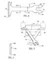
- FIG. 1is an anterior view of a right knee of a human anatomy
- FIG. 2is a plan view of a narrow saw blade according to one embodiment
- FIG. 3is a perspective view of the saw blade in conjunction with a guide or cutting block
- FIG. 4is a cross-sectional view of the saw blade taken along line 4 - 4 ;
- FIG. 5is an elevational view of a portion of a tibia and an angled saw blade according to a second embodiment
- FIG. 6is a plan view of an offset saw blade according to an embodiment
- FIG. 7Ais a perspective view of a cutting block assembly with a saw blade disposed therethrough;
- FIG. 7Bis a cross-section taken along the line B-B of FIG. 7A ;
- FIG. 8is a cross-sectional view of a rail assembly according to an alternative embodiment
- FIG. 9is a perspective view of a cutting block and rail assembly according to an alternative embodiment
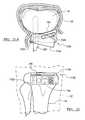
- FIG. 10Ais a side elevational view of a femur including the cutting block assembly, according to an embodiment, attached thereto;
- FIG. 10Bis a perspective view of a knee joint illustrating an exemplary use of the cutting block and saw blade
- FIG. 10Cis a cross-sectional view of the cutting block assembly affixed to a distal end of a femur;
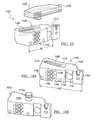
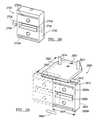
- FIG. 11is a perspective view of a moveable guide block
- FIG. 12is a perspective view of a movable guide block assembly
- FIG. 13is a partial cross-sectional view at a knee including a movable guide assembly
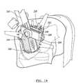
- FIG. 14is a perspective environmental view of a movable cut guide in use
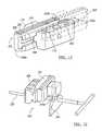
- FIG. 15is an isometric view of a tibial resection apparatus according to the present teachings.
- FIG. 16Ais an isometric view of an exemplary support block for the tibial resection apparatus of FIG. 15 ;
- FIG. 16Bis an isometric view of an exemplary support block for a tibial resection apparatus according to the present teachings
- FIG. 17Ais a top view of an exemplary cutting guide for the tibial resection apparatus of FIG. 15 ;
- FIG. 17Bis a top view of an exemplary cutting guide for coupling to the support block FIG. 16B ;
- FIG. 18is a front view of the cutting guide of FIG. 17A ;
- FIG. 19is a side view of the cutting guide of FIG. 17A ;
- FIG. 20is an isometric view of a support block of FIG. 15 , shown a stylus;
- FIG. 21Ais an environmental plan view of a libial resection apparatus according to the present teachings in a first position on a right leg;
- FIG. 21Bis an environmental plan view of a tibial resection guide according to the present teachings in a second position on a right leg;
- FIG. 22is an environmental side view of a tibial resection apparatus of FIG. 21 on a right leg;
- FIG. 23is an environmental isometric view of a support block and tibial guide attached to the tibia according to the present teachings.
- FIG. 24is an isometric view of a support block attached to an alignment handle according to the present teachings.
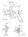
- FIG. 25Ais a plan view of a rotating guide according to various embodiments.
- FIG. 25Bis a perspective view of the guide of FIG. 25A ;
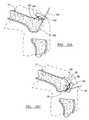
- FIG. 26is an exploded perspective view of a moveable resection guide according to various embodiments.
- FIG. 27is a detail environmental view of the moveable resection guide of FIG. 26 ;
- FIG. 28is a perspective view of a moveable resection guide according to various embodiments.
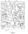
- FIG. 29is a perspective view of a kit including various saw blades and cutting block assemblies
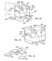
- FIG. 30is a perspective view of a modular sizing device according to the present teachings.
- FIG. 31is a perspective view of the sizing device of FIG. 30 , shown without a stylus;
- FIG. 31Ais a perspective view of a modular sizing device according to the present teachings.
- FIG. 32is an environmental perspective view of a modular cutting device according to the present teachings.
- FIG. 33is a perspective view of the cutting device of FIG. 32 , shown without an alignment guide;
- FIG. 34is a perspective view of an alignment guide for the cutting device of FIG. 32 ;
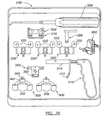
- FIG. 35illustrates a kit of surgical components according to the present teachings
- FIG. 36is an environmental view of the sizing device of FIG. 30 , shown during a surgical procedure;
- FIG. 37is a perspective view of soft tissue retractor according to the present teachings shown coupled with a cutting guide;
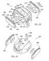
- FIG. 38is a front plan view of a guide apparatus
- FIG. 39is a front exploded perspective view of a guide apparatus according to various embodiments.
- FIG. 40is a back perspective exploded view of a guide apparatus according to various embodiments.
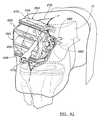
- FIG. 41is an environmental view of a guide apparatus in use.
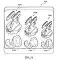
- FIG. 42is a plan illustration of a kit including a guide apparatus according to various embodiments.
- a knee joint 10(illustrated as a right leg) of a human anatomy includes a femur 12 that can articulate with a tibia 14 .
- the tibia 14 of the right legincludes a medial side 14 a and a lateral side 14 b .
- a meniscus 16Disposed between the femur 12 and the tibia 14 is a meniscus 16 , which cushions the articulation and provides a bearing between the two boney portions or structures.
- the knee joint 10further includes a fibula 18 and a patella 20 .
- a soft tissue 22Surrounding the knee joint 10 is a soft tissue 22 , which includes muscle, adipose tissue, and the epidermis.
- the femur 12includes a first condyle 26 and a second condyle 28 .
- first condyle 26may be a lateral condyle when the knee is a right knee, such as the knee illustrated in FIG. 1 .
- first condyle 26may be a lateral condyle when the knee is a right knee, such as the knee illustrated in FIG. 1 . It will be understood that the following discussion and instruments may also applicable, with minor changes, if any, to a left knee as well.
- the knee joint 10may become damaged or injured such that small fractures 24 or other injuries or deteriorations occur. When such injuries become great enough, the knee joint 10 may be resected and a prosthetic implanted to replace the articulating portions.
- the first and second condyles 26 , 28define an inferior surface of the femur 12 .
- the femur 12is generally rounded and includes arcs and rounded surfaces of the first and second condyles 26 , 28 on the inferior side of the femur 12 .
- These convex surfacesprovide for easy articulation of the femur 12 with the tibia 14 .
- convex surfacesare defined by the femur 12 on the anterior 12 b and posterior 12 c (shown in FIG.
- an incision 30is made through the soft tissue 22 to gain access to the knee joint 10 (in FIG. 10B ).
- various styles and methods of making the incision 30are known, however a surgeon may find it desirable to provide a less invasive incision 30 . Therefore, the incision 30 is generally between about 1 cm and about 10 cm in length to provide access to the knee.
- the incision 30is made through the soft tissue 22 , the incision 30 may be a small size and moved relative to the femur 12 and the tibia 14 to perform the procedure. Nevertheless, the smaller incision 30 , the less trauma provided to the soft tissue 22 . Because of the small incision 30 , the instruments provided to resect the knee joint 10 are designed to efficiently perform their tasks without further traumatizing the soft tissue 22 and able to fit through the incision 30 .
- a saw blade 100 for resecting a portion of the knee joint 10is illustrated.
- the saw blade 100may be used to resect the inferior portion of the femur 12 , including the first and second condyles 26 , 28 or the superior portion of the tibia 14 .
- the saw blade 100includes a tool engaging end or section 102 , a body or neck 104 , and a cutting head 106 .
- the tool engaging end 102includes a tool receiving notch 108 , which is defined by a first leg 110 and a second leg 112 . In this way, a portion of a power tool (not illustrated, but generally known) can be received within the tool receiving notch 108 to operate the saw 100 within the knee joint 10 .
- any appropriate means or designmay be used to affix the saw blade 100 to any appropriate tool.
- the tool engaging notch 108is simply exemplary of any numerous method, which may be used to properly affix the saw blade 100 to a power tool.
- Other exemplary methodsinclude a compression fit with a set screw or a bore formed in the saw blade 100 , which would receive a set screw, but not include a notch. Therefore, the illustration of the exemplary tool engaging notch 108 is not intended to limit the present disclosure or the following claims.
- the tool engaging end 102may be any appropriate size, including any appropriate width or depth to be properly received within a power tool.
- the power toolmay require that the tool engaging end 102 of the saw blade 100 be at least 1.5 cm in width. Therefore, the tool engaging end 102 may be at least 1.5 cm in width.
- the neck 104 of the saw blade 100has a width A which is selected to be narrower than a width B of the cutting head 106 .
- width A of the saw blade 100can be any appropriate width, it is generally selected to be relatively small to lessen abrasion and trauma to the soft tissue 22 defining the incision 30 . This design also increases utility of a cutting guide as described more fully herein.
- the width A of the neck 104also allows a greater area to be resected by the saw blade 100 . Specifically, as illustrated in FIG. 3 , the narrow width A of the neck 104 allows the cutting head 106 to resect an area which is beyond the width of a cutting block 120 . Because of the narrow width A of the neck 104 , the cutting head 106 is able to easily resect an area at least a distance X beyond the edge of the slot 121 defined by the cutting block 120 . The slot 121 defines a guide area of the cutting block 120 .
- a saw blade including a neck and cutting head of equal widthslimits the amount of area that a user is able to resect outside of the width of the slot 121 .
- the narrow neck 104allows the distance X to be resected outside of the width of the slot 121 .
- the saw blade 100is able to resect the distance X on both sides of the cutting block 120 during use.
- the cutting head 106may have a different selected width B.
- the cutting teeth 114move in conjunction with the cutting head 106 and provide a sawing action to saw and remove material that is to be resected.
- the cutting teeth 114may be any appropriate design or shape to provide the desired resection, speed or efficiency.
- the width B of the cutting head 106may be selected to allow for a greater cutting width than the width of the neck A.
- the width A of the neck 104may be selected to be smaller than the width of the retracted incision 30
- the width B of the cutting head 106may be selected to be greater than the width of the incision 30 .
- the width B of the cutting head 106may be at least twice as big of the width A of the neck 104 . This provides a cutting area, which is greater than the width of the neck 104 , while minimizing trauma to the soft tissue 22 .
- the neck 104 of the saw blade 100includes a first side 104 a and a second side 104 b .
- the edges or sides 104 a and 104 b of the neck 104may include convex or other smooth non-angular shapes.
- the smooth and non-angular shapesfurther minimize trauma to the soft tissue 22 during operation. Simply, the saw 100 vibrates back and forth to move the cutting teeth 114 . Even though the width A of the neck 104 is less than the width of the retracted incision 30 , the edges 104 a and 104 b of the neck 104 may still contact the soft tissue 22 . Therefore, removing the harsh or angular edges of the neck 104 help minimize trauma, to the soft tissue 22 .
- an angled saw blade 130including a tool engaging end 132 , a neck 134 , and cutting head 136 is illustrated.
- the saw blade 130may be used in conjunction with a cutting block (illustrated herein), which is mounted relative the tibia 14 for the procedure. An incision is made in the soft tissue 22 to allow access of the saw 130 to the tibia 14 .
- the tool engaging end 132may include a power tool engaging notch 140 , such that a power tool may operate the saw blade 130 .
- the cutting head 136defines a plurality of cutting teeth 142 .
- the neck 134 of the saw blade 130may have a width, which is less than the width of the cutting head 136 .
- the width of the neck 134may be less than the width of the incision 30 made in the soft tissue 22 .
- the tool engaging end 132defines a first longitudinal axis D.
- the neck 134defines a second longitudinal axis E.
- the first longitudinal axis D of the tool engaging body 132is angled relative to the second longitudinal axis E of the neck 134 .
- the angle F between the two axesmay be any appropriate angle.
- the angle Fmay be an obtuse angle to provide access to both sides of the tibia 14 .
- the angle Fallows an incision 30 to be placed on a selected side of the tibia 14 through the soft tissue 22 .
- the incisionmay be formed medially relative to the tibia 14 (as in FIG. 1 ).
- the saw blade 100would need to be moved relative to the tibia 14 to reach the lateral side 14 a . This may cause trauma to the soft tissue 22 by moving the saw blade 100 or a cutting block. Especially if a cutting block were fixed relative the tibia 14 , it would be very difficult and require additional time to move a cutting block relative the tibia 14 . With the use of the angled saw blade 130 , the lateral side 14 a of the tibia 14 can be easily reached with the cutting teeth 142 .
- the angle Fallows the cutting head 136 to be positioned in a space not aligned with the first longitudinal axis C of the tool engaging end 132 . This allows the cutting teeth 142 to cut an area of the tibia 14 , which is not aligned with the axis D. It will be understood that the angled saw blade 130 may also be angled in the opposite direction. This will allow for the angled saw blade 130 to enter the knee area on the lateral side and reach to the medial side of the tibia 14 . Regardless of the size of the angle F or the direction of the angle F, the angled saw blade 130 allows the cutting teeth 142 to cut an area that is not aligned with the longitudinal axis of the tool engaging body 132 .
- the offset saw blade 150includes a tool engaging section 151 , a cutting head 152 , and a neck portion 153 .
- the neck portion 153includes a first angle or bend 154 and a second angle or bend 155 . This allows the cutting head 152 to be laterally offset from the tool engaging section 151 without being angled thereto. More specifically, the tool engaging section 151 extends along a first or tool engaging section axis G while the cutting head 152 extends along a second or cutting head longitudinal axis H. The first axis G is laterally offset from the second axis H, but is parallel thereto. Therefore, the offset saw blade 150 can resect a portion of anatomy not in line with the cutting section 151 yet parallel therewith.
- the angled sections 154 and 155may also be referred to or illustrated as “steps” of the neck portion 153 .
- the translating cutting block system 160includes a cutting block 162 , which is able to translate or slide on a rail or track member 164 .
- the cutting block 162includes a post or wall 166 a and 166 b , which is adapted to push the soft tissue 22 away from a saw blade bore 168 during use, as described further herein.
- Formed through the cutting block 162is the saw blade bore 168 .
- the cutting block 162is illustrated to define a saw blade bore or slot 168 , which acts as a saw blade guide, as described further herein, a saw blade bore 168 is not required for a cutting block 162 .
- the cutting block 162may also only define surfaces which are used as cutting guides. Therefore, rather than placing the saw blade 100 through a slot formed in the cutting block 162 , the saw blade 100 would only ride or translate along a surface of the cutting block 162 to direct the saw blade during use. Therefore, it will be understood that a saw blade bore 168 may define a guiding section or a surface of the cutting block 162 alone may define a guiding section.
- Cutting blocks for resectionsimilar to the cutting block 162 are generally known, such as the 4-IN-1 CUTTING BLOCK, supplied by Biomet, Inc. of Warsaw, Ind.
- the cutting block 162guides the saw blade 100 or 132 during a resection procedure to ensure that the proper areas of the boney portions are cut during the resection.
- the cutting block 162is able to translate medially/laterally, by riding on the rail 164 .
- the cutting block 162includes a rail engaging section 170 , which may define a female dove tail.
- the rail 164includes a rail translation section 172 , such as a complimentary male dove tail.
- the rail engaging section 170operably engages the rail translation section 172 so that the cutting block 162 is not able to substantially distract from the rail 164 . Nevertheless, the cutting block 162 is able to move medial/laterally in the direction of arrow G by moving along the rail 164 .
- the rail translation section 172may define any portion complimentary to the guide or cutting block translation portion 170 to allow the cutting block 162 to translate relative the rail 164 .
- the rail translation section 172may define a “T” shaped projection or a recess. Therefore, the guide translation portion 170 would be complimentarily shaped to engage the rail translation portion 172 for translation of the cutting block 162 .
- the cutting block 162may be translated along the rail 164 , the cutting block 162 may also be selectively locked relative the rail 164 , if desired.
- the cutting block 162may include a locking pin 174 , which can be depressed to engage notches 176 formed in the rail 164 .
- the locking pin 174may be engaged or unengaged in any position, which can be selected by a user by depressing the locking pin 174 . This allows the cutting block 162 to be moved to a selected position relative the rail 164 and locked in place while the saw blade 100 is used. It will be understood that alternative means of locking the cutting block 162 in a selected position can also be used.
- a set screwcan be set against any position on the rail 164 to lock the cutting block 162 in a selected position. This allows for a substantially infinite selection by a user. Alternatively, no locking portion may be provided, such that the cutting block 162 is always free to move, depending upon the selections of the user.
- the rail member 164 ′similarly includes the bone anchor portion 180 .
- the rail member 164 ′includes a track translation receiving area 182 .
- the rail member 164 ′may also include an engaging section 184 .
- the track translation section 172 ′defines a complimentary engaging section 186 to engage the rail member 164 ′.
- a pin 188may extend from the track translation section 172 ′ to engage the track translation receiving portion 184 .
- the rail member 164 ′engages a separate track translation section 172 ′. Therefore, a plurality of track translation sections 172 ′ may be provided with the track member 164 ′ and a selection may be made by a user.
- the rail 190includes a rail translation section 192 which is shorter than the length of the cutting block 162 .
- the cutting block 162defines a cutting block translation section 194 which is longer than the rail translation section 192 .
- movement of the cutting block 192is allowed because the block translation section 194 is longer than the rail translation section 192 .
- the rail 190need not be longer than the cutting block 162 to allow the cutting block 162 to translate relative the rail 190 .
- the rail 164is mounted to a selected area of the boney portion, such as a distal side 12 a of the femur 12 or a portion of the tibia 14 using at least one of a plurality of mounting posts 180 .
- the mounting posts 180are fit into predrilled holes or bores formed into the femur 12 .
- the rail 164is mounted directly to the femur 12 . Therefore, the cutting block assembly 160 is mounted to a boney structure inside the soft tissue 22 . Screws may also be used to tighten the posts 180 in place by providing a bore through the post 180 . Alternatively, semi-permanent cements or adhesives may be used to fix the posts 180 in place.
- the interaction of the track translation section 172 and the guide translation portion 170may be substituted with any other proper engagement.
- the rail 164may define a male “T” cross-section, which is engaged by a female “T” cross-section formed on the cutting block 162 .
- Any appropriate engagement between the rail 164 and the cutting block 162may be provided, as long as the cutting block 162 is able to translate relative the rail 164 , yet not substantially distract from the rail 164 during or after the translation. It will be understood, however, that the cutting block 162 may distract from the rail 164 if selected.
- the cutting block 162may translate relative the rail 164 by distracting the cutting block 162 from the rail 164 and moving the cutting block 162 relative thereto.
- the cutting block 162is not locked relative the rail 164 , it may be selected that the cutting block 162 distracts from the rail 164 to allow for greater freedom of movement of a user of the cutting block 162 .
- the incision 30is made near the knee 10 to allow access to the knee 10 by the various instruments. Once the incision 30 is made, the distal or inferior end 12 a of the femur 12 is first resected to form a substantially flat and planar region.
- the cutting block assembly 160is fixed to an anterior side 12 b of the femur 12 .
- the saw blade 100is then guided with the cutting block 162 through the incision 30 to form the distal cut on the distal end 12 a of the femur 12 .
- the interaction of the cutting block 162 and the rail 164allows the cutting block 162 to be translated medial laterally relative to the femur 12 .
- the cutting block 162can be minimized in size.
- the cutting block 162need not be the width of the femur 12 required to be resected because the cutting block 162 is able to move medial laterally relative the femur 12 .
- This resectionsubstantially removes the condyles 26 and 28 and forms a substantially flat area to form the first resection portion of the knee 10 resection.
- the cutting block assembly 160can be mounted thereto.
- the rail 164is mounted to the femur 12 using the mounting posts 180 . This allows the rail 164 to be substantially fixed relative the femur 12 for use of the cutting block 162 .
- the cutting assembly 160is inserted through the incision 30 and mounted to the distal end 12 a of the femur 12 . This allows the cutting block 162 to translate medially/laterally while mounted on the rail 164 , which is mounted or fixed to the femur 12 .
- the cutting block 162allows for resection of the anterior side 12 b and posterior side 12 c of the femur 12 .
- the saw blade 100can be inserted through the cutting block 162 to resect the posterior side 12 c of the femur 12 . Therefore, the exemplary illustration resecting the anterior side 12 b of the femur 12 is not meant to limit the following claims.
- the saw 100can be inserted through the incision 30 and through the cutting block 162 . This allows the saw 100 to be properly aligned relative to the femur 12 using the cutting block 162 . Therefore, the saw blade 100 can resect portions of the anterior side 12 b of the femur 12 . Due to the narrowness of the neck 104 of the saw blade 100 , the incision 30 may be small, even though the saw blade 100 must move from side to side to resect portions of the femur 12 .
- the saw blade 100 illustrated in solid linesshows the position of the saw blade before it moves to resect a portion of the femur 12 .
- the saw blade 100 ′shown in phantom lines, illustrates a portion of the vibrational motion of the saw blade 100 while in operation.
- the narrow neck 104does not substantially engage the edges of the incision 30 during this process. Therefore, the trauma to the soft tissue 22 is minimized due to the narrow neck 104 .
- the cutting block 162 and cutting assembly 160 as a wholeis minimized in size to reduce trauma to the soft tissue 22 during the positioning and removal of the cutting assembly 160 .
- the cutting block 162can be translated along the rail 164 to a second position. In this second position, the cutting block 162 may be held or locked in place with the locking pin 174 . Alternatively, no locking mechanism may be used to allow the cutting block 162 to move freely depending upon the desires of the user. Nevertheless, the cutting block 162 may translate to the medial side of the knee 10 , as the knee 10 illustrated in FIG. 6 is a right knee, such that the saw blade 100 -is-able to easily-resect the medial side of the femur 12 .
- the saw blade 100may be positioned to cut the anterior side 12 b of the femur on the medial side of the femur 12 .
- the rail 164needs only be mounted once while the cutting block 162 can be translated along the rail 164 to cut all the necessary portions of the anterior side 12 b of the femur 12 .
- the cutting block 162may be removed and rotated to cut the posterior side 12 c of the femur 12 with the saw blade 100 .
- An appropriately configured cutting block 162allows the saw blade 100 to resect both the anterior 12 b and the posterior 12 c of the femur 12 without rotating the cutting block 162 .
- the soft tissue holders or pushers 166 a and 166 bExtending from the cutting block 162 are the soft tissue holders or pushers 166 a and 166 b .
- the soft tissue pushers 166 a and 166 bare positioned to ensure that the soft tissue 22 does not intersect the guide bore 168 of the cutting block 162 .
- the soft tissue pushers 166 a and 166 bhelp move the incision 30 relative the femur 12 during the procedure.
- the incision 30is a substantially small incision, such that the instruments may be inserted into the knee 10 , but not so large as to produce large amounts of trauma to the soft tissue 22 .
- the movement of the cutting block 162can move the incision 30 and the surrounding soft tissue 22 relative the femur 12 to allow for the cutting block 162 to easily move along the rail 164 .
- the cutting block 162helps reduce trauma to the soft tissue 22 surrounding the knee 10 .
- any appropriate saw blademay be used in conjunction with the cutting block 162 , therefore the cutting assembly 160 , it is not necessarily exclusive to use with the narrow saw blade 100 .
- the femur 12is illustrated resected such that the anterior side 12 b has been resected to form a substantially flat and planar portion.
- the posterior side 12 c of the femur 12has also been resected.
- the saw blade 100has been inserted through the cutting block 162 to resect the posterior side 12 c of the femur 12 .
- the rail 164need only be mounted once to resect both the anterior side 12 b and the posterior side 12 c of the femur 12 .
- the use of the translating cutting block 162allows the rail 164 to be positioned only once to resect both the medial and lateral portions of the femur 12 as well.
- a guiding memberfor example, a translating or sliding cutting block
- the translating cutting block 162may translate relative to the rail 164 to form a resection of a portion of a bone or other selected anatomical portion.
- the cutting block 162may assist in guiding a cutting tool even if the cutting block is not the same size or dimension, in at least one direction, as the resection to be made. Nevertheless, various cutting blocks may be used in various methods to form resections of various portions of the anatomy.
- a guide member 200such as a translating or sliding cutting block
- the translating cutting block 200may be used to form any appropriate portion, such as a resection in a selected portion of the anatomy.
- the cutting block 200may be used in forming a distal resection of a the femur 12 .
- the cutting block 200may be used with any appropriate portions to assist in or guide the cutting block 200 for various preparations.
- the cutting block 200may generally include a first attachment and/or rail portion 202 .
- the translating cutting block 200may also include a guide or translating portion 204 .
- the guide portion 204may include a slot or cutting guide 206 that may define a cutting guide surface 208 .
- the guide surface 208may be any portion defined by the cutting or translating member 204 to assist in guiding a selected instrument, such as the saw blade 100 , to form a selected resection.
- the translating guide portion 204may be used to guide any appropriate member or instrument relative to a selected portion of the anatomy to perform a selected procedure.
- the translating or guide member 204may also include a second guide slot 210 or any appropriate number of guide slots for various purposes or applications.
- the translating cutting block 200includes the translating member 204 that can translate relative to the fixed or rail member 202 .
- the guiding block portion 204may move from a first position to a second position 204 ′, illustrated in phantom.
- the translating cutting block 200may be positioned relative to a selected portion of the anatomy to cut a first portion of the anatomy or guide a selected instrument relative to a portion of the anatomy, and move to a second position to cut a second portion of anatomy or guide an instrument relative to a second portion of the anatomy.
- the translating block 200may include a size, such as that discussed above, that is smaller than a selected working area.
- the cutting block 200may be less than about 8 cm, and may include an exemplary length of about 4 cm.
- various instrumentsmay be used for minimally, less invasive, or conventional open procedures. The reduced size and characteristics of various instruments may reduce the recovery time experienced by a patient after a procedure. Also the time for the procedure may be reduced as well as many other effects.
- the rail member 202may define a tenon 202 b of a rail portion.
- the rail member 202may also define any other projection, such as a “T” or “D” shape or any appropriately shaped depression.
- the guide member 204may define a complimentary portion, such as a mortise 204 c , to associate with the tenon 202 b .
- the guide member 204may include or define any other depression or projection to associate with the rail member 202 .
- various portionsmay be provided to lock or fix the guide member 204 relative to the rail member 202 .
- the guide member 204may move generally freely relative to the rail member 202 in a selected manner.
- the rail member 202may include a bore or a plurality of bores 212 to receive a selected member, such as a pin or screw to fix the translating mechanism 200 relative to a portion of the anatomy. It will be understood, however, that any appropriate mechanism may be provided to assist in positioning the rail or fixed member 202 relative to a selected portion of the anatomy.
- a pin or member 236FIG. 14 may extend from a surface of the fixed member 202 to assist in holding the rail member 202 relative to a selected portion of the anatomy.
- the rail member 202may include a plurality of mechanisms to substantially assist in positioning or selectively positioning the rail member 202 in a selected position.
- a plurality of the bores 212may be provided, each including a different orientation relative to the rail member 202 . Therefore, various mechanisms, such as pins or screws, may be positioned through a selected plurality of the bores to position the rail member 202 in a selected position that may be different depending upon the selection of bores 212 .
- Positioning the rail member 202 in a different positionmay allow for movement of the guiding block 204 to various orientations relative to the anatomy. Therefore, it will be understood that the cutting block 200 may be positioned relative to the anatomy in any appropriate way to assist in guiding a selected mechanism or tool relative to the anatomy.
- the translating guiding block 200may include a central or positioning bore 214 .
- the positioning bore 214may be provided through any appropriate portion of the translating cutting block 200 to assist in associating the translating cutting block 200 or the selected instrument.
- an intramedullary rod or positioning memberas discussed herein, may be positioned relative to the anatomy and a portion of the rod may be engaged or associated with the central bore 214 to position the cutting block 200 relative to the rod and the anatomy.
- the translating cutting block 200may be positioned relative to an intramedullary (IM) rod 220 for use of the translating cutting block 200 , or at least positioning of the translating cutting block 200 .
- the IM rod 220may be positioned relative to a paddle or instrument 224 operable to be positioned in the femur 12 . It will be understood that the cutting block 200 may be positioned in any appropriate manner and using the IM rod 220 is merely exemplary.
- the paddle instrument 224may be interconnected with the IM rod 220 and positioned relative to, such as inserted into, a portion of a bone, such as the intramedullary canal of the femur 12 .
- the paddle instrument 224may be selected from one or more paddle instruments based upon a paddle portion 226 .
- the paddle portion 226may be selected for various purposes, such as selecting a distance from a distal portion 228 of the femur 12 .
- the paddle portion 226may also be selected for various other purposes, such as selecting a varus and/or valgus angle for formation of the distal cut of the femur. Therefore, it will be understood that the paddle portion 226 or the instrument 224 may be selected for various appropriate purposes. For example, a plurality of the instruments 224 may each include different paddle portions 226 . The different paddle portions may provide different attributes, such as a selected varus and or valgus angle. The angle may be translated in positioning the cutting block 200 with the instrument 224 , as discussed herein.
- an attachment mechanism 234may be positioned relative to the femur 12 and the paddle instrument 224 .
- the connection mechanism 234may be provided to interconnect, at least temporarily, the translating cutting block 200 with the instrument 224 for selectively positioning the translating cutting block 200 relative to the femur 12 .
- the connection portion 234may not be necessary and may be provided to allow for a selected interconnection.
- the translating cutting block 200may be positioned with the paddle instrument 224 without use of the connection instrument 234 .
- the translating cutting block 220may associate or be interconnected with the paddle instrument 224 without an internal or separate connection means. Nevertheless, it will be understood that the connection instruments 234 may be used for various purposes.
- the interconnection mechanismincludes a pin 234 a that can interconnect with the paddle portion 226 of the instrument 224 .
- the pin 234 aallows an interconnection between the guide block 200 and the paddle portion 226 . As discussed above this may assist in forming the appropriate angles in the resection. Also, the pins 234 a allow for selectively removing the various portions to assist in the resection or for other purposes.
- the translating cutting block 200may then be interconnected with the interconnection portion 234 .
- the connection member central bore 214extending from the translating or guide portion 204 of the translating cutting block 200 , may interconnect with the interconnection mechanism 234 .
- the interconnection of the translating portion 204 with the interconnection mechanism 234may allow for selective positioning of the guide surfaces 208 relative to the femur 12 in a selected manner.
- the interconnectionmay be any appropriate connection.
- a magnet or magnetsmay be provided to interconnect the translating cutting block 200 for positioning thereof.
- one or more of the guide surfaces 208may be provided and defined by the guide member 204 for guiding a selected instrument, such as a saw blade. Therefore, positioning the guide member 204 with the interconnection mechanism 234 may assist in selectively positioning the guide surfaces 208 relative to the femur 12 in a selected manner.
- the rail portion 202may be interconnected with the femur 12 near the distal end 228 in a selected manner.
- a pin or screw 236may be provided to interconnect the rail portion 202 with the femur 12 .
- the pin 236may be any appropriate pin, and for example, may include a quick release pin, such as a Quick-Release Drill BitTM, provided by Biomet, Inc. of Warsaw, Ind.
- a quick release pinsuch as a Quick-Release Drill BitTM, provided by Biomet, Inc. of Warsaw, Ind.
- the quick release pinsmay allow for an easy and efficient connection of the rail portion 202 with the femur 12 and for an efficient and effective removal therefrom.
- the rail member 202may be connected to the femur in any appropriate location. Nevertheless, it may be selected to position the bores of the rail member 202 away from the distal end 228 of the femur 12 .
- the bores 212may also, or alternatively, be positioned near the distal end 228 of the femur 12 . Also the distance the bores 212 are positioned from the guide member 204 may be selected for various purposes.
- the paddle instrument 224 and the IM rod 220may be removed from the femur 12 .
- the removal of the paddle portion 224 , the interconnection portion 234 , and the IM rod 220may allow for a clear or easier access to the distal portion 228 of the femur 12 .
- a selected instrumentmay be guided with the translating guide portion 204 .
- the translating guide portion 204may guide a selected instrument, such as a saw 240 .
- the saw 240may be any appropriate saw, such as a reciprocating saw powered by a hand tool 242 or the saw 100 .
- the saw 240may pass through the guide slot 206 and be guided along the guide surface 208 .
- the guide portion 204may be provided to guide the saw 240 relative to the femur 12 . This may allow for a resection of the distal portion 228 of the femur 12 to form a substantially planar or resected surface 244 of the femur 12 .
- the resected surface 244 of the femur 12may be any selected size.
- the resected portion 244 of the femur 12may be substantially a width or distance between the epicondyles of the femur 12 .
- the distance between the epicondylesmay be dependent upon the size of the patient, but may generally be about 4 cm to about 13 cm (about 1.5 inches to about 5 inches).
- the guide member 204may include a length between the first end 204 a and the second end 204 b that is less than the distance of a selected femur. Therefore, as discussed above, the guide member 204 may move relative to the rail or fixed portion 202 .
- the guide member 204may be moved relative to the rail portion 202 to complete a resection of the femur 12 in a selected manner.
- the guide member 204need not include a length, for example a length of the guide surface 208 , an entire dimension or size of the surface to be resected.
- the guide member 204is able to move, such as translate or rotate, relative to the rail member 202 .
- the guide member 204may allow movement of the guide surface 208 .
- the resectionmay be completed using the guide member 204 and generally not requiring the resected surface, or a part thereof, to guide the tool to form the resection.
- the guide member 204may provide the guide surface for the entire resection to be performed.
- the rail portion 202may be moved due to the plurality of the bores 212 in the rail member 202 . Therefore, for example, if the movement or translation of the guide member 204 is not great enough to complete a resection of the femur 12 at a selected manner, the rail portion 202 may be moved relative to the pins 236 . This may allow for further resection to form the resected surface 244 .
- the bores 212may also allow for additional resection to be performed for various reasons.
- the pins 236may be positioned in various bores to select an amount of resection to occur.
- the guide member 204need not be an extended or large size, due at least in part to a movement of the guide member 204 relative to a portion of the anatomy, such as the femur 12 .
- the guide member 204may be used to guide the entire formation of the resected surface 244 due, at least in part, to the movement of the guide member 204 .
- the resected surface 244 or a portion thereofneed not be used to guide the saw 240 relative to another portion of the anatomy, such as to complete the resected surface 244 , due at least in part to a movement or a translation of the guide member 204 .
- the rail portionincluding a depth or dimension 202 a may allow for positioning of the rail member 202 relative to a selected portion of the femur 12 .
- the translating block 200may be positioned substantially near the distal portion 228 of the femur 12 , such as substantially near the condyles. Therefore, the incision formed in the soft tissue relative to the femur 12 may be substantially small or minimized and still allow passing and positioning of the translating block 200 .
- the bores 212 defined in the rail portion 202allow for fixing the translating member 200 relative to the anatomy, such as the femur 12 , near the distal portion 228 of the femur 12 for various purposes, such as reducing the size of the incision.
- various other portions of the anatomymay be resected or prepared, such as a proximal portion of a tibia.
- various other resections of the femur 12may be formed.
- Various guide memberssuch as translating movable guide members may be used to form various resections of the femur, such as an anterior and posterior cut, and an anterior and posterior chamfered cut.
- the various resections of the femur 12may allow for positioning of a distal femoral implant on the femur 12 through the incision.
- the distal femoral implantmay articulate with the tibia or articulate with a tibial implant according to various embodiments. Nevertheless, it will be understood that various resections may be formed to allow for replacement or repair of selected anatomical portions.
- an exemplary tibial resection apparatus 1100includes a support block 1102 and a cutting guide 1104 .
- the support block 1102may have a superior surface 1106 ( FIG. 16A ) that defines a groove 1108 .
- the groove 1108may be oriented medially-laterally and can be curved generally parallel to a curved attachment surface 1110 of the support block 1102 .
- the support block 1102 of FIG. 16Ais. configured for a left leg. It will be understood, as illustrated in FIGS. 21A-22 , that a support block 1102 may also be configured for the right leg.
- the curved attachment surface 1110is configured to mate with at least a portion of the medial surface 14 a of a proximal portion of the tibia 14 , as illustrated in FIGS. 21A and 22 .
- the support block 102can include a cut-out 1130 and an aperture 1132 that can receive a fastener or holding portion 1136 for attaching an extramedullary rod 1134 of a standard tibial guide 1139 .
- the standard tibial guide 1139can be attached to the distal tibia with a yoke or other known attachment device 1162 .
- a set of holes 1138including a plurality of pairs of holes 1138 , can be arranged in parallel and equidistant pairs, or any appropriate format, on a front surface 1150 of the support block 1102 .
- the holes 1138are configured to selectively receive respective locking pins of a tibial stylus 1200 for setting the depth of resection.
- a tip 1202 of the stylus 1200is at the level of the saw guide slot 1112 of the cutting guide 1104 .
- Engaging the stylus 1200 with the next pair of holes 1138corresponds to an increase of the distance of the tip 1202 by a predetermined amount equal to the spacing between the consecutive pairs of holes 1138 , such as, for example, about 2 mm.
- Engraved lines or other indicator markings 1152can be provided along each pair of holes 1138 to indicate the level of the tip 1202 at each location of the stylus 1200 , thereby functioning as a stylus scale.
- the support block 1102can also include an engagement area 1154 that can include a slot or opening for receiving a handle 1160 with openings 1164 for supporting other alignment rods, as illustrated in FIG. 24 .
- the cutting guide 1104may define a saw blade slot 1112 and includes a peg 1114 extending from an inferior surface 1105 of the cutting guide 1104 .
- the peg 1114is configured to be received in the groove 1108 , such that the cutting guide 1104 can slide along the groove 1108 relative to the support block 1102 .
- the groove 1108 and the peg 1114can include complementary engagement or locking features, such as, for example, a rim 1116 projecting from the wall of the groove 1108 into the groove 1108 and a slot 1118 defined by upper and lower shoulders 1120 of the peg 1114 .
- the cutting guide 1104can stably rotate about the peg 1114 relative to the support block 1102 .
- the cutting guide 1104can have a straight edge, one angled edge, or two angled edges 1122 on the side facing the tibia 14 .
- the edges 1122assist in moving and help provide clearance for movement of the cutting guide 1104 during movement of the cutting guide relative to eh support block 1102 ( FIGS. 21A and 21 B).
- the saw blade slot 1112has a width W ( FIG. 15 ) that is generally greater than a corresponding width of the saw blade 240 , or other appropriate saw or cutting tool, to allow a swinging motion of the saw blade relative to the saw blade slot 1112 , in addition to the motion of the saw blade that is provided by the sliding motion of the cutting guide 1104 along the groove 1108 .
- Cuttingcan begin at the medial surface 14 a of the tibia 14 and proceed posteriorly and laterally, advantageously facilitated by the sliding motion of the cutting guide 1104 . It will be understood that the resection can begin at any appropriate location and proceed according to various methods.
- the tibial resection apparatus 1100 of FIG. 15is merely exemplary. Arcuate sliding is allowed between the support block 1102 and the cutting guide 1104 by including a groove-peg engagement device.
- the groove 1108is defined in the superior surface of the support block 1102 and the peg 1114 extends from the inferior surface 1105 of the cutting guide 1104 . It will be understood that other sliding engagement devices are contemplated.
- the groove 1108can be defined in the inferior surface 1105 of the cutting guide 1104 , and a peg 1114 a can extend from the superior surface 1106 of the support block 1102 , as illustrated in FIGS. 16B and 17B .
- the groove and peg arrangementis generally configured to enable relative sliding between the support block 1102 and the cutting guide 102 along an angled and/or arcuate path defined by the groove 1108 , whether the groove 108 is defined on the support block 1102 or the cutting guide 1104 .
- the peg 1114can be modularly coupled to the support block 1102 or the cutting guide 1104 .
- the peg 1114can also be a bolt, a pin or ball configured for engagement with the groove 1108 .
- the engagement of the peg 1114 and the groove 1108may also allow for rotation of the cutting block 1104 relative to the support block 1102 .
- the cutting guide 1104may move in any appropriate manner relative to the tibia 14 and the support block 1102 .
- the support block 1102may be positioned relative to the tibia 14 using any appropriate mechanism, such as the support rod or extramedullary rod 1139 or the handle 1160 (see FIG. 24 ).
- any appropriate mechanismsuch as the support rod or extramedullary rod 1139 or the handle 1160 (see FIG. 24 ).
- the following discussionmay be readily adapted for use with any appropriate support mechanism and the use of the extramedullary rod 1139 is merely exemplary. Therefore, it will be understood that the support block 1102 and the associated cutting guide 1104 may be positioned relative to the tibia 14 in any appropriate manner.
- the extramedullary rod 1139may be positioned relative to the tibia 14 using any appropriate mechanism, such as the clamp 1162 .
- a usermay affix the clamp 1162 relative to a selected portion of a patient's anatomy, such as near the ankle, to hold the extramedullary rod 1139 relative thereto.
- the extramedullary rod 1139may include the holding portion 136 that interconnects with the support block 1102 .
- the usermay position the extramedullary rod 1134 in any appropriate manner, such as generally aligned with a tibia 14 or positioned at an angle thereto, depending upon the procedure.
- the fastener 1136allows for positioning of the support block 1102 near the tibia 14 through an incision, such as the incision 30 , in the soft tissue 22 .
- the incision 30may be formed in any appropriate position relative to the tibia 14 , such as a medial side of the tibia 14 . It will be understood, however, that the incision 30 may be formed in any appropriate manner, depending upon a selected manner of performing a procedure relative to the tibia 14 . Further, the incision 30 may include any appropriate dimension, such as a dimension of about 7 cm or more. Nevertheless, the incision 30 may be formed in any appropriate length according to selected procedures.
- the incision 30allows for positioning of the support block 1102 relative to the tibia 14 using the extramedullary rod 1134 as an initial support member.
- the support member 1102may include a length 1102 ′ (see FIG. 16A ) allowing it to pass through the incision 30 to be positioned relative to the tibia 14 .
- the length of the support member 1102 ′may be any appropriate length, such as about 1 cm to about 10 cm.
- the length 1102 ′may be about 3 cm.
- the stylus 1200may be used to position the support member 1102 relative to a superior or proximal portion of the tibia 14 . As discussed above, the stylus 1200 may be used to select a position for the support member 1102 relative to the superior surface of the tibia 14 . Once positioned relative to the tibia 14 with the stylus 1200 the pins or other support members 1201 may be positioned to the bores 1138 to hold the support member 1102 relative to the tibia 14 .
- the pins 1201may allow for holding the support member 1102 relative to the tibia 14 , when the extramedullary system 1139 is removed. Therefore, once the stylus 1200 is used to set the position of the support member 1102 relative to the tibia 14 , the extramedullary rod system 1139 may be removed after the pins 1201 are used to hold the support member 1102 relative to the tibia 14 .
- the cutting guide block 1104may then be interconnected with the support member 1102 ( FIG. 22 ).
- the cutting guide block 1104may also include any selected length 1104 ′ to allow it to pass through the selected incision 30 .
- the length of the movable cutting guide 1104may be about 1 cm to about 5 cm, and may exemplary be about 4 cm.
- the slot 1112 defined by the movable guide member 1104may include a length that is less than or equal to the length the 1104 ′ of the movable cutting guide 1104 .
- the slot 1112 defined by the movable cutting guide 1104may include substantially straight, angled, or beveled edges to assist in guiding the saw blade 240 .
- the movable cutting guide 1104 that includes the groove 1108is allowed to interact with the pin 1114 that may extend from a movable cutting guide 1104 . Nevertheless, as discussed above, the support member 1102 may define the pin 1114 while the movable guide member 1104 defines the groove 1108 to allow for the movable guide member 1104 to move relative to the support member 1102 . Further, other appropriate mechanisms may be allowed to movably interconnect the support member 1102 with the movable guide member 1104 . Nevertheless, the movable guide member 1104 is generally able to move relative to the support member 1102 or the tibia 14 in any appropriate manner. Further, as discussed above, the dimension and orientation of the pin 1114 may allow the movable guide member to rotate relative to the support member 1102 or the tibia 14 .
- the movable guide member 1104may be interconnected with any appropriate portion, and not necessarily the support member 1102 .
- the movable guide member 1104may be interconnected with the tibia or the femur substantially directly.
- the support member 1102may be interconnected with the femur 12 , such that the movable guide member 1104 may generally move relative to the support member 1102 interconnected with the femur 12 .
- the movable guide member 1104is generally allowed to assist in guiding the saw blade 240 relative to the tibia 14 to resect a selected portion of the tibia 14 .
- the movable aspect of the cutting guide 1104allows the cutting guide 1104 to be moved relative to the tibia 14 according to selected manners.
- the movable cutting guide 1104may be positioned relative to the tibia 14 at a generally anterior position relative to the tibia 14 . This may allow for a first selected cut or resection portion to be made on the tibia 14 ( FIG. 21 A).
- the movable cutting guide 1104may then be moved relative to the tibia 14 or the support member 1102 to a second position, such as generally medially, relative to the tibia 14 ( FIG. 21B ).
- the movable guide member 1104may allow for easy access to a different aspect of the tibia 14 not easily accessed and/or allowed from the first aspect. Therefore, the guide member 1104 may allow for the saw blade 240 to be substantially guided during the entire resection of the tibia 14 .
- the movable cutting guide 1104may allow for the saw blade 240 to be guided with the saw guide 1104 during a substantial portion over the resection of the tibia 14 . Therefore, the movable guide member 1104 may allow for the selected resection to take place in a substantially guided manner.
- the guide member 1104 movementsmay allow for the formation of a virtual entire guide surface. That is a guide surface that spans the size of the resection to be performed or allows guiding of the saw 240 to make the resection.
- the moveable guide member 1104can be used to guide the saw 240 during the entire resection, even though the guide member 1104 may not include a dimension as large as the resection to be performed.
- the movement of the movable guide block 1104may be any appropriate movement, such as those discussed above. Therefore, the movable guide block 1104 may generally slide relative to the support member 1102 and also rotate relative to the support member 1102 . Therefore, the movement of the movable guide member 1104 may be used by a user to guide the saw blade 240 in a selected manner. This may assist in reducing the necessity of a user's perception and free hand guiding of the saw blade 240 to perform a selected resection of the tibia 14 .
- the movement of the movable guide member 1104 relative to support member 1102 and the tibia 14allows for the movable guide member 1104 to be smaller than a selected dimension of the tibia 14 , such as a width medial/lateral or a depth anterior/posterior of the tibia 14 . Nevertheless, the movement of the guide member 1104 allows the saw blade 240 to be guided during a substantial portion of the resection due to the movement of the movable guide member 1104 .
- the movable guide member 1104may be positioned easily through the incision 30 .
- Providing the small or minimally invasive incision 30may reduce trauma and a healing time for the patient after the resection of the tibia 14 .
- the incision 30may be formed at a selected length and the incision 30 , or the edges thereof, may be moved with the movable guide member 1104 to form the resection of the tibia 14 . Therefore, the incision 30 need not be large enough to expose the entire surface or area of the tibia 14 and may include a dimension to allow for positioning of the movable guide member 1104 relative to the tibia 14 .
- the movable guide member 1104may be used to guide the saw blade 240 to form the entire resection of the tibia 14 due to the movement of the movable guide member 1104 and the incision 30 may be moved with the movable guide member. Therefore, it will be understood that various retractors, guides, tissue pushers, and the like may be used when performing a procedure with the movable guide member 1104 and may be incorporated with the movable guide member 1104 . Further, the space of the incision 30 and the size of the various members, such as the support member 1102 and the guide member 1104 , may allow for reduced tension, movement, and the like of the soft tissue, relative to the tibia 14 and the femur 12 . For example, the procedure may be performed relative to the tibia 14 while substantially eliminating or reducing the movement of the patella or the patellar tendon and substantially eliminating or reducing the need to evert or rotate the patella 20 .
- a cutting guidemay rotate relative to various portions of the anatomy, such as the tibia 14 .
- a cutting guide 2500may be positioned relative to the tibia 14 , such that it substantially rotates and/or pivots relative to the tibia 14 .
- the cutting guidemay include any appropriate dimensions, such as one to allow it to be used with the incision 30 .
- the cutting guide 2500may include a longitudinal dimension of less than about 7 cm, and may exemplary include a dimension of about 4 cm.
- the cutting guide 2500may pivot about a pivot point 2502 , such as a pin or member that may extend from an extramedullary rod 1134 , or other appropriate member.
- the cutting guide 2500may interconnect with the support block 1102 so that the cutting guide 2500 may both rotate and slide relative to the support member 1102 .
- the cutting block 2500may rotate generally in the direction of arrow 2500 A relative to the tibia 14 .
- the saw blade 240may pass through the rotating cutting guide 2500 through any appropriate portion, such as a slot, guide surface, or the like defined by the rotating cutting guide 2500 . It will be understood that the saw blade 240 may be substantially equivalent to a dimension, such as a width of 2500 ′ of the cutting guide 2500 . Therefore, the cutting guide 2500 may be substantially small relative to the tibia 14 . For example, the dimension 2500 ′ may be about 1 cm to about 2 cm.
- the rotation of the cutting guide 2500may allow the saw 240 , or a portion thereof, to move over substantially the entire surface of the tibia 14 .
- the cutting guide 2500may allow this without substantially translating the cutting guide 2500 medially/laterally or anteriorly/posteriorly, relative to the tibia 14 , but generally through rotation alone.
- the cutting guide 2500may rotate generally in the direction of arrow 2500 A to allow movement of the saw blade 240 relative to the tibia 14 . Further, the saw blade may move relative to the guide 2500 , such as generally along the length of the saw blade 240 to resect various portions of the tibia 14 .
- the tibia 14may be resected without translating the cutting guide 2500 other than rotating the cutting guide 2500 and moving the saw 240 . Therefore, the cutting guide 2500 may include a substantially small size to allow it to pass easily through the incision 30 or other appropriate portions.
- the cutting guide 2500may be positioned relative to the tibia 14 in any appropriate manner.
- the cutting guide 2500may be positioned relative to the support member 1102 and held in a selected position therewith. Therefore, it will be understood that the cutting guide 2500 may be positioned relative to the tibia 14 in any appropriate manner, such as those described above.
- the cutting guide 2500may rotate relative to the tibia 14 to allow for guiding the saw 240 generally over the entire area to be cut of the tibia 14 . Again, this may be useful in reducing the need to view the entire area of the tibia 14 to be resected and ease the performance of a tibial resection.
- the cutting guide assembly 2600generally includes a reference tab or flange 2602 and a cutting guide member 2604 .
- the cutting guide member 2604is generally able to move relative to the flange 2602 in the direction of arrow 2606 .
- the cutting guide assembly 2600is generally able to be mounted relative to the femur 12 to translate generally medially/laterally in the direction of arrow 2606 , relative to the femur 12 ( FIG. 28 ).
- the cutting block 2604includes one or more guide surfaces or slots 2608 .
- the guide slots 2608may be used to guide a saw, such that the saw 240 , relative to the femur 12 .
- the resection of the femur 12may be according to any appropriate mechanism, such as those described above and herein.
- the flange 2602includes a first rail or bar member 2610 that is operable to interconnect with a channel 2612 in the guide member 2604 . It will be understood that the bar member 2610 may extend from the guide member 2604 , while the track 2612 is defined by the flange 2602 . Further, various other mechanisms, such as those described above, include the “T” or dovetail interconnection that allows for movement of the guide block 2604 relative to the flange 2602 .
- the flange 2602may be fixed relative to any appropriate portion of the anatomy, such as the femur 12 .
- pins or locking members 2614may be used to interconnect the flange 2602 with the femur 12 according to any appropriate mechanism. It will be understood that the pins 2614 may be passed through any appropriate portion of the flange 2602 to interconnect the flange 2602 with the femur 12 . Further, the pins 2614 may be positioned on the flange 2602 in any appropriate location, such that the pins 2614 do not interfere with the resection guided with the guide block 2604 .
- the guide block 2604may be similar to the guide block 160 discussed above.
- the guide block 2604may include a posterior resection slot 2608 a , an anterior resection slot 2608 b and a chamfer cut slot 2608 c .
- the chamfer cut slot 2608 cmay be used to form both anterior and posterior chamfer cuts.
- the cuts used to resect the femur 12may be similar to those cuts generally known in the art to prepare a femur for a total knee replacement or replacement of the condyle portions of the femur. Therefore, one skilled in the art will understand that the guide block 2604 may be formed in any appropriate manner to form selected resection portions of the femur 12 .
- the guide block 2604may move relative to the flange 2602 , such that the guide slots 2608 may be moved and effectively span the area to be resected on the femur 12 . Therefore, the guide slots 2608 need not be the entire size or dimension of a resection, such as a width of a resection, but may be moved, such that the saw 240 is guided along the guide slot 2608 , substantially during the entire resection.
- the guide member 2604may include any appropriate dimension, such as a dimension 2604 ′.
- the dimension 2604 ′may be any appropriate size, such as above 1 cm to about 8 cm.
- the dimension 2604 ′may be about 4 cm.
- the dimension 2604 ′may allow for the resection assembly 2600 to be positioned relative to the femur 12 through the incision 30 that may be a substantially small or minimally invasive incision. Rather than providing an incision that allows for complete access to an entire knee portion 10 , the incision 30 may be moved with the resection guide 2604 as the guide member 2604 moves via the track assembly 2610 , 2612 relative to the flange 2602 .
- the resection assembly 2600may be positioned through the incision 30 relative to the femur 12 .
- the incision 30may be formed in the knee 10 of the patient and the resection guide assembly 2600 positioned relative to the femur 12 in any appropriate manner.
- the flange 2602may be positioned relative to the femur 12 using any appropriate sizing or positioning mechanism.
- an IM rod or other appropriate mechanismsuch as those described above or generally known in the art, may be used to assist in positioning the flange 2602 relative to the femur 12 .
- the flange 2602provides a mechanism to allow the guide member 2604 may move relative to the femur 12 .
- the guide member 2604may be positioned relative to the femur 12 and the saw 240 passed through a selected slot 2608 with the guide member 2604 to perform a resection of the femur 12 .
- the various resectionsmay include those described above or generally known in the art for resecting the femur 12 .
- the guide member 2604may be moved medially or laterally relative to the femur 12 to perform or continue the resection of the femur 12 . In this way, the guide member 2604 may be used to guide the saw 240 during a substantial portion of the resection of the femur.
- the resection assembly 2600may be used to guide the saw 240 relative to the femur 12 . Because the guide member 2604 may be moved relative to the femur 12 , such as with the flange 2602 , the guide member 2604 can be less than a dimension of the femur. For example, the dimension 2604 ′ may be less than a medial/lateral distance between epicondyles, yet the entire resection of the femur may be guided with the guide member 2604 . As discussed above, the sliding or moving guide blocks may be positioned relative to various portions of the anatomy, such as the femur 12 or the tibia 14 , through generally small or minimally invasive incisions.
- the guide block 2604may be used to guide a substantially complete resection without including a guide slot or surface the is substantially equivalent to the resected dimension. Therefore, the guide block 2604 may be positioned relative to the femur 12 and used to resect the femur 12 without providing the guide block 2604 to be a substantially large or equivalent to the resection size.
- the flange 2602may include any appropriate dimension.
- the flangemay include a length or depth dimension 2602 ′ that is long enough or great enough to allow positioning a pin 2614 , such that it may not interfere with the resections or cuts formed with the block 2604 .
- positioning of the pins 2614 relative to the cutting block 2604 and the femur 12may be taken into account.
- the flange 2602may include a plurality of bores 2603 that may allow for passing the pins 2614 therethrough, such that they may interconnect the flange 2602 with the femur 12 .
- a usermay select the position of the pins 2614 relative to the femur 12 using the flange 2602 to position the pins 2614 .
- any appropriate holding or locking mechanismmay be provided to hold the flange 2602 relative to the femur 12 during the resection of the femur 12 and the movement of the guide block 2604 and the pins 2614 are merely exemplary.
- the moveable cutting guide 2700includes a guide block 2702 that includes a plurality of guide surfaces 2704 .
- the guide surfacesmay include an anterior guide slot 2704 a , a posterior guide slot 2704 b , and a chamfer guide slot 2704 c .
- the chamfer guide slot 2704 cmay be used to form both anterior and posterior chamfer cuts.
- the cutting guide 2700may include a dimension 2700 ′ that is any appropriate dimension.
- the dimension 2700 ′may be about 2 to about 8 cm, and may exemplary be about 4 cm.
- the guide block 2702may move relative to a rail 2706 .
- the railmay be held relative to a portion of the anatomy, such as the femur 12 , with a pin 2708 .
- the rail 2706may be modularly connected with the cutting block 2702 , such that the rail 2706 can be first positioned on the femur 12 by itself or separately.
- the cutting block 2702can then be coupled to the rail 2706 , after the rail 2706 is attached to the bone. It will be understood that the rail 2702 may be pre-assembled with and non-removably coupled to the cutting block 2702 .
- the rail 2706may be also defined by the block 2702 and a member defining a groove affixed to a portion of the anatomy.
- the block 2702may define a groove 2710 to interact with the rail 2706 .
- the groove 2710 and the rail 2706may be designed to cooperate with the chamfer guide slot 2706 c to create a clearance therefore.
- the rail 2706may also be any appropriate dimension, such as within or of equivalent size to the cutting guide 2700 .
- the moveable guide assemblymay be fixed to a distal portion of the femur, similar to the guide block in FIG. 10B .
- the rail 2706may be formed to extend the entire width of the femur 12 or only a portion thereof. As the guide block 2702 defines the guide slots 2704 the rail 2706 may be positioned in a single position and the block 2702 moved to move the guide slots 2704 relative to the femur 12 . In this way the resection of the femur 12 may be guided with the block 2702 for a substantial portion or all of the resection. This can be done even though the guide block 2702 or the guide slots 2704 alone are not the dimension, such as a width, of the entire resection to be performed.
- the resection of the femur 12 or the resection of the tibia 14may be performed using various instruments.
- the various guide membersmay move relative to the portions to be resected, such that the guide member need not include a dimension that is substantially equalivant or greater than the area to be resected. Rather the guide member may move, either translate generally in a straight line, rotate around a point, move in a curved path, or move in any other appropriate dimension, to allow for guiding of a cut member, such as a saw blade, relative to the member to be resected. This allows for generally physically or substantially guiding the cut member during the entire resection procedure, thereby minimizing the amount of freehand or unguided resection to be performed.
- the guide memberis able to move during the resection to be performed. Either the guide member may be moved to a selected position and locked for a portion of the resection or may move freely during the resection. Regardless, the guide member, according to various embodiments, is able to define a virtual or constructive guide surface that is larger than the physical dimension of the guide member or guide surface itself.
- the constructive guide surfaceallows the user to guide an instrument during an entire resection, however, rather than only a portion thereof regardless of the size of the guide member.
- the constructive guide surfacemay be equal to, smaller than, or larger than a selected dimension of the resection as well. For example movement of the cutting guide may define a constructive guide surface smaller than a dimension of a selected resection, but movement of the guide instrument in the guide area allows for a resection of a selected dimension.
- a kit 400includes a plurality of the saw blades 100 and 130 and the translating cutting block assembly 160 and/or 200 .
- the kit 400may include a first narrow cutting saw 100 and a second narrow cutting saw 100 ′.
- the first narrow cutting saw 100may include a neck 104 , which includes a width A 1 .
- the width A 1can be any selected width to be used in a resection procedure.
- the kit 400may also include a second narrow saw 100 ′, which has a neck 104 ′, and includes a second width A 2 .
- the second width A 2may be greater than the width A 1 of the first narrow saw blade 100 .
- the physicianmay select the desired narrow saw blade, 100 or 100 ′, depending upon the specific procedure to be performed. For example, a larger incision may be used or necessary that may accept the larger width A 2 of the second narrow saw blade 100 ′. Nevertheless, a selection is left to the user depending upon the desires or necessity.
- the kit 400may include a first angled saw blade 130 , that includes an angle F 1 of a longitudinal axis of the neck relative to the longitudinal axis of the tool engaging section.
- the kit 400may also include a second angled saw blade 130 ′, which includes a second angle F 2 .
- the second angle F 2may be greater or less than the first angle F 1 . Therefore, the plurality of the angled saw blades 130 and 130 ′, allows one to be selected depending upon the particular anatomy of the patient or desires of a physician. Moreover, the various angles can more easily reach various portions of the knee 10 without great effort or trauma to the soft tissue 22 .
- the first angle saw blade 130may be used to resect a first portion of the knee 10 while the second angle saw blade 130 ′ is used to resect a second portion of the knee 10 . Therefore, both of the angled saw blades 130 and 130 ′ can be used to resect the various portions of the knee 10 . It will be understood that although only two exemplary saw blades for the narrow saw blade 100 and 100 ′ and the angled saw blade 130 and 130 ′ a larger plurality of the various saw blades may be provided in the kit 400 .
- the kit 400may include any or all of the guide assemblies. Thus the kit 400 may be provided to perform any appropriate procedure
- the guide assembliesmay include the guide assemblies for femoral resection 160 , 200 , 2600 , 2700 and those for tibial resections 1100 and 2500 .
- the cutting guides according to various embodimentsmay be used to resect any appropriate portion.
- the rotating cutting guide 2500may be used to resect the femur or any appropriate boney portion.
- the cutting block assembly 160includes the rail 164 and the cutting block 162 . As described above, the cutting block 162 is able to translate on the rail 164 to resect the various portions of the anatomy.
- the cutting block 200may be included.
- various sizes or the cutting guidesmay be provided in the kit 400 . It will be understood, however, that the movement of the cutting guides, according to various embodiments, may allow for the provision of one cutting block for all or nearly all-possible patient sizes.
- the cutting guide assembliescan be used in conjunction with the narrow saw blades 100 and 100 ′ or other generally known saw blades.
- the cutting guide assembliescan also be used in conjunction with the angled saw blades 130 and 130 ′ if desired.
- the resection kit 400can be provided for use in a surgery. Therefore, during the operative procedure, the various saw blades can be selected and used by a physician in conjunction with cutting guide assemblies, according to various embodiments.
- the guide membersmay be used alone or in combination while performing a selected procedure, such as a total knee arthroplasty.
- the moveable guide memberscan be used to form resections on various bone portions, such as those described above and herein.
- the various guide members to guide resections of the femur 12 and/or tibia 14may include those described above and herein. Therefore, the various guides may be used in conjunction, should a surgeon desire to perform a substantially minimally invasive procedure to form a complete knee arthroplasty, or in a conventional open procedure.
- the knee arthroplastymay be substantially unicondylar, bicondylar, or a complete knee arthroplasty.
- a complete femoral componentthat is one that is interconnected and replaces both condyles of the femur, may be used.
- Exemplary knee implantsinclude the MaximTM and the AscentTM provided by Biomet, Inc. of Warsaw, Ind.
- Other femoral implantsmay include those described in U.S. patent application Ser. No. 10/770,870, filed Feb. 3, 2004, entitled “METHOD AND APPARATUS FOR PROVIDING SOFT TISSUE RETRACTION WHILE STABILIZING A CUTTING INSTRUMENT”, incorporated herein by reference. Therefore, the various instruments may be used by a surgeon, should the surgeon desire to perform a substantially minimally or less invasive procedure through an incision, such as the incision 30 , relative to the knee of a patient.
- kits 3100can be used according to the present teachings to provide an exemplary surgical kit 3100 illustrated in FIG. 35 .
- the componentscan also be combined to provide various assembled instruments, including exemplary modular sizing devices 3200 , 3200 ′ illustrated in FIGS. 30 and 31A , and an exemplary modular cutting device 3300 illustrated in FIG. 32 .
- the various components of the kit 3100as well as various instruments that can be assembled from the kit 3100 , including, for example, the sizing device 3200 or 3200 ′ and the cutting device 3300 , can have streamlined profiles with reduced dimensions to accommodate the confines of small incisions, should it be desired by the surgeon, as may be practiced in minimally invasive procedures.
- each the exemplary sizing devices 3200 , 3200 ′includes modularly connected components, such as, respectively, a sizer base 3202 (or 3202 ′), a stylus 3204 , and a coupler 3206 for connecting the sizer base 3202 to the stylus 3204 .
- Each sizing device 3200 , 3200 ′can be used, for example, as an anterior-posterior sizer for the distal femur in an exemplary knee procedure.
- the coupler 3206can provide magnetic coupling between the sizer base 3202 (or 3202 ′) and the stylus 3204 , and is movable relative to the base 3202 (or 3202 ′).
- the stylus 3204can include a handle 3220 , a tip 3222 , and a stylus arm 3224 , extending from the handle 3220 , to the tip 3222 .
- a portion of the stylus arm 3224can be a plate 3226 having planar surfaces, and can be made from magnet-attracting material, such as, for example, ferromagnetic material.
- the coupler 3206can include a leg 3208 and an arm 3210 .
- the leg 3208can be a cylindrical rod slidably received in a bore 3212 of the sizer base 3202 .
- the coupler arm 3210can be a plate having a planar surface 3214 that can support the plate 3226 of the stylus arm 3224 .
- Magnetic couplingcan be provided by using a magnetic member or portion 3230 .
- the magnetic member 3230can be a separate magnet that is received in a cavity 3228 of the coupler 3206 .
- the coupler 3206can be conveniently made as an integral piece of substantially L- or T-shape.
- the coupler 3206can also be modular, combining a separate rod that defines the coupler leg 3208 , and a separate plate that defines the coupler arm 3210 .
- the arm 3210can include a hole that receives a portion of the leg 3208 and also defines the cavity 3228 for the magnetic member 3230 .
- the coupler leg 3208can also be connected to the coupler arm 3210 with a Morse taper connection.
- a portion of the coupler arm 3210can be magnetic.
- the magnetic member 3230interacts with magnet-attracting portion 3226 of the stylus arm 3224 to connect the stylus 304 to the sizer base 3202 .
- Each sizer base 3202 , 3202 ′can include an open slot 3232 and a calibrated scale 3234 adjacent to the slot 3232 .
- the position of an index or mark 3236 on the leg 3208 of the coupler 3206 relative to the scale 3234can be used for size measurement when the tip 3222 of the stylus 3204 is in contact with a bone surface.
- the sizer base 3202can include two extensions 3240 that are configured to receive posts 3242 , such as bolts.
- the posts 3242can include a shaft 3244 and a head or ball 3248 that can be gripped using a quick-release pistol-grip handle 3110 , such as the one illustrated in FIG. 35 .
- the quick release handle 3110includes a spring-loaded trigger 3112 and a ball bearing (not shown) inside a barrel 3114 for gripping the head post 3242 .
- the sizer base 3202 ′can include a foot component 3333 having a pair of feet 3332 configured to be received under the posterior condyles.
- the foot component 3333can be integral to the sizer base 3202 ′ or modularly coupled to the sizer base 3202 ′, such as, for example, by an extension/slot coupling.
- FIG. 31Athe sizer base 3202 ′ can include a foot component 3333 having a pair of feet 3332 configured to be received under the posterior condyles.
- the foot component 3333can be integral to the sizer base 3202 ′ or modularly coupled to the sizer base 3202 ′, such as, for example, by an extension/slot coupling.
- extension 3331is attached to the foot component 3333 , and is received in a slot 3335 of the sizer base 3202 ′, although the converse (extension 3331 attached to the base 3202 ′ and slot 3335 defined in the foot component 3333 ) or other coupling arrangements can be used.
- the sizer base 3202 ′can also include a rail or drill guide 3320 ′ integrally or modularly coupled thereto.
- the drill guide 3320 ′can be first attached to the bone with pins, and the sizer base 3202 ′ can be coupled to the drill guide 3320 ′ afterwards.
- the sizer base 3202 ′can further include an aperture 3260 for engaging a quick-release handle 3110 ′.
- the quick release handle 3110 ′is coupled to a spring loaded plunger 3262 for locking a plunger ball (not shown) with the aperture 3260 .
- the exemplary cutting device 3300can include various modularly coupled components, including a cutting block 3310 , a drill guide 3320 , and an alignment guide 3330 .
- the cutting block 3310defines a cutting slot 3312 for receiving a saw blade or other appropriate resection tool.
- the drill guide 3320can be slidably coupled to the cutting block 3310 , using for example, a T-connection, as illustrated in FIG. 32 , for sliding in the medial-lateral direction relative to the bone, such as, for example, the distal femur for an exemplary knee procedure.
- the T-connectioncan be defined by a T-shaped boss 3340 and a mating T-shaped slot 3342 .
- the T-shaped slot 3342can be defined either on the drill guide 3320 , as shown in FIG. 32 , or on the cutting block 3310 , and the T-shaped boss 3340 can be correspondingly defined on the mating component.
- the drill guide 3320can include one or more pairs of drill holes 3348 , 3350 .
- the drill guidecan also include apertures 3352 for receiving a positioning/carrying handle (not shown).
- the exemplary alignment guide 3330can include a pair of feet 3332 configured to be received under the posterior condyles of the femur for alignment therewith, a flange 3334 and a post 3336 .
- the flange 3334is configured to be received into the cutting slot 3312 of the cutting block 3310 for positioning, alignment and drilling procedures.
- the feet 3332can be configured with neutral or three 3° (left or right) angle, as illustrated in FIG. 35 .
- the alignment guide 3330is removed before cutting, leaving the cutting slot 3312 available to receive a cutting blade for an optional posterior cut.
- the exemplary sizing device 3200 and cutting device 3300can be used together in one procedure, each can also be used as an independently-used device. Additionally, the sizing device 3200 can be used without the cutting device 3300 , or in conjunction with a second, stand-alone drill guide 3420 and a second, stand-alone alignment guide 3430 having feet 3432 , both illustrated in FIG. 35 .
- the stand-alone drill guide 3420includes a slot 3421 that can engage with a peg 3431 of the stand-alone alignment guide 3430 .
- a post 3436extends from the peg 3431 and is adapted to engage with the barrel 3114 of the pistol-grip handle 3110 for quick release.
- the alignment guide 3330can be provided in different sizes and configurations for the left and right knees, having, for example, feet that are neutral or at about 3° angle.
- the second alignment guide 3430can be provided in different sizes and configurations for the left and right knee, and can also be used in unicondylar mode.
- the instrumentation of the kit 3100provides the surgeon with an assortment of components from which to pick and choose for assembling an appropriate instrument for sizing, aligning or cutting in connection with knee or other surgical procedures.
- the modularity of the instrumentation and the compact size of the various components coupled with the provided ergonomic and quick release handles 3110can be advantageous use for minimally invasive procedures or in conventional open procedures.
- the sizing device 3200can be placed flush with the distal femur 12 , which has been exposed through a small incision 502 .
- the tip 3222is moved along the anterior femoral surface to determine the appropriate size.
- Drill holescan be prepared using the alignment guide 3430 with the feet 3432 under one or both condyles of the distal femur and attaching the drill guide 3420 to the second alignment guide 3430 as described above for quick release.
- the cutting device 3300can be used as illustrated in FIG. 32 .
- the cutting block 3310 with the drill guide 3320 assembled thereoncan be positioned flush against the distal femur 12 .
- the flange 3334 of the alignment guide 3330can be inserted into the cutting slot 3312 and the feet 3332 can be positioned under the femoral condyles.
- the drill guide 3320can be slid in the medial-lateral direction, as needed, for placing the drill holes 3348 , 3350 in appropriate position, approximately near the center of the distal femur 12 , for inserting drill pins into the bone.
- the alignment guide 3330can then be removed, and femoral resection can be performed using a resection blade through the cutting slot 3312 .
- the cutting block 3310can be slid relative to the drill guide 3320 during the cutting operation to expand the sweep of the saw.
- an exemplary soft tissue retractor 4000can be coupled with a surgical instrument 4002 , such as, for example, a cutting guide having a cutting slot 4004 .
- the retractor 4000can be permanently, removably or modularly coupled to the instrument 4002 with fasteners or other coupling devices 4008 known in the art, such that the retractor 4000 can move between deployed and storage positions.
- the retractor 4000can include an attachment portion 4020 rotatably coupling the retractor 4000 to the instrument 4002 , and at least one elongated or finger-like portion 4022 for pushing soft tissue 22 away from the cutting slot 4004 .
- the retractor 4000can be spring biased by a spring or other biaser 4010 in the deployed (extended) position for pushing away soft tissue 22 .
- a retainer 4006such as, for example, a hook, a lever or other retaining device, can be attached to the instrument 4002 to retain the retractor 4000 in the storage position. It will be appreciated that additional retractors 4000 may be added, as desired, for particular instruments 4002 or surgical procedures.
- the retractor 4000can be built-in at the time of manufacture of the instrument 4002 or can be retrofitted to the instrument 4002 at a later date. With the retractor 4000 attached to the instrument 4002 and available for deployment as needed, the possibility of trauma to soft tissue 22 can be reduced. Coupling the retractor 4000 to the instrument 4002 provides a compact design that can be used in procedures involving small incisions, as well as other procedures. The compact design can reduce the number of separate instruments in the wound area, possibly reducing the possibility of mishaps or the necessity for additional assistants providing retractors to the surgeon or operating such instruments to keep soft tissue 22 from the wound site.
- the resection of the femur 12can be performed using a resection guide according to various embodiments.
- a resection guidemay be used and may be selected for various purposes, such as the patient's anatomy, preferences of a user, patient requirements, or any appropriate purpose.
- the various embodiments of a resection guidecan include various features such as moveable portions, fixed portions, holding portions, or the like. It will be understood, that the resection guide, according to any appropriate embodiment, can be used.
- a resection guide 4500is illustrated.
- the resection guide or apparatuscan be used to resect any appropriate portion of the anatomy, such as the femur 12 .
- the resection guide 4500can be used to resect a femur in any appropriate manner, such as in a reduced invasiveness procedure, a minimal incision, or for any appropriate procedure.
- the resection guide 4500can be used to resect the femur 12 through any appropriate incision that can be formed in the anatomy, such as that discussed herein.
- the resection guide 4500can include any appropriate portions.
- the resecting guidecan include a main body or resection section 4502 , a first moveable or sliding guide section 4504 and a second sliding or moving resection section 4506 .
- the moveable sections or moveable portionscan also be referred to as a dynamic portion.
- the portionscan be provided fixed or moveable relative to one another.
- the first moving guide section 4504can be used to cut a selected portion of the anatomy, such as an anterior portion of the femur to allow for implantation of a selected implant or prosthesis such as a distal femoral prosthesis.
- the first guide section 4504can define a cutting slot 4508 by a first wall 4510 , a second wall 4512 , a third wall 4514 , and a fourth wall 4516 .
- Each of the walls, 4510 - 4516can be formed of any appropriate material defining the cutting slot 4508 .
- the wallscan be configured relative to one another in any appropriate manner.
- the walls 4510 - 4516can be welded together in any appropriate manner, such as a polygon, a rectangle, or the like.
- the moving guide slot 4504can include or be formed of a substantially single member in which the slot 4508 is machined or formed, rather than being formed by four separate wall members 4510 - 4516 .
- Extending from the slot-defining member 4509 of the first guide portion 4504is a stem or peg 4518 .
- the stem 4518can interconnect with a rail member 4520 .
- the rail member 4520can move or be fitted within a track or slot 4522 defined by the main body 4502 .
- the rail member 4520can be formed in any appropriate shape, such as a T-shape, a dovetail, a polygon, or the like.
- first guide member 4504can substantially define a track member or portion while the main body 4502 defines a rail portion to interact therewith. Nevertheless, the interaction of the rail member 4520 and the track portion 4522 allows for the first guide portion of 4504 to move relative to the main body 4502 .
- the second guide portion 4506can also define a guide body 4530 which defines a guide slot 4532 that is defined by a first wall 4534 , a second wall 4536 , a third wall 4538 , and a fourth wall 4540 .
- the various walls, 4534 - 4540can be interconnected in a selected manner to define the guide slot 4532 , that can be rectangular, or any appropriate shape.
- the guide body 4530can be formed of a single member from which the guide slot 4532 is defined such as with machining, cutting or the like.
- a stem or peg 4542extends from the guide body 4530 and interconnects with a second rail portion 4546 .
- the rail portion 4546can ride in a second track portion 4550 defined by the main body 4502 . Similar to the first guide portion 4504 , the body 4502 can define a second rail portion while the second guide portion 4506 defines a track portion. Nevertheless, the interconnection allows the second guide portion 4506 to move relative to the main body 4502 . Further, as discussed herein, the second guide portion 4506 can be formed or positioned to resect any appropriate portion such as a posterior portion of a femur for reception of a selected implant or prosthesis, such as a distal femoral prosthesis.
- the main body portion 4502in addition to defining the two track portions 4522 , 4550 also can define guide slots.
- a first guide slot or guide portion 4560can include the first guide surface or portion 4562 , which can be on the front of the guide member 4502 and a second or back guide surface 4564 .
- the first guide portion 4560can be used to form an anterior chamfer cut on the femur 12 .
- a second guide portion 4566can define a first guide surface 4570 on a front portion of the guide body 4502 and a second guide surface 4572 on a back portion of the main guide portion 4502 .
- the second guide surface 4566can be used to form any appropriate resection, such as a posterior chamfer cut on a portion of the anatomy, such as the femur 12 .
- the main guide portion or body portion 4502can define a longitudinal axis 4580 .
- the longitudinal axis 4580can generally define a longest portion or longest dimension of the main body portion 4502
- the main body portion 4502can define a dimension 4582 of any appropriate dimension.
- the dimension of 4582can be selected to be about 75% of a maximum width of a distal femoral prosthesis to be positioned on a femur 12 on which the resection guide 4500 is used. It will be understood that the dimension 4582 can be about 2 cm to about 35 cm, and can be about 3 cm to about 10 cm.
- the main body portion 4502can also define, near the respective track portions 4522 and 4550 tapered or angle portions, such as a first angled portion 4584 .
- the angled portion 4584can define an angle 4586 relative to the longitudinal axis 4580 .
- the angle 4586can be any appropriate angle such as about 1° to about 89°.
- the anglecan be about 10° to about 60° to achieve a selected geometry of the main body portion 4502 .
- the angle 4586can be a selected angle to provide a minimum dimension 4590 defined by the main body portion 4502 . It will be understood, therefore, that the main body portion 4502 can define angled portions 4584 on several portions of the main body.
- a second angle portion 4592can be defined on a side opposite from the first angled portion 4584 .
- the second angled portion 4592can also define an angle 4594 that is the same or complementary to the first angle 4586 .
- other angled portionssuch as a third angled portion 4596 and a fourth angled portion 4598 can also be defined by the main body 4502 .
- the angled portions 4584 , 4592 , 4596 , and 4598can extend from substantially straight edges 4600 and 4602 .
- the straight edges 4600 , 4602can extend between relative angled portions and be substantially perpendicular to the longitudinal axis 4580 .
- the various dimensions of the main body portion 4502can also include a dimension 4610 .
- the dimension 4610can be any appropriate dimension such as generally a dimension equivalent to a posterior to anterior dimension of a distal femoral implant to be positioned relative to the femur 12 .
- the dimension 4590can be any appropriate dimension such as about 2 cm to about 10 cm. As discussed herein, various dimensions can be selected for dimension 4590 and can be selected based on patient requirements, user selection, or any appropriate reason.
- the various portionscan move relative to the main guide body 4502 and the track portions 4522 and 4550 .
- the main body 4502can define the stop portion 4620 and 4622 to assist in limiting a movement of the guide portions 4504 , 4506 relative to the main body 4502 .
- the stop portions 4620 and 4622can be formed at any appropriate position on the main body portion 4502 to achieve a selected translation of the guide portions 4504 , 4506 relative to the main body 4502 .
- the guide member 4500can be formed of any appropriate material for a selected purpose, such as guiding a saw blade 4630 relative to a selected portion of the anatomy.
- the resection guide 4500can be formed of a metal, a metal alloy, a polymer, or any appropriate material. Nevertheless, the various portions of the resection apparatus 4500 can be formed of different materials for different purposes.
- the bone resection apparatus 4500can be interconnected with a femur 12 in a selected manner.
- a single post 4680 and/or a second post 4682can be provided to extend from the rear of the main body 4502 to extend into the femur 12 .
- the two posts 4680 , 4682can be positioned in pre-formed holes or drill holes that have been provided in the femur 12 for various purposes, such as those generally understood in the art. It will be understood that the two posts 4680 , 4682 can be provided alone or in combination with other connection apparatuses to be fixed into the femur 12 .
- the main body portion 4502can define a first flange 4684 that can define a first bore 4686 and a second flange 4688 that defines a second bore 4690 .
- the bores 4686 , 4690can be provided to receive a first pin 4692 and a second pin 4694 .
- the pins 4692 , 4694can assist to further interconnect the resection apparatus 4500 with the femur 12 .
- the interconnectioncan be provided in any appropriate manner, and both the posts 4680 , 4682 and the pins 4692 and 4694 are merely exemplary.
- one skilled in the artcan provide more than one fixation portion on the apparatus 4500 or it can be provided with any appropriate combination.
- various additional portionscan be provided to interconnect the resection apparatus 4500 with the femur 12 .
- the interconnection of the resection apparatus 4500 with the femur 12can allow for resection of various portions of the femur 12 for various purposes, such as connecting a prosthesis with the distal portion of the femur 12 .
- the first guide portion 4504 and the second guide portion 4506can move relative to the main body portion 4502 in a selected manner.
- the first guide portion 4504can move in the direction of arrow 4700 relative to the main body 4502 .
- the second resection or guide portion 4506can move in the direction of arrow 4702 relative to the main body 4502 .
- the direction arrows 4700 and 4702can define movement either medial or lateral relative to the femur 12 .
- a saw blade or other cutting instrumentthat is positioned within the guide slots 4508 and 4532 , respectively, can be used to resect an entire anterior or posterior portion of the femur 12 without moving the main body portion of 4502 and without providing the guide bodies 4504 and 4506 to span an entire dimension of the femur 12 , such as a medial-lateral dimension.
- the guide bodies 4504 , 4506can include a selected dimension, such as a longitudinal dimension 4710 and 4712 .
- the dimensions 4710 and 4712can be the same or different, depending upon a selected reason. For example, it may be selected to provide the first guide portion 4504 with a larger dimension 4712 than the dimension 4710 if the anterior resection is generally larger than the posterior resection.
- the dimensions 4710 , 4712can be provided in a selected dimension such that it does not span the entire dimension of the femur 12 , such as an epicondyle width, yet the saw blade can be maintained within the respective guide slots 4508 and 4532 to form an entire or substantially entire resection of the femur 12 . It will be understood, however, that the resection of the femur 12 can also be substantially performed with a saw blade within the respective guide slots 4508 and 4532 while a minor completion of the cut is formed substantially freehand.
- the guide assembly 4500can be provided to resect a selected portion of the femur 12 to substantially resect the entire portion of the femur 12 with the saw within a respective guide slot. Either the saw can be maintained within the guide slot 4508 and 4532 of the moveable guide portions 4504 and 4506 , or the saw blade can be maintained within the guide surfaces 4566 and 4560 of the main body portion 4502 .
- the resection apparatus 4500can be interconnected with the selected bone, such as a distal end of the femur.
- the selected bonesuch as a distal end of the femur.
- various other resections or resected surfacescan be formed on the femur 12 in a selected manner, such as using a distal resection guide, a mill, a drill, or the like.
- the fixation pins 4680can be inserted into pre-drilled or pre-formed holes formed in the femur 12 .
- the pins 4680can be sized to engage the bone 12 in a selected manner to hold the main body 4502 in a selected position.
- a resectioncan be formed on the femur 12 .
- the dynamic guide resection portions 4504 and 4506can be used to guide a resection of the selected portions of the femur 12 .
- the main body 4502can be provided to act as a member to allow movement of the dynamic guide resection portions 4504 , 4506 relative to the femur 12 and not act to define any guide surfaces in and of itself. Therefore, it will be understood that the guide surfaces 4560 and 4566 are exemplary illustrated and are not required on the main body 4502 .
- a distal femoral implantincluding those illustrated below in FIG. 42 , can be implanted relative to the femur 12 .
- the femur 12can be prepared in any appropriate manner, such as further resections, a mill, a drill and connections mechanisms such bone cement, (e.g., polymethylmethacrylate) can be used. Therefore the resection apparatus 4500 can be used to resect a selected portion of the anatomy, including the femur 12 , to assist in preparing the selected portion of the anatomy for implantation of a selected prosthesis.
- the various portions of the resection apparatus 4500can be moved relative to another portion of the resection apparatus 4500 to achieve a selected result or to guide a selected instrument during a resection procedure.
- the various dimensions of the guide apparatus 4500can be used to provide a selected incision 4720 in a soft tissue 4722 surrounding the femur 12 .
- the incision 4720can be any appropriate dimension, such as a length of about 4 cm to about 15 cm.
- the dimension of the guide apparatus 4500can be provided to achieve a selected resection of the femur 12 within the incision size. It will be understood that various incision sizes may be dependent upon the anatomy of the patient, such as male or female, or dimension of the femur 12 , the amount of soft tissue surrounding the femur 12 , and other appropriate considerations. Therefore, it will be understood that the various dimensions of the guide apparatus may be chosen or formed to achieve a selected result pre-operatively, intra-operatively, or the like.
- the guide apparatus 4500can be formed, including the angled portions and other appropriate dimensions to achieve a selected result.
- the guide apparatus 4500can be provided to be fit within the incision 4720 without substantially lengthening the incision beyond a selected length. Therefore, the incision can be moved relative to the guide apparatus 4500 to provide for guiding the saw blade to achieve a selected cut while substantially maintaining the saw blade within the guide slot, and providing for a smaller incision.
- the incisioncan be more easily stretched or pulled near a center point of the incision while not at its ends, therefore, the guide apparatus 4500 can be provided to fit within the selected incision length.
- the guide apparatus 4500can be provided as a plurality of guide apparatuses in a kit 4800 , illustrated in FIG. 42 .
- the kit 4800can include three of the guide apparatuses 4500 a , 4500 b and 4500 c , and each of the various apparatuses can have different dimensions, such as the dimension 4582 being 4582 a , 4582 b , 4582 c , or the like.
- the dimensions 4582 a - ccan be selected to be different among the various of the guide apparatuses 4500 a - 4500 c .
- Each of the different dimensions 4582 a - ccan vary depending upon a distal femoral prosthesis 4802 , 4804 , and 4806 .
- the different distal femoral prosthesescan include different dimensions that can vary depending upon a patient, an anatomy, a gender, or the like. It will be understood, however, that the distal femoral prostheses can generally include a different dimension based upon an anatomy of the patient or the like, but can be generally included in the kit 4800 for selection by a user during a procedure. This can allow for intra-operative customization or other various purposes when performing a procedure. Nevertheless, the plurality of the cutting blocks 4500 a - 4500 c can also be provided to allow for a substantially unique resection of the femur 12 based upon the selected prosthesis to be positioned relative to the femur 12 .
- a usersuch as a surgeon, can select the appropriate prosthesis, the appropriate resection tool, and perform a selected procedure. It will be understood that the customization can be dependent upon a user's expertise, but a plurality can be provided for a selected customization of use.
Landscapes
- Health & Medical Sciences (AREA)
- Surgery (AREA)
- Life Sciences & Earth Sciences (AREA)
- Biomedical Technology (AREA)
- Medical Informatics (AREA)
- Veterinary Medicine (AREA)
- Oral & Maxillofacial Surgery (AREA)
- Engineering & Computer Science (AREA)
- Dentistry (AREA)
- Heart & Thoracic Surgery (AREA)
- Nuclear Medicine, Radiotherapy & Molecular Imaging (AREA)
- Molecular Biology (AREA)
- Animal Behavior & Ethology (AREA)
- General Health & Medical Sciences (AREA)
- Public Health (AREA)
- Orthopedic Medicine & Surgery (AREA)
- Physical Education & Sports Medicine (AREA)
- Transplantation (AREA)
- Surgical Instruments (AREA)
Abstract
Description
Claims (27)
Priority Applications (3)
| Application Number | Priority Date | Filing Date | Title |
|---|---|---|---|
| US11/337,861US8551100B2 (en) | 2003-01-15 | 2006-01-23 | Instrumentation for knee resection |
| US14/047,361US9023053B2 (en) | 2003-01-15 | 2013-10-07 | Instrumentation for knee resection |
| US14/703,083US9693788B2 (en) | 2003-01-15 | 2015-05-04 | Instrumentation for knee resection |
Applications Claiming Priority (4)
| Application Number | Priority Date | Filing Date | Title |
|---|---|---|---|
| US10/345,102US7837690B2 (en) | 2003-01-15 | 2003-01-15 | Method and apparatus for less invasive knee resection |
| US10/931,220US7887542B2 (en) | 2003-01-15 | 2004-08-31 | Method and apparatus for less invasive knee resection |
| US11/058,527US7789885B2 (en) | 2003-01-15 | 2005-02-15 | Instrumentation for knee resection |
| US11/337,861US8551100B2 (en) | 2003-01-15 | 2006-01-23 | Instrumentation for knee resection |
Related Parent Applications (1)
| Application Number | Title | Priority Date | Filing Date |
|---|---|---|---|
| US11/058,527Continuation-In-PartUS7789885B2 (en) | 2003-01-15 | 2005-02-15 | Instrumentation for knee resection |
Related Child Applications (1)
| Application Number | Title | Priority Date | Filing Date |
|---|---|---|---|
| US14/047,361DivisionUS9023053B2 (en) | 2003-01-15 | 2013-10-07 | Instrumentation for knee resection |
Publications (2)
| Publication Number | Publication Date |
|---|---|
| US20060142774A1 US20060142774A1 (en) | 2006-06-29 |
| US8551100B2true US8551100B2 (en) | 2013-10-08 |
Family
ID=46323669
Family Applications (3)
| Application Number | Title | Priority Date | Filing Date |
|---|---|---|---|
| US11/337,861Expired - Fee RelatedUS8551100B2 (en) | 2003-01-15 | 2006-01-23 | Instrumentation for knee resection |
| US14/047,361Expired - LifetimeUS9023053B2 (en) | 2003-01-15 | 2013-10-07 | Instrumentation for knee resection |
| US14/703,083Expired - Fee RelatedUS9693788B2 (en) | 2003-01-15 | 2015-05-04 | Instrumentation for knee resection |
Family Applications After (2)
| Application Number | Title | Priority Date | Filing Date |
|---|---|---|---|
| US14/047,361Expired - LifetimeUS9023053B2 (en) | 2003-01-15 | 2013-10-07 | Instrumentation for knee resection |
| US14/703,083Expired - Fee RelatedUS9693788B2 (en) | 2003-01-15 | 2015-05-04 | Instrumentation for knee resection |
Country Status (1)
| Country | Link |
|---|---|
| US (3) | US8551100B2 (en) |
Cited By (12)
| Publication number | Priority date | Publication date | Assignee | Title |
|---|---|---|---|---|
| US8834486B2 (en) | 2003-12-08 | 2014-09-16 | Biomet Manufacturing, Llc | Femoral guide for implanting a femoral knee prosthesis |
| US8870883B2 (en) | 2003-01-15 | 2014-10-28 | Biomet Manufacturing, Llc | Method for less invasive knee resection |
| US9023053B2 (en) | 2003-01-15 | 2015-05-05 | Biomet Manufacturing, Llc | Instrumentation for knee resection |
| US20150238202A1 (en)* | 2012-09-27 | 2015-08-27 | Corin Limited | Leg alignment apparatus and method |
| US10456143B2 (en) | 2017-03-02 | 2019-10-29 | Titanium Fusion Technologies, Llc | Composite joint arthroplasty systems and methods |
| US20200390501A1 (en)* | 2015-05-28 | 2020-12-17 | Biomet Manufacturing, Llc | Flexibly planned kitted knee protocol |
| US20220183700A1 (en)* | 2019-03-29 | 2022-06-16 | Kyocera Corporation | Surgical instrument |
| US11406502B2 (en) | 2017-03-02 | 2022-08-09 | Optimotion Implants LLC | Orthopedic implants and methods |
| US11666346B2 (en) | 2007-03-23 | 2023-06-06 | Xiros Limited | Surgical templates |
| USD1000614S1 (en)* | 2022-06-07 | 2023-10-03 | Virtamed Ag | Artificial knee prosthetics |
| US12083027B2 (en) | 2017-03-02 | 2024-09-10 | Optimotion Implants LLC | Universal femoral trial system and methods |
| USD1046142S1 (en)* | 2019-07-24 | 2024-10-08 | Howmedica Osteonics Corp. | Proximal tibial prosthesis |
Families Citing this family (61)
| Publication number | Priority date | Publication date | Assignee | Title |
|---|---|---|---|---|
| US7837690B2 (en) | 2003-01-15 | 2010-11-23 | Biomet Manufacturing Corp. | Method and apparatus for less invasive knee resection |
| US7789885B2 (en) | 2003-01-15 | 2010-09-07 | Biomet Manufacturing Corp. | Instrumentation for knee resection |
| US7695479B1 (en) | 2005-04-12 | 2010-04-13 | Biomet Manufacturing Corp. | Femoral sizer |
| CA2641966C (en) | 2005-12-15 | 2016-11-22 | Zimmer, Inc. | Distal femoral knee prostheses |
| US8591516B2 (en) | 2006-02-27 | 2013-11-26 | Biomet Manufacturing, Llc | Patient-specific orthopedic instruments |
| US10278711B2 (en) | 2006-02-27 | 2019-05-07 | Biomet Manufacturing, Llc | Patient-specific femoral guide |
| US8603180B2 (en) | 2006-02-27 | 2013-12-10 | Biomet Manufacturing, Llc | Patient-specific acetabular alignment guides |
| US9113971B2 (en) | 2006-02-27 | 2015-08-25 | Biomet Manufacturing, Llc | Femoral acetabular impingement guide |
| US9918740B2 (en) | 2006-02-27 | 2018-03-20 | Biomet Manufacturing, Llc | Backup surgical instrument system and method |
| US9173661B2 (en) | 2006-02-27 | 2015-11-03 | Biomet Manufacturing, Llc | Patient specific alignment guide with cutting surface and laser indicator |
| US7780672B2 (en) | 2006-02-27 | 2010-08-24 | Biomet Manufacturing Corp. | Femoral adjustment device and associated method |
| US8407067B2 (en) | 2007-04-17 | 2013-03-26 | Biomet Manufacturing Corp. | Method and apparatus for manufacturing an implant |
| US9345548B2 (en) | 2006-02-27 | 2016-05-24 | Biomet Manufacturing, Llc | Patient-specific pre-operative planning |
| US20150335438A1 (en) | 2006-02-27 | 2015-11-26 | Biomet Manufacturing, Llc. | Patient-specific augments |
| US9289253B2 (en) | 2006-02-27 | 2016-03-22 | Biomet Manufacturing, Llc | Patient-specific shoulder guide |
| US8070752B2 (en) | 2006-02-27 | 2011-12-06 | Biomet Manufacturing Corp. | Patient specific alignment guide and inter-operative adjustment |
| US9339278B2 (en) | 2006-02-27 | 2016-05-17 | Biomet Manufacturing, Llc | Patient-specific acetabular guides and associated instruments |
| US9907659B2 (en) | 2007-04-17 | 2018-03-06 | Biomet Manufacturing, Llc | Method and apparatus for manufacturing an implant |
| US7695520B2 (en) | 2006-05-31 | 2010-04-13 | Biomet Manufacturing Corp. | Prosthesis and implementation system |
| US9795399B2 (en) | 2006-06-09 | 2017-10-24 | Biomet Manufacturing, Llc | Patient-specific knee alignment guide and associated method |
| US8821500B2 (en)* | 2006-12-20 | 2014-09-02 | Howmedica Osteonics Corp. | Femoral cutting block |
| US8016833B2 (en)* | 2006-12-20 | 2011-09-13 | Howmedica Osteonics Corp. | Femoral cutting block |
| US20080183176A1 (en)* | 2007-01-26 | 2008-07-31 | Howmedica Osteonics Corp. | Linked tibial resection guide |
| US8265949B2 (en) | 2007-09-27 | 2012-09-11 | Depuy Products, Inc. | Customized patient surgical plan |
| US8357111B2 (en) | 2007-09-30 | 2013-01-22 | Depuy Products, Inc. | Method and system for designing patient-specific orthopaedic surgical instruments |
| EP2194889B1 (en) | 2007-09-30 | 2015-09-23 | DePuy Products, Inc. | Customized patient-specific orthopaedic surgical instrumentation |
| USD576729S1 (en)* | 2007-10-29 | 2008-09-09 | Nakanishi, Inc. | Jawbone cutting instrument |
| USD584818S1 (en)* | 2008-03-06 | 2009-01-13 | Nakanishi Inc. | Jawbone cutting instrument |
| US8920424B2 (en)* | 2008-06-11 | 2014-12-30 | Medtronic Ps Medical, Inc. | Micro-saw blade for bone-cutting surgical saws |
| USD651313S1 (en)* | 2010-05-28 | 2011-12-27 | Zimmer, Inc. | Extramedullary telescoping tube |
| USD649638S1 (en)* | 2010-05-28 | 2011-11-29 | Zimmer, Inc. | Tibial depth resection stylus |
| USD646388S1 (en)* | 2010-05-28 | 2011-10-04 | Zimmer, Inc. | Extramedullary rod alignment adapter |
| CA2993979A1 (en) | 2010-09-10 | 2012-03-15 | Zimmer Gmbh | Femoral prosthesis with medialized patellar groove |
| US9968376B2 (en) | 2010-11-29 | 2018-05-15 | Biomet Manufacturing, Llc | Patient-specific orthopedic instruments |
| US8486076B2 (en)* | 2011-01-28 | 2013-07-16 | DePuy Synthes Products, LLC | Oscillating rasp for use in an orthopaedic surgical procedure |
| US8672946B2 (en)* | 2011-02-11 | 2014-03-18 | Biomet Manfacturing, LLC | Method and apparatus for performing knee arthroplasty |
| US9241745B2 (en) | 2011-03-07 | 2016-01-26 | Biomet Manufacturing, Llc | Patient-specific femoral version guide |
| WO2012176054A1 (en) | 2011-06-22 | 2012-12-27 | Medacta International S.A. | Device for patellar resurfacing |
| EP3102138B1 (en)* | 2014-02-07 | 2019-07-17 | Brainlab AG | Detachable tracking reference array |
| GB201403020D0 (en)* | 2014-02-20 | 2014-04-09 | Depuy Ireland | Surgical instrument |
| US10130375B2 (en) | 2014-07-31 | 2018-11-20 | Zimmer, Inc. | Instruments and methods in performing kinematically-aligned total knee arthroplasty |
| US9931168B2 (en) | 2015-01-12 | 2018-04-03 | Biomet Manufacuturing. LLC | Plan implementation |
| AU2016216179B2 (en)* | 2015-02-05 | 2018-10-25 | Ossability Limited | A surgical guide |
| US10582982B2 (en) | 2015-03-23 | 2020-03-10 | Zimmer, Inc. | Disposable multi-purpose tool for total knee arthroplasty |
| US10568650B2 (en) | 2015-03-25 | 2020-02-25 | E. Marlowe Goble | Knee instruments and methods |
| EP3273877B1 (en) | 2015-03-25 | 2019-05-22 | E. Marlowe Goble | Knee instruments and methods |
| US10271858B2 (en)* | 2015-05-28 | 2019-04-30 | Zimmer, Inc. | Patient-specific bone grafting system and method |
| US11357546B2 (en)* | 2015-07-24 | 2022-06-14 | IOMetry, Inc. | Device for enabling placement of intra-osseous infusion tools in the upper extremity |
| EP3355834B1 (en) | 2015-09-29 | 2023-01-04 | Zimmer, Inc. | Tibial prosthesis for tibia with varus resection |
| US10357255B2 (en) | 2015-10-08 | 2019-07-23 | Howmedica Osteonics Corp. | Globalized total knee instrumentation |
| EP3370626B1 (en)* | 2015-11-06 | 2021-03-31 | Zimmer, Inc. | Adjustable cut block and sizer instrument for arthroplasty planning |
| US11039938B2 (en) | 2017-07-26 | 2021-06-22 | Optimotion Implants LLC | Modular knee prothesis |
| US10722310B2 (en) | 2017-03-13 | 2020-07-28 | Zimmer Biomet CMF and Thoracic, LLC | Virtual surgery planning system and method |
| US10835262B2 (en) | 2017-12-06 | 2020-11-17 | Howmedica Osteonics Corp. | Tibial posterior slope alignment guide |
| US11234720B2 (en) | 2018-03-07 | 2022-02-01 | E. Marlowe Goble | Knee instruments and methods |
| CN110301958B (en)* | 2018-03-27 | 2022-05-20 | 苏州微创关节医疗科技有限公司 | Osteotomy device |
| US11051829B2 (en) | 2018-06-26 | 2021-07-06 | DePuy Synthes Products, Inc. | Customized patient-specific orthopaedic surgical instrument |
| CN114343777B (en)* | 2021-12-31 | 2024-06-18 | 刘亚坤 | Meniscus forming knife |
| DE102022202314A1 (en)* | 2022-03-08 | 2023-09-14 | Aesculap Ag | Surgical instrument |
| WO2025171301A1 (en)* | 2024-02-09 | 2025-08-14 | Ignite Orthomotion, Llc | Implants, systems, instruments and methods of using the same |
| US20250302489A1 (en)* | 2024-03-27 | 2025-10-02 | Zimmer, Inc. | Devices and methods for unicondylar tibial implants |
Citations (333)
| Publication number | Priority date | Publication date | Assignee | Title |
|---|---|---|---|---|
| DE337437C (en) | 1921-05-31 | Nuernberger Metall U Lackierwa | Fruit press | |
| CH117960A (en) | 1926-03-30 | 1927-05-02 | Merker & Co Ag | Press. |
| US1763730A (en) | 1929-02-07 | 1930-06-17 | Herman Julius Von Lackum | Surgical saw |
| US1959615A (en) | 1932-04-27 | 1934-05-22 | Robert V Derrah | Fruit squeezer |
| US2433815A (en) | 1935-04-24 | 1947-12-30 | Laforge Pierre Charl Nicephore | Apparatus for pressing fruit |
| US2455655A (en) | 1946-11-01 | 1948-12-07 | Gay V Carroll | Bone saw |
| US2702550A (en) | 1953-11-25 | 1955-02-22 | Orthopedic Frame Company | Surgical instrument |
| US2724326A (en) | 1952-10-10 | 1955-11-22 | Oliver R Long | Orange juice extractor |
| FR1111677A (en) | 1954-09-22 | 1956-03-02 | Improvement in kitchen appliances intended for pressing or dividing food | |
| US2951482A (en) | 1955-09-22 | 1960-09-06 | Gregory B Sullivan | Surgical saw |
| US2955530A (en) | 1959-03-24 | 1960-10-11 | Sebastian C Gaeta | Tissue press |
| US3048522A (en) | 1958-08-13 | 1962-08-07 | Millot Lab | Process for separating endocellular components and a composition produced thereby |
| US3229006A (en) | 1961-04-07 | 1966-01-11 | Friedrich Hobiger | Process for the production of tubes of synthetic plastics or the like |
| US3514791A (en) | 1967-07-25 | 1970-06-02 | Charles H Sparks | Tissue grafts |
| US3554197A (en) | 1967-08-11 | 1971-01-12 | Desoutter Brothers Ltd | Portable power-operated saw |
| US3624747A (en) | 1969-05-01 | 1971-11-30 | Mcknight Charles A | Surgical instrument for rupturing membranes |
| US3631596A (en) | 1969-04-25 | 1972-01-04 | Styner & Bienz Ag | Electric scissors |
| US3678934A (en) | 1970-08-13 | 1972-07-25 | Stryker Corp | Power osteotome |
| US3698017A (en) | 1969-08-11 | 1972-10-17 | Nat Res Dev | Prosthetic acetabular devices |
| US3703036A (en) | 1971-05-03 | 1972-11-21 | Ralph Karubian | Separable connection means for reciprocating saw blades |
| US3774244A (en) | 1972-02-08 | 1973-11-27 | Relief Ruptured And Crippled S | Knee-joint prosthesis |
| US3783873A (en) | 1971-09-16 | 1974-01-08 | H Jacobs | Weighted surgical clamp having foldable prop |
| US3807393A (en) | 1972-03-01 | 1974-04-30 | Donald B Mc | Surgical retractor |
| US3811449A (en) | 1972-03-08 | 1974-05-21 | Becton Dickinson Co | Dilating apparatus and method |
| US3869731A (en) | 1973-02-14 | 1975-03-11 | Univ California | Articulated two-part prosthesis replacing the knee joint |
| US3903549A (en) | 1974-06-12 | 1975-09-09 | William Minor Deyerle | Acetabular cup prosthesis component for total or subtotal hip prosthesis system |
| US3905105A (en) | 1973-01-08 | 1975-09-16 | Nat Res Dev | Saws and blades therefor |
| US3905374A (en) | 1974-01-28 | 1975-09-16 | American Sterilizer Co | Knee osteotomy blade |
| US3911923A (en) | 1973-07-30 | 1975-10-14 | In Bae Yoon | Occlusion ring and method and device for its application |
| US3913585A (en) | 1973-07-26 | 1975-10-21 | Technibiotics | Surgical cutting instrument |
| US3920022A (en) | 1974-04-19 | 1975-11-18 | Macey A Pastor | Surgical instrument |
| US3941127A (en) | 1974-10-03 | 1976-03-02 | Froning Edward C | Apparatus and method for stereotaxic lateral extradural disc puncture |
| US3967625A (en) | 1973-07-30 | 1976-07-06 | In Bae Yoon | Device for sterilizing the human female or male by ligation |
| US3989049A (en) | 1973-07-30 | 1976-11-02 | In Bae Yoon | Method of applying an elastic ring to an anatomical tubular structure |
| US3991426A (en) | 1975-02-14 | 1976-11-16 | Leonard Flom | Posterior chamber artificial intraocular lens with retaining means and instruments for use therewith |
| US3994287A (en) | 1974-07-01 | 1976-11-30 | Centre De Recherche Industrielle Du Quebec | Trocar |
| US4053953A (en) | 1976-01-14 | 1977-10-18 | Leonard Flom | Posterior chamber artificial intraocular lens with retaining means and instruments for use therewith adapted to provide extraocular confirmation of operative engagement |
| US4055862A (en) | 1976-01-23 | 1977-11-01 | Zimmer Usa, Inc. | Human body implant of graphitic carbon fiber reinforced ultra-high molecular weight polyethylene |
| US4081866A (en) | 1977-02-02 | 1978-04-04 | Howmedica, Inc. | Total anatomical knee prosthesis |
| US4085466A (en) | 1974-11-18 | 1978-04-25 | National Research Development Corporation | Prosthetic joint device |
| US4085743A (en) | 1976-03-02 | 1978-04-25 | In Bae Yoon | Multiple occlusion ring applicator and method |
| US4103680A (en) | 1975-08-15 | 1978-08-01 | In Bae Yoon | Multiple occlusion ring applicator and method |
| US4299224A (en) | 1979-06-06 | 1981-11-10 | United States Surgical Corporation | Disposable clip applier |
| US4304178A (en) | 1979-04-28 | 1981-12-08 | Lenser Kunststoff-Presswerk Gmbh & Co. Kg | Spacer for interposition between a temperature-controlled plate and a pressure plate of a press |
| US4311145A (en) | 1979-07-16 | 1982-01-19 | Neomed, Inc. | Disposable electrosurgical instrument |
| US4344193A (en) | 1980-11-28 | 1982-08-17 | Kenny Charles H | Meniscus prosthesis |
| US4349018A (en) | 1980-12-29 | 1982-09-14 | Chambers Gary R | Osteotomy apparatus |
| US4373709A (en) | 1980-09-24 | 1983-02-15 | Whitt Everett D | Surgical limb holder |
| US4374523A (en) | 1974-10-29 | 1983-02-22 | Yoon In B | Occlusion ring applicator |
| US4385404A (en) | 1980-02-21 | 1983-05-31 | J. & P. Coats, Limited | Device and method for use in the treatment of damaged articular surfaces of human joints |
| US4386609A (en) | 1979-12-17 | 1983-06-07 | Minnesota Mining And Manufacturing Company | Attaching assembly for an osteotomy saw blade |
| US4400833A (en) | 1981-06-10 | 1983-08-30 | Kurland Kenneth Z | Means and method of implanting bioprosthetics |
| USD273895S (en) | 1982-02-18 | 1984-05-15 | Howmedica, Inc. | Femoral cutting jig for the implantation of a prosthetic knee |
| USD274091S (en) | 1982-02-18 | 1984-05-29 | Howmedica, Inc. | Femoral chamfer cutting jig for the implantation of a prosthetic knee |
| US4453421A (en) | 1981-07-30 | 1984-06-12 | Kabushiki Kaisha Komatsu Seisakusho | Load monitoring system for a press |
| US4501269A (en) | 1981-12-11 | 1985-02-26 | Washington State University Research Foundation, Inc. | Process for fusing bone joints |
| US4509518A (en) | 1982-02-17 | 1985-04-09 | United States Surgical Corporation | Apparatus for applying surgical clips |
| US4516276A (en) | 1979-12-18 | 1985-05-14 | Oscobal Ag | Bone substitute and a method of production thereof |
| US4534365A (en) | 1984-04-05 | 1985-08-13 | Canadian Ursus Rubber Limited | Apparatus for evaluating foot condition |
| US4545375A (en) | 1983-06-10 | 1985-10-08 | Aspen Laboratories, Inc. | Electrosurgical instrument |
| US4554686A (en) | 1984-02-29 | 1985-11-26 | Technical Research Associates, Inc. | Polymethylmethacrylate bone cements and methods for preparing such bone cements |
| US4562598A (en) | 1981-04-01 | 1986-01-07 | Mecron Medizinische Produkte Gmbh | Joint prosthesis |
| US4565192A (en) | 1984-04-12 | 1986-01-21 | Shapiro James A | Device for cutting a patella and method therefor |
| US4567886A (en) | 1983-01-06 | 1986-02-04 | Petersen Thomas D | Flexion spacer guide for fitting a knee prosthesis |
| US4574794A (en) | 1984-06-01 | 1986-03-11 | Queen's University At Kingston | Orthopaedic bone cutting jig and alignment device |
| US4608052A (en) | 1984-04-25 | 1986-08-26 | Minnesota Mining And Manufacturing Company | Implant with attachment surface |
| US4619391A (en) | 1984-04-18 | 1986-10-28 | Acme United Corporation | Surgical stapling instrument |
| US4642120A (en) | 1983-03-23 | 1987-02-10 | Ramot University Authority For Applied Research And Industrial Development Ltd. | Repair of cartilage and bones |
| US4641648A (en) | 1985-09-27 | 1987-02-10 | Marshall Shapiro | Surgical instrument |
| US4646729A (en) | 1982-02-18 | 1987-03-03 | Howmedica, Inc. | Prosthetic knee implantation |
| US4662372A (en) | 1985-08-12 | 1987-05-05 | Acme United Corporation | Disposable surgical instrument and method of forming |
| US4678470A (en) | 1985-05-29 | 1987-07-07 | American Hospital Supply Corporation | Bone-grafting material |
| US4682598A (en) | 1984-08-23 | 1987-07-28 | Dan Beraha | Vasectomy instrument |
| US4685460A (en) | 1981-08-10 | 1987-08-11 | Edward Weck & Company, Inc. | Skin clip remover |
| US4703751A (en) | 1986-03-27 | 1987-11-03 | Pohl Kenneth P | Method and apparatus for resecting a distal femoral surface |
| US4711233A (en) | 1985-06-26 | 1987-12-08 | Brown Byron L | Method and apparatus for cementing an acetabular cup to an acetabulum |
| US4718916A (en) | 1985-06-12 | 1988-01-12 | Sulzer Brothers Ltd. | Femur head prosthesis |
| US4718413A (en) | 1986-12-24 | 1988-01-12 | Orthomet, Inc. | Bone cutting guide and methods for using same |
| US4739751A (en) | 1986-10-03 | 1988-04-26 | Temple University | Apparatus and method for reconstructive surgery |
| US4794854A (en) | 1987-11-27 | 1989-01-03 | Hall Swaim C | Food press with separating bowl sections for cleaning |
| US4817602A (en) | 1984-08-23 | 1989-04-04 | Dan Beraha | Vasectomy instrument |
| US4834757A (en) | 1987-01-22 | 1989-05-30 | Brantigan John W | Prosthetic implant |
| US4838891A (en) | 1984-11-28 | 1989-06-13 | Branemark Per Ingvar | Joint prothesis |
| US4863472A (en) | 1986-09-05 | 1989-09-05 | Biocon Oy | Bone graft implant |
| US4888022A (en) | 1985-12-30 | 1989-12-19 | Huebsch Donald L | Endoprosthesis |
| US4935023A (en) | 1989-01-09 | 1990-06-19 | Dow Corning Wright | Femoral surface shaping guide for knee implants |
| US4936852A (en) | 1985-04-30 | 1990-06-26 | Vitek, Inc. | Temporomandibular mini condyle prosthesis |
| US4950296A (en) | 1988-04-07 | 1990-08-21 | Mcintyre Jonathan L | Bone grafting units |
| US4952213A (en) | 1989-02-03 | 1990-08-28 | Boehringer Mannheim Corporation | Tibial cutting guide |
| US4961954A (en) | 1987-04-10 | 1990-10-09 | University Of Florida | Surface modified surgical instruments, devices, implants, contact lenses and the like |
| US4961740A (en) | 1988-10-17 | 1990-10-09 | Surgical Dynamics, Inc. | V-thread fusion cage and method of fusing a bone joint |
| US4964865A (en) | 1988-02-03 | 1990-10-23 | Intermedics Orthopedics, Inc. | Glenoid prosthesis and method of use |
| US4979949A (en) | 1988-04-26 | 1990-12-25 | The Board Of Regents Of The University Of Washington | Robot-aided system for surgery |
| US4979957A (en) | 1989-09-11 | 1990-12-25 | Zimmer, Inc. | Textured prosthetic implant |
| US4985031A (en) | 1989-12-28 | 1991-01-15 | Techmedica, Inc. | Left and right inferior border osteotomy blade saw |
| US4985038A (en) | 1990-06-05 | 1991-01-15 | Lyell Mark S | Needle stop surgical instrument |
| US5007912A (en) | 1990-05-30 | 1991-04-16 | Albrektsson Bjoern | Arrangement for fixing a knee-joint in defined positions and for positional control of instruments for replacing the knee-joint with a prosthesis |
| US5015247A (en) | 1988-06-13 | 1991-05-14 | Michelson Gary K | Threaded spinal implant |
| US5032132A (en) | 1990-01-22 | 1991-07-16 | Boehringer Mannheim Corporation | Glenoid component |
| US5035700A (en) | 1988-02-03 | 1991-07-30 | Pfizer Hospital Products Group, Inc. | Prosthetic knee joint with improved patellar component tracking |
| US5060678A (en) | 1990-05-10 | 1991-10-29 | Bauman Mark L | Artificial nail and implantation techniques |
| US5061286A (en) | 1989-08-18 | 1991-10-29 | Osteotech, Inc. | Osteoprosthetic implant |
| US5062843A (en) | 1990-02-07 | 1991-11-05 | Mahony Iii Thomas H | Interference fixation screw with integral instrumentation |
| US5073373A (en) | 1989-09-21 | 1991-12-17 | Osteotech, Inc. | Flowable demineralized bone powder composition and its use in bone repair |
| US5082670A (en) | 1988-12-15 | 1992-01-21 | The Regents Of The University Of California | Method of grafting genetically modified cells to treat defects, disease or damage or the central nervous system |
| US5084050A (en) | 1984-12-14 | 1992-01-28 | Klaus Draenert | Implant for bone reinforcement and for anchoring bone screws, implants and implant parts |
| US5092869A (en) | 1991-03-01 | 1992-03-03 | Biomet, Inc. | Oscillating surgical saw guide pins and instrumentation system |
| US5098437A (en) | 1991-02-13 | 1992-03-24 | Pfizer Hospital Products Group, Inc. | Acetabular cup positioning insert |
| US5098436A (en) | 1991-03-07 | 1992-03-24 | Dow Corning Wright Corporation | Modular guide for shaping of femur to accommodate intercondylar stabilizing housing and patellar track of implant |
| US5100689A (en) | 1987-04-10 | 1992-03-31 | University Of Florida | Surface modified surgical instruments, devices, implants, contact lenses and the like |
| US5099859A (en) | 1988-12-06 | 1992-03-31 | Bell Gene D | Method and apparatus for comparative analysis of videofluoroscopic joint motion |
| US5101720A (en) | 1991-01-11 | 1992-04-07 | Stephan Bianchi | Double-hinged garlic press/grater |
| US5108441A (en) | 1990-07-17 | 1992-04-28 | Mcdowell Charles L | Method of regenerating joint articular cartilage |
| US5111987A (en) | 1989-01-23 | 1992-05-12 | Moeinzadeh Manssour H | Semi-disposable surgical stapler |
| US5122144A (en) | 1989-09-26 | 1992-06-16 | Kirschner Medical Corporation | Method and instrumentation for unicompartmental total knee arthroplasty |
| US5123906A (en) | 1991-06-20 | 1992-06-23 | Kelman Charles D | Surgical toroidal snare |
| US5129909A (en) | 1991-03-13 | 1992-07-14 | Sutherland Charles J | Apparatus and method for making precise bone cuts in total knee replacement |
| US5152744A (en) | 1990-02-07 | 1992-10-06 | Smith & Nephew Dyonics | Surgical instrument |
| US5152778A (en) | 1990-05-10 | 1992-10-06 | Symbiosis Corporation | Clevis for disposable laparoscopic surgical instrument |
| US5162506A (en) | 1988-06-01 | 1992-11-10 | Natural Resources (Manufacturing) Limited | Process for preparing collagen fibers from tissue |
| US5163949A (en) | 1990-03-02 | 1992-11-17 | Bonutti Peter M | Fluid operated retractors |
| US5170800A (en) | 1991-04-04 | 1992-12-15 | Symbiosis Corporation | Hermaphroditic endoscopic claw extractors |
| US5171243A (en) | 1991-02-13 | 1992-12-15 | Pfizer Hospital Products Group, Inc. | Acetabular cup positioning insert |
| US5171244A (en) | 1990-01-08 | 1992-12-15 | Caspari Richard B | Methods and apparatus for arthroscopic prosthetic knee replacement |
| US5171276A (en) | 1990-01-08 | 1992-12-15 | Caspari Richard B | Knee joint prosthesis |
| US5174300A (en) | 1991-04-04 | 1992-12-29 | Symbiosis Corporation | Endoscopic surgical instruments having rotatable end effectors |
| US5176702A (en) | 1991-04-04 | 1993-01-05 | Symbiosis Corporation | Ratchet locking mechanism for surgical instruments |
| US5178622A (en) | 1991-11-01 | 1993-01-12 | Lehner Ii Robert H | Instrument for implanting a soft intraocular lens |
| US5183053A (en) | 1991-04-12 | 1993-02-02 | Acuderm, Inc. | Elliptical biopsy punch |
| US5183464A (en) | 1991-05-17 | 1993-02-02 | Interventional Thermodynamics, Inc. | Radially expandable dilator |
| US5186178A (en) | 1991-04-12 | 1993-02-16 | Acuderm, Inc. | Crescent shaped biopsy punch |
| US5192327A (en) | 1991-03-22 | 1993-03-09 | Brantigan John W | Surgical prosthetic implant for vertebrae |
| US5197987A (en) | 1991-01-18 | 1993-03-30 | Sulzer Brothers Limited | Knee joint prosthesis |
| US5197968A (en) | 1991-08-14 | 1993-03-30 | Mectra Labs, Inc. | Disposable tissue retrieval assembly |
| US5197971A (en) | 1990-03-02 | 1993-03-30 | Bonutti Peter M | Arthroscopic retractor and method of using the same |
| US5204106A (en) | 1989-04-20 | 1993-04-20 | Fbfc International S.A. | Process for restoring an osseous defect or deficiency by filling with osseous tissue |
| US5207692A (en) | 1990-07-30 | 1993-05-04 | Codman & Shurtleff, Inc. | Surgical clip applier with reciprocating clip sleeve and dual ratchet mechanism |
| US5207680A (en) | 1992-05-11 | 1993-05-04 | Zimmer, Inc. | Front milling guide for use in orthopaedic surgery |
| US5217463A (en) | 1990-04-11 | 1993-06-08 | Mikhail W F Michael | Method for performing knee surgery and retractors for use therein |
| US5234433A (en) | 1989-09-26 | 1993-08-10 | Kirschner Medical Corporation | Method and instrumentation for unicompartmental total knee arthroplasty |
| US5242448A (en) | 1991-08-01 | 1993-09-07 | Pettine Kenneth A | Bone probe |
| US5258004A (en) | 1991-04-04 | 1993-11-02 | Symbiosis Corporation | Double acting, dual pivot thoracoscopic surgical lung clamps |
| US5263987A (en) | 1989-08-25 | 1993-11-23 | Shah Mrugesh K | Method and apparatus for arthroscopically replacing a bone joint |
| US5269785A (en) | 1990-06-28 | 1993-12-14 | Bonutti Peter M | Apparatus and method for tissue removal |
| US5273524A (en) | 1991-10-09 | 1993-12-28 | Ethicon, Inc. | Electrosurgical device |
| US5275603A (en) | 1992-02-20 | 1994-01-04 | Wright Medical Technology, Inc. | Rotationally and angularly adjustable tibial cutting guide and method of use |
| US5275166A (en) | 1992-11-16 | 1994-01-04 | Ethicon, Inc. | Method and apparatus for performing ultrasonic assisted surgical procedures |
| USD343247S (en) | 1992-02-03 | 1994-01-11 | Stryker Corporation | Surgical saw blade base |
| US5282803A (en) | 1991-03-07 | 1994-02-01 | Smith & Nephew Richards Inc. | Instrumentation for long stem surgery |
| US5285773A (en) | 1990-07-30 | 1994-02-15 | Peter M. Bonutti | Orthosis with distraction through range of motion |
| US5293878A (en) | 1991-04-04 | 1994-03-15 | Symbiosis Corporation | Endoscopic surgical instruments having stepped rotatable end effectors |
| US5295994A (en) | 1991-11-15 | 1994-03-22 | Bonutti Peter M | Active cannulas |
| US5306285A (en) | 1993-04-30 | 1994-04-26 | Komet Medical | Surgical saw blade |
| US5314482A (en) | 1988-02-05 | 1994-05-24 | British Technology Group Ltd. | Femoral component, tool and method |
| US5329846A (en) | 1991-08-12 | 1994-07-19 | Bonutti Peter M | Tissue press and system |
| US5342368A (en) | 1992-07-08 | 1994-08-30 | Petersen Thomas D | Intramedullary universal proximal tibial resector guide |
| US5344458A (en) | 1992-08-06 | 1994-09-06 | Bonutti Peter M | Arthroplasty component |
| US5344423A (en) | 1992-02-06 | 1994-09-06 | Zimmer, Inc. | Apparatus and method for milling bone |
| US5348541A (en) | 1993-05-05 | 1994-09-20 | Lyell Mark S | Suprapubic catheter placement apparatus (lyell sound) |
| US5364402A (en) | 1993-07-29 | 1994-11-15 | Intermedics Orthopedics, Inc. | Tibial spacer saw guide |
| US5368599A (en) | 1992-10-08 | 1994-11-29 | United States Surgical Corporation | Surgical fastening apparatus with suture array |
| US5379133A (en) | 1992-06-19 | 1995-01-03 | Atl Corporation | Synthetic aperture based real time holographic imaging |
| US5382249A (en) | 1991-05-30 | 1995-01-17 | Synvasive Technology, Inc. | Adjustable surgical blade |
| US5383937A (en) | 1990-04-11 | 1995-01-24 | Mikhail; W. E. Michael | Recessed patellar prosthesis |
| US5390683A (en) | 1991-02-22 | 1995-02-21 | Pisharodi; Madhavan | Spinal implantation methods utilizing a middle expandable implant |
| USD358647S (en) | 1992-02-12 | 1995-05-23 | Osteonics Corp. | Tibial component for prosthetic knee implant |
| US5423827A (en) | 1994-06-02 | 1995-06-13 | Intermedics Orthopedics, Inc. | Surgical jig for femoral knee prosthesis |
| US5425355A (en) | 1991-01-28 | 1995-06-20 | Laserscope | Energy discharging surgical probe and surgical process having distal energy application without concomitant proximal movement |
| US5425745A (en) | 1989-05-26 | 1995-06-20 | United States Surgical Corporation | Apparatus and method for placing staples in laparoscopic or endoscopic procedures |
| US5445639A (en) | 1989-05-10 | 1995-08-29 | Spine-Tech, Inc. | Intervertebral reamer construction |
| US5454365A (en) | 1990-11-05 | 1995-10-03 | Bonutti; Peter M. | Mechanically expandable arthroscopic retractors |
| US5454816A (en) | 1992-02-07 | 1995-10-03 | Howmedica International Inc. | Femoral cutting guide |
| US5454815A (en) | 1992-04-01 | 1995-10-03 | Imt Integral Medizintechnik Trading Ag | Bone rasp made of plastics |
| US5456720A (en) | 1991-02-08 | 1995-10-10 | Schultz; Leonard S. | Prosthesis for repair of direct space and indirect space inguinal hernias |
| US5456268A (en) | 1990-07-30 | 1995-10-10 | Bonutti; Peter M. | Adjustable orthosis |
| US5472415A (en) | 1994-04-26 | 1995-12-05 | Zimmer, Inc. | Disposable provisional instrument component for evaluating the fit of an orthopaedic implant |
| US5484095A (en) | 1992-03-31 | 1996-01-16 | United States Surgical Corporation | Apparatus for endoscopically applying staples individually to body tissue |
| US5490854A (en) | 1992-02-20 | 1996-02-13 | Synvasive Technology, Inc. | Surgical cutting block and method of use |
| US5497933A (en) | 1991-10-18 | 1996-03-12 | United States Surgical Corporation | Apparatus and method for applying surgical staples to attach an object to body tissue |
| US5507763A (en) | 1993-07-19 | 1996-04-16 | Hall Surgical | Surgical saw blade |
| US5514139A (en) | 1994-09-02 | 1996-05-07 | Hudson Surgical Design, Inc. | Method and apparatus for femoral resection |
| US5514143A (en) | 1991-11-27 | 1996-05-07 | Apogee Medical Products, Inc. | Apparatus and method for use during surgery |
| US5520694A (en) | 1993-06-21 | 1996-05-28 | Dance; Mark N. | Apparatus and method for aligning knee prostheses |
| US5520692A (en) | 1995-02-28 | 1996-05-28 | Wright Medical Technology, Inc. | Adjustable depth patella recessing guide and method |
| JP2501806Y2 (en) | 1988-03-30 | 1996-06-19 | スズキ株式会社 | Cylinder head oil piping device |
| US5540695A (en) | 1994-02-18 | 1996-07-30 | Howmedica Inc. | Osteotomy cutting guide |
| US5569163A (en) | 1994-09-14 | 1996-10-29 | United States Surgical Corporation | Disposable surgical instrument |
| US5569260A (en)* | 1994-12-01 | 1996-10-29 | Petersen; Thomas D. | Distal femoral resector guide |
| US5570700A (en) | 1994-10-03 | 1996-11-05 | Vogeler; Douglas M. | Elliptical biopsy punch |
| US5578039A (en) | 1995-02-15 | 1996-11-26 | Smith & Nephew Richards Inc. | Tibial resection instrumentation and surgical method |
| US5593448A (en) | 1995-11-14 | 1997-01-14 | Osteonics Corp. | Glenoid component for shoulder prosthesis and implant method |
| US5597379A (en) | 1994-09-02 | 1997-01-28 | Hudson Surgical Design, Inc. | Method and apparatus for femoral resection alignment |
| US5609603A (en) | 1994-12-13 | 1997-03-11 | Hall Surgical Div. Of Zimmer Inc. | Surgical cutting device with safety interlock |
| US5611802A (en) | 1995-02-14 | 1997-03-18 | Samuelson; Kent M. | Method and apparatus for resecting bone |
| US5624463A (en) | 1987-07-20 | 1997-04-29 | Regen Biologics, Inc. | Prosthetic articular cartilage |
| US5632745A (en) | 1995-02-07 | 1997-05-27 | R&D Biologicals, Inc. | Surgical implantation of cartilage repair unit |
| US5643272A (en) | 1994-09-02 | 1997-07-01 | Hudson Surgical Design, Inc. | Method and apparatus for tibial resection |
| US5649946A (en) | 1995-03-20 | 1997-07-22 | Bramlet; Dale G. | Carpal tunnel medical instrument |
| US5653714A (en) | 1996-02-22 | 1997-08-05 | Zimmer, Inc. | Dual slide cutting guide |
| US5667512A (en) | 1996-05-03 | 1997-09-16 | Metagen, Llc | Patellar resection guide |
| US5667520A (en) | 1990-03-02 | 1997-09-16 | General Surgical Innovations, Inc. | Method of performing balloon dissection |
| US5667069A (en) | 1993-11-03 | 1997-09-16 | Devon Industries, Inc. | Strengthened handles in membranous articles |
| USD385163S (en) | 1996-06-20 | 1997-10-21 | Microaire Surgical Instruments | Saw blade hub |
| US5681316A (en) | 1996-08-22 | 1997-10-28 | Johnson & Johnson Professional, Inc. | Tibial resection guide |
| US5683398A (en) | 1996-02-20 | 1997-11-04 | Smith & Nephew Inc. | Distal femoral cutting block assembly |
| US5694693A (en) | 1996-06-17 | 1997-12-09 | Microaire Surgical Instruments, Inc. | Universal saw blade hub |
| US5702447A (en) | 1995-11-30 | 1997-12-30 | Tornier S.A. | Device for the attachment of a glenoid prosthesis of the shoulder blade |
| US5702475A (en) | 1994-10-04 | 1997-12-30 | Zahedi; Amir | Modular bone implant with pan and pins |
| US5704941A (en) | 1995-11-03 | 1998-01-06 | Osteonics Corp. | Tibial preparation apparatus and method |
| US5712543A (en) | 1995-10-31 | 1998-01-27 | Smith & Nephew Endoscopy Inc. | Magnetic switching element for controlling a surgical device |
| US5716360A (en) | 1995-06-30 | 1998-02-10 | U.S. Medical Products | Patella recession instrument and method for anatomically-shaped patellar prostheses |
| US5718708A (en) | 1996-04-01 | 1998-02-17 | Webb; Nicholas J. | Ophthalmic instrument for removing foreign objects |
| US5723331A (en) | 1994-05-05 | 1998-03-03 | Genzyme Corporation | Methods and compositions for the repair of articular cartilage defects in mammals |
| US5733292A (en) | 1995-09-15 | 1998-03-31 | Midwest Orthopaedic Research Foundation | Arthroplasty trial prosthesis alignment devices and associated methods |
| US5749876A (en) | 1994-07-12 | 1998-05-12 | Biomicron | Apparatus for resection of the condyles of the knee for putting a prosthesis into place, and method for putting such an apparatus into position |
| US5755791A (en) | 1996-04-05 | 1998-05-26 | Purdue Research Foundation | Perforated submucosal tissue graft constructs |
| US5755803A (en) | 1994-09-02 | 1998-05-26 | Hudson Surgical Design | Prosthetic implant |
| US5755731A (en) | 1994-04-15 | 1998-05-26 | Smith & Nephew Dyonics, Inc. | Curved surgical instrument with segmented inner member |
| US5769899A (en) | 1994-08-12 | 1998-06-23 | Matrix Biotechnologies, Inc. | Cartilage repair unit |
| US5769855A (en) | 1993-07-06 | 1998-06-23 | Zimmer Inc. | Femoral milling instrumentation for use in total knee arthroplasty with optional cutting guide attachment |
| US5772594A (en) | 1995-10-17 | 1998-06-30 | Barrick; Earl F. | Fluoroscopic image guided orthopaedic surgery system with intraoperative registration |
| US5788700A (en) | 1996-10-30 | 1998-08-04 | Osteonics Corp. | Apparatus and method for the alignment of a total knee prosthesis |
| US5810827A (en) | 1994-09-02 | 1998-09-22 | Hudson Surgical Design, Inc. | Method and apparatus for bony material removal |
| US5817097A (en) | 1995-08-03 | 1998-10-06 | Synvasive Technology, Inc. | Bone saw blade guide with magnet |
| US5817109A (en) | 1991-10-18 | 1998-10-06 | United States Surgical Corporation | Apparatus and method for applying surgical staples to attach an object to body tissue |
| US5842477A (en) | 1996-02-21 | 1998-12-01 | Advanced Tissue Sciences, Inc. | Method for repairing cartilage |
| US5846931A (en) | 1996-03-26 | 1998-12-08 | Hattersley; Gary | Compositions comprising bone morphogenic proteins and truncated parathyroid hormone related peptide and methods of inducing cartilage by administration of same |
| US5860981A (en) | 1993-07-06 | 1999-01-19 | Dennis W. Burke | Guide for femoral milling instrumention for use in total knee arthroplasty |
| US5860980A (en) | 1997-09-15 | 1999-01-19 | Axelson, Jr.; Stuart L. | Surgical apparatus for use in total knee arthroplasty and surgical methods for using said apparatus |
| US5866415A (en) | 1997-03-25 | 1999-02-02 | Villeneuve; Peter E. | Materials for healing cartilage and bone defects |
| US5871493A (en) | 1995-10-31 | 1999-02-16 | Smith & Nephew Endoscopy Inc. | Surgical instrument handpiece and system |
| US5899914A (en) | 1997-06-11 | 1999-05-04 | Endius Incorporated | Surgical instrument |
| US5908424A (en) | 1994-05-16 | 1999-06-01 | Zimmer, Inc, By Said Stalcup, Dietz, Bays And Vanlaningham | Tibial milling guide system |
| US5911723A (en) | 1996-05-28 | 1999-06-15 | Howmedice International Inc. | Surgical apparatus |
| US5913874A (en) | 1997-09-25 | 1999-06-22 | Cabot Technology Corporation | Cartridge for a surgical instrument |
| US5916219A (en) | 1997-02-10 | 1999-06-29 | Matsuno; Shigeo | Tibial plateau resection guide |
| US5921990A (en) | 1997-08-06 | 1999-07-13 | Eagle Vision | Collagen forceps |
| US5925049A (en) | 1996-02-23 | 1999-07-20 | Midwest Orthopedic Research Foundation | Device and method for distal femur cutting and prosthesis measuring |
| US5961499A (en) | 1993-02-04 | 1999-10-05 | Peter M. Bonutti | Expandable cannula |
| US5997566A (en) | 1998-07-14 | 1999-12-07 | Tobin; Joshua | Cricothyrotomy forceps |
| US6007537A (en) | 1998-06-15 | 1999-12-28 | Sulzer Orthopedics Inc. | Nested cutting block |
| US6012456A (en) | 1997-02-14 | 2000-01-11 | Schuerch; Peter | Arthroscopic leg holder |
| US6015419A (en) | 1998-08-31 | 2000-01-18 | Strome Steel Surgical, Inc. | Retractable surgical scalpel |
| US6019767A (en) | 1990-07-16 | 2000-02-01 | Arthrotek | Tibial guide |
| US6022350A (en) | 1996-05-13 | 2000-02-08 | Stryker France S.A. | Bone fixing device, in particular for fixing to the sacrum during osteosynthesis of the backbone |
| US6059817A (en) | 1990-06-28 | 2000-05-09 | Peter M. Bonutti | Surgical devices assembled using heat bondable materials |
| US6059831A (en) | 1999-03-31 | 2000-05-09 | Biomet, Inc. | Method of implanting a uni-condylar knee prosthesis |
| US6063095A (en) | 1996-02-20 | 2000-05-16 | Computer Motion, Inc. | Method and apparatus for performing minimally invasive surgical procedures |
| US6077270A (en) | 1995-05-31 | 2000-06-20 | Katz; Lawrence | Method and apparatus for locating bone cuts at the distal condylar femur region to receive a femoral prothesis and to coordinate tibial and patellar resection and replacement with femoral resection and replacement |
| US6086593A (en) | 1998-06-30 | 2000-07-11 | Bonutti; Peter M. | Method and apparatus for use in operating on a bone |
| US6099532A (en) | 1998-07-13 | 2000-08-08 | Howmedica Inc. | Disposable monomer dispenser and vial breaker |
| US6099531A (en) | 1998-08-20 | 2000-08-08 | Bonutti; Peter M. | Changing relationship between bones |
| US6102850A (en) | 1996-02-20 | 2000-08-15 | Computer Motion, Inc. | Medical robotic system |
| US6106529A (en) | 1998-12-18 | 2000-08-22 | Johnson & Johnson Professional, Inc. | Epicondylar axis referencing drill guide |
| US6118845A (en) | 1998-06-29 | 2000-09-12 | Surgical Navigation Technologies, Inc. | System and methods for the reduction and elimination of image artifacts in the calibration of X-ray imagers |
| US6120509A (en) | 1998-09-01 | 2000-09-19 | Sulzer Orthopedics Inc. | Intramedullary reference datum instrument |
| US6156070A (en) | 1999-03-26 | 2000-12-05 | Howmedica Osteonics Corp. | Allograft prosthetic joints and method |
| US6159246A (en) | 1994-04-19 | 2000-12-12 | Mendes; David | Surgical method and tool for repairing a patella of the knee joint |
| US6171340B1 (en) | 1998-02-27 | 2001-01-09 | Mcdowell Charles L. | Method and device for regenerating cartilage in articulating joints |
| US6174321B1 (en) | 1997-08-06 | 2001-01-16 | Eagle Vision, Inc. | Collagen forceps |
| US6185315B1 (en) | 1996-12-20 | 2001-02-06 | Wyko Corporation | Method of combining multiple sets of overlapping surface-profile interferometric data to produce a continuous composite map |
| US6195168B1 (en) | 1999-07-22 | 2001-02-27 | Zygo Corporation | Infrared scanning interferometry apparatus and method |
| US6198794B1 (en) | 1996-05-15 | 2001-03-06 | Northwestern University | Apparatus and method for planning a stereotactic surgical procedure using coordinated fluoroscopy |
| US6211976B1 (en) | 1998-09-14 | 2001-04-03 | Digilens, Inc. | Holographic projection system |
| US6214051B1 (en) | 1997-01-17 | 2001-04-10 | Ceramtec Ag Innovative Ceramic Engineering | Fixation of a ceramic structural member by way of gliding in a femoral part |
| US6228121B1 (en) | 1999-06-21 | 2001-05-08 | Depuy Othopedics, Inc. | Prosthesis system and method of implanting |
| US6258127B1 (en) | 1996-09-11 | 2001-07-10 | Plus Endoprothetik Ag | Tibia part of a new joint endoprosthesis |
| US6277136B1 (en) | 1990-03-02 | 2001-08-21 | General Surgical Innovations, Inc. | Method for developing an anatomic space |
| US20010018589A1 (en) | 2000-02-29 | 2001-08-30 | Peter Muller | Instrumentation for the production of fixing surfaces for a knee joint endoprosthesis |
| US6290704B1 (en) | 1998-09-09 | 2001-09-18 | Sulzer Orthopedics Inc. | Apparatus and method for anterior and posterior referenced sizing and distal femur resection |
| US20010034554A1 (en) | 2000-03-08 | 2001-10-25 | Pappas Michael J. | Posterior stabilized prosthetic knee replacement with bearing translation and dislocation prevention features |
| US20010037155A1 (en) | 2000-03-21 | 2001-11-01 | Merchant Alan C. | Patellar bearing implant |
| US6325806B1 (en) | 1995-10-30 | 2001-12-04 | Biomedical Enterprises, Inc. | Materials collection system and uses thereof |
| US6328572B1 (en) | 1999-07-28 | 2001-12-11 | Kel Corporation | Motherboard with board having terminating resistance |
| US6338737B1 (en) | 1997-07-17 | 2002-01-15 | Haviv Toledano | Flexible annular stapler for closed surgery of hollow organs |
| JP2002501806A (en) | 1998-02-05 | 2002-01-22 | ジェームズ アール モールト | Metabolic calorimeter using respiratory gas analysis |
| US20020029038A1 (en) | 1994-09-02 | 2002-03-07 | Haines Timothy G. | Methods and apparatus for femoral and tibial resection |
| US20020029045A1 (en) | 2000-01-14 | 2002-03-07 | Bonutti Peter M. | Method of performing surgery |
| US6358266B1 (en) | 1990-03-02 | 2002-03-19 | General Surgical Innovations, Inc. | Active cannulas |
| US20020052606A1 (en) | 2000-01-14 | 2002-05-02 | Bonutti Peter M. | Method of performing surgery |
| US6391040B1 (en) | 1999-11-15 | 2002-05-21 | George C. Christoudias | Christoudias endodissector |
| US6406495B1 (en) | 1998-12-22 | 2002-06-18 | Sulzer Orthopedics Ltd. | Glenoid prosthesis and a modular system with glenoid prostheses |
| US6409722B1 (en) | 1998-07-07 | 2002-06-25 | Medtronic, Inc. | Apparatus and method for creating, maintaining, and controlling a virtual electrode used for the ablation of tissue |
| US20020098304A1 (en) | 2001-01-24 | 2002-07-25 | Irwin Bailey | Two-ply laminate for flexible pouch |
| US6431743B1 (en) | 1999-10-06 | 2002-08-13 | Ngk Spark Plug Co., Ltd. | Method of preparing and extruding a chemical agent using a kneader and chemical-agent extrusion assisting tool |
| US20020116023A1 (en) | 1991-05-30 | 2002-08-22 | Fletcher Henry Hasbrouck | Surgical saw blade |
| USD462767S1 (en) | 2001-10-01 | 2002-09-10 | Bulldog Tools Inc. | Slidable and rotatable coupler for a prosthetic leg |
| US6458135B1 (en) | 2001-02-02 | 2002-10-01 | Howmedica Osteonics Corp. | Femoral guide for implanting a femoral knee prosthesis and method |
| US6468280B1 (en) | 2000-07-24 | 2002-10-22 | Sulzer Orthopedics Inc. | Unicompartmental replacement instrument and method |
| US6478799B1 (en) | 2000-06-29 | 2002-11-12 | Richard V. Williamson | Instruments and methods for use in performing knee surgery |
| US6482209B1 (en) | 2001-06-14 | 2002-11-19 | Gerard A. Engh | Apparatus and method for sculpting the surface of a joint |
| US20020173797A1 (en) | 2001-05-21 | 2002-11-21 | Van Zile Richard R. | Femoral knee saw guide and method |
| US20020198529A1 (en) | 1999-02-16 | 2002-12-26 | Michael A. Masini | Optimizing patellar femoral mechanics through alternative depth referencing |
| US20020198531A1 (en) | 2001-06-25 | 2002-12-26 | Thierry Millard | Apparatus for positioning the angle of a bone cutting guide |
| US6500181B1 (en) | 2000-10-17 | 2002-12-31 | Valdemar Portney | Instrument for folding and inserting anterior chamber intraocular lenses |
| US6503267B2 (en) | 1990-06-28 | 2003-01-07 | Peter M. Bonutti | Surgical devices assembled using heat bondable materials |
| US20030028196A1 (en) | 2000-01-14 | 2003-02-06 | Bonutti Peter M. | Method of performing surgery |
| JP2003507117A (en) | 1999-08-19 | 2003-02-25 | リー,ヒ−ヨン | Reciprocating saw for osteotomy in the oral cavity |
| US20030060831A1 (en) | 2001-08-28 | 2003-03-27 | Bonutti Peter M. | Surgical draping system |
| US6554837B1 (en) | 1998-06-29 | 2003-04-29 | Plus Endoprothetik Ag | Device and method for inserting a prosthetic knee |
| US6554838B2 (en) | 2001-05-31 | 2003-04-29 | Howmedica Osteonics Corp. | Method and apparatus for implanting a prosthetic device |
| US6558391B2 (en) | 2000-12-23 | 2003-05-06 | Stryker Technologies Corporation | Methods and tools for femoral resection in primary knee surgery |
| US20030100906A1 (en) | 2001-11-28 | 2003-05-29 | Rosa Richard A. | Methods of minimally invasive unicompartmental knee replacement |
| US20030100907A1 (en) | 2001-11-28 | 2003-05-29 | Rosa Richard A. | Instrumentation for minimally invasive unicompartmental knee replacement |
| US20030130665A1 (en) | 2000-03-10 | 2003-07-10 | Pinczewski Leo Arieh | Method of arthroplastly on a knee joint and apparatus for use in same |
| US6602259B1 (en) | 1995-11-02 | 2003-08-05 | Medidea, Llc | Bone cutting guides for use in the implantation of prosthetic joint components |
| US20030171757A1 (en) | 2002-03-05 | 2003-09-11 | Coon Thomas M. | Minimally invasive total knee arthroplasty method and instrumentation |
| US6632225B2 (en) | 2001-06-20 | 2003-10-14 | Zimmer, Inc. | Method and apparatus for resecting a distal femur and a proximal tibia in preparation for implanting a partial knee prosthesis |
| US6635073B2 (en) | 2000-05-03 | 2003-10-21 | Peter M. Bonutti | Method of securing body tissue |
| US20030212403A1 (en) | 2002-05-10 | 2003-11-13 | Swanson Todd V. | Method and apparatus for minimally invasive knee arthroplasty |
| US20030220641A1 (en) | 2000-03-07 | 2003-11-27 | Thelen Sarah L. | Method and apparatus for reducing femoral fractures |
| US20030225413A1 (en) | 2002-06-04 | 2003-12-04 | Adam Sanford | Two-piece cut block for minimally invasive surgical procedure |
| US6676662B1 (en) | 1999-10-20 | 2004-01-13 | Sulzer Spine-Tech Inc. | Bone instruments and methods |
| US20040039395A1 (en) | 2002-05-24 | 2004-02-26 | Coon Thomas M. | Instruments for knee surgery and method of use |
| JP3504337B2 (en) | 1993-06-21 | 2004-03-08 | イリノイ ツール ワークス インコーポレイテッド | Improvement of a machine for selectively fitting a carrier group to a rim or side wall fitting position of a container such as a beverage can |
| US20040102785A1 (en) | 2002-11-27 | 2004-05-27 | Hodorek Robert A. | Method and apparatus for achieving correct limb alignment in unicondylar knee arthroplasty |
| US20040138670A1 (en) | 2003-01-15 | 2004-07-15 | Robert Metzger | Method and apparatus for less invasive knee resection |
| US20040220583A1 (en) | 2003-02-04 | 2004-11-04 | Zimmer Technology, Inc. | Instrumentation for total knee arthroplasty, and methods of performing same |
| US20050027299A1 (en) | 2003-07-28 | 2005-02-03 | Robert Metzger | Method and apparatus for minimally invasive distal femoral resection |
| US20050049603A1 (en) | 2002-07-23 | 2005-03-03 | Ortho Development Corporation | Knee balancing block |
| US20050113840A1 (en) | 2003-01-15 | 2005-05-26 | Robert Metzger | Method and apparatus for less invasive knee resection |
| US20050149042A1 (en) | 2003-01-15 | 2005-07-07 | Robert Metzger | Instrumentation for knee resection |
| US20050177170A1 (en) | 2004-02-06 | 2005-08-11 | Synvasive Technology, Inc. | Dynamic knee balancer with pressure sensing |
| US6979299B2 (en) | 2002-02-05 | 2005-12-27 | Zimmer Austin, Inc. | Measuring guide for use in orthopedic procedure |
| US7029477B2 (en) | 2002-12-20 | 2006-04-18 | Zimmer Technology, Inc. | Surgical instrument and positioning method |
| US20060095049A1 (en) | 2004-10-29 | 2006-05-04 | Zannis Anthony D | Implant system with sizing templates |
| US20060142778A1 (en) | 2004-12-21 | 2006-06-29 | Dees Roger R Jr | Rotational alignment femoral sizing guide |
| US7172599B2 (en) | 2004-03-03 | 2007-02-06 | Zimmer Technology, Inc. | Tibial sizer |
| US20070083209A1 (en) | 2005-09-23 | 2007-04-12 | Synvasive Technology | Transverse acting surgical saw blade |
| US7261719B1 (en) | 2003-11-04 | 2007-08-28 | Biomet Manufacturing Corp. | Femoral sizing apparatus and method |
| US20070233140A1 (en) | 2006-02-27 | 2007-10-04 | Biomet Manufacturing Corp. | Femoral adjustment device and associated method |
| US20070282451A1 (en) | 2006-05-31 | 2007-12-06 | Biomet Manufacturing Corp. | Prosthesis and implementation system |
| US7488324B1 (en) | 2003-12-08 | 2009-02-10 | Biomet Manufacturing Corporation | Femoral guide for implanting a femoral knee prosthesis |
Family Cites Families (34)
| Publication number | Priority date | Publication date | Assignee | Title |
|---|---|---|---|---|
| JPS472838U (en) | 1971-02-05 | 1972-09-01 | ||
| US4746623A (en) | 1986-01-29 | 1988-05-24 | Signetics Corporation | Method of making bipolar semiconductor device with wall spacer |
| JP2501213B2 (en) | 1987-07-27 | 1996-05-29 | 住友大阪セメント株式会社 | Bone glue |
| US5087261A (en) | 1988-03-21 | 1992-02-11 | Mit Ab | Saw-blade for sawing living human bone |
| DE3910880A1 (en) | 1989-04-04 | 1990-10-11 | Amphenol Tuchel Elect | CARDANICAL SUSPENSION FOR MAGNETIC HEADS |
| IT1248971B (en) | 1990-06-22 | 1995-02-11 | Cremascoli G Srl | EQUIPMENT SUITABLE TO ALLOW THE PERFORMANCE OF A CORRECT FEMORAL AND TIBIAL RESECTION FOR THE APPLICATION OF REPLACEMENT PROSTHESES OF THE KNEE JOINT |
| WO1992008415A1 (en) | 1990-11-09 | 1992-05-29 | Arthrotek, Inc. | Surgical cutting instrument |
| US5147365A (en) | 1991-08-19 | 1992-09-15 | Intermedics Orthopedics, Inc. | Patellar osteotomy guide |
| SI9200139A (en)* | 1992-07-08 | 1994-03-31 | Lek Tovarna Farmacevtskih | New inclusion complex of clavulanic acid with hydrophylyc and hydropholyc beta-cyclodextrin derivates for production of them |
| US5445642A (en) | 1992-09-01 | 1995-08-29 | Depuy Inc. | Method for installing a femoral component |
| US5364401A (en) | 1992-10-08 | 1994-11-15 | Wright Medical Technology, Inc. | External alignment system for preparing a femur for an implant |
| US5340129A (en) | 1993-01-21 | 1994-08-23 | Minnesota Mining And Manufacturing Company | Saw blade retention system |
| US5329845A (en) | 1993-07-26 | 1994-07-19 | Bichel Ronald A | Apparatus for waterless hulling of nuts and the like |
| US5417694A (en) | 1993-11-08 | 1995-05-23 | Smith & Nephew Richards Inc. | Distal femoral cutting guide apparatus with anterior or posterior referencing for use in knee joint replacement surgery |
| US5720752A (en) | 1993-11-08 | 1998-02-24 | Smith & Nephew, Inc. | Distal femoral cutting guide apparatus with anterior or posterior referencing for use in knee joint replacement surgery |
| US5810831A (en) | 1994-02-16 | 1998-09-22 | Osteonics Corp. | Femoral sizing guide and method |
| US5486178A (en) | 1994-02-16 | 1996-01-23 | Hodge; W. Andrew | Femoral preparation instrumentation system and method |
| DE4433565A1 (en) | 1994-09-20 | 1996-03-21 | Blaupunkt Werke Gmbh | Device for automatic assembly of the top and bottom of printed circuit boards with SMD components |
| US5540696A (en) | 1995-01-06 | 1996-07-30 | Zimmer, Inc. | Instrumentation for use in orthopaedic surgery |
| US5624444A (en) | 1995-02-10 | 1997-04-29 | Wixon; Richard | Femoral resection instrumentation including three-dimensional jig and method of use |
| US5546720A (en) | 1995-03-10 | 1996-08-20 | Color & Design Exhibits | Panel assembly system |
| US6024746A (en) | 1995-05-31 | 2000-02-15 | Lawrence Katz | Method and apparatus for locating bone cuts at the distal condylar femur region to receive a femoral prothesis and to coordinate tibial and patellar resection and replacement with femoral resection and replacement |
| WO1997019340A1 (en)* | 1995-11-21 | 1997-05-29 | Cme Telemetrix Inc. | Apparatus and method for rapid spectrophotometric pre-test screen of specimen for a blood analyzer |
| US5662656A (en) | 1995-12-08 | 1997-09-02 | Wright Medical Technology, Inc. | Instrumentation and method for distal femoral sizing, and anterior and distal femoral resections |
| FR2770393B1 (en) | 1997-10-31 | 1999-12-31 | Protek Sa | FEMORAL CUTTING DEVICE FOR PLACING A TOTAL RECOVERY KNEE PROSTHESIS |
| US6056756A (en) | 1998-08-11 | 2000-05-02 | Johnson & Johnson Professional, Inc. | Femoral tensing and sizing device |
| US6096043A (en) | 1998-12-18 | 2000-08-01 | Depuy Orthopaedics, Inc. | Epicondylar axis alignment-femoral positioning drill guide |
| US6629978B2 (en) | 2001-04-23 | 2003-10-07 | Howmedica Osteonics Corp. | Valgus adapter |
| GB0119540D0 (en)* | 2001-08-10 | 2001-10-03 | Depuy Int Ltd | Tibial resection guide |
| US20040039396A1 (en) | 2002-08-23 | 2004-02-26 | Orthosoft Inc. | Universal positioning block |
| US8551100B2 (en)* | 2003-01-15 | 2013-10-08 | Biomet Manufacturing, Llc | Instrumentation for knee resection |
| ATE495706T1 (en) | 2003-11-14 | 2011-02-15 | Smith & Nephew Inc | ADJUSTABLE SURGICAL CUTTING SYSTEMS |
| US7641661B2 (en)* | 2003-12-26 | 2010-01-05 | Zimmer Technology, Inc. | Adjustable resection guide |
| US7695479B1 (en) | 2005-04-12 | 2010-04-13 | Biomet Manufacturing Corp. | Femoral sizer |
- 2006
- 2006-01-23USUS11/337,861patent/US8551100B2/ennot_activeExpired - Fee Related
- 2013
- 2013-10-07USUS14/047,361patent/US9023053B2/ennot_activeExpired - Lifetime
- 2015
- 2015-05-04USUS14/703,083patent/US9693788B2/ennot_activeExpired - Fee Related
Patent Citations (373)
| Publication number | Priority date | Publication date | Assignee | Title |
|---|---|---|---|---|
| DE337437C (en) | 1921-05-31 | Nuernberger Metall U Lackierwa | Fruit press | |
| CH117960A (en) | 1926-03-30 | 1927-05-02 | Merker & Co Ag | Press. |
| US1763730A (en) | 1929-02-07 | 1930-06-17 | Herman Julius Von Lackum | Surgical saw |
| US1959615A (en) | 1932-04-27 | 1934-05-22 | Robert V Derrah | Fruit squeezer |
| US2433815A (en) | 1935-04-24 | 1947-12-30 | Laforge Pierre Charl Nicephore | Apparatus for pressing fruit |
| US2455655A (en) | 1946-11-01 | 1948-12-07 | Gay V Carroll | Bone saw |
| US2724326A (en) | 1952-10-10 | 1955-11-22 | Oliver R Long | Orange juice extractor |
| US2702550A (en) | 1953-11-25 | 1955-02-22 | Orthopedic Frame Company | Surgical instrument |
| FR1111677A (en) | 1954-09-22 | 1956-03-02 | Improvement in kitchen appliances intended for pressing or dividing food | |
| US2951482A (en) | 1955-09-22 | 1960-09-06 | Gregory B Sullivan | Surgical saw |
| US3048522A (en) | 1958-08-13 | 1962-08-07 | Millot Lab | Process for separating endocellular components and a composition produced thereby |
| US2955530A (en) | 1959-03-24 | 1960-10-11 | Sebastian C Gaeta | Tissue press |
| US3229006A (en) | 1961-04-07 | 1966-01-11 | Friedrich Hobiger | Process for the production of tubes of synthetic plastics or the like |
| US3514791A (en) | 1967-07-25 | 1970-06-02 | Charles H Sparks | Tissue grafts |
| US3554197A (en) | 1967-08-11 | 1971-01-12 | Desoutter Brothers Ltd | Portable power-operated saw |
| US3631596A (en) | 1969-04-25 | 1972-01-04 | Styner & Bienz Ag | Electric scissors |
| US3624747A (en) | 1969-05-01 | 1971-11-30 | Mcknight Charles A | Surgical instrument for rupturing membranes |
| US3698017A (en) | 1969-08-11 | 1972-10-17 | Nat Res Dev | Prosthetic acetabular devices |
| US3678934A (en) | 1970-08-13 | 1972-07-25 | Stryker Corp | Power osteotome |
| US3703036A (en) | 1971-05-03 | 1972-11-21 | Ralph Karubian | Separable connection means for reciprocating saw blades |
| US3783873A (en) | 1971-09-16 | 1974-01-08 | H Jacobs | Weighted surgical clamp having foldable prop |
| US3774244A (en) | 1972-02-08 | 1973-11-27 | Relief Ruptured And Crippled S | Knee-joint prosthesis |
| US3807393A (en) | 1972-03-01 | 1974-04-30 | Donald B Mc | Surgical retractor |
| US3811449A (en) | 1972-03-08 | 1974-05-21 | Becton Dickinson Co | Dilating apparatus and method |
| US3905105A (en) | 1973-01-08 | 1975-09-16 | Nat Res Dev | Saws and blades therefor |
| US3869731A (en) | 1973-02-14 | 1975-03-11 | Univ California | Articulated two-part prosthesis replacing the knee joint |
| US3913585A (en) | 1973-07-26 | 1975-10-21 | Technibiotics | Surgical cutting instrument |
| US3989049A (en) | 1973-07-30 | 1976-11-02 | In Bae Yoon | Method of applying an elastic ring to an anatomical tubular structure |
| US3967625A (en) | 1973-07-30 | 1976-07-06 | In Bae Yoon | Device for sterilizing the human female or male by ligation |
| US3911923A (en) | 1973-07-30 | 1975-10-14 | In Bae Yoon | Occlusion ring and method and device for its application |
| US3905374A (en) | 1974-01-28 | 1975-09-16 | American Sterilizer Co | Knee osteotomy blade |
| US3920022A (en) | 1974-04-19 | 1975-11-18 | Macey A Pastor | Surgical instrument |
| US3903549A (en) | 1974-06-12 | 1975-09-09 | William Minor Deyerle | Acetabular cup prosthesis component for total or subtotal hip prosthesis system |
| US3994287A (en) | 1974-07-01 | 1976-11-30 | Centre De Recherche Industrielle Du Quebec | Trocar |
| US3941127A (en) | 1974-10-03 | 1976-03-02 | Froning Edward C | Apparatus and method for stereotaxic lateral extradural disc puncture |
| US4374523A (en) | 1974-10-29 | 1983-02-22 | Yoon In B | Occlusion ring applicator |
| US4085466A (en) | 1974-11-18 | 1978-04-25 | National Research Development Corporation | Prosthetic joint device |
| US3991426A (en) | 1975-02-14 | 1976-11-16 | Leonard Flom | Posterior chamber artificial intraocular lens with retaining means and instruments for use therewith |
| US4103680A (en) | 1975-08-15 | 1978-08-01 | In Bae Yoon | Multiple occlusion ring applicator and method |
| US4053953A (en) | 1976-01-14 | 1977-10-18 | Leonard Flom | Posterior chamber artificial intraocular lens with retaining means and instruments for use therewith adapted to provide extraocular confirmation of operative engagement |
| US4055862A (en) | 1976-01-23 | 1977-11-01 | Zimmer Usa, Inc. | Human body implant of graphitic carbon fiber reinforced ultra-high molecular weight polyethylene |
| US4085743A (en) | 1976-03-02 | 1978-04-25 | In Bae Yoon | Multiple occlusion ring applicator and method |
| US4081866A (en) | 1977-02-02 | 1978-04-04 | Howmedica, Inc. | Total anatomical knee prosthesis |
| US4304178A (en) | 1979-04-28 | 1981-12-08 | Lenser Kunststoff-Presswerk Gmbh & Co. Kg | Spacer for interposition between a temperature-controlled plate and a pressure plate of a press |
| US4299224A (en) | 1979-06-06 | 1981-11-10 | United States Surgical Corporation | Disposable clip applier |
| US4311145A (en) | 1979-07-16 | 1982-01-19 | Neomed, Inc. | Disposable electrosurgical instrument |
| US4386609A (en) | 1979-12-17 | 1983-06-07 | Minnesota Mining And Manufacturing Company | Attaching assembly for an osteotomy saw blade |
| US4516276A (en) | 1979-12-18 | 1985-05-14 | Oscobal Ag | Bone substitute and a method of production thereof |
| US4385404A (en) | 1980-02-21 | 1983-05-31 | J. & P. Coats, Limited | Device and method for use in the treatment of damaged articular surfaces of human joints |
| US4373709A (en) | 1980-09-24 | 1983-02-15 | Whitt Everett D | Surgical limb holder |
| US4344193A (en) | 1980-11-28 | 1982-08-17 | Kenny Charles H | Meniscus prosthesis |
| US4349018A (en) | 1980-12-29 | 1982-09-14 | Chambers Gary R | Osteotomy apparatus |
| US4562598A (en) | 1981-04-01 | 1986-01-07 | Mecron Medizinische Produkte Gmbh | Joint prosthesis |
| US4400833A (en) | 1981-06-10 | 1983-08-30 | Kurland Kenneth Z | Means and method of implanting bioprosthetics |
| US4453421A (en) | 1981-07-30 | 1984-06-12 | Kabushiki Kaisha Komatsu Seisakusho | Load monitoring system for a press |
| US4685460A (en) | 1981-08-10 | 1987-08-11 | Edward Weck & Company, Inc. | Skin clip remover |
| US4501269A (en) | 1981-12-11 | 1985-02-26 | Washington State University Research Foundation, Inc. | Process for fusing bone joints |
| US4509518A (en) | 1982-02-17 | 1985-04-09 | United States Surgical Corporation | Apparatus for applying surgical clips |
| US4624254A (en) | 1982-02-17 | 1986-11-25 | United States Surgical Corporation | Apparatus for applying surgical clips |
| USD273895S (en) | 1982-02-18 | 1984-05-15 | Howmedica, Inc. | Femoral cutting jig for the implantation of a prosthetic knee |
| USD274091S (en) | 1982-02-18 | 1984-05-29 | Howmedica, Inc. | Femoral chamfer cutting jig for the implantation of a prosthetic knee |
| US4646729A (en) | 1982-02-18 | 1987-03-03 | Howmedica, Inc. | Prosthetic knee implantation |
| US4567886A (en) | 1983-01-06 | 1986-02-04 | Petersen Thomas D | Flexion spacer guide for fitting a knee prosthesis |
| US4642120A (en) | 1983-03-23 | 1987-02-10 | Ramot University Authority For Applied Research And Industrial Development Ltd. | Repair of cartilage and bones |
| US4545375A (en) | 1983-06-10 | 1985-10-08 | Aspen Laboratories, Inc. | Electrosurgical instrument |
| US4554686A (en) | 1984-02-29 | 1985-11-26 | Technical Research Associates, Inc. | Polymethylmethacrylate bone cements and methods for preparing such bone cements |
| US4534365A (en) | 1984-04-05 | 1985-08-13 | Canadian Ursus Rubber Limited | Apparatus for evaluating foot condition |
| US4565192A (en) | 1984-04-12 | 1986-01-21 | Shapiro James A | Device for cutting a patella and method therefor |
| US4619391A (en) | 1984-04-18 | 1986-10-28 | Acme United Corporation | Surgical stapling instrument |
| US4608052A (en) | 1984-04-25 | 1986-08-26 | Minnesota Mining And Manufacturing Company | Implant with attachment surface |
| US4574794A (en) | 1984-06-01 | 1986-03-11 | Queen's University At Kingston | Orthopaedic bone cutting jig and alignment device |
| US4682598A (en) | 1984-08-23 | 1987-07-28 | Dan Beraha | Vasectomy instrument |
| US4817602A (en) | 1984-08-23 | 1989-04-04 | Dan Beraha | Vasectomy instrument |
| US4838891A (en) | 1984-11-28 | 1989-06-13 | Branemark Per Ingvar | Joint prothesis |
| US4911721A (en) | 1984-11-28 | 1990-03-27 | Aendergaten 3 | Joint prosthesis |
| US5084050A (en) | 1984-12-14 | 1992-01-28 | Klaus Draenert | Implant for bone reinforcement and for anchoring bone screws, implants and implant parts |
| US4936852A (en) | 1985-04-30 | 1990-06-26 | Vitek, Inc. | Temporomandibular mini condyle prosthesis |
| US4678470A (en) | 1985-05-29 | 1987-07-07 | American Hospital Supply Corporation | Bone-grafting material |
| US4718916A (en) | 1985-06-12 | 1988-01-12 | Sulzer Brothers Ltd. | Femur head prosthesis |
| US4711233A (en) | 1985-06-26 | 1987-12-08 | Brown Byron L | Method and apparatus for cementing an acetabular cup to an acetabulum |
| US4662372A (en) | 1985-08-12 | 1987-05-05 | Acme United Corporation | Disposable surgical instrument and method of forming |
| US4641648A (en) | 1985-09-27 | 1987-02-10 | Marshall Shapiro | Surgical instrument |
| US4888022A (en) | 1985-12-30 | 1989-12-19 | Huebsch Donald L | Endoprosthesis |
| US4703751A (en) | 1986-03-27 | 1987-11-03 | Pohl Kenneth P | Method and apparatus for resecting a distal femoral surface |
| US4863472A (en) | 1986-09-05 | 1989-09-05 | Biocon Oy | Bone graft implant |
| US4739751A (en) | 1986-10-03 | 1988-04-26 | Temple University | Apparatus and method for reconstructive surgery |
| US4718413A (en) | 1986-12-24 | 1988-01-12 | Orthomet, Inc. | Bone cutting guide and methods for using same |
| US4834757A (en) | 1987-01-22 | 1989-05-30 | Brantigan John W | Prosthetic implant |
| US5100689A (en) | 1987-04-10 | 1992-03-31 | University Of Florida | Surface modified surgical instruments, devices, implants, contact lenses and the like |
| US4961954A (en) | 1987-04-10 | 1990-10-09 | University Of Florida | Surface modified surgical instruments, devices, implants, contact lenses and the like |
| US5624463A (en) | 1987-07-20 | 1997-04-29 | Regen Biologics, Inc. | Prosthetic articular cartilage |
| US4794854A (en) | 1987-11-27 | 1989-01-03 | Hall Swaim C | Food press with separating bowl sections for cleaning |
| US5035700A (en) | 1988-02-03 | 1991-07-30 | Pfizer Hospital Products Group, Inc. | Prosthetic knee joint with improved patellar component tracking |
| US4964865A (en) | 1988-02-03 | 1990-10-23 | Intermedics Orthopedics, Inc. | Glenoid prosthesis and method of use |
| US5314482A (en) | 1988-02-05 | 1994-05-24 | British Technology Group Ltd. | Femoral component, tool and method |
| JP2501806Y2 (en) | 1988-03-30 | 1996-06-19 | スズキ株式会社 | Cylinder head oil piping device |
| US4950296A (en) | 1988-04-07 | 1990-08-21 | Mcintyre Jonathan L | Bone grafting units |
| US4979949A (en) | 1988-04-26 | 1990-12-25 | The Board Of Regents Of The University Of Washington | Robot-aided system for surgery |
| US5154717A (en) | 1988-04-26 | 1992-10-13 | The Board Of Regents Of The University Of Washington | Robot-aided system for surgery |
| US5162506A (en) | 1988-06-01 | 1992-11-10 | Natural Resources (Manufacturing) Limited | Process for preparing collagen fibers from tissue |
| US5015247A (en) | 1988-06-13 | 1991-05-14 | Michelson Gary K | Threaded spinal implant |
| US4961740A (en) | 1988-10-17 | 1990-10-09 | Surgical Dynamics, Inc. | V-thread fusion cage and method of fusing a bone joint |
| US4961740B1 (en) | 1988-10-17 | 1997-01-14 | Surgical Dynamics Inc | V-thread fusion cage and method of fusing a bone joint |
| US5099859A (en) | 1988-12-06 | 1992-03-31 | Bell Gene D | Method and apparatus for comparative analysis of videofluoroscopic joint motion |
| US5082670A (en) | 1988-12-15 | 1992-01-21 | The Regents Of The University Of California | Method of grafting genetically modified cells to treat defects, disease or damage or the central nervous system |
| US4935023A (en) | 1989-01-09 | 1990-06-19 | Dow Corning Wright | Femoral surface shaping guide for knee implants |
| US5111987A (en) | 1989-01-23 | 1992-05-12 | Moeinzadeh Manssour H | Semi-disposable surgical stapler |
| US4952213A (en) | 1989-02-03 | 1990-08-28 | Boehringer Mannheim Corporation | Tibial cutting guide |
| US5204106A (en) | 1989-04-20 | 1993-04-20 | Fbfc International S.A. | Process for restoring an osseous defect or deficiency by filling with osseous tissue |
| US5445639A (en) | 1989-05-10 | 1995-08-29 | Spine-Tech, Inc. | Intervertebral reamer construction |
| US5554169A (en) | 1989-05-26 | 1996-09-10 | United States Surgical Corporation | Method for placing staples in laparoscopic or endoscopic procedures |
| US5425745A (en) | 1989-05-26 | 1995-06-20 | United States Surgical Corporation | Apparatus and method for placing staples in laparoscopic or endoscopic procedures |
| US5061286A (en) | 1989-08-18 | 1991-10-29 | Osteotech, Inc. | Osteoprosthetic implant |
| US5263987A (en) | 1989-08-25 | 1993-11-23 | Shah Mrugesh K | Method and apparatus for arthroscopically replacing a bone joint |
| US4979957A (en) | 1989-09-11 | 1990-12-25 | Zimmer, Inc. | Textured prosthetic implant |
| US5073373A (en) | 1989-09-21 | 1991-12-17 | Osteotech, Inc. | Flowable demineralized bone powder composition and its use in bone repair |
| US5234433A (en) | 1989-09-26 | 1993-08-10 | Kirschner Medical Corporation | Method and instrumentation for unicompartmental total knee arthroplasty |
| US5122144A (en) | 1989-09-26 | 1992-06-16 | Kirschner Medical Corporation | Method and instrumentation for unicompartmental total knee arthroplasty |
| US4985031A (en) | 1989-12-28 | 1991-01-15 | Techmedica, Inc. | Left and right inferior border osteotomy blade saw |
| US5263498A (en) | 1990-01-08 | 1993-11-23 | Caspari Richard B | Method of arthroscopically preparing an articular bone surface |
| US5395376A (en) | 1990-01-08 | 1995-03-07 | Caspari; Richard B. | Method of implanting a prosthesis |
| US5304181A (en) | 1990-01-08 | 1994-04-19 | Caspari Richard B | Methods and apparatus for arthroscopic prosthetic knee replacement |
| US5228459A (en) | 1990-01-08 | 1993-07-20 | Caspari Richard B | Method of resecting bone |
| US5171276A (en) | 1990-01-08 | 1992-12-15 | Caspari Richard B | Knee joint prosthesis |
| US5171244A (en) | 1990-01-08 | 1992-12-15 | Caspari Richard B | Methods and apparatus for arthroscopic prosthetic knee replacement |
| US5032132A (en) | 1990-01-22 | 1991-07-16 | Boehringer Mannheim Corporation | Glenoid component |
| US5322505A (en) | 1990-02-07 | 1994-06-21 | Smith & Nephew Dyonics, Inc. | Surgical instrument |
| US5707350A (en) | 1990-02-07 | 1998-01-13 | Smith & Nephew Endoscopy Inc. | Surgical instrument |
| US5062843A (en) | 1990-02-07 | 1991-11-05 | Mahony Iii Thomas H | Interference fixation screw with integral instrumentation |
| US5152744A (en) | 1990-02-07 | 1992-10-06 | Smith & Nephew Dyonics | Surgical instrument |
| US5197971A (en) | 1990-03-02 | 1993-03-30 | Bonutti Peter M | Arthroscopic retractor and method of using the same |
| US5163949A (en) | 1990-03-02 | 1992-11-17 | Bonutti Peter M | Fluid operated retractors |
| US5667520A (en) | 1990-03-02 | 1997-09-16 | General Surgical Innovations, Inc. | Method of performing balloon dissection |
| US6358266B1 (en) | 1990-03-02 | 2002-03-19 | General Surgical Innovations, Inc. | Active cannulas |
| US6187023B1 (en) | 1990-03-02 | 2001-02-13 | General Surgical Innovations, Inc. | Method of dissecting tissue layers |
| US6277136B1 (en) | 1990-03-02 | 2001-08-21 | General Surgical Innovations, Inc. | Method for developing an anatomic space |
| US6620181B1 (en) | 1990-03-02 | 2003-09-16 | General Surgical Innovations, Inc. | Method of dissecting tissue layers |
| US5383937A (en) | 1990-04-11 | 1995-01-24 | Mikhail; W. E. Michael | Recessed patellar prosthesis |
| US5217463A (en) | 1990-04-11 | 1993-06-08 | Mikhail W F Michael | Method for performing knee surgery and retractors for use therein |
| US5308349A (en) | 1990-04-11 | 1994-05-03 | Mikhail W F Michael | Method for performing knee surgery and retractors for use therein |
| US5060678A (en) | 1990-05-10 | 1991-10-29 | Bauman Mark L | Artificial nail and implantation techniques |
| US5152778A (en) | 1990-05-10 | 1992-10-06 | Symbiosis Corporation | Clevis for disposable laparoscopic surgical instrument |
| US5007912A (en) | 1990-05-30 | 1991-04-16 | Albrektsson Bjoern | Arrangement for fixing a knee-joint in defined positions and for positional control of instruments for replacing the knee-joint with a prosthesis |
| US4985038A (en) | 1990-06-05 | 1991-01-15 | Lyell Mark S | Needle stop surgical instrument |
| US5269785A (en) | 1990-06-28 | 1993-12-14 | Bonutti Peter M | Apparatus and method for tissue removal |
| US6059817A (en) | 1990-06-28 | 2000-05-09 | Peter M. Bonutti | Surgical devices assembled using heat bondable materials |
| US6503267B2 (en) | 1990-06-28 | 2003-01-07 | Peter M. Bonutti | Surgical devices assembled using heat bondable materials |
| US6468289B1 (en) | 1990-06-28 | 2002-10-22 | Peter M. Bonutti | Apparatus and method for tissue removal |
| US6019767A (en) | 1990-07-16 | 2000-02-01 | Arthrotek | Tibial guide |
| US5108441A (en) | 1990-07-17 | 1992-04-28 | Mcdowell Charles L | Method of regenerating joint articular cartilage |
| US5207692A (en) | 1990-07-30 | 1993-05-04 | Codman & Shurtleff, Inc. | Surgical clip applier with reciprocating clip sleeve and dual ratchet mechanism |
| US5456268A (en) | 1990-07-30 | 1995-10-10 | Bonutti; Peter M. | Adjustable orthosis |
| US5285773A (en) | 1990-07-30 | 1994-02-15 | Peter M. Bonutti | Orthosis with distraction through range of motion |
| US5454365A (en) | 1990-11-05 | 1995-10-03 | Bonutti; Peter M. | Mechanically expandable arthroscopic retractors |
| US5101720A (en) | 1991-01-11 | 1992-04-07 | Stephan Bianchi | Double-hinged garlic press/grater |
| US5197987A (en) | 1991-01-18 | 1993-03-30 | Sulzer Brothers Limited | Knee joint prosthesis |
| US5425355A (en) | 1991-01-28 | 1995-06-20 | Laserscope | Energy discharging surgical probe and surgical process having distal energy application without concomitant proximal movement |
| US5456720A (en) | 1991-02-08 | 1995-10-10 | Schultz; Leonard S. | Prosthesis for repair of direct space and indirect space inguinal hernias |
| US5098437A (en) | 1991-02-13 | 1992-03-24 | Pfizer Hospital Products Group, Inc. | Acetabular cup positioning insert |
| US5171243A (en) | 1991-02-13 | 1992-12-15 | Pfizer Hospital Products Group, Inc. | Acetabular cup positioning insert |
| US5390683A (en) | 1991-02-22 | 1995-02-21 | Pisharodi; Madhavan | Spinal implantation methods utilizing a middle expandable implant |
| US5092869A (en) | 1991-03-01 | 1992-03-03 | Biomet, Inc. | Oscillating surgical saw guide pins and instrumentation system |
| US5282803A (en) | 1991-03-07 | 1994-02-01 | Smith & Nephew Richards Inc. | Instrumentation for long stem surgery |
| US5098436A (en) | 1991-03-07 | 1992-03-24 | Dow Corning Wright Corporation | Modular guide for shaping of femur to accommodate intercondylar stabilizing housing and patellar track of implant |
| US5129909A (en) | 1991-03-13 | 1992-07-14 | Sutherland Charles J | Apparatus and method for making precise bone cuts in total knee replacement |
| US5192327A (en) | 1991-03-22 | 1993-03-09 | Brantigan John W | Surgical prosthetic implant for vertebrae |
| US5174300A (en) | 1991-04-04 | 1992-12-29 | Symbiosis Corporation | Endoscopic surgical instruments having rotatable end effectors |
| US5176702A (en) | 1991-04-04 | 1993-01-05 | Symbiosis Corporation | Ratchet locking mechanism for surgical instruments |
| US5258004A (en) | 1991-04-04 | 1993-11-02 | Symbiosis Corporation | Double acting, dual pivot thoracoscopic surgical lung clamps |
| US5293878A (en) | 1991-04-04 | 1994-03-15 | Symbiosis Corporation | Endoscopic surgical instruments having stepped rotatable end effectors |
| US5170800A (en) | 1991-04-04 | 1992-12-15 | Symbiosis Corporation | Hermaphroditic endoscopic claw extractors |
| US5183053A (en) | 1991-04-12 | 1993-02-02 | Acuderm, Inc. | Elliptical biopsy punch |
| US5186178A (en) | 1991-04-12 | 1993-02-16 | Acuderm, Inc. | Crescent shaped biopsy punch |
| US5183464A (en) | 1991-05-17 | 1993-02-02 | Interventional Thermodynamics, Inc. | Radially expandable dilator |
| US5382249A (en) | 1991-05-30 | 1995-01-17 | Synvasive Technology, Inc. | Adjustable surgical blade |
| US20020116023A1 (en) | 1991-05-30 | 2002-08-22 | Fletcher Henry Hasbrouck | Surgical saw blade |
| US5123906A (en) | 1991-06-20 | 1992-06-23 | Kelman Charles D | Surgical toroidal snare |
| US5242448A (en) | 1991-08-01 | 1993-09-07 | Pettine Kenneth A | Bone probe |
| US6132472A (en) | 1991-08-12 | 2000-10-17 | Bonutti; Peter M. | Tissue press and system |
| US5888219A (en) | 1991-08-12 | 1999-03-30 | Bonutti; Peter M. | Method of using human tissue with a tissue press and system |
| US5662710A (en) | 1991-08-12 | 1997-09-02 | Bonutti; Peter M. | Tissue press method of use |
| US6361565B1 (en) | 1991-08-12 | 2002-03-26 | Peter M. Bonutti | Expandable hip implant |
| US5545222A (en) | 1991-08-12 | 1996-08-13 | Bonutti; Peter M. | Method using human tissue |
| US5329846A (en) | 1991-08-12 | 1994-07-19 | Bonutti Peter M | Tissue press and system |
| US5197968A (en) | 1991-08-14 | 1993-03-30 | Mectra Labs, Inc. | Disposable tissue retrieval assembly |
| US5273524A (en) | 1991-10-09 | 1993-12-28 | Ethicon, Inc. | Electrosurgical device |
| US5497933A (en) | 1991-10-18 | 1996-03-12 | United States Surgical Corporation | Apparatus and method for applying surgical staples to attach an object to body tissue |
| US5817109A (en) | 1991-10-18 | 1998-10-06 | United States Surgical Corporation | Apparatus and method for applying surgical staples to attach an object to body tissue |
| US5178622A (en) | 1991-11-01 | 1993-01-12 | Lehner Ii Robert H | Instrument for implanting a soft intraocular lens |
| US5295994A (en) | 1991-11-15 | 1994-03-22 | Bonutti Peter M | Active cannulas |
| US5514143A (en) | 1991-11-27 | 1996-05-07 | Apogee Medical Products, Inc. | Apparatus and method for use during surgery |
| USD343247S (en) | 1992-02-03 | 1994-01-11 | Stryker Corporation | Surgical saw blade base |
| US5344423A (en) | 1992-02-06 | 1994-09-06 | Zimmer, Inc. | Apparatus and method for milling bone |
| US5454816A (en) | 1992-02-07 | 1995-10-03 | Howmedica International Inc. | Femoral cutting guide |
| USD358647S (en) | 1992-02-12 | 1995-05-23 | Osteonics Corp. | Tibial component for prosthetic knee implant |
| US5275603A (en) | 1992-02-20 | 1994-01-04 | Wright Medical Technology, Inc. | Rotationally and angularly adjustable tibial cutting guide and method of use |
| US5342367A (en) | 1992-02-20 | 1994-08-30 | Wright Medical Technology, Inc. | Rotationally and angularly adjustable tibial cutting guide and method of use |
| US5490854A (en) | 1992-02-20 | 1996-02-13 | Synvasive Technology, Inc. | Surgical cutting block and method of use |
| US5484095A (en) | 1992-03-31 | 1996-01-16 | United States Surgical Corporation | Apparatus for endoscopically applying staples individually to body tissue |
| US5454815A (en) | 1992-04-01 | 1995-10-03 | Imt Integral Medizintechnik Trading Ag | Bone rasp made of plastics |
| US5207680A (en) | 1992-05-11 | 1993-05-04 | Zimmer, Inc. | Front milling guide for use in orthopaedic surgery |
| US5379133A (en) | 1992-06-19 | 1995-01-03 | Atl Corporation | Synthetic aperture based real time holographic imaging |
| US5342368A (en) | 1992-07-08 | 1994-08-30 | Petersen Thomas D | Intramedullary universal proximal tibial resector guide |
| US5344458A (en) | 1992-08-06 | 1994-09-06 | Bonutti Peter M | Arthroplasty component |
| US5549683A (en) | 1992-08-06 | 1996-08-27 | Bonutti; Peter M. | Anthroplasty component |
| US5368599A (en) | 1992-10-08 | 1994-11-29 | United States Surgical Corporation | Surgical fastening apparatus with suture array |
| US5275166A (en) | 1992-11-16 | 1994-01-04 | Ethicon, Inc. | Method and apparatus for performing ultrasonic assisted surgical procedures |
| US5961499A (en) | 1993-02-04 | 1999-10-05 | Peter M. Bonutti | Expandable cannula |
| US5306285A (en) | 1993-04-30 | 1994-04-26 | Komet Medical | Surgical saw blade |
| US5348541A (en) | 1993-05-05 | 1994-09-20 | Lyell Mark S | Suprapubic catheter placement apparatus (lyell sound) |
| JP3504337B2 (en) | 1993-06-21 | 2004-03-08 | イリノイ ツール ワークス インコーポレイテッド | Improvement of a machine for selectively fitting a carrier group to a rim or side wall fitting position of a container such as a beverage can |
| US5520694A (en) | 1993-06-21 | 1996-05-28 | Dance; Mark N. | Apparatus and method for aligning knee prostheses |
| US5769855A (en) | 1993-07-06 | 1998-06-23 | Zimmer Inc. | Femoral milling instrumentation for use in total knee arthroplasty with optional cutting guide attachment |
| US5860981A (en) | 1993-07-06 | 1999-01-19 | Dennis W. Burke | Guide for femoral milling instrumention for use in total knee arthroplasty |
| US5507763A (en) | 1993-07-19 | 1996-04-16 | Hall Surgical | Surgical saw blade |
| US5364402A (en) | 1993-07-29 | 1994-11-15 | Intermedics Orthopedics, Inc. | Tibial spacer saw guide |
| US5667069A (en) | 1993-11-03 | 1997-09-16 | Devon Industries, Inc. | Strengthened handles in membranous articles |
| US5540695A (en) | 1994-02-18 | 1996-07-30 | Howmedica Inc. | Osteotomy cutting guide |
| US5755731A (en) | 1994-04-15 | 1998-05-26 | Smith & Nephew Dyonics, Inc. | Curved surgical instrument with segmented inner member |
| US6159246A (en) | 1994-04-19 | 2000-12-12 | Mendes; David | Surgical method and tool for repairing a patella of the knee joint |
| US5522897A (en) | 1994-04-26 | 1996-06-04 | Zimmer, Inc. | Disposable provisional instrument component for evaluating the fit of an orthopaedic implant |
| US5472415A (en) | 1994-04-26 | 1995-12-05 | Zimmer, Inc. | Disposable provisional instrument component for evaluating the fit of an orthopaedic implant |
| US5723331A (en) | 1994-05-05 | 1998-03-03 | Genzyme Corporation | Methods and compositions for the repair of articular cartilage defects in mammals |
| US5908424A (en) | 1994-05-16 | 1999-06-01 | Zimmer, Inc, By Said Stalcup, Dietz, Bays And Vanlaningham | Tibial milling guide system |
| US5423827A (en) | 1994-06-02 | 1995-06-13 | Intermedics Orthopedics, Inc. | Surgical jig for femoral knee prosthesis |
| US5749876A (en) | 1994-07-12 | 1998-05-12 | Biomicron | Apparatus for resection of the condyles of the knee for putting a prosthesis into place, and method for putting such an apparatus into position |
| US5769899A (en) | 1994-08-12 | 1998-06-23 | Matrix Biotechnologies, Inc. | Cartilage repair unit |
| US5810827A (en) | 1994-09-02 | 1998-09-22 | Hudson Surgical Design, Inc. | Method and apparatus for bony material removal |
| US5643272A (en) | 1994-09-02 | 1997-07-01 | Hudson Surgical Design, Inc. | Method and apparatus for tibial resection |
| US5879354A (en) | 1994-09-02 | 1999-03-09 | Hudson Surgical Design, Inc. | Prosthetic implant |
| US6197064B1 (en) | 1994-09-02 | 2001-03-06 | Hudson Surgical Design, Inc. | Prosthetic implant |
| US6695848B2 (en) | 1994-09-02 | 2004-02-24 | Hudson Surgical Design, Inc. | Methods for femoral and tibial resection |
| US5514139A (en) | 1994-09-02 | 1996-05-07 | Hudson Surgical Design, Inc. | Method and apparatus for femoral resection |
| US20050149040A1 (en) | 1994-09-02 | 2005-07-07 | Haines Timothy G. | Methods and apparatus for orthopedic surgical navigation and alignment |
| US5755803A (en) | 1994-09-02 | 1998-05-26 | Hudson Surgical Design | Prosthetic implant |
| US7344541B2 (en) | 1994-09-02 | 2008-03-18 | Hudson Surgical Design, Inc. | Methods and apparatus for femoral and tibial resection |
| US20050149038A1 (en) | 1994-09-02 | 2005-07-07 | Hudson Surgical, Inc. | Methods and apparatus for orthopedic implant preparation systems |
| US20020029038A1 (en) | 1994-09-02 | 2002-03-07 | Haines Timothy G. | Methods and apparatus for femoral and tibial resection |
| US5597379A (en) | 1994-09-02 | 1997-01-28 | Hudson Surgical Design, Inc. | Method and apparatus for femoral resection alignment |
| US6056754A (en) | 1994-09-02 | 2000-05-02 | Hudson Surgical Design, Inc. | Method and apparatus for patella resection and guide handle |
| US5569163A (en) | 1994-09-14 | 1996-10-29 | United States Surgical Corporation | Disposable surgical instrument |
| US5570700A (en) | 1994-10-03 | 1996-11-05 | Vogeler; Douglas M. | Elliptical biopsy punch |
| US5702475A (en) | 1994-10-04 | 1997-12-30 | Zahedi; Amir | Modular bone implant with pan and pins |
| US5569260A (en)* | 1994-12-01 | 1996-10-29 | Petersen; Thomas D. | Distal femoral resector guide |
| US5609603A (en) | 1994-12-13 | 1997-03-11 | Hall Surgical Div. Of Zimmer Inc. | Surgical cutting device with safety interlock |
| US5632745A (en) | 1995-02-07 | 1997-05-27 | R&D Biologicals, Inc. | Surgical implantation of cartilage repair unit |
| US5611802A (en) | 1995-02-14 | 1997-03-18 | Samuelson; Kent M. | Method and apparatus for resecting bone |
| US5578039A (en) | 1995-02-15 | 1996-11-26 | Smith & Nephew Richards Inc. | Tibial resection instrumentation and surgical method |
| US5667511A (en) | 1995-02-15 | 1997-09-16 | Smith & Nephew Richards Inc. | Tibial resection instrumentation and surgical method |
| US5520692A (en) | 1995-02-28 | 1996-05-28 | Wright Medical Technology, Inc. | Adjustable depth patella recessing guide and method |
| US5649946A (en) | 1995-03-20 | 1997-07-22 | Bramlet; Dale G. | Carpal tunnel medical instrument |
| US6077270A (en) | 1995-05-31 | 2000-06-20 | Katz; Lawrence | Method and apparatus for locating bone cuts at the distal condylar femur region to receive a femoral prothesis and to coordinate tibial and patellar resection and replacement with femoral resection and replacement |
| US6673077B1 (en) | 1995-05-31 | 2004-01-06 | Lawrence Katz | Apparatus for guiding a resection of a proximal tibia |
| US5716360A (en) | 1995-06-30 | 1998-02-10 | U.S. Medical Products | Patella recession instrument and method for anatomically-shaped patellar prostheses |
| US5817097A (en) | 1995-08-03 | 1998-10-06 | Synvasive Technology, Inc. | Bone saw blade guide with magnet |
| US5733292A (en) | 1995-09-15 | 1998-03-31 | Midwest Orthopaedic Research Foundation | Arthroplasty trial prosthesis alignment devices and associated methods |
| US5772594A (en) | 1995-10-17 | 1998-06-30 | Barrick; Earl F. | Fluoroscopic image guided orthopaedic surgery system with intraoperative registration |
| US6325806B1 (en) | 1995-10-30 | 2001-12-04 | Biomedical Enterprises, Inc. | Materials collection system and uses thereof |
| US5871493A (en) | 1995-10-31 | 1999-02-16 | Smith & Nephew Endoscopy Inc. | Surgical instrument handpiece and system |
| US6090122A (en) | 1995-10-31 | 2000-07-18 | Smith & Nephew, Inc. | Surgical instrument handpiece and system |
| US5712543A (en) | 1995-10-31 | 1998-01-27 | Smith & Nephew Endoscopy Inc. | Magnetic switching element for controlling a surgical device |
| US6602259B1 (en) | 1995-11-02 | 2003-08-05 | Medidea, Llc | Bone cutting guides for use in the implantation of prosthetic joint components |
| US5704941A (en) | 1995-11-03 | 1998-01-06 | Osteonics Corp. | Tibial preparation apparatus and method |
| US5593448A (en) | 1995-11-14 | 1997-01-14 | Osteonics Corp. | Glenoid component for shoulder prosthesis and implant method |
| US5702447A (en) | 1995-11-30 | 1997-12-30 | Tornier S.A. | Device for the attachment of a glenoid prosthesis of the shoulder blade |
| US6063095A (en) | 1996-02-20 | 2000-05-16 | Computer Motion, Inc. | Method and apparatus for performing minimally invasive surgical procedures |
| US6102850A (en) | 1996-02-20 | 2000-08-15 | Computer Motion, Inc. | Medical robotic system |
| US5683398A (en) | 1996-02-20 | 1997-11-04 | Smith & Nephew Inc. | Distal femoral cutting block assembly |
| US5842477A (en) | 1996-02-21 | 1998-12-01 | Advanced Tissue Sciences, Inc. | Method for repairing cartilage |
| US5653714A (en) | 1996-02-22 | 1997-08-05 | Zimmer, Inc. | Dual slide cutting guide |
| US5925049A (en) | 1996-02-23 | 1999-07-20 | Midwest Orthopedic Research Foundation | Device and method for distal femur cutting and prosthesis measuring |
| US5846931A (en) | 1996-03-26 | 1998-12-08 | Hattersley; Gary | Compositions comprising bone morphogenic proteins and truncated parathyroid hormone related peptide and methods of inducing cartilage by administration of same |
| US5718708A (en) | 1996-04-01 | 1998-02-17 | Webb; Nicholas J. | Ophthalmic instrument for removing foreign objects |
| US5755791A (en) | 1996-04-05 | 1998-05-26 | Purdue Research Foundation | Perforated submucosal tissue graft constructs |
| US5667512A (en) | 1996-05-03 | 1997-09-16 | Metagen, Llc | Patellar resection guide |
| US6022350A (en) | 1996-05-13 | 2000-02-08 | Stryker France S.A. | Bone fixing device, in particular for fixing to the sacrum during osteosynthesis of the backbone |
| US6290703B1 (en) | 1996-05-13 | 2001-09-18 | Stryker France S.A. | Device for fixing the sacral bone to adjacent vertebrae during osteosynthesis of the backbone |
| US6198794B1 (en) | 1996-05-15 | 2001-03-06 | Northwestern University | Apparatus and method for planning a stereotactic surgical procedure using coordinated fluoroscopy |
| US5911723A (en) | 1996-05-28 | 1999-06-15 | Howmedice International Inc. | Surgical apparatus |
| US5694693A (en) | 1996-06-17 | 1997-12-09 | Microaire Surgical Instruments, Inc. | Universal saw blade hub |
| USD385163S (en) | 1996-06-20 | 1997-10-21 | Microaire Surgical Instruments | Saw blade hub |
| US5681316A (en) | 1996-08-22 | 1997-10-28 | Johnson & Johnson Professional, Inc. | Tibial resection guide |
| US6258127B1 (en) | 1996-09-11 | 2001-07-10 | Plus Endoprothetik Ag | Tibia part of a new joint endoprosthesis |
| US5788700A (en) | 1996-10-30 | 1998-08-04 | Osteonics Corp. | Apparatus and method for the alignment of a total knee prosthesis |
| US6185315B1 (en) | 1996-12-20 | 2001-02-06 | Wyko Corporation | Method of combining multiple sets of overlapping surface-profile interferometric data to produce a continuous composite map |
| US6214051B1 (en) | 1997-01-17 | 2001-04-10 | Ceramtec Ag Innovative Ceramic Engineering | Fixation of a ceramic structural member by way of gliding in a femoral part |
| US5916219A (en) | 1997-02-10 | 1999-06-29 | Matsuno; Shigeo | Tibial plateau resection guide |
| US6012456A (en) | 1997-02-14 | 2000-01-11 | Schuerch; Peter | Arthroscopic leg holder |
| US5866415A (en) | 1997-03-25 | 1999-02-02 | Villeneuve; Peter E. | Materials for healing cartilage and bone defects |
| US5899914A (en) | 1997-06-11 | 1999-05-04 | Endius Incorporated | Surgical instrument |
| US6077287A (en) | 1997-06-11 | 2000-06-20 | Endius Incorporated | Surgical instrument |
| US6338737B1 (en) | 1997-07-17 | 2002-01-15 | Haviv Toledano | Flexible annular stapler for closed surgery of hollow organs |
| US6174321B1 (en) | 1997-08-06 | 2001-01-16 | Eagle Vision, Inc. | Collagen forceps |
| US5921990A (en) | 1997-08-06 | 1999-07-13 | Eagle Vision | Collagen forceps |
| US5860980A (en) | 1997-09-15 | 1999-01-19 | Axelson, Jr.; Stuart L. | Surgical apparatus for use in total knee arthroplasty and surgical methods for using said apparatus |
| US5913874A (en) | 1997-09-25 | 1999-06-22 | Cabot Technology Corporation | Cartridge for a surgical instrument |
| JP2002501806A (en) | 1998-02-05 | 2002-01-22 | ジェームズ アール モールト | Metabolic calorimeter using respiratory gas analysis |
| US6171340B1 (en) | 1998-02-27 | 2001-01-09 | Mcdowell Charles L. | Method and device for regenerating cartilage in articulating joints |
| US6007537A (en) | 1998-06-15 | 1999-12-28 | Sulzer Orthopedics Inc. | Nested cutting block |
| US6118845A (en) | 1998-06-29 | 2000-09-12 | Surgical Navigation Technologies, Inc. | System and methods for the reduction and elimination of image artifacts in the calibration of X-ray imagers |
| US6554837B1 (en) | 1998-06-29 | 2003-04-29 | Plus Endoprothetik Ag | Device and method for inserting a prosthetic knee |
| US6575982B1 (en) | 1998-06-30 | 2003-06-10 | Bonutti 2003 Trust-A | Method and apparatus for use in operating on a bone |
| US6086593A (en) | 1998-06-30 | 2000-07-11 | Bonutti; Peter M. | Method and apparatus for use in operating on a bone |
| US6409722B1 (en) | 1998-07-07 | 2002-06-25 | Medtronic, Inc. | Apparatus and method for creating, maintaining, and controlling a virtual electrode used for the ablation of tissue |
| US6099532A (en) | 1998-07-13 | 2000-08-08 | Howmedica Inc. | Disposable monomer dispenser and vial breaker |
| US5997566A (en) | 1998-07-14 | 1999-12-07 | Tobin; Joshua | Cricothyrotomy forceps |
| US6099531A (en) | 1998-08-20 | 2000-08-08 | Bonutti; Peter M. | Changing relationship between bones |
| US6423063B1 (en) | 1998-08-20 | 2002-07-23 | Peter M. Bonutti | Changing relationship between bones |
| US6015419A (en) | 1998-08-31 | 2000-01-18 | Strome Steel Surgical, Inc. | Retractable surgical scalpel |
| US6120509A (en) | 1998-09-01 | 2000-09-19 | Sulzer Orthopedics Inc. | Intramedullary reference datum instrument |
| US6290704B1 (en) | 1998-09-09 | 2001-09-18 | Sulzer Orthopedics Inc. | Apparatus and method for anterior and posterior referenced sizing and distal femur resection |
| US6211976B1 (en) | 1998-09-14 | 2001-04-03 | Digilens, Inc. | Holographic projection system |
| US6106529A (en) | 1998-12-18 | 2000-08-22 | Johnson & Johnson Professional, Inc. | Epicondylar axis referencing drill guide |
| US6406495B1 (en) | 1998-12-22 | 2002-06-18 | Sulzer Orthopedics Ltd. | Glenoid prosthesis and a modular system with glenoid prostheses |
| US20020198529A1 (en) | 1999-02-16 | 2002-12-26 | Michael A. Masini | Optimizing patellar femoral mechanics through alternative depth referencing |
| US6156070A (en) | 1999-03-26 | 2000-12-05 | Howmedica Osteonics Corp. | Allograft prosthetic joints and method |
| US6059831A (en) | 1999-03-31 | 2000-05-09 | Biomet, Inc. | Method of implanting a uni-condylar knee prosthesis |
| US6228121B1 (en) | 1999-06-21 | 2001-05-08 | Depuy Othopedics, Inc. | Prosthesis system and method of implanting |
| US6195168B1 (en) | 1999-07-22 | 2001-02-27 | Zygo Corporation | Infrared scanning interferometry apparatus and method |
| US6328572B1 (en) | 1999-07-28 | 2001-12-11 | Kel Corporation | Motherboard with board having terminating resistance |
| JP2003507117A (en) | 1999-08-19 | 2003-02-25 | リー,ヒ−ヨン | Reciprocating saw for osteotomy in the oral cavity |
| US6431743B1 (en) | 1999-10-06 | 2002-08-13 | Ngk Spark Plug Co., Ltd. | Method of preparing and extruding a chemical agent using a kneader and chemical-agent extrusion assisting tool |
| US6676662B1 (en) | 1999-10-20 | 2004-01-13 | Sulzer Spine-Tech Inc. | Bone instruments and methods |
| US6391040B1 (en) | 1999-11-15 | 2002-05-21 | George C. Christoudias | Christoudias endodissector |
| US20030028196A1 (en) | 2000-01-14 | 2003-02-06 | Bonutti Peter M. | Method of performing surgery |
| US20020029045A1 (en) | 2000-01-14 | 2002-03-07 | Bonutti Peter M. | Method of performing surgery |
| US6770078B2 (en) | 2000-01-14 | 2004-08-03 | Peter M. Bonutti | Movable knee implant and methods therefor |
| US20020052606A1 (en) | 2000-01-14 | 2002-05-02 | Bonutti Peter M. | Method of performing surgery |
| US6702821B2 (en) | 2000-01-14 | 2004-03-09 | The Bonutti 2003 Trust A | Instrumentation for minimally invasive joint replacement and methods for using same |
| US20010018589A1 (en) | 2000-02-29 | 2001-08-30 | Peter Muller | Instrumentation for the production of fixing surfaces for a knee joint endoprosthesis |
| US20030220641A1 (en) | 2000-03-07 | 2003-11-27 | Thelen Sarah L. | Method and apparatus for reducing femoral fractures |
| US20010034554A1 (en) | 2000-03-08 | 2001-10-25 | Pappas Michael J. | Posterior stabilized prosthetic knee replacement with bearing translation and dislocation prevention features |
| US20030130665A1 (en) | 2000-03-10 | 2003-07-10 | Pinczewski Leo Arieh | Method of arthroplastly on a knee joint and apparatus for use in same |
| US20010037155A1 (en) | 2000-03-21 | 2001-11-01 | Merchant Alan C. | Patellar bearing implant |
| US6635073B2 (en) | 2000-05-03 | 2003-10-21 | Peter M. Bonutti | Method of securing body tissue |
| US6478799B1 (en) | 2000-06-29 | 2002-11-12 | Richard V. Williamson | Instruments and methods for use in performing knee surgery |
| US6468280B1 (en) | 2000-07-24 | 2002-10-22 | Sulzer Orthopedics Inc. | Unicompartmental replacement instrument and method |
| US6500181B1 (en) | 2000-10-17 | 2002-12-31 | Valdemar Portney | Instrument for folding and inserting anterior chamber intraocular lenses |
| US6558391B2 (en) | 2000-12-23 | 2003-05-06 | Stryker Technologies Corporation | Methods and tools for femoral resection in primary knee surgery |
| US20020098304A1 (en) | 2001-01-24 | 2002-07-25 | Irwin Bailey | Two-ply laminate for flexible pouch |
| US6458135B1 (en) | 2001-02-02 | 2002-10-01 | Howmedica Osteonics Corp. | Femoral guide for implanting a femoral knee prosthesis and method |
| US20020173797A1 (en) | 2001-05-21 | 2002-11-21 | Van Zile Richard R. | Femoral knee saw guide and method |
| US6554838B2 (en) | 2001-05-31 | 2003-04-29 | Howmedica Osteonics Corp. | Method and apparatus for implanting a prosthetic device |
| US6482209B1 (en) | 2001-06-14 | 2002-11-19 | Gerard A. Engh | Apparatus and method for sculpting the surface of a joint |
| US20030216741A1 (en) | 2001-06-20 | 2003-11-20 | Sanford Adam H. | Method and apparatus for resecting a distal femur and a proximal tibia in preparation for implementing a partial knee prosthesis |
| US6632225B2 (en) | 2001-06-20 | 2003-10-14 | Zimmer, Inc. | Method and apparatus for resecting a distal femur and a proximal tibia in preparation for implanting a partial knee prosthesis |
| US20020198531A1 (en) | 2001-06-25 | 2002-12-26 | Thierry Millard | Apparatus for positioning the angle of a bone cutting guide |
| US20030060831A1 (en) | 2001-08-28 | 2003-03-27 | Bonutti Peter M. | Surgical draping system |
| USD462767S1 (en) | 2001-10-01 | 2002-09-10 | Bulldog Tools Inc. | Slidable and rotatable coupler for a prosthetic leg |
| US20030100907A1 (en) | 2001-11-28 | 2003-05-29 | Rosa Richard A. | Instrumentation for minimally invasive unicompartmental knee replacement |
| US20030100906A1 (en) | 2001-11-28 | 2003-05-29 | Rosa Richard A. | Methods of minimally invasive unicompartmental knee replacement |
| US6979299B2 (en) | 2002-02-05 | 2005-12-27 | Zimmer Austin, Inc. | Measuring guide for use in orthopedic procedure |
| US20030171757A1 (en) | 2002-03-05 | 2003-09-11 | Coon Thomas M. | Minimally invasive total knee arthroplasty method and instrumentation |
| US20030212403A1 (en) | 2002-05-10 | 2003-11-13 | Swanson Todd V. | Method and apparatus for minimally invasive knee arthroplasty |
| US20040039395A1 (en) | 2002-05-24 | 2004-02-26 | Coon Thomas M. | Instruments for knee surgery and method of use |
| US20030225413A1 (en) | 2002-06-04 | 2003-12-04 | Adam Sanford | Two-piece cut block for minimally invasive surgical procedure |
| US20050049603A1 (en) | 2002-07-23 | 2005-03-03 | Ortho Development Corporation | Knee balancing block |
| US20040102785A1 (en) | 2002-11-27 | 2004-05-27 | Hodorek Robert A. | Method and apparatus for achieving correct limb alignment in unicondylar knee arthroplasty |
| US7029477B2 (en) | 2002-12-20 | 2006-04-18 | Zimmer Technology, Inc. | Surgical instrument and positioning method |
| US20050113840A1 (en) | 2003-01-15 | 2005-05-26 | Robert Metzger | Method and apparatus for less invasive knee resection |
| US20040138670A1 (en) | 2003-01-15 | 2004-07-15 | Robert Metzger | Method and apparatus for less invasive knee resection |
| US20050149042A1 (en) | 2003-01-15 | 2005-07-07 | Robert Metzger | Instrumentation for knee resection |
| US20040220583A1 (en) | 2003-02-04 | 2004-11-04 | Zimmer Technology, Inc. | Instrumentation for total knee arthroplasty, and methods of performing same |
| US20050027299A1 (en) | 2003-07-28 | 2005-02-03 | Robert Metzger | Method and apparatus for minimally invasive distal femoral resection |
| US7261719B1 (en) | 2003-11-04 | 2007-08-28 | Biomet Manufacturing Corp. | Femoral sizing apparatus and method |
| US7488324B1 (en) | 2003-12-08 | 2009-02-10 | Biomet Manufacturing Corporation | Femoral guide for implanting a femoral knee prosthesis |
| US20050177170A1 (en) | 2004-02-06 | 2005-08-11 | Synvasive Technology, Inc. | Dynamic knee balancer with pressure sensing |
| US7172599B2 (en) | 2004-03-03 | 2007-02-06 | Zimmer Technology, Inc. | Tibial sizer |
| US20060095049A1 (en) | 2004-10-29 | 2006-05-04 | Zannis Anthony D | Implant system with sizing templates |
| US20060142778A1 (en) | 2004-12-21 | 2006-06-29 | Dees Roger R Jr | Rotational alignment femoral sizing guide |
| US20070083209A1 (en) | 2005-09-23 | 2007-04-12 | Synvasive Technology | Transverse acting surgical saw blade |
| US20070233140A1 (en) | 2006-02-27 | 2007-10-04 | Biomet Manufacturing Corp. | Femoral adjustment device and associated method |
| US20070282451A1 (en) | 2006-05-31 | 2007-12-06 | Biomet Manufacturing Corp. | Prosthesis and implementation system |
Non-Patent Citations (54)
| Title |
|---|
| "AGC 3000 Intramedullary Surgical Technique Using PMMA Fixation," 1987, Biomet, Inc. |
| "AGC Total Knee System, Intramedullary Without Distractor Surgical Technique," 1989, Biomet, Inc. |
| "AGC Traditional Surgical Overview", copyright 2001 Biomet Orthopedics, Inc. |
| "AGC-S Total Knee System, Surgical Technique for the AGC-S Total Knee System," 1992, Biomet, Inc. |
| "Anatomic Axial Alignment Instrumentation," 1994, Biomet, Inc. |
| "Hand Instruments", High Performance, Precision Series brochure by Arthrotek, copyright 2000. |
| "NexGen� Complete Knee Solution MIS Quad-SparingTM(TM) Instrumentation," (Mar. 17, 2006) Zimmer, Inc. Web. Jul. 21, 2010. http://www.zimmer.com/ctl?prcat=M3&prod=y&template=MP&action=1&op=global&id . . . 2 pages. |
| "NexGen® Complete Knee Solution MIS Quad-SparingTM™ Instrumentation," (Mar. 17, 2006) Zimmer, Inc. Web. Jul. 21, 2010. http://www.zimmer.com/ctl?prcat=M3&prod=y&template=MP&action=1&op=global&id . . . 2 pages. |
| "pfcSigma.RP-F, High Function Demands Rotation," brochure. (2006) DePuy Orthopaedics, Inc. 2 pages. |
| "Rotating Platform Knee Technology," tri-fold brochure. (2007) DePuy Orthopaedics, Inc. 2 pages. |
| "Rotating Platform: Proven," brochure. (2007) DePuy Orthopaedics, Inc. 2 pages. |
| "Rotating Platform: Unique," brochure. (2007) DePuy Orthopaedics, Inc. 2 pages. |
| "SIGMA� High Performance Instruments, A high performance knee system demands high performance instruments," advertisement. (2007) DePuy Orthopaedics, Inc. 1 page. |
| "SIGMA� High Performance Instruments, Balanced Surgical Technique," brochure. (2008) DePuy Orthopaedics, Inc. pp. 1-49. |
| "SIGMA� High Performance Instruments, Measured Resection Classic Surgical Technique," brochure. (2008) DePuy Orthopaedics, Inc. pp. 1-48. |
| "SIGMA� High Performance Instruments, Measured Resection Fixed Reference Surgical Technique, Featuring the mini-subvastus approach," brochure. (2007) DePuy Orthopaedics, Inc. pp. 48. |
| "SIGMA� High Performance Instruments, Product Rationale," brochure. (2007) Depuy Orthopaedics, Inc. 12 pages. |
| "Sigma High Performance Partial Knee, Unicondylar Surgical Technique," brochure. (2008) DuPuy Orthopaedics, Inc. pp. 1-33. |
| "Sigma HP Partial Knee," product information sheet. (Feb. 4, 2009). |
| "SIGMA® High Performance Instruments, A high performance knee system demands high performance instruments," advertisement. (2007) DePuy Orthopaedics, Inc. 1 page. |
| "SIGMA® High Performance Instruments, Balanced Surgical Technique," brochure. (2008) DePuy Orthopaedics, Inc. pp. 1-49. |
| "SIGMA® High Performance Instruments, Measured Resection Classic Surgical Technique," brochure. (2008) DePuy Orthopaedics, Inc. pp. 1-48. |
| "SIGMA® High Performance Instruments, Measured Resection Fixed Reference Surgical Technique, Featuring the mini-subvastus approach," brochure. (2007) DePuy Orthopaedics, Inc. pp. 48. |
| "SIGMA® High Performance Instruments, Product Rationale," brochure. (2007) Depuy Orthopaedics, Inc. 12 pages. |
| "The AGC Revision Knee System Surgical Technique," 1997, Biomet, Inc. |
| "The Freeman Samuelson Total Knee System," brochure, Biomet, Inc. (1994) 4 pages. |
| "The Sigma� High Performance Partial Knee: Potential to move more naturally," tri-fold brochure. (2009) DuPuy Orthopaedics, Inc. 2 pages. |
| "The Sigma® High Performance Partial Knee: Potential to move more naturally," tri-fold brochure. (2009) DuPuy Orthopaedics, Inc. 2 pages. |
| "Total Knee Replacement," brochure. (2004) DePuy Orthopaedics, Inc. pp. 1-16. |
| "What Really Matters," brochure. (2006) DePuy Orthopaedics, Inc. 6 pages. |
| "Your New Rotating Platform Knee," tri-fold brochure. (2007) DePuy Orthopaedics, Inc. 2 pages. |
| AGC Total Knee System, Unicondylar Surgical Overview, Biomet, Inc. (4 pages). |
| Biomet Orthopedics, Inc., "Microplasty Minimally Invasive Knee Instruments," 2004, pp. 1-12. |
| Biomet Orthopedics, Inc., Microplasty, brochure entitled "Minimally Invasive Knee Instruments," Feb. 29, 2004. |
| Biomet Orthopedics, Inc., The Oxford, brochure entitled "Unicompartmental Knee System", Jul. 15, 2004. |
| Biomet, Inc., "AGC Distal Fem Cutter for Dr. Hardy," Jun. 22, 1989. |
| Biomet, Inc., Genus, Brochure entitled "Uni Knee System," Nov. 15, 1998. |
| Insall/Burstein II Modular Knee System by Zimmer, Inc. copyright 1989. |
| International Search Report and Written Opinion mailed Jun. 3, 2005 for PCT/US04/00953 claiming benefit of U.S. Appl. No. 10/345,102, filed Jan. 15, 2003. |
| Japanese Office Action mailed Aug. 2, 2011 for JP Application No. 2009-057755 filed Mar. 11, 2009, claiming benefit of JP Serial No. 2005-518807 filed Jan. 14, 2004; which claims benefit of PCT/US2004/000953 filed Jan. 14, 2004; which claims benefit of U.S. Appl. No. 10/345,102, filed Jan. 15, 2003. |
| Keys, Graham W., "Reduced Invasive Approach for Oxford II Medial Unicompartmental Knee Replacement-a Preliminary Study," The Knee, (1999) pp. 193-196. |
| MIS Minimally Invasive Solution the M/G Unicompartmental Knee Minimally Invasive Surgical Technique, by Zimmer copyright 2000. |
| MIS Minimally Invasive Solution-The M/G Unicompartmental Knee by Zimmer, 4 sheets. |
| NexGen Complete Knee Solution-Extramedullary/Intramedullary Tibial Resector Surgical Technique-Publication date unknown, but before Aug. 1, 2001. |
| NexGen Complete Knee Solution-Intramedullary Instrumentation Surgical Technique-For the NexGen Cruciate Retaining & Legacy Posterior Stabilized Knee-Publication date unknown, but before Aug. 1, 2001. |
| NexGen Complete Knee Solution-Multi-Reference 4-in-1 femoral Instrumentation-Anterior Reference Surgical Technique-Publication date unknown, but before Aug. 1, 2001. |
| NexGen Complete Knee Solution-Surgical Technique for the LPS-Flex Fixed Bearing Knee-Publication date unknown, but before Aug. 1, 2001. |
| NexGen System Complete Knee Solution-Design Rationale-publication date unknown. |
| Operative Arthroscopy-john B. McGinty, M.D.-Department of Orthopaedic Surgery, Medical University of South Carolina, Charleston, South Carolina-copyright 1991 by Raven Press, Ltd. p. 9. |
| Orthopaedic Update, No. 18, The Fudger(TM)-The Ultimate Weapon in the Femoral Referencing War, Biomet, Inc. (2 pages). |
| Orthopaedic Update, No. 18, The Fudger™—The Ultimate Weapon in the Femoral Referencing War, Biomet, Inc. (2 pages). |
| Scorpio! Single Axis Total Knee System-Passport Total Knee Instruments-Passport A.R. Surgical Technique by Sryker Howmedica Osteonics, Copyright 2000. |
| Simple Instruments Surgical Technique for the Knee, copyright 2000 Biomet, Inc. |
| Surgical Navigation for Total Knee Arthroplasty-Believed to have been presented at the American Academy of Orthopedic Surgeons in Feb. 2001. |
Cited By (17)
| Publication number | Priority date | Publication date | Assignee | Title |
|---|---|---|---|---|
| US9693788B2 (en) | 2003-01-15 | 2017-07-04 | Biomet Manufacturing, Llc | Instrumentation for knee resection |
| US8870883B2 (en) | 2003-01-15 | 2014-10-28 | Biomet Manufacturing, Llc | Method for less invasive knee resection |
| US9023053B2 (en) | 2003-01-15 | 2015-05-05 | Biomet Manufacturing, Llc | Instrumentation for knee resection |
| US8834486B2 (en) | 2003-12-08 | 2014-09-16 | Biomet Manufacturing, Llc | Femoral guide for implanting a femoral knee prosthesis |
| US11672548B2 (en) | 2007-03-23 | 2023-06-13 | Xiros Limited | Surgical templates |
| US11666346B2 (en) | 2007-03-23 | 2023-06-06 | Xiros Limited | Surgical templates |
| US20150238202A1 (en)* | 2012-09-27 | 2015-08-27 | Corin Limited | Leg alignment apparatus and method |
| US20200390501A1 (en)* | 2015-05-28 | 2020-12-17 | Biomet Manufacturing, Llc | Flexibly planned kitted knee protocol |
| US10456143B2 (en) | 2017-03-02 | 2019-10-29 | Titanium Fusion Technologies, Llc | Composite joint arthroplasty systems and methods |
| US10512471B2 (en) | 2017-03-02 | 2019-12-24 | Optimotion Implants LLC | Knee arthroplasty systems and methods |
| US10905436B2 (en) | 2017-03-02 | 2021-02-02 | Optimotion Implants, Llc | Knee arthroplasty systems and methods |
| US11406502B2 (en) | 2017-03-02 | 2022-08-09 | Optimotion Implants LLC | Orthopedic implants and methods |
| US12083027B2 (en) | 2017-03-02 | 2024-09-10 | Optimotion Implants LLC | Universal femoral trial system and methods |
| US20220183700A1 (en)* | 2019-03-29 | 2022-06-16 | Kyocera Corporation | Surgical instrument |
| US12232748B2 (en)* | 2019-03-29 | 2025-02-25 | Kyocera Corporation | Surgical instrument |
| USD1046142S1 (en)* | 2019-07-24 | 2024-10-08 | Howmedica Osteonics Corp. | Proximal tibial prosthesis |
| USD1000614S1 (en)* | 2022-06-07 | 2023-10-03 | Virtamed Ag | Artificial knee prosthetics |
Also Published As
| Publication number | Publication date |
|---|---|
| US20150305754A1 (en) | 2015-10-29 |
| US20140039507A1 (en) | 2014-02-06 |
| US9693788B2 (en) | 2017-07-04 |
| US20060142774A1 (en) | 2006-06-29 |
| US9023053B2 (en) | 2015-05-05 |
Similar Documents
| Publication | Publication Date | Title |
|---|---|---|
| US9693788B2 (en) | Instrumentation for knee resection | |
| US7789885B2 (en) | Instrumentation for knee resection | |
| US8870883B2 (en) | Method for less invasive knee resection | |
| US8118811B2 (en) | Apparatus for knee surgery and method of use | |
| US9192391B2 (en) | Method for minimally invasive total knee arthroplasty | |
| EP1587425B1 (en) | Apparatus for less invasive knee resection | |
| US7967822B2 (en) | Methods and apparatus for orthopedic implants | |
| US9149287B2 (en) | Femoral cut guide | |
| US8702714B2 (en) | Instruments for total knee arthroplasty | |
| JP6557008B2 (en) | Femoral sizing jig, femoral resection system, and method | |
| US20140156019A1 (en) | Prosthesis and implementation system | |
| US20120053591A1 (en) | Apparatuses for femoral and tibial resection | |
| US20250302488A1 (en) | Kinematically aligned orthopaedic surgical instrument and method of using the same in an orthopaedic knee procedure |
Legal Events
| Date | Code | Title | Description |
|---|---|---|---|
| AS | Assignment | Owner name:BIOMET MANUFACTURING CORP., MICHIGAN Free format text:ASSIGNMENT OF ASSIGNORS INTEREST;ASSIGNOR:METZGER, ROBERT;REEL/FRAME:017506/0180 Effective date:20060120 | |
| AS | Assignment | Owner name:BANK OF AMERICA, N.A., AS ADMINISTRATIVE AGENT FOR Free format text:SECURITY AGREEMENT;ASSIGNORS:LVB ACQUISITION, INC.;BIOMET, INC.;REEL/FRAME:020362/0001 Effective date:20070925 | |
| STCF | Information on status: patent grant | Free format text:PATENTED CASE | |
| AS | Assignment | Owner name:BIOMET MANUFACTURING, LLC, INDIANA Free format text:ASSIGNMENT OF ASSIGNORS INTEREST;ASSIGNOR:BIOMET MANUFACTURING CORPORATION;REEL/FRAME:032687/0844 Effective date:20130603 | |
| AS | Assignment | Owner name:BIOMET, INC., INDIANA Free format text:RELEASE OF SECURITY INTEREST IN PATENTS RECORDED AT REEL 020362/ FRAME 0001;ASSIGNOR:BANK OF AMERICA, N.A., AS ADMINISTRATIVE AGENT;REEL/FRAME:037155/0133 Effective date:20150624 Owner name:LVB ACQUISITION, INC., INDIANA Free format text:RELEASE OF SECURITY INTEREST IN PATENTS RECORDED AT REEL 020362/ FRAME 0001;ASSIGNOR:BANK OF AMERICA, N.A., AS ADMINISTRATIVE AGENT;REEL/FRAME:037155/0133 Effective date:20150624 | |
| FEPP | Fee payment procedure | Free format text:PAYER NUMBER DE-ASSIGNED (ORIGINAL EVENT CODE: RMPN); ENTITY STATUS OF PATENT OWNER: LARGE ENTITY Free format text:PAYOR NUMBER ASSIGNED (ORIGINAL EVENT CODE: ASPN); ENTITY STATUS OF PATENT OWNER: LARGE ENTITY | |
| FPAY | Fee payment | Year of fee payment:4 | |
| FEPP | Fee payment procedure | Free format text:MAINTENANCE FEE REMINDER MAILED (ORIGINAL EVENT CODE: REM.); ENTITY STATUS OF PATENT OWNER: LARGE ENTITY | |
| LAPS | Lapse for failure to pay maintenance fees | Free format text:PATENT EXPIRED FOR FAILURE TO PAY MAINTENANCE FEES (ORIGINAL EVENT CODE: EXP.); ENTITY STATUS OF PATENT OWNER: LARGE ENTITY | |
| STCH | Information on status: patent discontinuation | Free format text:PATENT EXPIRED DUE TO NONPAYMENT OF MAINTENANCE FEES UNDER 37 CFR 1.362 | |
| FP | Lapsed due to failure to pay maintenance fee | Effective date:20211008 |