US8551074B2 - Connector system having a compressible sealing element and a flared fluid path element - Google Patents
Connector system having a compressible sealing element and a flared fluid path elementDownload PDFInfo
- Publication number
- US8551074B2 US8551074B2US12/206,123US20612308AUS8551074B2US 8551074 B2US8551074 B2US 8551074B2US 20612308 AUS20612308 AUS 20612308AUS 8551074 B2US8551074 B2US 8551074B2
- Authority
- US
- United States
- Prior art keywords
- cooperating
- connector
- injection needle
- sealing element
- proximal end
- Prior art date
- Legal status (The legal status is an assumption and is not a legal conclusion. Google has not performed a legal analysis and makes no representation as to the accuracy of the status listed.)
- Expired - Fee Related, expires
Links
Images


Classifications
- A—HUMAN NECESSITIES
- A61—MEDICAL OR VETERINARY SCIENCE; HYGIENE
- A61M—DEVICES FOR INTRODUCING MEDIA INTO, OR ONTO, THE BODY; DEVICES FOR TRANSDUCING BODY MEDIA OR FOR TAKING MEDIA FROM THE BODY; DEVICES FOR PRODUCING OR ENDING SLEEP OR STUPOR
- A61M39/00—Tubes, tube connectors, tube couplings, valves, access sites or the like, specially adapted for medical use
- A61M39/10—Tube connectors; Tube couplings
- A—HUMAN NECESSITIES
- A61—MEDICAL OR VETERINARY SCIENCE; HYGIENE
- A61M—DEVICES FOR INTRODUCING MEDIA INTO, OR ONTO, THE BODY; DEVICES FOR TRANSDUCING BODY MEDIA OR FOR TAKING MEDIA FROM THE BODY; DEVICES FOR PRODUCING OR ENDING SLEEP OR STUPOR
- A61M2206/00—Characteristics of a physical parameter; associated device therefor
- A61M2206/10—Flow characteristics
- A61M2206/11—Laminar flow
- A—HUMAN NECESSITIES
- A61—MEDICAL OR VETERINARY SCIENCE; HYGIENE
- A61M—DEVICES FOR INTRODUCING MEDIA INTO, OR ONTO, THE BODY; DEVICES FOR TRANSDUCING BODY MEDIA OR FOR TAKING MEDIA FROM THE BODY; DEVICES FOR PRODUCING OR ENDING SLEEP OR STUPOR
- A61M39/00—Tubes, tube connectors, tube couplings, valves, access sites or the like, specially adapted for medical use
- A61M39/10—Tube connectors; Tube couplings
- A61M39/1011—Locking means for securing connection; Additional tamper safeties
Definitions
- the present inventionrelates to flow path assemblies and, particularly, to flow path assemblies for use in a fluid path for delivery of medical fluids.
- Xenogeneic cell therapiesinvolve implantation of cells from one species into another. Allogeneic cell therapies involve implantation from one individual of a species into another individual of the same species. Autologous cell therapies involve implantation of cells from one individual into the same individual. Cell components can also have a beneficial effect on the body in selected instances. Any of the above therapies are examples of approaches that can be delivered with the systems and methods of this invention.
- FIGS. 1A through 1CAn example of a standard luer connector 1 is shown in FIGS. 1A through 1C .
- FIG. 1Cis taken from the standard ISO 594-1-1986, FIG. 2 .
- the tapered sections of the male 1 a and female 1 b connectorsmate, a dead space is created as indicated by 1 c .
- the sharp transition in the fluid path at the end of the male luer, as indicated at 1 dcan create turbulence and increase shear stress in the fluid and on the cells, resulting in cell damage or even death.
- similar problemsexist in commonly used fluid path elements other than luer-type connectors.
- the present inventionprovides a system for connecting a conduit to a fluid path element, including: a length of conduit, a compressible sealing element positioned on a distal end of the length of conduit to be attached to the fluid path element, a first cooperating connector positioned around the length of conduit proximal to the sealing element and a second cooperating connector.
- the first cooperating connectorincludes a first cooperating connection mechanism and the second cooperating connector includes a second cooperating connection mechanism.
- the first cooperating connection mechanism and the second cooperating connection mechanismare adapted to form a connection between the first cooperating connector and the second cooperating connector.
- the connectioncauses the compression of the sealing element.
- the second cooperating connectorfurther includes a passage therein in fluid connection with a connection for the fluid path element.
- the compressible sealing elementcan, for example, include or be formed wholly of an elastomeric material.
- At least one of the first cooperating connection mechanism and the second cooperating connection mechanismincludes threading.
- the fluid path elementcan, for example, be an injection needle.
- the first cooperating connectoris a male luer-type connector including threading and the second cooperating connector is a female luer-type connector.
- a distal end of the sealing elementcan, for example, be shaped to approximately conform to a surface of the second cooperating connector with which the distal end of the sealing element comes into contact.
- each of the distal end of the sealing element and the surface of the second cooperating connectorcan be angled to approximately the same angle.
- the needlecan include a lumen therethrough.
- the diameter of the lumencan, for example, be flared outward (that is, increased in diameter) to a larger diameter at a proximal end of the needle.
- the inner diameter of the proximal endcan be greater than the diameter of the passage of the second cooperating connector.
- the outer diameter of the proximal end of the needleis also preferably flared outward.
- the connection of the second cooperating connectorcan, for example, include a seating having a diameter larger than the outer diameter of the proximal end of the needle.
- the systemcan further include a sleeve positioned around the needle having an outer diameter at least equal to the outer diameter of the flared proximal end of the needle.
- a proximal end of the sleevecan abut the needle along the flared proximal end thereof.
- the sleevecan be attached to the seating.
- the sleeveextends over at least the majority of the length of the needle.
- the present inventionprovides a system for connecting to a fluid path section.
- the systemincludes a connector including a connection mechanism to connect the connector to the fluid path section and a passage therethrough.
- the passageis in fluid connection with a first fluid path element downstream of the connector.
- the first fluid path elementincludes a lumen therethrough. The diameter of the lumen is flared outward to a larger diameter at a proximal end of the fluid path element.
- the proximal end of the first fluid path elementcan abut a surface of the connector in which the distal end of the fluid path is formed.
- the inner diameter of the proximal endis greater than the diameter of the passage of the second cooperating connector.
- the outer diameter of the proximal end of the first fluid path elementcan also be flared outward.
- the first fluid path elementis an injection needle.
- the connectorcan, for example, include a seating having a diameter larger than the outer diameter of the proximal end of the needle.
- the systemcan further include a sleeve positioned around the needle which has an outer diameter at least equal to the outer diameter of the proximal end of the needle. A proximal end of the sleeve can abut the needle along the flared proximal end thereof.
- the sleevecan be attached to the seating. In several embodiments, the sleeve extends over at least the majority of the length of the needle.
- the connectorcan, for example, be a second cooperating connector, and the fluid path can include a first cooperating connector to which the second cooperating connector is connectible. At least one of the first cooperating connection mechanism and the second cooperating connection mechanism can, for example, include threading.
- the first cooperating connectoris a male luer-type connector including threading and the second cooperating connector is a female luer-type connector.
- the fluid pathcan, for example, include a length of conduit including a compressible sealing element positioned on a distal end of the length of conduit.
- the first cooperating connectorcan be positioned around the length of conduit proximal to the sealing element. Connection between the first cooperating connector and the second cooperating connector can cause compression of the sealing element.
- the compressible sealing elementcan, for example, include or be formed wholly of an elastomeric material.
- the distal end of the sealing elementcan, for example, be shaped to approximately conform to a surface of the second cooperating connector with which the distal end of the sealing element comes into contact.
- Each of the distal end of the sealing element and the surface of the second cooperating connectorcan, for example, be angled to approximately the same angle.
- FIG. 1Aillustrates a standard luer-type connector in a disconnected state.
- FIG. 1Billustrates the standard luer-type connector of FIG. 1A in a connected state.
- FIG. 1Cillustrates an enlarged cross-sectional view of the connected luer-type connector of FIG. 1A , illustrating sharp transitions in the flow path and areas of potential lost volume.
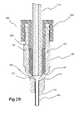
- FIG. 2Aillustrates a cross-sectional view of a fluid path connector system of the present invention in a disconnected state.
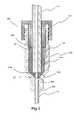
- FIG. 2Billustrates a cross-sectional view of a fluid path connector system of the present invention in a connected state.
- FIG. 3illustrates another embodiment of a fluid path connector system of the present invention wherein an elastomeric sealing element extends beyond a length of conduit to which the sealing element is attached.
- FIG. 4illustrates an example of needle misalignment and the resultant flow restriction that occurs with current needle assembly procedures in the case of, for example, a female luer-type connector.
- sealing elementincludes a plurality of such sealing elements and equivalents thereof known to those skilled in the art, and so forth, and reference to “the sealing element” is a reference to one or more such sealing elements and equivalents thereof known to those skilled in the art, and so forth.
- any component with which a fluid comes into contact during, for example, a fluid delivery or transport procedureis considered part of the fluid path.
- tubing sets and other fluid path elementshave no specific requirements other than containing system pressure without leaking and compatibility with the injection fluids.
- numerous currently available fluid path elementsincluding, for example, tubing sets and connectors for use therewith, such as, for example, luer fittings or connectors) have serious shortfalls.
- turbulent stressescontribute strongly to mechanical trauma of cells.
- Conditions that contribute to or promote turbulence, including wall irregularities, abrupt changes in tube dimensions, and disturbed flow upstream of a region of interest,are common in current practice, as illustrated in the luer connector in FIGS. 1A through 1C . Wall irregularities and abrupt or sharp transitions can also result in clogging.
- cell damageand/or damage to other sensitive fluid components resulting from hydrodynamic forces during handling and delivery of injection fluid, as well as clogging, are preferably minimized by reducing the occurrence of or eliminating such conditions to, for example, improve therapeutic value. Cumulative and peak shear stresses are preferably reduced or minimized.
- luer fittingare widely used as connectors in connection with medical tubing sets and other medical components.
- the design of luer fittingscause the formation of small volumes of fluid that are not in the direct fluid path. That is, there are small volumes in the luer connector wherein material can collect and not be removed by a flush.
- These common luer fittingsare not designed to maintain constant uniform diameter throughout the system.
- devices and systems of the present inventionprovide for attachment of conduit such as elastomeric tubing to a connector.
- the connectorcan, for example, include a male or female luer-type connector to which a patient interface in the form of needle 200 is in fluid connection.
- Hydrodynamic forcescan, for example, be reduced by providing for gradual transition within and between all fluid path elements.
- One goal of the devices and systems of the present inventionis thus to limit sharp transitions in the fluid path that can damage the cells (and/or other fluid components) being delivered. Eliminating sharp transitions can also assist in preventing clogging, particularly where sharp transitions result in a projecting obstruction in the flow path.
- Another goalis to reduce residual volume within the system. As described above, such extra volume can provide space for cells and/other fluid components to collect.
- first cooperating connector 320 and second cooperating connector 340were formed from a polymeric material such as vinyl, polyvinyl chloride (PVC), PEBAX® (a polyether block amide available from Arkema, Inc. of Philadelphia, Pa.) etc. or a metallic material such as stainless steel.
- PVCpolyvinyl chloride
- PEBAX®a polyether block amide available from Arkema, Inc. of Philadelphia, Pa.
- Conduit 170such as elastomeric tubing fabricated from vinyl, PVC, PEBAX, C-FLEX® (a silicone-modified styrenic thermoplastic elastomer, available from Consolidated Polymer Technologies, Inc. of Clearwater, Fla.), etc., as known in the medical arts, can be placed in, for example, removable fluid connection with an outlet 110 of syringe 100 .
- syringe 100includes a barrel 130 and a plunger 140 slidably disposed within barrel 130 to pressurize fluid within barrel 130 .
- Syringe 100can, for example, be operated manually via a plunger extension 142 as known in the art.
- syringe 100can be placed in operative connection with an injector 150 including a powered drive mechanism 160 , which can, for example, cooperate with plunger extension 142 or with plunger 140 to pressurize fluid within syringe barrel 130 .
- injector systems for delivery of, for example, cellsare disclosed, for example, in Published PCT International Patent Application No. WO/2007/053779, the disclosure of which is incorporated herein by reference.
- conduit 170has attached to the end thereof opposite the end attached to syringe outlet 110 a compressible sealing element 180 .
- sealing element 180included or was formed of an elastomeric material such as vinyl, PVC, PEBAX, C-FLEX, silicone, polyurethane etc.
- Sealing element 180can, for example, be generally cylindrical in shape and dimensioned to be concentric with the conduit or tubing 170 .
- elastomeric sealing element 180was overmolded onto tubing 170 , thereby eliminating the need for an adhesive. Sealing element 180 can alternatively be formed integrally and of the same material as conduit 170 .
- a distal end of sealing element 180can, for example, be flush with the distal end of conduit or tubing 170 or extend beyond the distal end of conduit or tubing with a hole aligned with the ID of the tubing.
- the base of distal end of sealing element 180can be shaped, for example, tapered, to generally match the inside surface of the second cooperating connector 340 , with which it comes into contact upon connection of first cooperating connector 320 and second cooperating connector 340 .
- Tapered section 182provides a sealing surface between surface 344 of second cooperating connector 340 and sealing element 180 .
- first cooperating connector 320(a cap or male luer-type cooperating connector) includes a passage 324 through which conduit or tubing 170 passes.
- a distal end surface 328 of first cooperating connectorcontacts a proximal end surface or shoulder 184 of sealing element 180 to compress sealing element 180 and to lock it in place within second cooperating connector 340 (a female luer type cooperating connector).
- second cooperating connector 340engages threading 332 (for example, luer-type threading as known in the arts) of first cooperating connector 320 , distal end surface 328 on a boss of first cooperating connector contacts surface 184 of sealing element 180 , forcing tapered section 182 of sealing element 180 against tapered surface/base 344 of second cooperating connector 340 .
- the inner diameter of second cooperating connector 340can be made sufficiently large to prevent locking tapers when connector 300 is connected or assembled.
- conduit or tubing 170is positioned more closely to a flow path opening 352 of second cooperating connector 340 , thereby reducing potential lost volume as described in connection with FIGS. 1A through 1C .
- extending a sealing element 140 a beyond the end of conduit or tubing 170 and matching the dimension of a passage 148 a within sealing element 140 a to passage 352can virtually eliminate such potential lost volume.
- the interconnection between second cooperating connector 340 and the downstream fluid path element attached theretois also designed to reduce or eliminate sharp flow transitions (which can, for example, damage cells and/or other fluid components being administered). Sharp transitions can, for example, occur between connection of any two fluid path elements or internally within a particular fluid path element.
- the distal end or tip of a female luer-type connector 1 b(see FIG. 4 ) is formed as a solid piece of polymeric or metallic material and is subsequently custom machined to accommodate the fluid path element to be attached thereto, for example, various needle shapes and sizes.
- a hole 5is machined through the luer tip matching the inner diameter of needle 10 to be attached.
- a second hole 8slightly larger than the outer diameter of needle 10 , is then drilled into the front of the luer tip, leaving a small length of original through hole 5 . Needle 10 is then inserted into larger hole 8 and welded or soldered into place.
- needle 10may not be centered with respect to through hole 5 , thereby exposing an edge of needle 10 to the fluid path as illustrated in FIG. 4 .
- drilling through hole 5 to have a smaller diametercould potentially eliminate exposure of the needle edge to through hole 5 , decreasing the diameter of through hole 5 will create a flow restriction.
- proximal end 210 of needle 200is flared to create a larger opening at the entrance of needle 200 (see, for example, FIG. 2A ).
- This flaremoves the perimeter of edge of needle 200 further away from the outer edge of through hole 352 of second cooperating connector 348 .
- the perimeter of edge of proximal end 210 of needle 200will not be exposed to the fluid path.
- [[the]] at least a portion of the outer diameter or OD of needle 200 downstream (that is toward the needle tip or distal end) from flared proximal end 210was effectively enlarged to the same diameter or a greater diameter than the outer perimeter of the flare by sliding a bushing or sleeve 220 (for example, formed from a material such as stainless steel) over distal end 230 of needle 200 until it contacted flare end 210 .
- the outer diameter of sleeve 200can, for example, be dimensioned appropriately for (for example, slightly smaller than) the diameter of mounting hole 354 in second cooperating connector 340 , while the inner diameter is dimensioned appropriately for proper mounting to needle 200 .
- the length of sleeve 220can, for example, be at least as long as required to engage the entire length of mounting hole 354 .
- Sleeve 220can, for example, be attached by adhering, welding or soldering to needle 200 .
- the resultant needle assemblyis then inserted into second cooperating connector (as, for example, illustrated in FIG. 2A ), forcing the flare against the flange located at the base of mounting hole 354 to effect a seal.
- second cooperating connectorwas formed from a metal such as stainless steel
- second cooperating connector 340was then, for example, soldered or welded to sleeve 220 .
- the design of the present inventioneliminates both any potential mismatch between needle 200 and through hole 352 and any potential flow restriction of the typical needle (or other flow path element) connection.
- needle 200was flared at an included angle of 20° to a maximum diameter range of 0.038-0.041 inches. This flaring enlarged the opening of needle 200 to 0.025 inches from its 0.020 inch nominal inner diameter.
- the outer diameter of mounting sleeve 220was 0.042 inches to approximately match the maximum flare diameter of 0.041 inches.
- Mounting sleeve 220also functioned to stiffen needle 200 and was fabricated to run nearly the entire length of needle 200 in several embodiments.
- Mounting hole 354 in second cooperating connector 340had a maximum diametric clearance of 0.0020 inches between the outer diameter of sleeve 220 to accommodate the soldering operation.
- a 0.020 inch ⁇ 0.001 diameter holeprovided an opening from second cooperating connector 340 into needle 200 .
- the total “misalignment” between the opening of needle 200 and through hole 352could be 0.003 inches.
- Flaring needle 200thus provided a margin of 0.005 inches over the nominal diameter, thereby guaranteeing the needle edge stayed away from the lip of through hole 352 .
Landscapes
- Health & Medical Sciences (AREA)
- Heart & Thoracic Surgery (AREA)
- Pulmonology (AREA)
- Engineering & Computer Science (AREA)
- Anesthesiology (AREA)
- Biomedical Technology (AREA)
- Hematology (AREA)
- Life Sciences & Earth Sciences (AREA)
- Animal Behavior & Ethology (AREA)
- General Health & Medical Sciences (AREA)
- Public Health (AREA)
- Veterinary Medicine (AREA)
- Infusion, Injection, And Reservoir Apparatuses (AREA)
Abstract
Description
Claims (18)
Priority Applications (1)
| Application Number | Priority Date | Filing Date | Title |
|---|---|---|---|
| US12/206,123US8551074B2 (en) | 2008-09-08 | 2008-09-08 | Connector system having a compressible sealing element and a flared fluid path element |
Applications Claiming Priority (1)
| Application Number | Priority Date | Filing Date | Title |
|---|---|---|---|
| US12/206,123US8551074B2 (en) | 2008-09-08 | 2008-09-08 | Connector system having a compressible sealing element and a flared fluid path element |
Publications (2)
| Publication Number | Publication Date |
|---|---|
| US20100063481A1 US20100063481A1 (en) | 2010-03-11 |
| US8551074B2true US8551074B2 (en) | 2013-10-08 |
Family
ID=41799880
Family Applications (1)
| Application Number | Title | Priority Date | Filing Date |
|---|---|---|---|
| US12/206,123Expired - Fee RelatedUS8551074B2 (en) | 2008-09-08 | 2008-09-08 | Connector system having a compressible sealing element and a flared fluid path element |
Country Status (1)
| Country | Link |
|---|---|
| US (1) | US8551074B2 (en) |
Cited By (6)
| Publication number | Priority date | Publication date | Assignee | Title |
|---|---|---|---|---|
| US20110288442A1 (en)* | 2008-07-18 | 2011-11-24 | Jean-Marc Reymond | Multipurpose Male Fluidic Coupling For A Coupling Device And Device Such As This Incorporating It |
| US9707342B2 (en) | 2012-06-07 | 2017-07-18 | Bayer Healthcare | Shield adapted to fit medical injector syringe |
| US9750953B2 (en) | 2008-06-06 | 2017-09-05 | Bayer Healthcare Llc | Apparatus and methods for delivery of fluid injection boluses to patients and handling harmful fluids |
| US9889288B2 (en) | 2012-06-07 | 2018-02-13 | Bayer Healthcare Llc | Tubing connectors |
| US10272263B2 (en) | 2012-06-07 | 2019-04-30 | Bayer Healthcare Llc | Radiopharmaceutical delivery and tube management system |
| US10335556B2 (en) | 2013-12-06 | 2019-07-02 | Genentech, Inc. | Apparatus and methods for low-volume medicament delivery |
Families Citing this family (11)
| Publication number | Priority date | Publication date | Assignee | Title |
|---|---|---|---|---|
| US10058642B2 (en) | 2004-04-05 | 2018-08-28 | Bluesky Medical Group Incorporated | Reduced pressure treatment system |
| ES2666945T3 (en)* | 2009-06-24 | 2018-05-08 | Becton Dickinson France | Connection set for a drug delivery device and manufacturing method of said set |
| EP2456355B1 (en) | 2009-07-20 | 2016-09-14 | Optiscan Biomedical Corporation | Adjustable connector and dead space reduction |
| WO2011140073A2 (en) | 2010-05-03 | 2011-11-10 | Optiscan Biomedical Corporation | Adjustable connector, improved fluid flow and reduced clotting risk |
| US9039592B2 (en) | 2012-06-07 | 2015-05-26 | Bayer Medical Care Inc. | Radiopharmaceutical delivery device |
| US9901725B2 (en) | 2012-10-01 | 2018-02-27 | Bayer Healthcare Llc | Overmolded medical connector tubing and method |
| US9433728B2 (en) | 2013-03-01 | 2016-09-06 | Bayer Healthcare Llc | Valveless pharmaceutical infusion system |
| US20150091299A1 (en)* | 2013-09-27 | 2015-04-02 | General Electric Company | Connector to reduce a fluid volume when mating with a counterpart |
| US20160361235A1 (en)* | 2015-06-11 | 2016-12-15 | Covidien Lp | Adapter assembly for enteral feeding |
| AU2019270193B2 (en)* | 2018-05-18 | 2025-02-27 | Bard Peripheral Vascular, Inc. | Connector assemblies |
| AU2019270180B2 (en) | 2018-05-18 | 2024-10-24 | Bard Peripheral Vascular, Inc. | Systems and methods for determining flow parameters of administered fluid from radioembolization delivery device |
Citations (28)
| Publication number | Priority date | Publication date | Assignee | Title |
|---|---|---|---|---|
| US5004457A (en) | 1988-12-02 | 1991-04-02 | The United States Of Americas As Represented By The Secretary Of The Department Of Health And Human Services | Tissue transplantation system |
| WO1992006645A1 (en) | 1990-10-19 | 1992-04-30 | St. Louis University | Surgical probe locating system for head use |
| WO1994023647A1 (en) | 1993-04-22 | 1994-10-27 | Pixsys, Inc. | System for locating relative positions of objects |
| WO1994024933A1 (en) | 1993-04-26 | 1994-11-10 | St. Louis University | Indicating the position of a surgical probe |
| WO1995021643A1 (en) | 1994-02-09 | 1995-08-17 | Matef | Low flow-rate tubing device and pharmaceutical infusion apparatus using same |
| WO1996011624A2 (en) | 1994-10-07 | 1996-04-25 | St. Louis University | Surgical navigation systems including reference and localization frames |
| US5795340A (en)* | 1994-02-05 | 1998-08-18 | Lang; Volker | Microcatheter set |
| US6299591B1 (en)* | 1995-06-02 | 2001-10-09 | Surgical Design Corporation | Phacoemulsification handpiece, sleeve, and tip |
| US6347240B1 (en) | 1990-10-19 | 2002-02-12 | St. Louis University | System and method for use in displaying images of a body part |
| US6503242B1 (en) | 1996-04-30 | 2003-01-07 | Medtronic, Inc. | Therapeutic method for treatment of Alzheimer's disease |
| US20030032940A1 (en)* | 2001-08-10 | 2003-02-13 | Doyle Mark C. | Valved male luer |
| US6565551B1 (en)* | 1997-06-13 | 2003-05-20 | Micro Therapeutics, Inc. | Contoured syringe and novel luer hub and methods for embolizing blood vessels |
| US6641574B2 (en)* | 1999-06-04 | 2003-11-04 | Marcelo Badia Segura | Connecting devices for catheters, perfusion equipment and systems for perfusing or draining liquids in the human body |
| US20040030250A1 (en) | 2000-06-22 | 2004-02-12 | Duncan Stewart | Injection system for gene delivery |
| US6709427B1 (en) | 1999-08-05 | 2004-03-23 | Kensey Nash Corporation | Systems and methods for delivering agents into targeted tissue of a living being |
| US20040172006A1 (en)* | 2003-02-28 | 2004-09-02 | Bonaldo Jean M. | Needleless Luer activated medical connector |
| US20040191225A1 (en) | 2002-08-06 | 2004-09-30 | Dinsmore Jonathan H. | Injection system |
| US20040210196A1 (en) | 2001-07-27 | 2004-10-21 | Bush Jr Charles L. | Luer connector assembly |
| US20050085790A1 (en) | 2003-09-15 | 2005-04-21 | James Guest | Method and system for cellular transplantation |
| US20050225082A1 (en) | 2002-10-10 | 2005-10-13 | Vygon | Fluid connector for medical use and uses thereof |
| US6955660B2 (en)* | 2002-09-09 | 2005-10-18 | Michael Alan Fisher | Internal expansion syringe adaptor |
| US7137969B1 (en) | 1999-09-09 | 2006-11-21 | Queen Elizabeth Ii, Health Sciences Centre | Neural transplantation delivery system |
| WO2007053779A2 (en) | 2005-11-04 | 2007-05-10 | Medrad, Inc. | Delivery of agents to tissue |
| WO2007064937A1 (en) | 2005-12-02 | 2007-06-07 | University Of Rochester | Image-guided therapy delivery and diagnostic needle system |
| WO2007065013A2 (en) | 2005-12-02 | 2007-06-07 | The Johns Hopkins University | Multi imager compatible robot for image-guided interventions, automated brachytherapy seed delivery apparatus and methods and systems related thereto |
| US20080086111A1 (en) | 2006-10-09 | 2008-04-10 | Medrad, Inc. | Fluid delivery systems and volume metering in cell delivery |
| US20080294096A1 (en) | 2005-11-04 | 2008-11-27 | Medrad Inc. | Delivery of Agents Such as Cells to Tissue |
| US20090012497A1 (en) | 2006-12-29 | 2009-01-08 | Medrad, Inc. | Systems and methods of delivering a dilated slurry to a patient |
- 2008
- 2008-09-08USUS12/206,123patent/US8551074B2/ennot_activeExpired - Fee Related
Patent Citations (41)
| Publication number | Priority date | Publication date | Assignee | Title |
|---|---|---|---|---|
| US5004457A (en) | 1988-12-02 | 1991-04-02 | The United States Of Americas As Represented By The Secretary Of The Department Of Health And Human Services | Tissue transplantation system |
| WO1992006645A1 (en) | 1990-10-19 | 1992-04-30 | St. Louis University | Surgical probe locating system for head use |
| US7072704B2 (en) | 1990-10-19 | 2006-07-04 | St. Louis University | System for indicating the position of a surgical probe within a head on an image of the head |
| US5383454A (en) | 1990-10-19 | 1995-01-24 | St. Louis University | System for indicating the position of a surgical probe within a head on an image of the head |
| US6678545B2 (en) | 1990-10-19 | 2004-01-13 | Saint Louis University | System for determining the position in a scan image corresponding to the position of an imaging probe |
| US6463319B1 (en) | 1990-10-19 | 2002-10-08 | St. Louis University | System for indicating the position of a surgical probe within a head on an image of the head |
| US5383454B1 (en) | 1990-10-19 | 1996-12-31 | Univ St Louis | System for indicating the position of a surgical probe within a head on an image of the head |
| US5622170A (en) | 1990-10-19 | 1997-04-22 | Image Guided Technologies, Inc. | Apparatus for determining the position and orientation of an invasive portion of a probe inside a three-dimensional body |
| US6347240B1 (en) | 1990-10-19 | 2002-02-12 | St. Louis University | System and method for use in displaying images of a body part |
| US5891034A (en) | 1990-10-19 | 1999-04-06 | St. Louis University | System for indicating the position of a surgical probe within a head on an image of the head |
| US5920395A (en) | 1993-04-22 | 1999-07-06 | Image Guided Technologies, Inc. | System for locating relative positions of objects in three dimensional space |
| WO1994023647A1 (en) | 1993-04-22 | 1994-10-27 | Pixsys, Inc. | System for locating relative positions of objects |
| US5871445A (en) | 1993-04-26 | 1999-02-16 | St. Louis University | System for indicating the position of a surgical probe within a head on an image of the head |
| WO1994024933A1 (en) | 1993-04-26 | 1994-11-10 | St. Louis University | Indicating the position of a surgical probe |
| US5795340A (en)* | 1994-02-05 | 1998-08-18 | Lang; Volker | Microcatheter set |
| WO1995021643A1 (en) | 1994-02-09 | 1995-08-17 | Matef | Low flow-rate tubing device and pharmaceutical infusion apparatus using same |
| WO1996011624A2 (en) | 1994-10-07 | 1996-04-25 | St. Louis University | Surgical navigation systems including reference and localization frames |
| US6236875B1 (en) | 1994-10-07 | 2001-05-22 | Surgical Navigation Technologies | Surgical navigation systems including reference and localization frames |
| US6299591B1 (en)* | 1995-06-02 | 2001-10-09 | Surgical Design Corporation | Phacoemulsification handpiece, sleeve, and tip |
| US6503242B1 (en) | 1996-04-30 | 2003-01-07 | Medtronic, Inc. | Therapeutic method for treatment of Alzheimer's disease |
| US6565551B1 (en)* | 1997-06-13 | 2003-05-20 | Micro Therapeutics, Inc. | Contoured syringe and novel luer hub and methods for embolizing blood vessels |
| US6641574B2 (en)* | 1999-06-04 | 2003-11-04 | Marcelo Badia Segura | Connecting devices for catheters, perfusion equipment and systems for perfusing or draining liquids in the human body |
| US6709427B1 (en) | 1999-08-05 | 2004-03-23 | Kensey Nash Corporation | Systems and methods for delivering agents into targeted tissue of a living being |
| US7137969B1 (en) | 1999-09-09 | 2006-11-21 | Queen Elizabeth Ii, Health Sciences Centre | Neural transplantation delivery system |
| US20040030250A1 (en) | 2000-06-22 | 2004-02-12 | Duncan Stewart | Injection system for gene delivery |
| US20040210196A1 (en) | 2001-07-27 | 2004-10-21 | Bush Jr Charles L. | Luer connector assembly |
| US20030032940A1 (en)* | 2001-08-10 | 2003-02-13 | Doyle Mark C. | Valved male luer |
| US20040191225A1 (en) | 2002-08-06 | 2004-09-30 | Dinsmore Jonathan H. | Injection system |
| US6955660B2 (en)* | 2002-09-09 | 2005-10-18 | Michael Alan Fisher | Internal expansion syringe adaptor |
| US20050225082A1 (en) | 2002-10-10 | 2005-10-13 | Vygon | Fluid connector for medical use and uses thereof |
| US20040172006A1 (en)* | 2003-02-28 | 2004-09-02 | Bonaldo Jean M. | Needleless Luer activated medical connector |
| US20050085790A1 (en) | 2003-09-15 | 2005-04-21 | James Guest | Method and system for cellular transplantation |
| US7666177B2 (en) | 2003-09-15 | 2010-02-23 | James Guest | Method and system for cellular transplantation in the spinal cord |
| WO2007053779A2 (en) | 2005-11-04 | 2007-05-10 | Medrad, Inc. | Delivery of agents to tissue |
| US20070106208A1 (en) | 2005-11-04 | 2007-05-10 | Medrad, Inc. | Delivery of agents to tissue |
| WO2007056247A2 (en) | 2005-11-04 | 2007-05-18 | Medrad, Inc. | Delivery of agents such as cells to tissue |
| US20080294096A1 (en) | 2005-11-04 | 2008-11-27 | Medrad Inc. | Delivery of Agents Such as Cells to Tissue |
| WO2007064937A1 (en) | 2005-12-02 | 2007-06-07 | University Of Rochester | Image-guided therapy delivery and diagnostic needle system |
| WO2007065013A2 (en) | 2005-12-02 | 2007-06-07 | The Johns Hopkins University | Multi imager compatible robot for image-guided interventions, automated brachytherapy seed delivery apparatus and methods and systems related thereto |
| US20080086111A1 (en) | 2006-10-09 | 2008-04-10 | Medrad, Inc. | Fluid delivery systems and volume metering in cell delivery |
| US20090012497A1 (en) | 2006-12-29 | 2009-01-08 | Medrad, Inc. | Systems and methods of delivering a dilated slurry to a patient |
Cited By (8)
| Publication number | Priority date | Publication date | Assignee | Title |
|---|---|---|---|---|
| US9750953B2 (en) | 2008-06-06 | 2017-09-05 | Bayer Healthcare Llc | Apparatus and methods for delivery of fluid injection boluses to patients and handling harmful fluids |
| US20110288442A1 (en)* | 2008-07-18 | 2011-11-24 | Jean-Marc Reymond | Multipurpose Male Fluidic Coupling For A Coupling Device And Device Such As This Incorporating It |
| US8876733B2 (en)* | 2008-07-18 | 2014-11-04 | Commissariat A L'energie Atomique Et Aux Energies Alternatives | Multipurpose male fluidic coupling for a coupling device and device such as this incorporating it |
| US9707342B2 (en) | 2012-06-07 | 2017-07-18 | Bayer Healthcare | Shield adapted to fit medical injector syringe |
| US9889288B2 (en) | 2012-06-07 | 2018-02-13 | Bayer Healthcare Llc | Tubing connectors |
| US10272263B2 (en) | 2012-06-07 | 2019-04-30 | Bayer Healthcare Llc | Radiopharmaceutical delivery and tube management system |
| US10335556B2 (en) | 2013-12-06 | 2019-07-02 | Genentech, Inc. | Apparatus and methods for low-volume medicament delivery |
| US11844938B2 (en) | 2013-12-06 | 2023-12-19 | Genentech, Inc. | Apparatus and methods for low-volume medicament delivery |
Also Published As
| Publication number | Publication date |
|---|---|
| US20100063481A1 (en) | 2010-03-11 |
Similar Documents
| Publication | Publication Date | Title |
|---|---|---|
| US8551074B2 (en) | Connector system having a compressible sealing element and a flared fluid path element | |
| US8343113B2 (en) | Medical valve assembly | |
| US11759619B2 (en) | Needleless access connectors and valve elements therefor | |
| US6651956B2 (en) | Slit-type swabable valve | |
| US5520665A (en) | Connecting apparatus for medical conduits | |
| USRE43142E1 (en) | Needleless connector | |
| PL181486B1 (en) | Needle-less connector for distribution of fluids, especially parenteral ones | |
| AU2002359895A1 (en) | Slit-type swabable valve | |
| IL180473A (en) | Method and systems for providing an infusion device interface | |
| US10188807B2 (en) | Low residual volume syringe/conduit combination and syringe for such a syringe/conduit combination | |
| EP3213793A1 (en) | Automatic anti-free-flow valve for medical pumps | |
| HK1101362B (en) | Method and system for providing an infusion device interface |
Legal Events
| Date | Code | Title | Description |
|---|---|---|---|
| AS | Assignment | Owner name:MEDRAD, INC.,PENNSYLVANIA Free format text:ASSIGNMENT OF ASSIGNORS INTEREST;ASSIGNORS:HOFFMAN, RAYMOND C.;RHINEHART, EDWARD J.;COWAN, KEVIN P.;AND OTHERS;REEL/FRAME:021494/0983 Effective date:20080904 Owner name:MEDRAD, INC., PENNSYLVANIA Free format text:ASSIGNMENT OF ASSIGNORS INTEREST;ASSIGNORS:HOFFMAN, RAYMOND C.;RHINEHART, EDWARD J.;COWAN, KEVIN P.;AND OTHERS;REEL/FRAME:021494/0983 Effective date:20080904 | |
| AS | Assignment | Owner name:BAYER SCHERING PHARMA AG,GERMANY Free format text:ASSIGNMENT OF ASSIGNORS INTEREST;ASSIGNOR:MEDRAD, INC.;REEL/FRAME:022140/0465 Effective date:20090119 Owner name:BAYER SCHERING PHARMA AG, GERMANY Free format text:ASSIGNMENT OF ASSIGNORS INTEREST;ASSIGNOR:MEDRAD, INC.;REEL/FRAME:022140/0465 Effective date:20090119 | |
| AS | Assignment | Owner name:BAYER PHARMA AKTIENGESELLSCHAFT, GERMANY Free format text:CHANGE OF NAME;ASSIGNOR:BAYER SCHERING PHARMA AKTIENGESELLSCHAFT;REEL/FRAME:031099/0170 Effective date:20110701 | |
| STCF | Information on status: patent grant | Free format text:PATENTED CASE | |
| AS | Assignment | Owner name:BAYER HEALTHCARE LLC, NEW JERSEY Free format text:ASSIGNMENT OF ASSIGNORS INTEREST;ASSIGNOR:BAYER MEDICAL CARE, INC.;REEL/FRAME:036965/0244 Effective date:20151019 | |
| FPAY | Fee payment | Year of fee payment:4 | |
| FEPP | Fee payment procedure | Free format text:MAINTENANCE FEE REMINDER MAILED (ORIGINAL EVENT CODE: REM.); ENTITY STATUS OF PATENT OWNER: LARGE ENTITY | |
| LAPS | Lapse for failure to pay maintenance fees | Free format text:PATENT EXPIRED FOR FAILURE TO PAY MAINTENANCE FEES (ORIGINAL EVENT CODE: EXP.); ENTITY STATUS OF PATENT OWNER: LARGE ENTITY | |
| STCH | Information on status: patent discontinuation | Free format text:PATENT EXPIRED DUE TO NONPAYMENT OF MAINTENANCE FEES UNDER 37 CFR 1.362 | |
| FP | Lapsed due to failure to pay maintenance fee | Effective date:20211008 |