US8550223B2 - Methods and apparatus for position sensitive suspension dampening - Google Patents
Methods and apparatus for position sensitive suspension dampeningDownload PDFInfo
- Publication number
- US8550223B2 US8550223B2US12/463,927US46392709AUS8550223B2US 8550223 B2US8550223 B2US 8550223B2US 46392709 AUS46392709 AUS 46392709AUS 8550223 B2US8550223 B2US 8550223B2
- Authority
- US
- United States
- Prior art keywords
- damper
- fluid
- bottom out
- valve
- cup
- Prior art date
- Legal status (The legal status is an assumption and is not a legal conclusion. Google has not performed a legal analysis and makes no representation as to the accuracy of the status listed.)
- Active
Links
- 238000000034methodMethods0.000titleabstractdescription7
- 239000000725suspensionSubstances0.000titledescription6
- 239000012530fluidSubstances0.000claimsabstractdescription95
- 230000006835compressionEffects0.000claimsabstractdescription49
- 238000007906compressionMethods0.000claimsabstractdescription49
- 238000004891communicationMethods0.000claimsabstractdescription14
- 230000035939shockEffects0.000claimsdescription40
- 239000006096absorbing agentSubstances0.000claimsdescription32
- 238000007789sealingMethods0.000claims1
- 210000002445nippleAnatomy0.000description8
- 230000007246mechanismEffects0.000description5
- 230000002441reversible effectEffects0.000description5
- 238000013016dampingMethods0.000description4
- 230000000694effectsEffects0.000description2
- 230000036316preloadEffects0.000description2
- 238000013459approachMethods0.000description1
- 238000006073displacement reactionMethods0.000description1
- 238000005242forgingMethods0.000description1
- 238000007373indentationMethods0.000description1
- 230000003993interactionEffects0.000description1
- 230000013011matingEffects0.000description1
- 230000000116mitigating effectEffects0.000description1
Images


Classifications
- F—MECHANICAL ENGINEERING; LIGHTING; HEATING; WEAPONS; BLASTING
- F16—ENGINEERING ELEMENTS AND UNITS; GENERAL MEASURES FOR PRODUCING AND MAINTAINING EFFECTIVE FUNCTIONING OF MACHINES OR INSTALLATIONS; THERMAL INSULATION IN GENERAL
- F16F—SPRINGS; SHOCK-ABSORBERS; MEANS FOR DAMPING VIBRATION
- F16F9/00—Springs, vibration-dampers, shock-absorbers, or similarly-constructed movement-dampers using a fluid or the equivalent as damping medium
- F16F9/32—Details
- F16F9/48—Arrangements for providing different damping effects at different parts of the stroke
- B—PERFORMING OPERATIONS; TRANSPORTING
- B60—VEHICLES IN GENERAL
- B60G—VEHICLE SUSPENSION ARRANGEMENTS
- B60G13/00—Resilient suspensions characterised by arrangement, location or type of vibration dampers
- B60G13/02—Resilient suspensions characterised by arrangement, location or type of vibration dampers having dampers dissipating energy, e.g. frictionally
- B60G13/06—Resilient suspensions characterised by arrangement, location or type of vibration dampers having dampers dissipating energy, e.g. frictionally of fluid type
- B60G13/08—Resilient suspensions characterised by arrangement, location or type of vibration dampers having dampers dissipating energy, e.g. frictionally of fluid type hydraulic
- B—PERFORMING OPERATIONS; TRANSPORTING
- B60—VEHICLES IN GENERAL
- B60G—VEHICLE SUSPENSION ARRANGEMENTS
- B60G17/00—Resilient suspensions having means for adjusting the spring or vibration-damper characteristics, for regulating the distance between a supporting surface and a sprung part of vehicle or for locking suspension during use to meet varying vehicular or surface conditions, e.g. due to speed or load
- B60G17/06—Characteristics of dampers, e.g. mechanical dampers
- B60G17/08—Characteristics of fluid dampers
- F—MECHANICAL ENGINEERING; LIGHTING; HEATING; WEAPONS; BLASTING
- F16—ENGINEERING ELEMENTS AND UNITS; GENERAL MEASURES FOR PRODUCING AND MAINTAINING EFFECTIVE FUNCTIONING OF MACHINES OR INSTALLATIONS; THERMAL INSULATION IN GENERAL
- F16F—SPRINGS; SHOCK-ABSORBERS; MEANS FOR DAMPING VIBRATION
- F16F9/00—Springs, vibration-dampers, shock-absorbers, or similarly-constructed movement-dampers using a fluid or the equivalent as damping medium
- F16F9/10—Springs, vibration-dampers, shock-absorbers, or similarly-constructed movement-dampers using a fluid or the equivalent as damping medium using liquid only; using a fluid of which the nature is immaterial
- F16F9/14—Devices with one or more members, e.g. pistons, vanes, moving to and fro in chambers and using throttling effect
- F16F9/16—Devices with one or more members, e.g. pistons, vanes, moving to and fro in chambers and using throttling effect involving only straight-line movement of the effective parts
- F16F9/18—Devices with one or more members, e.g. pistons, vanes, moving to and fro in chambers and using throttling effect involving only straight-line movement of the effective parts with a closed cylinder and a piston separating two or more working spaces therein
- F—MECHANICAL ENGINEERING; LIGHTING; HEATING; WEAPONS; BLASTING
- F16—ENGINEERING ELEMENTS AND UNITS; GENERAL MEASURES FOR PRODUCING AND MAINTAINING EFFECTIVE FUNCTIONING OF MACHINES OR INSTALLATIONS; THERMAL INSULATION IN GENERAL
- F16F—SPRINGS; SHOCK-ABSORBERS; MEANS FOR DAMPING VIBRATION
- F16F9/00—Springs, vibration-dampers, shock-absorbers, or similarly-constructed movement-dampers using a fluid or the equivalent as damping medium
- F16F9/32—Details
- F16F9/3207—Constructional features
- F16F9/3214—Constructional features of pistons
- F—MECHANICAL ENGINEERING; LIGHTING; HEATING; WEAPONS; BLASTING
- F16—ENGINEERING ELEMENTS AND UNITS; GENERAL MEASURES FOR PRODUCING AND MAINTAINING EFFECTIVE FUNCTIONING OF MACHINES OR INSTALLATIONS; THERMAL INSULATION IN GENERAL
- F16F—SPRINGS; SHOCK-ABSORBERS; MEANS FOR DAMPING VIBRATION
- F16F9/00—Springs, vibration-dampers, shock-absorbers, or similarly-constructed movement-dampers using a fluid or the equivalent as damping medium
- F16F9/32—Details
- F16F9/48—Arrangements for providing different damping effects at different parts of the stroke
- F16F9/49—Stops limiting fluid passage, e.g. hydraulic stops or elastomeric elements inside the cylinder which contribute to changes in fluid damping
- B—PERFORMING OPERATIONS; TRANSPORTING
- B60—VEHICLES IN GENERAL
- B60G—VEHICLE SUSPENSION ARRANGEMENTS
- B60G2202/00—Indexing codes relating to the type of spring, damper or actuator
- B60G2202/20—Type of damper
- B60G2202/24—Fluid damper
- B—PERFORMING OPERATIONS; TRANSPORTING
- B60—VEHICLES IN GENERAL
- B60G—VEHICLE SUSPENSION ARRANGEMENTS
- B60G2206/00—Indexing codes related to the manufacturing of suspensions: constructional features, the materials used, procedures or tools
- B60G2206/01—Constructional features of suspension elements, e.g. arms, dampers, springs
- B60G2206/40—Constructional features of dampers and/or springs
- B60G2206/41—Dampers
- B—PERFORMING OPERATIONS; TRANSPORTING
- B60—VEHICLES IN GENERAL
- B60G—VEHICLE SUSPENSION ARRANGEMENTS
- B60G2500/00—Indexing codes relating to the regulated action or device
- B60G2500/10—Damping action or damper
- B60G2500/11—Damping valves
- B60G2500/112—Fluid actuation
- B—PERFORMING OPERATIONS; TRANSPORTING
- B60—VEHICLES IN GENERAL
- B60G—VEHICLE SUSPENSION ARRANGEMENTS
- B60G2500/00—Indexing codes relating to the regulated action or device
- B60G2500/10—Damping action or damper
- B60G2500/11—Damping valves
- B60G2500/114—Damping valves pressure regulating valves
- F—MECHANICAL ENGINEERING; LIGHTING; HEATING; WEAPONS; BLASTING
- F16—ENGINEERING ELEMENTS AND UNITS; GENERAL MEASURES FOR PRODUCING AND MAINTAINING EFFECTIVE FUNCTIONING OF MACHINES OR INSTALLATIONS; THERMAL INSULATION IN GENERAL
- F16F—SPRINGS; SHOCK-ABSORBERS; MEANS FOR DAMPING VIBRATION
- F16F9/00—Springs, vibration-dampers, shock-absorbers, or similarly-constructed movement-dampers using a fluid or the equivalent as damping medium
- F16F9/10—Springs, vibration-dampers, shock-absorbers, or similarly-constructed movement-dampers using a fluid or the equivalent as damping medium using liquid only; using a fluid of which the nature is immaterial
- F16F9/14—Devices with one or more members, e.g. pistons, vanes, moving to and fro in chambers and using throttling effect
- F16F9/16—Devices with one or more members, e.g. pistons, vanes, moving to and fro in chambers and using throttling effect involving only straight-line movement of the effective parts
- F16F9/18—Devices with one or more members, e.g. pistons, vanes, moving to and fro in chambers and using throttling effect involving only straight-line movement of the effective parts with a closed cylinder and a piston separating two or more working spaces therein
- F16F9/19—Devices with one or more members, e.g. pistons, vanes, moving to and fro in chambers and using throttling effect involving only straight-line movement of the effective parts with a closed cylinder and a piston separating two or more working spaces therein with a single cylinder and of single-tube type
- F—MECHANICAL ENGINEERING; LIGHTING; HEATING; WEAPONS; BLASTING
- F16—ENGINEERING ELEMENTS AND UNITS; GENERAL MEASURES FOR PRODUCING AND MAINTAINING EFFECTIVE FUNCTIONING OF MACHINES OR INSTALLATIONS; THERMAL INSULATION IN GENERAL
- F16F—SPRINGS; SHOCK-ABSORBERS; MEANS FOR DAMPING VIBRATION
- F16F9/00—Springs, vibration-dampers, shock-absorbers, or similarly-constructed movement-dampers using a fluid or the equivalent as damping medium
- F16F9/32—Details
- F16F9/3207—Constructional features
- F16F9/3235—Constructional features of cylinders
- F16F9/3242—Constructional features of cylinders of cylinder ends, e.g. caps
Definitions
- Embodiments of the inventiongenerally relate to methods and apparatus for use in vehicle suspension. Particular embodiments of the invention relate to methods and apparatus useful for variable and position sensitive dampening rate in vehicle shock absorbers.
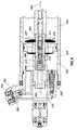
- FIG. 1is a perspective view of a shock absorber 100 , typically used as a rear shock absorber for a motorcycle and fixable at an upper end with a mounting eye 105 to a main frame of a cycle and at a lower end with another mounting eye 110 to a link system beneath a swinging arm.
- the link system(not shown) is designed to leverage the suspension so that initially the suspension feels soft but feels progressively firmer as the shock absorber is compressed further.
- a helical spring 115includes a helical spring 115 , a damper housing 120 with a piston and chamber (not shown) and an external reservoir 125 having a floating piston (not shown) and pressurized gas to compensate for a reduction in volume in the main damper chamber of the shock absorber as the piston shaft 130 moves into the damper body.
- Fluid communication between the main chamber of the damper and the reservoir 125may be via a flow channel including an adjustable needle valve.
- the damperworks in conjunction with the helical spring and controls the speed of movement of the piston shaft by metering incompressible fluid from one side of the damper piston to the other, and additionally from the main chamber to the reservoir, during a compression stroke (and in reverse during the rebound or extension stroke).
- shock absorberslike the one shown in FIG. 1 to enhance their performance.
- One continuing problemis that of a “bottom out” condition where the dampening piston becomes completely retracted due to compressive forces brought about by terrain and the weight of a rider. Additionally problematic is the fact that the dampening fluid typically increases in temperature during use.
- a “bottom out” dampener that may be initially set up to be effective at higher dampening fluid temperaturewill often be too stiff at lower temperatures during initial stages of use (noting that the shock fluid temperature may never even rise to an ideal temperature) creating a harsh ride and poor vehicle handling characteristics.
- a dampener that works well and initially doesn't bottom out too hardmay begin to bottom out as the dampening fluid becomes heated and correspondingly less viscous during use or extended use.
- a shock absorberincludes an additional piston located at an end of the piston shaft and designed to enter a completely closed cup-shaped member as the shock absorber approaches complete compression.
- the arrangementadds an additional fluid metering dampening piston and therefore additional dampening, as the shock nears the end of its stroke.
- U.S. Pat. No. 6,029,958which is also incorporated by reference herein in its entirety, provides an increase in dampening as the shock is compressed by using a pin and hole arrangement.
- the pistonhas an aperture formed in its center and the aperture serves as a fluid path during a first portion of the shock's compression stroke.
- a pin mounted at a bottom end of the chambercontacts the aperture and prevents further fluid communication. In this manner, dampening is increased by eliminating a metering path for the fluid.
- Embodiments of the inventionare generally related to methods and apparatus for use in vehicle suspension. Particular embodiments relate to methods and apparatus useful in position sensitive dampening in a shock absorber for a motorcycle.
- a fluid dampercomprising a damper chamber divided by a piston into a primary compression and a primary rebound chamber.
- a secondary compression chamberis in fluid communication with the damper chamber and an adjustable fluid meter controls fluid flow out of the secondary compression chamber.
- a bottom out cupis provided at a lower end of a damper chamber for operation in conjunction with a bottom out piston.
- the bottom out pistonenters and seals the cup, increased dampening takes place as the path of fluid from the cup back into the compression chamber of the shock is limited, in one embodiment, to a blow off valve and/or a user-adjustable metering valve.
- communicationis selectively permitted between fluid in the sealed bottom out cup and the rebound portion of the chamber via a fluid path(s) formed in the interior of the piston shaft.
- the fluid path in the piston shaftis controlled with a reversible check valve that will permit, in one setting, fluid communication only during the rebound stoke of the piston and shaft.
- FIG. 1is a perspective view of a rear shock absorber including a damper, external reservoir and helical spring.
- FIG. 2is a section view showing a shock absorber with a dampening assembly having a secondary, bottom out dampening assembly.
- FIG. 3Ais a section view showing a bottom out piston entering a bottom out cup during a compression stroke of a shock absorber.
- FIG. 3Bis a section view showing the bottom out cup of FIG. 3A with the bottom out piston fully engaged and sealed therein.
- FIG. 3Cis a section view of the bottom out cup of FIGS. 3A & 3B showing a blow off valve and a user-adjustable metering valve in communication with the bottom out cup.
- FIG. 4is a section view showing the bottom out piston being removed from the cup and a piston shaft having a fluid path formed in its interior for providing fluid communication between the bottom out cup and the rebound portion of the dampening chamber during the rebound stroke.
- FIG. 2is a section view showing a dampening assembly 200 of a shock absorber shown in an axially extended position.
- a dampening piston 210is fixed relative to a shaft 215 , both of which are axially movable relative to a housing or chamber 220 .
- the piston 210is equipped with fluid paths therethrough to permit dampening fluid within the chamber 220 to be metered through the piston 210 . For example, when the shaft 215 moves into the chamber 220 , fluid moves from a first side (the compression portion) to an opposite side (the rebound portion) of the chamber 220 through the paths formed in the piston 210 .
- a bottom out piston 250connected at the end of the shaft 215 and spaced from the dampening piston 210 .
- the bottom out pistonis constructed and arranged to engage a bottom out cup 275 formed at the lower end of the chamber 220 .
- the bottom out cup and bottom out pistonoperate with various dampening devices including a pressure relief or “blow off” valve and a user-adjustable metering valve.
- FIG. 3Ais a section view showing the bottom out piston 250 entering the bottom out cup 275 during a compression stroke of the shock absorber.
- the direction of movement of the piston 250is illustrated by arrow 280 .
- the bottom out pistonincludes a piston ring or dynamic seal 251 for axially slidable engagement with an inner diameter of the bottom out cup 275 .
- the upper end of the bottom out cuphas a diameter that tapers outwards (i.e. larger) permitting, initially in the stroke, some fluid to pass through an annular area formed between the bottom out piston seal 251 and the inner diameter of the cup 275 .
- the piston by-pass flow of fluid through the annular area and into a compression portion 222 of chamber 220is illustrated by arrow 281 .
- FIG. 3Bis a section view showing the bottom out cup 275 of FIG. 3A with the bottom out piston 250 fully engaged therein.
- dampeningis increased because the shaft 215 can only progress further as fluid (e.g. substantially incompressible) is moved from the bottom out cup through one of two paths 301 , 302 leading back into the compression portion 222 of chamber 220 (and ultimately also into side reservoir 125 if one is used).
- fluide.g. substantially incompressible
- FIG. 3Balso shows various adjustable dampening mechanisms that work in conjunction with the bottom out cup and piston.
- a pressure relief or “blow off” valve 300a high speed compression circuit that operates at a blow off threshold, typically due to a relatively rapid event like the rapid compression of the shock absorber.
- the blow-off valve 300selectively allows fluid flow from the bottom out cup 275 to the compression portion 222 of chamber 220 at shaft speeds (in the direction 280 ) that create fluid pressures within the bottom out cup above the blow off threshold pressure during engagement of piston 275 with bottom out cup 275 .
- the blow-off valvegenerally comprises a valve opening, a blow-off valve or piston 300 and a compression spring 305 .
- the blow off pressureis determined by a combination of the spring rate of the spring 305 , the preload on the spring 305 and the area of the blow-off piston 300 that is subject to fluid pressure from the bottom out cup 275 .
- the pistonis forced away from the piston seat and allows fluid to flow through the valve opening and into the compression portion 222 , thus lowering the pressure within the bottom out cup 275 .
- the blow off valve 300is primarily a safety device and is typically set to crack or “blow off”, thereby allowing fluid flow into the compression portion of chamber 200 , at a pressure that is relatively high but still low enough to prevent excess pressure build up in the bottom out cup 275 from damaging the shock or the vehicle in which the shock is integrated.
- a user-adjustable metering valve 350with externally accessible adjustment features.
- the valve 350is operable provide an easily and readily adjustable dampening feature operable with the bottom out chamber 275 and piston 250 .
- FIGS. 3A-Bthe valve 350 is shown in an open position whereby fluid may flow through an orifice 400 .
- FIG. 3Cthe valve is shown in a closed position wherein orifice 400 is fully obstructed.
- the valve 350is disposed in a bore formed in the damper housing cap.
- the valve assemblyconsists of a body 355 , an indexing ring 360 and a nipple portion 370 .
- the body 355includes a slot 375 for a screwdriver head exposed to an area outside the shock absorber and permitting ready access to and adjustment of the valve 350 by a user.
- the body 355includes a hand manipulatable knob in addition to a wrench profile or screwdriver recess. Any suitable turning feature may be included with body 355 for easy external access and adjustment.
- the indexing ring 360consisting of two opposing, outwardly spring-biased balls 380 rotates among indentions formed on an inside diameter of a lock ring 354 . The interaction between the balls and the indentions locks the body 355 at each rotational location until the balls 380 are urged out of the indentations by additional rotational force input by the user.
- the body 355will index at various points of its rotation so that positioning of the body 355 , and the corresponding setting of valve 350 , by the user is maintained against vibration of the shock and the vehicle while in use.
- the body 355rotates, so does the valve or nipple portion 370 at an opposite end of the valve from the head.
- the body 355is rotationally engaged with the nipple 370 .
- a male hex memberextends from an end of the body 355 into a female hex profile bore formed in the nipple 370 .
- Such engagementtransmits rotation from the body 355 to the nipple 370 while allowing axial displacement of the nipple 370 relative to the body 355 .
- the threaded nipple portion 370interacts with mating threads 390 formed on an inside diameter of the bore to transmit axial motion, resulting from rotation and based on the pitch of the threads 390 , of the nipple portion 370 towards and away from an orifice 400 and between a closed and fully open positions.
- blow off valve 300 and the user-adjustable metering valve 350operate independently of each other but each is designed to permit fluid to pass from the bottom out cup 275 to the compression portion 222 of the chamber 220 in order to lessen the increase in dampening effect (i.e. the “increase” being over that due to the piston 210 and the reservoir 125 during the majority of the compression stroke) when the bottom out piston 250 engages the bottom out cup. Even when valve 350 is completely closed with no fluid entering the compression portion of the chamber through the metering valve 350 (i.e.
- the dampening ratewill decrease to some extent when a threshold pressure of blow off valve 300 is reached, thereby opening valve 300 and allowing fluid to flow from the bottom out cup 275 to the compression portion of the chamber 220 via flow path 302 and independently of orifice 400 .
- FIG. 4is a section view showing the piston shaft 215 with another dampening mechanism operable in conjunction with the bottom out cup 275 and piston 250 and also to operate prior to engagement of the piston in the cup.
- the bottom out piston 250is shown being removed from the bottom out cup 275 .
- the piston shaft 215includes a fluid path formed in its interior and provides for fluid communication between the bottom out cup 275 and a rebound portion 221 of the chamber 220 during the rebound stroke.
- the path and direction of flow in the embodimentis illustrated by arrow 465 .
- the pathwinds through a bore in the shaft that is formed coaxially with the centerline of the shaft.
- the fluid path including 455terminates at a lower end of the bottom out piston 250 and at an upper end of the path terminates at an aperture(s) 460 intersecting the path 465 and leading into the chamber 221 .
- shaft 215includes a mounting eye (or clevis) 225 at one end thereof.
- the mounting eye 225includes a valve adjuster 230 which is user-adjustable and movable in and out (e.g. by threaded engagement) of the eye in a direction substantially perpendicular to the longitudinal axis of shaft 215 .
- Shaft 215also includes a coaxially mounted shaft 235 therein, where shaft 235 is axially movable relative to shaft 215 .
- valve adjuster 230contacts an end of shaft 235 and rotational movement of valve adjuster 230 causes axial movement of shaft 235 relative to shaft 215 .
- Such axial movement of shaft 235changes the position of a needle valve 231 inside the shaft and thereby adjusts the low speed fluid flow rate and maximum fluid flow rate though the piston shaft (in the direction that is not blocked by a check valve 475 ) and thereby allows manual adjustment of the dampening rate.
- the shaft 215 of the embodimentis provided with an adjustable and reversible check valve 475 installed at an upper end of the path and permitting fluid to selectively move in one direction while preventing fluid from moving in an opposite direction.
- fluidis only permitted to move toward the lower end of the bottom out piston 250 (as indicated by path arrow 465 ) and is checked in the reverse direction.
- the valve 475is spring loaded to open at a predetermined (set) fluid pressure in the direction of permitted flow (the direction shown by arrow 465 ). Varying spring preload will vary the fluid pressure at which the check valve is set to crack.
- dampening of the shock absorberis reduced in the extending or rebound direction, because the fluid flow through the shaft permits a quicker extension or “rebound” of the shaft by permitting an additional volume of fluid to move from the rebound portion 221 of the chamber 220 to the region below the bottom out piston 250 (which, following bottom out, flows into the bottom out cup below piston 250 ), thus reducing force required to retract the bottom out piston 250 from the cup 275 and therefore, the shaft 215 and permitting a quicker extension.
- the check valve 475is reversed and dampening on the compression stroke is reduced by the allowance of additional fluid flow through the shaft 215 and along path 465 but in an opposite direction from the one shown in FIG. 4 as direction 465 . Reversing the check valve from the shown embodiment results in the valve member 476 and seat 477 being oriented towards the bottom out piston.
- the bore of shaft 215is provided with threads to accept a check valve cartridge assembly 485 .
- the cartridge assembly 485is further secured within the shaft 215 by a threaded nut 486 .
- the cartridge 485 and the nut 486are flush or below flush relative to the lower end of the shaft 215 and fit therein without additional shaft diameter or length, so that there is no interference with the interface between or operation or assembly of the piston 250 and the shaft 215 .
- the shaft 215 having the provision for a modular valve cartridge 485allows for other interchangeable valve configurations without modifying surrounding hardware.
- valve cartridge 485may be equipped with fluid flow resistors (chokes), filters or other micro-fluidic devices as, for example, are illustrated in The Lee Company Technical Hydraulic Handbook, which is copyright 1996 by The Lee Company and entirely incorporated by reference herein, or any suitable combination of the foregoing as may be desirable for the tailoring of flowing fluid characteristics. Further, the inclusion of such cartridge check valve requires no additional length in the overall shaft 215 /piston 250 assembly.
- shock absorber 200 and bottom out featureare configured and operated, at the user's discretion, without the check valve 475 (or cartridge 485 ) installed.
- fluidmay flow along path 465 in either direction, thereby reducing dampening characteristics in both the rebound and compression strokes to the extent allowed by adjustment of the needle valve 231 .
- the needle valvemay be completely closed into an adjacent end of cartridge 485 thereby excluding fluid flow in both directions along path 465 .
- the bottom out chamber or “cup”is located proximate an end of the damping chamber corresponding to the hole though which the shaft enters that chamber.
- a “bottom out piston”surrounds the shaft and is axially movable relative thereto (there though).
- the primary damping pistonincludes a connector which connects it to the bottom out piston and the connector is capable of bearing tension between the two pistons but not compression.
- a simple embodiment of such a connectormay comprise a flexible cable.
- the bottom out pistonis forced into the bottom out cup by direct engagement of the “topping out” primary damping piston at near full extension of the shock absorber. In extended positions of the shock absorber the connector between the primary and bottom out pistons is slack.
- the bottom out cupincludes a metering valve, in principle as described herein, for metering fluid through a path between (into) an interior of the bottom out cup (such interior formed by the cup and the engaged bottom out piston) and (from) the rebound chamber thereby relieving the vacuum while creating an increased damping effect near bottom out. It is contemplated that the “bottom out cup” and “bottom out piston” may include many varied embodiments while retaining adjustability.
- Each dampening mechanism describedis usable with a bottom out cup and piston to provide a variety of selectable and/or adjustable dampening options in a shock absorber near the end of a compression stroke (and some throughout either stroke) or beginning of a rebound stroke.
- Embodiments described hereinmay also be adapted to work with dampeners generally as if the bottom out piston 250 and the bottom out cup described herein where the dampening piston and cylinder.
- the user-adjustable metering valve 350can be set by a user to permit a predetermined amount of fluid to flow between the cup and the compression portion 221 chamber 220 of the damper.
- the blow off valve 250depending upon its setting, permits fluid flow in the event that pressure in the cup exceeds the threshold pressure of the blow off valve circuit.
- Operation of the blow off valveis in part determinable by the setting of the user-adjustable metering valve as its more or less meting of fluid operates to lessen or increase, respectively, the fluid pressure in the bottom out cup.
- the reversible check valve 475 in the hollow shaftcan be arranged to reduce dampening in either the compression or the rebound stroke of the piston.
Landscapes
- Engineering & Computer Science (AREA)
- General Engineering & Computer Science (AREA)
- Mechanical Engineering (AREA)
- Fluid-Damping Devices (AREA)
Abstract
Description
Claims (19)
Priority Applications (8)
| Application Number | Priority Date | Filing Date | Title |
|---|---|---|---|
| US12/463,927US8550223B2 (en) | 2008-05-09 | 2009-05-11 | Methods and apparatus for position sensitive suspension dampening |
| US14/022,030US9303712B2 (en) | 2008-05-09 | 2013-09-09 | Methods and apparatus for position sensitive suspension damping |
| US15/056,940US10054185B2 (en) | 2008-05-09 | 2016-02-29 | Methods and apparatus for position sensitive suspension damping |
| US16/105,639US11131361B2 (en) | 2008-05-09 | 2018-08-20 | Methods and apparatus for position sensitive suspension damping |
| US16/175,656US11306798B2 (en) | 2008-05-09 | 2018-10-30 | Position sensitive suspension damping with an active valve |
| US17/463,102US20210396294A1 (en) | 2008-05-09 | 2021-08-31 | Methods and apparatus for position sensitive suspension damping |
| US17/722,211US20230019929A1 (en) | 2008-05-09 | 2022-04-15 | Position sensitive suspension damping with an active valve |
| US17/722,240US20220389983A1 (en) | 2008-05-09 | 2022-04-15 | Position sensitive suspension damping with an active valve |
Applications Claiming Priority (2)
| Application Number | Priority Date | Filing Date | Title |
|---|---|---|---|
| US5215008P | 2008-05-09 | 2008-05-09 | |
| US12/463,927US8550223B2 (en) | 2008-05-09 | 2009-05-11 | Methods and apparatus for position sensitive suspension dampening |
Related Parent Applications (1)
| Application Number | Title | Priority Date | Filing Date |
|---|---|---|---|
| US16/042,563Continuation-In-PartUS10814689B2 (en) | 2008-05-09 | 2018-07-23 | Method and apparatus for an adjustable damper |
Related Child Applications (1)
| Application Number | Title | Priority Date | Filing Date |
|---|---|---|---|
| US14/022,030ContinuationUS9303712B2 (en) | 2008-05-09 | 2013-09-09 | Methods and apparatus for position sensitive suspension damping |
Publications (2)
| Publication Number | Publication Date |
|---|---|
| US20090277734A1 US20090277734A1 (en) | 2009-11-12 |
| US8550223B2true US8550223B2 (en) | 2013-10-08 |
Family
ID=40940402
Family Applications (5)
| Application Number | Title | Priority Date | Filing Date |
|---|---|---|---|
| US12/463,927ActiveUS8550223B2 (en) | 2008-05-09 | 2009-05-11 | Methods and apparatus for position sensitive suspension dampening |
| US14/022,030Active2029-09-15US9303712B2 (en) | 2008-05-09 | 2013-09-09 | Methods and apparatus for position sensitive suspension damping |
| US15/056,940ActiveUS10054185B2 (en) | 2008-05-09 | 2016-02-29 | Methods and apparatus for position sensitive suspension damping |
| US16/105,639ActiveUS11131361B2 (en) | 2008-05-09 | 2018-08-20 | Methods and apparatus for position sensitive suspension damping |
| US17/463,102AbandonedUS20210396294A1 (en) | 2008-05-09 | 2021-08-31 | Methods and apparatus for position sensitive suspension damping |
Family Applications After (4)
| Application Number | Title | Priority Date | Filing Date |
|---|---|---|---|
| US14/022,030Active2029-09-15US9303712B2 (en) | 2008-05-09 | 2013-09-09 | Methods and apparatus for position sensitive suspension damping |
| US15/056,940ActiveUS10054185B2 (en) | 2008-05-09 | 2016-02-29 | Methods and apparatus for position sensitive suspension damping |
| US16/105,639ActiveUS11131361B2 (en) | 2008-05-09 | 2018-08-20 | Methods and apparatus for position sensitive suspension damping |
| US17/463,102AbandonedUS20210396294A1 (en) | 2008-05-09 | 2021-08-31 | Methods and apparatus for position sensitive suspension damping |
Country Status (2)
| Country | Link |
|---|---|
| US (5) | US8550223B2 (en) |
| EP (2) | EP2116739B1 (en) |
Cited By (37)
| Publication number | Priority date | Publication date | Assignee | Title |
|---|---|---|---|---|
| US9303712B2 (en) | 2008-05-09 | 2016-04-05 | Fox Factory, Inc. | Methods and apparatus for position sensitive suspension damping |
| US20160215846A1 (en)* | 2013-09-24 | 2016-07-28 | Kyb Corporation | Shock absorber and suspension apparatus |
| US20160230835A1 (en)* | 2015-02-06 | 2016-08-11 | Tenneco Automotive Operating Company Inc. | Secondary dampening assembly for shock absorber |
| US9605726B2 (en) | 2015-02-03 | 2017-03-28 | Tenneco Automotive Operating Company Inc. | Secondary dampening assembly for shock absorber |
| EP3461661A2 (en) | 2017-09-29 | 2019-04-03 | Fox Factory, Inc. | Modular electronic damping control |
| US10330171B2 (en) | 2012-05-10 | 2019-06-25 | Fox Factory, Inc. | Method and apparatus for an adjustable damper |
| US10677309B2 (en) | 2011-05-31 | 2020-06-09 | Fox Factory, Inc. | Methods and apparatus for position sensitive suspension damping |
| EP3663605A1 (en) | 2018-10-30 | 2020-06-10 | Fox Factory, Inc. | Position sensitive suspension damping with an active valve |
| US10723409B2 (en) | 2009-01-07 | 2020-07-28 | Fox Factory, Inc. | Method and apparatus for an adjustable damper |
| US10781879B2 (en) | 2009-01-07 | 2020-09-22 | Fox Factory, Inc. | Bypass for a suspension damper |
| US10981429B2 (en) | 2017-09-29 | 2021-04-20 | Fox Factory, Inc. | Electronically controlled sway bar damping link |
| US20210291931A1 (en)* | 2020-03-18 | 2021-09-23 | Honda Motor Co., Ltd. | Saddle-riding type vehicle |
| US11162555B2 (en) | 2008-08-25 | 2021-11-02 | Fox Factory, Inc. | Methods and apparatus for suspension lock out and signal generation |
| US11173765B2 (en) | 2009-01-07 | 2021-11-16 | Fox Factory, Inc. | Method and apparatus for an adjustable damper |
| US11279198B2 (en) | 2009-10-13 | 2022-03-22 | Fox Factory, Inc. | Methods and apparatus for controlling a fluid damper |
| US11279199B2 (en) | 2012-01-25 | 2022-03-22 | Fox Factory, Inc. | Suspension damper with by-pass valves |
| US11299233B2 (en) | 2009-01-07 | 2022-04-12 | Fox Factory, Inc. | Method and apparatus for an adjustable damper |
| US11306798B2 (en) | 2008-05-09 | 2022-04-19 | Fox Factory, Inc. | Position sensitive suspension damping with an active valve |
| US11472252B2 (en) | 2016-04-08 | 2022-10-18 | Fox Factory, Inc. | Electronic compression and rebound control |
| US11499601B2 (en) | 2009-01-07 | 2022-11-15 | Fox Factory, Inc. | Remotely operated bypass for a suspension damper |
| US11519477B2 (en) | 2009-01-07 | 2022-12-06 | Fox Factory, Inc. | Compression isolator for a suspension damper |
| US11549565B2 (en) | 2009-01-07 | 2023-01-10 | Fox Factory, Inc. | Method and apparatus for an adjustable damper |
| US11602971B2 (en)* | 2019-02-22 | 2023-03-14 | Fox Factory, Inc. | Mechanical bypass of electronic valve body |
| US11634003B2 (en) | 2020-12-17 | 2023-04-25 | Fox Factory, Inc. | Automated control system for an electronically controlled sway bar link |
| US11655873B2 (en) | 2009-03-19 | 2023-05-23 | Fox Factory, Inc. | Methods and apparatus for suspension adjustment |
| US11708878B2 (en) | 2010-01-20 | 2023-07-25 | Fox Factory, Inc. | Remotely operated bypass for a suspension damper |
| US11859690B2 (en) | 2009-10-13 | 2024-01-02 | Fox Factory, Inc. | Suspension system |
| US11897571B2 (en) | 2008-11-25 | 2024-02-13 | Fox Factory, Inc. | Seat post |
| US11920655B2 (en) | 2009-03-19 | 2024-03-05 | Fox Factory, Inc. | Methods and apparatus for suspension adjustment |
| US11958328B2 (en) | 2011-09-12 | 2024-04-16 | Fox Factory, Inc. | Methods and apparatus for suspension set up |
| US12083850B2 (en) | 2021-12-20 | 2024-09-10 | Fox Factory, Inc. | Electronically controlled sway bar damping link |
| US12091122B2 (en) | 2009-01-07 | 2024-09-17 | Fox Factory, Inc. | Method and apparatus for an adjustable damper |
| US12103349B2 (en) | 2009-03-19 | 2024-10-01 | Fox Factory, Inc. | Methods and apparatus for selective spring pre-load adjustment |
| US12122205B2 (en) | 2009-01-07 | 2024-10-22 | Fox Factory, Inc. | Active valve for an internal bypass |
| US12270062B2 (en) | 2017-09-08 | 2025-04-08 | Fox Factory, Inc. | Electronically controlled sway bar damping link |
| US12311720B2 (en) | 2022-02-23 | 2025-05-27 | Fox Factory, Inc. | Hydraulic cross-linked suspension |
| US12344059B1 (en)* | 2024-03-15 | 2025-07-01 | Fox Factory, Inc. | Modular clevis mount assembly |
Families Citing this family (50)
| Publication number | Priority date | Publication date | Assignee | Title |
|---|---|---|---|---|
| JP2008190640A (en)* | 2007-02-06 | 2008-08-21 | Soki Hs Kk | Multi-stage adjusting device |
| US10821795B2 (en) | 2009-01-07 | 2020-11-03 | Fox Factory, Inc. | Method and apparatus for an adjustable damper |
| US8511448B2 (en)* | 2010-02-01 | 2013-08-20 | Trek Bicycle Corp. | Bicycle air shock assemblies with tunable suspension performance |
| CA2711199C (en)* | 2010-07-29 | 2013-11-12 | Messier-Dowty Inc. | Hydraulic shimmy damper for aircraft landing gear |
| US10113604B2 (en) | 2012-03-09 | 2018-10-30 | Fox Factory, Inc. | Suspension damper |
| US9228630B2 (en) | 2012-08-27 | 2016-01-05 | Cane Creek Cycling Components | Twin tube style damper with selectable bypass flow passages |
| US8967345B2 (en)* | 2012-09-12 | 2015-03-03 | Msi Defense Solutions, Llc | Adjustable rebound buffer |
| USD734219S1 (en) | 2013-06-06 | 2015-07-14 | öHLINS RACING AB | Rear shock absorber for a bicycle |
| US9758210B2 (en)* | 2013-08-23 | 2017-09-12 | Hayes Bicycle Group, Inc. | Suspension system |
| FR3014978B1 (en)* | 2013-12-16 | 2016-01-22 | Ratier Figeac Soc | ROTATING SHAFT DAMPER, PARTICULARLY FOR CONTROLLING THE OPENING SPEED OF AN AIRCRAFT DOOR |
| US9436682B2 (en)* | 2014-06-24 | 2016-09-06 | Google Inc. | Techniques for machine language translation of text from an image based on non-textual context information from the image |
| US10156280B2 (en) | 2014-09-09 | 2018-12-18 | Push Industries, Incorporated | Control valve to permit adjustability of a shock absorber |
| EP3488121B1 (en) | 2016-07-20 | 2022-03-02 | Elka Suspension Inc. | Position-relative damper assist system |
| US11105390B2 (en) | 2017-08-28 | 2021-08-31 | Qa1 Precision Products, Inc. | Shock absorber with dry valving |
| US11085502B2 (en) | 2017-08-28 | 2021-08-10 | Qa1 Precision Products, Inc. | Bleed needle for a hydraulic system |
| USD869259S1 (en) | 2017-08-28 | 2019-12-10 | Qa1 Precision Products, Inc. | Valve component |
| USD872837S1 (en) | 2017-08-28 | 2020-01-14 | Qa1 Precision Products, Inc. | Bleed needle |
| USD866408S1 (en) | 2017-08-28 | 2019-11-12 | Qa1 Precision Products, Inc. | Shock absorber |
| JP6348649B1 (en)* | 2017-10-31 | 2018-06-27 | 株式会社ショーワ | Shock absorber |
| EP3569890B1 (en)* | 2018-05-14 | 2024-06-26 | DRiV Automotive Inc. | A shock absorber and method for controlling a damping flow in a shock absorber and the use of two electrical continuously controlled valve arrangements for controlling a damping flow in a shock absorber |
| DE102018208917A1 (en)* | 2018-06-06 | 2019-12-12 | Zf Friedrichshafen Ag | Automobile shock absorber |
| CN109372932B (en)* | 2018-12-12 | 2020-08-07 | 四川凌峰航空液压机械有限公司 | Differential hydraulic damper |
| DE102019212964A1 (en)* | 2019-08-29 | 2021-03-04 | Zf Friedrichshafen Ag | Vibration damper with additional damping |
| US11724769B2 (en)* | 2019-12-17 | 2023-08-15 | Sram, Llc | Bicycle suspension components and electronic control devices |
| CN113124084A (en)* | 2019-12-31 | 2021-07-16 | 比亚迪股份有限公司 | Shock absorber and transport vehicle |
| US20210309063A1 (en) | 2020-04-02 | 2021-10-07 | Fox Factory, Inc. | Vehicle suspension management via an in-vehicle infotainment (ivi) system |
| US12234879B2 (en) | 2020-04-09 | 2025-02-25 | Fox Factory, Inc. | User accessible shock travel spacer |
| US11833876B2 (en) | 2020-07-15 | 2023-12-05 | Fox Factory, Inc. | Rough road detection |
| EP3939813A1 (en) | 2020-07-15 | 2022-01-19 | Fox Factory, Inc. | Active valve customizable tune application |
| US20220210650A1 (en) | 2020-12-28 | 2022-06-30 | Fox Factory, Inc. | Wireless switch for an active component |
| US12065214B2 (en) | 2020-12-28 | 2024-08-20 | Fox Factory, Inc. | Wireless active suspension system |
| US20220266939A1 (en) | 2021-02-23 | 2022-08-25 | Fox Factory, Inc. | Orientationally flexible bump sensor |
| US12305733B2 (en) | 2021-06-16 | 2025-05-20 | Fox Factory, Inc. | Adjustable shock assembly |
| EP4108557B1 (en) | 2021-06-24 | 2025-05-14 | Fox Factory, Inc. | Electronically actuated dropper seatpost |
| US20230025376A1 (en) | 2021-07-14 | 2023-01-26 | Fox Factory, Inc. | Timely component movement measuring system |
| US20230027763A1 (en)* | 2021-07-21 | 2023-01-26 | Fox Factory, Inc. | Internal floating piston |
| CN113428129B (en)* | 2021-08-09 | 2022-08-12 | 重庆金康赛力斯新能源汽车设计院有限公司 | A method and system for adjusting the stiffness of a mount |
| US12429106B2 (en) | 2021-09-14 | 2025-09-30 | Fox Factory, Inc. | Wireless active suspension system with at least one wireless sensor coupled with at least one unsprung mass |
| US12350991B2 (en) | 2021-11-18 | 2025-07-08 | Fox Factory, Inc. | Plug and play suspension |
| US20230249702A1 (en) | 2022-02-04 | 2023-08-10 | Fox Factory, Inc. | Range sharing of vehicle setup iformation |
| US12330734B2 (en) | 2022-04-15 | 2025-06-17 | Fox Factory, Inc. | Active suspension and body wearable device integration |
| EP4269137B1 (en) | 2022-04-26 | 2025-10-15 | Fox Factory, Inc. | System and method |
| US20240092135A1 (en)* | 2022-07-18 | 2024-03-21 | Fox Factory, Inc. | Wireless electronic shock assembly |
| CN115180053B (en)* | 2022-08-31 | 2023-01-24 | 浙江阿波罗运动科技股份有限公司 | Four-wheel all-terrain vehicle with storage bin |
| US20240227978A9 (en) | 2022-10-19 | 2024-07-11 | Fox Factory, Inc. | Fork arch |
| US12391085B2 (en) | 2022-12-09 | 2025-08-19 | Fox Factory, Inc. | Motorized adjustment of a damper bleed |
| US20240229889A1 (en) | 2022-12-13 | 2024-07-11 | Fox Factory, Inc. | Air spring assembly |
| TW202430788A (en) | 2022-12-14 | 2024-08-01 | 美商福克斯制造有限公司 | Reduced friction valve assembly |
| US20240309932A1 (en) | 2023-01-24 | 2024-09-19 | Fox Factory, Inc. | Live valve poppet |
| CN116181833B (en)* | 2023-04-24 | 2023-08-29 | 中国科学技术大学 | Suspension equipment for passenger cars |
Citations (20)
| Publication number | Priority date | Publication date | Assignee | Title |
|---|---|---|---|---|
| US2363867A (en)* | 1944-02-08 | 1944-11-28 | Malcolm D Isely | Hydraulic snubber |
| US2518553A (en)* | 1945-10-18 | 1950-08-15 | Gabriel Co | Closure plate and valve assembly for shock absorbers |
| US2924304A (en)* | 1957-05-23 | 1960-02-09 | Gabriel Co | Shock absorber with recoil cushion |
| US3127958A (en)* | 1961-06-30 | 1964-04-07 | Ford Motor Co | Shock absorber with improved relief valve structure |
| US3175645A (en) | 1962-09-13 | 1965-03-30 | Stabilus Ind Handels Gmbh | Shock absorber with primary and secondary damping chambers |
| US3795291A (en)* | 1971-09-17 | 1974-03-05 | Yamaha Motor Co Ltd | Hydraulic shock-absorbing device |
| US4045008A (en)* | 1975-04-15 | 1977-08-30 | Suspa Federungstechnik Fritz Bauer & Sohne Ohg | Gas spring |
| US4311302A (en) | 1978-12-22 | 1982-01-19 | Fichtel & Sachs Ag | Shock absorber device |
| US4732244A (en)* | 1986-01-30 | 1988-03-22 | White Power Production B.V. | Hydraulic shock damper assembly for use in vehicles |
| US5634653A (en)* | 1989-09-26 | 1997-06-03 | Cannondale Corporation | Bicycle suspension system |
| US5810128A (en)* | 1995-05-18 | 1998-09-22 | Yamaha Hatsudoki Kabushiki Kaisha | Shock absorber |
| US5833036A (en)* | 1996-03-20 | 1998-11-10 | Pro-Formance Shocks, Inc. | Rebound adjustable shock absorber |
| US6029958A (en)* | 1996-06-25 | 2000-02-29 | Ohlins Racing Ab | Shock absorber |
| US6120049A (en)* | 1998-10-29 | 2000-09-19 | Answer Products, Inc. | Bicycle shock absorber including lockout means |
| US6296092B1 (en) | 1998-10-28 | 2001-10-02 | Fox Factory, Inc. | Position-sensitive shock absorber |
| US6318525B1 (en)* | 1999-05-07 | 2001-11-20 | Marzocchi, S.P.A. | Shock absorber with improved damping |
| US6446771B1 (en)* | 1998-12-02 | 2002-09-10 | öHLINS RACING AB | Shock absorber |
| US6659241B2 (en)* | 2001-08-22 | 2003-12-09 | Meritor Heavy Vehicle Technology, Llc | Shock absorber compression damping adjustment |
| US6966412B2 (en)* | 2003-02-24 | 2005-11-22 | Arctic Cat Inc. | Position-sensitive shock absorber |
| US7513490B2 (en)* | 2003-08-12 | 2009-04-07 | Graeme Kershaw Robertson | Shock absorber assembly |
Family Cites Families (18)
| Publication number | Priority date | Publication date | Assignee | Title |
|---|---|---|---|---|
| US2853974A (en)* | 1955-10-31 | 1958-09-30 | Westinghouse Air Brake Co | Piston cushioning arrangement for cylinders |
| US2973744A (en)* | 1960-03-09 | 1961-03-07 | W E Hennells Company | Cushioning structure for fluid actuated cylinder |
| FR1343760A (en)* | 1962-10-13 | 1963-11-22 | Cie Parisienne Outil Air Compr | Damping cylinders |
| GB1132038A (en)* | 1966-03-17 | 1968-10-30 | Woodhead Mfg Company Ltd | Vibration dampers |
| DE1263407B (en)* | 1966-03-30 | 1968-03-14 | Siegfried Haenchen | Hydraulic buffer |
| US3792644A (en)* | 1973-05-14 | 1974-02-19 | Stanley Works | Hydraulic operator and circuit therefor |
| US3974910A (en)* | 1975-02-28 | 1976-08-17 | Papai Imre F | Fluid cylinder decelerating means |
| DE2619176C2 (en)* | 1976-04-30 | 1982-10-21 | Stabilus Gmbh, 5400 Koblenz | Gas spring with no extension force when the piston rod is retracted |
| JPS62124378A (en) | 1985-11-19 | 1987-06-05 | Mitsubishi Electric Corp | flow control valve device |
| JP2503930Y2 (en) | 1990-03-15 | 1996-07-03 | 愛三工業株式会社 | Idle speed control device |
| KR0166223B1 (en)* | 1995-03-29 | 1998-12-01 | 서상기 | Pneumatic cylinder |
| US5634563A (en) | 1995-11-28 | 1997-06-03 | Peng; Jung-Ching | CD storage rack |
| US5988330A (en)* | 1997-07-03 | 1999-11-23 | Morris; Jay | Adjustable shock absorber |
| JP3442643B2 (en) | 1998-02-27 | 2003-09-02 | 三菱電機株式会社 | Step motor |
| US6460567B1 (en) | 1999-11-24 | 2002-10-08 | Hansen Technologies Corpporation | Sealed motor driven valve |
| US7374028B2 (en) | 2003-07-08 | 2008-05-20 | Fox Factory, Inc. | Damper with pressure-sensitive compression damping |
| EP2116739B1 (en) | 2008-05-09 | 2020-02-26 | Fox Factory, Inc. | Methods and apparatus for position sensitive suspension dampening |
| US11306798B2 (en) | 2008-05-09 | 2022-04-19 | Fox Factory, Inc. | Position sensitive suspension damping with an active valve |
- 2009
- 2009-05-11EPEP09159949.8Apatent/EP2116739B1/enactiveActive
- 2009-05-11USUS12/463,927patent/US8550223B2/enactiveActive
- 2009-05-11EPEP20154392.3Apatent/EP3708865A1/enactivePending
- 2013
- 2013-09-09USUS14/022,030patent/US9303712B2/enactiveActive
- 2016
- 2016-02-29USUS15/056,940patent/US10054185B2/enactiveActive
- 2018
- 2018-08-20USUS16/105,639patent/US11131361B2/enactiveActive
- 2021
- 2021-08-31USUS17/463,102patent/US20210396294A1/ennot_activeAbandoned
Patent Citations (20)
| Publication number | Priority date | Publication date | Assignee | Title |
|---|---|---|---|---|
| US2363867A (en)* | 1944-02-08 | 1944-11-28 | Malcolm D Isely | Hydraulic snubber |
| US2518553A (en)* | 1945-10-18 | 1950-08-15 | Gabriel Co | Closure plate and valve assembly for shock absorbers |
| US2924304A (en)* | 1957-05-23 | 1960-02-09 | Gabriel Co | Shock absorber with recoil cushion |
| US3127958A (en)* | 1961-06-30 | 1964-04-07 | Ford Motor Co | Shock absorber with improved relief valve structure |
| US3175645A (en) | 1962-09-13 | 1965-03-30 | Stabilus Ind Handels Gmbh | Shock absorber with primary and secondary damping chambers |
| US3795291A (en)* | 1971-09-17 | 1974-03-05 | Yamaha Motor Co Ltd | Hydraulic shock-absorbing device |
| US4045008A (en)* | 1975-04-15 | 1977-08-30 | Suspa Federungstechnik Fritz Bauer & Sohne Ohg | Gas spring |
| US4311302A (en) | 1978-12-22 | 1982-01-19 | Fichtel & Sachs Ag | Shock absorber device |
| US4732244A (en)* | 1986-01-30 | 1988-03-22 | White Power Production B.V. | Hydraulic shock damper assembly for use in vehicles |
| US5634653A (en)* | 1989-09-26 | 1997-06-03 | Cannondale Corporation | Bicycle suspension system |
| US5810128A (en)* | 1995-05-18 | 1998-09-22 | Yamaha Hatsudoki Kabushiki Kaisha | Shock absorber |
| US5833036A (en)* | 1996-03-20 | 1998-11-10 | Pro-Formance Shocks, Inc. | Rebound adjustable shock absorber |
| US6029958A (en)* | 1996-06-25 | 2000-02-29 | Ohlins Racing Ab | Shock absorber |
| US6296092B1 (en) | 1998-10-28 | 2001-10-02 | Fox Factory, Inc. | Position-sensitive shock absorber |
| US6120049A (en)* | 1998-10-29 | 2000-09-19 | Answer Products, Inc. | Bicycle shock absorber including lockout means |
| US6446771B1 (en)* | 1998-12-02 | 2002-09-10 | öHLINS RACING AB | Shock absorber |
| US6318525B1 (en)* | 1999-05-07 | 2001-11-20 | Marzocchi, S.P.A. | Shock absorber with improved damping |
| US6659241B2 (en)* | 2001-08-22 | 2003-12-09 | Meritor Heavy Vehicle Technology, Llc | Shock absorber compression damping adjustment |
| US6966412B2 (en)* | 2003-02-24 | 2005-11-22 | Arctic Cat Inc. | Position-sensitive shock absorber |
| US7513490B2 (en)* | 2003-08-12 | 2009-04-07 | Graeme Kershaw Robertson | Shock absorber assembly |
Cited By (69)
| Publication number | Priority date | Publication date | Assignee | Title |
|---|---|---|---|---|
| US10054185B2 (en) | 2008-05-09 | 2018-08-21 | Fox Factory, Inc. | Methods and apparatus for position sensitive suspension damping |
| US11306798B2 (en) | 2008-05-09 | 2022-04-19 | Fox Factory, Inc. | Position sensitive suspension damping with an active valve |
| US11131361B2 (en) | 2008-05-09 | 2021-09-28 | Fox Factory, Inc. | Methods and apparatus for position sensitive suspension damping |
| US9303712B2 (en) | 2008-05-09 | 2016-04-05 | Fox Factory, Inc. | Methods and apparatus for position sensitive suspension damping |
| US11162555B2 (en) | 2008-08-25 | 2021-11-02 | Fox Factory, Inc. | Methods and apparatus for suspension lock out and signal generation |
| US11897571B2 (en) | 2008-11-25 | 2024-02-13 | Fox Factory, Inc. | Seat post |
| US11976706B2 (en) | 2009-01-07 | 2024-05-07 | Fox Factory, Inc. | Remotely operated bypass for a suspension damper |
| US11890908B2 (en) | 2009-01-07 | 2024-02-06 | Fox Factory, Inc. | Method and apparatus for an adjustable damper |
| US11519477B2 (en) | 2009-01-07 | 2022-12-06 | Fox Factory, Inc. | Compression isolator for a suspension damper |
| US12091122B2 (en) | 2009-01-07 | 2024-09-17 | Fox Factory, Inc. | Method and apparatus for an adjustable damper |
| US12044286B2 (en) | 2009-01-07 | 2024-07-23 | Fox Factory, Inc. | Compression isolator for a suspension damper |
| US12134293B2 (en) | 2009-01-07 | 2024-11-05 | Fox Factory, Inc. | Method and apparatus for an adjustable damper |
| US10723409B2 (en) | 2009-01-07 | 2020-07-28 | Fox Factory, Inc. | Method and apparatus for an adjustable damper |
| US10781879B2 (en) | 2009-01-07 | 2020-09-22 | Fox Factory, Inc. | Bypass for a suspension damper |
| US11549565B2 (en) | 2009-01-07 | 2023-01-10 | Fox Factory, Inc. | Method and apparatus for an adjustable damper |
| US11499601B2 (en) | 2009-01-07 | 2022-11-15 | Fox Factory, Inc. | Remotely operated bypass for a suspension damper |
| US11408482B2 (en) | 2009-01-07 | 2022-08-09 | Fox Factory, Inc. | Bypass for a suspension damper |
| US12122205B2 (en) | 2009-01-07 | 2024-10-22 | Fox Factory, Inc. | Active valve for an internal bypass |
| US11866120B2 (en) | 2009-01-07 | 2024-01-09 | Fox Factory, Inc. | Method and apparatus for an adjustable damper |
| US12257871B2 (en) | 2009-01-07 | 2025-03-25 | Fox Factory, Inc. | Method and apparatus for an adjustable damper |
| US12371122B2 (en) | 2009-01-07 | 2025-07-29 | Fox Factory, Inc. | Method and apparatus for an adjustable damper |
| US11173765B2 (en) | 2009-01-07 | 2021-11-16 | Fox Factory, Inc. | Method and apparatus for an adjustable damper |
| US11794543B2 (en) | 2009-01-07 | 2023-10-24 | Fox Factory, Inc. | Method and apparatus for an adjustable damper |
| US11660924B2 (en) | 2009-01-07 | 2023-05-30 | Fox Factory, Inc. | Method and apparatus for an adjustable damper |
| US11299233B2 (en) | 2009-01-07 | 2022-04-12 | Fox Factory, Inc. | Method and apparatus for an adjustable damper |
| US12377699B2 (en) | 2009-01-07 | 2025-08-05 | Fox Factory, Inc. | Method and apparatus for an adjustable damper |
| US12163569B2 (en) | 2009-03-19 | 2024-12-10 | Fox Factory, Inc. | Methods and apparatus for suspension adjustment |
| US11655873B2 (en) | 2009-03-19 | 2023-05-23 | Fox Factory, Inc. | Methods and apparatus for suspension adjustment |
| US11920655B2 (en) | 2009-03-19 | 2024-03-05 | Fox Factory, Inc. | Methods and apparatus for suspension adjustment |
| US12103349B2 (en) | 2009-03-19 | 2024-10-01 | Fox Factory, Inc. | Methods and apparatus for selective spring pre-load adjustment |
| US12005755B2 (en) | 2009-10-13 | 2024-06-11 | Fox Factory, Inc. | Methods and apparatus for controlling a fluid damper |
| US11859690B2 (en) | 2009-10-13 | 2024-01-02 | Fox Factory, Inc. | Suspension system |
| US11279198B2 (en) | 2009-10-13 | 2022-03-22 | Fox Factory, Inc. | Methods and apparatus for controlling a fluid damper |
| US11708878B2 (en) | 2010-01-20 | 2023-07-25 | Fox Factory, Inc. | Remotely operated bypass for a suspension damper |
| US10677309B2 (en) | 2011-05-31 | 2020-06-09 | Fox Factory, Inc. | Methods and apparatus for position sensitive suspension damping |
| US11796028B2 (en) | 2011-05-31 | 2023-10-24 | Fox Factory, Inc. | Methods and apparatus for position sensitive suspension damping |
| US11958328B2 (en) | 2011-09-12 | 2024-04-16 | Fox Factory, Inc. | Methods and apparatus for suspension set up |
| US11279199B2 (en) | 2012-01-25 | 2022-03-22 | Fox Factory, Inc. | Suspension damper with by-pass valves |
| US11760150B2 (en) | 2012-01-25 | 2023-09-19 | Fox Factory, Inc. | Suspension damper with by-pass valves |
| US10330171B2 (en) | 2012-05-10 | 2019-06-25 | Fox Factory, Inc. | Method and apparatus for an adjustable damper |
| US11629774B2 (en) | 2012-05-10 | 2023-04-18 | Fox Factory, Inc. | Method and apparatus for an adjustable damper |
| US12038062B2 (en) | 2012-05-10 | 2024-07-16 | Fox Factory, Inc. | Method and apparatus for an adjustable damper |
| US10859133B2 (en) | 2012-05-10 | 2020-12-08 | Fox Factory, Inc. | Method and apparatus for an adjustable damper |
| US20160215846A1 (en)* | 2013-09-24 | 2016-07-28 | Kyb Corporation | Shock absorber and suspension apparatus |
| US9651109B2 (en)* | 2013-09-24 | 2017-05-16 | Kyb Corporation | Shock absorber and suspension apparatus |
| US9605726B2 (en) | 2015-02-03 | 2017-03-28 | Tenneco Automotive Operating Company Inc. | Secondary dampening assembly for shock absorber |
| US20160230835A1 (en)* | 2015-02-06 | 2016-08-11 | Tenneco Automotive Operating Company Inc. | Secondary dampening assembly for shock absorber |
| US9822837B2 (en)* | 2015-02-06 | 2017-11-21 | Tenneco Automotive Operating Company Inc. | Secondary dampening assembly for shock absorber |
| US11472252B2 (en) | 2016-04-08 | 2022-10-18 | Fox Factory, Inc. | Electronic compression and rebound control |
| US12270062B2 (en) | 2017-09-08 | 2025-04-08 | Fox Factory, Inc. | Electronically controlled sway bar damping link |
| US11926189B2 (en) | 2017-09-29 | 2024-03-12 | Fox Factory, Inc. | Electronically controlled sway bar damping link |
| EP3461661A2 (en) | 2017-09-29 | 2019-04-03 | Fox Factory, Inc. | Modular electronic damping control |
| US11697317B2 (en) | 2017-09-29 | 2023-07-11 | Fox Factory, Inc. | Modular electronic damping control |
| US12036835B2 (en) | 2017-09-29 | 2024-07-16 | Fox Factory, Inc. | Modular electronic damping control |
| US10933710B2 (en) | 2017-09-29 | 2021-03-02 | Fox Factory, Inc. | Modular electronic damping control |
| US10981429B2 (en) | 2017-09-29 | 2021-04-20 | Fox Factory, Inc. | Electronically controlled sway bar damping link |
| DE102018007738A1 (en) | 2017-09-29 | 2019-04-04 | Fox Factory, Inc. | Modular electronic damping control |
| EP3865323A1 (en) | 2017-09-29 | 2021-08-18 | Fox Factory, Inc. | Modular electronic damping control |
| EP4219978A2 (en) | 2018-10-30 | 2023-08-02 | Fox Factory, Inc. | Position sensitive suspension damping with an active valve |
| EP3663605A1 (en) | 2018-10-30 | 2020-06-10 | Fox Factory, Inc. | Position sensitive suspension damping with an active valve |
| US11602971B2 (en)* | 2019-02-22 | 2023-03-14 | Fox Factory, Inc. | Mechanical bypass of electronic valve body |
| US11884122B2 (en) | 2019-02-22 | 2024-01-30 | Fox Factory, Inc. | Mechanical bypass of a valve body |
| US20210291931A1 (en)* | 2020-03-18 | 2021-09-23 | Honda Motor Co., Ltd. | Saddle-riding type vehicle |
| US11667347B2 (en)* | 2020-03-18 | 2023-06-06 | Honda Motor Co., Ltd. | Saddle-riding type vehicle |
| US12263711B2 (en) | 2020-12-17 | 2025-04-01 | Fox Factory, Inc. | Automated control system for an electronically controlled sway bar link |
| US11634003B2 (en) | 2020-12-17 | 2023-04-25 | Fox Factory, Inc. | Automated control system for an electronically controlled sway bar link |
| US12083850B2 (en) | 2021-12-20 | 2024-09-10 | Fox Factory, Inc. | Electronically controlled sway bar damping link |
| US12311720B2 (en) | 2022-02-23 | 2025-05-27 | Fox Factory, Inc. | Hydraulic cross-linked suspension |
| US12344059B1 (en)* | 2024-03-15 | 2025-07-01 | Fox Factory, Inc. | Modular clevis mount assembly |
Also Published As
| Publication number | Publication date |
|---|---|
| US20160178026A1 (en) | 2016-06-23 |
| EP2116739B1 (en) | 2020-02-26 |
| US10054185B2 (en) | 2018-08-21 |
| EP3708865A1 (en) | 2020-09-16 |
| US20090277734A1 (en) | 2009-11-12 |
| US20210396294A1 (en) | 2021-12-23 |
| US20140008161A1 (en) | 2014-01-09 |
| EP2116739A3 (en) | 2017-10-11 |
| US20180355943A1 (en) | 2018-12-13 |
| US11131361B2 (en) | 2021-09-28 |
| US9303712B2 (en) | 2016-04-05 |
| EP2116739A2 (en) | 2009-11-11 |
Similar Documents
| Publication | Publication Date | Title |
|---|---|---|
| US20210396294A1 (en) | Methods and apparatus for position sensitive suspension damping | |
| US11306798B2 (en) | Position sensitive suspension damping with an active valve | |
| US11993117B2 (en) | Twin tube damper with remote gas reservoir | |
| JP4611018B2 (en) | Hydraulic damper with pressure control valve and secondary piston | |
| US20190154102A1 (en) | Method and apparatus for an adjustable damper | |
| US9528565B2 (en) | Adjustable internal bypass | |
| US8104591B2 (en) | Magnetic valve for shock absorbers | |
| US20210339597A1 (en) | Adjustable blow-off suspension | |
| US20090236807A1 (en) | Methods and apparatus for suspending vehicles | |
| EP3663605B1 (en) | Position sensitive suspension damping with an active valve | |
| US8607943B2 (en) | Shock absorber | |
| US11009093B2 (en) | Electronically adjustable shock absorber | |
| WO1996033905A1 (en) | An air or gas sprung and dampened shock absorber |
Legal Events
| Date | Code | Title | Description |
|---|---|---|---|
| AS | Assignment | Owner name:FOX FACTORY, INC., CALIFORNIA Free format text:ASSIGNMENT OF ASSIGNORS INTEREST;ASSIGNORS:COX, CHRISTOPHER PAUL;ERICKSEN, EVERET OWEN;ALLINGER, WESLEY E.;REEL/FRAME:022963/0756;SIGNING DATES FROM 20090701 TO 20090706 Owner name:FOX FACTORY, INC., CALIFORNIA Free format text:ASSIGNMENT OF ASSIGNORS INTEREST;ASSIGNORS:COX, CHRISTOPHER PAUL;ERICKSEN, EVERET OWEN;ALLINGER, WESLEY E.;SIGNING DATES FROM 20090701 TO 20090706;REEL/FRAME:022963/0756 | |
| AS | Assignment | Owner name:COMPASS GROUP DIVERSIFIED HOLDINGS LLC, CONNECTICU Free format text:FIRST AMENDMENT TO INTELLECTUAL PROPERTY SECURITY AGREEMENT;ASSIGNOR:FOX FACTORY, INC.;REEL/FRAME:027124/0088 Effective date:20111025 | |
| AS | Assignment | Owner name:FOX FACTORY, INC., CALIFORNIA Free format text:RELEASE BY SECURED PARTY;ASSIGNOR:COMPASS DIVERSIFIED HOLDINGS LLC;REEL/FRAME:031007/0958 Effective date:20130813 | |
| AS | Assignment | Owner name:SUNTRUST BANK, AS ADMINISTRATIVE AGENT, GEORGIA Free format text:SECURITY AGREEMENT;ASSIGNOR:FOX FACTORY, INC.;REEL/FRAME:031015/0255 Effective date:20130813 | |
| AS | Assignment | Owner name:FOX FACTORY, INC., CALIFORNIA Free format text:CORRECTIVE ASSIGNMENT TO CORRECT THE ASSIGNOR'S NAME PREVIOUSLY RECORDED ON REEL 031007 FRAME 0958. ASSIGNOR(S) HEREBY CONFIRMS THE RELEASE OF TRADEMARK SECURITY INTEREST;ASSIGNOR:COMPASS GROUP DIVERSIFIED HOLDINGS LLC;REEL/FRAME:031059/0649 Effective date:20130813 | |
| STCF | Information on status: patent grant | Free format text:PATENTED CASE | |
| FPAY | Fee payment | Year of fee payment:4 | |
| AS | Assignment | Owner name:FOX FACTORY, INC., GEORGIA Free format text:RELEASE OF PATENT SECURITY INTEREST;ASSIGNOR:SUNTRUST BANK, AS ADMINISTRATIVE AGENT;REEL/FRAME:049371/0573 Effective date:20190603 | |
| AS | Assignment | Owner name:BANK OF AMERICA, N.A., AS ADMINISTRATIVE AGENT, CA Free format text:PATENT SECURITY AGREEMENT;ASSIGNOR:FOX FACTORY, INC.;REEL/FRAME:049388/0585 Effective date:20190603 Owner name:BANK OF AMERICA, N.A., AS ADMINISTRATIVE AGENT, CALIFORNIA Free format text:PATENT SECURITY AGREEMENT;ASSIGNOR:FOX FACTORY, INC.;REEL/FRAME:049388/0585 Effective date:20190603 | |
| MAFP | Maintenance fee payment | Free format text:PAYMENT OF MAINTENANCE FEE, 8TH YEAR, LARGE ENTITY (ORIGINAL EVENT CODE: M1552); ENTITY STATUS OF PATENT OWNER: LARGE ENTITY Year of fee payment:8 | |
| AS | Assignment | Owner name:WELLS FARGO BANK, NATIONAL ASSOCIATION, NORTH CAROLINA Free format text:SECURITY INTEREST;ASSIGNOR:FOX FACTORY, INC.;REEL/FRAME:059616/0435 Effective date:20220405 | |
| AS | Assignment | Owner name:FOX FACTORY, INC., GEORGIA Free format text:RELEASE BY SECURED PARTY;ASSIGNOR:BANK OF AMERICA, N.A.;REEL/FRAME:059704/0224 Effective date:20220405 | |
| IPR | Aia trial proceeding filed before the patent and appeal board: inter partes review | Free format text:TRIAL NO: IPR2024-00216 Opponent name:SRAM, LLC Effective date:20231130 | |
| MAFP | Maintenance fee payment | Free format text:PAYMENT OF MAINTENANCE FEE, 12TH YEAR, LARGE ENTITY (ORIGINAL EVENT CODE: M1553); ENTITY STATUS OF PATENT OWNER: LARGE ENTITY Year of fee payment:12 |