US8549711B2 - Hinge mounted check strap and method of limiting opening movement of a hinged door - Google Patents
Hinge mounted check strap and method of limiting opening movement of a hinged doorDownload PDFInfo
- Publication number
- US8549711B2 US8549711B2US13/404,472US201213404472AUS8549711B2US 8549711 B2US8549711 B2US 8549711B2US 201213404472 AUS201213404472 AUS 201213404472AUS 8549711 B2US8549711 B2US 8549711B2
- Authority
- US
- United States
- Prior art keywords
- plate
- end portion
- door
- strip
- check strap
- Prior art date
- Legal status (The legal status is an assumption and is not a legal conclusion. Google has not performed a legal analysis and makes no representation as to the accuracy of the status listed.)
- Active
Links
Images


Classifications
- E—FIXED CONSTRUCTIONS
- E05—LOCKS; KEYS; WINDOW OR DOOR FITTINGS; SAFES
- E05D—HINGES OR SUSPENSION DEVICES FOR DOORS, WINDOWS OR WINGS
- E05D11/00—Additional features or accessories of hinges
- E05D11/06—Devices for limiting the opening movement of hinges
- Y—GENERAL TAGGING OF NEW TECHNOLOGICAL DEVELOPMENTS; GENERAL TAGGING OF CROSS-SECTIONAL TECHNOLOGIES SPANNING OVER SEVERAL SECTIONS OF THE IPC; TECHNICAL SUBJECTS COVERED BY FORMER USPC CROSS-REFERENCE ART COLLECTIONS [XRACs] AND DIGESTS
- Y10—TECHNICAL SUBJECTS COVERED BY FORMER USPC
- Y10T—TECHNICAL SUBJECTS COVERED BY FORMER US CLASSIFICATION
- Y10T29/00—Metal working
- Y10T29/49—Method of mechanical manufacture
- Y10T29/49826—Assembling or joining
- Y10T29/49947—Assembling or joining by applying separate fastener
- Y10T29/49963—Threaded fastener
Definitions
- the present disclosurerelates generally to door checks and stops. More specifically, embodiments of this disclosure relate to systems and methods for limiting opening movement of a hinged door.
- a hinged closureand more particularly a hinged door.
- limiting the swinging movement of a hinged door in the opening directionmay be desirable to prevent the door from hitting a wall or furniture items located behind the door.
- door checks and stopsWhile several types of door checks and stops have been employed, such known door checks and stops often require the installation of specialized hinges, thereby increasing cost and installation effort.
- door checks and stopsoften include moving parts or visible structures that are not aesthetically pleasing. In certain types of settings, such as homes or hotels, the use of bulky parts or structures visibly protruding from doors may be undesirable.
- aspects and embodimentsare directed to providing check straps that do not include bulky parts or protruding structures.
- the check strapcan be easily installed on a standard hinge which is typically used for a swinging door, to limit the opening movement of the door.
- aspects of the disclosureare also directed to providing check strap assemblies having the same benefits, and to providing convenient methods of limiting the opening movement of a hinged door.
- An aspect of the disclosureis directed to a hinge assembly for a door assembly including a door and a door jamb.
- the hinge assemblycomprises a hinge having a first plate attached to the door and a second plate attached to the door jamb and pivotally connected to the first plate. In a closed position of the door, there is a space between the first plate and the second plate.
- the hinge assemblyfurther comprises a check strap configured to limit opening movement of the door.
- the check strapincludes a first end portion configured to be attached to the first plate, a second end portion configured to be attached to the second plate, and a strip secured to the first end portion and to the second end portion.
- the stripis meshed to permit folding.
- the striphas a length in a fully extended state.
- the lengthmay be selected to limit opening movement of the door to a predetermined angle of opening. In one example, the length may be selected to limit opening of the door to an angle of approximately 90 degrees.
- the hinge assemblymay further include at least two fasteners to secure the first end portion of the check strap and the first plate to the door and the second end portion of the check strap and the second plate to the door jamb.
- at least one fastenerhas a length selected such that the fastener extends at least partially through a framing stud disposed behind the door jamb.
- the striphas a thickness in a folded state, the thickness being less than the space between the first plate and the second plate of the hinge. The thickness may be selected to permit closing the door and to conceal the strip between the first plate and the second plate in the closed position of the door. In some embodiments, the strip may be concealed between the door and the door jamb. In some embodiment, each of the first end portion, the second end portion and the strip is made of a metal. In other embodiments, each of the first end portion, the second end portion and the strip may be made of any suitable material.
- the first end portionmay include a first opening and the second end portion may include a second opening.
- the first openingmay be circular and may have a diameter sized to prevent a translational movement of the first end portion relative to the first plate.
- the second openingmay be circular and have a diameter sized to prevent a translational movement of the second end portion relative to the second plate.
- the first end portion and the second end portionmay be attached to the first plate and the second plate at a same height along a length of the first plate and along a length of the second plate.
- Another aspect of the disclosureis directed to a method of limiting opening movement of a door of the type swinging around a hinge.
- the hingehas a first plate attached to the door and a second plate attached to a door jamb.
- the methodcomprises providing a check strap having a first end portion, a second end portion and a flexible strip disposed between the first end portion and the second end portion, and selecting a length of the strip in a fully extended state so as to limit opening movement of the door.
- the lengthmay be selected to limit opening the door to an angle of approximately 90 degrees.
- the methodmay further comprise attaching the first end portion to the first plate of the hinge and attaching the second end portion to the second plate of the hinge.
- the check strapmay be made of metal.
- the methodmay further comprise configuring the strip to be meshed to permit folding the strip and selecting a thickness of the strip in a folded state to be less than a space between the first plate and the second plate in a closed position of the door.
- the methodmay include extending the strip to the length to limit opening movement of the door.
- the methodmay further include concealing the strip in the folded state between the first plate and the second plate in the closed position of the door.
- the methodmay include selecting a first maximum thickness of the first end portion above the first plate to be less than the space between the first plate and the second plate in the closed position of the door, and selecting a second maximum thickness of the second end portion above the second plate to be less than the space between the first plate and the second plate in the closed position of the door, to allow concealing each of the first end portion and the second end portion between the first plate and the second plate in the closed position of the door.
- the methodmay include attaching the first end portion of the check strap to the door using a first screw, and attaching the second end portion of the check strap to the door jamb using a second screw. Attaching the second end portion of the check strap using the second screw may further include selecting a length of the second screw such that the second screw extends at least partially through a framing stud disposed behind the door jamb. The first end portion and the second end portion of the check strap may be attached to the first plate and the second plate of the hinge respectively at a same height.
- FIG. 1is a top view of an exemplary embodiment of a check strap according to aspects of the present disclosure
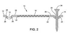
- FIG. 2is a cross-sectional view of the check strap along line 2 - 2 in FIG. 1 ;
- FIG. 3is a cross-sectional view of a door assembly including the check strap of FIG. 1 attached to a door hinge and extended to limit the opening movement of the door according to aspects of the present disclosure;
- FIG. 4is a cross-sectional view of the door assembly of FIG. 4 when the door is closed, further illustrating one example of a folded state of the check strap according to aspects of the present disclosure.
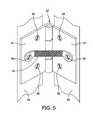
- FIG. 5is a perspective view of an exemplary embodiment of a door hinge assembly including a check strap according to aspects of the present disclosure.
- the check strap 10includes a first end portion 12 , and a second opposite end portion 14 .
- the check strap 10further includes a strip 16 disposed between the first end portion 12 and the second end portion 14 .
- the strip 16is fabricated from wire mesh fabric material to permit folding and to provide structural reinforcement.
- the strip 16may be fabricated from any other suitable material.
- Each of the first end portion 12 and the second end portion 14is made from a metal. However, each of the first end portion 12 and the second end portion 14 may be made from any other suitable material. As shown in FIG.
- the first end portion 12is in the form of an eyelet and includes a first opening 18 configured to receive a first attaching device.
- the second end portion 14is in the form of an eyelet and includes a second opening 20 configured to receive a second attaching device.
- each of the first and second attaching devicesmay be a screw.
- each of the openings 18 and 20may be circular, as shown in FIG. 1 .
- Each of the circular openings 18 and 20may have a diameter selected to limit translational movement of the first end portion 12 and the second end portion 14 upon attachment to respective surfaces, such as plates of a hinge, by their respective attaching devices.
- the openings 18 and 20may have other shapes configured to prevent translational movement of the first end portion 12 and the second end portion 14 .
- the first end portion 12may have a round shape including a flat portion with one end of the flat portion having a first edge 22 forming an interface with one end of the strip 16 , as shown in FIG. 1 , to connect the end of the strip to the first end portion.
- the second end portion 14may have a round shape including a flat portion, with one end of the flat portion having a second edge 24 forming an interface with an opposite end of the strip 16 , to connect the opposite end of the strip to the second end portion.
- first end portion 12 and the second end portion 14may have other shapes or distinct shapes, and may include a plurality of openings or slots.
- each of the first end portion 12 , the second end portion 14 and the strip 16may be made from a suitable metal.
- each of the first end portion 12 , the second end portion 14 and the strip 16may be made from any other suitable material.
- An interface between the strip 16 and each of the first end portion 12 and the second end portion 14 to securely affix the strip to the first end portionmay be constructed by applying any suitable method.
- the interfacesmay be constructed by one of crimping, welding, soldering and providing a unitary plastic.
- FIG. 2illustrates a cross-sectional view of the check strap 10 along line 2 - 2 in FIG. 1 .
- the first end portion 12has a flat surface portion 26 and a tapered edge portion 28 forming a dimple around the first opening 18 .
- the second end portion 14has a flat surface portion 30 and a tapered edge portion 32 forming a dimple around the second opening 20 .
- a screw 34is shown inserted through the second opening 20 of the second end portion 14 .
- the screw 34may be a standard wood screw used in conjunction with a standard hinge.
- the first opening 18 of the first end portion 12is also configured to receive a fastener (such as screw 36 shown in FIG. 3 ).
- FIG. 3illustrates the check strap 10 being attached to a hinge of a swinging door assembly, generally indicated at 37 .
- the door assembly 37includes a door 38 and a door jamb, generally indicated at 40 . Each end of the door jamb 40 may be disposed against a layer of sheetrock 42 as shown in FIG. 3 .
- the open space 44 and the one or more framing studs 46are contained between the layers of sheetrock 42 .
- the door assembly 37may also have a trim 48 .
- the door assembly 37includes a hinge generally indicated at 50 .
- the hinge 50includes a first plate 52 attached to the door 38 and a second plate 54 attached to the door jamb 40 .
- the hinge 50may be a standard hinge, and the plates 52 and 54 may be attached to the door 38 and the door jamb 40 , respectively, by standard screws, such as wood screws 34 and 36 shown in FIG. 3 .
- a check strap 10 made according to aspects disclosed hereinmay be attached to the hinge 50 using the same screws that attach plates 52 and 54 to the door 38 and the door jamb 40 , respectively.
- the first end portion 12 of the check strap 10is attached to the first plate 52 by the screw 36 , with the first plate being between the door 38 and the first end portion.
- the second end portion 14 of the check strap 10is attached to the second plate 54 by the screw 36 , with the second plate being between the door jamb 40 and the second end portion.
- the second screw 36extends at least partially through one of the framing studs 46 disposed behind the door jamb 40 and the open space 44 .
- each of the first end portion 12 and the second end portion 14 of the check strap 10may be attached respectively to the first plate 52 and the second plate 54 of the hinge 50 to prevent a translational movement of the first and second end portions with respect to the door 38 and the door jamb 40 , respectively.
- each of the end portions 12 and 14may be attached in an orientation selected to prevent twisting of the strip 16 .
- the end portions 12 and 14may have attachment locations having a same height on the first plate 52 and the second plate 54 .
- the attachment locationsmay be selected to be symmetrically positioned on the first plate 52 and the second plate 54 .
- the strip 16 of the check strap 10has a length selected to limit the outward or opening movement of the hinged door 38 when each of the first end portion 12 and the second end portion 14 is attached to a respective plate 52 , 54 of the hinge 50 .
- the length of the strip 16 of the check strap 10is selected to limit the opening of the door 38 to approximately 90 degrees. In another embodiment, the length of the strip 16 of the check strap 10 is selected to limit the opening of the door 38 to less than 90 degrees.
- the meshed or braided strip 16is configured to permit folding of the check strap 10 as the door 38 closes.
- FIG. 4shows the door assembly 37 of FIG. 3 with the door 38 being closed.
- the strip 16In the closed position, the first plate 52 and the second plate 54 are separated by a small distance.
- the strip 16is shown to be folded and disposed between the first plate 52 and the second plate 54 such that the strip is concealed between the plates when the door 38 is closed.
- the strip 16In the folded state, the strip 16 has a thickness that is less than the distance between the first plate 52 and the second plate 54 , thereby allowing the folded strip to fit between them.
- Rotational positions of each of the end portions 12 and 14 of the check strap 10may dictate the orientation of each of the edges 22 and 24 of the respective end portions, thereby guiding a direction of folding of the strip 16 upon closing door 38 .
- the strip 16may fold in different patterns.
- the strip 16may fold along a generally horizontal plane towards the intersection of the plates 52 and 54 as shown in FIG. 4 .
- the strip 16may fold along a generally horizontal plane in a direction away from the intersection of the plates 52 and 54 , or along a generally vertical plane that is parallel to the intersection of the plates 52 and 54 .
- the first end portion 12 and the second end portion 14each has a maximum thickness that fits within the distance between the plates 52 and 54 .
- the end portions 12 and 14are symmetrically positioned, a sum of their respective maximum thicknesses above the respective plates 52 and 54 is less than a distance between the first plate and the second plate in the closed position of the door.
- the end portionsmay have maximum thicknesses of approximately zero relative to the plates 52 , 54 in that the end portions are recessed within the plates.
- the methodincludes providing a check strap 10 having a first end portion 12 , a second end portion 14 and a strip 16 disposed between the first end portion and the second end portion as described herein; configuring the strip 16 to be fabricated from a meshed material to permit folding the strip while providing structural reinforcement; selecting a length of the strip 16 in a fully extended state so as to limit opening movement of the door 38 ; and selecting a thickness of a folded state of the strip 16 to be less than a distance between the first plate 52 and the second plate 54 in a closed position of the door 38 .
- the methodfurther includes attaching the first end portion 12 to the first plate 52 of the hinge 50 and attaching the second end portion 14 to the second plate 54 of the hinge; extending the strip 16 to the length to limit opening movement of the door 38 , and concealing the strip between the first plate 52 and the second plate 54 in the closed position of the door.
- the methodmay include concealing the strip between the door 38 and the door jamb 40 in the closed position of the door.
- the methodmay include removing screws 34 , 36 (for example, the offset middle screws associated with hinge 50 ), and securing the check strap 10 with the screws.
- screw 34may be longer than screw 36 so that the screw 34 reaches and bites into stud 46 .
- FIG. 5shows a perspective view of a door 38 and door jamb 40 coupled by a hinge 50 .
- Check strap 10is extended to limit the opening angle of the door 38 relative to the door jamb 40 .
- the hinge 50has a first plate 52 attached to the door 38 using a plurality of screws 56 .
- the hinge 50also has a second plate 54 attached to the door jamb 40 using a plurality of screws 58 .
- the screws 58include a middle screw which is offset relative to the other screws.
- one of the screws 58may be removed and replaced by a longer screw 34 , which is designed to screw into stud 46 (as shown in FIG. 4 ).
- the first end portion and the second end portion of the check strap 10are secured at the location of the offset middle screw 36 and the location of the offset middle screw 34 , respectively.
Landscapes
- Engineering & Computer Science (AREA)
- Mechanical Engineering (AREA)
- Hinges (AREA)
- Extensible Doors And Revolving Doors (AREA)
Abstract
Description
Claims (13)
Priority Applications (2)
| Application Number | Priority Date | Filing Date | Title |
|---|---|---|---|
| US13/404,472US8549711B2 (en) | 2012-02-24 | 2012-02-24 | Hinge mounted check strap and method of limiting opening movement of a hinged door |
| PCT/US2013/027224WO2013126631A1 (en) | 2012-02-24 | 2013-02-22 | Hinge mounted check strap and method of limiting opening movement of a hinged door |
Applications Claiming Priority (1)
| Application Number | Priority Date | Filing Date | Title |
|---|---|---|---|
| US13/404,472US8549711B2 (en) | 2012-02-24 | 2012-02-24 | Hinge mounted check strap and method of limiting opening movement of a hinged door |
Publications (2)
| Publication Number | Publication Date |
|---|---|
| US20130219665A1 US20130219665A1 (en) | 2013-08-29 |
| US8549711B2true US8549711B2 (en) | 2013-10-08 |
Family
ID=49001240
Family Applications (1)
| Application Number | Title | Priority Date | Filing Date |
|---|---|---|---|
| US13/404,472ActiveUS8549711B2 (en) | 2012-02-24 | 2012-02-24 | Hinge mounted check strap and method of limiting opening movement of a hinged door |
Country Status (2)
| Country | Link |
|---|---|
| US (1) | US8549711B2 (en) |
| WO (1) | WO2013126631A1 (en) |
Cited By (9)
| Publication number | Priority date | Publication date | Assignee | Title |
|---|---|---|---|---|
| US20140290005A1 (en)* | 2011-11-10 | 2014-10-02 | Hyundai Heavy Industries Co., Ltd. | Door hinge for heavy equipment |
| US9476238B2 (en)* | 2014-09-25 | 2016-10-25 | William Scott Mooers | Hinge providing an opening or closing force |
| US10240381B2 (en) | 2017-01-30 | 2019-03-26 | J. Theodore Brandley | Pipe and strap operating drive system for door mechanisms and similar structures |
| US10869457B1 (en)* | 2019-11-18 | 2020-12-22 | Ari M. Brandley | Ratcheted pipe and strap operating drive system for door mechanisms |
| US20220025684A1 (en)* | 2021-10-02 | 2022-01-27 | William Steven Kroll | Surface Mounted Door Check Device |
| US20220372806A1 (en)* | 2021-05-20 | 2022-11-24 | Summit Products, Inc. | Door stop system |
| US20230105723A1 (en)* | 2021-10-01 | 2023-04-06 | Michael A Papoulias | Door hinge limiter for automotive vehicle |
| US20240026717A1 (en)* | 2022-07-19 | 2024-01-25 | Textron Innovations Inc. | Stowable vehicle door securing system and apparatus |
| US20240328218A1 (en)* | 2023-03-31 | 2024-10-03 | Benito Moreno | Automotive Vehicle Door Restraint System |
Families Citing this family (1)
| Publication number | Priority date | Publication date | Assignee | Title |
|---|---|---|---|---|
| US9284763B2 (en)* | 2013-03-15 | 2016-03-15 | Jeffrey Lawrence Karcher | Door stop |
Citations (35)
| Publication number | Priority date | Publication date | Assignee | Title |
|---|---|---|---|---|
| US1472531A (en)* | 1922-05-27 | 1923-10-30 | Edward J Adams | Adjustable doorstop |
| US1481742A (en)* | 1921-05-06 | 1924-01-22 | Mahlon S Riley | Stop hinge |
| US1543912A (en)* | 1923-01-15 | 1925-06-30 | Goodrich Co B F | Doorcheck strap |
| US1607897A (en)* | 1925-02-07 | 1926-11-23 | John H Koons | Automobile door hinge |
| US1608554A (en) | 1924-12-06 | 1926-11-30 | Perfect Window Regulator Corp | Check strap for doors |
| US1646580A (en)* | 1926-04-23 | 1927-10-25 | Concealed Door Check Company | Doorcheck |
| US1757261A (en)* | 1929-01-10 | 1930-05-06 | Concealed Door Check Company | Doorcheck |
| US1757075A (en)* | 1929-08-06 | 1930-05-06 | Albert C Earhart | Door check or stop |
| US1775789A (en)* | 1929-11-18 | 1930-09-16 | Ideal Engineering Specialty Co | Doorcheck hinge |
| US1819212A (en)* | 1928-02-27 | 1931-08-18 | Hudson Motor Car Co | Doorstop strap |
| US1837517A (en) | 1930-01-13 | 1931-12-22 | Briggs Mfg Co | Check strap assembly |
| US2550626A (en)* | 1948-01-20 | 1951-04-24 | Benno M Vollmer | Adjustable door stay |
| US3157906A (en) | 1961-04-06 | 1964-11-24 | Wolf Emanuel | Door stop and closer |
| US3325854A (en) | 1964-09-25 | 1967-06-20 | Louis J Steigerwald | Door stop or door check |
| US3602942A (en) | 1969-09-26 | 1971-09-07 | Edsel B Neff Sr | Door hinge stop |
| US3913171A (en) | 1975-03-07 | 1975-10-21 | Ernest A Reid | Door hinge pin mounted adjustable door stop |
| US4070727A (en)* | 1976-06-29 | 1978-01-31 | Kazuyoshi Kanou | Device for automatic door closing |
| US4301570A (en)* | 1979-08-16 | 1981-11-24 | International Harvester Company | Door check and holding device for a motor vehicle |
| CH651887A5 (en)* | 1980-07-28 | 1985-10-15 | Steyr Daimler Puch Ag | Stop for vehicle doors |
| US4648152A (en) | 1983-03-18 | 1987-03-10 | Harpal Grewall | Retractable door stop |
| US4663801A (en)* | 1985-09-26 | 1987-05-12 | General Motors Corporation | Door check |
| DE3623603A1 (en)* | 1986-07-12 | 1988-01-14 | Robert Winkelstraeter Gmbh & C | Hinge |
| US4799721A (en)* | 1987-02-24 | 1989-01-24 | Amoco Corporation | Means to facilitate handling of core members and rolls of material |
| US5467507A (en) | 1993-09-17 | 1995-11-21 | Emhart Inc. | Polymer cable check strap |
| US6149212A (en) | 1997-07-02 | 2000-11-21 | Eagle Inventors, Llc | Adjustable door stop |
| US6220562B1 (en) | 1998-11-30 | 2001-04-24 | B. Walter & Co., Inc. | Furniture tipping restraint |
| US20010024591A1 (en) | 2000-03-09 | 2001-09-27 | Tokiwa Corporation | Cartridge type feeding container |
| US6311367B1 (en)* | 2000-03-22 | 2001-11-06 | Kenneth Duane Larsen | Apparatus and method for supporting a door in an open position |
| US6345416B1 (en)* | 1999-12-16 | 2002-02-12 | Kathleen M. Vollmar | Detachable, auxiliary car door handle |
| US6353967B1 (en) | 1998-09-02 | 2002-03-12 | Francisco A. Escobar | Ninety-degree door hinge |
| DE20118595U1 (en)* | 2001-11-16 | 2003-03-27 | Prämeta GmbH & Co. KG, 51107 Köln | Wardrobe door mortise hinge has plastic strap limiting door motion |
| GB2382105A (en) | 2001-11-14 | 2003-05-21 | Mark Robert Stolkin | Doorstop |
| US7559114B2 (en) | 2006-05-11 | 2009-07-14 | Anthony Ranilovich | Hinge attachable door stop insert |
| US20100269302A1 (en) | 2009-04-28 | 2010-10-28 | Govindarajan Jagannathan | Door hinge stop mechanism |
| US7904992B2 (en) | 2004-07-28 | 2011-03-15 | Vegas Doorstop Industries Inc. | Door stop |
Family Cites Families (1)
| Publication number | Priority date | Publication date | Assignee | Title |
|---|---|---|---|---|
| US8333359B2 (en)* | 2009-07-31 | 2012-12-18 | Randy Gordon | Jamb mounting bracket and method of use |
- 2012
- 2012-02-24USUS13/404,472patent/US8549711B2/enactiveActive
- 2013
- 2013-02-22WOPCT/US2013/027224patent/WO2013126631A1/enactiveApplication Filing
Patent Citations (35)
| Publication number | Priority date | Publication date | Assignee | Title |
|---|---|---|---|---|
| US1481742A (en)* | 1921-05-06 | 1924-01-22 | Mahlon S Riley | Stop hinge |
| US1472531A (en)* | 1922-05-27 | 1923-10-30 | Edward J Adams | Adjustable doorstop |
| US1543912A (en)* | 1923-01-15 | 1925-06-30 | Goodrich Co B F | Doorcheck strap |
| US1608554A (en) | 1924-12-06 | 1926-11-30 | Perfect Window Regulator Corp | Check strap for doors |
| US1607897A (en)* | 1925-02-07 | 1926-11-23 | John H Koons | Automobile door hinge |
| US1646580A (en)* | 1926-04-23 | 1927-10-25 | Concealed Door Check Company | Doorcheck |
| US1819212A (en)* | 1928-02-27 | 1931-08-18 | Hudson Motor Car Co | Doorstop strap |
| US1757261A (en)* | 1929-01-10 | 1930-05-06 | Concealed Door Check Company | Doorcheck |
| US1757075A (en)* | 1929-08-06 | 1930-05-06 | Albert C Earhart | Door check or stop |
| US1775789A (en)* | 1929-11-18 | 1930-09-16 | Ideal Engineering Specialty Co | Doorcheck hinge |
| US1837517A (en) | 1930-01-13 | 1931-12-22 | Briggs Mfg Co | Check strap assembly |
| US2550626A (en)* | 1948-01-20 | 1951-04-24 | Benno M Vollmer | Adjustable door stay |
| US3157906A (en) | 1961-04-06 | 1964-11-24 | Wolf Emanuel | Door stop and closer |
| US3325854A (en) | 1964-09-25 | 1967-06-20 | Louis J Steigerwald | Door stop or door check |
| US3602942A (en) | 1969-09-26 | 1971-09-07 | Edsel B Neff Sr | Door hinge stop |
| US3913171A (en) | 1975-03-07 | 1975-10-21 | Ernest A Reid | Door hinge pin mounted adjustable door stop |
| US4070727A (en)* | 1976-06-29 | 1978-01-31 | Kazuyoshi Kanou | Device for automatic door closing |
| US4301570A (en)* | 1979-08-16 | 1981-11-24 | International Harvester Company | Door check and holding device for a motor vehicle |
| CH651887A5 (en)* | 1980-07-28 | 1985-10-15 | Steyr Daimler Puch Ag | Stop for vehicle doors |
| US4648152A (en) | 1983-03-18 | 1987-03-10 | Harpal Grewall | Retractable door stop |
| US4663801A (en)* | 1985-09-26 | 1987-05-12 | General Motors Corporation | Door check |
| DE3623603A1 (en)* | 1986-07-12 | 1988-01-14 | Robert Winkelstraeter Gmbh & C | Hinge |
| US4799721A (en)* | 1987-02-24 | 1989-01-24 | Amoco Corporation | Means to facilitate handling of core members and rolls of material |
| US5467507A (en) | 1993-09-17 | 1995-11-21 | Emhart Inc. | Polymer cable check strap |
| US6149212A (en) | 1997-07-02 | 2000-11-21 | Eagle Inventors, Llc | Adjustable door stop |
| US6353967B1 (en) | 1998-09-02 | 2002-03-12 | Francisco A. Escobar | Ninety-degree door hinge |
| US6220562B1 (en) | 1998-11-30 | 2001-04-24 | B. Walter & Co., Inc. | Furniture tipping restraint |
| US6345416B1 (en)* | 1999-12-16 | 2002-02-12 | Kathleen M. Vollmar | Detachable, auxiliary car door handle |
| US20010024591A1 (en) | 2000-03-09 | 2001-09-27 | Tokiwa Corporation | Cartridge type feeding container |
| US6311367B1 (en)* | 2000-03-22 | 2001-11-06 | Kenneth Duane Larsen | Apparatus and method for supporting a door in an open position |
| GB2382105A (en) | 2001-11-14 | 2003-05-21 | Mark Robert Stolkin | Doorstop |
| DE20118595U1 (en)* | 2001-11-16 | 2003-03-27 | Prämeta GmbH & Co. KG, 51107 Köln | Wardrobe door mortise hinge has plastic strap limiting door motion |
| US7904992B2 (en) | 2004-07-28 | 2011-03-15 | Vegas Doorstop Industries Inc. | Door stop |
| US7559114B2 (en) | 2006-05-11 | 2009-07-14 | Anthony Ranilovich | Hinge attachable door stop insert |
| US20100269302A1 (en) | 2009-04-28 | 2010-10-28 | Govindarajan Jagannathan | Door hinge stop mechanism |
Non-Patent Citations (3)
| Title |
|---|
| Gregmporter, Karmann Ghia-Hinges and Check Straps. YouTube. Nov. 3, 2011 [retreived on May 7, 2013]. Retreived from the Internet: . |
| Gregmporter, Karmann Ghia—Hinges and Check Straps. YouTube. Nov. 3, 2011 [retreived on May 7, 2013]. Retreived from the Internet: <URL:http://www.youtube.com/watch?v=GizDG7zfuil>. |
| Notification of Transmittal of the International Search Report and the Written Opinion of the International Searching Authority from corresponding PCT/US2013/027224 mailed May 23, 2013. |
Cited By (16)
| Publication number | Priority date | Publication date | Assignee | Title |
|---|---|---|---|---|
| US20140290005A1 (en)* | 2011-11-10 | 2014-10-02 | Hyundai Heavy Industries Co., Ltd. | Door hinge for heavy equipment |
| US9169680B2 (en)* | 2011-11-10 | 2015-10-27 | Hyundai Heavy Industries Co., Ltd. | Door hinge for heavy equipment |
| US9476238B2 (en)* | 2014-09-25 | 2016-10-25 | William Scott Mooers | Hinge providing an opening or closing force |
| US10240381B2 (en) | 2017-01-30 | 2019-03-26 | J. Theodore Brandley | Pipe and strap operating drive system for door mechanisms and similar structures |
| US10869457B1 (en)* | 2019-11-18 | 2020-12-22 | Ari M. Brandley | Ratcheted pipe and strap operating drive system for door mechanisms |
| US11970892B2 (en)* | 2021-05-20 | 2024-04-30 | Summit Products, Inc. | Door stop system |
| US20220372806A1 (en)* | 2021-05-20 | 2022-11-24 | Summit Products, Inc. | Door stop system |
| US11905745B2 (en)* | 2021-10-01 | 2024-02-20 | Michael A Papoulias | Door hinge limiter for automotive vehicle |
| US11725435B2 (en)* | 2021-10-01 | 2023-08-15 | Michael A Papoulias | Door hinge limiter for automotive vehicle |
| US20230340814A1 (en)* | 2021-10-01 | 2023-10-26 | Michael A. Papoulias | Door hinge limiter for automotive vehicle |
| US20230105723A1 (en)* | 2021-10-01 | 2023-04-06 | Michael A Papoulias | Door hinge limiter for automotive vehicle |
| US11629535B2 (en)* | 2021-10-02 | 2023-04-18 | William Steven Kroll | Surface mounted door check device |
| US20220025684A1 (en)* | 2021-10-02 | 2022-01-27 | William Steven Kroll | Surface Mounted Door Check Device |
| US20240026717A1 (en)* | 2022-07-19 | 2024-01-25 | Textron Innovations Inc. | Stowable vehicle door securing system and apparatus |
| US12366097B2 (en)* | 2022-07-19 | 2025-07-22 | Textron Innovations Inc. | Stowable vehicle door securing system and apparatus |
| US20240328218A1 (en)* | 2023-03-31 | 2024-10-03 | Benito Moreno | Automotive Vehicle Door Restraint System |
Also Published As
| Publication number | Publication date |
|---|---|
| US20130219665A1 (en) | 2013-08-29 |
| WO2013126631A1 (en) | 2013-08-29 |
Similar Documents
| Publication | Publication Date | Title |
|---|---|---|
| US8549711B2 (en) | Hinge mounted check strap and method of limiting opening movement of a hinged door | |
| KR101558129B1 (en) | Door frame for sliding doors | |
| US9816303B2 (en) | Double axial hinge for a console | |
| US20140310915A1 (en) | Holding hinge assembly | |
| EP2801680B3 (en) | Device and kit for closing service boxes | |
| US20160194909A1 (en) | Door stop | |
| JP5586156B2 (en) | Door edge equipment | |
| CN216114948U (en) | Refrigerator with a door | |
| KR101771422B1 (en) | Handle for sliding door | |
| CN113445867B (en) | Hidden door and installation method thereof | |
| US9988832B2 (en) | Modular vehicle door | |
| JP6570560B2 (en) | Hinge | |
| CN108798324A (en) | Hinge means, installation method and refrigerator for refrigerator | |
| US9376846B2 (en) | Concealed hinge mechanism | |
| KR101189985B1 (en) | Frame assembly and the cabinet having the same | |
| CN108643775B (en) | Door opening limiting part | |
| CA2897661A1 (en) | Access door | |
| CA2793793A1 (en) | Access doors | |
| CN202090784U (en) | Cabinet door, cabinet door structure and file cabinet using the cabinet door structure | |
| JP6802007B2 (en) | Shielding structure for inward doors | |
| JP6955727B2 (en) | Folding door anti-vibration bracket | |
| US20020194703A1 (en) | Adjustable hinge | |
| CN215830351U (en) | Door frame structure with installation convenience | |
| JP2019148148A (en) | Indoor fitting | |
| JP7039338B2 (en) | Joinery |
Legal Events
| Date | Code | Title | Description |
|---|---|---|---|
| AS | Assignment | Owner name:TITUS, JAMES D., NEW HAMPSHIRE Free format text:ASSIGNMENT OF ASSIGNORS INTEREST;ASSIGNOR:APOSTOLOFF, DAVID;REEL/FRAME:027866/0686 Effective date:20120307 Owner name:APOSTOLOFF, DAVID, NEW HAMPSHIRE Free format text:ASSIGNMENT OF ASSIGNORS INTEREST;ASSIGNOR:APOSTOLOFF, DAVID;REEL/FRAME:027866/0686 Effective date:20120307 | |
| STCF | Information on status: patent grant | Free format text:PATENTED CASE | |
| REMI | Maintenance fee reminder mailed | ||
| FEPP | Fee payment procedure | Free format text:SURCHARGE FOR LATE PAYMENT, SMALL ENTITY (ORIGINAL EVENT CODE: M2554) | |
| MAFP | Maintenance fee payment | Free format text:PAYMENT OF MAINTENANCE FEE, 4TH YR, SMALL ENTITY (ORIGINAL EVENT CODE: M2551) Year of fee payment:4 | |
| FEPP | Fee payment procedure | Free format text:MAINTENANCE FEE REMINDER MAILED (ORIGINAL EVENT CODE: REM.); ENTITY STATUS OF PATENT OWNER: SMALL ENTITY | |
| FEPP | Fee payment procedure | Free format text:7.5 YR SURCHARGE - LATE PMT W/IN 6 MO, SMALL ENTITY (ORIGINAL EVENT CODE: M2555); ENTITY STATUS OF PATENT OWNER: SMALL ENTITY | |
| MAFP | Maintenance fee payment | Free format text:PAYMENT OF MAINTENANCE FEE, 8TH YR, SMALL ENTITY (ORIGINAL EVENT CODE: M2552); ENTITY STATUS OF PATENT OWNER: SMALL ENTITY Year of fee payment:8 | |
| MAFP | Maintenance fee payment | Free format text:PAYMENT OF MAINTENANCE FEE, 12TH YR, SMALL ENTITY (ORIGINAL EVENT CODE: M2553); ENTITY STATUS OF PATENT OWNER: SMALL ENTITY Year of fee payment:12 |