US8548181B2 - Inflatable ear mold connection system - Google Patents
Inflatable ear mold connection systemDownload PDFInfo
- Publication number
- US8548181B2 US8548181B2US13/702,665US201113702665AUS8548181B2US 8548181 B2US8548181 B2US 8548181B2US 201113702665 AUS201113702665 AUS 201113702665AUS 8548181 B2US8548181 B2US 8548181B2
- Authority
- US
- United States
- Prior art keywords
- balloon
- ear
- carrier
- ear piece
- receiver module
- Prior art date
- Legal status (The legal status is an assumption and is not a legal conclusion. Google has not performed a legal analysis and makes no representation as to the accuracy of the status listed.)
- Expired - Fee Related
Links
- 210000000613ear canalAnatomy0.000claimsabstractdescription14
- 210000003454tympanic membraneAnatomy0.000claimsabstractdescription12
- 238000003780insertionMethods0.000claimsabstractdescription5
- 230000037431insertionEffects0.000claimsabstractdescription4
- 239000012530fluidSubstances0.000claimsdescription10
- 238000007789sealingMethods0.000claimsdescription5
- 230000000149penetrating effectEffects0.000claimsdescription2
- 230000005236sound signalEffects0.000claims1
- 239000000463materialSubstances0.000description10
- 239000012528membraneSubstances0.000description4
- 238000009419refurbishmentMethods0.000description3
- 102100023170Nuclear receptor subfamily 1 group D member 1Human genes0.000description2
- 210000002939cerumenAnatomy0.000description2
- 238000010276constructionMethods0.000description2
- 229920001971elastomerPolymers0.000description2
- 238000004519manufacturing processMethods0.000description2
- 229920001296polysiloxanePolymers0.000description2
- 230000003068static effectEffects0.000description2
- XLYOFNOQVPJJNP-UHFFFAOYSA-NwaterSubstancesOXLYOFNOQVPJJNP-UHFFFAOYSA-N0.000description2
- 206010050337Cerumen impactionDiseases0.000description1
- 206010048865HypoacusisDiseases0.000description1
- 241000238367Mya arenariaSpecies0.000description1
- 210000000988bone and boneAnatomy0.000description1
- 210000004556brainAnatomy0.000description1
- 238000006243chemical reactionMethods0.000description1
- 235000012489doughnutsNutrition0.000description1
- 210000000883ear externalAnatomy0.000description1
- 230000000694effectsEffects0.000description1
- 239000013536elastomeric materialSubstances0.000description1
- 238000005516engineering processMethods0.000description1
- 229920001821foam rubberPolymers0.000description1
- 238000002347injectionMethods0.000description1
- 239000007924injectionSubstances0.000description1
- 239000004816latexSubstances0.000description1
- 229920000126latexPolymers0.000description1
- 239000007788liquidSubstances0.000description1
- 238000000034methodMethods0.000description1
- 238000012986modificationMethods0.000description1
- 230000004048modificationEffects0.000description1
- 230000000926neurological effectEffects0.000description1
- 238000005086pumpingMethods0.000description1
- 230000000717retained effectEffects0.000description1
- 239000007779soft materialSubstances0.000description1
Images


Classifications
- H—ELECTRICITY
- H04—ELECTRIC COMMUNICATION TECHNIQUE
- H04R—LOUDSPEAKERS, MICROPHONES, GRAMOPHONE PICK-UPS OR LIKE ACOUSTIC ELECTROMECHANICAL TRANSDUCERS; DEAF-AID SETS; PUBLIC ADDRESS SYSTEMS
- H04R25/00—Deaf-aid sets, i.e. electro-acoustic or electro-mechanical hearing aids; Electric tinnitus maskers providing an auditory perception
- H04R25/65—Housing parts, e.g. shells, tips or moulds, or their manufacture
- H04R25/652—Ear tips; Ear moulds
- H—ELECTRICITY
- H04—ELECTRIC COMMUNICATION TECHNIQUE
- H04R—LOUDSPEAKERS, MICROPHONES, GRAMOPHONE PICK-UPS OR LIKE ACOUSTIC ELECTROMECHANICAL TRANSDUCERS; DEAF-AID SETS; PUBLIC ADDRESS SYSTEMS
- H04R1/00—Details of transducers, loudspeakers or microphones
- H04R1/10—Earpieces; Attachments therefor ; Earphones; Monophonic headphones
- H04R1/1016—Earpieces of the intra-aural type
- H—ELECTRICITY
- H04—ELECTRIC COMMUNICATION TECHNIQUE
- H04R—LOUDSPEAKERS, MICROPHONES, GRAMOPHONE PICK-UPS OR LIKE ACOUSTIC ELECTROMECHANICAL TRANSDUCERS; DEAF-AID SETS; PUBLIC ADDRESS SYSTEMS
- H04R25/00—Deaf-aid sets, i.e. electro-acoustic or electro-mechanical hearing aids; Electric tinnitus maskers providing an auditory perception
- H04R25/65—Housing parts, e.g. shells, tips or moulds, or their manufacture
- H04R25/652—Ear tips; Ear moulds
- H04R25/656—Non-customized, universal ear tips, i.e. ear tips which are not specifically adapted to the size or shape of the ear or ear canal
Definitions
- the inventionrelates to an ear piece for a hearing device, in particular, an inflatable ear mold or an ear piece with an inflatable balloon.
- the ear pieceis particularly suitable for delivering sound from a hearing aid or an audio player.
- hearing aidsare wearable hearing apparatuses which are used to supply the hard-of-hearing.
- hearing devicessuch as, for example, behind-the-ear hearing devices (BTE), hearing device with an external receiver (RIC: receiver in the canal) and in-the-ear hearing devices (ITE), e.g. also concha hearing devices or canal hearing devices (ITE—in-the-ear, CIC—completely in the canal).
- BTEbehind-the-ear hearing devices
- RIChearing device with an external receiver
- ITEin-the-ear hearing devices
- ITEconcha hearing devices or canal hearing devices
- headphones for the personal delivery of auditory materialshave recently become more miniaturized and they have progressed to very small earbuds with in-the-canal speakers.
- a hearing devicePrimarily important components of a hearing device include an input converter (e.g., a microphone), an amplifier, and an output converter.
- an input convertere.g., a microphone
- an amplifiere.g., an MP3 player
- the signal originating from a memoryis amplified and fed to the output converter.
- the output converterin an electroacoustic converter (e.g., a miniature loudspeaker, bone conduction transducer) which converts the electrical signal into a mechanical vibration.
- the vibrationis converted to longitudinal pressure waves, also referred to as sound waves, which impinge on the tympanic membrane of the user. There, the sound waves are converted into neurological signals which are fed to the brain, where they are decoded for content.
- U.S. Pat. No. 7,227,968 B2describes a two-part hearing aid in which the receiver, which is separate from the remaining components, may be inserted deep into the auditory canal.
- the receiverhouses a speaker, which is driven by way of an electrical connection through the canal.
- the receiver housingis surrounded by an inflatable soft shell, which, when inflated and thus expanded, fixes the receiver in position in the auditory canal.
- U.S. Pat. No. 7,425,196 B2also describes a receiver module for a hearing aid that may be positioned deep in the auditory canal.
- the receiver housingis surrounded by an expandable material, which may be expanded against the walls of the canal.
- the insertion members of the ear pieceprefferably be replaced at certain intervals. Typically, only those parts which come into contact with the ear canal are replaced and the electronics (i.e., the receiver or receiver module) are returned into the canal. It is quite difficult and cumbersome to refurbish currently available state of the art devices and it is therefore desirable to render the refurbishment, and even the original assembly, less complicated and more efficient.
- the ear piecefurthermore, should be simple in its assembly and it should be modular for easy and simple refurbishment.
- an ear piece for a hearing devicewhich comprises:
- the inflatable ear mold(IEM) must be filled with a fluid (air or other gas, liquid) to assure the tight fit in the ear canal. Since the IEM must be replaceable, there is a need for a clever connection between the fluid source (e.g. a pump) and the IEM. Also, the handling and normal operation of such ear molds is a problem, because connecting two parts in a fluid-tight manner normally requires a special alignment of the two parts. This is even more critical at the very small dimensions which are of primary interest here.
- the receiver module of the canal-insertible ear moldhas width and height dimensions in the neighborhood of approximately 2-3 mm (approx. 0.08-0.1 inches)
- the instant inventionsolves these and other problems in an elegant manner by way of a providing an air-injection needle that projects centrally from the receiver module into the balloon carrier.
- radial projectionis an integral part of a bridge reaching across said axial bore and connecting to an inside wall of said carrier at diagonally opposed locations.
- the receiver modulecontains a sound source and wherein sound generated thereby is conducted through a forward wall of said receiver module, through said mount on said forward end thereof, and through said axial bore formed in said carrier.
- the receiver modulecontains a fluid source connected to said micro tube for selectively inflating said balloon.
- a fluidic connectionis automatically formed and sealed between said fluid source and an interior of said inflatable balloon when said receiver module is connected to said carrier.
- said fluid sourceis a pump assembly comprising an air pump for inflating said balloon and a deflation valve for deflating said balloon.
- said receiver moduleis mounted to project the sound waves through said mount and is connected by way of a signal line to a device for delivering electronic signals for processing in said receiver module.
- the signal lineincludes an electrical cable carrying electrical control signals and an energy supply.
- the mountis a snap-on bulb and said carrier is formed with substantially congruent opening, wherein said carrier may be snapped onto said mount, and said micro tube is formed with a hollow needle tip penetrating into said radial projection as said carrier is snapped onto said mount, for contemporaneously forming a pneumatic connection to the interior of said balloon.
- the inflatable ear piecemay be combined with any of a plurality of audiological devices, such as a hearing aid, an MP3 player, a cell phone, or any other such electronic device.
- the microphone, the amplifier, the control unit, and the power supplyis disposed in an external unit, such as a BTE (behind-the-ear) unit or an ITE (in-the-ear) unit, or in a CIC or concha device.
- the inflation pumpmay be disposed in/on the ear piece itself or in the external or partly inserted unit.
- the inflatable (deep-insertion) ear pieceis electrically connected to the other unit by way of an electrical control cable and, in one case, also through a pneumatic hose.
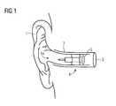
- FIG. 1is a schematic view of an outer ear with an auditory canal leading to an ear drum and an inflatable ear mold inserted into the canal;
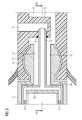
- FIG. 2is a longitudinal section taken through an ear piece according to the invention, formed of a receiver module and an inflatable balloon module;
- FIG. 3is an enlarged detail of FIG. 2 , illustrating the connection between the receiver module and the balloon module, the section taken along the line III-III in FIG. 4 ;
- FIG. 4is a view of the same detail, showing a longitudinal section taken along a plane IV-IV in FIG. 3 and rotated by 90 degrees relative to the section of FIG. 3 .
- FIG. 1there is seen a human ear 1 and an external auditory canal 2 .
- the auditory canalis inwardly bounded by a tympanic membrane 3 , also referred to as the eardrum.
- pressure wavessound waves are longitudinal waves with changes in pressure
- the ear canalalso referred to as the ear canal or, simply canal, before they impinge on the tympanic membrane 3 .
- the propagation of the sound waves through the auditory canal 2is interrupted.
- the sound wavesare instead picked up by a microphone or the like, the resulting signal is processed, typically by way of digital signal processing, and the processed signal is utilized to excite a loudspeaker, typically in the vicinity of or at the tympanic membrane 3 .
- the sound wavesare directly injected at the concha 1 a for delivery through the auditory canal 2 .
- the novel ear piece 4may include a sound generator (i.e., a speaker, oscillator) or it may be configured for simple conduction of sound waves to the membrane 3 .
- a receiver module 5has a height of approximately 2 mm and a width of approximately 2.7 mm.
- the acoustic sound channelhas an equivalent area of a circular cross-section of 1.2 mm and an air inflation channel has an equivalent circular cross-section of approximately 0.6 mm.
- a static airtight seal of the inflated balloonshould last for a minimum of 16 hours, which corresponds to a single-day use.
- the connection to the sound channeldoes not require a completely airtight seal, but a certain amount of seal should be provided so as to prevent acoustic feedback.
- an ear piece 4with the receiver module 5 , a carrier 6 , and an inflatable member 7 .
- the carrier 6 and the inflatable member 7together form an inflatable ear mold (IEM), or a balloon module.
- the carrier 6is formed of a relatively hard material and the inflatable member 7 is joined and fluid-tightly sealed to the carrier 6 .
- the latteris formed with a bulb opening which is congruent with a mount in the form of a snap-on dome 8 or a bulb 8 formed on the forward end of the receiver module 5 .
- the inflatable member 7may be in the form of a balloon or a bag or an accordion-type bellows, and may be simply referred to herein as a balloon 7 .
- the balloon 7is formed of a flexible material which is impermeable to cerumen, or earwax, and also to water.
- the balloon 7is preferably formed of silicone or latex, or any of the known flexible materials that are used for otoplastics and other cavity-insertible products known, especially, in the hearing aid arts. It may further be covered on the laterally outside walls, i.e., the walls that are braced into contact with the walls of the ear canal 2 , with a soft silicone or rubber material layer.
- the balloon 7resembles a tubeless tire, that is, it is sealed against the rim of the carrier 6 and, upon inflation, it forms a doughnut shaped thoroid fluid space.
- the fluid spacewhich is typically inflated with air, opens into a bore opening 9 formed in the carrier 6 .
- the bore opening 9is continued in a radial projection 10 , in the form of an appendix, that points radially inward into an axial opening 11 of the carrier 6 .
- the axial opening 11carries the sound waves from the receiver 5 to the ear drum 3 .
- the appendix 10forms only a minor obstruction inside the sound channel and does not have an appreciable effect on the sound conduction.
- the radial projection 10may also continue across the entire opening and thus form a bridge which may or may not issue into a second opening 9 across the illustrated opening.
- the receiver module 5carries a micro tube or needle 12 for the delivery of air to and from the air space inside the balloon 7 .
- the needle 12is mounted in the center of the bulb 8 and also centrally inside a sound tube 13 that projects axially through the bulb 8 .
- the needle 12is aligned so as to protrude into an opening 14 formed in a radial projection 10 , referred to as an appendix 10 , when the receiver module 5 and the balloon module 6 , 7 are connected to one another. That is, the opening 14 is located exactly centrally inside the assembly.
- the radial projection 10may also be formed as a (narrow) bridge extending entirely across the sound channel 11 and it may even be connected to a further inflation opening 9 formed diagonally across the illustrated opening 9 .
- the entire assemblyis rotationally symmetrical—with the exception, of course, of the appendix 10 —so that the balloon module 6 , 7 may be aligned in any rotational orientation relative to the receiver module 5 .
- Thisis highly advantageous when the two modules are connected to one another, be it in the original manufacture or when the balloon module is replaced by the audiologist or even be the user for refurbishment or retrofit. No rotational alignment of the parts is required.
- the needlewill always “find” the opening 14 and the needle 12 is assured to always penetrate and project into the opening 14 leading into the appendix 10 and opening into the inflation space inside the balloon 7 .
- a special seal between the needle 12 and the appendix 10there may be provided a special seal between the needle 12 and the appendix 10 .
- an O-ring 15 at the opening 14there is provided an O-ring 15 at the opening 14 .
- the sealing washer or membraneis formed of a suitable soft material, such as rubber or foam rubber, so that it seals around the needle and renders the connection between the pneumatic pumping system fluid-tight (i.e., gas tight and water tight).
- the basic concept of the inventionis not changed if the needle or microtube 12 forms a part of the balloon module and it is mounted centrally in the carrier 6 .
- a connection and a sealis provided at the receiver side, for example centrally in a forward wall 16 of the receiver module.
- the mount for the connection and the sealshould be formed so as not to appreciably obstruct the sound conduction from the receiver 5 through the sound channel 13 and the axial bore 11 .
- the receiver module 5contains the necessary electronics for generating a speaker signal for conversion to sound waves 8 at the forward end of the inflatable ear mold and for delivery to the tympanic membrane 3 . It is thereby possible for the speaker to be provided inside the receiver, or to be located externally of the receiver 5 . In one case, the receiver module 5 receives its information signal from an external assembly through a signal line 17 , which may also double as a pull-out tether for the IEM.
- the external assemblymay be a behind-the-ear (BTE) unit, a concha unit, an in-the-ear (ITE) unit, or even a completely-in-the-canal (CIC) hearing unit.
- BTEbehind-the-ear
- ITEin-the-ear
- CICcompletely-in-the-canal
- the ear piece 4 as described hereinmay be integrally formed together with a CIC unit. If the sound transducer is provided in an external unit, such as a BTE unit, the signal travels from there to the receiver in the form of a sound tube. That is, the diagrammatic illustration of the signal line 17 may also be understood as a sound tube.
- the signal line 17may be joined by a pneumatic pressure line 18 for inflating and deflating the balloon 7 .
- the pneumatic line 18is illustrated as a separate tube but it may be fully integrated with, and formed integrally in a one-piece construction with the line 17 .
- an inflation pump and a valvemay be provided in an external unit and the needle 12 is pneumatically connected with the pump/valve assembly through the line 18 .
- a pump/valve assembly 19is disposed inside the receiver module 5 .
- the pumpmay be an electrical pump or it may even be a manual pump.
- the useris enabled to inflate the IEM by suitable operation of a controller. Further, the user is also enabled to deflate the IEM so that the unit may be pulled from the auditory canal 2 .
- FIGS. 3 and 4show the same detail with sectional taken along planes that are perpendicular to one another. That is, FIG. 4 is a section that is taken along the line IV-IV in FIG. 3 , centrally along the longitudinal axis of the assembly and vertically into the paper plane.
- the section of FIG. 3cuts through the air flow duct 20 , which leads from the pump/valve assembly 21 into the micro tube or needle 12 , and also through the radial projection 10 .
- the air flow duct 20obstructs the sound channel 13 leading from the receiver module 5 and through the connector bulb 8 only to a minor degree.
- the radial projection 10covers only a minor portion of the flow cross section inside the sound channel 11 .
Landscapes
- Engineering & Computer Science (AREA)
- Physics & Mathematics (AREA)
- Acoustics & Sound (AREA)
- Signal Processing (AREA)
- Manufacturing & Machinery (AREA)
- Health & Medical Sciences (AREA)
- General Health & Medical Sciences (AREA)
- Neurosurgery (AREA)
- Otolaryngology (AREA)
- Headphones And Earphones (AREA)
- Percussion Or Vibration Massage (AREA)
Abstract
Description
- an inflatable ear mold (IEM) for insertion and placement in an ear canal, said inflatable ear mold (IEM) having a carrier and an inflatable balloon sealingly mounted on said carrier;
- a receiver module having a mount on a forward end thereof for connecting said receiver module to said carrier and said balloon;
- said carrier having an axial bore formed along a central axis thereof, said bore forming a sound channel for conducting sound from said receiver module towards an ear drum inwardly bounding the ear canal;
- a radial projection formed on a wall of said axial bore and jutting at least into a center of said axial bore and intersecting said central axis, said radial projection having an opening aligned with the central axis of said axial bore, said radial projection having a bore formed therein fluidically connecting an interior inflation space of said balloon with said opening;
- a micro tube projecting centrally into said axial bore when said receiver and said carrier are connected, and projecting into and sealing against said opening in said radial projection, for enabling said balloon to be inflated, and optionally deflated, through said micro tube.
Claims (15)
Priority Applications (1)
| Application Number | Priority Date | Filing Date | Title |
|---|---|---|---|
| US13/702,665US8548181B2 (en) | 2010-07-13 | 2011-07-13 | Inflatable ear mold connection system |
Applications Claiming Priority (4)
| Application Number | Priority Date | Filing Date | Title |
|---|---|---|---|
| US36381410P | 2010-07-13 | 2010-07-13 | |
| US38563510P | 2010-09-23 | 2010-09-23 | |
| PCT/EP2011/061962WO2012007508A2 (en) | 2010-07-13 | 2011-07-13 | Inflatable ear mold connection system |
| US13/702,665US8548181B2 (en) | 2010-07-13 | 2011-07-13 | Inflatable ear mold connection system |
Publications (2)
| Publication Number | Publication Date |
|---|---|
| US20130101147A1 US20130101147A1 (en) | 2013-04-25 |
| US8548181B2true US8548181B2 (en) | 2013-10-01 |
Family
ID=44169197
Family Applications (3)
| Application Number | Title | Priority Date | Filing Date |
|---|---|---|---|
| US13/809,793Expired - Fee RelatedUS8903113B2 (en) | 2010-07-13 | 2011-04-08 | Inflatable ear mold with protected inflation air inlet |
| US13/702,665Expired - Fee RelatedUS8548181B2 (en) | 2010-07-13 | 2011-07-13 | Inflatable ear mold connection system |
| US14/444,223Expired - Fee RelatedUS9226086B2 (en) | 2010-07-13 | 2014-07-28 | Inflatable ear mold with protected inflation air inlet |
Family Applications Before (1)
| Application Number | Title | Priority Date | Filing Date |
|---|---|---|---|
| US13/809,793Expired - Fee RelatedUS8903113B2 (en) | 2010-07-13 | 2011-04-08 | Inflatable ear mold with protected inflation air inlet |
Family Applications After (1)
| Application Number | Title | Priority Date | Filing Date |
|---|---|---|---|
| US14/444,223Expired - Fee RelatedUS9226086B2 (en) | 2010-07-13 | 2014-07-28 | Inflatable ear mold with protected inflation air inlet |
Country Status (5)
| Country | Link |
|---|---|
| US (3) | US8903113B2 (en) |
| EP (2) | EP2594086A1 (en) |
| CN (1) | CN102972044B (en) |
| DK (1) | DK2594091T3 (en) |
| WO (2) | WO2012007193A1 (en) |
Cited By (18)
| Publication number | Priority date | Publication date | Assignee | Title |
|---|---|---|---|---|
| US20130136285A1 (en)* | 2010-07-13 | 2013-05-30 | Siemens Medical Instruments Pte. Ltd. | Inflatable ear piece with pressure relief valve |
| US20140166122A1 (en)* | 2007-07-09 | 2014-06-19 | Personics Holdings Inc. | Methods and mechanisms for inflation |
| US20150264468A1 (en)* | 2014-02-14 | 2015-09-17 | Sonion Nederland B.V. | Joiner For A Receiver Assembly |
| US9167328B2 (en) | 2013-02-28 | 2015-10-20 | Sivantos Pte. Ltd. | Valve apparatus, hearing device with the valve apparatus, and method |
| US20160050483A1 (en)* | 2014-08-15 | 2016-02-18 | Voyetra Turtle Beach, Inc. | Earphones with motion sensitive inflation |
| US10110988B2 (en) | 2016-04-19 | 2018-10-23 | Christopher Robert Barry | Human-ear-wearable apparatus, system, and method of operation |
| WO2019031985A1 (en)* | 2017-08-08 | 2019-02-14 | Михаил Викторович КУЧЕРЕНКО | In-canal earphone |
| US10506320B1 (en)* | 2019-01-10 | 2019-12-10 | Phillip Dale Lott | Dynamic earphone tip |
| US10897678B2 (en) | 2008-10-15 | 2021-01-19 | Staton Techiya, Llc | Device and method to reduce ear wax clogging of acoustic ports, hearing aid sealing system, and feedback reduction system |
| US20210377643A1 (en)* | 2018-12-14 | 2021-12-02 | Sony Group Corporation | Sound device and sound system |
| US11310580B2 (en)* | 2011-06-01 | 2022-04-19 | Staton Techiya, Llc | Methods and devices for radio frequency (RF) mitigation proximate the ear |
| US11430422B2 (en)* | 2015-05-29 | 2022-08-30 | Staton Techiya Llc | Methods and devices for attenuating sound in a conduit or chamber |
| US11496823B2 (en)* | 2018-04-25 | 2022-11-08 | Sekisui Polymatech Co., Ltd. | Earpiece |
| US12183341B2 (en) | 2008-09-22 | 2024-12-31 | St Casestech, Llc | Personalized sound management and method |
| US12193841B2 (en) | 2014-12-10 | 2025-01-14 | The Diablo Canyon Collective Llc | Sensor control of an audio device |
| US12249326B2 (en) | 2007-04-13 | 2025-03-11 | St Case1Tech, Llc | Method and device for voice operated control |
| US12256188B2 (en) | 2018-03-09 | 2025-03-18 | Earsoft, Llc | Eartips and earphone devices, and systems and methods therefore |
| US12289576B2 (en) | 2007-07-12 | 2025-04-29 | St Tiptech, Llc | Expandable sealing devices and methods |
Families Citing this family (33)
| Publication number | Priority date | Publication date | Assignee | Title |
|---|---|---|---|---|
| EP2598215A4 (en)* | 2010-07-28 | 2014-01-29 | Sunbeam Products Inc | Pelvic muscle trainer |
| US9288592B2 (en)* | 2012-02-02 | 2016-03-15 | Conversion Sound Inc. | Custom ear adaptor system with balloon-style or elastomeric dome earpiece |
| US9380379B1 (en)* | 2012-03-14 | 2016-06-28 | Google Inc. | Bone-conduction anvil and diaphragm |
| US20130251172A1 (en)* | 2012-03-21 | 2013-09-26 | Jack Mosseri | Inflatable Ear Buds |
| KR20140002816A (en)* | 2012-06-25 | 2014-01-09 | 한국전자통신연구원 | Apparatus and method for transmitting acoustic signal using human body |
| DE102012217844A1 (en)* | 2012-07-06 | 2014-01-09 | Siemens Medical Instruments Pte. Ltd. | Pumping device for hearing aid |
| DE102012214976B3 (en)* | 2012-08-23 | 2013-11-07 | Siemens Medical Instruments Pte. Ltd. | Hearing instrument and earpiece with receiver |
| DE102012221233A1 (en)* | 2012-09-12 | 2014-03-13 | Siemens Medical Instruments Pte. Ltd. | Coupling hearing device for a hearing device |
| US20140119586A1 (en)* | 2012-10-25 | 2014-05-01 | Sonion A/S | Hearing aid assembly |
| US20140205123A1 (en)* | 2013-01-23 | 2014-07-24 | Sonion Nederland B.V. | Balloon connector for a hearing aid assembly |
| EP2819435A1 (en)* | 2013-06-26 | 2014-12-31 | Oticon A/s | Vented dome |
| US10251790B2 (en) | 2013-06-28 | 2019-04-09 | Nocira, Llc | Method for external ear canal pressure regulation to alleviate disorder symptoms |
| US12396892B2 (en) | 2013-06-28 | 2025-08-26 | Nocira, Llc | External ear canal pressure regulation device |
| US9039639B2 (en) | 2013-06-28 | 2015-05-26 | Gbs Ventures Llc | External ear canal pressure regulation system |
| CN104473719A (en)* | 2014-12-08 | 2015-04-01 | 上海斐讯数据通信技术有限公司 | Earplug |
| DK3116238T3 (en)* | 2015-07-08 | 2020-03-23 | Oticon As | SPACES AND HEARING DEVICE INCLUDING IT |
| US10045107B2 (en)* | 2015-07-21 | 2018-08-07 | Harman International Industries, Incorporated | Eartip that conforms to a user's ear canal |
| US11457323B2 (en) | 2016-04-26 | 2022-09-27 | Gn Hearing A/S | Custom elastomeric earmold with secondary material infusion |
| CN105979427A (en)* | 2016-07-19 | 2016-09-28 | 华峰君 | Energy-saving smart earphone |
| US10760566B2 (en) | 2016-07-22 | 2020-09-01 | Nocira, Llc | Magnetically driven pressure generator |
| EP3334179B1 (en)* | 2016-12-12 | 2021-10-13 | Oticon A/s | Hearing aid with an extended dome |
| EP4424293A3 (en) | 2017-02-27 | 2024-11-27 | Nocira, LLC | Ear pumps |
| CN108324426B (en)* | 2018-03-26 | 2019-10-18 | 桂林市兴达光电医疗器械有限公司 | A kind of ear protection device |
| EP3810049A4 (en) | 2018-06-22 | 2022-03-23 | Nocira, LLC | Systems and methods for treating neurological disorders |
| US20200078509A1 (en)* | 2018-09-12 | 2020-03-12 | Xinova, LLC | Micro-dispenser based ear treatment |
| US11418865B2 (en)* | 2018-12-07 | 2022-08-16 | Gn Hearing A/S | Configurable hearing devices |
| CN111065028A (en)* | 2019-12-27 | 2020-04-24 | 歌尔股份有限公司 | Vibrating diaphragm ball top, vibrating diaphragm and loudspeaker |
| CN111491246B (en)* | 2020-04-24 | 2021-07-27 | 朱海涛 | Multifunctional hearing aid |
| CN114554336A (en)* | 2020-11-25 | 2022-05-27 | 深圳富泰宏精密工业有限公司 | Earphone set |
| CN112788462B (en)* | 2021-01-14 | 2022-08-26 | 深圳市弘毅佳科技有限公司 | In-ear earphone capable of avoiding ear ache |
| CN113271528B (en)* | 2021-07-19 | 2021-11-19 | 西安交通大学医学院第二附属医院 | Medical audiphone suitable for otolaryngology branch of academic or vocational study |
| CN113794977B (en)* | 2021-09-28 | 2024-04-05 | 武汉左点科技有限公司 | Quick self-adaptive adjusting method and device for hearing aid system |
| US12418759B2 (en) | 2023-03-20 | 2025-09-16 | Sonova Ag | Hearing device having a shell that includes a compressible region and methods of manufacturing the same |
Citations (6)
| Publication number | Priority date | Publication date | Assignee | Title |
|---|---|---|---|---|
| US20020196958A1 (en) | 2001-06-25 | 2002-12-26 | Halteren Aart Zeger Van | Expansible receiver module |
| US7425196B2 (en) | 2002-12-23 | 2008-09-16 | Sonion Roskilde A/S | Balloon encapsulated direct drive |
| US20100002897A1 (en) | 2008-07-06 | 2010-01-07 | Personics Holdings Inc. | Pressure regulating systems for expandable insertion devices |
| WO2010132359A2 (en) | 2009-05-09 | 2010-11-18 | Asius Technologies, Llc | Inflatable ear device |
| US20100322454A1 (en) | 2008-07-23 | 2010-12-23 | Asius Technologies, Llc | Inflatable Ear Device |
| US20110079227A1 (en) | 2009-10-05 | 2011-04-07 | Turcot Michael C | Pressure regulation mechanism for inflatable in-ear device |
Family Cites Families (6)
| Publication number | Priority date | Publication date | Assignee | Title |
|---|---|---|---|---|
| JPS5330316A (en) | 1976-09-01 | 1978-03-22 | Koken Kk | Sealed sound receiver |
| US4834211A (en)* | 1988-02-02 | 1989-05-30 | Kenneth Bibby | Anchoring element for in-the-ear devices |
| CN101098566A (en)* | 2006-06-30 | 2008-01-02 | 陈浩 | Gas-controlled compact earphone |
| KR100859979B1 (en)* | 2007-07-20 | 2008-09-25 | 경북대학교 산학협력단 | Artificial ear of the garden drive method by tube vibration transducer |
| US8340310B2 (en)* | 2007-07-23 | 2012-12-25 | Asius Technologies, Llc | Diaphonic acoustic transduction coupler and ear bud |
| US9539147B2 (en) | 2009-02-13 | 2017-01-10 | Personics Holdings, Llc | Method and device for acoustic sealing and occlusion effect mitigation |
- 2011
- 2011-04-08USUS13/809,793patent/US8903113B2/ennot_activeExpired - Fee Related
- 2011-04-08WOPCT/EP2011/055520patent/WO2012007193A1/enactiveApplication Filing
- 2011-04-08CNCN201180033433.1Apatent/CN102972044B/ennot_activeExpired - Fee Related
- 2011-04-08EPEP11714736.3Apatent/EP2594086A1/ennot_activeWithdrawn
- 2011-07-13WOPCT/EP2011/061962patent/WO2012007508A2/enactiveApplication Filing
- 2011-07-13DKDK11732446.7Tpatent/DK2594091T3/enactive
- 2011-07-13USUS13/702,665patent/US8548181B2/ennot_activeExpired - Fee Related
- 2011-07-13EPEP11732446.7Apatent/EP2594091B1/ennot_activeNot-in-force
- 2014
- 2014-07-28USUS14/444,223patent/US9226086B2/ennot_activeExpired - Fee Related
Patent Citations (8)
| Publication number | Priority date | Publication date | Assignee | Title |
|---|---|---|---|---|
| US20020196958A1 (en) | 2001-06-25 | 2002-12-26 | Halteren Aart Zeger Van | Expansible receiver module |
| EP1272003A1 (en) | 2001-06-25 | 2003-01-02 | SonionMicrotronic A/S | An expansible receiver module |
| US7227968B2 (en) | 2001-06-25 | 2007-06-05 | Sonion Roskilde A/S | Expandsible Receiver Module |
| US7425196B2 (en) | 2002-12-23 | 2008-09-16 | Sonion Roskilde A/S | Balloon encapsulated direct drive |
| US20100002897A1 (en) | 2008-07-06 | 2010-01-07 | Personics Holdings Inc. | Pressure regulating systems for expandable insertion devices |
| US20100322454A1 (en) | 2008-07-23 | 2010-12-23 | Asius Technologies, Llc | Inflatable Ear Device |
| WO2010132359A2 (en) | 2009-05-09 | 2010-11-18 | Asius Technologies, Llc | Inflatable ear device |
| US20110079227A1 (en) | 2009-10-05 | 2011-04-07 | Turcot Michael C | Pressure regulation mechanism for inflatable in-ear device |
Cited By (39)
| Publication number | Priority date | Publication date | Assignee | Title |
|---|---|---|---|---|
| US12249326B2 (en) | 2007-04-13 | 2025-03-11 | St Case1Tech, Llc | Method and device for voice operated control |
| US10009677B2 (en)* | 2007-07-09 | 2018-06-26 | Staton Techiya, Llc | Methods and mechanisms for inflation |
| US20140166122A1 (en)* | 2007-07-09 | 2014-06-19 | Personics Holdings Inc. | Methods and mechanisms for inflation |
| US12289576B2 (en) | 2007-07-12 | 2025-04-29 | St Tiptech, Llc | Expandable sealing devices and methods |
| US12183341B2 (en) | 2008-09-22 | 2024-12-31 | St Casestech, Llc | Personalized sound management and method |
| US12374332B2 (en) | 2008-09-22 | 2025-07-29 | ST Fam Tech, LLC | Personalized sound management and method |
| US11638109B2 (en) | 2008-10-15 | 2023-04-25 | Staton Techiya, Llc | Device and method to reduce ear wax clogging of acoustic ports, hearing aid sealing system, and feedback reduction system |
| US10979831B2 (en) | 2008-10-15 | 2021-04-13 | Staton Techiya, Llc | Device and method to reduce ear wax clogging of acoustic ports, hearing aid sealing system, and feedback reduction system |
| US10897678B2 (en) | 2008-10-15 | 2021-01-19 | Staton Techiya, Llc | Device and method to reduce ear wax clogging of acoustic ports, hearing aid sealing system, and feedback reduction system |
| US12212936B2 (en) | 2008-10-15 | 2025-01-28 | The Diablo Canyon Collective Llc | Device and method to reduce ear wax clogging of acoustic ports, hearing aid sealing system, and feedback reduction system |
| US11223918B2 (en) | 2008-10-15 | 2022-01-11 | Staton Techiya, Llc | Device and method to reduce ear wax clogging of acoustic ports, hearing aid sealing system, and feedback reduction system |
| US11956600B2 (en) | 2008-10-15 | 2024-04-09 | The Diablo Canyon Collective Llc | Device and method to reduce ear wax clogging of acoustic ports, hearing aid sealing system, and feedback reduction system |
| US11700495B2 (en) | 2008-10-15 | 2023-07-11 | Staton Techiya Llc | Device and method to reduce ear wax clogging of acoustic ports, hearing aid sealing system, and feedback reduction system |
| US20130136285A1 (en)* | 2010-07-13 | 2013-05-30 | Siemens Medical Instruments Pte. Ltd. | Inflatable ear piece with pressure relief valve |
| US11310580B2 (en)* | 2011-06-01 | 2022-04-19 | Staton Techiya, Llc | Methods and devices for radio frequency (RF) mitigation proximate the ear |
| US10200775B2 (en) | 2012-12-17 | 2019-02-05 | Staton Techiya, Llc | Methods and mechanisms for inflation |
| US11006199B2 (en) | 2012-12-17 | 2021-05-11 | Staton Techiya, Llc | Methods and mechanisms for inflation |
| US11659315B2 (en) | 2012-12-17 | 2023-05-23 | Staton Techiya Llc | Methods and mechanisms for inflation |
| US9167328B2 (en) | 2013-02-28 | 2015-10-20 | Sivantos Pte. Ltd. | Valve apparatus, hearing device with the valve apparatus, and method |
| US9584898B2 (en)* | 2014-02-14 | 2017-02-28 | Sonion Nederland B.V. | Joiner for a receiver assembly |
| US20150264468A1 (en)* | 2014-02-14 | 2015-09-17 | Sonion Nederland B.V. | Joiner For A Receiver Assembly |
| US10194230B2 (en)* | 2014-08-15 | 2019-01-29 | Voyetra Turtle Beach, Inc. | Earphones with motion sensitive inflation |
| US11937038B2 (en) | 2014-08-15 | 2024-03-19 | Voyetra Turtle Beach, Inc | Earphones with motion sensitive inflation |
| US20160050483A1 (en)* | 2014-08-15 | 2016-02-18 | Voyetra Turtle Beach, Inc. | Earphones with motion sensitive inflation |
| US11223893B2 (en) | 2014-08-15 | 2022-01-11 | Voyetra Turtle Beach, Inc. | Audio output devices with user-based adjustable contact components |
| US12193841B2 (en) | 2014-12-10 | 2025-01-14 | The Diablo Canyon Collective Llc | Sensor control of an audio device |
| US11430422B2 (en)* | 2015-05-29 | 2022-08-30 | Staton Techiya Llc | Methods and devices for attenuating sound in a conduit or chamber |
| US11727910B2 (en) | 2015-05-29 | 2023-08-15 | Staton Techiya Llc | Methods and devices for attenuating sound in a conduit or chamber |
| US10110988B2 (en) | 2016-04-19 | 2018-10-23 | Christopher Robert Barry | Human-ear-wearable apparatus, system, and method of operation |
| US10129634B2 (en) | 2016-04-19 | 2018-11-13 | Christopher Robert Barry | Human-ear-wearable apparatus, system, and method of operation |
| WO2019031985A1 (en)* | 2017-08-08 | 2019-02-14 | Михаил Викторович КУЧЕРЕНКО | In-canal earphone |
| RU2680663C2 (en)* | 2017-08-08 | 2019-02-25 | Михаил Викторович Кучеренко | In-ear headphone |
| US12256188B2 (en) | 2018-03-09 | 2025-03-18 | Earsoft, Llc | Eartips and earphone devices, and systems and methods therefore |
| US11496823B2 (en)* | 2018-04-25 | 2022-11-08 | Sekisui Polymatech Co., Ltd. | Earpiece |
| US11743626B2 (en)* | 2018-12-14 | 2023-08-29 | Sony Group Corporation | Sound device and sound system |
| US20210377643A1 (en)* | 2018-12-14 | 2021-12-02 | Sony Group Corporation | Sound device and sound system |
| US10506320B1 (en)* | 2019-01-10 | 2019-12-10 | Phillip Dale Lott | Dynamic earphone tip |
| US20200228889A1 (en)* | 2019-01-10 | 2020-07-16 | Phillip Dale Lott | Dynamic earphone tip |
| US11006198B2 (en) | 2019-01-10 | 2021-05-11 | Phillip Dale Lott | Dynamic earphone tip |
Also Published As
| Publication number | Publication date |
|---|---|
| US8903113B2 (en) | 2014-12-02 |
| EP2594091A2 (en) | 2013-05-22 |
| US20140334652A1 (en) | 2014-11-13 |
| WO2012007508A2 (en) | 2012-01-19 |
| EP2594091B1 (en) | 2014-06-04 |
| DK2594091T3 (en) | 2014-09-15 |
| WO2012007193A1 (en) | 2012-01-19 |
| US9226086B2 (en) | 2015-12-29 |
| WO2012007508A3 (en) | 2013-03-28 |
| CN102972044B (en) | 2016-03-16 |
| US20130101147A1 (en) | 2013-04-25 |
| EP2594086A1 (en) | 2013-05-22 |
| CN102972044A (en) | 2013-03-13 |
| US20130114839A1 (en) | 2013-05-09 |
Similar Documents
| Publication | Publication Date | Title |
|---|---|---|
| US8548181B2 (en) | Inflatable ear mold connection system | |
| EP2594085B1 (en) | Inflatable ear piece with pressure relief valve | |
| EP1272003B1 (en) | An expansible receiver module | |
| EP1434464B1 (en) | Encapsulated receiver comprising an expansible means such as a balloon | |
| US8526651B2 (en) | Receiver module for inflating a membrane in an ear device | |
| US8312960B2 (en) | Occlusion effect mitigation and sound isolation device for orifice inserted systems | |
| US9154892B2 (en) | Hearing instrument with a balloon and a separate sound channel and air supply channel | |
| US9025807B2 (en) | Couplable hearing apparatus for a hearing device, coupling element and hearing device | |
| KR20120068767A (en) | Inflatable ear device | |
| WO2012113462A1 (en) | Inflatable ear mold connection system | |
| WO2012076061A1 (en) | Inflatable ear mold connection system | |
| CN116896701A (en) | Hearing device | |
| US10327055B2 (en) | Closed acoustical architecture having a controlled leakage | |
| WO2012007187A2 (en) | Inflatable ear mold interface connection system | |
| CN116896702A (en) | hearing device | |
| CN116896700A (en) | hearing equipment | |
| CN114584881A (en) | Earphone and mobile terminal |
Legal Events
| Date | Code | Title | Description |
|---|---|---|---|
| FEPP | Fee payment procedure | Free format text:PAYOR NUMBER ASSIGNED (ORIGINAL EVENT CODE: ASPN); ENTITY STATUS OF PATENT OWNER: LARGE ENTITY | |
| AS | Assignment | Owner name:SIEMENS MEDICAL INSTRUMENTS PTE.LTD., SINGAPORE Free format text:ASSIGNMENT OF ASSIGNORS INTEREST;ASSIGNORS:KRAEMER, WOLFGANG;SIEMENS AUDIOLOGISCHE TECHNIK GMBH;SIGNING DATES FROM 20121126 TO 20121130;REEL/FRAME:029470/0546 | |
| AS | Assignment | Owner name:SIEMENS AUDIOLOGISCHE TECHNIK GMBH, GERMANY Free format text:CORRECTIVE ASSIGNMENT TO CORRECT THE ASSIGNEE AND ASSIGNOR INFORMATION INCORRECTLY LISTED PREVIOUSLY RECORDED ON REEL 029470 FRAME 0546. ASSIGNOR(S) HEREBY CONFIRMS THE CORRECT ASSIGNOR IS WOLFGANG KRAEMER AND THE CORRECT ASSIGNEE IS SIEMENS AUDIOLOGISCHE TECHNIK GMBH;ASSIGNOR:KRAEMER, WOLFGANG;REEL/FRAME:029572/0407 Effective date:20121126 | |
| AS | Assignment | Owner name:SIEMENS MEDICAL INSTRUMENTS PTE. LTD., SINGAPORE Free format text:ASSIGNMENT OF ASSIGNORS INTEREST;ASSIGNOR:SIEMENS AUDIOLOGISCHE TECHNIK GMBH;REEL/FRAME:029584/0017 Effective date:20121130 | |
| STCF | Information on status: patent grant | Free format text:PATENTED CASE | |
| AS | Assignment | Owner name:SIVANTOS PTE. LTD., SINGAPORE Free format text:CHANGE OF NAME;ASSIGNOR:SIEMENS MEDICAL INSTRUMENTS PTE. LTD.;REEL/FRAME:036089/0827 Effective date:20150416 | |
| FPAY | Fee payment | Year of fee payment:4 | |
| FEPP | Fee payment procedure | Free format text:MAINTENANCE FEE REMINDER MAILED (ORIGINAL EVENT CODE: REM.); ENTITY STATUS OF PATENT OWNER: LARGE ENTITY | |
| LAPS | Lapse for failure to pay maintenance fees | Free format text:PATENT EXPIRED FOR FAILURE TO PAY MAINTENANCE FEES (ORIGINAL EVENT CODE: EXP.); ENTITY STATUS OF PATENT OWNER: LARGE ENTITY | |
| STCH | Information on status: patent discontinuation | Free format text:PATENT EXPIRED DUE TO NONPAYMENT OF MAINTENANCE FEES UNDER 37 CFR 1.362 | |
| FP | Lapsed due to failure to pay maintenance fee | Effective date:20211001 |