US8547657B1 - Disk drive detecting defective microactuator - Google Patents
Disk drive detecting defective microactuatorDownload PDFInfo
- Publication number
- US8547657B1 US8547657B1US12/797,883US79788310AUS8547657B1US 8547657 B1US8547657 B1US 8547657B1US 79788310 AUS79788310 AUS 79788310AUS 8547657 B1US8547657 B1US 8547657B1
- Authority
- US
- United States
- Prior art keywords
- microactuator
- recited
- head
- servo
- disk drive
- Prior art date
- Legal status (The legal status is an assumption and is not a legal conclusion. Google has not performed a legal analysis and makes no representation as to the accuracy of the status listed.)
- Expired - Fee Related, expires
Links
Images


Classifications
- G—PHYSICS
- G11—INFORMATION STORAGE
- G11B—INFORMATION STORAGE BASED ON RELATIVE MOVEMENT BETWEEN RECORD CARRIER AND TRANSDUCER
- G11B5/00—Recording by magnetisation or demagnetisation of a record carrier; Reproducing by magnetic means; Record carriers therefor
- G11B5/48—Disposition or mounting of heads or head supports relative to record carriers ; arrangements of heads, e.g. for scanning the record carrier to increase the relative speed
- G11B5/4806—Disposition or mounting of heads or head supports relative to record carriers ; arrangements of heads, e.g. for scanning the record carrier to increase the relative speed specially adapted for disk drive assemblies, e.g. assembly prior to operation, hard or flexible disk drives
- G11B5/4873—Disposition or mounting of heads or head supports relative to record carriers ; arrangements of heads, e.g. for scanning the record carrier to increase the relative speed specially adapted for disk drive assemblies, e.g. assembly prior to operation, hard or flexible disk drives the arm comprising piezoelectric or other actuators for adjustment of the arm
- G—PHYSICS
- G11—INFORMATION STORAGE
- G11B—INFORMATION STORAGE BASED ON RELATIVE MOVEMENT BETWEEN RECORD CARRIER AND TRANSDUCER
- G11B19/00—Driving, starting, stopping record carriers not specifically of filamentary or web form, or of supports therefor; Control thereof; Control of operating function ; Driving both disc and head
- G11B19/02—Control of operating function, e.g. switching from recording to reproducing
- G11B19/04—Arrangements for preventing, inhibiting, or warning against double recording on the same blank or against other recording or reproducing malfunctions
- G11B19/048—Testing of disk drives, e.g. to detect defects or prevent sudden failure
- G—PHYSICS
- G11—INFORMATION STORAGE
- G11B—INFORMATION STORAGE BASED ON RELATIVE MOVEMENT BETWEEN RECORD CARRIER AND TRANSDUCER
- G11B5/00—Recording by magnetisation or demagnetisation of a record carrier; Reproducing by magnetic means; Record carriers therefor
- G11B5/48—Disposition or mounting of heads or head supports relative to record carriers ; arrangements of heads, e.g. for scanning the record carrier to increase the relative speed
- G11B5/54—Disposition or mounting of heads or head supports relative to record carriers ; arrangements of heads, e.g. for scanning the record carrier to increase the relative speed with provision for moving the head into or out of its operative position or across tracks
- G11B5/55—Track change, selection or acquisition by displacement of the head
- G11B5/5521—Track change, selection or acquisition by displacement of the head across disk tracks
- G11B5/5552—Track change, selection or acquisition by displacement of the head across disk tracks using fine positioning means for track acquisition separate from the coarse (e.g. track changing) positioning means
Definitions
- Disk drivescomprise a disk and a head connected to a distal end of an actuator arm which is rotated about a pivot by a voice coil motor (VCM) to position the head radially over the disk.
- VCMvoice coil motor
- the diskcomprises a plurality of radially spaced, concentric tracks for recording user data sectors and embedded servo sectors.
- the embedded servo sectorscomprise head positioning information (e.g., a track address) which is read by the head and processed by a servo controller to control the velocity of the actuator arm as it seeks from track to track.
- FIG. 1shows a prior art disk format 1 as comprising a number of servo tracks 3 defined by servo sectors 5 0 - 5 N recorded around the circumference of each servo track.
- Each servo sector 5comprises a preamble 7 for storing a periodic pattern, which allows proper gain adjustment and timing synchronization of the read signal, and a sync mark 9 for storing a special pattern used to symbol synchronize to a servo data field 11 .
- the servo data field 11stores coarse head positioning information, such as a servo track address, used to position the head over a target data track during a seek operation.
- Each servo sector 5further comprises groups of servo bursts 13 , which are recorded with precise intervals and offsets relative to the track centerlines.
- the servo bursts 13provide fine head position information used for centerline tracking while accessing a data track during write/read operations.
- a microactuatormay be employed in combination with the VCM to improve the tracking performance of the servo system.
- Any suitable microactuatormay be employed such as a suitable piezoelectric (PZT) actuator. It may be desirable to test the microactuators so that defective microactuators can be replaced or disabled.
- FIG. 1shows a prior art disk format comprising a plurality of servo sectors that define a plurality of servo tracks.
- FIG. 2Ashows a disk drive according to an embodiment of the present invention comprising a head actuated over a disk surface by a voice coil motor (VCM) and a microactuator.
- VCMvoice coil motor
- FIG. 2Bis a flow diagram according to an embodiment of the present invention wherein the microactuator is evaluated before and after performing manufacturing procedures.
- FIG. 2Cshows an embodiment of the present invention wherein the disk drive comprises a plurality of disk surfaces and a plurality of heads actuated by the VCM and respective microactuators.
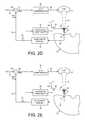
- FIG. 2Dshows an embodiment of the present invention wherein a servo loop is disabled by disabling a feedback signal while exciting the microactuator.
- FIG. 2Eshows an embodiment of the present invention wherein the feedback signal is enabled to enable the servo loop after exciting the microactuator.
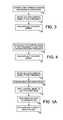
- FIG. 3is a flow diagram according to an embodiment of the present invention wherein an actuator arm is pressed against an inner diameter crash stop while exciting the microactuator.
- FIG. 4is a flow diagram according to an embodiment of the present invention wherein the microactuator is excited with a test frequency other than a resonant frequency of a load beam.
- FIG. 5Ais a flow diagram according to an embodiment of the present invention wherein after exciting the microactuator, the microactuator is evaluated in response to a position error signal (PES) generated while servoing the head in response to the servo sectors.
- PESposition error signal
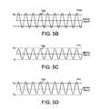
- FIG. 5Bshows an embodiment of the present invention wherein the PES indicates the microactuator is not defective.
- FIGS. 5C-5Dshow embodiments of the present invention wherein the PES indicates the microactuator is defective.
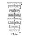
- FIG. 6Ais a flow diagram according to an embodiment of the present invention wherein a PES level is measured before exciting the microactuator, and after exciting the microactuator, wherein a difference between the PES measurements is used to evaluate the microactuator.
- FIG. 6Bshows an embodiment of the present invention wherein the difference between the PES measurements indicates the microactuator is not defective.
- FIG. 6Cshows an embodiment of the present invention wherein the difference between the PES measurements indicates the microactuator is defective.
- FIG. 6Dshows an embodiment of the present invention wherein a slope of a metric is used to evaluate the microactuator.
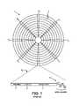
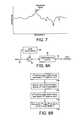
- FIG. 7shows an embodiment of the present invention wherein a frequency response of a microactuator servo loop is used to evaluate the microactuator.
- FIG. 8Ashows an embodiment of the present invention wherein the microactuator servo loop comprises an adapted gain setting.
- FIG. 8Bis a flow diagram according to an embodiment of the present invention wherein after exciting the microactuator the gain of the microactuator servo loop is used to evaluate the microactuator.
- FIG. 9is a flow diagram according to an embodiment of the present invention wherein after exciting the microactuator an induced movement of the microactuator is used to evaluate the microactuator.
- FIG. 10is a flow diagram according to an embodiment of the present invention wherein a difference between an induced voltage generated by the microactuator before and after exciting the microactuator is used to evaluate the microactuator.
- FIG. 11is a flow diagram according to an embodiment of the present invention wherein a stroke of the microactuator is evaluated before and after servoing the head to detect a defect in the microactuator.
- FIG. 2Ashows a disk drive according to an embodiment of the present invention comprising a disk surface 4 1 comprising a plurality of tracks, each track comprising a plurality of servo sectors a first head 2 1 coupled to a distal end of an actuator arm 6 1 , and a voice coil motor (VCM) 8 and a first microactuator 10 1 operable to actuate the first head 2 1 over the first disk surface 4 1 .
- the disk drivefurther comprises control circuitry 12 for executing the flow diagram of FIG.
- the headis first servoed in response to the servo sectors (step 14 ), and after first servoing the head, a manufacturing procedure is executed by controlling the VCM and the microactuator to servo the head while accessing the disk surface (step 16 ). After executing the manufacturing procedure, the head is second servoed in response to the servo sectors (step 18 ), and the microactuator is evaluated in response to the first and second servoing (step 20 ).
- each disk surface(e.g., disk surface 4 1 ) comprises a plurality of tracks 22 defined by a plurality of servo sectors 24 1 - 24 n .
- the control circuitry 12demodulates the read signal 26 into a position error signal (PES).
- PESposition error signal
- the PESis filtered by a suitable compensation filter to generate a control signal 28 applied to the VCM 8 .
- the VCM 8rotates an actuator arm 6 1 about a pivot in order to position the head 2 1 radially over the disk 4 1 in a direction that reduces the PES.
- the control circuitry 12may also generate a control signal 30 applied to the microactuator 10 1 in response to the PES to further increase the bandwidth of the servo system.
- the disk drivecomprises a ramp 32 located at an outer edge of the disk for unloading the actuator arm 6 1 while the disk drive is idle.
- the control circuitry 12may evaluate the microactuator 10 1 using the ramp 32 , for example, by measuring a voltage induced by the microactuator 10 1 when the load beam 34 1 is deflected as the actuator arm 6 1 strikes the ramp 32 .
- FIG. 2Cshows an embodiment of the present invention wherein the VCM 8 rotates a plurality of actuator arms 6 1 - 6 n about a pivot in order to coarsely position a plurality of heads 2 1 - 2 n over respective disk surfaces 4 1 - 4 n .
- a plurality of microactuators 10 1 - 10 nare also provided for fine positioning each head, wherein in one embodiment disclosed below, the microactuators 10 1 - 10 n are simultaneously excited at the test frequency and then evaluated individually.
- any suitable manufacturing proceduremay be executed at step 16 of FIG. 2B , such as initial burn in (IBI) procedures for testing and calibrating various components of the disk drive by accessing the disk surface.
- Another manufacturing proceduremay perform a defect scan of each disk surface by writing/reading a test pattern to each data sector in order to map out defective data sectors.
- Yet another manufacturing proceduremay servo write the servo sectors 24 1 - 24 n to each disk surface while servoing off of a seed pattern (e.g., spiral seed tracks).
- a seed patterne.g., spiral seed tracks.
- Each of these manufacturing proceduresemploy the microactuators 10 1 - 10 n to access the disk surfaces, and therefore these manufacturing procedures essentially stress the microactuators 10 1 - 10 n which may accentuate certain defects (e.g., cracks).
- an independent IBI proceduremay also be executed to further stress the microactuators 10 1 - 10 n by exciting the microactuators 10 1 - 10 n at a test frequency without servoing the head in response to the servo sectors (i.e., without accessing the disk surface).
- FIG. 2Dshows control circuitry according to an embodiment of the present invention for servoing the head 2 1 over the disk surface 4 1 using the VCM 8 and the microactuator 10 1 .
- a read/write channel 36processes the read signal 26 to demodulate the servo sectors 24 1 - 24 n into an estimated position 38 of the head 2 1 over the disk surface 4 1 .
- the estimated position 38is subtracted 40 from a reference position 42 to generate the PES 44 .
- the PES 44is processed by a VCM compensator 46 to generate a control signal 28 applied to the VCM 8 and processed by a microactuator compensator 48 to generate a control signal 30 applied to the microactuator 10 1 .
- the servo loop for servoing the headis disabled by disabling the feedback in FIG. 2D by opening switch 52 .
- the switch 52 in FIG. 2Dis illustrative; however, the servo loop may be disabled using any suitable technique.
- a current value of the PES 44may be stored in a register and applied as a constant to the VCM compensator 46 while exciting the microactuator 10 1 .
- control circuitrymay servo the head over a target radial location (e.g., a middle diameter of the disk) with the servo loop enabled, and then disable the servo loop prior to exciting the microactuator 10 1 .
- control circuitrymay servo the head to an inner diameter of the disk and then press the actuator arm against an inner diameter crash stop (step 54 ) prior to exciting the microactuator 10 1 . This embodiment ensures that data recorded on the disk is not corrupted if the head contacts the disk surface while exciting the microactuator 10 1 .
- a switch 54conceptually applies the test frequency 50 (a sinusoidal signal) to the microactuator 10 1 in order to excite the microactuator 10 1 .
- Any suitable frequencymay be selected as the test frequency to excite the microactuator, wherein in an embodiment shown in FIG. 4 the test frequency is substantially different from a resonant frequency of the load beam 34 1 (step 56 ) so as not to damage the load beam 34 1 or the interconnect of the load beam 34 1 to the actuator arm 6 1 .
- an amplitude of the test frequency 50is substantially higher than an amplitude of the control signal 30 applied during normal operation of the disk drive so as to minimize the time required to accentuate potential cracks in the microactuator 10 1 .
- the test frequencymay excite the microactuator 10 1 after unloading the actuator arm 6 1 onto the ramp 32 ; however, in this embodiment the vibrations of the load beam 34 1 may result in undesirable wear of the ramp 32 .
- the servo systemAfter exciting the microactuator 10 1 at the test frequency, the servo system is enabled (shown in FIG. 2E as closing switch 52 ) and the microactuator 10 1 evaluated to detect a crack or other defect in the microactuator 10 1 .
- Any suitable techniquemay be employed to evaluate the microactuator 10 1 , wherein in one embodiment shown in the flow diagram of FIG. 5A , the head is positioned over a servo track (step 58 ) by reading the servo sectors, and then a control signal applied to the microactuator 10 1 to offset the head (step 60 ).
- the servo sectorsare read to generate a PES (step 62 ), and the PES evaluated to detect a crack or other defect in the microactuator (step 64 ).
- FIG. 5AAny suitable technique may be employed to evaluate the microactuator 10 1 , wherein in one embodiment shown in the flow diagram of FIG. 5A , the head is positioned over a servo track (step 58 ) by reading the serv
- a sinusoidal control signal 66is applied to the microactuator 10 1 in order to offset the head from the servo track to generate the PES, wherein any suitable frequency of the control signal 66 may be employed.
- Other embodiments described in greater detail belowmay evaluate the microactuator 10 1 with the microactuator servo loop enabled by configuring switch 54 to select the output of the microactuator compensator 48 as the control signal 30 applied to the microactuator 10 1 .
- FIG. 5Billustrates a sinusoidal PES as a result of applying the sinusoidal control signal 66 to the microactuator 10 1 .
- the PESis compared to thresholds Th+ and Th ⁇ representing an offset from each side of the target servo track, wherein the microactuator 10 1 is considered non-defective if the amplitude of the PES exceeds the thresholds.
- FIG. 5Cshows an example of a defective microactuator 10 1 wherein the PES falls below both thresholds (both sides of the servo track), and
- FIG. 5Dshows an example of a defective microactuator 10 1 wherein the PES falls below one of the thresholds (one side of the servo track).
- FIG. 6Ais a flow diagram according to an embodiment of the present invention for evaluating the microactuator 10 1 , wherein the head is positioned over a servo track (step 66 ) by reading the servo sectors, the head offset from the servo track by applying a control signal to the microactuator (step 68 ), and the servo sectors read to generate a first PES (step 70 ). The microactuator is then excited at the test frequency to accentuate cracks (step 72 ).
- the headAfter exciting the microactuator, the head is repositioned over the servo track (step 74 ), the head offset from the servo track by applying a control signal to the microactuator (step 76 ), and the servo sectors read to generate a second PES (step 78 ).
- the microactuatoris then evaluated by comparing the second PES to the first PES (step 80 ).
- This embodimentis illustrated in FIGS. 6B and 6C wherein if the difference between the first and second PES is greater than a threshold, the microactuator is considered defective. Accordingly, in this embodiment the microactuator is evaluated relative to a change in performance after exciting the microactuator as opposed to evaluating the absolute performance relative to an expected level.
- FIG. 6Dillustrates an embodiment of the present invention wherein a rate of change of a metric (e.g., absolute measurement or difference measurement) is evaluated to determine whether the microactuator 10 1 is defective.
- a rate of change of a metrice.g., absolute measurement or difference measurement
- the microactuator 10 1may be considered defective if the slope (positive or negative) of the metric exceeds a threshold.
- the microactuator 10 1may be excited multiple times and the metric measured after each excitation in order to measure the rate of change of the metric.
- the rate of change of the metricmay be an indication of future failure even if the current value of the metric would otherwise pass the evaluation.
- FIG. 7shows an embodiment of the present invention wherein a frequency response (e.g., a magnitude response or a phase response) of the microactuator servo loop is evaluated to determine whether the microactuator is defective.
- a frequency responsee.g., a magnitude response or a phase response
- the absolute magnitude of the frequency responsemay be evaluated, and in another embodiment, a difference between the magnitude before and after exciting the microactuator may be evaluated.
- the microactuator servo loopmay be evaluated open loop or closed loop by appropriately configuring switch 54 of FIG. 2E (where switch 54 represents a concept that may be implemented using any suitable technique).
- switch 54represents a concept that may be implemented using any suitable technique.
- a resonant peak in the frequency response as shown in FIG. 7is evaluated in order to evaluate the microactuator.
- a defect in the microactuatormay change the resonant peak amplitude or shift the resonant peak frequency (absolute measurement or difference before and after excitation). Any suitable resonant peak may be evaluated, such as a sway mode resonance of the load beam 34 1 .
- FIG. 8Ashows control circuitry for implementing the microactuator compensator 48 according to an embodiment wherein a gain 82 of a compensation filter 84 is adapted 86 in response to the PES 44 .
- the microactuator servo loopis calibrated in order to adapt the gain 82 . If there is a crack in the microactuator that reduces its sensitivity, the adjusted gain 82 will change to compensate for the reduced sensitivity. Accordingly, the crack may be detected if the adjusted gain 82 exceeds a threshold.
- FIG. 8Bis a flow diagram according to an embodiment of the present invention wherein the head is positioned over a servo track in response to the servo sectors in order to adjust the gain of the microactuator servo loop to a first value (step 88 ). The microactuator is then excited at the test frequency (step 90 ) to accentuate cracks or other defects. The head is then repositioned over the servo track and the gain adjusted to a second value (step 92 ). The difference between the first and second gain values is then evaluated to detect whether the microactuator is defective (step 94 ). In one embodiment, the flow diagram of FIG. 8B may be executed multiple times in order to develop a rate of change of the gain value as illustrated in FIG. 6D .
- FIG. 9is a flow diagram according to an embodiment of the present invention wherein after exciting the microactuator at the test frequency (step 96 ), a movement of the load beam is induced in order to induce a movement in the microactuator (step 98 ).
- Any suitable techniquemay be employed to induce the movement, such as by reducing a fly height of the head until the head contacts the disk (touchdown), or moving the actuator arm until it contacts a crash stop (inner or outer diameter), or until the load beam contacts the ramp.
- Other embodimentsmay simply accelerate and/or decelerate the actuator arm using a special calibration seek profile in order to induce movement of the load beam.
- An induced voltageis detected that is generated by the microactuator due to the induced movement (step 100 ), and the induced voltage is evaluated to detect a defect in the microactuator (step 102 ).
- FIG. 10is a flow diagram according to an embodiment wherein prior to exciting the microactuator at the test frequency, a movement of the load beam is induced in order to induce a movement in the microactuator (step 104 ). A first induced voltage is detected in response to the induced movement (step 106 ) and then the microactuator is excited at the test frequency (step 108 ). A movement of the load beam is again induced in order to induce a movement in the microactuator (step 110 ), and a second induced voltage is detected in response to the induced movement (step 112 ). A difference between the first and second induced voltages is evaluated in order to detect a defect in the microactuator (step 114 ). In one embodiment, the flow diagram of FIG. 10 may be executed multiple times in order to develop a rate of change of the induced voltage as illustrated in FIG. 6D .
- the step of exciting the microactuator at the test frequencymay be replaced with, or augmented with, the step of executing manufacturing procedures (e.g., IBI, defect scan, servo writing, etc.) as described above with reference to FIG. 2B . That is, using the microactuator to servo the head during the manufacturing procedures may sufficiently stress the microactuator to accentuate defects, such as cracks. Comparing operation of the microactuator before and after executing the manufacturing procedures enables the detection of defects so that the disk drive can be reworked, or the microactuator disabled.
- manufacturing procedurese.g., IBI, defect scan, servo writing, etc.
- the disk drivemay format the corresponding disk surface to a lower radial density of data tracks that are accessible using the VCM alone. This embodiment avoids the expense of replacing a defective microactuator with the tradeoff of reducing the capacity of the disk drive.
- FIG. 11is a flow diagram according to an embodiment of the present invention wherein a stroke of the microactuator is evaluated before and after servoing the head to detect a defect in the microactuator.
- a first stroke of the microactuatoris measured (step 116 ), and after measuring the first stroke, the VCM and the microactuator are used to servo the head while accessing the disk surface (step 118 ), for example, during a manufacturing procedure or during normal operation of the disk drive while deployed in the field.
- a second stroke of the microactuatoris measured (step 120 ).
- the microactuatoris then evaluated in response to the first and second strokes (step 122 ), such as by evaluating a difference between the first and second strokes or a rate of change of the stroke.
- the stroke of the microactuatormay be measured using any suitable technique, such as one or more of the techniques described above (i.e., measuring an amplitude of a PES, measuring a frequency response of the servo system, adapting a gain of the servo system, inducing a movement of the microactuator, etc.).
- control circuitrymay be implemented within a read channel integrated circuit, or in a component separate from the read channel, such as a disk controller, or certain steps described above may be performed by a read channel and others by a disk controller.
- the read channel and disk controllerare implemented as separate integrated circuits, and in an alternative embodiment they are fabricated into a single integrated circuit or system on a chip (SOC).
- the control circuitrymay include a suitable preamp circuit implemented as a separate integrated circuit, integrated into the read channel or disk controller circuit, or integrated into an SOC.
- control circuitrycomprises a microprocessor executing instructions, the instructions being operable to cause the microprocessor to perform the steps of the flow diagrams described herein.
- the instructionsmay be stored in any computer-readable medium. In one embodiment, they may be stored on a non-volatile semiconductor memory external to the microprocessor, or integrated with the microprocessor in a SOC. In another embodiment, the instructions are stored on the disk and read into a volatile semiconductor memory when the disk drive is powered on. In yet another embodiment, the control circuitry comprises suitable logic circuitry, such as state machine circuitry.
Landscapes
- Moving Of The Head To Find And Align With The Track (AREA)
Abstract
Description
Claims (28)
Priority Applications (1)
| Application Number | Priority Date | Filing Date | Title |
|---|---|---|---|
| US12/797,883US8547657B1 (en) | 2010-06-10 | 2010-06-10 | Disk drive detecting defective microactuator |
Applications Claiming Priority (1)
| Application Number | Priority Date | Filing Date | Title |
|---|---|---|---|
| US12/797,883US8547657B1 (en) | 2010-06-10 | 2010-06-10 | Disk drive detecting defective microactuator |
Publications (1)
| Publication Number | Publication Date |
|---|---|
| US8547657B1true US8547657B1 (en) | 2013-10-01 |
Family
ID=49229886
Family Applications (1)
| Application Number | Title | Priority Date | Filing Date |
|---|---|---|---|
| US12/797,883Expired - Fee RelatedUS8547657B1 (en) | 2010-06-10 | 2010-06-10 | Disk drive detecting defective microactuator |
Country Status (1)
| Country | Link |
|---|---|
| US (1) | US8547657B1 (en) |
Cited By (21)
| Publication number | Priority date | Publication date | Assignee | Title |
|---|---|---|---|---|
| US8797664B1 (en) | 2012-12-22 | 2014-08-05 | Western Digital Technologies, Inc. | Polarity detection of piezoelectric actuator in disk drive |
| US8964179B2 (en) | 2013-02-21 | 2015-02-24 | Western Digital Technologies, Inc. | Method and apparatus for measuring a pitch static attitude of a head stack assembly |
| US20150062748A1 (en)* | 2013-09-03 | 2015-03-05 | Hutchinson Technology Incorporated | Motor polarity testing of a dual stage actuated disk drive head suspension |
| US9022444B1 (en) | 2013-05-20 | 2015-05-05 | Western Digital Technologies, Inc. | Vacuum nozzle having back-pressure release hole |
| US9120232B1 (en) | 2013-07-26 | 2015-09-01 | Western Digital Technologies, Inc. | Vacuum pick-up end effector with improved vacuum reading for small surface |
| US9153283B1 (en) | 2014-09-30 | 2015-10-06 | Western Digital Technologies, Inc. | Data storage device compensating for hysteretic response of microactuator |
| US9150360B1 (en) | 2013-05-16 | 2015-10-06 | Western Digital Technologies, Inc. | Mechanism to deliver fastener vertically |
| US9157817B1 (en) | 2014-06-09 | 2015-10-13 | Western Digital Technologies, Inc. | HSA swage metrology calibration using solid weight gauge and torque sensor |
| US9180563B2 (en) | 2013-03-08 | 2015-11-10 | Western Digital Technologies, Inc. | De-swage machine for removal of a head from a head stack assembly and method of using the same |
| US9230579B1 (en) | 2012-09-21 | 2016-01-05 | Western Digital Technologies, Inc. | Comb gripper for use with a shipping comb and a ramp in the assembly of a disk drive |
| US9236071B1 (en) | 2014-12-21 | 2016-01-12 | Western Digital Technologies, Inc. | Etching continuous periodic pattern on a suspension to adjust pitch and roll static attitude |
| US9275677B1 (en) | 2010-09-30 | 2016-03-01 | Western Digital Technologies, Inc. | Hard disk drive top cover removal |
| US9286922B1 (en) | 2015-06-26 | 2016-03-15 | Western Digital Technologies, Inc. | Adaptive tacking of head gimbal assembly long tail and HSA arm slot |
| US9299372B1 (en) | 2015-04-29 | 2016-03-29 | Western Digital Technologies, Inc. | Swage key enabling simultaneous transfer of two head gimbal assemblies onto two corresponding actuator pivot flex assembly arms |
| US9355666B1 (en)* | 2013-09-30 | 2016-05-31 | Western Digital Technologies, Inc. | Disk drive measuring stroke difference between heads by detecting a difference between ramp contact |
| US9404939B1 (en) | 2014-06-24 | 2016-08-02 | Western Digital (Fremont), Llc | Pre-amplifier cartridge for test equipment of head gimbal assembly |
| US9737979B1 (en) | 2014-02-13 | 2017-08-22 | Western Digital Technologies, Inc. | Vacuum embedded bit for screw drivers |
| US9799377B1 (en) | 2015-05-01 | 2017-10-24 | Western Digital Technologies, Inc. | Gas-charging head with integral valves |
| US9895725B1 (en) | 2014-10-07 | 2018-02-20 | Western Digital Technologies, Inc. | Disk clamp and motor hub cleaning with stamping adhesive |
| US9996071B2 (en) | 2014-06-24 | 2018-06-12 | Western Digital Technologies, Inc. | Moveable slider for use in a device assembly process |
| US10039219B1 (en) | 2015-09-28 | 2018-07-31 | Western Digital Technologies, Inc. | Method and devices for picking and placing workpieces into devices under manufacture using dual robots |
Citations (30)
| Publication number | Priority date | Publication date | Assignee | Title |
|---|---|---|---|---|
| US2728222A (en) | 1950-10-17 | 1955-12-27 | Leitz Ernst Gmbh | Apparatus for measuring surface irregularities |
| US4760358A (en) | 1985-08-07 | 1988-07-26 | Murata Manufacturing Co., Ltd. | Piezoelectric element |
| US5118982A (en) | 1989-05-31 | 1992-06-02 | Nec Corporation | Thickness mode vibration piezoelectric transformer |
| US5262643A (en) | 1992-06-12 | 1993-11-16 | International Business Machines Corp. | Automatic tip approach method and apparatus for scanning probe microscope |
| US5301558A (en) | 1992-10-02 | 1994-04-12 | Caterpillar Inc. | Testing apparatus for a multilayer piezoelectric actuator |
| USRE37030E1 (en) | 1992-12-24 | 2001-01-30 | Renishaw Plc | Touch probe and signal processing circuit therefor |
| US6249890B1 (en) | 1998-06-05 | 2001-06-19 | Seagate Technology Llc | Detecting head readback response degradation in a disc drive |
| US6510752B1 (en) | 1999-02-22 | 2003-01-28 | Seagate Technology Llc | Method and apparatus for testing microactuators on a suspension assembly |
| US20030076121A1 (en) | 2001-10-23 | 2003-04-24 | Wei Guo | Peizoelectric microactuator and sensor failure detection in disk drives |
| US6556028B1 (en) | 2001-05-07 | 2003-04-29 | Storage Test Solutions, Inc. | Method and apparatus for detecting defects in piezoelectric actuators |
| US6639411B1 (en) | 2000-09-05 | 2003-10-28 | Hutchinson Technology Incorporated | Microactuated suspension motor failure detection system |
| US6831807B2 (en) | 2001-11-05 | 2004-12-14 | Matsushita Electric Industrial Co., Ltd. | Head positioner and disk drive using the same |
| US6975477B1 (en) | 2002-05-03 | 2005-12-13 | Maxtor Corporation | Micro actuator DC gain calibration scheme for HDD dual-stage actuator systems |
| US6977793B2 (en) | 2004-03-16 | 2005-12-20 | Hitachi Global Storage Technologies Netherlands B.V. | Magnetic recording disk drive with dual-stage actuator and control system with multiple controllers |
| US7009804B2 (en) | 2004-07-29 | 2006-03-07 | Samsung Electronics Co., Ltd. | Method and apparatus for micro-actuator stroke sensitivity calibration in a hard disk drive |
| US7072134B1 (en) | 2005-02-03 | 2006-07-04 | Hitachi Global Storage Technologies Netherlands B.V. | Dual-stage actuator disk drive with secondary actuator failure detection and recovery using relative-position signal |
| US7075748B2 (en) | 2004-11-24 | 2006-07-11 | Hitachi Global Storage Technologies Netherlands B.V. | Disk drive with a dual-stage actuator and failure detection and recovery system for the secondary actuator |
| US7079338B1 (en) | 2005-06-03 | 2006-07-18 | Hitachi Global Storagetechnologies Netherlands B.V. | Dual-stage actuator disk drive with method for secondary-actuator failure detection and recovery while track-following |
| US7079339B1 (en) | 2005-06-03 | 2006-07-18 | Hitachi Global Storage Technologies Netherlands B.V. | Dual-stage actuator disk drive with method for secondary-actuator failure detection and recovery using a relative-position sensor while track following |
| US20060171062A1 (en)* | 2005-02-03 | 2006-08-03 | Toshiki Hirano | Method for secondary-actuator failure detection and recovery in a dual-stage actuator disk drive |
| US7124654B1 (en) | 2004-09-30 | 2006-10-24 | Western Digital (Fremont), Inc. | Method for determining a microactuator range of movement |
| UA20943U (en) | 2006-09-11 | 2007-02-15 | Valerii Mykhailovych Sharapov | Device for testing a bimorph piezoelectric element |
| UA20940U (en) | 2006-09-11 | 2007-02-15 | Valerii Mykhailovych Sharapov | Device for testing a bimorph piezoelectric element |
| US7336434B2 (en) | 2005-07-18 | 2008-02-26 | Hitachi Global Storage Technologies Netherlands B.V. | Predictive failure analysis of thermal flying height control system and method |
| US7423837B2 (en) | 2006-03-23 | 2008-09-09 | Seagate Technology Llc | Micro actuator gain calibration based on a sinusoidal input signal |
| WO2009128546A1 (en) | 2008-04-18 | 2009-10-22 | 日本碍子株式会社 | Method for testing piezoelectric/electrostrictive device, testing apparatus, and method for adjusting piezoelectric/electrostrictive device |
| US20090303839A1 (en) | 2007-07-31 | 2009-12-10 | Manoj Narayanan | Stress-biased cymbals incorporating a shape memory alloy |
| US20100037674A1 (en) | 2008-03-21 | 2010-02-18 | The Regents Of The University Of California | Test Surfaces Useful for Calibration of Surface Profilometers |
| US7768276B2 (en) | 2006-11-06 | 2010-08-03 | Sae Magnetics (H. K.) Ltd. | Systems and methods for identifying problems with PZT elements of micro-actuators |
| US8335049B1 (en) | 2010-06-07 | 2012-12-18 | Western Digital Technologies, Inc. | Disk drive detecting crack in microactuator |
- 2010
- 2010-06-10USUS12/797,883patent/US8547657B1/ennot_activeExpired - Fee Related
Patent Citations (33)
| Publication number | Priority date | Publication date | Assignee | Title |
|---|---|---|---|---|
| US2728222A (en) | 1950-10-17 | 1955-12-27 | Leitz Ernst Gmbh | Apparatus for measuring surface irregularities |
| US4760358A (en) | 1985-08-07 | 1988-07-26 | Murata Manufacturing Co., Ltd. | Piezoelectric element |
| US5118982A (en) | 1989-05-31 | 1992-06-02 | Nec Corporation | Thickness mode vibration piezoelectric transformer |
| US5262643A (en) | 1992-06-12 | 1993-11-16 | International Business Machines Corp. | Automatic tip approach method and apparatus for scanning probe microscope |
| US5301558A (en) | 1992-10-02 | 1994-04-12 | Caterpillar Inc. | Testing apparatus for a multilayer piezoelectric actuator |
| USRE37030E1 (en) | 1992-12-24 | 2001-01-30 | Renishaw Plc | Touch probe and signal processing circuit therefor |
| US6249890B1 (en) | 1998-06-05 | 2001-06-19 | Seagate Technology Llc | Detecting head readback response degradation in a disc drive |
| US6510752B1 (en) | 1999-02-22 | 2003-01-28 | Seagate Technology Llc | Method and apparatus for testing microactuators on a suspension assembly |
| US6870377B2 (en) | 2000-09-05 | 2005-03-22 | Hutchinson Technology Incorporated | Method for detecting piezoelectric element failures in head suspensions |
| US6639411B1 (en) | 2000-09-05 | 2003-10-28 | Hutchinson Technology Incorporated | Microactuated suspension motor failure detection system |
| US6556028B1 (en) | 2001-05-07 | 2003-04-29 | Storage Test Solutions, Inc. | Method and apparatus for detecting defects in piezoelectric actuators |
| US20030076121A1 (en) | 2001-10-23 | 2003-04-24 | Wei Guo | Peizoelectric microactuator and sensor failure detection in disk drives |
| US6861854B1 (en) | 2001-10-23 | 2005-03-01 | Maxtor Corporation | Peizoelectric microactuator and sensor failure detection in disk drives |
| US6831807B2 (en) | 2001-11-05 | 2004-12-14 | Matsushita Electric Industrial Co., Ltd. | Head positioner and disk drive using the same |
| US6975477B1 (en) | 2002-05-03 | 2005-12-13 | Maxtor Corporation | Micro actuator DC gain calibration scheme for HDD dual-stage actuator systems |
| US6977793B2 (en) | 2004-03-16 | 2005-12-20 | Hitachi Global Storage Technologies Netherlands B.V. | Magnetic recording disk drive with dual-stage actuator and control system with multiple controllers |
| US7009804B2 (en) | 2004-07-29 | 2006-03-07 | Samsung Electronics Co., Ltd. | Method and apparatus for micro-actuator stroke sensitivity calibration in a hard disk drive |
| US7124654B1 (en) | 2004-09-30 | 2006-10-24 | Western Digital (Fremont), Inc. | Method for determining a microactuator range of movement |
| US7075748B2 (en) | 2004-11-24 | 2006-07-11 | Hitachi Global Storage Technologies Netherlands B.V. | Disk drive with a dual-stage actuator and failure detection and recovery system for the secondary actuator |
| US20060171062A1 (en)* | 2005-02-03 | 2006-08-03 | Toshiki Hirano | Method for secondary-actuator failure detection and recovery in a dual-stage actuator disk drive |
| US7106552B2 (en) | 2005-02-03 | 2006-09-12 | Hitachi Global Storage Technologies Netherlands B.V. | Method for secondary-actuator failure detection and recovery in a dual-stage actuator disk drive |
| US7072134B1 (en) | 2005-02-03 | 2006-07-04 | Hitachi Global Storage Technologies Netherlands B.V. | Dual-stage actuator disk drive with secondary actuator failure detection and recovery using relative-position signal |
| US7079338B1 (en) | 2005-06-03 | 2006-07-18 | Hitachi Global Storagetechnologies Netherlands B.V. | Dual-stage actuator disk drive with method for secondary-actuator failure detection and recovery while track-following |
| US7079339B1 (en) | 2005-06-03 | 2006-07-18 | Hitachi Global Storage Technologies Netherlands B.V. | Dual-stage actuator disk drive with method for secondary-actuator failure detection and recovery using a relative-position sensor while track following |
| US7336434B2 (en) | 2005-07-18 | 2008-02-26 | Hitachi Global Storage Technologies Netherlands B.V. | Predictive failure analysis of thermal flying height control system and method |
| US7423837B2 (en) | 2006-03-23 | 2008-09-09 | Seagate Technology Llc | Micro actuator gain calibration based on a sinusoidal input signal |
| UA20940U (en) | 2006-09-11 | 2007-02-15 | Valerii Mykhailovych Sharapov | Device for testing a bimorph piezoelectric element |
| UA20943U (en) | 2006-09-11 | 2007-02-15 | Valerii Mykhailovych Sharapov | Device for testing a bimorph piezoelectric element |
| US7768276B2 (en) | 2006-11-06 | 2010-08-03 | Sae Magnetics (H. K.) Ltd. | Systems and methods for identifying problems with PZT elements of micro-actuators |
| US20090303839A1 (en) | 2007-07-31 | 2009-12-10 | Manoj Narayanan | Stress-biased cymbals incorporating a shape memory alloy |
| US20100037674A1 (en) | 2008-03-21 | 2010-02-18 | The Regents Of The University Of California | Test Surfaces Useful for Calibration of Surface Profilometers |
| WO2009128546A1 (en) | 2008-04-18 | 2009-10-22 | 日本碍子株式会社 | Method for testing piezoelectric/electrostrictive device, testing apparatus, and method for adjusting piezoelectric/electrostrictive device |
| US8335049B1 (en) | 2010-06-07 | 2012-12-18 | Western Digital Technologies, Inc. | Disk drive detecting crack in microactuator |
Cited By (23)
| Publication number | Priority date | Publication date | Assignee | Title |
|---|---|---|---|---|
| US9275677B1 (en) | 2010-09-30 | 2016-03-01 | Western Digital Technologies, Inc. | Hard disk drive top cover removal |
| US9230579B1 (en) | 2012-09-21 | 2016-01-05 | Western Digital Technologies, Inc. | Comb gripper for use with a shipping comb and a ramp in the assembly of a disk drive |
| US8797664B1 (en) | 2012-12-22 | 2014-08-05 | Western Digital Technologies, Inc. | Polarity detection of piezoelectric actuator in disk drive |
| US8964179B2 (en) | 2013-02-21 | 2015-02-24 | Western Digital Technologies, Inc. | Method and apparatus for measuring a pitch static attitude of a head stack assembly |
| US9308609B2 (en) | 2013-03-08 | 2016-04-12 | Western Digital Technologies, Inc. | De-swage machine for removal of a head from a head stack assembly and method of using the same |
| US9180563B2 (en) | 2013-03-08 | 2015-11-10 | Western Digital Technologies, Inc. | De-swage machine for removal of a head from a head stack assembly and method of using the same |
| US9150360B1 (en) | 2013-05-16 | 2015-10-06 | Western Digital Technologies, Inc. | Mechanism to deliver fastener vertically |
| US9022444B1 (en) | 2013-05-20 | 2015-05-05 | Western Digital Technologies, Inc. | Vacuum nozzle having back-pressure release hole |
| US9120232B1 (en) | 2013-07-26 | 2015-09-01 | Western Digital Technologies, Inc. | Vacuum pick-up end effector with improved vacuum reading for small surface |
| US20150062748A1 (en)* | 2013-09-03 | 2015-03-05 | Hutchinson Technology Incorporated | Motor polarity testing of a dual stage actuated disk drive head suspension |
| US9208807B2 (en)* | 2013-09-03 | 2015-12-08 | Hutchinson Technology Incorporated | Motor polarity testing of a dual stage actuated disk drive head suspension |
| US9355666B1 (en)* | 2013-09-30 | 2016-05-31 | Western Digital Technologies, Inc. | Disk drive measuring stroke difference between heads by detecting a difference between ramp contact |
| US9737979B1 (en) | 2014-02-13 | 2017-08-22 | Western Digital Technologies, Inc. | Vacuum embedded bit for screw drivers |
| US9157817B1 (en) | 2014-06-09 | 2015-10-13 | Western Digital Technologies, Inc. | HSA swage metrology calibration using solid weight gauge and torque sensor |
| US9404939B1 (en) | 2014-06-24 | 2016-08-02 | Western Digital (Fremont), Llc | Pre-amplifier cartridge for test equipment of head gimbal assembly |
| US9996071B2 (en) | 2014-06-24 | 2018-06-12 | Western Digital Technologies, Inc. | Moveable slider for use in a device assembly process |
| US9153283B1 (en) | 2014-09-30 | 2015-10-06 | Western Digital Technologies, Inc. | Data storage device compensating for hysteretic response of microactuator |
| US9895725B1 (en) | 2014-10-07 | 2018-02-20 | Western Digital Technologies, Inc. | Disk clamp and motor hub cleaning with stamping adhesive |
| US9236071B1 (en) | 2014-12-21 | 2016-01-12 | Western Digital Technologies, Inc. | Etching continuous periodic pattern on a suspension to adjust pitch and roll static attitude |
| US9299372B1 (en) | 2015-04-29 | 2016-03-29 | Western Digital Technologies, Inc. | Swage key enabling simultaneous transfer of two head gimbal assemblies onto two corresponding actuator pivot flex assembly arms |
| US9799377B1 (en) | 2015-05-01 | 2017-10-24 | Western Digital Technologies, Inc. | Gas-charging head with integral valves |
| US9286922B1 (en) | 2015-06-26 | 2016-03-15 | Western Digital Technologies, Inc. | Adaptive tacking of head gimbal assembly long tail and HSA arm slot |
| US10039219B1 (en) | 2015-09-28 | 2018-07-31 | Western Digital Technologies, Inc. | Method and devices for picking and placing workpieces into devices under manufacture using dual robots |
Similar Documents
| Publication | Publication Date | Title |
|---|---|---|
| US8547657B1 (en) | Disk drive detecting defective microactuator | |
| US8335049B1 (en) | Disk drive detecting crack in microactuator | |
| US8699173B1 (en) | Disk drive detecting touchdown event by evaluating frequency response of a touchdown metric | |
| US8094401B1 (en) | Writing high frequency pattern over a DC background to detect skip track erasure for a disk drive | |
| US8483027B1 (en) | Disk drive qualifying head/disk interface using jitter seek excitation | |
| US8743495B1 (en) | Disk drive detecting track squeeze when circular tracks are defined from non-circular servo tracks | |
| US8786976B1 (en) | Disk drive detecting when head is on ramp | |
| US8760792B1 (en) | Methods and devices for determining thermally-induced expansion of magnetic recording media | |
| US8730612B1 (en) | Disk drive evaluating ratio of fly height setting for first and second heads to verify operability | |
| US8605384B1 (en) | Disk drive performing lifetime logging of microactuator sensitivity | |
| US8300348B1 (en) | Disk drive detecting disk boundaries using microactuator | |
| US20120327533A1 (en) | Disk drive mapping out data tracks to avoid thermal asperities | |
| US8094396B1 (en) | Media defect scan | |
| US8553351B1 (en) | Disk drive correcting track ID in response to an estimated radial location and a burst PES | |
| US7583466B2 (en) | Disk drive determining operating fly height by detecting head disk contact from disk rotation time | |
| US8634283B1 (en) | Disk drive performing in-drive spiral track writing | |
| US7688540B1 (en) | Disk drive selecting TPI profile by estimating head geometry | |
| US7457069B2 (en) | Magnetic disk drive with flying height control, control method, and manufacturing method | |
| US10699736B1 (en) | Data storage device detecting abnormality with a write assist element based on slope of protrusion | |
| US7079337B2 (en) | Bi staple flying height detection by BEMF control profile and data integrity problem protection | |
| US20070188907A1 (en) | Media drive and control method for the same | |
| US8922939B1 (en) | Disk drive generating feed-forward fly height control based on temperature sensitive fly height sensor | |
| US9953674B2 (en) | Characterizing a sensing circuit of a data storage device | |
| US8902538B1 (en) | Disk drive detecting crack in microactuator | |
| US8891192B1 (en) | Disk drive calibrating parameter by injecting noise signal and measuring off-track read capability |
Legal Events
| Date | Code | Title | Description |
|---|---|---|---|
| AS | Assignment | Owner name:WESTERN DIGITAL TECHNOLOGIES, INC., CALIFORNIA Free format text:ASSIGNMENT OF ASSIGNORS INTEREST;ASSIGNORS:LIU, YANNING;LAATSCH, RAINER H.;TONG, ANDREW H.;SIGNING DATES FROM 20100610 TO 20100611;REEL/FRAME:024521/0651 | |
| AS | Assignment | Owner name:U.S. BANK NATIONAL ASSOCIATION, AS COLLATERAL AGENT, CALIFORNIA Free format text:SECURITY AGREEMENT;ASSIGNOR:WESTERN DIGITAL TECHNOLOGIES, INC.;REEL/FRAME:038744/0281 Effective date:20160512 Owner name:JPMORGAN CHASE BANK, N.A., AS COLLATERAL AGENT, ILLINOIS Free format text:SECURITY AGREEMENT;ASSIGNOR:WESTERN DIGITAL TECHNOLOGIES, INC.;REEL/FRAME:038722/0229 Effective date:20160512 Owner name:JPMORGAN CHASE BANK, N.A., AS COLLATERAL AGENT, ILLINOIS Free format text:SECURITY AGREEMENT;ASSIGNOR:WESTERN DIGITAL TECHNOLOGIES, INC.;REEL/FRAME:038744/0481 Effective date:20160512 Owner name:JPMORGAN CHASE BANK, N.A., AS COLLATERAL AGENT, IL Free format text:SECURITY AGREEMENT;ASSIGNOR:WESTERN DIGITAL TECHNOLOGIES, INC.;REEL/FRAME:038722/0229 Effective date:20160512 Owner name:U.S. BANK NATIONAL ASSOCIATION, AS COLLATERAL AGEN Free format text:SECURITY AGREEMENT;ASSIGNOR:WESTERN DIGITAL TECHNOLOGIES, INC.;REEL/FRAME:038744/0281 Effective date:20160512 Owner name:JPMORGAN CHASE BANK, N.A., AS COLLATERAL AGENT, IL Free format text:SECURITY AGREEMENT;ASSIGNOR:WESTERN DIGITAL TECHNOLOGIES, INC.;REEL/FRAME:038744/0481 Effective date:20160512 | |
| REMI | Maintenance fee reminder mailed | ||
| LAPS | Lapse for failure to pay maintenance fees | Free format text:PATENT EXPIRED FOR FAILURE TO PAY MAINTENANCE FEES (ORIGINAL EVENT CODE: EXP.) | |
| STCH | Information on status: patent discontinuation | Free format text:PATENT EXPIRED DUE TO NONPAYMENT OF MAINTENANCE FEES UNDER 37 CFR 1.362 | |
| FP | Lapsed due to failure to pay maintenance fee | Effective date:20171001 | |
| AS | Assignment | Owner name:WESTERN DIGITAL TECHNOLOGIES, INC., CALIFORNIA Free format text:RELEASE BY SECURED PARTY;ASSIGNOR:U.S. BANK NATIONAL ASSOCIATION, AS COLLATERAL AGENT;REEL/FRAME:045501/0714 Effective date:20180227 | |
| AS | Assignment | Owner name:WESTERN DIGITAL TECHNOLOGIES, INC., CALIFORNIA Free format text:RELEASE OF SECURITY INTEREST AT REEL 038744 FRAME 0481;ASSIGNOR:JPMORGAN CHASE BANK, N.A.;REEL/FRAME:058982/0556 Effective date:20220203 |