US8546982B2 - Electric machine module cooling system and method - Google Patents
Electric machine module cooling system and methodDownload PDFInfo
- Publication number
- US8546982B2 US8546982B2US13/181,264US201113181264AUS8546982B2US 8546982 B2US8546982 B2US 8546982B2US 201113181264 AUS201113181264 AUS 201113181264AUS 8546982 B2US8546982 B2US 8546982B2
- Authority
- US
- United States
- Prior art keywords
- coolant
- sleeve member
- cavity
- electric machine
- cavity region
- Prior art date
- Legal status (The legal status is an assumption and is not a legal conclusion. Google has not performed a legal analysis and makes no representation as to the accuracy of the status listed.)
- Active
Links
Images


Classifications
- H—ELECTRICITY
- H02—GENERATION; CONVERSION OR DISTRIBUTION OF ELECTRIC POWER
- H02K—DYNAMO-ELECTRIC MACHINES
- H02K9/00—Arrangements for cooling or ventilating
- H02K9/19—Arrangements for cooling or ventilating for machines with closed casing and closed-circuit cooling using a liquid cooling medium, e.g. oil
- H—ELECTRICITY
- H02—GENERATION; CONVERSION OR DISTRIBUTION OF ELECTRIC POWER
- H02K—DYNAMO-ELECTRIC MACHINES
- H02K5/00—Casings; Enclosures; Supports
- H02K5/04—Casings or enclosures characterised by the shape, form or construction thereof
- H02K5/20—Casings or enclosures characterised by the shape, form or construction thereof with channels or ducts for flow of cooling medium
- H02K5/203—Casings or enclosures characterised by the shape, form or construction thereof with channels or ducts for flow of cooling medium specially adapted for liquids, e.g. cooling jackets
Definitions
- Electric machinesoften contained within a machine cavity of a housing, generally include a stator and a rotor, and an air gap between the rotor and the stator.
- Some cooling methodscan include removing the generated heat energy by circulating a coolant through walls of the housing or dispersing a coolant throughout the machine cavity of the housing.
- draining the coolant from the machine cavitycan present difficulties.
- the coolantmay not drain fast enough causing coolant to accumulate within the housing.
- the level of coolantis too great, a portion of the coolant can enter the air gap between the rotor and the stator, which can lead to higher spin losses, decreases in machine output, integration of air within the coolant, and other disadvantages.
- an electric machine modulecomprising a module housing.
- the module housingcan include a sleeve member and at least one end cap.
- An inner wall of the module housingcan at least partially define a machine cavity.
- a coolant jacketcan be positioned within at least a portion of the sleeve member.
- at least one partitioncan be positioned substantially within the coolant jacket. The partition can be dimensioned to at least partially seal a first region of the coolant jacket from a second region of the cooling jacket.
- an electric machine modulecomprising a module housing.
- the module housingcan include a sleeve member and at least one end cap.
- An inner wall of the module housingcan at least partially define a machine cavity.
- a coolant jacketcan be positioned within at least a portion of the sleeve member, and the coolant jacket can include a first region and a second region.
- the first regioncan be at least partially sealed from the second region.
- at least one inletcan be operatively coupled to a portion of the sleeve member adjacent to a portion of the first region of the cooling jacket.
- Some embodiments of the inventionprovide a method for cooling an electric machine module.
- the methodcomprises providing a module housing including an inner wall at least partially defining a machine cavity, a sleeve member, and at least one end cap.
- the methodcan further comprise positioning a coolant jacket within a portion of the sleeve member and partitioning the coolant jacket into a first region and a second region.
- the two regionscan be at least partially sealed from each other.
- Some embodimentscan provide positioning a plurality of coolant apertures through a portion of the inner wall so that at least the first region of the coolant jacket is in fluid communication with the machine cavity.
- FIG. 1is a cross-sectional view of an electric machine module according to one embodiment of the invention.
- FIG. 2is an interior end view of portions of an electric machine module according to one embodiment of the invention.
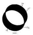
- FIG. 3is a perspective view of an inner sleeve member and partitions according to one embodiment of the invention.
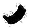
- FIG. 4is a partial cross-sectional view of a sleeve member according to one embodiment of the invention.
- FIG. 1illustrates an electric machine module 10 according to one embodiment of the invention.
- the module 10can include a module housing 12 comprising a sleeve member 14 , a first end cap 16 , and a second end cap 18 .
- An electric machine 20can be housed within a machine cavity 22 at least partially defined by an inner wall 15 of the sleeve member 14 and the end caps 16 , 18 .
- the sleeve member 14 and the end caps 16 , 18can be coupled via conventional fasteners (not shown), or another suitable coupling method, to enclose at least a portion of the electric machine 20 within the machine cavity 22 .
- the housing 12can comprise a substantially cylindrical canister and a single end cap (not shown).
- the module housing 12including the sleeve member 14 and the end caps 16 , 18 , can be fabricated from materials that can generally include thermally conductive properties, such as, but not limited to aluminum or other metals and materials capable of generally withstanding operating temperatures of the electric machine.
- the sleeve member 14can comprise different structures.
- the sleeve member 14can comprise a substantially unitary structure. More specifically, the sleeve member 14 can be manufactured so that at least a portion of the elements of the sleeve member 14 are substantially integral with each other.
- the sleeve member 14can be manufactured using casting, molding, extruding, and other similar manufacturing techniques. As a result, in some embodiments, the structure of the sleeve member 14 can be cast, molded, or extruded at about the same time so that the sleeve member 14 comprises a substantially unitary structure.
- the sleeve member 14can comprise substantially separate components.
- the sleeve member 14can include an inner sleeve member 24 and an outer sleeve member (not shown).
- the inner sleeve member 24 and the outer sleeve membercan be manufactured at different times and can be assembled at a time after manufacture.
- the inner sleeve member 24can be substantially fit around an outer diameter of a portion of the electric machine 20 .
- the inner sleeve member 24 and the outer sleeve membercan be operatively coupled together in the module 10 assembly process.
- the inner and outer sleeve memberscan be operatively coupled so that the coupling between the elements comprises a substantially liquid-tight seal.
- the sleeve member 14can comprise other configurations.
- the electric machine 20can include a rotor 26 , a stator assembly 28 , including stator end turns 30 , and bearings 32 , and can be disposed about an output shaft 36 .
- the stator 28can substantially circumscribe a portion of the rotor 26 .
- the electric machine 20can also include a rotor hub 34 or can have a “hub-less” design (not shown).
- a radial air gap 38can be defined substantially between the stator assembly 28 and the rotor 26 .
- the electric machine 20can be, without limitation, an electric motor, such as a hybrid electric motor, an electric generator, or a vehicle alternator.
- the electric machine 20can be a High Voltage Hairpin (HVH) electric motor or an interior permanent magnet electric motor for hybrid vehicle applications.
- HVHHigh Voltage Hairpin
- Components of the electric machine 20such as, but not limited to, the rotor 26 , the stator assembly 28 , and the stator end turns 30 can generate heat during operation of the electric machine 20 . These components can be cooled to increase the performance and the lifespan of the electric machine 20 .
- the sleeve member 14can comprise a coolant jacket 40 .
- the coolant jacket 40can substantially circumscribe a portion of the electric machine 20 . More specifically, in some embodiments, the coolant jacket 40 can substantially circumscribe a portion of an outer diameter of the stator assembly 28 , including the stator end turns 30 .
- the coolant jacket 40can be at least partially created during manufacture of the sleeve member 14 .
- the sleeve member 14can be manufactured (i.e., cast, molded, extruded, etc.) so that the coolant jacket 40 is formed as a substantially integral element of the sleeve member 14 .
- the coolant jacket 40can be formed by the assembly of the sleeve member 14 .
- the inner sleeve member 24 and the outer sleeve membercan be operatively coupled together so that the coolant jacket 40 is defined between a portion of the two elements.
- the coolant jacket 40can contain a coolant that can comprise transmission fluid, ethylene glycol, an ethylene glycol/water mixture, water, oil, motor oil, or a similar substance.
- the coolant jacket 40can be in fluid communication with a coolant source (not shown) which can pressurize the coolant prior to or as it is being dispersed into the coolant jacket 40 , so that the pressurized coolant can circulate through the coolant jacket 40 .
- at least one coolant inlet 42can be positioned through a portion of the sleeve member 14 to fluidly connect the coolant source and the coolant jacket 40 .
- the sleeve member 14can comprise coolant apertures 44 .
- the coolant apertures 44can extend through a portion of the sleeve member 14 to fluidly connect the coolant jacket 40 and the machine cavity so that a portion of the coolant can flow from the coolant jacket 40 into the machine cavity 22 .
- the coolant apertures 44can be positioned substantially adjacent to the stator end turns 28 . For example, in some embodiments, as the pressurized coolant circulates through the coolant jacket 40 , at least a portion of the coolant can exit the coolant jacket 40 through the coolant apertures 44 and enter the machine cavity 22 .
- the coolantcan contact the stator end turns 30 , which can provide at least partial cooling. After exiting the coolant apertures 44 , at least a portion of the coolant can flow through the machine cavity 22 and can contact various module 10 elements, which, in some embodiments, can provide at least partial cooling of some components of the module 10 .
- the coolant jacket 40can include multiple configurations. In some embodiments, at least a portion of the coolant jacket 40 can extend through the sleeve member 14 a distance substantially similar to an axial length of the stator assembly 28 . For example, in some embodiments, an axial length of a portion of the coolant jacket 40 can extend at least the same distance as the axial length of the stator assembly 28 , including the stator end turns 30 . In some embodiments, portions of the coolant jacket 40 can extend greater and lesser axial distances, as desired by manufacturers and/or end users for cooling.
- a portion of the coolant jacket 40also can comprise at least one radially inward extension 46 .
- a region of the sleeve member 14can be substantially radially recessed so that the radially inward extension 46 of the coolant jacket 40 can be substantially adjacent to at least one of the stator end turns 30 .
- radially inward extensions 46can be positioned adjacent to one of (as shown in FIG. 4 ), both of, or neither of the stator end turns 30 .
- the coolant jacket 40can comprise radially inward extensions 46 substantially continuously around at least a portion of an outer diameter of at least one of the stator end turns 30 (i.e., one continuous radially inward extension around a portion of at least one of the stator end turns 28 ). In other embodiments, the coolant jacket 40 can comprise substantially discrete radially inward extensions 46 positioned around at least a portion of an outer diameter of at least one of the stator end turns 30 .
- the stator end turns 30can comprise a generally lesser outer diameter compared to the stator assembly 28 , and, as a result, a greater distance can exist between the stator end turns 30 and the cooling jacket 40 .
- the radially inward extensions 46 of the coolant jacket 40can enhance module 10 cooling because some of the coolant can circulate relatively closer to the stator end turns 30 , compared to embodiments substantially lacking the radially inward extension 46 .
- a distance between the coolant and an area rejecting heat energyi.e., the stator end turns
- the coolant jacket 40can comprise at least two different regions.
- the coolant jacket 40can comprise at least a first region 48 and a second region 50 , although in other embodiments, the coolant jacket 40 can comprise more than the first and second regions.
- the first region 48can be at least partially sealed with respect to the second region 50 .
- At least one partition 52can be positioned within a portion of the coolant jacket 40 in both axial and radial directions to at least partially define the first region 48 and the second region 50 . In some embodiments, more than one partition 52 can be used to form the first region 48 and the second region 50 , as shown in FIGS. 2 and 3 . In some embodiments, the partitions 52 can at least partially seal the first region 48 from the second region 50 . In some embodiments, the partitions 52 can substantially seal the first region 48 from the second region 50 so that material amounts of coolant do not pass through and/or around the partitions 52 from the first region 48 to the second region 50 , and vice versa. Further, in some embodiments, the partitions 52 can be fabricated from a variety of materials, including but not limited to metals (i.e., steel, aluminum, iron, copper, etc), polymeric materials, and other similar materials.
- metalsi.e., steel, aluminum, iron, copper, etc
- the partitions 52can be positioned substantially within coolant jacket 40 in different manners.
- partitions 52can be integral with the sleeve member 14 .
- the sleeve member 14can be manufactured (i.e., casting, molding, extruding, etc.) so that the partitions 52 are a substantially integral feature of the sleeve member 14 (i.e., the partitions can be an element of the sleeve member 14 ).
- the partitions 52can be operatively coupled to an outside diameter of the inner sleeve member 24 .
- the partitions 52can be coupled to a portion of the inner sleeve member 24 using welding, brazing, adhesives, or similar methods.
- the outside diameter of the inner sleeve member 24can be milled and at least one of the partitions 52 can be inserted into the milled recess of the inner sleeve member 24 .
- the partitions 52can at least partially provide support to the stator assembly 28 and the sleeve member 14 .
- the sleeve member 14can comprise partition apertures 54 dimensioned to receive the partitions 52 .
- the partition apertures 54can be machined through a portion of the sleeve member 14 so that after manufacture, the partitions 52 can be inserted through apertures 54 and can extend through at least a portion of the coolant jacket 40 .
- the partition apertures 54can be machined through the sleeve member 14 and the partitions 52 can then be inserted through the apertures 54 to at least partially seal the first region 48 relative to the second region 50 .
- the partitions 52can include elements that can substantially seal the partition apertures 54 after insertion.
- the partition apertures 54after insertion, can be sealed by other methods such as by using a plug-like structure or coupling a cover (not shown) over the apertures 54 to substantially seal the apertures 54 from the machine cavity 22 .
- the partitions 52can at least partially seal the first region 48 from the second region 50 .
- the partitions 52can occupy a substantial portion of the coolant jacket 40 in both axial and radial directions to substantially restrict coolant flow between the first region 48 and the second region 50 .
- the partitions 52can be configured so that a relatively small volume of coolant can flow between the two regions 48 , 50 .
- the partitions 52can be configured to substantially seal the first region 48 from the second region 50 so that no material amounts of coolant flow between the two regions 48 , 50 .
- the partitions 52can be angularly spaced apart. In some embodiments, the partitions 52 can be placed between about 22 degrees to about 300 degrees apart. More specifically, in some embodiments, the partitions 52 can be positioned between 22 and 180 degrees apart. For example, in some embodiments, the partitions 52 can be positioned about 90 degrees apart so that about 270 degrees (or 90 degrees, depending on the orientation) of the coolant jacket 40 comprises either the first region 48 or the second region 50 . In some embodiments, the first region 48 comprises about 270 degrees of the coolant jacket 40 , and, as a result, the second region 50 comprises about 90 degrees of the coolant jacket 40 . As previously mentioned, the partitions 52 can be positioned in a variety of angles relative to each other, and as a result, the relative sizes of the first region 48 and the second region 50 can vary accordingly.
- the coolant inlet 42can be in fluid communication with at least the first region 48 . In some embodiments, the coolant inlet 42 can be positioned substantially at or adjacent to a top portion 56 of the sleeve member 14 and in fluid communication with at least the first region 48 . As a result, in some embodiments, as shown in FIG. 2 , the coolant can be introduced through the coolant inlet 42 positioned substantially at the top portion of the sleeve member 14 can flow generally downward through the coolant jacket 40 . In some embodiments, portions of the coolant can exit the coolant jacket 40 through the coolant apertures 44 , as previously mentioned, which also can be positioned adjacent to the first region 48 of the coolant jacket 40 .
- coolant jacket 40can remain within the coolant jacket 40 and flow through the remainder of the first region 48 .
- the coolantcan receive a portion of the heat energy radiated by the module 10 .
- the sleeve member 14can comprise at least one coolant aperture positioned adjacent to at least one of the partitions 52 (not shown).
- the coolant aperture 44can be positioned through the sleeve member 14 so that the coolant jacket 40 and the machine cavity 22 are in fluid communication.
- the coolant aperture adjacent to the partition 52can serve to direct coolant toward the electric machine 20 .
- the sleeve member 14can comprise the coolant apertures 44 , as previously mentioned, and the coolant aperture adjacent to the partition 52 so that volumes of coolant can exit the sleeve member 14 through at least both locations to aid in cooling different portions of the electric machine 20 .
- the coolant aperture adjacent the partition 52can function as an outlet for at least a portion of the coolant in the coolant jacket 40 .
- At least a portion of the coolantcan flow around and/or through the partitions 52 .
- the partitions 52can either substantially seal the regions 48 , 50 or can allow a volume of coolant to pass between regions 48 , 50 .
- at least a portion of the coolant in the coolant jacket 40can flow past at least one of the partitions 52 so that the portion of the coolant can exit the first region 48 .
- the sleeve member 14can comprise at least one drain aperture 58 generally at or near a bottom of the module 10 . As shown in FIG. 4 , the sleeve member 14 can comprise more than one drain aperture 58 , including two drain apertures 58 . In some embodiments, the drain apertures 58 can be positioned through the sleeve member 14 substantially adjacent to the second region 50 of the coolant jacket 40 , although in other embodiments, the drain apertures 58 can be positioned adjacent to other regions of the coolant jacket 40 . In some embodiments, the drain apertures 58 can be positioned at the axial edges of the sleeve member 14 .
- the drain apertures 58can be positioned along other portions of the sleeve member 14 . Moreover, in some embodiments, the drain apertures 58 can comprise elongated, slot-like apertures to maximize the flow of coolant therethrough. In some embodiments, the drain apertures 58 can comprise other forms to suit manufacturers and/or end users' requirements for coolant flow.
- the drain apertures 58can span an angular portion of the sleeve member 14 to help drain the coolant when the module 10 is tipped. In some embodiments, the drain apertures 58 can extend along a significant portion of the sleeve member 14 between the partitions 52 (i.e., the second region 50 ). In some embodiments, the drain apertures 58 can extend a distance along the sleeve member 14 substantially equal to the angle of the second region 50 (e.g., the second region 50 and the drain apertures 58 each comprise about 90 degrees of the sleeve member 14 ).
- the drain apertures 58can extend a distance along the sleeve member 14 different than the angle of the second region 50 .
- the sleeve member 14can comprise a larger number of smaller drain apertures 58 .
- the drain apertures 58can fluidly connect to a drain system 60 . Accordingly, coolant can enter the module 10 through the coolant inlet 42 and can begin circulation through the coolant jacket 40 . In some embodiments, at least a portion of the coolant can enter the machine cavity 22 and contact the stator end turns 30 and other elements of the module 10 to aid in cooling via the coolant apertures 44 . After entering the machine cavity 22 , the coolant can flow over some of the elements of the module 10 and can flow in a generally downward direction due to gravity. Meanwhile, in some embodiments, the coolant in the coolant jacket 40 can flow through the remainder of the first region 48 toward the partitions 52 .
- another portion of the coolantcan exit the coolant jacket 40 through the at least one coolant aperture positioned near the partitions 52 .
- the coolantcan contact elements of the module 10 to aid in cooling and also can flow in a generally downward direction due to gravity.
- at least a portion of the coolantcan flow through the drain apertures 58 and enter the second region 50 , as previously mentioned.
- the second region 50can fluidly connect the drain apertures 58 to the drain system 60 so that coolant can flow through the apertures 58 , enter the second region 50 of the coolant jacket 40 , and then exit the module 10 via the drain system 60 .
- the drain systemcan be in fluid communication with a heat exchange element, such as a radiator.
- a heat exchange elementsuch as a radiator.
- the coolantcan circulate to the heat exchange element where at least a portion of the heat energy received by the coolant can be removed. Then, at least some of the coolant can be recirculated for further cooling.
Landscapes
- Engineering & Computer Science (AREA)
- Power Engineering (AREA)
- Motor Or Generator Cooling System (AREA)
- Motor Or Generator Frames (AREA)
Abstract
Description
Claims (20)
Priority Applications (3)
| Application Number | Priority Date | Filing Date | Title |
|---|---|---|---|
| US13/181,264US8546982B2 (en) | 2011-07-12 | 2011-07-12 | Electric machine module cooling system and method |
| EP12175205.9AEP2546960B1 (en) | 2011-07-12 | 2012-07-05 | Electric machine module cooling system and method |
| CN201210241569.8ACN102882302B (en) | 2011-07-12 | 2012-07-12 | Motor module cooling system and method |
Applications Claiming Priority (1)
| Application Number | Priority Date | Filing Date | Title |
|---|---|---|---|
| US13/181,264US8546982B2 (en) | 2011-07-12 | 2011-07-12 | Electric machine module cooling system and method |
Publications (2)
| Publication Number | Publication Date |
|---|---|
| US20130015728A1 US20130015728A1 (en) | 2013-01-17 |
| US8546982B2true US8546982B2 (en) | 2013-10-01 |
Family
ID=46507894
Family Applications (1)
| Application Number | Title | Priority Date | Filing Date |
|---|---|---|---|
| US13/181,264ActiveUS8546982B2 (en) | 2011-07-12 | 2011-07-12 | Electric machine module cooling system and method |
Country Status (3)
| Country | Link |
|---|---|
| US (1) | US8546982B2 (en) |
| EP (1) | EP2546960B1 (en) |
| CN (1) | CN102882302B (en) |
Families Citing this family (1)
| Publication number | Priority date | Publication date | Assignee | Title |
|---|---|---|---|---|
| CN113394937B (en)* | 2020-03-13 | 2025-05-09 | 通用汽车环球科技运作有限责任公司 | Axial flux electric machine including a system for circulating a coolant through an air gap |
Citations (134)
| Publication number | Priority date | Publication date | Assignee | Title |
|---|---|---|---|---|
| US2080678A (en) | 1936-02-15 | 1937-05-18 | Byron Jackson Co | Motor construction |
| US2264616A (en) | 1938-09-21 | 1941-12-02 | John C Buckbee | Rotary compressor |
| US3447002A (en) | 1965-03-17 | 1969-05-27 | Asea Ab | Rotating electrical machine with liquid-cooled laminated stator core |
| US3525001A (en) | 1968-09-23 | 1970-08-18 | Preco Inc | Liquid cooled electric motor |
| US3748507A (en) | 1971-12-02 | 1973-07-24 | Gen Electric | Variable speed drive having enhanced ventilation |
| US4038570A (en) | 1974-03-20 | 1977-07-26 | Durley Iii Benton A | Ultrasonic piezoelectric transducer drive circuit |
| US5081382A (en) | 1990-10-01 | 1992-01-14 | Sundstrand Corporation | Generator end turn cooling using oil flow control tubes |
| US5180004A (en) | 1992-06-19 | 1993-01-19 | General Motors Corporation | Integral heater-evaporator core |
| JPH05103445A (en) | 1991-10-05 | 1993-04-23 | Fanuc Ltd | Liquid-cooled motor and its jacket |
| US5207121A (en) | 1992-02-13 | 1993-05-04 | General Motors Corporation | Gear case for locomotive drive system |
| JPH05292704A (en) | 1992-04-14 | 1993-11-05 | Toshiba Corp | Rotor abnormality monitoring device |
| US5293089A (en) | 1989-12-15 | 1994-03-08 | Robert Bosch Gmbh | Liquid-cooled electric generator |
| JPH0636364U (en) | 1992-10-13 | 1994-05-13 | 神鋼電機株式会社 | Cooling mechanism for outer-rotor type high-speed rotating electric machine |
| JPH06311691A (en) | 1993-04-15 | 1994-11-04 | Meidensha Corp | Motor for electric car |
| US5372213A (en) | 1991-10-24 | 1994-12-13 | Aisin Aw Co., Ltd. | Oil circulating system for electric vehicle |
| JPH07264810A (en) | 1994-03-17 | 1995-10-13 | Okuma Mach Works Ltd | Liquid-cooled motor |
| JPH07336946A (en)* | 1994-06-13 | 1995-12-22 | Fuji Electric Co Ltd | Water cooled stator frame |
| JPH0819218A (en) | 1994-06-28 | 1996-01-19 | Honda Motor Co Ltd | Cooling structure of rotating electric machine |
| US5519269A (en) | 1994-06-10 | 1996-05-21 | Westinghouse Electric Corp. | Electric induction motor and related method of cooling |
| JPH08251872A (en)* | 1995-03-10 | 1996-09-27 | Yaskawa Electric Corp | Motor cooling device |
| JPH0946973A (en) | 1995-07-28 | 1997-02-14 | Nikkiso Co Ltd | Motor rotor cooling structure |
| US5616973A (en) | 1994-06-29 | 1997-04-01 | Yeomans Chicago Corporation | Pump motor housing with improved cooling means |
| JPH09154257A (en) | 1995-11-28 | 1997-06-10 | Nippei Toyama Corp | Built-in motor |
| US5859482A (en) | 1997-02-14 | 1999-01-12 | General Electric Company | Liquid cooled electric motor frame |
| US5923108A (en) | 1996-07-30 | 1999-07-13 | Ebara Corporation | Canned motor |
| US5937817A (en) | 1998-06-23 | 1999-08-17 | Harley-Davidson Motor Company | Dry sump oil cooling system |
| US5965965A (en) | 1997-05-26 | 1999-10-12 | Denso Corporation | Stator winding arrangement of alternator for vehicle |
| US6011332A (en) | 1997-05-26 | 2000-01-04 | Denso Corporation | Stator cooling arrangement of alternator for vehicle |
| JP2000152561A (en) | 1998-11-10 | 2000-05-30 | Toshiba Transport Eng Inc | Ventilation filter and ventilation cooling type rotary electric machine having ventilation filter |
| JP2000152563A (en) | 1998-11-09 | 2000-05-30 | Railway Technical Res Inst | Fully-closed cooling rotary electric machine |
| US6069424A (en) | 1996-05-02 | 2000-05-30 | Chrysler Corporation | Stator cooling |
| US6075304A (en) | 1997-04-30 | 2000-06-13 | Alon Co., Ltd | Stator with molded encasement for small motors and manufacturing process therefor |
| US6087746A (en) | 1997-06-19 | 2000-07-11 | Valeo Equipements Electriques Moteur | Alternator with improved cooling means, especially for motor vehicles |
| US6097130A (en) | 1997-05-26 | 2000-08-01 | Denso Corporation | Alternator for vehicle |
| US6095754A (en) | 1998-05-06 | 2000-08-01 | Applied Materials, Inc. | Turbo-Molecular pump with metal matrix composite rotor and stator |
| US6114784A (en) | 1998-06-22 | 2000-09-05 | Nissan Motor Co., Ltd. | Motor with cooling structure |
| US6147432A (en) | 1998-08-06 | 2000-11-14 | Denso Corporation | AC generator stator for vehicle |
| US6147430A (en) | 1998-05-25 | 2000-11-14 | Denso Corporation | Stator of AC generator for vehicle |
| JP2000324757A (en) | 1999-05-07 | 2000-11-24 | Toshiba Corp | Outer rotor type motor |
| JP2000333409A (en) | 1999-05-21 | 2000-11-30 | Matsushita Electric Ind Co Ltd | Induction motor |
| US6173758B1 (en) | 1999-08-02 | 2001-01-16 | General Motors Corporation | Pin fin heat sink and pin fin arrangement therein |
| US6181043B1 (en) | 1997-12-10 | 2001-01-30 | Denso Corporation | Alternator for vehicle |
| US6201321B1 (en) | 1998-06-05 | 2001-03-13 | Bayside Controls, Inc. | Apparatus and method for dissipating heat from a motor |
| US6208060B1 (en) | 1998-05-25 | 2001-03-27 | Denso Corporation | Stator of vehicle AC generator and method of manufacturing the same |
| US6232687B1 (en) | 1999-03-25 | 2001-05-15 | General Electric Company | Electric motor having snap connection assembly |
| US6242836B1 (en) | 1998-06-26 | 2001-06-05 | Denso Corporation | Vehicle AC generators stator and method of manufacturing the same |
| US6291918B1 (en) | 1997-05-26 | 2001-09-18 | Denso Corporation | Alternator for vehicle |
| US6300693B1 (en) | 1999-03-05 | 2001-10-09 | Emerson Electric Co. | Electric motor cooling jacket assembly and method of manufacture |
| US6313559B1 (en) | 1999-04-14 | 2001-11-06 | Denso Corporation | Stator arrangement of rotary electric machine |
| JP2001333559A (en) | 2000-05-19 | 2001-11-30 | Nissan Motor Co Ltd | Motor stator |
| US6333573B1 (en) | 1999-07-12 | 2001-12-25 | Denso Corporation | Rotary electric machine having resin covered joined portions |
| US6335583B1 (en) | 1998-05-25 | 2002-01-01 | Denso Corporation | Stator of vehicle AC generator and method of manufacturing the same |
| US6346758B1 (en) | 1999-07-12 | 2002-02-12 | Denso Corporation | Rotary electric machine and method of manufacturing the same |
| US6359232B1 (en) | 1996-12-19 | 2002-03-19 | General Electric Company | Electrical insulating material and stator bar formed therewith |
| JP2002095217A (en) | 2000-09-18 | 2002-03-29 | Hitachi Ltd | AC generator for vehicles |
| JP2002119019A (en) | 2000-10-11 | 2002-04-19 | Honda Motor Co Ltd | Motor cooling structure |
| US6404628B1 (en) | 2000-07-21 | 2002-06-11 | General Motors Corporation | Integrated power electronics cooling housing |
| US6417592B2 (en) | 1999-12-09 | 2002-07-09 | Denso Corporation | Rotary electric machine for vehicle |
| US6459177B1 (en) | 1999-08-06 | 2002-10-01 | Denso Corporation | Electric rotary machine having a plurality of conductor segments and method of manufacturing the same |
| US6509665B1 (en) | 1999-10-25 | 2003-01-21 | Matsushita Electric Industial Co., Ltd. | Motor having stator with insulator of high heat-conductivity |
| US6515392B2 (en) | 2000-11-30 | 2003-02-04 | Denso Corporation | Vehicle AC generator |
| US6522043B2 (en) | 2001-01-19 | 2003-02-18 | Denso Corporation | Vehicle AC generator |
| US6559572B2 (en) | 2000-04-14 | 2003-05-06 | Denso Corporation | Stator core of vehicle rotary electric machine and method of manufacturing the same |
| US6579202B2 (en) | 2000-12-18 | 2003-06-17 | General Motors Corporation | Lubrication and cooling system for power receiving and delivery units in an electro-mechanical vehicular transmission |
| JP2003299317A (en) | 2002-04-03 | 2003-10-17 | Toyota Motor Corp | Electric device for vehicle drive |
| JP2003324901A (en) | 2002-04-26 | 2003-11-14 | Nippon Soken Inc | Electric motor |
| US20030222519A1 (en) | 2002-05-28 | 2003-12-04 | Emerson Electric Co. | Cooling jacket for electric machines |
| US20040036367A1 (en) | 2002-01-30 | 2004-02-26 | Darin Denton | Rotor cooling apparatus |
| JP2004215353A (en) | 2002-12-27 | 2004-07-29 | Toyota Motor Corp | Rotating electric machine |
| US6770999B2 (en) | 2002-03-01 | 2004-08-03 | Denso Corporation | Stator of vehicle ac generator |
| JP2004236376A (en) | 2003-01-28 | 2004-08-19 | Nissan Motor Co Ltd | Internal cooling motor |
| JP2004248402A (en) | 2003-02-13 | 2004-09-02 | Toyota Motor Corp | Vehicle drive system |
| US20040189110A1 (en) | 1999-09-03 | 2004-09-30 | Kazumasa Ide | Rotating electric machine and cooling method thereof |
| US20040195929A1 (en) | 2003-04-04 | 2004-10-07 | Nissan Motor Co., Ltd. | Stator of two rotor single stator type electric motor |
| JP2004297924A (en) | 2003-03-27 | 2004-10-21 | Nissan Motor Co Ltd | Cooling structure of rotating electric machine |
| JP2004312886A (en) | 2003-04-08 | 2004-11-04 | Suzuki Motor Corp | Cooling structure of electric motor |
| JP2004343857A (en)* | 2003-05-14 | 2004-12-02 | Kobe Steel Ltd | Liquid-cooled motor |
| JP2004357472A (en) | 2003-05-30 | 2004-12-16 | Suzuki Motor Corp | Cooling structure of motor |
| JP2005012989A (en) | 2003-05-28 | 2005-01-13 | Toyota Motor Corp | Stator cooling structure in rotating electrical machines |
| US20050023266A1 (en) | 2002-02-25 | 2005-02-03 | Futek Furnace Inc. | Heat treatment apparatus and method |
| US20050023909A1 (en) | 2002-06-13 | 2005-02-03 | Cromas Joseph Charles | Automotive generator |
| US6897594B2 (en) | 2002-01-18 | 2005-05-24 | Denso Corporation | Stator for a vehicular rotary electric machine and a manufacturing method thereof |
| US6903471B2 (en) | 2002-04-01 | 2005-06-07 | Nissan Motor Co., Ltd. | Stator cooling structure for multi-shaft, multi-layer electric motor |
| JP2005168265A (en) | 2003-12-05 | 2005-06-23 | Nissan Motor Co Ltd | Cooling structure of rotating electric machine |
| US20050194551A1 (en) | 2002-06-18 | 2005-09-08 | Siemens Aktiengesellschaft | Corona shield, and method of making a corona shield |
| US20050274450A1 (en) | 2004-06-15 | 2005-12-15 | Smith James B | Compression of resin impregnated insulating tapes |
| US20050285456A1 (en) | 2002-09-27 | 2005-12-29 | Hitachi, Ltd. | Method of manufacturing a resin-molded stator |
| US6998749B2 (en) | 2002-07-11 | 2006-02-14 | Denso Corporation | Rotary electric machine |
| US7002267B2 (en) | 2004-03-22 | 2006-02-21 | General Motors Corporation | Method and apparatus for cooling a hybrid transmission electric motor |
| JP2006060914A (en) | 2004-08-19 | 2006-03-02 | Mitsubishi Motors Corp | Motor cooling structure and manufacturing method thereof |
| JP2006297541A (en) | 2005-04-20 | 2006-11-02 | Nsk Ltd | Rotary axis device for machine tools |
| JP2006528879A (en) | 2003-05-26 | 2006-12-21 | ヴァレオ エキプマン エレクトリク モトゥール | Rotating electrical machines such as automotive alternators |
| US20070024130A1 (en) | 2003-08-01 | 2007-02-01 | Siemens Aktiengesellschaft | Electric machine with rotor cooling and corresponding cooling method |
| US20070052313A1 (en) | 2005-09-07 | 2007-03-08 | Kabushiki Kaisha Toshiba | Rotating electrical machine |
| US20070063607A1 (en) | 2005-09-21 | 2007-03-22 | Toyota Jidosha Kabushiki Kaisha | Permanent magnet type rotating electric machine capable of suppressing deformation of rotor core |
| US20070149073A1 (en) | 2002-06-18 | 2007-06-28 | Siemens Aktiengesellschaft | Electric machine with a corona shield |
| US20070145836A1 (en) | 2005-12-22 | 2007-06-28 | Emerson Electric Co. | Winding lead cooling for motor with heat-sensitive electronic components |
| US7239055B2 (en) | 2004-07-28 | 2007-07-03 | Gm Global Technology Operations, Inc. | Motor cooling system |
| US20070216236A1 (en) | 2006-03-14 | 2007-09-20 | Ward Terence G | Method and apparatus for heat removal from electric motor winding end-turns |
| US7276006B2 (en) | 2004-03-22 | 2007-10-02 | General Motors Corporation | Transmission case for lube return and method |
| US7284313B2 (en) | 2004-03-22 | 2007-10-23 | General Motors Corporation | Method for assembling a hybrid electro-mechanical transmission |
| JP2007282341A (en) | 2006-04-04 | 2007-10-25 | Shimadzu Corp | Motor with cooling mechanism |
| JP2008021950A (en) | 2006-07-14 | 2008-01-31 | Fujitsu Ltd | Semiconductor device and manufacturing method thereof |
| US7339300B2 (en) | 2004-07-28 | 2008-03-04 | Gm Global Technology Operations, Inc. | Structural support member for stator retention and method of assembling an electromechanical transmission |
| US7352091B2 (en) | 2004-09-01 | 2008-04-01 | Remy International, Inc. | Electronic package for electrical machine |
| US20080098768A1 (en)* | 2006-11-01 | 2008-05-01 | Honeywell International Inc. | Electric motor cooling jacket resistor |
| US7402923B2 (en) | 2004-07-29 | 2008-07-22 | General Motors Corporation | Electrically variable transmission |
| US20080195924A1 (en)* | 2005-07-20 | 2008-08-14 | Samsung Electronics Co., Ltd. | Method and apparatus for encoding multimedia contents and method and system for applying encoded multimedia contents |
| JP2008206213A (en) | 2007-02-16 | 2008-09-04 | Mitsubishi Motors Corp | Electric vehicle motor structure |
| JP2008219960A (en) | 2007-02-28 | 2008-09-18 | Toyota Central R&D Labs Inc | Rotating electric machine |
| US20080223557A1 (en) | 2007-03-16 | 2008-09-18 | Remy Technologies, L.L.C. | Liquid cooling system of an electric machine |
| JP2008544733A (en) | 2005-06-16 | 2008-12-04 | シーメンス アクチエンゲゼルシヤフト | Rotor-cooled permanent magnet excitation type electric machine |
| US7508100B2 (en) | 2004-03-22 | 2009-03-24 | General Motors Corporation | Electric motor/generator and method of cooling an electromechanical transmission |
| US7538457B2 (en) | 2006-01-27 | 2009-05-26 | General Motors Corporation | Electric motor assemblies with coolant flow for concentrated windings |
| US20090174278A1 (en) | 2008-01-08 | 2009-07-09 | General Electric Company | Stator Bar Components with High Thermal Conductivity |
| US7592045B2 (en) | 2004-06-15 | 2009-09-22 | Siemens Energy, Inc. | Seeding of HTC fillers to form dendritic structures |
| JP2009247084A (en) | 2008-03-31 | 2009-10-22 | Hitachi Ltd | Rotary electric machine and vehicle |
| JP2009254205A (en) | 2008-04-10 | 2009-10-29 | Mitsuba Corp | Electric motor |
| US7615951B2 (en) | 2006-09-08 | 2009-11-10 | Gm Global Technology Operations, Inc. | Method and system for limiting the operating temperature of an electric motor |
| US7615903B2 (en) | 2006-04-27 | 2009-11-10 | Gm Global Technology Operations, Inc. | Structural support member for electric motor/generator in electromechanical transmission |
| US20100026111A1 (en) | 2006-09-22 | 2010-02-04 | Siemens Aktiengesellschaft | Stator for an electrical machine with liquid cooling |
| JP2010028958A (en) | 2008-07-17 | 2010-02-04 | Toyota Motor Corp | Rotating electrical machine and cooling system of rotating electrical machine |
| JP2010028908A (en) | 2008-07-16 | 2010-02-04 | Toyota Motor Corp | Rotor of rotating electrical machine |
| JP2010035265A (en) | 2008-07-25 | 2010-02-12 | Meidensha Corp | Temperature-measuring device for rotor of electric motor |
| US7667359B2 (en) | 2005-12-02 | 2010-02-23 | Delta Electronics, Inc. | Stator structure and manufacturing method thereof |
| JP2010063253A (en) | 2008-09-03 | 2010-03-18 | Toyota Motor Corp | Rotor |
| US20100102649A1 (en) | 2008-10-24 | 2010-04-29 | Deere & Company | Hydroformed cooling channels in stator laminations |
| US20100109454A1 (en) | 2008-11-06 | 2010-05-06 | Emerson Electric Co. | Liquid deflecting baffle for an electric motor |
| JP2010121701A (en) | 2008-11-19 | 2010-06-03 | Ntn Corp | In-wheel motor driving device |
| US20100176668A1 (en) | 2009-01-15 | 2010-07-15 | Aisin Aw Co., Ltd. | Stator |
| US20110050141A1 (en) | 2009-08-31 | 2011-03-03 | Gm Global Technology Operations, Inc. | Electric motor stator winding temperature estimation |
| US20110101700A1 (en) | 2009-11-05 | 2011-05-05 | Henrik Stiesdal | Arrangement for Cooling of an Electrical Machine |
| US7939975B2 (en) | 2007-10-26 | 2011-05-10 | E. I Du Pont De Nemours And Company | Over-mold stator assembly and process for preparation thereof |
| US20110109095A1 (en) | 2009-11-06 | 2011-05-12 | Henrik Stiesdal | Arrangement for cooling of an electrical generator |
Family Cites Families (7)
| Publication number | Priority date | Publication date | Assignee | Title |
|---|---|---|---|---|
| JP3261801B2 (en)* | 1993-04-27 | 2002-03-04 | 富士電機株式会社 | Rotating electric machine with liquid-cooled jacket |
| JP3806303B2 (en)* | 2000-12-11 | 2006-08-09 | 三菱重工業株式会社 | Cooling structure in generator |
| EP1271747A1 (en)* | 2001-06-27 | 2003-01-02 | E + A Elektromaschinen und Antriebe AG | Cooling of the stator of an air-gap sleeve motor |
| US7834492B2 (en)* | 2006-07-31 | 2010-11-16 | Caterpillar Inc | Electric machine having a liquid-cooled rotor |
| US7675209B2 (en)* | 2007-02-01 | 2010-03-09 | Honeywell International Inc. | Electric motor cooling jacket |
| DE102008001621A1 (en)* | 2008-05-07 | 2009-11-12 | Robert Bosch Gmbh | Electric machine with integrated housing cooling |
| CN101951069A (en)* | 2010-09-09 | 2011-01-19 | 上海中科深江电动车辆有限公司 | Cooling water channel structure for motor casing |
- 2011
- 2011-07-12USUS13/181,264patent/US8546982B2/enactiveActive
- 2012
- 2012-07-05EPEP12175205.9Apatent/EP2546960B1/enactiveActive
- 2012-07-12CNCN201210241569.8Apatent/CN102882302B/enactiveActive
Patent Citations (136)
| Publication number | Priority date | Publication date | Assignee | Title |
|---|---|---|---|---|
| US2080678A (en) | 1936-02-15 | 1937-05-18 | Byron Jackson Co | Motor construction |
| US2264616A (en) | 1938-09-21 | 1941-12-02 | John C Buckbee | Rotary compressor |
| US3447002A (en) | 1965-03-17 | 1969-05-27 | Asea Ab | Rotating electrical machine with liquid-cooled laminated stator core |
| US3525001A (en) | 1968-09-23 | 1970-08-18 | Preco Inc | Liquid cooled electric motor |
| US3748507A (en) | 1971-12-02 | 1973-07-24 | Gen Electric | Variable speed drive having enhanced ventilation |
| US4038570A (en) | 1974-03-20 | 1977-07-26 | Durley Iii Benton A | Ultrasonic piezoelectric transducer drive circuit |
| US5293089A (en) | 1989-12-15 | 1994-03-08 | Robert Bosch Gmbh | Liquid-cooled electric generator |
| US5081382A (en) | 1990-10-01 | 1992-01-14 | Sundstrand Corporation | Generator end turn cooling using oil flow control tubes |
| JPH05103445A (en) | 1991-10-05 | 1993-04-23 | Fanuc Ltd | Liquid-cooled motor and its jacket |
| US5372213A (en) | 1991-10-24 | 1994-12-13 | Aisin Aw Co., Ltd. | Oil circulating system for electric vehicle |
| US5207121A (en) | 1992-02-13 | 1993-05-04 | General Motors Corporation | Gear case for locomotive drive system |
| JPH05292704A (en) | 1992-04-14 | 1993-11-05 | Toshiba Corp | Rotor abnormality monitoring device |
| US5180004A (en) | 1992-06-19 | 1993-01-19 | General Motors Corporation | Integral heater-evaporator core |
| JPH0636364U (en) | 1992-10-13 | 1994-05-13 | 神鋼電機株式会社 | Cooling mechanism for outer-rotor type high-speed rotating electric machine |
| JPH06311691A (en) | 1993-04-15 | 1994-11-04 | Meidensha Corp | Motor for electric car |
| JPH07264810A (en) | 1994-03-17 | 1995-10-13 | Okuma Mach Works Ltd | Liquid-cooled motor |
| US5519269A (en) | 1994-06-10 | 1996-05-21 | Westinghouse Electric Corp. | Electric induction motor and related method of cooling |
| JPH07336946A (en)* | 1994-06-13 | 1995-12-22 | Fuji Electric Co Ltd | Water cooled stator frame |
| JPH0819218A (en) | 1994-06-28 | 1996-01-19 | Honda Motor Co Ltd | Cooling structure of rotating electric machine |
| US5616973A (en) | 1994-06-29 | 1997-04-01 | Yeomans Chicago Corporation | Pump motor housing with improved cooling means |
| JPH08251872A (en)* | 1995-03-10 | 1996-09-27 | Yaskawa Electric Corp | Motor cooling device |
| JPH0946973A (en) | 1995-07-28 | 1997-02-14 | Nikkiso Co Ltd | Motor rotor cooling structure |
| JPH09154257A (en) | 1995-11-28 | 1997-06-10 | Nippei Toyama Corp | Built-in motor |
| US6069424A (en) | 1996-05-02 | 2000-05-30 | Chrysler Corporation | Stator cooling |
| US5923108A (en) | 1996-07-30 | 1999-07-13 | Ebara Corporation | Canned motor |
| US6359232B1 (en) | 1996-12-19 | 2002-03-19 | General Electric Company | Electrical insulating material and stator bar formed therewith |
| US5859482A (en) | 1997-02-14 | 1999-01-12 | General Electric Company | Liquid cooled electric motor frame |
| US6075304A (en) | 1997-04-30 | 2000-06-13 | Alon Co., Ltd | Stator with molded encasement for small motors and manufacturing process therefor |
| US5965965A (en) | 1997-05-26 | 1999-10-12 | Denso Corporation | Stator winding arrangement of alternator for vehicle |
| US6011332A (en) | 1997-05-26 | 2000-01-04 | Denso Corporation | Stator cooling arrangement of alternator for vehicle |
| US6291918B1 (en) | 1997-05-26 | 2001-09-18 | Denso Corporation | Alternator for vehicle |
| US6097130A (en) | 1997-05-26 | 2000-08-01 | Denso Corporation | Alternator for vehicle |
| US6087746A (en) | 1997-06-19 | 2000-07-11 | Valeo Equipements Electriques Moteur | Alternator with improved cooling means, especially for motor vehicles |
| US6181043B1 (en) | 1997-12-10 | 2001-01-30 | Denso Corporation | Alternator for vehicle |
| US6095754A (en) | 1998-05-06 | 2000-08-01 | Applied Materials, Inc. | Turbo-Molecular pump with metal matrix composite rotor and stator |
| US6335583B1 (en) | 1998-05-25 | 2002-01-01 | Denso Corporation | Stator of vehicle AC generator and method of manufacturing the same |
| US6147430A (en) | 1998-05-25 | 2000-11-14 | Denso Corporation | Stator of AC generator for vehicle |
| US6208060B1 (en) | 1998-05-25 | 2001-03-27 | Denso Corporation | Stator of vehicle AC generator and method of manufacturing the same |
| US6201321B1 (en) | 1998-06-05 | 2001-03-13 | Bayside Controls, Inc. | Apparatus and method for dissipating heat from a motor |
| US6114784A (en) | 1998-06-22 | 2000-09-05 | Nissan Motor Co., Ltd. | Motor with cooling structure |
| US5937817A (en) | 1998-06-23 | 1999-08-17 | Harley-Davidson Motor Company | Dry sump oil cooling system |
| US6242836B1 (en) | 1998-06-26 | 2001-06-05 | Denso Corporation | Vehicle AC generators stator and method of manufacturing the same |
| US6147432A (en) | 1998-08-06 | 2000-11-14 | Denso Corporation | AC generator stator for vehicle |
| JP2000152563A (en) | 1998-11-09 | 2000-05-30 | Railway Technical Res Inst | Fully-closed cooling rotary electric machine |
| JP2000152561A (en) | 1998-11-10 | 2000-05-30 | Toshiba Transport Eng Inc | Ventilation filter and ventilation cooling type rotary electric machine having ventilation filter |
| US6300693B1 (en) | 1999-03-05 | 2001-10-09 | Emerson Electric Co. | Electric motor cooling jacket assembly and method of manufacture |
| US6232687B1 (en) | 1999-03-25 | 2001-05-15 | General Electric Company | Electric motor having snap connection assembly |
| US6313559B1 (en) | 1999-04-14 | 2001-11-06 | Denso Corporation | Stator arrangement of rotary electric machine |
| JP2000324757A (en) | 1999-05-07 | 2000-11-24 | Toshiba Corp | Outer rotor type motor |
| JP2000333409A (en) | 1999-05-21 | 2000-11-30 | Matsushita Electric Ind Co Ltd | Induction motor |
| US6346758B1 (en) | 1999-07-12 | 2002-02-12 | Denso Corporation | Rotary electric machine and method of manufacturing the same |
| US6333573B1 (en) | 1999-07-12 | 2001-12-25 | Denso Corporation | Rotary electric machine having resin covered joined portions |
| US6173758B1 (en) | 1999-08-02 | 2001-01-16 | General Motors Corporation | Pin fin heat sink and pin fin arrangement therein |
| US6459177B1 (en) | 1999-08-06 | 2002-10-01 | Denso Corporation | Electric rotary machine having a plurality of conductor segments and method of manufacturing the same |
| US20040189110A1 (en) | 1999-09-03 | 2004-09-30 | Kazumasa Ide | Rotating electric machine and cooling method thereof |
| US6509665B1 (en) | 1999-10-25 | 2003-01-21 | Matsushita Electric Industial Co., Ltd. | Motor having stator with insulator of high heat-conductivity |
| US6417592B2 (en) | 1999-12-09 | 2002-07-09 | Denso Corporation | Rotary electric machine for vehicle |
| US6559572B2 (en) | 2000-04-14 | 2003-05-06 | Denso Corporation | Stator core of vehicle rotary electric machine and method of manufacturing the same |
| JP2001333559A (en) | 2000-05-19 | 2001-11-30 | Nissan Motor Co Ltd | Motor stator |
| US6404628B1 (en) | 2000-07-21 | 2002-06-11 | General Motors Corporation | Integrated power electronics cooling housing |
| JP2002095217A (en) | 2000-09-18 | 2002-03-29 | Hitachi Ltd | AC generator for vehicles |
| JP2002119019A (en) | 2000-10-11 | 2002-04-19 | Honda Motor Co Ltd | Motor cooling structure |
| US6515392B2 (en) | 2000-11-30 | 2003-02-04 | Denso Corporation | Vehicle AC generator |
| US6579202B2 (en) | 2000-12-18 | 2003-06-17 | General Motors Corporation | Lubrication and cooling system for power receiving and delivery units in an electro-mechanical vehicular transmission |
| US6522043B2 (en) | 2001-01-19 | 2003-02-18 | Denso Corporation | Vehicle AC generator |
| US6897594B2 (en) | 2002-01-18 | 2005-05-24 | Denso Corporation | Stator for a vehicular rotary electric machine and a manufacturing method thereof |
| US20040036367A1 (en) | 2002-01-30 | 2004-02-26 | Darin Denton | Rotor cooling apparatus |
| US20050023266A1 (en) | 2002-02-25 | 2005-02-03 | Futek Furnace Inc. | Heat treatment apparatus and method |
| US6770999B2 (en) | 2002-03-01 | 2004-08-03 | Denso Corporation | Stator of vehicle ac generator |
| US6903471B2 (en) | 2002-04-01 | 2005-06-07 | Nissan Motor Co., Ltd. | Stator cooling structure for multi-shaft, multi-layer electric motor |
| JP2003299317A (en) | 2002-04-03 | 2003-10-17 | Toyota Motor Corp | Electric device for vehicle drive |
| JP2003324901A (en) | 2002-04-26 | 2003-11-14 | Nippon Soken Inc | Electric motor |
| US20030222519A1 (en) | 2002-05-28 | 2003-12-04 | Emerson Electric Co. | Cooling jacket for electric machines |
| US20050023909A1 (en) | 2002-06-13 | 2005-02-03 | Cromas Joseph Charles | Automotive generator |
| US20050194551A1 (en) | 2002-06-18 | 2005-09-08 | Siemens Aktiengesellschaft | Corona shield, and method of making a corona shield |
| US20070149073A1 (en) | 2002-06-18 | 2007-06-28 | Siemens Aktiengesellschaft | Electric machine with a corona shield |
| US6998749B2 (en) | 2002-07-11 | 2006-02-14 | Denso Corporation | Rotary electric machine |
| US20050285456A1 (en) | 2002-09-27 | 2005-12-29 | Hitachi, Ltd. | Method of manufacturing a resin-molded stator |
| JP2004215353A (en) | 2002-12-27 | 2004-07-29 | Toyota Motor Corp | Rotating electric machine |
| JP2004236376A (en) | 2003-01-28 | 2004-08-19 | Nissan Motor Co Ltd | Internal cooling motor |
| JP2004248402A (en) | 2003-02-13 | 2004-09-02 | Toyota Motor Corp | Vehicle drive system |
| JP2004297924A (en) | 2003-03-27 | 2004-10-21 | Nissan Motor Co Ltd | Cooling structure of rotating electric machine |
| US20040195929A1 (en) | 2003-04-04 | 2004-10-07 | Nissan Motor Co., Ltd. | Stator of two rotor single stator type electric motor |
| JP2004312886A (en) | 2003-04-08 | 2004-11-04 | Suzuki Motor Corp | Cooling structure of electric motor |
| JP2004343857A (en)* | 2003-05-14 | 2004-12-02 | Kobe Steel Ltd | Liquid-cooled motor |
| JP2006528879A (en) | 2003-05-26 | 2006-12-21 | ヴァレオ エキプマン エレクトリク モトゥール | Rotating electrical machines such as automotive alternators |
| JP2005012989A (en) | 2003-05-28 | 2005-01-13 | Toyota Motor Corp | Stator cooling structure in rotating electrical machines |
| JP2004357472A (en) | 2003-05-30 | 2004-12-16 | Suzuki Motor Corp | Cooling structure of motor |
| US20070024130A1 (en) | 2003-08-01 | 2007-02-01 | Siemens Aktiengesellschaft | Electric machine with rotor cooling and corresponding cooling method |
| JP2005168265A (en) | 2003-12-05 | 2005-06-23 | Nissan Motor Co Ltd | Cooling structure of rotating electric machine |
| US7276006B2 (en) | 2004-03-22 | 2007-10-02 | General Motors Corporation | Transmission case for lube return and method |
| US7284313B2 (en) | 2004-03-22 | 2007-10-23 | General Motors Corporation | Method for assembling a hybrid electro-mechanical transmission |
| US7508100B2 (en) | 2004-03-22 | 2009-03-24 | General Motors Corporation | Electric motor/generator and method of cooling an electromechanical transmission |
| US7002267B2 (en) | 2004-03-22 | 2006-02-21 | General Motors Corporation | Method and apparatus for cooling a hybrid transmission electric motor |
| US7592045B2 (en) | 2004-06-15 | 2009-09-22 | Siemens Energy, Inc. | Seeding of HTC fillers to form dendritic structures |
| US20050274450A1 (en) | 2004-06-15 | 2005-12-15 | Smith James B | Compression of resin impregnated insulating tapes |
| US7339300B2 (en) | 2004-07-28 | 2008-03-04 | Gm Global Technology Operations, Inc. | Structural support member for stator retention and method of assembling an electromechanical transmission |
| US7239055B2 (en) | 2004-07-28 | 2007-07-03 | Gm Global Technology Operations, Inc. | Motor cooling system |
| US7402923B2 (en) | 2004-07-29 | 2008-07-22 | General Motors Corporation | Electrically variable transmission |
| JP2006060914A (en) | 2004-08-19 | 2006-03-02 | Mitsubishi Motors Corp | Motor cooling structure and manufacturing method thereof |
| US7417344B2 (en) | 2004-09-01 | 2008-08-26 | Remy International, Inc. | Electronic package for electrical machine |
| US7352091B2 (en) | 2004-09-01 | 2008-04-01 | Remy International, Inc. | Electronic package for electrical machine |
| JP2006297541A (en) | 2005-04-20 | 2006-11-02 | Nsk Ltd | Rotary axis device for machine tools |
| JP2008544733A (en) | 2005-06-16 | 2008-12-04 | シーメンス アクチエンゲゼルシヤフト | Rotor-cooled permanent magnet excitation type electric machine |
| US20080195924A1 (en)* | 2005-07-20 | 2008-08-14 | Samsung Electronics Co., Ltd. | Method and apparatus for encoding multimedia contents and method and system for applying encoded multimedia contents |
| US20070052313A1 (en) | 2005-09-07 | 2007-03-08 | Kabushiki Kaisha Toshiba | Rotating electrical machine |
| US20070063607A1 (en) | 2005-09-21 | 2007-03-22 | Toyota Jidosha Kabushiki Kaisha | Permanent magnet type rotating electric machine capable of suppressing deformation of rotor core |
| US7667359B2 (en) | 2005-12-02 | 2010-02-23 | Delta Electronics, Inc. | Stator structure and manufacturing method thereof |
| US20070145836A1 (en) | 2005-12-22 | 2007-06-28 | Emerson Electric Co. | Winding lead cooling for motor with heat-sensitive electronic components |
| US7538457B2 (en) | 2006-01-27 | 2009-05-26 | General Motors Corporation | Electric motor assemblies with coolant flow for concentrated windings |
| US7545060B2 (en) | 2006-03-14 | 2009-06-09 | Gm Global Technology Operations, Inc. | Method and apparatus for heat removal from electric motor winding end-turns |
| US20070216236A1 (en) | 2006-03-14 | 2007-09-20 | Ward Terence G | Method and apparatus for heat removal from electric motor winding end-turns |
| JP2007282341A (en) | 2006-04-04 | 2007-10-25 | Shimadzu Corp | Motor with cooling mechanism |
| US7615903B2 (en) | 2006-04-27 | 2009-11-10 | Gm Global Technology Operations, Inc. | Structural support member for electric motor/generator in electromechanical transmission |
| JP2008021950A (en) | 2006-07-14 | 2008-01-31 | Fujitsu Ltd | Semiconductor device and manufacturing method thereof |
| US7615951B2 (en) | 2006-09-08 | 2009-11-10 | Gm Global Technology Operations, Inc. | Method and system for limiting the operating temperature of an electric motor |
| US20100026111A1 (en) | 2006-09-22 | 2010-02-04 | Siemens Aktiengesellschaft | Stator for an electrical machine with liquid cooling |
| US20080098768A1 (en)* | 2006-11-01 | 2008-05-01 | Honeywell International Inc. | Electric motor cooling jacket resistor |
| JP2008206213A (en) | 2007-02-16 | 2008-09-04 | Mitsubishi Motors Corp | Electric vehicle motor structure |
| JP2008219960A (en) | 2007-02-28 | 2008-09-18 | Toyota Central R&D Labs Inc | Rotating electric machine |
| US20080223557A1 (en) | 2007-03-16 | 2008-09-18 | Remy Technologies, L.L.C. | Liquid cooling system of an electric machine |
| US7939975B2 (en) | 2007-10-26 | 2011-05-10 | E. I Du Pont De Nemours And Company | Over-mold stator assembly and process for preparation thereof |
| US20090174278A1 (en) | 2008-01-08 | 2009-07-09 | General Electric Company | Stator Bar Components with High Thermal Conductivity |
| JP2009247084A (en) | 2008-03-31 | 2009-10-22 | Hitachi Ltd | Rotary electric machine and vehicle |
| JP2009254205A (en) | 2008-04-10 | 2009-10-29 | Mitsuba Corp | Electric motor |
| JP2010028908A (en) | 2008-07-16 | 2010-02-04 | Toyota Motor Corp | Rotor of rotating electrical machine |
| JP2010028958A (en) | 2008-07-17 | 2010-02-04 | Toyota Motor Corp | Rotating electrical machine and cooling system of rotating electrical machine |
| JP2010035265A (en) | 2008-07-25 | 2010-02-12 | Meidensha Corp | Temperature-measuring device for rotor of electric motor |
| JP2010063253A (en) | 2008-09-03 | 2010-03-18 | Toyota Motor Corp | Rotor |
| US20100102649A1 (en) | 2008-10-24 | 2010-04-29 | Deere & Company | Hydroformed cooling channels in stator laminations |
| US20100109454A1 (en) | 2008-11-06 | 2010-05-06 | Emerson Electric Co. | Liquid deflecting baffle for an electric motor |
| JP2010121701A (en) | 2008-11-19 | 2010-06-03 | Ntn Corp | In-wheel motor driving device |
| US20100176668A1 (en) | 2009-01-15 | 2010-07-15 | Aisin Aw Co., Ltd. | Stator |
| US20110050141A1 (en) | 2009-08-31 | 2011-03-03 | Gm Global Technology Operations, Inc. | Electric motor stator winding temperature estimation |
| US20110101700A1 (en) | 2009-11-05 | 2011-05-05 | Henrik Stiesdal | Arrangement for Cooling of an Electrical Machine |
| US20110109095A1 (en) | 2009-11-06 | 2011-05-12 | Henrik Stiesdal | Arrangement for cooling of an electrical generator |
Non-Patent Citations (12)
| Title |
|---|
| International Search Report completed Apr. 19, 2012. |
| International Search Report completed Apr. 20, 2012. |
| International Search Report completed Apr. 24, 2012. |
| International Search Report completed Apr. 9, 2012. |
| International Search Report completed Mar. 8, 2012. |
| International Search Report, Received Dec. 22, 2011. |
| International Search Report, Received Dec. 27, 2011. |
| International Search Report, Received Dec. 5, 2011. |
| International Search Report, Received Feb. 16, 2012. |
| International Search Report, Received Jan. 9, 2012. |
| International Search Report, Received Jul. 31, 2012. |
| Machine Translaton JP07336946 (1995) JP2004343857 (2004) JP08251872 (1996).* |
Also Published As
| Publication number | Publication date |
|---|---|
| US20130015728A1 (en) | 2013-01-17 |
| EP2546960A3 (en) | 2013-09-04 |
| CN102882302B (en) | 2016-07-06 |
| CN102882302A (en) | 2013-01-16 |
| EP2546960A2 (en) | 2013-01-16 |
| EP2546960B1 (en) | 2017-12-13 |
Similar Documents
| Publication | Publication Date | Title |
|---|---|---|
| US8692425B2 (en) | Cooling combinations for electric machines | |
| US8492952B2 (en) | Coolant channels for electric machine stator | |
| US8803380B2 (en) | Electric machine module cooling system and method | |
| US9054565B2 (en) | Electric machine cooling system and method | |
| US8659190B2 (en) | Electric machine cooling system and method | |
| US8446056B2 (en) | Electric machine cooling system and method | |
| US8395287B2 (en) | Coolant channels for electric machine stator | |
| KR101814847B1 (en) | Electric machine cooling system and method | |
| US8803381B2 (en) | Electric machine with cooling pipe coiled around stator assembly | |
| US20110273040A1 (en) | Electric Machine Cooling System and Method | |
| US20130043747A1 (en) | Electric Machine Cooling | |
| KR20130109970A (en) | Sleeve member for electric machine | |
| US20130147289A1 (en) | Electric machine module cooling system and method | |
| EP2573911A2 (en) | Electric machine module cooling system and method | |
| US10069375B2 (en) | Electric machine module cooling system and method | |
| US8513840B2 (en) | Electric machine cooling system and method | |
| US8546982B2 (en) | Electric machine module cooling system and method | |
| US8648506B2 (en) | Rotor lamination cooling system and method | |
| US20120262013A1 (en) | Electric Machine Module Cooling System and Method |
Legal Events
| Date | Code | Title | Description |
|---|---|---|---|
| AS | Assignment | Owner name:REMY TECHNOLOGIES, LLC, INDIANA Free format text:ASSIGNMENT OF ASSIGNORS INTEREST;ASSIGNORS:CHAMBERLIN, BRADLEY D;RAMEY, JAMES J;CREVISTON, ALEX S;SIGNING DATES FROM 20110718 TO 20110719;REEL/FRAME:026715/0177 | |
| AS | Assignment | Owner name:BANK OF AMERICA. N.A., AS AGENT, NORTH CAROLINA Free format text:GRANT OF PATENT SECURITY INTEREST (IP SECURITY AGREEMENT SUPPLEMENT);ASSIGNORS:REMY INTERNATIONAL, INC.;REMY INC.;REMY TECHNOLOGIES, L.L.C.;AND OTHERS;REEL/FRAME:029923/0933 Effective date:20130305 | |
| AS | Assignment | Owner name:WELLS FARGO CAPITAL FINANCE, LLC, AS AGENT, ILLINO Free format text:SECURITY AGREEMENT;ASSIGNORS:REMY TECHNOLOGIES, L.L.C.;REMY POWER PRODUCTS, LLC;REEL/FRAME:030004/0389 Effective date:20101217 | |
| STCF | Information on status: patent grant | Free format text:PATENTED CASE | |
| AS | Assignment | Owner name:REMY TECHNOLOGIES, L.L.C., INDIANA Free format text:RELEASE OF SECURITY INTEREST IN PATENTS PREVIOUSLY RECORDED AT REEL/FRAME 030004/0389;ASSIGNOR:WELLS FARGO CAPITAL FINANCE, L.L.C.;REEL/FRAME:037108/0703 Effective date:20151110 Owner name:REMY POWER PRODUCTS, L.L.C., INDIANA Free format text:RELEASE OF SECURITY INTEREST IN PATENTS PREVIOUSLY RECORDED AT REEL/FRAME 030004/0389;ASSIGNOR:WELLS FARGO CAPITAL FINANCE, L.L.C.;REEL/FRAME:037108/0703 Effective date:20151110 Owner name:REMAN HOLDINGS, L.L.C., INDIANA Free format text:RELEASE OF SECURITY INTEREST IN PATENTS PREVIOUSLY RECORDED AT REEL/FRAME 029923/0933;ASSIGNOR:BANK OF AMERICA, N.A.;REEL/FRAME:037100/0484 Effective date:20151110 Owner name:REMY ELECTRIC MOTORS, L.L.C., INDIANA Free format text:RELEASE OF SECURITY INTEREST IN PATENTS PREVIOUSLY RECORDED AT REEL/FRAME 029923/0933;ASSIGNOR:BANK OF AMERICA, N.A.;REEL/FRAME:037100/0484 Effective date:20151110 Owner name:REMY INC., INDIANA Free format text:RELEASE OF SECURITY INTEREST IN PATENTS PREVIOUSLY RECORDED AT REEL/FRAME 029923/0933;ASSIGNOR:BANK OF AMERICA, N.A.;REEL/FRAME:037100/0484 Effective date:20151110 Owner name:REMY TECHNOLOGIES, L.L.C., INDIANA Free format text:RELEASE OF SECURITY INTEREST IN PATENTS PREVIOUSLY RECORDED AT REEL/FRAME 029923/0933;ASSIGNOR:BANK OF AMERICA, N.A.;REEL/FRAME:037100/0484 Effective date:20151110 Owner name:REMY HOLDINGS, INC. (FORMERLY NAMED REMY INTERNATI Free format text:RELEASE OF SECURITY INTEREST IN PATENTS PREVIOUSLY RECORDED AT REEL/FRAME 029923/0933;ASSIGNOR:BANK OF AMERICA, N.A.;REEL/FRAME:037100/0484 Effective date:20151110 | |
| FPAY | Fee payment | Year of fee payment:4 | |
| AS | Assignment | Owner name:BORGWARNER INC., MICHIGAN Free format text:ASSIGNMENT OF ASSIGNORS INTEREST;ASSIGNOR:REMY TECHNOLOGIES, L.L.C.;REEL/FRAME:043539/0619 Effective date:20170811 | |
| MAFP | Maintenance fee payment | Free format text:PAYMENT OF MAINTENANCE FEE, 8TH YEAR, LARGE ENTITY (ORIGINAL EVENT CODE: M1552); ENTITY STATUS OF PATENT OWNER: LARGE ENTITY Year of fee payment:8 | |
| MAFP | Maintenance fee payment | Free format text:PAYMENT OF MAINTENANCE FEE, 12TH YEAR, LARGE ENTITY (ORIGINAL EVENT CODE: M1553); ENTITY STATUS OF PATENT OWNER: LARGE ENTITY Year of fee payment:12 |