US8546981B2 - Actuator - Google Patents
ActuatorDownload PDFInfo
- Publication number
- US8546981B2 US8546981B2US13/172,396US201113172396AUS8546981B2US 8546981 B2US8546981 B2US 8546981B2US 201113172396 AUS201113172396 AUS 201113172396AUS 8546981 B2US8546981 B2US 8546981B2
- Authority
- US
- United States
- Prior art keywords
- actuator
- main shaft
- shaft portion
- magnetic field
- coil
- Prior art date
- Legal status (The legal status is an assumption and is not a legal conclusion. Google has not performed a legal analysis and makes no representation as to the accuracy of the status listed.)
- Active, expires
Links
- 230000002093peripheral effectEffects0.000claimsabstractdescription8
- 238000007792additionMethods0.000description1
- 230000008878couplingEffects0.000description1
- 238000010168coupling processMethods0.000description1
- 238000005859coupling reactionMethods0.000description1
- 230000000694effectsEffects0.000description1
- 238000012986modificationMethods0.000description1
- 230000004048modificationEffects0.000description1
- 238000006467substitution reactionMethods0.000description1
Images

Classifications
- H—ELECTRICITY
- H02—GENERATION; CONVERSION OR DISTRIBUTION OF ELECTRIC POWER
- H02K—DYNAMO-ELECTRIC MACHINES
- H02K41/00—Propulsion systems in which a rigid body is moved along a path due to dynamo-electric interaction between the body and a magnetic field travelling along the path
- H02K41/02—Linear motors; Sectional motors
- H02K41/03—Synchronous motors; Motors moving step by step; Reluctance motors
- H02K41/031—Synchronous motors; Motors moving step by step; Reluctance motors of the permanent magnet type
- H—ELECTRICITY
- H02—GENERATION; CONVERSION OR DISTRIBUTION OF ELECTRIC POWER
- H02K—DYNAMO-ELECTRIC MACHINES
- H02K16/00—Machines with more than one rotor or stator
- H—ELECTRICITY
- H02—GENERATION; CONVERSION OR DISTRIBUTION OF ELECTRIC POWER
- H02K—DYNAMO-ELECTRIC MACHINES
- H02K21/00—Synchronous motors having permanent magnets; Synchronous generators having permanent magnets
- H02K21/12—Synchronous motors having permanent magnets; Synchronous generators having permanent magnets with stationary armatures and rotating magnets
- H02K21/14—Synchronous motors having permanent magnets; Synchronous generators having permanent magnets with stationary armatures and rotating magnets with magnets rotating within the armatures
- H—ELECTRICITY
- H02—GENERATION; CONVERSION OR DISTRIBUTION OF ELECTRIC POWER
- H02K—DYNAMO-ELECTRIC MACHINES
- H02K1/00—Details of the magnetic circuit
- H02K1/06—Details of the magnetic circuit characterised by the shape, form or construction
- H02K1/12—Stationary parts of the magnetic circuit
- H02K1/17—Stator cores with permanent magnets
- H—ELECTRICITY
- H02—GENERATION; CONVERSION OR DISTRIBUTION OF ELECTRIC POWER
- H02K—DYNAMO-ELECTRIC MACHINES
- H02K2201/00—Specific aspects not provided for in the other groups of this subclass relating to the magnetic circuits
- H02K2201/18—Machines moving with multiple degrees of freedom
Definitions
- the present inventionrelates to a single unit actuator, and more particularly, to an actuator capable of performing both rotational driving functions and linear driving functions via one unit.
- a motoris an actuator for converting an electromagnetic energy generated by an electromagnetic coil and magnets into machinery energy.
- Various kinds of motorsincluding a pneumatic motor and an electric motor have been developed and are developing to meet the needs of the times.
- the pneumatic motoris widely used in the field of large-size and heavy duty industrial machines, and the electric motor is widely used in situations where a compact and light weight motor is needed.
- an actuatorincludes a rotor, installed at a hollow portion of a housing, for rotating an external device, and a driving unit, installed at a sidewall of the housing, for rotating the rotor.
- Various devicesare used as the driving unit.
- the rotoris rotated by a piston, a gear or a turbine device in the pneumatic or hydraulic motor.
- a rotational magnetic fieldis generated by applying an Alternating Current or Direct Current to a stator, and the rotor is rotated by mutual electromagnetic force acting between currents induced from the rotational magnetic field.
- FIGS. 1A and 1Bare views illustrating an actuator in the related art.
- a conventional actuatorincludes, as shown in FIG. 1 , an actuator 10 which is able to move in a straight line, and an actuator 20 which is able to rotate.
- the actuators 10 and 20are selectively driven depending upon situations requiring rotation movement and linear movement.
- the present inventionprovides an actuator capable of performing a rotational driving function and a linear driving function via one unit. More specifically, the actuator includes a main shaft having a first shaft portion for generating a magnetic field in an omnidirection, and a second shaft portion for generating a magnetic field in a rotational direction. In addition the actuator also includes a coil wound around an outer peripheral surface of the main shaft.
- the actuator illustrated in the present inventioncan perform a rotational driving function and a straight driving function with a single unit to improve the positional accuracy and save space where spatial availability is low, thereby improving merchantable quality of the actuator.
- FIGS. 1A and 1Bare views illustrating an actuator in the related art
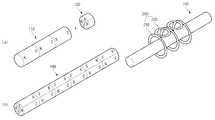
- FIG. 2Ais a view illustrating a first shaft portion and a second shaft portion of an actuator according to the present invention
- FIG. 2Bis a view illustrating a main shaft of an actuator according to the present invention.
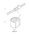
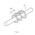
- FIG. 3is a view illustrating a first coil and a second coil coupled to a main shaft of an actuator according to the present invention.
- FIGS. 2A to 3show an actuator according to the present invention.
- FIGS. 2A and 2Bare views illustrating a first shaft portion, a second shaft portion, and a main shaft of the actuator according to the present invention
- FIG. 3is a view illustrating a first coil and a second coil coupled to a main shaft of the actuator according to the present invention.
- the actuator according to the present inventionincludes, as shown in FIGS. 2 and 3 , a main shaft 100 having a first shaft portion 110 and a second shaft portion 120 to generate a magnetic field in a omnidirection (i.e., the magnetic field generated and projected is in all directions). Additionally, a coil 200 is wound around an outer peripheral surface of the main shaft 100 and has a first coil 210 and a second coil 220 , in which a rotational driving function and a linear driving function can be performed with a single unit.
- the coil 200is wound around the main shaft 100 which has an associated magnetic field.
- the main shaft 100includes the first shaft portion 110 for generating a magnetic field in a straight direction, and a second shaft portion 120 for generating a magnetic field in a rotational direction.
- a permanent magnet for generating a magnetic field in all directionsis formed (i.e., an omnidirectional magnetic field).
- the coil 200is formed in a ring or circular shape, and is positioned on the outer peripheral surface of the main shaft 100 .
- the coil 200includes the first coil 210 and the second coil 220 .
- the first coil 210receives the outer peripheral surface of the main shaft 100 in a longitudinal direction
- the second coil 220is interposed between the first coils 210 which receive the main shaft 100 therein.
- the coil 200 including the first coil 210 and the second coil 220is positioned on the outer peripheral surface of the main shaft 100 including the first shaft portion 110 and the second portion shaft 120 to generate the magnetic field in all directions.
- the main shaft 100is inserted into the first coils 210 in the longitudinal direction in such a way that the main shaft can be linearly moved, and the second coil 220 is interposed between the first coils 210 receiving the main shaft 100 in such a way that the second coil can be rotated.
- the actuator according to the present inventioncan perform the linear movement and the rotational movement with a single unit to minimize the amount of space which the unit takes up, and to reduce errors which can occur due to the coupling of an actuator for linear movement and an actuator for rotational movement in the related art.
- the actuatorincludes the main shaft embodying as a single unit the first shaft portion for generating the magnetic field in the straight direction, and the second shaft portion for generating the magnetic field in the rotational direction, and the coil wound around the outer peripheral surface of the main shaft. Accordingly, the actuator can perform the rotational driving function and the linear driving function via the single unit to improve the positional accuracy and provide spatial efficiency, thereby improving the merchantable quality of the actuator.
Landscapes
- Engineering & Computer Science (AREA)
- Power Engineering (AREA)
- Physics & Mathematics (AREA)
- Chemical & Material Sciences (AREA)
- Combustion & Propulsion (AREA)
- Electromagnetism (AREA)
- Linear Motors (AREA)
- Reciprocating, Oscillating Or Vibrating Motors (AREA)
Abstract
Description
Claims (2)
Applications Claiming Priority (2)
| Application Number | Priority Date | Filing Date | Title |
|---|---|---|---|
| KR1020100114124AKR20120052809A (en) | 2010-11-16 | 2010-11-16 | Actuator |
| KR10-2010-0114124 | 2010-11-16 |
Publications (2)
| Publication Number | Publication Date |
|---|---|
| US20120119592A1 US20120119592A1 (en) | 2012-05-17 |
| US8546981B2true US8546981B2 (en) | 2013-10-01 |
Family
ID=46047132
Family Applications (1)
| Application Number | Title | Priority Date | Filing Date |
|---|---|---|---|
| US13/172,396Active2031-08-30US8546981B2 (en) | 2010-11-16 | 2011-06-29 | Actuator |
Country Status (3)
| Country | Link |
|---|---|
| US (1) | US8546981B2 (en) |
| KR (1) | KR20120052809A (en) |
| CN (1) | CN102468737A (en) |
Families Citing this family (1)
| Publication number | Priority date | Publication date | Assignee | Title |
|---|---|---|---|---|
| CN106849568B (en)* | 2017-02-24 | 2024-02-27 | 上海交通大学 | Controllable rotary feeding system and control method |
Citations (6)
| Publication number | Priority date | Publication date | Assignee | Title |
|---|---|---|---|---|
| US4340261A (en)* | 1978-04-26 | 1982-07-20 | Teldix Gmbh | Magnetic bearing arrangement |
| KR19990019875U (en) | 1997-11-21 | 1999-06-15 | 박문규 | Magnet structure of DC motor |
| KR20000024065A (en) | 2000-01-18 | 2000-05-06 | 윤인선 | A subsidiary actuating apparatus of motor rotor |
| US20010043016A1 (en)* | 2000-05-20 | 2001-11-22 | Chun Jang Sung | Linear motor |
| KR20050098139A (en) | 2004-04-06 | 2005-10-11 | 엘지전자 주식회사 | Apparatus for alternating optical pick-up actuator |
| WO2008107273A1 (en) | 2007-02-27 | 2008-09-12 | Schneider Electric Industries Sas | Hybrid electromagnetic actuator |
Family Cites Families (2)
| Publication number | Priority date | Publication date | Assignee | Title |
|---|---|---|---|---|
| KR100395546B1 (en)* | 2000-07-22 | 2003-08-25 | 미래산업 주식회사 | Motor of Revolving and Linear Type |
| JP4218413B2 (en)* | 2003-05-16 | 2009-02-04 | パナソニック電工株式会社 | Linear actuator for vibration and rolling drive and electric toothbrush using the same |
- 2010
- 2010-11-16KRKR1020100114124Apatent/KR20120052809A/ennot_activeCeased
- 2011
- 2011-06-29USUS13/172,396patent/US8546981B2/enactiveActive
- 2011-08-12CNCN2011102655184Apatent/CN102468737A/enactivePending
Patent Citations (7)
| Publication number | Priority date | Publication date | Assignee | Title |
|---|---|---|---|---|
| US4340261A (en)* | 1978-04-26 | 1982-07-20 | Teldix Gmbh | Magnetic bearing arrangement |
| KR19990019875U (en) | 1997-11-21 | 1999-06-15 | 박문규 | Magnet structure of DC motor |
| KR20000024065A (en) | 2000-01-18 | 2000-05-06 | 윤인선 | A subsidiary actuating apparatus of motor rotor |
| US20010043016A1 (en)* | 2000-05-20 | 2001-11-22 | Chun Jang Sung | Linear motor |
| KR20010106540A (en) | 2000-05-20 | 2001-12-07 | 정문술 | Linear Electric Motor of Rotational and Linear Movement Type |
| KR20050098139A (en) | 2004-04-06 | 2005-10-11 | 엘지전자 주식회사 | Apparatus for alternating optical pick-up actuator |
| WO2008107273A1 (en) | 2007-02-27 | 2008-09-12 | Schneider Electric Industries Sas | Hybrid electromagnetic actuator |
Also Published As
| Publication number | Publication date |
|---|---|
| KR20120052809A (en) | 2012-05-24 |
| US20120119592A1 (en) | 2012-05-17 |
| CN102468737A (en) | 2012-05-23 |
Similar Documents
| Publication | Publication Date | Title |
|---|---|---|
| KR101475555B1 (en) | Actuator | |
| KR102426462B1 (en) | 2-axis integrated motor | |
| KR101819005B1 (en) | Motor | |
| KR101904446B1 (en) | Linear motor unit | |
| JP5920637B2 (en) | Rotating electrical machine rotor | |
| US10141823B2 (en) | Motor, gimbal, and mechanical arm having the same | |
| KR101133718B1 (en) | Self-control type robot arm joint motor having auto power-off function | |
| KR101194909B1 (en) | Dual coil bobbin and spherical motor having the same | |
| JP2018054489A (en) | Encoder device, drive device, stage device, robot device, and encoder device mounting method | |
| US8546981B2 (en) | Actuator | |
| JP2016025700A (en) | Magnetic screw actuator | |
| CN104113181B (en) | A kind of composite excitation switch flux linear motor for axial feed | |
| US10103593B2 (en) | Linear motor | |
| JP6710055B2 (en) | Scale integrated linear motor and linear motion unit equipped with the linear motor | |
| JP2005218203A (en) | Actuator and bonding apparatus | |
| JP2014017999A (en) | Motor and hybrid structure for construction equipment | |
| CN102371589B (en) | Magnetic controlled robotic arm joint brake with power-off self-locking function | |
| JP5533751B2 (en) | Positioning device | |
| JP5055412B2 (en) | Magnetically controlled manipulating arm joint actuator with auto-lock function at power failure | |
| JP5821277B2 (en) | Actuator | |
| CN204271858U (en) | A rotary linear permanent magnet motor | |
| JP6387234B2 (en) | Linear motor | |
| JP2019187163A (en) | Two-axis integrated motor and actuator | |
| JP2012191817A (en) | Electromagnetic actuator | |
| KR20200079355A (en) | Motor |
Legal Events
| Date | Code | Title | Description |
|---|---|---|---|
| AS | Assignment | Owner name:HYUNDAI MOTOR COMPANY, KOREA, REPUBLIC OF Free format text:ASSIGNMENT OF ASSIGNORS INTEREST;ASSIGNOR:LEE, KYUNG MIN;REEL/FRAME:026523/0149 Effective date:20110513 | |
| STCF | Information on status: patent grant | Free format text:PATENTED CASE | |
| FEPP | Fee payment procedure | Free format text:PAYOR NUMBER ASSIGNED (ORIGINAL EVENT CODE: ASPN); ENTITY STATUS OF PATENT OWNER: LARGE ENTITY | |
| FEPP | Fee payment procedure | Free format text:PAYER NUMBER DE-ASSIGNED (ORIGINAL EVENT CODE: RMPN); ENTITY STATUS OF PATENT OWNER: LARGE ENTITY Free format text:PAYOR NUMBER ASSIGNED (ORIGINAL EVENT CODE: ASPN); ENTITY STATUS OF PATENT OWNER: LARGE ENTITY | |
| FPAY | Fee payment | Year of fee payment:4 | |
| MAFP | Maintenance fee payment | Free format text:PAYMENT OF MAINTENANCE FEE, 8TH YEAR, LARGE ENTITY (ORIGINAL EVENT CODE: M1552); ENTITY STATUS OF PATENT OWNER: LARGE ENTITY Year of fee payment:8 | |
| MAFP | Maintenance fee payment | Free format text:PAYMENT OF MAINTENANCE FEE, 12TH YEAR, LARGE ENTITY (ORIGINAL EVENT CODE: M1553); ENTITY STATUS OF PATENT OWNER: LARGE ENTITY Year of fee payment:12 |