US8545568B2 - Method of using instruments and interbody spinal implants to enhance distraction - Google Patents
Method of using instruments and interbody spinal implants to enhance distractionDownload PDFInfo
- Publication number
- US8545568B2 US8545568B2US13/480,761US201213480761AUS8545568B2US 8545568 B2US8545568 B2US 8545568B2US 201213480761 AUS201213480761 AUS 201213480761AUS 8545568 B2US8545568 B2US 8545568B2
- Authority
- US
- United States
- Prior art keywords
- implant
- spinal implant
- disc space
- bone
- anterior
- Prior art date
- Legal status (The legal status is an assumption and is not a legal conclusion. Google has not performed a legal analysis and makes no representation as to the accuracy of the status listed.)
- Expired - Lifetime
Links
Images


Classifications
- A—HUMAN NECESSITIES
- A61—MEDICAL OR VETERINARY SCIENCE; HYGIENE
- A61F—FILTERS IMPLANTABLE INTO BLOOD VESSELS; PROSTHESES; DEVICES PROVIDING PATENCY TO, OR PREVENTING COLLAPSING OF, TUBULAR STRUCTURES OF THE BODY, e.g. STENTS; ORTHOPAEDIC, NURSING OR CONTRACEPTIVE DEVICES; FOMENTATION; TREATMENT OR PROTECTION OF EYES OR EARS; BANDAGES, DRESSINGS OR ABSORBENT PADS; FIRST-AID KITS
- A61F2/00—Filters implantable into blood vessels; Prostheses, i.e. artificial substitutes or replacements for parts of the body; Appliances for connecting them with the body; Devices providing patency to, or preventing collapsing of, tubular structures of the body, e.g. stents
- A61F2/02—Prostheses implantable into the body
- A61F2/30—Joints
- A61F2/44—Joints for the spine, e.g. vertebrae, spinal discs
- A61F2/4455—Joints for the spine, e.g. vertebrae, spinal discs for the fusion of spinal bodies, e.g. intervertebral fusion of adjacent spinal bodies, e.g. fusion cages
- A61F2/4465—Joints for the spine, e.g. vertebrae, spinal discs for the fusion of spinal bodies, e.g. intervertebral fusion of adjacent spinal bodies, e.g. fusion cages having a circular or kidney shaped cross-section substantially perpendicular to the axis of the spine
- A—HUMAN NECESSITIES
- A61—MEDICAL OR VETERINARY SCIENCE; HYGIENE
- A61F—FILTERS IMPLANTABLE INTO BLOOD VESSELS; PROSTHESES; DEVICES PROVIDING PATENCY TO, OR PREVENTING COLLAPSING OF, TUBULAR STRUCTURES OF THE BODY, e.g. STENTS; ORTHOPAEDIC, NURSING OR CONTRACEPTIVE DEVICES; FOMENTATION; TREATMENT OR PROTECTION OF EYES OR EARS; BANDAGES, DRESSINGS OR ABSORBENT PADS; FIRST-AID KITS
- A61F2/00—Filters implantable into blood vessels; Prostheses, i.e. artificial substitutes or replacements for parts of the body; Appliances for connecting them with the body; Devices providing patency to, or preventing collapsing of, tubular structures of the body, e.g. stents
- A61F2/02—Prostheses implantable into the body
- A61F2/30—Joints
- A61F2/46—Special tools for implanting artificial joints
- A61F2/4603—Special tools for implanting artificial joints for insertion or extraction of endoprosthetic joints or of accessories thereof
- A61F2/4611—Special tools for implanting artificial joints for insertion or extraction of endoprosthetic joints or of accessories thereof of spinal prostheses
- A—HUMAN NECESSITIES
- A61—MEDICAL OR VETERINARY SCIENCE; HYGIENE
- A61B—DIAGNOSIS; SURGERY; IDENTIFICATION
- A61B17/00—Surgical instruments, devices or methods
- A61B17/56—Surgical instruments or methods for treatment of bones or joints; Devices specially adapted therefor
- A61B17/58—Surgical instruments or methods for treatment of bones or joints; Devices specially adapted therefor for osteosynthesis, e.g. bone plates, screws or setting implements
- A61B17/88—Osteosynthesis instruments; Methods or means for implanting or extracting internal or external fixation devices
- A61B17/92—Impactors or extractors, e.g. for removing intramedullary devices
- A61B2017/922—Devices for impaction, impact element
- A—HUMAN NECESSITIES
- A61—MEDICAL OR VETERINARY SCIENCE; HYGIENE
- A61F—FILTERS IMPLANTABLE INTO BLOOD VESSELS; PROSTHESES; DEVICES PROVIDING PATENCY TO, OR PREVENTING COLLAPSING OF, TUBULAR STRUCTURES OF THE BODY, e.g. STENTS; ORTHOPAEDIC, NURSING OR CONTRACEPTIVE DEVICES; FOMENTATION; TREATMENT OR PROTECTION OF EYES OR EARS; BANDAGES, DRESSINGS OR ABSORBENT PADS; FIRST-AID KITS
- A61F2/00—Filters implantable into blood vessels; Prostheses, i.e. artificial substitutes or replacements for parts of the body; Appliances for connecting them with the body; Devices providing patency to, or preventing collapsing of, tubular structures of the body, e.g. stents
- A61F2/02—Prostheses implantable into the body
- A61F2/30—Joints
- A61F2/3094—Designing or manufacturing processes
- A61F2/30965—Reinforcing the prosthesis by embedding particles or fibres during moulding or dipping
- A—HUMAN NECESSITIES
- A61—MEDICAL OR VETERINARY SCIENCE; HYGIENE
- A61F—FILTERS IMPLANTABLE INTO BLOOD VESSELS; PROSTHESES; DEVICES PROVIDING PATENCY TO, OR PREVENTING COLLAPSING OF, TUBULAR STRUCTURES OF THE BODY, e.g. STENTS; ORTHOPAEDIC, NURSING OR CONTRACEPTIVE DEVICES; FOMENTATION; TREATMENT OR PROTECTION OF EYES OR EARS; BANDAGES, DRESSINGS OR ABSORBENT PADS; FIRST-AID KITS
- A61F2/00—Filters implantable into blood vessels; Prostheses, i.e. artificial substitutes or replacements for parts of the body; Appliances for connecting them with the body; Devices providing patency to, or preventing collapsing of, tubular structures of the body, e.g. stents
- A61F2/02—Prostheses implantable into the body
- A61F2/28—Bones
- A61F2002/2817—Bone stimulation by chemical reactions or by osteogenic or biological products for enhancing ossification, e.g. by bone morphogenetic or morphogenic proteins [BMP] or by transforming growth factors [TGF]
- A—HUMAN NECESSITIES
- A61—MEDICAL OR VETERINARY SCIENCE; HYGIENE
- A61F—FILTERS IMPLANTABLE INTO BLOOD VESSELS; PROSTHESES; DEVICES PROVIDING PATENCY TO, OR PREVENTING COLLAPSING OF, TUBULAR STRUCTURES OF THE BODY, e.g. STENTS; ORTHOPAEDIC, NURSING OR CONTRACEPTIVE DEVICES; FOMENTATION; TREATMENT OR PROTECTION OF EYES OR EARS; BANDAGES, DRESSINGS OR ABSORBENT PADS; FIRST-AID KITS
- A61F2/00—Filters implantable into blood vessels; Prostheses, i.e. artificial substitutes or replacements for parts of the body; Appliances for connecting them with the body; Devices providing patency to, or preventing collapsing of, tubular structures of the body, e.g. stents
- A61F2/02—Prostheses implantable into the body
- A61F2/28—Bones
- A61F2002/2835—Bone graft implants for filling a bony defect or an endoprosthesis cavity, e.g. by synthetic material or biological material
- A—HUMAN NECESSITIES
- A61—MEDICAL OR VETERINARY SCIENCE; HYGIENE
- A61F—FILTERS IMPLANTABLE INTO BLOOD VESSELS; PROSTHESES; DEVICES PROVIDING PATENCY TO, OR PREVENTING COLLAPSING OF, TUBULAR STRUCTURES OF THE BODY, e.g. STENTS; ORTHOPAEDIC, NURSING OR CONTRACEPTIVE DEVICES; FOMENTATION; TREATMENT OR PROTECTION OF EYES OR EARS; BANDAGES, DRESSINGS OR ABSORBENT PADS; FIRST-AID KITS
- A61F2/00—Filters implantable into blood vessels; Prostheses, i.e. artificial substitutes or replacements for parts of the body; Appliances for connecting them with the body; Devices providing patency to, or preventing collapsing of, tubular structures of the body, e.g. stents
- A61F2/02—Prostheses implantable into the body
- A61F2/30—Joints
- A61F2002/30001—Additional features of subject-matter classified in A61F2/28, A61F2/30 and subgroups thereof
- A61F2002/30003—Material related properties of the prosthesis or of a coating on the prosthesis
- A61F2002/30004—Material related properties of the prosthesis or of a coating on the prosthesis the prosthesis being made from materials having different values of a given property at different locations within the same prosthesis
- A61F2002/30014—Material related properties of the prosthesis or of a coating on the prosthesis the prosthesis being made from materials having different values of a given property at different locations within the same prosthesis differing in elasticity, stiffness or compressibility
- A—HUMAN NECESSITIES
- A61—MEDICAL OR VETERINARY SCIENCE; HYGIENE
- A61F—FILTERS IMPLANTABLE INTO BLOOD VESSELS; PROSTHESES; DEVICES PROVIDING PATENCY TO, OR PREVENTING COLLAPSING OF, TUBULAR STRUCTURES OF THE BODY, e.g. STENTS; ORTHOPAEDIC, NURSING OR CONTRACEPTIVE DEVICES; FOMENTATION; TREATMENT OR PROTECTION OF EYES OR EARS; BANDAGES, DRESSINGS OR ABSORBENT PADS; FIRST-AID KITS
- A61F2/00—Filters implantable into blood vessels; Prostheses, i.e. artificial substitutes or replacements for parts of the body; Appliances for connecting them with the body; Devices providing patency to, or preventing collapsing of, tubular structures of the body, e.g. stents
- A61F2/02—Prostheses implantable into the body
- A61F2/30—Joints
- A61F2002/30001—Additional features of subject-matter classified in A61F2/28, A61F2/30 and subgroups thereof
- A61F2002/30108—Shapes
- A61F2002/3011—Cross-sections or two-dimensional shapes
- A61F2002/30112—Rounded shapes, e.g. with rounded corners
- A61F2002/30133—Rounded shapes, e.g. with rounded corners kidney-shaped or bean-shaped
- A—HUMAN NECESSITIES
- A61—MEDICAL OR VETERINARY SCIENCE; HYGIENE
- A61F—FILTERS IMPLANTABLE INTO BLOOD VESSELS; PROSTHESES; DEVICES PROVIDING PATENCY TO, OR PREVENTING COLLAPSING OF, TUBULAR STRUCTURES OF THE BODY, e.g. STENTS; ORTHOPAEDIC, NURSING OR CONTRACEPTIVE DEVICES; FOMENTATION; TREATMENT OR PROTECTION OF EYES OR EARS; BANDAGES, DRESSINGS OR ABSORBENT PADS; FIRST-AID KITS
- A61F2/00—Filters implantable into blood vessels; Prostheses, i.e. artificial substitutes or replacements for parts of the body; Appliances for connecting them with the body; Devices providing patency to, or preventing collapsing of, tubular structures of the body, e.g. stents
- A61F2/02—Prostheses implantable into the body
- A61F2/30—Joints
- A61F2002/30001—Additional features of subject-matter classified in A61F2/28, A61F2/30 and subgroups thereof
- A61F2002/30316—The prosthesis having different structural features at different locations within the same prosthesis; Connections between prosthetic parts; Special structural features of bone or joint prostheses not otherwise provided for
- A61F2002/30329—Connections or couplings between prosthetic parts, e.g. between modular parts; Connecting elements
- A61F2002/30331—Connections or couplings between prosthetic parts, e.g. between modular parts; Connecting elements made by longitudinally pushing a protrusion into a complementarily-shaped recess, e.g. held by friction fit
- A61F2002/30354—Cylindrically-shaped protrusion and recess, e.g. cylinder of circular basis
- A61F2002/30357—Stepped cylinders, i.e. having discrete diameter changes
- A—HUMAN NECESSITIES
- A61—MEDICAL OR VETERINARY SCIENCE; HYGIENE
- A61F—FILTERS IMPLANTABLE INTO BLOOD VESSELS; PROSTHESES; DEVICES PROVIDING PATENCY TO, OR PREVENTING COLLAPSING OF, TUBULAR STRUCTURES OF THE BODY, e.g. STENTS; ORTHOPAEDIC, NURSING OR CONTRACEPTIVE DEVICES; FOMENTATION; TREATMENT OR PROTECTION OF EYES OR EARS; BANDAGES, DRESSINGS OR ABSORBENT PADS; FIRST-AID KITS
- A61F2/00—Filters implantable into blood vessels; Prostheses, i.e. artificial substitutes or replacements for parts of the body; Appliances for connecting them with the body; Devices providing patency to, or preventing collapsing of, tubular structures of the body, e.g. stents
- A61F2/02—Prostheses implantable into the body
- A61F2/30—Joints
- A61F2002/30001—Additional features of subject-matter classified in A61F2/28, A61F2/30 and subgroups thereof
- A61F2002/30316—The prosthesis having different structural features at different locations within the same prosthesis; Connections between prosthetic parts; Special structural features of bone or joint prostheses not otherwise provided for
- A61F2002/30329—Connections or couplings between prosthetic parts, e.g. between modular parts; Connecting elements
- A61F2002/30405—Connections or couplings between prosthetic parts, e.g. between modular parts; Connecting elements made by screwing complementary threads machined on the parts themselves
- A—HUMAN NECESSITIES
- A61—MEDICAL OR VETERINARY SCIENCE; HYGIENE
- A61F—FILTERS IMPLANTABLE INTO BLOOD VESSELS; PROSTHESES; DEVICES PROVIDING PATENCY TO, OR PREVENTING COLLAPSING OF, TUBULAR STRUCTURES OF THE BODY, e.g. STENTS; ORTHOPAEDIC, NURSING OR CONTRACEPTIVE DEVICES; FOMENTATION; TREATMENT OR PROTECTION OF EYES OR EARS; BANDAGES, DRESSINGS OR ABSORBENT PADS; FIRST-AID KITS
- A61F2/00—Filters implantable into blood vessels; Prostheses, i.e. artificial substitutes or replacements for parts of the body; Appliances for connecting them with the body; Devices providing patency to, or preventing collapsing of, tubular structures of the body, e.g. stents
- A61F2/02—Prostheses implantable into the body
- A61F2/30—Joints
- A61F2002/30001—Additional features of subject-matter classified in A61F2/28, A61F2/30 and subgroups thereof
- A61F2002/30316—The prosthesis having different structural features at different locations within the same prosthesis; Connections between prosthetic parts; Special structural features of bone or joint prostheses not otherwise provided for
- A61F2002/30329—Connections or couplings between prosthetic parts, e.g. between modular parts; Connecting elements
- A61F2002/30476—Connections or couplings between prosthetic parts, e.g. between modular parts; Connecting elements locked by an additional locking mechanism
- A61F2002/30485—Connections or couplings between prosthetic parts, e.g. between modular parts; Connecting elements locked by an additional locking mechanism plastically deformable
- A—HUMAN NECESSITIES
- A61—MEDICAL OR VETERINARY SCIENCE; HYGIENE
- A61F—FILTERS IMPLANTABLE INTO BLOOD VESSELS; PROSTHESES; DEVICES PROVIDING PATENCY TO, OR PREVENTING COLLAPSING OF, TUBULAR STRUCTURES OF THE BODY, e.g. STENTS; ORTHOPAEDIC, NURSING OR CONTRACEPTIVE DEVICES; FOMENTATION; TREATMENT OR PROTECTION OF EYES OR EARS; BANDAGES, DRESSINGS OR ABSORBENT PADS; FIRST-AID KITS
- A61F2/00—Filters implantable into blood vessels; Prostheses, i.e. artificial substitutes or replacements for parts of the body; Appliances for connecting them with the body; Devices providing patency to, or preventing collapsing of, tubular structures of the body, e.g. stents
- A61F2/02—Prostheses implantable into the body
- A61F2/30—Joints
- A61F2002/30001—Additional features of subject-matter classified in A61F2/28, A61F2/30 and subgroups thereof
- A61F2002/30316—The prosthesis having different structural features at different locations within the same prosthesis; Connections between prosthetic parts; Special structural features of bone or joint prostheses not otherwise provided for
- A61F2002/30535—Special structural features of bone or joint prostheses not otherwise provided for
- A61F2002/30593—Special structural features of bone or joint prostheses not otherwise provided for hollow
- A—HUMAN NECESSITIES
- A61—MEDICAL OR VETERINARY SCIENCE; HYGIENE
- A61F—FILTERS IMPLANTABLE INTO BLOOD VESSELS; PROSTHESES; DEVICES PROVIDING PATENCY TO, OR PREVENTING COLLAPSING OF, TUBULAR STRUCTURES OF THE BODY, e.g. STENTS; ORTHOPAEDIC, NURSING OR CONTRACEPTIVE DEVICES; FOMENTATION; TREATMENT OR PROTECTION OF EYES OR EARS; BANDAGES, DRESSINGS OR ABSORBENT PADS; FIRST-AID KITS
- A61F2/00—Filters implantable into blood vessels; Prostheses, i.e. artificial substitutes or replacements for parts of the body; Appliances for connecting them with the body; Devices providing patency to, or preventing collapsing of, tubular structures of the body, e.g. stents
- A61F2/02—Prostheses implantable into the body
- A61F2/30—Joints
- A61F2002/30001—Additional features of subject-matter classified in A61F2/28, A61F2/30 and subgroups thereof
- A61F2002/30316—The prosthesis having different structural features at different locations within the same prosthesis; Connections between prosthetic parts; Special structural features of bone or joint prostheses not otherwise provided for
- A61F2002/30535—Special structural features of bone or joint prostheses not otherwise provided for
- A61F2002/30604—Special structural features of bone or joint prostheses not otherwise provided for modular
- A—HUMAN NECESSITIES
- A61—MEDICAL OR VETERINARY SCIENCE; HYGIENE
- A61F—FILTERS IMPLANTABLE INTO BLOOD VESSELS; PROSTHESES; DEVICES PROVIDING PATENCY TO, OR PREVENTING COLLAPSING OF, TUBULAR STRUCTURES OF THE BODY, e.g. STENTS; ORTHOPAEDIC, NURSING OR CONTRACEPTIVE DEVICES; FOMENTATION; TREATMENT OR PROTECTION OF EYES OR EARS; BANDAGES, DRESSINGS OR ABSORBENT PADS; FIRST-AID KITS
- A61F2/00—Filters implantable into blood vessels; Prostheses, i.e. artificial substitutes or replacements for parts of the body; Appliances for connecting them with the body; Devices providing patency to, or preventing collapsing of, tubular structures of the body, e.g. stents
- A61F2/02—Prostheses implantable into the body
- A61F2/30—Joints
- A61F2/30767—Special external or bone-contacting surface, e.g. coating for improving bone ingrowth
- A61F2/30771—Special external or bone-contacting surface, e.g. coating for improving bone ingrowth applied in original prostheses, e.g. holes or grooves
- A61F2002/30772—Apertures or holes, e.g. of circular cross section
- A61F2002/30784—Plurality of holes
- A61F2002/30785—Plurality of holes parallel
- A—HUMAN NECESSITIES
- A61—MEDICAL OR VETERINARY SCIENCE; HYGIENE
- A61F—FILTERS IMPLANTABLE INTO BLOOD VESSELS; PROSTHESES; DEVICES PROVIDING PATENCY TO, OR PREVENTING COLLAPSING OF, TUBULAR STRUCTURES OF THE BODY, e.g. STENTS; ORTHOPAEDIC, NURSING OR CONTRACEPTIVE DEVICES; FOMENTATION; TREATMENT OR PROTECTION OF EYES OR EARS; BANDAGES, DRESSINGS OR ABSORBENT PADS; FIRST-AID KITS
- A61F2/00—Filters implantable into blood vessels; Prostheses, i.e. artificial substitutes or replacements for parts of the body; Appliances for connecting them with the body; Devices providing patency to, or preventing collapsing of, tubular structures of the body, e.g. stents
- A61F2/02—Prostheses implantable into the body
- A61F2/30—Joints
- A61F2/30767—Special external or bone-contacting surface, e.g. coating for improving bone ingrowth
- A61F2/30771—Special external or bone-contacting surface, e.g. coating for improving bone ingrowth applied in original prostheses, e.g. holes or grooves
- A61F2002/30836—Special external or bone-contacting surface, e.g. coating for improving bone ingrowth applied in original prostheses, e.g. holes or grooves knurled
- A—HUMAN NECESSITIES
- A61—MEDICAL OR VETERINARY SCIENCE; HYGIENE
- A61F—FILTERS IMPLANTABLE INTO BLOOD VESSELS; PROSTHESES; DEVICES PROVIDING PATENCY TO, OR PREVENTING COLLAPSING OF, TUBULAR STRUCTURES OF THE BODY, e.g. STENTS; ORTHOPAEDIC, NURSING OR CONTRACEPTIVE DEVICES; FOMENTATION; TREATMENT OR PROTECTION OF EYES OR EARS; BANDAGES, DRESSINGS OR ABSORBENT PADS; FIRST-AID KITS
- A61F2/00—Filters implantable into blood vessels; Prostheses, i.e. artificial substitutes or replacements for parts of the body; Appliances for connecting them with the body; Devices providing patency to, or preventing collapsing of, tubular structures of the body, e.g. stents
- A61F2/02—Prostheses implantable into the body
- A61F2/30—Joints
- A61F2/30767—Special external or bone-contacting surface, e.g. coating for improving bone ingrowth
- A61F2/30771—Special external or bone-contacting surface, e.g. coating for improving bone ingrowth applied in original prostheses, e.g. holes or grooves
- A61F2002/30838—Microstructures
- A—HUMAN NECESSITIES
- A61—MEDICAL OR VETERINARY SCIENCE; HYGIENE
- A61F—FILTERS IMPLANTABLE INTO BLOOD VESSELS; PROSTHESES; DEVICES PROVIDING PATENCY TO, OR PREVENTING COLLAPSING OF, TUBULAR STRUCTURES OF THE BODY, e.g. STENTS; ORTHOPAEDIC, NURSING OR CONTRACEPTIVE DEVICES; FOMENTATION; TREATMENT OR PROTECTION OF EYES OR EARS; BANDAGES, DRESSINGS OR ABSORBENT PADS; FIRST-AID KITS
- A61F2/00—Filters implantable into blood vessels; Prostheses, i.e. artificial substitutes or replacements for parts of the body; Appliances for connecting them with the body; Devices providing patency to, or preventing collapsing of, tubular structures of the body, e.g. stents
- A61F2/02—Prostheses implantable into the body
- A61F2/30—Joints
- A61F2/30767—Special external or bone-contacting surface, e.g. coating for improving bone ingrowth
- A61F2/30771—Special external or bone-contacting surface, e.g. coating for improving bone ingrowth applied in original prostheses, e.g. holes or grooves
- A61F2002/30878—Special external or bone-contacting surface, e.g. coating for improving bone ingrowth applied in original prostheses, e.g. holes or grooves with non-sharp protrusions, for instance contacting the bone for anchoring, e.g. keels, pegs, pins, posts, shanks, stems, struts
- A61F2002/30891—Plurality of protrusions
- A61F2002/30892—Plurality of protrusions parallel
- A—HUMAN NECESSITIES
- A61—MEDICAL OR VETERINARY SCIENCE; HYGIENE
- A61F—FILTERS IMPLANTABLE INTO BLOOD VESSELS; PROSTHESES; DEVICES PROVIDING PATENCY TO, OR PREVENTING COLLAPSING OF, TUBULAR STRUCTURES OF THE BODY, e.g. STENTS; ORTHOPAEDIC, NURSING OR CONTRACEPTIVE DEVICES; FOMENTATION; TREATMENT OR PROTECTION OF EYES OR EARS; BANDAGES, DRESSINGS OR ABSORBENT PADS; FIRST-AID KITS
- A61F2/00—Filters implantable into blood vessels; Prostheses, i.e. artificial substitutes or replacements for parts of the body; Appliances for connecting them with the body; Devices providing patency to, or preventing collapsing of, tubular structures of the body, e.g. stents
- A61F2/02—Prostheses implantable into the body
- A61F2/30—Joints
- A61F2/30767—Special external or bone-contacting surface, e.g. coating for improving bone ingrowth
- A61F2002/30906—Special external or bone-contacting surface, e.g. coating for improving bone ingrowth shot- sand- or grit-blasted
- A—HUMAN NECESSITIES
- A61—MEDICAL OR VETERINARY SCIENCE; HYGIENE
- A61F—FILTERS IMPLANTABLE INTO BLOOD VESSELS; PROSTHESES; DEVICES PROVIDING PATENCY TO, OR PREVENTING COLLAPSING OF, TUBULAR STRUCTURES OF THE BODY, e.g. STENTS; ORTHOPAEDIC, NURSING OR CONTRACEPTIVE DEVICES; FOMENTATION; TREATMENT OR PROTECTION OF EYES OR EARS; BANDAGES, DRESSINGS OR ABSORBENT PADS; FIRST-AID KITS
- A61F2/00—Filters implantable into blood vessels; Prostheses, i.e. artificial substitutes or replacements for parts of the body; Appliances for connecting them with the body; Devices providing patency to, or preventing collapsing of, tubular structures of the body, e.g. stents
- A61F2/02—Prostheses implantable into the body
- A61F2/30—Joints
- A61F2/30767—Special external or bone-contacting surface, e.g. coating for improving bone ingrowth
- A61F2002/30922—Hardened surfaces
- A—HUMAN NECESSITIES
- A61—MEDICAL OR VETERINARY SCIENCE; HYGIENE
- A61F—FILTERS IMPLANTABLE INTO BLOOD VESSELS; PROSTHESES; DEVICES PROVIDING PATENCY TO, OR PREVENTING COLLAPSING OF, TUBULAR STRUCTURES OF THE BODY, e.g. STENTS; ORTHOPAEDIC, NURSING OR CONTRACEPTIVE DEVICES; FOMENTATION; TREATMENT OR PROTECTION OF EYES OR EARS; BANDAGES, DRESSINGS OR ABSORBENT PADS; FIRST-AID KITS
- A61F2/00—Filters implantable into blood vessels; Prostheses, i.e. artificial substitutes or replacements for parts of the body; Appliances for connecting them with the body; Devices providing patency to, or preventing collapsing of, tubular structures of the body, e.g. stents
- A61F2/02—Prostheses implantable into the body
- A61F2/30—Joints
- A61F2/30767—Special external or bone-contacting surface, e.g. coating for improving bone ingrowth
- A61F2002/30925—Special external or bone-contacting surface, e.g. coating for improving bone ingrowth etched
- A—HUMAN NECESSITIES
- A61—MEDICAL OR VETERINARY SCIENCE; HYGIENE
- A61F—FILTERS IMPLANTABLE INTO BLOOD VESSELS; PROSTHESES; DEVICES PROVIDING PATENCY TO, OR PREVENTING COLLAPSING OF, TUBULAR STRUCTURES OF THE BODY, e.g. STENTS; ORTHOPAEDIC, NURSING OR CONTRACEPTIVE DEVICES; FOMENTATION; TREATMENT OR PROTECTION OF EYES OR EARS; BANDAGES, DRESSINGS OR ABSORBENT PADS; FIRST-AID KITS
- A61F2/00—Filters implantable into blood vessels; Prostheses, i.e. artificial substitutes or replacements for parts of the body; Appliances for connecting them with the body; Devices providing patency to, or preventing collapsing of, tubular structures of the body, e.g. stents
- A61F2/02—Prostheses implantable into the body
- A61F2/30—Joints
- A61F2/30767—Special external or bone-contacting surface, e.g. coating for improving bone ingrowth
- A61F2002/3093—Special external or bone-contacting surface, e.g. coating for improving bone ingrowth for promoting ingrowth of bone tissue
- A—HUMAN NECESSITIES
- A61—MEDICAL OR VETERINARY SCIENCE; HYGIENE
- A61F—FILTERS IMPLANTABLE INTO BLOOD VESSELS; PROSTHESES; DEVICES PROVIDING PATENCY TO, OR PREVENTING COLLAPSING OF, TUBULAR STRUCTURES OF THE BODY, e.g. STENTS; ORTHOPAEDIC, NURSING OR CONTRACEPTIVE DEVICES; FOMENTATION; TREATMENT OR PROTECTION OF EYES OR EARS; BANDAGES, DRESSINGS OR ABSORBENT PADS; FIRST-AID KITS
- A61F2/00—Filters implantable into blood vessels; Prostheses, i.e. artificial substitutes or replacements for parts of the body; Appliances for connecting them with the body; Devices providing patency to, or preventing collapsing of, tubular structures of the body, e.g. stents
- A61F2/02—Prostheses implantable into the body
- A61F2/30—Joints
- A61F2/3094—Designing or manufacturing processes
- A61F2002/30971—Laminates, i.e. layered products
- A61F2002/30973—Two joined adjacent layers having complementary interlocking protrusions and recesses
- A—HUMAN NECESSITIES
- A61—MEDICAL OR VETERINARY SCIENCE; HYGIENE
- A61F—FILTERS IMPLANTABLE INTO BLOOD VESSELS; PROSTHESES; DEVICES PROVIDING PATENCY TO, OR PREVENTING COLLAPSING OF, TUBULAR STRUCTURES OF THE BODY, e.g. STENTS; ORTHOPAEDIC, NURSING OR CONTRACEPTIVE DEVICES; FOMENTATION; TREATMENT OR PROTECTION OF EYES OR EARS; BANDAGES, DRESSINGS OR ABSORBENT PADS; FIRST-AID KITS
- A61F2/00—Filters implantable into blood vessels; Prostheses, i.e. artificial substitutes or replacements for parts of the body; Appliances for connecting them with the body; Devices providing patency to, or preventing collapsing of, tubular structures of the body, e.g. stents
- A61F2/02—Prostheses implantable into the body
- A61F2/30—Joints
- A61F2/44—Joints for the spine, e.g. vertebrae, spinal discs
- A61F2002/448—Joints for the spine, e.g. vertebrae, spinal discs comprising multiple adjacent spinal implants within the same intervertebral space or within the same vertebra, e.g. comprising two adjacent spinal implants
- A—HUMAN NECESSITIES
- A61—MEDICAL OR VETERINARY SCIENCE; HYGIENE
- A61F—FILTERS IMPLANTABLE INTO BLOOD VESSELS; PROSTHESES; DEVICES PROVIDING PATENCY TO, OR PREVENTING COLLAPSING OF, TUBULAR STRUCTURES OF THE BODY, e.g. STENTS; ORTHOPAEDIC, NURSING OR CONTRACEPTIVE DEVICES; FOMENTATION; TREATMENT OR PROTECTION OF EYES OR EARS; BANDAGES, DRESSINGS OR ABSORBENT PADS; FIRST-AID KITS
- A61F2/00—Filters implantable into blood vessels; Prostheses, i.e. artificial substitutes or replacements for parts of the body; Appliances for connecting them with the body; Devices providing patency to, or preventing collapsing of, tubular structures of the body, e.g. stents
- A61F2/02—Prostheses implantable into the body
- A61F2/30—Joints
- A61F2/46—Special tools for implanting artificial joints
- A61F2/4603—Special tools for implanting artificial joints for insertion or extraction of endoprosthetic joints or of accessories thereof
- A61F2002/4629—Special tools for implanting artificial joints for insertion or extraction of endoprosthetic joints or of accessories thereof connected to the endoprosthesis or implant via a threaded connection
- A—HUMAN NECESSITIES
- A61—MEDICAL OR VETERINARY SCIENCE; HYGIENE
- A61F—FILTERS IMPLANTABLE INTO BLOOD VESSELS; PROSTHESES; DEVICES PROVIDING PATENCY TO, OR PREVENTING COLLAPSING OF, TUBULAR STRUCTURES OF THE BODY, e.g. STENTS; ORTHOPAEDIC, NURSING OR CONTRACEPTIVE DEVICES; FOMENTATION; TREATMENT OR PROTECTION OF EYES OR EARS; BANDAGES, DRESSINGS OR ABSORBENT PADS; FIRST-AID KITS
- A61F2310/00—Prostheses classified in A61F2/28 or A61F2/30 - A61F2/44 being constructed from or coated with a particular material
- A61F2310/00005—The prosthesis being constructed from a particular material
- A61F2310/00011—Metals or alloys
- A61F2310/00017—Iron- or Fe-based alloys, e.g. stainless steel
- A—HUMAN NECESSITIES
- A61—MEDICAL OR VETERINARY SCIENCE; HYGIENE
- A61F—FILTERS IMPLANTABLE INTO BLOOD VESSELS; PROSTHESES; DEVICES PROVIDING PATENCY TO, OR PREVENTING COLLAPSING OF, TUBULAR STRUCTURES OF THE BODY, e.g. STENTS; ORTHOPAEDIC, NURSING OR CONTRACEPTIVE DEVICES; FOMENTATION; TREATMENT OR PROTECTION OF EYES OR EARS; BANDAGES, DRESSINGS OR ABSORBENT PADS; FIRST-AID KITS
- A61F2310/00—Prostheses classified in A61F2/28 or A61F2/30 - A61F2/44 being constructed from or coated with a particular material
- A61F2310/00005—The prosthesis being constructed from a particular material
- A61F2310/00011—Metals or alloys
- A61F2310/00023—Titanium or titanium-based alloys, e.g. Ti-Ni alloys
- A—HUMAN NECESSITIES
- A61—MEDICAL OR VETERINARY SCIENCE; HYGIENE
- A61F—FILTERS IMPLANTABLE INTO BLOOD VESSELS; PROSTHESES; DEVICES PROVIDING PATENCY TO, OR PREVENTING COLLAPSING OF, TUBULAR STRUCTURES OF THE BODY, e.g. STENTS; ORTHOPAEDIC, NURSING OR CONTRACEPTIVE DEVICES; FOMENTATION; TREATMENT OR PROTECTION OF EYES OR EARS; BANDAGES, DRESSINGS OR ABSORBENT PADS; FIRST-AID KITS
- A61F2310/00—Prostheses classified in A61F2/28 or A61F2/30 - A61F2/44 being constructed from or coated with a particular material
- A61F2310/00005—The prosthesis being constructed from a particular material
- A61F2310/00179—Ceramics or ceramic-like structures
Definitions
- the present inventionrelates generally to interbody spinal implants and methods of using such implants and, more particularly, to a method of using an implant along with instruments to enhance distraction.
- the spineis a column made of vertebrae and discs.
- the vertebraeprovide the support and structure of the spine while the spinal discs, located between the vertebrae, act as cushions or “shock absorbers.” These discs also contribute to the flexibility and motion of the spinal column. Over time, the discs may become diseased or infected, may develop deformities such as tears or cracks, or may simply lose structural integrity (e.g., the discs may bulge or flatten). Impaired discs can affect the anatomical functions of the vertebrae, due to the resultant lack of proper biomechanical support, and are often associated with chronic back pain.
- Spinal fusionhas become a recognized surgical procedure for mitigating back pain by restoring biomechanical and anatomical integrity to the spine.
- Spinal fusion techniquesinvolve the removal, or partial removal, of at least one intervertebral disc and preparation of the disc space for receiving an implant by shaping the exposed vertebral endplates. An implant is then inserted between the opposing endplates.
- Spinal fusion procedurescan be achieved using a posterior or an anterior approach.
- Anterior interbody fusion proceduresgenerally have the advantages of reduced operative times and reduced blood loss. Further, anterior procedures do not interfere with the posterior anatomic structure of the lumbar spine. Anterior procedures also minimize scarring within the spinal canal while still achieving improved fusion rates, which is advantageous from a structural and biomechanical perspective. These generally preferred anterior procedures are particularly advantageous in providing improved access to the disc space, and thus correspondingly better endplate preparation.
- interbody implant systemshave been introduced to facilitate interbody fusion.
- Traditional threaded implantsinvolve at least two cylindrical bodies, each typically packed with bone graft material, surgically placed on opposite sides of the mid-sagittal plane through pre-tapped holes within the intervertebral disc space. This location is not the preferable seating position for an implant system, however, because only a relatively small portion of the vertebral endplate is contacted by these cylindrical implants. Accordingly, these implant bodies will likely contact the softer cancellous bone rather than the stronger cortical bone, or apophyseal rim, of the vertebral endplate.
- the seating of these threaded cylindrical implantsmay also compromise biomechanical integrity by reducing the area in which to distribute mechanical forces, thus increasing the apparent stress experienced by both the implant and vertebrae. Still further, a substantial risk of implant subsidence (defined as sinking or settling) into the softer cancellous bone of the vertebral body may arise from such improper seating.
- open ring-shaped cage implant systemsare generally shaped to mimic the anatomical contour of the vertebral body.
- Traditional ring-shaped cagesare generally comprised of allograft bone material, however, harvested from the human femur.
- allograft bone materialrestricts the usable size and shape of the resultant implant.
- many of these femoral ring-shaped cagesgenerally have a medial-lateral width of less than 25 mm. Therefore, these cages may not be of a sufficient size to contact the strong cortical bone, or apophyseal rim, of the vertebral endplate.
- These size-limited implant systemsmay also poorly accommodate related instrumentation such as drivers, reamers, distractors, and the like.
- these implant systemsmay lack sufficient structural integrity to withstand repeated impact and may fracture during implantation.
- other traditional non-allograft ring-shaped cage systemsmay be size-limited due to varied and complex supplemental implant instrumentation which may obstruct the disc space while requiring greater exposure of the operating space.
- These supplemental implant instrumentation systemsalso generally increase the instrument load upon the surgeon.
- the surgical procedure corresponding to an implant systemshould preserve as much vertebral endplate bone surface as possible by minimizing the amount of bone removed.
- This vertebral endplate bone surface, or subchondral boneis generally much stronger than the underlying cancellous bone.
- Preservation of the endplate bone stockensures biomechanical integrity of the endplates and minimizes the risk of implant subsidence.
- proper interbody implant designshould provide for optimal seating of the implant while utilizing the maximum amount of available supporting vertebral bone stock.
- interbody spinal implantsgenerally do not seat properly on the preferred structural bone located near the apophyseal rim of the vertebral body, which is primarily composed of preferred dense subchondral bone. Accordingly, there is a need in the art for interbody spinal implants which better utilize the structurally supportive bone of the apophyseal rim.
- the firstis aggressive end-plate removal with box-chisel types of tools to create a nice match of end-plate geometry with implant geometry.
- the end-platesare typically destroyed. Such destruction means that the load-bearing implant is pressed against soft cancellous bone and the implant tends to subside.
- the second traditional end-plate preparation methodpreserves the end-plates by just removing cartilage with curettes.
- the end-platesare concave; hence, if a flat implant is used, the implant is not very stable. Even if a convex implant is used, it is very difficult to match the implant geometry with the end-plate geometry, as the end-plate geometry varies from patient-to-patient and on the extent of disease.
- the third traditional end-plate preparation methoduses threaded fusion cages.
- the cagesare implanted by reaming out corresponding threads in the end-plates. This method also violates the structure.
- Traditional anterior spinal fusion devicescan also be difficult to implant.
- Some traditional implants with teethhave sharp edges. These edges can bind to the surrounding soft tissue during implantation, creating surgical challenges.
- secondary instrumentationis used to keep the disc space distracted during implantation.
- the use of such instrumentationmeans that the exposure needs to be large enough to accommodate the instrumentation. If there is a restriction on the exposure size, then the maximum size of the implant available for use is correspondingly limited.
- the need for secondary instrumentation for distraction during implantationalso adds an additional step or two in surgery.
- secondary instrumentationmay sometimes over-distract the annulus, reducing the ability of the annulus to compress a relatively undersized implant. The compression provided by the annulus on the implant is important to maintain the initial stability of the implant.
- anterior spinal surgerythere are traditionally three trajectories of implants: anterior, antero-lateral, and lateral.
- Each approachhas its advantages and drawbacks. Sometimes the choice of the approach is dictated by surgeon preference, and sometimes it is dictated by patient anatomy and biomechanics.
- a typical traditional implanthas design features to accommodate only one or two of these approaches in a single implant, restricting intra-operative flexibility.
- Typical devicesare made of PEEK or cadaver bone. Materials such as PEEK or cadaver bone do not have the structural strength to withstand impact loads required during implantation and may fracture during implantation.
- PEEKis an abbreviation for polyetherether-ketone, a high-performance engineering thermoplastic with excellent chemical and fatigue resistance plus thermal stability. With a maximum continuous working temperature of 480° F., PEEK offers superior mechanical properties. Superior chemical resistance has allowed PEEK to work effectively as a metal replacement in harsh environments. PEEK grades offer chemical and water resistance similar to PPS (polyphenylene sulfide), but can operate at higher temperatures. PEEK materials are inert to all common solvents and resist a wide range of organic and inorganic liquids. Thus, for hostile environments, PEEK is a high-strength alternative to fluoropolymers.
- cadaver bonehas several drawbacks.
- the shapes and sizes of the implantsare restricted by the bone from which the implant is machined.
- Cadaver bonecarries with it the risk of disease transmission and raises shelf-life and storage issues.
- cadaver bonehas insufficient mechanical strength for clinical application.
- Subsidence of the implantis a complex issue and has been attributed to many factors. Some of these factors include aggressive removal of the end-plate; an implant stiffness significantly greater than the vertebral bone; smaller sized implants which tend to seat in the center of the disc space, against the weakest region of the end-plates; and implants with sharp edges which can cause localized stress fractures in the end-plates at the point of contact.
- the most common solution to the problem of subsidenceis to choose a less stiff implant material. This is why PEEK and cadaver bone have become the most common materials for spinal fusion implants. PEEK is softer than cortical bone, but harder than cancellous bone.
- Cadaver bone implantsare restricted in their size by the bone from which they are machined. Their wall thickness also has to be great to create sufficient structural integrity for their desired clinical application. These design restrictions do not leave much room for filling the bone graft material into cortical bone implants. The exposure-driven limitations on implant size narrow the room left inside the implant geometry for bone grafting even for metal implants. Such room is further reduced in the case of PEEK implants because their wall thickness needs to be greater as compared to metal implants due to structural strength needs.
- the bone graft packed inside the implantneeds to be loaded mechanically.
- the stiffness of the implant materialis much greater than the adjacent vertebral bone and takes up a majority of the mechanical loads, “shielding” the bone graft material from becoming mechanically loaded.
- the most common solutionis to choose a less stiff implant material. Again, this is why PEEK and cadaver bone have become the most common materials for spinal fusion implants. As noted above, although harder than cancellous bone, PEEK is softer than cortical bone.
- the typical fusion implantis not able to incorporate with the vertebral bone, even years after implantation. Such inability persists despite the use of a variety of different materials to construct the implants.
- cadaver boneis resorbable and will be replaced by new bone once it resorbs.
- Hedrocelis a composite material composed of carbon and tantalum, an inert metal, that has been used as a material for spinal fusion implants. Hedrocel is designed to allow bone in-growth into the implant.
- PEEKhas been reported to become surrounded by fibrous tissue which precludes it from incorporating with surrounding bone.
- bio-active materialswhich can incorporate into bone. The application of such bio-active materials has been limited, however, for several reasons, including biocompatibility, structural strength, and lack of regulatory approval.
- PEEKis radiolucent. Traditional implants made of PEEK need to have radiographic markers embedded into the implants so that implant position can be tracked on an X-ray. Cadaver bone has some radiopacity and does not interfere with radiographic assessment as much as metal implants.
- the present inventionis directed to interbody spinal implants and to methods of using such implants.
- the implantscan be inserted, using methods of the present invention, from a variety of vantages, including anterior, antero-lateral, and lateral implantation.
- Certain embodiments of the present inventionprovide an anatomically shaped spinal implant for improved seating in the disc space, particularly in the medial-lateral aspect of the disc space, and improved utilization of the vertebral apophyseal rim.
- Certain embodiments of the present inventionfurther have a highly radiused posterior portion and sides which allow for ease of implantation. Thus, the posterior portion may have a generally blunt nosed profile.
- Certain embodimentsalso allow for improved visualization of the disc space during surgical procedures while minimizing exposure of the operating space.
- Certain aspects of the inventionreduce the need for additional instrumentation—such as chisels, reamers, or other tools—to prepare the vertebral endplate, thus minimizing the instrument load upon the surgeon.
- interbody implantare substantially hollow and have a generally oval-shaped transverse cross-sectional area.
- substantially hollowmeans at least about 33% of the interior volume of the interbody spinal implant is vacant.
- Further embodiments of the present inventioninclude a body having a top surface, a bottom surface, opposing lateral sides, and opposing anterior and posterior portions.
- the implantincludes at least one aperture that extends the entire height of the body. Thus, the aperture extends from the top surface to the bottom surface.
- the implantmay further include at least one aperture that extends the entire transverse length of the implant body.
- the substantially hollow portionmay be filled with cancellous autograft bone, allograft bone, demineralized bone matrix (DBM), porous synthetic bone graft substitute, bone morphogenic protein (BMP), or combinations of those materials.
- the implantfurther includes a roughened surface topography on at least a portion of its top surface, its bottom surface, or both surfaces.
- the anterior portion, or trailing edge, of the implantis preferably generally greater in height than the opposing posterior portion, or leading edge. In other words, the trailing edge is taller than the leading edge.
- the posterior portion and lateral sidesmay also be generally smooth and highly radiused, thus allowing for easier implantation into the disc space.
- the posterior portionmay have a blunt nosed profile.
- the anterior portion of the implantmay preferably be configured to engage a delivery device, a driver, or other surgical tools.
- the anterior portionmay also be substantially flat.
- the present inventionprovides an interbody spinal implant including a body having a top surface, a bottom surface, opposing lateral sides, opposing anterior and posterior portions, a substantially hollow center, and a single vertical aperture.
- the single vertical apertureextends from the top surface to the bottom surface, has a size and shape predetermined to maximize the surface area of the top surface and the bottom surface available proximate the anterior and posterior portions while maximizing both radiographic visualization and access to the substantially hollow center, and defines a transverse rim.
- the bodymay be non-metallic and may form one component of a composite implant; the other component is a metal plate disposed on at least one of the top and bottom surfaces of the body.
- the present inventionprovides a method of using an interbody spinal implant by implanting the spinal implant into a patient in need of the spinal implant.
- the methodincludes accessing the disc space of the patient and locating the center of the disc space.
- the disc spaceis incised by making a window in the annulus of the disc space for insertion of the spinal implant.
- the endplatesare cleaned of all cartilage and the disc structure, which is encapsulated by the annulus, is removed while avoiding damage to the endplate structure of the vertebrae.
- a size-specific raspis selected and the disc space is cleared of all soft tissue and cartilage.
- the disc spaceis distracted by sequentially expanding it with distractors of progressively increasing heights.
- a spinal implant having a pre-determined size sufficient to balance frictional fit and elongation of the annulusis selected and seated in the disc space.
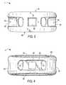
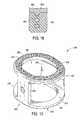
- FIG. 1shows a perspective view of a first embodiment of the interbody spinal implant having a generally oval shape and roughened surface topography on the top surface;
- FIG. 2depicts a top view of the first embodiment of the interbody spinal implant
- FIG. 3depicts an anterior view of the first embodiment of the interbody spinal implant
- FIG. 4depicts a posterior view of the first embodiment of the interbody spinal implant
- FIG. 5Adepicts a first post-operative radiograph showing visualization of an embodiment of the interbody spinal implant
- FIG. 5Bdepicts a second post-operative radiograph showing visualization of an embodiment of the interbody spinal implant
- FIG. 5Cdepicts a third post-operative radiograph showing visualization of an embodiment of the interbody spinal implant
- FIG. 6shows an exemplary surgical tool (implant holder) to be used with certain embodiments of the interbody spinal implant
- FIG. 7shows an exemplary distractor used during certain methods of implantation
- FIG. 8shows an exemplary rasp used during certain methods of implantation
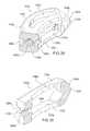
- FIG. 9shows a perspective view from the front of another embodiment of the interbody spinal implant according to the present invention.
- FIG. 10shows a perspective view from the rear of the embodiment of the interbody spinal implant illustrated in FIG. 9 ;
- FIG. 11is a top view of the interbody spinal implant illustrated in FIGS. 9 and 10 ;
- FIG. 12shows a perspective view from the rear, like FIG. 10 , of the interbody spinal implant illustrated in FIGS. 9-11 highlighting an alternative transverse aperture;
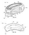
- FIG. 13shows a perspective view from the front of yet another embodiment of the interbody spinal implant according to the present invention.
- FIG. 14is a top view of the interbody spinal implant illustrated in FIG. 13 ;
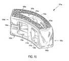
- FIG. 15shows a perspective view from the rear of the embodiment of the interbody spinal implant illustrated in FIG. 13 highlighting an alternative transverse aperture
- FIG. 16shows a perspective view from the side of one component of a composite embodiment of the interbody spinal implant
- FIG. 17is a top view of the composite embodiment of the interbody spinal implant illustrated in FIG. 16 with the components attached;
- FIG. 18shows an exemplary mechanism by which the two components of the composite embodiment of the interbody spinal implant illustrated in FIGS. 16 and 17 may be attached;
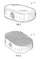
- FIG. 19shows a perspective view of a final embodiment of the interbody spinal implant having a generally oval shape and being especially well adapted for use in a cervical spine surgical procedure;
- FIG. 20shows a perspective view of the final implant having a generally box shape
- FIG. 21shows a cross-sectional view of the interbody spinal implant having the shape of the first embodiment illustrated in FIG. 1 ;
- FIG. 22shows a top view of the interbody spinal implant illustrated in FIG. 21 ;
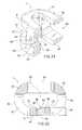
- FIG. 23shows a portion of an instrument adapted to engage with and manipulate the implant illustrated in FIGS. 21 and 22 ;
- FIG. 24highlights the impact head of the instrument shown in FIG. 23 ;
- FIG. 25shows an instrument adapted to engage with and manipulate the implant according to another embodiment of the present invention.
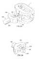
- FIG. 26shows a slap impacting hammer as used in connection with an instrument adapted to engage with and manipulate the implant according to another embodiment of the present invention
- FIG. 27illustrates the connection between the slap impacting hammer and the handle of the instrument shown in FIG. 26 ;
- FIG. 28shows a top view of an alternative embodiment of the interbody spinal implant shown in FIGS. 9 and 10 , highlighting a threaded instrument connection;
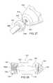
- FIG. 29shows a perspective view of an alternative embodiment of the interbody spinal implant shown in FIGS. 13-15 , highlighting a threaded instrument connection;
- FIG. 30is a perspective view, in partial cross section, showing example dimensions for various features of the implant shown in FIG. 29 ;
- FIG. 31illustrates an alternative embodiment of the instrument used to engage the implants, according to the present invention, each having both a threaded opening and implant holding features;
- FIG. 32illustrates the combination of (a) an embodiment of the instrument having a threaded projection with (b) an embodiment of the rasp having a threaded opening.
- Certain embodiments of the present inventionmay be especially suited for placement between adjacent human vertebral bodies.
- the implants of the present inventionmay be used in procedures such as Anterior Lumbar Interbody Fusion (ALIF), Posterior Lumbar Interbody Fusion (PLIF), Transforaminal Lumbar Interbody Fusion (TLIF), and cervical fusion. Certain embodiments do not extend beyond the outer dimensions of the vertebral bodies.
- Interbody spinal implantsallow for improved seating over the apophyseal rim of the vertebral body. Still further, interbody spinal implants, as now taught, better utilize this vital surface area over which fusion may occur and may better bear the considerable biomechanical loads presented through the spinal column with minimal interference with other anatomical or neurological spinal structures. Even further, interbody spinal implants, according to certain aspects of the present invention, allow for improved visualization of implant seating and fusion assessment. Interbody spinal implants, as now taught, may also facilitate osteointegration with the surrounding living bone.
- Anterior interbody spinal implants in accordance with certain aspects of the present inventioncan be preferably made of a durable material such as stainless steel, stainless steel alloy, titanium, or titanium alloy, but can also be made of other durable materials such as, but not limited to, polymeric, ceramic, and composite materials.
- a durable materialsuch as stainless steel, stainless steel alloy, titanium, or titanium alloy
- other durable materialssuch as, but not limited to, polymeric, ceramic, and composite materials.
- certain embodiments of the present inventionmay be comprised of a biocompatible, polymeric matrix reinforced with bioactive fillers, fibers, or both.
- Certain embodiments of the present inventionmay be comprised of urethane dimethacrylate (DUDMA)/tri-ethylene glycol dimethacrylate (TEDGMA) blended resin and a plurality of fillers and fibers including bioactive fillers and E-glass fibers.
- Durable materialsmay also consist of any number of pure metals, metal alloys, or both.
- Titanium and its alloysare generally preferred for certain embodiments of the present invention due to their acceptable, and desirable, strength and biocompatibility.
- certain embodiments of the present interbody spinal implantmay have improved structural integrity and may better resist fracture during implantation by impact. Interbody spinal implants, as now taught, may therefore be used as a distractor during implantation.
- FIG. 1shows a perspective view of a first embodiment of the interbody spinal implant 1 especially well adapted for use in an ALIF procedure.
- the interbody spinal implant 1includes a body having a top surface 10 , a bottom surface 20 , opposing lateral sides 30 , and opposing anterior 40 and posterior 50 portions.
- One or both of the top surface 10 and the bottom surface 20has a roughened topography 80 . Distinguish the roughened topography 80 , however, from the disadvantageous teeth provided on the surfaces of some conventional devices.
- the interbody spinal implant 1are substantially hollow and have a generally oval-shaped transverse cross-sectional area with smooth, rounded, or both smooth and rounded lateral sides and posterior-lateral corners.
- substantially hollowmeans at least about 33% of the interior volume of the interbody spinal implant 1 is vacant.
- the implant 1includes at least one vertical aperture 60 that extends the entire height of the implant body. As illustrated in the top view of FIG. 2 , the vertical aperture 60 further defines a transverse rim 100 having a greater posterior portion thickness 55 than an anterior portion thickness 45 .
- the opposing lateral sides 30 and the anterior portion 40have a rim thickness of about 5 mm, while the posterior portion 50 has a rim thickness of about 7 mm.
- the rim posterior portion thickness 55may allow for better stress sharing between the implant 1 and the adjacent vertebral endplates and helps to compensate for the weaker posterior endplate bone.
- the transverse rim 100has a generally large surface area and contacts the vertebral endplate. The transverse rim 100 may act to better distribute contact stresses upon the implant 1 , and hence minimize the risk of subsidence while maximizing contact with the apophyseal supportive bone.
- the transverse rim 100it is also possible for the transverse rim 100 to have a substantially constant thickness (i.e., for the anterior portion thickness 45 to be substantially the same as the posterior portion thickness 55 ) or, in fact, for the posterior portion 50 to have a rim thickness less than that of the opposing lateral sides 30 and the anterior portion 40 .
- implant fixationmay depend, at least in part, on the attachment and proliferation of osteoblasts and like-functioning cells upon the implant surface. Still further, it appears that these cells attach more readily to relatively rough surfaces rather than smooth surfaces. In this manner, a surface may be bioactive due to its ability to facilitate cellular attachment and osteointegration.
- the surface roughened topography 80may better promote the osteointegration of certain embodiments of the present invention.
- the surface roughened topography 80may also better grip the vertebral endplate surfaces and inhibit implant migration upon placement and seating.
- the implant 1further includes the roughened topography 80 on at least a portion of its top and bottom surfaces 10 , 20 for gripping adjacent bone and inhibiting migration of the implant 1 .
- the roughened topography 80may be obtained through a variety of techniques including, without limitation, chemical etching, shot peening, plasma etching, laser etching, or abrasive blasting (such as sand or grit blasting).
- the interbody spinal implant 1may be comprised of titanium, or a titanium alloy, having the surface roughened topography 80 .
- the surfaces of the implant 1are preferably bioactive.
- the roughened topography 80is obtained via the repetitive masking and chemical or electrochemical milling processes described in U.S. Pat. No. 5,258,098; U.S. Pat. No. 5,507,815; U.S. Pat. No. 5,922,029; and U.S. Pat. No. 6,193,762.
- the surfaceis prepared through an etching process which utilizes the random application of a maskant and subsequent etching of the metallic substrate in areas unprotected by the maskant. This etching process is repeated a number of times as necessitated by the amount and nature of the irregularities required for any particular application.
- Control of the strength of the etchant material, the temperature at which the etching process takes place, and the time allotted for the etching processallow fine control over the resulting surface produced by the process.
- the number of repetitions of the etching processcan also be used to control the surface features.
- an etchant mixture of nitric acid (HNO 3 ) and hydrofluoric (HF) acidmay be repeatedly applied to a titanium surface to produce an average etch depth of about 0.53 mm.
- Interbody spinal implantsin accordance with preferred embodiments of the present invention, may be comprised of titanium, or a titanium alloy, having an average surface roughness of about 100 ⁇ m. Surface roughness may be measured using a laser profilometer or other standard instrumentation.
- chemical modification of the titanium implant surfacescan be achieved using HF and a combination of hydrochloric acid and sulfuric acid (HCl/H 2 SO 4 ).
- HFhydrochloric acid and sulfuric acid
- the first exposureis to HF and the second is to HCl/H 2 SO 4 .
- Chemical acid etching alone of the titanium implant surfacehas the potential to greatly enhance osteointegration without adding particulate matter (e.g., hydroxyapatite) or embedding surface contaminants (e.g., grit particles).
- Certain embodiments of the implant 1are generally shaped to reduce the risk of subsidence, and improve stability, by maximizing contact with the apophyseal rim of the vertebral endplates.
- Embodimentsmay be provided in a variety of anatomical footprints having a medial-lateral width ranging from about 32 mm to about 44 mm.
- Interbody spinal implantsas now taught, generally do not require extensive supplemental or obstructive implant instrumentation to maintain the prepared disc space during implantation.
- the interbody spinal implant 1 and associated implantation methodsallow for larger sized implants as compared with the size-limited interbody spinal implants known in the art. This advantage allows for greater medial-lateral width and correspondingly greater contact with the apophyseal rim.
- FIG. 3depicts an anterior view
- FIG. 4depicts a posterior view, of an embodiment of the interbody spinal implant 1 .
- the implant 1has an opening 90 in the anterior portion 40 .
- the posterior portion 50has a similarly shaped opening 90 .
- only the anterior portion 40has the opening 90 while the posterior portion 50 has an alternative opening 92 (which may have a size and shape different from the opening 90 ).
- the opening 90has a number of functions. One function is to facilitate manipulation of the implant 1 by the caretaker.
- the caretakermay insert a surgical tool into the opening 90 and, through the engagement between the surgical tool and the opening 90 , manipulate the implant 1 .
- the opening 90may be threaded to enhance the engagement.
- FIG. 6shows an exemplary surgical tool, specifically an implant holder 2 , to be used with certain embodiments of the interbody spinal implant 1 .
- the implant holder 2has a handle 4 that the caretaker can easily grasp and an end 6 that engages the opening 90 .
- the end 6may be threaded to engage corresponding threads in the opening 90 .
- the size and shape of the opening 90can be varied to accommodate a variety of tools.
- the opening 90is substantially square as illustrated in FIGS. 1 , 3 , and 4 , other sizes and shapes are feasible.
- the implant 1may further include at least one transverse aperture 70 that extends the entire transverse length of the implant body. As shown in FIGS. 5A-5C , these transverse apertures 70 may provide improved visibility of the implant 1 during surgical procedures to ensure proper implant placement and seating, and may also improve post-operative assessment of implant fusion. Still further, the substantially hollow area defined by the implant 1 may be filled with cancellous autograft bone, allograft bone, DBM, porous synthetic bone graft substitute, BMP, or combinations of these materials (collectively, bone graft materials), to facilitate the formation of a solid fusion column within the spine of a patient.
- the anterior portion 40 , or trailing edge, of the implant 1is preferably generally greater in height than the opposing posterior portion 50 . Accordingly, the implant 1 may have a lordotic angle to facilitate sagittal alignment. The implant 1 may better compensate, therefore, for the generally less supportive bone found in the posterior regions of the vertebral endplate.
- the posterior portion 50 of the interbody implant 1preferably including the posterior-lateral corners, may also be highly radiused, thus allowing for ease of implantation into the disc space. Thus, the posterior portion 50 may have a generally blunt nosed profile.
- the anterior portion 40 of the implant 1may also preferably be configured to engage a delivery device, driver, or other surgical tool (and, therefore, may have an opening 90 ).
- the anterior portion 40 of the implant 1is substantially flat.
- the anterior portion 40provides a face that can receive impact from a tool, such as a surgical hammer, to force the implant 1 into position.
- the implant 1has a sharp edge 8 where the anterior portion 40 meets the top surface 10 , where the anterior portion 40 meets the bottom surface 20 , or in both locations.
- the sharp edge or edges 8function to resist pullout of the implant 1 once it is inserted into position.
- Certain embodiments of the present inventionare particularly suited for use during interbody spinal implant procedures (or vertebral body replacement procedures) and may act as a final distractor during implantation, thus minimizing the instrument load upon the surgeon.
- the spinemay first be exposed via an anterior approach and the center of the disc space identified.
- the disc spaceis then initially prepared for implant insertion by removing vertebral cartilage.
- Soft tissue and residual cartilagemay then also be removed from the vertebral endplates.
- Vertebral distractionmay be performed using trials of various-sized embodiments of the interbody spinal implant 1 .
- the determinatively sized interbody implant 1may then be inserted in the prepared disc space for final placement.
- the distraction procedure and final insertionmay also be performed under fluoroscopic guidance.
- the substantially hollow area within the implant bodymay optionally be filled, at least partially, with bone fusion-enabling materials such as, without limitation, cancellous autograft bone, allograft bone, DBM, porous synthetic bone graft substitute, BMP, or combinations of those materials.
- bone fusion-enabling materialmay be delivered to the interior of the interbody spinal implant 1 using a delivery device mated with the opening 90 in the anterior portion 40 of the implant 1 .
- Interbody spinal implants 1are generally larger than those currently known in the art, and therefore have a correspondingly larger hollow area which may deliver larger volumes of fusion-enabling bone graft material.
- the bone graft materialmay be delivered such that it fills the full volume, or less than the full volume, of the implant interior and surrounding disc space appropriately.
- FIG. 1shows a perspective view of one embodiment of the present invention, the interbody spinal implant 1 , which is especially well adapted for use in an ALIF procedure.
- Other embodiments of the present inventionare better suited for PLIF, TLIF, or cervical fusion procedures.
- FIGS. 9 and 10show perspective views, from the front and rear, respectively, of an embodiment of an interbody spinal implant 101 especially well adapted for use in a PLIF procedure.
- the interbody spinal implant 101includes a body having a top surface 110 , a bottom surface 120 , opposing lateral sides 130 , and opposing anterior 140 and posterior 150 portions.
- One or both of the top surface 110 and the bottom surface 120has a roughened topography 180 for gripping adjacent bone and inhibiting migration of the implant 101 .
- the interbody spinal implant 101are substantially hollow and have a generally rectangular shape with smooth, rounded, or both smooth and rounded lateral sides and anterior-lateral corners.
- the anterior portion 140may have a tapered nose 142 to facilitate insertion of the implant 101 .
- the implant 101has chamfers 106 at the corners of its posterior portion 150 . The chamfers 106 prevent the implant 101 from catching upon insertion, risking potential damage such as severed nerves, while still permitting the implant 101 to have a sharp edge 108 .
- the posterior portion 150 of the implant 101is substantially flat.
- the posterior portion 150provides a face that can receive impact from a tool, such as a surgical hammer, to force the implant 101 into position.
- the implant 101has a sharp edge 108 between the chamfers 106 where the posterior portion 150 meets the top surface 110 , where the posterior portion 150 meets the bottom surface 120 , or in both locations.
- the sharp edge or edges 108function to resist pullout of the implant 101 once it is inserted into position.
- the implant 101includes at least one vertical aperture 160 that extends the entire height of the implant body. As illustrated in the top view of FIG. 11 , the vertical aperture 160 further defines a transverse rim 200 .
- the size and shape of the vertical aperture 160are carefully chosen to achieve a preferable design trade off for the particular application envisioned for the implant 101 . Specifically, the vertical aperture 160 seeks to maximize the surface area of the top surface 110 and the bottom surface 120 available proximate the anterior 140 and posterior 150 portions while maximizing both radiographic visualization and access to the bone graft material toward the center of the top 110 and bottom 120 surfaces.
- the size and shape of the vertical aperture 160are predetermined by the application. By “predetermined” is meant determined beforehand, so that the predetermined size and shape are determined, i.e., chosen or at least known, before the implant 101 is selected for insertion.
- the width of the implant 101 between the two lateral sides 130is approximately 9 mm.
- the shape of the vertical aperture 160approximates, in cross section, that of an American football.
- the center of the vertical aperture 160which defines the maximum width of the vertical aperture 160 , is about 5 mm.
- the rim thickness 200 on either side of the vertical aperture 160 adjacent the center of the vertical aperture 160is about 2 mm.
- the vertical aperture 160tapers from its center to its ends along a longitudinal distance of about 7.75 mm (thus, the total length of the vertical aperture 160 is about 15.5 mm). This shape leaves intact much of the rim thickness 200 in the areas around the ends of the vertical aperture 160 . These areas may allow for better stress sharing between the implant 101 and the adjacent vertebral endplates. Thus, the transverse rim 200 has a generally large surface area and contacts the vertebral endplate.
- the implant 101has an opening 190 in the posterior portion 150 .
- the opening 190has a number of functions. One function is to facilitate manipulation of the implant 101 by the caretaker.
- the caretakermay insert a surgical tool ( FIG. 6 shows an exemplary surgical tool, the implant holder 2 ) into the opening 190 and, through the engagement between the surgical tool and the opening 190 , manipulate the implant 101 .
- the opening 190may be threaded to enhance the engagement.
- the implant 101may also have an Implant Holding Feature (IHF) 194 instead of or in addition to the opening 190 .
- IHFImplant Holding Feature
- the IHF 194is located proximate the opening 190 in the posterior portion 150 .
- the IHF 194is a U-shaped notch.
- the IHF 194has a number of functions, one of which is to facilitate manipulation of the implant 101 by the caretaker. Other functions of the opening 190 and the IHF 194 are to increase visibility of the implant 101 during surgical procedures and to enhance engagement between bone graft material and adjacent bone.
- the implant 101may further include at least one transverse aperture 170 .
- the size and shape of the transverse aperture 170are carefully chosen (and predetermined) to achieve a preferable design trade off for the particular application envisioned for the implant 101 .
- the transverse aperture 170should have minimal dimensions to maximize the strength and structural integrity of the implant 101 .
- the transverse aperture 70should have maximum dimensions to (a) improve the visibility of the implant 101 during surgical procedures to ensure proper implant placement and seating, and to improve post-operative assessment of implant fusion, and (b) to facilitate engagement between bone graft material and adjacent bone.
- the substantially hollow area defined by the implant 101may be filled with bone graft materials to facilitate the formation of a solid fusion column within the spine of a patient.
- the transverse aperture 170extends the entire transverse length of the implant body and nearly the entire height of the implant body. Thus, the size and shape of the transverse aperture 170 approach the maximum possible dimensions for the transverse aperture 170 .
- FIG. 12shows a perspective view from the rear of the interbody spinal implant 101 . FIG. 12 highlights, however, an alternative transverse aperture 170 .
- the transverse aperture 170is broken into two, separate sections by an intermediate wall 172 .
- the dimensions of the transverse aperture 170 shown in FIG. 12are much smaller than those for the transverse aperture 170 shown in FIG. 10 .
- the section of the transverse aperture 170 proximate the IHF 194is substantially rectangular in shape; the other section of the transverse aperture 170 has the shape of a curved arch.
- Other shapes and dimensionsare suitable for the transverse aperture 170 .
- all edges of the transverse aperture 170may be rounded, smooth, or both.
- the intermediate wall 172may be made of the same material as the remainder of the implant 101 (e.g., metal), or it may be made of another material (e.g., PEEK) to form a composite implant 101 .
- the intermediate wall 172may offer one or more of several advantages, including reinforcement of the implant 101 and improved bone graft containment.
- FIGS. 9-12The embodiment of the present invention illustrated in FIGS. 9-12 is especially well suited for a PLIF surgical procedure.
- TLIF surgeryis done through the posterior (rear) part of the spine and is essentially like an extended PLIF procedure.
- the TLIF procedurewas developed in response to some of the technical problems encountered with a PLIF procedure.
- the main difference between the two spine fusion proceduresis that the TLIF approach to the disc space is expanded by removing one entire facet joint; a PLIF procedure is usually done on both sides by only taking a portion of each of the paired facet joints.
- the anterior approachin most cases still provides the best visualization, most surface area for healing, and the best reduction of any of the approaches to the disc space.
- These advantagesmust be weighed, however, against the increased morbidity (e.g., unwanted aftereffects and postoperative discomfort) of a second incision.
- Probably the biggest determinate in how the disc space is approachedis the comfort level that the spine surgeon has with an anterior approach for the spine fusion surgery. Not all spine surgeons are comfortable with operating around the great vessels (aorta and vena cava) or have access to a skilled vascular surgeon to help them with the approach. Therefore, choosing one of the posterior approaches for the spine fusion surgery is often a more practical solution.
- FIGS. 13-15The embodiment of the present invention illustrated in FIGS. 13-15 is especially well suited when the spine surgeon elects a TLIF procedure. Many of the features of the implant 101 a illustrated in FIGS. 13-15 are the same as those of the implant 101 illustrated in FIGS. 9-12 . Therefore, these features are given the same reference numbers, with the addition of the letter “a,” and are not described further.
- the implant 101 ahas a curved shape.
- the chamfers 106 and sharp edges 108 of the implant 101are replaced by curves or rounded edges for the implant 101 a .
- the TLIF procedureoften permits use of a larger implant 101 a which, in turn, may affect the size and shape of the predetermined vertical aperture 160 a.
- FIG. 14illustrates a top view of the implant 101 a .
- the substantially constant 9 mm width of the transverse rim 200 of the implant 101is replaced with a larger, curved transverse rim 200 a .
- the width of the transverse rim 200 ais 9 mm in the regions adjacent the anterior 140 a and posterior 150 a portions. That width gradually increases to 11 mm, however, near the center of the transverse rim 200 a .
- the additional real estate provided by the transverse rim 200 aallows the shape of the vertical aperture 160 a to change, in cross section, from approximating a football to approximating a boomerang. Maintaining the thickness of the transverse rim 200 a on either side of the vertical aperture 160 a adjacent the center of the vertical aperture 160 a at about 2 mm, similar to the dimensions of the implant 101 , the center of the vertical aperture 160 a , which defines the maximum width of the vertical aperture 160 a , is increased (from 5 mm for the implant 101 ) to about 7 mm.
- the implant 101 amay also have a lordotic angle to facilitate alignment. As illustrated in FIG. 14 , the lateral side 130 a depicted at the top of the implant 101 a is preferably generally greater in height than the opposing lateral side 130 a . Therefore, the implant 101 a may better compensate for the generally less supportive bone found in certain regions of the vertebral endplate.
- the transverse aperture 170 aextends the entire transverse length of the implant body and nearly the entire height of the implant body.
- FIG. 15highlights an alternative transverse aperture 170 a .
- the transverse aperture 170 ais broken into two, separate sections by an intermediate wall 172 a .
- the dimensions of the transverse aperture 170 a shown in FIG. 15are much smaller than those for the transverse aperture 170 a shown in FIG. 13 .
- the two sections of the alternative transverse aperture 170 aare each illustrated as substantially rectangular in shape and extending nearly the entire height of the implant body; other sizes and shapes are possible for one or both sections of the alternative transverse aperture 170 a.
- the intermediate wall 172 amay be made of the same material as the remainder of the implant 101 a (e.g., metal), or it may be made of another material (e.g., PEEK) to form a composite implant 101 a . It is also possible to extend the intermediate wall 172 a , whether made of metal, PEEK, ultra-high molecular weight polyethylene (UHMWPE), or another material, to eliminate entirely the transverse aperture 170 a . Given the reinforcement function of the intermediate wall 172 a , the length of the vertical aperture 160 a can be extended (as shown in FIG. 15 ) beyond the top surface 110 a and into the anterior portion 140 a of the implant 101 a.
- UHMWPEultra-high molecular weight polyethylene
- top surface 110 a of the implant 101 a shown in FIG. 14differs from the top surface 110 a of the implant 101 a shown in FIGS. 13 and 15 in that the former does not include the roughened topography 180 a of the latter.
- This differencepermits the implant 101 a , at least for certain applications, to be made entirely of a non-metal material. Suitable materials of construction for the implant 101 a of such a design (which would not be a composite) include PEEK, hedrocel, UHMWPE, other radiolucent soft plastics, and additional materials as would be known to an artisan.
- FIG. 16shows a perspective view from the side of one component of the composite implant 101 a : an all plastic body 152 .
- the body 152may preferably be injection molded.
- PEEKis a suitable material for the body 152 .
- a second component of the composite implant 101 ais provided: one or more metal strips or plates 162 .
- the plates 162may be provided on the top surface 110 a , on the bottom surface 120 a , or on both surfaces 110 a and 120 a.
- the composite implant 101 acombines the benefits of two, separate components: a body 152 and a plate 162 .
- the composite structure of implant 101 aadvantageously permits the engineering designer of the implant 101 a to balance the mechanical characteristics of the overall implant 101 a . This allows the implant 101 a to achieve the best balance, for example, of strength, resistance to subsidence, and stress transfer to bone graft.
- the implant 101 acan be inserted with minimal surgical modification. This combination of size and minimal surgical modification is advantageous.
- the body 152 of the composite implant 101 ahas a recessed upper surface 154 .
- the recessed upper surface 154is recessed below the top surface 110 a of the composite implant 101 a by an amount corresponding to the thickness of the plate 162 that will be installed over the recessed upper surface 154 to create a substantially flat top surface 110 a .
- FIG. 17is a top view of the composite interbody spinal implant 101 a with the plate 162 installed.
- the plate 162has a roughened topography 180 a .
- a corresponding second plate 162may be installed on the bottom surface 120 a of the composite implant 101 a.
- FIGS. 16 and 18One connection mechanism is illustrated in FIGS. 16 and 18 .
- FIG. 16shows that a plurality of holes 156 are provided in the recessed upper surface 154 of the body 152 .
- the holes 156receive a corresponding plurality of legs 164 on the plate 162 .
- the legs 164are positioned on the plate 162 so that, when the plate 162 is installed over the recessed upper surface 154 of the body 152 , each of the legs 164 engages one of the holes 156 .
- the legs 164are integral with the remainder of the plate 162 .
- integralis meant a single piece or a single unitary part that is complete by itself without additional pieces, i.e., the part is of one monolithic piece formed as a unit with another part.
- the legs 164may be configured to prevent them from exiting the holes 156 .
- the legs 164have a toothed periphery. If the plate 162 is metal and the body 152 is plastic, the body 152 may be injection molded around the legs 164 of the plate 162 . In some applications, for example were the body 152 and the plate 162 both made of metal, it may be possible to provide corresponding threads on the legs 164 and holes 156 .
- FIGS. 19 and 20illustrate the interbody spinal implant 201 .
- the discsare usually not very large.
- the space available for the nervesis also not that great, however, which means that even a small cervical disc herniation may impinge on the nerve and cause significant pain.
- the implant 201is generally smaller in size than the other implant embodiments.
- the lower mechanical load requirements imposed by the cervical applicationtypically render a composite implant unnecessary. Therefore, the implant 201 is generally made entirely of metal (e.g., titanium) and devoid of other materials (e.g., PEEK).
- the implant 201includes a body having a top surface 210 , a bottom surface 220 , opposing lateral sides 230 , and opposing anterior 240 and posterior 250 portions.
- One or both of the top surface 210 and the bottom surface 220has a roughened topography 280 for gripping adjacent bone and inhibiting migration of the implant 201 .
- the implant 201is substantially hollow and has a generally oval shape with smooth, rounded, or both smooth and rounded edges.
- the implant 201includes at least one vertical aperture 260 that extends the entire height of the implant body.
- the vertical aperture 260further defines a transverse rim 300 .
- the size and shape of the vertical aperture 260are carefully chosen to achieve a preferable design trade off for the particular application envisioned for the implant 201 .
- the vertical aperture 260seeks to maximize the surface area of the top surface 210 and the bottom surface 220 , to allow for better stress sharing between the implant 201 and the adjacent vertebral endplates, while maximizing access to the bone graft material provided within the implant 201 .
- the size and shape of the vertical aperture 260are predetermined by the application.
- the implant 201has an opening 290 in the posterior portion 250 .
- the opening 290has a number of functions. One function is to facilitate manipulation of the implant 201 by the caretaker.
- the caretakermay insert a surgical tool ( FIG. 6 shows an exemplary surgical tool, the implant holder 2 ) into the opening 290 and, through the engagement between the surgical tool and the opening 290 , manipulate the implant 201 .
- the opening 290may be threaded to enhance the engagement.
- the implant 201may further include at least one transverse aperture 270 .
- the size and shape of the transverse aperture 270are carefully chosen (and predetermined) to achieve a preferable design trade off for the particular application envisioned for the implant 201 .
- the transverse aperture 270may extend the entire transverse length of the implant body and nearly the entire height of the implant body.
- the size and shape of the transverse aperture 270approach the maximum possible dimensions for the transverse aperture 270 .
- the implant 201may be provided with a solid rear wall 242 .
- the rear wall 242extends the entire width of the implant body and nearly the entire height of the implant body. Thus, the rear wall 242 essentially closes the anterior portion 240 of the implant 201 .
- the rear wall 242may offer one or more of several advantages, including reinforcement of the implant 201 and improved bone graft containment. In the cervical application, it may be important to prevent bone graft material from entering the spinal canal.
- the implant 201may have a generally box shape which gives the implant 201 increased cortical bone coverage.
- the implant 201 shown in FIG. 20has a curved transverse rim 300 in the area of the anterior portion 240 .
- the shape of the posterior portion 250 of the implant 201is substantially flat, however, and the shape of the transverse rim 300 in the area of the posterior portion 250 is substantially square.
- the posterior portion 250provides a face that can receive impact from a tool, such as a surgical hammer, to force the implant 201 into position.
- the implant 201may also have a lordotic angle to facilitate alignment. As illustrated in FIGS. 19 and 20 , the anterior portion 240 is preferably generally greater in height than the posterior portion 250 . Therefore, the implant 201 may better compensate for the generally less supportive bone found in certain regions of the vertebral endplate. As an example, four degrees of lordosis may be built into the implant 201 to help restore balance to the spine.
- Certain embodiments of the implant 1 , 101 , 101 a , 101 b (see below), and 201are generally shaped (i.e., made wide) to maximize contact with the apophyseal rim of the vertebral endplates. They are designed to be impacted between the endplates, with fixation to the endplates created by an interference fit and annular tension.
- the implants 1 , 101 , 101 a , 101 b , and 201are shaped and sized to spare the vertebral endplates and leave intact the hoop stress of the endplates.
- a wide range of sizesare possible to capture the apophyseal rim, along with a broad width of the peripheral rim, especially in the posterior region. It is expected that such designs will lead to reduced subsidence. As much as seven degrees of lordosis (or more) may be built into the implants 1 , 101 , 101 a , 101 b , and 201 to help restore cervical balance.
- endplate-sparing spinal implant 1 , 101 , 101 a , 101 b , and 201seats in the disc space against the apophyseal rim, it should still allow for deflection of the endplates like a diaphragm.
- the bone graft material inside the spinal implant 1 , 101 , 101 a , 101 b , and 201receives load, leading to healthy fusion.
- the vertical load in the human spineis transferred though the peripheral cortex of the vertebral bodies.
- the natural biomechanicsmay be better preserved than for conventional devices. If this is true, the adjacent vertebral bodies should be better preserved by the implant 1 , 101 , 101 a , 101 b , and 201 , hence reducing the risk of adjacent segment issues.
- the dual-acid etched roughened topography 80 , 180 , 180 a , and 280 of the top surface 30 , 130 , 130 a , and 230 and the bottom surface 40 , 140 , 140 a , and 240 along with the broad surface area of contact with the end-plates,is expected to yield a high pull-out force in comparison to conventional designs.
- a pull-out strength of up to 3,000 ntmay be expected.
- the roughened topography 80 , 180 , 180 a , and 280creates a biological bond with the end-plates over time, which should enhance the quality of fusion to the bone.
- the in-growthstarts to happen much earlier than the bony fusion.
- the center of the implant 1 , 101 , 101 a , 101 b , and 201remains open to receive bone graft material and enhance fusion. Therefore, it is possible that patients might be able to achieve a full activity level sooner than for conventional designs.
- the spinal implant 1 , 101 , 101 a , 101 b , and 201offers several advantages relative to conventional devices.
- Such conventional devicesinclude, among others, ring-shaped cages made of allograft bone material, threaded titanium cages, and ring-shaped cages made of PEEK or carbon fiber.
- the spinal implant 1 , 101 , 101 a , 101 b , and 201is easier to use than ring-shaped cages made of allograft bone material. For example, it is easier to prepare the graft bed, relative to the allograft cage, for the spinal implant 1 , 101 , 101 a , 101 b , and 201 . And ring allograft cages typically are not sufficiently wide to be implanted on the apophasis.
- the spinal implant 1 , 101 , 101 a , 101 b , and 201offers a large internal area for bone graft material and does not require graft preparation, cutting, or trimming.
- the central aperture 60 , 160 , 160 a , and 260 of the spinal implant 1 , 101 , 101 a , 101 b , and 201can be filled with cancellous allograft, porous synthetic bone graft substitute (such as the material offered by Orthovita, Inc., Malvern, Pa., under the Vitoss trademark), or BMP.
- the process of healing the bonecan proceed by intra-membranous ossification rather than the much slower process of enchondral ossification.
- the spinal implant 1 , 101 , 101 a , 101 b , and 201is generally stronger than allograft cages.
- the risk of osteolysis(or, more generally, disease transmission) is minimal with the spinal implant 1 , 101 , 101 a , 101 b , and 201 because titanium is osteocompatible.
- the titanium of the spinal implant 1 , 101 , 101 a , 101 b , and 201is unaffected by BMP; there have been reports that BMP causes resorption of allograft bone.
- the spinal implant 1 , 101 , 101 a , 101 b , and 201has a much higher bone-to-bone contact area and commensurately little metal-to-bone interface.
- the spinal implant 1 , 101 , 101 a , 101 b , and 201can be relatively easily used in “tall” disc spaces.
- the spinal implant 1 , 101 , 101 a , 101 b , and 201can also be used in either a “stand alone” manner in collapsed discs or as an adjunct to a 360-degree fusion providing cervical column support.
- the spinal implant 1 , 101 , 101 a , 101 b , and 201offers safety advantages over conventional threaded titanium cages.
- the spinal implant 1 , 101 , 101 a , 101 b , and 201is also easier to implant, avoiding the tubes necessary to insert some conventional cages, and easier to center. Without having to put a tube into the disc space, the vein can be visualized by both the spine surgeon and the vascular surgeon while working with the spinal implant 1 , 101 , 101 a , 101 b , and 201 .
- Anterior-posterior (AP) fluoroscopycan easily be achieved with trial before implanting the spinal implant 1 , 101 , 101 a , 101 b , and 201 , ensuring proper placement.
- APanterior-posterior
- the smooth and rounded edges of the spinal implant 1 , 101 , 101 a , 101 b , and 201facilitate insertion and enhance safety.
- the spinal implant 1 , 101 , 101 a , and 201avoids the need for secondary instruments.
- the spinal implant 1 , 101 , 101 a , 101 b , and 201provides better distraction through endplate sparing and being designed to be implanted on the apophysis (the bony protuberance of the human spine).
- the titanium of the top surface 10 , 110 , 110 a , and 210 and the bottom plate 20 , 120 , 120 a , and 220 of the spinal implant 1 , 101 , 101 a , 101 b , and 201binds to bone with a mechanical (knawling) and a chemical (a hydrophilic) bond.
- bone repels PEEK and such incompatibilitycan lead to locked pesudoarthrosis.
- the disc spaceis accessed using a standard mini-open retroperitoneal laparotomy.
- the center of the disc spaceis located by AP fluoroscopy, making sure the pedicles are equidistant from the spinous process.
- the disc spaceis incised by making a window in the annulus for insertion of certain embodiments of the spinal implant 1 , 101 , 101 a , 101 b , and 201 .
- a 28, 32, or 36 mm window in the annulusis typically suitable for device insertion.
- the pre-determined width of the windowshould be about 4 mm smaller than the mid-line width of the implant 1 , 101 , 101 a , 101 b , and 201 to be inserted.
- the annulusis the connecting tissue that circumferential encapsulates the disc and is preserved as part of the surgical method.
- the instruments and implantshave smoothed and rounded entry faces on the anterior and most outer surfaces that reduce friction upon insertion into the inter-disc space.
- the implants 1 , 101 , 101 a , 101 b , and 201have a sufficiently “sharp” trailing edge, which resists expulsion.
- the instrumentshave connection points for long handles that also have smoothed or polished surfaces and rounded edges.
- the endplatesare cleaned of all cartilage with a curette.
- the disc structure which is encapsulated by the annulusis removed.
- careis taken to not damage the endplate structure of the vertebrae. Removal of the soft connective tissues that comprise the annulus is also avoided as much as possible where undamaged by the medical condition of the patient.
- a size-specific rasp (or broach) 14may then be used.
- rasp instrumentsare provided in implant sizes and heights.
- Rasps 14have rounded edges in areas where they are not intended to contact the endplates and these faces are significantly smooth or polished.
- Teethare located on the opposing top and bottom surfaces and have tooth profile designs that are not overly aggressive and face the direction of removal to aid is removing the disc material.
- Their primary purpose on anterior proceduresis to complete the cleaning of the disc, especially in the posterior lateral corners where access is limited.
- FIG. 8shows an exemplary rasp 14 used during certain methods of implantation.
- a 28 mm or a 32 mm or a 36 mm rasp 14is used.
- a single rasp 14is used to remove a minimal amount of bone.
- a lateral C-arm fluoroscopycan be used to follow insertion of the rasp 14 in the posterior disc space.
- the smallest height rasp 14 that touches both endplatese.g., the superior and inferior endplates
- distractionis then accomplished by using distractors (also called implant trials or distraction plugs) as described below. It is usually possible to distract 2-3 mm higher than the rasp 14 that is used because the disc space is elastic.
- Use of a size-specific rasp 14preferably minimizes removal of bone, thus minimizing impact to the natural anatomical arch, or concavity, of the vertebral endplate while preserving much of the apophyseal rim.
- Preservation of the anatomical concavityis particularly advantageous in maintaining biomechanical integrity of the spine. For example, in a healthy spine, the transfer of compressive loads from the vertebrae to the spinal disc is achieved via hoop stresses acting upon the natural arch of the endplate. The distribution of forces, and resultant hoop stress, along the natural arch allows the relatively thin shell of subchondral bone to transfer large amounts of load.
- the vertebral endplate natural archmay be significantly removed due to excessive surface preparation for implant placement and seating. This is especially common where the implant 1 , 101 , 101 a , 101 b , and 201 is to be seated near the center of the vertebral endplate or the implant 1 , 101 , 101 a , 101 b , and 201 is of relatively small medial-lateral width. Breaching the vertebral endplate natural arch disrupts the biomechanical integrity of the vertebral endplate such that shear stress, rather than hoop stress, acts upon the endplate surface. This redistribution of stresses may result in subsidence of the implant 1 , 101 , 101 a , 101 b , and 201 into the vertebral body.
- Lateral C-arm fluoroscopyis used to follow the insertion of the rasp 14 into the posterior disc space.
- Anterior rasps 14can be disconnected from the handle instrument to facilitate viewing and reconnected for further tissue removal or removal of the rasp 14 itself.
- the handles and pushershave a rigid shaft design with a metal core that connects the end of the handle to the tip allowing for durability and directed impacting without damage to the instrument.
- Further instrumentscan be connected to the handle instruments that can concentrate impact loading for insertion and removal of the rasp and distractor instruments as well as the implant 1 , 101 , 101 a , 101 b , and 201 .
- All instruments and implantsare designed with significantly rigid materials, structures, and geometric shapes to allow for rigorous loading during implantation.
- the amount of force that can be applied to the instruments and implantsfar exceeds the structural requirements of an interbody device as it would be biologically loaded by the patient.
- This design considerationallows for the rigorous surgical method to assure a frictional fit of the implant 1 , 101 , 101 a , 101 b , and 201 into the disc space without risking damage to the implant 1 , 101 , 101 a , 101 b , and 201 as is seen in designs where the implant is fabricated solely from polymers or autograft (harvested bone) materials.
- the implant 1 , 101 , 101 a , 101 b , and 201is unique in the fact that both distraction and reduction of deformity may be achieved without additional instruments.
- the smallest height rasp 14 that touches both endplatesis chosen first.
- these instrumentshave a fit relationship with the distraction instruments and the implant 1 , 101 , 101 a , 101 b , and 201 that assures that when the implant 1 , 101 , 101 a , 101 b , and 201 is placed it achieves a friction fit into the prepared disc space and is stabilized for healing and fusion of the two contacted bones.
- This fit relationshipis set through sequential placement of the distractors.
- the surgical methodincludes testing the elongation of the annulus connection to the discs by observing the elongation and condition of annulus tissue structure. The goal is to tension the annulus, but not over stress it or damage it.
- the instrumentsare designed to be endplate sparing. More specifically, the instruments are designed to remove the cartilaginous endplate but preserve the strongest portion of the endplate as well as the arch. Sizing and placement of the implant 1 , 101 , 101 a , 101 b , and 201 on the periphery of the vertebral endplate allows proper loading of the implant 1 , 101 , 101 a , 101 b , and 201 and graft, and, therefore, limits subsidence.
- Distractors 12are a polished disc in the shape of the implant 1 , 101 , 101 a , 101 b , and 201 with heights that correspond to the sizes of the implants 1 , 101 , 101 a , 101 b , and 201 .
- the distractors 12also can have a connection that allows for a handle instrument to be assembled to them and they in turn can be impacted using other provided instruments to position them correctly within the disc space.
- the connections and structures of the distractors 12are large enough to withstand impact loading, but balanced to allow for access into the surgical site past the delicate structures of the spine and vascular system.
- distractors 12 and handlesare polished with smooth surfaces to minimize risk of abrasion damage.
- the distractors 12also have large radii on leading and trailing surfaces that contact the endplates so as to preserve the bone structures of the vertebrae. Size identifications are prominently marked on the rasps 14 and distractors 12 to aid in selection of the preferred implant footprint and height.
- FIG. 7shows an exemplary distractor 12 used during certain methods of implantation.
- the implant trials, or distractors 12are solid polished blocks which have a peripheral geometry identical to that of the implant 1 , 101 , 101 a , 101 b , and 201 . These distractor blocks may be made in various heights to match the height of the implant 1 , 101 , 101 a , 101 b , and 201 .
- the disc spaceis adequately distracted by sequentially expanding it with distractors 12 of progressively increasing heights.
- the distractor 12is then left in the disc space and the centering location may be checked by placing the c-arm back into the AP position. If the location is confirmed as correct (e.g., centered), the c-arm is turned back into the lateral position.
- the spinal implant 1 , 101 , 101 a , 101 b , and 201is filled with autologous bone graft or bone graft substitute.
- the distractor 12is removed and the spinal implant 1 , 101 , 101 a , 101 b , and 201 is inserted under c-arm fluoroscopy visualization.
- the process according to the present inventionmay not use a secondary distractor; rather, distraction of the disc space may be provided by the spinal implant 1 , 101 , 101 a , 101 b , and 201 itself (i.e., the implant 1 , 101 , 101 a , 101 b , and 201 itself is used as a distractor).
- Size selection of the implant 1 , 101 , 101 a , 101 b , and 201is accomplished through inserting taller distractors 12 which are provided in incremental sizes and often can be 2-5 mm higher than the rasp 14 that is initially used. Imaging of the distractors 12 can be conducted if required, but the amount of tension on the annulus and the retention in the prepared site is also tested by the surgeon to determine the correct or desired balance of frictional fit and elongation of the annulus. The lack of teeth to achieve initial stability preserves the integrity of the endplate, and therefore limits subsidence.
- the distractor 12is left in disc space and its relationship to the centerline of the vertebra is checked in two view planes from the front and sides of the patient.
- the size of the last distractiondefines the correct size of the implant 1 , 101 , 101 a , 101 b , and 201 to be implanted.
- the implant 1 , 101 , 101 a , 101 b , and 201may be larger than the last distractor 12 by about 1 mm in height if a tighter fit is desired.
- the implant 1 , 101 , 101 a , 101 b , and 201is packed with autograft bone prior to placement in the site.
- Windows in the implant 1 , 101 , 101 a , 101 b , and 201 passing from anterior-to-posterior and laterally across the implant 1 , 101 , 101 a , 101 b , and 201allow for loading of graft materials before placement and can also serve as access points once the implant 1 , 101 , 101 a , 101 b , and 201 is seated.
- the large windowsalso facilitate additional graft packing post-insertion to allow packing into the arch of the endplates.
- a solid back wall on the implant 1 , 101 , 101 a , 101 b , and 201can prevent migration of bone graft toward the spinal cord.
- the central axial openings of the implant 1 , 101 , 101 a , 101 b , and 201allow for contact of the graft material to the endplate structures.
- Endplate structurescan change shape during biologic loading and the resulting pressure is conducted through the graft materials stimulating growth of bone tissues within the implant 1 , 101 , 101 a , 101 b , and 201 .
- Surfaces of the implants 1 , 101 , 101 a , 101 b , and 201are treated to enhance the biological activities within the healing fusion.
- the treatment methodsstimulate specific responses and coupled with the a-traumatic surgical method, preserving the endplates, the frictional stability, and the roughened integration surface of the implant 1 , 101 , 101 a , 101 b , and 201 yield significant improvements in the fusion rates and bone quality.
- the implant 1 , 101 , 101 a , 101 b , and 201is easily inserted and seated under C-arm fluoroscopic visualization.
- Such visualizationis another intended design feature in the implants 1 , 101 , 101 a , 101 b , and 201 where the windows into the central hollow core of the implant 1 , 101 , 101 a , 101 b , and 201 are as large as possible but are shaped to maximize structural integrity of the implant 1 , 101 , 101 a , 101 b , and 201 .
- These windowsare also aligned across the central axis of the implant 1 , 101 , 101 a , 101 b , and 201 to allow for visualization of the growing fusion column of patient bone during the healing process.
- the instrument connection features of the implant 1 , 101 , 101 a , 101 b , and 201are designed with adequate rigidity and structure to withstand the required impacting to seat the implant 1 , 101 , 101 a , 101 b , and 201 in the joint space.
- the present inventionbalances the method of use and the structure of the implant 1 , 101 , 101 a , 101 b , and 201 to assure controlled impacting and correct seating in the site.
- Enhanced surfaces of the implant 1 , 101 , 101 a , 101 b , and 201stimulate without additional medications the natural bone growth activities that occur during the fusion of the implant 1 , 101 , 101 a , 101 b , and 201 into the joint.
- the ability to move or distract the joint space into a biologically correct relationshipis enhanced by the balanced surface area, the roughened surface of the implant 1 , 101 , 101 a , 101 b , and 201 , and the treatment of the surface through various processes that combine to improve initial stability and, during the healing process, fusion of the two separate bones in the joint.
- FIGS. 21 and 22show a cross-sectional view and a top view, respectively, of the interbody spinal implant 1 (without certain features such as the roughened topography 80 ).
- the implant 1has an opening 90 in the anterior portion 40 .
- the caretakermay insert a surgical tool or instrument into the opening 90 and, through the engagement between the instrument and the opening 90 , manipulate the implant 1 .
- the opening 90may have any one of a number of geometric shapes, including square, rectangular, round, oval, and the like. As illustrated in FIGS. 21 and 22 , the opening 90 is a square formed of four equal faces 94 . Each face 94 is about 5 mm long in one embodiment. A transition is provided from the anterior 40 to the opening 90 by a radiused insertion feature 96 . As illustrated in FIGS. 21 and 22 , the radiused insertion feature 96 is a chamfer. Each of the four chamfers that comprise the radiused insertion feature 96 of the embodiment illustrated are 0.8 mm wide and at an angle of 45 degrees. A function of the radiused insertion feature 96 is to facilitate (i.e., guide) insertion by the caretaker of the instrument into the opening 90 . The radiused insertion feature 96 also allows for off-axis adjustments by the caretaker.
- the opening 90has an instrument retention feature 98 to help retain the implant holder 2 (or other instrument), which the caretaker uses to manipulate the implant 1 , in connection with the implant 1 .
- the instrument retention feature 98may be any one of a number of features, including a thread (as discussed below) or a notch (as shown in FIGS. 21 and 22 ). As shown, each face 94 has an oval-shaped notch.
- the opening 90is centrally positioned in the anterior 40 of the implant 1 .
- the distance from the edge of one transverse aperture 70 to the face 94 of the opening 90 nearest that one transverse aperture 70is about 3.6 mm.
- the distance (not shown) from the edge of the opposite transverse aperture 70 to the face 94 of the opening 90 nearest that opposite transverse aperture 70is also about 3.6 mm.
- the opening 90is disposed centrally between the opposing transverse apertures 70 .
- the distance from the bottom surface 20 to the face 94 of the opening 90 nearest that bottom surface 20is about 5.8 mm.
- the distance from the top surface 10 to the face 94 of the opening 90 nearest that top surface 10is also about 5.8 mm.
- the opening 90is disposed centrally between the top surface 10 and the bottom surface 20 .
- the surgical tool or instrument that engages the opening 90is centered, which facilitates a centered movement of the implant 1 using the instrument.
- the centered opening 90minimizes the risk that force applied to the implant 1 through the instrument will push the implant 1 off axis or skew the implant 1 during insertion.
- the centered opening 90also allows the caretaker to impart the maximum force to the implant 1 , using the instrument, along the midline of the implant 1 .
- FIG. 22shows that the illustrated embodiment of the implant 1 has four structural columns 52 , 72 .
- the term “structural column”defines an integral, solid, unitary part of the implant 1 that is uninterrupted by an opening or aperture. In other words, the part is integral from the top surface 10 to the bottom surface 20 .
- Two structural columns 52are disposed on opposite sides of the alternative opening 92 , forming the junctions between the posterior 50 and the opposing lateral sides 30 .
- Two additional structural columns 72are disposed on opposite sides of the opening 90 , between the opening 90 and the opposing transverse apertures 70 .
- the structural columns 52 , 72give the implant 1 rigidity and strength. Such rigidity and strength are especially important for structural columns 72 , which form part of the anterior 40 , because the anterior 40 forms an impact face. The large, flat area of the anterior 40 can be impacted by an instrument to drive or move the implant 1 into a desired surgical position.
- FIG. 22includes several example dimensions for the embodiment of the implant 1 illustrated.
- the length of each structural column 72 along the anterior 40 of the implant 1is about 3.6 mm and the anterior thickness 45 (i.e., the depth of each structural column 72 from the anterior 40 to the aperture 60 ) is about 5 mm. Note the corresponding dimensions illustrated in FIG. 21 and discussed above.
- the length of each structural column 52 , at the juncture between the structural column 52 and the lateral side 30is about 5.6 mm.
- the depth of each structural column 52 , at the juncture between the structural column 52 and the posterior 50is about 6.4 mm.
- FIG. 23shows a portion of an instrument 402 , adapted to engage with and manipulate the implant 1 , for alternative use by the caretaker.
- the instrument 402has a rigid shaft 408 connected to (and preferably integral with) a rigid and durable handle 404 (see FIG. 25 ).
- the shaft 408may be solid or, as shown in FIG. 25 , may have one or more slots 412 .
- the slots 412reduce the weight of the shaft 408 , facilitate visualization, and can impart other information such as how far the implant 1 has been inserted into a patient.
- the shaft 408is connected to (and preferably integral with) an impact head 406 .
- FIG. 24highlights the impact head 406 of the instrument 402 shown in FIG. 23 .
- the impact head 406has a flat impact face 410 .
- a projection 420extends from the impact face 410 perpendicularly away from the impact face 410 .
- the projection 420is disposed centrally on the impact face 410 , and is preferably axially aligned with the shaft 408 .
- Such disposition and alignmentfacilitate transfer of forces from the impact head 406 to the implant 1 .
- the impact face 410contacts the anterior 40 of the implant 1 , with the projection 420 inserted into the opening 90 of the implant 1 , when the caretaker engages the instrument 402 with the implant 1 .
- the majority of the forces transmitted from the instrument 402 to the implant 1are transmitted by the implant face 410 to the anterior 40 .
- the projection 420has a plurality of chamfers 426 .
- the chamfers 426correspond to the radiused insertion features 96 of the implant 1 to facilitate (i.e., guide) insertion of the projection 420 into the opening 90 .
- the projection 420also has one or more nubs 428 .
- the nubs 428correspond to the instrument retention features 98 of the implant 1 to facilitate engagement between the instrument 402 and the implant 1 . More specifically, the nubs 428 engage the instrument retention features 98 upon insertion of the projection 420 into the opening 90 .
- the corners of the projection 420allow for rotation of the implant 1 in off-axis directions, allowing the caretaker to adjust the position of the implant 1 when the implant 1 is positioned between vertebrae of a patient. Note that none of the components illustrated in FIGS. 21-24 are threaded.
- Example dimensions for the impact head 406vary, of course, to correspond to the dimensions of the implant 1 which the instrument 402 will engage.
- the width of the impact face 410 on opposite sides of the projectionis about 7.1 mm.
- the width of the projection 420is about 4.7 mm. Because the projection 420 is square, the height of the projection 420 is also about 4.7 mm.
- the diameter of the shaftis about 6.4 mm.
- the caretakercan easily grasp and manipulate the instrument 402 using the handle 404 .
- the handle 404may have a number of ergonomic features to facilitate such grasping and manipulation.
- these ergonomic featuresare curved indentations 432 for contact by the fingers of the caretaker; a rim 434 for contact by the forward portion of the hand of the caretaker; a bulbous portion 436 for contact by the palm of the caretaker; and surfaces that are smooth, relatively soft, and comfortable for contact by the skin of the caretaker.
- the handle 404also has a cap 440 on its end opposite the shaft 408 .
- the cap 440is adapted to be impacted by a conventional hammer, not shown, used by the caretaker to impart force to the implant 1 via the instrument 402 . More specifically, when the caretaker strikes the cap 440 with the hammer, the force of the strike is transmitted through the handle 404 to the shaft 408 to the impact head 406 and, ultimately, to the implant 1 .
- the cap 440is preferably made of durable metal so that the cap 440 is best able to receive and transmit the force imparted by the hammer strike.
- FIG. 26shows a slap impacting hammer 450 as used in connection with the instrument 402 adapted to engage with and manipulate the implant 1 according to another embodiment of the present invention.
- the connection between the slap impacting hammer 450 and the handle 404 of the instrument 402is highlighted in FIG. 27 .
- the cap 440has a threaded hole 442 which receives a corresponding threaded tip 452 of the head 456 of the slap impacting hammer 450 .
- Other structural connections between the impacting hammer 450 and the handle 404 of the instrument 402are both possible and within the knowledge of an artisan.
- the slap impacting hammer 450has a handle 454 which the caretaker can drive along the rod 458 into contact with the head 456 .
- the handle 454“slaps” or contacts the head 456 , force is imparted by the handle 454 to the head 456 and, in turn, to the handle 404 of the instrument 402 and, ultimately, to the implant 1 .
- the slap impacting hammer 450simply provides another way for the caretaker to impart force to the implant 1 using the instrument 402 .
- the slap impacting hammer 450also allows the caretaker to impart both insertion and removal forces to the implant 1 using the instrument 402 .
- FIG. 28shows a top view of an alternative embodiment of the interbody spinal implant 101 shown in FIGS. 9 and 10 . All of the features of the implant 101 shown in FIG. 28 are substantially the same as the corresponding features shown in FIGS. 9 and 10 except that the opening 190 has been replaced by a threaded opening 190 b.
- FIG. 28also shows example dimensions for various features of the implant 101 .
- the structural columns that form the posterior 150 of the implant 101are about 5.5 mm thick.
- the threaded opening 190 bextends completely through the structural columns to the vertical aperture 160 .
- the implant holding features 194disposed on opposite sides of the threaded opening 190 b , each have a length of about 3 mm (leaving a distance of about 2.5 mm from the closed ends of the implant holding features 194 to the ends of the structural columns).
- the width of the implant holding features 194is also about 2.5 mm.
- the length of the anterior 140which terminates in the nose 142 , is about 4.8 mm. Two radii, each of about 3 mm, are provided at the nose 142 and at the transition between the lateral sides 130 and the anterior 140 .
- FIG. 29shows a perspective view of an alternative embodiment of the interbody spinal implant 101 a shown in FIGS. 13-15 , namely the interbody spinal implant 101 b , highlighting a threaded instrument connection 190 b .
- All features shown in FIG. 28 that correspond with the features shown in FIGS. 13-15are labeled with the letter “b” rather than the letter “a.”
- the radiused features of the implant 101 b that taper toward the nose 142 bare assigned reference label 144 b .
- the posterior 150 bprovides a large impact face for engagement with an embodiment of the instrument 402 .
- FIG. 30is a perspective view, in partial cross section, showing example dimensions for various features of the implant 101 b .
- the distance from the lateral sides 130 b to the center of the threaded opening 190 bis about 3.7 mm.
- the threaded opening 190 bis centered in the posterior 150 b and extends completely (about 3.5 mm) through the structural columns to the vertical aperture 160 (although, as shown, the threads may extend along only part of, rather than along the entire, length of the threaded opening 190 b ).
- the distance from the edges of the implant holding features 194 nearest the threaded opening 190 b to the center of the threaded opening 190 bis about 1.9 mm.
- the length of the anterior 140 bwhich terminates in the nose 142 b , is about 4.8 mm.
- a radius of about 3 mmis provided at the transition between the top surface 110 b and the anterior 140 b .
- a radius of about 1 mmis provided at the transition between the top surface 110 and the lateral sides 130 .
- the height of the lateral sides 130 b from the bottom surface 120 b to the transverse apertures 170 bis about 1.7 mm.
- FIG. 31illustrates an alternative embodiment of the instrument 402 b used to engage the implants 101 , 101 b , shown in FIGS. 28-30 , each having both a threaded opening 190 b and implant holding features 194 , 194 b .
- FIG. 31specifically shows the instrument 402 b in combination with the implant 101 b of FIGS. 29 and 30 .
- the instrument 402 bworks just as well in combination with the implant 101 of FIG. 28 , and with other implants (not shown) having a threaded opening 190 b and implant holding features 194 , 194 b.
- the instrument 402 b shown in FIG. 31has a shaft 408 and an impact head 406 .
- the implant head 406has an impact face 410 which engages the posterior 150 b of the implant 101 b when the instrument 402 b is connected to the implant 101 b .
- the instrument 402 b shown in FIG. 31has a threaded projection 420 b .
- the threaded projection 420 bengages the threaded opening 190 b of the implant 101 b when the instrument 402 b is connected to the implant 101 b .
- the instrument 402 shown in FIG. 31has a shaft 408 and an impact head 406 .
- the implant head 406has an impact face 410 which engages the posterior 150 b of the implant 101 b when the instrument 402 b is connected to the implant 101 b .
- the instrument 402 b shown in FIG. 31has a threaded projection 420 b .
- the threaded projection 420 bengages the threaded opening
- the instrument 402 b shown in FIG. 31has at least one flange 424 (two flanges 424 are shown).
- the flanges 424are sized and shaped to correspond with the implant holding features 194 , 194 b of the implant 101 b .
- the flanges 424are adapted to engage the implant holding features 194 , 194 b of the implant 101 b when the instrument 402 b is connected to the implant 101 b .
- the flange or flanges 424allow for off-axis adjustments to the positioning of the implant 101 b.
- the implant holder 2 and any of the instruments 402 , 402 b discussed abovecan be used in combination with any of the implants 1 , 101 , 101 a , 101 b , and 201 discussed above (with appropriate modification, if necessary, of the opening 90 , 190 , 190 b , and 290 ).
- the implant holder 2 and any of the instruments 402 , 402 b discussed abovecan also be used in combination with the distractor 12 ( FIG. 7 ) and the rasp 14 ( FIG. 8 ) discussed above (with appropriate modification, if necessary, of the instrument-receiving openings of the distractor 12 and the rasp 14 ).
- FIG. 7the distractor 12
- the rasp 14FIG. 8
- FIG. 32illustrates the combination of (a) an embodiment of the instrument 402 b having a threaded projection 420 b (but without flanges 424 ), with (b) an embodiment of the rasp 14 having a threaded opening 190 b .
- the slap impacting hammer 450(discussed above) can be used in combination with the implant holder 2 and with any of the instruments 402 , 402 b to engage and manipulate the distractor 12 and the rasp 14 .
- Preferred embodiments of the present surgical methodminimize endplate bone removal on the whole, while still allowing for some removal along the vertebral endplate far lateral edges where the subchondral bone is thickest.
- certain embodiments of the present interbody spinal implant 1 , 101 , 101 a , 101 b , and 201include smooth, rounded, and highly radiused posterior portions and lateral sides which may minimize extraneous bone removal for endplate preparation and reduce localized stress concentrations.
- interbody surgical implants 1 , 101 , 101 a , 101 b , and 201 and methods of using them, as now taught,are particularly useful in preserving the natural arch of the vertebral endplate and minimizing the chance of implant subsidence.
- endplatesare spared during the process of inserting the spinal implant 1 , 101 , 101 a , 101 b , and 201 .
- Spared endplatesallow the transfer of axial stress to the apophasis. Endplate flexion allows the bone graft placed in the interior of the spinal implant 1 , 101 , 101 a , 101 b , and 201 to accept and share stress transmitted from the endplates.
- spared endplatesminimize the concern that BMP might erode the cancellous bone.
- Interbody spinal implants 1 , 101 , 101 a , 101 b , and 201 of the present inventionare durable and can be impacted between the endplates with standard instrumentation. Therefore, certain embodiments of the present invention may be used as the final distractor during implantation. In this manner, the disc space may be under-distracted (e.g., distracted to some height less than the height of the interbody spinal implant 1 , 101 , 101 a , 101 b , and 201 ) to facilitate press-fit implantation. Further, certain embodiments of the current invention having a smooth and rounded posterior portion (and lateral sides) may facilitate easier insertion into the disc space.
- those embodiments having a surface roughened topography 80 , 180 , 180 a , and 280may lessen the risk of excessive bone removal during distraction as compared to implants having teeth, ridges, or threads currently known in the art even in view of a press-fit surgical distraction method. Nonetheless, once implanted, the interbody surgical implants 1 , 101 , 101 a , 101 b , and 201 , as now taught, may provide secure seating and prove difficult to remove.
- certain embodiments of the present interbody spinal implant 1 , 101 , 101 a , 101 b , and 201may maintain a position between the vertebral endplates due, at least in part, to resultant annular tension attributable to press-fit surgical implantation and, post-operatively, improved osteointegration at the top surface 10 , 110 , 110 a , and 210 , the bottom surface 20 , 120 , 120 a , and 220 , or both top and bottom surfaces.
- Implant systems currently known in the artrequire additional instrumentation, such as distraction plugs, to tension the annulus. These distraction plugs require further tertiary instrumentation, however, to maintain the lordotic correction during actual spinal implant insertion. If tertiary instrumentation is not used, then some amount of lordotic correction may be lost upon distraction plug removal.
- Interbody spinal implants 1 , 101 , 101 a , 101 b , and 201are particularly advantageous in improving spinal lordosis without the need for tertiary instrumentation, thus reducing the instrument load upon the surgeon. This reduced instrument load may further decrease the complexity, and required steps, of the implantation procedure.
- spinal implants 1 , 101 , 101 a , 101 b , and 201may also reduce deformities (such as isthmic spondylolythesis) caused by distraction implant methods.
- Traditional implant systemsrequire secondary or additional instrumentation to maintain the relative position of the vertebrae or distract collapsed disc spaces.
- interbody spinal implants 1 , 101 , 101 a , 101 b , and 201may be used as the final distractor and thus maintain the relative position of the vertebrae without the need for secondary instrumentation.
- Certain embodimentscollectively comprise a family of implants, each having a common design philosophy. These implants and the associated surgical technique have been designed to address the ten, separate challenges associated with the current generation of traditional anterior spinal fusion devices listed above in the Background section of this document. Each of these challenges is addressed in turn and in the order listed above.
- Embodiments of the present inventionallow end-plate preparation with custom-designed rasps 14 .
- These rasps 14have a geometry matched with the geometry of the implant.
- the rasps 14conveniently remove cartilage from the endplates and remove minimal bone, only in the postero-lateral regions of the vertebral end-plates. It has been reported in the literature that the end-plate is the strongest in postero-lateral regions.
- embodiments of the present inventionfirst adequately distract the disc space by inserting (through impaction) and removing sequentially larger sizes of very smooth distractors, which have size matched with the size of the available implants 1 , 101 , 101 a , 101 b , and 201 .
- the surgeonprepares the end-plate with a size-specific rasp 14 .
- the height of the implant 1 , 101 , 101 a , 101 b , and 201is about 1 mm greater than the height of the rasp 14 used for end-plate preparation, to create some additional tension in the annulus by implantation, which creates a stable implant construct in the disc space.
- the implant geometryhas features which allow it to be implanted via any one of an anterior, antero-lateral, or lateral approach, providing tremendous intra-operative flexibility of options.
- the implant 1 , 101 , 101 a , 101 b , and 201is designed such that all the impact loads are applied only to the titanium part of the construct. Thus, the implant 1 , 101 , 101 a , 101 b , and 201 has adequate strength to allow impact.
- the sides of the implant 1 , 101 , 101 a , 101 b , and 201have smooth surfaces to allow for easy implantation and, specifically, to prevent “binding” of the implant 1 , 101 , 101 a , 101 b , and 201 to soft tissues during implantation.
- the present inventionencompasses a number of different implants 1 , 101 , 101 a , 101 b , and 201 , including a one-piece, titanium-only implant and a composite implant formed of top and bottom plates 162 (components) made out of titanium.
- the surfaces exposed to the vertebral bodyare dual acid etched to allow for bony in-growth over time, and to provide resistance against expulsion.
- the top and bottom titanium plates 162are assembled together with the implant body 152 that is injection molded with PEEK.
- the net resultis a composite implant 101 a that has engineered stiffness for its clinical application.
- the axial loadis borne by the PEEK component of the construct.
- an intact vertebral end-platedeflects like a diaphragm under axial compressive loads generated due to physiologic activities. If a spinal fusion implant is inserted in the prepared disc space via a procedure which does not destroy the end-plates, and if the implant contacts the end-plates only peripherally, the central dome of the end-plates can still deflect under physiologic loads. This deflection of the dome can pressurize the bone graft material packed inside the spinal implant, hence allowing it to heal naturally.
- the implant 1 , 101 , 101 a , 101 b , and 201 designed according to certain embodiments of the present inventionallows the vertebral end-plate to deflect and allows healing of the bone graft into fusion.
- Certain faces of the implant 1 , 101 , 101 a , 101 b , and 201have sharp edges 8 , 180 . These edges 8 , 180 tend to dig “into” the end-plates slightly and help to resist expulsion.
- the top and bottom surfaces of the implantare made out of titanium and are dual acid etched. The dual acid etching process creates a highly roughened texture on these surfaces, which generates tremendous resistance to expulsion. The width of these dual acid etched surfaces is very broad and creates a large area of contact with the vertebral end-plates, further increasing the resistance to expulsion.
- the implant 1 , 101 , 101 a , 101 b , and 201according to certain embodiments of the present invention has a large foot-print, and offers several sizes. Because there is no secondary instrument required to maintain distraction during implantation, all the medial-lateral (ML) exposure is available as implantable ML width of the implant. This feature allows the implant to contact the vertebral end-plates at the peripheral apophyseal rim, where the end-plates are the strongest and least likely to subside.
- MLmedial-lateral
- the implant constructhas an engineered stiffness to minimize the stiffness mismatch with the vertebral body which it contacts.
- the implant 1 , 101 , 101 a , 101 b , and 201has a large foot-print.
- titaniumprovides high strength for a small volume.
- the large foot-print along with the engineered use of titaniumallows for a large volume of bone graft to be placed inside the implant.
- an intact vertebral end-platedeflects like a diaphragm under axial compressive loads generated due to physiologic activities. If a spinal fusion implant is inserted in the prepared disc space via a procedure which does not destroy the end-plate, and if the implant contacts the end-plates only peripherally, the central dome of the end-plates can still deflect under physiologic loads. This deflection of the dome can pressurize the bone graft material packed inside the spinal implant, hence allowing it to heal naturally.
- the implant 1 , 101 , 101 a , 101 b , and 201according to certain embodiments of the present invention allows the vertebral end-plate to deflect and facilitates healing of the bone graft into fusion.
- the top and bottom surfaces of the implant 1 , 101 , 101 a , 101 b , and 201are made of titanium and are dual acid etched.
- the dual acid etched surface treatment of titaniumallows in-growth of bone to the surfaces.
- the implant 1 , 101 , 101 a , 101 b , and 201is designed to incorporate with the vertebral bone over time. It may be that the in-growth happens sooner than fusion. If so, there may be an opportunity for the patients treated with the implant 1 , 101 , 101 a , 101 b , and 201 of the present invention to return to normal activity levels sooner than currently recommended by standards of care.
- the composite implant 101 aminimizes the volume of titanium, and localizes it to the top and bottom surfaces.
- the rest of the implant 101 ais made of PEEK which is radiolucent and allows for free radiographic visualization.
- the cost to manufacture a single implant 1 , 101 , 101 a , 101 b , and 201 according to the present inventionis comparable to the cost to manufacture commercially available products.
- a typical implant set for a conventional devicecan have three foot-prints and ten heights for each foot-print. Therefore, to produce one set, the manufacturer has to make thirty different setups if the implants are machined.
- the manufacturerwill have to machine only three sets of metal plates, which is six setups.
- the PEEKcan be injection molded between the metal plates separated by the distance dictated by the height of the implant 101 a . Once the injection molds are made, the subsequent cost of injection molding is considerably less as compared to machining. This feature of the present invention can lead to considerable cost savings.
- a significant expense associated with a dual acid etched partis the rate of rejects due to acid leaching out to surfaces which do not need to be etched.
- the criteria for acceptance of such a partwill be lower because the majority of the surfaces are covered with PEEK via injection molding after the dual acid etching process step. This feature can yield significant manufacturing-related cost savings.
Landscapes
- Health & Medical Sciences (AREA)
- Engineering & Computer Science (AREA)
- Biomedical Technology (AREA)
- Orthopedic Medicine & Surgery (AREA)
- Transplantation (AREA)
- Neurology (AREA)
- Oral & Maxillofacial Surgery (AREA)
- Cardiology (AREA)
- Heart & Thoracic Surgery (AREA)
- Vascular Medicine (AREA)
- Life Sciences & Earth Sciences (AREA)
- Animal Behavior & Ethology (AREA)
- General Health & Medical Sciences (AREA)
- Public Health (AREA)
- Veterinary Medicine (AREA)
- Physical Education & Sports Medicine (AREA)
- Prostheses (AREA)
Abstract
Description
Claims (20)
Priority Applications (1)
| Application Number | Priority Date | Filing Date | Title |
|---|---|---|---|
| US13/480,761US8545568B2 (en) | 2005-05-06 | 2012-05-25 | Method of using instruments and interbody spinal implants to enhance distraction |
Applications Claiming Priority (3)
| Application Number | Priority Date | Filing Date | Title |
|---|---|---|---|
| US11/123,359US7662186B2 (en) | 2005-05-06 | 2005-05-06 | Anterior interbody spinal implant |
| US12/151,198US8262737B2 (en) | 2005-05-06 | 2008-05-05 | Composite interbody spinal implant having openings of predetermined size and shape |
| US13/480,761US8545568B2 (en) | 2005-05-06 | 2012-05-25 | Method of using instruments and interbody spinal implants to enhance distraction |
Related Parent Applications (1)
| Application Number | Title | Priority Date | Filing Date |
|---|---|---|---|
| US12/151,198Continuation-In-PartUS8262737B2 (en) | 2005-05-06 | 2008-05-05 | Composite interbody spinal implant having openings of predetermined size and shape |
Publications (2)
| Publication Number | Publication Date |
|---|---|
| US20120239151A1 US20120239151A1 (en) | 2012-09-20 |
| US8545568B2true US8545568B2 (en) | 2013-10-01 |
Family
ID=46829094
Family Applications (1)
| Application Number | Title | Priority Date | Filing Date |
|---|---|---|---|
| US13/480,761Expired - LifetimeUS8545568B2 (en) | 2005-05-06 | 2012-05-25 | Method of using instruments and interbody spinal implants to enhance distraction |
Country Status (1)
| Country | Link |
|---|---|
| US (1) | US8545568B2 (en) |
Cited By (15)
| Publication number | Priority date | Publication date | Assignee | Title |
|---|---|---|---|---|
| US9216096B2 (en) | 2010-03-16 | 2015-12-22 | Pinnacle Spine Group, Llc | Intervertebral implants and related tools |
| US9380932B1 (en) | 2011-11-02 | 2016-07-05 | Pinnacle Spine Group, Llc | Retractor devices for minimally invasive access to the spine |
| US10070970B2 (en) | 2013-03-14 | 2018-09-11 | Pinnacle Spine Group, Llc | Interbody implants and graft delivery systems |
| US10182923B2 (en) | 2015-01-14 | 2019-01-22 | Stryker European Holdings I, Llc | Spinal implant with porous and solid surfaces |
| US10271959B2 (en) | 2009-02-11 | 2019-04-30 | Howmedica Osteonics Corp. | Intervertebral implant with integrated fixation |
| US10414022B2 (en) | 2014-04-11 | 2019-09-17 | Biomet 3I, Llc | Implant with high primary stability and accelerated secondary stability |
| US10537666B2 (en) | 2015-05-18 | 2020-01-21 | Stryker European Holdings I, Llc | Partially resorbable implants and methods |
| US10603182B2 (en) | 2015-01-14 | 2020-03-31 | Stryker European Holdings I, Llc | Spinal implant with fluid delivery capabilities |
| US10736752B1 (en) | 2017-10-24 | 2020-08-11 | Omnia Medical, LLC | Multi-material multi-component spinal implant |
| US10835388B2 (en) | 2017-09-20 | 2020-11-17 | Stryker European Operations Holdings Llc | Spinal implants |
| US10893953B2 (en) | 2018-01-29 | 2021-01-19 | Seth Neubardt | Side pocket spinal fusion cage |
| US11051953B2 (en) | 2019-07-31 | 2021-07-06 | Zavation Medical Products, Llc | Porous spinal implant |
| US11065126B2 (en) | 2018-08-09 | 2021-07-20 | Stryker European Operations Holdings Llc | Interbody implants and optimization features thereof |
| US11766339B1 (en) | 2017-10-24 | 2023-09-26 | Omnia Medical, LLC | Multi-material multi-component spinal implant |
| US11857436B1 (en) | 2019-07-31 | 2024-01-02 | Zavation Medical Products, Llc | Porous spinal implant |
Families Citing this family (43)
| Publication number | Priority date | Publication date | Assignee | Title |
|---|---|---|---|---|
| US7862587B2 (en) | 2004-02-27 | 2011-01-04 | Jackson Roger P | Dynamic stabilization assemblies, tool set and method |
| US7621918B2 (en) | 2004-11-23 | 2009-11-24 | Jackson Roger P | Spinal fixation tool set and method |
| US11419642B2 (en) | 2003-12-16 | 2022-08-23 | Medos International Sarl | Percutaneous access devices and bone anchor assemblies |
| US7179261B2 (en) | 2003-12-16 | 2007-02-20 | Depuy Spine, Inc. | Percutaneous access devices and bone anchor assemblies |
| JP2007525274A (en) | 2004-02-27 | 2007-09-06 | ロジャー・ピー・ジャクソン | Orthopedic implant rod reduction instrument set and method |
| US7160300B2 (en) | 2004-02-27 | 2007-01-09 | Jackson Roger P | Orthopedic implant rod reduction tool set and method |
| US11241261B2 (en) | 2005-09-30 | 2022-02-08 | Roger P Jackson | Apparatus and method for soft spinal stabilization using a tensionable cord and releasable end structure |
| WO2006057837A1 (en) | 2004-11-23 | 2006-06-01 | Jackson Roger P | Spinal fixation tool attachment structure |
| US8814939B2 (en) | 2005-05-06 | 2014-08-26 | Titan Spine, Llc | Implants having three distinct surfaces |
| US9125756B2 (en) | 2005-05-06 | 2015-09-08 | Titan Spine, Llc | Processes for producing regular repeating patterns on surfaces of interbody devices |
| US11096796B2 (en) | 2005-05-06 | 2021-08-24 | Titan Spine, Llc | Interbody spinal implant having a roughened surface topography on one or more internal surfaces |
| US8617248B2 (en) | 2005-05-06 | 2013-12-31 | Titan Spine, Llc | Spinal implant having variable ratios of the integration surface area to the axial passage area |
| US8585765B2 (en) | 2005-05-06 | 2013-11-19 | Titan Spine, Llc | Endplate-preserving spinal implant having a raised expulsion-resistant edge |
| US9168147B2 (en) | 2005-05-06 | 2015-10-27 | Titan Spine, Llc | Self-deploying locking screw retention device |
| US8591590B2 (en) | 2005-05-06 | 2013-11-26 | Titan Spine, Llc | Spinal implant having a transverse aperture |
| US8585767B2 (en) | 2005-05-06 | 2013-11-19 | Titan Spine, Llc | Endplate-preserving spinal implant with an integration plate having durable connectors |
| US8562685B2 (en) | 2005-05-06 | 2013-10-22 | Titan Spine, Llc | Spinal implant and integration plate for optimizing vertebral endplate contact load-bearing edges |
| US8585766B2 (en) | 2005-05-06 | 2013-11-19 | Titan Spine, Llc | Endplate-preserving spinal implant with an integration plate having durable connectors |
| US8562684B2 (en) | 2005-05-06 | 2013-10-22 | Titan Spine, Llc | Endplate-preserving spinal implant with an integration plate having a roughened surface topography |
| US8551176B2 (en) | 2005-05-06 | 2013-10-08 | Titan Spine, Llc | Spinal implant having a passage for enhancing contact between bone graft material and cortical endplate bone |
| US8758443B2 (en) | 2005-05-06 | 2014-06-24 | Titan Spine, Llc | Implants with integration surfaces having regular repeating surface patterns |
| US8480749B2 (en) | 2005-05-06 | 2013-07-09 | Titan Spine, Llc | Friction fit and vertebral endplate-preserving spinal implant |
| US8262737B2 (en) | 2005-05-06 | 2012-09-11 | Titan Spine, Llc | Composite interbody spinal implant having openings of predetermined size and shape |
| US8992622B2 (en) | 2005-05-06 | 2015-03-31 | Titan Spine, Llc | Interbody spinal implant having a roughened surface topography |
| US8758442B2 (en) | 2005-05-06 | 2014-06-24 | Titan Spine, Llc | Composite implants having integration surfaces composed of a regular repeating pattern |
| US8945227B2 (en)* | 2010-02-01 | 2015-02-03 | X-Spine Systems, Inc. | Spinal implant co-insertion system and method |
| US9132021B2 (en) | 2011-10-07 | 2015-09-15 | Pioneer Surgical Technology, Inc. | Intervertebral implant |
| US8992619B2 (en) | 2011-11-01 | 2015-03-31 | Titan Spine, Llc | Microstructured implant surfaces |
| CA2880825C (en) | 2012-03-20 | 2021-03-16 | Titan Spine, Llc | Friction-fit spinal endplate and endplate-preserving method |
| US9278008B2 (en)* | 2012-05-30 | 2016-03-08 | Globus Medical, Inc. | Expandable interbody spacer |
| EP2716261A1 (en) | 2012-10-02 | 2014-04-09 | Titan Spine, LLC | Implants with self-deploying anchors |
| US9498349B2 (en) | 2012-10-09 | 2016-11-22 | Titan Spine, Llc | Expandable spinal implant with expansion wedge and anchor |
| US10327910B2 (en) | 2013-03-14 | 2019-06-25 | X-Spine Systems, Inc. | Spinal implant and assembly |
| US9615935B2 (en) | 2014-01-30 | 2017-04-11 | Titan Spine, Llc | Thermally activated shape memory spring assemblies for implant expansion |
| US9474624B1 (en)* | 2015-04-28 | 2016-10-25 | Aegis Spine, Inc. | Intervertebral fusion cage |
| WO2019051260A1 (en) | 2017-09-08 | 2019-03-14 | Pioneer Surgical Technology, Inc. | Intervertebral implants, instruments, and methods |
| USD907771S1 (en) | 2017-10-09 | 2021-01-12 | Pioneer Surgical Technology, Inc. | Intervertebral implant |
| US10973658B2 (en) | 2017-11-27 | 2021-04-13 | Titan Spine, Inc. | Rotating implant and associated instrumentation |
| US11135070B2 (en) | 2018-02-14 | 2021-10-05 | Titan Spine, Inc. | Modular adjustable corpectomy cage |
| US10537447B2 (en)* | 2018-03-30 | 2020-01-21 | Warsaw Orthopedic, Inc. | Radiolucent trial |
| USD955579S1 (en)* | 2019-04-26 | 2022-06-21 | Warsaw Orthopedic, Inc. | Surgical implant |
| US11166825B1 (en) | 2020-07-01 | 2021-11-09 | Warsaw Orthopedic, Inc. | Spinal implant |
| USD1046145S1 (en)* | 2022-03-01 | 2024-10-08 | Intelivation Technologies Llc | Surgical cage |
Citations (201)
| Publication number | Priority date | Publication date | Assignee | Title |
|---|---|---|---|---|
| US661089A (en) | 1900-03-14 | 1900-11-06 | John Tanner | Adjustable window-screen. |
| US4904261A (en) | 1987-08-06 | 1990-02-27 | A. W. Showell (Surgicraft) Limited | Spinal implants |
| US5015247A (en) | 1988-06-13 | 1991-05-14 | Michelson Gary K | Threaded spinal implant |
| US5071437A (en) | 1989-02-15 | 1991-12-10 | Acromed Corporation | Artificial disc |
| US5258098A (en) | 1991-06-17 | 1993-11-02 | Cycam, Inc. | Method of production of a surface adapted to promote adhesion |
| US5306308A (en)* | 1989-10-23 | 1994-04-26 | Ulrich Gross | Intervertebral implant |
| US5306309A (en) | 1992-05-04 | 1994-04-26 | Calcitek, Inc. | Spinal disk implant and implantation kit |
| EP0599419A2 (en) | 1992-11-26 | 1994-06-01 | ESKA Implants GmbH & Co. | Disk-shaped implant for reinforcing adjacent vertebrae |
| US5425772A (en) | 1993-09-20 | 1995-06-20 | Brantigan; John W. | Prosthetic implant for intervertebral spinal fusion |
| US5443514A (en) | 1993-10-01 | 1995-08-22 | Acromed Corporation | Method for using spinal implants |
| US5456723A (en) | 1989-03-23 | 1995-10-10 | Institut Straumann Ag | Metallic implant anchorable to bone tissue for replacing a broken or diseased bone |
| US5571188A (en) | 1992-12-04 | 1996-11-05 | Astra Aktiebolag | Process for treating a metallic surgical implant |
| US5603338A (en) | 1994-11-30 | 1997-02-18 | Innovative Implants, Inc. | Implant surface preparation utilizing acid treatment |
| US5609635A (en) | 1988-06-28 | 1997-03-11 | Michelson; Gary K. | Lordotic interbody spinal fusion implants |
| US5702449A (en) | 1995-06-07 | 1997-12-30 | Danek Medical, Inc. | Reinforced porous spinal implants |
| US5755798A (en) | 1995-10-26 | 1998-05-26 | Artos Medizinische Produkte Gmbh | Intervertebral implant |
| US5766252A (en) | 1995-01-24 | 1998-06-16 | Osteonics Corp. | Interbody spinal prosthetic implant and method |
| US5776199A (en) | 1988-06-28 | 1998-07-07 | Sofamor Danek Properties | Artificial spinal fusion implants |
| US5860973A (en) | 1995-02-27 | 1999-01-19 | Michelson; Gary Karlin | Translateral spinal implant |
| US5863201A (en) | 1994-11-30 | 1999-01-26 | Implant Innovations, Inc. | Infection-blocking dental implant |
| US5865845A (en) | 1996-03-05 | 1999-02-02 | Thalgott; John S. | Prosthetic intervertebral disc |
| US5885079A (en) | 1998-06-22 | 1999-03-23 | Core-Vent Corporation | Selective surface, endosseous dental implants |
| US5888224A (en) | 1993-09-21 | 1999-03-30 | Synthesis (U.S.A.) | Implant for intervertebral space |
| US5968098A (en) | 1996-10-22 | 1999-10-19 | Surgical Dynamics, Inc. | Apparatus for fusing adjacent bone structures |
| US5984922A (en) | 1993-07-09 | 1999-11-16 | Mckay; Douglas William | Spinal fixation device and method |
| US6033582A (en) | 1996-01-22 | 2000-03-07 | Etex Corporation | Surface modification of medical implants |
| US6039762A (en) | 1995-06-07 | 2000-03-21 | Sdgi Holdings, Inc. | Reinforced bone graft substitutes |
| US6059829A (en) | 1995-03-08 | 2000-05-09 | Synthese | Intervertebral implant |
| US6080158A (en) | 1999-08-23 | 2000-06-27 | Lin; Chih-I | Intervertebral fusion device |
| US6086613A (en) | 1997-12-23 | 2000-07-11 | Depuy Acromed, Inc. | Spacer assembly for use in spinal surgeries |
| US6096107A (en) | 2000-01-03 | 2000-08-01 | Norton Company | Superabrasive products |
| US6123705A (en) | 1988-06-13 | 2000-09-26 | Sdgi Holdings, Inc. | Interbody spinal fusion implants |
| US6143032A (en) | 1997-11-12 | 2000-11-07 | Schafer Micomed Gmbh | Intervertebral implant |
| US6176882B1 (en) | 1998-02-20 | 2001-01-23 | Biedermann Motech Gmbh | Intervertebral implant |
| US6183255B1 (en) | 2000-03-27 | 2001-02-06 | Yoshiki Oshida | Titanium material implants |
| US6193757B1 (en) | 1998-10-29 | 2001-02-27 | Sdgi Holdings, Inc. | Expandable intervertebral spacers |
| US6241770B1 (en) | 1999-03-05 | 2001-06-05 | Gary K. Michelson | Interbody spinal fusion implant having an anatomically conformed trailing end |
| US6241771B1 (en) | 1997-08-13 | 2001-06-05 | Cambridge Scientific, Inc. | Resorbable interbody spinal fusion devices |
| US6245108B1 (en) | 1999-02-25 | 2001-06-12 | Spineco | Spinal fusion implant |
| JP2001170092A (en) | 1999-12-21 | 2001-06-26 | Nippon Electric Glass Co Ltd | Vertebral arch spacer for enlarging operation of vertebral canal |
| US20010014826A1 (en) | 1995-02-14 | 2001-08-16 | Lutz Biedermann | Space holder, in particular for a vertebra or an intervertebral disk |
| US6296664B1 (en) | 1998-06-17 | 2001-10-02 | Surgical Dynamics, Inc. | Artificial intervertebral disc |
| US20010039454A1 (en) | 1993-11-02 | 2001-11-08 | John Ricci | Orthopedic implants having ordered microgeometric surface patterns |
| US20010047208A1 (en) | 1999-12-08 | 2001-11-29 | Michelson Gary K. | Spinal implant surface configuration |
| US6342074B1 (en) | 1999-04-30 | 2002-01-29 | Nathan S. Simpson | Anterior lumbar interbody fusion implant and method for fusing adjacent vertebrae |
| US6344057B1 (en) | 1994-11-22 | 2002-02-05 | Sdgi Holdings, Inc. | Adjustable vertebral body replacement |
| US6350283B1 (en) | 2000-04-19 | 2002-02-26 | Gary K. Michelson | Bone hemi-lumbar interbody spinal implant having an asymmetrical leading end and method of installation thereof |
| US6375681B1 (en) | 1998-06-23 | 2002-04-23 | Ebi, L.P. | Vertebral body replacement |
| US20020049497A1 (en) | 2000-10-11 | 2002-04-25 | Mason Michael D. | Graftless spinal fusion device |
| US6387130B1 (en) | 1999-04-16 | 2002-05-14 | Nuvasive, Inc. | Segmented linked intervertebral implant systems |
| US20020087212A1 (en) | 2000-12-29 | 2002-07-04 | James Stephen B. | Spinal implant |
| US6423095B1 (en) | 1995-10-16 | 2002-07-23 | Sdgi Holdings, Inc. | Intervertebral spacers |
| US20020099443A1 (en) | 1999-02-04 | 2002-07-25 | Synthes (Usa) | End member for a bone fusion implant |
| US6432140B1 (en) | 1999-12-10 | 2002-08-13 | Chih-I Lin | Intervertebral retrieval device |
| US6436102B1 (en)* | 2001-07-16 | 2002-08-20 | Third Millennium Engineering, Llc | Method of distracting vertebral bones |
| US20020128716A1 (en) | 1999-07-26 | 2002-09-12 | Howard Cohen | Spinal surgical prosthesis |
| US20020138142A1 (en) | 2001-03-23 | 2002-09-26 | Michael Castro | Modular implant for fusing adjacent bone structure |
| US6458159B1 (en) | 2000-08-15 | 2002-10-01 | John S. Thalgott | Disc prosthesis |
| US20020161443A1 (en) | 2001-04-02 | 2002-10-31 | Michelson Gary K. | Artificial contoured spinal fusion implants made of a material other than bone |
| US6482233B1 (en) | 1998-01-29 | 2002-11-19 | Synthes(U.S.A.) | Prosthetic interbody spacer |
| US20020173854A1 (en) | 2001-01-25 | 2002-11-21 | Tecomet, Inc. | Method for making a mesh-and-plate surgical implant |
| US6485517B1 (en) | 1999-05-05 | 2002-11-26 | Gary K. Michelson | Nested interbody spinal fusion implants |
| US6491723B1 (en) | 1996-02-27 | 2002-12-10 | Implant Innovations, Inc. | Implant surface preparation method |
| US20020188294A1 (en) | 2001-04-06 | 2002-12-12 | Couture Gary M. | Vessel sealer and divider |
| US20030014116A1 (en) | 2001-07-16 | 2003-01-16 | Ralph James D. | Intervertebral spacer having a flexible wire mesh vertebral body contact element |
| US20030083668A1 (en) | 2001-10-30 | 2003-05-01 | Christopher Rogers | Slaphammer tool |
| US6558424B2 (en) | 2001-06-28 | 2003-05-06 | Depuy Acromed | Modular anatomic fusion device |
| US6569201B2 (en) | 2001-09-28 | 2003-05-27 | Depuy Acromed, Inc. | Hybrid composite interbody fusion device |
| US20030105527A1 (en) | 2001-12-03 | 2003-06-05 | Surgical Dynamics, Inc. | Apparatus for fusing adjacent bone structures |
| US20030109928A1 (en) | 2000-07-12 | 2003-06-12 | Denis Pasquet | Intersomatic implant |
| US6579318B2 (en) | 2000-06-12 | 2003-06-17 | Ortho Development Corporation | Intervertebral spacer |
| US20030125739A1 (en) | 2001-12-12 | 2003-07-03 | Bagga Charanpreet S. | Bioactive spinal implants and method of manufacture thereof |
| US6592624B1 (en) | 1999-11-24 | 2003-07-15 | Depuy Acromed, Inc. | Prosthetic implant element |
| US20030139813A1 (en)* | 2001-05-03 | 2003-07-24 | Dominique Messerli | Intervertebral implant for transforaminal posterior lumbar interbody fusion procedure |
| US6599322B1 (en) | 2001-01-25 | 2003-07-29 | Tecomet, Inc. | Method for producing undercut micro recesses in a surface, a surgical implant made thereby, and method for fixing an implant to bone |
| US20030153975A1 (en) | 2002-02-12 | 2003-08-14 | Byrd John Abbott | Vertebral Interbody cage with translatable locking screw |
| US6610089B1 (en) | 1997-08-26 | 2003-08-26 | Sdgi Holdings, Inc. | Spinal implant and cutting tool preparation accessory for mounting the implant |
| US20030176925A1 (en) | 2002-03-15 | 2003-09-18 | Francois Paponneau | Vertebral body spacer having variable wedged endplates |
| US20030181980A1 (en) | 2002-03-21 | 2003-09-25 | Berry Bret M. | Vertebral body and disc space replacement devices |
| US20030181981A1 (en) | 2000-05-11 | 2003-09-25 | Jean-Philippe Lemaire | Anterior lumbar interbody implant |
| US20030187506A1 (en) | 2002-03-27 | 2003-10-02 | Raymond Ross | Modular disc prosthesis |
| US20030191531A1 (en) | 2002-03-21 | 2003-10-09 | Berry Bret M. | Vertebral body and disc space replacement devices |
| US6635086B2 (en) | 2000-05-30 | 2003-10-21 | Blacksheep Technologies Incorporated | Implant for placement between cervical vertebrae |
| US6652765B1 (en) | 1994-11-30 | 2003-11-25 | Implant Innovations, Inc. | Implant surface preparation |
| US6702855B1 (en) | 1999-01-29 | 2004-03-09 | Institut Straumann Ag | Osteophilic implants |
| US6719794B2 (en) | 2001-05-03 | 2004-04-13 | Synthes (U.S.A.) | Intervertebral implant for transforaminal posterior lumbar interbody fusion procedure |
| US6730127B2 (en) | 2000-07-10 | 2004-05-04 | Gary K. Michelson | Flanged interbody spinal fusion implants |
| US6740118B2 (en) | 2002-01-09 | 2004-05-25 | Sdgi Holdings, Inc. | Intervertebral prosthetic joint |
| US6743231B1 (en) | 2000-10-02 | 2004-06-01 | Sulzer Spine-Tech Inc. | Temporary spinal fixation apparatuses and methods |
| US20040117020A1 (en) | 1999-10-21 | 2004-06-17 | George Frey | Devices and techniques for a posterior lateral disc space approach |
| US20040117019A1 (en)* | 2000-08-30 | 2004-06-17 | Trieu Hai H. | Method and apparatus for delivering an intervertebral disc implant |
| US20040127993A1 (en) | 2002-10-16 | 2004-07-01 | Erich Kast | Spreader implant for placement between vertebrae |
| US6758849B1 (en) | 1995-02-17 | 2004-07-06 | Sdgi Holdings, Inc. | Interbody spinal fusion implants |
| US20040153160A1 (en) | 2002-10-30 | 2004-08-05 | Carrasco Mauricio Rodolfo | Implant for vertebral replacement and restoration of the normal spinal curvature |
| US20040153154A1 (en) | 2003-01-23 | 2004-08-05 | Wolfgang Dinkelacker | Bone implant and method for manufacturing same |
| US20040162616A1 (en) | 2002-10-21 | 2004-08-19 | Simonton T. Andrew | Systems and techniques for restoring and maintaining intervertebral anatomy |
| US20040167632A1 (en) | 2003-02-24 | 2004-08-26 | Depuy Products, Inc. | Metallic implants having roughened surfaces and methods for producing the same |
| US20040210309A1 (en) | 2001-10-11 | 2004-10-21 | Denzer Alain J | Osteophilic implants |
| US20040265780A1 (en) | 2003-05-16 | 2004-12-30 | Robb T. Tait | Surface treatment process for implants made of titanium alloy |
| US20040267367A1 (en) | 2003-06-30 | 2004-12-30 | Depuy Acromed, Inc | Intervertebral implant with conformable endplate |
| US20050021150A1 (en) | 1999-12-08 | 2005-01-27 | Michelson Gary K. | Orthopedic implant surface configuration with a projection having a back cut |
| US20050027360A1 (en) | 2003-08-01 | 2005-02-03 | Webb Scott A. | Spinal implant |
| US20050060034A1 (en) | 2003-09-15 | 2005-03-17 | Sdgi Holdings, Inc. | Revisable prosthetic device |
| US20050075734A1 (en) | 2003-10-07 | 2005-04-07 | Michael Fulton | Spinal implant |
| US20050085913A1 (en) | 2003-03-31 | 2005-04-21 | Robert Fraser | Spinal fixation plate |
| US6902581B2 (en) | 2000-10-24 | 2005-06-07 | Kowmedica Osteonics Corp. | Apparatus for fusing adjacent bone structure |
| US20050131416A1 (en) | 2002-11-12 | 2005-06-16 | Jansen Keith E. | SERRATOME vertebral cortical endplate cutter |
| US20050147942A1 (en) | 2001-12-21 | 2005-07-07 | Jan Hall | Method for producing a surface structure on an implant, and such an implant |
| US20050159814A1 (en) | 2004-01-15 | 2005-07-21 | Sdgi Holdings, Inc. | Universal interference cleat |
| US6923810B1 (en) | 1988-06-13 | 2005-08-02 | Gary Karlin Michelson | Frusto-conical interbody spinal fusion implants |
| US20050251257A1 (en) | 2004-05-04 | 2005-11-10 | Mitchell Margaret E | Spinal implants with body and insert |
| US6981975B2 (en) | 2002-02-02 | 2006-01-03 | Sdgi Holdings, Inc. | Method for inserting a spinal fusion implant having deployable bone engaging projections |
| US20060041313A1 (en) | 2004-08-19 | 2006-02-23 | Sdgi Holdings, Inc. | Intervertebral disc system |
| US7018418B2 (en) | 2001-01-25 | 2006-03-28 | Tecomet, Inc. | Textured surface having undercut micro recesses in a surface |
| US20060093646A1 (en) | 2004-10-28 | 2006-05-04 | Cima Michael J | Orthopedic and dental implant devices providing controlled drug delivery |
| US20060100705A1 (en) | 2004-11-10 | 2006-05-11 | Rolando Puno | Intervertebral spacer |
| US7044972B2 (en) | 2001-01-30 | 2006-05-16 | Synthes Ag Chur | Bone implant, in particular, an inter-vertebral implant |
| US7048870B1 (en) | 1993-12-20 | 2006-05-23 | Astrazeneca Ab | Metallic implant and process for treating a metallic implant |
| US7060073B2 (en)* | 1999-10-21 | 2006-06-13 | Sdgi Holdings, Inc. | Devices and techniques for a posterior lateral disc space approach |
| US20060149372A1 (en) | 2004-12-17 | 2006-07-06 | Paxson Robert D | Artificial spinal disc |
| US20060149376A1 (en) | 2003-06-03 | 2006-07-06 | Shimp Lawrence A | Bioimplant with nonuniformly configured protrusions on the load bearing surfaces thereof |
| US7087085B2 (en) | 2000-07-26 | 2006-08-08 | Straumann Holding Ag | Surface-modified implants |
| WO2006081843A1 (en) | 2005-02-01 | 2006-08-10 | Advanced Medical Technologies Ag | Expandable implant placeable between two vertebral bodies |
| US20060190079A1 (en) | 2005-01-21 | 2006-08-24 | Naim Istephanous | Articulating spinal disc implants with amorphous metal elements |
| US20060219661A1 (en) | 2005-02-24 | 2006-10-05 | Towse Ross W | Surface treatment methods for implants made of titanium or titanium alloy |
| US20060235534A1 (en)* | 2005-04-15 | 2006-10-19 | Gertzman Arthur A | Vertebral disc repair |
| US7128760B2 (en) | 2001-03-27 | 2006-10-31 | Warsaw Orthopedic, Inc. | Radially expanding interbody spinal fusion implants, instrumentation, and methods of insertion |
| US7137997B2 (en) | 2003-12-29 | 2006-11-21 | Globus Medical, Inc. | Spinal fusion implant |
| US20060265065A1 (en) | 2005-05-06 | 2006-11-23 | Bagga Charanpreet S | Anterior interbody spinal implant |
| US7144428B2 (en) | 2000-09-19 | 2006-12-05 | Eduardo Aldecoa Anitua | Method for surface treatment of implants or prosthesis made of titanium or other materials |
| US20060293748A1 (en) | 2005-06-24 | 2006-12-28 | Spineworks, Llc | Prosthetic implant, and a method and tool for the insertion of same |
| US7169183B2 (en) | 2000-03-14 | 2007-01-30 | Warsaw Orthopedic, Inc. | Vertebral implant for promoting arthrodesis of the spine |
| US7201775B2 (en) | 2002-09-24 | 2007-04-10 | Bogomir Gorensek | Stabilizing device for intervertebral disc, and methods thereof |
| WO2006116306A3 (en) | 2005-04-26 | 2007-04-12 | Hfsc Co | Spinal implant |
| US20070093898A1 (en) | 2005-09-26 | 2007-04-26 | Schwab Frank J | Transforaminal hybrid implant |
| USD541940S1 (en) | 2005-11-04 | 2007-05-01 | Spinal Elements, Inc. | Interbody fusion device |
| US7220280B2 (en) | 2002-10-16 | 2007-05-22 | Advanced Medical Technologies Ag | Spreader implant for placement between vertebrae |
| US20070118223A1 (en) | 2005-11-23 | 2007-05-24 | Warsaw Orthopedic Inc. | Posterior Articular Disc and Method for Implantation |
| US7223289B2 (en) | 2002-04-16 | 2007-05-29 | Warsaw Orthopedic, Inc. | Annulus repair systems and techniques |
| US7226480B2 (en) | 2000-08-15 | 2007-06-05 | Depuy Spine, Inc. | Disc prosthesis |
| US7238186B2 (en) | 1995-03-27 | 2007-07-03 | Warsaw Orthopedic, Inc. | Interbody fusion device and method for restoration of normal spinal anatomy |
| US7250060B2 (en) | 2004-01-27 | 2007-07-31 | Sdgi Holdings, Inc. | Hybrid intervertebral disc system |
| US7255698B2 (en) | 1994-03-28 | 2007-08-14 | Warsaw Orthopedic, Inc. | Apparatus and method for anterior spinal stabilization |
| US20070233247A1 (en) | 2005-09-26 | 2007-10-04 | Schwab Frank J | Hybrid intervertebral spinal fusion implant |
| WO2007089905A3 (en) | 2006-02-01 | 2007-10-04 | Synthes Usa | Interspinous process spacer |
| US20070233248A1 (en) | 2005-09-26 | 2007-10-04 | Schwab Frank J | Anterior hybrid implant |
| US7288093B2 (en) | 1988-06-13 | 2007-10-30 | Warsaw Orthopedic, Inc. | Spinal fusion implant having a curved end |
| US20070260320A1 (en) | 2005-03-28 | 2007-11-08 | Peterman Marc M | Spinal system and method including lateral approach |
| US20070270956A1 (en) | 2006-04-13 | 2007-11-22 | Sdgi Holdings, Inc. | Vertebral fusion implants and methods of use |
| US20070270951A1 (en)* | 2006-02-15 | 2007-11-22 | Reginald James Davis | Transforaminal intersomatic cage for an intervertebral fusion graft and an instrument for implanting the cage |
| US20070282441A1 (en) | 2006-05-19 | 2007-12-06 | Katie Stream | Spinal Stabilization Device and Methods |
| US20070293949A1 (en) | 2004-10-08 | 2007-12-20 | Salerni Anthony A | Interior connecting interbody cage insertional tools, methods and devices |
| USD564095S1 (en) | 2005-11-04 | 2008-03-11 | Spinal Elements, Inc. | Interbody fusion device |
| US20080071380A1 (en) | 2006-09-19 | 2008-03-20 | Thomas Sweeney | Systems and Methods for Percutaneous Placement of Interspinous Process Spacers |
| US7347873B2 (en) | 1998-01-30 | 2008-03-25 | Synthes (U.S.A.) | Intervertebral allograft spacer |
| US20080077171A1 (en) | 2006-09-25 | 2008-03-27 | Spinal Elements, Inc. | Retractor |
| US7368065B2 (en) | 2005-06-23 | 2008-05-06 | Depuy Products, Inc. | Implants with textured surface and methods for producing the same |
| US20080195209A1 (en) | 2001-11-09 | 2008-08-14 | Javier Garcia | Spinal implant |
| WO2008103843A1 (en) | 2007-02-22 | 2008-08-28 | Spinal Elements, Inc. | Vertebral facet joint drill and method of use |
| US20080221689A1 (en) | 2007-03-10 | 2008-09-11 | Christopher Chaput | Artificial disc with unique articulating geometry and associated methods |
| US20080262623A1 (en) | 2005-05-06 | 2008-10-23 | Titan Spine, Llc | Composite interbody spinal implant having openings of predetermined size and shape |
| US20080269764A1 (en) | 2007-04-25 | 2008-10-30 | Spinal Elements, Inc. | Spinal implant distractor/inserter |
| US20080269806A1 (en) | 2007-04-24 | 2008-10-30 | Jeffrey Zhang | Prostheses for locking an artificial disc in an intervertebral disc space |
| US20090005784A1 (en) | 2007-04-25 | 2009-01-01 | Spinal Elements, Inc. | Spinal implant distractor/inserter |
| WO2009006225A2 (en) | 2007-06-28 | 2009-01-08 | Spinal Elements, Inc. | Spinal stabilization device |
| US20090014243A1 (en) | 2007-07-13 | 2009-01-15 | Petrolink Usa, Llc | Breather-sampling-filler assembly for liquid reservoirs/systems |
| US20090024132A1 (en) | 2007-07-19 | 2009-01-22 | Spinal Elements, Inc. | Attachable instrument guide with detachable handle |
| WO2009029458A1 (en) | 2007-08-24 | 2009-03-05 | Spinal Elements, Inc. | Loop rod spinal stabilization device |
| US20090088853A1 (en) | 2007-09-27 | 2009-04-02 | Nexgen Spine, Inc. | Orthopedic device assembly with elements coupled by a retaining structure |
| US7517363B2 (en) | 2002-06-27 | 2009-04-14 | Depuy Acromed, Inc. | Intervertebral disc having translation |
| US20090132048A1 (en) | 2006-04-13 | 2009-05-21 | Camlog Biotechnologies Ag | Biodegrading Coatings of Salt for Protecting Implants Against Organic Contaminants |
| US20090182432A1 (en) | 1999-06-04 | 2009-07-16 | Warsaw Orthopedic, Inc. | Artificial disc implant |
| US20090187247A1 (en) | 2008-01-23 | 2009-07-23 | Metcalf Jr Newton H | Spinal implant having a resorbable anchor device for temporarily securing an interbody device to adjacent upper and lower vertebrae |
| US7569074B2 (en) | 2003-12-11 | 2009-08-04 | Warsaw Orthopedic, Inc. | Expandable intervertebral implant |
| US20090204152A1 (en) | 2004-02-06 | 2009-08-13 | Spinal Elements, Inc. | Vertebral facet joint prosthesis and method of fixation |
| USD599019S1 (en) | 2008-03-07 | 2009-08-25 | Nuvasive, Inc. | Spinal fusion implant |
| US20090234362A1 (en) | 2008-03-12 | 2009-09-17 | Spinal Elements, Inc. | Offset opposing arm spinal implant distractor/inserter |
| WO2009129262A1 (en) | 2008-04-18 | 2009-10-22 | Spinal Elements, Inc | Implant and method for facet immobilization |
| US7608107B2 (en) | 2000-07-07 | 2009-10-27 | Warsaw Orthopedic, Inc. | Expandable implant with interlocking walls and method for use thereof |
| US20090276049A1 (en) | 2005-01-28 | 2009-11-05 | Peter Weiland | Implant for Transforaminal Intracorporeal Fusion |
| US7615078B2 (en) | 2002-03-21 | 2009-11-10 | Warsaw Orthopedic, Inc. | Vertebral body and disc space replacement devices |
| WO2009140544A1 (en) | 2008-05-15 | 2009-11-19 | Spinal Elements, Inc. | Method for accessing a spinal facet joint |
| EP1449544B1 (en) | 2003-02-24 | 2010-04-14 | DePuy Products, Inc. | Metallic implants having roughened surfaces and methods for producing the same |
| US20100121385A1 (en) | 2008-11-10 | 2010-05-13 | Spinal Elements, Inc. | Rod reducer instrument for spinal surgery |
| US7744612B2 (en) | 2004-02-10 | 2010-06-29 | Spinal Elements, Inc. | System and method for protecting neurovascular structures |
| US20100173264A1 (en) | 2007-07-09 | 2010-07-08 | Astra Tech Ab | Nanosurface |
| US20100204798A1 (en) | 2005-10-21 | 2010-08-12 | Stryker Spine | System and method for fusion cage implantation |
| US20100218854A1 (en) | 2007-09-10 | 2010-09-02 | Garcia Saban Francisco J | Method for obtaining a surface of titanium-based metal implant to be inserted into bone tissue |
| US20100249937A1 (en) | 2009-03-27 | 2010-09-30 | Spinal Elements, Inc. | Flanged interbody fusion device |
| US20100274286A1 (en) | 2009-04-23 | 2010-10-28 | Spinal Elements, Inc. | Transverse connectors |
| US20110040301A1 (en) | 2007-02-22 | 2011-02-17 | Spinal Elements, Inc. | Vertebral facet joint drill and method of use |
| US7901462B2 (en) | 2005-06-23 | 2011-03-08 | Depuy Products, Inc. | Implants with textured surface and methods for producing the same |
| US20110224796A1 (en) | 2008-11-07 | 2011-09-15 | Advanced Medical Technologies Ag | Implant for fusing spinal column segments |
| US20110230970A1 (en) | 2010-03-16 | 2011-09-22 | Pinnacle Spine Group, Llc | Intervertebral implants and graft delivery systems and methods |
| US20110233169A1 (en) | 2010-03-29 | 2011-09-29 | Biomet 3I, Llc | Titanium nano-scale etching on an implant surface |
| EP2386274A1 (en) | 2010-05-14 | 2011-11-16 | Titan Spine, LLC | Interbody spinal implant having internally textured surfaces |
| US20120009341A1 (en) | 2009-02-12 | 2012-01-12 | Snu R&Db Foundation | Method for modifying the surface of a bioinert material |
| US8100955B2 (en) | 2005-03-17 | 2012-01-24 | Spinal Elements, Inc. | Orthopedic expansion fastener |
| US20120136443A1 (en) | 2009-03-04 | 2012-05-31 | Advanced Medical Technologies Ag | Implant system having at least three support elements |
| US20120172991A1 (en) | 2010-02-01 | 2012-07-05 | Bertele Theodore P | Composite Interbody Device |
| US20120239150A1 (en) | 2005-05-06 | 2012-09-20 | Titan Spine, Llc | Friction Fit and Vertebral Endplate-Preserving Spinal Implant |
- 2012
- 2012-05-25USUS13/480,761patent/US8545568B2/ennot_activeExpired - Lifetime
Patent Citations (256)
| Publication number | Priority date | Publication date | Assignee | Title |
|---|---|---|---|---|
| US661089A (en) | 1900-03-14 | 1900-11-06 | John Tanner | Adjustable window-screen. |
| US4904261A (en) | 1987-08-06 | 1990-02-27 | A. W. Showell (Surgicraft) Limited | Spinal implants |
| US7288093B2 (en) | 1988-06-13 | 2007-10-30 | Warsaw Orthopedic, Inc. | Spinal fusion implant having a curved end |
| US5015247A (en) | 1988-06-13 | 1991-05-14 | Michelson Gary K | Threaded spinal implant |
| US6923810B1 (en) | 1988-06-13 | 2005-08-02 | Gary Karlin Michelson | Frusto-conical interbody spinal fusion implants |
| US6123705A (en) | 1988-06-13 | 2000-09-26 | Sdgi Holdings, Inc. | Interbody spinal fusion implants |
| US5776199A (en) | 1988-06-28 | 1998-07-07 | Sofamor Danek Properties | Artificial spinal fusion implants |
| US7066961B2 (en) | 1988-06-28 | 2006-06-27 | Gary Karlin Michelson | Spinal implant |
| US6478823B1 (en) | 1988-06-28 | 2002-11-12 | Sofamor Danek Holdings, Inc. | Artificial spinal fusion implants |
| US5609635A (en) | 1988-06-28 | 1997-03-11 | Michelson; Gary K. | Lordotic interbody spinal fusion implants |
| US5071437A (en) | 1989-02-15 | 1991-12-10 | Acromed Corporation | Artificial disc |
| US5456723A (en) | 1989-03-23 | 1995-10-10 | Institut Straumann Ag | Metallic implant anchorable to bone tissue for replacing a broken or diseased bone |
| US5306308A (en)* | 1989-10-23 | 1994-04-26 | Ulrich Gross | Intervertebral implant |
| US5507815A (en) | 1991-06-17 | 1996-04-16 | Cycam, Inc. | Random surface protrusions on an implantable device |
| US6911249B2 (en) | 1991-06-17 | 2005-06-28 | Medsource Technologies Pittsburgh, Inc. | Surface for use on implantable device |
| US5258098A (en) | 1991-06-17 | 1993-11-02 | Cycam, Inc. | Method of production of a surface adapted to promote adhesion |
| US6193762B1 (en) | 1991-06-17 | 2001-02-27 | Cycam, Inc. | Surface for use on an implantable device |
| US5922029A (en) | 1991-06-17 | 1999-07-13 | Cycam, Inc. | Surface for use on an implantable device and method of production therefor |
| US5306309A (en) | 1992-05-04 | 1994-04-26 | Calcitek, Inc. | Spinal disk implant and implantation kit |
| EP0599419A2 (en) | 1992-11-26 | 1994-06-01 | ESKA Implants GmbH & Co. | Disk-shaped implant for reinforcing adjacent vertebrae |
| US5571188A (en) | 1992-12-04 | 1996-11-05 | Astra Aktiebolag | Process for treating a metallic surgical implant |
| US5984922A (en) | 1993-07-09 | 1999-11-16 | Mckay; Douglas William | Spinal fixation device and method |
| US5425772A (en) | 1993-09-20 | 1995-06-20 | Brantigan; John W. | Prosthetic implant for intervertebral spinal fusion |
| US5888224A (en) | 1993-09-21 | 1999-03-30 | Synthesis (U.S.A.) | Implant for intervertebral space |
| US5443514A (en) | 1993-10-01 | 1995-08-22 | Acromed Corporation | Method for using spinal implants |
| US20010039454A1 (en) | 1993-11-02 | 2001-11-08 | John Ricci | Orthopedic implants having ordered microgeometric surface patterns |
| US7048870B1 (en) | 1993-12-20 | 2006-05-23 | Astrazeneca Ab | Metallic implant and process for treating a metallic implant |
| US7255698B2 (en) | 1994-03-28 | 2007-08-14 | Warsaw Orthopedic, Inc. | Apparatus and method for anterior spinal stabilization |
| US6344057B1 (en) | 1994-11-22 | 2002-02-05 | Sdgi Holdings, Inc. | Adjustable vertebral body replacement |
| US6652765B1 (en) | 1994-11-30 | 2003-11-25 | Implant Innovations, Inc. | Implant surface preparation |
| US5603338A (en) | 1994-11-30 | 1997-02-18 | Innovative Implants, Inc. | Implant surface preparation utilizing acid treatment |
| US5876453A (en) | 1994-11-30 | 1999-03-02 | Implant Innovations, Inc. | Implant surface preparation |
| US5863201A (en) | 1994-11-30 | 1999-01-26 | Implant Innovations, Inc. | Infection-blocking dental implant |
| US5766252A (en) | 1995-01-24 | 1998-06-16 | Osteonics Corp. | Interbody spinal prosthetic implant and method |
| US20010014826A1 (en) | 1995-02-14 | 2001-08-16 | Lutz Biedermann | Space holder, in particular for a vertebra or an intervertebral disk |
| US6758849B1 (en) | 1995-02-17 | 2004-07-06 | Sdgi Holdings, Inc. | Interbody spinal fusion implants |
| US5860973A (en) | 1995-02-27 | 1999-01-19 | Michelson; Gary Karlin | Translateral spinal implant |
| US6059829A (en) | 1995-03-08 | 2000-05-09 | Synthese | Intervertebral implant |
| US7238186B2 (en) | 1995-03-27 | 2007-07-03 | Warsaw Orthopedic, Inc. | Interbody fusion device and method for restoration of normal spinal anatomy |
| US7503933B2 (en) | 1995-06-07 | 2009-03-17 | Warsaw Orthopedic, Inc. | Lordotic interbody spinal fusion implants |
| US6302914B1 (en) | 1995-06-07 | 2001-10-16 | Gary Karlin Michelson | Lordotic interbody spinal fusion implants |
| US6039762A (en) | 1995-06-07 | 2000-03-21 | Sdgi Holdings, Inc. | Reinforced bone graft substitutes |
| US6447544B1 (en) | 1995-06-07 | 2002-09-10 | Gary Karlin Michelson | Lordotic interbody spinal fusion implants |
| US5702449A (en) | 1995-06-07 | 1997-12-30 | Danek Medical, Inc. | Reinforced porous spinal implants |
| US20050038512A1 (en) | 1995-06-07 | 2005-02-17 | Michelson Gary Karlin | Implant having arcuate upper and lower bearing surfaces along a longitudinal axis |
| US6423095B1 (en) | 1995-10-16 | 2002-07-23 | Sdgi Holdings, Inc. | Intervertebral spacers |
| US20040230306A1 (en) | 1995-10-16 | 2004-11-18 | Hoeck James E. Van | Intervertebral spacers |
| US7311734B2 (en) | 1995-10-16 | 2007-12-25 | Warsaw Orthopedic, Inc. | Intervertebral spacers |
| US5755798A (en) | 1995-10-26 | 1998-05-26 | Artos Medizinische Produkte Gmbh | Intervertebral implant |
| US6033582A (en) | 1996-01-22 | 2000-03-07 | Etex Corporation | Surface modification of medical implants |
| US6491723B1 (en) | 1996-02-27 | 2002-12-10 | Implant Innovations, Inc. | Implant surface preparation method |
| US5865845A (en) | 1996-03-05 | 1999-02-02 | Thalgott; John S. | Prosthetic intervertebral disc |
| US5968098A (en) | 1996-10-22 | 1999-10-19 | Surgical Dynamics, Inc. | Apparatus for fusing adjacent bone structures |
| US6241771B1 (en) | 1997-08-13 | 2001-06-05 | Cambridge Scientific, Inc. | Resorbable interbody spinal fusion devices |
| US7112224B2 (en) | 1997-08-26 | 2006-09-26 | Sdgi Holdings, Inc. | Spinal implant and cutting tool preparation accessory for mounting the implant |
| US20070010885A1 (en) | 1997-08-26 | 2007-01-11 | Mingyan Liu | Spinal implant and cutting tool preparation accessory for mounting the implant |
| US6610089B1 (en) | 1997-08-26 | 2003-08-26 | Sdgi Holdings, Inc. | Spinal implant and cutting tool preparation accessory for mounting the implant |
| EP0916323B1 (en) | 1997-11-12 | 2003-01-02 | Bernd Schäfer | Intervertebral implant |
| US6143032A (en) | 1997-11-12 | 2000-11-07 | Schafer Micomed Gmbh | Intervertebral implant |
| US6086613A (en) | 1997-12-23 | 2000-07-11 | Depuy Acromed, Inc. | Spacer assembly for use in spinal surgeries |
| US6482233B1 (en) | 1998-01-29 | 2002-11-19 | Synthes(U.S.A.) | Prosthetic interbody spacer |
| US7347873B2 (en) | 1998-01-30 | 2008-03-25 | Synthes (U.S.A.) | Intervertebral allograft spacer |
| US6176882B1 (en) | 1998-02-20 | 2001-01-23 | Biedermann Motech Gmbh | Intervertebral implant |
| US6296664B1 (en) | 1998-06-17 | 2001-10-02 | Surgical Dynamics, Inc. | Artificial intervertebral disc |
| US5885079A (en) | 1998-06-22 | 1999-03-23 | Core-Vent Corporation | Selective surface, endosseous dental implants |
| US6375681B1 (en) | 1998-06-23 | 2002-04-23 | Ebi, L.P. | Vertebral body replacement |
| US7655042B2 (en) | 1998-10-29 | 2010-02-02 | Warsaw Orthopedic, Inc. | Expandable intervertebral spacers |
| US6395031B1 (en) | 1998-10-29 | 2002-05-28 | Sdgi Holdings, Inc. | Expandable intervertebral spacers |
| US6833006B2 (en) | 1998-10-29 | 2004-12-21 | Sdgi Holdings, Inc. | Expandable intervertebral spacers |
| US6193757B1 (en) | 1998-10-29 | 2001-02-27 | Sdgi Holdings, Inc. | Expandable intervertebral spacers |
| US6702855B1 (en) | 1999-01-29 | 2004-03-09 | Institut Straumann Ag | Osteophilic implants |
| US20020099443A1 (en) | 1999-02-04 | 2002-07-25 | Synthes (Usa) | End member for a bone fusion implant |
| US6676703B2 (en) | 1999-02-25 | 2004-01-13 | Depuy Acromed, Inc. | Spinal fusion implant |
| US6245108B1 (en) | 1999-02-25 | 2001-06-12 | Spineco | Spinal fusion implant |
| US20010016777A1 (en) | 1999-02-25 | 2001-08-23 | Spineco | Spinal fusion implant |
| US6241770B1 (en) | 1999-03-05 | 2001-06-05 | Gary K. Michelson | Interbody spinal fusion implant having an anatomically conformed trailing end |
| US6387130B1 (en) | 1999-04-16 | 2002-05-14 | Nuvasive, Inc. | Segmented linked intervertebral implant systems |
| US6342074B1 (en) | 1999-04-30 | 2002-01-29 | Nathan S. Simpson | Anterior lumbar interbody fusion implant and method for fusing adjacent vertebrae |
| US6485517B1 (en) | 1999-05-05 | 2002-11-26 | Gary K. Michelson | Nested interbody spinal fusion implants |
| US20090182432A1 (en) | 1999-06-04 | 2009-07-16 | Warsaw Orthopedic, Inc. | Artificial disc implant |
| US20020128716A1 (en) | 1999-07-26 | 2002-09-12 | Howard Cohen | Spinal surgical prosthesis |
| US6080158A (en) | 1999-08-23 | 2000-06-27 | Lin; Chih-I | Intervertebral fusion device |
| US7060073B2 (en)* | 1999-10-21 | 2006-06-13 | Sdgi Holdings, Inc. | Devices and techniques for a posterior lateral disc space approach |
| US20040117020A1 (en) | 1999-10-21 | 2004-06-17 | George Frey | Devices and techniques for a posterior lateral disc space approach |
| US6592624B1 (en) | 1999-11-24 | 2003-07-15 | Depuy Acromed, Inc. | Prosthetic implant element |
| US20050021150A1 (en) | 1999-12-08 | 2005-01-27 | Michelson Gary K. | Orthopedic implant surface configuration with a projection having a back cut |
| US20010047208A1 (en) | 1999-12-08 | 2001-11-29 | Michelson Gary K. | Spinal implant surface configuration |
| US7166129B2 (en) | 1999-12-08 | 2007-01-23 | Warsaw Orthopedic, Inc. | Method for forming a spinal implant surface configuration |
| US7244275B2 (en) | 1999-12-08 | 2007-07-17 | Warsaw Orthopedic, Inc. | Orthopedic implant surface configuration with a projection having a back cut |
| US6432140B1 (en) | 1999-12-10 | 2002-08-13 | Chih-I Lin | Intervertebral retrieval device |
| JP2001170092A (en) | 1999-12-21 | 2001-06-26 | Nippon Electric Glass Co Ltd | Vertebral arch spacer for enlarging operation of vertebral canal |
| US6096107A (en) | 2000-01-03 | 2000-08-01 | Norton Company | Superabrasive products |
| US7169183B2 (en) | 2000-03-14 | 2007-01-30 | Warsaw Orthopedic, Inc. | Vertebral implant for promoting arthrodesis of the spine |
| US20070118220A1 (en) | 2000-03-14 | 2007-05-24 | Mingyan Liu | Vertebral implant for promoting arthrodesis of the spine |
| US6183255B1 (en) | 2000-03-27 | 2001-02-06 | Yoshiki Oshida | Titanium material implants |
| US6350283B1 (en) | 2000-04-19 | 2002-02-26 | Gary K. Michelson | Bone hemi-lumbar interbody spinal implant having an asymmetrical leading end and method of installation thereof |
| US20030181981A1 (en) | 2000-05-11 | 2003-09-25 | Jean-Philippe Lemaire | Anterior lumbar interbody implant |
| US6635086B2 (en) | 2000-05-30 | 2003-10-21 | Blacksheep Technologies Incorporated | Implant for placement between cervical vertebrae |
| US6579318B2 (en) | 2000-06-12 | 2003-06-17 | Ortho Development Corporation | Intervertebral spacer |
| US7608107B2 (en) | 2000-07-07 | 2009-10-27 | Warsaw Orthopedic, Inc. | Expandable implant with interlocking walls and method for use thereof |
| US6730127B2 (en) | 2000-07-10 | 2004-05-04 | Gary K. Michelson | Flanged interbody spinal fusion implants |
| US20030109928A1 (en) | 2000-07-12 | 2003-06-12 | Denis Pasquet | Intersomatic implant |
| US7087085B2 (en) | 2000-07-26 | 2006-08-08 | Straumann Holding Ag | Surface-modified implants |
| US7662190B2 (en) | 2000-07-26 | 2010-02-16 | Straumann Holding Ag | Surface-modified implants |
| US6458159B1 (en) | 2000-08-15 | 2002-10-01 | John S. Thalgott | Disc prosthesis |
| US7226480B2 (en) | 2000-08-15 | 2007-06-05 | Depuy Spine, Inc. | Disc prosthesis |
| US20040117019A1 (en)* | 2000-08-30 | 2004-06-17 | Trieu Hai H. | Method and apparatus for delivering an intervertebral disc implant |
| US7144428B2 (en) | 2000-09-19 | 2006-12-05 | Eduardo Aldecoa Anitua | Method for surface treatment of implants or prosthesis made of titanium or other materials |
| US6743231B1 (en) | 2000-10-02 | 2004-06-01 | Sulzer Spine-Tech Inc. | Temporary spinal fixation apparatuses and methods |
| US20020049497A1 (en) | 2000-10-11 | 2002-04-25 | Mason Michael D. | Graftless spinal fusion device |
| US6902581B2 (en) | 2000-10-24 | 2005-06-07 | Kowmedica Osteonics Corp. | Apparatus for fusing adjacent bone structure |
| US20020087212A1 (en) | 2000-12-29 | 2002-07-04 | James Stephen B. | Spinal implant |
| US6520993B2 (en)* | 2000-12-29 | 2003-02-18 | Depuy Acromed, Inc. | Spinal implant |
| US6599322B1 (en) | 2001-01-25 | 2003-07-29 | Tecomet, Inc. | Method for producing undercut micro recesses in a surface, a surgical implant made thereby, and method for fixing an implant to bone |
| US20020173854A1 (en) | 2001-01-25 | 2002-11-21 | Tecomet, Inc. | Method for making a mesh-and-plate surgical implant |
| US6620332B2 (en) | 2001-01-25 | 2003-09-16 | Tecomet, Inc. | Method for making a mesh-and-plate surgical implant |
| US7018418B2 (en) | 2001-01-25 | 2006-03-28 | Tecomet, Inc. | Textured surface having undercut micro recesses in a surface |
| US20060167549A1 (en) | 2001-01-30 | 2006-07-27 | Synthes Ag Chur And Synthes (Usa) | Bone implant, in particular, an inter-vertebral implant |
| US7044972B2 (en) | 2001-01-30 | 2006-05-16 | Synthes Ag Chur | Bone implant, in particular, an inter-vertebral implant |
| US20020138142A1 (en) | 2001-03-23 | 2002-09-26 | Michael Castro | Modular implant for fusing adjacent bone structure |
| US7410501B2 (en) | 2001-03-27 | 2008-08-12 | Warsaw Orthopedic, Inc. | Radially expanding interbody spinal fusion implants, instrumentation, and method of insertion |
| US7128760B2 (en) | 2001-03-27 | 2006-10-31 | Warsaw Orthopedic, Inc. | Radially expanding interbody spinal fusion implants, instrumentation, and methods of insertion |
| US6890355B2 (en) | 2001-04-02 | 2005-05-10 | Gary K. Michelson | Artificial contoured spinal fusion implants made of a material other than bone |
| US20020161443A1 (en) | 2001-04-02 | 2002-10-31 | Michelson Gary K. | Artificial contoured spinal fusion implants made of a material other than bone |
| US20020188294A1 (en) | 2001-04-06 | 2002-12-12 | Couture Gary M. | Vessel sealer and divider |
| US6719794B2 (en) | 2001-05-03 | 2004-04-13 | Synthes (U.S.A.) | Intervertebral implant for transforaminal posterior lumbar interbody fusion procedure |
| US20030139813A1 (en)* | 2001-05-03 | 2003-07-24 | Dominique Messerli | Intervertebral implant for transforaminal posterior lumbar interbody fusion procedure |
| US6974480B2 (en) | 2001-05-03 | 2005-12-13 | Synthes (Usa) | Intervertebral implant for transforaminal posterior lumbar interbody fusion procedure |
| US6558424B2 (en) | 2001-06-28 | 2003-05-06 | Depuy Acromed | Modular anatomic fusion device |
| US20030014116A1 (en) | 2001-07-16 | 2003-01-16 | Ralph James D. | Intervertebral spacer having a flexible wire mesh vertebral body contact element |
| US6436102B1 (en)* | 2001-07-16 | 2002-08-20 | Third Millennium Engineering, Llc | Method of distracting vertebral bones |
| US6569201B2 (en) | 2001-09-28 | 2003-05-27 | Depuy Acromed, Inc. | Hybrid composite interbody fusion device |
| US20040210309A1 (en) | 2001-10-11 | 2004-10-21 | Denzer Alain J | Osteophilic implants |
| US20030083668A1 (en) | 2001-10-30 | 2003-05-01 | Christopher Rogers | Slaphammer tool |
| US20080195209A1 (en) | 2001-11-09 | 2008-08-14 | Javier Garcia | Spinal implant |
| US20030105527A1 (en) | 2001-12-03 | 2003-06-05 | Surgical Dynamics, Inc. | Apparatus for fusing adjacent bone structures |
| US20030125739A1 (en) | 2001-12-12 | 2003-07-03 | Bagga Charanpreet S. | Bioactive spinal implants and method of manufacture thereof |
| US20050147942A1 (en) | 2001-12-21 | 2005-07-07 | Jan Hall | Method for producing a surface structure on an implant, and such an implant |
| US6740118B2 (en) | 2002-01-09 | 2004-05-25 | Sdgi Holdings, Inc. | Intervertebral prosthetic joint |
| US6981975B2 (en) | 2002-02-02 | 2006-01-03 | Sdgi Holdings, Inc. | Method for inserting a spinal fusion implant having deployable bone engaging projections |
| US7077864B2 (en) | 2002-02-12 | 2006-07-18 | Cross Medical Products, Inc. | Vertebral interbody cage with translatable locking screw |
| US20030153975A1 (en) | 2002-02-12 | 2003-08-14 | Byrd John Abbott | Vertebral Interbody cage with translatable locking screw |
| US20030176925A1 (en) | 2002-03-15 | 2003-09-18 | Francois Paponneau | Vertebral body spacer having variable wedged endplates |
| US7615078B2 (en) | 2002-03-21 | 2009-11-10 | Warsaw Orthopedic, Inc. | Vertebral body and disc space replacement devices |
| US20030191531A1 (en) | 2002-03-21 | 2003-10-09 | Berry Bret M. | Vertebral body and disc space replacement devices |
| US20030181980A1 (en) | 2002-03-21 | 2003-09-25 | Berry Bret M. | Vertebral body and disc space replacement devices |
| US6726720B2 (en) | 2002-03-27 | 2004-04-27 | Depuy Spine, Inc. | Modular disc prosthesis |
| US20030187506A1 (en) | 2002-03-27 | 2003-10-02 | Raymond Ross | Modular disc prosthesis |
| US7223289B2 (en) | 2002-04-16 | 2007-05-29 | Warsaw Orthopedic, Inc. | Annulus repair systems and techniques |
| US7517363B2 (en) | 2002-06-27 | 2009-04-14 | Depuy Acromed, Inc. | Intervertebral disc having translation |
| US20070288028A1 (en) | 2002-09-24 | 2007-12-13 | Bogomir Gorensek | Implantable intervertebral disc shearing device |
| US7201775B2 (en) | 2002-09-24 | 2007-04-10 | Bogomir Gorensek | Stabilizing device for intervertebral disc, and methods thereof |
| US20040127993A1 (en) | 2002-10-16 | 2004-07-01 | Erich Kast | Spreader implant for placement between vertebrae |
| US7220280B2 (en) | 2002-10-16 | 2007-05-22 | Advanced Medical Technologies Ag | Spreader implant for placement between vertebrae |
| US20040162616A1 (en) | 2002-10-21 | 2004-08-19 | Simonton T. Andrew | Systems and techniques for restoring and maintaining intervertebral anatomy |
| US20040153160A1 (en) | 2002-10-30 | 2004-08-05 | Carrasco Mauricio Rodolfo | Implant for vertebral replacement and restoration of the normal spinal curvature |
| US20050131416A1 (en) | 2002-11-12 | 2005-06-16 | Jansen Keith E. | SERRATOME vertebral cortical endplate cutter |
| US20040153154A1 (en) | 2003-01-23 | 2004-08-05 | Wolfgang Dinkelacker | Bone implant and method for manufacturing same |
| US7501073B2 (en) | 2003-02-24 | 2009-03-10 | Depuy Products, Inc. | Methods for producing metallic implants having roughened surfaces |
| EP1449544B1 (en) | 2003-02-24 | 2010-04-14 | DePuy Products, Inc. | Metallic implants having roughened surfaces and methods for producing the same |
| US20040167632A1 (en) | 2003-02-24 | 2004-08-26 | Depuy Products, Inc. | Metallic implants having roughened surfaces and methods for producing the same |
| US20050085913A1 (en) | 2003-03-31 | 2005-04-21 | Robert Fraser | Spinal fixation plate |
| US20040265780A1 (en) | 2003-05-16 | 2004-12-30 | Robb T. Tait | Surface treatment process for implants made of titanium alloy |
| US20060149376A1 (en) | 2003-06-03 | 2006-07-06 | Shimp Lawrence A | Bioimplant with nonuniformly configured protrusions on the load bearing surfaces thereof |
| US20040267367A1 (en) | 2003-06-30 | 2004-12-30 | Depuy Acromed, Inc | Intervertebral implant with conformable endplate |
| US20050027360A1 (en) | 2003-08-01 | 2005-02-03 | Webb Scott A. | Spinal implant |
| US20050060034A1 (en) | 2003-09-15 | 2005-03-17 | Sdgi Holdings, Inc. | Revisable prosthetic device |
| US20050075734A1 (en) | 2003-10-07 | 2005-04-07 | Michael Fulton | Spinal implant |
| US7041137B2 (en) | 2003-10-07 | 2006-05-09 | Lanx, Llc | Spinal implant |
| US20090312837A1 (en) | 2003-12-11 | 2009-12-17 | Warsaw Orthopedic Inc. | Expandable intervertebral implant |
| US7569074B2 (en) | 2003-12-11 | 2009-08-04 | Warsaw Orthopedic, Inc. | Expandable intervertebral implant |
| US7137997B2 (en) | 2003-12-29 | 2006-11-21 | Globus Medical, Inc. | Spinal fusion implant |
| US20050159814A1 (en) | 2004-01-15 | 2005-07-21 | Sdgi Holdings, Inc. | Universal interference cleat |
| US7250060B2 (en) | 2004-01-27 | 2007-07-31 | Sdgi Holdings, Inc. | Hybrid intervertebral disc system |
| US7846183B2 (en) | 2004-02-06 | 2010-12-07 | Spinal Elements, Inc. | Vertebral facet joint prosthesis and method of fixation |
| US7998172B2 (en) | 2004-02-06 | 2011-08-16 | Spinal Elements, Inc. | Vertebral facet joint prosthesis and method of fixation |
| US20110082503A1 (en) | 2004-02-06 | 2011-04-07 | Spinal Elements, Inc. | Vertebral facet joint prosthesis and method of fixation |
| US20090204152A1 (en) | 2004-02-06 | 2009-08-13 | Spinal Elements, Inc. | Vertebral facet joint prosthesis and method of fixation |
| US20100228288A1 (en) | 2004-02-10 | 2010-09-09 | Spinal Elements, Inc. | System and method for protecting neurovascular structures |
| US7744612B2 (en) | 2004-02-10 | 2010-06-29 | Spinal Elements, Inc. | System and method for protecting neurovascular structures |
| US20050251257A1 (en) | 2004-05-04 | 2005-11-10 | Mitchell Margaret E | Spinal implants with body and insert |
| US20090264928A1 (en) | 2004-06-10 | 2009-10-22 | Spinal Elements, Inc. | Implant and method for facet immobilization |
| US20120046695A9 (en) | 2004-06-10 | 2012-02-23 | Spinal Elements, Inc. | Implant and method for facet immobilization |
| US20060041313A1 (en) | 2004-08-19 | 2006-02-23 | Sdgi Holdings, Inc. | Intervertebral disc system |
| US20070293949A1 (en) | 2004-10-08 | 2007-12-20 | Salerni Anthony A | Interior connecting interbody cage insertional tools, methods and devices |
| US20060093646A1 (en) | 2004-10-28 | 2006-05-04 | Cima Michael J | Orthopedic and dental implant devices providing controlled drug delivery |
| US20060100705A1 (en) | 2004-11-10 | 2006-05-11 | Rolando Puno | Intervertebral spacer |
| US20060149372A1 (en) | 2004-12-17 | 2006-07-06 | Paxson Robert D | Artificial spinal disc |
| US20060190079A1 (en) | 2005-01-21 | 2006-08-24 | Naim Istephanous | Articulating spinal disc implants with amorphous metal elements |
| US20090276049A1 (en) | 2005-01-28 | 2009-11-05 | Peter Weiland | Implant for Transforaminal Intracorporeal Fusion |
| WO2006081843A1 (en) | 2005-02-01 | 2006-08-10 | Advanced Medical Technologies Ag | Expandable implant placeable between two vertebral bodies |
| US20060219661A1 (en) | 2005-02-24 | 2006-10-05 | Towse Ross W | Surface treatment methods for implants made of titanium or titanium alloy |
| US8100955B2 (en) | 2005-03-17 | 2012-01-24 | Spinal Elements, Inc. | Orthopedic expansion fastener |
| US20120158056A1 (en) | 2005-03-17 | 2012-06-21 | Spinal Elements, Inc. | Orthopedic expansion fastener |
| US20070260320A1 (en) | 2005-03-28 | 2007-11-08 | Peterman Marc M | Spinal system and method including lateral approach |
| US20060235534A1 (en)* | 2005-04-15 | 2006-10-19 | Gertzman Arthur A | Vertebral disc repair |
| WO2006116306A3 (en) | 2005-04-26 | 2007-04-12 | Hfsc Co | Spinal implant |
| US20060265065A1 (en) | 2005-05-06 | 2006-11-23 | Bagga Charanpreet S | Anterior interbody spinal implant |
| US20120239150A1 (en) | 2005-05-06 | 2012-09-20 | Titan Spine, Llc | Friction Fit and Vertebral Endplate-Preserving Spinal Implant |
| US20080262623A1 (en) | 2005-05-06 | 2008-10-23 | Titan Spine, Llc | Composite interbody spinal implant having openings of predetermined size and shape |
| US7662186B2 (en) | 2005-05-06 | 2010-02-16 | Titan Spine, Llc | Anterior interbody spinal implant |
| US8262737B2 (en) | 2005-05-06 | 2012-09-11 | Titan Spine, Llc | Composite interbody spinal implant having openings of predetermined size and shape |
| US7901462B2 (en) | 2005-06-23 | 2011-03-08 | Depuy Products, Inc. | Implants with textured surface and methods for producing the same |
| US7368065B2 (en) | 2005-06-23 | 2008-05-06 | Depuy Products, Inc. | Implants with textured surface and methods for producing the same |
| US20060293748A1 (en) | 2005-06-24 | 2006-12-28 | Spineworks, Llc | Prosthetic implant, and a method and tool for the insertion of same |
| US20070093898A1 (en) | 2005-09-26 | 2007-04-26 | Schwab Frank J | Transforaminal hybrid implant |
| US20070233247A1 (en) | 2005-09-26 | 2007-10-04 | Schwab Frank J | Hybrid intervertebral spinal fusion implant |
| US20070233248A1 (en) | 2005-09-26 | 2007-10-04 | Schwab Frank J | Anterior hybrid implant |
| US20100204798A1 (en) | 2005-10-21 | 2010-08-12 | Stryker Spine | System and method for fusion cage implantation |
| USD566276S1 (en) | 2005-11-04 | 2008-04-08 | Spinal Elements, Inc. | Interbody fusion device |
| USD564095S1 (en) | 2005-11-04 | 2008-03-11 | Spinal Elements, Inc. | Interbody fusion device |
| USD541940S1 (en) | 2005-11-04 | 2007-05-01 | Spinal Elements, Inc. | Interbody fusion device |
| US20070118223A1 (en) | 2005-11-23 | 2007-05-24 | Warsaw Orthopedic Inc. | Posterior Articular Disc and Method for Implantation |
| WO2007089905A3 (en) | 2006-02-01 | 2007-10-04 | Synthes Usa | Interspinous process spacer |
| US20070270951A1 (en)* | 2006-02-15 | 2007-11-22 | Reginald James Davis | Transforaminal intersomatic cage for an intervertebral fusion graft and an instrument for implanting the cage |
| US20070270956A1 (en) | 2006-04-13 | 2007-11-22 | Sdgi Holdings, Inc. | Vertebral fusion implants and methods of use |
| US20090132048A1 (en) | 2006-04-13 | 2009-05-21 | Camlog Biotechnologies Ag | Biodegrading Coatings of Salt for Protecting Implants Against Organic Contaminants |
| US20070282441A1 (en) | 2006-05-19 | 2007-12-06 | Katie Stream | Spinal Stabilization Device and Methods |
| US20080071380A1 (en) | 2006-09-19 | 2008-03-20 | Thomas Sweeney | Systems and Methods for Percutaneous Placement of Interspinous Process Spacers |
| US8142355B2 (en) | 2006-09-25 | 2012-03-27 | Spinal Elements, Inc. | Surgical tissue retractor |
| US20120149991A1 (en) | 2006-09-25 | 2012-06-14 | Spinal Elements, Inc. | Method of using a surgical tissue retractor |
| US20080077171A1 (en) | 2006-09-25 | 2008-03-27 | Spinal Elements, Inc. | Retractor |
| US20110040301A1 (en) | 2007-02-22 | 2011-02-17 | Spinal Elements, Inc. | Vertebral facet joint drill and method of use |
| WO2008103843A1 (en) | 2007-02-22 | 2008-08-28 | Spinal Elements, Inc. | Vertebral facet joint drill and method of use |
| US20080221689A1 (en) | 2007-03-10 | 2008-09-11 | Christopher Chaput | Artificial disc with unique articulating geometry and associated methods |
| US20080269806A1 (en) | 2007-04-24 | 2008-10-30 | Jeffrey Zhang | Prostheses for locking an artificial disc in an intervertebral disc space |
| US20120123424A1 (en) | 2007-04-25 | 2012-05-17 | Spinal Elements, Inc. | Spinal implant distractor/inserter |
| US8062304B2 (en) | 2007-04-25 | 2011-11-22 | Spinal Elements, Inc. | Spinal implant distractor/inserter |
| US20090005784A1 (en) | 2007-04-25 | 2009-01-01 | Spinal Elements, Inc. | Spinal implant distractor/inserter |
| US20080269764A1 (en) | 2007-04-25 | 2008-10-30 | Spinal Elements, Inc. | Spinal implant distractor/inserter |
| US20090082819A1 (en) | 2007-06-28 | 2009-03-26 | Spinal Elements, Inc. | Spinal stabilization device |
| WO2009006225A2 (en) | 2007-06-28 | 2009-01-08 | Spinal Elements, Inc. | Spinal stabilization device |
| US20100173264A1 (en) | 2007-07-09 | 2010-07-08 | Astra Tech Ab | Nanosurface |
| US20090014243A1 (en) | 2007-07-13 | 2009-01-15 | Petrolink Usa, Llc | Breather-sampling-filler assembly for liquid reservoirs/systems |
| US20090024132A1 (en) | 2007-07-19 | 2009-01-22 | Spinal Elements, Inc. | Attachable instrument guide with detachable handle |
| US8172854B2 (en) | 2007-07-19 | 2012-05-08 | Spinal Elements, Inc. | Attachable instrument guide with detachable handle |
| US20090088800A1 (en) | 2007-08-24 | 2009-04-02 | Spinal Elements, Inc. | Loop rod spinal stablization device |
| WO2009029458A1 (en) | 2007-08-24 | 2009-03-05 | Spinal Elements, Inc. | Loop rod spinal stabilization device |
| US20100218854A1 (en) | 2007-09-10 | 2010-09-02 | Garcia Saban Francisco J | Method for obtaining a surface of titanium-based metal implant to be inserted into bone tissue |
| US20090088853A1 (en) | 2007-09-27 | 2009-04-02 | Nexgen Spine, Inc. | Orthopedic device assembly with elements coupled by a retaining structure |
| US20090187247A1 (en) | 2008-01-23 | 2009-07-23 | Metcalf Jr Newton H | Spinal implant having a resorbable anchor device for temporarily securing an interbody device to adjacent upper and lower vertebrae |
| USD599019S1 (en) | 2008-03-07 | 2009-08-25 | Nuvasive, Inc. | Spinal fusion implant |
| US20090234362A1 (en) | 2008-03-12 | 2009-09-17 | Spinal Elements, Inc. | Offset opposing arm spinal implant distractor/inserter |
| WO2009129262A1 (en) | 2008-04-18 | 2009-10-22 | Spinal Elements, Inc | Implant and method for facet immobilization |
| WO2009140544A1 (en) | 2008-05-15 | 2009-11-19 | Spinal Elements, Inc. | Method for accessing a spinal facet joint |
| US20110224796A1 (en) | 2008-11-07 | 2011-09-15 | Advanced Medical Technologies Ag | Implant for fusing spinal column segments |
| US20100121385A1 (en) | 2008-11-10 | 2010-05-13 | Spinal Elements, Inc. | Rod reducer instrument for spinal surgery |
| US20120009341A1 (en) | 2009-02-12 | 2012-01-12 | Snu R&Db Foundation | Method for modifying the surface of a bioinert material |
| US20120136443A1 (en) | 2009-03-04 | 2012-05-31 | Advanced Medical Technologies Ag | Implant system having at least three support elements |
| US20100249937A1 (en) | 2009-03-27 | 2010-09-30 | Spinal Elements, Inc. | Flanged interbody fusion device |
| US20100274286A1 (en) | 2009-04-23 | 2010-10-28 | Spinal Elements, Inc. | Transverse connectors |
| US20120172991A1 (en) | 2010-02-01 | 2012-07-05 | Bertele Theodore P | Composite Interbody Device |
| US20120123548A1 (en) | 2010-03-16 | 2012-05-17 | Pinnacle Spine Group, Llc | Methods of delivering an implant to an intervertebral space |
| US20110230970A1 (en) | 2010-03-16 | 2011-09-22 | Pinnacle Spine Group, Llc | Intervertebral implants and graft delivery systems and methods |
| US20110233169A1 (en) | 2010-03-29 | 2011-09-29 | Biomet 3I, Llc | Titanium nano-scale etching on an implant surface |
| EP2386274A1 (en) | 2010-05-14 | 2011-11-16 | Titan Spine, LLC | Interbody spinal implant having internally textured surfaces |
Non-Patent Citations (12)
| Title |
|---|
| Astra Tech Dental, "Nanolevel topographic modifications on the OsseoSpeed surface", http://shop.dentsplyimplants.us, Mar. 8, 2001. |
| Astra Tech Dental, "OsseoSpeed-more bone more rapidly", http://shop.dentsplyimplants.us, May 2011. |
| Guo, et al., "The effect of hydrofluoric acid treatment of TiO2 grit blasted titanium implants on adherent osteoblast gene expression in vitro and in vivo", Biomaterials 28 (Sep. 14, 2007) 5418-5425. |
| He, et al., "Mechanical and Histomorphometric Evaluations of Rough Titanium Implants Treated with Hydrofluoric Acid/Nitric Acid Solution in Rabbit Tibia", Int. J. Oral Maxillofac. Implants, Nov. 1, 2011; 26:115-122. |
| Isa, et al., "Effects of Fluoride-Modified Titanium Surfaces on Osteoblast Proliferation and Gene Expression", Int. J. Oral Maxillofac. Implants 2006; 21:203-211. |
| Lamolle, et al., "The effect of hydrofluoric acid treatment of titanium surface on nanostructural and chemical changes and the growith of MC3T3-E1 cells", Biomaterials 30 (Nov. 20, 2008) 736-742. |
| Meirelles, et al., "The Effect of Chemical and Nanotopographical Modifications on the Early Stages of Osseointegration", Int. J. Oral Maxillofac. Implants 2008; 23:641-647. |
| Supplemenatry Partial European Search Report issued Sep. 27, 2011, for EP 06 75 9086. |
| Supplementary Partial European Search Report issued Aug. 19, 2011, For EP 06 75 9086. |
| Supplementary Partial European Search Report issued Sep. 27, 2011, for EP 06 75 9086. |
| Variola, et al., "Nanoscale surface modifications of medically relevant metals: state-of-the art and prespectives", Nanoscale, 2011, 3, 335-353. |
| Wennerberg, et al., "Spontaneously formed nanostructures on titanium surfaces", Clin. Oral Impl. Res., 2012, 1-7. |
Cited By (33)
| Publication number | Priority date | Publication date | Assignee | Title |
|---|---|---|---|---|
| US10271959B2 (en) | 2009-02-11 | 2019-04-30 | Howmedica Osteonics Corp. | Intervertebral implant with integrated fixation |
| US9216096B2 (en) | 2010-03-16 | 2015-12-22 | Pinnacle Spine Group, Llc | Intervertebral implants and related tools |
| US9649203B2 (en) | 2010-03-16 | 2017-05-16 | Pinnacle Spine Group, Llc | Methods of post-filling an intervertebral implant |
| US9788973B2 (en) | 2010-03-16 | 2017-10-17 | Pinnacle Spine Group, Llc | Spinal implant |
| US9380932B1 (en) | 2011-11-02 | 2016-07-05 | Pinnacle Spine Group, Llc | Retractor devices for minimally invasive access to the spine |
| US10070970B2 (en) | 2013-03-14 | 2018-09-11 | Pinnacle Spine Group, Llc | Interbody implants and graft delivery systems |
| US10414022B2 (en) | 2014-04-11 | 2019-09-17 | Biomet 3I, Llc | Implant with high primary stability and accelerated secondary stability |
| US10182923B2 (en) | 2015-01-14 | 2019-01-22 | Stryker European Holdings I, Llc | Spinal implant with porous and solid surfaces |
| US11266510B2 (en) | 2015-01-14 | 2022-03-08 | Stryker European Operations Holdings Llc | Spinal implant with fluid delivery capabilities |
| US10603182B2 (en) | 2015-01-14 | 2020-03-31 | Stryker European Holdings I, Llc | Spinal implant with fluid delivery capabilities |
| US12268613B2 (en) | 2015-01-14 | 2025-04-08 | Stryker European Operations Holdings Llc | Spinal implant with porous and solid surfaces |
| US11000386B2 (en) | 2015-01-14 | 2021-05-11 | Stryker European Holdings I, Llc | Spinal implant with porous and solid surfaces |
| US10537666B2 (en) | 2015-05-18 | 2020-01-21 | Stryker European Holdings I, Llc | Partially resorbable implants and methods |
| US12263279B2 (en) | 2015-05-18 | 2025-04-01 | Stryker European Operations Holdings Llc | Partially resorbable implants and methods |
| US11623027B2 (en) | 2015-05-18 | 2023-04-11 | Stryker European Operations Holdings Llc | Partially resorbable implants and methods |
| US12133806B2 (en) | 2017-09-20 | 2024-11-05 | Stryker European Operations Holdings Llc | Spinal implants |
| US10835388B2 (en) | 2017-09-20 | 2020-11-17 | Stryker European Operations Holdings Llc | Spinal implants |
| US11622867B2 (en) | 2017-09-20 | 2023-04-11 | Stryker European Operations Holdings Llc | Spinal implants |
| US11819418B1 (en) | 2017-10-24 | 2023-11-21 | Omnia Medical, LLC | Multi-material multi-component spinal implant |
| US10918497B1 (en) | 2017-10-24 | 2021-02-16 | Omnia Medical, LLC | Multi-material multi-component spinal implant |
| US10736752B1 (en) | 2017-10-24 | 2020-08-11 | Omnia Medical, LLC | Multi-material multi-component spinal implant |
| US10751196B1 (en) | 2017-10-24 | 2020-08-25 | Omnia Medical, LLC | Multi-material multi-component spinal implant |
| US11766339B1 (en) | 2017-10-24 | 2023-09-26 | Omnia Medical, LLC | Multi-material multi-component spinal implant |
| US10893953B2 (en) | 2018-01-29 | 2021-01-19 | Seth Neubardt | Side pocket spinal fusion cage |
| US11992419B2 (en) | 2018-01-29 | 2024-05-28 | Seth Neubardt | Side pocket spinal fusion cage |
| US11529242B2 (en) | 2018-01-29 | 2022-12-20 | Seth Neubardt | Side pocket spinal fusion cage |
| US12324747B2 (en) | 2018-01-29 | 2025-06-10 | Seth Neubardt | Side pocket spinal fusion cage |
| US11857430B2 (en) | 2018-08-09 | 2024-01-02 | Stryker European Operations Holdings Llc | Interbody implants and optimization features thereof |
| US12263091B2 (en) | 2018-08-09 | 2025-04-01 | Stryker European Operations Holdings Llc | Interbody implants and optimization features thereof |
| US11065126B2 (en) | 2018-08-09 | 2021-07-20 | Stryker European Operations Holdings Llc | Interbody implants and optimization features thereof |
| US11771566B2 (en) | 2019-07-31 | 2023-10-03 | Zavation Medical Products, Llc | Porous spinal implant |
| US11857436B1 (en) | 2019-07-31 | 2024-01-02 | Zavation Medical Products, Llc | Porous spinal implant |
| US11051953B2 (en) | 2019-07-31 | 2021-07-06 | Zavation Medical Products, Llc | Porous spinal implant |
Also Published As
| Publication number | Publication date |
|---|---|
| US20120239151A1 (en) | 2012-09-20 |
Similar Documents
| Publication | Publication Date | Title |
|---|---|---|
| US8545568B2 (en) | Method of using instruments and interbody spinal implants to enhance distraction | |
| US8435302B2 (en) | Instruments and interbody spinal implants enhancing disc space distraction | |
| US9433511B2 (en) | Interbody spinal implant having a roughened surface topography | |
| US8992622B2 (en) | Interbody spinal implant having a roughened surface topography | |
| US8480749B2 (en) | Friction fit and vertebral endplate-preserving spinal implant | |
| US8403991B2 (en) | Implant with critical ratio of load bearing surface area to central opening area | |
| US20100076559A1 (en) | Composite telescoping anterior interbody spinal implant | |
| US8617248B2 (en) | Spinal implant having variable ratios of the integration surface area to the axial passage area | |
| US8940053B2 (en) | Spinal implant and integration plate for optimizing vertebral endplate contact load-bearing edges | |
| US8551176B2 (en) | Spinal implant having a passage for enhancing contact between bone graft material and cortical endplate bone | |
| US8591590B2 (en) | Spinal implant having a transverse aperture | |
| US7662186B2 (en) | Anterior interbody spinal implant | |
| US8562684B2 (en) | Endplate-preserving spinal implant with an integration plate having a roughened surface topography | |
| US8585765B2 (en) | Endplate-preserving spinal implant having a raised expulsion-resistant edge | |
| CA2882943C (en) | Spinal implant having a passage for enhancing contact between bone graft material and cortical endplate bone |
Legal Events
| Date | Code | Title | Description |
|---|---|---|---|
| AS | Assignment | Owner name:TITAN SPINE, LLC, WISCONSIN Free format text:ASSIGNMENT OF ASSIGNORS INTEREST;ASSIGNORS:ULLRICH, PETER F., JR.;PATTERSON, CHAD J.;REEL/FRAME:028271/0234 Effective date:20120524 | |
| STCF | Information on status: patent grant | Free format text:PATENTED CASE | |
| AS | Assignment | Owner name:MB FINANCIAL BANK, N.A., WISCONSIN Free format text:SECURITY INTEREST;ASSIGNOR:TITAN SPINE, LLC;REEL/FRAME:036799/0001 Effective date:20151014 | |
| FPAY | Fee payment | Year of fee payment:4 | |
| AS | Assignment | Owner name:TITAN SPINE, INC., WISCONSIN Free format text:CERTIFICATE OF CONVERSION;ASSIGNOR:TITAN SPINE, LLC;REEL/FRAME:046100/0953 Effective date:20180430 | |
| AS | Assignment | Owner name:TITAN SPINE, LLC, WISCONSIN Free format text:SECURITY INTEREST;ASSIGNOR:FIFTH THIRD BANK SBM MB FINANCIAL BANK, N.A.;REEL/FRAME:050188/0722 Effective date:20190627 | |
| FEPP | Fee payment procedure | Free format text:ENTITY STATUS SET TO UNDISCOUNTED (ORIGINAL EVENT CODE: BIG.); ENTITY STATUS OF PATENT OWNER: LARGE ENTITY | |
| MAFP | Maintenance fee payment | Free format text:PAYMENT OF MAINTENANCE FEE, 8TH YEAR, LARGE ENTITY (ORIGINAL EVENT CODE: M1552); ENTITY STATUS OF PATENT OWNER: LARGE ENTITY Year of fee payment:8 | |
| FEPP | Fee payment procedure | Free format text:MAINTENANCE FEE REMINDER MAILED (ORIGINAL EVENT CODE: REM.); ENTITY STATUS OF PATENT OWNER: LARGE ENTITY |