US8545523B2 - Tissue repair method and kit - Google Patents
Tissue repair method and kitDownload PDFInfo
- Publication number
- US8545523B2 US8545523B2US12/484,258US48425809AUS8545523B2US 8545523 B2US8545523 B2US 8545523B2US 48425809 AUS48425809 AUS 48425809AUS 8545523 B2US8545523 B2US 8545523B2
- Authority
- US
- United States
- Prior art keywords
- mesh
- tissue
- distal end
- suture
- puncture element
- Prior art date
- Legal status (The legal status is an assumption and is not a legal conclusion. Google has not performed a legal analysis and makes no representation as to the accuracy of the status listed.)
- Expired - Fee Related, expires
Links
- 230000017423tissue regenerationEffects0.000titleclaimsabstractdescription9
- 238000000034methodMethods0.000titleabstractdescription24
- 239000000463materialSubstances0.000claimsdescription4
- 230000000712assemblyEffects0.000claimsdescription3
- 238000000429assemblyMethods0.000claimsdescription3
- 210000001519tissueAnatomy0.000description18
- 206010019909HerniaDiseases0.000description17
- 230000008439repair processEffects0.000description12
- 210000003815abdominal wallAnatomy0.000description9
- 206010060954Abdominal HerniaDiseases0.000description4
- 238000010276constructionMethods0.000description4
- 229920001577copolymerPolymers0.000description3
- 230000007547defectEffects0.000description3
- JVTAAEKCZFNVCJ-UHFFFAOYSA-Nlactic acidChemical classCC(O)C(O)=OJVTAAEKCZFNVCJ-UHFFFAOYSA-N0.000description3
- RKDVKSZUMVYZHH-UHFFFAOYSA-N1,4-dioxane-2,5-dioneChemical compoundO=C1COC(=O)CO1RKDVKSZUMVYZHH-UHFFFAOYSA-N0.000description2
- 208000027536Femoral HerniaDiseases0.000description2
- AEMRFAOFKBGASW-UHFFFAOYSA-NGlycolic acidChemical compoundOCC(O)=OAEMRFAOFKBGASW-UHFFFAOYSA-N0.000description2
- 206010021620Incisional herniasDiseases0.000description2
- 208000029836Inguinal HerniaDiseases0.000description2
- 206010041522Spigelian herniaDiseases0.000description2
- 229920002988biodegradable polymerPolymers0.000description2
- 239000004621biodegradable polymerSubstances0.000description2
- 230000015556catabolic processEffects0.000description2
- 230000002950deficientEffects0.000description2
- 238000006731degradation reactionMethods0.000description2
- 235000014655lactic acidNutrition0.000description2
- 210000000056organAnatomy0.000description2
- 230000000149penetrating effectEffects0.000description2
- 206010045458umbilical herniaDiseases0.000description2
- 208000021970Abdominal wall defectDiseases0.000description1
- 210000000683abdominal cavityAnatomy0.000description1
- 230000002159abnormal effectEffects0.000description1
- 239000000560biocompatible materialSubstances0.000description1
- 210000000988bone and boneAnatomy0.000description1
- 230000009977dual effectEffects0.000description1
- 230000007062hydrolysisEffects0.000description1
- 238000006460hydrolysis reactionMethods0.000description1
- 238000001727in vivoMethods0.000description1
- 238000003780insertionMethods0.000description1
- 230000037431insertionEffects0.000description1
- 239000004310lactic acidSubstances0.000description1
- JJTUDXZGHPGLLC-UHFFFAOYSA-NlactideChemical compoundCC1OC(=O)C(C)OC1=OJJTUDXZGHPGLLC-UHFFFAOYSA-N0.000description1
- 230000007246mechanismEffects0.000description1
- 210000004379membraneAnatomy0.000description1
- 239000012528membraneSubstances0.000description1
- 238000012986modificationMethods0.000description1
- 230000004048modificationEffects0.000description1
- 210000003205muscleAnatomy0.000description1
- HLXZNVUGXRDIFK-UHFFFAOYSA-Nnickel titaniumChemical compound[Ti].[Ti].[Ti].[Ti].[Ti].[Ti].[Ti].[Ti].[Ti].[Ti].[Ti].[Ni].[Ni].[Ni].[Ni].[Ni].[Ni].[Ni].[Ni].[Ni].[Ni].[Ni].[Ni].[Ni].[Ni]HLXZNVUGXRDIFK-UHFFFAOYSA-N0.000description1
- 229910001000nickel titaniumInorganic materials0.000description1
- 230000002093peripheral effectEffects0.000description1
- 229920001432poly(L-lactide)Polymers0.000description1
- -1poly(L-lactide)Polymers0.000description1
- 229920000728polyesterPolymers0.000description1
- 230000003014reinforcing effectEffects0.000description1
- 239000012858resilient materialSubstances0.000description1
- 238000004904shorteningMethods0.000description1
- 238000001356surgical procedureMethods0.000description1
Images


Classifications
- A—HUMAN NECESSITIES
- A61—MEDICAL OR VETERINARY SCIENCE; HYGIENE
- A61B—DIAGNOSIS; SURGERY; IDENTIFICATION
- A61B17/00—Surgical instruments, devices or methods
- A61B17/068—Surgical staplers, e.g. containing multiple staples or clamps
- A—HUMAN NECESSITIES
- A61—MEDICAL OR VETERINARY SCIENCE; HYGIENE
- A61B—DIAGNOSIS; SURGERY; IDENTIFICATION
- A61B17/00—Surgical instruments, devices or methods
- A61B17/00234—Surgical instruments, devices or methods for minimally invasive surgery
- A—HUMAN NECESSITIES
- A61—MEDICAL OR VETERINARY SCIENCE; HYGIENE
- A61B—DIAGNOSIS; SURGERY; IDENTIFICATION
- A61B17/00—Surgical instruments, devices or methods
- A61B17/04—Surgical instruments, devices or methods for suturing wounds; Holders or packages for needles or suture materials
- A61B17/0401—Suture anchors, buttons or pledgets, i.e. means for attaching sutures to bone, cartilage or soft tissue; Instruments for applying or removing suture anchors
- A—HUMAN NECESSITIES
- A61—MEDICAL OR VETERINARY SCIENCE; HYGIENE
- A61B—DIAGNOSIS; SURGERY; IDENTIFICATION
- A61B17/00—Surgical instruments, devices or methods
- A61B17/04—Surgical instruments, devices or methods for suturing wounds; Holders or packages for needles or suture materials
- A61B17/0482—Needle or suture guides
- A—HUMAN NECESSITIES
- A61—MEDICAL OR VETERINARY SCIENCE; HYGIENE
- A61B—DIAGNOSIS; SURGERY; IDENTIFICATION
- A61B17/00—Surgical instruments, devices or methods
- A61B17/04—Surgical instruments, devices or methods for suturing wounds; Holders or packages for needles or suture materials
- A61B17/0485—Devices or means, e.g. loops, for capturing the suture thread and threading it through an opening of a suturing instrument or needle eyelet
- A—HUMAN NECESSITIES
- A61—MEDICAL OR VETERINARY SCIENCE; HYGIENE
- A61B—DIAGNOSIS; SURGERY; IDENTIFICATION
- A61B17/00—Surgical instruments, devices or methods
- A61B17/04—Surgical instruments, devices or methods for suturing wounds; Holders or packages for needles or suture materials
- A61B17/06—Needles ; Sutures; Needle-suture combinations; Holders or packages for needles or suture materials
- A61B17/06166—Sutures
- A—HUMAN NECESSITIES
- A61—MEDICAL OR VETERINARY SCIENCE; HYGIENE
- A61F—FILTERS IMPLANTABLE INTO BLOOD VESSELS; PROSTHESES; DEVICES PROVIDING PATENCY TO, OR PREVENTING COLLAPSING OF, TUBULAR STRUCTURES OF THE BODY, e.g. STENTS; ORTHOPAEDIC, NURSING OR CONTRACEPTIVE DEVICES; FOMENTATION; TREATMENT OR PROTECTION OF EYES OR EARS; BANDAGES, DRESSINGS OR ABSORBENT PADS; FIRST-AID KITS
- A61F2/00—Filters implantable into blood vessels; Prostheses, i.e. artificial substitutes or replacements for parts of the body; Appliances for connecting them with the body; Devices providing patency to, or preventing collapsing of, tubular structures of the body, e.g. stents
- A61F2/0063—Implantable repair or support meshes, e.g. hernia meshes
- A—HUMAN NECESSITIES
- A61—MEDICAL OR VETERINARY SCIENCE; HYGIENE
- A61B—DIAGNOSIS; SURGERY; IDENTIFICATION
- A61B17/00—Surgical instruments, devices or methods
- A61B17/00234—Surgical instruments, devices or methods for minimally invasive surgery
- A61B2017/00292—Surgical instruments, devices or methods for minimally invasive surgery mounted on or guided by flexible, e.g. catheter-like, means
- A61B2017/003—Steerable
- A—HUMAN NECESSITIES
- A61—MEDICAL OR VETERINARY SCIENCE; HYGIENE
- A61B—DIAGNOSIS; SURGERY; IDENTIFICATION
- A61B17/00—Surgical instruments, devices or methods
- A61B17/04—Surgical instruments, devices or methods for suturing wounds; Holders or packages for needles or suture materials
- A61B17/0469—Suturing instruments for use in minimally invasive surgery, e.g. endoscopic surgery
- A61B2017/0472—Multiple-needled, e.g. double-needled, instruments
- A—HUMAN NECESSITIES
- A61—MEDICAL OR VETERINARY SCIENCE; HYGIENE
- A61B—DIAGNOSIS; SURGERY; IDENTIFICATION
- A61B17/00—Surgical instruments, devices or methods
- A61B17/04—Surgical instruments, devices or methods for suturing wounds; Holders or packages for needles or suture materials
- A61B17/06—Needles ; Sutures; Needle-suture combinations; Holders or packages for needles or suture materials
- A61B2017/06052—Needle-suture combinations in which a suture is extending inside a hollow tubular needle, e.g. over the entire length of the needle
- A—HUMAN NECESSITIES
- A61—MEDICAL OR VETERINARY SCIENCE; HYGIENE
- A61B—DIAGNOSIS; SURGERY; IDENTIFICATION
- A61B17/00—Surgical instruments, devices or methods
- A61B17/064—Surgical staples, i.e. penetrating the tissue
- A61B2017/0647—Surgical staples, i.e. penetrating the tissue having one single leg, e.g. tacks
- A—HUMAN NECESSITIES
- A61—MEDICAL OR VETERINARY SCIENCE; HYGIENE
- A61B—DIAGNOSIS; SURGERY; IDENTIFICATION
- A61B17/00—Surgical instruments, devices or methods
- A61B17/064—Surgical staples, i.e. penetrating the tissue
- A61B2017/0649—Coils or spirals
- A—HUMAN NECESSITIES
- A61—MEDICAL OR VETERINARY SCIENCE; HYGIENE
- A61F—FILTERS IMPLANTABLE INTO BLOOD VESSELS; PROSTHESES; DEVICES PROVIDING PATENCY TO, OR PREVENTING COLLAPSING OF, TUBULAR STRUCTURES OF THE BODY, e.g. STENTS; ORTHOPAEDIC, NURSING OR CONTRACEPTIVE DEVICES; FOMENTATION; TREATMENT OR PROTECTION OF EYES OR EARS; BANDAGES, DRESSINGS OR ABSORBENT PADS; FIRST-AID KITS
- A61F2/00—Filters implantable into blood vessels; Prostheses, i.e. artificial substitutes or replacements for parts of the body; Appliances for connecting them with the body; Devices providing patency to, or preventing collapsing of, tubular structures of the body, e.g. stents
- A61F2/0063—Implantable repair or support meshes, e.g. hernia meshes
- A61F2002/0072—Delivery tools therefor
Definitions
- the present inventiongenerally relates to a kit and method for the deployment and placement of a mesh-sheet in a body, such as for hernia repair in a laparoscopic procedure.
- Herniasare abnormal protrusions of an organ (or organs) through a defect or natural opening in a covering membrane, muscle or bone. Most hernias protrude in the inguinal region as inguinal (direct or indirect) or femoral hernias and in the anterior abdominal wall region, as incisional, umbilical, epigastric or Spigelian hernias.
- Hernia repairmay require surgery.
- a small defective gapmay be closed by sutures, and in cases of a larger defective gap, a mesh-sheet (or mesh, for short) may be applied over the gap.
- a mesh-sheetmay be used for reinforcing a primary sutured defect in the abdominal wall.
- the mesh-sheetis fixed with sutures at peripheral edges thereof to the abdominal wall.
- the present inventionseeks to provide a kit and method for the deployment and placement of a mesh-sheet in a body, e.g., the abdominal cavity or the inguinal space, such as for covering a hernial defect of a patient during a hernia repair in a laparoscopic procedure.
- herniais used throughout the specification and claims to encompass any type of hernia, such as but not limited to, abdominal hernia (incisional, umbilical, epigastric or Spigelian), inguinal hernia (inguinal or femoral) and others. It is noted that the invention is not limited to repair of hernias and may be used for any medical procedure that requires some kind of deployment of a mesh.
- the present inventionmay be used for abdominal hernia repairs of any of the aforementioned types, e.g., incisional, umbilical, Spigelian and epigastric hernias. Moreover, it is appreciated that the invention is applicable in a variety of similar operations, such as, for example inguinal hernias, etc (direct and indirect) and femoral hernias.
- a mesh placerincluding an application member that articulates with respect to a deployment rod, a mesh being attached to the application member
- a mesh stitcherfor stitching the mesh to tissue, including a first puncture element including a sharp distal end for puncturing tissue, a second puncture element including a sharp distal end for puncturing tissue, the distal ends of the first and second puncture elements being spaced from each other by a gap, suture thread disposed along a portion of the first puncture element, wherein the suture thread is arranged to be grabbed at the distal end of the first puncture element, and a suture grabber positioned at the distal end of the second puncture element, the suture assembly having a mode of operation wherein:
- the first puncture elementpunctures through a tissue wall so that the suture thread passes from a near side of the tissue wall to a far side of the tissue wall
- the second puncture elementpunctures through the tissue wall from the near side to the far side of the tissue wall
- the suture grabbergrabs the suture thread at the distal end of the first puncture element at the far side of the tissue wall, brings the suture thread across the gap and moves the suture thread proximally away from the distal end of the second puncture element back through to the near side of the tissue wall, and
- a tacker for applying a rotary tack for tacking the mesh to tissueincluding a handle with a first trigger assembly and a second trigger assembly, the trigger assemblies being coupled to an articulated applicator arm which is disposed through a drive shaft connected to the handle, the first trigger assembly operative to apply a rotary tack from a distal end of the applicator arm and the second trigger assembly operative to bend the distal end of the applicator arm, wherein a longitudinal axis of the handle is tilted with respect to the drive shaft.
- the suture grabbermay be manipulated by a manipulator operable by one hand.
- the kitmay further include a rotary tack disposed on the applicator arm.
- the rotary tackmay include a helical body constructed of a resorbable material.
- a method for tissue repairincluding providing a kit as described above, placing the mesh at a tissue repair site with the mesh placer, holding the mesh in place with the mesh placer, and fastening the mesh to tissue with at least one of the mesh tacker and mesh stitcher.
- FIG. 1is a simplified illustration of a mesh placer, constructed and operative in accordance with an embodiment of the present invention, which is part of the kit and method for mesh deployment of the present invention;
- FIG. 2is a simplified illustration of a mesh attached to the mesh placer, in accordance with an embodiment of the present invention
- FIG. 3is a simplified illustration of articulate the application member of the mesh placer, which curves to hold the mesh anatomically in place at the hernia site, in accordance with an embodiment of the present invention
- FIG. 4is a simplified illustration showing flexibility of the application member of the mesh placer to center the mesh beneath the hernia site, in accordance with an embodiment of the present invention
- FIG. 5is a simplified illustration showing that the flexibility of the application member enables adjustment to the abdominal wall curve, in accordance with an embodiment of the present invention
- FIG. 6is a simplified illustration of a mesh stitcher, constructed and operative in accordance with an embodiment of the present invention, which is part of the kit and method for mesh deployment of the present invention
- FIG. 7is a simplified illustration of the mesh stitcher inserted to the abdominal wall, with stitcher needles (puncture elements) simultaneously penetrating the abdominal wall, in accordance with an embodiment of the present invention
- FIG. 8is a simplified illustration of a suture passing from one needle to the other, with a one-handed manipulation of the stitcher, in accordance with an embodiment of the present invention
- FIG. 9is a simplified illustration of making the stitch, in accordance with an embodiment of the present invention.
- FIG. 10is a simplified illustration of removing the mesh stitcher from the suture site
- FIGS. 11A-11Dare simplified pictorial illustrations of a mesh tacker, constructed and operative in accordance with an embodiment of the present invention, which is part of the kit and method for mesh deployment of the present invention.
- FIG. 12is a simplified pictorial illustration of a rotary tack for use with the mesh tacker, constructed and operative in accordance with an embodiment of the present invention.
- FIGS. 1-5illustrate a mesh placer 10 , constructed and operative in accordance with an embodiment of the present invention, which is part of the kit and method for mesh deployment of the present invention.
- Mesh placer 10may be similar in construction to the mesh deployment apparatus described in PCT Patent Application PCT/IL2008/000149 (and copending U.S. patent application Ser. No. 11/674,683), the disclosures of which are incorporated herein by reference.
- Mesh placer 10may include a deployment rod 12 having a handle 14 at a proximal portion thereof and an application member 16 at a distal portion thereof ( FIG. 1 ).
- Application member 16may include a shaft 18 , which may be a rotating shaft as seen in FIG. 1 , but not necessarily rotating, as seen in FIGS. 2-5 .
- a mesh 22made of a bio-compatible material as is well known in the art, is detachably attached to shaft 18 of application member 16 ( FIG. 2 ). Shaft 18 is thus a mesh attachment member for attaching mesh 22 thereto.
- application member 16may optionally be disposed in a cannula 32 .
- Application member 16may be articulated with respect to deployment rod 12 by means of a joint 38 .
- the joint 38is made up of two pinned connections between deployment rod 12 and roller portion 16 .
- a manipulating member 44may be mounted on deployment rod 12 .
- manipulating member 44may include a lever arm pivotedly mounted on deployment rod 12 and operatively connected to application member 16 by a linking member 46 (or alternatively, pulleys, gears or other mechanisms) that runs through a lumen formed in deployment rod 12 .
- a linking member 46or alternatively, pulleys, gears or other mechanisms
- jointed connection of mesh placer 10may enable placing mesh 22 in a patient with significantly greater dexterity and possibilities of motion that heretofore were not possible.
- FIG. 2illustrates mesh 22 attached to mesh placer 10 and held in place, such as by means of resilient fingers 17 .
- FIG. 3illustrates articulating application member 16 of the mesh placer, wherein shaft 18 curves to hold mesh 22 anatomically in place at the hernia site.
- FIG. 4illustrates the flexibility of the shaft 18 of application member 16 to center mesh 22 beneath the hernia site.
- FIG. 5illustrates that the flexibility of application member 16 enables adjustment to the abdominal wall curve.
- the mesh placer 10facilitates laparoscopic introduction of the mesh 22 to the repair site and allows for optimal placement.
- meshis used in most hernia repair procedures today, in the prior art there has been no tool or accepted standard for deploying and placing the mesh laparoscopically.
- the mesh placer 10 of the present inventioncan be used as a standard tool, enabling broader adoption of laparoscopic hernia repair by shortening the learning curve, reducing procedure time, optimizing techniques and minimizing complications.
- the mesh placer 10gives the surgeon the flexibility needed to optimally center, position, and deploy the mesh.
- FIGS. 6-10illustrate a mesh stitcher 30 , constructed and operative in accordance with an embodiment of the present invention, which is part of the kit and method for mesh deployment of the present invention.
- Mesh stitcher 30may be similar in construction to the suture assembly described in PCT Patent Application PCT/IL2008/001518 (and copending U.S. patent application Ser. No. 11/947,798), the disclosures of which are incorporated herein by reference.
- Mesh stitcher 30includes a first puncture element 32 including a sharp distal end 34 for puncturing tissue, and a second puncture element 36 including a sharp distal end 38 for puncturing tissue.
- the distal ends 34 and 38 of first and second puncture elements 32 and 34are spaced from each other by a gap 40 .
- first and second puncture elements 32 and 34are parallel to each other.
- First and second puncture elements 32 and 36are hollow.
- a suture manipulating assembly 42that includes a suture thread receiving member 44 and a suture grabber 46 , which can be passed into the hollow portions of first and second puncture elements 32 and 36 , respectively.
- First and second puncture elements 32 and 36are provided with distal funnel cups 48 and 50 , respectively, for guiding insertion of suture thread receiving member 44 and suture grabber 46 .
- the funnel cups 48 and 50also serve as stops to limit movement of suture thread receiving member 44 and suture grabber 46 into first and second puncture elements 32 and 36 .
- Proximal ends of suture thread receiving member 44 and suture grabber 46are mounted on a handle assembly 52 .
- suture thread receiving member 44is mounted to a one-handed manipulator 60 of handle assembly 52 .
- Manipulator 60is arranged for moving with respect to a block 62 of handle assembly 52 by means of a latch, for example.
- FIG. 7illustrates mesh stitcher 30 inserted to the abdominal wall, with puncture elements (needles) 32 and 36 simultaneously penetrating the abdominal wall.
- the distal end of suture thread receiving member 44is split or forked into two distal portions 44 A and 44 B.
- the rest of suture thread receiving member 44is a rod that passes through first puncture element 32 .
- Both portions 44 A and 44 Bhave a groove for receiving therein the suture 64 .
- Suture thread receiving member 44(or at least portions 44 A and 44 B) is made of a flexible resilient material, such as but not limited to, NITINOL.
- the spring energy (and/or shape memory) of the resilient bodyurges distal portions 44 A and 44 B to protrude out of first puncture element 32 and bend towards the distal end of suture grabber 46 .
- the distal portions 44 A and 44 Bare arranged so that they straddle the distal end of suture grabber 46 . In other words, the distal end of suture grabber 46 is between distal portions 44 A and 44 B. In this manner, suture 64 easily passes from one needle to the other, with a one-handed manipulation of the stitcher.
- FIG. 9illustrates making the stitch, wherein distal portions 44 A and 44 B have been retracted back into first puncture element 32 .
- FIG. 10illustrates removing the mesh stitcher from the suture site.
- the mesh stitcher 30is a dual-action stitching device that makes precise laparoscopic mesh transfacial fixation faster and easier. Using one hand, the surgeon can pass the suture from one arm of the mesh stitcher 30 to the other, creating a stitch in three quick moves. The device allows the surgeon to quickly secure even a large mesh. It can be used to close trocar sites as well.
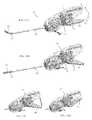
- FIGS. 11A-11Dillustrate a mesh tacker 70 , constructed and operative in accordance with an embodiment of the present invention, which is part of the kit and method for mesh deployment of the present invention.
- Mesh tacker 70may be similar in construction to the suture assembly described in copending U.S. patent application Ser. No. 12/427,778, the disclosure of which is incorporated herein by reference.
- Tacker 70may include a handle 72 with a first trigger assembly 74 and a second trigger assembly 76 . Both trigger assemblies 74 and 76 are coupled to an articulated applicator arm 78 which is disposed through a drive shaft 80 .
- the first trigger assembly 74is used to apply rotary tacks (not shown in these figures) from a distal end 82 of applicator arm 78 . This is accomplished by squeezing a trigger 84 towards the body of handle 72 (as shown by comparing FIGS. 11C and 11D ).
- the second trigger assembly 76is used to bend the distal end 82 of applicator arm 78 up ( FIG. 11A ) or down ( FIG. 11B ).
- the central (longitudinal) axis C of handle 72is tilted at an angle A in the range of about 7-25°, preferably about 77°, with respect to drive shaft 80 (that is, with respect to the proximal portion of applicator arm 78 which remains unbent), as seen in FIG. 11A .
- the tilted configuration of handle 72is an important ergonomic feature of tacker 70 .
- Prior art tackershave a pistol grip handle wherein the longitudinal axis of the handle is aligned or parallel with the drive shaft; there is no tilt.
- the prior art tackeris more cumbersome to use and can cause fatigue to the user. With the tilt of the present invention, tacker 70 is significantly more comfortable to use than prior art tackers.
- trigger 84is tilted at an angle B in the range of about 7-25°, preferably about 76°, with respect to drive shaft 80 .
- the angling tip and in-line handle of mesh tacker 70enable a secure tack fixation angle through fewer trocars, leading to improved outcomes and optimal patient care.
- the angulation of mesh tacker 70(the articulating tip) allows fixation of the mesh 360° from one side, and enables tacking from both the lateral and contralateral sides, and reaching difficult positions. This reduces or eliminates the need for placing additional trocars on the contralateral side.
- the in-line handleprovides a more ergonomic design that reduces stress and increases surgeon comfort throughout the entire fixation process.
- Mesh tacker 70can be loaded in an angled position for intraoperative efficiency.
- the tacksare absorbable (see below) and longer than other available tacks. The additional length of the tack and the angulating tip of the tacker help provide the laparoscopic surgeon more consistent and secure mesh fixation.
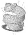
- FIG. 12illustrates a rotary tack 110 , constructed and operative in accordance with an embodiment of the present invention, which is part of the kit and method for mesh deployment of the present invention.
- Rotary tack 110may be similar in construction to the suture assembly described in copending U.S. patent application Ser. No. 12/427,780, the disclosure of which is incorporated herein by reference.
- Rotary tack 110is preferably constructed of a resorbable material.
- Tack 110may be constructed, without limitation, from a biodegradable polymer or copolymer of a type selected in accordance with the desired degradation time.
- a common biodegradable polymer used in absorbable sutures and the likeis poly(L-lactide) which has a degradation time of about twelve to eighteen months.
- the tackmay be constructed from an absorbable copolymer derived from glycolic and lactic acids, such as a synthetic polyester chemically similar to other commercial available glycolide and lactide copolymers. Glycolide and lactide, in vivo, degrade and absorb by hydrolysis into lactic acid and glycolic acid which are then metabolized by the body.
- tack 110includes a helical body 112 having a closed-loop base 114 and a helix of spiral coils 116 that extend from base 114 and which terminate in a tip 118 for piercing tissue (not shown).
- the baseis open, that is, the lowermost coil is not a continuous closed coil or loop.
- base 114is closed. This geometry provides tack 110 with superior strength, especially important for use with the resorbable material.
- Tip 118has a sharp edge at a wide angle W aimed upwards relative to the helix. Angle W is much greater than the helix angle of the coils.
- the inventionthus provides a kit for tissue repair, including mesh placer 10 , mesh stitcher 30 and mesh tacker 70 (and may also include rotary tacks 110 ).
- the kitmakes laparoscopic hernia repair (or other tissue repair) more consistent and efficient than the prior art.
- a preferred method of using the kitincludes first placing the mesh at the hernia repair site with the mesh placer, as described above.
- the surgeoncan operate the mesh placer with just one hand to place the mesh at the desired position and angular orientation. Afterwards, the surgeon may use his/her other hand to grasp the mesh placer and hold the mesh in place. This frees the dexterous hand of the surgeon for the next step (of course, if the surgeon is ambidextrous, there is no need to switch hands).
- the surgeonfastens the mesh to the tissue at the repair site. Fastening the mesh may be done by tacking the mesh to tissue with the mesh tacker using rotary tacks and/or by stitching the mesh to tissue with the mesh stitcher.
- the meshmay be fastened only with tacks, only with stitches, or any combination thereof.
- the stitching and tackingmay be done in any order. The stitching and tacking are done with the mesh stitcher and mesh tacker, respectively, as described above.
Landscapes
- Health & Medical Sciences (AREA)
- Life Sciences & Earth Sciences (AREA)
- Surgery (AREA)
- General Health & Medical Sciences (AREA)
- Public Health (AREA)
- Biomedical Technology (AREA)
- Heart & Thoracic Surgery (AREA)
- Veterinary Medicine (AREA)
- Engineering & Computer Science (AREA)
- Animal Behavior & Ethology (AREA)
- Molecular Biology (AREA)
- Nuclear Medicine, Radiotherapy & Molecular Imaging (AREA)
- Medical Informatics (AREA)
- Cardiology (AREA)
- Oral & Maxillofacial Surgery (AREA)
- Transplantation (AREA)
- Vascular Medicine (AREA)
- Rheumatology (AREA)
- Surgical Instruments (AREA)
- Prostheses (AREA)
- Materials For Medical Uses (AREA)
Abstract
Description
Claims (4)
Priority Applications (17)
| Application Number | Priority Date | Filing Date | Title |
|---|---|---|---|
| US12/484,258US8545523B2 (en) | 2009-06-15 | 2009-06-15 | Tissue repair method and kit |
| SI201031787TSI2442729T1 (en) | 2009-06-15 | 2010-06-17 | Tissue repair method and kit |
| EP10788943.8AEP2442729B1 (en) | 2009-06-15 | 2010-06-17 | Tissue repair method and kit |
| HRP20181820TTHRP20181820T1 (en) | 2009-06-15 | 2010-06-17 | Tissue repair method and kit |
| PCT/CN2010/074012WO2010145547A1 (en) | 2009-06-15 | 2010-06-17 | Tissue repair method and kit |
| KR1020127001137AKR101773540B1 (en) | 2009-06-15 | 2010-06-17 | Tissue repair method and kit |
| RU2012100635/14ARU2530384C2 (en) | 2009-06-15 | 2010-06-17 | Method of tissue plasty and set of instruments for tissue plasty |
| PL10788943TPL2442729T3 (en) | 2009-06-15 | 2010-06-17 | Tissue repair method and kit |
| CN201080034691.7ACN102548485B (en) | 2009-06-15 | 2010-06-17 | Tissue repair method and kit |
| LTEP10788943.8TLT2442729T (en) | 2009-06-15 | 2010-06-17 | Tissue repair method and kit |
| ES10788943.8TES2693457T3 (en) | 2009-06-15 | 2010-06-17 | Procedure and tissue repair kit |
| PT10788943TPT2442729T (en) | 2009-06-15 | 2010-06-17 | Tissue repair method and kit |
| NZ597549ANZ597549A (en) | 2009-06-15 | 2010-06-17 | Tissue repair method and kit - the kit contains a hand held suturing apparatus designed to place and secure a mesh on a body tissue |
| DK10788943.8TDK2442729T3 (en) | 2009-06-15 | 2010-06-17 | METHOD AND KIT FOR TISSUE REPAIR |
| TR2018/16218TTR201816218T4 (en) | 2009-06-15 | 2010-06-17 | Tissue repair method and kit. |
| AU2010262292AAU2010262292B2 (en) | 2009-06-15 | 2010-06-17 | Tissue repair method and kit |
| CA2766837ACA2766837C (en) | 2009-06-15 | 2010-06-17 | Tissue repair method and kit |
Applications Claiming Priority (1)
| Application Number | Priority Date | Filing Date | Title |
|---|---|---|---|
| US12/484,258US8545523B2 (en) | 2009-06-15 | 2009-06-15 | Tissue repair method and kit |
Publications (2)
| Publication Number | Publication Date |
|---|---|
| US20100318107A1 US20100318107A1 (en) | 2010-12-16 |
| US8545523B2true US8545523B2 (en) | 2013-10-01 |
Family
ID=43307072
Family Applications (1)
| Application Number | Title | Priority Date | Filing Date |
|---|---|---|---|
| US12/484,258Expired - Fee RelatedUS8545523B2 (en) | 2009-06-15 | 2009-06-15 | Tissue repair method and kit |
Country Status (17)
| Country | Link |
|---|---|
| US (1) | US8545523B2 (en) |
| EP (1) | EP2442729B1 (en) |
| KR (1) | KR101773540B1 (en) |
| CN (1) | CN102548485B (en) |
| AU (1) | AU2010262292B2 (en) |
| CA (1) | CA2766837C (en) |
| DK (1) | DK2442729T3 (en) |
| ES (1) | ES2693457T3 (en) |
| HR (1) | HRP20181820T1 (en) |
| LT (1) | LT2442729T (en) |
| NZ (1) | NZ597549A (en) |
| PL (1) | PL2442729T3 (en) |
| PT (1) | PT2442729T (en) |
| RU (1) | RU2530384C2 (en) |
| SI (1) | SI2442729T1 (en) |
| TR (1) | TR201816218T4 (en) |
| WO (1) | WO2010145547A1 (en) |
Families Citing this family (12)
| Publication number | Priority date | Publication date | Assignee | Title |
|---|---|---|---|---|
| US9486213B2 (en)* | 2011-11-14 | 2016-11-08 | Thd Lap Ltd. | Drive mechanism for articulating tacker |
| US8535339B2 (en) | 2011-12-18 | 2013-09-17 | Via Surgical Ltd. | Apparatus and method for suturing |
| US9888913B2 (en) | 2012-05-31 | 2018-02-13 | Via Surgical Ltd. | Variable depth surgical fixation |
| US9993245B2 (en) | 2013-03-11 | 2018-06-12 | Via Surgical Ltd. | Surgical tacker with quantity indicator |
| US9655709B2 (en) | 2013-09-26 | 2017-05-23 | Covidien Lp | Mesh deployment devices and kits |
| CA2980685A1 (en)* | 2015-04-01 | 2016-10-06 | Artack Medical (2013) Ltd. | Articulating medical device |
| ES2821006T3 (en) | 2015-04-23 | 2021-04-23 | Via Surgical Ltd | Surgical Fastener Locking and Delivery Mechanism |
| US20170055977A1 (en)* | 2015-08-24 | 2017-03-02 | Nir Altman | Multiple-needle suturing assembly |
| US10292702B2 (en)* | 2015-11-17 | 2019-05-21 | Ethicon, Inc. | Applicator instruments for dispensing surgical fasteners having articulating shafts and articulation control elements |
| CN108210111A (en)* | 2018-02-14 | 2018-06-29 | 南京畅丰生物科技有限公司 | Repair mesh sheet fixing device in basin bottom |
| US11793535B2 (en) | 2018-03-28 | 2023-10-24 | Zhangfan Mao | Endoluminal surgery device |
| CN110236613B (en)* | 2019-06-14 | 2020-11-27 | 毛张凡 | Endovascular surgical instruments |
Citations (15)
| Publication number | Priority date | Publication date | Assignee | Title |
|---|---|---|---|---|
| US5304187A (en)* | 1992-06-30 | 1994-04-19 | United States Surgical Corporation | Surgical element deployment apparatus |
| US5830221A (en)* | 1996-09-20 | 1998-11-03 | United States Surgical Corporation | Coil fastener applier |
| US5919184A (en)* | 1995-03-17 | 1999-07-06 | Tilton, Jr.; Eugene B. | Instrumentation for laparoscopic insertion and application of surgical sheet material |
| US6257241B1 (en)* | 1999-03-31 | 2001-07-10 | Ethicon Endo-Surgery, Inc. | Method for repairing tissue defects using ultrasonic radio frequency energy |
| US6416486B1 (en)* | 1999-03-31 | 2002-07-09 | Ethicon Endo-Surgery, Inc. | Ultrasonic surgical device having an embedding surface and a coagulating surface |
| US6425900B1 (en)* | 2000-10-19 | 2002-07-30 | Ethicon Endo-Surgery | Method for attaching hernia mesh |
| US20030004544A1 (en)* | 2001-04-04 | 2003-01-02 | Koichi Kawashima | Endoscopic instruments |
| US6638286B1 (en)* | 2000-11-16 | 2003-10-28 | Vascular Control Systems, Inc. | Doppler directed suture ligation device and method |
| US20050096673A1 (en)* | 2003-10-10 | 2005-05-05 | Stack Richard S. | Devices and methods for retaining a gastro-esophageal implant |
| US20050240260A1 (en)* | 2001-11-28 | 2005-10-27 | Aptus Endosystems, Inc. | Endovascular aneurysm repair system |
| US20060241622A1 (en)* | 2003-06-13 | 2006-10-26 | Zergiebel Earl M | Multiple member interconnect for surgical instrument and absorbable screw fastener |
| WO2008099382A1 (en) | 2007-02-14 | 2008-08-21 | Easylap Ltd. | Mesh deployment apparatus |
| EP1990014A2 (en) | 2007-05-10 | 2008-11-12 | Tyco Healthcare Group LP | Powered tacker instrument |
| WO2009069119A1 (en) | 2007-11-30 | 2009-06-04 | Easylap Ltd. | Suturing assembly and method |
| US7867222B1 (en)* | 1995-03-17 | 2011-01-11 | Tilton Jr Eugene B | Instrumentation for endoscopic surgical insertion and application of liquid, gel and like material |
Family Cites Families (7)
| Publication number | Priority date | Publication date | Assignee | Title |
|---|---|---|---|---|
| IL121752A0 (en)* | 1997-09-11 | 1998-02-22 | Gaber Benny | Stitching tool |
| US20010049538A1 (en)* | 1999-07-16 | 2001-12-06 | Ermanno E. Trabucco | Mesh plug kit for the inguinal box surgical technique for hernioplasty |
| US7004970B2 (en)* | 1999-10-20 | 2006-02-28 | Anulex Technologies, Inc. | Methods and devices for spinal disc annulus reconstruction and repair |
| US7380695B2 (en)* | 2003-05-20 | 2008-06-03 | Ethicon Endo-Surgery, Inc. | Surgical stapling instrument having a single lockout mechanism for prevention of firing |
| US7686826B2 (en)* | 2003-10-30 | 2010-03-30 | Cambridge Endoscopic Devices, Inc. | Surgical instrument |
| US7351197B2 (en)* | 2004-05-07 | 2008-04-01 | Ams Research Corporation | Method and apparatus for cystocele repair |
| FR2906131B1 (en)* | 2006-09-21 | 2009-04-24 | Cl Medical Sarl | SURGICAL TREATMENT FOR TREATMENT OF URINARY INCONTINENCE IN MAN |
- 2009
- 2009-06-15USUS12/484,258patent/US8545523B2/ennot_activeExpired - Fee Related
- 2010
- 2010-06-17AUAU2010262292Apatent/AU2010262292B2/ennot_activeCeased
- 2010-06-17LTLTEP10788943.8Tpatent/LT2442729T/enunknown
- 2010-06-17TRTR2018/16218Tpatent/TR201816218T4/enunknown
- 2010-06-17DKDK10788943.8Tpatent/DK2442729T3/enactive
- 2010-06-17CNCN201080034691.7Apatent/CN102548485B/ennot_activeExpired - Fee Related
- 2010-06-17WOPCT/CN2010/074012patent/WO2010145547A1/enactiveApplication Filing
- 2010-06-17CACA2766837Apatent/CA2766837C/ennot_activeExpired - Fee Related
- 2010-06-17PTPT10788943Tpatent/PT2442729T/enunknown
- 2010-06-17RURU2012100635/14Apatent/RU2530384C2/ennot_activeIP Right Cessation
- 2010-06-17HRHRP20181820TTpatent/HRP20181820T1/enunknown
- 2010-06-17SISI201031787Tpatent/SI2442729T1/enunknown
- 2010-06-17PLPL10788943Tpatent/PL2442729T3/enunknown
- 2010-06-17EPEP10788943.8Apatent/EP2442729B1/ennot_activeNot-in-force
- 2010-06-17NZNZ597549Apatent/NZ597549A/ennot_activeIP Right Cessation
- 2010-06-17ESES10788943.8Tpatent/ES2693457T3/enactiveActive
- 2010-06-17KRKR1020127001137Apatent/KR101773540B1/ennot_activeExpired - Fee Related
Patent Citations (16)
| Publication number | Priority date | Publication date | Assignee | Title |
|---|---|---|---|---|
| US5304187A (en)* | 1992-06-30 | 1994-04-19 | United States Surgical Corporation | Surgical element deployment apparatus |
| US7867222B1 (en)* | 1995-03-17 | 2011-01-11 | Tilton Jr Eugene B | Instrumentation for endoscopic surgical insertion and application of liquid, gel and like material |
| US5919184A (en)* | 1995-03-17 | 1999-07-06 | Tilton, Jr.; Eugene B. | Instrumentation for laparoscopic insertion and application of surgical sheet material |
| US5830221A (en)* | 1996-09-20 | 1998-11-03 | United States Surgical Corporation | Coil fastener applier |
| US6257241B1 (en)* | 1999-03-31 | 2001-07-10 | Ethicon Endo-Surgery, Inc. | Method for repairing tissue defects using ultrasonic radio frequency energy |
| US6416486B1 (en)* | 1999-03-31 | 2002-07-09 | Ethicon Endo-Surgery, Inc. | Ultrasonic surgical device having an embedding surface and a coagulating surface |
| US6425900B1 (en)* | 2000-10-19 | 2002-07-30 | Ethicon Endo-Surgery | Method for attaching hernia mesh |
| US6638286B1 (en)* | 2000-11-16 | 2003-10-28 | Vascular Control Systems, Inc. | Doppler directed suture ligation device and method |
| US20030004544A1 (en)* | 2001-04-04 | 2003-01-02 | Koichi Kawashima | Endoscopic instruments |
| US20050240260A1 (en)* | 2001-11-28 | 2005-10-27 | Aptus Endosystems, Inc. | Endovascular aneurysm repair system |
| US20060241622A1 (en)* | 2003-06-13 | 2006-10-26 | Zergiebel Earl M | Multiple member interconnect for surgical instrument and absorbable screw fastener |
| US20050096673A1 (en)* | 2003-10-10 | 2005-05-05 | Stack Richard S. | Devices and methods for retaining a gastro-esophageal implant |
| US7431725B2 (en)* | 2003-10-10 | 2008-10-07 | Synecor, Llc | Devices and methods for retaining a gastro-esophageal implant |
| WO2008099382A1 (en) | 2007-02-14 | 2008-08-21 | Easylap Ltd. | Mesh deployment apparatus |
| EP1990014A2 (en) | 2007-05-10 | 2008-11-12 | Tyco Healthcare Group LP | Powered tacker instrument |
| WO2009069119A1 (en) | 2007-11-30 | 2009-06-04 | Easylap Ltd. | Suturing assembly and method |
Non-Patent Citations (1)
| Title |
|---|
| PCT Search Report PCT/CN2010/074012. |
Also Published As
| Publication number | Publication date |
|---|---|
| CA2766837A1 (en) | 2010-12-23 |
| CN102548485A (en) | 2012-07-04 |
| CN102548485B (en) | 2015-03-25 |
| EP2442729A1 (en) | 2012-04-25 |
| AU2010262292B2 (en) | 2014-11-27 |
| US20100318107A1 (en) | 2010-12-16 |
| CA2766837C (en) | 2016-01-19 |
| ES2693457T3 (en) | 2018-12-11 |
| TR201816218T4 (en) | 2018-11-21 |
| LT2442729T (en) | 2018-11-12 |
| KR101773540B1 (en) | 2017-08-31 |
| RU2530384C2 (en) | 2014-10-10 |
| EP2442729A4 (en) | 2017-11-15 |
| NZ597549A (en) | 2012-07-27 |
| AU2010262292A1 (en) | 2012-02-02 |
| EP2442729B1 (en) | 2018-08-01 |
| HRP20181820T1 (en) | 2019-01-25 |
| WO2010145547A1 (en) | 2010-12-23 |
| DK2442729T3 (en) | 2018-11-26 |
| PL2442729T3 (en) | 2019-04-30 |
| KR20120032527A (en) | 2012-04-05 |
| RU2012100635A (en) | 2013-07-27 |
| PT2442729T (en) | 2018-11-20 |
| SI2442729T1 (en) | 2019-01-31 |
Similar Documents
| Publication | Publication Date | Title |
|---|---|---|
| US8545523B2 (en) | Tissue repair method and kit | |
| US10751045B2 (en) | Suture stitches for continuous surgical suturing | |
| JP5575809B2 (en) | Surgical stapler for applying large staples through a small delivery port and method of securing tissue folds using a surgical stapler | |
| JP5575808B2 (en) | Surgical stapler for applying large staples through a small delivery port and method of securing tissue folds using a surgical stapler | |
| JP5697606B2 (en) | Surgical stapler for applying large staples through a small delivery port and method of securing tissue folds using a surgical stapler | |
| US20120016389A1 (en) | Method of Performing Transgastric Ventral Hernia Repair and Tissue Anchors and Deployment Devices Therefor | |
| JP6087070B2 (en) | Surgical fastener for applying large staples through small delivery ports | |
| CN110300554A (en) | For auxiliary material to be attached to the mixed organization of surgical instruments | |
| JP6087071B2 (en) | Surgical fastener with safety mechanism | |
| WO2017051409A1 (en) | An applicator for treating a tissue | |
| JP6009239B2 (en) | Surgical stapler with adjustment mechanism | |
| CN114867419B (en) | Medical devices for bonding materials | |
| JP2019502516A (en) | Applicator instrument with off-axis surgical fastener delivery |
Legal Events
| Date | Code | Title | Description |
|---|---|---|---|
| AS | Assignment | Owner name:EASYLAP LTD., ISRAEL Free format text:ASSIGNMENT OF ASSIGNORS INTEREST;ASSIGNORS:MIZRAHY, MOSHE;RIMER, OFER;ALTMAN, NIR;AND OTHERS;REEL/FRAME:022822/0565 Effective date:20090614 | |
| STCF | Information on status: patent grant | Free format text:PATENTED CASE | |
| REMI | Maintenance fee reminder mailed | ||
| PRDP | Patent reinstated due to the acceptance of a late maintenance fee | Effective date:20171018 | |
| FEPP | Fee payment procedure | Free format text:SURCHARGE, PETITION TO ACCEPT PYMT AFTER EXP, UNINTENTIONAL. (ORIGINAL EVENT CODE: M2558); ENTITY STATUS OF PATENT OWNER: SMALL ENTITY Free format text:PETITION RELATED TO MAINTENANCE FEES FILED (ORIGINAL EVENT CODE: PMFP) Free format text:PETITION RELATED TO MAINTENANCE FEES GRANTED (ORIGINAL EVENT CODE: PMFG) | |
| MAFP | Maintenance fee payment | Free format text:PAYMENT OF MAINTENANCE FEE, 4TH YR, SMALL ENTITY (ORIGINAL EVENT CODE: M2551) Year of fee payment:4 | |
| FEPP | Fee payment procedure | Free format text:MAINTENANCE FEE REMINDER MAILED (ORIGINAL EVENT CODE: REM.); ENTITY STATUS OF PATENT OWNER: SMALL ENTITY | |
| LAPS | Lapse for failure to pay maintenance fees | Free format text:PATENT EXPIRED FOR FAILURE TO PAY MAINTENANCE FEES (ORIGINAL EVENT CODE: EXP.); ENTITY STATUS OF PATENT OWNER: SMALL ENTITY | |
| STCH | Information on status: patent discontinuation | Free format text:PATENT EXPIRED DUE TO NONPAYMENT OF MAINTENANCE FEES UNDER 37 CFR 1.362 | |
| FP | Lapsed due to failure to pay maintenance fee | Effective date:20211001 |