US8545493B2 - Flow rate monitor for fluid cooled microwave ablation probe - Google Patents
Flow rate monitor for fluid cooled microwave ablation probeDownload PDFInfo
- Publication number
- US8545493B2 US8545493B2US12/569,685US56968509AUS8545493B2US 8545493 B2US8545493 B2US 8545493B2US 56968509 AUS56968509 AUS 56968509AUS 8545493 B2US8545493 B2US 8545493B2
- Authority
- US
- United States
- Prior art keywords
- sensor
- generator
- microwave ablation
- microwave
- controller
- Prior art date
- Legal status (The legal status is an assumption and is not a legal conclusion. Google has not performed a legal analysis and makes no representation as to the accuracy of the status listed.)
- Active, expires
Links
- 238000002679ablationMethods0.000titleclaimsabstractdescription99
- 239000000523sampleSubstances0.000titleclaimsabstractdescription43
- 239000012530fluidSubstances0.000titleclaimsdescription37
- 230000002159abnormal effectEffects0.000claimsabstractdescription12
- 239000002826coolantSubstances0.000claimsdescription13
- 238000012544monitoring processMethods0.000claimsdescription5
- 239000013307optical fiberSubstances0.000claimsdescription4
- 238000006073displacement reactionMethods0.000claimsdescription3
- 238000000034methodMethods0.000description40
- 210000001519tissueAnatomy0.000description22
- 239000004020conductorSubstances0.000description13
- 230000006378damageEffects0.000description13
- 238000011282treatmentMethods0.000description7
- 230000000712assemblyEffects0.000description5
- 238000000429assemblyMethods0.000description5
- 238000001816coolingMethods0.000description5
- 238000010438heat treatmentMethods0.000description5
- 238000005259measurementMethods0.000description5
- 208000027418Wounds and injuryDiseases0.000description4
- 238000010276constructionMethods0.000description4
- 239000012809cooling fluidSubstances0.000description4
- 230000005672electromagnetic fieldEffects0.000description4
- 208000014674injuryDiseases0.000description4
- 230000005404monopoleEffects0.000description4
- 230000005855radiationEffects0.000description4
- 230000004044responseEffects0.000description4
- 206010028980NeoplasmDiseases0.000description3
- 201000011510cancerDiseases0.000description3
- 239000000919ceramicSubstances0.000description3
- 230000007547defectEffects0.000description3
- 238000001514detection methodMethods0.000description3
- 238000010586diagramMethods0.000description3
- 239000003989dielectric materialSubstances0.000description3
- 230000005670electromagnetic radiationEffects0.000description3
- 238000003780insertionMethods0.000description3
- 230000037431insertionEffects0.000description3
- 239000007788liquidSubstances0.000description3
- 229920002614Polyether block amidePolymers0.000description2
- 229910045601alloyInorganic materials0.000description2
- 239000000956alloySubstances0.000description2
- 230000005540biological transmissionEffects0.000description2
- 230000003139buffering effectEffects0.000description2
- 230000002950deficientEffects0.000description2
- 238000013461designMethods0.000description2
- 201000010099diseaseDiseases0.000description2
- 208000037265diseases, disorders, signs and symptomsDiseases0.000description2
- 230000000694effectsEffects0.000description2
- 230000000266injurious effectEffects0.000description2
- 239000000463materialSubstances0.000description2
- 229910052751metalInorganic materials0.000description2
- 239000002184metalSubstances0.000description2
- 150000002739metalsChemical class0.000description2
- 230000003287optical effectEffects0.000description2
- 230000008569processEffects0.000description2
- 210000002307prostateAnatomy0.000description2
- 206010020843HyperthermiaDiseases0.000description1
- 239000004697PolyetherimideSubstances0.000description1
- 229920004738ULTEM®Polymers0.000description1
- 238000009530blood pressure measurementMethods0.000description1
- 210000000481breastAnatomy0.000description1
- 230000010261cell growthEffects0.000description1
- 230000015271coagulationEffects0.000description1
- 238000005345coagulationMethods0.000description1
- 230000002596correlated effectEffects0.000description1
- 230000000875corresponding effectEffects0.000description1
- 230000007797corrosionEffects0.000description1
- 238000005260corrosionMethods0.000description1
- 230000003247decreasing effectEffects0.000description1
- 238000003745diagnosisMethods0.000description1
- 230000005611electricityEffects0.000description1
- 230000005674electromagnetic inductionEffects0.000description1
- 210000002216heartAnatomy0.000description1
- 230000036031hyperthermiaEffects0.000description1
- 238000009217hyperthermia therapyMethods0.000description1
- 230000002427irreversible effectEffects0.000description1
- 210000003734kidneyAnatomy0.000description1
- 230000000670limiting effectEffects0.000description1
- 210000004185liverAnatomy0.000description1
- 210000004072lungAnatomy0.000description1
- 230000007257malfunctionEffects0.000description1
- 230000003211malignant effectEffects0.000description1
- 238000004519manufacturing processMethods0.000description1
- 230000007246mechanismEffects0.000description1
- 208000007106menorrhagiaDiseases0.000description1
- 238000012986modificationMethods0.000description1
- 230000004048modificationEffects0.000description1
- 210000000056organAnatomy0.000description1
- 230000037368penetrate the skinEffects0.000description1
- 239000004033plasticSubstances0.000description1
- 229920003023plasticPolymers0.000description1
- 229920003223poly(pyromellitimide-1,4-diphenyl ether)Polymers0.000description1
- 229920001601polyetherimidePolymers0.000description1
- 229920001721polyimidePolymers0.000description1
- 229920000642polymerPolymers0.000description1
- 230000001902propagating effectEffects0.000description1
- 230000001012protectorEffects0.000description1
- 238000001959radiotherapyMethods0.000description1
- 230000009467reductionEffects0.000description1
- 230000002829reductive effectEffects0.000description1
- 238000002271resectionMethods0.000description1
- 230000000630rising effectEffects0.000description1
- 238000005070samplingMethods0.000description1
- 239000002002slurrySubstances0.000description1
- 230000001360synchronised effectEffects0.000description1
- 238000012360testing methodMethods0.000description1
- 238000002560therapeutic procedureMethods0.000description1
- 230000003685thermal hair damageEffects0.000description1
- 230000000007visual effectEffects0.000description1
- XLYOFNOQVPJJNP-UHFFFAOYSA-NwaterSubstancesOXLYOFNOQVPJJNP-UHFFFAOYSA-N0.000description1
Images


Classifications
- A—HUMAN NECESSITIES
- A61—MEDICAL OR VETERINARY SCIENCE; HYGIENE
- A61B—DIAGNOSIS; SURGERY; IDENTIFICATION
- A61B18/00—Surgical instruments, devices or methods for transferring non-mechanical forms of energy to or from the body
- A61B18/18—Surgical instruments, devices or methods for transferring non-mechanical forms of energy to or from the body by applying electromagnetic radiation, e.g. microwaves
- A61B18/1815—Surgical instruments, devices or methods for transferring non-mechanical forms of energy to or from the body by applying electromagnetic radiation, e.g. microwaves using microwaves
- A—HUMAN NECESSITIES
- A61—MEDICAL OR VETERINARY SCIENCE; HYGIENE
- A61B—DIAGNOSIS; SURGERY; IDENTIFICATION
- A61B18/00—Surgical instruments, devices or methods for transferring non-mechanical forms of energy to or from the body
- A61B2018/00005—Cooling or heating of the probe or tissue immediately surrounding the probe
- A61B2018/00011—Cooling or heating of the probe or tissue immediately surrounding the probe with fluids
- A61B2018/00023—Cooling or heating of the probe or tissue immediately surrounding the probe with fluids closed, i.e. without wound contact by the fluid
- A—HUMAN NECESSITIES
- A61—MEDICAL OR VETERINARY SCIENCE; HYGIENE
- A61B—DIAGNOSIS; SURGERY; IDENTIFICATION
- A61B18/00—Surgical instruments, devices or methods for transferring non-mechanical forms of energy to or from the body
- A61B18/18—Surgical instruments, devices or methods for transferring non-mechanical forms of energy to or from the body by applying electromagnetic radiation, e.g. microwaves
- A61B18/1815—Surgical instruments, devices or methods for transferring non-mechanical forms of energy to or from the body by applying electromagnetic radiation, e.g. microwaves using microwaves
- A61B2018/1861—Surgical instruments, devices or methods for transferring non-mechanical forms of energy to or from the body by applying electromagnetic radiation, e.g. microwaves using microwaves with an instrument inserted into a body lumen or cavity, e.g. a catheter
- A—HUMAN NECESSITIES
- A61—MEDICAL OR VETERINARY SCIENCE; HYGIENE
- A61B—DIAGNOSIS; SURGERY; IDENTIFICATION
- A61B18/00—Surgical instruments, devices or methods for transferring non-mechanical forms of energy to or from the body
- A61B18/18—Surgical instruments, devices or methods for transferring non-mechanical forms of energy to or from the body by applying electromagnetic radiation, e.g. microwaves
- A61B18/1815—Surgical instruments, devices or methods for transferring non-mechanical forms of energy to or from the body by applying electromagnetic radiation, e.g. microwaves using microwaves
- A61B2018/1869—Surgical instruments, devices or methods for transferring non-mechanical forms of energy to or from the body by applying electromagnetic radiation, e.g. microwaves using microwaves with an instrument interstitially inserted into the body, e.g. needles
Definitions
- the present disclosurerelates generally to microwave ablation procedures that utilize microwave surgical devices having a microwave antenna which may be inserted directly into tissue for diagnosis and treatment of diseases. More particularly, the present disclosure is directed to a system and method for verifying correct system operation of a microwave ablation system.
- One non-invasive proceduregenerally involves the treatment of tissue (e.g., a tumor) underlying the skin via the use of microwave energy.
- tissuee.g., a tumor
- the microwave energyis able to non-invasively penetrate the skin to reach the underlying tissue.
- this non-invasive proceduremay result in the unwanted heating of healthy tissue.
- the non-invasive use of microwave energyrequires a great deal of control.
- microwave probesthere are several types of microwave probes in use, e.g., monopole, dipole, and helical.
- One typeis a monopole antenna probe, which consists of a single, elongated microwave conductor exposed at the end of the probe. The probe is typically surrounded by a dielectric sleeve.
- the second type of microwave probe commonly usedis a dipole antenna, which consists of a coaxial construction having an inner conductor and an outer conductor with a dielectric junction separating a portion of the inner conductor.
- the inner conductormay be coupled to a portion corresponding to a first dipole radiating portion, and a portion of the outer conductor may be coupled to a second dipole radiating portion.
- the dipole radiating portionsmay be configured such that one radiating portion is located proximally of the dielectric junction, and the other portion is located distally of the dielectric junction.
- microwave energygenerally radiates perpendicularly from the axis of the conductor.
- the typical microwave antennahas a long, thin inner conductor that extends along the axis of the probe and is surrounded by a dielectric material and is further surrounded by an outer conductor around the dielectric material such that the outer conductor also extends along the axis of the probe.
- a portion or portions of the outer conductorcan be selectively removed.
- This type of constructionis typically referred to as a “leaky waveguide” or “leaky coaxial” antenna.
- Another variation on the microwave probeinvolves having the tip formed in a uniform spiral pattern, such as a helix, to provide the necessary configuration for effective radiation. This variation can be used to direct energy in a particular direction, e.g., perpendicular to the axis, in a forward direction (i.e., towards the distal end of the antenna), or combinations thereof.
- tissue ablationIn the case of tissue ablation, a high radio frequency electrical current in the range of about 500 MHz to about 10 GHz is applied to a targeted tissue site to create an ablation volume, which may have a particular size and shape. Ablation volume is correlated to antenna design, antenna performance, antenna impedance and tissue impedance. The particular type of tissue ablation procedure may dictate a particular ablation volume in order to achieve a desired surgical outcome. By way of example, and without limitation, a spinal ablation procedure may call for a longer, narrower ablation volume, whereas in a prostate ablation procedure, a more spherical ablation volume may be required.
- Microwave ablation devicesutilize sensors to determine if the system is working properly. However, without delivery of microwave energy, the sensors may indicate that the probe assembly status is normal. Further, defects in antenna assemblies may not be apparent except at high powers. As such, when microwave ablation system is tested using a low power routine, a post manufacture defect may not be apparent. This is especially important for high power microwave ablation devices, where failures may result in extremely high temperatures and flying debris.
- Fluid cooled or dielectrically buffered microwave ablation devicesmay also be used in ablation procedures to cool the microwave ablation probe. Cooling the ablation probe may enhance the overall ablation pattern of antenna, prevent damage to the antenna and prevent harm to the clinician or patient. However, during operation of the microwave ablation device, if the flow of coolant or buffering fluid is interrupted, the microwave ablation device may exhibit rapid failures due to the heat generated from the increased reflected power.
- the present disclosureprovides a microwave ablation system.
- the microwave ablation systemincludes a generator operable to output energy, an ablation probe coupled to the generator that is operable to deliver the energy to a tissue region, a controller operable to control the generator, and at least one or more sensors coupled to the ablation probe and the controller.
- the sensordetects an operating parameter of the ablation probe.
- the controllerperforms a system check by ramping up an energy output of the generator from a low energy level to a high energy level and monitors an output from the at least one sensor at predetermined intervals of time during the system check to determine an abnormal state.
- the controllercontrols the generator to cease the energy output when the controller determines an abnormal state.
- the senordetects a temperature of the ablation probe, radiating behavior of the ablation probe, fluid pressure, forward and reflective power and fluid flow of coolant.
- the senoris a thermocouple, thermistor, optical fiber, receiving antenna, rectenna, radio frequency power sensor, pressure sensor resistive junction or capacitive junction.
- the present disclosurealso provides a method of detecting an abnormal state in a microwave ablation system.
- the methodincludes the steps of outputting a low energy level from a generator to an ablation probe and detecting an operational parameter of the ablation probe at the low energy level.
- the detected operational parameteris compared to a predetermined range for the operational parameter and an energy level output of the generator is increased in response to the comparison.
- the microwave ablation systemceases output of energy from the generator in response to the detected operational parameter being outside the predetermined range.
- the operational parameteris a temperature of the ablation probe, radiating behavior of the ablation probe, fluid pressure, forward and reflective power, coolant flow in the probe and insertion depth of probe.
- FIG. 1shows a representative diagram of a variation of a microwave antenna assembly in accordance with an embodiment of the present disclosure
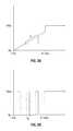
- FIGS. 2A-2Cshow graphs of time versus power in accordance with embodiments of the present disclosure
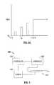
- FIG. 3shows a system block diagram according to an embodiment of the present disclosure
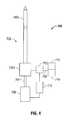
- FIG. 4shows a system block diagram according to another embodiment of the present disclosure.
- FIG. 5shows a flow chart describing a ramping procedure according to an embodiment of the present disclosure.
- proximalrefers to the end of the apparatus which is closer to the user and the term “distal” refers to the end of the apparatus which is further away from the user.
- distalrefers to the end of the apparatus which is further away from the user.
- clinicalrefers to any medical professional (i.e., doctor, surgeon, nurse, or the like) performing a medical procedure involving the use of embodiments described herein.
- Electromagnetic energyis generally classified by increasing energy or decreasing wavelength into radio waves, microwaves, infrared, visible light, ultraviolet, X-rays and gamma-rays.
- microwavegenerally refers to electromagnetic waves in the frequency range of 300 megahertz (MHz) (3 ⁇ 10 8 cycles/second) to 300 gigahertz (GHz) (3 ⁇ 10 11 cycles/second).
- RFgenerally refers to electromagnetic waves having a lower frequency than microwaves.
- ablation proceduregenerally refers to any ablation procedure, such as RF or microwave ablation or microwave ablation-assisted resection.
- transmission linegenerally refers to any transmission medium that can be used for the propagation of signals from one point to another.
- FIG. 1shows a microwave antenna assembly 100 in accordance with one embodiment of the present disclosure.
- Antenna assembly 100includes a radiating portion 12 that is connected by feedline 110 (or shaft) via cable 15 to connector 16 , which may further connect the assembly 100 to a power generating source 28 , e.g., a microwave or RF electrosurgical generator.
- Assembly 100is a dipole microwave antenna assembly, but other antenna assemblies, e.g., monopole or leaky wave antenna assemblies, may also utilize the principles set forth herein.
- Distal radiating portion 105 of radiating portion 12includes a tapered end 120 that terminates at a tip 123 to allow for insertion into tissue with minimal resistance. It is to be understood, however, that tapered end 120 may include other shapes, such as without limitation, a tip 123 that is rounded, flat, square, hexagonal, cylindroconical or any other polygonal shape.
- An insulating puck 130is disposed between distal radiating portion 105 and proximal radiating portion 140 .
- Puck 130may be formed from any suitable elastomeric or ceramic dielectric material by any suitable process.
- the puck 130is formed by overmolding from polyether block amide (e.g., Pebax® sold by Arkema), polyetherimide (e.g., Ultem® and/or Extern® sold by SABIC Innovative Plastics), polyimide-based polymer (e.g., Vespel® sold by DuPont), or ceramic.
- FIG. 2Ais a graph depicting an operation of the microwave ablation system according to an embodiment of the invention.
- the energy output from the generatoris 0 W.
- the energy outputalso increases at a constant slope ⁇ . Slope ⁇ is sufficient to prevent any harm to a clinician or patient and to prevent and damage to the system.
- the microwave ablation systemperforms a system check to determine if the system is in proper working order or if the system is malfunctioning. If the system is malfunctioning, an energy output from the generator is ceased thereby preventing any harm to a clinician or patient or preventing any further damage to the microwave ablation system.
- a series of pulsesmay be used during the start up procedure.
- the series of pulseshave a constant amplitude with a pulse width t W .
- a duty cycle for the pulsesmay be varied in order to adequately check the system without harming the patient or the clinician.
- the series of pulses during the start up proceduremay have a pulse width T W and vary in amplitude. The amplitude of the pulses may gradually reach an energy level sufficient to perform a microwave ablation procedure.
- microwave ablation systemsBy utilizing a system check that gradually subjects the device to increasing operational stresses (while monitoring sensor status) will allow for microwave ablation systems to limit the number of devices that are damaged due to operator error, such as not turning on the cooling fluid pump. It will also reduce the likelihood of patient and/or user injury from potentially defective assemblies or from user error.
- System 600has an antenna assembly 610 that imparts microwave energy to a patient.
- Antenna assembly 610is similar to antenna assembly 100 described above or antenna assembly may be a choked wet tip (CWT) antenna because the antenna performance needs cooling for power and tissue matching.
- Generator 620which is substantially similar to power generating source 28 , is coupled to antenna assembly 610 and provides a source of energy thereto.
- Controller 630is coupled to generator 620 and is configured to control generator 620 based on an input or signal from sensor 640 .
- Controller 630may be a microprocessor or any logic circuit able to receive an input or signal from sensor 640 and provide an output to control generator 620 .
- Sensor 640may be a thermocouple, thermistor, optical fiber, receiving antenna, rectenna, radio frequency power sensor, pressure sensor resistive junction or capacitive junction.
- Sensor 640may be a single sensor or an array of sensors to detect operational parameters of the antenna assembly 610 in order to determine if the microwave ablation system 600 is functioning properly. If the sensor 640 detects an abnormal value or level, the controller 630 controls the generator 620 to cease an energy output.
- Sensor 640may be incorporated into antenna assembly 610 or controller 630 or may be coupled to either antenna assembly 610 and/or controller 630 .
- Microwave ablation system 600may also be incorporated in antenna assembly 610 or may be arranged in two or more devices. For instance, controller 630 and generator 620 may be incorporated in a single device or may be separate devices.
- Temperature sensormay be a thermocouple, thermistor or an optical fiber.
- a thermocoupleis a junction between two different metals that produces a voltage related to a temperature difference. Thermocouples are can also be used to convert heat into electric power. Any circuit made of dissimilar metals will produce a temperature-related difference of voltage. Thermocouples for practical measurement of temperature are made of specific alloys, which in combination have a predictable and repeatable relationship between temperature and voltage. Different alloys are used for different temperature ranges and to resist corrosion. Where the measurement point is far from the measuring instrument, the intermediate connection can be made by extension wires, which are less costly than the materials used to make the sensor. Thermocouples are standardized against a reference temperature of 0 degrees Celsius. Electronic instruments can also compensate for the varying characteristics of the thermocouple to improve the precision and accuracy of measurements.
- a thermistoris a type of resistor whose resistance varies with temperature.
- Thermistorsare widely used as inrush current limiters, temperature sensors, self-resetting overcurrent protectors, and self-regulating heating elements.
- the material used in a thermistoris generally a ceramic or polymer. Thermistors typically achieve a high precision temperature response within a limited temperature range.
- Sensor 640may also be used to monitor radiating behavior, e.g., a receiving antenna or a rectenna.
- the receiving antennareceives radiation from the antenna assembly and provides an electrical signal to indicate the level of radiation.
- a rectennais a rectifying antenna, a special type of antenna that is used to directly convert microwave energy into DC electricity. Its elements are usually arranged in a multi-element phased array with a mesh pattern reflector element to make it directional.
- a simple rectennacan be constructed from a Schottky diode placed between antenna dipoles. The diode rectifies the current induced in the antenna by the microwaves.
- Sensor 640may also be an RF power sensor that monitors forward and reflected power.
- the RE power sensormeasures the power output of the generator 620 that is utilized by the antenna assembly 610 . It can also measure reflected power which is RF energy that is reflected from the ablated tissue region and received by the antenna assembly.
- Sensor 640may also be a pressure sensor for monitoring fluid and/or gas pressure.
- Pressure sensorgenerates a signal related to the pressure imposed. Typically, such a signal is electrical, but optical, visual, and auditory signals are also contemplated.
- Pressure sensorscan be classified in terms of pressure ranges they measure, temperature ranges of operation, and most importantly the type of pressure they measure. In terms of pressure type, pressure sensors can be divided into five categories. Absolute pressure sensors which measure the pressure relative to perfect vacuum pressure (0 PSI or no pressure). Gauge pressure sensors may be used in different applications because it can be calibrated to measure the pressure relative to a given atmospheric pressure at a given location. Vacuum pressure sensors are used to measure pressure less than the atmospheric pressure at a given location.
- Differential pressure sensorsmeasure the difference between two or more pressures introduced as inputs to the sensing unit. Differential pressure sensors may also be used to measure flow or level in pressurized vessels. Sealed pressure sensors are similar to the gauge pressure sensors except that it is previously calibrated by manufacturers to measure pressure relative to sea level pressure.
- Microwave ablation system 700may be similar to ablation systems described above with regard to FIGS. 1 and 3 .
- the system 700includes an ablation device 702 having an antenna 702 a and a handle 702 b used to ablate tissue.
- Generator 706supplies the ablation device with energy via coaxial cable 704 .
- Ablation device 702is supplied with coolant or buffering fluid from coolant supply 710 through conduit 708 .
- the coolantflows through the ablation device 702 as described above and exits the ablation device 702 via conduit 708 into chamber 714 .
- Conduit 708may be a multi lumen conduit having an inflow lumen for supplying the ablation device 702 with coolant and an outflow lumen for coolant to exit the ablation device 702 into the chamber 714 . Additionally, conduit 708 may be provided as two separate conduits, an inflow conduit and an outflow conduit.
- a sensor 712is provided to monitor the flow rate through conduit 708 .
- the ablation device 702may tend to exhibit rapid failures. By monitoring the fluid flow, damage to the ablation device 702 as well as harm to the clinician or patient can be prevented.
- Sensor 712provides an electrical signal to the controller 716 that represents a real-time fluid flow measurement or pressure measurement. Controller 716 compares the electrical signal to a predetermined range. If the electrical signal is within a predetermined range, the controller 716 signals the generator 706 to continue with the ablation procedure. If the electrical signal is outside the predetermined range, the controller 716 controls the generator 706 to cease the ablation procedure.
- Sensor 712may be placed anywhere along the fluid path.
- sensor 712may be placed in antenna 702 a , handle 702 b or along the inflow lumen/conduit or outflow lumen/conduit.
- the sampling rate of sensor 712should be sufficient enough to catch intermittent problems with the flow of fluid through the ablation system 700 .
- Sensor 712may be configured to detect the fluid flow during startup before microwave energy is delivered to the ablation device or during an ablation procedure.
- Sensor 712may be a pressure sensor similar to the pressure sensor described above with regard to FIG. 3 .
- the pressure sensormeasures the fluid pressure of the coolant or dielectric buffer and provides an electrical signal to the controller 716 .
- sensor 712may also be a fluid flow meter.
- fluid flow metersThere are many different types of fluid flow meters that can be used to measure the flow rate.
- a differential pressure flow meterthe flow is calculated by measuring the pressure drop over an obstructions inserted in the flow.
- the differential pressure flowmeteris based on the Bernoulli's Equation, where the pressure drop and the further measured signal is a function of the square of the flow speed.
- a velocity flowmeterthe flow is calculated by measuring the speed in one or more points in the flow, and integrating the flow speed over the flow area.
- a calorimetric flowmetertwo temperature sensors in close contact with the fluid but thermally insulated from each other are used.
- One of the two sensorsis constantly heated and the cooling effect of the flowing fluid is used to monitor the flowrate.
- a stationary (no flow) fluid conditionthere is a constant temperature difference between the two temperature sensors.
- heat energyis drawn from the heated sensor and the temperature difference between the sensors is reduced.
- the reductionis proportional to the flow rate of the fluid.
- Response timeswill vary due the thermal conductivity of the fluid. In general lower thermal conductivity require higher velocity for proper measurement.
- the calorimetric flowmetercan achieve relatively high accuracy at low flow rates.
- An electromagnetic flowmeteroperates on Faraday's law of electromagnetic induction that states that a voltage will be induced when a conductor moves through a magnetic field.
- the liquidserves as the conductor and the magnetic field is created by energized coils outside the flow tube.
- the voltage producedis directly proportional to the flow rate.
- Two electrodes mounted in the pipe walldetect the voltage that is measured by a secondary element.
- Electromagnetic flowmeterscan measure difficult and corrosive liquids and slurries, and they can measure flow in both directions with equal accuracy. Electromagnetic flowmeters have a relatively high power consumption and can only be used for electrical conductive fluids such as water.
- Ultrasonic flow metersmeasure the difference of the transit time of ultrasonic pulses propagating in and against flow direction. This time difference is a measure for the average velocity of the fluid along the path of the ultrasonic beam. By using the absolute transit times both the averaged fluid velocity and the speed of sound can be calculated. If a fluid is moving towards a transducer, the frequency of the returning signal will increase. As fluid moves away from a transducer, the frequency of the returning signal decrease. The frequency difference is equal to the reflected frequency minus the originating frequency and can be use to calculate the fluid flow speed.
- a positive displacement flowmetermeasures process fluid flow by precision-fitted rotors as flow measuring elements. Known and fixed volumes are displaced between the rotors. The rotation of the rotors are proportional to the volume of the fluid being displaced. The number of rotations of the rotor is counted by an integral electronic pulse transmitter and converted to volume and flow rate.
- the positive displacement rotor constructioncan be done in several ways: reciprocating piston meters (of single and multiple-piston types); and oval-gear meters having two rotating, oval-shaped gears with synchronized, close fitting teeth. With oval-gear meters, a fixed quantity of liquid passes through the meter for each revolution. Shaft rotation can be monitored to obtain specific flow rates.
- the procedurestarts at step 802 where the microwave ablation system is started.
- tis set to t0 where t is time and t0 is the initial startup time.
- a low energy levelis outputted from the generator 28 to the antenna assembly 100 .
- the sensordetects an operational parameter, such as temperature of the ablation probe, radiating behavior of the ablation probe, fluid pressure, forward and reflective power, fluid flow of coolant or insertion depth of probe, of the antenna assembly 100 as described above in step 808 .
- the detected operational parameteris compared to a predetermined range of values stored in the controller.
- the predetermined range of valuesmay be set by a clinician or they may be stored in the controller by a manufacturer of the microwave ablation system. If the detected operational parameter is within the predetermined range, the procedure proceeds to step 812 where a determination is made as to whether t is less than t RAMP . If t is less than t RAMP , then the procedure proceeds to step 814 where t is increased in predetermined intervals. t can be increased in intervals of N seconds or N minutes where N is any positive integer. In step 816 the energy level output of the generator is increased and step 808 , step 810 and step 812 are repeated. When t is no longer less than t RAMP , the procedures proceeds to step 820 where the ablation procedure is started and used on a patient. If the controller makes a determination in step 810 that the detected operational parameter in step 808 is not within the predetermined range, the procedure proceeds to step 818 where the controller controls the generator to cease energy output.
- the ramping procedure outlined abovemay avoid an assembly failure and potential clinician or patient injury.
- FIG. 5depicts a particular arrangement of steps to perform the system check during a ramping procedure, it should be understood that a different arrangement of steps may be used while still falling under the scope of the present disclosure.
- the power rampwould cease and return to zero.
- the rampmay be made long enough to reliably detect common malfunction mechanisms. Redundant circuit designs or redundant multiple sensor types may provide a form of sensor control.
- a pressure sensormay return abnormal pressure levels. As such, a power ramp would cease and the power does not reach a level where the coaxial cable would fail due to lack of cooling. If the antenna assembly is full of cooling fluid but the pump is not running, an abnormal reading from the pressure sensor or a rising temperature from a thermo probe would indicate that cooling of the probe is not sufficient most likely due to lack of flow. Therefore, the power ramp would cease and the power does not reach a level where the coaxial cable would fail due to lack of circulation.
- a electromagnetic field detectorsuch as the receiving antenna or rectenna would indicate abnormally high electromagnetic field levels along the shaft or around the handle of the antenna. The detection of the high electromagnetic field levels would prevent an unintended clinician or patient burn.
- the sensorsWhen the antenna assembly is subjected to high powers, defects may become readily apparent. On ramp up, the sensors indicate abnormal operating conditions thereby preventing the power level from reaching a level sufficient to cause device failure and avoiding clinician or patient injury.
- Utilizing a test routine of the ablation probe which gradually subjects the device to increasing operational stresses while monitoring sensor statuswill allow for MWA systems to limit the number of devices which are damaged due to operator error, such as not turning on the cooling fluid pump. It will also reduce the likely hood likelihood of patient and/or user injury from potentially defective assemblies or from user error. This is especially important for high power microwave ablation devices, where failures may result in extremely high temperatures and flying debris.
Landscapes
- Health & Medical Sciences (AREA)
- Surgery (AREA)
- Life Sciences & Earth Sciences (AREA)
- Biomedical Technology (AREA)
- Medical Informatics (AREA)
- Nuclear Medicine, Radiotherapy & Molecular Imaging (AREA)
- Electromagnetism (AREA)
- Engineering & Computer Science (AREA)
- Physics & Mathematics (AREA)
- Heart & Thoracic Surgery (AREA)
- Otolaryngology (AREA)
- Molecular Biology (AREA)
- Animal Behavior & Ethology (AREA)
- General Health & Medical Sciences (AREA)
- Public Health (AREA)
- Veterinary Medicine (AREA)
- Surgical Instruments (AREA)
Abstract
Description
Claims (10)
Priority Applications (1)
| Application Number | Priority Date | Filing Date | Title |
|---|---|---|---|
| US12/569,685US8545493B2 (en) | 2009-09-29 | 2009-09-29 | Flow rate monitor for fluid cooled microwave ablation probe |
Applications Claiming Priority (1)
| Application Number | Priority Date | Filing Date | Title |
|---|---|---|---|
| US12/569,685US8545493B2 (en) | 2009-09-29 | 2009-09-29 | Flow rate monitor for fluid cooled microwave ablation probe |
Publications (2)
| Publication Number | Publication Date |
|---|---|
| US20110077639A1 US20110077639A1 (en) | 2011-03-31 |
| US8545493B2true US8545493B2 (en) | 2013-10-01 |
Family
ID=43781158
Family Applications (1)
| Application Number | Title | Priority Date | Filing Date |
|---|---|---|---|
| US12/569,685Active2031-04-09US8545493B2 (en) | 2009-09-29 | 2009-09-29 | Flow rate monitor for fluid cooled microwave ablation probe |
Country Status (1)
| Country | Link |
|---|---|
| US (1) | US8545493B2 (en) |
Cited By (13)
| Publication number | Priority date | Publication date | Assignee | Title |
|---|---|---|---|---|
| US9028476B2 (en) | 2011-02-03 | 2015-05-12 | Covidien Lp | Dual antenna microwave resection and ablation device, system and method of use |
| US9192440B2 (en) | 2010-02-05 | 2015-11-24 | Covidien Lp | Electrosurgical devices with choke shorted to biological tissue |
| US9241762B2 (en) | 2010-06-03 | 2016-01-26 | Covidien Lp | Specific absorption rate measurement and energy-delivery device characterization using image analysis |
| US9375278B2 (en) | 2009-09-18 | 2016-06-28 | Covidien Lp | Tissue ablation system with energy distribution |
| US9480527B2 (en) | 2010-03-08 | 2016-11-01 | Covidien Lp | Microwave antenna probe having a deployable ground plane |
| US10028787B2 (en) | 2010-02-26 | 2018-07-24 | Covidien Lp | Tunable microwave ablation probe |
| US10213256B2 (en) | 2009-10-28 | 2019-02-26 | Covidien Lp | System and method for monitoring ablation size |
| US10251701B2 (en) | 2010-05-25 | 2019-04-09 | Covidien Lp | Flow rate verification monitor for fluid-cooled microwave ablation probe |
| US10327845B2 (en) | 2010-01-25 | 2019-06-25 | Covidien Lp | System and method for monitoring ablation size |
| US10390882B2 (en) | 2009-09-29 | 2019-08-27 | Covidien Lp | Flow rate monitor for fluid cooled microwave ablation probe |
| US20190374666A1 (en)* | 2018-06-07 | 2019-12-12 | Dickey Arndt | Systems and method for decontaminating a tube |
| US10588684B2 (en) | 2010-07-19 | 2020-03-17 | Covidien Lp | Hydraulic conductivity monitoring to initiate tissue division |
| US10987152B2 (en) | 2010-02-19 | 2021-04-27 | Covidien Lp | Ablation devices with dual operating frequencies, systems including same, and methods of adjusting ablation volume using same |
Families Citing this family (31)
| Publication number | Priority date | Publication date | Assignee | Title |
|---|---|---|---|---|
| US7553309B2 (en) | 2004-10-08 | 2009-06-30 | Covidien Ag | Electrosurgical system employing multiple electrodes and method thereof |
| US8292881B2 (en) | 2009-05-27 | 2012-10-23 | Vivant Medical, Inc. | Narrow gauge high strength choked wet tip microwave ablation antenna |
| US8323275B2 (en) | 2009-06-19 | 2012-12-04 | Vivant Medical, Inc. | Laparoscopic port with microwave rectifier |
| US9113925B2 (en)* | 2009-09-09 | 2015-08-25 | Covidien Lp | System and method for performing an ablation procedure |
| US8069553B2 (en) | 2009-09-09 | 2011-12-06 | Vivant Medical, Inc. | Method for constructing a dipole antenna |
| US8568401B2 (en) | 2009-10-27 | 2013-10-29 | Covidien Lp | System for monitoring ablation size |
| US8382750B2 (en)* | 2009-10-28 | 2013-02-26 | Vivant Medical, Inc. | System and method for monitoring ablation size |
| US8394092B2 (en)* | 2009-11-17 | 2013-03-12 | Vivant Medical, Inc. | Electromagnetic energy delivery devices including an energy applicator array and electrosurgical systems including same |
| US10039601B2 (en) | 2010-03-26 | 2018-08-07 | Covidien Lp | Ablation devices with adjustable radiating section lengths, electrosurgical systems including same, and methods of adjusting ablation fields using same |
| US8409188B2 (en) | 2010-03-26 | 2013-04-02 | Covidien Lp | Ablation devices with adjustable radiating section lengths, electrosurgical systems including same, and methods of adjusting ablation fields using same |
| US8652127B2 (en) | 2010-05-26 | 2014-02-18 | Covidien Lp | System and method for chemically cooling an ablation antenna |
| US8672933B2 (en) | 2010-06-30 | 2014-03-18 | Covidien Lp | Microwave antenna having a reactively-loaded loop configuration |
| US9039692B2 (en)* | 2011-09-20 | 2015-05-26 | Covidien Lp | Handheld medical devices including microwave amplifier unit at device handle |
| US8745846B2 (en) | 2011-09-20 | 2014-06-10 | Covidien Lp | Method of manufacturing handheld medical devices including microwave amplifier unit |
| US9039693B2 (en) | 2011-09-20 | 2015-05-26 | Covidien Lp | Handheld medical devices including microwave amplifier unit at device handle |
| US9023025B2 (en) | 2011-09-20 | 2015-05-05 | Covidien Lp | Handheld medical devices including microwave amplifier unit at device handle |
| US9033970B2 (en) | 2011-09-20 | 2015-05-19 | Covidien Lp | Handheld medical devices including microwave amplifier unit at device handle |
| US9113930B2 (en) | 2012-01-05 | 2015-08-25 | Covidien Lp | Ablation systems, probes, and methods for reducing radiation from an ablation probe into the environment |
| US9872719B2 (en) | 2013-07-24 | 2018-01-23 | Covidien Lp | Systems and methods for generating electrosurgical energy using a multistage power converter |
| US9655670B2 (en) | 2013-07-29 | 2017-05-23 | Covidien Lp | Systems and methods for measuring tissue impedance through an electrosurgical cable |
| CN105816240B (en)* | 2016-05-24 | 2018-09-28 | 赛诺微医疗科技(浙江)有限公司 | For the antenna module of microwave ablation and using its microwave melt needle |
| US11369434B2 (en) | 2016-06-22 | 2022-06-28 | Covidien Lp | Systems and methods for determining the status of a fluid-cooled microwave ablation system |
| US11197715B2 (en) | 2016-08-02 | 2021-12-14 | Covidien Lp | Ablation cable assemblies and a method of manufacturing the same |
| US11065053B2 (en) | 2016-08-02 | 2021-07-20 | Covidien Lp | Ablation cable assemblies and a method of manufacturing the same |
| US10376309B2 (en) | 2016-08-02 | 2019-08-13 | Covidien Lp | Ablation cable assemblies and a method of manufacturing the same |
| KR101804781B1 (en)* | 2016-09-27 | 2018-01-10 | 현대자동차주식회사 | imaging system |
| US20200155225A1 (en) | 2018-11-20 | 2020-05-21 | Biosense Webster (Israel) Ltd. | Irrigation control during ablation |
| US20200155223A1 (en) | 2018-11-20 | 2020-05-21 | Biosense Webster (Israel) Ltd. | Irrigation control during ablation |
| CN112865774B (en)* | 2020-12-31 | 2022-04-01 | 杭州堃博生物科技有限公司 | Protection method for abnormal operation of radio frequency, radio frequency host and radio frequency operating system |
| US12226143B2 (en) | 2020-06-22 | 2025-02-18 | Covidien Lp | Universal surgical footswitch toggling |
| CN115721411A (en)* | 2022-12-09 | 2023-03-03 | 南京亿高医疗科技股份有限公司 | Temperature control device, control method and microwave ablation needle |
Citations (83)
| Publication number | Priority date | Publication date | Assignee | Title |
|---|---|---|---|---|
| SU166452A1 (en) | В. А. Костров , Л. В. Смирнов | STOMATOLOGICAL DIATHERMOKOAGULATOR | ||
| DE390937C (en) | 1922-10-13 | 1924-03-03 | Adolf Erb | Device for internal heating of furnace furnaces for hardening, tempering, annealing, quenching and melting |
| DE1099658B (en) | 1959-04-29 | 1961-02-16 | Siemens Reiniger Werke Ag | Automatic switch-on device for high-frequency surgical devices |
| FR1275415A (en) | 1960-09-26 | 1961-11-10 | Device for detecting disturbances for electrical installations, in particular electrosurgery | |
| DE1139927B (en) | 1961-01-03 | 1962-11-22 | Friedrich Laber | High-frequency surgical device |
| DE1149832B (en) | 1961-02-25 | 1963-06-06 | Siemens Reiniger Werke Ag | High frequency surgical apparatus |
| FR1347865A (en) | 1962-11-22 | 1964-01-04 | Improvements to diathermo-coagulation devices | |
| DE1439302A1 (en) | 1963-10-26 | 1969-01-23 | Siemens Ag | High-frequency surgical device |
| SU401367A1 (en) | 1971-10-05 | 1973-10-12 | Тернопольский государственный медицинский институт | BIAKTIVNYE ELECTRO SURGICAL INSTRUMENT |
| FR2235669A1 (en) | 1973-07-07 | 1975-01-31 | Lunacek Boris | Gynaecological sterilisation instrument - has hollow electrode protruding from the end of a curved ended tube |
| DE2439587A1 (en) | 1973-08-23 | 1975-02-27 | Matburn Holdings Ltd | ELECTROSURGICAL DEVICE |
| DE2455174A1 (en) | 1973-11-21 | 1975-05-22 | Termiflex Corp | INPUT / OUTPUT DEVICE FOR DATA EXCHANGE WITH DATA PROCESSING DEVICES |
| DE2407559A1 (en) | 1974-02-16 | 1975-08-28 | Dornier System Gmbh | Tissue heat treatment probe - has water cooling system which ensures heat development only in treated tissues |
| DE2415263A1 (en) | 1974-03-29 | 1975-10-02 | Aesculap Werke Ag | Surgical H.F. coagulation probe has electrode tongs - with exposed ends of insulated conductors forming tong-jaws |
| DE2429021A1 (en) | 1974-06-18 | 1976-01-08 | Erbe Elektromedizin | Remote control for HF surgical instruments - uses cable with two conductors at most |
| FR2276027A1 (en) | 1974-06-25 | 1976-01-23 | Medical Plastics Inc | Plate electrode with connector - is clamped between connector jaws held by releasable locking device |
| DE2460481A1 (en) | 1974-12-20 | 1976-06-24 | Delma Elektro Med App | Electrode grip for remote HF surgical instrument switching - has shaped insulated piece with contact ring of sterilizable (silicon) rubber |
| DE2602517A1 (en) | 1975-01-23 | 1976-07-29 | Dentsply Int Inc | ELECTROSURGICAL DEVICE |
| DE2504280A1 (en) | 1975-02-01 | 1976-08-05 | Hans Heinrich Prof Dr Meinke | DEVICE FOR ELECTRIC TISSUE CUTTING IN SURGERY |
| FR2313708A1 (en) | 1975-06-02 | 1976-12-31 | Sybron Corp | Electro surgical instrument impulse control circuit - has potentiometer between patient electrodes and threshold switch for excessive voltage |
| DE2627679A1 (en) | 1975-06-26 | 1977-01-13 | Marcel Lamidey | HEMATISTIC HIGH FREQUENCY EXTRACTOR FORCEPS |
| DE2540968A1 (en) | 1975-09-13 | 1977-03-17 | Erbe Elektromedizin | Circuit for bipolar coagulation tweezers - permits preparation of tissues prior to coagulation |
| DE2820908A1 (en) | 1977-05-16 | 1978-11-23 | Joseph Skovajsa | DEVICE FOR THE LOCAL TREATMENT OF A PATIENT IN PARTICULAR FOR ACUPUNCTURE OR AURICULAR THERAPY |
| DE2803275A1 (en) | 1978-01-26 | 1979-08-02 | Aesculap Werke Ag | HF surgical appts. with active treatment and patient electrodes - has sensor switching generator to small voltage when hand-operated switch is closed |
| DE2823291A1 (en) | 1978-05-27 | 1979-11-29 | Rainer Ing Grad Koch | Coagulation instrument automatic HF switching circuit - has first lead to potentiometer and second to transistor base |
| SU727201A2 (en) | 1977-11-02 | 1980-04-15 | Киевский Научно-Исследовательский Институт Нейрохирургии | Electric surgical apparatus |
| DE2946728A1 (en) | 1979-11-20 | 1981-05-27 | Erbe Elektromedizin GmbH & Co KG, 7400 Tübingen | HF surgical appts. for use with endoscope - provides cutting or coagulation current at preset intervals and of selected duration |
| DE3143421A1 (en) | 1980-11-04 | 1982-05-27 | The Agency of Industrial Science and Technology, Tokyo | Laser scalpel |
| DE3045996A1 (en) | 1980-12-05 | 1982-07-08 | Medic Eschmann Handelsgesellschaft für medizinische Instrumente mbH, 2000 Hamburg | Electro-surgical scalpel instrument - has power supply remotely controlled by surgeon |
| FR2502935A1 (en) | 1981-03-31 | 1982-10-08 | Dolley Roger | Diathermic knife for coagulating tissues - has monitoring current added to HF coagulating current in order to control end of operation as function or resistance of coagulating tissues |
| DE3120102A1 (en) | 1981-05-20 | 1982-12-09 | F.L. Fischer GmbH & Co, 7800 Freiburg | ARRANGEMENT FOR HIGH-FREQUENCY COAGULATION OF EGG WHITE FOR SURGICAL PURPOSES |
| FR2517953A1 (en) | 1981-12-10 | 1983-06-17 | Alvar Electronic | Diaphanometer for optical examination of breast tissue structure - measures tissue transparency using two plates and optical fibre bundle cooperating with photoelectric cells |
| FR2573301A1 (en) | 1984-11-16 | 1986-05-23 | Lamidey Gilles | Surgical forceps and its control and monitoring apparatus |
| DE3510586A1 (en) | 1985-03-23 | 1986-10-02 | Erbe Elektromedizin GmbH, 7400 Tübingen | Control device for a high-frequency surgical instrument |
| DE3604823A1 (en) | 1986-02-15 | 1987-08-27 | Flachenecker Gerhard | HIGH FREQUENCY GENERATOR WITH AUTOMATIC PERFORMANCE CONTROL FOR HIGH FREQUENCY SURGERY |
| EP0246350A1 (en) | 1986-05-23 | 1987-11-25 | Erbe Elektromedizin GmbH. | Coagulation electrode |
| DE8712328U1 (en) | 1987-09-11 | 1988-02-18 | Jakoubek, Franz, 7201 Emmingen-Liptingen | Endoscopy forceps |
| DE3711511C1 (en) | 1987-04-04 | 1988-06-30 | Hartmann & Braun Ag | Method for determining gas concentrations in a gas mixture and sensor for measuring thermal conductivity |
| DE3904558A1 (en) | 1989-02-15 | 1990-08-23 | Flachenecker Gerhard | Radio-frequency generator with automatic power control for radio-frequency surgery |
| DE3942998A1 (en) | 1989-12-27 | 1991-07-04 | Delma Elektro Med App | Electro-surgical HF instrument for contact coagulation - has monitoring circuit evaluating HF voltage at electrodes and delivering switch=off signal |
| EP0521264A2 (en) | 1991-07-03 | 1993-01-07 | W.L. Gore & Associates GmbH | Antenna device with feed |
| JPH055106A (en) | 1990-07-31 | 1993-01-14 | Matsushita Electric Works Ltd | Production of alloy sintered body |
| JPH0540112A (en) | 1991-02-08 | 1993-02-19 | Tokico Ltd | Sample liquid component analyzer |
| DE4238263A1 (en) | 1991-11-15 | 1993-05-19 | Minnesota Mining & Mfg | Adhesive comprising hydrogel and crosslinked polyvinyl:lactam - is used in electrodes for biomedical application providing low impedance and good mechanical properties when water and/or moisture is absorbed from skin |
| EP0556705A1 (en) | 1992-02-20 | 1993-08-25 | DELMA ELEKTRO-UND MEDIZINISCHE APPARATEBAU GESELLSCHAFT mbH | High frequency surgery device |
| EP0558429A1 (en) | 1992-02-26 | 1993-09-01 | PECHINEY RECHERCHE (Groupement d'Intérêt Economique géré par l'ordonnance no. 67-821 du 23 Septembre 1967) | Method of simultaneous measuring of electrical resistivety and thermal conductivity |
| US5304214A (en)* | 1992-01-21 | 1994-04-19 | Med Institute, Inc. | Transurethral ablation catheter |
| DE4303882A1 (en) | 1993-02-10 | 1994-08-18 | Kernforschungsz Karlsruhe | Combined instrument for separating and coagulating in minimally invasive surgery |
| JPH06343644A (en) | 1993-05-04 | 1994-12-20 | Gyrus Medical Ltd | Surgical peritoneoscope equipment |
| DE4339049A1 (en) | 1993-11-16 | 1995-05-18 | Erbe Elektromedizin | Surgical system and instruments configuration device |
| JPH07265328A (en) | 1993-11-01 | 1995-10-17 | Gyrus Medical Ltd | Electrode assembly for electric surgery device and electric surgery device using it |
| JPH0856955A (en) | 1994-06-29 | 1996-03-05 | Gyrus Medical Ltd | Electric surgical apparatus |
| JPH08252263A (en) | 1994-12-21 | 1996-10-01 | Gyrus Medical Ltd | Electronic surgical incision instrument and electronic surgical incision device using the same |
| DE29616210U1 (en) | 1996-09-18 | 1996-11-14 | Olympus Winter & Ibe Gmbh, 22045 Hamburg | Handle for surgical instruments |
| US5575789A (en)* | 1994-10-27 | 1996-11-19 | Valleylab Inc. | Energizable surgical tool safety device and method |
| JPH0910223A (en) | 1995-06-23 | 1997-01-14 | Gyrus Medical Ltd | Generator and system for electric operation |
| DE19608716C1 (en) | 1996-03-06 | 1997-04-17 | Aesculap Ag | Bipolar surgical holding instrument |
| EP0836868A2 (en) | 1996-10-18 | 1998-04-22 | Gebr. Berchtold GmbH & Co. | High frequency surgical apparatus and method for operating same |
| DE19751106A1 (en) | 1996-11-27 | 1998-05-28 | Eastman Kodak Co | Laser printer with array of laser diodes |
| DE19717411A1 (en) | 1997-04-25 | 1998-11-05 | Aesculap Ag & Co Kg | Monitoring of thermal loading of patient tissue in contact region of neutral electrode of HF treatment unit |
| DE19751108A1 (en) | 1997-11-18 | 1999-05-20 | Beger Frank Michael Dipl Desig | Electrosurgical operation tool, especially for diathermy |
| DE19801173C1 (en) | 1998-01-15 | 1999-07-15 | Kendall Med Erzeugnisse Gmbh | Clamp connector for film electrodes |
| JPH11244298A (en) | 1997-12-19 | 1999-09-14 | Gyrus Medical Ltd | Electric surgical instrument |
| US6002968A (en)* | 1994-06-24 | 1999-12-14 | Vidacare, Inc. | Uterine treatment apparatus |
| DE19848540A1 (en) | 1998-10-21 | 2000-05-25 | Reinhard Kalfhaus | Circuit layout and method for operating a single- or multiphase current inverter connects an AC voltage output to a primary winding and current and a working resistance to a transformer's secondary winding and current. |
| JP2000342599A (en) | 1999-05-21 | 2000-12-12 | Gyrus Medical Ltd | Generator for electrosurgical operation, electrosurgical operation system, method for operating this system and method for performing amputation and resection of tissue by electrosurgical operation |
| JP2000350732A (en) | 1999-05-21 | 2000-12-19 | Gyrus Medical Ltd | Electrosurgical system, generator for electrosurgery, and method for cutting or excising tissue by electrosurgery |
| JP2001008944A (en) | 1999-05-28 | 2001-01-16 | Gyrus Medical Ltd | Electric surgical signal generator and electric surgical system |
| JP2001029356A (en) | 1999-06-11 | 2001-02-06 | Gyrus Medical Ltd | Electric and surgical signal generator |
| JP2001128990A (en) | 1999-05-28 | 2001-05-15 | Gyrus Medical Ltd | Electro surgical instrument and electrosurgical tool converter |
| EP1159926A2 (en) | 2000-06-03 | 2001-12-05 | Aesculap Ag | Scissor- or forceps-like surgical instrument |
| DE10224154A1 (en) | 2002-05-27 | 2003-12-18 | Celon Ag Medical Instruments | Application device for electrosurgical device for body tissue removal via of HF current has electrode subset selected from active electrode set in dependence on measured impedance of body tissue |
| DE10328514B3 (en) | 2003-06-20 | 2005-03-03 | Aesculap Ag & Co. Kg | Endoscopic surgical scissor instrument has internal pushrod terminating at distal end in transverse cylindrical head |
| FR2862813A1 (en) | 2003-11-20 | 2005-05-27 | Pellenc Sa | METHOD FOR BALANCED LOADING OF LITHIUM-ION OR POLYMER LITHIUM BATTERY |
| FR2864439A1 (en) | 2003-12-30 | 2005-07-01 | Image Guided Therapy | Tumor treating device for use by surgeon, has generator applying voltage to each of active electrodes in manner independent from other electrodes and having sinusoidal voltage generation unit adjusting amplitude and phase of voltage |
| DE102004022206A1 (en) | 2004-05-04 | 2005-12-01 | Bundesrepublik Deutschland, vertr. d. d. Bundesministerium für Wirtschaft und Arbeit, dieses vertr. d. d. Präsidenten der Physikalisch-Technischen Bundesanstalt | Sensor for measuring thermal conductivity comprises a strip composed of two parallel sections, and two outer heating strips |
| DE202005015147U1 (en) | 2005-09-26 | 2006-02-09 | Health & Life Co., Ltd., Chung-Ho | Biosensor test strip with identifying function for biological measuring instruments has functioning electrode and counter electrode, identification zones with coating of electrically conductive material and reaction zone |
| US20070050000A1 (en)* | 2005-07-21 | 2007-03-01 | Esch Brady D | Apparatus and method for ensuring thermal treatment of a hollow anatomical structure |
| US20070173805A1 (en)* | 2006-01-24 | 2007-07-26 | Craig Weinberg | Method and system for controlling an output of a radio-frequency medical generator having an impedance based control algorithm |
| US20080077126A1 (en)* | 2006-09-22 | 2008-03-27 | Rassoll Rashidi | Ablation for atrial fibrillation |
| US20080300588A1 (en) | 2005-12-02 | 2008-12-04 | Koninklijke Philips Electronics, N.V. | Automating the Ablation Procedure to Minimize the Need for Manual Intervention |
| US7481809B2 (en)* | 1996-01-05 | 2009-01-27 | Thermage, Inc. | Handpiece with RF electrode and non-volatile memory |
| US20090069799A1 (en) | 2000-12-28 | 2009-03-12 | Senorx, Inc. | Electrosurgical medical system and method |
Family Cites Families (66)
| Publication number | Priority date | Publication date | Assignee | Title |
|---|---|---|---|---|
| US419395A (en)* | 1890-01-14 | Elastic fabric | ||
| US436231A (en)* | 1890-09-09 | Reefing attachment for sails | ||
| US434903A (en)* | 1890-08-19 | Hoisting mechanism | ||
| US569171A (en)* | 1896-10-13 | Speed-indicating alarm | ||
| US487917A (en)* | 1892-12-13 | Torpedo-placer | ||
| US535851A (en)* | 1895-03-19 | Sleigh-knee | ||
| US562842A (en)* | 1896-06-30 | Fountain-pen | ||
| US416583A (en)* | 1889-12-03 | Automatic device for closing elevator-hatchway doors | ||
| US401268A (en)* | 1889-04-09 | Machine for picking cotton | ||
| US197601A (en)* | 1877-11-27 | Improvement in apparatus for distributing powder | ||
| US251857A (en)* | 1882-01-03 | Andeew flobe | ||
| US536616A (en)* | 1895-04-02 | Automatic circular knitting machine | ||
| US184556A (en)* | 1876-11-21 | Improvement in blind-adjusters | ||
| US389915A (en)* | 1888-09-25 | Life-boat | ||
| US607268A (en)* | 1898-07-12 | Cooking apparatus | ||
| US568524A (en)* | 1896-09-29 | Cultivator | ||
| US135425A (en)* | 1873-02-04 | Improvement in combined cradles and rocking-chairs | ||
| US562575A (en)* | 1896-06-23 | Superheater | ||
| US475082A (en)* | 1892-05-17 | gxnther | ||
| US250171A (en)* | 1881-11-29 | John h | ||
| US548644A (en)* | 1895-10-29 | Oiler | ||
| US136098A (en)* | 1873-02-18 | Improvement in embroidering attachments for sewing-machines | ||
| US199935A (en)* | 1878-02-05 | Improvement in lathe-chucks for turning stone | ||
| US619462A (en)* | 1899-02-14 | Pruning implement | ||
| US566299A (en)* | 1896-08-25 | Wrench | ||
| US423609A (en)* | 1890-03-18 | Bank-punch | ||
| US244850A (en)* | 1881-07-26 | burdick | ||
| US250110A (en)* | 1881-11-29 | tabor | ||
| US555576A (en)* | 1896-03-03 | Foot-rest for light driving-vehicles | ||
| US508700A (en)* | 1893-11-14 | Display-tray | ||
| US436237A (en)* | 1890-09-09 | Machine fob molding blocks oe bricks | ||
| US535856A (en)* | 1895-03-19 | The nor | ||
| US203474A (en)* | 1878-05-07 | Improvement in the manufacture of ornamental paper | ||
| US366298A (en)* | 1887-07-12 | Leather-finishing machine | ||
| US197473A (en)* | 1877-11-27 | Improvement in bolts and nuts | ||
| US568838A (en)* | 1896-10-06 | Night signaling | ||
| US568972A (en)* | 1896-10-06 | Clement engel | ||
| US236686A (en)* | 1881-01-18 | Wick-raiser for lamps | ||
| US504738A (en)* | 1893-09-12 | Frederick w | ||
| US568777A (en)* | 1896-10-06 | John k | ||
| US493302A (en)* | 1893-03-14 | Apparatus for the manufacture of glassware | ||
| US472831A (en)* | 1892-04-12 | Robert steel | ||
| US568067A (en)* | 1896-09-22 | Drill | ||
| US556010A (en)* | 1896-03-10 | Arthur william lotz and joseph huzelsteik | ||
| US476960A (en)* | 1892-06-14 | Carpet-stretcher | ||
| US129482A (en)* | 1872-07-16 | Improvement in combination locks | ||
| US620289A (en)* | 1899-02-28 | Means for forming type-line bars | ||
| US568551A (en)* | 1896-09-29 | Center-rest for lathes | ||
| US197405A (en)* | 1877-11-20 | Wateemah j | ||
| US542785A (en)* | 1895-07-16 | Franz thuringer | ||
| US561096A (en)* | 1896-06-02 | George w | ||
| US436239A (en)* | 1890-09-09 | Bicycle | ||
| US569685A (en)* | 1896-10-20 | Apparatus for shaping wood and pulp plates | ||
| US389906A (en)* | 1888-09-25 | Provision-safe | ||
| US606769A (en)* | 1898-07-05 | Electric heater or rheostat | ||
| US253457A (en)* | 1882-02-07 | Peter wiederer | ||
| US568883A (en)* | 1896-10-06 | smith | ||
| US194254A (en)* | 1877-08-14 | Improvement in pipe-tongs | ||
| US135690A (en)* | 1873-02-11 | Improvement in reversible magnets | ||
| US483742A (en)* | 1892-10-04 | Machine for making hollow cylinders of strips of sheet material and the process thereof | ||
| US181504A (en)* | 1876-08-22 | Improvement in casting car-wheels | ||
| US607221A (en)* | 1898-07-12 | Joining railway-bars | ||
| US542348A (en)* | 1895-07-09 | Safety-gate for elevators | ||
| US547155A (en)* | 1895-10-01 | Tank-wall for gas-receivers | ||
| US582857A (en)* | 1897-05-18 | Olin j | ||
| US147093A (en)* | 1874-02-03 | Improvement in pump-rod attachments |
- 2009
- 2009-09-29USUS12/569,685patent/US8545493B2/enactiveActive
Patent Citations (83)
| Publication number | Priority date | Publication date | Assignee | Title |
|---|---|---|---|---|
| SU166452A1 (en) | В. А. Костров , Л. В. Смирнов | STOMATOLOGICAL DIATHERMOKOAGULATOR | ||
| DE390937C (en) | 1922-10-13 | 1924-03-03 | Adolf Erb | Device for internal heating of furnace furnaces for hardening, tempering, annealing, quenching and melting |
| DE1099658B (en) | 1959-04-29 | 1961-02-16 | Siemens Reiniger Werke Ag | Automatic switch-on device for high-frequency surgical devices |
| FR1275415A (en) | 1960-09-26 | 1961-11-10 | Device for detecting disturbances for electrical installations, in particular electrosurgery | |
| DE1139927B (en) | 1961-01-03 | 1962-11-22 | Friedrich Laber | High-frequency surgical device |
| DE1149832B (en) | 1961-02-25 | 1963-06-06 | Siemens Reiniger Werke Ag | High frequency surgical apparatus |
| FR1347865A (en) | 1962-11-22 | 1964-01-04 | Improvements to diathermo-coagulation devices | |
| DE1439302A1 (en) | 1963-10-26 | 1969-01-23 | Siemens Ag | High-frequency surgical device |
| SU401367A1 (en) | 1971-10-05 | 1973-10-12 | Тернопольский государственный медицинский институт | BIAKTIVNYE ELECTRO SURGICAL INSTRUMENT |
| FR2235669A1 (en) | 1973-07-07 | 1975-01-31 | Lunacek Boris | Gynaecological sterilisation instrument - has hollow electrode protruding from the end of a curved ended tube |
| DE2439587A1 (en) | 1973-08-23 | 1975-02-27 | Matburn Holdings Ltd | ELECTROSURGICAL DEVICE |
| DE2455174A1 (en) | 1973-11-21 | 1975-05-22 | Termiflex Corp | INPUT / OUTPUT DEVICE FOR DATA EXCHANGE WITH DATA PROCESSING DEVICES |
| DE2407559A1 (en) | 1974-02-16 | 1975-08-28 | Dornier System Gmbh | Tissue heat treatment probe - has water cooling system which ensures heat development only in treated tissues |
| DE2415263A1 (en) | 1974-03-29 | 1975-10-02 | Aesculap Werke Ag | Surgical H.F. coagulation probe has electrode tongs - with exposed ends of insulated conductors forming tong-jaws |
| DE2429021A1 (en) | 1974-06-18 | 1976-01-08 | Erbe Elektromedizin | Remote control for HF surgical instruments - uses cable with two conductors at most |
| FR2276027A1 (en) | 1974-06-25 | 1976-01-23 | Medical Plastics Inc | Plate electrode with connector - is clamped between connector jaws held by releasable locking device |
| DE2460481A1 (en) | 1974-12-20 | 1976-06-24 | Delma Elektro Med App | Electrode grip for remote HF surgical instrument switching - has shaped insulated piece with contact ring of sterilizable (silicon) rubber |
| DE2602517A1 (en) | 1975-01-23 | 1976-07-29 | Dentsply Int Inc | ELECTROSURGICAL DEVICE |
| DE2504280A1 (en) | 1975-02-01 | 1976-08-05 | Hans Heinrich Prof Dr Meinke | DEVICE FOR ELECTRIC TISSUE CUTTING IN SURGERY |
| FR2313708A1 (en) | 1975-06-02 | 1976-12-31 | Sybron Corp | Electro surgical instrument impulse control circuit - has potentiometer between patient electrodes and threshold switch for excessive voltage |
| DE2627679A1 (en) | 1975-06-26 | 1977-01-13 | Marcel Lamidey | HEMATISTIC HIGH FREQUENCY EXTRACTOR FORCEPS |
| DE2540968A1 (en) | 1975-09-13 | 1977-03-17 | Erbe Elektromedizin | Circuit for bipolar coagulation tweezers - permits preparation of tissues prior to coagulation |
| DE2820908A1 (en) | 1977-05-16 | 1978-11-23 | Joseph Skovajsa | DEVICE FOR THE LOCAL TREATMENT OF A PATIENT IN PARTICULAR FOR ACUPUNCTURE OR AURICULAR THERAPY |
| SU727201A2 (en) | 1977-11-02 | 1980-04-15 | Киевский Научно-Исследовательский Институт Нейрохирургии | Electric surgical apparatus |
| DE2803275A1 (en) | 1978-01-26 | 1979-08-02 | Aesculap Werke Ag | HF surgical appts. with active treatment and patient electrodes - has sensor switching generator to small voltage when hand-operated switch is closed |
| DE2823291A1 (en) | 1978-05-27 | 1979-11-29 | Rainer Ing Grad Koch | Coagulation instrument automatic HF switching circuit - has first lead to potentiometer and second to transistor base |
| DE2946728A1 (en) | 1979-11-20 | 1981-05-27 | Erbe Elektromedizin GmbH & Co KG, 7400 Tübingen | HF surgical appts. for use with endoscope - provides cutting or coagulation current at preset intervals and of selected duration |
| DE3143421A1 (en) | 1980-11-04 | 1982-05-27 | The Agency of Industrial Science and Technology, Tokyo | Laser scalpel |
| DE3045996A1 (en) | 1980-12-05 | 1982-07-08 | Medic Eschmann Handelsgesellschaft für medizinische Instrumente mbH, 2000 Hamburg | Electro-surgical scalpel instrument - has power supply remotely controlled by surgeon |
| FR2502935A1 (en) | 1981-03-31 | 1982-10-08 | Dolley Roger | Diathermic knife for coagulating tissues - has monitoring current added to HF coagulating current in order to control end of operation as function or resistance of coagulating tissues |
| DE3120102A1 (en) | 1981-05-20 | 1982-12-09 | F.L. Fischer GmbH & Co, 7800 Freiburg | ARRANGEMENT FOR HIGH-FREQUENCY COAGULATION OF EGG WHITE FOR SURGICAL PURPOSES |
| FR2517953A1 (en) | 1981-12-10 | 1983-06-17 | Alvar Electronic | Diaphanometer for optical examination of breast tissue structure - measures tissue transparency using two plates and optical fibre bundle cooperating with photoelectric cells |
| FR2573301A1 (en) | 1984-11-16 | 1986-05-23 | Lamidey Gilles | Surgical forceps and its control and monitoring apparatus |
| DE3510586A1 (en) | 1985-03-23 | 1986-10-02 | Erbe Elektromedizin GmbH, 7400 Tübingen | Control device for a high-frequency surgical instrument |
| DE3604823A1 (en) | 1986-02-15 | 1987-08-27 | Flachenecker Gerhard | HIGH FREQUENCY GENERATOR WITH AUTOMATIC PERFORMANCE CONTROL FOR HIGH FREQUENCY SURGERY |
| EP0246350A1 (en) | 1986-05-23 | 1987-11-25 | Erbe Elektromedizin GmbH. | Coagulation electrode |
| DE3711511C1 (en) | 1987-04-04 | 1988-06-30 | Hartmann & Braun Ag | Method for determining gas concentrations in a gas mixture and sensor for measuring thermal conductivity |
| DE8712328U1 (en) | 1987-09-11 | 1988-02-18 | Jakoubek, Franz, 7201 Emmingen-Liptingen | Endoscopy forceps |
| DE3904558A1 (en) | 1989-02-15 | 1990-08-23 | Flachenecker Gerhard | Radio-frequency generator with automatic power control for radio-frequency surgery |
| DE3942998A1 (en) | 1989-12-27 | 1991-07-04 | Delma Elektro Med App | Electro-surgical HF instrument for contact coagulation - has monitoring circuit evaluating HF voltage at electrodes and delivering switch=off signal |
| JPH055106A (en) | 1990-07-31 | 1993-01-14 | Matsushita Electric Works Ltd | Production of alloy sintered body |
| JPH0540112A (en) | 1991-02-08 | 1993-02-19 | Tokico Ltd | Sample liquid component analyzer |
| EP0521264A2 (en) | 1991-07-03 | 1993-01-07 | W.L. Gore & Associates GmbH | Antenna device with feed |
| DE4238263A1 (en) | 1991-11-15 | 1993-05-19 | Minnesota Mining & Mfg | Adhesive comprising hydrogel and crosslinked polyvinyl:lactam - is used in electrodes for biomedical application providing low impedance and good mechanical properties when water and/or moisture is absorbed from skin |
| US5304214A (en)* | 1992-01-21 | 1994-04-19 | Med Institute, Inc. | Transurethral ablation catheter |
| EP0556705A1 (en) | 1992-02-20 | 1993-08-25 | DELMA ELEKTRO-UND MEDIZINISCHE APPARATEBAU GESELLSCHAFT mbH | High frequency surgery device |
| EP0558429A1 (en) | 1992-02-26 | 1993-09-01 | PECHINEY RECHERCHE (Groupement d'Intérêt Economique géré par l'ordonnance no. 67-821 du 23 Septembre 1967) | Method of simultaneous measuring of electrical resistivety and thermal conductivity |
| DE4303882A1 (en) | 1993-02-10 | 1994-08-18 | Kernforschungsz Karlsruhe | Combined instrument for separating and coagulating in minimally invasive surgery |
| JPH06343644A (en) | 1993-05-04 | 1994-12-20 | Gyrus Medical Ltd | Surgical peritoneoscope equipment |
| JPH07265328A (en) | 1993-11-01 | 1995-10-17 | Gyrus Medical Ltd | Electrode assembly for electric surgery device and electric surgery device using it |
| DE4339049A1 (en) | 1993-11-16 | 1995-05-18 | Erbe Elektromedizin | Surgical system and instruments configuration device |
| US6002968A (en)* | 1994-06-24 | 1999-12-14 | Vidacare, Inc. | Uterine treatment apparatus |
| JPH0856955A (en) | 1994-06-29 | 1996-03-05 | Gyrus Medical Ltd | Electric surgical apparatus |
| US5575789A (en)* | 1994-10-27 | 1996-11-19 | Valleylab Inc. | Energizable surgical tool safety device and method |
| JPH08252263A (en) | 1994-12-21 | 1996-10-01 | Gyrus Medical Ltd | Electronic surgical incision instrument and electronic surgical incision device using the same |
| JPH0910223A (en) | 1995-06-23 | 1997-01-14 | Gyrus Medical Ltd | Generator and system for electric operation |
| US7481809B2 (en)* | 1996-01-05 | 2009-01-27 | Thermage, Inc. | Handpiece with RF electrode and non-volatile memory |
| DE19608716C1 (en) | 1996-03-06 | 1997-04-17 | Aesculap Ag | Bipolar surgical holding instrument |
| DE29616210U1 (en) | 1996-09-18 | 1996-11-14 | Olympus Winter & Ibe Gmbh, 22045 Hamburg | Handle for surgical instruments |
| EP0836868A2 (en) | 1996-10-18 | 1998-04-22 | Gebr. Berchtold GmbH & Co. | High frequency surgical apparatus and method for operating same |
| DE19751106A1 (en) | 1996-11-27 | 1998-05-28 | Eastman Kodak Co | Laser printer with array of laser diodes |
| DE19717411A1 (en) | 1997-04-25 | 1998-11-05 | Aesculap Ag & Co Kg | Monitoring of thermal loading of patient tissue in contact region of neutral electrode of HF treatment unit |
| DE19751108A1 (en) | 1997-11-18 | 1999-05-20 | Beger Frank Michael Dipl Desig | Electrosurgical operation tool, especially for diathermy |
| JPH11244298A (en) | 1997-12-19 | 1999-09-14 | Gyrus Medical Ltd | Electric surgical instrument |
| DE19801173C1 (en) | 1998-01-15 | 1999-07-15 | Kendall Med Erzeugnisse Gmbh | Clamp connector for film electrodes |
| DE19848540A1 (en) | 1998-10-21 | 2000-05-25 | Reinhard Kalfhaus | Circuit layout and method for operating a single- or multiphase current inverter connects an AC voltage output to a primary winding and current and a working resistance to a transformer's secondary winding and current. |
| JP2000350732A (en) | 1999-05-21 | 2000-12-19 | Gyrus Medical Ltd | Electrosurgical system, generator for electrosurgery, and method for cutting or excising tissue by electrosurgery |
| JP2000342599A (en) | 1999-05-21 | 2000-12-12 | Gyrus Medical Ltd | Generator for electrosurgical operation, electrosurgical operation system, method for operating this system and method for performing amputation and resection of tissue by electrosurgical operation |
| JP2001008944A (en) | 1999-05-28 | 2001-01-16 | Gyrus Medical Ltd | Electric surgical signal generator and electric surgical system |
| JP2001128990A (en) | 1999-05-28 | 2001-05-15 | Gyrus Medical Ltd | Electro surgical instrument and electrosurgical tool converter |
| JP2001029356A (en) | 1999-06-11 | 2001-02-06 | Gyrus Medical Ltd | Electric and surgical signal generator |
| EP1159926A2 (en) | 2000-06-03 | 2001-12-05 | Aesculap Ag | Scissor- or forceps-like surgical instrument |
| US20090069799A1 (en) | 2000-12-28 | 2009-03-12 | Senorx, Inc. | Electrosurgical medical system and method |
| DE10224154A1 (en) | 2002-05-27 | 2003-12-18 | Celon Ag Medical Instruments | Application device for electrosurgical device for body tissue removal via of HF current has electrode subset selected from active electrode set in dependence on measured impedance of body tissue |
| DE10328514B3 (en) | 2003-06-20 | 2005-03-03 | Aesculap Ag & Co. Kg | Endoscopic surgical scissor instrument has internal pushrod terminating at distal end in transverse cylindrical head |
| FR2862813A1 (en) | 2003-11-20 | 2005-05-27 | Pellenc Sa | METHOD FOR BALANCED LOADING OF LITHIUM-ION OR POLYMER LITHIUM BATTERY |
| FR2864439A1 (en) | 2003-12-30 | 2005-07-01 | Image Guided Therapy | Tumor treating device for use by surgeon, has generator applying voltage to each of active electrodes in manner independent from other electrodes and having sinusoidal voltage generation unit adjusting amplitude and phase of voltage |
| DE102004022206A1 (en) | 2004-05-04 | 2005-12-01 | Bundesrepublik Deutschland, vertr. d. d. Bundesministerium für Wirtschaft und Arbeit, dieses vertr. d. d. Präsidenten der Physikalisch-Technischen Bundesanstalt | Sensor for measuring thermal conductivity comprises a strip composed of two parallel sections, and two outer heating strips |
| US20070050000A1 (en)* | 2005-07-21 | 2007-03-01 | Esch Brady D | Apparatus and method for ensuring thermal treatment of a hollow anatomical structure |
| DE202005015147U1 (en) | 2005-09-26 | 2006-02-09 | Health & Life Co., Ltd., Chung-Ho | Biosensor test strip with identifying function for biological measuring instruments has functioning electrode and counter electrode, identification zones with coating of electrically conductive material and reaction zone |
| US20080300588A1 (en) | 2005-12-02 | 2008-12-04 | Koninklijke Philips Electronics, N.V. | Automating the Ablation Procedure to Minimize the Need for Manual Intervention |
| US20070173805A1 (en)* | 2006-01-24 | 2007-07-26 | Craig Weinberg | Method and system for controlling an output of a radio-frequency medical generator having an impedance based control algorithm |
| US20080077126A1 (en)* | 2006-09-22 | 2008-03-27 | Rassoll Rashidi | Ablation for atrial fibrillation |
Non-Patent Citations (285)
| Title |
|---|
| Alexander et al., "Magnetic Resonance Image-Directed Stereotactic Neurosurgery: Use of Image Fusion with Computerized Tomography to Enhance Spatial Accuracy" Journal Neurosurgery, 83 (1995), pp. 271-276. |
| Anderson et al., "A Numerical Study of Rapid Heating for High Temperature Radio Frequency Hyperthermia" International Journal of Bio-Medical Computing, 35 (1994), pp. 297-307. |
| Anonymous. (1987) Homer Mammalok(TM) Breast Lesion Needle/Wire Localizer, Namic® Angiographic Systems Division, Glens Falls, New York, (Hospital products price list), 4 pages. |
| Anonymous. (1987) Homer Mammalok™ Breast Lesion Needle/Wire Localizer, Namic® Angiographic Systems Division, Glens Falls, New York, (Hospital products price list), 4 pages. |
| Anonymous. (1999) Auto Suture MIBB Site Marker: Single Use Clip Applier, United States Surgical (Product instructions), 2 pages. |
| Anonymous. (1999) MIBB Site Marker, United States Surgical (Sales brochure), 4 pages. |
| Anonymous. (2001) Disposable Chiba Biopsy Needles and Trays, Biopsy and Special Purpose Needles Cook Diagnostic and Interventional Products Catalog (products list), 4 pages. |
| Anonymous. Blunt Tubes with Finished Ends. Pointed Cannula, Popper & Sons Biomedical Instrument Division, (Products Price List), one page, Jul. 19, 2000. |
| Anonymous. Ground Cannulae, ISPG, New Milford, CT, (Advertisement) one page, Jul. 19, 2000. |
| B. F. Mullan et al., (May 1999) "Lung Nodules: Improved Wire for CT-Guided Localization," Radiology 211:561-565. |
| B. Levy M.D. et al., "Randomized Trial of Suture Versus Electrosurgical Bipolar Vessel Sealing in Vaginal Hysterectomy" Obstetrics & Gynecology, vol. 102, No. 1, Jul. 2003. |
| B. Levy M.D. et al., "Update on Hysterectomy New Technologies and Techniques" OBG Management, Feb. 2003. |
| B. Levy M.D., "Use of a New Vessel Ligation Device During Vaginal Hysterectomy" FIGO 2000, Washington, D.C. |
| B. T. Heniford M.D. et al., "Initial Research and Clinical Results with an Electrothermal Bipolar Vessel Sealer" Oct. 1999. |
| Bergdahl et al., "Studies on Coagulation and the Development of an Automatic Computerized Bipolar Coagulator" Joumal of Neurosurgery 75:1 (Jul. 1991). pp. 148-151. |
| Bulletin of the American Physical Society. vol. 47, No. 5, Aug. 2002, p. 41. |
| C. F. Gottlieb et al., "Interstitial Microwave Hyperthermia Applicators having Submillimetre Diameters", Int. J. Hyperthermia, vol. 6, No. 3, pp. 707-714. 1990. |
| C. H. Durney et al., "Antennas for Medical Applications", Antenna Handbook: Theory Application and Design, p. 24-40, Van Nostrand Reinhold, 1988 New York, V.T. Lo, S.W. Lee. |
| Carbonell et al., "Comparison of the Gyrus PlasmaKinetic Sealer and the Valleylab LigaSure(TM) Device in the Hemostasis of Small, Medium, and Large-Sized Arteries" Carolinas Laparoscopic and Advanced Surgery Program, Carolinas Medical Center, Charlotte, NC 2003. |
| Carbonell et al., "Comparison of the Gyrus PlasmaKinetic Sealer and the Valleylab LigaSure™ Device in the Hemostasis of Small, Medium, and Large-Sized Arteries" Carolinas Laparoscopic and Advanced Surgery Program, Carolinas Medical Center, Charlotte, NC 2003. |
| Carus et al., "Initial Experience With the LigaSure(TM) Vessel Sealing System in Abdominal Surgery" Innovations That Work, Jun. 2002. |
| Carus et al., "Initial Experience With the LigaSure™ Vessel Sealing System in Abdominal Surgery" Innovations That Work, Jun. 2002. |
| Chicharo et al., "A Sliding Goertzel Algorithm" Aug. 1996 DOS pp. 283-297 Signal Processing, Elsevier Science Publishers B.V. Amsterdam, NL, vol. 52, No. 3. |
| Chou, C.K., (1995) "Radiofrequency Hyperthermia in Cancer Therapy," Chapter 941n Biologic Effects of Nonionizing Electromagnetic Fields, CRC Press, Inc., pp. 1424-1428. |
| Chung et al., "Clinical Experience of Sutureless Closed Hemorrhoidectomy with LigaSure(TM)" Diseases of the Colon & Rectum, vol. 46, No. 1. Jan. 2003. |
| Chung et al., "Clinical Experience of Sutureless Closed Hemorrhoidectomy with LigaSure™" Diseases of the Colon & Rectum, vol. 46, No. 1. Jan. 2003. |
| Cosman et al., "Methods of Making Nervous System Lesions" In William RH, Rengachary SS (eds): Neurosurgery, New York: McGraw-Hill, vol. 111, (1984), pp. 2490-2499. |
| Cosman et al., "Radiofrequency Lesion Generation and its Effect on Tissue Impedence", Applied Neurophysiology, 51:230-242, 1988. |
| Cosman et al., "Theoretical Aspects of Radiofrequency Lesions in the Dorsal Root Entry Zone" Neurosurgery 15:(1984), pp. 945-950. |
| Crawford et al., "Use of the LigaSure(TM) Vessel Sealing System in Urologic Cancer Surger" Grand Rounds in Urology 1999, vol. 1, Issue 4, pp. 10-17. |
| Crawford et al., "Use of the LigaSure™ Vessel Sealing System in Urologic Cancer Surger" Grand Rounds in Urology 1999, vol. 1, Issue 4, pp. 10-17. |
| Dulemba et al., "Use of a Bipolar Electrothermal Vessel Sealer in Laparoscopically Assisted Vaginal Hysterectomy" Sales/Product Literature; Jan. 2004. |
| E. David Crawford, "Evaluation of a New Vessel Sealing Device in Urologic Cancer Surgery" Sales/Product Literature 2000. |
| E. David Crawford, "Use of a Novel Vessel Sealing Technology in Management of the Dorsal Veinous Complex" Sales/Product Literature 2000. |
| Esterline Product Literature, "Light Key: Visualize a Virtual Keyboard. One With No Moving Parts", Nov. 1, 2003; 4 pages. |
| Esterline, "Light Key Projection Keyboard" 2004 Advanced Input Systems, located at: <http://www.advanced-input.com/lightkey> last visited on Feb. 10, 2005. |
| Esterline, "Light Key Projection Keyboard" 2004 Advanced Input Systems, located at: last visited on Feb. 10, 2005. |
| European Search Report EP 03721482 dated Feb. 6, 2006. |
| European Search Report EP 04009964 dated Jul. 28, 2004. |
| European Search Report EP 04013772 dated Apr. 11, 2005. |
| European Search Report EP 04015980 dated Nov. 3, 2004. |
| European Search Report EP 04015981.6 dated Oct. 25, 2004. |
| European Search Report EP 04027314 dated Mar. 31, 2005. |
| European Search Report EP 04027479 dated Mar. 17, 2005. |
| European Search Report EP 04027705 dated Feb. 10, 2005. |
| European Search Report EP 04710258 dated Oct. 15, 2004. |
| European Search Report EP 04752343.6 dated Jul. 31, 2007. |
| European Search Report EP 04778192.7 dated Jul. 1, 2009. |
| European Search Report EP 05002027.0 dated May 12, 2005. |
| European Search Report EP 05002769.7 dated Jun. 19, 2006. |
| European Search Report EP 05013463.4 dated Oct. 7, 2005. |
| European Search Report EP 05013895 dated Oct. 21, 2005. |
| European Search Report EP 05014156.3 dated Jan. 4, 2006. |
| European Search Report EP 05016399 dated Jan. 13, 2006. |
| European Search Report EP 05017281 dated Nov. 24, 2005. |
| European Search Report EP 05019130.3 dated Oct. 27, 2005. |
| European Search Report EP 05019882 dated Feb. 16, 2006. |
| European Search Report EP 05020665.5 dated Feb. 27, 2006. |
| European Search Report EP 05020666.3 dated Feb. 27, 2006. |
| European Search Report EP 05021025.1 dated Mar. 13, 2006. |
| European Search Report EP 05021197.8 dated Feb. 20, 2006. |
| European Search Report EP 05021777 dated Feb. 23, 2006. |
| European Search Report EP 05021779.3 dated Feb. 2, 2006. |
| European Search Report EP 05021780.1 dated Feb. 23, 2006. |
| European Search Report EP 05021935 dated Jan. 27, 2006. |
| European Search Report EP 05021936.9 dated Feb. 6, 2006. |
| European Search Report EP 05021937.7 dated Jan. 23, 2006. |
| European Search Report EP 05021939 dated Jan. 27, 2006. |
| European Search Report EP 05021944.3 dated Jan. 25, 2006. |
| European Search Report EP 05022350.2 dated Jan. 30, 2006. |
| European Search Report EP 05023017.6 dated Feb. 24, 2006. |
| European Search Report EP 05025423.4 dated Jan. 19, 2007. |
| European Search Report EP 05025424 dated Jan. 30, 2007. |
| European Search Report EP 05810523 dated Jan. 29, 2009. |
| European Search Report EP 06000708.5 dated May 15, 2006. |
| European Search Report EP 06002279.5 dated Mar. 30, 2006. |
| European Search Report EP 06005185.1 dated May 10, 2006. |
| European Search Report EP 06005540 dated Sep. 24, 2007. |
| European Search Report EP 06006717.0 dated Aug. 11, 2006. |
| European Search Report EP 06006961 dated Oct. 22, 2007. |
| European Search Report EP 06006963 dated Jul. 25, 2006. |
| European Search Report EP 06008779.8 dated Jul. 13, 2006. |
| European Search Report EP 06009435 dated Jul. 13, 2006. |
| European Search Report EP 06010499.9 dated Jan. 29, 2008. |
| European Search Report EP 06014461.5 dated Oct. 31, 2006. |
| European Search Report EP 06018206.0 dated Oct. 20, 2006. |
| European Search Report EP 06019768 dated Jan. 17, 2007. |
| European Search Report EP 06020574.7 dated Oct. 2, 2007. |
| European Search Report EP 06020583.8 dated Feb. 7, 2007. |
| European Search Report EP 06020584.6 dated Feb. 1, 2007. |
| European Search Report EP 06020756.0 dated Feb. 16, 2007. |
| European Search Report EP 06022028.2 dated Feb. 13, 2007. |
| European Search Report EP 06023756.7 dated Feb. 21, 2008. |
| European Search Report EP 06024122.1 dated Apr. 16, 2007. |
| European Search Report EP 06024123.9 dated Mar. 6, 2007. |
| European Search Report EP 06025700.3 dated Apr. 12, 2007. |
| European Search Report EP 07000885.9 dated May 15, 2007. |
| European Search Report EP 07001480.8 dated Apr. 19, 2007. |
| European Search Report EP 07001481.6 dated May 2, 2007. |
| European Search Report EP 07001485.7 dated May 23, 2007. |
| European Search Report EP 07001488.1 dated Jun. 5, 2007. |
| European Search Report EP 07001489.9 dated Dec. 20, 2007. |
| European Search Report EP 07001491 dated Jun. 6, 2007. |
| European Search Report EP 07001527.6 dated May 18, 2007. |
| European Search Report EP 07007783.9 dated Aug. 14, 2007. |
| European Search Report EP 07008207.8 dated Sep. 13, 2007. |
| European Search Report EP 07009026.1 dated Oct. 8, 2007. |
| European Search Report EP 07009028 dated Jul. 16, 2007. |
| European Search Report EP 07009029.5 dated Jul. 20, 2007. |
| European Search Report EP 07009321.6 dated Aug. 28, 2007. |
| European Search Report EP 07009322.4 dated Jan. 14, 2008. |
| European Search Report EP 07010672.9 dated Oct. 16, 2007. |
| European Search Report EP 07010673.7 dated Oct. 5, 2007. |
| European Search Report EP 07013779.9 dated Oct. 26, 2007. |
| European Search Report EP 07015191.5 dated Jan. 23, 2007. |
| European Search Report EP 07015601.3 dated Jan. 4, 2007. |
| European Search Report EP 07015602.1 dated Dec. 20, 2007. |
| European Search Report EP 07018375.1 dated Jan. 8, 2008. |
| European Search Report EP 07018821 dated Jan. 14, 2008. |
| European Search Report EP 07019173.9 dated Feb. 12, 2008. |
| European Search Report EP 07019174.7 dated Jan. 29, 2008. |
| European Search Report EP 07019178.8 dated Feb. 12, 2008. |
| European Search Report EP 07020283.3 dated Feb. 5, 2008. |
| European Search Report EP 07253835.8 dated Dec. 20, 2007. |
| European Search Report EP 08001019 dated Sep. 23, 2008. |
| European Search Report EP 08004975 dated Jul. 24, 2008. |
| European Search Report EP 08006731.7 dated Jul. 29, 2008. |
| European Search Report EP 08006733 dated Jul. 7, 2008. |
| European Search Report EP 08006734.1 dated Aug. 18, 2008. |
| European Search Report EP 08006735.8 dated Jan. 8, 2009. |
| European Search Report EP 08011282 dated Aug. 14, 2009. |
| European Search Report EP 08011705 dated Aug. 20, 2009. |
| European Search Report EP 08012829.1 dated Oct. 29, 2008. |
| European Search Report EP 08015842 dated Dec. 5, 2008. |
| European Search Report EP 08019920.1 dated Mar. 27, 2009. |
| European Search Report EP 08169973.8 dated Apr. 6, 2009. |
| European Search Report EP 09156861.8 dated Aug. 4, 2009. |
| European Search Report EP 09161502.1 dated Sep. 2, 2009. |
| European Search Report EP 09166708 dated Oct. 15, 2009. |
| European Search Report EP 98300964.8 dated Dec. 13, 2000. |
| European Search Report EP 98944778 dated Nov. 7, 2000. |
| European Search Report EP 98958575.7 dated Oct. 29, 2002. |
| Geddes et al., "The Measurement of Physiologic Events by Electrical Impedence" Am. J. MI, Jan. Mar. 1964, pp. 16-27. |
| Goldberg et al., "Image-guided Radiofrequency Tumor Ablation: Challenges and Opportunities-Part I", (2001) J Vasc. Interv. Radiol, vol. 12, pp. 1021-1032. |
| Goldberg et al., "Tissue Ablation with Radiofrequency: Effect of Probe Size, Gauge, Duration, and Temperature on Lesion Volume" Acad Radio (1995) vol. 2, No. 5, pp. 399-404. |
| H. Schwarzmaier et al., "Magnetic Resonance Imaging of Microwave Induced Tissue Heating" Dept. of Laser Medicine & Dept. of Diagnostic Radiology; Heinrich-Heine-University, Duesseldorf, Germany; Dec. 8, 1994; pp. 729-731. |
| Heniford et al., "Initial Results with an Electrothermal Bipolar Vessel Sealer" Surgical Endoscopy (2001) 15:799-801. |
| Herman at al,, "Laparoscopic Intestinal Resection With the LigaSure™ Vessel Sealing System: A Case Report" Innovations That Work, Feb. 2002. |
| Humphries Jr. et al., "Finite•Element Codes to Model Electrical Heating and Non•Llnear Thermal Transport in Biological Media", Proc. ASME HTD-355, 131 (1997). |
| Ian D. McRury et al., The Effect of Ablation Sequence and Duration on Lesion Shape Using Rapidly Pulsed Radiofrequency Energy Through Electrodes, Feb. 2000, Springer Netherlands, vol. 4; No. 1, pp. 307-320. |
| International Search Report PCT/US01/11218 dated Aug. 14, 2001. |
| International Search Report PCT/US01/11224 dated Nov. 13, 2001. |
| International Search Report PCT/US01/11340 dated Aug. 16, 2001. |
| International Search Report PCT/US01/11420 dated Oct. 16, 2001. |
| International Search Report PCT/US02/01890 dated Jul. 25, 2002. |
| International Search Report PCT/US02/11100 dated Jul. 16, 2002. |
| International Search Report PCT/US03/09483 dated Aug. 13, 2003. |
| International Search Report PCT/US03/22900 dated Dec. 2, 2003. |
| International Search Report PCT/US03/37110 dated Jul. 25, 2005. |
| International Search Report PCT/US03/37111 dated Jul. 28, 2004. |
| International Search Report PCT/US03/37310 dated Aug. 13, 2004. |
| International Search Report PCT/US04/04685 dated Aug. 27, 2004. |
| International Search Report PCT/US04/13273 dated Dec. 15, 2004. |
| International Search Report PCT/US04/15311 dated Jan. 12, 2004. |
| International Search Report PCT/US05/36168 dated Aug. 28, 2006. |
| International Search Report PCT/US08/052460 dated Apr. 24, 2008. |
| International Search Report PCT/US09/31658 dated Mar. 11, 2009. |
| International Search Report PCT/US98/18640 dated Jan. 29, 1998. |
| International Search Report PCT/US98/23950 dated Jan. 14, 1998. |
| International Search Report PCT/US99/24869 dated Feb. 11, 2000. |
| Jarrett et al., "Use of the LigaSure™ Vessel Sealing System for Peri-Hilar Vessels in Laparoscopic Nephrectomy" Sales/Product Literature 2000. |
| Johnson et al., "Evaluation of a Bipolar Electrothermal Vessel Sealing Device in Hemorrhoidectomy" Sales/Product Literature, Jan. 2004. |
| Johnson, "Evaluation of the LigaSure™ Vessel Sealing System in Hemorrhoidectormy" American College of Surgeons (ACS) Clinic La Congress Poster (2000). |
| Johnson, "Use of the LigaSure™ Vessel Sealing System in Bloodless Hemorrhoidectomy" Innovations That Work, Mar. 2000. |
| Joseph G. Andriole M.D. et al., "Biopsy Needle Characteristics Assessed in the Laboratory", Radiology 148: 659-662, Sep. 1983. |
| Joseph Ortenberg, "LigaSure™ System Used in Laparoscopic 1st and 2nd Stage Orchiopexy" Innovations That Work, Nov. 2002. |
| Kennedy et al., "High-burst-strength, feedback-controlled bipolar vessel sealing" Surgical Endoscopy (1998) 12: 876-878. |
| Kopans, D.B. et al., (Nov. 1985) "Spring Hookwire Breast Lesion Localizer: Use with Rigid-Compression. Mammographic Systems," Radiology 157(2):537-538. |
| Koyle et al., "Laparoscopic Palomo Varicocele Ligation in Children and Adolescents" Pediatric Endosurgery & Innovative Techniques, vol. 6, No. 1, 2002. |
| LigaSure™ Vessel Sealing System, the Seal of Confidence in General , Gynecologic, Urologic, and Laparaoscopic Surgery, Sales/Product Literature, Jan. 2004. |
| Livraghi et al., (1995) "Saline-enhanced RF Tissue Ablation in the Treatment of Liver Metastases", Radiology, pp. 205-210, Abstract only. |
| Lyndon B. Johnson Space Center, Houston, Texas, "Compact Directional Microwave Antenna for Localized Heating," NASA Tech Briefs. Mar. 2008. |
| M. A. Astrahan, "A Localized Current Field Hyperthermia System for Use with 192-Iridium Interstitial Implants" Medical Physics. 9(3), May/Jun. 1982. |
| Magdy F. Iskander et al., "Design Optimization of Interstitial Antennas", IEEE Transactions on Biomedical Engineering, vol. 36, No. 2, Feb. 1989, pp. 238-246. |
| McGahan et al., (1995) "Percutaneous Ultrasound-guided Radiofrequency Electrocautery Ablation of Prostate Tissue in Dogs", Acad Radiol, vol. 2, No. 1: pp. 61-65. |
| McLellan et al., "Vessel Sealing for Hemostasis During Pelvic Surgery" Int'l Federation of Gynecology and Obstetrics FIGO World Congress 2000, Washington, DC. |
| MDTECH product literature (Dec. 1999) "FlexStrand": product description, 1 page. |
| MDTECH product literature (Mar. 2000) I'D Wire: product description, 1 page. |
| Medtrex Brochure "The O.R. Pro 300" 1 page, Sep. 1998. |
| Michael Choti. "Abdominoperineal Resection with the LigaSure™ Vessel Sealing System and LigaSure™ Atlas 20 cm Open Instrument" Innovations That Work. Jun. 2003. |
| Muller et al., "Extended Left Hemicolectomy Using the LigaSure™ Vessel Sealing System" Innovations That Work. LJ, Sep. 1999. |
| Murakami, R. et al., (1995). "Treatment of Hepatocellular Carcinoma: Value of Percutaneous Microwave Coagulation," American Journal of Radiology (AJR) 164:1159-1164. |
| Ni Wei et al., "A Signal Processing Method for the Coriolis Mass Flowmeter Based on a Normalized . . ." Journal of Applied Sciences.Yingyong Kexue Xuebao, Shanha CN, vol. 23, No. 2:(Mar. 2005); pp. 160-184, Abstract only. |
| Ogden, "Goertzel Alternative to the Fourier Transform" Jun. 1993 pp. 485-487 Electronics World; Reed Business Publishing, Sutton, Surrey, BG, vol. 99, No. 9, 1687. |
| Olsson M.D. et al., "Radical Cystectomy in Females" Current Surgical Techniques in Urology, vol. 14, Issue 3, 2001. |
| Organ, L W., "Electrophysiologic Principles of Radiofrequency Lesion Making" Appl. Neurophysiol, vol. 39: pp. 69-76 (1976/77). |
| P.R. Stauffer et al., "Interstitial Heating Technologies", Thermoradiotheray and Thermochemotherapy (1995) vol. I, Biology, Physiology, Physics, pp. 279-320. |
| Palazzo et al., "Randomized clinical trial of LigaSure™ versus open haemorrhoidectomy" British Journal of Surgery 2002,89,154-157 "Innovations in Electrosurgery" Sales/Product Literature; Dec. 31, 2000. |
| Paul G. Horgan, "A Novel Technique for Parenchymal Division During Hepatectomy" The American Journal of Surgery, vol. 181, No. 3, Apr. 2001, pp. 236-237. |
| Peterson et al., "Comparison of Healing Process Following Ligation with Sutures and Bipolar Vessel Sealing" Surgical Technology International (2001). |
| R. Gennari et al., (Jun. 2000) "Use of Technetium-99m-Labeled Colloid Albumin for Preoperative and Intraoperative Localization of Non palpable Breast Lesions," American College of Surgeons. 190(6):692-699. |
| Reidenbach, (1995) "First Experimental Results with Special Applicators for High-Frequency Interstitial Thermotherapy", Society Minimally Invasive Therapy, 4(Suppl 1):40 (Abstr). |
| Richard Wolf Medical Instruments Corp. Brochure, "Kleppinger Bipolar Forceps & Bipolar Generator" 3 pages, Jan. 1989. |
| Rothenberg et al., "Use of the LigaSure™ Vessel Sealing System in Minimally Invasive Surgery in Children" Int'l Pediatric Endosurgery Group (I PEG) 2000. |
| Sayfan et al., "Sutureless Closed Hemorrhoidectomy: A New Technique" Annals of Surgery, vol. 234. No. 1. Jul. 2001, pp. 21-24. |
| Sengupta et al., "Use of a Computer-Controlled Bipolar Diathermy System in Radical Prostatectomies and Other Open Urological Surgery" ANZ Journal of Surgery (2001) 71.9 pp. 538-540. |
| Sigel et al., "The Mechanism of Blood Vessel Closure by High Frequency Electrocoagulation" Surgery Gynecology & Obstetrics, Oct. 1965 pp. 823-831. |
| Solbiati et al., (2001) "Percutaneous Radio-frequency Ablation of Hepatic Metastases from Colorectal Cancer: Long-term Results in 117 Patients", Radiology, vol. 221, pp. 159-166. |
| Strasberg et al., "Use of a Bipolar Vassel-Sealing Device for Parenchymal Transection During Liver Surgery" Journal of Gastrointestinal Surgery, vol. 6, No. 4, Jul./Aug. 2002 pp. 569-574. |
| Sugita et al., "Bipolar Coagulator with Automatic Thermocontrol" J. Neurosurg., vol. 41, Dec. 1944, pp. 777-779. |
| Sylvain Labonte et al., "Monopole Antennas for Microwave Catheter Ablation", IEEE Trans. on Microwave Theory and Techniques, vol. 44, No. 10, pp. 1832-1840, Oct. 1995. |
| T. Matsukawa et al., "Percutaneous Microwave Coagulation Therapy in Liver Tumors", Acta Radiologica, vol. 38, pp. 410-415, 1997. |
| T. Seki et al., (1994) "Ultrasonically Guided Percutaneous Microwave Coagulation Therapy for Small Hepatocellular Carcinoma," Cancer 74(3):817-825. |
| U.S. Appl. No. 12/129,482, filed May 29, 2008. |
| U.S. Appl. No. 12/135,425, filed Jun. 9, 2008. |
| U.S. Appl. No. 12/135,690, filed Jun. 9, 2008. |
| U.S. Appl. No. 12/147,093, filed Jun. 26, 2008. |
| U.S. Appl. No. 12/181,504, filed Jul. 29, 2008. |
| U.S. Appl. No. 12/184,556, filed Aug. 1, 2008. |
| U.S. Appl. No. 12/194,254, filed Aug. 19, 2008. |
| U.S. Appl. No. 12/197,405, filed Aug. 25, 2008. |
| U.S. Appl. No. 12/197,473, filed Aug. 25, 2008. |
| U.S. Appl. No. 12/197,601, filed Aug. 25, 2008. |
| U.S. Appl. No. 12/199,935, filed Aug. 28, 2008. |
| U.S. Appl. No. 12/203,474, filed Sep. 3, 2008. |
| U.S. Appl. No. 12/236,686, filed Sep. 24, 2008. |
| U.S. Appl. No. 12/244,850, filed Oct. 3, 2008. |
| U.S. Appl. No. 12/250,110, filed Oct. 13, 2008. |
| U.S. Appl. No. 12/250,171, filed Oct. 13, 2008. |
| U.S. Appl. No. 12/251,857, filed Oct. 15, 2008. |
| U.S. Appl. No. 12/253,457, filed Oct. 17, 2008. |
| U.S. Appl. No. 12/366,298, filed Feb. 5, 2009. |
| U.S. Appl. No. 12/389,906, filed Feb. 20, 2009. |
| U.S. Appl. No. 12/389,915, filed Feb. 20, 2009. |
| U.S. Appl. No. 12/401,268, filed Mar. 10, 2009. |
| U.S. Appl. No. 12/416,583, filed Apr. 1, 2009. |
| U.S. Appl. No. 12/419,395, filed Apr. 7, 2009. |
| U.S. Appl. No. 12/423,609, filed Apr. 14, 2009. |
| U.S. Appl. No. 12/434,903, filed May 4, 2009. |
| U.S. Appl. No. 12/436,231, filed May 6, 2009. |
| U.S. Appl. No. 12/436,237, filed May 6, 2009. |
| U.S. Appl. No. 12/436,239, filed May 6, 2009. |
| U.S. Appl. No. 12/472,831, filed May 27, 2009. |
| U.S. Appl. No. 12/475,082, filed May 29, 2009. |
| U.S. Appl. No. 12/476,960, filed Jun. 2, 2009. |
| U.S. Appl. No. 12/487,917, filed Jun. 19, 2009. |
| U.S. Appl. No. 12/493,302, filed Jun. 29, 2009. |
| U.S. Appl. No. 12/504,738, filed Jul. 17, 2009. |
| U.S. Appl. No. 12/508,700, filed Jul. 24, 2009. |
| U.S. Appl. No. 12/535,851, filed Aug. 5, 2009. |
| U.S. Appl. No. 12/535,856, filed Aug. 5, 2009. |
| U.S. Appl. No. 12/536,616, filed Aug. 6, 2009. |
| U.S. Appl. No. 12/542,348, filed Aug. 17, 2009. |
| U.S. Appl. No. 12/542,785, filed Aug. 18, 2009. |
| U.S. Appl. No. 12/547,155, filed Aug. 25, 2009. |
| U.S. Appl. No. 12/548,644, filed Aug. 27, 2009. |
| U.S. Appl. No. 12/555,576, filed Sep. 8, 2009. |
| U.S. Appl. No. 12/556,010, filed Sep. 9, 2009. |
| U.S. Appl. No. 12/561,096, filed Sep. 16, 2009. |
| U.S. Appl. No. 12/562,575, filed Sep. 18, 2009. |
| U.S. Appl. No. 12/562,842, filed Sep. 18, 2009. |
| U.S. Appl. No. 12/566,299, filed Sep. 24, 2009. |
| U.S. Appl. No. 12/568,067, filed Sep. 28, 2009. |
| U.S. Appl. No. 12/568,524, filed Sep. 28, 2009. |
| U.S. Appl. No. 12/568,551, filed Sep. 28, 2009. |
| U.S. Appl. No. 12/568,777, filed Sep. 29, 2009. |
| U.S. Appl. No. 12/568,838, filed Sep. 29, 2009. |
| U.S. Appl. No. 12/568,883, filed Sep. 29, 2009. |
| U.S. Appl. No. 12/568,972, filed Sep. 29, 2009. |
| U.S. Appl. No. 12/569,171, filed Sep. 29, 2009. |
| U.S. Appl. No. 12/582,857, filed Oct. 21, 2009. |
| U.S. Appl. No. 12/606,769, filed Oct. 27, 2009. |
| U.S. Appl. No. 12/607,221, filed Oct. 28, 2009. |
| U.S. Appl. No. 12/607,268, filed Oct. 28, 2009. |
| U.S. Appl. No. 12/619,462, filed Nov. 16, 2009. |
| U.S. Appl. No. 12/620,289, filed Nov. 17, 2009. |
| Urologix, Inc.—Medical Professionals: Targis™ Technology (Date Unknown). "Overcoming the Challenge" located at: <http://www.urologix.com!medicaUtechnology.html > last visited on Apr. 27, 2001. 3 pages. |
| Urrutia et al., (1988). "Retractable-Barb Needle for Breast Lesion Localization: Use in 60 Cases," Radiology 169(3):845-847. |
| ValleyLab Brochure, "Electosurgery: A Historical Overview", Innovations in Electrosurgery, 1999. |
| Valleylab Brochure, "Reducing Needlestick Injuries in the Operating Room" 1 page, Mar. 2001. |
| Valleylab Brochure, "Valleylab Electroshield Monitoring System" 2 pages, Nov. 1995. |
| Vallfors et al., "Automatically Controlled Bipolar Electrocoagulation—‘COA-COMP’" Neurosurgical Review 7:2-3 (1984) pp. 187-190. |
| W. Scott Helton, "LigaSure™ Vessel Sealing System: Revolutionary Hemostasis Product for General Surgery" Sales/Product Literature 1999. |
| Wald et al., "Accidental Burns", JAMA, Aug. 16, 1971, vol. 217, No. 7, pp. 916-921. |
| Walt Boyles, "Instrumentation Reference Book", 2002, Butterworth-Heinemann, pp. 262-264. |
Cited By (20)
| Publication number | Priority date | Publication date | Assignee | Title |
|---|---|---|---|---|
| US9554855B2 (en) | 2009-09-18 | 2017-01-31 | Covidien Lp | Tissue ablation system with energy distribution |
| US11039885B2 (en) | 2009-09-18 | 2021-06-22 | Covidien Lp | Tissue ablation system with energy distribution |
| US9375278B2 (en) | 2009-09-18 | 2016-06-28 | Covidien Lp | Tissue ablation system with energy distribution |
| US10016237B2 (en) | 2009-09-18 | 2018-07-10 | Covidien Lp | Tissue ablation system with energy distribution |
| US10390882B2 (en) | 2009-09-29 | 2019-08-27 | Covidien Lp | Flow rate monitor for fluid cooled microwave ablation probe |
| US10213256B2 (en) | 2009-10-28 | 2019-02-26 | Covidien Lp | System and method for monitoring ablation size |
| US10327845B2 (en) | 2010-01-25 | 2019-06-25 | Covidien Lp | System and method for monitoring ablation size |
| US9192440B2 (en) | 2010-02-05 | 2015-11-24 | Covidien Lp | Electrosurgical devices with choke shorted to biological tissue |
| US10987152B2 (en) | 2010-02-19 | 2021-04-27 | Covidien Lp | Ablation devices with dual operating frequencies, systems including same, and methods of adjusting ablation volume using same |
| US10028787B2 (en) | 2010-02-26 | 2018-07-24 | Covidien Lp | Tunable microwave ablation probe |
| US9480527B2 (en) | 2010-03-08 | 2016-11-01 | Covidien Lp | Microwave antenna probe having a deployable ground plane |
| US10251701B2 (en) | 2010-05-25 | 2019-04-09 | Covidien Lp | Flow rate verification monitor for fluid-cooled microwave ablation probe |
| US9241762B2 (en) | 2010-06-03 | 2016-01-26 | Covidien Lp | Specific absorption rate measurement and energy-delivery device characterization using image analysis |
| US10588684B2 (en) | 2010-07-19 | 2020-03-17 | Covidien Lp | Hydraulic conductivity monitoring to initiate tissue division |
| US11517367B2 (en) | 2010-07-19 | 2022-12-06 | Covidien Lp | Hydraulic conductivity monitoring to initiate tissue division |
| US9028476B2 (en) | 2011-02-03 | 2015-05-12 | Covidien Lp | Dual antenna microwave resection and ablation device, system and method of use |
| US10238452B2 (en) | 2011-02-03 | 2019-03-26 | Covidien Lp | Dual antenna microwave resection and ablation device, system and method of use |
| US9301804B2 (en) | 2011-02-03 | 2016-04-05 | Covidien Lp | Dual antenna microwave resection and ablation device, system and method of use |
| US20190374666A1 (en)* | 2018-06-07 | 2019-12-12 | Dickey Arndt | Systems and method for decontaminating a tube |
| US10918751B2 (en) | 2018-06-07 | 2021-02-16 | Dickey Arndt | Systems and method for decontaminating a tube |
Also Published As
| Publication number | Publication date |
|---|---|
| US20110077639A1 (en) | 2011-03-31 |
Similar Documents
| Publication | Publication Date | Title |
|---|---|---|
| US8545493B2 (en) | Flow rate monitor for fluid cooled microwave ablation probe | |
| US9375273B2 (en) | System and method for checking high power microwave ablation system status on startup | |
| US9597151B2 (en) | Electrosurgical tissue ablation systems and methods capable of detecting excessive bending of a probe and alerting a user | |
| US10251701B2 (en) | Flow rate verification monitor for fluid-cooled microwave ablation probe | |
| US10182866B2 (en) | Flow rate monitor for fluid cooled microwave ablation probe | |
| US20190321098A1 (en) | Systems for thermal-feedback-controlled rate of fluid flow to fluid-cooled antenna assembly and methods of directing energy to tissue using same | |
| EP2497437B1 (en) | Systems for thermal-feedback-controlled rate of fluid flow to fluid-cooled antenna assembly | |
| EP2253286B1 (en) | Tissue impedance measurement using a secondary frequency | |
| US8974450B2 (en) | System and method for ablation procedure monitoring using electrodes | |
| AU2013242809B2 (en) | Re-hydration antenna for ablation | |
| AU2017200587A1 (en) | Re-hydration antenna for ablation |
Legal Events
| Date | Code | Title | Description |
|---|---|---|---|
| AS | Assignment | Owner name:VIVANT MEDICAL, INC., COLORADO Free format text:ASSIGNMENT OF ASSIGNORS INTEREST;ASSIGNORS:BRANNAN, JOSEPH D.;PETERSON, DARION;BONN, KENLYN S.;AND OTHERS;SIGNING DATES FROM 20090928 TO 20090929;REEL/FRAME:023300/0296 | |
| AS | Assignment | Owner name:VIVANT LLC, COLORADO Free format text:CHANGE OF NAME;ASSIGNOR:VIVANT MEDICAL, INC.;REEL/FRAME:030982/0599 Effective date:20121226 Owner name:COVIDIEN LP, MASSACHUSETTS Free format text:ASSIGNMENT OF ASSIGNORS INTEREST;ASSIGNOR:VIVANT LLC;REEL/FRAME:030982/0606 Effective date:20130402 | |
| STCF | Information on status: patent grant | Free format text:PATENTED CASE | |
| AS | Assignment | Owner name:CALDWELL, J. MICHAEL, SOUTH CAROLINA Free format text:SECURITY INTEREST;ASSIGNOR:EPIC TECH, LLC;REEL/FRAME:035573/0319 Effective date:20150101 | |
| AS | Assignment | Owner name:VIVANT MEDICAL LLC, COLORADO Free format text:CORRECTIVE ASSIGNMENT TO CORRECT THE ASSIGNEE NAME PREVIOUSLY RECORDED ON REEL 030982 FRAME 599. ASSIGNOR(S) HEREBY CONFIRMS THE CHANGE OF NAME OF VIVANT MEDICAL, INC. TO VIVANT MEDICAL LLC;ASSIGNOR:VIVANT MEDICAL, INC.;REEL/FRAME:037172/0176 Effective date:20121226 | |
| AS | Assignment | Owner name:COVIDIEN LP, MASSACHUSETTS Free format text:ASSIGNMENT OF ASSIGNORS INTEREST;ASSIGNOR:VIVANT MEDICAL LLC;REEL/FRAME:038250/0869 Effective date:20121228 | |
| FPAY | Fee payment | Year of fee payment:4 | |
| MAFP | Maintenance fee payment | Free format text:PAYMENT OF MAINTENANCE FEE, 8TH YEAR, LARGE ENTITY (ORIGINAL EVENT CODE: M1552); ENTITY STATUS OF PATENT OWNER: LARGE ENTITY Year of fee payment:8 | |
| MAFP | Maintenance fee payment | Free format text:PAYMENT OF MAINTENANCE FEE, 12TH YEAR, LARGE ENTITY (ORIGINAL EVENT CODE: M1553); ENTITY STATUS OF PATENT OWNER: LARGE ENTITY Year of fee payment:12 |