US8545488B2 - Cardiovascular imaging system - Google Patents
Cardiovascular imaging systemDownload PDFInfo
- Publication number
- US8545488B2 US8545488B2US12/649,759US64975909AUS8545488B2US 8545488 B2US8545488 B2US 8545488B2US 64975909 AUS64975909 AUS 64975909AUS 8545488 B2US8545488 B2US 8545488B2
- Authority
- US
- United States
- Prior art keywords
- catheter
- light guide
- balloon
- laser
- catheter body
- Prior art date
- Legal status (The legal status is an assumption and is not a legal conclusion. Google has not performed a legal analysis and makes no representation as to the accuracy of the status listed.)
- Active, expires
Links
Images


Classifications
- A—HUMAN NECESSITIES
- A61—MEDICAL OR VETERINARY SCIENCE; HYGIENE
- A61B—DIAGNOSIS; SURGERY; IDENTIFICATION
- A61B8/00—Diagnosis using ultrasonic, sonic or infrasonic waves
- A61B8/12—Diagnosis using ultrasonic, sonic or infrasonic waves in body cavities or body tracts, e.g. by using catheters
- A—HUMAN NECESSITIES
- A61—MEDICAL OR VETERINARY SCIENCE; HYGIENE
- A61B—DIAGNOSIS; SURGERY; IDENTIFICATION
- A61B18/00—Surgical instruments, devices or methods for transferring non-mechanical forms of energy to or from the body
- A61B18/18—Surgical instruments, devices or methods for transferring non-mechanical forms of energy to or from the body by applying electromagnetic radiation, e.g. microwaves
- A61B18/20—Surgical instruments, devices or methods for transferring non-mechanical forms of energy to or from the body by applying electromagnetic radiation, e.g. microwaves using laser
- A61B18/22—Surgical instruments, devices or methods for transferring non-mechanical forms of energy to or from the body by applying electromagnetic radiation, e.g. microwaves using laser the beam being directed along or through a flexible conduit, e.g. an optical fibre; Couplings or hand-pieces therefor
- A61B18/24—Surgical instruments, devices or methods for transferring non-mechanical forms of energy to or from the body by applying electromagnetic radiation, e.g. microwaves using laser the beam being directed along or through a flexible conduit, e.g. an optical fibre; Couplings or hand-pieces therefor with a catheter
- A61B18/245—Surgical instruments, devices or methods for transferring non-mechanical forms of energy to or from the body by applying electromagnetic radiation, e.g. microwaves using laser the beam being directed along or through a flexible conduit, e.g. an optical fibre; Couplings or hand-pieces therefor with a catheter for removing obstructions in blood vessels or calculi
- A—HUMAN NECESSITIES
- A61—MEDICAL OR VETERINARY SCIENCE; HYGIENE
- A61B—DIAGNOSIS; SURGERY; IDENTIFICATION
- A61B17/00—Surgical instruments, devices or methods
- A61B17/22—Implements for squeezing-off ulcers or the like on inner organs of the body; Implements for scraping-out cavities of body organs, e.g. bones; for invasive removal or destruction of calculus using mechanical vibrations; for removing obstructions in blood vessels, not otherwise provided for
- A61B2017/22038—Implements for squeezing-off ulcers or the like on inner organs of the body; Implements for scraping-out cavities of body organs, e.g. bones; for invasive removal or destruction of calculus using mechanical vibrations; for removing obstructions in blood vessels, not otherwise provided for with a guide wire
- A—HUMAN NECESSITIES
- A61—MEDICAL OR VETERINARY SCIENCE; HYGIENE
- A61B—DIAGNOSIS; SURGERY; IDENTIFICATION
- A61B17/00—Surgical instruments, devices or methods
- A61B17/22—Implements for squeezing-off ulcers or the like on inner organs of the body; Implements for scraping-out cavities of body organs, e.g. bones; for invasive removal or destruction of calculus using mechanical vibrations; for removing obstructions in blood vessels, not otherwise provided for
- A61B2017/22051—Implements for squeezing-off ulcers or the like on inner organs of the body; Implements for scraping-out cavities of body organs, e.g. bones; for invasive removal or destruction of calculus using mechanical vibrations; for removing obstructions in blood vessels, not otherwise provided for with an inflatable part, e.g. balloon, for positioning, blocking, or immobilisation
- A61B2017/22061—Implements for squeezing-off ulcers or the like on inner organs of the body; Implements for scraping-out cavities of body organs, e.g. bones; for invasive removal or destruction of calculus using mechanical vibrations; for removing obstructions in blood vessels, not otherwise provided for with an inflatable part, e.g. balloon, for positioning, blocking, or immobilisation for spreading elements apart
- A—HUMAN NECESSITIES
- A61—MEDICAL OR VETERINARY SCIENCE; HYGIENE
- A61B—DIAGNOSIS; SURGERY; IDENTIFICATION
- A61B18/00—Surgical instruments, devices or methods for transferring non-mechanical forms of energy to or from the body
- A61B18/18—Surgical instruments, devices or methods for transferring non-mechanical forms of energy to or from the body by applying electromagnetic radiation, e.g. microwaves
- A61B18/20—Surgical instruments, devices or methods for transferring non-mechanical forms of energy to or from the body by applying electromagnetic radiation, e.g. microwaves using laser
- A61B18/22—Surgical instruments, devices or methods for transferring non-mechanical forms of energy to or from the body by applying electromagnetic radiation, e.g. microwaves using laser the beam being directed along or through a flexible conduit, e.g. an optical fibre; Couplings or hand-pieces therefor
- A61B2018/2238—Surgical instruments, devices or methods for transferring non-mechanical forms of energy to or from the body by applying electromagnetic radiation, e.g. microwaves using laser the beam being directed along or through a flexible conduit, e.g. an optical fibre; Couplings or hand-pieces therefor with means for selectively laterally deflecting the tip of the fibre
- A—HUMAN NECESSITIES
- A61—MEDICAL OR VETERINARY SCIENCE; HYGIENE
- A61B—DIAGNOSIS; SURGERY; IDENTIFICATION
- A61B90/00—Instruments, implements or accessories specially adapted for surgery or diagnosis and not covered by any of the groups A61B1/00 - A61B50/00, e.g. for luxation treatment or for protecting wound edges
- A61B90/36—Image-producing devices or illumination devices not otherwise provided for
- A61B90/37—Surgical systems with images on a monitor during operation
- A61B2090/378—Surgical systems with images on a monitor during operation using ultrasound
- A61B2090/3782—Surgical systems with images on a monitor during operation using ultrasound transmitter or receiver in catheter or minimal invasive instrument
Definitions
- Arteriesare the primary blood vessels that are responsible for providing blood and oxygen to the heart muscle. Arterial disease occurs when arteries become narrowed or blocked by a buildup of plaque (as some examples, atherosclerotic plaque or other deposits). When the blockage is severe, the flow of blood and oxygen to the heart muscle is reduced, causing chest pain. Arterial blockage by clots formed in a human body may be relieved in a number of traditional ways. Drug therapy, including nitrates, beta-blockers, and peripheral vasodilatator drugs to dilate the arteries or thrombolytic drugs to dissolve the clot, can be effective. If drug treatment fails, angioplasty may be used to reform or remove the atherosclerotic plaque or other deposits in the artery.
- Excimer laser angioplasty procedureis similar in some respects to conventional coronary balloon angioplasty.
- a narrow, flexible tube, the laser catheteris inserted into an artery in the arm or leg.
- the laser cathetercontains one or more optical fibers, which can transmit laser energy.
- the laser catheteris then advanced inside the artery to the targeted obstruction at the desired treatment site. After the laser catheter has been positioned, the laser is energized to “remove” the obstruction.
- the lesionis often engaged similar to conventional balloon angioplasty by crossing the blockage with a guidewire.
- the laser catheter's thin, flexible optical fibersfacilitate the desired positioning and alignment of the catheter.
- the clinicianuses the excimer laser, the clinician performs a controlled blockage removal by sending bursts of ultraviolet light through the catheter and against the blockage, a process called “ablation.”
- the catheteris then slowly advanced through the blockage reopening the artery. If there are multiple blockages, the catheter is advanced to the next blockage site and the above step is repeated. When the indicated blockages appear to be cleared, the catheter is withdrawn.
- the clinicianis able to ablate only material that is typically directly in front of the distal end of the catheter.
- the debulked tissue areais limited to an area approximately the size of the optical fiber area at the distal end of the catheter.
- follow-up balloon angioplastyis recommended.
- Imaging during atherectomy or angioplasty proceduresoften uses fluoroscopy imaging techniques for targeting and ablation of blockages. Fluoroscopy, however, has limitations. For example, does not allow a doctor or technician to visualize plaque or vessel walls.
- a laser cathetercan include a catheter body, a light guide, a distal tip, and an imaging device disposed distal relative to the exit aperture of the light guide.
- the catheter bodyfor example may include a central axis, a proximal end and a distal end.
- the catheter bodymay also include a lumen disposed between the proximal end and the distal end, the lumen having an opening at the distal end.
- the light guidemay also include a proximal end and a distal end.
- the light guidemay also include at least one fiber optic and may at least partially be disposed within the lumen and/or movable therein.
- the distal tipmay be positioned at the periphery of the catheter body and may extend from the distal end of the catheter body.
- the imaging devicecan be disposed on the distal tip, for example, at a position distal from the exit aperture of the light guide.
- the distal tipmay also include a guidewire lumen that includes a guidewire port at the distal end of the distal tip.
- a retaining wiremay also be used in some embodiments and can be coupled with the distal tip and slidably coupled with the light guide.
- a balloonfor example, may be positioned between the opening at the first distal end of the catheter body and the distal tip.
- the balloon cathetercan include a catheter body, for example may include a central axis, a proximal end and a distal end.
- the catheter bodymay also include a lumen disposed between the proximal end and the distal end, the lumen having an opening at the distal end.
- the balloon cathetercan also include a light guide that may also include a proximal end and a distal end.
- the light guidemay also include at least one fiber optic and may at least partially be disposed within the lumen and/or movable therein.
- the ballooncan be disposed at the radial exterior of the catheter body. In use, for example, the balloon can be inflated such that the balloon makes contact with a vessel wall. Contact with the vessel wall can move the distal tip of the catheter away from vessel wall toward an opposing vessel wall.
- an imaging cathetercan include a light guide coupled with a laser and an imaging device disposed distally relative to the light guide exit aperture.
- images from the light guidecan be filtered and/or gated while the laser is activated.
- the imaging devicecan be deactivated during ablation.
- FIG. 1shows a laser catheter system according to one embodiment.
- FIGS. 2A and 2Bshow examples of laser catheters with a distal imaging device according to some embodiments of the invention.
- FIG. 3Ashows a side view of a laser catheter according to one embodiment of the invention.
- FIG. 3Bshows a side view of a balloon laser catheter according to one embodiment of the invention.
- FIG. 4Ashows a cross section of the catheter in FIG. 3A along line A-A.
- FIG. 4Bshows a cross section of the catheter in FIG. 3A along line B-B.
- FIG. 4Cshows a cross section of the catheter in FIG. 3A along line C-C.
- FIG. 4Dshows a cross section of the catheter in FIG. 3A along line D-D.
- FIG. 4Eshows a cross section of the catheter in FIG. 3A along line E-E.
- FIG. 4Fshows a cross section of the catheter in FIG. 3B along line F-F.
- FIG. 5Ashows a side view of a laser catheter with a ramp according to one embodiment of the invention.
- FIG. 5Bshows a side view of an engaged laser catheter with a ramp according to one embodiment of the invention.
- FIG. 6Ashows a cross section of the catheter in FIG. 5A along line A-A.
- FIG. 6Bshows a cross section of the catheter in FIG. 5A along line B-B.
- FIG. 6Cshows a cross section of the catheter in FIG. 5A along line C-C.
- FIG. 6Dshows a cross section of the catheter in FIG. 5A along line D-D.
- FIG. 6Eshows a cross section of the catheter in FIG. 5B along line E-E.
- FIG. 7Ashows a side view of a balloon catheter with the balloon deflated according to another embodiment of the invention.
- FIG. 7Bshows a side view of a balloon catheter with the balloon inflated according to another embodiment of the invention.
- FIG. 8is a side view of a balloon biasing catheter according to one embodiment.
- FIGS. 9A , 9 B, 10 A, and 10 Bshow a cutaway view of a balloon biasing catheter in use within a vessel according to one embodiment.
- FIG. 11is a flowchart describing one embodiment for using a biasing catheter.
- FIG. 12is another flowchart describing another embodiment for using a biasing catheter.
- FIG. 13is a flowchart describing another embodiment for using a biasing catheter in conjunction with an imaging device.
- Embodiments of the present inventioninclude a laser catheter that employs an imaging device.
- the imaging deviceis disposed distal (or forward) relative to the exit aperture of the laser catheter.
- the laser catheterscan employ gating techniques to ensure that laser pulses don't interfere with imaging.
- Other embodimentsinclude laser catheters that include balloons or ramps that can deflect the exit aperture of the laser catheter.
- FIG. 1shows a laser catheter system 100 in use according to one embodiment.
- a laser 130is shown coupled with a user interface 180 .
- the user interface 180is computer programmed to control the laser 130 .
- the laserfor example, may be an excimer laser.
- the laserfor example, may also produce light in the ultraviolet range.
- the laseris connected with a catheter 170 that may be inserted into a vessel of the human body 110 .
- the laser catheter system 100may employ one or more tapered waveguides that guide laser light from the laser 130 through the catheter 170 toward a target.
- FIG. 2Ashows laser catheter 200 with distal imaging device 260 according to some embodiments.
- Laser catheter 200can include a catheter body 205 (or sheath) within which a fiber optic bundle 210 (or any other light guide) is disposed.
- Fiber optic bundlecan include any number of optical fibers and, in some embodiments, can include a separate sheath.
- Catheter body 205can include a distal end and a proximal end.
- the proximal end of catheter body 205can include a coupler that is configured to couple with a laser source as shown in FIG. 1 .
- the proximal end of the fiber optic bundlecan also be coupled with the coupler in order to receive and conduct laser light through the optical fibers.
- the distal end of catheter body 205includes opening 207 from which the distal end of fiber optic bundle 210 extends.
- imaging device 260is disposed distal relative to the exit aperture of optical light guide 210 (e.g., a fiber optic bundle).
- Light guide 210can be disposed within sheath 205 .
- imaging device 260can be disposed on eccentric distal tip 213 .
- imaging device 260can be disposed on an axially placed distal tip. Distal tip can also extend
- imaging device 260can be disposed distal relative to the exit aperture of light guide 210 in any configuration.
- imaging device 260can be positioned at least 0.4, 0.5, 0.6, 0.7, 0.8, 0.9, 1.0 cm longitudinally (or forward) from the distal end (or exit aperture) of light guide 210 .
- Imaging device 260can be an ultrasonic device such as an Intracoronary/Intravascular Ultrasound (ICUS/IVUS) device, which can employ very small transducers arranged on a catheter and provides electronic transduced echo signals to an external imaging system in order to produce a two or three-dimensional image of the lumen, the arterial tissue, plaque, blockages, and/or tissue surrounding the artery. These images can be generated in substantially real time and can provide images of superior quality to the known x-ray imaging methods and apparatuses. Other imaging methods and intravascular ultrasound imaging applications would also benefit from enhanced image resolution.
- An ultrasound devicefor example, can include a flexible polyimide film layer.
- Imaging device 260can be coupled with a number of wires and/or fiber optics that extend through catheter body 205 toward the proximal end of catheter 200 .
- wires and/or fiber opticsFor example, for IVUS imaging devices, seven braided wires can be used. Some or all of these wires, for example, can have a diameter less than 0.01 inches.
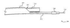
- FIG. 3Ashows laser catheter 300 according to another embodiment of the invention.
- Laser catheter 300can include a catheter body 205 (or sheath) within which a fiber optic bundle 210 (or any other light guide) is disposed.
- Fiber optic bundlecan include any number of optical fibers and, in some embodiments, can include a separate sheath.
- Catheter body 205can include a distal end and a proximal end.
- the proximal end of catheter body 205can include a coupler that is configured to couple with a laser source as shown in FIG. 1 .
- the proximal end of the fiber optic bundlecan also be coupled with the coupler in order to receive and conduct laser light through the optical fibers.
- Fiber optic bundlecan include a marker band 211 at the distal tip of the fiber optic bundle that can include any number of sizes and/or shapes.
- Marker band 211can include a radiopaque material.
- Catheter body 205can include tip 213 , that extends from opening 207 .
- tip 213can be coupled with catheter body 205 .
- tip 213can be integral with catheter body 205 .
- tip 213can support the distal end of fiber optic bundle 210 .
- Fiber optic bundle 205can include a guidewire lumen that extends through a portion of the catheter body.
- guidewire 215can be positioned within a vessel, laser catheter 200 can be threaded over guidewire 215 using the guidewire lumen in order to direct the catheter through a vessel toward a target.
- guidewire lumencan extend through at least a portion of tip 213 .
- Retaining wire 216can extend from the distal tip of fiber optic bundle 210 and be coupled with tip 213 .
- retaining wire 216 and guidewirecan be the same wire.
- tip 213can also include an imaging device 260 disposed at the distal end of tip 213 .
- Imaging device 260can be located at least 0.4, 0.5, 0.6, 0.7, 0.8, 0.9, 1.0 cm longitudinally (or forward) from the distal end (or exit aperture) of fiber optic bundle 210 . Any type of imaging device can be used.
- Imaging device 260can include any ultrasound sensor or laser interferometry device.
- a laser interferometry devicecan include a plurality of fiber optics with an exit aperture disposed near the distal end of the laser catheter and extending through a sheath of the catheter.
- Imaging device 260for example, can be formed cylindrically around tip 213 as a patch, or a ring. In some embodiments, imaging device 260 can include any shape or size.
- balloon 227can be disposed between fiber optic bundle 210 and tip 213 .
- Balloon 227can be coupled with a balloon tube that can be used to inflate and/or deflate the balloon.
- Balloon tubecan extend proximally through at least a portion of catheter body 205 .
- a balloon tube couplercan be provided that allows a doctor to attach a syringe (or other device) that can be activated to inflate and/or deflate the balloon.
- FIG. 3Bshows an example of laser catheter 300 with balloon 227 inflated. As seen, balloon 227 can be inflated in order to laterally shift the exit aperture of fiber optic bundle 210 relative to tip 213 .
- FIG. 4Ashows a cross section of catheter 300 along line A-A according to some embodiments.
- catheter body 205surrounds a plurality of fiber optics 217 , guidewire lumen 240 , balloon tube 230 , and imaging wire bundle 235 .
- balloon tube 230can have an outside diameter of about 0.008, 0.009, 0.010. 0.011, 0.012, 0.013, 0.014, or 0.015 inches. Any of these components may be included in a different combination or order, or excluded altogether.
- Guidewire 215is shown within guidewire lumen 240 .
- balloon tube 235 and/or guidewire lumen 230can be disposed within a sheath and/or a tube.
- FIG. 4Bshows a cross section of catheter 200 along line B-B according to some embodiments.
- tip 213includes balloon 206 in a deflated state.
- balloon tube 230terminates within or at the boundary of balloon 206 .
- balloon tube 230can terminate at a number of different positions within balloon 206 .
- Imaging wire bundle 235extends through balloon 206 .
- the junctions of imaging wire bundle 235 and balloon 206can be sealed to ensure balloon inflates without a leak at the junction.
- Guidewire lumen 240is placed concentrically within catheter body 205 .
- guidewire lumen 240can be located anywhere within catheter body 205 , for example, guidewire lumen can be disposed eccentrically with catheter body (e.g., as shown in FIG. 6B ). In some embodiments, guidewire lumen 230 can extend through balloon when a retaining wire is used.
- FIG. 4Cshows a cross section of catheter 200 along line C-C according to some embodiments.
- balloon tube 230terminated within balloon 206 and only wire bundle 235 is found within balloon 206 .
- FIG. 4Dis a cross section of catheter 200 along line D-D showing imaging wire bundle 230 extending through tip 213 distal from balloon 206 according to some embodiments.
- guidewire lumen 230can extend through balloon when a retaining wire is used.
- FIG. 4Eis a cross section of catheter 200 along line E-E.
- Line E-Eis distal relative to probe 260 .
- distal tip portion 207only includes guidewire lumen 240 .
- distal tip portion 207can have an inside diameter similar or slightly larger than the outside diameter of guidewire lumen 240 .
- FIG. 4Fshows a cross section of catheter 210 in FIG. 3B along line F-F. Imaging wire bundle 235 is shown passing through balloon 206 while inflated.
- catheter body 205may have a diameter of approximately 2.0 mm.
- Each fibers 217may be less than about 0.1 mm.
- the fibersmay be less than about 0.05 mm.
- the fiber opticsmay be contained within bundle 210 .
- bundle 210can be about 1.0 mm by about 2.0 mm.
- Guidewire lumen 230can have an inside diameter of approximately 0.024 inches and inside diameter of approximately 0.018 inches. In other embodiments, guidewire lumen 230 may have an outside diameter less than about 0.025 inches and/or an inside diameter less than about 0.02 inches.
- any type of light guidecan be used.
- a liquid light guide and or a solid light guidecan be used in place of the fiber optic bundle without limitation.
- FIG. 5Ashows a side view of laser catheter 500 with ramp 505 according to one embodiment of the invention.
- Imaging device 260can be found at the distal tip of the catheter body 205 forward (more distal) than the distal tip of fiber optic bundle 210 .
- Fiber optic bundle 210can be located at a first position relative to ramp 505 and can extend from aperture 207 of catheter body 205 .
- Fiber optic bundlecan be actuated forward into a second position as shown in FIG. 5B , such that distal end of fiber optic bundle 210 has actuated distally up and past ramp 505 toward the distal end of catheter 500 .
- Retaining wire 216can provide a restraining force on the distal end of fiber optic bundle 210 in order to keep the distal end substantially parallel with catheter body 205 while in the second position.
- guidewire 215can extend through a guidewire lumen through catheter body 205 .
- retaining wire 216 and guidewire 215can be the same wire.
- retaining wire 216may be detachably coupled with either or both distal tip 213 and/or light guide 210 .
- retaining wire 216may be connected with the distal tip using solder, clamps, glue, fused, etc.
- retaining wireis soldered with radiopaque marker band 211 .
- retaining wire 216may be coiled around the distal tip and glued or fused with distal tip 213 .
- retaining wire 216may be sandwiched between distal tip 213 and radiopaque marker band 211 .
- retaining wire 216may extend through a portion of light guide 210 .
- retaining wire 216may extend through light guide 210 next to and/or with a plurality of optical fibers. Retaining wire 216 may aid in retaining the position and/or bias of the light guide when light guide is extended up ramp 505 . Retaining wire 216 may also aid in providing the proper bias when light guide is extended up ramp 505 .
- retaining wire 216may be lengthened and/or include elasticity such that biasing catheter may be more or less biased when light guide is extended up ramp 505 .
- retaining wireprovides resistance to light guide 210 when balloon 705 is inflated and/or when light guide is extended up ramp 505 , which may align light guide 210 parallel with distal tip 213 and/or catheter body 205 .
- biasing laser catheterscan be used.
- laser catheters described in U.S. Pat. No. 7,572,254, entitled “Rapid Exchange Bias Laser Catheter Design,” which is incorporated herein by reference in its entirety,can be used in conjunction with various aspects described herein.
- FIG. 6Ashows a cross section of catheter 500 along line A-A.
- Catheter body 205surrounds a number of fiber optics 217 , guidewire lumen 240 , and imaging wire bundle 235 . Any of these components may be included in a different combination, order, or excluded altogether.
- guidewire lumen 240can be positioned at any position within the catheter body.
- balloon tube 235 and/or guidewire lumen 230can be disposed within a sheath and/or a tube.
- fiber optics 217 and/or guidewire lumen 240can be bundled within a sheath. Thus, when the fiber optic bundle is actuated forward fiber optics 217 do not tangle with balloon lumen 235 .
- balloon lumenin some embodiments, can be embedded within catheter body 205 .
- FIG. 6Bshows a cross section of catheter 500 along line B-B.
- guidewire lumen 217is arranged eccentrically within fiber optic bundle 210 as shown in the figure.
- Guidewire 215is shown within guidewire lumen 240 .
- guidewire lumen 240can be located anywhere within catheter body 205 , for example, guidewire lumen can be disposed concentrically within catheter body (e.g., as shown in FIG. 2B ).
- Imaging wire bundle 235also extends through this portion of catheter 500 .
- FIG. 6Cshows a cross section of catheter 500 along line C-C.
- This portion of catheter 500includes tip 213 that extend more distally from aperture 207 and proximal to imaging device 260 .
- Imaging wire bundle 235also extends through this portion of catheter 500 .
- FIG. 6Dshows a cross section of catheter 500 along line D-D. This portion of catheter 500 is distal with respect to imaging device 260 and only the guidewire lumen 240 extends through this portion.
- FIG. 6Eshows a cross section of catheter 500 along line E-E showing fiber optic bundle 210 having been actuated up the ramp as shown in FIG. 5B .
- FIG. 7Ashows a side view of balloon catheter 700 with balloon 705 deflated according to another embodiment of the invention.
- balloon catheter 700is somewhat similar to catheter 200 shown in FIG. 3A .
- balloon catheter 700differs from catheter 200 in that balloon 705 inflates radially as shown in FIG. 7B .
- a physiciancan oblate blockage within a vessel (e.g., a human artery) using catheter 700 .
- Catheter 700can be positioned in front of the blockage with balloon 705 deflated. The laser can then be activated. During lasing catheter 700 can ablate a central portion of the blockage roughly the size of the exit aperture of catheter 210 .
- balloon 705can be inflated and pressed against an interior wall within the vessel.
- the pressure against the interior wallcan shift the exit aperture of catheter 210 toward the opposite interior wall within the vessel allowing catheter 700 to ablate material near the vessel wall by activating the laser.
- Catheter 700can be rotated by the physician in order to ablate the material near other portions of the interior wall of the vessel.
- catheter 700can include imaging device 260 and in other embodiments imaging device 206 can be excluded. Similarly, catheters in some embodiments can include radiopaque band 211 , while catheters in other embodiments do not.
- FIG. 8is a side view of balloon biasing catheter 800 according to one embodiment.
- a balloon biasing cathetermay include a catheter body 205 (or elongated housing) with a light guide 210 disposed within a lumen of catheter body 205 and extending from an aperture within catheter body 205 .
- light guide 210may include a plurality of fiber optics.
- the light guidemay be a liquid light guide and/or a combination of a liquid light guide and a fiber optic light guide.
- the light guideis free to slide within the lumen of the catheter body.
- the light guide lumenmay slide relative to the catheter body.
- the light guidemay be fixed within the lumen of the catheter body.
- Light guide 210may be located within catheter body 205 and may extend from the proximal end of the catheter body to the distal end of the catheter body. At the proximal end of the catheter body, light guide 210 may terminate with laser coupler 715 .
- the light guide lumenmay include an aperture at or near the distal end of catheter body 205 from which light guide 210 may extend. In some embodiments, light guide 210 may extend 1-10 mm from the aperture. In some embodiments, light guide 210 may also include a radiopaque marker band 211 near the distal end.
- a balloon biasing cathetermay also include a guidewire lumen.
- the guidewire lumenmay be configured to allow a guidewire to pass and/or slide therethrough.
- the guidewire lumenmay extend, for example, from distal guidewire port through a portion of catheter body 205 .
- the guidewire lumenmay extend to or near the proximal end of catheter body 205 .
- guidewire lumenmay extend from the distal end to a position proximal with the light guide aperture and/or proximal with balloon 227 .
- the guidewire lumenmay be configured to accept a guidewire and allow the guidewire to slide within the guidewire lumen.
- Proximal guidewire port 720may be located anywhere along catheter body 205 .
- catheter 800can include balloon tube port 725 that can be coupled with balloon 227 via a balloon tube (e.g. balloon tube 230 ).
- balloon lumenmay couple with a luer fitting at balloon tube port 725 .
- Balloon tube port 725can be configured to accept any type of syringe or pump that can pressurize and depressurize balloon 227 .
- the inner diameter of balloon lumenmay be approximately 0.001 inches.
- the inner diameter of the balloon lumen (or tube)may be between 0.0005 and 0.01 inches.
- the outside diameter of the balloon lumenfor example, may be 0.016 inches. In some embodiments, the outside diameter of the balloon lumen may be 0.05 to 0.005 inches.
- the balloonmay be coupled with a syringe or an indeflator.
- Balloon 705may be inflated by injecting fluid through balloon lumen using either a syringe or an indeflator.
- the balloonmay be inflated using a contrast agent fluid or saline solution.
- the balloon lumen 1813may include any type of plastic tubing known in the art.
- balloon lumen 1813may comprise nylon, Teflon, polyethylene, etc.
- Guidewire lumen port 720can also be included. Guidewire lumen port 720 can be coupled with guidewire lumen 240 and can allow a guidewire to extend through the distal end toward the proximal end of the catheter. A bifurcated cover can be used to separate the ports from the body of the catheter.
- FIG. 9Ashows a cutaway of a balloon biasing catheter in use within vessel 810 near target 805 .
- the balloon biasing cathetermay be inserted into vessel 810 by following guidewire 215 that may have been previously placed within vessel 810 .
- Guidewire 215may run through the guidewire lumen as shown in the figure.
- Balloon 705is deflated in FIG. 9A .
- Light guide 210may be activated and a portion of target 215 may be ablated.
- FIG. 18Bshows results of ablation of target 805 with the balloon biasing catheter positioned as shown in FIG. 9A .
- Target 805may not be completely ablated leaving portions 806 , 807 .
- a hole within target 805may result.
- FIG. 9Bshows light guide 210 biased axially by inflating balloon 705 .
- balloon 705When balloon 705 is inflated, the laser catheter can be axially biased toward target portion 807 .
- balloon 705may be partially or fully inflated as needed to align light guide 210 with target portion 807 .
- FIG. 10Ashows a resulting example of ablation using the configuration in FIG. 9B .
- Target portion 807has been at least partially ablated. In some embodiments, target portion 807 may be completely ablated.
- balloon 705can be deflated and the catheter rotated within vessel 810 as shown in FIG. 10A .
- balloon 705can be inflated positioning light guide 210 toward target portion 806 .
- balloon 705may remain inflated during rotation.
- balloon biasing catheter and/or guidewire 215may be advanced during any of the ablation steps.
- balloon biasing cathetermay be rotated 90° or any other angle in order to ablate other target portions and/or material near or adhering to a vessel wall.
- imaging of the interior of vessel 810can occur using imaging device 260 .
- laser catheterscan include a balloon (e.g., balloon 705 ).
- balloonscan have a diameter of about 1 mm to 3 mm when inflated.
- balloonmay have an inflated diameter up to about 5 mm and as little as 0.5 mm.
- the balloonmay comprise a portion of tubing with a sealed distal end.
- a portion of tubingmay form the balloon and have thinner walls and/or a larger diameter such that the balloon portion of the tubing inflates under pressure.
- a balloonfor example, may comprise any type of plastic, for example, the balloon may comprise nylon, Teflon, polyethylene, etc.
- a balloonin some embodiments, may extend the entire length of distal tip 213 .
- balloon 705may be 10 cm, 9 cm, 8 cm, 7 cm, 6 cm, 5 cm, 4 cm, 3 cm, 2 cm, or 1 cm in length.
- a ballooncan be used to deflect a light guide, fiber optic bundle and/or catheter body.
- the balloonmay deflect the light guide, fiber optic bundle and/or catheter body 205 1.0 mm.
- the light guide, fiber optic bundle and/or catheter bodymay be biased 0.5 mm, 1.5 mm, 2.0 mm, 2.5 mm, 3.0 mm etc. from a deflated position.
- the balloon biasing cathetermay ablate a larger diameter area than if the light guide is not biased.
- FIG. 11shows a flowchart of a process for using a biasing catheter according to one embodiment.
- Various other processesmay be used that add to or take away from the process shown in FIG. 11 and described below.
- the proximal end of a guidewireis inserted through the distal guidewire port at the distal tip of the balloon biasing catheter at block 1005 .
- the balloon biasing cathetermay then be inserted into a vessel at block 1010 and slid over the guidewire and positioned near a target at block 1015 .
- the lasermay be activated ablating a portion of the target area.
- the balloon biasing cathetermay be advanced at block 1023 . Once ablation is complete, the laser is deactivated at block 1025 .
- the balloonmay be inflated at block 1030 .
- the distal tip of the balloon biasing cathetermay be radially biased yet substantially parallel with the balloon biasing catheter and positioned to ablate unablated portions of the target.
- the lasermay again be activated at block 1035 and portions of the target ablated.
- the balloon biasing cathetermay be advanced toward the target.
- the laseris deactivated after a period of time and the balloon deflated at block 1045 . If the ablation area is satisfactory and no more ablation is required as decided at block 1050 the balloon biasing catheter is removed at block 1060 . However, if more ablation is required, the balloon biasing catheter may be rotated axially within the vessel at block 1055 and the process returns to block 1030 .
- FIG. 12shows a flowchart of a process for using a biasing catheter according to one embodiment.
- This flow chartis substantially similar to the flowchart shown in FIG. 11 .
- the light guideis advanced relative to the balloon biasing catheter.
- the catheter bodyremains substantially still as the light guide is advanced to ablate target material.
- FIG. 11 and FIG. 12are described in conjunction with a balloon biasing catheter, other types of biasing catheters can be used.
- biasing catheters as those shown in FIG. 5Acan also be used.
- FIG. 13is a flowchart describing another embodiment for using a biasing catheter in conjunction with an imaging device.
- Blocks 1005 , 1010 , and 1015are similar to those described above in conjunction with FIG. 11 .
- the interior of the vesselcan be imaged using an imaging device (e.g., an ICUS/IVUS device).
- an imaging devicee.g., an ICUS/IVUS device.
- the image of the interior of the vesselcan be displayed on a display (e.g., the display associated with computer 180 shown in FIG. 1 ) such that a physician or doctor can view the interior of the vessel.
- the doctorcan reposition the laser catheter.
- the filteringcan occur in real time. In other embodiments, the filtering can occur after the imaging has occurred. In some embodiments, filtering can occur by disabling the imaging device while the laser is activated. Moreover, imaging can be filtered for an extended period of time beyond the time the laser is activated. Filtering can also occur at a display, such that, images produced while the laser is activated are not displayed to a user. If the laser is not activated at block 1215 , the interior of the vessel can continued to be imaged at block 1210 .
- an imaging devicein conjunction with a laser catheter.
- the imaging devicecan include an ultrasound sensor or a laser interferometry device.
- a laser interferometry devicecan include a plurality of fiber optics with an exit aperture disposed near the distal end of the laser catheter and extending through a sheath of the catheter.
- the imaging devicefor example, can be formed cylindrically, as a patch, or a ring.
- An ultrasound devicecan include an Intracoronary/Intravascular Ultrasound (ICUS/IVUS) device that can employ very small transducers arranged on a catheter and provides electronic transduced echo signals to an external imaging system in order to produce a two or three-dimensional image of the lumen, the arterial tissue, plaque, blockages, and/or tissue surrounding the artery. These images can be generated in substantially real time and can provide images of superior quality to the known x-ray imaging methods and apparatuses. Other imaging methods and intravascular ultrasound imaging applications would also benefit from enhanced image resolution.
- An ultrasound devicefor example, can include a flexible polyimide film layer.
- imagingcan be gated while the laser catheter is pulsing.
- Signal processing techniquescan be implemented (e.g. at computer 180 in FIG. 1 ) that filters out optical, mechanical, and electronic interference effects.
- An electron plasmacan be created within the vessel during ablation. This electron plasma can interfere with imaging from an imaging device (e.g. imaging device 260 ).
- electromagnetic interferencecan be avoided by filtering out data during the set time period while the laser is pulsing.
- filteringcan occur for a longer duration such as for a period greater than the pulsing period. For example, filtering can occur 30%, 40%, 50%, 60%, or 70% longer than the laser pulsing period in order to filter out any latent electromagnetic interference. For example, if the laser pulses laser light for 135 ns, filtering can eliminate imaging data during the 200 ns after the beginning of the pulse and/or data capture can be delayed for 200 ns after the beginning of the pulse.
- imaging data recorded using a forward imaging devicecan also include filtering data recorded 0.4, 0.5, 0.6, 0.7, 0.8, 1.0, 1.1, 1.2, 1.3 or 1.4 ms after the laser pulse has begun.
- signal captureor data retention
- Delaying signal capture until 1 ms after the laser pulsestill allows for a better than 10 frames per second data acquisition and signal processing even operating at 80 Hz.
- elimination of data using filtering techniquescan be implemented in software operating at computer 180 .
- dedicated electrical circuitrycan be used to filter the data after the data has been received.
- data filteringcan occur well after the imaging data has been captured and recorded.
- filteringcan occur in real time. That is, for example, the data from the imaging device can be ignored, deleted, or not displayed while the laser is active and/or during some post activation time period.
- the imaging devicecan be disabled during filtering periods.
- gatingcan prevent images from being displayed on a display (e.g., a display associated with computer 180 shown in FIG. 1 ) while the laser catheter is activated.
- the lasercan be electrically, mechanically, or optically interrupted to allow for data acquisition.
- imagingcan occur at predetermined intervals during which laser pulses are stopped to allow for better imaging.
- imagingcan be initiated by a doctor or technician.
- the lasercan be deactivated to allow for better imaging.
- the lasercan be reactivated and pulsing can recommence (whether automatically or manually).
- Circuits, logic modules, processors, and/or other componentsmay be described herein as being “configured” to perform various operations. Those skilled in the art will recognize that, depending on implementation, such configuration can be accomplished through design, setup, interconnection, and/or programming of the particular components and that, again depending on implementation, a configured component might or might not be reconfigurable for a different operation.
- a programmable processorcan be configured by providing suitable executable code; a dedicated logic circuit can be configured by suitably connecting logic gates and other circuit elements; and so on.
- Computer programs incorporating various features of the present inventionmay be encoded on various computer readable storage media; suitable media include magnetic disk or tape, optical storage media such as compact disk (CD) or digital versatile disk (DVD), flash memory, and the like.
- Computer readable storage media encoded with the program codemay be packaged with a compatible device or provided separately from other devices.
- program codemay be encoded and transmitted via wired optical, and/or wireless networks conforming to a variety of protocols, including the Internet, thereby allowing distribution, e.g., via Internet download.
Landscapes
- Health & Medical Sciences (AREA)
- Life Sciences & Earth Sciences (AREA)
- Surgery (AREA)
- Physics & Mathematics (AREA)
- Biomedical Technology (AREA)
- Molecular Biology (AREA)
- Veterinary Medicine (AREA)
- Public Health (AREA)
- General Health & Medical Sciences (AREA)
- Engineering & Computer Science (AREA)
- Animal Behavior & Ethology (AREA)
- Heart & Thoracic Surgery (AREA)
- Medical Informatics (AREA)
- Nuclear Medicine, Radiotherapy & Molecular Imaging (AREA)
- Vascular Medicine (AREA)
- Optics & Photonics (AREA)
- Electromagnetism (AREA)
- Otolaryngology (AREA)
- Biophysics (AREA)
- Pathology (AREA)
- Radiology & Medical Imaging (AREA)
- Laser Surgery Devices (AREA)
- Media Introduction/Drainage Providing Device (AREA)
Abstract
Description
Claims (14)
Priority Applications (4)
| Application Number | Priority Date | Filing Date | Title |
|---|---|---|---|
| US12/649,759US8545488B2 (en) | 2004-09-17 | 2009-12-30 | Cardiovascular imaging system |
| US13/968,993US20130338500A1 (en) | 2004-09-17 | 2013-08-16 | Cardiovascular imaging system |
| US15/922,636US10959699B2 (en) | 2004-09-17 | 2018-03-15 | Cardiovascular imaging system |
| US16/297,685US20190200953A1 (en) | 2004-09-17 | 2019-03-10 | Cardiovascular imaging system |
Applications Claiming Priority (4)
| Application Number | Priority Date | Filing Date | Title |
|---|---|---|---|
| US61119104P | 2004-09-17 | 2004-09-17 | |
| US11/228,845US7572254B2 (en) | 2004-09-17 | 2005-09-16 | Apparatus and methods for directional delivery of laser energy |
| US12/337,232US8628519B2 (en) | 2004-09-17 | 2008-12-17 | Rapid exchange bias laser catheter design |
| US12/649,759US8545488B2 (en) | 2004-09-17 | 2009-12-30 | Cardiovascular imaging system |
Related Parent Applications (1)
| Application Number | Title | Priority Date | Filing Date |
|---|---|---|---|
| US12/337,232Continuation-In-PartUS8628519B2 (en) | 2004-09-17 | 2008-12-17 | Rapid exchange bias laser catheter design |
Related Child Applications (1)
| Application Number | Title | Priority Date | Filing Date |
|---|---|---|---|
| US13/968,993DivisionUS20130338500A1 (en) | 2004-09-17 | 2013-08-16 | Cardiovascular imaging system |
Publications (2)
| Publication Number | Publication Date |
|---|---|
| US20110009750A1 US20110009750A1 (en) | 2011-01-13 |
| US8545488B2true US8545488B2 (en) | 2013-10-01 |
Family
ID=43428003
Family Applications (4)
| Application Number | Title | Priority Date | Filing Date |
|---|---|---|---|
| US12/649,759Active2027-05-21US8545488B2 (en) | 2004-09-17 | 2009-12-30 | Cardiovascular imaging system |
| US13/968,993AbandonedUS20130338500A1 (en) | 2004-09-17 | 2013-08-16 | Cardiovascular imaging system |
| US15/922,636Active2026-04-14US10959699B2 (en) | 2004-09-17 | 2018-03-15 | Cardiovascular imaging system |
| US16/297,685AbandonedUS20190200953A1 (en) | 2004-09-17 | 2019-03-10 | Cardiovascular imaging system |
Family Applications After (3)
| Application Number | Title | Priority Date | Filing Date |
|---|---|---|---|
| US13/968,993AbandonedUS20130338500A1 (en) | 2004-09-17 | 2013-08-16 | Cardiovascular imaging system |
| US15/922,636Active2026-04-14US10959699B2 (en) | 2004-09-17 | 2018-03-15 | Cardiovascular imaging system |
| US16/297,685AbandonedUS20190200953A1 (en) | 2004-09-17 | 2019-03-10 | Cardiovascular imaging system |
Country Status (1)
| Country | Link |
|---|---|
| US (4) | US8545488B2 (en) |
Cited By (11)
| Publication number | Priority date | Publication date | Assignee | Title |
|---|---|---|---|---|
| US9308047B2 (en) | 2004-09-17 | 2016-04-12 | The Spectranetics Corporation | Rapid exchange bias laser catheter design |
| US9623211B2 (en) | 2013-03-13 | 2017-04-18 | The Spectranetics Corporation | Catheter movement control |
| US9757200B2 (en) | 2013-03-14 | 2017-09-12 | The Spectranetics Corporation | Intelligent catheter |
| US10646274B2 (en) | 2014-12-30 | 2020-05-12 | Regents Of The University Of Minnesota | Laser catheter with use of reflected light and force indication to determine material type in vascular system |
| US10646275B2 (en) | 2014-12-30 | 2020-05-12 | Regents Of The University Of Minnesota | Laser catheter with use of determined material type in vascular system in ablation of material |
| US10646118B2 (en) | 2014-12-30 | 2020-05-12 | Regents Of The University Of Minnesota | Laser catheter with use of reflected light to determine material type in vascular system |
| US10758308B2 (en) | 2013-03-14 | 2020-09-01 | The Spectranetics Corporation | Controller to select optical channel parameters in a catheter |
| US10772683B2 (en) | 2014-05-18 | 2020-09-15 | Eximo Medical Ltd. | System for tissue ablation using pulsed laser |
| US10959699B2 (en) | 2004-09-17 | 2021-03-30 | The Spectranetics Corporation | Cardiovascular imaging system |
| US10987168B2 (en) | 2014-05-29 | 2021-04-27 | Spectranetics Llc | System and method for coordinated laser delivery and imaging |
| US11642169B2 (en) | 2013-03-14 | 2023-05-09 | The Spectranetics Corporation | Smart multiplexed medical laser system |
Families Citing this family (87)
| Publication number | Priority date | Publication date | Assignee | Title |
|---|---|---|---|---|
| US8347891B2 (en) | 2002-04-08 | 2013-01-08 | Medtronic Ardian Luxembourg S.A.R.L. | Methods and apparatus for performing a non-continuous circumferential treatment of a body lumen |
| US7756583B2 (en) | 2002-04-08 | 2010-07-13 | Ardian, Inc. | Methods and apparatus for intravascularly-induced neuromodulation |
| DE202004021953U1 (en) | 2003-09-12 | 2013-06-19 | Vessix Vascular, Inc. | Selectable eccentric remodeling and / or ablation of atherosclerotic material |
| US9713730B2 (en) | 2004-09-10 | 2017-07-25 | Boston Scientific Scimed, Inc. | Apparatus and method for treatment of in-stent restenosis |
| US8396548B2 (en) | 2008-11-14 | 2013-03-12 | Vessix Vascular, Inc. | Selective drug delivery in a lumen |
| US8019435B2 (en) | 2006-05-02 | 2011-09-13 | Boston Scientific Scimed, Inc. | Control of arterial smooth muscle tone |
| JP5559539B2 (en) | 2006-10-18 | 2014-07-23 | べシックス・バスキュラー・インコーポレイテッド | System that induces desirable temperature effects on body tissue |
| EP2455036B1 (en) | 2006-10-18 | 2015-07-15 | Vessix Vascular, Inc. | Tuned RF energy and electrical tissue characterization for selective treatment of target tissues |
| EP2076198A4 (en) | 2006-10-18 | 2009-12-09 | Minnow Medical Inc | Inducing desirable temperature effects on body tissue |
| EP2355737B1 (en) | 2008-11-17 | 2021-08-11 | Boston Scientific Scimed, Inc. | Selective accumulation of energy without knowledge of tissue topography |
| WO2011126580A2 (en) | 2010-04-09 | 2011-10-13 | Minnow Medical, Inc. | Power generating and control apparatus for the treatment of tissue |
| US9192790B2 (en) | 2010-04-14 | 2015-11-24 | Boston Scientific Scimed, Inc. | Focused ultrasonic renal denervation |
| US8473067B2 (en) | 2010-06-11 | 2013-06-25 | Boston Scientific Scimed, Inc. | Renal denervation and stimulation employing wireless vascular energy transfer arrangement |
| US9155589B2 (en) | 2010-07-30 | 2015-10-13 | Boston Scientific Scimed, Inc. | Sequential activation RF electrode set for renal nerve ablation |
| US9408661B2 (en) | 2010-07-30 | 2016-08-09 | Patrick A. Haverkost | RF electrodes on multiple flexible wires for renal nerve ablation |
| US9358365B2 (en) | 2010-07-30 | 2016-06-07 | Boston Scientific Scimed, Inc. | Precision electrode movement control for renal nerve ablation |
| US9463062B2 (en) | 2010-07-30 | 2016-10-11 | Boston Scientific Scimed, Inc. | Cooled conductive balloon RF catheter for renal nerve ablation |
| US9084609B2 (en) | 2010-07-30 | 2015-07-21 | Boston Scientific Scime, Inc. | Spiral balloon catheter for renal nerve ablation |
| US8974451B2 (en) | 2010-10-25 | 2015-03-10 | Boston Scientific Scimed, Inc. | Renal nerve ablation using conductive fluid jet and RF energy |
| US9220558B2 (en) | 2010-10-27 | 2015-12-29 | Boston Scientific Scimed, Inc. | RF renal denervation catheter with multiple independent electrodes |
| US9028485B2 (en) | 2010-11-15 | 2015-05-12 | Boston Scientific Scimed, Inc. | Self-expanding cooling electrode for renal nerve ablation |
| US9668811B2 (en) | 2010-11-16 | 2017-06-06 | Boston Scientific Scimed, Inc. | Minimally invasive access for renal nerve ablation |
| US9089350B2 (en) | 2010-11-16 | 2015-07-28 | Boston Scientific Scimed, Inc. | Renal denervation catheter with RF electrode and integral contrast dye injection arrangement |
| US9326751B2 (en) | 2010-11-17 | 2016-05-03 | Boston Scientific Scimed, Inc. | Catheter guidance of external energy for renal denervation |
| US9060761B2 (en) | 2010-11-18 | 2015-06-23 | Boston Scientific Scime, Inc. | Catheter-focused magnetic field induced renal nerve ablation |
| US9023034B2 (en) | 2010-11-22 | 2015-05-05 | Boston Scientific Scimed, Inc. | Renal ablation electrode with force-activatable conduction apparatus |
| US9192435B2 (en) | 2010-11-22 | 2015-11-24 | Boston Scientific Scimed, Inc. | Renal denervation catheter with cooled RF electrode |
| US20120157993A1 (en) | 2010-12-15 | 2012-06-21 | Jenson Mark L | Bipolar Off-Wall Electrode Device for Renal Nerve Ablation |
| US9220561B2 (en) | 2011-01-19 | 2015-12-29 | Boston Scientific Scimed, Inc. | Guide-compatible large-electrode catheter for renal nerve ablation with reduced arterial injury |
| JP5759615B2 (en) | 2011-04-08 | 2015-08-05 | コヴィディエン リミテッド パートナーシップ | Iontophoretic catheter system and method for renal sympathetic denervation and iontophoretic drug delivery |
| WO2012148969A2 (en) | 2011-04-25 | 2012-11-01 | Brian Kelly | Apparatus and methods related to constrained deployment of cryogenic balloons for limited cryogenic ablation of vessel walls |
| CN103813745B (en) | 2011-07-20 | 2016-06-29 | 波士顿科学西美德公司 | In order to visualize, be directed at and to melt transcutaneous device and the method for nerve |
| EP2734264B1 (en) | 2011-07-22 | 2018-11-21 | Boston Scientific Scimed, Inc. | Nerve modulation system with a nerve modulation element positionable in a helical guide |
| WO2013055826A1 (en) | 2011-10-10 | 2013-04-18 | Boston Scientific Scimed, Inc. | Medical devices including ablation electrodes |
| EP2765940B1 (en) | 2011-10-11 | 2015-08-26 | Boston Scientific Scimed, Inc. | Off-wall electrode device for nerve modulation |
| US9420955B2 (en) | 2011-10-11 | 2016-08-23 | Boston Scientific Scimed, Inc. | Intravascular temperature monitoring system and method |
| US9364284B2 (en) | 2011-10-12 | 2016-06-14 | Boston Scientific Scimed, Inc. | Method of making an off-wall spacer cage |
| US9162046B2 (en) | 2011-10-18 | 2015-10-20 | Boston Scientific Scimed, Inc. | Deflectable medical devices |
| EP2768568B1 (en) | 2011-10-18 | 2020-05-06 | Boston Scientific Scimed, Inc. | Integrated crossing balloon catheter |
| US8951251B2 (en) | 2011-11-08 | 2015-02-10 | Boston Scientific Scimed, Inc. | Ostial renal nerve ablation |
| WO2013074813A1 (en) | 2011-11-15 | 2013-05-23 | Boston Scientific Scimed, Inc. | Device and methods for renal nerve modulation monitoring |
| US9119632B2 (en) | 2011-11-21 | 2015-09-01 | Boston Scientific Scimed, Inc. | Deflectable renal nerve ablation catheter |
| US9265969B2 (en) | 2011-12-21 | 2016-02-23 | Cardiac Pacemakers, Inc. | Methods for modulating cell function |
| US9028472B2 (en) | 2011-12-23 | 2015-05-12 | Vessix Vascular, Inc. | Methods and apparatuses for remodeling tissue of or adjacent to a body passage |
| EP2797534A1 (en) | 2011-12-28 | 2014-11-05 | Boston Scientific Scimed, Inc. | Device and methods for nerve modulation using a novel ablation catheter with polymeric ablative elements |
| US9050106B2 (en) | 2011-12-29 | 2015-06-09 | Boston Scientific Scimed, Inc. | Off-wall electrode device and methods for nerve modulation |
| US10660703B2 (en) | 2012-05-08 | 2020-05-26 | Boston Scientific Scimed, Inc. | Renal nerve modulation devices |
| US9717475B2 (en)* | 2012-05-11 | 2017-08-01 | Volcano Corporation | Ultrasound catheter for imaging and blood flow measurement |
| WO2013177577A2 (en)* | 2012-05-25 | 2013-11-28 | Eberle Michael J | Optical fiber pressure sensor |
| US10321946B2 (en) | 2012-08-24 | 2019-06-18 | Boston Scientific Scimed, Inc. | Renal nerve modulation devices with weeping RF ablation balloons |
| CN104780859B (en) | 2012-09-17 | 2017-07-25 | 波士顿科学西美德公司 | Self-positioning electrode systems and methods for renal neuromodulation |
| US10398464B2 (en) | 2012-09-21 | 2019-09-03 | Boston Scientific Scimed, Inc. | System for nerve modulation and innocuous thermal gradient nerve block |
| US10549127B2 (en) | 2012-09-21 | 2020-02-04 | Boston Scientific Scimed, Inc. | Self-cooling ultrasound ablation catheter |
| CN104869930B (en) | 2012-10-10 | 2020-12-25 | 波士顿科学国际有限公司 | Renal neuromodulation apparatus and methods |
| WO2014163987A1 (en) | 2013-03-11 | 2014-10-09 | Boston Scientific Scimed, Inc. | Medical devices for modulating nerves |
| WO2014143571A1 (en) | 2013-03-11 | 2014-09-18 | Boston Scientific Scimed, Inc. | Medical devices for modulating nerves |
| US9808311B2 (en) | 2013-03-13 | 2017-11-07 | Boston Scientific Scimed, Inc. | Deflectable medical devices |
| EP2967734B1 (en) | 2013-03-15 | 2019-05-15 | Boston Scientific Scimed, Inc. | Methods and apparatuses for remodeling tissue of or adjacent to a body passage |
| US10265122B2 (en) | 2013-03-15 | 2019-04-23 | Boston Scientific Scimed, Inc. | Nerve ablation devices and related methods of use |
| EP2968919B1 (en) | 2013-03-15 | 2021-08-25 | Medtronic Ardian Luxembourg S.à.r.l. | Controlled neuromodulation systems |
| CN105228546B (en) | 2013-03-15 | 2017-11-14 | 波士顿科学国际有限公司 | Medical devices and methods for treating hypertension utilizing impedance compensation |
| US20140370251A1 (en)* | 2013-06-18 | 2014-12-18 | Junius, LLC | Flame Retardant Identification System |
| CN105473092B (en) | 2013-06-21 | 2019-05-17 | 波士顿科学国际有限公司 | The medical instrument for renal nerve ablation with rotatable shaft |
| CN105473091B (en) | 2013-06-21 | 2020-01-21 | 波士顿科学国际有限公司 | Renal denervation balloon catheter with co-movable electrode supports |
| US9707036B2 (en) | 2013-06-25 | 2017-07-18 | Boston Scientific Scimed, Inc. | Devices and methods for nerve modulation using localized indifferent electrodes |
| CN105358084B (en) | 2013-07-01 | 2018-11-09 | 波士顿科学国际有限公司 | Medical instrument for renal nerve ablation |
| CN105377169B (en) | 2013-07-11 | 2019-04-19 | 波士顿科学国际有限公司 | Devices and methods for neuromodulation |
| US10413357B2 (en) | 2013-07-11 | 2019-09-17 | Boston Scientific Scimed, Inc. | Medical device with stretchable electrode assemblies |
| US9925001B2 (en) | 2013-07-19 | 2018-03-27 | Boston Scientific Scimed, Inc. | Spiral bipolar electrode renal denervation balloon |
| US10695124B2 (en) | 2013-07-22 | 2020-06-30 | Boston Scientific Scimed, Inc. | Renal nerve ablation catheter having twist balloon |
| US10342609B2 (en) | 2013-07-22 | 2019-07-09 | Boston Scientific Scimed, Inc. | Medical devices for renal nerve ablation |
| CN105473093B (en) | 2013-08-22 | 2019-02-05 | 波士顿科学国际有限公司 | Flexible circuit with improved adhesion to renal neuromodulation balloon |
| US9895194B2 (en) | 2013-09-04 | 2018-02-20 | Boston Scientific Scimed, Inc. | Radio frequency (RF) balloon catheter having flushing and cooling capability |
| EP3043733A1 (en) | 2013-09-13 | 2016-07-20 | Boston Scientific Scimed, Inc. | Ablation balloon with vapor deposited cover layer |
| WO2015051003A1 (en) | 2013-10-04 | 2015-04-09 | Vascular Imaging Corporation | Imaging techniques using an imaging guidewire |
| EP3057488B1 (en) | 2013-10-14 | 2018-05-16 | Boston Scientific Scimed, Inc. | High resolution cardiac mapping electrode array catheter |
| US11246654B2 (en) | 2013-10-14 | 2022-02-15 | Boston Scientific Scimed, Inc. | Flexible renal nerve ablation devices and related methods of use and manufacture |
| US9770606B2 (en) | 2013-10-15 | 2017-09-26 | Boston Scientific Scimed, Inc. | Ultrasound ablation catheter with cooling infusion and centering basket |
| US9962223B2 (en) | 2013-10-15 | 2018-05-08 | Boston Scientific Scimed, Inc. | Medical device balloon |
| EP3057521B1 (en) | 2013-10-18 | 2020-03-25 | Boston Scientific Scimed, Inc. | Balloon catheters with flexible conducting wires |
| CN105658163B (en) | 2013-10-25 | 2020-08-18 | 波士顿科学国际有限公司 | Embedded thermocouple in denervation flexible circuit |
| US10537255B2 (en) | 2013-11-21 | 2020-01-21 | Phyzhon Health Inc. | Optical fiber pressure sensor |
| EP3091922B1 (en) | 2014-01-06 | 2018-10-17 | Boston Scientific Scimed, Inc. | Tear resistant flex circuit assembly |
| US11000679B2 (en) | 2014-02-04 | 2021-05-11 | Boston Scientific Scimed, Inc. | Balloon protection and rewrapping devices and related methods of use |
| CN106572881B (en) | 2014-02-04 | 2019-07-26 | 波士顿科学国际有限公司 | Alternative placement of thermal sensors on bipolar electrodes |
| US10709490B2 (en) | 2014-05-07 | 2020-07-14 | Medtronic Ardian Luxembourg S.A.R.L. | Catheter assemblies comprising a direct heating element for renal neuromodulation and associated systems and methods |
| US20230248334A1 (en)* | 2022-02-07 | 2023-08-10 | Mark David Hosterman | Body vessel navigation system |
Citations (92)
| Publication number | Priority date | Publication date | Assignee | Title |
|---|---|---|---|---|
| US4053845A (en) | 1967-03-06 | 1977-10-11 | Gordon Gould | Optically pumped laser amplifiers |
| US4641912A (en) | 1984-12-07 | 1987-02-10 | Tsvi Goldenberg | Excimer laser delivery system, angioscope and angioplasty system incorporating the delivery system and angioscope |
| US4669465A (en) | 1984-12-10 | 1987-06-02 | Gv Medical, Inc. | Laser catheter control and connecting apparatus |
| US4686979A (en) | 1984-01-09 | 1987-08-18 | The United States Of America As Represented By The United States Department Of Energy | Excimer laser phototherapy for the dissolution of abnormal growth |
| US4732448A (en) | 1984-12-07 | 1988-03-22 | Advanced Interventional Systems, Inc. | Delivery system for high-energy pulsed ultraviolet laser light |
| US4747405A (en) | 1984-03-01 | 1988-05-31 | Vaser, Inc. | Angioplasty catheter |
| US4769005A (en) | 1987-08-06 | 1988-09-06 | Robert Ginsburg | Selective catheter guide |
| US4784132A (en) | 1983-03-25 | 1988-11-15 | Fox Kenneth R | Method of and apparatus for laser treatment of body lumens |
| US4788975A (en) | 1987-11-05 | 1988-12-06 | Medilase, Inc. | Control system and method for improved laser angioplasty |
| US4799754A (en) | 1985-09-25 | 1989-01-24 | Advanced Interventional Systems, Inc. | Delivery system for high-energy pulsed ultraviolet laser light |
| US4807620A (en) | 1987-05-22 | 1989-02-28 | Advanced Interventional Systems, Inc. | Apparatus for thermal angioplasty |
| GB2208807A (en) | 1985-05-22 | 1989-04-19 | Bard Inc C R | Laser catheter |
| US4830460A (en) | 1987-05-19 | 1989-05-16 | Advanced Interventional Systems, Inc. | Guidance system and method for delivery system for high-energy pulsed ultraviolet laser light |
| US4844062A (en) | 1987-10-23 | 1989-07-04 | Spectranetics Corporation | Rotating fiberoptic laser catheter assembly with eccentric lumen |
| US4848336A (en) | 1981-12-11 | 1989-07-18 | Fox Kenneth R | Apparatus for laser treatment of body lumens |
| US4924863A (en) | 1988-05-04 | 1990-05-15 | Mmtc, Inc. | Angioplastic method for removing plaque from a vas |
| US5016964A (en) | 1989-10-04 | 1991-05-21 | Spectranetics Corporation | Optical fiber coupler with linear input |
| US5024234A (en) | 1989-10-17 | 1991-06-18 | Cardiovascular Imaging Systems, Inc. | Ultrasonic imaging catheter with guidewire channel |
| US5026366A (en) | 1984-03-01 | 1991-06-25 | Cardiovascular Laser Systems, Inc. | Angioplasty catheter and method of use thereof |
| US5041108A (en) | 1981-12-11 | 1991-08-20 | Pillco Limited Partnership | Method for laser treatment of body lumens |
| US5040548A (en) | 1989-06-01 | 1991-08-20 | Yock Paul G | Angioplasty mehtod |
| US5188632A (en) | 1984-12-07 | 1993-02-23 | Advanced Interventional Systems, Inc. | Guidance and delivery system for high-energy pulsed laser light |
| US5207672A (en) | 1989-05-03 | 1993-05-04 | Intra-Sonix, Inc. | Instrument and method for intraluminally relieving stenosis |
| US5217454A (en) | 1991-08-01 | 1993-06-08 | Angiolaz, Incorporated | Laser delivery catheter |
| US5250045A (en) | 1991-06-11 | 1993-10-05 | The Spectranetics Corporation | Optical fiber catheter with spaced optical fiber |
| US5263952A (en) | 1992-03-25 | 1993-11-23 | Spectranetics | Two-piece tip for fiber optic catheter |
| US5267341A (en) | 1991-10-30 | 1993-11-30 | Baxter International Inc. | Fluid catheter with aqueous fluid core and method of use |
| US5300085A (en) | 1986-04-15 | 1994-04-05 | Advanced Cardiovascular Systems, Inc. | Angioplasty apparatus facilitating rapid exchanges and method |
| US5304171A (en) | 1990-10-18 | 1994-04-19 | Gregory Kenton W | Catheter devices and methods for delivering |
| US5318032A (en) | 1992-02-05 | 1994-06-07 | Devices For Vascular Intervention | Guiding catheter having soft tip |
| US5350375A (en) | 1993-03-15 | 1994-09-27 | Yale University | Methods for laser induced fluorescence intensity feedback control during laser angioplasty |
| US5350377A (en) | 1992-10-26 | 1994-09-27 | Ultrasonic Sensing & Monitoring Systems, Inc. | Medical catheter using optical fibers that transmit both laser energy and ultrasonic imaging signals |
| US5352197A (en) | 1992-03-18 | 1994-10-04 | The Spectranetics Corporation | Turn limiter for a catheter with twistable tip |
| US5377683A (en) | 1989-07-31 | 1995-01-03 | Barken; Israel | Ultrasound-laser surgery apparatus and method |
| US5415653A (en) | 1992-08-26 | 1995-05-16 | Advanced Interventional Systems, Inc. | Optical catheter with stranded fibers |
| US5425355A (en) | 1991-01-28 | 1995-06-20 | Laserscope | Energy discharging surgical probe and surgical process having distal energy application without concomitant proximal movement |
| US5429604A (en) | 1992-03-18 | 1995-07-04 | Spectranetics Corporation | Fiber optic catheter with twistable tip |
| US5429617A (en) | 1993-12-13 | 1995-07-04 | The Spectranetics Corporation | Radiopaque tip marker for alignment of a catheter within a body |
| US5440664A (en) | 1994-01-13 | 1995-08-08 | Rutgers, The State University Of New Jersey | Coherent, flexible, coated-bore hollow-fiber waveguide |
| US5456680A (en) | 1993-09-14 | 1995-10-10 | Spectranetics Corp | Fiber optic catheter with shortened guide wire lumen |
| US5464395A (en) | 1994-04-05 | 1995-11-07 | Faxon; David P. | Catheter for delivering therapeutic and/or diagnostic agents to the tissue surrounding a bodily passageway |
| US5470330A (en) | 1984-12-07 | 1995-11-28 | Advanced Interventional Systems, Inc. | Guidance and delivery system for high-energy pulsed laser light |
| US5484433A (en) | 1993-12-30 | 1996-01-16 | The Spectranetics Corporation | Tissue ablating device having a deflectable ablation area and method of using same |
| US5514128A (en) | 1992-08-18 | 1996-05-07 | Spectranetics Corporation | Fiber optic guide wire and support catheter therefor |
| US5571151A (en) | 1994-10-25 | 1996-11-05 | Gregory; Kenton W. | Method for contemporaneous application of laser energy and localized pharmacologic therapy |
| US5573531A (en) | 1994-06-20 | 1996-11-12 | Gregory; Kenton W. | Fluid core laser angioscope |
| US5623940A (en) | 1994-08-02 | 1997-04-29 | S.L.T. Japan Co., Ltd. | Catheter apparatus with a sensor |
| US5649923A (en) | 1988-10-24 | 1997-07-22 | The General Hospital Corporation | Catheter devices for delivering laser energy |
| US5657760A (en) | 1994-05-03 | 1997-08-19 | Board Of Regents, The University Of Texas System | Apparatus and method for noninvasive doppler ultrasound-guided real-time control of tissue damage in thermal therapy |
| US5722972A (en) | 1993-08-12 | 1998-03-03 | Power; John A. | Method and apparatus for ablation of atherosclerotic blockage |
| WO1998019614A1 (en) | 1996-11-08 | 1998-05-14 | Fogarty Thomas J | Transvascular tmr device and method |
| US5755714A (en) | 1996-09-17 | 1998-05-26 | Eclipse Surgical Technologies, Inc. | Shaped catheter for transmyocardial revascularization |
| US5792118A (en) | 1994-03-07 | 1998-08-11 | Kurth; Paul A. | Permanent catheter with an exterior balloon valve and method of using the same |
| US5803083A (en) | 1995-11-09 | 1998-09-08 | Cordis Corporation | Guiding catheter with ultrasound imaging capability |
| US5817144A (en) | 1994-10-25 | 1998-10-06 | Latis, Inc. | Method for contemporaneous application OF laser energy and localized pharmacologic therapy |
| US5824026A (en) | 1996-06-12 | 1998-10-20 | The Spectranetics Corporation | Catheter for delivery of electric energy and a process for manufacturing same |
| USRE36104E (en) | 1992-10-30 | 1999-02-16 | Cordis Corporation | Dilation catheter with eccentric balloon |
| US5891133A (en) | 1996-03-29 | 1999-04-06 | Eclipse Surgical Technologies, Inc. | Apparatus for laser-assisted intra-coronary transmyocardial revascularization and other applications |
| US5938609A (en) | 1990-05-18 | 1999-08-17 | Cardiovascular Imaging Systems, Inc. | Guidewire with imaging capability |
| US5976124A (en) | 1998-01-05 | 1999-11-02 | Spectranetics Corporation | Phototherapy device and method |
| US5989243A (en) | 1984-12-07 | 1999-11-23 | Advanced Interventional Systems, Inc. | Excimer laser angioplasty system |
| US6022342A (en) | 1998-06-02 | 2000-02-08 | Mukherjee; Dipankar | Catheter introducer for antegrade and retrograde medical procedures |
| US6033402A (en) | 1998-09-28 | 2000-03-07 | Irvine Biomedical, Inc. | Ablation device for lead extraction and methods thereof |
| US6056743A (en) | 1997-11-04 | 2000-05-02 | Scimed Life Systems, Inc. | Percutaneous myocardial revascularization device and method |
| US6117128A (en) | 1997-04-30 | 2000-09-12 | Kenton W. Gregory | Energy delivery catheter and method for the use thereof |
| US6231563B1 (en) | 1996-01-25 | 2001-05-15 | Baxter International Inc. | Directional catheter |
| US20010014805A1 (en) | 1998-12-08 | 2001-08-16 | Fred Burbank | Devices for occlusion of the uterine arteries |
| US6287297B1 (en) | 1999-03-05 | 2001-09-11 | Plc Medical Systems, Inc. | Energy delivery system and method for performing myocardial revascular |
| US6290668B1 (en) | 1998-04-30 | 2001-09-18 | Kenton W. Gregory | Light delivery catheter and methods for the use thereof |
| US6302875B1 (en) | 1996-10-11 | 2001-10-16 | Transvascular, Inc. | Catheters and related devices for forming passageways between blood vessels or other anatomical structures |
| US20020045811A1 (en) | 1985-03-22 | 2002-04-18 | Carter Kittrell | Laser ablation process and apparatus |
| US6419684B1 (en) | 2000-05-16 | 2002-07-16 | Linvatec Corporation | End-cutting shaver blade for axial resection |
| US20020103459A1 (en) | 2000-12-05 | 2002-08-01 | Sparks Kurt D. | Catheter system for vascular re-entry from a sub-intimal space |
| US6432115B1 (en) | 1999-04-05 | 2002-08-13 | Starion Instruments Corporation | Suture welding device |
| US6447504B1 (en) | 1998-07-02 | 2002-09-10 | Biosense, Inc. | System for treatment of heart tissue using viability map |
| US6447525B2 (en) | 1999-08-19 | 2002-09-10 | Fox Hollow Technologies, Inc. | Apparatus and methods for removing material from a body lumen |
| US6458098B1 (en) | 2000-03-17 | 2002-10-01 | Nozomu Kanesaka | Vascular therapy device |
| US20030032936A1 (en) | 2001-08-10 | 2003-02-13 | Lederman Robert J. | Side-exit catheter and method for its use |
| US20030078566A1 (en) | 2001-04-27 | 2003-04-24 | Scimed Life Systems, Inc. | Medical suction device |
| US20030219202A1 (en)* | 2002-05-21 | 2003-11-27 | Loeb Marvin P. | Laser channeling devices |
| US20040059280A1 (en) | 1995-10-13 | 2004-03-25 | Trans Vascular, Inc. | Methods and apparatus for bypassing arterial obstructions and/or performing other transvascular procedures |
| US6743208B1 (en) | 2003-06-19 | 2004-06-01 | Medtronic Vascular, Inc | Occlusion balloon catheter with distal valve |
| US20040133154A1 (en) | 1996-10-11 | 2004-07-08 | Flaherty J. Christopher | Systems and methods for delivering drugs to selected locations within the body |
| US20040162548A1 (en) | 2003-02-18 | 2004-08-19 | Christopher Reiser | Method and apparatus for excimer laser ablation of obstructions |
| US20050149176A1 (en) | 2003-12-29 | 2005-07-07 | Scimed Life Systems, Inc. | Selectively light curable support members for medical devices |
| US20060167442A1 (en) | 2004-09-17 | 2006-07-27 | Hebert Chris J | Apparatus and methods for directional delivery of laser energy |
| US7238178B2 (en) | 2004-02-20 | 2007-07-03 | Siemens Aktiengesellschaft | Device for performing laser angioplasty with OCT monitoring |
| US20080108867A1 (en) | 2005-12-22 | 2008-05-08 | Gan Zhou | Devices and Methods for Ultrasonic Imaging and Ablation |
| US20090163900A1 (en) | 2004-09-17 | 2009-06-25 | Spectranetics | Rapid exchange bias laser catheter design |
| US20100114081A1 (en) | 2008-11-05 | 2010-05-06 | Spectranetics | Biasing laser catheter: monorail design |
| US20100152717A1 (en) | 2008-12-17 | 2010-06-17 | Spectranetics | Eccentric balloon laser catheter |
| US8016748B2 (en)* | 2002-05-30 | 2011-09-13 | The Board Of Trustees Of The Leland Stanford Jr. University | Apparatus and methods for coronary sinus access |
Family Cites Families (93)
| Publication number | Priority date | Publication date | Assignee | Title |
|---|---|---|---|---|
| US4913142A (en) | 1985-03-22 | 1990-04-03 | Massachusetts Institute Of Technology | Catheter for laser angiosurgery |
| US5034010A (en) | 1985-03-22 | 1991-07-23 | Massachusetts Institute Of Technology | Optical shield for a laser catheter |
| ATE77164T1 (en) | 1985-08-19 | 1992-06-15 | Jaron Z Lanier | APPARATUS FOR ENTERING AND HANDLING COMPUTER DATA. |
| US4850686A (en) | 1987-02-06 | 1989-07-25 | Asahi Kogaku Kogyo K.K. | Apparatus for adjusting light beam direction |
| US5986643A (en) | 1987-03-24 | 1999-11-16 | Sun Microsystems, Inc. | Tactile feedback mechanism for a data processing system |
| US4925265A (en) | 1988-04-11 | 1990-05-15 | Xintec Corporation | Apparatus for directing a laser beam into optical fibers |
| US4919508A (en) | 1988-08-04 | 1990-04-24 | The Spectranetics Corporation | Fiberoptic coupler |
| US5047952A (en) | 1988-10-14 | 1991-09-10 | The Board Of Trustee Of The Leland Stanford Junior University | Communication system for deaf, deaf-blind, or non-vocal individuals using instrumented glove |
| US5029588A (en)* | 1989-06-15 | 1991-07-09 | Cardiovascular Imaging Systems, Inc. | Laser catheter with imaging capability |
| DE4004736C2 (en)* | 1990-02-15 | 1995-12-14 | Laser Lab Goettingen Ev | Device for the controlled removal of material from a given processing point, in particular in hollow organs or vascular stenoses, by laser ablation |
| DE9016985U1 (en) | 1990-03-05 | 1991-03-07 | Schneider (Europe) AG, Zürich | Angioplasty light guide catheter for stenosis ablation with laser light energy |
| US5154680A (en) | 1990-03-27 | 1992-10-13 | Rutgers University | Pressure waveform monitor |
| US5165897A (en) | 1990-08-10 | 1992-11-24 | Tini Alloy Company | Programmable tactile stimulator array system and method of operation |
| US5243546A (en) | 1991-01-10 | 1993-09-07 | Ashland Oil, Inc. | Spectroscopic instrument calibration |
| US5336167A (en) | 1991-07-22 | 1994-08-09 | Theratek International, Inc. | Controller for intravascular catheter system |
| US5263953A (en)* | 1991-12-31 | 1993-11-23 | Spine-Tech, Inc. | Apparatus and system for fusing bone joints |
| US5830209A (en) | 1992-02-05 | 1998-11-03 | Angeion Corporation | Multi-fiber laser catheter |
| EP0574686A2 (en) | 1992-05-13 | 1993-12-22 | The Spectranetics Corporation | Linear scan method and system for cloupling energy into an optical fiber bundle |
| WO1994007123A1 (en) | 1992-09-18 | 1994-03-31 | Tam Lisa A | Method and device for measuring cell density in microbiological cultures and other reflectometric properties of liquids |
| ZA948393B (en) | 1993-11-01 | 1995-06-26 | Polartechnics Ltd | Method and apparatus for tissue type recognition |
| US5395361A (en) | 1994-06-16 | 1995-03-07 | Pillco Limited Partnership | Expandable fiberoptic catheter and method of intraluminal laser transmission |
| EP0954244A1 (en) | 1994-07-01 | 1999-11-10 | SciMed Life Systems, Inc. | Intravascular device utilizing fluid to extract occlusive material |
| US5492131A (en) | 1994-09-06 | 1996-02-20 | Guided Medical Systems, Inc. | Servo-catheter |
| US6251104B1 (en)* | 1995-05-10 | 2001-06-26 | Eclipse Surgical Technologies, Inc. | Guiding catheter system for ablating heart tissue |
| US5824005A (en)* | 1995-08-22 | 1998-10-20 | Board Of Regents, The University Of Texas System | Maneuverable electrophysiology catheter for percutaneous or intraoperative ablation of cardiac arrhythmias |
| US5713894A (en)* | 1996-02-27 | 1998-02-03 | Murphy-Chutorian; Douglas | Combined mechanical/optical system for transmyocardial revascularization |
| US5807377A (en) | 1996-05-20 | 1998-09-15 | Intuitive Surgical, Inc. | Force-reflecting surgical instrument and positioning mechanism for performing minimally invasive surgery with enhanced dexterity and sensitivity |
| US7603166B2 (en) | 1996-09-20 | 2009-10-13 | Board Of Regents University Of Texas System | Method and apparatus for detection of vulnerable atherosclerotic plaque |
| US6024703A (en)* | 1997-05-07 | 2000-02-15 | Eclipse Surgical Technologies, Inc. | Ultrasound device for axial ranging |
| CA2286107C (en) | 1998-02-10 | 2007-01-09 | Biosense, Inc. | Improved catheter calibration |
| US7549960B2 (en) | 1999-03-11 | 2009-06-23 | Biosense, Inc. | Implantable and insertable passive tags |
| GB9906494D0 (en) | 1999-03-23 | 1999-05-12 | Renishaw Plc | Laser interferometer |
| US6611793B1 (en) | 1999-09-07 | 2003-08-26 | Scimed Life Systems, Inc. | Systems and methods to identify and disable re-use single use devices based on detecting environmental changes |
| CA2388376A1 (en) | 1999-09-08 | 2001-03-15 | Curon Medical, Inc. | Systems and methods for monitoring and controlling use of medical devices |
| US6539132B2 (en) | 2000-02-22 | 2003-03-25 | Gennadii Ivtsenkov | Acousto-optical switch for fiber optic lines |
| DE60131273T2 (en) | 2000-05-19 | 2008-08-28 | Michael S. Beverly Hills Berlin | LASER APPLICATION SYSTEM AND METHOD FOR EYE-USE |
| US6716166B2 (en) | 2000-08-18 | 2004-04-06 | Biosense, Inc. | Three-dimensional reconstruction using ultrasound |
| US6519485B2 (en) | 2000-12-13 | 2003-02-11 | The General Hospital Corporation | Minimally invasive system for assessment of organ function |
| US7766894B2 (en) | 2001-02-15 | 2010-08-03 | Hansen Medical, Inc. | Coaxial catheter system |
| US6597829B2 (en) | 2001-04-27 | 2003-07-22 | Robert H. Cormack | 1xN optical fiber switch |
| US20030045798A1 (en) | 2001-09-04 | 2003-03-06 | Richard Hular | Multisensor probe for tissue identification |
| US20040010204A1 (en) | 2002-03-28 | 2004-01-15 | Pearl Technology Holdings, Llc | Electronic/fiberoptic tissue differentiation instrumentation |
| US20030204185A1 (en) | 2002-04-26 | 2003-10-30 | Sherman Marshall L. | System and method for monitoring use of disposable catheters |
| US6856720B2 (en) | 2002-09-20 | 2005-02-15 | Photonic Concepts, Inc. | Rotating fiber optic switch |
| US6865037B2 (en) | 2002-10-17 | 2005-03-08 | Agilent Technologies, Inc. | System and method for adjusting the optical path length of an optical path |
| US7072703B2 (en) | 2002-12-31 | 2006-07-04 | Cardiac Pacemakers, Inc. | Medical device with force monitoring features and method therefor |
| CA2514189A1 (en) | 2003-01-24 | 2004-08-12 | The General Hospital Corporation | System and method for identifying tissue using low-coherence interferometry |
| US20060217695A1 (en) | 2003-12-31 | 2006-09-28 | Debenedictis Leonard C | Optically-induced treatment of internal tissue |
| US7035025B2 (en) | 2003-05-28 | 2006-04-25 | Agilent Technologies, Inc. | Compact precision beam manipulators |
| SE0303370D0 (en) | 2003-12-16 | 2003-12-16 | Anoto Ab | Method, apparatus, computer program and storage medium for recording a movement of a user unit |
| US20050203416A1 (en) | 2004-03-10 | 2005-09-15 | Angelsen Bjorn A. | Extended, ultrasound real time 2D imaging probe for insertion into the body |
| US7959608B2 (en) | 2004-04-27 | 2011-06-14 | The Spectranetics Corporation | Thrombectomy and soft debris removal device |
| US7837675B2 (en) | 2004-07-22 | 2010-11-23 | Shaser, Inc. | Method and device for skin treatment with replaceable photosensitive window |
| US8545488B2 (en) | 2004-09-17 | 2013-10-01 | The Spectranetics Corporation | Cardiovascular imaging system |
| US7568619B2 (en) | 2004-12-15 | 2009-08-04 | Alcon, Inc. | System and method for identifying and controlling ophthalmic surgical devices and components |
| US8289381B2 (en)* | 2005-01-05 | 2012-10-16 | Avantis Medical Systems, Inc. | Endoscope with an imaging catheter assembly and method of configuring an endoscope |
| US7699770B2 (en) | 2005-02-24 | 2010-04-20 | Ethicon Endo-Surgery, Inc. | Device for non-invasive measurement of fluid pressure in an adjustable restriction device |
| US7570988B2 (en) | 2005-05-02 | 2009-08-04 | Wisconsin Alumni Research Foundation | Method for extraction of optical properties from diffuse reflectance spectra |
| US7386203B2 (en) | 2005-06-30 | 2008-06-10 | Lawrence Livermore National Security, Llc | System for diffusing light from an optical fiber or light guide |
| US8355801B2 (en) | 2005-09-26 | 2013-01-15 | Biosense Webster, Inc. | System and method for measuring esophagus proximity |
| US7988633B2 (en) | 2005-10-12 | 2011-08-02 | Volcano Corporation | Apparatus and method for use of RFID catheter intelligence |
| US8050739B2 (en) | 2005-12-15 | 2011-11-01 | Koninklijke Philips Electronics N.V. | System and method for visualizing heart morphology during electrophysiology mapping and treatment |
| US7930065B2 (en) | 2005-12-30 | 2011-04-19 | Intuitive Surgical Operations, Inc. | Robotic surgery system including position sensors using fiber bragg gratings |
| JP2009532127A (en) | 2006-03-31 | 2009-09-10 | メドトロニック ヴァスキュラー インコーポレイテッド | Nested catheter with electromagnetic coil for imaging and navigation during cardiac procedures |
| US8567265B2 (en) | 2006-06-09 | 2013-10-29 | Endosense, SA | Triaxial fiber optic force sensing catheter |
| CA2654090C (en) | 2006-06-14 | 2013-02-05 | Acist Medical Systems, Inc. | Fluid purge in a medical injection system |
| US20080058629A1 (en) | 2006-08-21 | 2008-03-06 | University Of Washington | Optical fiber scope with both non-resonant illumination and resonant collection/imaging for multiple modes of operation |
| US7760099B2 (en) | 2006-11-03 | 2010-07-20 | Codan Us Corporation | Radio frequency verification system and device |
| US9028520B2 (en) | 2006-12-22 | 2015-05-12 | The Spectranetics Corporation | Tissue separating systems and methods |
| CA2584085A1 (en) | 2007-04-05 | 2008-10-05 | Juan C. Scaiano | Modular spectroscopy laboratory (msl) |
| US8100893B2 (en) | 2007-11-28 | 2012-01-24 | The Spectranetics Corporation | Laser catheter calibrator |
| US8478382B2 (en) | 2008-02-11 | 2013-07-02 | C. R. Bard, Inc. | Systems and methods for positioning a catheter |
| US10368838B2 (en)* | 2008-03-31 | 2019-08-06 | Intuitive Surgical Operations, Inc. | Surgical tools for laser marking and laser cutting |
| US8062316B2 (en) | 2008-04-23 | 2011-11-22 | Avinger, Inc. | Catheter system and method for boring through blocked vascular passages |
| US20110105865A1 (en) | 2008-04-24 | 2011-05-05 | Duke University | Diffuse reflectance spectroscopy device for quantifying tissue absorption and scattering |
| US20110160681A1 (en) | 2008-12-04 | 2011-06-30 | Searete Llc, A Limited Liability Corporation Of The State Of Delaware | Systems, devices, and methods including catheters having light removable coatings based on a sensed condition |
| US9089287B2 (en)* | 2008-12-30 | 2015-07-28 | St. Jude Medical, Atrial Fibrillation Division, Inc. | Image-guided ablation system and method for monitoring an ablation procedure |
| CN102770087A (en) | 2009-09-14 | 2012-11-07 | 纪念斯隆-凯特林癌症中心 | Device, system and method for providing laser guidance and focusing for cutting, resection and ablation of tissue in minimally invasive surgery |
| CH702650A1 (en) | 2010-02-11 | 2011-08-15 | Medela Holding Ag | Apparatus and method for detecting couplings between two system components. |
| US8206374B2 (en) | 2010-03-15 | 2012-06-26 | Medtronic Vascular, Inc. | Catheter having improved traceability |
| DE102011008856A1 (en) | 2011-01-18 | 2012-07-19 | Fresenius Medical Care Deutschland Gmbh | Method for carrying out a query of a specification feature of a medical-technical functional device, medical-technical functional device, medical-technical treatment device and control device |
| US9026247B2 (en) | 2011-03-30 | 2015-05-05 | University of Washington through its Center for Communication | Motion and video capture for tracking and evaluating robotic surgery and associated systems and methods |
| US9283334B2 (en) | 2011-11-23 | 2016-03-15 | Northgate Technologies Inc. | System for identifying the presence and correctness of a medical device accessory |
| CA2862862C (en) | 2012-01-26 | 2022-06-14 | Robert Schwartz | Controlled sympathectomy and micro-ablation systems and methods |
| US9289263B2 (en) | 2012-03-23 | 2016-03-22 | Vascomed Gmbh | Catheter arrangement |
| US9623211B2 (en) | 2013-03-13 | 2017-04-18 | The Spectranetics Corporation | Catheter movement control |
| US10758308B2 (en) | 2013-03-14 | 2020-09-01 | The Spectranetics Corporation | Controller to select optical channel parameters in a catheter |
| US11642169B2 (en) | 2013-03-14 | 2023-05-09 | The Spectranetics Corporation | Smart multiplexed medical laser system |
| US9757200B2 (en) | 2013-03-14 | 2017-09-12 | The Spectranetics Corporation | Intelligent catheter |
| US20150141768A1 (en) | 2013-10-24 | 2015-05-21 | The University Of Akron | Smart Fiber-Optic Sensor System and Method for Optical Spectroscopy in Robotic Surgical Systems |
| US10646274B2 (en) | 2014-12-30 | 2020-05-12 | Regents Of The University Of Minnesota | Laser catheter with use of reflected light and force indication to determine material type in vascular system |
| US10646118B2 (en) | 2014-12-30 | 2020-05-12 | Regents Of The University Of Minnesota | Laser catheter with use of reflected light to determine material type in vascular system |
| US10646275B2 (en) | 2014-12-30 | 2020-05-12 | Regents Of The University Of Minnesota | Laser catheter with use of determined material type in vascular system in ablation of material |
- 2009
- 2009-12-30USUS12/649,759patent/US8545488B2/enactiveActive
- 2013
- 2013-08-16USUS13/968,993patent/US20130338500A1/ennot_activeAbandoned
- 2018
- 2018-03-15USUS15/922,636patent/US10959699B2/enactiveActive
- 2019
- 2019-03-10USUS16/297,685patent/US20190200953A1/ennot_activeAbandoned
Patent Citations (104)
| Publication number | Priority date | Publication date | Assignee | Title |
|---|---|---|---|---|
| US4053845B1 (en) | 1967-03-06 | 1987-04-28 | ||
| US4053845A (en) | 1967-03-06 | 1977-10-11 | Gordon Gould | Optically pumped laser amplifiers |
| US4848336A (en) | 1981-12-11 | 1989-07-18 | Fox Kenneth R | Apparatus for laser treatment of body lumens |
| US5041108A (en) | 1981-12-11 | 1991-08-20 | Pillco Limited Partnership | Method for laser treatment of body lumens |
| US4784132A (en) | 1983-03-25 | 1988-11-15 | Fox Kenneth R | Method of and apparatus for laser treatment of body lumens |
| US4784132B1 (en) | 1983-03-25 | 1990-03-13 | R Fox Kenneth | |
| US4686979A (en) | 1984-01-09 | 1987-08-18 | The United States Of America As Represented By The United States Department Of Energy | Excimer laser phototherapy for the dissolution of abnormal growth |
| US4747405A (en) | 1984-03-01 | 1988-05-31 | Vaser, Inc. | Angioplasty catheter |
| US5026366A (en) | 1984-03-01 | 1991-06-25 | Cardiovascular Laser Systems, Inc. | Angioplasty catheter and method of use thereof |
| US5470330A (en) | 1984-12-07 | 1995-11-28 | Advanced Interventional Systems, Inc. | Guidance and delivery system for high-energy pulsed laser light |
| US5188632A (en) | 1984-12-07 | 1993-02-23 | Advanced Interventional Systems, Inc. | Guidance and delivery system for high-energy pulsed laser light |
| US4732448A (en) | 1984-12-07 | 1988-03-22 | Advanced Interventional Systems, Inc. | Delivery system for high-energy pulsed ultraviolet laser light |
| US5989243A (en) | 1984-12-07 | 1999-11-23 | Advanced Interventional Systems, Inc. | Excimer laser angioplasty system |
| US4641912A (en) | 1984-12-07 | 1987-02-10 | Tsvi Goldenberg | Excimer laser delivery system, angioscope and angioplasty system incorporating the delivery system and angioscope |
| US4669465A (en) | 1984-12-10 | 1987-06-02 | Gv Medical, Inc. | Laser catheter control and connecting apparatus |
| US20020045811A1 (en) | 1985-03-22 | 2002-04-18 | Carter Kittrell | Laser ablation process and apparatus |
| GB2208807A (en) | 1985-05-22 | 1989-04-19 | Bard Inc C R | Laser catheter |
| US4799754A (en) | 1985-09-25 | 1989-01-24 | Advanced Interventional Systems, Inc. | Delivery system for high-energy pulsed ultraviolet laser light |
| US6036715A (en) | 1986-04-15 | 2000-03-14 | Yock; Paul G. | Angioplasty apparatus facilitating rapid exchanges |
| US5350395A (en) | 1986-04-15 | 1994-09-27 | Yock Paul G | Angioplasty apparatus facilitating rapid exchanges |
| US5300085A (en) | 1986-04-15 | 1994-04-05 | Advanced Cardiovascular Systems, Inc. | Angioplasty apparatus facilitating rapid exchanges and method |
| US6575993B1 (en) | 1986-04-15 | 2003-06-10 | Paul G. Yock | Angioplasty apparatus facilitating rapid exchanges |
| US5451233A (en) | 1986-04-15 | 1995-09-19 | Yock; Paul G. | Angioplasty apparatus facilitating rapid exchanges |
| US4830460A (en) | 1987-05-19 | 1989-05-16 | Advanced Interventional Systems, Inc. | Guidance system and method for delivery system for high-energy pulsed ultraviolet laser light |
| US4807620A (en) | 1987-05-22 | 1989-02-28 | Advanced Interventional Systems, Inc. | Apparatus for thermal angioplasty |
| US4769005A (en) | 1987-08-06 | 1988-09-06 | Robert Ginsburg | Selective catheter guide |
| US4844062A (en) | 1987-10-23 | 1989-07-04 | Spectranetics Corporation | Rotating fiberoptic laser catheter assembly with eccentric lumen |
| US4788975A (en) | 1987-11-05 | 1988-12-06 | Medilase, Inc. | Control system and method for improved laser angioplasty |
| US4788975B1 (en) | 1987-11-05 | 1999-03-02 | Trimedyne Inc | Control system and method for improved laser angioplasty |
| US4924863A (en) | 1988-05-04 | 1990-05-15 | Mmtc, Inc. | Angioplastic method for removing plaque from a vas |
| US5649923A (en) | 1988-10-24 | 1997-07-22 | The General Hospital Corporation | Catheter devices for delivering laser energy |
| US6066130A (en) | 1988-10-24 | 2000-05-23 | The General Hospital Corporation | Delivering laser energy |
| US5207672A (en) | 1989-05-03 | 1993-05-04 | Intra-Sonix, Inc. | Instrument and method for intraluminally relieving stenosis |
| US5040548A (en) | 1989-06-01 | 1991-08-20 | Yock Paul G | Angioplasty mehtod |
| US5377683A (en) | 1989-07-31 | 1995-01-03 | Barken; Israel | Ultrasound-laser surgery apparatus and method |
| US5016964A (en) | 1989-10-04 | 1991-05-21 | Spectranetics Corporation | Optical fiber coupler with linear input |
| US5024234A (en) | 1989-10-17 | 1991-06-18 | Cardiovascular Imaging Systems, Inc. | Ultrasonic imaging catheter with guidewire channel |
| US5938609A (en) | 1990-05-18 | 1999-08-17 | Cardiovascular Imaging Systems, Inc. | Guidewire with imaging capability |
| US5304171A (en) | 1990-10-18 | 1994-04-19 | Gregory Kenton W | Catheter devices and methods for delivering |
| US5425355A (en) | 1991-01-28 | 1995-06-20 | Laserscope | Energy discharging surgical probe and surgical process having distal energy application without concomitant proximal movement |
| US5250045A (en) | 1991-06-11 | 1993-10-05 | The Spectranetics Corporation | Optical fiber catheter with spaced optical fiber |
| US5217454A (en) | 1991-08-01 | 1993-06-08 | Angiolaz, Incorporated | Laser delivery catheter |
| US5267341A (en) | 1991-10-30 | 1993-11-30 | Baxter International Inc. | Fluid catheter with aqueous fluid core and method of use |
| US5318032A (en) | 1992-02-05 | 1994-06-07 | Devices For Vascular Intervention | Guiding catheter having soft tip |
| US5429604A (en) | 1992-03-18 | 1995-07-04 | Spectranetics Corporation | Fiber optic catheter with twistable tip |
| US5352197A (en) | 1992-03-18 | 1994-10-04 | The Spectranetics Corporation | Turn limiter for a catheter with twistable tip |
| US5263952A (en) | 1992-03-25 | 1993-11-23 | Spectranetics | Two-piece tip for fiber optic catheter |
| US5643251A (en) | 1992-08-18 | 1997-07-01 | Spectranetics Corporation | Fibert optic guide wire and support catheter therefor |
| US5514128A (en) | 1992-08-18 | 1996-05-07 | Spectranetics Corporation | Fiber optic guide wire and support catheter therefor |
| US5415653A (en) | 1992-08-26 | 1995-05-16 | Advanced Interventional Systems, Inc. | Optical catheter with stranded fibers |
| US5350377A (en) | 1992-10-26 | 1994-09-27 | Ultrasonic Sensing & Monitoring Systems, Inc. | Medical catheter using optical fibers that transmit both laser energy and ultrasonic imaging signals |
| USRE36104E (en) | 1992-10-30 | 1999-02-16 | Cordis Corporation | Dilation catheter with eccentric balloon |
| US5350375A (en) | 1993-03-15 | 1994-09-27 | Yale University | Methods for laser induced fluorescence intensity feedback control during laser angioplasty |
| US5722972A (en) | 1993-08-12 | 1998-03-03 | Power; John A. | Method and apparatus for ablation of atherosclerotic blockage |
| US5456680A (en) | 1993-09-14 | 1995-10-10 | Spectranetics Corp | Fiber optic catheter with shortened guide wire lumen |
| US5429617A (en) | 1993-12-13 | 1995-07-04 | The Spectranetics Corporation | Radiopaque tip marker for alignment of a catheter within a body |
| US5484433A (en) | 1993-12-30 | 1996-01-16 | The Spectranetics Corporation | Tissue ablating device having a deflectable ablation area and method of using same |
| US5440664A (en) | 1994-01-13 | 1995-08-08 | Rutgers, The State University Of New Jersey | Coherent, flexible, coated-bore hollow-fiber waveguide |
| US5792118A (en) | 1994-03-07 | 1998-08-11 | Kurth; Paul A. | Permanent catheter with an exterior balloon valve and method of using the same |
| US5464395A (en) | 1994-04-05 | 1995-11-07 | Faxon; David P. | Catheter for delivering therapeutic and/or diagnostic agents to the tissue surrounding a bodily passageway |
| US5657760A (en) | 1994-05-03 | 1997-08-19 | Board Of Regents, The University Of Texas System | Apparatus and method for noninvasive doppler ultrasound-guided real-time control of tissue damage in thermal therapy |
| US5573531A (en) | 1994-06-20 | 1996-11-12 | Gregory; Kenton W. | Fluid core laser angioscope |
| US5623940A (en) | 1994-08-02 | 1997-04-29 | S.L.T. Japan Co., Ltd. | Catheter apparatus with a sensor |
| US5571151A (en) | 1994-10-25 | 1996-11-05 | Gregory; Kenton W. | Method for contemporaneous application of laser energy and localized pharmacologic therapy |
| US5817144A (en) | 1994-10-25 | 1998-10-06 | Latis, Inc. | Method for contemporaneous application OF laser energy and localized pharmacologic therapy |
| US20040059280A1 (en) | 1995-10-13 | 2004-03-25 | Trans Vascular, Inc. | Methods and apparatus for bypassing arterial obstructions and/or performing other transvascular procedures |
| US5803083A (en) | 1995-11-09 | 1998-09-08 | Cordis Corporation | Guiding catheter with ultrasound imaging capability |
| US6231563B1 (en) | 1996-01-25 | 2001-05-15 | Baxter International Inc. | Directional catheter |
| US5891133A (en) | 1996-03-29 | 1999-04-06 | Eclipse Surgical Technologies, Inc. | Apparatus for laser-assisted intra-coronary transmyocardial revascularization and other applications |
| US5836946A (en) | 1996-06-12 | 1998-11-17 | The Spectranetics Corporation | Catheter for delivery of electric energy and a process for manufacturing same |
| US5824026A (en) | 1996-06-12 | 1998-10-20 | The Spectranetics Corporation | Catheter for delivery of electric energy and a process for manufacturing same |
| US5755714A (en) | 1996-09-17 | 1998-05-26 | Eclipse Surgical Technologies, Inc. | Shaped catheter for transmyocardial revascularization |
| US6302875B1 (en) | 1996-10-11 | 2001-10-16 | Transvascular, Inc. | Catheters and related devices for forming passageways between blood vessels or other anatomical structures |
| US20040133154A1 (en) | 1996-10-11 | 2004-07-08 | Flaherty J. Christopher | Systems and methods for delivering drugs to selected locations within the body |
| WO1998019614A1 (en) | 1996-11-08 | 1998-05-14 | Fogarty Thomas J | Transvascular tmr device and method |
| US6117128A (en) | 1997-04-30 | 2000-09-12 | Kenton W. Gregory | Energy delivery catheter and method for the use thereof |
| US6056743A (en) | 1997-11-04 | 2000-05-02 | Scimed Life Systems, Inc. | Percutaneous myocardial revascularization device and method |
| US5976124A (en) | 1998-01-05 | 1999-11-02 | Spectranetics Corporation | Phototherapy device and method |
| US6290668B1 (en) | 1998-04-30 | 2001-09-18 | Kenton W. Gregory | Light delivery catheter and methods for the use thereof |
| US6022342A (en) | 1998-06-02 | 2000-02-08 | Mukherjee; Dipankar | Catheter introducer for antegrade and retrograde medical procedures |
| US6447504B1 (en) | 1998-07-02 | 2002-09-10 | Biosense, Inc. | System for treatment of heart tissue using viability map |
| US6033402A (en) | 1998-09-28 | 2000-03-07 | Irvine Biomedical, Inc. | Ablation device for lead extraction and methods thereof |
| US20010014805A1 (en) | 1998-12-08 | 2001-08-16 | Fred Burbank | Devices for occlusion of the uterine arteries |
| US6287297B1 (en) | 1999-03-05 | 2001-09-11 | Plc Medical Systems, Inc. | Energy delivery system and method for performing myocardial revascular |
| US6432115B1 (en) | 1999-04-05 | 2002-08-13 | Starion Instruments Corporation | Suture welding device |
| US6447525B2 (en) | 1999-08-19 | 2002-09-10 | Fox Hollow Technologies, Inc. | Apparatus and methods for removing material from a body lumen |
| US6458098B1 (en) | 2000-03-17 | 2002-10-01 | Nozomu Kanesaka | Vascular therapy device |
| US6419684B1 (en) | 2000-05-16 | 2002-07-16 | Linvatec Corporation | End-cutting shaver blade for axial resection |
| US20060094930A1 (en) | 2000-12-05 | 2006-05-04 | Sparks Kurt D | Catheter system for vascular re-entry from a sub-intimal space |
| US20020103459A1 (en) | 2000-12-05 | 2002-08-01 | Sparks Kurt D. | Catheter system for vascular re-entry from a sub-intimal space |
| US20030078566A1 (en) | 2001-04-27 | 2003-04-24 | Scimed Life Systems, Inc. | Medical suction device |
| US20030032936A1 (en) | 2001-08-10 | 2003-02-13 | Lederman Robert J. | Side-exit catheter and method for its use |
| US20030219202A1 (en)* | 2002-05-21 | 2003-11-27 | Loeb Marvin P. | Laser channeling devices |
| US8016748B2 (en)* | 2002-05-30 | 2011-09-13 | The Board Of Trustees Of The Leland Stanford Jr. University | Apparatus and methods for coronary sinus access |
| US20040162548A1 (en) | 2003-02-18 | 2004-08-19 | Christopher Reiser | Method and apparatus for excimer laser ablation of obstructions |
| US6743208B1 (en) | 2003-06-19 | 2004-06-01 | Medtronic Vascular, Inc | Occlusion balloon catheter with distal valve |
| US20050149176A1 (en) | 2003-12-29 | 2005-07-07 | Scimed Life Systems, Inc. | Selectively light curable support members for medical devices |
| US7238178B2 (en) | 2004-02-20 | 2007-07-03 | Siemens Aktiengesellschaft | Device for performing laser angioplasty with OCT monitoring |
| US20060167442A1 (en) | 2004-09-17 | 2006-07-27 | Hebert Chris J | Apparatus and methods for directional delivery of laser energy |
| US20090163900A1 (en) | 2004-09-17 | 2009-06-25 | Spectranetics | Rapid exchange bias laser catheter design |
| US20090198221A1 (en) | 2004-09-17 | 2009-08-06 | The Spectranetics Corporation | Apparatus and methods for directional delivery of laser energy |
| US20080108867A1 (en) | 2005-12-22 | 2008-05-08 | Gan Zhou | Devices and Methods for Ultrasonic Imaging and Ablation |
| US20100114081A1 (en) | 2008-11-05 | 2010-05-06 | Spectranetics | Biasing laser catheter: monorail design |
| US20100152717A1 (en) | 2008-12-17 | 2010-06-17 | Spectranetics | Eccentric balloon laser catheter |
Non-Patent Citations (12)
| Title |
|---|
| Extended European Search Report for European Patent Application No. 05796879.4, dated Mar. 6, 2008, 7 pages. |
| Extended European Search Report for European Patent Application No. 08010688.3, dated Feb. 17, 2009, 6 pages. |
| Grundfest, Warren S., MD, et al., "Laser Ablation of Human Atherosclerotic Plaque Without Adjacent Tissue Injury," JACC vol. 5, No. 4, pp. 929-933, Apr. 1985. |
| International Preliminary Report on Patentability for International (PCT) Patent Application No. PCT/US2009/066133, mailed Jun. 30, 2011, 8 pages. |
| International Search Report for International (PCT) Patent Application No. PCT/US05/33029, mailed Oct. 3, 2006, 1 page. |
| Notice of Allowance for U.S. Appl. No. 11/228,845, mailed Jun. 5, 2009. |
| Notice of Allowance for U.S. Appl. No. 12/406,807, mailed Aug. 2, 2010. |
| Official Action for U.S. Appl. No. 11/228,845, mailed Jan. 12, 2009. |
| Official Action for U.S. Appl. No. 11/228,845, mailed Sep. 3, 2008. |
| Official Action for U.S. Appl. No. 12/337,232, mailed Mar. 23, 2012. |
| Official Action for U.S. Appl. No. 12/337,232, mailed Sep. 13, 2012 10 pages. |
| PCT International Search Report and Written Opinion mailed Jan. 26, 2010; International Application No. PCT/US2009/066133; 9 pages. |
Cited By (17)
| Publication number | Priority date | Publication date | Assignee | Title |
|---|---|---|---|---|
| US9308047B2 (en) | 2004-09-17 | 2016-04-12 | The Spectranetics Corporation | Rapid exchange bias laser catheter design |
| US10111709B2 (en) | 2004-09-17 | 2018-10-30 | The Spectranetics Corporation | Rapid exchange bias laser catheter design |
| US10959699B2 (en) | 2004-09-17 | 2021-03-30 | The Spectranetics Corporation | Cardiovascular imaging system |
| US9623211B2 (en) | 2013-03-13 | 2017-04-18 | The Spectranetics Corporation | Catheter movement control |
| US9827055B2 (en) | 2013-03-13 | 2017-11-28 | The Spectranetics Corporation | Catheter movement control |
| US10206745B2 (en) | 2013-03-13 | 2019-02-19 | The Spectranetics Corporation | Catheter movement control |
| US12167894B2 (en) | 2013-03-13 | 2024-12-17 | The Spectranetics Corporation | Catheter movement control |
| US9757200B2 (en) | 2013-03-14 | 2017-09-12 | The Spectranetics Corporation | Intelligent catheter |
| US10092363B2 (en) | 2013-03-14 | 2018-10-09 | The Spectranetics Corporation | Intelligent catheter |
| US11642169B2 (en) | 2013-03-14 | 2023-05-09 | The Spectranetics Corporation | Smart multiplexed medical laser system |
| US10758308B2 (en) | 2013-03-14 | 2020-09-01 | The Spectranetics Corporation | Controller to select optical channel parameters in a catheter |
| US10792103B2 (en) | 2014-05-18 | 2020-10-06 | Eximo Medical Ltd. | System for tissue ablation using pulsed laser |
| US10772683B2 (en) | 2014-05-18 | 2020-09-15 | Eximo Medical Ltd. | System for tissue ablation using pulsed laser |
| US10987168B2 (en) | 2014-05-29 | 2021-04-27 | Spectranetics Llc | System and method for coordinated laser delivery and imaging |
| US10646118B2 (en) | 2014-12-30 | 2020-05-12 | Regents Of The University Of Minnesota | Laser catheter with use of reflected light to determine material type in vascular system |
| US10646275B2 (en) | 2014-12-30 | 2020-05-12 | Regents Of The University Of Minnesota | Laser catheter with use of determined material type in vascular system in ablation of material |
| US10646274B2 (en) | 2014-12-30 | 2020-05-12 | Regents Of The University Of Minnesota | Laser catheter with use of reflected light and force indication to determine material type in vascular system |
Also Published As
| Publication number | Publication date |
|---|---|
| US20110009750A1 (en) | 2011-01-13 |
| US20180199913A1 (en) | 2018-07-19 |
| US10959699B2 (en) | 2021-03-30 |
| US20130338500A1 (en) | 2013-12-19 |
| US20190200953A1 (en) | 2019-07-04 |
Similar Documents
| Publication | Publication Date | Title |
|---|---|---|
| US10959699B2 (en) | Cardiovascular imaging system | |
| US6520975B2 (en) | Kit for endovascular venous surgery | |
| US9907615B2 (en) | Eccentric balloon laser catheter | |
| US10111709B2 (en) | Rapid exchange bias laser catheter design | |
| JP4621771B2 (en) | Imaging system and imaging guidewire | |
| US9561043B2 (en) | Ablation devices with sensors structures | |
| US20060173387A1 (en) | Externally enhanced ultrasonic therapy | |
| US20090270850A1 (en) | Devices and methods for the ablation of tissue in the lateral direction | |
| US20100081873A1 (en) | Systems and methods for optical viewing and therapeutic intervention in blood vessels | |
| US20030199917A1 (en) | Thrombus treatment with emboli management | |
| US20040097788A1 (en) | Apparatus and methods for coronary sinus access | |
| JP7061682B2 (en) | Catheter and recanalization catheter system | |
| US20080188866A1 (en) | Apparatus and methods for removing relatively large and small stones from a body passage | |
| JP2018140173A (en) | Lens in balloon catheter | |
| US20180317879A1 (en) | Guarded imaging devices and methods | |
| US20030199865A1 (en) | Thrombus treatment with emboli management | |
| KR102840613B1 (en) | Apparatus for laser treatment | |
| JPH09510631A (en) | Ultrasonic ablation of stenosis and occlusion with imaging guide | |
| CN116392199A (en) | A shock wave balloon catheter and its feedback system | |
| EP4583794A1 (en) | Systems and methods for an ultrasound catheter |
Legal Events
| Date | Code | Title | Description |
|---|---|---|---|
| AS | Assignment | Owner name:WELLS FARGO BANK, NATIONAL ASSOCIATION, COLORADO Free format text:SECURITY AGREEMENT;ASSIGNOR:THE SPECTRANETICS CORPORATION;REEL/FRAME:026100/0647 Effective date:20110225 | |
| AS | Assignment | Owner name:THE SPECTRANETICS CORPORATION, COLORADO Free format text:ASSIGNMENT OF ASSIGNORS INTEREST;ASSIGNORS:TAYLOR, KEVIN D.;HARLAN, KEN;NYE, JAMES;AND OTHERS;SIGNING DATES FROM 20051207 TO 20100129;REEL/FRAME:026111/0068 | |
| AS | Assignment | Owner name:THE SPECTRANETICS CORPORATION, COLORADO Free format text:ASSIGNMENT OF ASSIGNORS INTEREST;ASSIGNOR:BOWE, WADE;REEL/FRAME:030200/0454 Effective date:20100127 | |
| STCF | Information on status: patent grant | Free format text:PATENTED CASE | |
| AS | Assignment | Owner name:THE SPECTRANETICS CORPORATION, COLORADO Free format text:RELEASE BY SECURED PARTY;ASSIGNOR:WELLS FARGO BANK, NATIONAL ASSOCIATION;REEL/FRAME:037261/0819 Effective date:20151208 | |
| AS | Assignment | Owner name:MIDCAP FINANCIAL TRUST, AS AGENT, MARYLAND Free format text:SECURITY INTEREST (REVOLVER);ASSIGNOR:THE SPECTRANETICS CORPORATION;REEL/FRAME:037269/0425 Effective date:20151207 Owner name:MIDCAP FINANCIAL TRUST, AS AGENT, MARYLAND Free format text:SECURITY INTEREST (TERM);ASSIGNOR:THE SPECTRANETICS CORPORATION;REEL/FRAME:037269/0506 Effective date:20151207 | |
| FPAY | Fee payment | Year of fee payment:4 | |
| AS | Assignment | Owner name:THE SPECTRANETICS CORPORATION, COLORADO Free format text:RELEASE BY SECURED PARTY;ASSIGNOR:MIDCAP FINANCIAL TRUST;REEL/FRAME:043518/0066 Effective date:20170809 Owner name:ANGIOSCORE INC., CALIFORNIA Free format text:RELEASE BY SECURED PARTY;ASSIGNOR:MIDCAP FINANCIAL TRUST;REEL/FRAME:043518/0066 Effective date:20170809 Owner name:ANGIOSCORE INC., CALIFORNIA Free format text:RELEASE BY SECURED PARTY;ASSIGNOR:MIDCAP FINANCIAL TRUST;REEL/FRAME:043518/0142 Effective date:20170809 Owner name:THE SPECTRANETICS CORPORATION, COLORADO Free format text:RELEASE BY SECURED PARTY;ASSIGNOR:MIDCAP FINANCIAL TRUST;REEL/FRAME:043518/0142 Effective date:20170809 | |
| MAFP | Maintenance fee payment | Free format text:PAYMENT OF MAINTENANCE FEE, 8TH YEAR, LARGE ENTITY (ORIGINAL EVENT CODE: M1552); ENTITY STATUS OF PATENT OWNER: LARGE ENTITY Year of fee payment:8 | |
| MAFP | Maintenance fee payment | Free format text:PAYMENT OF MAINTENANCE FEE, 12TH YEAR, LARGE ENTITY (ORIGINAL EVENT CODE: M1553); ENTITY STATUS OF PATENT OWNER: LARGE ENTITY Year of fee payment:12 |