US8545434B2 - Catheter port configuration - Google Patents
Catheter port configurationDownload PDFInfo
- Publication number
- US8545434B2 US8545434B2US11/877,057US87705707AUS8545434B2US 8545434 B2US8545434 B2US 8545434B2US 87705707 AUS87705707 AUS 87705707AUS 8545434 B2US8545434 B2US 8545434B2
- Authority
- US
- United States
- Prior art keywords
- catheter
- port
- infusion
- vessel
- lumen
- Prior art date
- Legal status (The legal status is an assumption and is not a legal conclusion. Google has not performed a legal analysis and makes no representation as to the accuracy of the status listed.)
- Active, expires
Links
Images


Classifications
- A—HUMAN NECESSITIES
- A61—MEDICAL OR VETERINARY SCIENCE; HYGIENE
- A61M—DEVICES FOR INTRODUCING MEDIA INTO, OR ONTO, THE BODY; DEVICES FOR TRANSDUCING BODY MEDIA OR FOR TAKING MEDIA FROM THE BODY; DEVICES FOR PRODUCING OR ENDING SLEEP OR STUPOR
- A61M25/00—Catheters; Hollow probes
- A61M25/0021—Catheters; Hollow probes characterised by the form of the tubing
- A61M25/0023—Catheters; Hollow probes characterised by the form of the tubing by the form of the lumen, e.g. cross-section, variable diameter
- A61M25/0026—Multi-lumen catheters with stationary elements
- A61M25/003—Multi-lumen catheters with stationary elements characterized by features relating to least one lumen located at the distal part of the catheter, e.g. filters, plugs or valves
- A—HUMAN NECESSITIES
- A61—MEDICAL OR VETERINARY SCIENCE; HYGIENE
- A61M—DEVICES FOR INTRODUCING MEDIA INTO, OR ONTO, THE BODY; DEVICES FOR TRANSDUCING BODY MEDIA OR FOR TAKING MEDIA FROM THE BODY; DEVICES FOR PRODUCING OR ENDING SLEEP OR STUPOR
- A61M25/00—Catheters; Hollow probes
- A61M25/0021—Catheters; Hollow probes characterised by the form of the tubing
- A61M25/0023—Catheters; Hollow probes characterised by the form of the tubing by the form of the lumen, e.g. cross-section, variable diameter
- A61M25/0026—Multi-lumen catheters with stationary elements
- A61M25/003—Multi-lumen catheters with stationary elements characterized by features relating to least one lumen located at the distal part of the catheter, e.g. filters, plugs or valves
- A61M2025/0031—Multi-lumen catheters with stationary elements characterized by features relating to least one lumen located at the distal part of the catheter, e.g. filters, plugs or valves characterized by lumina for withdrawing or delivering, i.e. used for extracorporeal circuit treatment
- A—HUMAN NECESSITIES
- A61—MEDICAL OR VETERINARY SCIENCE; HYGIENE
- A61M—DEVICES FOR INTRODUCING MEDIA INTO, OR ONTO, THE BODY; DEVICES FOR TRANSDUCING BODY MEDIA OR FOR TAKING MEDIA FROM THE BODY; DEVICES FOR PRODUCING OR ENDING SLEEP OR STUPOR
- A61M25/00—Catheters; Hollow probes
- A61M25/0021—Catheters; Hollow probes characterised by the form of the tubing
- A61M25/0023—Catheters; Hollow probes characterised by the form of the tubing by the form of the lumen, e.g. cross-section, variable diameter
- A61M25/0026—Multi-lumen catheters with stationary elements
- A61M2025/0037—Multi-lumen catheters with stationary elements characterized by lumina being arranged side-by-side
Definitions
- the present applicationrelates generally to a medical device, such as a catheter, for use in transporting fluids. More particularly, the application relates to a dual lumen catheter for transporting a bodily fluid for extracorporeal treatment, and returning the treated fluid to the body.
- Dual lumen cathetersare commonly used for transporting a bodily fluid for treatment external of the patient's body, a process generally referred to in the medical field as “extracorporeal” treatment, and thereafter returning the treated fluid to the body.
- a fluidis withdrawn from the body through one of the lumens of the catheter, generally referred to as the withdrawal lumen.
- the fluidis subjected to a treatment process, and thereafter returned (or “infused”) to the body through the other lumen, generally referred to as the infusion lumen.
- the extracorporeal treatmentis carried out as part of a hemodialysis procedure.
- bloodis withdrawn from a blood vessel through the withdrawal lumen and routed to a dialyzer for cleansing.
- the cleansed bloodis then returned to the blood vessel through the infusion lumen.
- a catheterWhen such a catheter is used for hemodialysis, it is generally inserted into the body through the jugular vein, the subclavian vein or the femoral vein.
- extracorporeal catheterscan also be used for other procedures in which a fluid is removed from the body for treatment and later returned to the body.
- a variety of hemodialysis cathetersare available.
- a dual lumen catheterhaving one lumen (e.g., the blood infusion lumen), that terminates distal to the other lumen (e.g., the blood withdrawal lumen).
- Some catheters of this typeare provided with a midline split (e.g., the Uldall catheter), while others do not have such a split (e.g., the COOK® DDS catheter); 2) a catheter having a slitted valve in the distal tip that acts as a pressure valve opening.
- This valveopens inwardly for blood aspiration, outwardly for blood infusion, and remains closed when not in use (e.g., the Groshong catheter); 3) polyester-cuffed central venous silicone catheters that are tunneled underneath the skin to reduce infection (e.g., Broviac, Leonard and Hickman catheters); 4) a dual lumen catheter having a tapered tip and two adjacent holes communicating with one lumen just proximal to the tip to assist with outflow, and two adjacent holes communicating with the other lumen (180 degrees removed) just proximal to the first set of holes to assist with inflow (e.g., the Mahurkar catheter); 5) a dual lumen catheter having a diverting structure consisting of a shoulder that has a straight up distal face and a sloped proximal face to reduce access recirculation and raise pressure in the vicinity of the inlet aperture (U.S. Pat. No. 6,409,700); and 6) a catheter designed for femoral approach having two sets of staggered side
- dual lumen hemodialysis cathetershave fixtures and related structure at the proximal end that are larger than the diameter of an introducer device through which the catheter is inserted into the vessel.
- splittable introducer sheathssuch as the PEEL-AWAY® introducers commercially available from Cook, Incorporated, of Bloomington, Ind., are often utilized for insertion of the catheter.
- introducersare generally effective for such use, it would be desirable if the catheter insertion procedure could be simplified in a manner such that a separate introducer sheath would not be required. Eliminating the introducer device simplifies the procedure by omitting the sheath removal step that must otherwise be carried out by the physician, and also reduces the overall cost of the procedure.
- the inventioncomprises a catheter for use in the extracorporeal treatment of bodily fluids.
- the cathetercomprises a catheter body having a withdrawal port, an infusion port, and a plurality of lumens therein.
- One of the lumenscomprises a withdrawal lumen for transport of fluids withdrawn from a body vessel through the withdrawal port to an extracorporeal treatment unit, such as a dialyzer.
- Another lumencomprises an infusion lumen for infusion of treated fluids from the extracorporeal treatment unit through the infusion port into the vessel.
- a portion of one of the ports, such as the withdrawal portdefines a generally helical profile.
- the present inventioncomprises a catheter for use in the extracorporeal treatment of bodily fluids.
- the cathetercomprises an elongated generally cylindrical catheter body having a proximal end and a distal end, wherein the distal end tapers to a distal tip portion.
- the catheter bodyhas a withdrawal port, an infusion port, and a pair of lumens extending therein.
- One of the lumenscomprises a withdrawal lumen for transport of fluids withdrawn from a body vessel through the withdrawal port to a treatment unit, and the other lumen comprises an infusion lumen for infusion of treated fluids from the treatment unit through the infusion port into the vessel.
- the withdrawal portdefines a generally helical profile.
- the inventioncomprises a method for treating a body fluid.
- a catheteris provided for transporting the body fluid.
- the cathetercomprises a generally cylindrical catheter body having a proximal end and a distal end. The distal end tapers to a distal tip portion, and has a plurality of lumens extending therein.
- the catheter bodyhas a withdrawal port in communication with a first lumen for transporting fluid withdrawn from a body vessel.
- the withdrawal porthas a generally helical profile, and has an infusion port in communication with a second lumen for returning fluid to the vessel.
- the distal end of the catheteris inserted into the vessel, and the body fluid to be treated is withdrawn from the vessel through the withdrawal port.
- the withdrawn fluidis transported through the first lumen to a treatment instrument, such as a dialyzer.
- the fluidis treated in the treatment instrument, and transported from the treatment instrument through the second lumen.
- the treated fluidis then infused into the body vessel through the infusion port.
- FIG. 1is a side elevational view of a prior art hemodialysis catheter assembly
- FIG. 2is a distal end view of the prior art catheter assembly of FIG. 1 ;
- FIG. 3is a top view of the distal end portion of the prior art catheter assembly of FIG. 1 ;
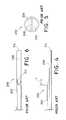
- FIG. 4is a side elevational view of the distal end portion of another prior art hemodialysis catheter assembly
- FIG. 5is a distal end view of the prior art catheter assembly of FIG. 4 ;
- FIG. 6is a top view of the distal end portion of the prior art catheter assembly of FIG. 4 ;
- FIG. 7is a side elevational view of the distal end portion of a catheter according to an embodiment of the present invention.
- FIG. 8is a distal end view of the catheter of FIG. 7 ;
- FIG. 9is a top view of portion of the catheter of FIG. 7 ;
- FIG. 10is a bottom view of the catheter of FIG. 7 ;
- FIG. 11is a transverse sectional view taken along line 11 - 11 of FIG. 7 ;
- FIG. 12is a longitudinal section view taken along line 12 - 12 of FIG. 9 ;
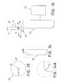
- FIG. 13is a front view of a grinding wheel for use in forming a catheter port according to an embodiment of the present invention.
- FIG. 14is a side view of the grinding wheel of FIG. 13 ;
- FIG. 14Ais an enlarged view of an edge portion of the grinding wheel shown in FIG. 14 ;
- FIG. 15is a view showing an alignment of the grinding wheel with the elongated catheter body prior to cutting a port having a helical profile into the catheter body;
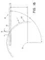
- FIG. 16is a side view of a portion of the grinding wheel illustrating the spatial relationship with the distal end of the catheter during the grinding process
- FIG. 17is a top view of the embodiment shown in FIG. 16 , wherein the catheter material distal to the helical opening has been ground away;
- FIG. 18is an end view of the junction shown in FIG. 16 showing the overlap between the grinding wheel and the distal end of the catheter.
- FIG. 19is an oblique view of FIG. 18 showing the interaction of the radius R 2 of the grinding wheel and the impact on the angle A 2 of the helical opening;
- FIG. 20is a view showing the use of a grinding wheel to cut the proximal port in the prior art catheter of FIG. 1 .
- the present inventionis directed to a catheter for use in the transport of bodily fluids for treatment external of the body, referred to in the medical arts as “extracorporeal” treatment.
- the bodily fluidsare transported from the body through a withdrawal lumen in the catheter, and are thereafter transported to an instrument for extracorporeal treatment.
- the treated fluidsare then returned, or infused, to the body through an infusion lumen in the catheter.
- the catheter described hereinis suitable for multiple uses involving inflow and outflow of bodily fluids.
- the inventionwill be primarily described hereinafter with reference to one of its intended uses, namely as a hemodialysis catheter for use in the extracorporeal treatment of blood.
- the hemodialysis catheterenables blood inflow without disturbance, and blood return without hemolysis.
- the cathetercan be used for other extracorporeal fluid treatments in which a body fluid is withdrawn from the body, subjected to a treatment process, and thereafter returned to the body. Pheresis and hemofiltration are non-limiting examples of such additional procedures.
- proximal and distalwill be used to describe the axial ends of the catheter, as well as the axial ends of various component features.
- proximal endis used in conventional manner to refer to the end of the catheter (or component) that is closest to the operator during use of the assembly.
- distal endis used in conventional manner to refer to the end of the catheter (or component) that is initially inserted into the patient, or that is closest to the patient.
- FIG. 1is a side elevational view of a prior art hemodialysis catheter assembly 100 .
- FIG. 2is an end view taken from the distal end of prior art catheter assembly 100 .
- FIG. 3is a top view of the distal end portion of the catheter assembly 100 .
- Prior art assembly 100includes an elongated generally cylindrical catheter body 102 having a proximal end 103 and a distal end 105 , and having dual lumens 104 , 106 extending therethrough. Lumen 104 is separated from lumen 106 by septum 108 .
- Catheter assembly 100includes a conventional bifurcated fitting at its proximal end, such as manifold 110 .
- Manifold 110may be provided with conventional suture wings 112 if desired.
- Stop mechanisms 114 , 116may be provided at each axial side of suture wings 112 to prevent catheter body 102 from axial movement relative to the suture wings.
- Flexible extension tubes 120 , 122extend in the proximal direction from manifold 110 . Each extension tube is in fluid communication with a separate one of lumens 104 , 106 . Clamps 126 , 128 are provided for selectively closing off fluid flow through the respective extension tubes 120 , 122 .
- Luer lock or other suitable connecting mechanisms 130 , 132are provided for engagement with a treatment instrument 140 , such as a dialyzer, for establishing a flow path of blood to and from the dialyzer. Dialyzer 140 and its ingress and egress openings are shown schematically in FIG. 1 .
- catheter body 102includes a stepped axial surface along the length of catheter body distal end portion 105 .
- Withdrawal port 144communicates with lumen 106 for transporting fluid withdrawn from the body vessel through the catheter assembly to the dialyzer.
- Treated fluidreturns from the dialyzer through lumen 104 , and is returned to the vessel via infusion port 146 .
- withdrawal port 144is proximal to infusion port 146 .
- Ports 144 , 146define a stepped arrangement, wherein port 144 is oriented substantially perpendicular to the vessel wall upon insertion of the apparatus. This orientation is advantageous since it makes it difficult for the wall to collapse over the opening in the port and block the flow of blood.
- FIGS. 4-6Another prior art hemodialysis catheter assembly 200 is shown in FIGS. 4-6 .
- FIG. 4is a side elevational view of the distal end portion of prior art hemodialysis catheter assembly 200 .
- FIG. 5is an end view taken from the distal end of the catheter assembly 200
- FIG. 6is a top view of the portion of the prior art catheter assembly shown in FIG. 4 .
- the proximal portion of assembly 200may be the same or similar to that of prior art assembly 100 , and need not be further shown or described to attain an understanding of the present invention.
- Prior art assembly 200includes an elongated generally cylindrical catheter body 202 , and has dual lumens 204 , 206 extending therethrough. Lumen 204 is separated from lumen 206 by septum 208 . Withdrawal port 212 communicates with lumen 206 for transporting fluid withdrawn from the vessel through the catheter assembly to the dialyzer. Treated fluid returns to the vessel through lumen 204 and infusion port 214 , in the same manner described with reference to the prior art embodiment of FIGS. 1-3 .
- withdrawal port 212 of prior art assembly 200comprises a straight angled cut. This is best visualized at FIG. 4 by reference symbol ⁇ .
- This designhas a more tapered distal portion than the stepped arrangement of assembly 100 , and allows for easier insertion into the vessel.
- the straight angled arrangement defined by straight angled cut ⁇exposes a greater portion of the opening to the vessel wall, thereby increasing the possibility of blockage of the withdrawal port.
- the stepped arrangement of assembly 100FIGS. 1-3 ) minimizes the possibility of blockage.
- the assembly having the stepped arrangementcannot be inserted without the use of a removable sheath, such as the splittable sheaths discussed above.
- FIG. 7is a side elevational view of the distal end portion 13 of a catheter 10 according to an embodiment of the present invention.
- FIG. 8is an end view of the catheter of FIG. 7 .
- FIG. 9is a top view of distal end portion 13 of the catheter of FIG. 7
- FIG. 10is a bottom view of catheter distal end portion 13 .
- the proximal portion of catheter 10is conventional, and need not be further shown and described to attain an understanding of the inventive features of the present invention.
- Catheter 10includes an elongated generally cylindrical catheter body 12 having lumens 14 , 16 extending at least partially therethrough.
- catheter body 12tapers to a tip portion 19 .
- Lumens 14 , 16are separated by a septum 15 .
- FIGS. 11 and 12are respective transverse and longitudinal sectional views taken through catheter body 12 .
- Catheter body 12may be formed from a conventional polymer commonly used in the medical arts for such purposes, such as radiopaque polyurethane. Other conventional materials used for such purposes in the medical arts may be substituted. Non-limiting examples of such materials include silicone, polyurethane and PTFE.
- withdrawal port 18communicates with lumen 16 for transporting fluid withdrawn from the vessel through the catheter assembly to the dialyzer (not shown) for treatment.
- Treated fluidreturns to the vessel through lumen 14 and at least one infusion port.
- two infusion ports 20 , 21are provided for receiving treated fluid and through which the treated fluid passes into the vessel.
- Infusion port 20is positioned at the distal end of tapered tip portion 19 .
- Infusion port 21is provided along the bottom of catheter body 12 .
- infusion port 21is spaced about 1 mm proximal to a transition point 22 between the main catheter body portion and the tapered tip 19 .
- Port 21is provided to prevent the infusion flow rate from being reduced due to the reduction in cross-sectional area of lumen 14 distal of transition point 22 .
- the total cross-sectional area of infusion ports 20 and 21is greater than that of the infusion lumen to insure smooth flow through the infusion lumen, and to inhibit the likelihood of fluid back-up in lumen 14 .
- two infusion portsare illustrated in the embodiment shown herein, those skilled in the art will appreciate that more, or fewer, infusion ports can be provided in the catheter body if desired.
- Insertion of the catheter into the vesselcan be made over a wire guide, e.g., via the well-known Seldinger percutaneous entry technique. Transport of bodily fluid to the dialyzer and return of the treated fluid to the body vessel follows a path substantially similar to that of the prior art embodiments described, and need not be further described.
- the withdrawal port 18 of catheter 10comprises a substantially helically-shaped cut along a portion of the distal outer surface of catheter body 12 .
- the designcombines the beneficial features of the respective stepped and straight angled prior art designs described above, while substantially avoiding the disadvantages of said prior art designs.
- tapered portion 19extends in the proximal direction from infusion port 20 to transition point 22 a distance of about 8 mm at the furthest points, and about 3 mm in the center.
- the helical cutpreferably commences about 30 mm proximal to the transition point 22 , and extends in the proximal direction a distance of about 5 to 15 mm, preferably about 10 mm.
- the infusion lumen 14 and the port opening 20 at the distal tipare not coaxial with the center axis of the catheter body.
- the transitionis generally in the shape of a parabola.
- the helically-shaped cut of the inventive designis advantageous because the opening of the helical cut port remains primarily perpendicular to the vessel wall. This arrangement provides support for the vessel wall, making it more difficult for the wall to collapse over the port opening and block blood flow.
- the tapered distal end portion of the catheteralso constitutes an improvement over the stepped wall design of FIGS. 1-3 , because it allows the assembly to be inserted without the necessity of using a separate introducer sheath.
- the cutsare made with a conventional cutting fixture, such as a grinder or a razor blade, in a similar manner to other cuts that have been made in prior art devices.
- the stepped port in prior art assembly 100may be cut by aligning a grinding wheel 150 in a manner such that the axis of the grinding wheel is positioned parallel to the cylindrical catheter body 102 . This is shown in FIG. 20 .
- the edge of grinding wheel 150has a very small radius, and tubular body 102 is fed along the outer edge of the grinding wheel such that only one lumen is exposed to the grinding wheel.
- the bladeWhen a razor blade or other straightedge is used to cut the proximal (withdrawal) port, the blade can be used to remove all of the material distal to the withdrawal port, or alternatively, only the port material if the catheter is initially ground using the process described above.
- a Jigmay be used to guide the blade and prevent unintended removal of material. In this process, the blade can be held perpendicular to the septum of the catheter body while being rotated, or can be rotated and tilted proximally to create a ramp-like shape.
- a preferred cutting deviceincludes a grinding wheel having dual radii. Having two different radii enables the operator to accurately provide predetermined dimensions on the catheter body for both the length and the longitudinal curvature of the helical port of the catheter.
- FIG. 13illustrates a front, or face, view of a grinding wheel 50 of a type that may be utilized to form the helical port.
- Grinding wheel 50includes a radius R 1 that extends from the radial center 51 of the grinding wheel to the outer circumference 52 of the wheel. Grinding wheel 50 also includes a corner radius R 2 . This radius is shown in FIG. 14 , and in the expanded view of FIG. 14A .
- Radius R 2determines the longitudinal curvature of the helix. Further discussion of R 1 and R 2 and their significance in determining the dimensions of the cut are provided below.
- a conventional power sourcesuch as grinder motor 53 , is provided for rotating grinder wheel 50 .
- an elongated pin 56 having substantially the same general cross-sectional dimension as lumen 14is preferably inserted into lumen 14 . This is shown in FIG. 15 .
- the spacing between the distal and proximal portsis about 3 cm.
- the pinextends into the catheter tube about 1 cm beyond this spacing, or in other words, about 4 cm into the tube from the distal end of the catheter. This length will enable the pin to provide rigidity to the catheter during the helical cutting process.
- pin 56includes an elongated main body 57 and a head 58 extending substantially perpendicular from main body 57 .
- Head 58 of pin 56is engaged in any conventional manner with a conventional pivot assembly 60 , in a manner such that pin 56 is at least partially pivotable about pivot assembly 60 .
- suitable means of rotation of a pin relative to a pivot assemblyand any such means may be substituted for that described and shown herein.
- the tubular catheter body 12is initially aligned with the grinding wheel in the manner shown in FIG. 15 .
- the pivot assembly 60is aligned relative to the grinding wheel 50 such that upon pivoting of the tubular catheter body by the operator around the axis of the pivot assembly, the length of the cut can be controlled.
- FIGS. 16-19illustrate in detail one preferred manner in which the helical cut may be formed in catheter body 12 .
- FIG. 16illustrates a side view of a portion of grinding wheel 50 , illustrating the spatial relationship of the grinding wheel with the distal end 13 of catheter body 12 during the grinding process.
- R 1 , D and A 1represent parameters that may be adjusted to affect the length L of the helical opening cut into the catheter body.
- a 1represents the angle between a vertical plane through the central axis of the grinding wheel and the central axis of the catheter body. An angle of 90° would indicate a catheter body aligned horizontal to the grinding wheel.
- Drepresents the distance from the radial center 51 of the grinding wheel to the axis of the catheter body.
- Dmust be less than R 1 , or the catheter body cannot come into contact with the face of the grinding wheel.
- a 1is less than 90°, D must be reduced to ensure that the entire distal tip of the catheter body is in contact with the face of the grinding wheel (the distal tip will rotate away from the wheel as A 1 is reduced if the catheter axis rotates about the center of the helical port).
- FIG. 17is a top view of the junction of the grinding wheel 50 and catheter distal end 13 shown in FIG. 16 , showing the helical port opening 18 in phantom. As shown in FIG. 17 , the catheter material from lumen 16 distal to the helical opening has been cut away.
- FIG. 18is an end view of the junction of the grinding wheel and catheter body end as shown in FIG. 16 , illustrating an overlap between the grinding wheel and the distal end of catheter body 12 .
- the catheter bodyis positioned such that septum 15 of the catheter body that separates the lumens is nearly flush against the face of the grinding wheel.
- FIG. 19is an oblique view of FIG. 18 , indicating the interaction of the radius R 2 of the grinding wheel and the impact on the angle A 2 of the helical opening.
- R 2controls the angle of the port opening relative to the catheter septum. A steeper opening is generally preferred to avoid blockage by the vein wall.
- R 2will be no larger than the radius of the catheter to keep the opening at 90°.
- a 1represents the angle between the opening of the helical port and catheter septum 15 . Since A 2 is preferably 90°, R 2 is no larger than the radius of the catheter body. If R 2 is larger than this radius, the shape of the helical port will only be a partial radius or arc, and will not be able to follow the radius a full 90°.
- the angle of the openingcan be estimated by lines 28 tangent to the radius, as labeled in FIG. 19 .
- a longer port length (L)is preferred for ease of insertion.
- considerationmust also be given to not having an excessively long port, since a longer port length may be more susceptible to clot formation when the catheter is not in use than a shorter port length.
- a heparin lock of the typethat might normally be used between dialysis sessions to inhibit clotting cannot remain in place within the entire opening. Due to the novel helical port shape, the lock can only exist up to the proximal edge of the helical port. Anything distal to that will not be trapped by vacuum within the catheter, and will enter the bloodstream. In addition, contact with the bloodstream will draw off any heparin solution that is exposed to it.
- a balance between the use of a heparin lock and the ease of insertion of the cathetermust be obtained.
- the port opening described hereinmay also be formed by other methods.
- the pincan be stationary, and the catheter can be ground as it is slid over the pin.
- the pincan rotate in a plane parallel to the face of the grinder, as described in the current embodiment, or alternatively, the pin can rotate in a plane perpendicular to the face of the wheel.
- This arrangementmay be advantageous because it would minimize the contact duration between the catheter and the grinder. The longer that the catheter stays in contact with the grinder, the more heat is generated due to friction. This could result in material deformation and/or excess material removal.
- the majority of the distal tipcan be removed in a separate step, with only the details of the helical port being addressed with the process described herein.
- the helical profileneed not necessarily extend the entire length of the port, and beneficial results may be obtained when only a portion of the port includes a generally helically-shaped profile.
Landscapes
- Health & Medical Sciences (AREA)
- Life Sciences & Earth Sciences (AREA)
- Biophysics (AREA)
- Pulmonology (AREA)
- Engineering & Computer Science (AREA)
- Anesthesiology (AREA)
- Biomedical Technology (AREA)
- Heart & Thoracic Surgery (AREA)
- Hematology (AREA)
- Animal Behavior & Ethology (AREA)
- General Health & Medical Sciences (AREA)
- Public Health (AREA)
- Veterinary Medicine (AREA)
- External Artificial Organs (AREA)
Abstract
Description
Claims (15)
Priority Applications (1)
| Application Number | Priority Date | Filing Date | Title |
|---|---|---|---|
| US11/877,057US8545434B2 (en) | 2006-10-26 | 2007-10-23 | Catheter port configuration |
Applications Claiming Priority (2)
| Application Number | Priority Date | Filing Date | Title |
|---|---|---|---|
| US85451506P | 2006-10-26 | 2006-10-26 | |
| US11/877,057US8545434B2 (en) | 2006-10-26 | 2007-10-23 | Catheter port configuration |
Publications (2)
| Publication Number | Publication Date |
|---|---|
| US20080103480A1 US20080103480A1 (en) | 2008-05-01 |
| US8545434B2true US8545434B2 (en) | 2013-10-01 |
Family
ID=39325328
Family Applications (1)
| Application Number | Title | Priority Date | Filing Date |
|---|---|---|---|
| US11/877,057Active2028-11-19US8545434B2 (en) | 2006-10-26 | 2007-10-23 | Catheter port configuration |
Country Status (3)
| Country | Link |
|---|---|
| US (1) | US8545434B2 (en) |
| EP (1) | EP2077884A2 (en) |
| WO (1) | WO2008051959A2 (en) |
Cited By (3)
| Publication number | Priority date | Publication date | Assignee | Title |
|---|---|---|---|---|
| US20160242802A1 (en)* | 2010-03-03 | 2016-08-25 | Seiko Epson Corporation | Fluid injection device |
| US20210275139A1 (en)* | 2018-02-28 | 2021-09-09 | Gyrus ACMI, Inc. d/ba Olympus Surgical Technologies America | Orientation pins for device using radial ultrasound |
| US11596745B2 (en)* | 2016-10-06 | 2023-03-07 | Kitazato Corporation | Living cell transplanting tool |
Families Citing this family (9)
| Publication number | Priority date | Publication date | Assignee | Title |
|---|---|---|---|---|
| EP3628247B1 (en) | 2012-02-07 | 2022-08-10 | Intervene, Inc. | System for endoluminal valve creation |
| WO2014110460A1 (en) | 2013-01-10 | 2014-07-17 | Intervene, Inc. | Systems and methods for endoluminal valve creation |
| WO2015048565A2 (en)* | 2013-09-27 | 2015-04-02 | Intervene, Inc. | Visualization devices, systems, and methods for informing intravascular procedures on blood vessel valves |
| WO2015148581A1 (en) | 2014-03-24 | 2015-10-01 | Intervene, Inc. | Devices, systems, and methods for controlled hydrodissection of vessel walls |
| WO2016100574A2 (en) | 2014-12-16 | 2016-06-23 | Intervene, Inc. | Intravascular devices, systems, and methods for the controlled dissection of body lumens |
| US10646247B2 (en) | 2016-04-01 | 2020-05-12 | Intervene, Inc. | Intraluminal tissue modifying systems and associated devices and methods |
| JP7246328B2 (en) | 2017-06-27 | 2023-03-27 | ミシガン クリティカル ケア コンサルタンツ インク | catheter for extracorporeal circulation |
| US11771501B2 (en) | 2020-06-23 | 2023-10-03 | Intervene, Inc. | Endovascular valve formation system with imaging capability |
| US20240075247A1 (en)* | 2020-12-31 | 2024-03-07 | Nuwellis, Inc. | Dual lumen catheter |
Citations (91)
| Publication number | Priority date | Publication date | Assignee | Title |
|---|---|---|---|---|
| US3938530A (en) | 1974-11-15 | 1976-02-17 | Santomieri Louis | Catheter |
| US3946741A (en) | 1974-12-09 | 1976-03-30 | Adair Edwin Lloyd | Urethral catheter and body drainage device |
| US4129129A (en) | 1977-03-18 | 1978-12-12 | Sarns, Inc. | Venous return catheter and a method of using the same |
| US4134402A (en) | 1976-02-11 | 1979-01-16 | Mahurkar Sakharam D | Double lumen hemodialysis catheter |
| US4154242A (en) | 1977-06-17 | 1979-05-15 | Zafmedico Corp. | Bladder catheter |
| US4493696A (en) | 1979-12-28 | 1985-01-15 | Allentyne Limited | Hemodialysis cannular for subclavian insertion |
| USRE31855E (en) | 1978-12-01 | 1985-03-26 | Cook, Inc. | Tear apart cannula |
| US4568329A (en) | 1982-03-08 | 1986-02-04 | Mahurkar Sakharam D | Double lumen catheter |
| US4581025A (en) | 1983-11-14 | 1986-04-08 | Cook Incorporated | Sheath |
| US4583968A (en) | 1983-10-03 | 1986-04-22 | Mahurkar Sakharam D | Smooth bore double lumen catheter |
| US4643711A (en) | 1984-05-25 | 1987-02-17 | Cook, Inc. | Two lumen hemodialysis catheter |
| US4655745A (en) | 1985-07-29 | 1987-04-07 | Corbett Joseph E | Ventricular catheter |
| US4680029A (en) | 1984-02-23 | 1987-07-14 | Sherwood Medical Company | Vena caval catheter |
| US4692141A (en)* | 1982-03-08 | 1987-09-08 | Mahurkar Sakharam D | Double lumen catheter |
| US4733669A (en) | 1985-05-24 | 1988-03-29 | Cardiometrics, Inc. | Blood flow measurement catheter |
| US4772268A (en) | 1984-05-25 | 1988-09-20 | Cook Incorporated | Two lumen hemodialysis catheter |
| EP0301854A2 (en) | 1987-07-29 | 1989-02-01 | LAUB, Glenn W. | Percutaneous venous cannula for cardiopulmonary bypass |
| US4878893A (en) | 1988-04-28 | 1989-11-07 | Thomas J. Fogarty | Angioscope with flush solution deflector shield |
| US4904238A (en) | 1987-12-21 | 1990-02-27 | Alcon Laboratories, Inc. | Irrigation/aspiration handpiece |
| US4936826A (en) | 1988-10-24 | 1990-06-26 | Amarasinghe Disamodha C | Vena cava window |
| US4973301A (en) | 1989-07-11 | 1990-11-27 | Israel Nissenkorn | Catheter and method of using same |
| US4995865A (en) | 1989-06-09 | 1991-02-26 | Worldwide Medical Plastics Inc. | Multi-lumen catheters |
| US4995868A (en) | 1988-10-12 | 1991-02-26 | Bard Limited | Catheter |
| US5106368A (en) | 1990-04-20 | 1992-04-21 | Cook Incorporated | Collapsible lumen catheter for extracorporeal treatment |
| US5156597A (en) | 1989-12-30 | 1992-10-20 | B. Braun Melsungen Ag | Transcutaneous implantation catheter |
| US5193533A (en) | 1990-07-09 | 1993-03-16 | Brigham And Women's Hospital | High-pressure jet ventilation catheter |
| US5221256A (en) | 1992-02-10 | 1993-06-22 | Mahurkar Sakharam D | Multiple-lumen catheter |
| US5250034A (en) | 1990-09-17 | 1993-10-05 | E-Z-Em, Inc. | Pressure responsive valve catheter |
| US5275610A (en) | 1991-05-13 | 1994-01-04 | Cook Incorporated | Surgical retractors and method of use |
| US5352198A (en) | 1993-11-24 | 1994-10-04 | Uresil Corporation | Locking catheter system |
| US5360397A (en) | 1993-07-02 | 1994-11-01 | Corvita Corporation | Hemodiaylsis catheter and catheter assembly |
| US5364344A (en) | 1993-10-22 | 1994-11-15 | The Kendall Company | Dual lumen catheter |
| US5403291A (en) | 1993-08-02 | 1995-04-04 | Quinton Instrument Company | Catheter with elongated side holes |
| US5409460A (en) | 1993-04-15 | 1995-04-25 | The Beta Group Inc. | Intra-luminal expander assembly |
| US5443449A (en) | 1991-03-01 | 1995-08-22 | Applied Medical Resources Corporation | Cholangiography catheter |
| US5486159A (en) | 1993-10-01 | 1996-01-23 | Mahurkar; Sakharam D. | Multiple-lumen catheter |
| US5509900A (en) | 1992-03-02 | 1996-04-23 | Kirkman; Thomas R. | Apparatus and method for retaining a catheter in a blood vessel in a fixed position |
| US5509897A (en) | 1990-01-08 | 1996-04-23 | The Curators Of The University Of Missouri | Multiple lumen catheter for hemodialysis |
| US5514112A (en) | 1992-10-02 | 1996-05-07 | Boston Scientific Corporation | Drainage catheter and method of use |
| US5518498A (en) | 1992-10-09 | 1996-05-21 | Angiomed Ag | Stent set |
| US5522400A (en) | 1994-11-23 | 1996-06-04 | Uresil Corp | Locking catheter system |
| US5571093A (en) | 1994-09-21 | 1996-11-05 | Cruz; Cosme | Multiple-lumen catheter |
| US5681280A (en) | 1995-05-02 | 1997-10-28 | Heart Rhythm Technologies, Inc. | Catheter control system |
| US5702365A (en) | 1992-09-08 | 1997-12-30 | King; Toby St. John | Daul-lumen catheter |
| US5713853A (en) | 1995-06-07 | 1998-02-03 | Interventional Innovations Corporation | Methods for treating thrombosis |
| US5749826A (en) | 1996-11-06 | 1998-05-12 | Faulkner; James W. | Urinary incontinence control device |
| US5817067A (en) | 1995-12-01 | 1998-10-06 | Tsukada Medical Research Co., Ltd. | Cap for medical appliance to be retained in human body |
| US5857464A (en) | 1995-06-07 | 1999-01-12 | Desai; Jawahar M. | Catheter for media injection |
| US5885258A (en) | 1996-02-23 | 1999-03-23 | Memory Medical Systems, Inc. | Medical instrument with slotted memory metal tube |
| US5888196A (en) | 1990-03-02 | 1999-03-30 | General Surgical Innovations, Inc. | Mechanically expandable arthroscopic retractors |
| US5957900A (en) | 1996-07-10 | 1999-09-28 | Asahi Kogaku Kogyo Kabushiki Kaisha | Treatment accessory for endoscope |
| US6001079A (en) | 1995-09-05 | 1999-12-14 | Pourchez; Thierry | Multilumen catheter, particularly for hemodialysis |
| US6033397A (en) | 1996-03-05 | 2000-03-07 | Vnus Medical Technologies, Inc. | Method and apparatus for treating esophageal varices |
| US6052612A (en) | 1995-06-07 | 2000-04-18 | Desai; Jawahar M. | Catheter for media injection |
| US6177049B1 (en) | 1998-06-10 | 2001-01-23 | Dsu Medical Corporation | Reversing flow blood processing system |
| US6179813B1 (en)* | 1998-04-24 | 2001-01-30 | Scimed Life Systems, Inc. | Vascular infusion device |
| WO2001019425A1 (en) | 1999-09-17 | 2001-03-22 | Cook Incorporated | Medical device including expandable balloon |
| US6238412B1 (en) | 1997-11-12 | 2001-05-29 | William Dubrul | Biological passageway occlusion removal |
| US6270490B1 (en) | 1998-09-08 | 2001-08-07 | Embol-X, Inc. | Venous drainage catheter and method of use |
| US20010018576A1 (en) | 1999-11-24 | 2001-08-30 | Radius International Limited Partnership. | Blood vessel catheter |
| US6283940B1 (en) | 1997-08-29 | 2001-09-04 | S. Grant Mulholland | Catheter |
| US6293958B1 (en) | 1998-07-27 | 2001-09-25 | Acist Medical Systems, Inc. | Catheter having flow diffusing tip |
| US6336933B1 (en) | 1998-03-13 | 2002-01-08 | Juan C. Parodi | Endovascular device for application of prosthesis with sutures |
| US20020026156A1 (en) | 2000-08-30 | 2002-02-28 | Radius International Limited Partnership | Hemodialysis catheter |
| US20020072768A1 (en) | 2000-12-07 | 2002-06-13 | Ginn Richard S. | Apparatus and methods for providing tactile feedback while delivering a closure device |
| US6409700B1 (en) | 1999-03-22 | 2002-06-25 | Cfd Research Corporation | Double lumen catheter |
| WO2002064202A2 (en) | 2001-01-09 | 2002-08-22 | Rex Medical, L.P. | Dialysis catheter |
| US6454775B1 (en) | 1999-12-06 | 2002-09-24 | Bacchus Vascular Inc. | Systems and methods for clot disruption and retrieval |
| US20020143292A1 (en) | 2001-04-02 | 2002-10-03 | Flinchbaugh David E. | Conformable balloonless catheter |
| US6475207B1 (en) | 1999-01-15 | 2002-11-05 | Maginot Catheter Technologies, Inc. | Retractable catheter systems and associated methods |
| US6482169B1 (en) | 2000-06-08 | 2002-11-19 | William G. Kuhle | Double-lumen catheter |
| US20020177822A1 (en) | 2001-05-24 | 2002-11-28 | St. Cyr John A. | Dual lumen adjustable length cannulae for liquid perfusion or lavage |
| US6517529B1 (en) | 1999-11-24 | 2003-02-11 | Radius International Limited Partnership | Hemodialysis catheter |
| US20030032918A1 (en) | 2000-08-30 | 2003-02-13 | Quinn David G. | Catheter |
| US6527737B2 (en) | 2000-01-24 | 2003-03-04 | Tatsuo Kaneshige | Indwelling urethra catheter |
| US6547761B2 (en) | 2000-01-07 | 2003-04-15 | Scimed Life Systems, Inc. | Drainage catheter |
| US6558350B1 (en) | 2000-06-20 | 2003-05-06 | Applied Medical Resources Corp. | Drainage catheter |
| US20030093029A1 (en)* | 2001-01-09 | 2003-05-15 | Rex Medical | Dialysis catheter |
| US6569150B2 (en) | 2000-04-11 | 2003-05-27 | Scimed Life Systems, Inc. | Reinforced retention structures |
| US6579302B2 (en) | 2001-03-06 | 2003-06-17 | Cordis Corporation | Total occlusion guidewire device |
| US6758836B2 (en) | 2002-02-07 | 2004-07-06 | C. R. Bard, Inc. | Split tip dialysis catheter |
| US6767339B2 (en) | 1997-12-12 | 2004-07-27 | Wilson-Cook Medical, Inc. | Body canal intrusion instrumentation having bidirectional coefficient of surface friction with body tissue |
| US20050033264A1 (en)* | 2003-08-04 | 2005-02-10 | Peter Redinger | Catheter device |
| WO2005049125A1 (en) | 2003-11-17 | 2005-06-02 | Cook Critical Care Incorporated | Catheter with centering wire |
| US20050177094A1 (en)* | 2002-06-27 | 2005-08-11 | Junichi Igarashi | Multi lumen catheter |
| US6966886B2 (en) | 2002-11-20 | 2005-11-22 | Angiodynamics, Inc. | Blood treatment catheter assembly |
| US20050261663A1 (en) | 2004-03-03 | 2005-11-24 | Patterson Ryan C | Loop-tip catheter |
| WO2006002192A2 (en) | 2004-06-21 | 2006-01-05 | Sherwood Services Ag | Triple lumen catheter with occlusion resistant tip |
| US20060253063A1 (en) | 2005-05-09 | 2006-11-09 | Medical Components, Inc. | Security tip for vascular catheter and method of using same |
| US20070016124A1 (en) | 2005-06-23 | 2007-01-18 | Mcgraw J K | Hemodialysis catheter apparatus |
| USD581529S1 (en)* | 2007-10-12 | 2008-11-25 | C. R. Bard, Inc. | Catheter tip |
Family Cites Families (1)
| Publication number | Priority date | Publication date | Assignee | Title |
|---|---|---|---|---|
| US6011079A (en)* | 1997-10-09 | 2000-01-04 | Isp Investments Inc. | Release coating compositions comprising an acrylate-functional silicone resin and a vinylether |
- 2007
- 2007-10-23USUS11/877,057patent/US8545434B2/enactiveActive
- 2007-10-23EPEP07854328Apatent/EP2077884A2/ennot_activeWithdrawn
- 2007-10-23WOPCT/US2007/082203patent/WO2008051959A2/enactiveApplication Filing
Patent Citations (102)
| Publication number | Priority date | Publication date | Assignee | Title |
|---|---|---|---|---|
| US3938530A (en) | 1974-11-15 | 1976-02-17 | Santomieri Louis | Catheter |
| US3946741A (en) | 1974-12-09 | 1976-03-30 | Adair Edwin Lloyd | Urethral catheter and body drainage device |
| US4134402A (en) | 1976-02-11 | 1979-01-16 | Mahurkar Sakharam D | Double lumen hemodialysis catheter |
| US4134402B1 (en) | 1976-02-11 | 1989-07-25 | ||
| US4129129A (en) | 1977-03-18 | 1978-12-12 | Sarns, Inc. | Venous return catheter and a method of using the same |
| US4154242A (en) | 1977-06-17 | 1979-05-15 | Zafmedico Corp. | Bladder catheter |
| USRE31855E (en) | 1978-12-01 | 1985-03-26 | Cook, Inc. | Tear apart cannula |
| USRE31855F1 (en) | 1978-12-01 | 1986-08-19 | Tear apart cannula | |
| US4493696A (en) | 1979-12-28 | 1985-01-15 | Allentyne Limited | Hemodialysis cannular for subclavian insertion |
| US4568329A (en) | 1982-03-08 | 1986-02-04 | Mahurkar Sakharam D | Double lumen catheter |
| US4692141A (en)* | 1982-03-08 | 1987-09-08 | Mahurkar Sakharam D | Double lumen catheter |
| US4583968A (en) | 1983-10-03 | 1986-04-22 | Mahurkar Sakharam D | Smooth bore double lumen catheter |
| US4581025A (en) | 1983-11-14 | 1986-04-08 | Cook Incorporated | Sheath |
| US4680029A (en) | 1984-02-23 | 1987-07-14 | Sherwood Medical Company | Vena caval catheter |
| US4643711A (en) | 1984-05-25 | 1987-02-17 | Cook, Inc. | Two lumen hemodialysis catheter |
| US4772268A (en) | 1984-05-25 | 1988-09-20 | Cook Incorporated | Two lumen hemodialysis catheter |
| US4733669A (en) | 1985-05-24 | 1988-03-29 | Cardiometrics, Inc. | Blood flow measurement catheter |
| US4655745A (en) | 1985-07-29 | 1987-04-07 | Corbett Joseph E | Ventricular catheter |
| US4808163A (en) | 1987-07-29 | 1989-02-28 | Laub Glenn W | Percutaneous venous cannula for cardiopulmonary bypass |
| EP0301854A2 (en) | 1987-07-29 | 1989-02-01 | LAUB, Glenn W. | Percutaneous venous cannula for cardiopulmonary bypass |
| US4904238A (en) | 1987-12-21 | 1990-02-27 | Alcon Laboratories, Inc. | Irrigation/aspiration handpiece |
| US4878893A (en) | 1988-04-28 | 1989-11-07 | Thomas J. Fogarty | Angioscope with flush solution deflector shield |
| US4995868A (en) | 1988-10-12 | 1991-02-26 | Bard Limited | Catheter |
| US4936826A (en) | 1988-10-24 | 1990-06-26 | Amarasinghe Disamodha C | Vena cava window |
| US4995865A (en) | 1989-06-09 | 1991-02-26 | Worldwide Medical Plastics Inc. | Multi-lumen catheters |
| US4973301A (en) | 1989-07-11 | 1990-11-27 | Israel Nissenkorn | Catheter and method of using same |
| US5156597A (en) | 1989-12-30 | 1992-10-20 | B. Braun Melsungen Ag | Transcutaneous implantation catheter |
| US5509897A (en) | 1990-01-08 | 1996-04-23 | The Curators Of The University Of Missouri | Multiple lumen catheter for hemodialysis |
| US5888196A (en) | 1990-03-02 | 1999-03-30 | General Surgical Innovations, Inc. | Mechanically expandable arthroscopic retractors |
| US5106368A (en) | 1990-04-20 | 1992-04-21 | Cook Incorporated | Collapsible lumen catheter for extracorporeal treatment |
| US5193533A (en) | 1990-07-09 | 1993-03-16 | Brigham And Women's Hospital | High-pressure jet ventilation catheter |
| US5250034A (en) | 1990-09-17 | 1993-10-05 | E-Z-Em, Inc. | Pressure responsive valve catheter |
| US5443449A (en) | 1991-03-01 | 1995-08-22 | Applied Medical Resources Corporation | Cholangiography catheter |
| US5275610A (en) | 1991-05-13 | 1994-01-04 | Cook Incorporated | Surgical retractors and method of use |
| US5221256A (en) | 1992-02-10 | 1993-06-22 | Mahurkar Sakharam D | Multiple-lumen catheter |
| US6071263A (en) | 1992-03-02 | 2000-06-06 | Kirkman; Thomas R. | Apparatus and method for retaining a catheter in a blood vessel in a fixed position |
| US6558349B1 (en) | 1992-03-02 | 2003-05-06 | Thomas R. Kirkman | Apparatus and method for retaining a catheter in a blood vessel in a fixed position |
| US5509900A (en) | 1992-03-02 | 1996-04-23 | Kirkman; Thomas R. | Apparatus and method for retaining a catheter in a blood vessel in a fixed position |
| US5702365A (en) | 1992-09-08 | 1997-12-30 | King; Toby St. John | Daul-lumen catheter |
| US5514112A (en) | 1992-10-02 | 1996-05-07 | Boston Scientific Corporation | Drainage catheter and method of use |
| US5518498A (en) | 1992-10-09 | 1996-05-21 | Angiomed Ag | Stent set |
| US5409460A (en) | 1993-04-15 | 1995-04-25 | The Beta Group Inc. | Intra-luminal expander assembly |
| US5360397A (en) | 1993-07-02 | 1994-11-01 | Corvita Corporation | Hemodiaylsis catheter and catheter assembly |
| US5403291A (en) | 1993-08-02 | 1995-04-04 | Quinton Instrument Company | Catheter with elongated side holes |
| US5489278A (en) | 1993-08-02 | 1996-02-06 | Quinton Instrument Company | Catheter with elongated side openings |
| US5486159A (en) | 1993-10-01 | 1996-01-23 | Mahurkar; Sakharam D. | Multiple-lumen catheter |
| US5364344A (en) | 1993-10-22 | 1994-11-15 | The Kendall Company | Dual lumen catheter |
| US5352198A (en) | 1993-11-24 | 1994-10-04 | Uresil Corporation | Locking catheter system |
| US5571093A (en) | 1994-09-21 | 1996-11-05 | Cruz; Cosme | Multiple-lumen catheter |
| US5522400A (en) | 1994-11-23 | 1996-06-04 | Uresil Corp | Locking catheter system |
| US5681280A (en) | 1995-05-02 | 1997-10-28 | Heart Rhythm Technologies, Inc. | Catheter control system |
| US5713853A (en) | 1995-06-07 | 1998-02-03 | Interventional Innovations Corporation | Methods for treating thrombosis |
| US5857464A (en) | 1995-06-07 | 1999-01-12 | Desai; Jawahar M. | Catheter for media injection |
| US6052612A (en) | 1995-06-07 | 2000-04-18 | Desai; Jawahar M. | Catheter for media injection |
| US6001079A (en) | 1995-09-05 | 1999-12-14 | Pourchez; Thierry | Multilumen catheter, particularly for hemodialysis |
| US5817067A (en) | 1995-12-01 | 1998-10-06 | Tsukada Medical Research Co., Ltd. | Cap for medical appliance to be retained in human body |
| US5885258A (en) | 1996-02-23 | 1999-03-23 | Memory Medical Systems, Inc. | Medical instrument with slotted memory metal tube |
| US6033397A (en) | 1996-03-05 | 2000-03-07 | Vnus Medical Technologies, Inc. | Method and apparatus for treating esophageal varices |
| US5957900A (en) | 1996-07-10 | 1999-09-28 | Asahi Kogaku Kogyo Kabushiki Kaisha | Treatment accessory for endoscope |
| US5749826A (en) | 1996-11-06 | 1998-05-12 | Faulkner; James W. | Urinary incontinence control device |
| US6283940B1 (en) | 1997-08-29 | 2001-09-04 | S. Grant Mulholland | Catheter |
| US6238412B1 (en) | 1997-11-12 | 2001-05-29 | William Dubrul | Biological passageway occlusion removal |
| US20010011182A1 (en) | 1997-11-12 | 2001-08-02 | William Dubrul | Biological passageway occlusion removal |
| US6767339B2 (en) | 1997-12-12 | 2004-07-27 | Wilson-Cook Medical, Inc. | Body canal intrusion instrumentation having bidirectional coefficient of surface friction with body tissue |
| US6336933B1 (en) | 1998-03-13 | 2002-01-08 | Juan C. Parodi | Endovascular device for application of prosthesis with sutures |
| US6179813B1 (en)* | 1998-04-24 | 2001-01-30 | Scimed Life Systems, Inc. | Vascular infusion device |
| US6177049B1 (en) | 1998-06-10 | 2001-01-23 | Dsu Medical Corporation | Reversing flow blood processing system |
| US6293958B1 (en) | 1998-07-27 | 2001-09-25 | Acist Medical Systems, Inc. | Catheter having flow diffusing tip |
| US6270490B1 (en) | 1998-09-08 | 2001-08-07 | Embol-X, Inc. | Venous drainage catheter and method of use |
| US6475207B1 (en) | 1999-01-15 | 2002-11-05 | Maginot Catheter Technologies, Inc. | Retractable catheter systems and associated methods |
| US6409700B1 (en) | 1999-03-22 | 2002-06-25 | Cfd Research Corporation | Double lumen catheter |
| WO2001019425A1 (en) | 1999-09-17 | 2001-03-22 | Cook Incorporated | Medical device including expandable balloon |
| US20010018576A1 (en) | 1999-11-24 | 2001-08-30 | Radius International Limited Partnership. | Blood vessel catheter |
| US6517529B1 (en) | 1999-11-24 | 2003-02-11 | Radius International Limited Partnership | Hemodialysis catheter |
| US6454775B1 (en) | 1999-12-06 | 2002-09-24 | Bacchus Vascular Inc. | Systems and methods for clot disruption and retrieval |
| US6547761B2 (en) | 2000-01-07 | 2003-04-15 | Scimed Life Systems, Inc. | Drainage catheter |
| US6527737B2 (en) | 2000-01-24 | 2003-03-04 | Tatsuo Kaneshige | Indwelling urethra catheter |
| US6569150B2 (en) | 2000-04-11 | 2003-05-27 | Scimed Life Systems, Inc. | Reinforced retention structures |
| US6482169B1 (en) | 2000-06-08 | 2002-11-19 | William G. Kuhle | Double-lumen catheter |
| US6558350B1 (en) | 2000-06-20 | 2003-05-06 | Applied Medical Resources Corp. | Drainage catheter |
| US20030032918A1 (en) | 2000-08-30 | 2003-02-13 | Quinn David G. | Catheter |
| US6461321B1 (en) | 2000-08-30 | 2002-10-08 | Radius International Limited Partnership | Hemodialysis catheter |
| US20020026156A1 (en) | 2000-08-30 | 2002-02-28 | Radius International Limited Partnership | Hemodialysis catheter |
| US20020072768A1 (en) | 2000-12-07 | 2002-06-13 | Ginn Richard S. | Apparatus and methods for providing tactile feedback while delivering a closure device |
| WO2002064202A3 (en) | 2001-01-09 | 2003-11-27 | Rex Medical Lp | Dialysis catheter |
| WO2002064202A2 (en) | 2001-01-09 | 2002-08-22 | Rex Medical, L.P. | Dialysis catheter |
| US20030093029A1 (en)* | 2001-01-09 | 2003-05-15 | Rex Medical | Dialysis catheter |
| US6579302B2 (en) | 2001-03-06 | 2003-06-17 | Cordis Corporation | Total occlusion guidewire device |
| US20030139763A1 (en) | 2001-03-06 | 2003-07-24 | Duerig Thomas W. | Total occlusion guidewire device |
| US20020143292A1 (en) | 2001-04-02 | 2002-10-03 | Flinchbaugh David E. | Conformable balloonless catheter |
| US20020177822A1 (en) | 2001-05-24 | 2002-11-28 | St. Cyr John A. | Dual lumen adjustable length cannulae for liquid perfusion or lavage |
| US6758836B2 (en) | 2002-02-07 | 2004-07-06 | C. R. Bard, Inc. | Split tip dialysis catheter |
| US20050177094A1 (en)* | 2002-06-27 | 2005-08-11 | Junichi Igarashi | Multi lumen catheter |
| US6966886B2 (en) | 2002-11-20 | 2005-11-22 | Angiodynamics, Inc. | Blood treatment catheter assembly |
| US20050033264A1 (en)* | 2003-08-04 | 2005-02-10 | Peter Redinger | Catheter device |
| WO2005049125A1 (en) | 2003-11-17 | 2005-06-02 | Cook Critical Care Incorporated | Catheter with centering wire |
| US20050148929A1 (en) | 2003-11-17 | 2005-07-07 | Bruce Gingles | Catheter with centering wire |
| US20050261663A1 (en) | 2004-03-03 | 2005-11-24 | Patterson Ryan C | Loop-tip catheter |
| WO2006002192A2 (en) | 2004-06-21 | 2006-01-05 | Sherwood Services Ag | Triple lumen catheter with occlusion resistant tip |
| US20060253063A1 (en) | 2005-05-09 | 2006-11-09 | Medical Components, Inc. | Security tip for vascular catheter and method of using same |
| US20070016124A1 (en) | 2005-06-23 | 2007-01-18 | Mcgraw J K | Hemodialysis catheter apparatus |
| USD581529S1 (en)* | 2007-10-12 | 2008-11-25 | C. R. Bard, Inc. | Catheter tip |
Non-Patent Citations (1)
| Title |
|---|
| International Search Report and Written Opinion dated Jun. 4, 2008, from International Application No. PCT/US2007/082203. |
Cited By (6)
| Publication number | Priority date | Publication date | Assignee | Title |
|---|---|---|---|---|
| US20160242802A1 (en)* | 2010-03-03 | 2016-08-25 | Seiko Epson Corporation | Fluid injection device |
| US11596745B2 (en)* | 2016-10-06 | 2023-03-07 | Kitazato Corporation | Living cell transplanting tool |
| US20210275139A1 (en)* | 2018-02-28 | 2021-09-09 | Gyrus ACMI, Inc. d/ba Olympus Surgical Technologies America | Orientation pins for device using radial ultrasound |
| US11737730B2 (en)* | 2018-02-28 | 2023-08-29 | Olympus Medical Systems Corporation | Orientation pins for device using radial ultrasound |
| US20230338007A1 (en)* | 2018-02-28 | 2023-10-26 | Olympus Medical Systems Corporation | Orientation pins for device using radial ultrasound |
| US12426853B2 (en)* | 2018-02-28 | 2025-09-30 | Olympus Medical Systems Corporation | Orientation pins for device using radial ultrasound |
Also Published As
| Publication number | Publication date |
|---|---|
| WO2008051959A2 (en) | 2008-05-02 |
| WO2008051959A3 (en) | 2008-08-07 |
| EP2077884A2 (en) | 2009-07-15 |
| US20080103480A1 (en) | 2008-05-01 |
Similar Documents
| Publication | Publication Date | Title |
|---|---|---|
| US8545434B2 (en) | Catheter port configuration | |
| US9248253B2 (en) | Winged catheter assembly | |
| EP2183012B1 (en) | Multi-lumen catheter assembly | |
| US8496607B2 (en) | Multi-lumen catheter | |
| US10220184B2 (en) | Multi-lumen catheter | |
| US7753868B2 (en) | Multi-lumen catheter | |
| US8517978B2 (en) | Multi-lumen catheter | |
| US7922687B2 (en) | Catheter with centering wire | |
| EP1898990B1 (en) | Security tip for vascular catheter | |
| CN104379208B (en) | multi-lumen catheter | |
| US20100145285A1 (en) | Multi-lumen catheter configuration | |
| US20200030574A1 (en) | Multilumen Curved Split-tip Catheter | |
| EP1556112B1 (en) | Dialysis catheter |
Legal Events
| Date | Code | Title | Description |
|---|---|---|---|
| AS | Assignment | Owner name:COOK CRITICAL CARE INCORPORATED, INDIANA Free format text:ASSIGNMENT OF ASSIGNORS INTEREST;ASSIGNORS:BOSEL, CHRISTOPHER D.;LYONS, DREW P.;REEL/FRAME:020006/0232 Effective date:20071016 | |
| AS | Assignment | Owner name:COOK MEDICAL TECHNOLOGIES LLC, INDIANA Free format text:ASSIGNMENT OF ASSIGNORS INTEREST;ASSIGNOR:COOK INCORPORATED, D/B/A COOK CRITICAL CARE;REEL/FRAME:027061/0050 Effective date:20110101 | |
| STCF | Information on status: patent grant | Free format text:PATENTED CASE | |
| CC | Certificate of correction | ||
| FPAY | Fee payment | Year of fee payment:4 | |
| MAFP | Maintenance fee payment | Free format text:PAYMENT OF MAINTENANCE FEE, 8TH YEAR, LARGE ENTITY (ORIGINAL EVENT CODE: M1552); ENTITY STATUS OF PATENT OWNER: LARGE ENTITY Year of fee payment:8 | |
| AS | Assignment | Owner name:WILMINGTON TRUST, NATIONAL ASSOCIATION, AS COLLATERAL AGENT, DELAWARE Free format text:SECURITY INTEREST;ASSIGNOR:COOK MEDICAL TECHNOLOGIES LLC;REEL/FRAME:066700/0277 Effective date:20240227 | |
| MAFP | Maintenance fee payment | Free format text:PAYMENT OF MAINTENANCE FEE, 12TH YEAR, LARGE ENTITY (ORIGINAL EVENT CODE: M1553); ENTITY STATUS OF PATENT OWNER: LARGE ENTITY Year of fee payment:12 |