US8545418B2 - Systems and methods for ablation of occlusions within blood vessels - Google Patents
Systems and methods for ablation of occlusions within blood vesselsDownload PDFInfo
- Publication number
- US8545418B2 US8545418B2US12/356,446US35644609AUS8545418B2US 8545418 B2US8545418 B2US 8545418B2US 35644609 AUS35644609 AUS 35644609AUS 8545418 B2US8545418 B2US 8545418B2
- Authority
- US
- United States
- Prior art keywords
- wire
- distal end
- proximal end
- distal
- blood vessel
- Prior art date
- Legal status (The legal status is an assumption and is not a legal conclusion. Google has not performed a legal analysis and makes no representation as to the accuracy of the status listed.)
- Active, expires
Links
Images


Classifications
- A—HUMAN NECESSITIES
- A61—MEDICAL OR VETERINARY SCIENCE; HYGIENE
- A61M—DEVICES FOR INTRODUCING MEDIA INTO, OR ONTO, THE BODY; DEVICES FOR TRANSDUCING BODY MEDIA OR FOR TAKING MEDIA FROM THE BODY; DEVICES FOR PRODUCING OR ENDING SLEEP OR STUPOR
- A61M25/00—Catheters; Hollow probes
- A61M25/01—Introducing, guiding, advancing, emplacing or holding catheters
- A61M25/09—Guide wires
- A—HUMAN NECESSITIES
- A61—MEDICAL OR VETERINARY SCIENCE; HYGIENE
- A61B—DIAGNOSIS; SURGERY; IDENTIFICATION
- A61B18/00—Surgical instruments, devices or methods for transferring non-mechanical forms of energy to or from the body
- A61B18/04—Surgical instruments, devices or methods for transferring non-mechanical forms of energy to or from the body by heating
- A61B18/12—Surgical instruments, devices or methods for transferring non-mechanical forms of energy to or from the body by heating by passing a current through the tissue to be heated, e.g. high-frequency current
- A61B18/14—Probes or electrodes therefor
- A61B18/1492—Probes or electrodes therefor having a flexible, catheter-like structure, e.g. for heart ablation
- A—HUMAN NECESSITIES
- A61—MEDICAL OR VETERINARY SCIENCE; HYGIENE
- A61M—DEVICES FOR INTRODUCING MEDIA INTO, OR ONTO, THE BODY; DEVICES FOR TRANSDUCING BODY MEDIA OR FOR TAKING MEDIA FROM THE BODY; DEVICES FOR PRODUCING OR ENDING SLEEP OR STUPOR
- A61M25/00—Catheters; Hollow probes
- A61M25/01—Introducing, guiding, advancing, emplacing or holding catheters
- A—HUMAN NECESSITIES
- A61—MEDICAL OR VETERINARY SCIENCE; HYGIENE
- A61B—DIAGNOSIS; SURGERY; IDENTIFICATION
- A61B18/00—Surgical instruments, devices or methods for transferring non-mechanical forms of energy to or from the body
- A61B2018/00315—Surgical instruments, devices or methods for transferring non-mechanical forms of energy to or from the body for treatment of particular body parts
- A61B2018/00345—Vascular system
- A61B2018/00404—Blood vessels other than those in or around the heart
- A61B2018/00422—Angioplasty
- A—HUMAN NECESSITIES
- A61—MEDICAL OR VETERINARY SCIENCE; HYGIENE
- A61B—DIAGNOSIS; SURGERY; IDENTIFICATION
- A61B18/00—Surgical instruments, devices or methods for transferring non-mechanical forms of energy to or from the body
- A61B18/04—Surgical instruments, devices or methods for transferring non-mechanical forms of energy to or from the body by heating
- A61B18/12—Surgical instruments, devices or methods for transferring non-mechanical forms of energy to or from the body by heating by passing a current through the tissue to be heated, e.g. high-frequency current
- A61B18/14—Probes or electrodes therefor
- A61B2018/1405—Electrodes having a specific shape
- A61B2018/144—Wire
Definitions
- Multiple-wire systems for the ablation of occlusions within blood vesselsmay include two or more concentric wires configured for percutaneous insertion in a blood vessel. Some embodiments further include a radio-frequency device configured to deliver radio-frequency energy to one or more of the concentric wires. Some embodiments include one or more concentric wires having a textured outer surface that aids in the passage of the wire through a blood vessel.
- Methods according to the present disclosure for ablating an occlusion within a blood vesselmay include percutaneously inserting two or more concentric wires into a blood vessel, feeding the concentric wires through the blood vessels, manipulating one or more of the concentric wires to engage the occlusion, and applying radio-frequency energy to a distal end of one or more of the concentric wires to ablate the occlusion.
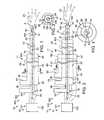
- FIG. 1is a schematic illustration of multiple-wire systems according to the present disclosure that include two concentric wires.
- FIG. 2is a schematic cross-sectional illustration of the systems of FIG. 1 taken along line 2 - 2 .
- FIG. 3is a schematic illustration of multiple-wire systems according to the present disclosure that include three concentric wires.
- FIG. 4is a schematic cross-sectional illustration of the systems of FIG. 3 taken along line 4 - 4 .
- FIG. 5is a schematic cross-sectional illustration of a wire tip of a multiple-wire system according to the present disclosure, the wire tip including a portion of a radio-frequency device therein.
- FIG. 6is a schematic cross-sectional illustration of a wire tip of a multiple-wire system according to the present disclosure, the wire tip having a mandril extending therethrough and a portion of a radio-frequency device mounted on the distal end of the mandril.
- FIG. 7is a schematic cross-sectional illustration of a portion of a wire of a multiple-wire system according to the present disclosure, the wire including an insulative coating and an exposed tip.
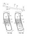
- FIG. 8is an isometric side view of a portion of a multiple-wire system according to the present disclosure, the system including wires that include a plurality of wound wire strands.
- FIG. 9is an isometric side view of a wire according to the present disclosure, the wire tapered and including a plurality of wound wire strands.
- FIG. 10is a cross-sectional side view of a multiple-wire system according to the present disclosure, the system including two concentric wires, each wire including a handle.
- FIG. 11is a cross-sectional side view of a multiple-wire system according to the present disclosure, the system including three concentric wires, each wire including a handle.
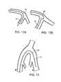
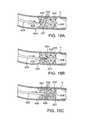
- FIGS. 12A and 12Bare cross-sectional views of two wires of a multiple-wire system according to the present disclosure, the wires extending around a bend adjacent a bifurcation in a human blood vessel, showing the difference in performance between a transitionless wire ( 12 A) and a wire with a transition ( 12 B).
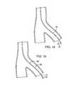
- FIG. 13is a cross-sectional view, from a perspective of facing the patient, of contralateral access by a multiple-wire system according to the present disclosure from the right iliac artery to the left iliac artery.
- FIG. 14is a cross-sectional view of a two-wire system according to the present disclosure being maneuvered into a branch of a blood vessel.
- FIG. 15is a cross-sectional view of a two-wire system according to the present disclosure with a catheter being maneuvered into a branch of a blood vessel.
- FIG. 16is a cross-sectional view of a chronic total occlusion within a blood vessel that includes a plurality of microchannels.
- FIG. 17depicts a tapered wire, similar to the one shown in FIG. 9 except without a textured surface.
- FIGS. 18A-Cdepict a method of using a first wire having a tapered portion to gradually dilate a microchannel of a chronic total occlusion.
- FIGS. 19A-Bdepict a method of using a first wire and a capture device to traverse a chronic total occlusion.
- FIGS. 20A-Bare cross-sectional views of the vessel being treated using a method similar to that depicted in FIGS. 19A-B .
- FIG. 21depicts another method of using a first wire and a capture device with a receptor to traverse a chronic total occlusion.
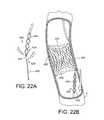
- FIGS. 22A-Bdepict another method of using a first wire and a retractable-loop snare to traverse a chronic total occlusion.
- FIGS. 23A-Bdepict another method of using a first wire and a capture device inserted from the same direction as the first wire to traverse a chronic total occlusion.
- FIGS. 1-4multiple-wire systems are schematically illustrated in FIGS. 1-4 and are generally indicated at 10 .
- Systems 10may include two or more concentric wires 11 .
- Wires 11may additionally or alternatively be described as guidewires.
- Wires 11may (but are not required to) be constructed at least partially with a hydrophilic material (e.g., coated with a polytetrafluoroethylene (PTFE) or plastic covering) selected for a particular procedure being performed.
- PTFEpolytetrafluoroethylene
- the term ‘hydrophilic’refers to a property of a material where the material becomes slippery when subjected to a fluid, such as a liquid. Accordingly, wires 11 made of a hydrophilic material may be less likely to snag within a blood vessel or to accidentally poke through the wall of a blood vessel, such as when the wire is being routed around a bend or turn of a vessel.
- Multiple wire systemsmay (but are not required to) further include a treatment device 51 in the form of a radio-frequency device 151 operatively connected to one or more of wires 11 .
- a radio-frequency device 151may be referred to as radio-frequency, or RF, wire systems 100 .
- systems 10may include a treatment device 51 that incorporates a laser energy device, an optical coherent reflectometry (OCR) device, an ultrasound device, or any other device suitable for mounting on a wire or catheter and for controlling from outside the body while inserted in the body.
- OCRoptical coherent reflectometry
- a wire 11may have a generally cylindrical outer surface that defines an outer diameter. Additionally or alternatively, a wire 11 may have an outer surface that generally tapers at least partially along its overall length. For example, a wire may have a greater diameter at its proximal end than at its distal end. Such a wire may have a proximal end diameter equal to about 0.061 cm (0.024 inches) and a distal end diameter equal to about 0.025 cm (0.01 inches); however, other configurations are equally within the scope of the present disclosure. Additionally or alternatively, a wire may have a generally cylindrical outer surface for a portion of its length and a tapered outer surface for another portion of its length. Other configurations are equally within the scope of the present disclosure, and the schematic illustrations of FIGS. 1-4 are not to be interpreted as limiting wires 11 to having only cylindrical outer surfaces with constant outer diameters.
- FIGS. 1 and 2An example of a two-wire system is schematically illustrated in FIGS. 1 and 2 , and an example of a three-wire system is schematically illustrated in FIGS. 3 and 4 . Systems with more than three wires are equally within the scope of the present disclosure.
- System 200includes a first, inner wire 12 , a second wire 26 through which first wire 12 extends, and a radio-frequency device 151 operatively connected to one or both of the first and second wires.
- First wire 12includes a distal end 14 and a proximal end 16 , and has a length that may be selected for a particular type of procedure to be conducted in a human blood vessel.
- first wire 12may be between about 150 cm and about 300 cm; however, other lengths are equally within the scope of the present disclosure.
- Inner wire 12may (but is not required to) include an opening 18 adjacent distal end 14 , an opening 20 adjacent proximal end 16 , and a central lumen 22 extending between the proximal and distal openings, which may define an inner diameter of first wire 12 .
- Embodiments that include a lumen 22 within first wire 12may be used to deliver a fluid 23 (including liquids and gases), such as (but not Limited to) water, saline, compressed air or other gas, pharmaceuticals (whether in liquid or gas form), etc., to a site within a blood vessel.
- a delivered fluidmay be used to break up an occlusion and/or to expand an already partially open occlusion.
- lumen 22may (but is not required to) be coated with a fluid-impervious coating to prevent the migration of fluid 23 through the wall of first wire 12 when a system is used to deliver a fluid to a site within a blood vessel.
- First wire 12may (but is not required to) have a generally cylindrical outer surface 24 defining an outer diameter, which may be between about 0.010 cm (0.004 inches) and about 0.036 cm (0.014 inches), or may be larger or smaller as selected for a particular procedure and for compatibility with other wires, catheters, sheaths, and other equipment.
- first wire 12may have an outer surface 24 that tapers at least partially along its length.
- first wire 12may include an outer surface 24 that has a textured surface that is configured to provide a mechanism for aiding with the insertion and/or passage of wire 12 through a blood vessel in response to an operator manipulating the wire (e.g., by twisting it), as discussed in more detail below in reference to FIG. 8 .
- Inner wire 12may be provided with a handle portion 50 adjacent proximal end 16 that a user (e.g., a physician) may use in manipulating the wire about and along a central axis A of the wire. Handle portion 50 may (but is not required to) be removable in some embodiments. Wire 12 may be constructed with a hydrophilic material (e.g., coated with a Teflon or plastic covering) selected for a particular procedure being performed.
- a hydrophilic materiale.g., coated with a Teflon or plastic covering
- Second wire 26may be constructed to be deployed over first wire 12 . Additionally or alternatively, second wire 26 may be described as being constructed to receive first wire 12 , such that first wire 12 is deployed within second wire 26 after second wire 26 has already been deployed within a blood vessel.
- Second wire 26includes a distal end 28 and a proximal end 30 , and has a length that is compatible with first wire 12 , for example, less than the length of first wire 12 .
- the length of second wire 26may be selected for a particular type of procedure to be conducted in a human blood vessel. For example, the length may be between about 125 cm and about 275 cm; however, other lengths are equally within the scope of the present disclosure.
- Second wire 26includes an opening 34 adjacent distal end 28 , an opening 36 adjacent proximal end 30 , and a central lumen 32 extending between the distal and proximal openings, which may define an inner diameter of second wire 26 .
- central lumen 32 of second wire 26may be configured to compliment the outer surface 24 of inner first wire 12 .
- the central lumen of the second wiremay (but is not required to) be configured with a corresponding textured inner surface that is adapted to compliment the textured outer surface of the inner wire, as discussed in more detail below in reference to FIG. 8 .
- Second wire 26may have a generally cylindrical outer surface 38 defining an outer diameter, which may be between about 0.052 cm (0.008 inches) and about 0.089 cm (0.035 inches), or may be larger or smaller as selected for a particular procedure and for compatibility with other wires, catheters, sheaths, and other equipment.
- second wire 26may have an outer surface 38 that tapers at least partially along its length.
- second wire 26may include a textured outer surface that is configured to provide a mechanism for aiding with the insertion and/or passage of wire 26 through a blood vessel in response to an operator manipulating the wire (e.g., by twisting it), as discussed in more detail below in reference to FIG. 8 .
- Second wire 26may be provided with a handle portion 54 adjacent proximal end 30 that a physician may use in manipulating the wire about and along central axis A.
- Handle portion 54may (but is not required to) be removable in some embodiments.
- Second wire 26may (but is not required to) have a rigidity selected to be greater than that of first wire 12 , thus providing the system with an overall variable rigidity which depends on the extent to which the first wire extends out of the second wire.
- wires 11may (but are not required to) be constructed in sections.
- the wire(s)may be constructed without transitions between the sections.
- wires 11may be used in crossing a bifurcation in the blood vessel, and may be provided with a rigidity selected to allow the bifurcation crossing. Rigidity may be controlled by the use of braiding or the selection of various materials. For example, nitinol is flexible, but it becomes stiffer as more stainless steel is added.
- RF wire systems 100may include an RF device 151 .
- Such devicesmay include an RF-generating device 152 operatively connected to one or more of wires 11 and configured to generate radio-frequency energy that may be delivered to at least a portion of one or more of wires 11 .
- RF-generating device 152may deliver RF energy to first wire 12 .
- RF-generating device 152may deliver RF energy to second wire 26 . Examples of RF-generating devices and RF devices in general are disclosed in U.S. Pat. Nos. 6,190,379, 6,485,489, and 7,229,469, and U.S. patent application Ser. Nos.
- RF-generating devices and RF devicesin general include the Boa SystemTM, the Boa-Surg DeviceTM, and the Boa-Cathe DeviceTM offered by QuantumCor, Inc. of San Clemente, Calif. and the Safe-Cross® RF Crossing Wire device offered by IntraLuminal Therapeutics, Inc. of Carlsbad, Calif. Such devices may be used with, or adapted for use with, systems 100 according to the present disclosure to provide the RF energy that may be delivered to one or more of wires 11 .
- one or more of wires 11may include an RF-delivery tip 154 positioned at the distal end thereof.
- Such delivery tipsmay be configured to receive RF energy from RF-generating device 152 and deliver the RF energy to an occlusion, for example, or other blockage or structure to be ablated during a procedure.
- Various configurations of delivery tipsare within the scope of the present disclosure and are discussed in more detail below. Delivery tips 154 may be described as comprising a portion of an RF device 151 .
- the RF energymay be routed to the RF delivery tip(s) in any number of ways that may be appropriate for a specific configuration of system 100 .
- the bulk of a wire 11e.g., the conductive portions thereof
- the RF energymay be delivered solely to a tip portion via a wire or other structure that is generally insulated from the bulk of the wire 11 to which a specific tip 154 is being charged.
- the given wiremay be coated with an insulative covering to avoid transfer of the RF energy to an adjacent concentric wire 11 , for example, as schematically illustrated in FIG. 2 at 156 as coating the outer surface 24 of first wire 12 .
- the lumen of a given wire 11may be coated with an insulative lining, for example, as schematically illustrated in FIG. 2 at 158 as coating the central lumen 22 of first wire 12 .
- PTFEpolytetrafluoroethylene
- systems 10 according to the present disclosuremay (but are not required to) further include a mandril 160 configured to extend through first wire 12 .
- Mandril 160may be considered a wire 11 according to the present disclosure; however, mandril 160 may or may not include a central lumen, and may generally be a cylindrical wire adapted to provide treatment or diagnostic abilities for systems 10 .
- mandril 160may be charged with RF energy for the ablation of an occlusion or other tissue. Examples of mandrils 160 are disclosed in U.S. Pat. No. 6,190,379, incorporated above.
- FIGS. 3 and 4schematically illustrate an example of a three-wire RF wire system 300 .
- systems 300include a first wire 12 , a second wire 26 through which first wire 12 extends, and a radio-frequency device 151 .
- a third wire 40is also provided that may be constructed to be deployed over second wire 26 . Additionally or alternatively, third wire 40 may be described as being constructed to receive second wire 26 , such that second wire 26 is deployed within third wire 40 after third wire 40 has already been deployed within a blood vessel.
- Third wire 40includes a distal end 42 and a proximal end 44 , and has a length that is compatible with first and second wires 12 , 26 , for example less than that of second wire 26 .
- the length of third wire 40may be selected for a particular type of procedure to be conducted in a human blood vessel. For example, the length may be between about 100 cm and 250 cm; however, other lengths are equally within the scope of the present disclosure.
- Third wire 40includes an opening 46 adjacent distal end 42 , an opening 48 adjacent proximal end 44 , and a central lumen 49 extending between the proximal and distal openings, which may define an inner diameter of third wire 40 .
- central lumen 49 of third wire 40may be configured to compliment the outer surface 38 of second wire 26 .
- the central lumen of the third wiremay (but is not required to) be configured with a corresponding textured inner surface that is adapted to compliment the textured outer surface of the second wire, as discussed in more detail below in reference to FIG. 8 .
- Third wire 40may have a generally cylindrical outer surface 47 defining an outer diameter, which may be between about 0.025 cm (0.010 inches) and about 0.089 cm (0.035 inches), or may be larger or smaller as selected for a particular procedure and for compatibility with other wires, catheters, sheaths, and other equipment.
- third wire 50may have an outer surface 47 that tapers along at least a portion of its length.
- third wire 40may include a textured outer surface that is configured to provide a mechanism for aiding with the insertion and/or passage of third wire 40 through a blood vessel in response to a user manipulating the wire (e.g., by twisting it), as discussed in more detail below in reference to FIG. 8 .
- Third wire 40may be provided with a handle portion 56 adjacent proximal end 44 that a physician may use in manipulating the wire about and along central axis A.
- Handle portion 56may (but is not required to) be removable in some embodiments.
- Third wire 40may (but is not required to) have a rigidity selected to be greater than that of the first and second wires, thus providing the system with an overall variable rigidity that depends on the extent to which the second wire extends out of the third wire, and the extend to which the first wire extends out of the second wire.
- wires 11may include an RF-delivery tip 154 positioned at the distal end thereof.
- delivery tips 154are illustrated in FIGS. 5-7 .
- wire 11includes an RF energy collection structure 162 in the form of a plurality of spaced apart rings 164 embedded within tip 154 .
- collection structure 162may take the form of a coil. Rings 164 , or similarly a coil, may be configured to absorb RF energy delivered to tip 154 by an associated RF-generating device through the bulk of wire 11 or through an associated wire or other structure that is generally insulated from the bulk of wire 11 .
- a non-exclusive example of a material that may be appropriate for the construction of rings 164 , or a coil,is gold.
- Other configurations of RF energy collection and delivery structureare equally within the scope of the present disclosure and may be incorporated into systems 10 .
- FIG. 6illustrates a non-exclusive example of a system 10 that includes a mandril 160 extending through a first wire 12 .
- the distal end of the mandrilmay include radio-frequency energy collection structure 162 in the form of a plurality of spaced apart rings 164 , or in the form of a coil, wrapped around the distal end of the mandril.
- FIG. 7illustrates yet another non-exclusive example of a delivery tip 154 .
- the wire 11includes an insulative covering 156 as discussed above, with the covering leaving at least a portion of the distal end of wire 11 exposed.
- the entire wire 11or at least the bulk of wire 11 , may be charged with RF energy, while only the distal end is exposed within a blood vessel when being used, and therefore may be used to ablate an occlusion or other tissue therein.
- wires 11 of systems 10may (but are not required to) include textured outer surfaces configured to provide a mechanism for aiding with the insertion of a wire through a blood vessel, or occlusion therein, in response to an operator manipulating the wire.
- one or more of the outer surfacesmay have a spiraled, screw-like, or threaded configuration that aids with the insertion and/or passage of a wire through a blood vessel in response to an operator twisting the wire 11 .
- a wire 11may be formed by a plurality of wound or braided wires or wire strands. A non-exclusive example of a system 10 including such structure is illustrated in FIG. 8 .
- a system 10includes a first wire 12 and a second wire 26 , constructed of a plurality of smaller wires wound about their respective lumens. Accordingly, outer surface 24 of first wire 12 and outer surface 38 of second wire 26 provide a screw-like or threaded configuration. As illustrated in dashed lines, systems 10 having wires 11 with textured outer surfaces are not limited to two-wire systems, and may further include a third wire 40 . Additional wires beyond three are equally within the scope of the present disclosure.
- an outer wirei.e., a second, third, or further wire having a concentric wire extending therethrough
- the central lumen of the outer wiremay be configured with a corresponding textured inner surface (e.g., in the form of female threads, or the like) that is adapted to compliment the textured outer surface of the inner wire, and thereby provide for relative screw-like displacement of the inner wire within the outer wire when a user twists the inner wire within the outer wire.
- Multiple-wire systems having wires 11 with textured outer surfaces and an inner wire with a central lumenmay be particularly well suited for the delivery of a fluid to a site within a blood vessel.
- the fluidmay be generally prevented from leaking through the structure that defines the textured outer surface.
- the textured outer surface of a wireis defined by a plurality of wound or braided wire strands, depending on the fluid being used for a particular procedure, the fluid may tend to leak through the wound or braided wire strands.
- fluid that manages to leak through the structure of the inner wiremay generally be contained by the outer one or more wires.
- the central lumen of the inner wiremay be lined with a coating (e.g., polytetrafluoroethylene (PTFE), plastic, or other suitable material) to generally prevent migration of the fluid through the wall of the inner wire.
- a tubee.g., constructed of PTFE, plastic, or other suitable material
- PTFEpolytetrafluoroethylene
- embodiments that include wires with textured surfacesmay include RF-delivery tips 154 for the delivery of RF energy within a blood vessel.
- the distal openings to wires 11may be defined by a cutting edge configured to aid in the passage of wires 11 through blood vessels and through occlusions, other blockages, or tissue therein.
- distal opening 18 of first wire 12may be defined by a cutting edge 166
- distal opening 34 of second wire 26may be defined by a cutting edge 168
- distal opening 46 of third wire 40may be defined by a cutting edge 170 .
- Such cutting edgesmay simply be thinner than the thickness of the rest of the wire 11 , or alternatively may be defined by serrations or other structure configured to aid in the cutting through an occlusion, blockage, or other tissue.
- Such configurationsmay be particularly useful in embodiments that include a textured outer surface of a wire 11 , as discussed above. Accordingly, as a user inserts a wire 11 through a blood vessel and reaches an occlusion or other blockage within a blood vessel, the user may twist the wire causing the distal opening to cut through the blockage and thereby facilitate further insertion of the wire, with or without the addition of RF energy.
- Wires 11 according to the present disclosureare not limited to being cylindrical, and as discussed above and illustrated in FIG. 9 , may have portions that are generally tapered or cone-shaped.
- the non-exclusive example illustrated in FIG. 9further includes a textured outer surface, although other configurations of tapered wires, including wire having smooth outer surfaces, are equally within the scope of the present disclosure.
- Systems 10may include an inner wire 12 having a distal end 14 and a proximal end 16 .
- Inner wire 12has a length that may be selected for a particular type of procedure to be conducted in a human blood vessel, e.q., between about 180 cm and about 300 cm.
- Inner wire 12may include an opening 18 adjacent distal end 14 and an opening 20 adjacent proximal end 16 , and a central lumen 22 extending between the proximal and distal openings.
- Central lumen 22defines an inner diameter for wire 12
- wire 12also has a generally cylindrical outer surface 24 defining an outer diameter.
- the outer diameter of inner wire 12may be between about 0.010 cm (0.004 inches) and about 0.036 cm (0.014 inches), and my be any size therebetween , or larger or smaller as selected for the desired procedure and for campatibility with other wires, catheters, sheaths, and other equipment.
- Inner wire 12may be provided with a handle 50 , preferably (but not required to be) removable, adjacent proximal end 16 that a physician may use in manipulating the wire about and along a central axis A of the wire.
- Wire 12is may be constructed with a hydrophilic material selected for the particular procedure. For example, coating with a polytetrafluoroethylene (PTFE) or plastic covering makes a wire hydrophilic.
- PTFEpolytetrafluoroethylene
- Wire 12may be constructed without transitions between sections, if it includes any sections, of the wire.
- Inner wire 12may be used in crossing a bifurcation in a blood vessel, and may be provided with a rigidity selected to allow the bifurcation crossing. Rigidity may be controlled by the use of braiding or the selection of various materials. For example, nitinol is flexible, but it becomes stiffer as more stainless steel is added.
- inner wire 12may optionally include a treatment or a diagnostic device 52 (e.g., in the form of an RF-delivery tip 154 as discussed above), typically Located at the distal end 14 of wire 12 .
- a diagnostic device 52e.g., in the form of an RF-delivery tip 154 as discussed above
- device 52may be located in a more proximal position on wire 12 , or may be located on the other wires or catheter to be described below.
- Device 52may be any type of device useful for treating or diagnosing conditions in blood vessels, such as a radio-frequency energy device, a laser energy device, an optical coherent reflectometry (OCR) device, an ultrasound device, or any other device suitable for mounting on a wire or catheter and for controlling from outside the body while inserted in the body.
- OCRoptical coherent reflectometry
- a second wire 26preferably constructed to be deployed over inner wire 12 , includes a distal end 28 and a proximal end 30 and a length preferably selected to be compatible with inner wire 12 .
- a central lumen 32 of wire 26extends between a distal opening 34 and a proximal opening 36 .
- second wire 26may include an RF-delivery tip 154 at its distal end.
- Central lumen 32 of second wire 26defines an inner diameter for the wire.
- Wire 26may have a generally cylindrical outer surface 38 defining an outer diameter.
- the outer diameter of wire 26may be between about 0.020 cm (0.008) inches and about 0.089 cm (0.035 inches), and may be any size therebeween, or larger or smaller as selected for the desired procedure and for compatibility with other wires, catheters, sheaths, and other equipment.
- Wire 26may be provided with a handle 54 , preferably (but not required to be) removable, adjacent proximal end 30 that the physician may use in manipulating the wire about and along a central axis A of the wire.
- Second wire 26may have a rigidity selected to be greater than that of inner wire 12 , thus providing the system with an overall variable rigidity which depends on the extent to which the inner wire extends out of the second wire.
- System 10may also include a third or outer wire 40 , as shown in FIG. 11 , having proximal and distal ends with openings and a central lumen communicating therebetween, inner and outer diameters, and a generally cylindrical outer surface as for the other wires.
- third wire 40is sized to fit over the second wire and includes a handle 56 , preferably (but not required to be) removable, coupled adjacent the proximal end for manipulation of the third wire about and along central axis A.
- Third wire 40may have a rigidity selected to be greater than the rigidity of the first wire and greater than the rigidity of the second wire, thus providing the system with an overall variable rigidity which depends on the extent to which the inner wire extends out of the second wire, and the extent to which the second wire extends out of the third wire.
- Third wire 40may also include an RF-delivery tip 154 at its distal end.
- Third wire 40may have an outer diameter between about 0.025 cm (0.010 inches) and about 0.089 cm (0.035 inches), and may be any size therebetween, or larger or smaller as selected for the desired procedure and for compatibility with other wires, catheters, sheaths, and other equipment.
- the length of the third wireis less than the length of the second wire, and the length of the second wire is less than that of the inner wire.
- the multiple guidewire systemmay be combined with a catheter, such as catheter 58 that can be inserted over the wires, as shown in FIG. 13 .
- a cathetersuch as catheter 58 that can be inserted over the wires, as shown in FIG. 13 .
- a cathetermay include a balloon and a stent placement apparatus.
- the catheter or one or more of the wiresmay be provided with a radio-frequency energy device, a laser energy device, and/or an optical reflectometry device for applying treatment within the blood vessel, or with other devices, including diagnostic devices such as ultrasound.
- any of the handles of the first, second, and third wiresmay be used to manipulate all three wires, and also the wires may be manipulated relative to one another by simultaneous use of two or three of the handles.
- handles 50 and 54may include one or more forward-facing wings 60 , which interlock with corresponding notches 62 in handles 54 and 56 , when the handles are pushed together. When the wings and notches interlock, rotational movement of one handle will also rotate the Wire attached to the interlocked handle.
- any other type of selective interlockingmay be used, or the friction between the wires may provide for simultaneous movement, unless the handles are separately manipulated.
- the length of the first wiremay be between about 180 cm and about 300 cm, but may be other sizes as desired for particular procedures.
- the length of the second wiremay be about 5 cm less than the first wire, and the length of the third wire may be about 5 cm less than the second wire.
- FIGS. 12A and 12Bshow two examples of a two-guidewire system, including inner wire 12 and outer wire 26 , being used to extend around a bend and into one channel at a bifurcation in a human blood vessel.
- FIG. 12Ashows the performance of a transitionless wire, which can extend around the corner without doubling over
- FIG. 12Bshows the performance of a wire with a transition, which tends to double over.
- the transitiontypically occurs where two materials that are different in hydrophilicity or stiffness are directly joined, and a transitionless wire is typically provided by gradually changing the hydrophilicity or stiffness, or by other methods of preventing the abrupt transition.
- FIG. 13shows contralateral access by the guidewire system from the right iliac artery R to the left iliac artery L.
- FIG. 14shows a two-wire guidewire system, including inner wire 12 and outer wire 26 , and treatment/diagnostic device 52 , being maneuvered into a branch of a blood vessel.
- FIG. 15shows the two-wire guidewire system with catheter 58 being maneuvered into a branch of a blood vessel.
- FIG. 16depicts a cross-sectional view of a CTO 400 in a blood vessel V.
- CTO 400includes one or more microchannels 402 that may be expanded to gain access through CTO 400 .
- microchannel 402may be expanded to form a channel through CTO 400 into which a needle or other instrument can be inserted.
- FIGS. 17-23Devices and methods for performing such a procedure utilizing various occlusion-penetrating devices are depicted in FIGS. 17-23 .
- CTO 400has a proximal surface 404 and an opposite distal surface 406 (see, e.g., FIGS. 19A and B).
- FIG. 17depicts an example apparatus including a first wire 420 having a proximal end 422 operable by a physician, a distal end 424 and a gradually tapered portion 426 adjacent distal end 424 .
- Gradually tapered portion 426terminates at a sharp tip 427 at distal end 424 .
- first wire 420may include a first magnet 428 .
- First wire 420may be a wire that is incorporated into one of the multiple-wire systems described above.
- wire 420may be the same as inner wire 12 shown in FIGS. 1 and 3 .
- first wire 420may include a radio-frequency device 151 and RF-delivery tip 154 adjacent its distal end 424 for breaking apart at least a portion of CTO 400 (see FIGS. 1 , 3 , 5 , 7 and 8 ).
- FIGS. 18A-CA particularly effective method of penetrating an occlusion is depicted in FIGS. 18A-C .
- first wire 420is inserted into the blood vessel V to a position where distal tip 424 of first wire 420 is adjacent a microchannel 402 of CTO 400 .
- First wire 420is then advanced towards CTO 400 so that gradually tapered portion 426 gradually dilates microchannel 402 ( FIGS. 18B and C) and eventually gains access through CTO 400 .
- First wire 420may be inserted at least partially or all of the way through occlusions in blood vessels in ways other than directly through CTO 400 .
- first wire 420traverses CTO 400 in vessel V via the subintimal space in the vessel wall adjacent CTO 400 .
- First wire 420may also be inserted directly into an occlusion (e.g., into a microchannel 402 ), or through the space between the side of an occlusion and the wall of the blood vessel V.
- a capture device 430may be deployed to draw distal end 424 of first wire 420 through CTO 400 .
- capture device 430includes a second wire 432 that is inserted from the opposite side of CTO 400 as first wire 420 towards distal surface 406 so that second wire 432 can be used to draw distal end 424 of first wire 420 to a position distal of distal surface 406 of CTO 400 .
- first wire 420 and/or second wire 432include a first magnet 428 and/or a second magnet 434 . Each of these magnets may be adapted to attract, or possibly repel, the other magnet.
- FIGS. 20A and Bdepict cross sectional views of the vessel being treated in FIG. 19A
- first wire 420 and second wire 432are inserted into the subintimal space of blood vessel V. However, the wires are at different points of the circumference of the vessel wall.
- first wire 420includes first magnet 428 and second wire 432 includes second magnet 434 , and the magnets are operated to draw first wire 420 and second wire 432 together, as shown in FIG. 20B .
- the reference numerals 420 , 428 , 432 and 434are point at the first and second wires generally, and not to any particular portion of the wires (because, for example, the magnets 428 and 434 can be at various positions near the distal tips of the wires, or the distal tips themselves may be magnetic).
- capture device 430includes other features for capturing and/or drawing first wire 420 through an occlusion.
- capture device 430includes a receptor 436 for receiving distal end 424 of first wire 420 .
- Receptor 436includes a distal opening 438 , a proximal end 440 and a channel 442 therebetween.
- channel 442may be tapered in a direction from distal opening 438 to proximal end 440 .
- receptor 436includes a magnet 434 adapted to attract distal end 424 (which may contain a magnet 428 ) of first wire 420 along channel 442 towards proximal end 440 .
- a receptoris described in U.S. Pat. No. 7,374,567 to Heuser, the disclosure of which is incorporated by reference for all purposes.
- FIGS. 22A and Bdepict another embodiment of capture device 430 comprising a retractable loop snare 444 .
- FIG. 22Adepicts first wire 420 and retractable loop snare 444 outside of a living body and in close proximity.
- first wire 420 and retractable loop snare 444include first magnet 428 and second magnet 434 , respectively, but it should be understood that magnets are not required.
- Retractable loop snares suitable for the methods described hereinare described in U.S. Pat. No. 6,554,842 to Heuser, the disclosure of which is incorporated by reference herein for all purposes.
- FIG. 22Bdepicts first wire 420 being captured by retractable loop snare 444 and drawn through the subintimal space proximate CTO 400 .
- first wire 420 and capture device 430are advanced towards CTO 400 from opposite directions. However, this is not required, and as will be described below, first wire 420 and capture device 430 may be inserted into vessel V towards CTO 400 from the same direction.
- first wire 420is inserted partially through CTO 400 and capture device 430 , in the form of second wire 432 , is inserted into subintimal space adjacent CTO 400 .
- First wire 420 and second wire 432include first magnet 428 and second magnet 434 , respectively, so that first wire 420 and second wire 432 are attracted towards one another. This magnetic attraction is utilized to draw the wires together through CTO 400 in the directions indicated by the arrows in FIG. 23A , which may also break up a portion of CTO 400 . As a result, the wires will be immediately adjacent, as shown in FIG. 23B .
Landscapes
- Health & Medical Sciences (AREA)
- Life Sciences & Earth Sciences (AREA)
- Engineering & Computer Science (AREA)
- Public Health (AREA)
- General Health & Medical Sciences (AREA)
- Biomedical Technology (AREA)
- Heart & Thoracic Surgery (AREA)
- Veterinary Medicine (AREA)
- Animal Behavior & Ethology (AREA)
- Hematology (AREA)
- Anesthesiology (AREA)
- Surgery (AREA)
- Pulmonology (AREA)
- Biophysics (AREA)
- Physics & Mathematics (AREA)
- Cardiology (AREA)
- Molecular Biology (AREA)
- Medical Informatics (AREA)
- Plasma & Fusion (AREA)
- Otolaryngology (AREA)
- Nuclear Medicine, Radiotherapy & Molecular Imaging (AREA)
- Media Introduction/Drainage Providing Device (AREA)
- Surgical Instruments (AREA)
Abstract
Description
Claims (11)
Priority Applications (4)
| Application Number | Priority Date | Filing Date | Title |
|---|---|---|---|
| US12/356,446US8545418B2 (en) | 2004-08-25 | 2009-01-20 | Systems and methods for ablation of occlusions within blood vessels |
| PCT/US2010/021414WO2010090819A1 (en) | 2009-01-20 | 2010-01-19 | Systems and methods for ablations of occlusions within blood vessels |
| JP2011548058AJP2012515620A (en) | 2009-01-20 | 2010-01-19 | System and method for resection of an obstruction in a blood vessel |
| EP10738913AEP2389125A4 (en) | 2009-01-20 | 2010-01-19 | Systems and methods for ablations of occlusions within blood vessels |
Applications Claiming Priority (3)
| Application Number | Priority Date | Filing Date | Title |
|---|---|---|---|
| US10/927,340US7402141B2 (en) | 2003-08-27 | 2004-08-25 | Catheter guidewire system using concentric wires |
| US12/043,675US20080154153A1 (en) | 2004-08-25 | 2008-03-06 | Multiple-wire systems and methods for ablation of occlusions within blood vessels |
| US12/356,446US8545418B2 (en) | 2004-08-25 | 2009-01-20 | Systems and methods for ablation of occlusions within blood vessels |
Related Parent Applications (1)
| Application Number | Title | Priority Date | Filing Date |
|---|---|---|---|
| US12/043,675Continuation-In-PartUS20080154153A1 (en) | 2004-08-25 | 2008-03-06 | Multiple-wire systems and methods for ablation of occlusions within blood vessels |
Publications (2)
| Publication Number | Publication Date |
|---|---|
| US20090125045A1 US20090125045A1 (en) | 2009-05-14 |
| US8545418B2true US8545418B2 (en) | 2013-10-01 |
Family
ID=42542349
Family Applications (1)
| Application Number | Title | Priority Date | Filing Date |
|---|---|---|---|
| US12/356,446Active2026-09-25US8545418B2 (en) | 2004-08-25 | 2009-01-20 | Systems and methods for ablation of occlusions within blood vessels |
Country Status (4)
| Country | Link |
|---|---|
| US (1) | US8545418B2 (en) |
| EP (1) | EP2389125A4 (en) |
| JP (1) | JP2012515620A (en) |
| WO (1) | WO2010090819A1 (en) |
Cited By (14)
| Publication number | Priority date | Publication date | Assignee | Title |
|---|---|---|---|---|
| US20100292685A1 (en)* | 2007-09-26 | 2010-11-18 | Retrovascular, Inc. | Recanalizing occluded vessels using radiofrequency energy |
| US20170000519A1 (en)* | 2015-06-30 | 2017-01-05 | Furqan Tejani | Interventional wire capture device and methods of use |
| US9561073B2 (en) | 2007-09-26 | 2017-02-07 | Retrovascular, Inc. | Energy facilitated composition delivery |
| US9706998B2 (en) | 2013-03-08 | 2017-07-18 | Limflow Gmbh | Methods for targeting body passages |
| US9782201B2 (en) | 2006-04-20 | 2017-10-10 | Limflow Gmbh | Methods for fluid flow through body passages |
| US10543308B2 (en) | 2017-04-10 | 2020-01-28 | Limflow Gmbh | Methods for routing a guidewire from a first vessel and through a second vessel in lower extremity vasculature |
| US10596356B2 (en) | 2014-06-19 | 2020-03-24 | Limflow Gmbh | Methods for placing a stent-graft to cover collateral vessels in lower extremity vasculature |
| WO2020117865A1 (en)* | 2018-12-03 | 2020-06-11 | The Board Of Regents Of The University Of Texas System | Systems and methods for treating chronic total occlusion of an artery |
| US10835367B2 (en) | 2013-03-08 | 2020-11-17 | Limflow Gmbh | Devices for fluid flow through body passages |
| WO2020234754A1 (en) | 2019-05-20 | 2020-11-26 | Kum Wei Cheong Steven | Extravascular bypass systems and methods |
| US11116943B2 (en) | 2018-10-09 | 2021-09-14 | Limflow Gmbh | Methods for accessing pedal veins |
| US11446170B2 (en) | 2004-09-08 | 2022-09-20 | Limflow Gmbh | Minimally invasive surgical apparatus and methods |
| US11612397B2 (en) | 2019-11-01 | 2023-03-28 | Limflow Gmbh | Devices and methods for increasing blood perfusion to a distal extremity |
| US12440649B2 (en) | 2019-12-03 | 2025-10-14 | The Board Of Regents Of The University Of Texas System | Systems and methods for treating chronic total occlusion of an artery |
Families Citing this family (8)
| Publication number | Priority date | Publication date | Assignee | Title |
|---|---|---|---|---|
| US9387308B2 (en)* | 2007-04-23 | 2016-07-12 | Cardioguidance Biomedical, Llc | Guidewire with adjustable stiffness |
| US9283034B2 (en)* | 2007-09-26 | 2016-03-15 | Retrovascular, Inc. | Recanalization system using radiofrequency energy |
| US8728011B2 (en) | 2011-07-22 | 2014-05-20 | Michael D. Khoury | Multi wire sheath |
| US10206584B2 (en) | 2014-08-08 | 2019-02-19 | Medlumics S.L. | Optical coherence tomography probe for crossing coronary occlusions |
| GB201418479D0 (en)* | 2014-10-17 | 2014-12-03 | Creo Medical Ltd | Cable for conveying radiofrequency and/or microwave frequency energy to an electrosurgical instrument |
| US10383683B2 (en)* | 2014-10-20 | 2019-08-20 | Asahi Medical Technologies, Inc. | Redirecting delivery catheter and methods of use thereof |
| CA2994368A1 (en)* | 2015-08-23 | 2017-03-02 | CardioSert Ltd. | Double concentric guidewire |
| JP2022550708A (en)* | 2019-09-26 | 2022-12-05 | コーニンクレッカ フィリップス エヌ ヴェ | Multi-segment intraluminal imaging device and related devices, systems and methods |
Citations (244)
| Publication number | Priority date | Publication date | Assignee | Title |
|---|---|---|---|---|
| US2729211A (en) | 1950-07-07 | 1956-01-03 | Peter Josef | Device for examining the condition of the stomach |
| US3751305A (en) | 1971-03-10 | 1973-08-07 | Alco Standard Corp | Adjustable spring-loaded temperature sensing device |
| US3788318A (en) | 1972-06-12 | 1974-01-29 | S Kim | Expandable cannular, especially for medical purposes |
| US3828782A (en) | 1972-04-10 | 1974-08-13 | S Polin | Temporary colostomy tube |
| US3828770A (en) | 1971-02-26 | 1974-08-13 | Ultrasonic Systems | Ultrasonic method for cleaning teeth |
| US4000739A (en) | 1975-07-09 | 1977-01-04 | Cordis Corporation | Hemostasis cannula |
| US4241289A (en) | 1979-03-02 | 1980-12-23 | General Electric Company | Heat sensing apparatus for an electric range automatic surface unit control |
| US4430081A (en) | 1981-01-06 | 1984-02-07 | Cook, Inc. | Hemostasis sheath |
| US4445892A (en) | 1982-05-06 | 1984-05-01 | Laserscope, Inc. | Dual balloon catheter device |
| US4590669A (en) | 1984-11-13 | 1986-05-27 | Netsushin Co., Ltd. | Method of preparing resistance thermometer |
| US4630609A (en) | 1981-05-14 | 1986-12-23 | Thomas J. Fogarty | Dilatation catheter method and apparatus |
| US4634432A (en) | 1985-05-13 | 1987-01-06 | Nuri Kocak | Introducer sheath assembly |
| US4634342A (en) | 1983-06-06 | 1987-01-06 | Rodewald Wilhelm H A | Blower for agricultural spraying |
| US4637814A (en) | 1985-04-05 | 1987-01-20 | Arnold Leiboff | Method and apparatus for intestinal irrigation |
| US4650466A (en) | 1985-11-01 | 1987-03-17 | Angiobrade Partners | Angioplasty device |
| US4650472A (en) | 1985-08-30 | 1987-03-17 | Cook, Incorporated | Apparatus and method for effecting percutaneous catheterization of a blood vessel using a small gauge introducer needle |
| US4682981A (en) | 1984-08-07 | 1987-07-28 | Terumo Kabushiki Kaisha | Medical device |
| US4705511A (en) | 1985-05-13 | 1987-11-10 | Bipore, Inc. | Introducer sheath assembly |
| US4706671A (en) | 1985-05-02 | 1987-11-17 | Weinrib Harry P | Catheter with coiled tip |
| US4744364A (en) | 1987-02-17 | 1988-05-17 | Intravascular Surgical Instruments, Inc. | Device for sealing percutaneous puncture in a vessel |
| US4772258A (en) | 1985-11-22 | 1988-09-20 | Kontron Holding A.G. | Angioplasty catheter |
| US4771777A (en) | 1987-01-06 | 1988-09-20 | Advanced Cardiovascular Systems, Inc. | Perfusion type balloon dilatation catheter, apparatus and method |
| US4796640A (en) | 1984-01-13 | 1989-01-10 | American Hospital Supply Corporation | Apparatus with fast response thermistor |
| US4832688A (en) | 1986-04-09 | 1989-05-23 | Terumo Kabushiki Kaisha | Catheter for repair of blood vessel |
| US4862891A (en) | 1988-03-14 | 1989-09-05 | Canyon Medical Products | Device for sequential percutaneous dilation |
| US4874378A (en) | 1988-06-01 | 1989-10-17 | Cordis Corporation | Catheter sheath introducer |
| US4883460A (en) | 1988-04-25 | 1989-11-28 | Zanetti Paul H | Technique for removing deposits from body vessels |
| US4895564A (en) | 1988-06-08 | 1990-01-23 | Farrell Edward M | Percutaneous femoral bypass system |
| US4911163A (en) | 1986-06-12 | 1990-03-27 | Ernesto Fina | Two ballooned catheter device for diagnostic and operative use |
| US4950257A (en) | 1988-09-15 | 1990-08-21 | Mallinckrodt, Inc. | Catheter introducer with flexible tip |
| US4994071A (en) | 1989-05-22 | 1991-02-19 | Cordis Corporation | Bifurcating stent apparatus and method |
| US5078684A (en) | 1987-09-21 | 1992-01-07 | Terumo Kabushiki Kaisha | Ureter correcting device |
| US5092846A (en) | 1989-11-07 | 1992-03-03 | Sumitomo Bakelite Company Limited | Introducer for medical tube |
| US5112310A (en) | 1991-02-06 | 1992-05-12 | Grobe James L | Apparatus and methods for percutaneous endoscopic gastrostomy |
| US5147336A (en) | 1990-06-05 | 1992-09-15 | The Kendall Company | Adapter kit for a catheter introducer |
| US5163906A (en) | 1988-09-27 | 1992-11-17 | Schneider (Europe) Ag | Dilatation catheter and method for widening of strictures |
| US5176144A (en) | 1989-09-14 | 1993-01-05 | Terumo Kabushiki Kaisha | Cardiac output measuring catheter |
| US5183470A (en) | 1991-03-04 | 1993-02-02 | International Medical, Inc. | Laparoscopic cholangiogram catheter and method of using same |
| US5199939A (en) | 1990-02-23 | 1993-04-06 | Dake Michael D | Radioactive catheter |
| US5207228A (en) | 1992-01-21 | 1993-05-04 | Baxter International Inc. | Dual port thermodilution catheter |
| US5213417A (en) | 1989-08-21 | 1993-05-25 | Nkk Corporation | Apparatus for temperature measurement |
| US5217484A (en) | 1991-06-07 | 1993-06-08 | Marks Michael P | Retractable-wire catheter device and method |
| US5217019A (en) | 1991-12-27 | 1993-06-08 | Abbott Laboratories | Apparatus and method for continuously monitoring cardiac output |
| US5234437A (en) | 1991-12-12 | 1993-08-10 | Target Therapeutics, Inc. | Detachable pusher-vasoocclusion coil assembly with threaded coupling |
| US5242410A (en) | 1991-04-15 | 1993-09-07 | University Of Florida | Wireless high flow intravascular sheath introducer and method |
| US5256141A (en) | 1992-12-22 | 1993-10-26 | Nelson Gencheff | Biological material deployment method and apparatus |
| US5256158A (en) | 1991-05-17 | 1993-10-26 | Act Medical, Inc. | Device having a radiopaque marker for endoscopic accessories and method of making same |
| US5257979A (en) | 1992-07-27 | 1993-11-02 | Ravindar Jagpal | Instrument for catheterization |
| US5261878A (en) | 1992-05-19 | 1993-11-16 | The Regents Of The University Of California | Double balloon pediatric ductus arteriosus stent catheter and method of using the same |
| US5267966A (en) | 1992-09-28 | 1993-12-07 | Cook Incorporated | Hemostasis cannula and method of making a valve for same |
| US5275488A (en) | 1993-05-27 | 1994-01-04 | Bethlehem Steel Corporation | BOF drop-in thermocouple |
| US5281793A (en) | 1991-10-28 | 1994-01-25 | Xerox Corporation | Apparatus for positioning a temperature sensing element in temperature sensing relationship with a moving object |
| US5290310A (en) | 1991-10-30 | 1994-03-01 | Howmedica, Inc. | Hemostatic implant introducer |
| US5292311A (en) | 1989-01-31 | 1994-03-08 | Cook Incorporated | Recessed dilator-sheath assembly and method |
| US5320617A (en) | 1993-06-25 | 1994-06-14 | Leach Gary E | Method of laser-assisted prostatectomy and apparatus for carrying out the method |
| US5330486A (en) | 1992-07-29 | 1994-07-19 | Wilk Peter J | Laparoscopic or endoscopic anastomosis technique and associated instruments |
| US5354271A (en) | 1993-08-05 | 1994-10-11 | Voda Jan K | Vascular sheath |
| US5356486A (en) | 1991-03-04 | 1994-10-18 | Applied Materials, Inc. | Combined wafer support and temperature monitoring device |
| US5364392A (en) | 1993-05-14 | 1994-11-15 | Fidus Medical Technology Corporation | Microwave ablation catheter system with impedance matching tuner and method |
| US5370459A (en) | 1993-06-08 | 1994-12-06 | Claud S. Gordon Company | Surface temperature probe with uniform thermocouple junction |
| US5380304A (en) | 1991-08-07 | 1995-01-10 | Cook Incorporated | Flexible, kink-resistant, introducer sheath and method of manufacture |
| US5395341A (en) | 1994-03-21 | 1995-03-07 | Cordis Corporation | One piece vessel dilator/catheter sheath introducer |
| US5399088A (en) | 1994-01-03 | 1995-03-21 | Mechley; Michael E. | Orthodontic wire and method for the moving of teeth |
| US5403341A (en) | 1994-01-24 | 1995-04-04 | Solar; Ronald J. | Parallel flow endovascular stent and deployment apparatus therefore |
| US5415635A (en) | 1992-07-21 | 1995-05-16 | Advanced Cardiovascular Systems, Inc. | Balloon assembly with separately inflatable sections |
| US5423774A (en) | 1994-05-17 | 1995-06-13 | Arrow International Investment Corp. | Introducer sheath with irregular outer surface |
| US5437292A (en) | 1993-11-19 | 1995-08-01 | Bioseal, Llc | Method for sealing blood vessel puncture sites |
| US5439446A (en) | 1994-06-30 | 1995-08-08 | Boston Scientific Corporation | Stent and therapeutic delivery system |
| US5443478A (en) | 1992-09-02 | 1995-08-22 | Board Of Regents, The University Of Texas System | Multi-element intravascular occlusion device |
| US5445646A (en) | 1993-10-22 | 1995-08-29 | Scimed Lifesystems, Inc. | Single layer hydraulic sheath stent delivery apparatus and method |
| US5458573A (en) | 1992-05-01 | 1995-10-17 | American Biomed, Inc. | Everting toposcopic dilation catheter |
| US5462359A (en) | 1992-11-04 | 1995-10-31 | Robert Bosch Gmbh | Temperature probe |
| US5462529A (en) | 1993-09-29 | 1995-10-31 | Technology Development Center | Adjustable treatment chamber catheter |
| US5466230A (en) | 1994-06-09 | 1995-11-14 | Cordis Corporation | Catheter sheath introducer with strain relief |
| US5499975A (en) | 1989-01-31 | 1996-03-19 | Cook Incorporated | Smooth transitioned dilator-sheath assembly and method |
| US5512291A (en) | 1992-01-13 | 1996-04-30 | Li; Shu-Tung | Method of making resorbable vascular wound dressing |
| US5514236A (en) | 1992-09-18 | 1996-05-07 | Cordis Corporation | Method of making fiber-reinforced catheter introducer |
| US5545209A (en) | 1993-09-30 | 1996-08-13 | Texas Petrodet, Inc. | Controlled deployment of a medical device |
| US5545193A (en) | 1993-10-15 | 1996-08-13 | Ep Technologies, Inc. | Helically wound radio-frequency emitting electrodes for creating lesions in body tissue |
| US5549626A (en) | 1994-12-23 | 1996-08-27 | New York Society For The Ruptured And Crippled Maintaining The Hospital For Special Surgery | Vena caval filter |
| US5578008A (en) | 1992-04-22 | 1996-11-26 | Japan Crescent, Inc. | Heated balloon catheter |
| US5591137A (en) | 1995-07-14 | 1997-01-07 | Merit Medical Systems, Inc. | Hemostasis valve with locking seal |
| US5591206A (en) | 1993-09-30 | 1997-01-07 | Moufarr+E,Gra E+Ee Ge; Richard | Method and device for closing wounds |
| US5599325A (en) | 1994-05-18 | 1997-02-04 | Schneider (Usa) Inc | Thin wall catheter with reinforcing sleeve |
| US5620457A (en) | 1994-11-23 | 1997-04-15 | Medinol Ltd. | Catheter balloon |
| US5624430A (en)* | 1994-11-28 | 1997-04-29 | Eton; Darwin | Magnetic device to assist transcorporeal guidewire placement |
| US5628786A (en) | 1995-05-12 | 1997-05-13 | Impra, Inc. | Radially expandable vascular graft with resistance to longitudinal compression and method of making same |
| US5632762A (en) | 1995-11-09 | 1997-05-27 | Hemodynamics, Inc. | Ostial stent balloon |
| US5632760A (en) | 1994-10-20 | 1997-05-27 | Cordis Corporation | Balloon catheter for stent implantation |
| US5645560A (en) | 1995-12-15 | 1997-07-08 | Cardiovascular Dynamics, Inc. | Fixed focal balloon for interactive angioplasty and stent implantation |
| US5660473A (en) | 1994-04-27 | 1997-08-26 | Nippon Thermostat Co., Ltd. | Thermal sensor |
| US5665107A (en) | 1993-09-28 | 1997-09-09 | Hemodynamics, Inc. | Surface opening adhesive sealer |
| US5667523A (en) | 1995-04-28 | 1997-09-16 | Impra, Inc. | Dual supported intraluminal graft |
| US5674241A (en) | 1995-02-22 | 1997-10-07 | Menlo Care, Inc. | Covered expanding mesh stent |
| US5681295A (en) | 1996-07-03 | 1997-10-28 | Becton, Dickinson And Company | Needle shield assembly having a single-use cannula lock |
| US5683453A (en) | 1992-01-08 | 1997-11-04 | Expandable Grafts Partnership | Apparatus for bilateral intra-aortic bypass |
| US5688266A (en) | 1991-11-08 | 1997-11-18 | Ep Technologies, Inc. | Electrode and associated systems using thermally insulated temperature sensing elements |
| US5695498A (en) | 1996-02-28 | 1997-12-09 | Numed, Inc. | Stent implantation system |
| US5707359A (en) | 1995-11-14 | 1998-01-13 | Bufalini; Bruno | Expanding trocar assembly |
| EP0819411A2 (en) | 1996-07-15 | 1998-01-21 | Advanced Cardiovascular Systems, Inc. | Self-expanding stent delivery system |
| US5725524A (en) | 1994-09-08 | 1998-03-10 | Medtronic, Inc. | Apparatus for R-F ablation |
| US5725572A (en) | 1994-04-25 | 1998-03-10 | Advanced Cardiovascular Systems, Inc. | Radiopaque stent |
| US5728068A (en) | 1994-06-14 | 1998-03-17 | Cordis Corporation | Multi-purpose balloon catheter |
| US5733267A (en) | 1995-04-05 | 1998-03-31 | Scimed Life Systems, Inc. | Pull back stent delivery system |
| US5733044A (en) | 1995-09-20 | 1998-03-31 | Robert Bosch Gmbh | Temperature sensor |
| US5735892A (en) | 1993-08-18 | 1998-04-07 | W. L. Gore & Associates, Inc. | Intraluminal stent graft |
| US5743900A (en) | 1995-06-06 | 1998-04-28 | Sun Star Technology, Inc. | Hot tip catheter and method for using the same |
| US5749880A (en) | 1995-03-10 | 1998-05-12 | Impra, Inc. | Endoluminal encapsulated stent and methods of manufacture and endoluminal delivery |
| US5762630A (en) | 1996-12-23 | 1998-06-09 | Johnson & Johnson Medical, Inc. | Thermally softening stylet |
| US5769077A (en) | 1995-12-28 | 1998-06-23 | Pacesetter Ab | Multi-contact implantable electrode cable with a resorbable stiffening element |
| US5792070A (en) | 1996-08-30 | 1998-08-11 | Urologix, Inc. | Rectal thermosensing unit |
| US5800520A (en) | 1995-03-10 | 1998-09-01 | Medtronic, Inc. | Tubular endoluminar prosthesis having oblique ends |
| US5800393A (en) | 1997-03-07 | 1998-09-01 | Sahota; Harvinder | Wire perfusion catheter |
| US5807350A (en) | 1995-11-03 | 1998-09-15 | Cordis Corporation | Kink resistant catheter sheath introducer |
| US5814064A (en) | 1997-03-06 | 1998-09-29 | Scimed Life Systems, Inc. | Distal protection device |
| US5814016A (en) | 1991-07-16 | 1998-09-29 | Heartport, Inc. | Endovascular system for arresting the heart |
| US5820607A (en) | 1995-06-05 | 1998-10-13 | Board Of Regents, University Of Texas Systems | Multipurpose anti-microbial silastic sheath system for the prevention of device-related infections |
| US5830224A (en) | 1996-03-15 | 1998-11-03 | Beth Israel Deaconess Medical Center | Catheter apparatus and methodology for generating a fistula on-demand between closely associated blood vessels at a pre-chosen anatomic site in-vivo |
| US5830222A (en) | 1995-10-13 | 1998-11-03 | Transvascular, Inc. | Device, system and method for intersititial transvascular intervention |
| US5833650A (en) | 1995-06-05 | 1998-11-10 | Percusurge, Inc. | Catheter apparatus and method for treating occluded vessels |
| US5833644A (en) | 1996-05-20 | 1998-11-10 | Percusurge, Inc. | Method for emboli containment |
| US5843124A (en) | 1993-09-28 | 1998-12-01 | Hemodynamics, Inc. | Surface opening adhesive sealer |
| US5843166A (en) | 1997-01-17 | 1998-12-01 | Meadox Medicals, Inc. | Composite graft-stent having pockets for accomodating movement |
| US5853409A (en) | 1994-06-27 | 1998-12-29 | E.P. Technologies, Inc. | Systems and apparatus for sensing temperature in body tissue |
| US5855563A (en) | 1992-11-02 | 1999-01-05 | Localmed, Inc. | Method and apparatus for sequentially performing multiple intraluminal procedures |
| US5857998A (en) | 1994-06-30 | 1999-01-12 | Boston Scientific Corporation | Stent and therapeutic delivery system |
| US5868708A (en) | 1997-05-07 | 1999-02-09 | Applied Medical Resources Corporation | Balloon catheter apparatus and method |
| US5868705A (en) | 1996-05-20 | 1999-02-09 | Percusurge Inc | Pre-stretched catheter balloon |
| US5893867A (en) | 1996-11-06 | 1999-04-13 | Percusurge, Inc. | Stent positioning apparatus and method |
| US5897497A (en) | 1995-07-27 | 1999-04-27 | Cordis Corporation | Guiding catheter introducer assembly |
| US5897819A (en) | 1996-07-10 | 1999-04-27 | Asahi Intecc Co., Ltd. | Process of making a guide wire for a catheter |
| US5899917A (en) | 1997-03-12 | 1999-05-04 | Cardiosynopsis, Inc. | Method for forming a stent in situ |
| US5906636A (en) | 1996-09-20 | 1999-05-25 | Texas Heart Institute | Heat treatment of inflamed tissue |
| US5911710A (en) | 1997-05-02 | 1999-06-15 | Schneider/Namic | Medical insertion device with hemostatic valve |
| US5916264A (en) | 1997-05-14 | 1999-06-29 | Jomed Implantate Gmbh | Stent graft |
| FR2753907B1 (en) | 1996-10-02 | 1999-07-16 | Nycomed Lab Sa | BALLOON FOR EXPANSION CATHETER AND MANUFACTURING METHOD THEREOF |
| US5928279A (en) | 1996-07-03 | 1999-07-27 | Baxter International Inc. | Stented, radially expandable, tubular PTFE grafts |
| US5928260A (en) | 1997-07-10 | 1999-07-27 | Scimed Life Systems, Inc. | Removable occlusion system for aneurysm neck |
| US5935075A (en) | 1995-09-20 | 1999-08-10 | Texas Heart Institute | Detecting thermal discrepancies in vessel walls |
| US5938694A (en) | 1993-11-10 | 1999-08-17 | Medtronic Cardiorhythm | Electrode array catheter |
| US5944019A (en) | 1996-08-13 | 1999-08-31 | Heartstent Corporation | Closed chest coronary bypass |
| US5957961A (en) | 1996-03-11 | 1999-09-28 | Medtronic, Inc. | Multiple sensor, temperature controlled R-F ablation system |
| US5964798A (en) | 1997-12-16 | 1999-10-12 | Cardiovasc, Inc. | Stent having high radial strength |
| US5968064A (en) | 1997-02-28 | 1999-10-19 | Lumend, Inc. | Catheter system for treating a vascular occlusion |
| US5976178A (en) | 1996-11-07 | 1999-11-02 | Vascular Science Inc. | Medical grafting methods |
| US5980532A (en) | 1995-03-02 | 1999-11-09 | Scimed Life Systems, Inc. | Stent installation method using balloon catheter having stepped compliance curve |
| US5984955A (en) | 1997-09-11 | 1999-11-16 | Wisselink; Willem | System and method for endoluminal grafting of bifurcated or branched vessels |
| US5989223A (en) | 1991-10-11 | 1999-11-23 | Boston Scientific Corporation | Rotatable medical valve closure |
| US6004310A (en) | 1998-06-17 | 1999-12-21 | Target Therapeutics, Inc. | Multilumen catheter shaft with reinforcement |
| US6013085A (en) | 1997-11-07 | 2000-01-11 | Howard; John | Method for treating stenosis of the carotid artery |
| EP0696447B1 (en) | 1994-08-12 | 2000-01-19 | Cardiovascular Concepts, Inc. | Apparatus for deployment release of intraluminal prostheses |
| US6017365A (en) | 1997-05-20 | 2000-01-25 | Jomed Implantate Gmbh | Coronary stent |
| US6019779A (en) | 1998-10-09 | 2000-02-01 | Intratherapeutics Inc. | Multi-filar coil medical stent |
| US6022343A (en) | 1998-09-03 | 2000-02-08 | Intratherapeutics, Inc. | Bridged coil catheter support structure |
| US6022336A (en) | 1996-05-20 | 2000-02-08 | Percusurge, Inc. | Catheter system for emboli containment |
| US6030406A (en) | 1998-10-05 | 2000-02-29 | Origin Medsystems, Inc. | Method and apparatus for tissue dissection |
| US6033434A (en) | 1995-06-08 | 2000-03-07 | Ave Galway Limited | Bifurcated endovascular stent and methods for forming and placing |
| US6064902A (en) | 1998-04-16 | 2000-05-16 | C.R. Bard, Inc. | Pulmonary vein ablation catheter |
| US6068656A (en) | 1997-05-15 | 2000-05-30 | Jomed Implantate Gmbh | Coronary stent |
| US6071292A (en) | 1997-06-28 | 2000-06-06 | Transvascular, Inc. | Transluminal methods and devices for closing, forming attachments to, and/or forming anastomotic junctions in, luminal anatomical structures |
| US6120534A (en) | 1997-10-29 | 2000-09-19 | Ruiz; Carlos E. | Endoluminal prosthesis having adjustable constriction |
| US6156064A (en) | 1998-08-14 | 2000-12-05 | Schneider (Usa) Inc | Stent-graft-membrane and method of making the same |
| US6159197A (en) | 1999-09-17 | 2000-12-12 | Richard R. Heuser | Method and apparatus for treating body tissues and bodily fluid vessels |
| US6168579B1 (en) | 1999-08-04 | 2001-01-02 | Scimed Life Systems, Inc. | Filter flush system and methods of use |
| US6176872B1 (en) | 1995-08-15 | 2001-01-23 | Ethicon, Inc. | Radial strength stent |
| US6187033B1 (en) | 1997-09-04 | 2001-02-13 | Meadox Medicals, Inc. | Aortic arch prosthetic graft |
| US6190353B1 (en) | 1995-10-13 | 2001-02-20 | Transvascular, Inc. | Methods and apparatus for bypassing arterial obstructions and/or performing other transvascular procedures |
| US6193747B1 (en) | 1997-02-17 | 2001-02-27 | Jomed Implantate Gmbh | Stent |
| US20010003161A1 (en) | 1996-11-04 | 2001-06-07 | Vardi Gil M. | Catheter with side sheath |
| US6245052B1 (en) | 1998-07-08 | 2001-06-12 | Innerdyne, Inc. | Methods, systems, and kits for implanting articles |
| US6264685B1 (en) | 1999-07-06 | 2001-07-24 | Datascope Investment Corp. | Flexible high radial strength stent |
| US6264690B1 (en) | 1998-08-31 | 2001-07-24 | Jomed Implantate Gmbh | Stent having varying thickness along its length |
| US6283958B1 (en) | 1996-04-04 | 2001-09-04 | Somatex Medizintechnische Instrumente Gmbh | Laser applicator set |
| US6308090B1 (en) | 1998-03-09 | 2001-10-23 | Irvine Biomedical, Inc. | Devices and methods for coronary sinus mapping |
| US6325826B1 (en) | 1998-01-14 | 2001-12-04 | Advanced Stent Technologies, Inc. | Extendible stent apparatus |
| US20010049549A1 (en) | 2000-06-02 | 2001-12-06 | Boylan John F. | Marker device for rotationally orienting a stent delivery system prior to deploying a curved self-expanding stent |
| US20020022858A1 (en) | 1999-07-30 | 2002-02-21 | Demond Jackson F. | Vascular device for emboli removal having suspension strut and methods of use |
| US20020026211A1 (en) | 1999-12-23 | 2002-02-28 | Farhad Khosravi | Vascular device having emboli and thrombus removal element and methods of use |
| US6364900B1 (en) | 1999-07-14 | 2002-04-02 | Richard R. Heuser | Embolism prevention device |
| US20020049467A1 (en) | 1997-11-07 | 2002-04-25 | Paul Gilson | Embolic protection system |
| US6408214B1 (en) | 2000-07-11 | 2002-06-18 | Medtronic, Inc. | Deflectable tip catheter for CS pacing |
| US6464665B1 (en) | 2000-07-05 | 2002-10-15 | Richard R. Heuser | Catheter apparatus and method for arterializing a vein |
| US6464684B1 (en) | 1998-09-09 | 2002-10-15 | Scimed Life Systems, Inc. | Catheter having regions of differing braid densities and methods of manufacture therefor |
| US6468291B2 (en) | 1999-07-16 | 2002-10-22 | Baff Llc | Emboli filtration system having integral strut arrangement and methods of use |
| US20020161394A1 (en) | 1997-09-26 | 2002-10-31 | Macoviak John A. | Aortic filter catheter |
| US6475226B1 (en) | 1999-02-03 | 2002-11-05 | Scimed Life Systems, Inc. | Percutaneous bypass apparatus and method |
| US20020178570A1 (en) | 1997-03-05 | 2002-12-05 | Scimed Liffe Systems, Inc. | Conformal laminate stent device |
| US6530914B1 (en) | 2000-10-24 | 2003-03-11 | Scimed Life Systems, Inc. | Deflectable tip guide in guide system |
| US20030055402A1 (en) | 2001-09-20 | 2003-03-20 | Scimed Life Systems, Inc. | Catheter having increased curve performance through heat treatment |
| US20030055484A1 (en) | 1994-08-31 | 2003-03-20 | Lilip Lau | Exterior supported self-expanding stent-graft |
| US6536949B1 (en) | 2000-03-07 | 2003-03-25 | Richard R. Heuser | Catheter for thermal evaluation of arteriosclerotic plaque |
| US20030078614A1 (en) | 2001-10-18 | 2003-04-24 | Amr Salahieh | Vascular embolic filter devices and methods of use therefor |
| US6582394B1 (en) | 2000-11-14 | 2003-06-24 | Advanced Cardiovascular Systems, Inc. | Stent and catheter assembly and method for treating bifurcated vessels |
| US20030130598A1 (en) | 2002-01-07 | 2003-07-10 | Cardiac Pacemaker, Inc. | Steerable guide catheter with pre-shaped rotatable shaft |
| US20030130684A1 (en) | 2001-12-21 | 2003-07-10 | Eamon Brady | Support frame for an embolic protection device |
| US20030139797A1 (en) | 2002-01-24 | 2003-07-24 | Kirk Johnson | Covered segmented stent |
| US20030163156A1 (en) | 2002-02-28 | 2003-08-28 | Stephen Hebert | Guidewire loaded stent for delivery through a catheter |
| US6613078B1 (en) | 2000-08-02 | 2003-09-02 | Hector Daniel Barone | Multi-component endoluminal graft assembly, use thereof and method of implanting |
| EP0917886B1 (en) | 1997-10-23 | 2003-10-01 | Schneider (Europe) GmbH | Seal for catheter assembly with dilation and occlusion balloon |
| US20030199967A1 (en) | 2002-03-25 | 2003-10-23 | Cook Incorporated | Bifurcated/branch vessel prosthesis |
| US6638268B2 (en) | 2000-04-07 | 2003-10-28 | Imran K. Niazi | Catheter to cannulate the coronary sinus |
| US20030212450A1 (en) | 2002-05-11 | 2003-11-13 | Tilman Schlick | Stent |
| US6648837B2 (en) | 1999-12-24 | 2003-11-18 | Asahi Intec., Ltd. | Medical guide wire |
| US20040019373A1 (en) | 2002-07-24 | 2004-01-29 | Scimed Life Systems, Inc. | Graft inside stent |
| US6726677B1 (en) | 1995-10-13 | 2004-04-27 | Transvascular, Inc. | Stabilized tissue penetrating catheters |
| US20040082989A1 (en) | 2002-08-20 | 2004-04-29 | Cook Incorporated | Stent graft with improved proximal end |
| US20040098095A1 (en) | 1997-12-18 | 2004-05-20 | Burnside Diane K. | Stent-graft with bioabsorbable structural support |
| EP1421970A2 (en) | 2002-11-19 | 2004-05-26 | Angiodynamics, Inc. | Combination thrombolytic infusion catheter and a dilator system |
| US20040106978A1 (en) | 2002-06-28 | 2004-06-03 | Cook Incorporated | Thoracic aortic aneurysm stent graft |
| US6746479B2 (en) | 1997-04-25 | 2004-06-08 | Scimed Life Systems, Inc. | Stent cell configurations including spirals |
| US20040116831A1 (en) | 2002-12-13 | 2004-06-17 | Scimed Life Systems, Inc. | Distal protection guidewire with nitinol core |
| US20040162603A1 (en) | 1999-05-20 | 2004-08-19 | Scimed Life Systems, Inc. | Mesh graft and stent for increased flexibility |
| US20040167607A1 (en) | 2000-09-27 | 2004-08-26 | Frantzen John J. | Vascular stent-graft apparatus |
| US6830568B1 (en) | 1995-05-10 | 2004-12-14 | Randy J. Kesten | Guiding catheter system for ablating heart tissue |
| US6858038B2 (en) | 2002-06-21 | 2005-02-22 | Richard R. Heuser | Stent system |
| US6863684B2 (en) | 1997-11-14 | 2005-03-08 | Medtronic Vascular, Inc. | Deformable scaffolding multicellular stent |
| US6866805B2 (en) | 2001-12-27 | 2005-03-15 | Advanced Cardiovascular Systems, Inc. | Hybrid intravascular stent |
| US20050080446A1 (en) | 1999-05-07 | 2005-04-14 | Salviac Limited | Support frame for an embolic protection device |
| US6881194B2 (en) | 2001-03-21 | 2005-04-19 | Asahi Intec Co., Ltd. | Wire-stranded medical hollow tube, and a medical guide wire |
| US20050125011A1 (en) | 2001-04-24 | 2005-06-09 | Spence Paul A. | Tissue fastening systems and methods utilizing magnetic guidance |
| US6929009B2 (en) | 1996-08-26 | 2005-08-16 | Medtronic Vascular, Inc. | Method and apparatus for transmyocardial direct coronary revascularization |
| WO2005096995A2 (en) | 2004-03-30 | 2005-10-20 | Xtent, Inc. | Stent delivery for bifurcated vessels |
| EP0707864B1 (en) | 1994-10-21 | 2005-12-28 | Cordis Europa N.V. | Balloon catheter with several balloons |
| US6987660B2 (en) | 2003-02-27 | 2006-01-17 | Greatbatch-Sierra, Inc. | Spring contact system for EMI filtered hermetic seals for active implantable medical devices |
| US20060047222A1 (en) | 2003-08-27 | 2006-03-02 | Heuser Richard R | Catheter guidewire system using concentric wires |
| US20060095070A1 (en) | 1997-11-07 | 2006-05-04 | Paul Gilson | Embolic portection device |
| US7094230B2 (en) | 1996-10-11 | 2006-08-22 | Medtronic Vascular, Inc. | Systems and methods for delivering drugs to selected locations within the body |
| US20060217799A1 (en) | 2005-03-23 | 2006-09-28 | Admedes Schuessler Gmbh | Stent |
| US20060229638A1 (en) | 2005-03-29 | 2006-10-12 | Abrams Robert M | Articulating retrieval device |
| US7166088B2 (en) | 2003-01-27 | 2007-01-23 | Heuser Richard R | Catheter introducer system |
| US7169161B2 (en) | 2001-11-06 | 2007-01-30 | Possis Medical, Inc. | Guidewire having occlusive device and repeatably crimpable proximal end |
| US7182757B2 (en) | 2003-12-25 | 2007-02-27 | Asahi Intecc Co., Ltd. | Medical guide wire |
| US7191015B2 (en) | 2002-04-11 | 2007-03-13 | Medtronic Vascular, Inc. | Devices and methods for transluminal or transthoracic interstitial electrode placement |
| US20070073332A1 (en) | 2005-09-26 | 2007-03-29 | Medtronic Vascular, Inc. | Intraluminal filter having a cover sleeve |
| US20070083257A1 (en) | 2005-09-13 | 2007-04-12 | Dharmendra Pal | Aneurysm occlusion device |
| US20070162071A1 (en) | 2004-03-19 | 2007-07-12 | Burkett David H | Locking component for an embolic filter assembly |
| US20070173878A1 (en)* | 2006-01-25 | 2007-07-26 | Heuser Richard R | Catheter system for connecting adjacent blood vessels |
| US7278974B2 (en) | 2004-03-15 | 2007-10-09 | Asahi In Tecc Co., Ltd. | Medical guide wire |
| US7313445B2 (en) | 2002-09-26 | 2007-12-25 | Medtronic, Inc. | Medical lead with flexible distal guidewire extension |
| US7323002B2 (en) | 2001-06-12 | 2008-01-29 | Cordis Corporation | Emboli extraction catheter and vascular filter system |
| US20080058860A1 (en) | 1999-07-30 | 2008-03-06 | Incept Llc | Vascular device for emboli and thrombi removal and methods of use |
| US20080154153A1 (en) | 2004-08-25 | 2008-06-26 | Heuser Richard R | Multiple-wire systems and methods for ablation of occlusions within blood vessels |
| US7493154B2 (en)* | 2002-10-23 | 2009-02-17 | Medtronic, Inc. | Methods and apparatus for locating body vessels and occlusions in body vessels |
| US7918859B2 (en)* | 2006-02-13 | 2011-04-05 | Retro Vascular, Inc. | Recanalizing occluded vessels using controlled antegrade and retrograde tracking |
Family Cites Families (2)
| Publication number | Priority date | Publication date | Assignee | Title |
|---|---|---|---|---|
| US4911161A (en)* | 1987-04-29 | 1990-03-27 | Noetix, Inc. | Capsulectomy cutting apparatus |
| US9119651B2 (en)* | 2006-02-13 | 2015-09-01 | Retro Vascular, Inc. | Recanalizing occluded vessels using controlled antegrade and retrograde tracking |
- 2009
- 2009-01-20USUS12/356,446patent/US8545418B2/enactiveActive
- 2010
- 2010-01-19JPJP2011548058Apatent/JP2012515620A/enactivePending
- 2010-01-19WOPCT/US2010/021414patent/WO2010090819A1/enactiveApplication Filing
- 2010-01-19EPEP10738913Apatent/EP2389125A4/ennot_activeWithdrawn
Patent Citations (259)
| Publication number | Priority date | Publication date | Assignee | Title |
|---|---|---|---|---|
| US2729211A (en) | 1950-07-07 | 1956-01-03 | Peter Josef | Device for examining the condition of the stomach |
| US3828770A (en) | 1971-02-26 | 1974-08-13 | Ultrasonic Systems | Ultrasonic method for cleaning teeth |
| US3751305A (en) | 1971-03-10 | 1973-08-07 | Alco Standard Corp | Adjustable spring-loaded temperature sensing device |
| US3828782A (en) | 1972-04-10 | 1974-08-13 | S Polin | Temporary colostomy tube |
| US3788318A (en) | 1972-06-12 | 1974-01-29 | S Kim | Expandable cannular, especially for medical purposes |
| US4000739A (en) | 1975-07-09 | 1977-01-04 | Cordis Corporation | Hemostasis cannula |
| US4241289A (en) | 1979-03-02 | 1980-12-23 | General Electric Company | Heat sensing apparatus for an electric range automatic surface unit control |
| US4430081A (en) | 1981-01-06 | 1984-02-07 | Cook, Inc. | Hemostasis sheath |
| US4630609A (en) | 1981-05-14 | 1986-12-23 | Thomas J. Fogarty | Dilatation catheter method and apparatus |
| US4445892A (en) | 1982-05-06 | 1984-05-01 | Laserscope, Inc. | Dual balloon catheter device |
| US4634342A (en) | 1983-06-06 | 1987-01-06 | Rodewald Wilhelm H A | Blower for agricultural spraying |
| US4796640A (en) | 1984-01-13 | 1989-01-10 | American Hospital Supply Corporation | Apparatus with fast response thermistor |
| US4682981A (en) | 1984-08-07 | 1987-07-28 | Terumo Kabushiki Kaisha | Medical device |
| US4590669A (en) | 1984-11-13 | 1986-05-27 | Netsushin Co., Ltd. | Method of preparing resistance thermometer |
| US4637814A (en) | 1985-04-05 | 1987-01-20 | Arnold Leiboff | Method and apparatus for intestinal irrigation |
| US4706671A (en) | 1985-05-02 | 1987-11-17 | Weinrib Harry P | Catheter with coiled tip |
| US4634432A (en) | 1985-05-13 | 1987-01-06 | Nuri Kocak | Introducer sheath assembly |
| US4705511A (en) | 1985-05-13 | 1987-11-10 | Bipore, Inc. | Introducer sheath assembly |
| US4650472A (en) | 1985-08-30 | 1987-03-17 | Cook, Incorporated | Apparatus and method for effecting percutaneous catheterization of a blood vessel using a small gauge introducer needle |
| US4650466A (en) | 1985-11-01 | 1987-03-17 | Angiobrade Partners | Angioplasty device |
| US4772258A (en) | 1985-11-22 | 1988-09-20 | Kontron Holding A.G. | Angioplasty catheter |
| US4832688A (en) | 1986-04-09 | 1989-05-23 | Terumo Kabushiki Kaisha | Catheter for repair of blood vessel |
| US4911163A (en) | 1986-06-12 | 1990-03-27 | Ernesto Fina | Two ballooned catheter device for diagnostic and operative use |
| US4771777A (en) | 1987-01-06 | 1988-09-20 | Advanced Cardiovascular Systems, Inc. | Perfusion type balloon dilatation catheter, apparatus and method |
| US4744364A (en) | 1987-02-17 | 1988-05-17 | Intravascular Surgical Instruments, Inc. | Device for sealing percutaneous puncture in a vessel |
| US5078684A (en) | 1987-09-21 | 1992-01-07 | Terumo Kabushiki Kaisha | Ureter correcting device |
| US4862891A (en) | 1988-03-14 | 1989-09-05 | Canyon Medical Products | Device for sequential percutaneous dilation |
| US4883460A (en) | 1988-04-25 | 1989-11-28 | Zanetti Paul H | Technique for removing deposits from body vessels |
| US4874378A (en) | 1988-06-01 | 1989-10-17 | Cordis Corporation | Catheter sheath introducer |
| US4895564A (en) | 1988-06-08 | 1990-01-23 | Farrell Edward M | Percutaneous femoral bypass system |
| US4950257A (en) | 1988-09-15 | 1990-08-21 | Mallinckrodt, Inc. | Catheter introducer with flexible tip |
| US5163906A (en) | 1988-09-27 | 1992-11-17 | Schneider (Europe) Ag | Dilatation catheter and method for widening of strictures |
| US5292311A (en) | 1989-01-31 | 1994-03-08 | Cook Incorporated | Recessed dilator-sheath assembly and method |
| US5499975A (en) | 1989-01-31 | 1996-03-19 | Cook Incorporated | Smooth transitioned dilator-sheath assembly and method |
| US4994071A (en) | 1989-05-22 | 1991-02-19 | Cordis Corporation | Bifurcating stent apparatus and method |
| US5213417A (en) | 1989-08-21 | 1993-05-25 | Nkk Corporation | Apparatus for temperature measurement |
| US5176144A (en) | 1989-09-14 | 1993-01-05 | Terumo Kabushiki Kaisha | Cardiac output measuring catheter |
| US5092846A (en) | 1989-11-07 | 1992-03-03 | Sumitomo Bakelite Company Limited | Introducer for medical tube |
| US5199939A (en) | 1990-02-23 | 1993-04-06 | Dake Michael D | Radioactive catheter |
| US5199939B1 (en) | 1990-02-23 | 1998-08-18 | Michael D Dake | Radioactive catheter |
| US5147336A (en) | 1990-06-05 | 1992-09-15 | The Kendall Company | Adapter kit for a catheter introducer |
| US5112310A (en) | 1991-02-06 | 1992-05-12 | Grobe James L | Apparatus and methods for percutaneous endoscopic gastrostomy |
| US5183470A (en) | 1991-03-04 | 1993-02-02 | International Medical, Inc. | Laparoscopic cholangiogram catheter and method of using same |
| US5356486A (en) | 1991-03-04 | 1994-10-18 | Applied Materials, Inc. | Combined wafer support and temperature monitoring device |
| US5242410A (en) | 1991-04-15 | 1993-09-07 | University Of Florida | Wireless high flow intravascular sheath introducer and method |
| US5256158A (en) | 1991-05-17 | 1993-10-26 | Act Medical, Inc. | Device having a radiopaque marker for endoscopic accessories and method of making same |
| US5217484A (en) | 1991-06-07 | 1993-06-08 | Marks Michael P | Retractable-wire catheter device and method |
| US5814016A (en) | 1991-07-16 | 1998-09-29 | Heartport, Inc. | Endovascular system for arresting the heart |
| US5380304A (en) | 1991-08-07 | 1995-01-10 | Cook Incorporated | Flexible, kink-resistant, introducer sheath and method of manufacture |
| US5989223A (en) | 1991-10-11 | 1999-11-23 | Boston Scientific Corporation | Rotatable medical valve closure |
| US5281793A (en) | 1991-10-28 | 1994-01-25 | Xerox Corporation | Apparatus for positioning a temperature sensing element in temperature sensing relationship with a moving object |
| US5290310A (en) | 1991-10-30 | 1994-03-01 | Howmedica, Inc. | Hemostatic implant introducer |
| US5688266A (en) | 1991-11-08 | 1997-11-18 | Ep Technologies, Inc. | Electrode and associated systems using thermally insulated temperature sensing elements |
| US5234437A (en) | 1991-12-12 | 1993-08-10 | Target Therapeutics, Inc. | Detachable pusher-vasoocclusion coil assembly with threaded coupling |
| US5217019A (en) | 1991-12-27 | 1993-06-08 | Abbott Laboratories | Apparatus and method for continuously monitoring cardiac output |
| US5683453A (en) | 1992-01-08 | 1997-11-04 | Expandable Grafts Partnership | Apparatus for bilateral intra-aortic bypass |
| US5512291A (en) | 1992-01-13 | 1996-04-30 | Li; Shu-Tung | Method of making resorbable vascular wound dressing |
| US5207228A (en) | 1992-01-21 | 1993-05-04 | Baxter International Inc. | Dual port thermodilution catheter |
| US5578008A (en) | 1992-04-22 | 1996-11-26 | Japan Crescent, Inc. | Heated balloon catheter |
| US5458573A (en) | 1992-05-01 | 1995-10-17 | American Biomed, Inc. | Everting toposcopic dilation catheter |
| US5261878A (en) | 1992-05-19 | 1993-11-16 | The Regents Of The University Of California | Double balloon pediatric ductus arteriosus stent catheter and method of using the same |
| US5415635A (en) | 1992-07-21 | 1995-05-16 | Advanced Cardiovascular Systems, Inc. | Balloon assembly with separately inflatable sections |
| US5257979A (en) | 1992-07-27 | 1993-11-02 | Ravindar Jagpal | Instrument for catheterization |
| US5330486A (en) | 1992-07-29 | 1994-07-19 | Wilk Peter J | Laparoscopic or endoscopic anastomosis technique and associated instruments |
| US5443478A (en) | 1992-09-02 | 1995-08-22 | Board Of Regents, The University Of Texas System | Multi-element intravascular occlusion device |
| US5514236A (en) | 1992-09-18 | 1996-05-07 | Cordis Corporation | Method of making fiber-reinforced catheter introducer |
| US5267966A (en) | 1992-09-28 | 1993-12-07 | Cook Incorporated | Hemostasis cannula and method of making a valve for same |
| US5855563A (en) | 1992-11-02 | 1999-01-05 | Localmed, Inc. | Method and apparatus for sequentially performing multiple intraluminal procedures |
| US5462359A (en) | 1992-11-04 | 1995-10-31 | Robert Bosch Gmbh | Temperature probe |
| US5256141A (en) | 1992-12-22 | 1993-10-26 | Nelson Gencheff | Biological material deployment method and apparatus |
| US5364392A (en) | 1993-05-14 | 1994-11-15 | Fidus Medical Technology Corporation | Microwave ablation catheter system with impedance matching tuner and method |
| US5275488A (en) | 1993-05-27 | 1994-01-04 | Bethlehem Steel Corporation | BOF drop-in thermocouple |
| US5370459A (en) | 1993-06-08 | 1994-12-06 | Claud S. Gordon Company | Surface temperature probe with uniform thermocouple junction |
| US5320617A (en) | 1993-06-25 | 1994-06-14 | Leach Gary E | Method of laser-assisted prostatectomy and apparatus for carrying out the method |
| US5354271A (en) | 1993-08-05 | 1994-10-11 | Voda Jan K | Vascular sheath |
| US5735892A (en) | 1993-08-18 | 1998-04-07 | W. L. Gore & Associates, Inc. | Intraluminal stent graft |
| US5843124A (en) | 1993-09-28 | 1998-12-01 | Hemodynamics, Inc. | Surface opening adhesive sealer |
| US5665107A (en) | 1993-09-28 | 1997-09-09 | Hemodynamics, Inc. | Surface opening adhesive sealer |
| US5462529A (en) | 1993-09-29 | 1995-10-31 | Technology Development Center | Adjustable treatment chamber catheter |
| US5591206A (en) | 1993-09-30 | 1997-01-07 | Moufarr+E,Gra E+Ee Ge; Richard | Method and device for closing wounds |
| US5545209A (en) | 1993-09-30 | 1996-08-13 | Texas Petrodet, Inc. | Controlled deployment of a medical device |
| US5545193A (en) | 1993-10-15 | 1996-08-13 | Ep Technologies, Inc. | Helically wound radio-frequency emitting electrodes for creating lesions in body tissue |
| US5445646A (en) | 1993-10-22 | 1995-08-29 | Scimed Lifesystems, Inc. | Single layer hydraulic sheath stent delivery apparatus and method |
| US5938694A (en) | 1993-11-10 | 1999-08-17 | Medtronic Cardiorhythm | Electrode array catheter |
| US5437292A (en) | 1993-11-19 | 1995-08-01 | Bioseal, Llc | Method for sealing blood vessel puncture sites |
| US5399088A (en) | 1994-01-03 | 1995-03-21 | Mechley; Michael E. | Orthodontic wire and method for the moving of teeth |
| US5403341A (en) | 1994-01-24 | 1995-04-04 | Solar; Ronald J. | Parallel flow endovascular stent and deployment apparatus therefore |
| US5395341A (en) | 1994-03-21 | 1995-03-07 | Cordis Corporation | One piece vessel dilator/catheter sheath introducer |
| US5725572A (en) | 1994-04-25 | 1998-03-10 | Advanced Cardiovascular Systems, Inc. | Radiopaque stent |
| US5660473A (en) | 1994-04-27 | 1997-08-26 | Nippon Thermostat Co., Ltd. | Thermal sensor |
| US5423774A (en) | 1994-05-17 | 1995-06-13 | Arrow International Investment Corp. | Introducer sheath with irregular outer surface |
| US5599325A (en) | 1994-05-18 | 1997-02-04 | Schneider (Usa) Inc | Thin wall catheter with reinforcing sleeve |
| US5466230A (en) | 1994-06-09 | 1995-11-14 | Cordis Corporation | Catheter sheath introducer with strain relief |
| US5728068A (en) | 1994-06-14 | 1998-03-17 | Cordis Corporation | Multi-purpose balloon catheter |
| US5853409A (en) | 1994-06-27 | 1998-12-29 | E.P. Technologies, Inc. | Systems and apparatus for sensing temperature in body tissue |
| US5857998A (en) | 1994-06-30 | 1999-01-12 | Boston Scientific Corporation | Stent and therapeutic delivery system |
| US5439446A (en) | 1994-06-30 | 1995-08-08 | Boston Scientific Corporation | Stent and therapeutic delivery system |
| EP0696447B1 (en) | 1994-08-12 | 2000-01-19 | Cardiovascular Concepts, Inc. | Apparatus for deployment release of intraluminal prostheses |
| US20030055484A1 (en) | 1994-08-31 | 2003-03-20 | Lilip Lau | Exterior supported self-expanding stent-graft |
| US5725524A (en) | 1994-09-08 | 1998-03-10 | Medtronic, Inc. | Apparatus for R-F ablation |
| US5632760A (en) | 1994-10-20 | 1997-05-27 | Cordis Corporation | Balloon catheter for stent implantation |
| EP0707864B1 (en) | 1994-10-21 | 2005-12-28 | Cordis Europa N.V. | Balloon catheter with several balloons |
| US5620457A (en) | 1994-11-23 | 1997-04-15 | Medinol Ltd. | Catheter balloon |
| US5624430A (en)* | 1994-11-28 | 1997-04-29 | Eton; Darwin | Magnetic device to assist transcorporeal guidewire placement |
| US5549626A (en) | 1994-12-23 | 1996-08-27 | New York Society For The Ruptured And Crippled Maintaining The Hospital For Special Surgery | Vena caval filter |
| US5674241A (en) | 1995-02-22 | 1997-10-07 | Menlo Care, Inc. | Covered expanding mesh stent |
| US5980532A (en) | 1995-03-02 | 1999-11-09 | Scimed Life Systems, Inc. | Stent installation method using balloon catheter having stepped compliance curve |
| US5800520A (en) | 1995-03-10 | 1998-09-01 | Medtronic, Inc. | Tubular endoluminar prosthesis having oblique ends |
| US6124523A (en) | 1995-03-10 | 2000-09-26 | Impra, Inc. | Encapsulated stent |
| US5749880A (en) | 1995-03-10 | 1998-05-12 | Impra, Inc. | Endoluminal encapsulated stent and methods of manufacture and endoluminal delivery |
| US6383214B1 (en) | 1995-03-10 | 2002-05-07 | Impra, Inc., A Subsidiary Of C. R. Bard, Inc. | Encapsulated stent |
| US5733267A (en) | 1995-04-05 | 1998-03-31 | Scimed Life Systems, Inc. | Pull back stent delivery system |
| US5667523A (en) | 1995-04-28 | 1997-09-16 | Impra, Inc. | Dual supported intraluminal graft |
| US6830568B1 (en) | 1995-05-10 | 2004-12-14 | Randy J. Kesten | Guiding catheter system for ablating heart tissue |
| US5628786A (en) | 1995-05-12 | 1997-05-13 | Impra, Inc. | Radially expandable vascular graft with resistance to longitudinal compression and method of making same |
| US5833650A (en) | 1995-06-05 | 1998-11-10 | Percusurge, Inc. | Catheter apparatus and method for treating occluded vessels |
| US5820607A (en) | 1995-06-05 | 1998-10-13 | Board Of Regents, University Of Texas Systems | Multipurpose anti-microbial silastic sheath system for the prevention of device-related infections |
| US5743900A (en) | 1995-06-06 | 1998-04-28 | Sun Star Technology, Inc. | Hot tip catheter and method for using the same |
| US6033434A (en) | 1995-06-08 | 2000-03-07 | Ave Galway Limited | Bifurcated endovascular stent and methods for forming and placing |
| US5591137A (en) | 1995-07-14 | 1997-01-07 | Merit Medical Systems, Inc. | Hemostasis valve with locking seal |
| US5897497A (en) | 1995-07-27 | 1999-04-27 | Cordis Corporation | Guiding catheter introducer assembly |
| US6176872B1 (en) | 1995-08-15 | 2001-01-23 | Ethicon, Inc. | Radial strength stent |
| US5733044A (en) | 1995-09-20 | 1998-03-31 | Robert Bosch Gmbh | Temperature sensor |
| US5935075A (en) | 1995-09-20 | 1999-08-10 | Texas Heart Institute | Detecting thermal discrepancies in vessel walls |
| US5830222A (en) | 1995-10-13 | 1998-11-03 | Transvascular, Inc. | Device, system and method for intersititial transvascular intervention |
| US7134438B2 (en) | 1995-10-13 | 2006-11-14 | Medtronic Vascular, Inc. | Methods and apparatus for bypassing arterial obstructions and/or performing other transvascular procedures |
| US6726677B1 (en) | 1995-10-13 | 2004-04-27 | Transvascular, Inc. | Stabilized tissue penetrating catheters |
| US7179270B2 (en) | 1995-10-13 | 2007-02-20 | Medtronic Vascular, Inc. | Methods for bypassing total or near-total obstructions in arteries or other anatomical conduits |
| US6190353B1 (en) | 1995-10-13 | 2001-02-20 | Transvascular, Inc. | Methods and apparatus for bypassing arterial obstructions and/or performing other transvascular procedures |
| US6231587B1 (en) | 1995-10-13 | 2001-05-15 | Transvascular, Inc. | Devices for connecting anatomical conduits such as vascular structures |
| US7159592B1 (en) | 1995-10-13 | 2007-01-09 | Medtronic Vascular, Inc. | Methods and apparatus for transmyocardial direct coronary revascularization |
| US20070021730A1 (en) | 1995-10-13 | 2007-01-25 | Medtronic Vascular, Inc. | Systems and Methods for Delivering Drugs to Selected Locations Within the Body |
| US7059330B1 (en) | 1995-10-13 | 2006-06-13 | Medtronic Vascular, Inc. | Methods and apparatus for bypassing arterial obstructions and/or performing other transvascular procedures |
| US5807350A (en) | 1995-11-03 | 1998-09-15 | Cordis Corporation | Kink resistant catheter sheath introducer |
| US5632762A (en) | 1995-11-09 | 1997-05-27 | Hemodynamics, Inc. | Ostial stent balloon |
| US5707359A (en) | 1995-11-14 | 1998-01-13 | Bufalini; Bruno | Expanding trocar assembly |
| US5645560A (en) | 1995-12-15 | 1997-07-08 | Cardiovascular Dynamics, Inc. | Fixed focal balloon for interactive angioplasty and stent implantation |
| US5769077A (en) | 1995-12-28 | 1998-06-23 | Pacesetter Ab | Multi-contact implantable electrode cable with a resorbable stiffening element |
| US5695498A (en) | 1996-02-28 | 1997-12-09 | Numed, Inc. | Stent implantation system |
| US5957961A (en) | 1996-03-11 | 1999-09-28 | Medtronic, Inc. | Multiple sensor, temperature controlled R-F ablation system |
| US5830224A (en) | 1996-03-15 | 1998-11-03 | Beth Israel Deaconess Medical Center | Catheter apparatus and methodology for generating a fistula on-demand between closely associated blood vessels at a pre-chosen anatomic site in-vivo |
| US6283958B1 (en) | 1996-04-04 | 2001-09-04 | Somatex Medizintechnische Instrumente Gmbh | Laser applicator set |
| US6022336A (en) | 1996-05-20 | 2000-02-08 | Percusurge, Inc. | Catheter system for emboli containment |
| US5833644A (en) | 1996-05-20 | 1998-11-10 | Percusurge, Inc. | Method for emboli containment |
| US5868705A (en) | 1996-05-20 | 1999-02-09 | Percusurge Inc | Pre-stretched catheter balloon |
| US5681295A (en) | 1996-07-03 | 1997-10-28 | Becton, Dickinson And Company | Needle shield assembly having a single-use cannula lock |
| US5928279A (en) | 1996-07-03 | 1999-07-27 | Baxter International Inc. | Stented, radially expandable, tubular PTFE grafts |
| US5910364A (en) | 1996-07-10 | 1999-06-08 | Asahi Intecc Co., Ltd. | Guide wire and a method of making the same |
| US5897819A (en) | 1996-07-10 | 1999-04-27 | Asahi Intecc Co., Ltd. | Process of making a guide wire for a catheter |
| EP0819411A2 (en) | 1996-07-15 | 1998-01-21 | Advanced Cardiovascular Systems, Inc. | Self-expanding stent delivery system |
| US5944019A (en) | 1996-08-13 | 1999-08-31 | Heartstent Corporation | Closed chest coronary bypass |
| US6929009B2 (en) | 1996-08-26 | 2005-08-16 | Medtronic Vascular, Inc. | Method and apparatus for transmyocardial direct coronary revascularization |
| US5792070A (en) | 1996-08-30 | 1998-08-11 | Urologix, Inc. | Rectal thermosensing unit |
| US5906636A (en) | 1996-09-20 | 1999-05-25 | Texas Heart Institute | Heat treatment of inflamed tissue |
| FR2753907B1 (en) | 1996-10-02 | 1999-07-16 | Nycomed Lab Sa | BALLOON FOR EXPANSION CATHETER AND MANUFACTURING METHOD THEREOF |
| US7094230B2 (en) | 1996-10-11 | 2006-08-22 | Medtronic Vascular, Inc. | Systems and methods for delivering drugs to selected locations within the body |
| US20010003161A1 (en) | 1996-11-04 | 2001-06-07 | Vardi Gil M. | Catheter with side sheath |
| US5893867A (en) | 1996-11-06 | 1999-04-13 | Percusurge, Inc. | Stent positioning apparatus and method |
| US5976178A (en) | 1996-11-07 | 1999-11-02 | Vascular Science Inc. | Medical grafting methods |
| US5762630A (en) | 1996-12-23 | 1998-06-09 | Johnson & Johnson Medical, Inc. | Thermally softening stylet |
| US5843166A (en) | 1997-01-17 | 1998-12-01 | Meadox Medicals, Inc. | Composite graft-stent having pockets for accomodating movement |
| US6193747B1 (en) | 1997-02-17 | 2001-02-27 | Jomed Implantate Gmbh | Stent |
| US5968064A (en) | 1997-02-28 | 1999-10-19 | Lumend, Inc. | Catheter system for treating a vascular occlusion |
| US20020178570A1 (en) | 1997-03-05 | 2002-12-05 | Scimed Liffe Systems, Inc. | Conformal laminate stent device |
| US5814064A (en) | 1997-03-06 | 1998-09-29 | Scimed Life Systems, Inc. | Distal protection device |
| US5800393A (en) | 1997-03-07 | 1998-09-01 | Sahota; Harvinder | Wire perfusion catheter |
| US5899917A (en) | 1997-03-12 | 1999-05-04 | Cardiosynopsis, Inc. | Method for forming a stent in situ |
| US6746479B2 (en) | 1997-04-25 | 2004-06-08 | Scimed Life Systems, Inc. | Stent cell configurations including spirals |
| US5911710A (en) | 1997-05-02 | 1999-06-15 | Schneider/Namic | Medical insertion device with hemostatic valve |
| US5868708A (en) | 1997-05-07 | 1999-02-09 | Applied Medical Resources Corporation | Balloon catheter apparatus and method |
| US5916264A (en) | 1997-05-14 | 1999-06-29 | Jomed Implantate Gmbh | Stent graft |
| US6068656A (en) | 1997-05-15 | 2000-05-30 | Jomed Implantate Gmbh | Coronary stent |
| US6017365A (en) | 1997-05-20 | 2000-01-25 | Jomed Implantate Gmbh | Coronary stent |
| US7056325B1 (en) | 1997-06-28 | 2006-06-06 | Medtronic Vascular, Inc. | Transluminal methods and devices for closing, forming attachments to, and/or forming anastomotic junctions in, luminal anatomical structures |
| US6071292A (en) | 1997-06-28 | 2000-06-06 | Transvascular, Inc. | Transluminal methods and devices for closing, forming attachments to, and/or forming anastomotic junctions in, luminal anatomical structures |
| US5928260A (en) | 1997-07-10 | 1999-07-27 | Scimed Life Systems, Inc. | Removable occlusion system for aneurysm neck |
| US6187033B1 (en) | 1997-09-04 | 2001-02-13 | Meadox Medicals, Inc. | Aortic arch prosthetic graft |
| US5984955A (en) | 1997-09-11 | 1999-11-16 | Wisselink; Willem | System and method for endoluminal grafting of bifurcated or branched vessels |
| US20020161394A1 (en) | 1997-09-26 | 2002-10-31 | Macoviak John A. | Aortic filter catheter |
| EP0917886B1 (en) | 1997-10-23 | 2003-10-01 | Schneider (Europe) GmbH | Seal for catheter assembly with dilation and occlusion balloon |
| US6120534A (en) | 1997-10-29 | 2000-09-19 | Ruiz; Carlos E. | Endoluminal prosthesis having adjustable constriction |
| US20020049467A1 (en) | 1997-11-07 | 2002-04-25 | Paul Gilson | Embolic protection system |
| US20060095070A1 (en) | 1997-11-07 | 2006-05-04 | Paul Gilson | Embolic portection device |
| US6013085A (en) | 1997-11-07 | 2000-01-11 | Howard; John | Method for treating stenosis of the carotid artery |
| US6863684B2 (en) | 1997-11-14 | 2005-03-08 | Medtronic Vascular, Inc. | Deformable scaffolding multicellular stent |
| US5964798A (en) | 1997-12-16 | 1999-10-12 | Cardiovasc, Inc. | Stent having high radial strength |
| US20040098095A1 (en) | 1997-12-18 | 2004-05-20 | Burnside Diane K. | Stent-graft with bioabsorbable structural support |
| US6325826B1 (en) | 1998-01-14 | 2001-12-04 | Advanced Stent Technologies, Inc. | Extendible stent apparatus |
| US6308090B1 (en) | 1998-03-09 | 2001-10-23 | Irvine Biomedical, Inc. | Devices and methods for coronary sinus mapping |
| US6064902A (en) | 1998-04-16 | 2000-05-16 | C.R. Bard, Inc. | Pulmonary vein ablation catheter |
| US6004310A (en) | 1998-06-17 | 1999-12-21 | Target Therapeutics, Inc. | Multilumen catheter shaft with reinforcement |
| US6245052B1 (en) | 1998-07-08 | 2001-06-12 | Innerdyne, Inc. | Methods, systems, and kits for implanting articles |
| US6156064A (en) | 1998-08-14 | 2000-12-05 | Schneider (Usa) Inc | Stent-graft-membrane and method of making the same |
| US6709455B1 (en) | 1998-08-14 | 2004-03-23 | Boston Scientific Scimed, Inc. | Stent-graft-membrane and method of making the same |
| US6264690B1 (en) | 1998-08-31 | 2001-07-24 | Jomed Implantate Gmbh | Stent having varying thickness along its length |
| US6022343A (en) | 1998-09-03 | 2000-02-08 | Intratherapeutics, Inc. | Bridged coil catheter support structure |
| US6464684B1 (en) | 1998-09-09 | 2002-10-15 | Scimed Life Systems, Inc. | Catheter having regions of differing braid densities and methods of manufacture therefor |
| US6030406A (en) | 1998-10-05 | 2000-02-29 | Origin Medsystems, Inc. | Method and apparatus for tissue dissection |
| US6019779A (en) | 1998-10-09 | 2000-02-01 | Intratherapeutics Inc. | Multi-filar coil medical stent |
| US6475226B1 (en) | 1999-02-03 | 2002-11-05 | Scimed Life Systems, Inc. | Percutaneous bypass apparatus and method |
| US20050080446A1 (en) | 1999-05-07 | 2005-04-14 | Salviac Limited | Support frame for an embolic protection device |
| US20040162603A1 (en) | 1999-05-20 | 2004-08-19 | Scimed Life Systems, Inc. | Mesh graft and stent for increased flexibility |
| US6264685B1 (en) | 1999-07-06 | 2001-07-24 | Datascope Investment Corp. | Flexible high radial strength stent |
| US6364900B1 (en) | 1999-07-14 | 2002-04-02 | Richard R. Heuser | Embolism prevention device |
| US6468291B2 (en) | 1999-07-16 | 2002-10-22 | Baff Llc | Emboli filtration system having integral strut arrangement and methods of use |
| US20080058860A1 (en) | 1999-07-30 | 2008-03-06 | Incept Llc | Vascular device for emboli and thrombi removal and methods of use |
| US20020022858A1 (en) | 1999-07-30 | 2002-02-21 | Demond Jackson F. | Vascular device for emboli removal having suspension strut and methods of use |
| US6168579B1 (en) | 1999-08-04 | 2001-01-02 | Scimed Life Systems, Inc. | Filter flush system and methods of use |
| US6159197A (en) | 1999-09-17 | 2000-12-12 | Richard R. Heuser | Method and apparatus for treating body tissues and bodily fluid vessels |
| US7179250B2 (en) | 1999-09-17 | 2007-02-20 | Heuser Richard R | Methods and apparatus for treating body tissues and bodily fluid vessels |
| US20020026211A1 (en) | 1999-12-23 | 2002-02-28 | Farhad Khosravi | Vascular device having emboli and thrombus removal element and methods of use |
| US6648837B2 (en) | 1999-12-24 | 2003-11-18 | Asahi Intec., Ltd. | Medical guide wire |
| US6536949B1 (en) | 2000-03-07 | 2003-03-25 | Richard R. Heuser | Catheter for thermal evaluation of arteriosclerotic plaque |
| US6638268B2 (en) | 2000-04-07 | 2003-10-28 | Imran K. Niazi | Catheter to cannulate the coronary sinus |
| US20010049549A1 (en) | 2000-06-02 | 2001-12-06 | Boylan John F. | Marker device for rotationally orienting a stent delivery system prior to deploying a curved self-expanding stent |
| US6464665B1 (en) | 2000-07-05 | 2002-10-15 | Richard R. Heuser | Catheter apparatus and method for arterializing a vein |
| US6408214B1 (en) | 2000-07-11 | 2002-06-18 | Medtronic, Inc. | Deflectable tip catheter for CS pacing |
| US6613078B1 (en) | 2000-08-02 | 2003-09-02 | Hector Daniel Barone | Multi-component endoluminal graft assembly, use thereof and method of implanting |
| US20040167607A1 (en) | 2000-09-27 | 2004-08-26 | Frantzen John J. | Vascular stent-graft apparatus |
| US6530914B1 (en) | 2000-10-24 | 2003-03-11 | Scimed Life Systems, Inc. | Deflectable tip guide in guide system |
| US6582394B1 (en) | 2000-11-14 | 2003-06-24 | Advanced Cardiovascular Systems, Inc. | Stent and catheter assembly and method for treating bifurcated vessels |
| US6881194B2 (en) | 2001-03-21 | 2005-04-19 | Asahi Intec Co., Ltd. | Wire-stranded medical hollow tube, and a medical guide wire |
| US20050125011A1 (en) | 2001-04-24 | 2005-06-09 | Spence Paul A. | Tissue fastening systems and methods utilizing magnetic guidance |
| US7323002B2 (en) | 2001-06-12 | 2008-01-29 | Cordis Corporation | Emboli extraction catheter and vascular filter system |
| US20030055402A1 (en) | 2001-09-20 | 2003-03-20 | Scimed Life Systems, Inc. | Catheter having increased curve performance through heat treatment |
| US20030078614A1 (en) | 2001-10-18 | 2003-04-24 | Amr Salahieh | Vascular embolic filter devices and methods of use therefor |
| US7169161B2 (en) | 2001-11-06 | 2007-01-30 | Possis Medical, Inc. | Guidewire having occlusive device and repeatably crimpable proximal end |
| US20030130684A1 (en) | 2001-12-21 | 2003-07-10 | Eamon Brady | Support frame for an embolic protection device |
| US6866805B2 (en) | 2001-12-27 | 2005-03-15 | Advanced Cardiovascular Systems, Inc. | Hybrid intravascular stent |
| US20030130598A1 (en) | 2002-01-07 | 2003-07-10 | Cardiac Pacemaker, Inc. | Steerable guide catheter with pre-shaped rotatable shaft |
| US20030139797A1 (en) | 2002-01-24 | 2003-07-24 | Kirk Johnson | Covered segmented stent |
| US20030163156A1 (en) | 2002-02-28 | 2003-08-28 | Stephen Hebert | Guidewire loaded stent for delivery through a catheter |
| US20030199967A1 (en) | 2002-03-25 | 2003-10-23 | Cook Incorporated | Bifurcated/branch vessel prosthesis |
| US7191015B2 (en) | 2002-04-11 | 2007-03-13 | Medtronic Vascular, Inc. | Devices and methods for transluminal or transthoracic interstitial electrode placement |
| US20030212450A1 (en) | 2002-05-11 | 2003-11-13 | Tilman Schlick | Stent |
| US6858038B2 (en) | 2002-06-21 | 2005-02-22 | Richard R. Heuser | Stent system |
| US20040106978A1 (en) | 2002-06-28 | 2004-06-03 | Cook Incorporated | Thoracic aortic aneurysm stent graft |
| US20040019373A1 (en) | 2002-07-24 | 2004-01-29 | Scimed Life Systems, Inc. | Graft inside stent |
| US20040082989A1 (en) | 2002-08-20 | 2004-04-29 | Cook Incorporated | Stent graft with improved proximal end |
| US7313445B2 (en) | 2002-09-26 | 2007-12-25 | Medtronic, Inc. | Medical lead with flexible distal guidewire extension |
| US7493154B2 (en)* | 2002-10-23 | 2009-02-17 | Medtronic, Inc. | Methods and apparatus for locating body vessels and occlusions in body vessels |
| EP1421970A2 (en) | 2002-11-19 | 2004-05-26 | Angiodynamics, Inc. | Combination thrombolytic infusion catheter and a dilator system |
| US20040116831A1 (en) | 2002-12-13 | 2004-06-17 | Scimed Life Systems, Inc. | Distal protection guidewire with nitinol core |
| US7166088B2 (en) | 2003-01-27 | 2007-01-23 | Heuser Richard R | Catheter introducer system |
| US6987660B2 (en) | 2003-02-27 | 2006-01-17 | Greatbatch-Sierra, Inc. | Spring contact system for EMI filtered hermetic seals for active implantable medical devices |
| US20060047222A1 (en) | 2003-08-27 | 2006-03-02 | Heuser Richard R | Catheter guidewire system using concentric wires |
| US7402141B2 (en)* | 2003-08-27 | 2008-07-22 | Heuser Richard R | Catheter guidewire system using concentric wires |
| US7182757B2 (en) | 2003-12-25 | 2007-02-27 | Asahi Intecc Co., Ltd. | Medical guide wire |
| US7278974B2 (en) | 2004-03-15 | 2007-10-09 | Asahi In Tecc Co., Ltd. | Medical guide wire |
| US20070162071A1 (en) | 2004-03-19 | 2007-07-12 | Burkett David H | Locking component for an embolic filter assembly |
| WO2005096995A2 (en) | 2004-03-30 | 2005-10-20 | Xtent, Inc. | Stent delivery for bifurcated vessels |
| US20080154153A1 (en) | 2004-08-25 | 2008-06-26 | Heuser Richard R | Multiple-wire systems and methods for ablation of occlusions within blood vessels |
| US20060217799A1 (en) | 2005-03-23 | 2006-09-28 | Admedes Schuessler Gmbh | Stent |
| US20060229638A1 (en) | 2005-03-29 | 2006-10-12 | Abrams Robert M | Articulating retrieval device |
| US20070083257A1 (en) | 2005-09-13 | 2007-04-12 | Dharmendra Pal | Aneurysm occlusion device |
| US20070073332A1 (en) | 2005-09-26 | 2007-03-29 | Medtronic Vascular, Inc. | Intraluminal filter having a cover sleeve |
| US7374567B2 (en) | 2006-01-25 | 2008-05-20 | Heuser Richard R | Catheter system for connecting adjacent blood vessels |
| US20070173878A1 (en)* | 2006-01-25 | 2007-07-26 | Heuser Richard R | Catheter system for connecting adjacent blood vessels |
| US7918859B2 (en)* | 2006-02-13 | 2011-04-05 | Retro Vascular, Inc. | Recanalizing occluded vessels using controlled antegrade and retrograde tracking |
Non-Patent Citations (22)
| Title |
|---|
| Baffour, M.S.C., R. et al. "An Angiographic Study of Ischemia as a determinant of Neovascularization in Arteriovenous Reversal." Surgery, Gynecology & Obstetrics. Jan. 1988. pp. 28-32. vol. 166. |
| Bernheim, M.D., Bertram. "Arteriovenous Anastomosis-Reversal of the Circulation-As a Preventative of Gangrene of the Extremeties." Arteriovenous Anastomosis. Undated. |
| Bernheim, M.D., Bertram. "Arteriovenous Anastomosis—Reversal of the Circulation—As a Preventative of Gangrene of the Extremeties." Arteriovenous Anastomosis. Undated. |
| Blaisdell, M.D., William, et al. "Revascularization of Severely Ischemic Extremeties with an Arteriovenous Fistula." American Journal of Surgery. Aug. 1966. pp. 166-174. vol. 112. |
| Cuttino Jr., John, et al. "Collateral Vessel Formation: Isolation of a Transferrable Factor Promoting a Vascular Response." Basic Research in Cardiology. Jan. 9, 1975. pp. 568-573. vol. 70, No. 5. |
| Elsner, M.D., Mathias, et al. "Coronary Stent Grafts Covered by a Polytetrafluoroethylene Membrane." The American Journal of Cardiology. Aug. 1, 1999. pp. 335-338. vol. 84. |
| Gerard, M.D., Dava et al. "Acute Physiologic Effects of Arteriovenous Anastomosis and Fistual in Revascularizing the Ischemic Canine Hind Limb." Surgery. Apr. 1981. pp. 485-493. vol. 89, No. 4. |
| Goldsmith, M.D., Harry et al. "Lipid Angiogenic Factor from Omentum." JAMA. Oct. 19, 1984. pp. 2034-2036. vol. 252, No. 15. |
| Halstead, M.D., Albert. "Arteriovenous Anastomosis in the Treatment of Gangrene in the Extremeties." Surgery, Gynecology and Obstetrics. 1912. pp. 1-19. vol. 16. |
| Heuser, M.D., Richard R., et al. "Endoluminal Grafting for Percutaneous Aneurysm Exclusion in an Aortocoronary Saphenous Vein Graft: The First Clinical Experience." Journal of Endovascular Surgery. 1995. pp. 81-88. vol. 2. |
| Howell, M.D., Marcus, et al. "Preliminary Results of Endovascular Abdominal Aortic Aneurysm Exclusion with the AneuRx Stent-Graft." Journal of the American College of Cardiology. 2001. pp. 1040-1048. vol. 38, No. 4. |
| Johnson & Johnson Gateway, LLC. "Chronic Total Occlusion (CTO) Technologies." http://www.jnjgateway.com/home.jhtml?loc=USENG&page=viewContent&contentId=09008b9881163810&parentId=09008b988163810. 2007. Printed Jan. 17, 2007. |
| Kalmar, M.D., Gabor, et al. "Radial Force and Wall Apposition of Balloon-expandable Vascular Stent in Eccentric Stenoses: An In Vitro Evaluation in a Curved Vessel Model." Journal of Vascular and Interventional Radiology. May 2002. pp. 499-508. vol. 13, No. 5. |
| Kumar, S. et al. "Angiogenesis Factor from Human Myocardial Infarcts." The Lancet. Aug. 13, 1983. pp. 364-368. |
| Matolo, M.D., Nathaniel. "Use of an Arteriovenous Fistula for Treatment of the Severely Ischemic Extremity: Experimental Evaluation." Ann. Surg. Nov. 1976. pp. 622-625. vol. 184, No. 5. |
| Oesterle, et al. "An Embolization Containment Device." Catheterization and Cardiovascular Interventions. 1999. pp. 243-250. vol. 47. |
| Robertson, M.D., Roy, et al. "Collateral Circulation in the Presence of Experimental Arteriovenous Fistula." Surgery. Jan. 1950. pp. 1-16. vol. 27, No. 1. |
| Root, M.D., Harlan, et al. "Effects of an Arteriovenous Fistula on the Devascularized Limb." JAMA. Feb. 22, 1965. pp. 109-112. vol. 191, No. 8. |
| Rossi, Anne V. "510(k) Summary per 21 CFR 807.92 re BCS IQ Hydrophilic Guide Wire and Response Letter from Department of Health and Human Services." Aug. 1, 2003. |
| Sheil, A.G.R. "Treatment of Critical Ischaemia of the Lower Limb by Venous Arterialization: An Interim Report." Br. J. Surg. 1977. pp. 1997-199. |
| Szilagyi, M.D., Emerick. "Femoral Arteriovenous Anastomosis in the Treatment of Occlusive Arterial Disease." A.M.A. Archives of Surgery. Undated. |
| Terumo Medical Corporation. "Glidewire Hydrophilic Coated Guidewire Designed for Peripheral Applications." http://terumomedical.com/SubDepts.asp?myID=79. 2002. Printed Jan. 30, 2007. |
Cited By (30)
| Publication number | Priority date | Publication date | Assignee | Title |
|---|---|---|---|---|
| US11446170B2 (en) | 2004-09-08 | 2022-09-20 | Limflow Gmbh | Minimally invasive surgical apparatus and methods |
| US9782201B2 (en) | 2006-04-20 | 2017-10-10 | Limflow Gmbh | Methods for fluid flow through body passages |
| US11241304B2 (en) | 2006-04-20 | 2022-02-08 | Limflow Gmbh | Method for fluid flow through body passages |
| US10390933B2 (en) | 2006-04-20 | 2019-08-27 | Limflow Gmbh | Devices for fluid flow through body vessels |
| US10136987B2 (en) | 2006-04-20 | 2018-11-27 | Limflow Gmbh | Devices for fluid flow through body passages |
| US10779884B2 (en) | 2007-09-26 | 2020-09-22 | Asahi Medical Technologies, Inc. | Energy facilitated composition delivery |
| US20100292685A1 (en)* | 2007-09-26 | 2010-11-18 | Retrovascular, Inc. | Recanalizing occluded vessels using radiofrequency energy |
| US8911435B2 (en)* | 2007-09-26 | 2014-12-16 | Retrovascular, Inc. | Recanalizing occluded vessels using radiofrequency energy |
| US9561073B2 (en) | 2007-09-26 | 2017-02-07 | Retrovascular, Inc. | Energy facilitated composition delivery |
| US10835367B2 (en) | 2013-03-08 | 2020-11-17 | Limflow Gmbh | Devices for fluid flow through body passages |
| US10524894B1 (en) | 2013-03-08 | 2020-01-07 | Limflow Gmbh | Methods for effecting retroperfusion in a body passage |
| US10405967B1 (en) | 2013-03-08 | 2019-09-10 | Limflow Gmbh | Methods for puncturing an expandable member to confirm advancement into a body passage |
| US11471262B2 (en) | 2013-03-08 | 2022-10-18 | Limflow Gmbh | Methods for targeting a body passage to effect fluid flow |
| US10285800B2 (en) | 2013-03-08 | 2019-05-14 | Limflow Gmbh | Systems for providing or maintaining fluid flow through body passages |
| US9706998B2 (en) | 2013-03-08 | 2017-07-18 | Limflow Gmbh | Methods for targeting body passages |
| US10596356B2 (en) | 2014-06-19 | 2020-03-24 | Limflow Gmbh | Methods for placing a stent-graft to cover collateral vessels in lower extremity vasculature |
| US20170000519A1 (en)* | 2015-06-30 | 2017-01-05 | Furqan Tejani | Interventional wire capture device and methods of use |
| US10543308B2 (en) | 2017-04-10 | 2020-01-28 | Limflow Gmbh | Methods for routing a guidewire from a first vessel and through a second vessel in lower extremity vasculature |
| US11826504B2 (en) | 2017-04-10 | 2023-11-28 | Limflow Gmbh | Methods for routing a guidewire from a first vessel and through a second vessel in lower extremity vasculature |
| US11129965B2 (en) | 2018-10-09 | 2021-09-28 | Limflow Gmbh | Devices and methods for catheter alignment |
| US11311700B2 (en) | 2018-10-09 | 2022-04-26 | Limflow Gmbh | Methods for accessing pedal veins |
| US11116943B2 (en) | 2018-10-09 | 2021-09-14 | Limflow Gmbh | Methods for accessing pedal veins |
| US11478614B2 (en) | 2018-10-09 | 2022-10-25 | Limflow Gmbh | Method for accessing pedal veins for deep vein arterialization |
| US11850379B2 (en) | 2018-10-09 | 2023-12-26 | Limflow Gmbh | Devices and methods for catheter alignment |
| WO2020117865A1 (en)* | 2018-12-03 | 2020-06-11 | The Board Of Regents Of The University Of Texas System | Systems and methods for treating chronic total occlusion of an artery |
| US11471308B2 (en) | 2019-05-20 | 2022-10-18 | Wei Cheong Steven KUM | Extravascular bypass systems and methods |
| WO2020234754A1 (en) | 2019-05-20 | 2020-11-26 | Kum Wei Cheong Steven | Extravascular bypass systems and methods |
| US11612397B2 (en) | 2019-11-01 | 2023-03-28 | Limflow Gmbh | Devices and methods for increasing blood perfusion to a distal extremity |
| US12096938B2 (en) | 2019-11-01 | 2024-09-24 | Limflow Gmbh | Devices and methods for increasing blood perfusion to a distal extremity |
| US12440649B2 (en) | 2019-12-03 | 2025-10-14 | The Board Of Regents Of The University Of Texas System | Systems and methods for treating chronic total occlusion of an artery |
Also Published As
| Publication number | Publication date |
|---|---|
| EP2389125A1 (en) | 2011-11-30 |
| EP2389125A4 (en) | 2012-12-19 |
| WO2010090819A1 (en) | 2010-08-12 |
| US20090125045A1 (en) | 2009-05-14 |
| JP2012515620A (en) | 2012-07-12 |
Similar Documents
| Publication | Publication Date | Title |
|---|---|---|
| US8545418B2 (en) | Systems and methods for ablation of occlusions within blood vessels | |
| US20080154153A1 (en) | Multiple-wire systems and methods for ablation of occlusions within blood vessels | |
| EP1660152B1 (en) | Catheter guidewire system using concentric wires | |
| JP2023166626A (en) | Vascular re-entry catheter | |
| US9402649B2 (en) | Systems and methods for percutaneous occlusion crossing | |
| US20220273323A1 (en) | Aspiration devices for treatment of thrombosis including expandable distal ends and systems and methods thereof | |
| CN108883251A (en) | Device and method for advancing a wire | |
| US20090012429A1 (en) | Catheter guidewire system using concentric wires | |
| CN110678132B (en) | Ultrasonic endoscope guided access device | |
| US10820925B2 (en) | Transseptal needle | |
| US11331121B2 (en) | Transseptal needle | |
| CN114901202A (en) | Vascular reentry catheter | |
| JP2025032393A (en) | Endoscopic Catheter Device | |
| US12053192B2 (en) | Systems, devices, and methods for aspiration, including expandable structures and rotatable shafts | |
| JP2022093946A (en) | catheter | |
| EP3661580A1 (en) | Re-entry device for peripheral arterial recanalization procedures | |
| AU2015200563A1 (en) | Systems and methods for percutaneous occlusion crossing |
Legal Events
| Date | Code | Title | Description |
|---|---|---|---|
| STCF | Information on status: patent grant | Free format text:PATENTED CASE | |
| FEPP | Fee payment procedure | Free format text:PAYOR NUMBER ASSIGNED (ORIGINAL EVENT CODE: ASPN); ENTITY STATUS OF PATENT OWNER: SMALL ENTITY | |
| AS | Assignment | Owner name:ARIZONA MEDICAL SYSTEMS, LLC., ARIZONA Free format text:ASSIGNMENT OF ASSIGNORS INTEREST;ASSIGNOR:HEUSER, RICHARD R.;REEL/FRAME:032132/0174 Effective date:20130503 | |
| CC | Certificate of correction | ||
| AS | Assignment | Owner name:ARIZONA MEDICAL SYSTEMS, LLC., ARIZONA Free format text:CORRECTIVE ASSIGNMENT TO CORRECT THE STATE OF INCORPORATION TO DELAWARE PREVIOUSLY RECORDED ON REEL 032132 FRAME 0174. ASSIGNOR(S) HEREBY CONFIRMS THE CORRECTIVE ASSIGNMENT TO CORRECT STATE OF INCORPORATION FROM ARIZONA TO DELAWARE-TRANSMITTAL FROM ORIGINAL RECORDATION AT PP 4-5;ASSIGNOR:HEUSER, RICHARD R.;REEL/FRAME:033454/0110 Effective date:20130503 | |
| AS | Assignment | Owner name:ARIZONA MEDICAL SYSTEMS LLC, ARIZONA Free format text:ASSIGNMENT OF ASSIGNORS INTEREST;ASSIGNOR:HEUSER, RICHARD R;REEL/FRAME:033595/0982 Effective date:20130530 | |
| REMI | Maintenance fee reminder mailed | ||
| FEPP | Fee payment procedure | Free format text:SURCHARGE FOR LATE PAYMENT, SMALL ENTITY (ORIGINAL EVENT CODE: M2554) | |
| MAFP | Maintenance fee payment | Free format text:PAYMENT OF MAINTENANCE FEE, 4TH YR, SMALL ENTITY (ORIGINAL EVENT CODE: M2551) Year of fee payment:4 | |
| FEPP | Fee payment procedure | Free format text:MAINTENANCE FEE REMINDER MAILED (ORIGINAL EVENT CODE: REM.); ENTITY STATUS OF PATENT OWNER: SMALL ENTITY | |
| FEPP | Fee payment procedure | Free format text:7.5 YR SURCHARGE - LATE PMT W/IN 6 MO, SMALL ENTITY (ORIGINAL EVENT CODE: M2555); ENTITY STATUS OF PATENT OWNER: SMALL ENTITY | |
| MAFP | Maintenance fee payment | Free format text:PAYMENT OF MAINTENANCE FEE, 8TH YR, SMALL ENTITY (ORIGINAL EVENT CODE: M2552); ENTITY STATUS OF PATENT OWNER: SMALL ENTITY Year of fee payment:8 | |
| FEPP | Fee payment procedure | Free format text:MAINTENANCE FEE REMINDER MAILED (ORIGINAL EVENT CODE: REM.); ENTITY STATUS OF PATENT OWNER: SMALL ENTITY |