US8545323B2 - Video game controller with compact and efficient force feedback mechanism - Google Patents
Video game controller with compact and efficient force feedback mechanismDownload PDFInfo
- Publication number
- US8545323B2 US8545323B2US11/768,244US76824407AUS8545323B2US 8545323 B2US8545323 B2US 8545323B2US 76824407 AUS76824407 AUS 76824407AUS 8545323 B2US8545323 B2US 8545323B2
- Authority
- US
- United States
- Prior art keywords
- actuator
- gear
- gear system
- circuit board
- controller
- Prior art date
- Legal status (The legal status is an assumption and is not a legal conclusion. Google has not performed a legal analysis and makes no representation as to the accuracy of the status listed.)
- Active, expires
Links
Images


Classifications
- A—HUMAN NECESSITIES
- A63—SPORTS; GAMES; AMUSEMENTS
- A63F—CARD, BOARD, OR ROULETTE GAMES; INDOOR GAMES USING SMALL MOVING PLAYING BODIES; VIDEO GAMES; GAMES NOT OTHERWISE PROVIDED FOR
- A63F13/00—Video games, i.e. games using an electronically generated display having two or more dimensions
- A63F13/20—Input arrangements for video game devices
- A63F13/24—Constructional details thereof, e.g. game controllers with detachable joystick handles
- A—HUMAN NECESSITIES
- A63—SPORTS; GAMES; AMUSEMENTS
- A63F—CARD, BOARD, OR ROULETTE GAMES; INDOOR GAMES USING SMALL MOVING PLAYING BODIES; VIDEO GAMES; GAMES NOT OTHERWISE PROVIDED FOR
- A63F13/00—Video games, i.e. games using an electronically generated display having two or more dimensions
- A63F13/20—Input arrangements for video game devices
- A63F13/23—Input arrangements for video game devices for interfacing with the game device, e.g. specific interfaces between game controller and console
- A63F13/235—Input arrangements for video game devices for interfacing with the game device, e.g. specific interfaces between game controller and console using a wireless connection, e.g. infrared or piconet
- A—HUMAN NECESSITIES
- A63—SPORTS; GAMES; AMUSEMENTS
- A63F—CARD, BOARD, OR ROULETTE GAMES; INDOOR GAMES USING SMALL MOVING PLAYING BODIES; VIDEO GAMES; GAMES NOT OTHERWISE PROVIDED FOR
- A63F13/00—Video games, i.e. games using an electronically generated display having two or more dimensions
- A63F13/25—Output arrangements for video game devices
- A63F13/28—Output arrangements for video game devices responding to control signals received from the game device for affecting ambient conditions, e.g. for vibrating players' seats, activating scent dispensers or affecting temperature or light
- A63F13/285—Generating tactile feedback signals via the game input device, e.g. force feedback
- A—HUMAN NECESSITIES
- A63—SPORTS; GAMES; AMUSEMENTS
- A63F—CARD, BOARD, OR ROULETTE GAMES; INDOOR GAMES USING SMALL MOVING PLAYING BODIES; VIDEO GAMES; GAMES NOT OTHERWISE PROVIDED FOR
- A63F2300/00—Features of games using an electronically generated display having two or more dimensions, e.g. on a television screen, showing representations related to the game
- A63F2300/10—Features of games using an electronically generated display having two or more dimensions, e.g. on a television screen, showing representations related to the game characterized by input arrangements for converting player-generated signals into game device control signals
- A63F2300/1025—Features of games using an electronically generated display having two or more dimensions, e.g. on a television screen, showing representations related to the game characterized by input arrangements for converting player-generated signals into game device control signals details of the interface with the game device, e.g. USB version detection
- A63F2300/1031—Features of games using an electronically generated display having two or more dimensions, e.g. on a television screen, showing representations related to the game characterized by input arrangements for converting player-generated signals into game device control signals details of the interface with the game device, e.g. USB version detection using a wireless connection, e.g. Bluetooth, infrared connections
- A—HUMAN NECESSITIES
- A63—SPORTS; GAMES; AMUSEMENTS
- A63F—CARD, BOARD, OR ROULETTE GAMES; INDOOR GAMES USING SMALL MOVING PLAYING BODIES; VIDEO GAMES; GAMES NOT OTHERWISE PROVIDED FOR
- A63F2300/00—Features of games using an electronically generated display having two or more dimensions, e.g. on a television screen, showing representations related to the game
- A63F2300/10—Features of games using an electronically generated display having two or more dimensions, e.g. on a television screen, showing representations related to the game characterized by input arrangements for converting player-generated signals into game device control signals
- A63F2300/1037—Features of games using an electronically generated display having two or more dimensions, e.g. on a television screen, showing representations related to the game characterized by input arrangements for converting player-generated signals into game device control signals being specially adapted for converting control signals received from the game device into a haptic signal, e.g. using force feedback
- A—HUMAN NECESSITIES
- A63—SPORTS; GAMES; AMUSEMENTS
- A63F—CARD, BOARD, OR ROULETTE GAMES; INDOOR GAMES USING SMALL MOVING PLAYING BODIES; VIDEO GAMES; GAMES NOT OTHERWISE PROVIDED FOR
- A63F2300/00—Features of games using an electronically generated display having two or more dimensions, e.g. on a television screen, showing representations related to the game
- A63F2300/10—Features of games using an electronically generated display having two or more dimensions, e.g. on a television screen, showing representations related to the game characterized by input arrangements for converting player-generated signals into game device control signals
- A63F2300/1043—Features of games using an electronically generated display having two or more dimensions, e.g. on a television screen, showing representations related to the game characterized by input arrangements for converting player-generated signals into game device control signals being characterized by constructional details
Definitions
- the present applicationis generally related to pointing devices, and specifically to a game controller that incorporates a mini joystick with force feedback.
- Many pointing devicesincorporate a force feedback feature.
- Such devicesare commonly used in an interactive system which typically displays a visual environment to a user on a display screen.
- the usercan interact with the displayed environment to play a game through the use of a user manipulable object or user interface device, such as a joystick, joypad button controller, mouse, trackball, stylus and tablet, or the like.
- the interface deviceis connected to the computer system controlling the displayed environment.
- the computerupdates the simulation or game in response to the user's manipulation of the user manipulable object, and provides feedback to the user.
- motors or other actuatorsare coupled to the user manipulable object and are controlled by the computer system.
- Position sensorsmonitor the position of the user manipulable object and provide the measurement data to the computer system, which processes the data. Based on the data, the computer system generates control signals for controlling the motors to produce feedback forces to the user manipulable object, thereby conveying physical sensations in addition to visual stimulation to the user.
- a compact game controllerincorporates an efficient and compact force feedback mechanism. Forces are generated at one of the controls of the controller in reaction to an action in a video game.
- the type of controller that can be held with two handsis limited in terms of size and internal space and in wireless versions is limited in terms of battery power. Efficient power consumption in the controller enables considerable usage time between battery replacement or recharging in wireless versions.
- the force feedback mechanismincorporates a double reduction gear system with a unique geometry which enables usage of a compact and energy efficient motor. The efficient force feedback mechanism and assembly can therefore be packaged within a compact ergonomic controller.
- One aspect of the present inventioninvolves a method of providing force feedback in a game controller.
- the methodcomprises providing a motor assembly and a pinion gear on the shaft of the motor.
- the motoris located in a portion of the controller that is held within a hand during controller usage.
- the methodalso comprises converting the rotating force at the first pinion gear of the motor assembly into a feedback force produced as a function of a game.
- the feedback forceis exerted upon a position manipulation device controlled by a thumb of the hand in which the portion of the controller is held.
- a game controllerthat comprises a body with a first and a second lobe, wherein a user of the controller may grip the first lobe with a first hand and the second lobe with a second hand.
- the controlleralso comprises a printed circuit board within the body that includes circuitry that operates the controller.
- a first set of controls accessible to the first hand and a second set of controlsis accessible to the second hand.
- One of the first or second set of controlsincludes a force feedback mechanism that comprises a user manipulable object located on a first side of the printed circuit board and an actuator located on a second side of the printed circuit board. The actuator drives the user manipulable object in rotation around an axis.
- a gear systemis coupled between the actuator and the user manipulable object and provides a gear reduction from the actuator to the user manipulable object.
- the gear systemincludes at least one annular gear which includes teeth on a concave side engaging teeth of a pinion for driving the annular gear.
- the gear systemcomprises a double reduction gear system.
- FIG. 1Ais a top view of a prior art controller 10 with the top removed.
- FIG. 1Bis an elevation of electromagnetic drive 14 A of prior art controller 10 shown in FIG. 1A .
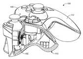
- FIG. 2is a perspective view of controller 100 , an embodiment of the present invention.
- FIG. 3is perspective view of some components of controller 100 .
- FIG. 4is a perspective view of assembly 102 that incorporates a force feedback mechanism.
- FIG. 5is an exploded view of assembly 102 .
- FIG. 6is a perspective view of thumb cap 136 in 3 positions as it is rotated about a left-right axis.
- FIG. 7is a perspective view of thumb cap 136 in 3 positions as it is rotated about a front-back axis.
- FIG. 8is a cut away view illustrating assembly 102 within the body of controller 100 .
- the current game controllers used with the various versions of the Sony PlayStation®, Microsoft Xbox® or other game systemshave multiple sets of controls in one small form factor. These controllers are held with two hands and there are typically two different independent systems to control the action for each hand.
- a usermay choose to play with whatever combination of controls he chooses.
- the controlleris ergonomically shaped so that each hand can wrap around the controller and so that triggers can be pulled with the index finger of each hand. This requires a lobe for the palm of each hand to wrap around and grip.
- wireless versions batteriesmust also be accommodated. Thus, there are space constraints not otherwise present in a stand alone joystick.
- force feedbackadds a new dimension to the experience.
- driving or other simulation type gamesthat mimic situations with real world gravitational forces that a user is familiar with will enhance the user experience.
- gravitational forces acting on a vehicle as it corners or changes velocitycan be simulated with the controller by providing resistance to the user's input at the controller.
- the force feedbackcan make the joystick easier or more difficult to move in a particular direction based upon the action taking place in the game.
- FIG. 1Ashows a prior game controller 10 that provides force feedback to directional pad 12 with a pair of electromagnetic drives 14 A and 14 B.
- the directional pad 12 and the associated electromagnetic drives 14take up a very large portion of the overall controller 10 .
- directional pad 12 and the associated electromagnetic drives 14occupy the left half of the controller while circuit board 16 occupies the right half of the controller.
- circuit board 16occupies the right half of the controller.
- Triggersare also present on the underside of the controller.
- controller 10has two sets of game controls: the directional pad 12 on the left; and the joypad buttons on the right.
- Each electromagnetic drive 14(A or B) has two electromagnetic coils 18 . As can be seen in FIG. 1B , coil 18 A is on the left and coil 18 B is on the right. Between the coils is a member that is driven based on the field generated by the coils. The member is coupled to the directional pad 12 and the force produced at the member by the coils is transmitted to pad 12 . Position sensor 22 detects the position of the member. The controller 10 utilizes a direct coupled electromagnetic drive to provide force feedback to the directional pad. By direct coupled, it is meant that the force produced at the member is coupled to the directional pad without usage of a gear system.
- FIG. 2illustrates game controller 100 , an embodiment of the present invention.
- Controller 100comprises a body 106 . Both controller 100 and body 106 are meant to be held with two hands when playing a game and comprise a left lobe 10 and right lobe 112 . A player grips each of the lobes and then can manipulate the left set of controls 104 and the right set of controls, 108 with a thumb of each hand, and can pull a trigger 130 (not shown) with another finger such as an index finger.
- Each set of controlsincludes two or more different types of controls. The various types include the aforementioned directional pad, game control buttons also referred to as a joypad, and a thumb cap/joystick.
- FIG. 3illustrates a main printed circuit board 120 of the controller.
- a first sidewhich can be referred to as the top side as it is adjacent the top of the controller, is a mini joystick 122 .
- motor 126is mounted on the opposite side of the main circuit board 120 .
- a pinion 128On a shaft of motor 126 is a pinion 128 .
- One trigger 130is also shown.
- FIG. 4is a perspective view
- FIG. 5is an exploded view of assembly 102 of controller 100 .
- Assembly 102comprises a printed circuit board, which may be the main printed circuit board 120 or any other separate or additional printed circuit board. It also comprises motor 126 , pinion 128 , double reduction gear 132 , which itself comprises an intermediate pinion 133 , annular sector gear 134 , mini joystick thumb cap 136 , and joystick gimbal/potentiometer mechanism 138 .
- sub frame 140has a shaft about which double reduction gear 132 rotates.
- Sub frame 140also has a shaft about which annular sector gear 134 pivots.
- the sub frameextends through the circuit board from the top side of the circuit board to the bottom side, where the motor 126 mounts to the sub frame.
- a cylindrical protrusion surrounding the output shaftfits within a circular hole of the sub frame.
- This assemblyallows the motor to be placed where it can best be accommodated, on the underside of the main circuit board.
- the circuit boardneed not necessarily be the main circuit board but may be an auxiliary circuit board.
- the motorextends into the lobes of the controller. In certain embodiments where a relatively large amount of torque and motor are required in comparison to the body size the body of controller 100 , the body may include a slight protrusion at the underside to accommodate the motor.
- Torque produced by the gear systemis multiplied by the combination of the various gears. This enables usage of a relatively small motor in order to produce a desired torque upon thumb cap 136 . Given that wireless embodiments of controller 100 with long battery life and play time are important, a smaller and more efficient motor is desirable. Furthermore, the smaller motor, and compact geometry of assembly 102 in general, allow for a smaller overall controller. As mentioned in the background, prior art controller 10 is rather large and heavy. This is likely a result of the rather large electromagnetic drive system. Furthermore, on a per axis basis, at 4 volts the prior art force feedback system draws 300 milliamps, whereas at the same voltage the force feedback system of assembly 102 draws only 50 milliamps.
- the force feedback system of the present inventionconsumes about one sixth the power of the prior system: about 0.2 watts vs. 1.2 watts.
- this consumption differenceis even more important. This is not only the case for wireless embodiments, but also for embodiments drawing power from a USB connection, which is specified to provide a maximum of 2.5 watts.
- the ratio of the various gears in combination with the annular sector gearallows for a very compact assembly. Both the compact gear system and the compact motor make possible a smaller and lighter controller. This is an important advantage in a very competitive market where bulky controllers are not commercially successful.
- coggingoccurs because the action of the motor produces a somewhat jerky or coarse feeling as the motor turns, which is transmitted to the user and makes the force feedback and the overall controller feel jerky or otherwise poorly actuated. This is, of course, undesirable in a game controller, and the double reduction gear system of the preferred embodiments reduces this to an un-noticeable level in addition to providing a compact and efficient solution for providing force feedback within a game controller.
- FIG. 6illustrates the movement of assembly 102 along the left-right axis.
- Intermediate pinion 133meshes with the teeth on the concave portion 135 of annular sector gear 134 .
- concave portion 135travels from one end of the sector to another.
- a full size gear of the same diameter and/or ratiowould be significantly larger and impractical for inclusion in a small controller.
- FIG. 7illustrates the movement of assembly 102 along the front-back axis. As no feedback is provided along this axis the gear system is stationary. Although single axis feedback has been illustrated in the pictured embodiments, other embodiments may include dual axis feedback.
- FIG. 8is a cut-away view of controller 100 .
- Assembly 102is shown actuating one of the controls of the left lobe 110 of the controller. This feedback may, however, be provided at the left or right side controls.
- the motoris directly under the gimbal/potentiometer mechanism 138 , in other embodiments it extends outside of the footprint towards or into the lobes.
Landscapes
- Engineering & Computer Science (AREA)
- Multimedia (AREA)
- Human Computer Interaction (AREA)
- Computer Networks & Wireless Communication (AREA)
- Mechanical Control Devices (AREA)
- Toys (AREA)
Abstract
Description
Claims (14)
Priority Applications (1)
| Application Number | Priority Date | Filing Date | Title |
|---|---|---|---|
| US11/768,244US8545323B2 (en) | 2006-06-30 | 2007-06-26 | Video game controller with compact and efficient force feedback mechanism |
Applications Claiming Priority (2)
| Application Number | Priority Date | Filing Date | Title |
|---|---|---|---|
| US80639606P | 2006-06-30 | 2006-06-30 | |
| US11/768,244US8545323B2 (en) | 2006-06-30 | 2007-06-26 | Video game controller with compact and efficient force feedback mechanism |
Publications (2)
| Publication Number | Publication Date |
|---|---|
| US20080004114A1 US20080004114A1 (en) | 2008-01-03 |
| US8545323B2true US8545323B2 (en) | 2013-10-01 |
Family
ID=38877388
Family Applications (1)
| Application Number | Title | Priority Date | Filing Date |
|---|---|---|---|
| US11/768,244Active2032-02-26US8545323B2 (en) | 2006-06-30 | 2007-06-26 | Video game controller with compact and efficient force feedback mechanism |
Country Status (1)
| Country | Link |
|---|---|
| US (1) | US8545323B2 (en) |
Cited By (49)
| Publication number | Priority date | Publication date | Assignee | Title |
|---|---|---|---|---|
| US20140274398A1 (en)* | 2013-03-15 | 2014-09-18 | Immersion Corporation | Programmable haptic peripheral |
| USD763967S1 (en)* | 2015-06-12 | 2016-08-16 | Microsoft Corporation | Thumbstick attachment for a controller |
| USD764597S1 (en)* | 2015-06-12 | 2016-08-23 | Microsoft Corporation | Thumbstick attachment for a controller |
| USD766376S1 (en)* | 2015-06-12 | 2016-09-13 | Microsoft Corporation | Controller with removable directional pad |
| USD767038S1 (en)* | 2015-06-12 | 2016-09-20 | Microsoft Corporation | Controller with removable thumbstick attachment |
| USD767684S1 (en)* | 2015-06-12 | 2016-09-27 | Microsoft Corporation | Controller with a removable directional pad |
| USD768784S1 (en)* | 2015-06-12 | 2016-10-11 | Microsoft Corporation | Controller with removable thumbstick attachment |
| USD768786S1 (en)* | 2015-08-27 | 2016-10-11 | Amazon Technologies, Inc. | Game controller |
| USD772988S1 (en)* | 2015-06-12 | 2016-11-29 | Microsoft Corporation | Controller |
| USD772987S1 (en)* | 2015-06-12 | 2016-11-29 | Microsoft Corporation | Controller |
| USD773561S1 (en)* | 2015-06-12 | 2016-12-06 | Microsoft Corporation | Controller with removable thumbstick attachment |
| USD774143S1 (en)* | 2015-06-12 | 2016-12-13 | Microsoft Corporation | Thumbstick attachment for a controller |
| USD774596S1 (en)* | 2015-06-15 | 2016-12-20 | Microsoft Corporation | Controller |
| USD777843S1 (en)* | 2015-10-29 | 2017-01-31 | Microsoft Corporation | Controller |
| USD778990S1 (en)* | 2015-10-29 | 2017-02-14 | Microsoft Corporation | Controller |
| USD784335S1 (en) | 2015-10-29 | 2017-04-18 | Microsoft Corporation | Controller with removeable paddles |
| USD784989S1 (en) | 2015-10-29 | 2017-04-25 | Microsoft Corporation | Controller |
| USD784988S1 (en) | 2015-10-29 | 2017-04-25 | Microsoft Corporation | Controller with removeable thumbstick attachment |
| USD784986S1 (en) | 2015-10-29 | 2017-04-25 | Microsoft Corporation | Thumbstick for a controller |
| USD785624S1 (en) | 2015-10-29 | 2017-05-02 | Microsoft Corporation | Battery compartment for a controller |
| USD794024S1 (en) | 2015-10-29 | 2017-08-08 | Microsoft Corporation | Directional pad for a controller |
| USD794129S1 (en) | 2016-05-13 | 2017-08-08 | Microsoft Corporation | Controller |
| USD794026S1 (en) | 2015-10-29 | 2017-08-08 | Microsoft Corporation | Set of paddles for a controller |
| USD794717S1 (en) | 2016-05-13 | 2017-08-15 | Microsoft Corporation | Controller |
| USD795351S1 (en) | 2016-06-09 | 2017-08-22 | Microsoft Corporation | Controller |
| USD795350S1 (en) | 2016-06-09 | 2017-08-22 | Microsoft Corporation | Controller |
| USD795961S1 (en) | 2016-07-14 | 2017-08-29 | Microsoft Corporation | Controller |
| USD799599S1 (en) | 2016-05-13 | 2017-10-10 | Microsoft Corporation | Controller |
| US9866149B2 (en) | 2014-07-28 | 2018-01-09 | Immersion Corporation | Method and apparatus for enabling floating touch screen haptics assemblies |
| USD816170S1 (en) | 2017-04-06 | 2018-04-24 | Microsoft Corporation | Controller |
| USD816773S1 (en) | 2017-04-06 | 2018-05-01 | Microsoft Corporation | Controller |
| USD825005S1 (en) | 2017-04-06 | 2018-08-07 | Microsoft Corporation | Controller |
| US10133354B2 (en)* | 2013-04-22 | 2018-11-20 | Immersion Corporation | Gaming device having a haptic-enabled trigger |
| US10226697B2 (en) | 2017-06-01 | 2019-03-12 | Microsoft Technology Licensing, Llc | Input device with sector geared feedback trigger |
| US10384123B2 (en) | 2017-06-01 | 2019-08-20 | Microsoft Technology Licensing, Llc | Motor-driven adjustable-tension trigger |
| USD872183S1 (en) | 2018-06-08 | 2020-01-07 | Microsoft Corporation | Controller |
| US10684639B2 (en)* | 2014-11-04 | 2020-06-16 | Alps Alpine Co., Ltd. | Operation device |
| US10737172B2 (en) | 2017-06-01 | 2020-08-11 | Microsoft Technology Licensing, Llc | Input device with force sensor feedback trigger |
| US10775891B2 (en) | 2018-04-02 | 2020-09-15 | Microsoft Technology Licensing, Llc | Resistance-based haptic device |
| US10773159B2 (en) | 2017-06-01 | 2020-09-15 | Microsoft Technology Licensing, Llc | Input device with linear geared feedback trigger |
| US10814222B2 (en) | 2018-09-21 | 2020-10-27 | Logitech Europe S.A. | Gaming controller with adaptable input configurations |
| US10850190B2 (en) | 2017-06-01 | 2020-12-01 | Microsoft Technology Licensing, Llc | Input device with clutched force-feedback trigger |
| US11214970B2 (en) | 2016-04-07 | 2022-01-04 | Schwing Gmbh | Remote control device for a large manipulator having a control lever |
| US11226685B2 (en) | 2019-06-12 | 2022-01-18 | Microsoft Technology Licensing, Llc | Haptic controller |
| US11260297B2 (en) | 2020-05-01 | 2022-03-01 | Dell Products L.P. | Information handling system wheel input device |
| US11433314B2 (en) | 2020-05-01 | 2022-09-06 | Dell Products L.P. | Information handling system hands free voice and text chat |
| US11439902B2 (en) | 2020-05-01 | 2022-09-13 | Dell Products L.P. | Information handling system gaming controls |
| US20230096068A1 (en)* | 2021-09-24 | 2023-03-30 | Apple Inc. | Rotary reluctance input device with asymmetric poles |
| US12056282B1 (en)* | 2023-07-03 | 2024-08-06 | Lemon Inc. | Adaptive triggers implementing soft actuators |
Families Citing this family (15)
| Publication number | Priority date | Publication date | Assignee | Title |
|---|---|---|---|---|
| PL2231291T3 (en)* | 2007-11-15 | 2012-03-30 | Ergowerx Llc | Motorized game controller |
| US8961313B2 (en)* | 2009-05-29 | 2015-02-24 | Sony Computer Entertainment America Llc | Multi-positional three-dimensional controller |
| US8366547B2 (en) | 2010-12-06 | 2013-02-05 | Ignite Game Technologies, Inc. | Racing car wheel and controls for use in a multimedia interactive environment |
| US8902159B1 (en) | 2012-07-24 | 2014-12-02 | John Matthews | Ergonomic support apparatus having situational sensory augmentation |
| TWM569644U (en)* | 2018-07-30 | 2018-11-11 | 正崴精密工業股份有限公司 | Game controller |
| CN110529647A (en)* | 2019-09-27 | 2019-12-03 | 余国华 | A kind of electromechanical valve actuator |
| JP7353912B2 (en)* | 2019-10-17 | 2023-10-02 | 任天堂株式会社 | Input devices, game controllers, information processing devices |
| CN111346368A (en) | 2020-02-28 | 2020-06-30 | 歌尔科技有限公司 | A game handle and its joystick feedback force device |
| CN111359202B (en) | 2020-02-28 | 2023-12-26 | 歌尔科技有限公司 | Game paddle and rocker feedback force device thereof |
| CN111437595B (en)* | 2020-04-23 | 2022-11-15 | 腾讯科技(深圳)有限公司 | Slip sensation simulator, controlled robot and gamepad |
| CN113491876B (en)* | 2021-04-28 | 2024-02-06 | 荣成歌尔科技有限公司 | Control method of analog rocker and analog rocker |
| US12121799B2 (en)* | 2022-01-13 | 2024-10-22 | Dell Products L.P. | Contextual adjustment of input device resistance |
| CN115212558A (en) | 2022-07-29 | 2022-10-21 | 瑞声开泰声学科技(上海)有限公司 | Force feedback device |
| US12251626B2 (en)* | 2023-06-16 | 2025-03-18 | Junk Food Custom Arcades, LLC. | Thumb actuated gaming controller and methods of use |
| CN117942554B (en)* | 2023-10-20 | 2024-09-20 | 深圳易速马网络科技有限公司 | Game paddle with multidirectional force feedback and control method |
Citations (56)
| Publication number | Priority date | Publication date | Assignee | Title |
|---|---|---|---|---|
| US3919691A (en) | 1971-05-26 | 1975-11-11 | Bell Telephone Labor Inc | Tactile man-machine communication system |
| US4310922A (en) | 1980-01-10 | 1982-01-12 | Lichtenberger W Wayne | Bit sampling multiplexer apparatus |
| US4398889A (en) | 1980-11-07 | 1983-08-16 | Fokker B.V. | Flight simulator |
| US4493992A (en) | 1982-08-23 | 1985-01-15 | Wico Corporation | Adapter circuit for trackball device |
| US4730188A (en) | 1984-02-15 | 1988-03-08 | Identification Devices, Inc. | Identification system |
| US4748643A (en) | 1986-03-19 | 1988-05-31 | Iwatsu Electric Co., Ltd. | Start bit detecting circuit |
| US4758164A (en) | 1985-05-03 | 1988-07-19 | Fokker B.V. | Hybrid flight simulator |
| US4823634A (en) | 1987-11-03 | 1989-04-25 | Culver Craig F | Multifunction tactile manipulatable control |
| US4868549A (en) | 1987-05-18 | 1989-09-19 | International Business Machines Corporation | Feedback mouse |
| US4894826A (en) | 1989-01-30 | 1990-01-16 | Honeywell, Inc. | Message generating communication apparatus having a message preamble format allowing parts of certain messages to be ignored |
| US4896554A (en) | 1987-11-03 | 1990-01-30 | Culver Craig F | Multifunction tactile manipulatable control |
| US4949119A (en) | 1989-01-12 | 1990-08-14 | Atari Games Corporation | Gearshift for a vehicle simulator using computer controlled realistic real world forces |
| US5043723A (en) | 1989-01-27 | 1991-08-27 | Sharp Kabushiki Kaisha | Memory remote control device |
| US5044956A (en) | 1989-01-12 | 1991-09-03 | Atari Games Corporation | Control device such as a steering wheel for video vehicle simulator with realistic feedback forces |
| US5113179A (en) | 1990-03-16 | 1992-05-12 | Advanced Gravis Computer Technology Ltd. | Switch joystick |
| NL9002669A (en) | 1990-12-05 | 1992-07-01 | Koninkl Philips Electronics Nv | DEVICE WITH A ROTATION SYMMETRICAL BODY. |
| US5197003A (en) | 1990-08-01 | 1993-03-23 | Atari Games Corporation | Gearshift for a vehicle simulator having a solenoid for imposing a resistance force |
| US5220260A (en) | 1991-10-24 | 1993-06-15 | Lex Computer And Management Corporation | Actuator having electronically controllable tactile responsiveness |
| US5264768A (en)* | 1992-10-06 | 1993-11-23 | Honeywell, Inc. | Active hand controller feedback loop |
| US5589828A (en)* | 1992-03-05 | 1996-12-31 | Armstrong; Brad A. | 6 Degrees of freedom controller with capability of tactile feedback |
| US5589854A (en) | 1995-06-22 | 1996-12-31 | Tsai; Ming-Chang | Touching feedback device |
| US5643087A (en)* | 1994-05-19 | 1997-07-01 | Microsoft Corporation | Input device including digital force feedback apparatus |
| US5691898A (en) | 1995-09-27 | 1997-11-25 | Immersion Human Interface Corp. | Safe and low cost computer peripherals with force feedback for consumer applications |
| US5721566A (en) | 1995-01-18 | 1998-02-24 | Immersion Human Interface Corp. | Method and apparatus for providing damping force feedback |
| US5739811A (en) | 1993-07-16 | 1998-04-14 | Immersion Human Interface Corporation | Method and apparatus for controlling human-computer interface systems providing force feedback |
| US5754023A (en) | 1995-10-26 | 1998-05-19 | Cybernet Systems Corporation | Gyro-stabilized platforms for force-feedback applications |
| US5831408A (en) | 1992-12-02 | 1998-11-03 | Cybernet Systems Corporation | Force feedback system |
| US5877702A (en) | 1990-03-16 | 1999-03-02 | U.S. Philips Corporation | Remote control system, start bit for biphase encoding scheme |
| US5929846A (en) | 1993-07-16 | 1999-07-27 | Immersion Corporation | Force feedback interface device including grounded sensor system |
| US5999168A (en) | 1995-09-27 | 1999-12-07 | Immersion Corporation | Haptic accelerator for force feedback computer peripherals |
| US6020875A (en) | 1997-10-31 | 2000-02-01 | Immersion Corporation | High fidelity mechanical transmission system and interface device |
| US6067077A (en) | 1998-04-10 | 2000-05-23 | Immersion Corporation | Position sensing for force feedback devices |
| US6104382A (en)* | 1997-10-31 | 2000-08-15 | Immersion Corporation | Force feedback transmission mechanisms |
| US6153843A (en)* | 1995-01-03 | 2000-11-28 | Sega Enterprises, Ltd. | Hand held control key device including multiple switch arrangements |
| US6283859B1 (en) | 1998-11-10 | 2001-09-04 | Lord Corporation | Magnetically-controllable, active haptic interface system and apparatus |
| US6292713B1 (en) | 1999-05-20 | 2001-09-18 | Compaq Computer Corporation | Robotic telepresence system |
| US6300936B1 (en) | 1997-11-14 | 2001-10-09 | Immersion Corporation | Force feedback system including multi-tasking graphical host environment and interface device |
| US6320284B1 (en) | 1998-12-23 | 2001-11-20 | Engineering Matters, Inc. | Motor assembly allowing output in multiple degrees of freedom |
| US6429849B1 (en)* | 2000-02-29 | 2002-08-06 | Microsoft Corporation | Haptic feedback joystick |
| US6437771B1 (en) | 1995-01-18 | 2002-08-20 | Immersion Corporation | Force feedback device including flexure member between actuator and user object |
| US6512509B1 (en) | 1999-03-22 | 2003-01-28 | Logitech Europe S.A. | Forked gimbal arm force feedback mechanism |
| US6536298B1 (en) | 2000-06-30 | 2003-03-25 | Caterpillar Inc | Modular joystick |
| US6573885B1 (en)* | 1999-03-22 | 2003-06-03 | Logitech Europe S.A. | Folded gear drive force feedback mechanism with direct drive sensors |
| US6613000B1 (en) | 2000-09-30 | 2003-09-02 | The Regents Of The University Of California | Method and apparatus for mass-delivered movement rehabilitation |
| US20030195042A1 (en)* | 2001-01-29 | 2003-10-16 | Microsoft Corporation | Force feedback mechanism for gamepad device |
| US6639581B1 (en) | 1995-11-17 | 2003-10-28 | Immersion Corporation | Flexure mechanism for interface device |
| US6646632B2 (en) | 2000-12-01 | 2003-11-11 | Logitech Europe S.A. | Tactile force feedback device |
| US6704001B1 (en) | 1995-11-17 | 2004-03-09 | Immersion Corporation | Force feedback device including actuator with moving magnet |
| US6710764B1 (en) | 2000-05-09 | 2004-03-23 | Logitech Europe S.A. | Method and system for processing force feedback effects generated at a host for playback at a physical interaction device |
| US6756967B2 (en) | 2000-12-22 | 2004-06-29 | Alps Electric Co., Ltd. | Manual input device improved in operatability and multifunctionality, and vehicle-mounted control device using it |
| US6801008B1 (en) | 1992-12-02 | 2004-10-05 | Immersion Corporation | Force feedback system and actuator power management |
| US20050269769A1 (en)* | 2004-06-07 | 2005-12-08 | Herschel Naghi | Handheld controller |
| US7038667B1 (en)* | 1998-10-26 | 2006-05-02 | Immersion Corporation | Mechanisms for control knobs and other interface devices |
| US20070253178A1 (en)* | 2004-07-08 | 2007-11-01 | Hidehiro Uchiumi | Fixing Holder for Vibration Generating Device |
| US20070278871A1 (en)* | 2003-09-09 | 2007-12-06 | Namiki Seimitsu Houseki Kabushiki Kaisha | Vibration Generating Motor |
| US7327348B2 (en)* | 1996-11-26 | 2008-02-05 | Immersion Corporation | Haptic feedback effects for control knobs and other interface devices |
- 2007
- 2007-06-26USUS11/768,244patent/US8545323B2/enactiveActive
Patent Citations (67)
| Publication number | Priority date | Publication date | Assignee | Title |
|---|---|---|---|---|
| US3919691A (en) | 1971-05-26 | 1975-11-11 | Bell Telephone Labor Inc | Tactile man-machine communication system |
| US4310922A (en) | 1980-01-10 | 1982-01-12 | Lichtenberger W Wayne | Bit sampling multiplexer apparatus |
| US4398889A (en) | 1980-11-07 | 1983-08-16 | Fokker B.V. | Flight simulator |
| US4493992A (en) | 1982-08-23 | 1985-01-15 | Wico Corporation | Adapter circuit for trackball device |
| US4730188A (en) | 1984-02-15 | 1988-03-08 | Identification Devices, Inc. | Identification system |
| US4758164A (en) | 1985-05-03 | 1988-07-19 | Fokker B.V. | Hybrid flight simulator |
| US4748643A (en) | 1986-03-19 | 1988-05-31 | Iwatsu Electric Co., Ltd. | Start bit detecting circuit |
| US4868549A (en) | 1987-05-18 | 1989-09-19 | International Business Machines Corporation | Feedback mouse |
| US4896554A (en) | 1987-11-03 | 1990-01-30 | Culver Craig F | Multifunction tactile manipulatable control |
| US4823634A (en) | 1987-11-03 | 1989-04-25 | Culver Craig F | Multifunction tactile manipulatable control |
| US5044956A (en) | 1989-01-12 | 1991-09-03 | Atari Games Corporation | Control device such as a steering wheel for video vehicle simulator with realistic feedback forces |
| US4949119A (en) | 1989-01-12 | 1990-08-14 | Atari Games Corporation | Gearshift for a vehicle simulator using computer controlled realistic real world forces |
| US5043723A (en) | 1989-01-27 | 1991-08-27 | Sharp Kabushiki Kaisha | Memory remote control device |
| US4894826A (en) | 1989-01-30 | 1990-01-16 | Honeywell, Inc. | Message generating communication apparatus having a message preamble format allowing parts of certain messages to be ignored |
| US5113179A (en) | 1990-03-16 | 1992-05-12 | Advanced Gravis Computer Technology Ltd. | Switch joystick |
| US5877702A (en) | 1990-03-16 | 1999-03-02 | U.S. Philips Corporation | Remote control system, start bit for biphase encoding scheme |
| US5197003A (en) | 1990-08-01 | 1993-03-23 | Atari Games Corporation | Gearshift for a vehicle simulator having a solenoid for imposing a resistance force |
| NL9002669A (en) | 1990-12-05 | 1992-07-01 | Koninkl Philips Electronics Nv | DEVICE WITH A ROTATION SYMMETRICAL BODY. |
| USRE38242E1 (en) | 1990-12-05 | 2003-09-02 | Koninklijke Philips Electronics N.V. | Force feedback apparatus and method |
| US5781172A (en) | 1990-12-05 | 1998-07-14 | U.S. Philips Corporation | Data input device for use with a data processing apparatus and a data processing apparatus provided with such a device |
| US5220260A (en) | 1991-10-24 | 1993-06-15 | Lex Computer And Management Corporation | Actuator having electronically controllable tactile responsiveness |
| US5589828A (en)* | 1992-03-05 | 1996-12-31 | Armstrong; Brad A. | 6 Degrees of freedom controller with capability of tactile feedback |
| US5264768A (en)* | 1992-10-06 | 1993-11-23 | Honeywell, Inc. | Active hand controller feedback loop |
| US6801008B1 (en) | 1992-12-02 | 2004-10-05 | Immersion Corporation | Force feedback system and actuator power management |
| US5831408A (en) | 1992-12-02 | 1998-11-03 | Cybernet Systems Corporation | Force feedback system |
| US6104158A (en) | 1992-12-02 | 2000-08-15 | Immersion Corporation | Force feedback system |
| US6300937B1 (en) | 1993-07-16 | 2001-10-09 | Immersion Corporation | Method and apparatus for controlling force feedback for a computer interface device |
| US5739811A (en) | 1993-07-16 | 1998-04-14 | Immersion Human Interface Corporation | Method and apparatus for controlling human-computer interface systems providing force feedback |
| US5929846A (en) | 1993-07-16 | 1999-07-27 | Immersion Corporation | Force feedback interface device including grounded sensor system |
| US5643087A (en)* | 1994-05-19 | 1997-07-01 | Microsoft Corporation | Input device including digital force feedback apparatus |
| US6153843A (en)* | 1995-01-03 | 2000-11-28 | Sega Enterprises, Ltd. | Hand held control key device including multiple switch arrangements |
| US6437771B1 (en) | 1995-01-18 | 2002-08-20 | Immersion Corporation | Force feedback device including flexure member between actuator and user object |
| US5721566A (en) | 1995-01-18 | 1998-02-24 | Immersion Human Interface Corp. | Method and apparatus for providing damping force feedback |
| US6271828B1 (en) | 1995-01-18 | 2001-08-07 | Immersion Corporation | Force feedback interface devices providing resistance forces using a fluid |
| US6201533B1 (en)* | 1995-01-18 | 2001-03-13 | Immersion Corporation | Method and apparatus for applying force in force feedback devices using friction |
| US5589854A (en) | 1995-06-22 | 1996-12-31 | Tsai; Ming-Chang | Touching feedback device |
| US5999168A (en) | 1995-09-27 | 1999-12-07 | Immersion Corporation | Haptic accelerator for force feedback computer peripherals |
| US5929607A (en) | 1995-09-27 | 1999-07-27 | Immersion Corporation | Low cost force feedback interface with efficient power sourcing |
| US5691898A (en) | 1995-09-27 | 1997-11-25 | Immersion Human Interface Corp. | Safe and low cost computer peripherals with force feedback for consumer applications |
| US5907487A (en) | 1995-09-27 | 1999-05-25 | Immersion Corporation | Force feedback device with safety feature |
| US6348911B1 (en) | 1995-09-27 | 2002-02-19 | Immersion Corporation | Force feedback device including safety switch and force magnitude ramping |
| US5754023A (en) | 1995-10-26 | 1998-05-19 | Cybernet Systems Corporation | Gyro-stabilized platforms for force-feedback applications |
| USRE37374E1 (en) | 1995-10-26 | 2001-09-18 | Cybernet Haptic Systems Corporation | Gyro-stabilized platforms for force-feedback applications |
| US6704001B1 (en) | 1995-11-17 | 2004-03-09 | Immersion Corporation | Force feedback device including actuator with moving magnet |
| US6639581B1 (en) | 1995-11-17 | 2003-10-28 | Immersion Corporation | Flexure mechanism for interface device |
| US7327348B2 (en)* | 1996-11-26 | 2008-02-05 | Immersion Corporation | Haptic feedback effects for control knobs and other interface devices |
| US6020875A (en) | 1997-10-31 | 2000-02-01 | Immersion Corporation | High fidelity mechanical transmission system and interface device |
| US6380925B1 (en) | 1997-10-31 | 2002-04-30 | Immersion Corporation | Force feedback device with spring selection mechanism |
| US6104382A (en)* | 1997-10-31 | 2000-08-15 | Immersion Corporation | Force feedback transmission mechanisms |
| US6300936B1 (en) | 1997-11-14 | 2001-10-09 | Immersion Corporation | Force feedback system including multi-tasking graphical host environment and interface device |
| US6067077A (en) | 1998-04-10 | 2000-05-23 | Immersion Corporation | Position sensing for force feedback devices |
| US7038667B1 (en)* | 1998-10-26 | 2006-05-02 | Immersion Corporation | Mechanisms for control knobs and other interface devices |
| US6283859B1 (en) | 1998-11-10 | 2001-09-04 | Lord Corporation | Magnetically-controllable, active haptic interface system and apparatus |
| US6320284B1 (en) | 1998-12-23 | 2001-11-20 | Engineering Matters, Inc. | Motor assembly allowing output in multiple degrees of freedom |
| US6512509B1 (en) | 1999-03-22 | 2003-01-28 | Logitech Europe S.A. | Forked gimbal arm force feedback mechanism |
| US6573885B1 (en)* | 1999-03-22 | 2003-06-03 | Logitech Europe S.A. | Folded gear drive force feedback mechanism with direct drive sensors |
| US6292713B1 (en) | 1999-05-20 | 2001-09-18 | Compaq Computer Corporation | Robotic telepresence system |
| US6429849B1 (en)* | 2000-02-29 | 2002-08-06 | Microsoft Corporation | Haptic feedback joystick |
| US6710764B1 (en) | 2000-05-09 | 2004-03-23 | Logitech Europe S.A. | Method and system for processing force feedback effects generated at a host for playback at a physical interaction device |
| US6536298B1 (en) | 2000-06-30 | 2003-03-25 | Caterpillar Inc | Modular joystick |
| US6613000B1 (en) | 2000-09-30 | 2003-09-02 | The Regents Of The University Of California | Method and apparatus for mass-delivered movement rehabilitation |
| US6646632B2 (en) | 2000-12-01 | 2003-11-11 | Logitech Europe S.A. | Tactile force feedback device |
| US6756967B2 (en) | 2000-12-22 | 2004-06-29 | Alps Electric Co., Ltd. | Manual input device improved in operatability and multifunctionality, and vehicle-mounted control device using it |
| US20030195042A1 (en)* | 2001-01-29 | 2003-10-16 | Microsoft Corporation | Force feedback mechanism for gamepad device |
| US20070278871A1 (en)* | 2003-09-09 | 2007-12-06 | Namiki Seimitsu Houseki Kabushiki Kaisha | Vibration Generating Motor |
| US20050269769A1 (en)* | 2004-06-07 | 2005-12-08 | Herschel Naghi | Handheld controller |
| US20070253178A1 (en)* | 2004-07-08 | 2007-11-01 | Hidehiro Uchiumi | Fixing Holder for Vibration Generating Device |
Non-Patent Citations (21)
| Title |
|---|
| "Automotive Steering Control Loader", McFadden Systems, Inc., product brochure, Interservice/Industry Training Systems Conference, Nov. 29, 30, Dec. 1, 2, 1987, 2 pages. |
| "Hard Drivin'", game promotional flyer, Atari Games Corporation, 1989, 2 pages. |
| E. Donges, "Via Automobile Driving Simulator for Anthropogenic Research", published as report No. FB-41, Jul. 1978, pp. 1-44 (plus English abstract). |
| Gravis Destroyer Tilt Review, Hardware Review, http://www.sharkygames.com/hardware/reviews/controller/gravis-destoyer-tilt/2.shtml, downloaded Mar. 9, 2006, 2 pages. |
| Gravis Exterminator Controller Picture, http://images.amazon.com/images/P/B00004R8U2.01.LZZZZZZZ.jpg, downloaded Mar. 9, 2006, 1 page. |
| Instech, Motor Speed Control Cards, Feb. 5, 2004, http://www.instechlabs.com/OEM/controlcards/.* |
| Legion Hardware, Eliminator AfterShock Review, http://www.legionhardware.com/document.php?id=32&p=1, Dec. 20, 2001, 3 pages. |
| Logitech, "Tiger Wingman Formula Force Wheel Hardware Specifications," SPEC-HW, ENG SPEC, TIGER, HWS-761782-0000, Rev. A, Mar. 9, 1999, 28 pages. |
| Logitech, "Wingman Formula Force", product brochure, 1998, 2 pages. |
| Logitech® Force(TM) 3D Pro, product listing, http://www.logitech.com/index.cfm/products/details/US/EN,CRID=2221,CONTENTID=10714, downloaded Sep. 23, 2005, 3 pages. |
| Logitech® Force(TM) 3D, product listing, http://www.logitech.com/index.cfin/products/details/US/EN,CRID=2221,CONTENTID=5016, downloaded Sep. 23, 2005, 2 pages. |
| Logitech® Force™ 3D Pro, product listing, http://www.logitech.com/index.cfm/products/details/US/EN,CRID=2221,CONTENTID=10714, downloaded Sep. 23, 2005, 3 pages. |
| Logitech® Force™ 3D, product listing, http://www.logitech.com/index.cfin/products/details/US/EN,CRID=2221,CONTENTID=5016, downloaded Sep. 23, 2005, 2 pages. |
| Logitech® Formula(TM) Force GP, product listing, http://www.logitech.com/index.cfm/products/details/US/EN,CRID=2217,CONTENTID=5026, downloaded Sep. 23, 2005, 2 pages. |
| Logitech® Formula™ Force GP, product listing, http://www.logitech.com/index.cfm/products/details/US/EN,CRID=2217,CONTENTID=5026, downloaded Sep. 23, 2005, 2 pages. |
| Logitech® MOMO® Racing, product listing, http://www.logitech.com/index.cfm/products/details/US/EN,CRID=2217,CONTENTID=6030, downloaded Sep. 23, 2005, 2 pages. |
| Logitech® NASCAR® Racing Wheel, product listing, http://www.logitech.com/index.cfm/products/details/US/EN,CRID=2217,CONTENTID=9489, downloaded Sep. 23, 2005, 4 pages. |
| Logitech® Precision(TM) Controller for Xbox®, product listing, http://www.logitec.com/index.cfm/products/details/US/EN,CRID= . . . , downloaded Oct. 5, 2005, 3 pages. |
| Logitech® Precision™ Controller for Xbox®, product listing, http://www.logitec.com/index.cfm/products/details/US/EN,CRID= . . . , downloaded Oct. 5, 2005, 3 pages. |
| Margaret Minsky et al., "Feeling and Seeing: Issues in Force Display", Proceedings 1990 Symposium on Interactive 3D Graphics, Snowbird, Utah, Mar. 25-28, 1990, 11 pages. |
| Repperger et al., U.S. Statutory Invention Registration No. H703, "Manual Control Apparatus With Electable Mechanical Impedance," published on Nov. 7, 1989. |
Cited By (57)
| Publication number | Priority date | Publication date | Assignee | Title |
|---|---|---|---|---|
| US20140274398A1 (en)* | 2013-03-15 | 2014-09-18 | Immersion Corporation | Programmable haptic peripheral |
| US10279251B2 (en) | 2013-03-15 | 2019-05-07 | Immersion Corporation | Programmable haptic peripheral |
| US10124252B2 (en)* | 2013-03-15 | 2018-11-13 | Immersion Corporation | Programmable haptic peripheral |
| US9557830B2 (en)* | 2013-03-15 | 2017-01-31 | Immersion Corporation | Programmable haptic peripheral |
| US10133354B2 (en)* | 2013-04-22 | 2018-11-20 | Immersion Corporation | Gaming device having a haptic-enabled trigger |
| US9866149B2 (en) | 2014-07-28 | 2018-01-09 | Immersion Corporation | Method and apparatus for enabling floating touch screen haptics assemblies |
| US10684639B2 (en)* | 2014-11-04 | 2020-06-16 | Alps Alpine Co., Ltd. | Operation device |
| USD772988S1 (en)* | 2015-06-12 | 2016-11-29 | Microsoft Corporation | Controller |
| USD772987S1 (en)* | 2015-06-12 | 2016-11-29 | Microsoft Corporation | Controller |
| USD773561S1 (en)* | 2015-06-12 | 2016-12-06 | Microsoft Corporation | Controller with removable thumbstick attachment |
| USD774143S1 (en)* | 2015-06-12 | 2016-12-13 | Microsoft Corporation | Thumbstick attachment for a controller |
| USD768784S1 (en)* | 2015-06-12 | 2016-10-11 | Microsoft Corporation | Controller with removable thumbstick attachment |
| USD767684S1 (en)* | 2015-06-12 | 2016-09-27 | Microsoft Corporation | Controller with a removable directional pad |
| USD767038S1 (en)* | 2015-06-12 | 2016-09-20 | Microsoft Corporation | Controller with removable thumbstick attachment |
| USD766376S1 (en)* | 2015-06-12 | 2016-09-13 | Microsoft Corporation | Controller with removable directional pad |
| USD764597S1 (en)* | 2015-06-12 | 2016-08-23 | Microsoft Corporation | Thumbstick attachment for a controller |
| USD763967S1 (en)* | 2015-06-12 | 2016-08-16 | Microsoft Corporation | Thumbstick attachment for a controller |
| USD774596S1 (en)* | 2015-06-15 | 2016-12-20 | Microsoft Corporation | Controller |
| USD768786S1 (en)* | 2015-08-27 | 2016-10-11 | Amazon Technologies, Inc. | Game controller |
| USD784335S1 (en) | 2015-10-29 | 2017-04-18 | Microsoft Corporation | Controller with removeable paddles |
| USD784988S1 (en) | 2015-10-29 | 2017-04-25 | Microsoft Corporation | Controller with removeable thumbstick attachment |
| USD794024S1 (en) | 2015-10-29 | 2017-08-08 | Microsoft Corporation | Directional pad for a controller |
| USD777843S1 (en)* | 2015-10-29 | 2017-01-31 | Microsoft Corporation | Controller |
| USD794026S1 (en) | 2015-10-29 | 2017-08-08 | Microsoft Corporation | Set of paddles for a controller |
| USD778990S1 (en)* | 2015-10-29 | 2017-02-14 | Microsoft Corporation | Controller |
| USD784989S1 (en) | 2015-10-29 | 2017-04-25 | Microsoft Corporation | Controller |
| USD785624S1 (en) | 2015-10-29 | 2017-05-02 | Microsoft Corporation | Battery compartment for a controller |
| USD784986S1 (en) | 2015-10-29 | 2017-04-25 | Microsoft Corporation | Thumbstick for a controller |
| US11214970B2 (en) | 2016-04-07 | 2022-01-04 | Schwing Gmbh | Remote control device for a large manipulator having a control lever |
| USD799599S1 (en) | 2016-05-13 | 2017-10-10 | Microsoft Corporation | Controller |
| USD794717S1 (en) | 2016-05-13 | 2017-08-15 | Microsoft Corporation | Controller |
| USD794129S1 (en) | 2016-05-13 | 2017-08-08 | Microsoft Corporation | Controller |
| USD795350S1 (en) | 2016-06-09 | 2017-08-22 | Microsoft Corporation | Controller |
| USD795351S1 (en) | 2016-06-09 | 2017-08-22 | Microsoft Corporation | Controller |
| USD795960S1 (en) | 2016-07-14 | 2017-08-29 | Microsoft Corporation | Controller |
| USD798954S1 (en) | 2016-07-14 | 2017-10-03 | Microsoft Corporation | Controller |
| USD795961S1 (en) | 2016-07-14 | 2017-08-29 | Microsoft Corporation | Controller |
| USD799600S1 (en) | 2016-07-14 | 2017-10-10 | Microsoft Corporation | Controller |
| USD816773S1 (en) | 2017-04-06 | 2018-05-01 | Microsoft Corporation | Controller |
| USD816170S1 (en) | 2017-04-06 | 2018-04-24 | Microsoft Corporation | Controller |
| USD825005S1 (en) | 2017-04-06 | 2018-08-07 | Microsoft Corporation | Controller |
| US10773159B2 (en) | 2017-06-01 | 2020-09-15 | Microsoft Technology Licensing, Llc | Input device with linear geared feedback trigger |
| US10226697B2 (en) | 2017-06-01 | 2019-03-12 | Microsoft Technology Licensing, Llc | Input device with sector geared feedback trigger |
| US10737172B2 (en) | 2017-06-01 | 2020-08-11 | Microsoft Technology Licensing, Llc | Input device with force sensor feedback trigger |
| US10850190B2 (en) | 2017-06-01 | 2020-12-01 | Microsoft Technology Licensing, Llc | Input device with clutched force-feedback trigger |
| US10384123B2 (en) | 2017-06-01 | 2019-08-20 | Microsoft Technology Licensing, Llc | Motor-driven adjustable-tension trigger |
| US10775891B2 (en) | 2018-04-02 | 2020-09-15 | Microsoft Technology Licensing, Llc | Resistance-based haptic device |
| USD872183S1 (en) | 2018-06-08 | 2020-01-07 | Microsoft Corporation | Controller |
| US10814222B2 (en) | 2018-09-21 | 2020-10-27 | Logitech Europe S.A. | Gaming controller with adaptable input configurations |
| US11226685B2 (en) | 2019-06-12 | 2022-01-18 | Microsoft Technology Licensing, Llc | Haptic controller |
| US11260297B2 (en) | 2020-05-01 | 2022-03-01 | Dell Products L.P. | Information handling system wheel input device |
| US11433314B2 (en) | 2020-05-01 | 2022-09-06 | Dell Products L.P. | Information handling system hands free voice and text chat |
| US11439902B2 (en) | 2020-05-01 | 2022-09-13 | Dell Products L.P. | Information handling system gaming controls |
| US11731046B2 (en) | 2020-05-01 | 2023-08-22 | Dell Products L.P. | Information handling system wheel input device |
| US20230096068A1 (en)* | 2021-09-24 | 2023-03-30 | Apple Inc. | Rotary reluctance input device with asymmetric poles |
| US12265654B2 (en)* | 2021-09-24 | 2025-04-01 | Apple Inc. | Rotary reluctance input device with asymmetric poles |
| US12056282B1 (en)* | 2023-07-03 | 2024-08-06 | Lemon Inc. | Adaptive triggers implementing soft actuators |
Also Published As
| Publication number | Publication date |
|---|---|
| US20080004114A1 (en) | 2008-01-03 |
Similar Documents
| Publication | Publication Date | Title |
|---|---|---|
| US8545323B2 (en) | Video game controller with compact and efficient force feedback mechanism | |
| US6824468B2 (en) | Force feedback mechanism for gamepad device | |
| US10133354B2 (en) | Gaming device having a haptic-enabled trigger | |
| KR100501145B1 (en) | Manipulation controller and electronic device using the same | |
| US9501084B1 (en) | Wearable electronic device with force feedback | |
| CN1132646C (en) | Operating device for game machine | |
| US6686901B2 (en) | Enhancing inertial tactile feedback in computer interface devices having increased mass | |
| US20070066394A1 (en) | Video game system with wireless modular handheld controller | |
| US20110306423A1 (en) | Multi purpose wireless game control console | |
| US20030127863A1 (en) | Resistance force generator for use in a game machine | |
| KR100864613B1 (en) | Mini wheel for game consoles and game machines equipped with them | |
| CN100468294C (en) | Directional Haptic Feedback for Haptic Feedback Interface Devices | |
| US20110281651A1 (en) | Angling joystick and gaming device having same | |
| CN115253199A (en) | A kind of game-based upper limb rehabilitation training auxiliary equipment and realization method | |
| US20010004608A1 (en) | Desktop tremor joystick | |
| Caswell | Design, characterization, and testing of skin-stretch feedback integrated into a game controller | |
| JP2009112407A (en) | Electronic game control device | |
| CN102637083A (en) | An interactive system and an inertial sensing input control device for the interactive system |
Legal Events
| Date | Code | Title | Description |
|---|---|---|---|
| AS | Assignment | Owner name:LOGITECH EUROPE S.A., SWITZERLAND Free format text:ASSIGNMENT OF ASSIGNORS INTEREST;ASSIGNORS:MCVICAR, DAVID NEIL;PRATHER, VANCE ALAN;WEGMULLER, DAVID ERNEST;REEL/FRAME:019614/0817;SIGNING DATES FROM 20070620 TO 20070621 Owner name:LOGITECH EUROPE S.A., SWITZERLAND Free format text:ASSIGNMENT OF ASSIGNORS INTEREST;ASSIGNORS:MCVICAR, DAVID NEIL;PRATHER, VANCE ALAN;WEGMULLER, DAVID ERNEST;SIGNING DATES FROM 20070620 TO 20070621;REEL/FRAME:019614/0817 | |
| STCF | Information on status: patent grant | Free format text:PATENTED CASE | |
| FPAY | Fee payment | Year of fee payment:4 | |
| MAFP | Maintenance fee payment | Free format text:PAYMENT OF MAINTENANCE FEE, 8TH YEAR, LARGE ENTITY (ORIGINAL EVENT CODE: M1552); ENTITY STATUS OF PATENT OWNER: LARGE ENTITY Year of fee payment:8 | |
| FEPP | Fee payment procedure | Free format text:MAINTENANCE FEE REMINDER MAILED (ORIGINAL EVENT CODE: REM.); ENTITY STATUS OF PATENT OWNER: LARGE ENTITY |