US8545084B2 - Light guides and backlight systems incorporating light redirectors at varying densities - Google Patents
Light guides and backlight systems incorporating light redirectors at varying densitiesDownload PDFInfo
- Publication number
- US8545084B2 US8545084B2US13/570,840US201213570840AUS8545084B2US 8545084 B2US8545084 B2US 8545084B2US 201213570840 AUS201213570840 AUS 201213570840AUS 8545084 B2US8545084 B2US 8545084B2
- Authority
- US
- United States
- Prior art keywords
- light
- redirectors
- geometric
- light guide
- deflectors
- Prior art date
- Legal status (The legal status is an assumption and is not a legal conclusion. Google has not performed a legal analysis and makes no representation as to the accuracy of the status listed.)
- Expired - Fee Related
Links
- 230000007423decreaseEffects0.000claimsdescription6
- 238000000034methodMethods0.000claimsdescription4
- 238000004519manufacturing processMethods0.000claims1
- 230000000007visual effectEffects0.000abstractdescription3
- 239000002184metalSubstances0.000description14
- 238000005286illuminationMethods0.000description6
- 230000009977dual effectEffects0.000description4
- 238000010348incorporationMethods0.000description3
- 238000007373indentationMethods0.000description3
- 230000001788irregularEffects0.000description3
- 230000009897systematic effectEffects0.000description3
- 239000010409thin filmSubstances0.000description3
- 238000013461designMethods0.000description2
- 238000000605extractionMethods0.000description2
- 239000000463materialSubstances0.000description2
- 230000003287optical effectEffects0.000description2
- 239000003973paintSubstances0.000description2
- 238000002310reflectometryMethods0.000description2
- 125000006850spacer groupChemical group0.000description2
- 239000013598vectorSubstances0.000description2
- 238000007792additionMethods0.000description1
- 239000012141concentrateSubstances0.000description1
- 230000003247decreasing effectEffects0.000description1
- 230000008021depositionEffects0.000description1
- 239000010408filmSubstances0.000description1
- 239000004973liquid crystal related substanceSubstances0.000description1
- 238000012986modificationMethods0.000description1
- 230000004048modificationEffects0.000description1
- 238000012856packingMethods0.000description1
- 230000005855radiationEffects0.000description1
- 230000003252repetitive effectEffects0.000description1
- 239000012780transparent materialSubstances0.000description1
Images


Classifications
- G—PHYSICS
- G02—OPTICS
- G02B—OPTICAL ELEMENTS, SYSTEMS OR APPARATUS
- G02B6/00—Light guides; Structural details of arrangements comprising light guides and other optical elements, e.g. couplings
- G02B6/0001—Light guides; Structural details of arrangements comprising light guides and other optical elements, e.g. couplings specially adapted for lighting devices or systems
- G02B6/0011—Light guides; Structural details of arrangements comprising light guides and other optical elements, e.g. couplings specially adapted for lighting devices or systems the light guides being planar or of plate-like form
- G02B6/0033—Means for improving the coupling-out of light from the light guide
- G02B6/0035—Means for improving the coupling-out of light from the light guide provided on the surface of the light guide or in the bulk of it
- G02B6/0036—2-D arrangement of prisms, protrusions, indentations or roughened surfaces
- G—PHYSICS
- G02—OPTICS
- G02B—OPTICAL ELEMENTS, SYSTEMS OR APPARATUS
- G02B6/00—Light guides; Structural details of arrangements comprising light guides and other optical elements, e.g. couplings
- G02B6/0001—Light guides; Structural details of arrangements comprising light guides and other optical elements, e.g. couplings specially adapted for lighting devices or systems
- G02B6/0011—Light guides; Structural details of arrangements comprising light guides and other optical elements, e.g. couplings specially adapted for lighting devices or systems the light guides being planar or of plate-like form
- G02B6/0013—Means for improving the coupling-in of light from the light source into the light guide
- G02B6/0015—Means for improving the coupling-in of light from the light source into the light guide provided on the surface of the light guide or in the bulk of it
- G02B6/0018—Redirecting means on the surface of the light guide
- G—PHYSICS
- G02—OPTICS
- G02B—OPTICAL ELEMENTS, SYSTEMS OR APPARATUS
- G02B6/00—Light guides; Structural details of arrangements comprising light guides and other optical elements, e.g. couplings
- G02B6/0001—Light guides; Structural details of arrangements comprising light guides and other optical elements, e.g. couplings specially adapted for lighting devices or systems
- G02B6/0011—Light guides; Structural details of arrangements comprising light guides and other optical elements, e.g. couplings specially adapted for lighting devices or systems the light guides being planar or of plate-like form
- G02B6/0033—Means for improving the coupling-out of light from the light guide
- G02B6/0035—Means for improving the coupling-out of light from the light guide provided on the surface of the light guide or in the bulk of it
- G02B6/0038—Linear indentations or grooves, e.g. arc-shaped grooves or meandering grooves, extending over the full length or width of the light guide
- G—PHYSICS
- G02—OPTICS
- G02B—OPTICAL ELEMENTS, SYSTEMS OR APPARATUS
- G02B6/00—Light guides; Structural details of arrangements comprising light guides and other optical elements, e.g. couplings
- G02B6/0001—Light guides; Structural details of arrangements comprising light guides and other optical elements, e.g. couplings specially adapted for lighting devices or systems
- G02B6/0011—Light guides; Structural details of arrangements comprising light guides and other optical elements, e.g. couplings specially adapted for lighting devices or systems the light guides being planar or of plate-like form
- G02B6/0033—Means for improving the coupling-out of light from the light guide
- G02B6/005—Means for improving the coupling-out of light from the light guide provided by one optical element, or plurality thereof, placed on the light output side of the light guide
- G02B6/0055—Reflecting element, sheet or layer
- G—PHYSICS
- G02—OPTICS
- G02B—OPTICAL ELEMENTS, SYSTEMS OR APPARATUS
- G02B6/00—Light guides; Structural details of arrangements comprising light guides and other optical elements, e.g. couplings
- G02B6/0001—Light guides; Structural details of arrangements comprising light guides and other optical elements, e.g. couplings specially adapted for lighting devices or systems
- G02B6/0011—Light guides; Structural details of arrangements comprising light guides and other optical elements, e.g. couplings specially adapted for lighting devices or systems the light guides being planar or of plate-like form
- G02B6/0033—Means for improving the coupling-out of light from the light guide
- G02B6/0058—Means for improving the coupling-out of light from the light guide varying in density, size, shape or depth along the light guide
- G02B6/0061—Means for improving the coupling-out of light from the light guide varying in density, size, shape or depth along the light guide to provide homogeneous light output intensity
- G—PHYSICS
- G02—OPTICS
- G02B—OPTICAL ELEMENTS, SYSTEMS OR APPARATUS
- G02B6/00—Light guides; Structural details of arrangements comprising light guides and other optical elements, e.g. couplings
- G02B6/0001—Light guides; Structural details of arrangements comprising light guides and other optical elements, e.g. couplings specially adapted for lighting devices or systems
- G02B6/0011—Light guides; Structural details of arrangements comprising light guides and other optical elements, e.g. couplings specially adapted for lighting devices or systems the light guides being planar or of plate-like form
- G02B6/0065—Manufacturing aspects; Material aspects
- G—PHYSICS
- G02—OPTICS
- G02B—OPTICAL ELEMENTS, SYSTEMS OR APPARATUS
- G02B6/00—Light guides; Structural details of arrangements comprising light guides and other optical elements, e.g. couplings
- G02B6/0001—Light guides; Structural details of arrangements comprising light guides and other optical elements, e.g. couplings specially adapted for lighting devices or systems
- G02B6/0011—Light guides; Structural details of arrangements comprising light guides and other optical elements, e.g. couplings specially adapted for lighting devices or systems the light guides being planar or of plate-like form
- G02B6/0066—Light guides; Structural details of arrangements comprising light guides and other optical elements, e.g. couplings specially adapted for lighting devices or systems the light guides being planar or of plate-like form characterised by the light source being coupled to the light guide
- G02B6/0068—Arrangements of plural sources, e.g. multi-colour light sources
- G—PHYSICS
- G02—OPTICS
- G02B—OPTICAL ELEMENTS, SYSTEMS OR APPARATUS
- G02B6/00—Light guides; Structural details of arrangements comprising light guides and other optical elements, e.g. couplings
- G02B6/0001—Light guides; Structural details of arrangements comprising light guides and other optical elements, e.g. couplings specially adapted for lighting devices or systems
- G02B6/0011—Light guides; Structural details of arrangements comprising light guides and other optical elements, e.g. couplings specially adapted for lighting devices or systems the light guides being planar or of plate-like form
- G02B6/0013—Means for improving the coupling-in of light from the light source into the light guide
- G02B6/0015—Means for improving the coupling-in of light from the light source into the light guide provided on the surface of the light guide or in the bulk of it
- G02B6/002—Means for improving the coupling-in of light from the light source into the light guide provided on the surface of the light guide or in the bulk of it by shaping at least a portion of the light guide, e.g. with collimating, focussing or diverging surfaces
- G02B6/0021—Means for improving the coupling-in of light from the light source into the light guide provided on the surface of the light guide or in the bulk of it by shaping at least a portion of the light guide, e.g. with collimating, focussing or diverging surfaces for housing at least a part of the light source, e.g. by forming holes or recesses
- Y—GENERAL TAGGING OF NEW TECHNOLOGICAL DEVELOPMENTS; GENERAL TAGGING OF CROSS-SECTIONAL TECHNOLOGIES SPANNING OVER SEVERAL SECTIONS OF THE IPC; TECHNICAL SUBJECTS COVERED BY FORMER USPC CROSS-REFERENCE ART COLLECTIONS [XRACs] AND DIGESTS
- Y10—TECHNICAL SUBJECTS COVERED BY FORMER USPC
- Y10T—TECHNICAL SUBJECTS COVERED BY FORMER US CLASSIFICATION
- Y10T29/00—Metal working
- Y10T29/49—Method of mechanical manufacture
Definitions
- the displays of many portable devicesrely on backlights to provide their illumination. Viewers of these displays desire uniform light emission across the surface of a display with as few visual artifacts as possible. As screens become larger, multiple spatially separated light sources are used to illuminate the backlight. Such illumination schemes increase the challenge of providing artifact free, uniform light emission from a display.
- the inventionrelates to a light guide of display.
- the light guideincludes a front surface, a rear surface, and at least one edge separating the front and rear surfaces.
- the light guideincludes a first light introduction position on an edge of the light guide through which a light source introduces light into the light guide.
- the light guidealso has a second light introduction position, either on the same or on a different edge, through which a second light source introduces light into the light guide.
- the first light introduction positionis spatially separated from the second light introduction position.
- the light guidealso includes a plurality of geometric light redirectors, also referred to herein as deflectors.
- the light redirectorsmay have triangular, trapezoidal, trapezial, cylindrical, rounded, or other defined geometric cross section. In one implementation, at least some of the light redirectors have dimensions that are smaller than 500 microns.
- the light redirectorsare distributed amongst three regions of either the front or rear surfaces of the light guide. A first region includes light redirectors predominantly, if not solely, from a first group of light redirectors. The second region includes light redirectors predominantly, if not solely from a second group of light redirectors. The third region includes light redirectors from both groups.
- Light redirectors in the first groupsubstantially face the first light introduction position. That is, a front face of a light redirector in the first group is substantially perpendicular (e.g., within plus or minus 20 degrees of perpendicular) to a line connecting the light redirector, for example from the center of its front face, to the first light introduction position.
- Light redirectors in the second groupsimilarly substantially face the second light introduction position.
- the light redirectors in each groupmay vary in size, shape, and angle relative to the line connecting the light redirector to its corresponding light introduction position. The light redirectors may increase in height with distance from the corresponding light introduction position.
- the light guidealso includes a plurality of light sources. At least one light source is associated with each light introduction position.
- the light sourcemight be white or colored.
- a single light sourcemay include multiple colored lamps.
- the lampsmay be, for example, light emitting diodes.
- the inventionin another aspect, relates to a light guide of a display that includes a plurality of geometric light redirectors that face a light introduction position on an edge of the light guide.
- the density of the plurality of light redirectorsbeginning at a first distance along a direction radially extending from the light introduction position, gradually decreases as the distance increases.
- the light redirectorsmay increase in height with in relation to their respective distances from the light introduction position.
- the densitymay decrease substantially continuously or in a step wise fashion.
- the direction in which the density of the light redirectors gradually decreasesis at least partially towards a second light introduction position on an edge of the light guide.
- the inventionin another aspect, relates to a light guide of a display having a front surface, a rear surface, and first, second, and third edges separating the front and rear surfaces.
- Distributed across one of the front surface and the rear surfaceare a plurality of first geometric light redirectors, each having a front face substantially perpendicular to a line connecting the front face to a light introduction position on the first edge, and a plurality of second geometric light redirectors, each having a front face oriented at least partially towards the second edge or third edge.
- the light redirectorsmay increase in height with in relation to their respective distances from the light introduction position. Reflective surfaces directed towards an interior of the light guide are positioned proximate the second and third edges and.
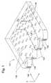
- FIG. 1is a perspective view of a first backlight system, according to an illustrative embodiment of the invention.
- FIG. 2is a perspective view of a second backlight system, according to an illustrative embodiment of the invention.
- FIG. 3is a perspective view of a third backlight system, according to an illustrative embodiment of the invention.
- FIG. 4is a top view of a fourth backlight system, according to an illustrative embodiment of the invention.
- FIG. 5is a top view of a fifth backlight system, according to an illustrative embodiment of the invention.
- FIG. 6Ais a top view of a sixth backlight system, according to an illustrative embodiment of the invention.
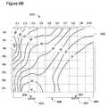
- FIG. 6Bis a density contour map indicating the density of one of two populations of light redirectors in the sixth backlight system, according to an illustrative embodiment of the invention.
- FIG. 7is a top view of a sixth backlight system, according to an illustrative embodiment of the invention.
- FIG. 8is a top view of a seventh backlight system, according to an illustrative embodiment of the invention.
- backlights and backlight systemsfor providing illumination for a display.
- backlights and backlight systems described hereinmay be adapted and modified as is appropriate for the application being addressed and that the systems and methods described herein may be employed in other suitable applications, and that such other additions and modifications will not depart from the scope hereof.
- FIG. 1illustrates a backlight system 101 that is useful in conjunction with a number of optical illumination devices, including liquid crystal displays or mechanical light modulator displays and/or architectural lighting devices.
- the backlight system 101includes a light guide plate 125 , made of a transparent material, that accepts light from a plurality of lamps 122 , disposed along one edge of the light guide plate.
- the backlight system 101is capable of redirecting light vertically, or in a direction normal to the plane of the light guide plate 125 (i.e. along the z-axis) and toward a spatial light modulator and/or a toward a viewer of the optical device.
- the spatial light modulator(not shown) can include an array of light modulators or pixels for forming an image from the light emanating out of the backlight system 101 .
- the backlight system 101includes collimator structures 124 .
- Light rays, such as light rays 128 , exiting the lamps 122are reflected from the sides of the collimators 124 and then enter the light guide 125 substantially collimated with respect to the x-axis.
- the divergence of the ray's exiting the curved reflectorscan be controlled within +/ ⁇ 50 degrees and in some cases into a divergence as narrow as +/ ⁇ 20 degrees.
- the light guide 125includes an array of geometric light redirectors, also referred to as deflectors 130 , formed on the bottom surface of light guide 125 .
- the deflectorsserve to re-direct light out of its trajectory in the x-y plane and into directions more closely aligned with the normal or z-axis of the backlight.
- the deflectors 130are coated with a metal film, the deflectors 130 re-direct light by means of reflection from the metal surface.
- the deflectorsare formed from indentations or protuberances in the molded bottom surface of light guide 125 . The light reflections occur by means of partial or total internal reflection at the interface between the plastic light guide 125 and the outside air.
- the deflectors 130are 3-dimensional shapes formed from the indentations in or protuberances from the surface of light guide plate 125 .
- the cross section through the narrow dimension of the deflector 130is a trapezoid, i.e. each deflector has a flat top that is substantially parallel to the surface of light guide plate 125 .
- the cross section of deflector 130 along the longer axisis also a trapezoid.
- All of the deflectors 130are arranged with their long axes parallel to the y-axis. Each deflector has a front face whose normal lies in the x-z plane. The angle of the front face with respect to the x-axis is chosen to maximize the amount of light, as exemplified by rays 128 , that can be extracted from the light guide plate and directed substantially along the z-axis or toward the viewer.
- the deflector 130has an aspect ratio in length to width greater than 2:1, in some cases greater than 20:1
- the deflectors 130are arranged with unequal spacing in the light guide 105 .
- the closer spacing (or higher density of deflectors 130 ) at distances further from the lamps 122helps to improve the uniformity of the luminous intensity of the light emitted out of the top surface of the light guide.
- FIG. 1shows the deflectors arranged in rows with more or less regular spacing between deflectors in a row, it is often advantageous to randomize the position or vary the spacings between deflectors 130 in a local area, in order to avoid illumination artifacts in the display.
- the size and shape of the deflectors 130is varied as a function of position in the light guide plate 125 .
- a variety of orientation anglesis provided for the geometric light redirectors 130 .
- the deflectors 130will have the surface normal of their front face lying in the x-z plane, a plurality of deflectors 130 could also be tilted so that their surface normals are directed slightly to the right or to the left of the x-z plane.
- the deflectors 130 in backlight system 101are formed in the rear surface of light guide 125
- other embodimentsare possible where the deflectors can be formed in the top surface of the light guide.
- Alternate shapes for the geometric light redirectors 130are known in the art including, without limitation, triangular prism structures, hexagonal prism structures, rhombohedral prism structures, curved or domed shapes, including cylindrical structures, as well as triangular prisms that include rounded corners or edges.
- a front facecan be identified on the geometric light redirector which possesses a particular orientation with respect to the lamps 122 .
- the front face of a geometric light redirectoris designed to scatter light from a lamp into a particular set of directions.
- the backlight system 201 of FIG. 2is another example of a backlight for distributing light from a lamp uniformly throughout a planar light guide and re-directing such light toward a viewer.
- the backlight system 201includes a plurality of lamps 202 , and a light guide plate 205 .
- the light guide 205includes an array of deflectors 210 .
- the deflectors 210are long and curved indentations in or protuberances from the bottom surface of light guide plate 205 . In cross section, the deflectors 210 are triangular in shape.
- the bottom surface of the light guide plate 205is coated with or positioned proximate to a reflective metal surface.
- the deflectors 210are arranged along the bottom of light guide plate 205 along a series of concentric circles.
- Light rayssuch as light rays 208 and 209 exit the lamp 202 in a radial direction within the x-y plane, generally perpendicular to the orientation of the deflector circles 210 .
- the light rays 208 and 209After reflection from deflectors 210 the light rays 208 and 209 are re-directed into angles that are closer to the normal or z-axis, i.e. out of the light guide 205 , and towards the viewer.
- the density of placement of deflectors 210is also varied as a function of distance from the lamp 202 in order to improve the uniformity of the emitted light.
- the backlight system 201is capable of controlling the divergence of light emitted from the top surface of the backlight system 201 to a cone angle of +/ ⁇ 50 degrees, in some cases as narrow as +/ ⁇ 20 degrees.
- the control of anglesis achieved by substantially matching the arrangement of the deflectors 210 to the radiation pattern of the lamps 202 .
- the long axes of deflectors 210are oriented perpendicular to the rays (or radial vectors) that emanate from the lamps 202 .
- the normals to the deflecting surfaces from deflectors 210are contained within a plane that includes the z axis and the radial vectors from lamps 202 .
- the deflecting surfaces of the deflectors 210intersect the bottom surface of the light guide 205 at lines referred to herein as the “intersection lines.”
- the intersection linesare oriented perpendicular to lines that emanate radially from the lamp 202 .
- the backlight system 351 of FIG. 3is another example of a backlight for distributing light from a lamp in a substantially uniform fashion throughout a planar light guide and re-directing such light toward a viewer.
- the backlight system 351includes lamps 352 , a light guide plate 355 and an array of deflectors 360 .
- the bottom surface of the light guide plate 355is coated with or positioned proximate to a reflective metal surface.
- the deflectors 360have prismatic shapes similar to deflectors 130 , except that the deflectors 360 have a triangular cross section.
- the segmented or 3-dimensional deflectors 360are placed along and oriented generally parallel to the circumference of series of circles.
- the segmented deflectorsdo not need to be perfectly parallel to the circumferential direction; instead they can have a randomized placement about an average orientation along the circumferential direction.
- the density of the deflectors 360varies as a function of distance from the lamps 352 . The closer spacing between deflectors 360 at distances further from the lamps 352 helps to ensure the uniformity of the emitted light
- the backlight system 400 of FIG. 4is another example of a backlight in which 3-dimensional control of emitted light is established by incorporation of light redirectors arranged in a radial pattern.
- the backlight system 400includes two lamps 402 and 403 , a light guide plate 405 , and a plurality of deflectors 410 .
- the bottom surface of the light guide plate 405is coated with or positioned proximate to a reflective metal surface.
- the 3-dimensional shape of deflectors 410is not shown in FIG.
- each deflector 410need not be straight, as shown in FIG. 4 , but can also be curved, for instance to match the circumference of a circle centered on one of the lamps 402 or 403 .
- a displayincluding an array of light modulators, a light guide, and front-facing and rear-facing reflective surfaces was described.
- the light guideincludes a plurality of geometric light redirection centers to extract light from the backlight.
- the light modulatorsare MEMS-based light modulators, for example, shutters, which selectively interfere with light that passes through corresponding apertures in the rear-facing reflective layer.
- the array of light modulatorsdefines a display surface.
- the display planeis preferably substantially planar.
- the light guideincludes a front surface and a rear surface. In one embodiment, between about 50% to about 95% of the area of the rear surface of the light guide is substantially parallel to the display surface. In one particular embodiment, at least 50% of the area of the rear surface of the light guide is substantially parallel to the display surface. In another embodiment, at least 60% of the area of the rear surface of the light guide is substantially parallel to the display surface.
- At least 70% of the area of the rear surface of the light guideis substantially parallel to the display surface. In a further embodiment at least 80% of the area of the rear surface of the light guide is substantially parallel to the display surface. In yet another embodiment, at least 80% of the area of the rear surface of the light guide is substantially parallel to the display surface.
- the geometric light redirectorsare also referred to herein as extraction centers, extraction structures, and deflectors.
- the light redirectors' functionis to extract light out of the light guide and toward the viewer.
- the light redirectorsare prismatic in shape.
- the light redirectorsare round, curved, trapezoidal, elliptical.
- the surfaces of the light redirectorsare preferably smooth.
- the light redirectorsare capable of extracting light wherein a higher-than-random percentage of light is directed towards the reflective aperture layer within a pre-determined range of angles.
- the light directorshave a front surface facing a lamp and a rear surface facing away from the lamp.
- the area of the footprint of the front face of a redirector onto the front-facing reflective surfacemay be greater than the area of a similar footprint of the rear face of the redirector.
- the areas of the footprints of the front and rear surfaces of the light redirectorsare equal.
- the packing density of the light redirectors in the light guidemay vary as a function of the light redirectors' distance from the lamp.
- the rear-facing reflective layer(also referred to as the reflective aperture layer), as described in U.S. patent application Ser. No. 11/528,191, includes a plurality of apertures and is positioned in front of the light guide, i.e., between the light guide and an intended viewer.
- the rear-facing reflective layeris preferably positioned behind the light modulators.
- the rear-facing reflective layeris formed from the deposition of a metal on the front surface of the light guide.
- the rear-facing reflective layermay also be formed from a dielectric mirror or from a thin film stack that includes both dielectric and metal layers.
- the rear-facing reflective layerpreferably reflects light specularly with a reflectivity in the range of 90 to 98%.
- the front-facing reflective layerin one embodiment (also referred to herein as a back-reflector or back-reflective surface), as described in U.S. patent application Ser. No. 11/528,191, is substantially parallel to the display surface. That is, it is preferably at an angle of less than about 10 degrees to the display surface.
- the front-facing reflective layeris parallel to the display surface.
- the front-facing reflective layeris a metal deposited on the rear surface of the light guide.
- the front-facing reflective layermay also be formed from a dielectric mirror or from a thin film stack that includes both dielectric and metal layers. Alternatively, the front-facing reflective layer is separated from the light guide by an air gap.
- the front-facing reflective layerin one embodiment reflects light specularly. It preferably has a reflectivity in the range of 90 to 98%.
- Such displaysconcentrate emitted light within a range of angles about an axis normal to the display plane (referred to as the “display normal”). For example, light can be concentrated such that a higher-than-random percentage of light reflected off of the rear-facing reflective surface towards the front-facing reflective layer at angles within a useful range of angles about the display normal is redirected towards the reflective aperture layer at angles also within the range of useful angles about the display normal.
- the range of useful anglesin various embodiments ranges from about 20 degrees to about 40 degrees from the display normal. For example, in one embodiment, the useful range of angles includes angles within 20 degrees of the display normal. In another embodiment, the useful range of angles includes angles within 30 degrees of the display normal. In still a further embodiment, the useful range of angles includes angles within 40 degrees of the display normal.
- At least 50% of the light reflected off the rear-facing reflective layer at an angle within the useful range of anglesexits the light guide at an angle also within the useful range of angles.
- at least 70% of the light reflected off the rear-facing reflective layer at an angle within the useful range of anglesexits the light guide at an angle also within the useful range of angles.
- at least 90% of the light reflected off the rear-facing reflective layer at an angle within the useful range of anglesexits the light guide at an angle also within the useful range of angles.
- conical reflectanceis defined as the ability of a backlight or illumination system to receive an incoming cone of light within a pre-determined range of angles (measured with respect to an incident axis) and then re-emit or reflect that light along an equivalent exit axis where the integrated intensity (or radiant power) of the exit light, measured about the exit axis over the same pre-determined range of angles, is greater than a specified fraction of the integrated incident light.
- the incoming cone of lightpreferably illuminates an area of the backlight at least 2 mm in diameter and the radiant power is preferably determined by integrating reflected light over a similar or larger area.
- Each of the deflectors 410possess a front face at least partially directed toward one of two positions (referred to as a “light introduction position”) 406 and 407 on the edge 408 of the light guide plate 405 through which one of the lamps 402 or 403 introduces light into light guide plate 405 .
- the normal to the front face of a deflector 410lies in a plane that contains both the normal to the top surface of the light guide and a line substantially connecting the center of the front face of the deflector to one of the light introduction positions 406 or 407 .
- the front faces of the deflectors 410intersect the bottom surface of the light guide at a line referred to herein as the “intersection line”.
- Each deflector 410is oriented such that its intersection line is substantially perpendicular to a line connecting the midpoint of the intersection line to a corresponding light introduction position 406 or 407 .
- the deflectors 410possess both a long axis and a short axis.
- the long axisis oriented in a direction substantially parallel to the intersection line.
- the deflectorsare generally arranged along the circumference of circles which are centered on one or the other of the lamps 402 and 403 .
- Two groups or distinct populations of deflectors 410can be identified within the backlight system 400 .
- One population of deflectors, A—on the left side of backlight 400is oriented so that their front faces are at least partially directed toward the lamp 402 and the corresponding light introduction position 406 on the edge 408 of the light guide plate 405 .
- the other population of deflectors, B—on the right side of backlight 400is oriented so that their front faces are at least partially directed toward the lamp 403 and the corresponding light introduction position 407 on the edge 408 of the light guide plate 405 .
- Both populations of deflectors, A and Binclude deflectors 410 with differences in size, shape, orientation, and/or spacing.
- the variations within a populationare systematic by design.
- the deflectors 410are intentionally made taller or wider as the distance increases between the deflectors 410 and the lamp 402 or 403 toward which they are directed.
- the density of deflectors 410is increased (i.e., the spacing between deflectors is decreased) as the distance increases between the deflectors 410 and the lamp 402 or 403 toward which they are directed.
- an irregular or random variation in deflector 410 shape or orientationis provided within each of the deflector 410 populations A and B.
- the faces of the deflectors 410 in population Amay be distributed within a range of angles, with respect to lamp 402 and light introduction position 406 where only a median face angle is directed substantially toward the lamp 402 and light introduction position 406 .
- the deflectors 410 within population Ahave a distribution of face angles that are somewhat greater than or less than the median angle, for instance within a range that is plus or minus 10 degrees or plus or minus 20 degrees.
- the positions of the deflectors 410can also be randomized, within the constraints of a given local average deflector 410 density, so as to avoid any fixed or repetitive patterns which might detract from the image quality of the display.
- the backlight system 500 of FIG. 5is another example of a backlight in which 3-dimensional control of emitted light is established by incorporation of light redirectors arranged in radial patterns.
- the backlight system 500includes two lamps 502 and 503 , a light guide plate 505 , and a plurality of deflectors 510 .
- the bottom surface of the light guide plate 505is coated with or positioned proximate to a reflective metal surface.
- the deflectors 510may have trapezoidal cross sections, triangular cross sections, or any of the deflector cross sections described above.
- Each of the deflectors 510possess a front face substantially directed toward one of two positions (referred to as a “light introduction position”) 506 and 507 on the edge 508 of the light guide plate 505 through which one of the lamps 502 or 503 introduces light into light guide plate 505 .
- the normal to the front face of a deflector 510lies in a plane that contains both the normal to the top surface of the light guide plate 505 and a line substantially connecting the center of the front face of the deflector to one of the lamps 502 or 503 or its corresponding light introduction position 506 or 507 on the edge of the light guide plate 505 .
- the deflectors 510possess both a long axis and a short axis.
- the deflectorsare arranged such that the long axis is substantially perpendicular to a ray of light emanating from one of either lamp 502 or 503 , entering the light guide plate at one of the light introduction positions 506 or 507 , and impinging on the reflector at about the midpoint of its long axis. Similar to backlight system 351 , the deflectors are generally arranged along the circumference of circles which are centered on one or the other of the lamps 502 and 503 .
- Two groups or distinct populations of deflectors 510 , A and B,can be identified within the backlight system 500 .
- One population, A, of deflectorsis oriented so that their front faces are directed substantially toward the lamp 502 and the corresponding light introduction position 506 on the edge of the light guide plate 505 .
- the deflector shown at the terminus of light ray 511belongs to population A.
- the other population of deflectors 510 , Bis oriented so that their front faces are directed substantially toward the lamp 503 and the corresponding light introduction position 507 .
- the deflector shown at the terminus of light ray 512belongs to population B.
- the deflector populations A and B in backlight 500are not strictly grouped or segregated by location into one of either the left side or right side of the backlight. Instead the populations A and B are intermixed. Most but not all of the deflectors 510 in population A are located on the side of the backlight nearest to the light introduction position 506 . Most, but not all of population B are located on the side of the backlight nearest to the light introduction position 507 .
- a mingling regiondeflectors can be found oriented toward either of the lamps 502 or 503 and their corresponding light introduction positions 506 and 507 . That is, the mingling region includes deflectors 510 from each of the populations A and B.
- the populations of deflectors 510can include deflectors 510 having differences in size, shape, orientation, or spacing. As described above, some of these variations can be systematic, as when the size of a deflector 510 varies as a function of its position relative to an associated lamp or light introduction position. Alternatively, the variations can be irregular, as when the face angles or the density of deflectors 510 in a population is allowed to be distributed about some mean value.
- the backlight system 600 of FIG. 6Ais another example of a backlight in which 3-dimensional control of emitted light is established by means of radial deflector patterns.
- the backlight system 600includes two lamps 602 and 603 , a light guide plate 605 , and a plurality of deflectors 610 and 611 .
- the shapes of the deflectorsare not shown in FIG. 6A . Instead, the positions of the deflectors 610 are indicated by triangles, and the position of deflectors 611 are indicated by squares.
- FIG. 6Athus illustrates the relative position and density of each group of deflectors 610 and 611 across the surface of the light guide plate 605 .
- the bottom surface of the light guide plate 605is coated with or positioned proximate to a reflective metal surface.
- the deflectors 610can have trapezoidal cross sections, triangular cross sections, or any of the deflector cross sections described above.
- each of the deflectors 610 and 611possess a front face at least partially directed toward one of the lamps 602 or 603 or to a corresponding position 606 or 607 (referred to a light introduction position) on an edge 608 of the light guide plate 605 .
- the normal to the front face of a deflector 610 or 611lies in a plane that contains both the normal to the top surface of the light guide and a line substantially connecting the deflector to one of the lamps 602 or 603 or their corresponding light introduction positions 606 or 607 on the edge 608 of the light guide plate 605 .
- each deflector 610 and 611is oriented such that its intersection line is substantially perpendicular to a line connecting the midpoint of the intersection line to a corresponding light introduction position 406 or 407 .
- the deflectors 610 and 611possess both a long axis and a short axis.
- the deflectors 610 and 611are arranged such that their long axis is substantially perpendicular to a ray of light emanating from one of either lamp 602 or 603 , entering the light guide plate 605 at a corresponding light introduction position 606 or 607 , and impinging on the deflector 610 at about the center of its front face.
- the long axis of deflectors 610 and 611are generally arranged along the circumference of circles which are centered on one or the other of the lamps 602 and 603 .
- the two groupsare distinguished by the square and triangle symbols.
- One population, Amade up of deflectors 610 , is oriented so that their front faces are directed substantially toward the lamp 602 or to its corresponding light introduction position 606 on the edge 608 of the light guide plate 605 .
- the other population of deflectors, Bmade up of deflectors 611 , shown by the square symbols, is oriented so that their front faces are substantially directed toward the lamp 603 or its corresponding light introduction position 607 on the edge 608 of the light guide plate 605 .
- the populations A and Bare intermixed.
- the backlighthas been divided into 80 sections, labeled by rows (R 1 , R 2 , etc.) and columns (C 1 , C 2 , etc.).
- the deflectors 610 and 611 in the section labeled R 1 ,C 3are situated in proximity to lamp 602 .
- deflectors 610 from population Aexist within section R 1 ,C 3 , and their density is relatively low.
- the section labeled R 4 ,C 1is similarly populated primarily by deflectors 610 from population A, but the density of deflectors 610 in section R 4 ,C 1 is substantially higher than those found in section R 1 ,C 3 .
- the total density of deflectors 610 and 611 in section R 4 ,C 6is similar to that found in section R 4 ,C 2 ; however, the section R 4 ,C 2 is populated by deflectors from each of the populations A and B. Approximately equal numbers of deflectors from each of the populations 610 and 611 can be found within the section R 4 ,C 2
- section R 4 ,C 9The total density of deflectors in section R 4 ,C 9 is similar to that in section R 4 ,C 10 .
- the sectionis populated primarily by deflectors 611 of population B, associated with lamp 603 .
- Each of the sections along row R 8has a total density of deflectors that is higher than the total density of deflectors in row R 4 .
- each of the sections along row R 8includes a mingling of deflectors 610 and 611 from each of the populations A and B.
- C 1a greater fraction of the deflectors is assigned to deflectors 610 of population A.
- C 10a greater fraction is assigned to deflectors 611 or population B.
- the deflectorsare about equally divided between the populations A and B.
- FIG. 6Bpresents a density contour map 650 , which illustrates the spatial distribution throughout light guide plate 605 of deflectors 610 , i.e., deflectors from population A, of the backlight 600 .
- the values associated with each contourare proportional to the number of population A deflectors per square millimeter within the contour.
- the contour marked 10corresponds to a density of 100 deflectors from population A per square millimeter while the contour marked 100 corresponds to density of 1000 deflectors per square millimeter.
- the highest density of deflectors 610is found in the upper left hand corner, while the lowest density of deflectors 610 is found both immediately in front of the lamp 602 and in the lower right hand corner.
- the density of deflectors 610increases as the distance from the lamp 602 or light introduction position 606 increases.
- the density of deflectors in population Areaches a maximum value and then gradually or continuously decreases with distance from the lamp 602 .
- the density contour map 650illustrates only the distribution of deflectors from population A of the backlight 600 .
- a similar set of density contoursexists, but is not shown, for the deflectors from population B.
- the density of deflectors from population Bis highest near the upper right hand corner of the light guide plate 605 .
- the variation in densitymay not be proportionally as large as the variation from 10 to 100 as shown in FIG. 6B .
- the deflector sizemay change continuously along with the density as a function of position within light guide. For instance the deflectors might be only 20 microns long in the region closest to the lamps 602 and 603 while at distances far away from the lamps the deflectors might be as long as 200 microns.
- the backlight systems 400 , 500 , and 600are examples of backlights that comprise 2 lamps spaced apart from one another. It will be understood that each of the lamps 402 , 502 , or 602 can in fact represent a plurality of lamps in a single package that occupy substantially the same position within the backlight. For instance a combination of red, green, and blue semiconducting light emitting diodes (LEDs) can be combined with or substituted for a white LED in a small chip, or assembled into a small multi-chip package. Similarly a lamp can represent an assembly of 4 or more color LEDs, for instance a combination of red, yellow, green, and blue LEDs. Other lamps that are useful for this invention include incandescent lamps, lasers, or field emission light sources.
- LEDssemiconducting light emitting diodes
- backlight systems designed according to the principles described hereincan include 3, 4, 5 or more lamps all spaced apart from one another. In some embodiments these lamps will be disposed along a single side of the light guide plate, In other embodiments these lamps will be disposed along two opposing sides of the light guide plate. Consistent with the descriptions of backlights 400 and 500 , it will be advantageous to produce light guide plates that include multiple distinct populations of deflectors, often as many deflector populations as there are lamps. The deflectors within each population will have a front face which is substantially directed toward its associated lamp. Distinct deflector populations can be intermingled in specific regions of the light guide plate. For instance, in a backlight comprising four lamps, all spaced apart from one another, it is possible to find a region of the light guide plate where representatives of all four distinct populations coexist.
- FIG. 7is an illustrative embodiment of a back light system 700 including a light guide plate 705 and eight lamps 704 a - 704 h (generally “lamps 704 ”).
- Lamps 704 a - 704 dare positioned adjacent a first edge or side of the light guide plate 705 proximate to respective light introduction positions on the first edge.
- Lamps 704 e - 704 hare positioned adjacent a second, opposing edge or side of the light guide plate 705 proximate to their own corresponding light introduction positions on the second edge.
- lampsmay also be positioned adjacent the other two edges of the light guide plate 705 , as well.
- the bottom surface of the light guide plate 705is coated with or positioned proximate to a reflective metal surface.
- the light guide plate 705includes groups or populations of light redirectors or deflectors (not shown), such as those described above, that correspond to each lamp 704 .
- a deflectoris considered to correspond to a particular lamp 704 if its front face is oriented substantially perpendicular, e.g., with plus or minus 20 degrees of perpendicular, to a line connecting the center of the front face of the deflector to a particular lamp 704 or its corresponding light introduction position on the edge of the light guide plate 705 .
- the various groups of deflectorsare arranged on either the front or rear surface of the light guide plate 705 differently in different regions of the light guide plate 705 .
- Single deflector regions 706 afor example, includes only deflectors directed towards lamp 704 a .
- Single deflector regions 706 bincludes only deflectors directed towards lamp 704 b.
- dual deflector mingling zones 708 a - 708 kinclude deflectors from two of the groups or populations.
- dual deflector mingling zone 708 aincludes deflectors directed towards lamps 704 a and 704 b .
- Dual deflector mingling zone 708 gincludes deflectors directed towards lamps 704 and 704 e .
- Dual deflector mingling zone 708 hincludes deflectors directed towards lamps 704 b and 704 f.
- Quad deflector mingling regions 710 a - 710 cinclude deflectors from four groups or populations.
- Quad deflector mingling regions 710 aincludes deflectors directed towards lamps 704 a , 704 b , 704 e , and 704 f.
- the density of each group of deflectorsvaries to improve the uniformity of light emitted from the light guide plate 705 .
- the density of a particular group of deflectors in a particular regionincreases in relation to distance form a lamp or light introduction position. Then, upon entering a new region, the density of deflectors in that group decreases while the density of another group of deflectors increases.
- the changes in densityare gradual, that is either continually changing or changing in a step-wise fashion.
- the backlight system 800 of FIG. 8is another example of a backlight in which 3-dimensional control of emitted light is established by incorporation of light redirectors arranged in radial patterns.
- the backlight system 800includes two lamps 802 and 803 , a light guide plate 805 , and two types of deflectors 809 and 810 .
- the bottom surface of the light guide plate 805is coated with or positioned proximate to a reflective metal surface.
- the deflectors 809 and 810may have trapezoidal cross sections, triangular cross sections, or any of the deflector cross sections described above.
- Each of the deflectors 810possess a front face substantially directed toward one of two positions (referred to as a “light introduction position”) 806 and 807 on the edge 808 of the light guide plate 805 and through which one of the lamps 802 or 803 introduces light into light guide plate 805 . Similar to backlight system 381 , the deflectors 810 are generally arranged along the circumference of circles which are centered on one or the other of the lamps 802 and 803 .
- the backlight 800also comprises two edges 814 and 816 which are distinct from the edge 808 . Each of these edges is associated with a reflective surface that is capable of redirecting light back into the light guide 805 , which might otherwise escape from the light guide. In one case, this reflection is accomplished by means of total internal reflection from the surfaces 814 and 816 . In an alternate embodiment, a reflective thin film or reflective tape is adhered to the edges 814 and 816 . In an alternate embodiment, reflection of light at the edges can be accomplished by a white paint material which is applied along the edges 814 and 816 . In another embodiment, the backlight 800 is accompanied by a metal enclosure with reflective surfaces, such that light escaping from the surfaces 814 and 816 can be returned to the light guide. In another embodiment, the light guide is held in place by a spacer or retaining structure (not shown). The spacer or retaining structure can include either white or reflective materials such that light escaping from the surfaces 814 and 816 can be returned to the light guide.
- each of the deflectors 809is directed toward an edge 814 or 816 of the light guide plate 805 .
- each of the deflectorsis oriented such that they intercept light from one of the lamps 802 or 803 after it has been reflected from one of the side edges 814 or 816 of light guide plate 805 .
- An exemplary reflected rayis shown as ray 811 .
- the two populations of deflectors 809 and 810can include deflectors having differences in size, shape, orientation, or spacing. As described above, some of these variations can be systematic, as when the size of a deflector 809 or 810 varies as a function of its position relative to an associated lamp or light introduction position. Alternatively, the variations can be irregular, as when the face angles or the density of deflectors 809 or 810 in a population is allowed to be distributed about some mean value.
- the deflectors 810are not oriented radially with respect to the light introduction positions 806 and 807 .
- the backlightcan include a larger number of lamps positioned along the edge 808 , similar to the arrangement shown for backlight system 101 .
- the deflectors 810can be arranged along lines that are parallel to the edge 808 of light guide 805 .
- a single linear light sourcesuch as a fluorescent lamp, can be positioned along the edge 808 , and the deflectors 810 would then be oriented so that their faces are substantially perpendicular to the edge 808 .
- deflectors 809it is advantageous to include a second type of deflector, such as deflectors 809 , which are not oriented toward the light introduction edge 808 of the light guide, but rather toward one of the other edges of the light guide so as to intercept reflections from those other edges.
- the height of the light redirectorsmay increase in relation to the distance from a corresponding light introduction position or lamp.
Landscapes
- Physics & Mathematics (AREA)
- General Physics & Mathematics (AREA)
- Optics & Photonics (AREA)
- Engineering & Computer Science (AREA)
- Manufacturing & Machinery (AREA)
- Planar Illumination Modules (AREA)
Abstract
Description
This application is a continuation application of U.S. application Ser. No. 13,164,469, filed on Jun. 20, 2011, which is a continuation of U.S. application Ser. No. 11/973,187, filed on Oct. 5, 2007, which claims the benefit of U.S. Provisional Patent Application Ser. No. 60/853,409, filed on Oct. 20, 2006; and U.S. Provisional Patent Application Ser. No. 60/930,855, filed on May 18, 2007. The specifications of each of the foregoing are incorporated by reference herein in their entirety.
The displays of many portable devices rely on backlights to provide their illumination. Viewers of these displays desire uniform light emission across the surface of a display with as few visual artifacts as possible. As screens become larger, multiple spatially separated light sources are used to illuminate the backlight. Such illumination schemes increase the challenge of providing artifact free, uniform light emission from a display.
There is a need in the art for a backlight providing improved light emission uniformity, with limited visual artifacts, particularly when multiple, spatially separated light sources are employed to illuminate the backlight. According to one aspect, the invention relates to a light guide of display. The light guide includes a front surface, a rear surface, and at least one edge separating the front and rear surfaces. The light guide includes a first light introduction position on an edge of the light guide through which a light source introduces light into the light guide. The light guide also has a second light introduction position, either on the same or on a different edge, through which a second light source introduces light into the light guide. The first light introduction position is spatially separated from the second light introduction position.
The light guide also includes a plurality of geometric light redirectors, also referred to herein as deflectors. The light redirectors may have triangular, trapezoidal, trapezial, cylindrical, rounded, or other defined geometric cross section. In one implementation, at least some of the light redirectors have dimensions that are smaller than 500 microns. The light redirectors are distributed amongst three regions of either the front or rear surfaces of the light guide. A first region includes light redirectors predominantly, if not solely, from a first group of light redirectors. The second region includes light redirectors predominantly, if not solely from a second group of light redirectors. The third region includes light redirectors from both groups.
Light redirectors in the first group substantially face the first light introduction position. That is, a front face of a light redirector in the first group is substantially perpendicular (e.g., within plus or minus 20 degrees of perpendicular) to a line connecting the light redirector, for example from the center of its front face, to the first light introduction position. Light redirectors in the second group similarly substantially face the second light introduction position. The light redirectors in each group may vary in size, shape, and angle relative to the line connecting the light redirector to its corresponding light introduction position. The light redirectors may increase in height with distance from the corresponding light introduction position.
In one embodiment, the light guide also includes a plurality of light sources. At least one light source is associated with each light introduction position. The light source might be white or colored. A single light source may include multiple colored lamps. The lamps may be, for example, light emitting diodes.
In another aspect, the invention relates to a light guide of a display that includes a plurality of geometric light redirectors that face a light introduction position on an edge of the light guide. The density of the plurality of light redirectors, beginning at a first distance along a direction radially extending from the light introduction position, gradually decreases as the distance increases. In addition, the light redirectors may increase in height with in relation to their respective distances from the light introduction position. The density may decrease substantially continuously or in a step wise fashion. In one implementation, the direction in which the density of the light redirectors gradually decreases is at least partially towards a second light introduction position on an edge of the light guide.
In another aspect, the invention relates to a light guide of a display having a front surface, a rear surface, and first, second, and third edges separating the front and rear surfaces. Distributed across one of the front surface and the rear surface are a plurality of first geometric light redirectors, each having a front face substantially perpendicular to a line connecting the front face to a light introduction position on the first edge, and a plurality of second geometric light redirectors, each having a front face oriented at least partially towards the second edge or third edge. The light redirectors may increase in height with in relation to their respective distances from the light introduction position. Reflective surfaces directed towards an interior of the light guide are positioned proximate the second and third edges and.
The foregoing discussion will be understood more readily from the following detailed description of the invention with reference to the following drawings:
To provide an overall understanding of the invention, certain illustrative embodiments will now be described, including backlights and backlight systems for providing illumination for a display. However, it will be understood by one of ordinary skill in the art that the backlights and backlight systems described herein may be adapted and modified as is appropriate for the application being addressed and that the systems and methods described herein may be employed in other suitable applications, and that such other additions and modifications will not depart from the scope hereof.
In addition to thelamps 122, thebacklight system 101 includescollimator structures 124. Light rays, such aslight rays 128, exiting thelamps 122, are reflected from the sides of thecollimators 124 and then enter thelight guide 125 substantially collimated with respect to the x-axis. The divergence of the ray's exiting the curved reflectors can be controlled within +/−50 degrees and in some cases into a divergence as narrow as +/−20 degrees.
Thelight guide 125 includes an array of geometric light redirectors, also referred to asdeflectors 130, formed on the bottom surface oflight guide 125. The deflectors serve to re-direct light out of its trajectory in the x-y plane and into directions more closely aligned with the normal or z-axis of the backlight. In some cases, where thedeflectors 130 are coated with a metal film, thedeflectors 130 re-direct light by means of reflection from the metal surface. Inlight guide 125, however, the deflectors are formed from indentations or protuberances in the molded bottom surface oflight guide 125. The light reflections occur by means of partial or total internal reflection at the interface between the plasticlight guide 125 and the outside air.
Thedeflectors 130 are 3-dimensional shapes formed from the indentations in or protuberances from the surface oflight guide plate 125. The cross section through the narrow dimension of thedeflector 130 is a trapezoid, i.e. each deflector has a flat top that is substantially parallel to the surface oflight guide plate 125. The cross section ofdeflector 130 along the longer axis is also a trapezoid.
All of thedeflectors 130 are arranged with their long axes parallel to the y-axis. Each deflector has a front face whose normal lies in the x-z plane. The angle of the front face with respect to the x-axis is chosen to maximize the amount of light, as exemplified byrays 128, that can be extracted from the light guide plate and directed substantially along the z-axis or toward the viewer. Thedeflector 130 has an aspect ratio in length to width greater than 2:1, in some cases greater than 20:1
Thedeflectors 130 are arranged with unequal spacing in the light guide105. The closer spacing (or higher density of deflectors130) at distances further from thelamps 122 helps to improve the uniformity of the luminous intensity of the light emitted out of the top surface of the light guide. AlthoughFIG. 1 shows the deflectors arranged in rows with more or less regular spacing between deflectors in a row, it is often advantageous to randomize the position or vary the spacings betweendeflectors 130 in a local area, in order to avoid illumination artifacts in the display. In some embodiments the size and shape of thedeflectors 130 is varied as a function of position in thelight guide plate 125. In other embodiments a variety of orientation angles is provided for the geometriclight redirectors 130. For instance, while on average thedeflectors 130 will have the surface normal of their front face lying in the x-z plane, a plurality ofdeflectors 130 could also be tilted so that their surface normals are directed slightly to the right or to the left of the x-z plane.
While thedeflectors 130 inbacklight system 101 are formed in the rear surface oflight guide 125, other embodiments are possible where the deflectors can be formed in the top surface of the light guide. Alternate shapes for the geometriclight redirectors 130 are known in the art including, without limitation, triangular prism structures, hexagonal prism structures, rhombohedral prism structures, curved or domed shapes, including cylindrical structures, as well as triangular prisms that include rounded corners or edges. For each of the these alternate shapes a front face can be identified on the geometric light redirector which possesses a particular orientation with respect to thelamps 122. As opposed to the use of paint dots, which are used in some backlight designs to scatter light into random directions, the front face of a geometric light redirector is designed to scatter light from a lamp into a particular set of directions.
Thebacklight system 201 ofFIG. 2 is another example of a backlight for distributing light from a lamp uniformly throughout a planar light guide and re-directing such light toward a viewer. Thebacklight system 201 includes a plurality oflamps 202, and alight guide plate 205. Thelight guide 205 includes an array ofdeflectors 210. Thedeflectors 210 are long and curved indentations in or protuberances from the bottom surface oflight guide plate 205. In cross section, thedeflectors 210 are triangular in shape. Optionally, the bottom surface of thelight guide plate 205 is coated with or positioned proximate to a reflective metal surface. Thedeflectors 210 are arranged along the bottom oflight guide plate 205 along a series of concentric circles. Light rays such aslight rays lamp 202 in a radial direction within the x-y plane, generally perpendicular to the orientation of the deflector circles210. After reflection fromdeflectors 210 thelight rays light guide 205, and towards the viewer. The density of placement ofdeflectors 210, or the spacing between concentric rings, is also varied as a function of distance from thelamp 202 in order to improve the uniformity of the emitted light.
Thebacklight system 201 is capable of controlling the divergence of light emitted from the top surface of thebacklight system 201 to a cone angle of +/−50 degrees, in some cases as narrow as +/−20 degrees. The control of angles is achieved by substantially matching the arrangement of thedeflectors 210 to the radiation pattern of thelamps 202. The long axes ofdeflectors 210 are oriented perpendicular to the rays (or radial vectors) that emanate from thelamps 202. Expressed another way: the normals to the deflecting surfaces fromdeflectors 210 are contained within a plane that includes the z axis and the radial vectors fromlamps 202. Expressed in still another way, the deflecting surfaces of thedeflectors 210 intersect the bottom surface of thelight guide 205 at lines referred to herein as the “intersection lines.” The intersection lines are oriented perpendicular to lines that emanate radially from thelamp 202.
Thebacklight system 351 ofFIG. 3 is another example of a backlight for distributing light from a lamp in a substantially uniform fashion throughout a planar light guide and re-directing such light toward a viewer. Thebacklight system 351 includeslamps 352, alight guide plate 355 and an array ofdeflectors 360. Optionally, the bottom surface of thelight guide plate 355 is coated with or positioned proximate to a reflective metal surface. Thedeflectors 360 have prismatic shapes similar todeflectors 130, except that thedeflectors 360 have a triangular cross section. The segmented or 3-dimensional deflectors 360 are placed along and oriented generally parallel to the circumference of series of circles. The segmented deflectors do not need to be perfectly parallel to the circumferential direction; instead they can have a randomized placement about an average orientation along the circumferential direction. The density of thedeflectors 360 varies as a function of distance from thelamps 352. The closer spacing betweendeflectors 360 at distances further from thelamps 352 helps to ensure the uniformity of the emitted light
Thebacklight system 400 ofFIG. 4 is another example of a backlight in which 3-dimensional control of emitted light is established by incorporation of light redirectors arranged in a radial pattern. Thebacklight system 400 includes twolamps light guide plate 405, and a plurality ofdeflectors 410. Optionally, the bottom surface of thelight guide plate 405 is coated with or positioned proximate to a reflective metal surface. The 3-dimensional shape ofdeflectors 410 is not shown inFIG. 4 , but they are understood to possess either a trapezoidal cross section, as indeflectors 130, or a triangular cross section as indeflectors 360, or any of the cross sections for deflectors described within U.S. patent application Ser. No. 11/528,191, described further below and incorporated herein by reference, including, for example, rounded, cylindrical, trapezoidal, or other regular geometric shapes. The long axis of eachdeflector 410 need not be straight, as shown inFIG. 4 , but can also be curved, for instance to match the circumference of a circle centered on one of thelamps
In U.S. patent application Ser. No. 11/528,191, a display including an array of light modulators, a light guide, and front-facing and rear-facing reflective surfaces was described. The light guide includes a plurality of geometric light redirection centers to extract light from the backlight.
In one embodiment described in U.S. patent application Ser. No. 11/528,191, the light modulators are MEMS-based light modulators, for example, shutters, which selectively interfere with light that passes through corresponding apertures in the rear-facing reflective layer. The array of light modulators defines a display surface. The display plane is preferably substantially planar. The light guide includes a front surface and a rear surface. In one embodiment, between about 50% to about 95% of the area of the rear surface of the light guide is substantially parallel to the display surface. In one particular embodiment, at least 50% of the area of the rear surface of the light guide is substantially parallel to the display surface. In another embodiment, at least 60% of the area of the rear surface of the light guide is substantially parallel to the display surface. In still another embodiment at least 70% of the area of the rear surface of the light guide is substantially parallel to the display surface. In a further embodiment at least 80% of the area of the rear surface of the light guide is substantially parallel to the display surface. In yet another embodiment, at least 80% of the area of the rear surface of the light guide is substantially parallel to the display surface.
The geometric light redirectors are also referred to herein as extraction centers, extraction structures, and deflectors. The light redirectors' function is to extract light out of the light guide and toward the viewer. In one embodiment, the light redirectors are prismatic in shape. Alternatively, the light redirectors are round, curved, trapezoidal, elliptical. The surfaces of the light redirectors are preferably smooth. The light redirectors are capable of extracting light wherein a higher-than-random percentage of light is directed towards the reflective aperture layer within a pre-determined range of angles.
In some embodiments, as described in U.S. patent application Ser. No. 11/528,191, the light directors have a front surface facing a lamp and a rear surface facing away from the lamp. The area of the footprint of the front face of a redirector onto the front-facing reflective surface may be greater than the area of a similar footprint of the rear face of the redirector. Alternatively, the areas of the footprints of the front and rear surfaces of the light redirectors are equal. In addition, the packing density of the light redirectors in the light guide may vary as a function of the light redirectors' distance from the lamp.
The rear-facing reflective layer (also referred to as the reflective aperture layer), as described in U.S. patent application Ser. No. 11/528,191, includes a plurality of apertures and is positioned in front of the light guide, i.e., between the light guide and an intended viewer. The rear-facing reflective layer is preferably positioned behind the light modulators. In one embodiment, the rear-facing reflective layer is formed from the deposition of a metal on the front surface of the light guide. The rear-facing reflective layer may also be formed from a dielectric mirror or from a thin film stack that includes both dielectric and metal layers. The rear-facing reflective layer preferably reflects light specularly with a reflectivity in the range of 90 to 98%.
The front-facing reflective layer, in one embodiment (also referred to herein as a back-reflector or back-reflective surface), as described in U.S. patent application Ser. No. 11/528,191, is substantially parallel to the display surface. That is, it is preferably at an angle of less than about 10 degrees to the display surface. In one embodiment, the front-facing reflective layer is parallel to the display surface. In one implementation, the front-facing reflective layer is a metal deposited on the rear surface of the light guide. The front-facing reflective layer may also be formed from a dielectric mirror or from a thin film stack that includes both dielectric and metal layers. Alternatively, the front-facing reflective layer is separated from the light guide by an air gap. The front-facing reflective layer, in one embodiment reflects light specularly. It preferably has a reflectivity in the range of 90 to 98%.
Such displays concentrate emitted light within a range of angles about an axis normal to the display plane (referred to as the “display normal”). For example, light can be concentrated such that a higher-than-random percentage of light reflected off of the rear-facing reflective surface towards the front-facing reflective layer at angles within a useful range of angles about the display normal is redirected towards the reflective aperture layer at angles also within the range of useful angles about the display normal. The range of useful angles, in various embodiments ranges from about 20 degrees to about 40 degrees from the display normal. For example, in one embodiment, the useful range of angles includes angles within 20 degrees of the display normal. In another embodiment, the useful range of angles includes angles within 30 degrees of the display normal. In still a further embodiment, the useful range of angles includes angles within 40 degrees of the display normal.
In one embodiment, at least 50% of the light reflected off the rear-facing reflective layer at an angle within the useful range of angles exits the light guide at an angle also within the useful range of angles. In another embodiment, at least 70% of the light reflected off the rear-facing reflective layer at an angle within the useful range of angles exits the light guide at an angle also within the useful range of angles. In a further embodiment, at least 90% of the light reflected off the rear-facing reflective layer at an angle within the useful range of angles exits the light guide at an angle also within the useful range of angles.
As described in U.S. patent application Ser. No. 11/528,191, this ability to redirect light received at a useful angle back at a useful angle is referred to herein as conical reflectance. More particularly, conical reflectance is defined as the ability of a backlight or illumination system to receive an incoming cone of light within a pre-determined range of angles (measured with respect to an incident axis) and then re-emit or reflect that light along an equivalent exit axis where the integrated intensity (or radiant power) of the exit light, measured about the exit axis over the same pre-determined range of angles, is greater than a specified fraction of the integrated incident light. The incoming cone of light preferably illuminates an area of the backlight at least 2 mm in diameter and the radiant power is preferably determined by integrating reflected light over a similar or larger area.
Each of thedeflectors 410 possess a front face at least partially directed toward one of two positions (referred to as a “light introduction position”)406 and407 on theedge 408 of thelight guide plate 405 through which one of thelamps light guide plate 405. The normal to the front face of adeflector 410 lies in a plane that contains both the normal to the top surface of the light guide and a line substantially connecting the center of the front face of the deflector to one of the light introduction positions406 or407. Similarly, the front faces of thedeflectors 410 intersect the bottom surface of the light guide at a line referred to herein as the “intersection line”. Eachdeflector 410 is oriented such that its intersection line is substantially perpendicular to a line connecting the midpoint of the intersection line to a correspondinglight introduction position deflectors 410 possess both a long axis and a short axis. The long axis is oriented in a direction substantially parallel to the intersection line. In other words, similar tobacklight system 351, the deflectors are generally arranged along the circumference of circles which are centered on one or the other of thelamps
Two groups or distinct populations ofdeflectors 410, A and B, can be identified within thebacklight system 400. One population of deflectors, A—on the left side ofbacklight 400, is oriented so that their front faces are at least partially directed toward thelamp 402 and the correspondinglight introduction position 406 on theedge 408 of thelight guide plate 405. The other population of deflectors, B—on the right side ofbacklight 400, is oriented so that their front faces are at least partially directed toward thelamp 403 and the correspondinglight introduction position 407 on theedge 408 of thelight guide plate 405.
Both populations of deflectors, A and B, includedeflectors 410 with differences in size, shape, orientation, and/or spacing. In some cases the variations within a population are systematic by design. For instance in some embodiments thedeflectors 410 are intentionally made taller or wider as the distance increases between thedeflectors 410 and thelamp deflectors 410 is increased (i.e., the spacing between deflectors is decreased) as the distance increases between thedeflectors 410 and thelamp
In other cases an irregular or random variation indeflector 410 shape or orientation is provided within each of thedeflector 410 populations A and B. For instance the faces of thedeflectors 410 in population A may be distributed within a range of angles, with respect tolamp 402 andlight introduction position 406 where only a median face angle is directed substantially toward thelamp 402 andlight introduction position 406. Thedeflectors 410 within population A have a distribution of face angles that are somewhat greater than or less than the median angle, for instance within a range that is plus or minus 10 degrees or plus or minus 20 degrees. The positions of thedeflectors 410 can also be randomized, within the constraints of a given localaverage deflector 410 density, so as to avoid any fixed or repetitive patterns which might detract from the image quality of the display.
Thebacklight system 500 ofFIG. 5 is another example of a backlight in which 3-dimensional control of emitted light is established by incorporation of light redirectors arranged in radial patterns. Thebacklight system 500 includes twolamps light guide plate 505, and a plurality ofdeflectors 510. Optionally, the bottom surface of thelight guide plate 505 is coated with or positioned proximate to a reflective metal surface. Thedeflectors 510 may have trapezoidal cross sections, triangular cross sections, or any of the deflector cross sections described above.
Each of thedeflectors 510 possess a front face substantially directed toward one of two positions (referred to as a “light introduction position”)506 and507 on theedge 508 of thelight guide plate 505 through which one of thelamps light guide plate 505. The normal to the front face of adeflector 510 lies in a plane that contains both the normal to the top surface of thelight guide plate 505 and a line substantially connecting the center of the front face of the deflector to one of thelamps light introduction position light guide plate 505. Thedeflectors 510 possess both a long axis and a short axis. The deflectors are arranged such that the long axis is substantially perpendicular to a ray of light emanating from one of eitherlamp backlight system 351, the deflectors are generally arranged along the circumference of circles which are centered on one or the other of thelamps
Two groups or distinct populations ofdeflectors 510, A and B, can be identified within thebacklight system 500. One population, A, of deflectors is oriented so that their front faces are directed substantially toward thelamp 502 and the correspondinglight introduction position 506 on the edge of thelight guide plate 505. For example, the deflector shown at the terminus oflight ray 511 belongs to population A. The other population ofdeflectors 510, B, is oriented so that their front faces are directed substantially toward thelamp 503 and the correspondinglight introduction position 507. For example, the deflector shown at the terminus oflight ray 512 belongs to population B. By contrast to backlight400, however, the deflector populations A and B inbacklight 500 are not strictly grouped or segregated by location into one of either the left side or right side of the backlight. Instead the populations A and B are intermixed. Most but not all of thedeflectors 510 in population A are located on the side of the backlight nearest to thelight introduction position 506. Most, but not all of population B are located on the side of the backlight nearest to thelight introduction position 507. In the central region of the backlight referred to as a mingling region, deflectors can be found oriented toward either of thelamps deflectors 510 from each of the populations A and B.
The populations ofdeflectors 510, A and B, can includedeflectors 510 having differences in size, shape, orientation, or spacing. As described above, some of these variations can be systematic, as when the size of adeflector 510 varies as a function of its position relative to an associated lamp or light introduction position. Alternatively, the variations can be irregular, as when the face angles or the density ofdeflectors 510 in a population is allowed to be distributed about some mean value.
Thebacklight system 600 ofFIG. 6A is another example of a backlight in which 3-dimensional control of emitted light is established by means of radial deflector patterns. Thebacklight system 600 includes twolamps light guide plate 605, and a plurality ofdeflectors FIG. 6A . Instead, the positions of thedeflectors 610 are indicated by triangles, and the position ofdeflectors 611 are indicated by squares.FIG. 6A thus illustrates the relative position and density of each group ofdeflectors light guide plate 605. Optionally, the bottom surface of thelight guide plate 605 is coated with or positioned proximate to a reflective metal surface.
Thedeflectors 610 can have trapezoidal cross sections, triangular cross sections, or any of the deflector cross sections described above. As inbacklight system deflectors lamps corresponding position 606 or607 (referred to a light introduction position) on anedge 608 of thelight guide plate 605. The normal to the front face of adeflector lamps edge 608 of thelight guide plate 605. Similarly, the front faces of thedeflectors deflector light introduction position
Thedeflectors deflectors lamp light guide plate 605 at a correspondinglight introduction position deflector 610 at about the center of its front face. Similar to backlight system300, the long axis ofdeflectors lamps
Two groups or distinct populations of deflectors, A and B, exist within thebacklight system 600. The two groups are distinguished by the square and triangle symbols. One population, A, made up ofdeflectors 610, is oriented so that their front faces are directed substantially toward thelamp 602 or to its correspondinglight introduction position 606 on theedge 608 of thelight guide plate 605. The other population of deflectors, B, made up ofdeflectors 611, shown by the square symbols, is oriented so that their front faces are substantially directed toward thelamp 603 or its correspondinglight introduction position 607 on theedge 608 of thelight guide plate 605. The populations A and B are intermixed.
To illustrate the distribution of deflectors inbacklight 600, the backlight has been divided into 80 sections, labeled by rows (R1, R2, etc.) and columns (C1, C2, etc.). Thedeflectors lamp 602. For the most part onlydeflectors 610 from population A exist within section R1,C3, and their density is relatively low.
The section labeled R4,C1 is similarly populated primarily bydeflectors 610 from population A, but the density ofdeflectors 610 in section R4,C1 is substantially higher than those found in section R1,C3.
The total density ofdeflectors populations
The total density of deflectors in section R4,C9 is similar to that in section R4,C10. In this case the section is populated primarily bydeflectors 611 of population B, associated withlamp 603.
Each of the sections along row R8 has a total density of deflectors that is higher than the total density of deflectors in row R4. However each of the sections along row R8 includes a mingling ofdeflectors deflectors 610 of population A. In section R8,C10 a greater fraction is assigned todeflectors 611 or population B. And in section R8,C6 the deflectors are about equally divided between the populations A and B.
Thedensity contour map 650 illustrates only the distribution of deflectors from population A of thebacklight 600. A similar set of density contours exists, but is not shown, for the deflectors from population B. The density of deflectors from population B is highest near the upper right hand corner of thelight guide plate 605.
In another embodiment the variation in density may not be proportionally as large as the variation from 10 to 100 as shown inFIG. 6B . Instead the deflector size may change continuously along with the density as a function of position within light guide. For instance the deflectors might be only 20 microns long in the region closest to thelamps
Thebacklight systems lamps
In addition, in alternative embodiments backlight systems designed according to the principles described herein can include 3, 4, 5 or more lamps all spaced apart from one another. In some embodiments these lamps will be disposed along a single side of the light guide plate, In other embodiments these lamps will be disposed along two opposing sides of the light guide plate. Consistent with the descriptions ofbacklights
Thelight guide plate 705 includes groups or populations of light redirectors or deflectors (not shown), such as those described above, that correspond to each lamp704. A deflector is considered to correspond to a particular lamp704 if its front face is oriented substantially perpendicular, e.g., with plus or minus 20 degrees of perpendicular, to a line connecting the center of the front face of the deflector to a particular lamp704 or its corresponding light introduction position on the edge of thelight guide plate 705.
The various groups of deflectors are arranged on either the front or rear surface of thelight guide plate 705 differently in different regions of thelight guide plate 705. Some regions, referred to as single deflector regions706a-706h, include only from one group or population. Single deflector regions706a, for example, includes only deflectors directed towards lamp704a. Single deflector regions706bincludes only deflectors directed towards lamp704b.
Other regions, referred to as dual deflector mingling zones708a-708k, include deflectors from two of the groups or populations. For example, dual deflector mingling zone708aincludes deflectors directed towards lamps704aand704b. Dual deflector mingling zone708gincludes deflectors directed towards lamps704 and704e. Dual deflector mingling zone708hincludes deflectors directed towards lamps704band704f.
Quad deflector mingling regions710a-710cinclude deflectors from four groups or populations. For example, Quad deflector mingling regions710aincludes deflectors directed towards lamps704a,704b,704e, and704f.
As with the deflectors described in relation toFIG. 6 , the density of each group of deflectors varies to improve the uniformity of light emitted from thelight guide plate 705. For example, in one implementation, the density of a particular group of deflectors in a particular region increases in relation to distance form a lamp or light introduction position. Then, upon entering a new region, the density of deflectors in that group decreases while the density of another group of deflectors increases. Preferably, the changes in density are gradual, that is either continually changing or changing in a step-wise fashion.
Thebacklight system 800 ofFIG. 8 is another example of a backlight in which 3-dimensional control of emitted light is established by incorporation of light redirectors arranged in radial patterns. Thebacklight system 800 includes twolamps light guide plate 805, and two types ofdeflectors light guide plate 805 is coated with or positioned proximate to a reflective metal surface. Thedeflectors
Each of thedeflectors 810 possess a front face substantially directed toward one of two positions (referred to as a “light introduction position”)806 and807 on theedge 808 of thelight guide plate 805 and through which one of thelamps light guide plate 805. Similar to backlight system381, thedeflectors 810 are generally arranged along the circumference of circles which are centered on one or the other of thelamps
Thebacklight 800 also comprises twoedges edge 808. Each of these edges is associated with a reflective surface that is capable of redirecting light back into thelight guide 805, which might otherwise escape from the light guide. In one case, this reflection is accomplished by means of total internal reflection from thesurfaces edges edges backlight 800 is accompanied by a metal enclosure with reflective surfaces, such that light escaping from thesurfaces surfaces
In contrast to thedeflectors 810, each of thedeflectors 809 is directed toward anedge light guide plate 805. In particular, each of the deflectors is oriented such that they intercept light from one of thelamps light guide plate 805. An exemplary reflected ray is shown asray 811.
The two populations ofdeflectors deflector deflectors
In an alternate embodiment, thedeflectors 810 are not oriented radially with respect to the light introduction positions806 and807. Instead the backlight can include a larger number of lamps positioned along theedge 808, similar to the arrangement shown forbacklight system 101. As withdeflectors 130 inbacklight 101, thedeflectors 810 can be arranged along lines that are parallel to theedge 808 oflight guide 805. In some embodiments, a single linear light source, such as a fluorescent lamp, can be positioned along theedge 808, and thedeflectors 810 would then be oriented so that their faces are substantially perpendicular to theedge 808. In each of these embodiments, however, it is advantageous to include a second type of deflector, such asdeflectors 809, which are not oriented toward thelight introduction edge 808 of the light guide, but rather toward one of the other edges of the light guide so as to intercept reflections from those other edges.
In various implementations of the embodiments depicted and described above, in addition to the features already described, the height of the light redirectors may increase in relation to the distance from a corresponding light introduction position or lamp.
The invention may be embodied in other specific forms without departing from the spirit or essential characteristics thereof. The forgoing embodiments are therefore to be considered in all respects illustrative, rather than limiting of the invention.
Claims (20)
1. A light guide comprising:
a front surface, a rear surface, and at least one edge separating the front and rear surfaces;
a first light introduction position on one of the at least one edge;
a second light introduction position on at least one edge and spaced away from the first light introduction position;
a plurality of geometric light redirectors formed therein on one of the front surface and the rear surface of the light guide, wherein:
a front face of each geometric light redirector intersects with the one of the front surface and the rear surface along an intersection line;
the plurality of geometric light redirectors are configured to redirect light from at least one of the first and second light introduction positions toward the front surface;
the plurality of geometric light redirectors include a first group of geometric light redirectors, the intersection line of each geometric light redirector of the first group of light redirectors being substantially perpendicular to a line connecting a midpoint of the intersection line with the first light introduction position;
the plurality of geometric light redirectors include a second group of geometric light redirectors, the intersection line of each geometric light redirector of the second group of light redirectors being substantially perpendicular to a line connecting a midpoint of the intersection line with the second light introduction position; and
a first region of the light guide wherein the geometric light redirectors associated with the first group and the geometric light redirectors associated with the second group are intermixed such that a line connecting a midpoint of the intersection line of at least one geometric light redirector of the first group with the first light introduction position intersects a line connecting a midpoint of the intersection line of at least one geometric light redirector of the second group with the second light introduction position.
2. The light guide ofclaim 1 comprising a second region including only geometric light redirectors of the first group.
3. The light guide ofclaim 2 , comprising a third region including only geometric light redirectors of the second group.
4. The light guide ofclaim 1 , wherein the plurality of light redirectors have one of a triangular cross section and a trapezoidal cross section.
5. The light guide ofclaim 1 , wherein the intersection line of at least one light redirector is curved.
6. The light guide ofclaim 1 , wherein the geometric light redirectors in at least one of the first and second groups have varying shapes.
7. The light guide ofclaim 1 , wherein the geometric light redirectors in at least one of the first and second groups have varying dimensions.
8. The light guide ofclaim 1 , comprising a first light source positioned adjacent the first light introduction position.
9. The light guide ofclaim 8 , comprising a second light source positioned adjacent to the second light introduction position.
10. The light guide ofclaim 1 , comprising a front-facing reflective layer positioned proximate to the rear surface of the light guide.
11. The light guide ofclaim 10 , further comprising a rear-facing reflective layer positioned proximate to the front surface of the light guide arranged to reflect light toward the light guide.
12. The light guide ofclaim 1 , comprising multi-colored light emitting diode modules positioned adjacent to at least one of the first and second light introduction positions.
13. The light guide ofclaim 1 , wherein the density of the geometric light redirectors increases as a distance from at least one of the first and second light introduction positions increases.
14. The light guide ofclaim 1 , wherein the density of the geometric light redirectors decreases as a distance from at least one of the first and second light introduction positions increases.
15. The light guide ofclaim 1 , wherein the height of the geometric light redirectors in at least one of the first and second groups increases as the distance from at least one of the first and second light introduction positions increases.
16. The light guide ofclaim 1 , comprising a side-facing reflective layer positioned proximate to a side of the light guide.
17. The light guide ofclaim 1 , wherein the plurality of geometric light redirectors comprise prismatic light redirectors.
18. A method for manufacturing a light guide comprising:
providing the light guide, the light guide including a front surface, a rear surface, and at least one edge separating the front and rear surfaces;
forming a first light introduction position on one of the at least one edge;
forming a second light introduction position on at least one edge and spaced away from the first light introduction position; and
forming a plurality of geometric light redirectors on one of the front surface and the rear surface within the light guide, wherein:
a front face of each geometric light redirector intersects with the one of the front surface and the rear surface along an intersection line;
the plurality of geometric light redirectors are arranged to redirect light from at least one of the first and second light introduction positions toward the front surface;
the plurality of geometric light redirectors include a first group of geometric light redirectors, the intersection line of each geometric light redirector of the first group of light redirectors being substantially perpendicular to a line connecting a midpoint of the intersection line with the first light introduction position;
the plurality of geometric light redirectors include a second group of geometric light redirectors, the intersection line of each geometric light redirector of the second group of light redirectors being substantially perpendicular to a line connecting a midpoint of the intersection line with the second light introduction position; and
forming a first region within the light guide wherein the geometric light redirectors associated with the first group and the geometric light redirectors associated with the second group are intermixed such that a line connecting a midpoint of the intersection line of at least one geometric light redirector of the first group with the first light introduction position intersects a line connecting a midpoint of the intersection line of at least one geometric light redirector of the second group with the second light introduction position.
19. The method ofclaim 18 , comprising positioning a first light source adjacent the first light introduction position and a second light source adjacent to the second light introduction position.
20. The method ofclaim 19 , wherein at least one of the first light source and second light source includes a multi-colored light emitting diode module.
Priority Applications (2)
| Application Number | Priority Date | Filing Date | Title |
|---|---|---|---|
| US13/570,840US8545084B2 (en) | 2006-10-20 | 2012-08-09 | Light guides and backlight systems incorporating light redirectors at varying densities |
| US14/012,120US20130343086A1 (en) | 2006-10-20 | 2013-08-28 | Light guides and backlight systems incorporating light redirectors at varying densities |
Applications Claiming Priority (5)
| Application Number | Priority Date | Filing Date | Title |
|---|---|---|---|
| US85340906P | 2006-10-20 | 2006-10-20 | |
| US93085507P | 2007-05-18 | 2007-05-18 | |
| US11/973,187US20080094853A1 (en) | 2006-10-20 | 2007-10-05 | Light guides and backlight systems incorporating light redirectors at varying densities |
| US13/164,469US8262274B2 (en) | 2006-10-20 | 2011-06-20 | Light guides and backlight systems incorporating light redirectors at varying densities |
| US13/570,840US8545084B2 (en) | 2006-10-20 | 2012-08-09 | Light guides and backlight systems incorporating light redirectors at varying densities |
Related Parent Applications (1)
| Application Number | Title | Priority Date | Filing Date |
|---|---|---|---|
| US13/164,469ContinuationUS8262274B2 (en) | 2006-10-20 | 2011-06-20 | Light guides and backlight systems incorporating light redirectors at varying densities |
Related Child Applications (1)
| Application Number | Title | Priority Date | Filing Date |
|---|---|---|---|
| US14/012,120ContinuationUS20130343086A1 (en) | 2006-10-20 | 2013-08-28 | Light guides and backlight systems incorporating light redirectors at varying densities |
Publications (2)
| Publication Number | Publication Date |
|---|---|
| US20120300497A1 US20120300497A1 (en) | 2012-11-29 |
| US8545084B2true US8545084B2 (en) | 2013-10-01 |
Family
ID=38989869
Family Applications (4)
| Application Number | Title | Priority Date | Filing Date |
|---|---|---|---|
| US11/973,187AbandonedUS20080094853A1 (en) | 2006-10-20 | 2007-10-05 | Light guides and backlight systems incorporating light redirectors at varying densities |
| US13/164,469Expired - Fee RelatedUS8262274B2 (en) | 2006-10-20 | 2011-06-20 | Light guides and backlight systems incorporating light redirectors at varying densities |
| US13/570,840Expired - Fee RelatedUS8545084B2 (en) | 2006-10-20 | 2012-08-09 | Light guides and backlight systems incorporating light redirectors at varying densities |
| US14/012,120AbandonedUS20130343086A1 (en) | 2006-10-20 | 2013-08-28 | Light guides and backlight systems incorporating light redirectors at varying densities |
Family Applications Before (2)
| Application Number | Title | Priority Date | Filing Date |
|---|---|---|---|
| US11/973,187AbandonedUS20080094853A1 (en) | 2006-10-20 | 2007-10-05 | Light guides and backlight systems incorporating light redirectors at varying densities |
| US13/164,469Expired - Fee RelatedUS8262274B2 (en) | 2006-10-20 | 2011-06-20 | Light guides and backlight systems incorporating light redirectors at varying densities |
Family Applications After (1)
| Application Number | Title | Priority Date | Filing Date |
|---|---|---|---|
| US14/012,120AbandonedUS20130343086A1 (en) | 2006-10-20 | 2013-08-28 | Light guides and backlight systems incorporating light redirectors at varying densities |
Country Status (3)
| Country | Link |
|---|---|
| US (4) | US20080094853A1 (en) |
| EP (1) | EP2080045A1 (en) |
| WO (1) | WO2008051362A1 (en) |
Cited By (9)
| Publication number | Priority date | Publication date | Assignee | Title |
|---|---|---|---|---|
| US20120014124A1 (en)* | 2010-04-21 | 2012-01-19 | Anderson James B | Reduced profile lamp having enhanced illumination and method of construction thereof |
| US9967546B2 (en) | 2013-10-29 | 2018-05-08 | Vefxi Corporation | Method and apparatus for converting 2D-images and videos to 3D for consumer, commercial and professional applications |
| US10158847B2 (en) | 2014-06-19 | 2018-12-18 | Vefxi Corporation | Real—time stereo 3D and autostereoscopic 3D video and image editing |
| US10250864B2 (en) | 2013-10-30 | 2019-04-02 | Vefxi Corporation | Method and apparatus for generating enhanced 3D-effects for real-time and offline applications |
| US11940651B2 (en) | 2018-12-26 | 2024-03-26 | 3M Innovative Properties Company | Ultraviolet C light guides |
| WO2025054186A1 (en) | 2023-09-05 | 2025-03-13 | Qualcomm Incorporated | Multispectral photoacoustic devices |
| WO2025054178A1 (en) | 2023-09-05 | 2025-03-13 | Qualcomm Incorporated | Multispectral photoacoustic devices |
| WO2025054185A1 (en) | 2023-09-05 | 2025-03-13 | Qualcomm Incorporated | Multispectral photoacoustic devices |
| WO2025054182A1 (en) | 2023-09-05 | 2025-03-13 | Qualcomm Incorporated | Multispectral photoacoustic devices |
Families Citing this family (109)
| Publication number | Priority date | Publication date | Assignee | Title |
|---|---|---|---|---|
| TWI289708B (en) | 2002-12-25 | 2007-11-11 | Qualcomm Mems Technologies Inc | Optical interference type color display |
| US7417782B2 (en)* | 2005-02-23 | 2008-08-26 | Pixtronix, Incorporated | Methods and apparatus for spatial light modulation |
| US7342705B2 (en) | 2004-02-03 | 2008-03-11 | Idc, Llc | Spatial light modulator with integrated optical compensation structure |
| US8159428B2 (en) | 2005-02-23 | 2012-04-17 | Pixtronix, Inc. | Display methods and apparatus |
| US9158106B2 (en) | 2005-02-23 | 2015-10-13 | Pixtronix, Inc. | Display methods and apparatus |
| US7999994B2 (en) | 2005-02-23 | 2011-08-16 | Pixtronix, Inc. | Display apparatus and methods for manufacture thereof |
| US20070205969A1 (en) | 2005-02-23 | 2007-09-06 | Pixtronix, Incorporated | Direct-view MEMS display devices and methods for generating images thereon |
| US7755582B2 (en) | 2005-02-23 | 2010-07-13 | Pixtronix, Incorporated | Display methods and apparatus |
| US9229222B2 (en) | 2005-02-23 | 2016-01-05 | Pixtronix, Inc. | Alignment methods in fluid-filled MEMS displays |
| US8519945B2 (en) | 2006-01-06 | 2013-08-27 | Pixtronix, Inc. | Circuits for controlling display apparatus |
| US9261694B2 (en) | 2005-02-23 | 2016-02-16 | Pixtronix, Inc. | Display apparatus and methods for manufacture thereof |
| US8482496B2 (en) | 2006-01-06 | 2013-07-09 | Pixtronix, Inc. | Circuits for controlling MEMS display apparatus on a transparent substrate |
| US8310442B2 (en)* | 2005-02-23 | 2012-11-13 | Pixtronix, Inc. | Circuits for controlling display apparatus |
| US7746529B2 (en) | 2005-02-23 | 2010-06-29 | Pixtronix, Inc. | MEMS display apparatus |
| US7742016B2 (en) | 2005-02-23 | 2010-06-22 | Pixtronix, Incorporated | Display methods and apparatus |
| US9087486B2 (en) | 2005-02-23 | 2015-07-21 | Pixtronix, Inc. | Circuits for controlling display apparatus |
| US9082353B2 (en) | 2010-01-05 | 2015-07-14 | Pixtronix, Inc. | Circuits for controlling display apparatus |
| US8526096B2 (en) | 2006-02-23 | 2013-09-03 | Pixtronix, Inc. | Mechanical light modulators with stressed beams |
| US7766498B2 (en) | 2006-06-21 | 2010-08-03 | Qualcomm Mems Technologies, Inc. | Linear solid state illuminator |
| US7845841B2 (en)* | 2006-08-28 | 2010-12-07 | Qualcomm Mems Technologies, Inc. | Angle sweeping holographic illuminator |
| EP2069838A2 (en)* | 2006-10-06 | 2009-06-17 | Qualcomm Mems Technologies, Inc. | Illumination device with built-in light coupler |
| US7855827B2 (en) | 2006-10-06 | 2010-12-21 | Qualcomm Mems Technologies, Inc. | Internal optical isolation structure for integrated front or back lighting |
| US8107155B2 (en) | 2006-10-06 | 2012-01-31 | Qualcomm Mems Technologies, Inc. | System and method for reducing visual artifacts in displays |
| EP1943555B1 (en) | 2006-10-06 | 2012-05-02 | QUALCOMM MEMS Technologies, Inc. | Optical loss structure integrated in an illumination apparatus of a display |
| EP2080045A1 (en) | 2006-10-20 | 2009-07-22 | Pixtronix Inc. | Light guides and backlight systems incorporating light redirectors at varying densities |
| US7864395B2 (en)* | 2006-10-27 | 2011-01-04 | Qualcomm Mems Technologies, Inc. | Light guide including optical scattering elements and a method of manufacture |
| TWM318134U (en)* | 2006-11-27 | 2007-09-01 | Innolux Display Corp | Backlight module |
| US9176318B2 (en)* | 2007-05-18 | 2015-11-03 | Pixtronix, Inc. | Methods for manufacturing fluid-filled MEMS displays |
| US7777954B2 (en)* | 2007-01-30 | 2010-08-17 | Qualcomm Mems Technologies, Inc. | Systems and methods of providing a light guiding layer |
| JP4743132B2 (en)* | 2007-02-15 | 2011-08-10 | ティアック株式会社 | Electronic device having a plurality of function keys |
| US7733439B2 (en)* | 2007-04-30 | 2010-06-08 | Qualcomm Mems Technologies, Inc. | Dual film light guide for illuminating displays |
| US8721149B2 (en) | 2008-01-30 | 2014-05-13 | Qualcomm Mems Technologies, Inc. | Illumination device having a tapered light guide |
| JP2011512006A (en)* | 2008-01-30 | 2011-04-14 | デジタル オプティクス インターナショナル,リミティド ライアビリティ カンパニー | Thin lighting system |
| WO2009102731A2 (en) | 2008-02-12 | 2009-08-20 | Qualcomm Mems Technologies, Inc. | Devices and methods for enhancing brightness of displays using angle conversion layers |
| US8654061B2 (en) | 2008-02-12 | 2014-02-18 | Qualcomm Mems Technologies, Inc. | Integrated front light solution |
| US8248560B2 (en) | 2008-04-18 | 2012-08-21 | Pixtronix, Inc. | Light guides and backlight systems incorporating prismatic structures and light redirectors |
| WO2009129264A1 (en) | 2008-04-15 | 2009-10-22 | Qualcomm Mems Technologies, Inc. | Light with bi-directional propagation |
| CN102047155B (en)* | 2008-05-28 | 2013-04-03 | 高通Mems科技公司 | Light guide panel with light turning microstructure, its manufacturing method and display device |
| KR101499847B1 (en)* | 2008-07-03 | 2015-03-09 | 삼성디스플레이 주식회사 | Light guide plate and backlight unit having the same |
| US7920317B2 (en) | 2008-08-04 | 2011-04-05 | Pixtronix, Inc. | Display with controlled formation of bubbles |
| US20100051089A1 (en)* | 2008-09-02 | 2010-03-04 | Qualcomm Mems Technologies, Inc. | Light collection device with prismatic light turning features |
| US8358266B2 (en) | 2008-09-02 | 2013-01-22 | Qualcomm Mems Technologies, Inc. | Light turning device with prismatic light turning features |
| EP2351464A4 (en)* | 2008-10-10 | 2013-10-09 | Qualcomm Mems Technologies Inc | DECENTRALIZED LIGHTING CONTROL SYSTEM |
| JP5492899B2 (en)* | 2008-10-10 | 2014-05-14 | クォルコム・メムズ・テクノロジーズ・インコーポレーテッド | Distributed lighting system |
| US8169679B2 (en)* | 2008-10-27 | 2012-05-01 | Pixtronix, Inc. | MEMS anchors |
| EP2184628A3 (en)* | 2008-11-06 | 2010-10-06 | CEAG Notlichtsysteme GmbH | Lights, in particular emergency, rescue or safety lights |
| KR20110104090A (en)* | 2009-01-13 | 2011-09-21 | 퀄컴 엠이엠스 테크놀로지스, 인크. | Large Area Light Panels and Screens |
| US8172417B2 (en)* | 2009-03-06 | 2012-05-08 | Qualcomm Mems Technologies, Inc. | Shaped frontlight reflector for use with display |
| US20100195310A1 (en)* | 2009-02-04 | 2010-08-05 | Qualcomm Mems Technologies, Inc. | Shaped frontlight reflector for use with display |
| KR101537418B1 (en)* | 2009-04-01 | 2015-07-17 | 엘지디스플레이 주식회사 | Liquid crystal display and driving method thereof |
| KR101546741B1 (en)* | 2009-05-13 | 2015-08-25 | 삼성디스플레이 주식회사 | Light emitting module and display apparatus having the same |
| CN102449512A (en) | 2009-05-29 | 2012-05-09 | 高通Mems科技公司 | Illumination devices and methods of fabrication thereof |
| WO2010138762A1 (en)* | 2009-05-29 | 2010-12-02 | Qualcomm Mems Technologies, Inc. | Illumination devices for reflective displays |
| USD608938S1 (en) | 2009-09-03 | 2010-01-26 | Osram Sylvania Inc. | Lamp base with translucent light guide |
| MX2010008349A (en)* | 2009-09-30 | 2011-05-27 | Sharp Kk | Light source module and electronic apparatus with same. |
| US8570270B2 (en)* | 2009-10-19 | 2013-10-29 | Apple Inc. | Backlight unit color compensation techniques |
| DE102009058351A1 (en) | 2009-12-15 | 2011-08-11 | Hesse, Andreas, Dr., 57482 | Optical waveguide is integrated with a prism, where recessed or elevated microprisms are integrated on a surface of the light guide, and light linking is realized by one or more side surfaces |
| EP2336812A1 (en)* | 2009-12-17 | 2011-06-22 | The Swatch Group Research and Development Ltd. | Device for collimation, homogenisation and extraction of light for lighting a display device |
| US20110169428A1 (en)* | 2010-01-08 | 2011-07-14 | Qualcomm Mems Technologies, Inc. | Edge bar designs to mitigate edge shadow artifact |
| KR20120132680A (en) | 2010-02-02 | 2012-12-07 | 픽스트로닉스 인코포레이티드 | Methods for manufacturing cold seal fluid-filled display apparatus |
| US8402647B2 (en) | 2010-08-25 | 2013-03-26 | Qualcomm Mems Technologies Inc. | Methods of manufacturing illumination systems |
| US10254453B2 (en) | 2010-11-02 | 2019-04-09 | Arizona Board Of Regents On Behalf Of The University Of Arizona | Thin-film broadband and wide-angle devices for generating and sampling polarization states |
| WO2015002708A2 (en)* | 2013-05-28 | 2015-01-08 | The Arizona Board Of Regents On Behalf Of The University Of Arizona | Thin-film broadband and wide-angle devices for generating and sampling polarization states |
| US8902484B2 (en) | 2010-12-15 | 2014-12-02 | Qualcomm Mems Technologies, Inc. | Holographic brightness enhancement film |
| US9103950B2 (en)* | 2011-02-15 | 2015-08-11 | Mitsubishi Electric Corporation | Surface light source device and liquid crystal display device |
| JP5197782B2 (en)* | 2011-03-04 | 2013-05-15 | 株式会社東芝 | Backlight device and display device |
| US8705915B2 (en)* | 2011-03-15 | 2014-04-22 | Qualcomm Mems Technologies, Inc. | Light turning feature patterns for lightguides |
| KR101824040B1 (en)* | 2011-07-29 | 2018-01-31 | 엘지이노텍 주식회사 | backlight unit and display system |
| US20130257880A1 (en)* | 2012-03-27 | 2013-10-03 | Qualcomm Mems Technologies, Inc. | Light guide with internal light recirculation |
| US9519095B2 (en) | 2013-01-30 | 2016-12-13 | Cree, Inc. | Optical waveguides |
| US9625638B2 (en) | 2013-03-15 | 2017-04-18 | Cree, Inc. | Optical waveguide body |
| US9442243B2 (en)* | 2013-01-30 | 2016-09-13 | Cree, Inc. | Waveguide bodies including redirection features and methods of producing same |
| US9366396B2 (en) | 2013-01-30 | 2016-06-14 | Cree, Inc. | Optical waveguide and lamp including same |
| US9291320B2 (en) | 2013-01-30 | 2016-03-22 | Cree, Inc. | Consolidated troffer |
| US9134552B2 (en) | 2013-03-13 | 2015-09-15 | Pixtronix, Inc. | Display apparatus with narrow gap electrostatic actuators |
| US9798072B2 (en) | 2013-03-15 | 2017-10-24 | Cree, Inc. | Optical element and method of forming an optical element |
| US9366799B2 (en) | 2013-03-15 | 2016-06-14 | Cree, Inc. | Optical waveguide bodies and luminaires utilizing same |
| US8911132B1 (en)* | 2013-03-15 | 2014-12-16 | Cooper Technologies Company | Edgelit optic entrance features |
| US10209429B2 (en) | 2013-03-15 | 2019-02-19 | Cree, Inc. | Luminaire with selectable luminous intensity pattern |
| US20150160395A1 (en)* | 2013-12-06 | 2015-06-11 | Rambus Delaware Llc | Light guide with light input features |
| US9651740B2 (en) | 2014-01-09 | 2017-05-16 | Cree, Inc. | Extraction film for optical waveguide and method of producing same |
| KR102137128B1 (en)* | 2014-02-05 | 2020-07-27 | 삼성디스플레이 주식회사 | Backlight unit and display apparatus comprising the same |
| US10216285B2 (en) | 2015-02-02 | 2019-02-26 | Microsoft Technology Licensing, Llc | Backlit illumination of electronics |
| US11719882B2 (en) | 2016-05-06 | 2023-08-08 | Ideal Industries Lighting Llc | Waveguide-based light sources with dynamic beam shaping |
| US10416377B2 (en) | 2016-05-06 | 2019-09-17 | Cree, Inc. | Luminaire with controllable light emission |
| US10843863B2 (en) | 2017-01-04 | 2020-11-24 | Otter Products, Llc | Food and beverage cooler assembly |
| US10689157B2 (en) | 2017-01-04 | 2020-06-23 | Otter Products, Llc | Food and beverage cooler assembly |
| DE102017202123A1 (en)* | 2017-02-10 | 2018-08-16 | Zumtobel Lighting Gmbh | Light guide plate and luminaire with this light guide plate |
| USD860789S1 (en) | 2017-03-06 | 2019-09-24 | Otter Products, Llc | Divider for storage container |
| US10351330B2 (en) | 2017-04-11 | 2019-07-16 | Otter Products, Llc | Portable storage container |
| CN108692221B (en)* | 2017-04-11 | 2020-09-11 | 台湾扬昕股份有限公司 | Light source module and prism sheet thereof |
| US10443918B2 (en)* | 2017-05-18 | 2019-10-15 | Otter Products, Llc | Configurable insulated storage container |
| US10906723B2 (en) | 2017-06-05 | 2021-02-02 | Otter Products, Llc | Collapsible portable storage container |
| JP7160530B2 (en)* | 2017-12-14 | 2022-10-25 | 日東電工株式会社 | Optical components and light guide systems |
| JP6967961B2 (en)* | 2017-12-21 | 2021-11-17 | スタンレー電気株式会社 | Light source unit for vehicle lighting equipment and vehicle lighting equipment |
| USD850865S1 (en) | 2018-01-18 | 2019-06-11 | Otter Products, Llc | Insulated container |
| US11267621B2 (en) | 2018-09-27 | 2022-03-08 | Otter Products, Llc | Storage container and floating latch |
| US11161678B2 (en) | 2018-11-27 | 2021-11-02 | Otter Products, Llc | Portable storage container |
| USD912400S1 (en) | 2019-02-08 | 2021-03-09 | Otter Products, Llc | Container |
| USD908357S1 (en) | 2019-02-08 | 2021-01-26 | Otter Products, Llc | Container |
| US11377290B2 (en) | 2019-07-15 | 2022-07-05 | Otter Products, Llc | Portable insulated container |
| US11242175B2 (en) | 2019-08-21 | 2022-02-08 | Otter Products, Llc | Configurable container |
| US11267637B2 (en) | 2019-08-21 | 2022-03-08 | Otter Products, Llc | Configurable container |
| US10921511B1 (en)* | 2019-09-06 | 2021-02-16 | The Boeing Company | Floor lighting assembly |
| JP7320430B2 (en)* | 2019-11-12 | 2023-08-03 | 株式会社エンプラス | Surface light source device and display device |
| JP7426625B2 (en)* | 2020-05-13 | 2024-02-02 | パナソニックIpマネジメント株式会社 | Optical systems, lighting systems, display systems and moving objects |
| USD996059S1 (en) | 2022-02-24 | 2023-08-22 | Otter Products, Llc | Container |
| WO2025151524A1 (en)* | 2024-01-09 | 2025-07-17 | Amazon Technologies, Inc. | Front light for use with reflective displays |
| US12416757B2 (en) | 2024-01-09 | 2025-09-16 | Amazon Technologies, Inc. | Front light for use with reflective displays |
Citations (379)
| Publication number | Priority date | Publication date | Assignee | Title |
|---|---|---|---|---|
| US4067043A (en) | 1976-01-21 | 1978-01-03 | The United States Of America As Represented By The Administrator Of The National Aeronautics And Space Administration | Optical conversion method |
| US4074253A (en) | 1975-11-19 | 1978-02-14 | Kenneth E. Macklin | Novel bistable light modulators and display element and arrays therefrom |
| US4559535A (en) | 1982-07-12 | 1985-12-17 | Sigmatron Nova, Inc. | System for displaying information with multiple shades of a color on a thin-film EL matrix display panel |
| US4564836A (en) | 1981-07-02 | 1986-01-14 | Centre Electronique Horloger S.A. | Miniature shutter type display device with multiplexing capability |
| US4582396A (en) | 1983-05-09 | 1986-04-15 | Tektronix, Inc. | Field sequential color display system using optical retardation |
| US4673253A (en) | 1983-10-07 | 1987-06-16 | Citizen Watch Co., Ltd. | Method of making a liquid crystal display with color filters |
| US4744640A (en) | 1985-08-29 | 1988-05-17 | Motorola Inc. | PLZT multi-shutter color electrode pattern |
| EP0359450A2 (en) | 1988-09-12 | 1990-03-21 | Lumitex Inc. | Light emitting panel assemblies and method of making same |
| US4958911A (en) | 1988-10-19 | 1990-09-25 | Jonand, Inc. | Liquid crystal display module having housing of C-shaped cross section |
| US4991941A (en) | 1988-06-13 | 1991-02-12 | Kaiser Aerospace & Electronics Corporation | Method and apparatus for multi-color display |
| EP0415625A2 (en) | 1989-08-28 | 1991-03-06 | Lumitex Inc. | Connector assemblies for optical fiber light cables |
| US5005108A (en) | 1989-02-10 | 1991-04-02 | Lumitex, Inc. | Thin panel illuminator |
| US5050946A (en) | 1990-09-27 | 1991-09-24 | Compaq Computer Corporation | Faceted light pipe |
| US5061049A (en) | 1984-08-31 | 1991-10-29 | Texas Instruments Incorporated | Spatial light modulator and method |
| US5062689A (en) | 1990-08-21 | 1991-11-05 | Koehler Dale R | Electrostatically actuatable light modulating device |
| US5093652A (en) | 1987-12-04 | 1992-03-03 | Thorn Emi Plc | Display device |
| US5096279A (en) | 1984-08-31 | 1992-03-17 | Texas Instruments Incorporated | Spatial light modulator and method |
| US5128787A (en) | 1990-12-07 | 1992-07-07 | At&T Bell Laboratories | Lcd display with multifaceted back reflector |
| EP0495273A1 (en) | 1991-01-16 | 1992-07-22 | Lumitex Inc. | Thin panel illuminator |
| US5136751A (en) | 1991-04-30 | 1992-08-11 | Master Manufacturing Co. | Wheel assembly |
| US5142405A (en) | 1990-06-29 | 1992-08-25 | Texas Instruments Incorporated | Bistable dmd addressing circuit and method |
| US5198730A (en) | 1992-01-29 | 1993-03-30 | Vancil Bernard K | Color display tube |
| US5202950A (en) | 1990-09-27 | 1993-04-13 | Compaq Computer Corporation | Backlighting system with faceted light pipes |
| US5233385A (en) | 1991-12-18 | 1993-08-03 | Texas Instruments Incorporated | White light enhanced color field sequential projection |
| US5233459A (en) | 1991-03-06 | 1993-08-03 | Massachusetts Institute Of Technology | Electric display device |
| US5278652A (en) | 1991-04-01 | 1994-01-11 | Texas Instruments Incorporated | DMD architecture and timing for use in a pulse width modulated display system |
| US5280277A (en) | 1990-06-29 | 1994-01-18 | Texas Instruments Incorporated | Field updated deformable mirror device |
| US5319491A (en) | 1990-08-10 | 1994-06-07 | Continental Typographics, Inc. | Optical display |
| US5339179A (en) | 1992-10-01 | 1994-08-16 | International Business Machines Corp. | Edge-lit transflective non-emissive display with angled interface means on both sides of light conducting panel |
| US5359345A (en) | 1992-08-05 | 1994-10-25 | Cree Research, Inc. | Shuttered and cycled light emitting diode display and method of producing the same |
| US5396350A (en) | 1993-11-05 | 1995-03-07 | Alliedsignal Inc. | Backlighting apparatus employing an array of microprisms |
| US5416631A (en) | 1992-01-09 | 1995-05-16 | Minolta Camera Kabushiki Kaisha | Light shutter array |
| US5440197A (en) | 1993-10-05 | 1995-08-08 | Tir Technologies, Inc. | Backlighting apparatus for uniformly illuminating a display panel |
| US5452024A (en) | 1993-11-01 | 1995-09-19 | Texas Instruments Incorporated | DMD display system |
| US5461411A (en) | 1993-03-29 | 1995-10-24 | Texas Instruments Incorporated | Process and architecture for digital micromirror printer |
| US5465175A (en) | 1992-11-11 | 1995-11-07 | Sharp Kabushiki Kaisha | Autostereoscopic display device |
| US5467104A (en) | 1992-10-22 | 1995-11-14 | Board Of Regents Of The University Of Washington | Virtual retinal display |
| US5477086A (en) | 1993-04-30 | 1995-12-19 | Lsi Logic Corporation | Shaped, self-aligning micro-bump structures |
| US5479279A (en) | 1993-09-07 | 1995-12-26 | Sextant Avionique | Optimized color display device which uses a matrix to control the hue and uses a matrix to control color saturation |
| US5493439A (en) | 1992-09-29 | 1996-02-20 | Engle; Craig D. | Enhanced surface deformation light modulator |
| US5497172A (en) | 1994-06-13 | 1996-03-05 | Texas Instruments Incorporated | Pulse width modulation for spatial light modulator with split reset addressing |
| US5504389A (en) | 1994-03-08 | 1996-04-02 | Planar Systems, Inc. | Black electrode TFEL display |
| US5510824A (en) | 1993-07-26 | 1996-04-23 | Texas Instruments, Inc. | Spatial light modulator array |
| US5519565A (en) | 1992-05-22 | 1996-05-21 | Kalt; Charles G. | Electromagnetic-wave modulating, movable electrode, capacitor elements |
| US5526051A (en) | 1993-10-27 | 1996-06-11 | Texas Instruments Incorporated | Digital television system |
| US5528262A (en) | 1993-01-21 | 1996-06-18 | Fakespace, Inc. | Method for line field-sequential color video display |
| US5548301A (en) | 1993-01-11 | 1996-08-20 | Texas Instruments Incorporated | Pixel control circuitry for spatial light modulator |
| US5559389A (en) | 1993-09-08 | 1996-09-24 | Silicon Video Corporation | Electron-emitting devices having variously constituted electron-emissive elements, including cones or pedestals |
| US5568964A (en) | 1992-07-10 | 1996-10-29 | Lumitex, Inc. | Fiber optic light emitting panel assemblies and methods of making such panel assemblies |
| US5579035A (en) | 1991-07-05 | 1996-11-26 | Technomarket, L.P. | Liquid crystal display module |
| US5578185A (en) | 1993-09-08 | 1996-11-26 | Silicon Video Corporation | Method for creating gated filament structures for field emision displays |
| US5579240A (en) | 1992-05-26 | 1996-11-26 | Dicon A/S | Method and an apparatus for illuminating points on a medium |
| US5584556A (en) | 1991-11-28 | 1996-12-17 | Enplas Corporation | Surface light source device |
| EP0751340A2 (en) | 1995-06-27 | 1997-01-02 | Lumitex, Inc. | Light emitting panel assemblies |
| US5591049A (en) | 1994-04-21 | 1997-01-07 | Murata Manufacturing Co., Ltd. | High voltage connector |
| FR2726135B1 (en) | 1994-10-25 | 1997-01-17 | Suisse Electronique Microtech | SWITCHING DEVICE |
| US5596339A (en) | 1992-10-22 | 1997-01-21 | University Of Washington | Virtual retinal display with fiber optic point source |
| US5619266A (en) | 1994-01-25 | 1997-04-08 | Sony Corporation | Liquid crystal shutter control circuit for a video camera having a synchronized strobe flash |
| US5655832A (en) | 1992-04-16 | 1997-08-12 | Tir Technologies, Inc. | Multiple wavelength light processor |
| US5666226A (en) | 1993-05-25 | 1997-09-09 | Sharp Kabushiki Kaisha | Optical apparatus |
| US5724062A (en) | 1992-08-05 | 1998-03-03 | Cree Research, Inc. | High resolution, high brightness light emitting diode display and method and producing the same |
| US5731802A (en) | 1996-04-22 | 1998-03-24 | Silicon Light Machines | Time-interleaved bit-plane, pulse-width-modulation digital display system |
| US5745203A (en) | 1996-03-28 | 1998-04-28 | Motorola, Inc. | Liquid crystal display device including multiple ambient light illumination modes with switchable holographic optical element |
| US5745281A (en) | 1995-12-29 | 1998-04-28 | Hewlett-Packard Company | Electrostatically-driven light modulator and display |
| US5771321A (en) | 1996-01-04 | 1998-06-23 | Massachusetts Institute Of Technology | Micromechanical optical switch and flat panel display |
| US5781331A (en) | 1997-01-24 | 1998-07-14 | Roxburgh Ltd. | Optical microshutter array |
| US5801792A (en) | 1995-12-13 | 1998-09-01 | Swz Engineering Ltd. | High resolution, high intensity video projection cathode ray tube provided with a cooled reflective phosphor screen support |
| US5835256A (en) | 1995-06-19 | 1998-11-10 | Reflectivity, Inc. | Reflective spatial light modulator with encapsulated micro-mechanical elements |
| US5835255A (en) | 1986-04-23 | 1998-11-10 | Etalon, Inc. | Visible spectrum modulator arrays |
| EP0884525A2 (en) | 1997-06-09 | 1998-12-16 | Lumitex, Inc. | Integrated display panel assembly |
| US5854872A (en) | 1996-10-08 | 1998-12-29 | Clio Technologies, Inc. | Divergent angle rotator system and method for collimating light beams |
| US5867302A (en) | 1997-08-07 | 1999-02-02 | Sandia Corporation | Bistable microelectromechanical actuator |
| US5884872A (en) | 1993-05-26 | 1999-03-23 | The United States Of America As Represented By The Secretary Of The Navy | Oscillating flap lift enhancement device |
| US5889625A (en) | 1997-05-21 | 1999-03-30 | Raytheon Company | Chromatic aberration correction for display systems |
| US5894686A (en) | 1993-11-04 | 1999-04-20 | Lumitex, Inc. | Light distribution/information display systems |
| US5895115A (en) | 1996-01-16 | 1999-04-20 | Lumitex, Inc. | Light emitting panel assemblies for use in automotive applications and the like |
| US5936596A (en) | 1994-09-02 | 1999-08-10 | Sharp Kabushiki Kaisha | Two-dimensional image display device and driving circuit |
| US5953469A (en) | 1996-10-29 | 1999-09-14 | Xeotron Corporation | Optical device utilizing optical waveguides and mechanical light-switches |
| US5986628A (en) | 1997-05-14 | 1999-11-16 | Planar Systems, Inc. | Field sequential color AMEL display |
| US5990990A (en) | 1990-08-03 | 1999-11-23 | Crabtree; Allen F. | Three-dimensional display techniques, device, systems and method of presenting data in a volumetric format |
| US6008781A (en) | 1992-10-22 | 1999-12-28 | Board Of Regents Of The University Of Washington | Virtual retinal display |
| US6008929A (en) | 1997-07-02 | 1999-12-28 | Sony Corporation | Image displaying apparatus and method |
| US6028656A (en) | 1996-10-09 | 2000-02-22 | Cambridge Research & Instrumentation Inc. | Optical polarization switch and method of using same |
| US6034807A (en) | 1998-10-28 | 2000-03-07 | Memsolutions, Inc. | Bistable paper white direct view display |
| US6040937A (en) | 1994-05-05 | 2000-03-21 | Etalon, Inc. | Interferometric modulation |
| US6040796A (en) | 1997-03-18 | 2000-03-21 | Denso Corporation | Radar system installable in an automotive vehicle for detecting a target object |
| US6046840A (en) | 1995-06-19 | 2000-04-04 | Reflectivity, Inc. | Double substrate reflective spatial light modulator with self-limiting micro-mechanical elements |
| US6068382A (en) | 1996-05-09 | 2000-05-30 | Matsushita Electric Industrial Co., Ltd. | Panel-form illuminating system |
| US6154586A (en) | 1998-12-24 | 2000-11-28 | Jds Fitel Inc. | Optical switch mechanism |
| US6162657A (en) | 1996-11-12 | 2000-12-19 | Fraunhofer-Gesellschaft Zur Forderung Der Angewandten Forschung E.V. | Method for manufacturing a micromechanical relay |
| US6167182A (en) | 1996-10-25 | 2000-12-26 | Omron Corporation | Surface light source device and liquid crystal display device, portable telephone and information terminal employing the surface light source device |
| US6168395B1 (en) | 1996-02-10 | 2001-01-02 | Fraunhofer-Gesellschaft Zur Foerderung Der Angewandten Forschung E.V. | Bistable microactuator with coupled membranes |
| US6172657B1 (en) | 1996-02-26 | 2001-01-09 | Seiko Epson Corporation | Body mount-type information display apparatus and display method using the same |
| US6174064B1 (en) | 1997-12-29 | 2001-01-16 | Nippon Denyo Company | Light guide panel and plane illuminator apparatus |
| US6195195B1 (en) | 1999-03-11 | 2001-02-27 | Lockheed Martin Corporation | Opto-mechanical controlled variable RF/microwave delay element and method |
| US6201633B1 (en) | 1999-06-07 | 2001-03-13 | Xerox Corporation | Micro-electromechanical based bistable color display sheets |
| US6201664B1 (en) | 1998-11-16 | 2001-03-13 | International Business Machines Corporation | Polymer bumps for trace and shock protection |
| US6206550B1 (en) | 1994-10-18 | 2001-03-27 | Mitsubishi Rayon Company Ltd. | Active energy ray-curable composition and lens sheet |
| EP1091342A2 (en) | 1999-10-04 | 2001-04-11 | Matsushita Electric Industrial Co., Ltd. | Display technique of high grey scale |
| US6219119B1 (en) | 1998-03-16 | 2001-04-17 | Kabushiki Kaisha Toshiba | Reflector and liquid-crystal display device |
| US20010001260A1 (en) | 1995-06-27 | 2001-05-17 | Parker Jeffery R. | Illuminated surgical retractor |
| US6249269B1 (en) | 1998-04-30 | 2001-06-19 | Agilent Technologies, Inc. | Analog pixel drive circuit for an electro-optical material-based display device |
| US6249370B1 (en) | 1998-09-18 | 2001-06-19 | Ngk Insulators, Ltd. | Display device |
| US6266240B1 (en) | 1999-02-04 | 2001-07-24 | Palm, Inc. | Encasement for a handheld computer |
| US6285270B1 (en) | 1997-12-22 | 2001-09-04 | Fki Plc | Electromagnetic actuators |
| US6282951B1 (en) | 1998-02-03 | 2001-09-04 | Dresser Industries, Inc. | Fluid flow system having a stress relief casing |
| US6288824B1 (en) | 1998-11-03 | 2001-09-11 | Alex Kastalsky | Display device based on grating electromechanical shutter |
| US6296383B1 (en) | 1996-04-17 | 2001-10-02 | Dicon A/S | Method and apparatus for controlling light |
| US6300154B2 (en) | 1997-08-28 | 2001-10-09 | Mems Optical Inc. | Method of manufacturing an apparatus controlling light |
| US20010028993A1 (en) | 1999-07-27 | 2001-10-11 | Sanford James E. | Method for selectively exposing a light pattern to a photosensitive work surface |
| US20010040538A1 (en) | 1999-05-13 | 2001-11-15 | William A. Quanrud | Display system with multiplexed pixels |
| US6323834B1 (en) | 1998-10-08 | 2001-11-27 | International Business Machines Corporation | Micromechanical displays and fabrication method |
| US20010053075A1 (en) | 1999-02-23 | 2001-12-20 | Parker Jeffery R. | Light redirecting films and film systems |
| US20020001051A1 (en) | 1999-02-15 | 2002-01-03 | J. Peter Krusius | Method for assembling a tiled, flat- panel microdisplay array |
| US20020009275A1 (en) | 1997-07-02 | 2002-01-24 | Williams Jeffrey B. | Light delivery systems and applications thereof |
| US20020015215A1 (en) | 1994-05-05 | 2002-02-07 | Iridigm Display Corporation, A Delaware Corporation | Interferometric modulation of radiation |
| US20020024641A1 (en) | 2000-08-30 | 2002-02-28 | Ilkov Fedor A. | Projection system and mirror elements for improved contrast ratio in spatial light modulators |
| US20020024711A1 (en) | 1994-05-05 | 2002-02-28 | Iridigm Display Corporation, A Delaware Corporation | Interferometric modulation of radiation |
| US20020047172A1 (en) | 2000-08-23 | 2002-04-25 | Reid Jason S. | Transition metal dielectric alloy materials for MEMS |
| US6379016B1 (en) | 2000-02-16 | 2002-04-30 | 3M Innovative Properties Company | Light guide with extraction structures |
| US20020054488A1 (en) | 2000-08-11 | 2002-05-09 | Enplas Corporation | Light guide plate, surface light source device and display |
| US20020054424A1 (en) | 1994-05-05 | 2002-05-09 | Etalon, Inc. | Photonic mems and structures |
| US6388661B1 (en) | 2000-05-03 | 2002-05-14 | Reflectivity, Inc. | Monochrome and color digital display systems and methods |
| US20020056900A1 (en) | 2000-11-16 | 2002-05-16 | Liu Jwei Wien | Electro-optical package with drop-in aperture |
| US20020063661A1 (en) | 2000-11-29 | 2002-05-30 | E Ink Corporation | Addressing schemes for electronic displays |
| US6404942B1 (en) | 1998-10-23 | 2002-06-11 | Corning Incorporated | Fluid-encapsulated MEMS optical switch |
| US6402335B1 (en) | 1999-09-13 | 2002-06-11 | Nippon Leiz Corporation | Light guide panel and plane illuminator apparatus |
| US20020070931A1 (en) | 2000-07-03 | 2002-06-13 | Hiroichi Ishikawa | Optical multilayer structure, optical switching device, and image display |
| US20020080598A1 (en) | 1999-02-23 | 2002-06-27 | Parker Jeffery R. | Transreflectors, transreflector systems and displays and methods of making transreflectors |
| US6424329B1 (en) | 1996-08-06 | 2002-07-23 | Masaya Okita | System for driving a nematic liquid crystal |
| US6429625B1 (en) | 2001-05-18 | 2002-08-06 | Palm, Inc. | Method and apparatus for indicating battery charge status |
| US20020126387A1 (en) | 2001-01-10 | 2002-09-12 | Hiroichi Ishikawa | Optical multilayer structure material and process for producing the same, light switching device, and image display apparatus |
| US20020132389A1 (en) | 2001-03-15 | 2002-09-19 | Reflectivity, Inc., A Delaware Corporation | Method for making a micromechanical device by using a sacrificial substrate |
| US6454452B1 (en) | 1999-04-22 | 2002-09-24 | Mitsubishi Denki Kabushiki Kaisha | Backlight for liquid crystal display device |
| US20020141174A1 (en) | 1995-06-27 | 2002-10-03 | Jeffery R. Parker | Light emitting panel assemblies |
| US20020149828A1 (en) | 1994-05-05 | 2002-10-17 | Miles Mark W. | Controlling micro-electro-mechanical cavities |
| US6471879B2 (en) | 1999-09-01 | 2002-10-29 | Micron Technology, Inc. | Buffer layer in flat panel display |
| US6473220B1 (en) | 1998-01-22 | 2002-10-29 | Trivium Technologies, Inc. | Film having transmissive and reflective properties |
| JP2002318564A (en) | 2001-04-20 | 2002-10-31 | Fujitsu Ltd | Display device |
| US20020163482A1 (en) | 1998-04-20 | 2002-11-07 | Alan Sullivan | Multi-planar volumetric display system including optical elements made from liquid crystal having polymer stabilized cholesteric textures |
| US6483613B1 (en) | 1998-08-04 | 2002-11-19 | Sharp Kabushiki Kaisha | Reflective display device and a light source for a display device |
| US20020171327A1 (en) | 2000-04-11 | 2002-11-21 | Miller Samuel Lee | Microelectromechanical apparatus for elevating and tilting a platform |
| US6485157B2 (en) | 2000-03-31 | 2002-11-26 | Enplas Corporation | Light guide plate, surface light source device and liquid crystal display |
| US20020185699A1 (en) | 2000-08-23 | 2002-12-12 | Reflectivity, Inc., A Delaware Corporation | MEMS with flexible portions made of novel materials |
| US6498685B1 (en) | 1999-01-11 | 2002-12-24 | Kenneth C. Johnson | Maskless, microlens EUV lithography system |
| US20020196522A1 (en) | 2000-03-20 | 2002-12-26 | Little Michael J. | Compliant mechanism and method of forming same |
| US6507138B1 (en) | 1999-06-24 | 2003-01-14 | Sandia Corporation | Very compact, high-stability electrostatic actuator featuring contact-free self-limiting displacement |
| US20030009898A1 (en) | 2001-01-19 | 2003-01-16 | Massachusetts Institute Of Technology | Characterization of compliant structure force-displacement behavior |
| US20030023110A1 (en) | 1999-09-20 | 2003-01-30 | Wilson Tam | Multidentate phosphite ligands, catalytic compositions containing such ligands, and catalytic prosses utilizing such catalytic compositions |
| US20030029705A1 (en) | 2001-01-19 | 2003-02-13 | Massachusetts Institute Of Technology | Bistable actuation techniques, mechanisms, and applications |
| US20030036215A1 (en) | 2001-07-20 | 2003-02-20 | Reflectivity, Inc., A Delaware Corporation | MEMS device made of transition metal-dielectric oxide materials |
| US6529265B1 (en) | 1997-04-14 | 2003-03-04 | Dicon A/S | Illumination unit and a method for point illumination of a medium |
| US20030043157A1 (en) | 1999-10-05 | 2003-03-06 | Iridigm Display Corporation | Photonic MEMS and structures |
| US6531947B1 (en) | 2000-09-12 | 2003-03-11 | 3M Innovative Properties Company | Direct acting vertical thermal actuator with controlled bending |
| US20030048036A1 (en) | 2001-08-31 | 2003-03-13 | Lemkin Mark Alan | MEMS comb-finger actuator |
| US6535311B1 (en) | 1999-12-09 | 2003-03-18 | Corning Incorporated | Wavelength selective cross-connect switch using a MEMS shutter array |
| US6535256B1 (en) | 1998-03-24 | 2003-03-18 | Minolta Co., Ltd. | Color liquid crystal display device |
| US20030058543A1 (en) | 2001-02-21 | 2003-03-27 | Sheedy James B. | Optically corrective lenses for a head-mounted computer display |
| US20030063233A1 (en) | 1999-05-25 | 2003-04-03 | Kouji Takagi | Liquid crystal display device having uniform feedthrough voltage components |
| US20030063234A1 (en) | 2001-07-25 | 2003-04-03 | Masaharu Oda | Surface lighting device |
| US20030076649A1 (en) | 1997-10-14 | 2003-04-24 | Stuart Speakman | Method of forming an electronic device |
| US6556261B1 (en) | 1999-02-15 | 2003-04-29 | Rainbow Displays, Inc. | Method for assembling a tiled, flat-panel microdisplay array having reflective microdisplay tiles and attaching thermally-conductive substrate |
| US6556258B1 (en) | 1998-04-30 | 2003-04-29 | Casio Computer Co., Ltd. | Display device using ambient light a lighting panel |
| US20030081402A1 (en) | 2001-10-30 | 2003-05-01 | Seong-Man Jeon | Backlight device for liquid crystal display devices |
| US6559827B1 (en) | 2000-08-16 | 2003-05-06 | Gateway, Inc. | Display assembly |
| US20030085650A1 (en) | 2000-08-31 | 2003-05-08 | Micron Technology, Inc. | Spacers for field emission displays |
| US20030085867A1 (en) | 2001-11-06 | 2003-05-08 | Michael Grabert | Apparatus for image projection |
| US6567063B1 (en) | 1998-04-10 | 2003-05-20 | Hunet, Inc. | High-speed driving method of a liquid crystal |
| US6574033B1 (en) | 2002-02-27 | 2003-06-03 | Iridigm Display Corporation | Microelectromechanical systems device and method for fabricating same |
| US20030102810A1 (en) | 2001-11-30 | 2003-06-05 | Mule Lighting, Inc. | Retrofit light emitting diode tube |
| US6576887B2 (en) | 2001-08-15 | 2003-06-10 | 3M Innovative Properties Company | Light guide for use with backlit display |
| US6583915B1 (en) | 1999-10-08 | 2003-06-24 | Lg. Philips Lcd Co., Ltd. | Display device using a micro light modulator and fabricating method thereof |
| US6582095B1 (en) | 1999-07-23 | 2003-06-24 | Minebea Co., Ltd. | Spread illuminating apparatus |
| US6589625B1 (en) | 2001-08-01 | 2003-07-08 | Iridigm Display Corporation | Hermetic seal and method to create the same |
| US20030133284A1 (en) | 2001-12-21 | 2003-07-17 | Jan Chipchase | Reflectors |
| EP1329664A1 (en) | 2000-09-25 | 2003-07-23 | Mitsubishi Rayon Co., Ltd. | Light source device |
| US20030137499A1 (en) | 2001-12-11 | 2003-07-24 | Seiko Epson Corporation | Drive method of an electro-optical device, a drive circuit and an electro-optical device and electronic apparatus |
| JP2003208810A (en) | 2002-11-25 | 2003-07-25 | Nippon Leiz Co Ltd | Light guiding plate and flat lighting system |
| US6600474B1 (en) | 1998-03-06 | 2003-07-29 | Flixel Ltd. | Micro-mechanical flat-panel display |
| US20030152872A1 (en) | 2002-02-12 | 2003-08-14 | Miles Mark W. | Method for fabricating a structure for a microelectromechanical systems (MEMS) device |
| US20030174422A1 (en) | 2002-03-12 | 2003-09-18 | Miller Samuel Lee | Microelectromechanical system with non-collinear force compensation |
| US20030174931A1 (en) | 2002-03-14 | 2003-09-18 | Rodgers Murray Steven | Compliant push/pull connector microstructure |
| US20030184189A1 (en) | 2002-03-29 | 2003-10-02 | Sinclair Michael J. | Electrostatic bimorph actuator |
| US20030183008A1 (en) | 2001-12-06 | 2003-10-02 | Memgen Corporation | Complex microdevices and apparatus and methods for fabricating such devices |
| US20030190535A1 (en) | 2001-06-27 | 2003-10-09 | Fries David P. | Maskless photolithography using plasma displays |
| US20030190536A1 (en) | 2001-06-27 | 2003-10-09 | Fries David P. | Maskless photolithography for etching and deposition |
| US6633301B1 (en) | 1999-05-17 | 2003-10-14 | Displaytech, Inc. | RGB illuminator with calibration via single detector servo |
| US6639572B1 (en) | 1998-10-28 | 2003-10-28 | Intel Corporation | Paper white direct view display |
| US20030231160A1 (en) | 2002-06-13 | 2003-12-18 | Fujitsu Limited | Display device |
| US6671078B2 (en) | 2001-05-23 | 2003-12-30 | Axsun Technologies, Inc. | Electrostatic zipper actuator optical beam switching system and method of operation |
| US6678021B2 (en) | 2000-08-17 | 2004-01-13 | Enplas Corporation | Light guide plate, surface light source device and liquid crystal display |
| US6677709B1 (en) | 2000-07-18 | 2004-01-13 | General Electric Company | Micro electromechanical system controlled organic led and pixel arrays and method of using and of manufacturing same |
| US6687896B1 (en) | 1996-09-20 | 2004-02-03 | Robert Royce | Computer system to compile non incremental computer source code to execute within incremental type computer system |
| US6690422B1 (en) | 1999-11-03 | 2004-02-10 | Sharp Laboratories Of America, Inc. | Method and system for field sequential color image capture using color filter array |
| US20040027636A1 (en) | 2002-07-02 | 2004-02-12 | Miles Mark W. | Device having a light-absorbing mask and a method for fabricating same |
| US6701039B2 (en) | 2001-10-04 | 2004-03-02 | Colibrys S.A. | Switching device, in particular for optical applications |
| WO2004019120A1 (en) | 2002-08-21 | 2004-03-04 | Nokia Corporation | Switchable lens display |
| US6707176B1 (en) | 2002-03-14 | 2004-03-16 | Memx, Inc. | Non-linear actuator suspension for microelectromechanical systems |
| US20040051929A1 (en) | 1994-05-05 | 2004-03-18 | Sampsell Jeffrey Brian | Separable modulator |
| US6710920B1 (en) | 1998-03-27 | 2004-03-23 | Sanyo Electric Co., Ltd | Stereoscopic display |
| US6710538B1 (en) | 1998-08-26 | 2004-03-23 | Micron Technology, Inc. | Field emission display having reduced power requirements and method |
| US20040058532A1 (en) | 2002-09-20 | 2004-03-25 | Miles Mark W. | Controlling electromechanical behavior of structures within a microelectromechanical systems device |
| WO2004034136A1 (en) | 2002-10-03 | 2004-04-22 | General Electric Company | Bulk diffuser for flat panel display |
| US20040080484A1 (en) | 2000-11-22 | 2004-04-29 | Amichai Heines | Display devices manufactured utilizing mems technology |
| US20040080240A1 (en) | 2002-03-14 | 2004-04-29 | Miller Samuel Lee | Microelectromechanical system with stiff coupling |
| US6731492B2 (en) | 2001-09-07 | 2004-05-04 | Mcnc Research And Development Institute | Overdrive structures for flexible electrostatic switch |
| US6731355B2 (en) | 2002-03-08 | 2004-05-04 | Citizen Electronics Co., Ltd. | Lighting panel for a display |
| US20040090144A1 (en) | 2001-09-27 | 2004-05-13 | Miller Samuel Lee | Large tilt angle MEM platform |
| US6738177B1 (en) | 2000-09-05 | 2004-05-18 | Siwave, Inc. | Soft snap-down optical element using kinematic supports |
| US20040100677A1 (en) | 2000-12-07 | 2004-05-27 | Reflectivity, Inc., A California Corporation | Spatial light modulators with light blocking/absorbing areas |
| EP1426190A1 (en) | 2002-12-02 | 2004-06-09 | Fuji Photo Film Co., Ltd. | Correction of unevenness caused by inclination angle deviation of the imaging head |
| US6750930B2 (en) | 2000-07-03 | 2004-06-15 | Alps Electric Co., Ltd. | Reflector providing particularly high reflectance in an intended viewing angle and reflection type liquid crystal display device using the same |
| US20040122328A1 (en) | 2000-06-19 | 2004-06-24 | University Of Washington | Integrated optical scanning image acquisition and display |
| US20040125346A1 (en) | 1998-09-24 | 2004-07-01 | Huibers Andrew G | Micromirror elements, package for the micromirror elements, and projection system therefor |
| US6762743B2 (en) | 2001-07-16 | 2004-07-13 | Fujitsu Limited | Display device employing a field-sequential method |
| US20040135273A1 (en) | 1995-06-27 | 2004-07-15 | Parker Jeffery R. | Methods of making a pattern of optical element shapes on a roll for use in making optical elements on or in substrates |
| US20040135951A1 (en) | 2002-09-30 | 2004-07-15 | Dave Stumbo | Integrated displays using nanowire transistors |
| US20040136204A1 (en) | 2002-10-21 | 2004-07-15 | Canon Kabushiki Kaisha | Projection type display device |
| US20040145580A1 (en) | 2003-01-29 | 2004-07-29 | Perlman Stephen G. | Apparatus and method for reflective display of images on a card |
| US6775048B1 (en) | 2000-10-31 | 2004-08-10 | Microsoft Corporation | Microelectrical mechanical structure (MEMS) optical modulator and optical display system |
| US6774964B2 (en) | 2000-12-28 | 2004-08-10 | Omron Corporation | Reflection type display apparatus, reflection type display apparatus manufacturing method, and electronic appliance using the same |
| US20040157664A1 (en) | 2000-11-28 | 2004-08-12 | Nintendo Co., Ltd. | Hand-held video game platform emulation |
| US6785454B2 (en) | 2000-12-20 | 2004-08-31 | Kyocera Corporation | Optical waveguide and optical circuit base component |
| US20040171206A1 (en) | 2002-08-20 | 2004-09-02 | Rodgers Murray Steven | Electrically isolated support for overlying MEM structure |
| US6787969B2 (en) | 2000-06-06 | 2004-09-07 | Iolon, Inc. | Damped micromechanical device |
| US6788371B2 (en) | 2001-07-27 | 2004-09-07 | Alps Electric Co., Ltd. | Semitransparent reflective liquid crystal display device having decreased number of phase difference and polarizing plates and having reflector with concave portions on outer surface of transparent substrate |
| US20040179146A1 (en) | 2003-01-17 | 2004-09-16 | Nilsson Boo Jorgen Lars | Display employing organic material |
| US6795064B2 (en) | 1998-04-30 | 2004-09-21 | Agilent Technologies, Inc. | Electro-optical material-based grey scale generating method |
| US6798935B2 (en) | 2000-02-25 | 2004-09-28 | Colibrys S.A. | Switching device, particularly for optical switching |
| US20040196646A1 (en) | 2003-04-04 | 2004-10-07 | Machi Nicolo F. | LED based light guide for dual mode aircraft formation lighting |
| US20040196215A1 (en) | 2002-12-16 | 2004-10-07 | E Ink Corporation | Backplanes for electro-optic displays |
| WO2004086098A2 (en) | 2002-12-03 | 2004-10-07 | Flixel Ltd. | Display devices |
| US20040207768A1 (en) | 2003-04-15 | 2004-10-21 | Yin Liu | Electron-beam controlled micromirror (ECM) projection display system |
| US6809851B1 (en) | 2001-10-24 | 2004-10-26 | Decicon, Inc. | MEMS driver |
| US20040218293A1 (en) | 2000-08-30 | 2004-11-04 | Huibers Andrew G. | Packaged micromirror array for a projection display |
| US20040218292A1 (en) | 2001-08-03 | 2004-11-04 | Huibers Andrew G | Micromirror array for projection TV |
| US6825470B1 (en) | 1998-03-13 | 2004-11-30 | Intel Corporation | Infrared correction system |
| US20040246275A1 (en) | 2003-01-29 | 2004-12-09 | Fujitsu Limited | Display device and display method |
| US6831678B1 (en) | 1997-06-28 | 2004-12-14 | Holographic Imaging Llc | Autostereoscopic display |
| US20040263944A1 (en) | 2003-06-24 | 2004-12-30 | Miles Mark W. | Thin film precursor stack for MEMS manufacturing |
| US20040263502A1 (en) | 2003-04-24 | 2004-12-30 | Dallas James M. | Microdisplay and interface on single chip |
| WO2005001892A2 (en) | 2003-06-23 | 2005-01-06 | Solid State Opto Limited | Light emitting panel assemblies |
| US6846082B2 (en) | 2000-01-21 | 2005-01-25 | Dicon A/S | Rear-projecting device |
| US6847425B2 (en) | 2001-07-12 | 2005-01-25 | Alps Electric Co., Ltd. | Liquid crystal display having reflector outside liquid crystal cell |
| US20050024849A1 (en) | 1999-02-23 | 2005-02-03 | Parker Jeffery R. | Methods of cutting or forming cavities in a substrate for use in making optical films, components or wave guides |
| US6852095B1 (en) | 1997-07-09 | 2005-02-08 | Charles D. Ray | Interbody device and method for treatment of osteoporotic vertebral collapse |
| US20050030827A1 (en) | 2002-09-16 | 2005-02-10 | Impinj, Inc., A Delaware Corporation | PMOS memory cell |
| US20050031412A1 (en) | 2001-07-13 | 2005-02-10 | Steven Loader | Method and apparatus for laying a traffic calming surface |
| US6859625B2 (en) | 2001-03-29 | 2005-02-22 | Ricoh Company, Ltd. | Image forming device having a regular information dispatch judgment unit configured to determine irregular message transmission |
| US6857751B2 (en) | 2002-12-20 | 2005-02-22 | Texas Instruments Incorporated | Adaptive illumination modulator |
| US6863219B1 (en) | 2001-08-17 | 2005-03-08 | Alien Technology Corporation | Apparatuses and methods for forming electronic assemblies |
| US20050059184A1 (en) | 2001-04-23 | 2005-03-17 | Sniegowski Jeffry J. | Method for making a microstructure by surface micromachining |
| US20050062708A1 (en) | 2003-09-19 | 2005-03-24 | Fujitsu Limited | Liquid crystal display device |
| US20050063037A1 (en) | 2002-02-26 | 2005-03-24 | Selebrede Martin G. | Enhancements to optical flat panel displays |
| US6873311B2 (en) | 1997-10-14 | 2005-03-29 | Fujitsu Limited | Liquid crystal display unit and display control method therefor |
| US20050073471A1 (en) | 2003-10-03 | 2005-04-07 | Uni-Pixel Displays, Inc. | Z-axis redundant display/multilayer display |
| US6879307B1 (en) | 2002-05-15 | 2005-04-12 | Ernest Stern | Method and apparatus for reducing driver count and power consumption in micromechanical flat panel displays |
| US20050088404A1 (en) | 2001-12-03 | 2005-04-28 | Amichai Heines | Display devices |
| US6888678B2 (en) | 2000-02-16 | 2005-05-03 | Matsushita Electric Industrial Co., Ltd. | Irregular-shape body, reflection sheet and reflection-type liquid crystal display element, and production method and production device therefor |
| US6887202B2 (en) | 2000-06-01 | 2005-05-03 | Science Applications International Corporation | Systems and methods for monitoring health and delivering drugs transdermally |
| US20050093465A1 (en) | 2003-09-17 | 2005-05-05 | Seiko Epson Corporation | Display panel, method of manufacturing display panel, and display apparatus |
| US20050094240A1 (en) | 2003-10-30 | 2005-05-05 | Andrew Huibers | Micromirror and post arrangements on substrates |
| US6889565B2 (en) | 2000-05-16 | 2005-05-10 | Fidelica Microsystems, Inc. | Fingerprint sensors using membrane switch arrays |
| US6893677B2 (en) | 2002-03-22 | 2005-05-17 | Fujitsu Limted | Method for forming coating film on internal surface of elongated tube and unit for forming the same |
| US20050104804A1 (en) | 2002-02-19 | 2005-05-19 | Feenstra Bokke J. | Display device |
| US6897164B2 (en) | 2002-02-14 | 2005-05-24 | 3M Innovative Properties Company | Aperture masks for circuit fabrication |
| EP1533853A2 (en) | 2003-11-24 | 2005-05-25 | Kabushiki Kaisha Toyota Jidoshokki | Lighting device |
| US20050116798A1 (en) | 2002-11-01 | 2005-06-02 | Bintoro Jemmy S. | Single substrate electromagnetic actuator |
| US20050122560A1 (en) | 2003-12-09 | 2005-06-09 | Sampsell Jeffrey B. | Area array modulation and lead reduction in interferometric modulators |
| US20050123243A1 (en) | 2003-12-08 | 2005-06-09 | The University Of Cincinnati | Light emissive display based on lightwave coupling |
| US20050122591A1 (en) | 1999-02-23 | 2005-06-09 | Parker Jeffery R. | Light redirecting films and film systems |
| US20050128370A1 (en) | 2003-12-10 | 2005-06-16 | Lg Electronics Inc. | Optical shutter for plasma display panel and driving method thereof |
| US6908204B2 (en) | 2002-02-02 | 2005-06-21 | Edward Robert Kraft | Flat panel luminaire having embedded light guides |
| US20050134805A1 (en) | 2003-12-23 | 2005-06-23 | Conner Arlie R. | Pixel-shifting projection lens assembly to provide optical interlacing for increased addressability |
| US6911964B2 (en) | 2002-11-07 | 2005-06-28 | Duke University | Frame buffer pixel circuit for liquid crystal display |
| US20050141076A1 (en) | 2003-12-29 | 2005-06-30 | Bausenwein Bernhard R. | 2-Channel display system comprising micro electro mechanical systems |
| US20050157365A1 (en) | 2002-03-26 | 2005-07-21 | Dicon A/S | Micro light modulator arrangement |
| US20050157376A1 (en) | 2002-11-26 | 2005-07-21 | Huibers Andrew G. | Spatial light modulators with light blocking/absorbing areas |
| US20050168789A1 (en) | 2002-04-09 | 2005-08-04 | Henrik Glent-Madsen | Light modulating engine |
| US20050168431A1 (en) | 2004-02-03 | 2005-08-04 | Clarence Chui | Driver voltage adjuster |
| US20050171408A1 (en) | 1997-07-02 | 2005-08-04 | Parker Jeffery R. | Light delivery systems and applications thereof |
| US20050179977A1 (en) | 2004-02-03 | 2005-08-18 | Clarence Chui | Spatial light modulator with integrated optical compensation structure |
| US6934080B2 (en) | 2002-09-20 | 2005-08-23 | Honeywell International, Inc. | High efficiency viewing screen |
| US20050195467A1 (en) | 2004-03-03 | 2005-09-08 | Manish Kothari | Altering temporal response of microelectromechanical elements |
| US20050195468A1 (en) | 2004-03-05 | 2005-09-08 | Sampsell Jeffrey B. | Integrated modulator illumination |
| US6947107B2 (en) | 2001-06-28 | 2005-09-20 | Alps Electric Co., Ltd. | Reflector which appears bright when viewed at specific angle and reflective liquid crystal display |
| US20050206991A1 (en) | 2003-12-09 | 2005-09-22 | Clarence Chui | System and method for addressing a MEMS display |
| US20050213183A9 (en) | 1995-05-01 | 2005-09-29 | Iridigm Display Corporation, A Delaware Corporation | Visible spectrum modulator arrays |
| US20050213182A1 (en) | 2004-03-05 | 2005-09-29 | Cossairt Oliver S | Optical systems for generating three-dimensional images |
| US20050212738A1 (en) | 2004-03-06 | 2005-09-29 | Brian Gally | Method and system for color optimization in a display |
| US20050225501A1 (en) | 2004-03-30 | 2005-10-13 | Balakrishnan Srinivasan | Self-aligned microlens array for transmissive MEMS image arrray |
| US20050225827A1 (en) | 2004-04-12 | 2005-10-13 | Alexander Kastalsky | Display device based on bistable electrostatic shutter |
| US20050225519A1 (en) | 2004-04-12 | 2005-10-13 | The Board Of Trustees Of The Leland Stanford Junior University | Low power circuits for active matrix emissive displays and methods of operating the same |
| US20050237596A1 (en) | 2002-05-06 | 2005-10-27 | Uni-Pixel Displays, Inc. | Field sequential color efficiency |
| US6961167B2 (en) | 2001-06-05 | 2005-11-01 | Koninklijke Philips Electronics N.V. | Display device based on frustrated total internal reflection |
| US20050244099A1 (en) | 2004-03-24 | 2005-11-03 | Pasch Nicholas F | Cantilevered micro-electromechanical switch array |
| US20050242710A1 (en) | 2004-04-30 | 2005-11-03 | Seiko Epson Corporation | Display panel and display device |
| US20050245313A1 (en) | 2004-03-31 | 2005-11-03 | Nintendo Co., Ltd. | Game console and memory card |
| US20050243023A1 (en) | 2004-04-06 | 2005-11-03 | Damoder Reddy | Color filter integrated with sensor array for flat panel display |
| US20050249966A1 (en) | 2004-05-04 | 2005-11-10 | Ming-Hau Tung | Method of manufacture for microelectromechanical devices |
| US20050247477A1 (en) | 2004-05-04 | 2005-11-10 | Manish Kothari | Modifying the electro-mechanical behavior of devices |
| US6965375B1 (en) | 2001-04-27 | 2005-11-15 | Palm, Inc. | Compact integrated touch panel display for a handheld device |
| US20050254115A1 (en) | 2004-05-12 | 2005-11-17 | Iridigm Display Corporation | Packaging for an interferometric modulator |
| US20050253779A1 (en) | 2002-02-20 | 2005-11-17 | Koninklijke Philips Electronic N.V. | Display apparatus |
| US6967698B2 (en) | 2001-09-21 | 2005-11-22 | Omron Corporation | Plane light source apparatus |
| US20050259198A1 (en) | 2002-03-26 | 2005-11-24 | Trivium Technologies, Inc. | Light collimating device |
| US20050258571A1 (en) | 2004-05-24 | 2005-11-24 | Agency For Science, Technology And Research | Method of imprinting shadow mask nanostructures for display pixel segregation |
| US6970227B2 (en) | 2002-08-30 | 2005-11-29 | Sharp Corporation | Method of manufacturing liquid crystal display device |
| US20050265029A1 (en) | 2004-06-01 | 2005-12-01 | 3M Innovative Properties Company | Led array systems |
| US20050281052A1 (en) | 2004-06-18 | 2005-12-22 | Innolux Display Corp. | Light guide plate having V-cut grooves and a liquid crystal display using the same |
| US20050286114A1 (en) | 1996-12-19 | 2005-12-29 | Miles Mark W | Interferometric modulation of radiation |
| US20050285816A1 (en) | 1999-02-26 | 2005-12-29 | Micron Technology, Inc. | Electrowetting display |
| US20060001942A1 (en) | 2004-07-02 | 2006-01-05 | Clarence Chui | Interferometric modulators with thin film transistors |
| US20060020676A1 (en) | 2004-07-20 | 2006-01-26 | International Business Machines Corporation | System and method for presenting a chat user name with multiple user service names |
| US20060028811A1 (en) | 2004-08-05 | 2006-02-09 | Ross Charles A Jr | Digital video recording flashlight |
| WO2006017129A2 (en) | 2004-07-09 | 2006-02-16 | University Of Cincinnati | Display capable electrowetting light valve |
| US20060044928A1 (en) | 2004-08-27 | 2006-03-02 | Clarence Chui | Drive method for MEMS devices |
| US20060044298A1 (en) | 2004-08-27 | 2006-03-02 | Marc Mignard | System and method of sensing actuation and release voltages of an interferometric modulator |
| US20060044246A1 (en) | 2004-08-27 | 2006-03-02 | Marc Mignard | Staggered column drive circuit systems and methods |
| US7012726B1 (en) | 2003-11-03 | 2006-03-14 | Idc, Llc | MEMS devices with unreleased thin film components |
| US7014349B2 (en) | 2000-02-28 | 2006-03-21 | Omron Corporation | Surface light source, method for manufacturing the same and apparatus using it |
| US20060061559A1 (en) | 2004-09-17 | 2006-03-23 | Uni-Pixel Displays, Inc. | Enhanced bandwidth data encoding method |
| US20060066937A1 (en) | 2004-09-27 | 2006-03-30 | Idc, Llc | Mems switch with set and latch electrodes |
| US20060066934A1 (en) | 2002-03-11 | 2006-03-30 | Uni-Pixel Displays, Inc. | Double-electret mems actuator |
| US20060077533A1 (en) | 2004-09-27 | 2006-04-13 | Miles Mark W | Method and system for packaging a MEMS device |
| US20060077153A1 (en) | 2004-09-27 | 2006-04-13 | Idc, Llc, A Delaware Limited Liability Company | Reduced capacitance display element |
| US20060077125A1 (en) | 2004-09-27 | 2006-04-13 | Idc, Llc. A Delaware Limited Liability Company | Method and device for generating white in an interferometric modulator display |
| US20060092490A1 (en) | 2004-11-04 | 2006-05-04 | Mccollum Timothy A | Long curved wedges in an optical film |
| US7046221B1 (en) | 2001-10-09 | 2006-05-16 | Displaytech, Inc. | Increasing brightness in field-sequential color displays |
| US7046905B1 (en) | 1999-10-08 | 2006-05-16 | 3M Innovative Properties Company | Blacklight with structured surfaces |
| US7050141B2 (en) | 2002-12-27 | 2006-05-23 | International Business Machines Corporation | Manufacturing method and bonding apparatus with vacuum chuck with independent retaining portions for liquid crystal (LCD) device |
| US7050219B2 (en) | 2001-07-19 | 2006-05-23 | Fuji Photo Film Co., Ltd. | Light-modulating element, display element, and exposure element |
| US20060132383A1 (en) | 2004-09-27 | 2006-06-22 | Idc, Llc | System and method for illuminating interferometric modulator display |
| US20060132404A1 (en) | 2003-01-27 | 2006-06-22 | Koninklijke Phillips Electronics N.V | Display device |
| EP1674893A1 (en) | 2003-09-29 | 2006-06-28 | Sony Corporation | Back light, light guiding plate, method for manufacturing diffusion plate and light guiding plate, and liquid crystal display device |
| US20060172745A1 (en) | 2005-01-31 | 2006-08-03 | Research In Motion Limited | Mobile electronic device having a geographical position dependent light and method and system for achieving the same |
| US20060187190A1 (en) | 2005-02-23 | 2006-08-24 | Pixtronix, Incorporated | Display methods and apparatus |
| US20060187528A1 (en) | 2005-02-23 | 2006-08-24 | Pixtronix, Incorporated | Methods and apparatus for spatial light modulation |
| US20060187191A1 (en) | 2005-02-23 | 2006-08-24 | Pixtronix, Incorporated | Display methods and apparatus |
| US7116464B2 (en) | 2004-01-07 | 2006-10-03 | Fuji Photo Film Co., Ltd. | Reflective color display element, method of manufacture thereof, and information display apparatus employing same |
| US20060238443A1 (en) | 2003-11-14 | 2006-10-26 | Uni-Pixel Displays, Inc. | Simple matrix addressing in a display |
| US20060250325A1 (en) | 2005-02-23 | 2006-11-09 | Pixtronix, Incorporated | Display methods and apparatus |
| US20060250676A1 (en) | 2005-02-23 | 2006-11-09 | Pixtronix, Incorporated | Light concentrating reflective display methods and apparatus |
| US20060256039A1 (en) | 2005-02-23 | 2006-11-16 | Pixtronix, Incorporated | Display methods and apparatus |
| US20060262380A1 (en) | 1998-04-08 | 2006-11-23 | Idc, Llc A Delaware Limited Liability Company | MEMS devices with stiction bumps |
| US20060262060A1 (en) | 2004-08-13 | 2006-11-23 | E Ink Corporation | Methods for driving electro-optic displays |
| US20060270179A1 (en) | 2005-05-31 | 2006-11-30 | Miradia Inc. | Triple alignment substrate method and structure for packaging devices |
| US20060291034A1 (en) | 2005-06-23 | 2006-12-28 | E Ink Corporation | Edge seals for, and processes for assembly of, electro-optic displays |
| US20070002156A1 (en) | 2005-02-23 | 2007-01-04 | Pixtronix, Incorporated | Display apparatus and methods for manufacture thereof |
| US20070002413A1 (en) | 2005-06-14 | 2007-01-04 | California Institute Of Technology | Light conductive controlled shape droplet display device |
| US7164250B2 (en) | 2004-02-06 | 2007-01-16 | Stmicroelectronics S.R.L | Open-loop voltage driving of a DC motor |
| US20070031097A1 (en) | 2003-12-08 | 2007-02-08 | University Of Cincinnati | Light Emissive Signage Devices Based on Lightwave Coupling |
| US20070035808A1 (en) | 2001-07-09 | 2007-02-15 | E Ink Corporation | Electro-optic display and materials for use therein |
| US20070040982A1 (en) | 2005-01-13 | 2007-02-22 | Sharp Kabushiki Kaisha | Display device and electric apparatus using the same |
| EP1757958A1 (en) | 2004-06-14 | 2007-02-28 | Omron Corporation | Diffusing board and surface light source device |
| US20070047051A1 (en) | 2005-08-30 | 2007-03-01 | Uni-Pixel Displays, Inc. | Electromechanical dynamic force profile articulating mechanism |
| US20070047887A1 (en) | 2005-08-30 | 2007-03-01 | Uni-Pixel Displays, Inc. | Reducing light leakage and improving contrast ratio performance in FTIR display devices |
| US20070053652A1 (en) | 2005-09-02 | 2007-03-08 | Marc Mignard | Method and system for driving MEMS display elements |
| US20070052660A1 (en) | 2005-08-23 | 2007-03-08 | Eastman Kodak Company | Forming display color image |
| US20070086078A1 (en) | 2005-02-23 | 2007-04-19 | Pixtronix, Incorporated | Circuits for controlling display apparatus |
| US20070172171A1 (en) | 2006-01-24 | 2007-07-26 | Uni-Pixel Displays, Inc. | Optical microstructures for light extraction and control |
| US20070205969A1 (en) | 2005-02-23 | 2007-09-06 | Pixtronix, Incorporated | Direct-view MEMS display devices and methods for generating images thereon |
| US7271945B2 (en) | 2005-02-23 | 2007-09-18 | Pixtronix, Inc. | Methods and apparatus for actuating displays |
| US20070216987A1 (en) | 2005-02-23 | 2007-09-20 | Pixtronix, Incorporated | Methods and apparatus for actuating displays |
| US7274416B2 (en) | 2002-02-19 | 2007-09-25 | Koninklijke Philips Electronics, N.V. | Display device |
| US20070223080A1 (en) | 2005-02-23 | 2007-09-27 | Pixtronix, Inc. | Methods and apparatus for actuating displays |
| WO2007123173A1 (en) | 2006-04-19 | 2007-11-01 | Omron Corporation | Diffuser plate and surface light source apparatus |
| US7304786B2 (en) | 2005-02-23 | 2007-12-04 | Pixtronix, Inc. | Methods and apparatus for bi-stable actuation of displays |
| US7304785B2 (en) | 2005-02-23 | 2007-12-04 | Pixtronix, Inc. | Display methods and apparatus |
| WO2007145973A2 (en) | 2006-06-05 | 2007-12-21 | Pixtronix, Inc. | Display apparatus with optical cavities |
| US20080037104A1 (en) | 2005-02-23 | 2008-02-14 | Pixtronix, Inc. | Alignment methods in fluid-filled MEMS displays |
| US20080094853A1 (en) | 2006-10-20 | 2008-04-24 | Pixtronix, Inc. | Light guides and backlight systems incorporating light redirectors at varying densities |
| US20080129681A1 (en) | 2006-01-06 | 2008-06-05 | Pixtronix, Inc. | Circuits for controlling display apparatus |
| US20080174532A1 (en) | 2006-01-06 | 2008-07-24 | Pixtronix, Inc. | Circuits for controlling display apparatus |
| US20080278798A1 (en) | 2005-02-23 | 2008-11-13 | Pixtronix, Inc. | MEMs display apparatus |
| US20080279727A1 (en) | 2005-03-01 | 2008-11-13 | Haushalter Robert C | Polymeric Fluid Transfer and Printing Devices |
| US20080283175A1 (en) | 2007-05-18 | 2008-11-20 | Pixtronix, Inc. | Methods for manufacturing fluid-filled mems displays |
| US7463227B2 (en) | 1997-11-29 | 2008-12-09 | Uni-Pixel Displays, Inc. | Display device comprising a light guide |
| US20090103164A1 (en) | 2007-10-19 | 2009-04-23 | Pixtronix, Inc. | Spacers for maintaining display apparatus alignment |
Family Cites Families (6)
| Publication number | Priority date | Publication date | Assignee | Title |
|---|---|---|---|---|
| JP3012435B2 (en)* | 1993-07-27 | 2000-02-21 | シャープ株式会社 | Liquid crystal display |
| WO1998055798A2 (en)* | 1997-06-04 | 1998-12-10 | Simon Jerome H | Reflective and refractive wave lens for light shaping |
| TW592308U (en)* | 1999-02-17 | 2004-06-11 | Enplas Corp | Light guiding plate, surface light source device, and liquid crystal display device |
| KR100816151B1 (en)* | 2001-07-25 | 2008-03-24 | 엘지노텔 주식회사 | Multiple ringtone providing device of private exchange |
| JP4717494B2 (en)* | 2004-05-20 | 2011-07-06 | セイコーインスツル株式会社 | LIGHTING DEVICE AND DISPLAY DEVICE USING THE SAME |
| EP1666933A1 (en)* | 2004-12-02 | 2006-06-07 | Asulab S.A. | Dual illumination function optical device and figurative image formation |
- 2007
- 2007-10-05EPEP07839305Apatent/EP2080045A1/ennot_activeWithdrawn
- 2007-10-05WOPCT/US2007/021434patent/WO2008051362A1/enactiveApplication Filing
- 2007-10-05USUS11/973,187patent/US20080094853A1/ennot_activeAbandoned
- 2011
- 2011-06-20USUS13/164,469patent/US8262274B2/ennot_activeExpired - Fee Related
- 2012
- 2012-08-09USUS13/570,840patent/US8545084B2/ennot_activeExpired - Fee Related
- 2013
- 2013-08-28USUS14/012,120patent/US20130343086A1/ennot_activeAbandoned
Patent Citations (529)
| Publication number | Priority date | Publication date | Assignee | Title |
|---|---|---|---|---|
| US4074253A (en) | 1975-11-19 | 1978-02-14 | Kenneth E. Macklin | Novel bistable light modulators and display element and arrays therefrom |
| US4067043A (en) | 1976-01-21 | 1978-01-03 | The United States Of America As Represented By The Administrator Of The National Aeronautics And Space Administration | Optical conversion method |
| US4564836A (en) | 1981-07-02 | 1986-01-14 | Centre Electronique Horloger S.A. | Miniature shutter type display device with multiplexing capability |
| US4559535A (en) | 1982-07-12 | 1985-12-17 | Sigmatron Nova, Inc. | System for displaying information with multiple shades of a color on a thin-film EL matrix display panel |
| US4582396A (en) | 1983-05-09 | 1986-04-15 | Tektronix, Inc. | Field sequential color display system using optical retardation |
| US4673253A (en) | 1983-10-07 | 1987-06-16 | Citizen Watch Co., Ltd. | Method of making a liquid crystal display with color filters |
| US5096279A (en) | 1984-08-31 | 1992-03-17 | Texas Instruments Incorporated | Spatial light modulator and method |
| US5061049A (en) | 1984-08-31 | 1991-10-29 | Texas Instruments Incorporated | Spatial light modulator and method |
| US4744640A (en) | 1985-08-29 | 1988-05-17 | Motorola Inc. | PLZT multi-shutter color electrode pattern |
| US5835255A (en) | 1986-04-23 | 1998-11-10 | Etalon, Inc. | Visible spectrum modulator arrays |
| US5093652A (en) | 1987-12-04 | 1992-03-03 | Thorn Emi Plc | Display device |
| US4991941A (en) | 1988-06-13 | 1991-02-12 | Kaiser Aerospace & Electronics Corporation | Method and apparatus for multi-color display |
| US5042900A (en) | 1988-09-12 | 1991-08-27 | Lumitex, Inc. | Connector assemblies for optical fiber light cables |
| EP0359450A2 (en) | 1988-09-12 | 1990-03-21 | Lumitex Inc. | Light emitting panel assemblies and method of making same |
| US4958911A (en) | 1988-10-19 | 1990-09-25 | Jonand, Inc. | Liquid crystal display module having housing of C-shaped cross section |
| US5136480A (en) | 1989-02-10 | 1992-08-04 | Lumitex, Inc. | Thin panel illuminator |
| US5005108A (en) | 1989-02-10 | 1991-04-02 | Lumitex, Inc. | Thin panel illuminator |
| EP0415625A2 (en) | 1989-08-28 | 1991-03-06 | Lumitex Inc. | Connector assemblies for optical fiber light cables |
| US5142405A (en) | 1990-06-29 | 1992-08-25 | Texas Instruments Incorporated | Bistable dmd addressing circuit and method |
| US5280277A (en) | 1990-06-29 | 1994-01-18 | Texas Instruments Incorporated | Field updated deformable mirror device |
| US5990990A (en) | 1990-08-03 | 1999-11-23 | Crabtree; Allen F. | Three-dimensional display techniques, device, systems and method of presenting data in a volumetric format |
| US5319491A (en) | 1990-08-10 | 1994-06-07 | Continental Typographics, Inc. | Optical display |
| US5062689A (en) | 1990-08-21 | 1991-11-05 | Koehler Dale R | Electrostatically actuatable light modulating device |
| US5050946A (en) | 1990-09-27 | 1991-09-24 | Compaq Computer Corporation | Faceted light pipe |
| US5202950A (en) | 1990-09-27 | 1993-04-13 | Compaq Computer Corporation | Backlighting system with faceted light pipes |
| US5128787A (en) | 1990-12-07 | 1992-07-07 | At&T Bell Laboratories | Lcd display with multifaceted back reflector |
| EP0495273A1 (en) | 1991-01-16 | 1992-07-22 | Lumitex Inc. | Thin panel illuminator |
| US5233459A (en) | 1991-03-06 | 1993-08-03 | Massachusetts Institute Of Technology | Electric display device |
| US5784189A (en) | 1991-03-06 | 1998-07-21 | Massachusetts Institute Of Technology | Spatial light modulator |
| US5278652A (en) | 1991-04-01 | 1994-01-11 | Texas Instruments Incorporated | DMD architecture and timing for use in a pulse width modulated display system |
| US5523803A (en) | 1991-04-01 | 1996-06-04 | Texas Instruments Incorporated | DMD architecture and timing for use in a pulse-width modulated display system |
| US5339116A (en) | 1991-04-01 | 1994-08-16 | Texas Instruments Incorporated | DMD architecture and timing for use in a pulse-width modulated display system |
| US5745193A (en) | 1991-04-01 | 1998-04-28 | Texas Instruments Incorporated | DMD architecture and timing for use in a pulse-width modulated display system |
| US5136751A (en) | 1991-04-30 | 1992-08-11 | Master Manufacturing Co. | Wheel assembly |
| US5579035A (en) | 1991-07-05 | 1996-11-26 | Technomarket, L.P. | Liquid crystal display module |
| US5584556A (en) | 1991-11-28 | 1996-12-17 | Enplas Corporation | Surface light source device |
| US5233385A (en) | 1991-12-18 | 1993-08-03 | Texas Instruments Incorporated | White light enhanced color field sequential projection |
| US5416631A (en) | 1992-01-09 | 1995-05-16 | Minolta Camera Kabushiki Kaisha | Light shutter array |
| US5198730A (en) | 1992-01-29 | 1993-03-30 | Vancil Bernard K | Color display tube |
| US5655832A (en) | 1992-04-16 | 1997-08-12 | Tir Technologies, Inc. | Multiple wavelength light processor |
| US5519565A (en) | 1992-05-22 | 1996-05-21 | Kalt; Charles G. | Electromagnetic-wave modulating, movable electrode, capacitor elements |
| US5579240A (en) | 1992-05-26 | 1996-11-26 | Dicon A/S | Method and an apparatus for illuminating points on a medium |
| US5568964A (en) | 1992-07-10 | 1996-10-29 | Lumitex, Inc. | Fiber optic light emitting panel assemblies and methods of making such panel assemblies |
| US5724062A (en) | 1992-08-05 | 1998-03-03 | Cree Research, Inc. | High resolution, high brightness light emitting diode display and method and producing the same |
| US5359345A (en) | 1992-08-05 | 1994-10-25 | Cree Research, Inc. | Shuttered and cycled light emitting diode display and method of producing the same |
| US5493439A (en) | 1992-09-29 | 1996-02-20 | Engle; Craig D. | Enhanced surface deformation light modulator |
| US5339179A (en) | 1992-10-01 | 1994-08-16 | International Business Machines Corp. | Edge-lit transflective non-emissive display with angled interface means on both sides of light conducting panel |
| US20020163484A1 (en) | 1992-10-22 | 2002-11-07 | University Of Washington | Display with variably transmissive element |
| US5467104A (en) | 1992-10-22 | 1995-11-14 | Board Of Regents Of The University Of Washington | Virtual retinal display |
| US6008781A (en) | 1992-10-22 | 1999-12-28 | Board Of Regents Of The University Of Washington | Virtual retinal display |
| US6317103B1 (en) | 1992-10-22 | 2001-11-13 | University Of Washington | Virtual retinal display and method for tracking eye position |
| US5659327A (en) | 1992-10-22 | 1997-08-19 | Board Of Regents Of The University Of Washington | Virtual retinal display |
| US20010043208A1 (en) | 1992-10-22 | 2001-11-22 | Furness Thomas Adrian | Retinal display scanning |
| US5596339A (en) | 1992-10-22 | 1997-01-21 | University Of Washington | Virtual retinal display with fiber optic point source |
| US6639570B2 (en) | 1992-10-22 | 2003-10-28 | University Of Washington | Retinal display scanning of image with plurality of image sectors |
| US20030095081A1 (en) | 1992-10-22 | 2003-05-22 | University Of Washington | Display with variably transmissive element |
| US5465175A (en) | 1992-11-11 | 1995-11-07 | Sharp Kabushiki Kaisha | Autostereoscopic display device |
| US5548301A (en) | 1993-01-11 | 1996-08-20 | Texas Instruments Incorporated | Pixel control circuitry for spatial light modulator |
| US5528262A (en) | 1993-01-21 | 1996-06-18 | Fakespace, Inc. | Method for line field-sequential color video display |
| US5986796A (en) | 1993-03-17 | 1999-11-16 | Etalon Inc. | Visible spectrum modulator arrays |
| US5461411A (en) | 1993-03-29 | 1995-10-24 | Texas Instruments Incorporated | Process and architecture for digital micromirror printer |
| US5477086A (en) | 1993-04-30 | 1995-12-19 | Lsi Logic Corporation | Shaped, self-aligning micro-bump structures |
| US5666226A (en) | 1993-05-25 | 1997-09-09 | Sharp Kabushiki Kaisha | Optical apparatus |
| US5884872A (en) | 1993-05-26 | 1999-03-23 | The United States Of America As Represented By The Secretary Of The Navy | Oscillating flap lift enhancement device |
| US5510824A (en) | 1993-07-26 | 1996-04-23 | Texas Instruments, Inc. | Spatial light modulator array |
| US5479279A (en) | 1993-09-07 | 1995-12-26 | Sextant Avionique | Optimized color display device which uses a matrix to control the hue and uses a matrix to control color saturation |
| US5578185A (en) | 1993-09-08 | 1996-11-26 | Silicon Video Corporation | Method for creating gated filament structures for field emision displays |
| US5559389A (en) | 1993-09-08 | 1996-09-24 | Silicon Video Corporation | Electron-emitting devices having variously constituted electron-emissive elements, including cones or pedestals |
| US5440197A (en) | 1993-10-05 | 1995-08-08 | Tir Technologies, Inc. | Backlighting apparatus for uniformly illuminating a display panel |
| US5684354A (en) | 1993-10-05 | 1997-11-04 | Tir Technologies, Inc. | Backlighting apparatus for uniformly illuminating a display panel |
| US5526051A (en) | 1993-10-27 | 1996-06-11 | Texas Instruments Incorporated | Digital television system |
| US5452024A (en) | 1993-11-01 | 1995-09-19 | Texas Instruments Incorporated | DMD display system |
| US6030089A (en) | 1993-11-04 | 2000-02-29 | Lumitex, Inc. | Light distribution system including an area light emitting portion contained in a flexible holder |
| US5894686A (en) | 1993-11-04 | 1999-04-20 | Lumitex, Inc. | Light distribution/information display systems |
| US5396350A (en) | 1993-11-05 | 1995-03-07 | Alliedsignal Inc. | Backlighting apparatus employing an array of microprisms |
| US5619266A (en) | 1994-01-25 | 1997-04-08 | Sony Corporation | Liquid crystal shutter control circuit for a video camera having a synchronized strobe flash |
| US5504389A (en) | 1994-03-08 | 1996-04-02 | Planar Systems, Inc. | Black electrode TFEL display |
| US5591049A (en) | 1994-04-21 | 1997-01-07 | Murata Manufacturing Co., Ltd. | High voltage connector |
| US20050002082A1 (en) | 1994-05-05 | 2005-01-06 | Miles Mark W. | Interferometric modulation of radiation |
| US6055090A (en) | 1994-05-05 | 2000-04-25 | Etalon, Inc. | Interferometric modulation |
| US20050231790A1 (en) | 1994-05-05 | 2005-10-20 | Miles Mark W | Method and device for modulating light with a time-varying signal |
| US20050244949A1 (en) | 1994-05-05 | 2005-11-03 | Miles Mark W | Method and device for modulating light |
| US7123216B1 (en) | 1994-05-05 | 2006-10-17 | Idc, Llc | Photonic MEMS and structures |
| US7042643B2 (en) | 1994-05-05 | 2006-05-09 | Idc, Llc | Interferometric modulation of radiation |
| US7012732B2 (en) | 1994-05-05 | 2006-03-14 | Idc, Llc | Method and device for modulating light with a time-varying signal |
| US20020149828A1 (en) | 1994-05-05 | 2002-10-17 | Miles Mark W. | Controlling micro-electro-mechanical cavities |
| US6710908B2 (en) | 1994-05-05 | 2004-03-23 | Iridigm Display Corporation | Controlling micro-electro-mechanical cavities |
| US20040051929A1 (en) | 1994-05-05 | 2004-03-18 | Sampsell Jeffrey Brian | Separable modulator |
| US20020126364A1 (en) | 1994-05-05 | 2002-09-12 | Iridigm Display Corporation, A Delaware Corporation | Interferometric modulation of radiation |
| US20020015215A1 (en) | 1994-05-05 | 2002-02-07 | Iridigm Display Corporation, A Delaware Corporation | Interferometric modulation of radiation |
| US20060028708A1 (en) | 1994-05-05 | 2006-02-09 | Miles Mark W | Method and device for modulating light |
| US20020075555A1 (en) | 1994-05-05 | 2002-06-20 | Iridigm Display Corporation | Interferometric modulation of radiation |
| US20020024711A1 (en) | 1994-05-05 | 2002-02-28 | Iridigm Display Corporation, A Delaware Corporation | Interferometric modulation of radiation |
| US6867896B2 (en) | 1994-05-05 | 2005-03-15 | Idc, Llc | Interferometric modulation of radiation |
| US6040937A (en) | 1994-05-05 | 2000-03-21 | Etalon, Inc. | Interferometric modulation |
| US6650455B2 (en) | 1994-05-05 | 2003-11-18 | Iridigm Display Corporation | Photonic mems and structures |
| US20040240032A1 (en) | 1994-05-05 | 2004-12-02 | Miles Mark W. | Interferometric modulation of radiation |
| US20020054424A1 (en) | 1994-05-05 | 2002-05-09 | Etalon, Inc. | Photonic mems and structures |
| US6674562B1 (en) | 1994-05-05 | 2004-01-06 | Iridigm Display Corporation | Interferometric modulation of radiation |
| US6680792B2 (en) | 1994-05-05 | 2004-01-20 | Iridigm Display Corporation | Interferometric modulation of radiation |
| US5497172A (en) | 1994-06-13 | 1996-03-05 | Texas Instruments Incorporated | Pulse width modulation for spatial light modulator with split reset addressing |
| US5936596A (en) | 1994-09-02 | 1999-08-10 | Sharp Kabushiki Kaisha | Two-dimensional image display device and driving circuit |
| US6206550B1 (en) | 1994-10-18 | 2001-03-27 | Mitsubishi Rayon Company Ltd. | Active energy ray-curable composition and lens sheet |
| FR2726135B1 (en) | 1994-10-25 | 1997-01-17 | Suisse Electronique Microtech | SWITCHING DEVICE |
| US5794761A (en) | 1994-10-25 | 1998-08-18 | Csem Centre Suisse D'electronique Et De Microtechnique Sa | Switching device |
| US20050286113A1 (en) | 1995-05-01 | 2005-12-29 | Miles Mark W | Photonic MEMS and structures |
| US20060033975A1 (en) | 1995-05-01 | 2006-02-16 | Miles Mark W | Photonic MEMS and structures |
| US7126738B2 (en) | 1995-05-01 | 2006-10-24 | Idc, Llc | Visible spectrum modulator arrays |
| US20050213183A9 (en) | 1995-05-01 | 2005-09-29 | Iridigm Display Corporation, A Delaware Corporation | Visible spectrum modulator arrays |
| US5835256A (en) | 1995-06-19 | 1998-11-10 | Reflectivity, Inc. | Reflective spatial light modulator with encapsulated micro-mechanical elements |
| US6046840A (en) | 1995-06-19 | 2000-04-04 | Reflectivity, Inc. | Double substrate reflective spatial light modulator with self-limiting micro-mechanical elements |
| US6172797B1 (en) | 1995-06-19 | 2001-01-09 | Reflectivity, Inc. | Double substrate reflective spatial light modulator with self-limiting micro-mechanical elements |
| US20060028817A1 (en) | 1995-06-27 | 2006-02-09 | Solid State Opto Limited | Light emitting panel assemblies |
| US20060028844A1 (en) | 1995-06-27 | 2006-02-09 | Solid State Opto Limited | Light emitting panel assemblies |
| US20040165372A1 (en) | 1995-06-27 | 2004-08-26 | Parker Jeffery R. | Light emitting panel assemblies |
| US20050207154A1 (en) | 1995-06-27 | 2005-09-22 | Solid State Opto Limited | Light emitting panel assemblies |
| US20050207178A1 (en) | 1995-06-27 | 2005-09-22 | Solid State Opto Limited | Light emitting panel assemblies |
| US20030007344A1 (en) | 1995-06-27 | 2003-01-09 | Parker Jeffery R. | Light emitting panel assemblies |
| US20050007759A1 (en) | 1995-06-27 | 2005-01-13 | Parker Jeffery R. | Light emitting panel assemblies |
| US20050213349A1 (en) | 1995-06-27 | 2005-09-29 | Solid State Opto Limited | Light emitting panel assemblies |
| US20010001260A1 (en) | 1995-06-27 | 2001-05-17 | Parker Jeffery R. | Illuminated surgical retractor |
| US20040135273A1 (en) | 1995-06-27 | 2004-07-15 | Parker Jeffery R. | Methods of making a pattern of optical element shapes on a roll for use in making optical elements on or in substrates |
| US20050213322A1 (en) | 1995-06-27 | 2005-09-29 | Solid State Opto Limited | Light emitting panel assemblies |
| US6755547B2 (en) | 1995-06-27 | 2004-06-29 | Solid State Opto Limited | Light emitting panel assemblies |
| US6749312B2 (en) | 1995-06-27 | 2004-06-15 | Solid State Opto Limited | Light emitting panel assemblies |
| US20050213323A1 (en) | 1995-06-27 | 2005-09-29 | Solid State Opto Limited | Light emitting panel assemblies |
| US20050072032A1 (en) | 1995-06-27 | 2005-04-07 | Mccollum Timothy A. | Light emitting panel assemblies |
| US5876107A (en) | 1995-06-27 | 1999-03-02 | Lumitex, Inc. | Light emitting panel assemblies |
| EP0751340A2 (en) | 1995-06-27 | 1997-01-02 | Lumitex, Inc. | Light emitting panel assemblies |
| US20040080927A1 (en) | 1995-06-27 | 2004-04-29 | Parker Jeffery R. | Light emitting panel assemblies |
| US20030123245A1 (en) | 1995-06-27 | 2003-07-03 | Parker Jeffery R. | Light emitting panel assemblies |
| US5618096A (en) | 1995-06-27 | 1997-04-08 | Lumitex, Inc. | Light emitting panel assemblies |
| US5613751A (en) | 1995-06-27 | 1997-03-25 | Lumitex, Inc. | Light emitting panel assemblies |
| US20030123246A1 (en) | 1995-06-27 | 2003-07-03 | Parker Jeffery R. | Light emitting panel assemblies |
| US6712481B2 (en) | 1995-06-27 | 2004-03-30 | Solid State Opto Limited | Light emitting panel assemblies |
| US20030123247A1 (en) | 1995-06-27 | 2003-07-03 | Parker Jeffery R. | Light emitting panel assemblies |
| US20050111238A1 (en) | 1995-06-27 | 2005-05-26 | Parker Jeffery R. | Light emitting panel assemblies |
| US6079838A (en) | 1995-06-27 | 2000-06-27 | Lumitex, Inc. | Light emitting panel assemblies |
| US6504985B2 (en) | 1995-06-27 | 2003-01-07 | Lumitex, Inc. | Illuminated surgical retractor |
| US20020141174A1 (en) | 1995-06-27 | 2002-10-03 | Jeffery R. Parker | Light emitting panel assemblies |
| US20050111241A1 (en) | 1995-06-27 | 2005-05-26 | Parker Jeffery R. | Light emitting panel assemblies |
| US7004611B2 (en) | 1995-06-27 | 2006-02-28 | Solid State Opto Limited | Light emitting panel assemblies |
| US20040012946A1 (en) | 1995-06-27 | 2004-01-22 | Parker Jeffery R. | Light emitting panel assemblies |
| US20050094418A1 (en) | 1995-06-27 | 2005-05-05 | Parker Jeffery R. | Light emitting panel assemblies |
| US5921652A (en) | 1995-06-27 | 1999-07-13 | Lumitex, Inc. | Light emitting panel assemblies |
| US20060028840A1 (en) | 1995-06-27 | 2006-02-09 | Solid State Opto Limited | Light emitting panel assemblies |
| US5975711A (en) | 1995-06-27 | 1999-11-02 | Lumitex, Inc. | Integrated display panel assemblies |
| US20060028841A1 (en) | 1995-06-27 | 2006-02-09 | Solid State Opto Limited | Light emitting panel assemblies |
| US20060028843A1 (en) | 1995-06-27 | 2006-02-09 | Solid State Opto Limited | Light emitting panel assemblies |
| US5801792A (en) | 1995-12-13 | 1998-09-01 | Swz Engineering Ltd. | High resolution, high intensity video projection cathode ray tube provided with a cooled reflective phosphor screen support |
| US5745281A (en) | 1995-12-29 | 1998-04-28 | Hewlett-Packard Company | Electrostatically-driven light modulator and display |
| US5771321A (en) | 1996-01-04 | 1998-06-23 | Massachusetts Institute Of Technology | Micromechanical optical switch and flat panel display |
| US6508563B2 (en) | 1996-01-16 | 2003-01-21 | Solid State Opto Limited | Light emitting panel assemblies for use in automotive applications and the like |
| US6886956B2 (en) | 1996-01-16 | 2005-05-03 | Solid State Opto Limited | Light emitting panel assemblies for use in automotive applications and the like |
| US20040095739A1 (en) | 1996-01-16 | 2004-05-20 | Parker Jeffery R. | Light emitting panel assemblies for use in automotive applications and the like |
| US20030095398A1 (en) | 1996-01-16 | 2003-05-22 | Parker Jeffery R. | Light emitting panel assemblies for use in automotive applications and the like |
| US20020054487A1 (en) | 1996-01-16 | 2002-05-09 | Parker Jeffery R. | Light emitting panel assemblies for use in automotive applications and the like |
| US6796668B2 (en) | 1996-01-16 | 2004-09-28 | Solid State Opto Limited | Light emitting panel assemblies for use in automotive applications and the like |
| US5895115A (en) | 1996-01-16 | 1999-04-20 | Lumitex, Inc. | Light emitting panel assemblies for use in automotive applications and the like |
| US6367940B1 (en) | 1996-01-16 | 2002-04-09 | Solid State Opto Limited | Light emitting panel assemblies for use in automotive applications and the like |
| US6158867A (en) | 1996-01-16 | 2000-12-12 | Lumitex, Inc. | Light emitting panel assemblies for use in automotive applications and the like |
| US6168395B1 (en) | 1996-02-10 | 2001-01-02 | Fraunhofer-Gesellschaft Zur Foerderung Der Angewandten Forschung E.V. | Bistable microactuator with coupled membranes |
| US6172657B1 (en) | 1996-02-26 | 2001-01-09 | Seiko Epson Corporation | Body mount-type information display apparatus and display method using the same |
| US5745203A (en) | 1996-03-28 | 1998-04-28 | Motorola, Inc. | Liquid crystal display device including multiple ambient light illumination modes with switchable holographic optical element |
| US6296383B1 (en) | 1996-04-17 | 2001-10-02 | Dicon A/S | Method and apparatus for controlling light |
| US5731802A (en) | 1996-04-22 | 1998-03-24 | Silicon Light Machines | Time-interleaved bit-plane, pulse-width-modulation digital display system |
| US6068382A (en) | 1996-05-09 | 2000-05-30 | Matsushita Electric Industrial Co., Ltd. | Panel-form illuminating system |
| US6424329B1 (en) | 1996-08-06 | 2002-07-23 | Masaya Okita | System for driving a nematic liquid crystal |
| US6687896B1 (en) | 1996-09-20 | 2004-02-03 | Robert Royce | Computer system to compile non incremental computer source code to execute within incremental type computer system |
| US5854872A (en) | 1996-10-08 | 1998-12-29 | Clio Technologies, Inc. | Divergent angle rotator system and method for collimating light beams |
| US6028656A (en) | 1996-10-09 | 2000-02-22 | Cambridge Research & Instrumentation Inc. | Optical polarization switch and method of using same |
| US6167182A (en) | 1996-10-25 | 2000-12-26 | Omron Corporation | Surface light source device and liquid crystal display device, portable telephone and information terminal employing the surface light source device |
| US5953469A (en) | 1996-10-29 | 1999-09-14 | Xeotron Corporation | Optical device utilizing optical waveguides and mechanical light-switches |
| US6650822B1 (en) | 1996-10-29 | 2003-11-18 | Xeotion Corp. | Optical device utilizing optical waveguides and mechanical light-switches |
| US6162657A (en) | 1996-11-12 | 2000-12-19 | Fraunhofer-Gesellschaft Zur Forderung Der Angewandten Forschung E.V. | Method for manufacturing a micromechanical relay |
| US20050286114A1 (en) | 1996-12-19 | 2005-12-29 | Miles Mark W | Interferometric modulation of radiation |
| US5781331A (en) | 1997-01-24 | 1998-07-14 | Roxburgh Ltd. | Optical microshutter array |
| US6040796A (en) | 1997-03-18 | 2000-03-21 | Denso Corporation | Radar system installable in an automotive vehicle for detecting a target object |
| US6529265B1 (en) | 1997-04-14 | 2003-03-04 | Dicon A/S | Illumination unit and a method for point illumination of a medium |
| US5986628A (en) | 1997-05-14 | 1999-11-16 | Planar Systems, Inc. | Field sequential color AMEL display |
| US5889625A (en) | 1997-05-21 | 1999-03-30 | Raytheon Company | Chromatic aberration correction for display systems |
| EP0884525A2 (en) | 1997-06-09 | 1998-12-16 | Lumitex, Inc. | Integrated display panel assembly |
| US6831678B1 (en) | 1997-06-28 | 2004-12-14 | Holographic Imaging Llc | Autostereoscopic display |
| US6008929A (en) | 1997-07-02 | 1999-12-28 | Sony Corporation | Image displaying apparatus and method |
| US6591049B2 (en) | 1997-07-02 | 2003-07-08 | Lumitex, Inc. | Light delivery systems and applications thereof |
| US20050171408A1 (en) | 1997-07-02 | 2005-08-04 | Parker Jeffery R. | Light delivery systems and applications thereof |
| US20020009275A1 (en) | 1997-07-02 | 2002-01-24 | Williams Jeffrey B. | Light delivery systems and applications thereof |
| US6852095B1 (en) | 1997-07-09 | 2005-02-08 | Charles D. Ray | Interbody device and method for treatment of osteoporotic vertebral collapse |
| US5867302A (en) | 1997-08-07 | 1999-02-02 | Sandia Corporation | Bistable microelectromechanical actuator |
| US6300154B2 (en) | 1997-08-28 | 2001-10-09 | Mems Optical Inc. | Method of manufacturing an apparatus controlling light |
| US6873311B2 (en) | 1997-10-14 | 2005-03-29 | Fujitsu Limited | Liquid crystal display unit and display control method therefor |
| US20030076649A1 (en) | 1997-10-14 | 2003-04-24 | Stuart Speakman | Method of forming an electronic device |
| US7463227B2 (en) | 1997-11-29 | 2008-12-09 | Uni-Pixel Displays, Inc. | Display device comprising a light guide |
| US6285270B1 (en) | 1997-12-22 | 2001-09-04 | Fki Plc | Electromagnetic actuators |
| US6174064B1 (en) | 1997-12-29 | 2001-01-16 | Nippon Denyo Company | Light guide panel and plane illuminator apparatus |
| US6919981B2 (en) | 1998-01-22 | 2005-07-19 | Trivium Technologies, Inc. | Device having reflective and transmissive properties |
| US6819465B2 (en) | 1998-01-22 | 2004-11-16 | Trivium Technologies, Inc. | Device having reflective and transmissive properties |
| US6473220B1 (en) | 1998-01-22 | 2002-10-29 | Trivium Technologies, Inc. | Film having transmissive and reflective properties |
| US6282951B1 (en) | 1998-02-03 | 2001-09-04 | Dresser Industries, Inc. | Fluid flow system having a stress relief casing |
| US6600474B1 (en) | 1998-03-06 | 2003-07-29 | Flixel Ltd. | Micro-mechanical flat-panel display |
| US6825470B1 (en) | 1998-03-13 | 2004-11-30 | Intel Corporation | Infrared correction system |
| US6219119B1 (en) | 1998-03-16 | 2001-04-17 | Kabushiki Kaisha Toshiba | Reflector and liquid-crystal display device |
| US6535256B1 (en) | 1998-03-24 | 2003-03-18 | Minolta Co., Ltd. | Color liquid crystal display device |
| US6710920B1 (en) | 1998-03-27 | 2004-03-23 | Sanyo Electric Co., Ltd | Stereoscopic display |
| US20060262380A1 (en) | 1998-04-08 | 2006-11-23 | Idc, Llc A Delaware Limited Liability Company | MEMS devices with stiction bumps |
| US6567063B1 (en) | 1998-04-10 | 2003-05-20 | Hunet, Inc. | High-speed driving method of a liquid crystal |
| US20020163482A1 (en) | 1998-04-20 | 2002-11-07 | Alan Sullivan | Multi-planar volumetric display system including optical elements made from liquid crystal having polymer stabilized cholesteric textures |
| US6795064B2 (en) | 1998-04-30 | 2004-09-21 | Agilent Technologies, Inc. | Electro-optical material-based grey scale generating method |
| US6249269B1 (en) | 1998-04-30 | 2001-06-19 | Agilent Technologies, Inc. | Analog pixel drive circuit for an electro-optical material-based display device |
| US6556258B1 (en) | 1998-04-30 | 2003-04-29 | Casio Computer Co., Ltd. | Display device using ambient light a lighting panel |
| US6483613B1 (en) | 1998-08-04 | 2002-11-19 | Sharp Kabushiki Kaisha | Reflective display device and a light source for a display device |
| US6835111B2 (en) | 1998-08-26 | 2004-12-28 | Micron Technology, Inc. | Field emission display having porous silicon dioxide layer |
| US6953375B2 (en) | 1998-08-26 | 2005-10-11 | Micron Technology, Inc. | Manufacturing method of a field emission display having porous silicon dioxide insulating layer |
| US6710538B1 (en) | 1998-08-26 | 2004-03-23 | Micron Technology, Inc. | Field emission display having reduced power requirements and method |
| US6249370B1 (en) | 1998-09-18 | 2001-06-19 | Ngk Insulators, Ltd. | Display device |
| US20040125346A1 (en) | 1998-09-24 | 2004-07-01 | Huibers Andrew G | Micromirror elements, package for the micromirror elements, and projection system therefor |
| US6962419B2 (en) | 1998-09-24 | 2005-11-08 | Reflectivity, Inc | Micromirror elements, package for the micromirror elements, and projection system therefor |
| US6323834B1 (en) | 1998-10-08 | 2001-11-27 | International Business Machines Corporation | Micromechanical displays and fabrication method |
| US6404942B1 (en) | 1998-10-23 | 2002-06-11 | Corning Incorporated | Fluid-encapsulated MEMS optical switch |
| US6639572B1 (en) | 1998-10-28 | 2003-10-28 | Intel Corporation | Paper white direct view display |
| US6329967B1 (en) | 1998-10-28 | 2001-12-11 | Intel Corporation | Bistable paper white direct view display |
| US6034807A (en) | 1998-10-28 | 2000-03-07 | Memsolutions, Inc. | Bistable paper white direct view display |
| US6288824B1 (en) | 1998-11-03 | 2001-09-11 | Alex Kastalsky | Display device based on grating electromechanical shutter |
| US6201664B1 (en) | 1998-11-16 | 2001-03-13 | International Business Machines Corporation | Polymer bumps for trace and shock protection |
| US6154586A (en) | 1998-12-24 | 2000-11-28 | Jds Fitel Inc. | Optical switch mechanism |
| US6498685B1 (en) | 1999-01-11 | 2002-12-24 | Kenneth C. Johnson | Maskless, microlens EUV lithography system |
| US6266240B1 (en) | 1999-02-04 | 2001-07-24 | Palm, Inc. | Encasement for a handheld computer |
| US6567138B1 (en) | 1999-02-15 | 2003-05-20 | Rainbow Displays, Inc. | Method for assembling a tiled, flat-panel microdisplay array having imperceptible seams |
| US6556261B1 (en) | 1999-02-15 | 2003-04-29 | Rainbow Displays, Inc. | Method for assembling a tiled, flat-panel microdisplay array having reflective microdisplay tiles and attaching thermally-conductive substrate |
| US20020001051A1 (en) | 1999-02-15 | 2002-01-03 | J. Peter Krusius | Method for assembling a tiled, flat- panel microdisplay array |
| US6476886B2 (en) | 1999-02-15 | 2002-11-05 | Rainbow Displays, Inc. | Method for assembling a tiled, flat-panel microdisplay array |
| US6752505B2 (en) | 1999-02-23 | 2004-06-22 | Solid State Opto Limited | Light redirecting films and film systems |
| US6827456B2 (en) | 1999-02-23 | 2004-12-07 | Solid State Opto Limited | Transreflectors, transreflector systems and displays and methods of making transreflectors |
| US20050122591A1 (en) | 1999-02-23 | 2005-06-09 | Parker Jeffery R. | Light redirecting films and film systems |
| US20040085749A1 (en) | 1999-02-23 | 2004-05-06 | Parker Jeffery R. | Transreflectors, transreflector systems and displays and methods of making transreflectors |
| US20030202338A1 (en) | 1999-02-23 | 2003-10-30 | Parker Jeffery R. | Light emitting panel assemblies |
| US20050024849A1 (en) | 1999-02-23 | 2005-02-03 | Parker Jeffery R. | Methods of cutting or forming cavities in a substrate for use in making optical films, components or wave guides |
| US20010053075A1 (en) | 1999-02-23 | 2001-12-20 | Parker Jeffery R. | Light redirecting films and film systems |
| US20040114346A1 (en) | 1999-02-23 | 2004-06-17 | Parker Jeffery R. | Light redirecting films and film systems |
| US20020080598A1 (en) | 1999-02-23 | 2002-06-27 | Parker Jeffery R. | Transreflectors, transreflector systems and displays and methods of making transreflectors |
| US20050285816A1 (en) | 1999-02-26 | 2005-12-29 | Micron Technology, Inc. | Electrowetting display |
| US6195195B1 (en) | 1999-03-11 | 2001-02-27 | Lockheed Martin Corporation | Opto-mechanical controlled variable RF/microwave delay element and method |
| US6454452B1 (en) | 1999-04-22 | 2002-09-24 | Mitsubishi Denki Kabushiki Kaisha | Backlight for liquid crystal display device |
| US20010040538A1 (en) | 1999-05-13 | 2001-11-15 | William A. Quanrud | Display system with multiplexed pixels |
| US6633301B1 (en) | 1999-05-17 | 2003-10-14 | Displaytech, Inc. | RGB illuminator with calibration via single detector servo |
| US20030063233A1 (en) | 1999-05-25 | 2003-04-03 | Kouji Takagi | Liquid crystal display device having uniform feedthrough voltage components |
| US6201633B1 (en) | 1999-06-07 | 2001-03-13 | Xerox Corporation | Micro-electromechanical based bistable color display sheets |
| US6507138B1 (en) | 1999-06-24 | 2003-01-14 | Sandia Corporation | Very compact, high-stability electrostatic actuator featuring contact-free self-limiting displacement |
| US6582095B1 (en) | 1999-07-23 | 2003-06-24 | Minebea Co., Ltd. | Spread illuminating apparatus |
| US20010028993A1 (en) | 1999-07-27 | 2001-10-11 | Sanford James E. | Method for selectively exposing a light pattern to a photosensitive work surface |
| US6471879B2 (en) | 1999-09-01 | 2002-10-29 | Micron Technology, Inc. | Buffer layer in flat panel display |
| US6402335B1 (en) | 1999-09-13 | 2002-06-11 | Nippon Leiz Corporation | Light guide panel and plane illuminator apparatus |
| US20030023110A1 (en) | 1999-09-20 | 2003-01-30 | Wilson Tam | Multidentate phosphite ligands, catalytic compositions containing such ligands, and catalytic prosses utilizing such catalytic compositions |
| EP1091342A2 (en) | 1999-10-04 | 2001-04-11 | Matsushita Electric Industrial Co., Ltd. | Display technique of high grey scale |
| US7110158B2 (en) | 1999-10-05 | 2006-09-19 | Idc, Llc | Photonic MEMS and structures |
| US20030043157A1 (en) | 1999-10-05 | 2003-03-06 | Iridigm Display Corporation | Photonic MEMS and structures |
| US6583915B1 (en) | 1999-10-08 | 2003-06-24 | Lg. Philips Lcd Co., Ltd. | Display device using a micro light modulator and fabricating method thereof |
| US7046905B1 (en) | 1999-10-08 | 2006-05-16 | 3M Innovative Properties Company | Blacklight with structured surfaces |
| US6690422B1 (en) | 1999-11-03 | 2004-02-10 | Sharp Laboratories Of America, Inc. | Method and system for field sequential color image capture using color filter array |
| US6535311B1 (en) | 1999-12-09 | 2003-03-18 | Corning Incorporated | Wavelength selective cross-connect switch using a MEMS shutter array |
| US6846082B2 (en) | 2000-01-21 | 2005-01-25 | Dicon A/S | Rear-projecting device |
| US6379016B1 (en) | 2000-02-16 | 2002-04-30 | 3M Innovative Properties Company | Light guide with extraction structures |
| US6888678B2 (en) | 2000-02-16 | 2005-05-03 | Matsushita Electric Industrial Co., Ltd. | Irregular-shape body, reflection sheet and reflection-type liquid crystal display element, and production method and production device therefor |
| US6798935B2 (en) | 2000-02-25 | 2004-09-28 | Colibrys S.A. | Switching device, particularly for optical switching |
| US7014349B2 (en) | 2000-02-28 | 2006-03-21 | Omron Corporation | Surface light source, method for manufacturing the same and apparatus using it |
| US20020196522A1 (en) | 2000-03-20 | 2002-12-26 | Little Michael J. | Compliant mechanism and method of forming same |
| US6485157B2 (en) | 2000-03-31 | 2002-11-26 | Enplas Corporation | Light guide plate, surface light source device and liquid crystal display |
| US20020171327A1 (en) | 2000-04-11 | 2002-11-21 | Miller Samuel Lee | Microelectromechanical apparatus for elevating and tilting a platform |
| US6388661B1 (en) | 2000-05-03 | 2002-05-14 | Reflectivity, Inc. | Monochrome and color digital display systems and methods |
| US6889565B2 (en) | 2000-05-16 | 2005-05-10 | Fidelica Microsystems, Inc. | Fingerprint sensors using membrane switch arrays |
| US6887202B2 (en) | 2000-06-01 | 2005-05-03 | Science Applications International Corporation | Systems and methods for monitoring health and delivering drugs transdermally |
| US6787969B2 (en) | 2000-06-06 | 2004-09-07 | Iolon, Inc. | Damped micromechanical device |
| US20040122328A1 (en) | 2000-06-19 | 2004-06-24 | University Of Washington | Integrated optical scanning image acquisition and display |
| US6940631B2 (en) | 2000-07-03 | 2005-09-06 | Sony Corporation | Optical multilayer structure, optical switching device, and image display |
| US20020070931A1 (en) | 2000-07-03 | 2002-06-13 | Hiroichi Ishikawa | Optical multilayer structure, optical switching device, and image display |
| US20050219680A1 (en) | 2000-07-03 | 2005-10-06 | Sony Corporation | Optical multilayer structure, optical switching device, and image display |
| US6750930B2 (en) | 2000-07-03 | 2004-06-15 | Alps Electric Co., Ltd. | Reflector providing particularly high reflectance in an intended viewing angle and reflection type liquid crystal display device using the same |
| US20050219679A1 (en) | 2000-07-03 | 2005-10-06 | Sony Corporation | Optical multilayer structure, optical switching device, and image display |
| US6677709B1 (en) | 2000-07-18 | 2004-01-13 | General Electric Company | Micro electromechanical system controlled organic led and pixel arrays and method of using and of manufacturing same |
| US20020054488A1 (en) | 2000-08-11 | 2002-05-09 | Enplas Corporation | Light guide plate, surface light source device and display |
| US6559827B1 (en) | 2000-08-16 | 2003-05-06 | Gateway, Inc. | Display assembly |
| US6678021B2 (en) | 2000-08-17 | 2004-01-13 | Enplas Corporation | Light guide plate, surface light source device and liquid crystal display |
| US20020185699A1 (en) | 2000-08-23 | 2002-12-12 | Reflectivity, Inc., A Delaware Corporation | MEMS with flexible portions made of novel materials |
| US20020047172A1 (en) | 2000-08-23 | 2002-04-25 | Reid Jason S. | Transition metal dielectric alloy materials for MEMS |
| US20040223240A1 (en) | 2000-08-30 | 2004-11-11 | Huibers Andrew G. | Micromirror array |
| US20040233392A1 (en) | 2000-08-30 | 2004-11-25 | Huibers Andrew G. | Projection TV with improved micromirror array |
| US20020024641A1 (en) | 2000-08-30 | 2002-02-28 | Ilkov Fedor A. | Projection system and mirror elements for improved contrast ratio in spatial light modulators |
| US6523961B2 (en) | 2000-08-30 | 2003-02-25 | Reflectivity, Inc. | Projection system and mirror elements for improved contrast ratio in spatial light modulators |
| US20040223088A1 (en) | 2000-08-30 | 2004-11-11 | Huibers Andrew G. | Projection TV with improved micromirror array |
| US20040218149A1 (en) | 2000-08-30 | 2004-11-04 | Huibers Andrew G. | Projection display |
| US20040218154A1 (en) | 2000-08-30 | 2004-11-04 | Huibers Andrew G. | Packaged micromirror array for a projection display |
| US20040218293A1 (en) | 2000-08-30 | 2004-11-04 | Huibers Andrew G. | Packaged micromirror array for a projection display |
| US20030085650A1 (en) | 2000-08-31 | 2003-05-08 | Micron Technology, Inc. | Spacers for field emission displays |
| US6733354B1 (en) | 2000-08-31 | 2004-05-11 | Micron Technology, Inc. | Spacers for field emission displays |
| US6738177B1 (en) | 2000-09-05 | 2004-05-18 | Siwave, Inc. | Soft snap-down optical element using kinematic supports |
| US6531947B1 (en) | 2000-09-12 | 2003-03-11 | 3M Innovative Properties Company | Direct acting vertical thermal actuator with controlled bending |
| US7004610B2 (en) | 2000-09-25 | 2006-02-28 | Mitsubishi Rayon Co., Ltd. | Light source device |
| EP1329664A1 (en) | 2000-09-25 | 2003-07-23 | Mitsubishi Rayon Co., Ltd. | Light source device |
| EP1202096B1 (en) | 2000-10-31 | 2008-05-07 | Microsoft Corporation | Microelectrical mechanical structure (MEMS) optical modulator and optical display system |
| US20050002086A1 (en) | 2000-10-31 | 2005-01-06 | Microsoft Corporation | Microelectrical mechanical structure (MEMS) optical modulator and optical display system |
| US6775048B1 (en) | 2000-10-31 | 2004-08-10 | Microsoft Corporation | Microelectrical mechanical structure (MEMS) optical modulator and optical display system |
| US20020056900A1 (en) | 2000-11-16 | 2002-05-16 | Liu Jwei Wien | Electro-optical package with drop-in aperture |
| US6762868B2 (en) | 2000-11-16 | 2004-07-13 | Texas Instruments Incorporated | Electro-optical package with drop-in aperture |
| US20040080484A1 (en) | 2000-11-22 | 2004-04-29 | Amichai Heines | Display devices manufactured utilizing mems technology |
| US20040157664A1 (en) | 2000-11-28 | 2004-08-12 | Nintendo Co., Ltd. | Hand-held video game platform emulation |
| US20020063661A1 (en) | 2000-11-29 | 2002-05-30 | E Ink Corporation | Addressing schemes for electronic displays |
| US6969635B2 (en) | 2000-12-07 | 2005-11-29 | Reflectivity, Inc. | Methods for depositing, releasing and packaging micro-electromechanical devices on wafer substrates |
| US6906847B2 (en) | 2000-12-07 | 2005-06-14 | Reflectivity, Inc | Spatial light modulators with light blocking/absorbing areas |
| US20040100677A1 (en) | 2000-12-07 | 2004-05-27 | Reflectivity, Inc., A California Corporation | Spatial light modulators with light blocking/absorbing areas |
| US7198982B2 (en) | 2000-12-07 | 2007-04-03 | Texas Instruments Incorporated | Methods for depositing, releasing and packaging micro-electromechanical devices on wafer substrates |
| US6785454B2 (en) | 2000-12-20 | 2004-08-31 | Kyocera Corporation | Optical waveguide and optical circuit base component |
| US6774964B2 (en) | 2000-12-28 | 2004-08-10 | Omron Corporation | Reflection type display apparatus, reflection type display apparatus manufacturing method, and electronic appliance using the same |
| US20020126387A1 (en) | 2001-01-10 | 2002-09-12 | Hiroichi Ishikawa | Optical multilayer structure material and process for producing the same, light switching device, and image display apparatus |
| US6911891B2 (en) | 2001-01-19 | 2005-06-28 | Massachusetts Institute Of Technology | Bistable actuation techniques, mechanisms, and applications |
| US20030009898A1 (en) | 2001-01-19 | 2003-01-16 | Massachusetts Institute Of Technology | Characterization of compliant structure force-displacement behavior |
| US20030029705A1 (en) | 2001-01-19 | 2003-02-13 | Massachusetts Institute Of Technology | Bistable actuation techniques, mechanisms, and applications |
| US20030058543A1 (en) | 2001-02-21 | 2003-03-27 | Sheedy James B. | Optically corrective lenses for a head-mounted computer display |
| US6900072B2 (en) | 2001-03-15 | 2005-05-31 | Reflectivity, Inc. | Method for making a micromechanical device by using a sacrificial substrate |
| US20020132389A1 (en) | 2001-03-15 | 2002-09-19 | Reflectivity, Inc., A Delaware Corporation | Method for making a micromechanical device by using a sacrificial substrate |
| US6859625B2 (en) | 2001-03-29 | 2005-02-22 | Ricoh Company, Ltd. | Image forming device having a regular information dispatch judgment unit configured to determine irregular message transmission |
| JP2002318564A (en) | 2001-04-20 | 2002-10-31 | Fujitsu Ltd | Display device |
| US20050059184A1 (en) | 2001-04-23 | 2005-03-17 | Sniegowski Jeffry J. | Method for making a microstructure by surface micromachining |
| US6965375B1 (en) | 2001-04-27 | 2005-11-15 | Palm, Inc. | Compact integrated touch panel display for a handheld device |
| US6429625B1 (en) | 2001-05-18 | 2002-08-06 | Palm, Inc. | Method and apparatus for indicating battery charge status |
| US6671078B2 (en) | 2001-05-23 | 2003-12-30 | Axsun Technologies, Inc. | Electrostatic zipper actuator optical beam switching system and method of operation |
| US6961167B2 (en) | 2001-06-05 | 2005-11-01 | Koninklijke Philips Electronics N.V. | Display device based on frustrated total internal reflection |
| US20030190536A1 (en) | 2001-06-27 | 2003-10-09 | Fries David P. | Maskless photolithography for etching and deposition |
| US6764796B2 (en) | 2001-06-27 | 2004-07-20 | University Of South Florida | Maskless photolithography using plasma displays |
| US20030190535A1 (en) | 2001-06-27 | 2003-10-09 | Fries David P. | Maskless photolithography using plasma displays |
| US6947107B2 (en) | 2001-06-28 | 2005-09-20 | Alps Electric Co., Ltd. | Reflector which appears bright when viewed at specific angle and reflective liquid crystal display |
| US20070035808A1 (en) | 2001-07-09 | 2007-02-15 | E Ink Corporation | Electro-optic display and materials for use therein |
| US6847425B2 (en) | 2001-07-12 | 2005-01-25 | Alps Electric Co., Ltd. | Liquid crystal display having reflector outside liquid crystal cell |
| US20050031412A1 (en) | 2001-07-13 | 2005-02-10 | Steven Loader | Method and apparatus for laying a traffic calming surface |
| US6762743B2 (en) | 2001-07-16 | 2004-07-13 | Fujitsu Limited | Display device employing a field-sequential method |
| JP2003162904A (en) | 2001-07-18 | 2003-06-06 | Lumitex Inc | Lighting device |
| US7050219B2 (en) | 2001-07-19 | 2006-05-23 | Fuji Photo Film Co., Ltd. | Light-modulating element, display element, and exposure element |
| US20030036215A1 (en) | 2001-07-20 | 2003-02-20 | Reflectivity, Inc., A Delaware Corporation | MEMS device made of transition metal-dielectric oxide materials |
| US20030063234A1 (en) | 2001-07-25 | 2003-04-03 | Masaharu Oda | Surface lighting device |
| US6788371B2 (en) | 2001-07-27 | 2004-09-07 | Alps Electric Co., Ltd. | Semitransparent reflective liquid crystal display device having decreased number of phase difference and polarizing plates and having reflector with concave portions on outer surface of transparent substrate |
| US6589625B1 (en) | 2001-08-01 | 2003-07-08 | Iridigm Display Corporation | Hermetic seal and method to create the same |
| US20040218292A1 (en) | 2001-08-03 | 2004-11-04 | Huibers Andrew G | Micromirror array for projection TV |
| US6576887B2 (en) | 2001-08-15 | 2003-06-10 | 3M Innovative Properties Company | Light guide for use with backlit display |
| US6863219B1 (en) | 2001-08-17 | 2005-03-08 | Alien Technology Corporation | Apparatuses and methods for forming electronic assemblies |
| US20030048036A1 (en) | 2001-08-31 | 2003-03-13 | Lemkin Mark Alan | MEMS comb-finger actuator |
| US6731492B2 (en) | 2001-09-07 | 2004-05-04 | Mcnc Research And Development Institute | Overdrive structures for flexible electrostatic switch |
| US6967698B2 (en) | 2001-09-21 | 2005-11-22 | Omron Corporation | Plane light source apparatus |
| US20040090144A1 (en) | 2001-09-27 | 2004-05-13 | Miller Samuel Lee | Large tilt angle MEM platform |
| US6701039B2 (en) | 2001-10-04 | 2004-03-02 | Colibrys S.A. | Switching device, in particular for optical applications |
| US7046221B1 (en) | 2001-10-09 | 2006-05-16 | Displaytech, Inc. | Increasing brightness in field-sequential color displays |
| US6809851B1 (en) | 2001-10-24 | 2004-10-26 | Decicon, Inc. | MEMS driver |
| US20030081402A1 (en) | 2001-10-30 | 2003-05-01 | Seong-Man Jeon | Backlight device for liquid crystal display devices |
| US20030085867A1 (en) | 2001-11-06 | 2003-05-08 | Michael Grabert | Apparatus for image projection |
| US6936968B2 (en) | 2001-11-30 | 2005-08-30 | Mule Lighting, Inc. | Retrofit light emitting diode tube |
| US20030102810A1 (en) | 2001-11-30 | 2003-06-05 | Mule Lighting, Inc. | Retrofit light emitting diode tube |
| US20050088404A1 (en) | 2001-12-03 | 2005-04-28 | Amichai Heines | Display devices |
| US20030183008A1 (en) | 2001-12-06 | 2003-10-02 | Memgen Corporation | Complex microdevices and apparatus and methods for fabricating such devices |
| US7050035B2 (en) | 2001-12-11 | 2006-05-23 | Seiko Epson Corporation | Drive method of an electro-optical device, a drive circuit and an electro-optical device and electronic apparatus |
| US20030137499A1 (en) | 2001-12-11 | 2003-07-24 | Seiko Epson Corporation | Drive method of an electro-optical device, a drive circuit and an electro-optical device and electronic apparatus |
| US20030133284A1 (en) | 2001-12-21 | 2003-07-17 | Jan Chipchase | Reflectors |
| US6908204B2 (en) | 2002-02-02 | 2005-06-21 | Edward Robert Kraft | Flat panel luminaire having embedded light guides |
| US6794119B2 (en) | 2002-02-12 | 2004-09-21 | Iridigm Display Corporation | Method for fabricating a structure for a microelectromechanical systems (MEMS) device |
| US20030152872A1 (en) | 2002-02-12 | 2003-08-14 | Miles Mark W. | Method for fabricating a structure for a microelectromechanical systems (MEMS) device |
| US6897164B2 (en) | 2002-02-14 | 2005-05-24 | 3M Innovative Properties Company | Aperture masks for circuit fabrication |
| US7274416B2 (en) | 2002-02-19 | 2007-09-25 | Koninklijke Philips Electronics, N.V. | Display device |
| US20050104804A1 (en) | 2002-02-19 | 2005-05-19 | Feenstra Bokke J. | Display device |
| US20050253779A1 (en) | 2002-02-20 | 2005-11-17 | Koninklijke Philips Electronic N.V. | Display apparatus |
| US20060268386A1 (en) | 2002-02-26 | 2006-11-30 | Uni-Pixel Displays, Inc. | Enhancing a field sequential color palette in an optical display |
| US20060139734A1 (en) | 2002-02-26 | 2006-06-29 | Selbrede Martin G | Air gap autogenesis method |
| US7042618B2 (en) | 2002-02-26 | 2006-05-09 | Uni-Pixel Displays, Inc. | Enhancements to optical flat panel displays |
| US20050063037A1 (en) | 2002-02-26 | 2005-03-24 | Selebrede Martin G. | Enhancements to optical flat panel displays |
| US20070150813A1 (en) | 2002-02-26 | 2007-06-28 | Uni-Pixel Displays, Inc. | Extending the Gamut Color Generation in an Optical Flat Panel Display |
| US6574033B1 (en) | 2002-02-27 | 2003-06-03 | Iridigm Display Corporation | Microelectromechanical systems device and method for fabricating same |
| US6731355B2 (en) | 2002-03-08 | 2004-05-04 | Citizen Electronics Co., Ltd. | Lighting panel for a display |
| US20060066934A1 (en) | 2002-03-11 | 2006-03-30 | Uni-Pixel Displays, Inc. | Double-electret mems actuator |
| US20030174422A1 (en) | 2002-03-12 | 2003-09-18 | Miller Samuel Lee | Microelectromechanical system with non-collinear force compensation |
| US20030174931A1 (en) | 2002-03-14 | 2003-09-18 | Rodgers Murray Steven | Compliant push/pull connector microstructure |
| US6707176B1 (en) | 2002-03-14 | 2004-03-16 | Memx, Inc. | Non-linear actuator suspension for microelectromechanical systems |
| US20040080240A1 (en) | 2002-03-14 | 2004-04-29 | Miller Samuel Lee | Microelectromechanical system with stiff coupling |
| US6864618B2 (en) | 2002-03-14 | 2005-03-08 | Memx, Inc. | Method for operating a microelectromechanical system using a stiff coupling |
| US6893677B2 (en) | 2002-03-22 | 2005-05-17 | Fujitsu Limted | Method for forming coating film on internal surface of elongated tube and unit for forming the same |
| US20050259198A1 (en) | 2002-03-26 | 2005-11-24 | Trivium Technologies, Inc. | Light collimating device |
| US20050157365A1 (en) | 2002-03-26 | 2005-07-21 | Dicon A/S | Micro light modulator arrangement |
| US7227677B2 (en) | 2002-03-26 | 2007-06-05 | Dtcon A/S | Micro light modulator arrangement |
| US20040227428A1 (en) | 2002-03-29 | 2004-11-18 | Microsoft Corporation | Electrostatic bimorph actuator |
| US20030184189A1 (en) | 2002-03-29 | 2003-10-02 | Sinclair Michael J. | Electrostatic bimorph actuator |
| US20050168789A1 (en) | 2002-04-09 | 2005-08-04 | Henrik Glent-Madsen | Light modulating engine |
| US7057790B2 (en) | 2002-05-06 | 2006-06-06 | Uni-Pixel Displays, Inc. | Field sequential color efficiency |
| US20050237596A1 (en) | 2002-05-06 | 2005-10-27 | Uni-Pixel Displays, Inc. | Field sequential color efficiency |
| US20060146389A1 (en) | 2002-05-06 | 2006-07-06 | Uni-Pixel Displays, Inc. | Field sequential color efficiency |
| US6879307B1 (en) | 2002-05-15 | 2005-04-12 | Ernest Stern | Method and apparatus for reducing driver count and power consumption in micromechanical flat panel displays |
| US20030231160A1 (en) | 2002-06-13 | 2003-12-18 | Fujitsu Limited | Display device |
| US20040027636A1 (en) | 2002-07-02 | 2004-02-12 | Miles Mark W. | Device having a light-absorbing mask and a method for fabricating same |
| US6741377B2 (en) | 2002-07-02 | 2004-05-25 | Iridigm Display Corporation | Device having a light-absorbing mask and a method for fabricating same |
| US20040171206A1 (en) | 2002-08-20 | 2004-09-02 | Rodgers Murray Steven | Electrically isolated support for overlying MEM structure |
| WO2004019120A1 (en) | 2002-08-21 | 2004-03-04 | Nokia Corporation | Switchable lens display |
| US6970227B2 (en) | 2002-08-30 | 2005-11-29 | Sharp Corporation | Method of manufacturing liquid crystal display device |
| US20050030827A1 (en) | 2002-09-16 | 2005-02-10 | Impinj, Inc., A Delaware Corporation | PMOS memory cell |
| US6934080B2 (en) | 2002-09-20 | 2005-08-23 | Honeywell International, Inc. | High efficiency viewing screen |
| US20040058532A1 (en) | 2002-09-20 | 2004-03-25 | Miles Mark W. | Controlling electromechanical behavior of structures within a microelectromechanical systems device |
| US20040135951A1 (en) | 2002-09-30 | 2004-07-15 | Dave Stumbo | Integrated displays using nanowire transistors |
| WO2004034136A1 (en) | 2002-10-03 | 2004-04-22 | General Electric Company | Bulk diffuser for flat panel display |
| US20050151940A1 (en) | 2002-10-21 | 2005-07-14 | Canon Kabushiki Kaisha | Projection type display device |
| US20040136204A1 (en) | 2002-10-21 | 2004-07-15 | Canon Kabushiki Kaisha | Projection type display device |
| US6939013B2 (en) | 2002-10-21 | 2005-09-06 | Canon Kabushiki Kaisha | Projection type display device |
| US20050116798A1 (en) | 2002-11-01 | 2005-06-02 | Bintoro Jemmy S. | Single substrate electromagnetic actuator |
| US6911964B2 (en) | 2002-11-07 | 2005-06-28 | Duke University | Frame buffer pixel circuit for liquid crystal display |
| JP2003208810A (en) | 2002-11-25 | 2003-07-25 | Nippon Leiz Co Ltd | Light guiding plate and flat lighting system |
| US20050157376A1 (en) | 2002-11-26 | 2005-07-21 | Huibers Andrew G. | Spatial light modulators with light blocking/absorbing areas |
| EP1426190A1 (en) | 2002-12-02 | 2004-06-09 | Fuji Photo Film Co., Ltd. | Correction of unevenness caused by inclination angle deviation of the imaging head |
| WO2004086098A2 (en) | 2002-12-03 | 2004-10-07 | Flixel Ltd. | Display devices |
| US20040196215A1 (en) | 2002-12-16 | 2004-10-07 | E Ink Corporation | Backplanes for electro-optic displays |
| US6857751B2 (en) | 2002-12-20 | 2005-02-22 | Texas Instruments Incorporated | Adaptive illumination modulator |
| US7050141B2 (en) | 2002-12-27 | 2006-05-23 | International Business Machines Corporation | Manufacturing method and bonding apparatus with vacuum chuck with independent retaining portions for liquid crystal (LCD) device |
| US20040179146A1 (en) | 2003-01-17 | 2004-09-16 | Nilsson Boo Jorgen Lars | Display employing organic material |
| US20060132404A1 (en) | 2003-01-27 | 2006-06-22 | Koninklijke Phillips Electronics N.V | Display device |
| US20040246275A1 (en) | 2003-01-29 | 2004-12-09 | Fujitsu Limited | Display device and display method |
| US20040145580A1 (en) | 2003-01-29 | 2004-07-29 | Perlman Stephen G. | Apparatus and method for reflective display of images on a card |
| US20040196646A1 (en) | 2003-04-04 | 2004-10-07 | Machi Nicolo F. | LED based light guide for dual mode aircraft formation lighting |
| US20040207768A1 (en) | 2003-04-15 | 2004-10-21 | Yin Liu | Electron-beam controlled micromirror (ECM) projection display system |
| US20040263502A1 (en) | 2003-04-24 | 2004-12-30 | Dallas James M. | Microdisplay and interface on single chip |
| WO2005001892A2 (en) | 2003-06-23 | 2005-01-06 | Solid State Opto Limited | Light emitting panel assemblies |
| US20040263944A1 (en) | 2003-06-24 | 2004-12-30 | Miles Mark W. | Thin film precursor stack for MEMS manufacturing |
| US7071611B2 (en) | 2003-09-17 | 2006-07-04 | Seiko Epson Corporation | Display panel, method of manufacturing display panel, and display apparatus |
| US20050093465A1 (en) | 2003-09-17 | 2005-05-05 | Seiko Epson Corporation | Display panel, method of manufacturing display panel, and display apparatus |
| US20050062708A1 (en) | 2003-09-19 | 2005-03-24 | Fujitsu Limited | Liquid crystal display device |
| EP1674893A1 (en) | 2003-09-29 | 2006-06-28 | Sony Corporation | Back light, light guiding plate, method for manufacturing diffusion plate and light guiding plate, and liquid crystal display device |
| US20050073471A1 (en) | 2003-10-03 | 2005-04-07 | Uni-Pixel Displays, Inc. | Z-axis redundant display/multilayer display |
| US20070091011A1 (en) | 2003-10-03 | 2007-04-26 | Uni-Pixel Displays, Inc. | Z-Axis Redundant Display / Multilayer Display |
| US20050094240A1 (en) | 2003-10-30 | 2005-05-05 | Andrew Huibers | Micromirror and post arrangements on substrates |
| US7012726B1 (en) | 2003-11-03 | 2006-03-14 | Idc, Llc | MEMS devices with unreleased thin film components |
| US20060238443A1 (en) | 2003-11-14 | 2006-10-26 | Uni-Pixel Displays, Inc. | Simple matrix addressing in a display |
| EP1533853A2 (en) | 2003-11-24 | 2005-05-25 | Kabushiki Kaisha Toyota Jidoshokki | Lighting device |
| US20050123243A1 (en) | 2003-12-08 | 2005-06-09 | The University Of Cincinnati | Light emissive display based on lightwave coupling |
| US20070031097A1 (en) | 2003-12-08 | 2007-02-08 | University Of Cincinnati | Light Emissive Signage Devices Based on Lightwave Coupling |
| US7123796B2 (en) | 2003-12-08 | 2006-10-17 | University Of Cincinnati | Light emissive display based on lightwave coupling |
| US20050206991A1 (en) | 2003-12-09 | 2005-09-22 | Clarence Chui | System and method for addressing a MEMS display |
| US20050122560A1 (en) | 2003-12-09 | 2005-06-09 | Sampsell Jeffrey B. | Area array modulation and lead reduction in interferometric modulators |
| US20050128370A1 (en) | 2003-12-10 | 2005-06-16 | Lg Electronics Inc. | Optical shutter for plasma display panel and driving method thereof |
| US20050134805A1 (en) | 2003-12-23 | 2005-06-23 | Conner Arlie R. | Pixel-shifting projection lens assembly to provide optical interlacing for increased addressability |
| US20050225732A1 (en) | 2003-12-23 | 2005-10-13 | 3M Innovative Properties Company | Pixel-shifting projection lens assembly to provide optical interlacing for increased addressability |
| WO2005062908A2 (en) | 2003-12-23 | 2005-07-14 | Solid State Opto Limited | Methods of making a pattern of optical element shapes on a roll for use in making optical elements on or in substrates |
| US20050141076A1 (en) | 2003-12-29 | 2005-06-30 | Bausenwein Bernhard R. | 2-Channel display system comprising micro electro mechanical systems |
| US7116464B2 (en) | 2004-01-07 | 2006-10-03 | Fuji Photo Film Co., Ltd. | Reflective color display element, method of manufacture thereof, and information display apparatus employing same |
| US20050168431A1 (en) | 2004-02-03 | 2005-08-04 | Clarence Chui | Driver voltage adjuster |
| US20050179977A1 (en) | 2004-02-03 | 2005-08-18 | Clarence Chui | Spatial light modulator with integrated optical compensation structure |
| US7164250B2 (en) | 2004-02-06 | 2007-01-16 | Stmicroelectronics S.R.L | Open-loop voltage driving of a DC motor |
| US20050195467A1 (en) | 2004-03-03 | 2005-09-08 | Manish Kothari | Altering temporal response of microelectromechanical elements |
| US20050195468A1 (en) | 2004-03-05 | 2005-09-08 | Sampsell Jeffrey B. | Integrated modulator illumination |
| US20050213182A1 (en) | 2004-03-05 | 2005-09-29 | Cossairt Oliver S | Optical systems for generating three-dimensional images |
| US20050212738A1 (en) | 2004-03-06 | 2005-09-29 | Brian Gally | Method and system for color optimization in a display |
| US20050244099A1 (en) | 2004-03-24 | 2005-11-03 | Pasch Nicholas F | Cantilevered micro-electromechanical switch array |
| US20050225501A1 (en) | 2004-03-30 | 2005-10-13 | Balakrishnan Srinivasan | Self-aligned microlens array for transmissive MEMS image arrray |
| US20050245313A1 (en) | 2004-03-31 | 2005-11-03 | Nintendo Co., Ltd. | Game console and memory card |
| US20050243023A1 (en) | 2004-04-06 | 2005-11-03 | Damoder Reddy | Color filter integrated with sensor array for flat panel display |
| US20050225827A1 (en) | 2004-04-12 | 2005-10-13 | Alexander Kastalsky | Display device based on bistable electrostatic shutter |
| US20050225519A1 (en) | 2004-04-12 | 2005-10-13 | The Board Of Trustees Of The Leland Stanford Junior University | Low power circuits for active matrix emissive displays and methods of operating the same |
| US20050242710A1 (en) | 2004-04-30 | 2005-11-03 | Seiko Epson Corporation | Display panel and display device |
| US7060895B2 (en) | 2004-05-04 | 2006-06-13 | Idc, Llc | Modifying the electro-mechanical behavior of devices |
| US7161094B2 (en) | 2004-05-04 | 2007-01-09 | Idc, Llc | Modifying the electro-mechanical behavior of devices |
| US20050249966A1 (en) | 2004-05-04 | 2005-11-10 | Ming-Hau Tung | Method of manufacture for microelectromechanical devices |
| US20050247477A1 (en) | 2004-05-04 | 2005-11-10 | Manish Kothari | Modifying the electro-mechanical behavior of devices |
| US20050254115A1 (en) | 2004-05-12 | 2005-11-17 | Iridigm Display Corporation | Packaging for an interferometric modulator |
| US20050258571A1 (en) | 2004-05-24 | 2005-11-24 | Agency For Science, Technology And Research | Method of imprinting shadow mask nanostructures for display pixel segregation |
| US20050265029A1 (en) | 2004-06-01 | 2005-12-01 | 3M Innovative Properties Company | Led array systems |
| EP1757958A1 (en) | 2004-06-14 | 2007-02-28 | Omron Corporation | Diffusing board and surface light source device |
| US20050281052A1 (en) | 2004-06-18 | 2005-12-22 | Innolux Display Corp. | Light guide plate having V-cut grooves and a liquid crystal display using the same |
| US20060001942A1 (en) | 2004-07-02 | 2006-01-05 | Clarence Chui | Interferometric modulators with thin film transistors |
| WO2006017129A2 (en) | 2004-07-09 | 2006-02-16 | University Of Cincinnati | Display capable electrowetting light valve |
| US20060020676A1 (en) | 2004-07-20 | 2006-01-26 | International Business Machines Corporation | System and method for presenting a chat user name with multiple user service names |
| US20060028811A1 (en) | 2004-08-05 | 2006-02-09 | Ross Charles A Jr | Digital video recording flashlight |
| WO2006023077A2 (en) | 2004-08-10 | 2006-03-02 | Solid State Opto Limited | Methods of cutting or forming cavities in a substrate for use in making optical films, components or wave guides |
| US20060262060A1 (en) | 2004-08-13 | 2006-11-23 | E Ink Corporation | Methods for driving electro-optic displays |
| US20060044246A1 (en) | 2004-08-27 | 2006-03-02 | Marc Mignard | Staggered column drive circuit systems and methods |
| US20060044298A1 (en) | 2004-08-27 | 2006-03-02 | Marc Mignard | System and method of sensing actuation and release voltages of an interferometric modulator |
| US20060044928A1 (en) | 2004-08-27 | 2006-03-02 | Clarence Chui | Drive method for MEMS devices |
| US20060061559A1 (en) | 2004-09-17 | 2006-03-23 | Uni-Pixel Displays, Inc. | Enhanced bandwidth data encoding method |
| US20060077533A1 (en) | 2004-09-27 | 2006-04-13 | Miles Mark W | Method and system for packaging a MEMS device |
| US20060132383A1 (en) | 2004-09-27 | 2006-06-22 | Idc, Llc | System and method for illuminating interferometric modulator display |
| US20060077125A1 (en) | 2004-09-27 | 2006-04-13 | Idc, Llc. A Delaware Limited Liability Company | Method and device for generating white in an interferometric modulator display |
| US20060077153A1 (en) | 2004-09-27 | 2006-04-13 | Idc, Llc, A Delaware Limited Liability Company | Reduced capacitance display element |
| US20060066937A1 (en) | 2004-09-27 | 2006-03-30 | Idc, Llc | Mems switch with set and latch electrodes |
| US7184202B2 (en) | 2004-09-27 | 2007-02-27 | Idc, Llc | Method and system for packaging a MEMS device |
| WO2006039315A2 (en) | 2004-09-30 | 2006-04-13 | Solid State Opto Limited | Light redirecting films including optical elements |
| WO2006052755A2 (en) | 2004-11-04 | 2006-05-18 | Solid State Opto Limited | Long curved wedges in an optical film |
| US20060092490A1 (en) | 2004-11-04 | 2006-05-04 | Mccollum Timothy A | Long curved wedges in an optical film |
| US20070040982A1 (en) | 2005-01-13 | 2007-02-22 | Sharp Kabushiki Kaisha | Display device and electric apparatus using the same |
| US20060172745A1 (en) | 2005-01-31 | 2006-08-03 | Research In Motion Limited | Mobile electronic device having a geographical position dependent light and method and system for achieving the same |
| US20070205969A1 (en) | 2005-02-23 | 2007-09-06 | Pixtronix, Incorporated | Direct-view MEMS display devices and methods for generating images thereon |
| US20070223080A1 (en) | 2005-02-23 | 2007-09-27 | Pixtronix, Inc. | Methods and apparatus for actuating displays |
| US20070030555A1 (en) | 2005-02-23 | 2007-02-08 | Pixtronix, Incorporated | Methods and apparatus for spatial light modulation |
| US20060187528A1 (en) | 2005-02-23 | 2006-08-24 | Pixtronix, Incorporated | Methods and apparatus for spatial light modulation |
| US7619806B2 (en) | 2005-02-23 | 2009-11-17 | Pixtronix, Inc. | Methods and apparatus for spatial light modulation |
| US20060256039A1 (en) | 2005-02-23 | 2006-11-16 | Pixtronix, Incorporated | Display methods and apparatus |
| US20080278798A1 (en) | 2005-02-23 | 2008-11-13 | Pixtronix, Inc. | MEMs display apparatus |
| US20080145527A1 (en) | 2005-02-23 | 2008-06-19 | Pixtronix, Inc. | Methods and apparatus for spatial light modulation |
| US20060187191A1 (en) | 2005-02-23 | 2006-08-24 | Pixtronix, Incorporated | Display methods and apparatus |
| US20070086078A1 (en) | 2005-02-23 | 2007-04-19 | Pixtronix, Incorporated | Circuits for controlling display apparatus |
| US20070091038A1 (en) | 2005-02-23 | 2007-04-26 | Pixtronix, Incorporated | Methods and apparatus for spatial light modulation |
| US20060250325A1 (en) | 2005-02-23 | 2006-11-09 | Pixtronix, Incorporated | Display methods and apparatus |
| US20060250676A1 (en) | 2005-02-23 | 2006-11-09 | Pixtronix, Incorporated | Light concentrating reflective display methods and apparatus |
| US20080123175A1 (en) | 2005-02-23 | 2008-05-29 | Pixtronix, Inc. | Methods for manufacturing displays |
| US20070159679A1 (en) | 2005-02-23 | 2007-07-12 | Pixtronix, Incorporated | Methods and apparatus for spatial light modulation |
| US20080037104A1 (en) | 2005-02-23 | 2008-02-14 | Pixtronix, Inc. | Alignment methods in fluid-filled MEMS displays |
| US20070195026A1 (en) | 2005-02-23 | 2007-08-23 | Pixtronix, Incorporated | Display methods and apparatus |
| US20070002156A1 (en) | 2005-02-23 | 2007-01-04 | Pixtronix, Incorporated | Display apparatus and methods for manufacture thereof |
| US7271945B2 (en) | 2005-02-23 | 2007-09-18 | Pixtronix, Inc. | Methods and apparatus for actuating displays |
| US20070216987A1 (en) | 2005-02-23 | 2007-09-20 | Pixtronix, Incorporated | Methods and apparatus for actuating displays |
| US20080030827A1 (en) | 2005-02-23 | 2008-02-07 | Pixtronix, Inc. | Display methods and apparatus |
| US20060187190A1 (en) | 2005-02-23 | 2006-08-24 | Pixtronix, Incorporated | Display methods and apparatus |
| US7304785B2 (en) | 2005-02-23 | 2007-12-04 | Pixtronix, Inc. | Display methods and apparatus |
| US7304786B2 (en) | 2005-02-23 | 2007-12-04 | Pixtronix, Inc. | Methods and apparatus for bi-stable actuation of displays |
| US20080279727A1 (en) | 2005-03-01 | 2008-11-13 | Haushalter Robert C | Polymeric Fluid Transfer and Printing Devices |
| US20060270179A1 (en) | 2005-05-31 | 2006-11-30 | Miradia Inc. | Triple alignment substrate method and structure for packaging devices |
| US20070002413A1 (en) | 2005-06-14 | 2007-01-04 | California Institute Of Technology | Light conductive controlled shape droplet display device |
| US20060291034A1 (en) | 2005-06-23 | 2006-12-28 | E Ink Corporation | Edge seals for, and processes for assembly of, electro-optic displays |
| US20070052660A1 (en) | 2005-08-23 | 2007-03-08 | Eastman Kodak Company | Forming display color image |
| US20070047887A1 (en) | 2005-08-30 | 2007-03-01 | Uni-Pixel Displays, Inc. | Reducing light leakage and improving contrast ratio performance in FTIR display devices |
| US20070047051A1 (en) | 2005-08-30 | 2007-03-01 | Uni-Pixel Displays, Inc. | Electromechanical dynamic force profile articulating mechanism |
| US20070053652A1 (en) | 2005-09-02 | 2007-03-08 | Marc Mignard | Method and system for driving MEMS display elements |
| US20080174532A1 (en) | 2006-01-06 | 2008-07-24 | Pixtronix, Inc. | Circuits for controlling display apparatus |
| US20080129681A1 (en) | 2006-01-06 | 2008-06-05 | Pixtronix, Inc. | Circuits for controlling display apparatus |
| US20070172171A1 (en) | 2006-01-24 | 2007-07-26 | Uni-Pixel Displays, Inc. | Optical microstructures for light extraction and control |
| WO2007123173A1 (en) | 2006-04-19 | 2007-11-01 | Omron Corporation | Diffuser plate and surface light source apparatus |
| US7876489B2 (en) | 2006-06-05 | 2011-01-25 | Pixtronix, Inc. | Display apparatus with optical cavities |
| WO2007145973A2 (en) | 2006-06-05 | 2007-12-21 | Pixtronix, Inc. | Display apparatus with optical cavities |
| US20080094853A1 (en) | 2006-10-20 | 2008-04-24 | Pixtronix, Inc. | Light guides and backlight systems incorporating light redirectors at varying densities |
| US8262274B2 (en) | 2006-10-20 | 2012-09-11 | Pitronix, Inc. | Light guides and backlight systems incorporating light redirectors at varying densities |
| US20080283175A1 (en) | 2007-05-18 | 2008-11-20 | Pixtronix, Inc. | Methods for manufacturing fluid-filled mems displays |
| US20090103164A1 (en) | 2007-10-19 | 2009-04-23 | Pixtronix, Inc. | Spacers for maintaining display apparatus alignment |
Non-Patent Citations (95)
| Title |
|---|
| "BLU," Heesung Precision Ltd., http://www.hspr.co.kr/eng/product/blu.asp Retrieved on Aug. 3, 2006. |
| "Electronic Display Lighting Tutorials," 3M Corporation, file?//D:/Optical\Vikuiti Tutorial.htm., retrieved on Aug. 10, 2006. |
| "MicroLens(TM)-Re-Inventing LCD Backlighting," Global Lighting Technologies Inc., http://www.glthome.com/tech.htm, 1-2. |
| "MicroLens™—Re-Inventing LCD Backlighting," Global Lighting Technologies Inc., http://www.glthome.com/tech.htm, 1-2. |
| "Microprism Technology for Luminaires," Reflexite Display Optics. |
| "Nano(TM) Su-8 2000 Negative Tone Photoresist Formulations 2002-2025," Micro Chem. |
| "Nano™ Su-8 2000 Negative Tone Photoresist Formulations 2002-2025," Micro Chem. |
| "Optical Design Tools for Backlight Displays," Light Tools, Optical Research Associates, 1-8. |
| "Prism Brightness Enhancement Films," 3M Corporation, http://products3.3m.com/catalog/us/en001/electronics-mfg/vikuiti/node-V6G78RBQ5Tbe/root-GST1T4S9TCgv/vroot-S6Q2FD9X0Jge/gvel-GD378DOHGJgl/theme-us-vikuiti-3-0/command-AbcPageHandler/output-html Retrieved on Aug. 3, 2006. |
| "Prism Sheet," Mitsubishi Rayon America Inc., http://www.mrany.com/data/HTML/29.htm Retrieved on Aug. 4, 2006. |
| "Two Proprietary Technologies Supporting OMRON Backlight," OMRON Electronics Corporation, OMRON Electronics Components Web, www.omron.co.jp/ecb/products/bklight/english/genri/index.html. |
| Akimoto et al, "15.1: A 0.9-in UXGA/HDTV FLC Microdisplay," SID 00 Digest, 194-197(2000). |
| Alt et al, "A Gray-Scale Addressing Technique for Thin-Film-Transistor/Liquid Crystal Displays," IBM J. Res. Develop., 36(1):11-22(Jan. 1992). |
| AZ Displays, Inc. Complete LCD Solutions, ATM3224C-NC-FTH. |
| Bergquist et. al. "Field Sequential Colour Display with Adaptive Gamut", Society for Information Display, Digest of Technical Papers 2006, p. 1594. |
| Birch et al, "31.1: SXGA Resolution FLC Microdisplays," SID 02 Digest, 954-957(2002). |
| Blackstone, "Making MEMS Reliable," SPIE's OEMagazine, 32-34(Sep. 2002). |
| Boeuf, "Plasma display panels: physics, recent developments and key issues," J. Phys. D: Appl, Phys., 36:R53-R79(2003). |
| Bozler et al, "Arrays of gated field-emitter cones having 0.32 m tip-to-tip spacing," J. Vec. Sci. Technol. B, 12(2):629-632(Mar./Apr. 1994). |
| Bryan-Brown, "Ultra Low Poer Bistable LCDs," SID 00, 76-79(2000). |
| Chino et. al. "Development of Wide-Color-Gamut Mobile Displays with Four-Primary-Color LCDs", Society of Information Display, Digest of Technical Papers 2006, p. 1221. |
| Clark et al, "FLC Microdisplays," Ferroelectrics, 246:97-110(2000). |
| Davis, "Light Emitting Diode Source Modeling for Optical Design," Reflexite Display Optics(Oct. 2004). |
| Davis, "Microstructured Optics for LED Applications," Reflexite Display Optics. |
| den Boer, "Active Matrix Liquid Crystal Displays," Elsevier Science & Technology Books, ISBN #0750678135, Aug. 2005. |
| Doane, et al, "Display Technologies in Russia, Ukraine, and Belarus," World Technology Evaluation Center Panel Report (Dec. 1994). |
| Doherty et. al. "Pulse Width Modulation Control of DLP Projectors", TI Technical Journal 1998, No. 3, p. 115. |
| Feenstra et al, "Electrowetting Displays," Liquavista BV, http://www.liquavista.com/documents/electrowetting-displays-whitepaper.pdf, Retrieved on Aug. 17, 2006. |
| Feenstra et. al. "A Reflective Display Based on Electrowetting: Principle and Properties", International Display Research Conference Proceedings 2003, p. 322. |
| Feng et al, "Novel integrated light-guide plates for liquid crystal display backlight," J. Opt. A: Pure Appl. Opt., 7:111-117(2005). |
| Feng, "High Quality Light Guide Plates that Can Control the Illumination Angle Based on Microprism Structures," Applied Physics Letters, 85(24):6016-6018(Dec. 2004). |
| Final Office Action dated May 18, 2007, U.S. Appl. No. 11/218,690. |
| Final Office Action dated Sep. 21, 2007, U.S. Appl. No. 11/546,937. |
| Final Office ActionDated Oct. 3, 2007, U.S. Appl. No. 11/218,690. |
| Foley, "NE04-21: Microstructured Plastic Optics for Display, Lighting, and Telecommunications Applications," Fresnel Optics(2001). |
| Funamoto et al, "Diffusive-sheetless Backlight System for Mobile Phone," IDW/AD, 1277-1280(2005). |
| Funamoto et. al. "LED Backlight System with Double-Prism Pattern", Journal of the Society for Information Display v. 14, p. 1045 (2006). |
| Goddhue et al, "Bright-field analysis of field-emission cones using high-resolution tranmission electron microscopy and the effect of structural properties on current stability," J. Vac. Sci. Technol. B, 12(2):693-696(Mar.Apr. 1994). |
| Hartman, "4.1: Invited paper: Two-Terminal Devices Technologies for AMLCDs," SID 95 Digest, 7-10(1995). |
| Hewlett et al, "DLP Cinema(TM) projection: A hybrid frame-rate technique for flicker-free performance," Journ of the SID 9/3, 221-226(2001). |
| Hewlett et al, "DLP Cinema™ projection: A hybrid frame-rate technique for flicker-free performance," Journ of the SID 9/3, 221-226(2001). |
| Hornbeck, "Digital Light Processing(TM): A New MEMS-Based Display Technology," Texas Instruments. |
| Hornbeck, "Digital Light Processing™: A New MEMS-Based Display Technology," Texas Instruments. |
| International Search Report in International Application No. PCT/US2009/002288 dated Jul. 21,2009. |
| International Search Report, Application No. PCTUS2007021434 dated Feb. 28, 2008. |
| J. Heikenfeld et. al., "Contrast Enhancement in Black Dielectric Electroluminescent Devices", IEEE Transactions on Electron Devices, v. 49, p. 1348 (2002). |
| Jepsen et al, "4.11: 0.9'' SXGA Liquid Crystal on Silicon Panel with 450 Hz. Field Rate," MicroDisplay Coropration, 106-109. |
| Jepsen et al, "4.11: 0.9″ SXGA Liquid Crystal on Silicon Panel with 450 Hz. Field Rate," MicroDisplay Coropration, 106-109. |
| Johnstone et al, "Theoretical limits on the freestanding length of cantilevers produced by surface micromachining technology," J. Micromech. Microeng. 12:855-861(2002). |
| Jones et al, "29-1: Addressing Vmin Ferroelectric Liquid Crystal Displays," (1998). |
| Judy, M. W. "Micromechanisms Using Sidewall Beams" (1994). |
| Kalantar et al, "Optical Micro Deflector Based Functional Light-Guide Plate for Backlight Unit," SID 00 Digest, 1029-1031(2000). |
| Kalantar, "Modulation of viewing angle on an LCD surface through backlight optics," Journal of the SID, 11(4):647-652(2003). |
| K-C Lee et. al. "Integrated Amorphous Silicon Color Sensor on LCD Panel for LED Backlight Feedback Control System", Society for Information Display, Digest of Technical Papers 2005, p. 1376. |
| Koden et al, "Ferroelectric Liquid Crystal Display," (Sep. 17, 1997). |
| Kuang et al, "Dynamic Characteristics of shaped micro-actuators solved using the differential quadrature method," J. Micromech. Microeng. 14:647-655(2004). |
| Kunzman and G. Pettitt, "White Enhancement for Color Sequential DLP" Society for Information Display, Digest of Technical Papers 1998. |
| Lee et al, "P-25: A LCOS Microdisplay Driver with Frame Buffering Pixels," SID 02 Digest, 292-295(2002). |
| Legtenberg et al, "Electrostatic Curved Electrode Actuators," Journal of Microelectromechanical Systems, 6:3(257-265)(Sep. 1997). |
| Li et al, "Drie-Fabricated Curved-Electrode Zipping Actuators with Low Pull-In Voltage," IEE, 480-483 (2003). |
| Liang et al, "Observation of electric field gradients near field-emission cathode arrays," Appl Phys. Lett., 66(9):1147-1149(Feb. 1995). |
| Liu et al, "Scaling Laws of Microactuators and Potential Applications of Electroactive Polymers in MEMS," SPIE, 3669:345-354(Mar. 1999). |
| Low-Temperature Polysilicon TFT Reflective Color LCD by Techno World. |
| Maboudian et al, "Stiction reduction processes for surface micromachines," Tribology Letters, 3:215-221(1997). |
| Mastrangelo et al, "Mechanical Stability and Adhesion of Microstructures Under Capillary Forces-Part I: Basic Theory," Journal of Microelectromechanical Systems, 2(1):33-43(Mar. 1993). |
| Mastrangelo et al, "Mechanical Stability and Adhesion of Microstructures Under Capillary Forces-Part II: Experiments," Journal of Microelectromechanical Systems, 2(1):44-55(Mar. 1993). |
| McLaughlin, "Progress in Projection and Large-Area Displays," Proceedings of the IEEE, 90(4):521-532(Apr. 2002). |
| Non-Final Office Action dated Mar. 22, 2007, U.S. Appl. No. 11/546,937. |
| Non-Final Office Action dated Nov. 1, 2006, U.S. Appl. No. 11/218,690. |
| Okumura et al, "Highly-efficient backlight for liquid crystal display having no. optical films," Applied Physics Letters, 83(13):2515-2517(Sep. 2003). |
| Perregaux et al, "Arrays of Addressable High-Speed Optical Microshutters," IEEE, 232-235, (2001). |
| Q. Tan and Y.C. Lee, "Soldering Technology for Optoelectronics Packaging", 1996 Electronic Components and Technology Conference, p. 26. |
| Qiu et al, "A Curved-Beam Bistable Mechanism," Journal of Microelectromechanical Systems, 13(2):137-145(Apr. 2004). |
| Qui et al, "A High-Current Electrothermal Bistable MEMS Relay,". |
| Ravnkilde et al, "Fabrication of Nickel Microshutter Arrays for Spatial Light Modulation" Meso 2002, also on their web site: http://www2.mic.dtu.dk/research/mems/publications/Papers/Dicon-Meso2002.pdf (2002). |
| Roosendaal et al, "25.2: A Wide Gamut, High Aperture Mobile Spectrum Sequential Liquid Crystal Display," SID 05 Digest, 1116-1119(2005). |
| S. Pasricha et. al. "Dynamic Backlight Adaptation for Low Power Handheld Devices" IEEE Design and Test v. 21, p. 398 (2004). |
| Saeedi, et. al. "Molten-Alloy Driven Self-Assembly for Nano and Micro Scale System Integration" Fluid Dynamics and Materials Processing v. 2, p. 221 (2006). |
| Sato, "Research on Flexible Display Systems," Broadcast Technology, 21:10-15(2005). |
| Sharp Specification No. LCP-03015 for Mobile Liquid Crystal Display Group, Sharp Corporation, Jun. 13, 2003. |
| Shibaura Mechatronics Corporation, product brochure for panel processing. |
| Shikida et al, "Fabrication fo an S-shaped Microactuator," Journal of Microelectromechanical Systems, 6(1):18-24(Mar. 1997). |
| Sony ACX705AKM, 6.92cm Diagonal Reflective Color LCD Module. |
| Steyn, Lodewyck, "Electroquasistatic Zipper Actuators: A Technology Review", Dec. 2004. |
| T. van de Biggelaar, et. al. "Passive and Active Matrix Addressed Polymer Light-emitting Diode Displays", Proc. SPIE vol. 4295, p. 134 (2001). |
| Tagaya et al, "Thin Liquid-Crystal Display Backlight System with Highly Scattering Optical Transmission Polymers," Applied Optics, 40(34):6274-6280(Dec. 2001). |
| Takatori et al, "6.3: Field-Sequential Smectic LCD with TFT Pixel Amplifier," SID 01 Digest, 48-51(2001). |
| Teijido, J.M., "Conception and Design of Illumination Light Pipes," Thesis No. 1498 for University of Neuchatel, http://www.unige.ch/cyberdocuments/unine/theses2000/TeijidoJM/these-front.htm l:1-99 Retrieved on Aug. 3, 2006. |
| Tien et al, "MEMS Actuators for Silicon Micro-Optical Elements," Proc. of SPIE, 4178:256-269, (2000). |
| Underwood, "A review of microdisplay technologies," SID@EID, (Nov. 21-23, 2000). |
| Underwood, "LCoS through the looking glass," SID(2001). |
| Vangbo et al, "A lateral symmetrically bistable buckled beam," J. Micromech. Microeng., 8:29-32(1998). |
| Wang et al, "Highly Space-Efficient Electrostatic Zigzag Transmissive Micro-Optic Switches for an Integrated MEMS Optical Display System," Transducers 03 Conference (2003). |
| Yamada et al, "52.2: Invited Paper:Color Sequential LCD Based on OCB with an LED Backlight," SID 00 Digest, 1180-1183(2000). |
| Yasumura et al, "Fluid Damping of an Electrostatic Actuator for Optical Switching Applications," Transducers Research Foundation (2002). |
Cited By (10)
| Publication number | Priority date | Publication date | Assignee | Title |
|---|---|---|---|---|
| US20120014124A1 (en)* | 2010-04-21 | 2012-01-19 | Anderson James B | Reduced profile lamp having enhanced illumination and method of construction thereof |
| US9168864B2 (en)* | 2010-04-21 | 2015-10-27 | Federal-Mogul Ignition Company | Reduced profile lamp having enhanced illumination and method of construction thereof |
| US9967546B2 (en) | 2013-10-29 | 2018-05-08 | Vefxi Corporation | Method and apparatus for converting 2D-images and videos to 3D for consumer, commercial and professional applications |
| US10250864B2 (en) | 2013-10-30 | 2019-04-02 | Vefxi Corporation | Method and apparatus for generating enhanced 3D-effects for real-time and offline applications |
| US10158847B2 (en) | 2014-06-19 | 2018-12-18 | Vefxi Corporation | Real—time stereo 3D and autostereoscopic 3D video and image editing |
| US11940651B2 (en) | 2018-12-26 | 2024-03-26 | 3M Innovative Properties Company | Ultraviolet C light guides |
| WO2025054186A1 (en) | 2023-09-05 | 2025-03-13 | Qualcomm Incorporated | Multispectral photoacoustic devices |
| WO2025054178A1 (en) | 2023-09-05 | 2025-03-13 | Qualcomm Incorporated | Multispectral photoacoustic devices |
| WO2025054185A1 (en) | 2023-09-05 | 2025-03-13 | Qualcomm Incorporated | Multispectral photoacoustic devices |
| WO2025054182A1 (en) | 2023-09-05 | 2025-03-13 | Qualcomm Incorporated | Multispectral photoacoustic devices |
Also Published As
| Publication number | Publication date |
|---|---|
| US20080094853A1 (en) | 2008-04-24 |
| US8262274B2 (en) | 2012-09-11 |
| US20130343086A1 (en) | 2013-12-26 |
| WO2008051362A1 (en) | 2008-05-02 |
| US20120300497A1 (en) | 2012-11-29 |
| US20110242844A1 (en) | 2011-10-06 |
| EP2080045A1 (en) | 2009-07-22 |
Similar Documents
| Publication | Publication Date | Title |
|---|---|---|
| US8545084B2 (en) | Light guides and backlight systems incorporating light redirectors at varying densities | |
| US9243774B2 (en) | Light guides and backlight systems incorporating prismatic structures and light redirectors | |
| US7470042B2 (en) | Luminescent light source and luminescent light source array | |
| KR100918141B1 (en) | Light redirecting film and light redirecting film system | |
| US20110205756A1 (en) | Light guides and backlight systems incorporating prismatic structures and light redirectors | |
| US7670031B2 (en) | Lighting device and display apparatus | |
| US8408752B2 (en) | Surface lighting unit, surface lighting light source device, surface lighting device | |
| EP2276076B1 (en) | Light emitting unit with lens | |
| US9341766B2 (en) | Lighting device, display device and television device | |
| EP2841846B1 (en) | Illumination systems and methods | |
| US20060012993A1 (en) | Surface light source device, illumination unit and light flux control member | |
| JP2016536645A (en) | Double-sided optical film with lenslet and prism cluster | |
| US4538216A (en) | Lighting apparatus | |
| EP3587913B1 (en) | Optical device and illumination device | |
| US11846415B2 (en) | Lighting device | |
| CN219264060U (en) | Lens system and lamp | |
| US20250243988A1 (en) | Lens and luminaire | |
| US10895362B2 (en) | Lighting device having a plurality of light sources and a light guide | |
| JP2016143570A (en) | Planar light emitting module | |
| KR20240019588A (en) | Led module |
Legal Events
| Date | Code | Title | Description |
|---|---|---|---|
| AS | Assignment | Owner name:PIXTRONIX, INC., CALIFORNIA Free format text:ASSIGNMENT OF ASSIGNORS INTEREST;ASSIGNORS:KIM, JE HONG;GANDHI, JIGNESH;REEL/FRAME:028759/0468 Effective date:20090213 | |
| AS | Assignment | Owner name:SNAPTRACK, INC., CALIFORNIA Free format text:ASSIGNMENT OF ASSIGNORS INTEREST;ASSIGNOR:PIXTRONIX, INC.;REEL/FRAME:039905/0188 Effective date:20160901 | |
| REMI | Maintenance fee reminder mailed | ||
| LAPS | Lapse for failure to pay maintenance fees | Free format text:PATENT EXPIRED FOR FAILURE TO PAY MAINTENANCE FEES (ORIGINAL EVENT CODE: EXP.) | |
| STCH | Information on status: patent discontinuation | Free format text:PATENT EXPIRED DUE TO NONPAYMENT OF MAINTENANCE FEES UNDER 37 CFR 1.362 | |
| FP | Lapsed due to failure to pay maintenance fee | Effective date:20171001 |