US8544791B2 - Pedal operated apparatus for controlling an aircraft nose wheel steering system - Google Patents
Pedal operated apparatus for controlling an aircraft nose wheel steering systemDownload PDFInfo
- Publication number
- US8544791B2 US8544791B2US12/415,120US41512009AUS8544791B2US 8544791 B2US8544791 B2US 8544791B2US 41512009 AUS41512009 AUS 41512009AUS 8544791 B2US8544791 B2US 8544791B2
- Authority
- US
- United States
- Prior art keywords
- pedal
- lever
- pedals
- aircraft
- spring
- Prior art date
- Legal status (The legal status is an assumption and is not a legal conclusion. Google has not performed a legal analysis and makes no representation as to the accuracy of the status listed.)
- Active, expires
Links
Images


Classifications
- B—PERFORMING OPERATIONS; TRANSPORTING
- B64—AIRCRAFT; AVIATION; COSMONAUTICS
- B64C—AEROPLANES; HELICOPTERS
- B64C25/00—Alighting gear
- B64C25/32—Alighting gear characterised by elements which contact the ground or similar surface
- B64C25/50—Steerable undercarriages; Shimmy-damping
- B—PERFORMING OPERATIONS; TRANSPORTING
- B64—AIRCRAFT; AVIATION; COSMONAUTICS
- B64C—AEROPLANES; HELICOPTERS
- B64C13/00—Control systems or transmitting systems for actuating flying-control surfaces, lift-increasing flaps, air brakes, or spoilers
- B64C13/02—Initiating means
- B64C13/04—Initiating means actuated personally
- B64C13/044—Initiating means actuated personally operated by feet, e.g. pedals
Definitions
- the present inventionrelates to aircraft control systems and, more particularly, to a pedal operated system for controlling both the aircraft rudder while the aircraft is in flight and a nose wheel steering mechanism when the aircraft is on the ground.
- Jet aircraftalso need to have a nose wheel steering system for control of the aircraft while on the ground. It is desirable to use the same foot pedals to control the rudder in flight and the nose wheel on the ground.
- the nose wheel steeringmay be operated by a fluid power system as part of a ‘steer by wire’ system.
- the pilotmay displace either pedal to turn the nose wheel in the respective direction.
- the pedal displacementgenerates an electrical signal that actuates a fluid cylinder to turn the nose wheel and steer the aircraft to the right or left.
- One potential problem with a steer by wire systemis that the nose wheel may not automatically return to a “centered” position after the pilot releases a foot pedal.
- the present inventionis directed toward an aircraft nose wheel steer by wire steering system in which the nose wheel is automatically returned to a centered position when the pilot releases the foot pedals and in which biasing forces applied to center the nose wheel are not applied when in flight.
- the apparatus of the present inventionis particularly suited for use in jet aircraft wherein a purely mechanical linkage system is used to connect foot pedals to the rudder for in flight use and wherein the same pedals are used in connection with a fluid operated nose wheel steering system during taxiing.
- an apparatus for operating an aircraft nose wheel steering mechanismincludes right and left pedals, a steering assembly, and a biasing assembly.
- the pedalshave a neutral position and are being operatively connected to one another so that forward displacement of one pedal results in rearward displacement of the other pedal.
- the steering assemblyis connected between the pedals and a nose wheel and is operable to turn the nose wheel either right or left from a centered position in response to forward displacement of either the right or left pedal, respectively.
- the biasing assemblyis operatively connected to the pedals and urges the pedals toward their neutral position. The neutral position corresponds to the centered position of the nose wheel.
- the biasing assemblywhen a forwardly displaced pedal is released, the biasing assembly returns the pedals to their neutral position and causes the nose wheel to return to its centered position.
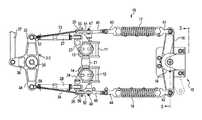
- FIG. 1is a plan view showing an apparatus for controlling an aircraft nose wheel steering system according to an exemplary embodiment of the invention.
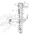
- FIG. 2is a side elevation of the apparatus of FIG. 1 .
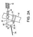
- FIG. 2Ais a fragmentary side elevation on an enlarged scale showing a swivel plate of the apparatus of FIG. 1 in its pivoted position.
- FIG. 3is a sectional view on an enlarged scale of the apparatus of FIGS. 1 and 2 , taken on the line 3 - 3 of FIG. 1 .
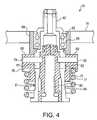
- FIG. 4is a sectional view on an enlarged scale of a lever locking/unlocking device for an apparatus for controlling an aircraft nose wheel steering system according to an exemplary embodiment of the invention.
- FIG. 5is an exploded isometric projection of the lever locking/unlocking device of FIG. 4 .
- FIG. 6is an isometric projection of the lever locking/unlocking device of FIG. 4 , with parts broken away and shown in section.
- FIG. 7schematically illustrates components of a steer-by-wire system according to an exemplary embodiment of the invention.
- FIG. 8is a graph illustrating spring force of a biasing assembly of the apparatus of FIG. 1 relative to displacement of pedals of the apparatus.
- FIGS. 1 , 2 , and 7there is shown a pedal operated apparatus for controlling an aircraft nose wheel steering system 100 for use while on the ground.
- the apparatusincludes a device that centers the nose wheel 105 after a turn is completed and foot pedals 11 , 12 are released.
- the pedal assembly 10includes a right pedal 11 and a left pedal 12 , the pedals being mounted on right and left pedal support arms 13 , 14 respectively, for forward and rearward displacement.
- the pedals 11 , 12are supported by the pedal support arms 13 , 14 so as to have a common neutral position and so that forward displacement of one pedal results in corresponding rearward displacement of the other as shown in dashed lines in FIG. 2 .
- the nose wheel steering systemis a steer by wire system that is enabled only when the aircraft is on the ground, such as in response to a weight sensor signal indicating that the aircraft weight has been applied to the landing gear. With the system enabled, the pilot may displace either pedal 11 , 12 to turn the nose wheel 105 in the respective direction. The pedal displacement is sensed by a transducer 110 , which generates an electrical signal that is supplied to a controller 112 . The controller 112 controls activation of a fluid cylinder 116 via a steering valve actuator 114 to turn the nose wheel 105 and steer the aircraft right or left.
- the pedal support arms 13 , 14are mechanically connected to the aircraft rudder for operating the rudder during flight.
- Various mechanical linkage systems for connecting pedals to an aircraft rudderare well known in the art and no particular system will be described herein.
- the pedal assembly 10includes a nose wheel centering mechanism 15 for returning the aircraft nose wheel to a centered position after completion of a turn and at the same time, returning the pedals 11 , 12 to their neutral position.
- the mechanism 15includes a centering lever 16 mounted on a spindle for pivotal movement about a central vertical axis and spaced aft from the rudder pedals.
- the opposite ends of the arms of the lever 16are connected to the right and left pedal support arms 13 , 14 by right and left helical springs 17 , 18 , respectively.
- the springs 17 , 18are in an at-rest position (no compression/no tension) when the pedals are in the neutral position.
- a predetermined amount of tensionis an amount of tension desired and necessary to return the pedals to the “neutral” position.
- the spring force provided by each individual spring 17 , 18may be less than the total spring force desired. In other words, if identical springs are used on the pilot and copilot pedals, the spring force of each spring 17 , 18 may only be 1 ⁇ 4 of the total spring force desired. If springs are only used on the pilot pedals, then these springs 17 , 18 would each provide 1 ⁇ 2 of the total desired spring force.
- a lever locking/unlocking device 19is provided in order to lock the centering lever 16 in its fixed position when the aircraft is on the ground and to unlock the lever when the aircraft is in flight.
- the device 19is actuated by a signal from a sensor, such as a weight sensor which detects that the weight of the aircraft is being carried by the landing gear.
- the pedal assembly 10is supported on a frame 20 that forms part of the floor of the aircraft.
- the right and left pedal support arms 13 , 14are pivotally supported at their lower ends on a fixed shaft 21 mounted on the frame and extending from side to side.
- Each of the support arms 13 , 14has a bracket 23 , 24 , located below the pedals.
- Each brackethas a pin 25 , 26 mounted in a forked portion of its bracket.
- the pins 25 , 26serve to connect a pair of actuator rods 27 , 28 , respectively, between the brackets and a bell crank 30 .
- the rearward ends of the actuator rods 27 , 28are pivotally connected to the pins 25 , 26 and the forward ends are pivotally connected, through pivot links 31 , 32 to the oppositely extending arms 33 , 34 of the bell crank 30 , which has a “T” shaped configuration.
- the bell crank 30is supported midway between the arms 33 , 34 on a spindle 35 for limited pivotal movement about a vertical axis. With this arrangement, the bell crank 30 serves to interconnect the pedals 11 , 12 so that forward displacement of one pedal results in rearward displacement of the other.
- the bell crank 30also has a forwardly extending leg 36 that connects the pedal assembly 10 to another pedal assembly (e.g., a copilot pedal assembly).
- the connectionis provided by means of a rod 37 that connects the leg 36 to a corresponding bell crank leg forming part of the other pedal assembly.
- a transducer 110( FIG. 7 ) is operatively connected to the rod 37 and serves to detect movement of the rod 37 and, thus, movement of the pedals 11 , 12 .
- the transducer 110communicates the detected movement as an electrical signal to the steering control unit 112 which, in turn, actuates the steering valve actuator 114 and fluid cylinder 116 to turn the nose gear 105 in accordance with the pedal movement.
- the nose wheel centering mechanism 15as briefly described above is enabled only when the aircraft is on the ground so that the pilot can use the foot pedals 11 , 12 to operate the nose wheel steering system 100 .
- the mechanism 15serves to return the nose wheel 105 to its centered position once the pilot releases a foot pedal 11 , 12 that has been displaced forwardly to steer the aircraft.
- the mechanism 15includes as its primary components, the centering lever 16 and the right and left centering springs 17 , 18 .
- the aft ends of the springs 17 , 18each have a fitting 41 , 42 adapted to form a pivotal connection between the respective spring 17 , 18 and the respective end of the lever 16 .
- the forward ends of the springs 17 , 18each have a similar fitting 43 , 44 adapted to form a pivotal connection between the respective spring and one of a pair of links 45 , 46 .
- Each link 45 , 46is in turn pivotally connected to a respective swivel plate 51 , 52 via fasteners 47 , 48 .
- the purpose of the swivel plates 51 , 52is related to the rearward displacement of a pedal support arm 13 , 14 when the other support arm 14 , 13 is displaced forwardly.
- the forward displacement of one pedalstretches the respective spring and increases its tension.
- the other springis compressed until it reaches maximum compression. When the spring reaches its completely compressed condition, it no longer serves as a source of resistance to pedal movement.
- the swivel plates 51 , 52pivot upwardly and forwardly to accommodate further movement of the pedal support arm being rearwardly displaced.
- the swivel plates 51 , 52are each pivotally supported at their forward end by means of the pins 25 , 26 that serve to connect the links 31 , 32 to the support arm brackets 23 , 24 .
- the plates 51 , 52each have an upward extensions between their forward and rearward ends. These upward extensions serve as connection points for a pair of control springs 53 , 54 that are connected to the respective swivel plates by fasteners 55 , 56 .
- the fasteners 55 , 56are so located on the respective swivel plates 51 , 52 that the springs 53 , 54 tend to pivot the plates upwardly and forwardly about the axis of the pins 25 , 26 .
- FIG. 8wherein it is shown that in a region surrounding a neutral position of the pedals, the pilot must work against both springs 17 , 18 , and assuming that the spring force of each spring is equal to F, the total spring force is equal to 2F. However, at a location nearer the end of pedal movement, one of the springs (the compressed spring) is no longer providing a biasing force, and thus the spring force is reduced to 1F. This also is the case, albeit reversed, when the pedals are released. As such, a relatively greater biasing or restorative force is provided near a neutral position, which is helpful in returning the nose wheel 105 to a centered position.
- control springs 53 , 54are pivotally connected to the respective arms 33 , 34 of the bell crank 30 by means of fittings 57 , 58 .
- the springs 53 , 54are mounted in a stretched or tensioned condition so that each spring urges the respective swivel plate 51 , 52 to pivot upwardly whereby the forward ends of the links 45 , 46 are guided in an arc.
- the lever locking/unlocking device 19provides a unique means for accomplishing the locking function.
- the components of the device 19are best shown in FIGS. 3-6 and include a hub 60 integral with the lever 16 and adapted to rotate on a fixed tubular spindle 61 .
- the spindle 61has an upper axial portion 62 having a relatively small diameter, a central axial portion 63 with a somewhat larger diameter, and a lower axial portion 64 with an even larger diameter.
- An annular shoulderis formed at the top of the lower portion 64 .
- the hub 60is mounted for free rotation on the central axial portion 63 of the spindle 61 when the device is unlocked.
- An annular ball bearing assembly 65fits between the inner surface of the hub 60 and the spindle central axial portion 63
- a vertically movable slide 70is mounted on the lower portion 64 of the spindle 61 and is adapted to move in a vertical path between an upward position in locking engagement with the hub 60 and a downward position wherein the hub 60 is unlocked.
- the slide 70is limited to vertical movement and its angular position relative to the spindle 61 remains fixed.
- the hub 60has opposed notches 66 , 67 formed in the lower portion of its tubular wall.
- the notches 66 , 67are adapted to cooperate with latching teeth 68 , 69 formed in the slide 70 .
- the notches 66 , 67each have a detent 71 , 72 that is adapted to receive one of the latching teeth 68 , 69 .
- the centering lever 16 and hub 60may not be in the correct angular position for locking.
- a meansmust be provided to rotate the lever 16 and hub 60 to the correct position so that the teeth 68 , 69 can properly engage the detents 71 , 72 .
- the notches 66 , 67have a pair of downwardly facing ramp portions 73 , 74 formed on opposite sides of their respective detent 71 , 72 .
- Either of the ramp portions 73 , 74may be engaged by one of the latching teeth 68 , 69 during the upward movement of the slide 70 to rotate the hub 60 in the direction necessary to bring the teeth 68 , 69 into engagement with the detents 71 , 72 .
- the slide 70includes a sleeve portion 75 and a radial flange 76 at the upper end.
- the teeth 68 , 69are located on the top face of the flange 76 .
- a helical spring 77fits over the outer surface of the sleeve portion 75 and rests against the lower surface of the flange 76 .
- the spring 77urges the slide 70 upward to its locking position.
- the spring 77may be compressed sufficiently to permit the slide 70 to move downwardly to its unlocked position.
- the slide 70is driven in a vertical path of travel by pins 79 , 80 secured in holes formed in the latching teeth 68 , 69 .
- the pins 79 , 80extend radially inward through vertical slots 81 , 82 located on opposite sides of the lower portion 64 of the spindle 61 .
- the engagement between the pins 79 , 80 and the sides of the slots 81 , 82assures that the slide 70 is confined to a vertical path of travel.
- the pins 79 , 80extend radially inward beyond the inner wall of the spindle 61 into the interior space therewithin.
- a rotor 85is received inside the lower portion 64 of the spindle 61 for selective rotation in a 90-degree angular path of travel.
- the rotor 85rotates both clockwise and counterclockwise.
- the outer surface of the rotoris provided with a pair of helical grooves 86 , 87 that extend around the cylindrical surface about 90 degrees.
- the grooves 86 , 87include a flat portion (only one shown, 86 a ) to receive and hold the pins 79 , 80 and prevent the spring 77 from moving the rotor 85 and thereby helps to hold the pins/rotor in the unlocked position.
- the inner ends of the pins 79 , 80each extend into one of the respective grooves 86 , 87 .
- the slide 70is urged upward by the helical spring 77 into its locking position in which the teeth 68 , 69 are seated in the detents 71 , 72 .
- the rotor 85is connected to a rotary actuator 90 mounted on the frame 20 below the device 19 .
- the actuator 90is adapted to turn the rotor 85 in 90 degree increments in forward and reverse directions.
- the actuator 90is controlled by a signal, such as a signal from a sensor in response to whether or not the weight of the aircraft is being carried by the aircraft landing gear. It is contemplated that other signals indicative of the aircraft being on the ground could be used instead of the weight signal.
- the device 19when the aircraft is on the ground, the device 19 is in its locked condition and the centering lever 16 is turned to its position shown in FIG. 1 . In this condition the springs 17 , 18 urge the pedals 11 , 12 to their neutral position and the nose wheel to its centered position.
- the device 19when the aircraft is in flight, the device 19 is in its unlocking condition and the centering lever 16 is free to pivot about its axis with no effect on the pedals.
Landscapes
- Engineering & Computer Science (AREA)
- Aviation & Aerospace Engineering (AREA)
- Mechanical Engineering (AREA)
- Automation & Control Theory (AREA)
- Mechanical Control Devices (AREA)
Abstract
Description
Claims (19)
Priority Applications (1)
| Application Number | Priority Date | Filing Date | Title |
|---|---|---|---|
| US12/415,120US8544791B2 (en) | 2008-03-31 | 2009-03-31 | Pedal operated apparatus for controlling an aircraft nose wheel steering system |
Applications Claiming Priority (2)
| Application Number | Priority Date | Filing Date | Title |
|---|---|---|---|
| US4090108P | 2008-03-31 | 2008-03-31 | |
| US12/415,120US8544791B2 (en) | 2008-03-31 | 2009-03-31 | Pedal operated apparatus for controlling an aircraft nose wheel steering system |
Publications (2)
| Publication Number | Publication Date |
|---|---|
| US20100044500A1 US20100044500A1 (en) | 2010-02-25 |
| US8544791B2true US8544791B2 (en) | 2013-10-01 |
Family
ID=41135914
Family Applications (1)
| Application Number | Title | Priority Date | Filing Date |
|---|---|---|---|
| US12/415,120Active2032-06-30US8544791B2 (en) | 2008-03-31 | 2009-03-31 | Pedal operated apparatus for controlling an aircraft nose wheel steering system |
Country Status (4)
| Country | Link |
|---|---|
| US (1) | US8544791B2 (en) |
| EP (1) | EP2259967B1 (en) |
| ES (1) | ES2394761T3 (en) |
| WO (1) | WO2009124032A1 (en) |
Cited By (11)
| Publication number | Priority date | Publication date | Assignee | Title |
|---|---|---|---|---|
| US8894005B2 (en)* | 2011-04-02 | 2014-11-25 | Sumitomo Precision Products Co., Ltd. | Landing gear assembly of aircraft |
| RU2539620C1 (en)* | 2013-12-17 | 2015-01-20 | Открытое акционерное общество "Московский институт электромеханики и автоматики" | Aircraft landing control by heading |
| US8955425B2 (en) | 2013-02-27 | 2015-02-17 | Woodward, Inc. | Rotary piston type actuator with pin retention features |
| US9163648B2 (en) | 2013-02-27 | 2015-10-20 | Woodward, Inc. | Rotary piston type actuator with a central actuation assembly |
| US9234535B2 (en) | 2013-02-27 | 2016-01-12 | Woodward, Inc. | Rotary piston type actuator |
| US9476434B2 (en) | 2013-02-27 | 2016-10-25 | Woodward, Inc. | Rotary piston type actuator with modular housing |
| US9593696B2 (en) | 2013-02-27 | 2017-03-14 | Woodward, Inc. | Rotary piston type actuator with hydraulic supply |
| US9631645B2 (en) | 2013-02-27 | 2017-04-25 | Woodward, Inc. | Rotary piston actuator anti-rotation configurations |
| US9816537B2 (en) | 2013-02-27 | 2017-11-14 | Woodward, Inc. | Rotary piston type actuator with a central actuation assembly |
| US11199248B2 (en) | 2019-04-30 | 2021-12-14 | Woodward, Inc. | Compact linear to rotary actuator |
| US11333175B2 (en) | 2020-04-08 | 2022-05-17 | Woodward, Inc. | Rotary piston type actuator with a central actuation assembly |
Families Citing this family (8)
| Publication number | Priority date | Publication date | Assignee | Title |
|---|---|---|---|---|
| US20100096822A1 (en)* | 2008-10-17 | 2010-04-22 | Glenn David Swenson | Motorcycle foot steering |
| CN102815394A (en)* | 2012-08-13 | 2012-12-12 | 湖南山河科技股份有限公司 | Light aircraft rudder spring centering positioning mechanism |
| US10180699B1 (en) | 2013-08-08 | 2019-01-15 | The United States Of America As Represented By The Administrator Of The National Aeronautics And Space Administration | System, apparatus and method for pedal control |
| US9562581B2 (en)* | 2014-03-28 | 2017-02-07 | Bell Helicopter Textron Inc. | Spring tension adjustment mechanism |
| GB2540182A (en)* | 2015-07-08 | 2017-01-11 | Airbus Operations Ltd | Aircraft steering system controller |
| CN106697264A (en)* | 2016-11-30 | 2017-05-24 | 中国航空工业集团公司沈阳飞机设计研究所 | Multi-range position regulating mechanism |
| CN110654531B (en)* | 2019-09-19 | 2022-05-03 | 中国商用飞机有限责任公司 | Pedal system for controlling rudder of airplane and control method thereof |
| CN115636104B (en)* | 2022-09-23 | 2024-09-13 | 陕西飞机工业有限责任公司 | Auxiliary device and method for measuring turning angle of nose landing gear of airplane |
Citations (26)
| Publication number | Priority date | Publication date | Assignee | Title |
|---|---|---|---|---|
| US1620368A (en) | 1926-06-12 | 1927-03-08 | Mcelhaney Frank | Aeroplane |
| US1873906A (en)* | 1930-08-30 | 1932-08-23 | Bendix Brake Co | Operating mechanism |
| US2340237A (en)* | 1941-10-06 | 1944-01-25 | Cons Vultce Aircraft Corp | Control mechanism for airplanes |
| US2379173A (en) | 1940-07-01 | 1945-06-26 | Republic Aviat Corp | Aircraft landing gear |
| US2585688A (en)* | 1947-12-16 | 1952-02-12 | Saulnier Raymond | Aircraft rudder control column |
| US2760739A (en) | 1951-07-09 | 1956-08-28 | James B Reichert | Apparatus for controlling aircraft |
| US2814452A (en) | 1950-10-26 | 1957-11-26 | Bendix Aviat Corp | Aircraft steering control system |
| US2944770A (en)* | 1954-08-04 | 1960-07-12 | Ampatco Lab Corp | Aircraft control system |
| US2998211A (en) | 1959-06-02 | 1961-08-29 | Douglas J Evans | Rudder control system for aircraft |
| US3489376A (en)* | 1967-11-09 | 1970-01-13 | Boeing Co | Aircraft landing gear steering extensible disconnect system |
| US3576302A (en)* | 1968-07-10 | 1971-04-27 | Bendix Corp | Solid-state position sensor for sensing an adjusted position of a control element |
| US3715094A (en)* | 1970-06-05 | 1973-02-06 | Cohn R Inc | Simplified aircraft control system |
| US3753540A (en)* | 1969-10-17 | 1973-08-21 | Ver Flugtechnische Werke | Nose wheel steering |
| US3931943A (en) | 1974-08-30 | 1976-01-13 | Rohr Industries, Inc. | Airplane rudder and controls |
| US4470570A (en)* | 1982-09-29 | 1984-09-11 | The Boeing Company | Control assembly for aircraft |
| US4759515A (en)* | 1986-09-12 | 1988-07-26 | Messerschmitt-Boelkow-Blohm Gesellschaft Mit Beschraenkter Haftung | Drive control for a vertical rudder of an aircraft |
| US4848708A (en)* | 1987-11-13 | 1989-07-18 | The Boeing Company | Adjustable assembly for aircraft rudder, brake and nose landing gear steering control |
| US5056742A (en)* | 1987-11-13 | 1991-10-15 | The Boeing Company | Modular rudder pedal and brake control assembly for aircraft |
| US5100081A (en)* | 1986-10-08 | 1992-03-31 | Dieter Thomas | Aircraft control system |
| US5158459A (en) | 1990-07-05 | 1992-10-27 | Ralph Edelberg | Freestanding integrated control stick, rudder pedals, and throttle for computerized aircraft flight simulation program |
| US5482228A (en)* | 1992-10-05 | 1996-01-09 | Honda Giken Kogyo Kabushiki Kaisha | Landing gear assembly for airplane |
| US5613651A (en) | 1994-12-08 | 1997-03-25 | The Boeing Company | Landing gear axle steering without walking beam |
| US5725184A (en) | 1995-06-01 | 1998-03-10 | Agency For Defense Development | Brake rudder pedal system for light aircraft |
| US5878981A (en)* | 1997-04-14 | 1999-03-09 | Dewey; Daniel L. | Flight console for radio controlled aircraft |
| US7690604B2 (en)* | 2006-11-06 | 2010-04-06 | Honeywell International Inc. | Rudder pedal assembly including non-parallel slide rails |
| US7726611B2 (en)* | 2006-06-30 | 2010-06-01 | Honeywell International Inc. | Active rudder pedal mechanism with foreign object strike tolerance and articulating brake |
- 2009
- 2009-03-31WOPCT/US2009/038928patent/WO2009124032A1/enactiveApplication Filing
- 2009-03-31ESES09728345Tpatent/ES2394761T3/enactiveActive
- 2009-03-31USUS12/415,120patent/US8544791B2/enactiveActive
- 2009-03-31EPEP09728345Apatent/EP2259967B1/ennot_activeNot-in-force
Patent Citations (26)
| Publication number | Priority date | Publication date | Assignee | Title |
|---|---|---|---|---|
| US1620368A (en) | 1926-06-12 | 1927-03-08 | Mcelhaney Frank | Aeroplane |
| US1873906A (en)* | 1930-08-30 | 1932-08-23 | Bendix Brake Co | Operating mechanism |
| US2379173A (en) | 1940-07-01 | 1945-06-26 | Republic Aviat Corp | Aircraft landing gear |
| US2340237A (en)* | 1941-10-06 | 1944-01-25 | Cons Vultce Aircraft Corp | Control mechanism for airplanes |
| US2585688A (en)* | 1947-12-16 | 1952-02-12 | Saulnier Raymond | Aircraft rudder control column |
| US2814452A (en) | 1950-10-26 | 1957-11-26 | Bendix Aviat Corp | Aircraft steering control system |
| US2760739A (en) | 1951-07-09 | 1956-08-28 | James B Reichert | Apparatus for controlling aircraft |
| US2944770A (en)* | 1954-08-04 | 1960-07-12 | Ampatco Lab Corp | Aircraft control system |
| US2998211A (en) | 1959-06-02 | 1961-08-29 | Douglas J Evans | Rudder control system for aircraft |
| US3489376A (en)* | 1967-11-09 | 1970-01-13 | Boeing Co | Aircraft landing gear steering extensible disconnect system |
| US3576302A (en)* | 1968-07-10 | 1971-04-27 | Bendix Corp | Solid-state position sensor for sensing an adjusted position of a control element |
| US3753540A (en)* | 1969-10-17 | 1973-08-21 | Ver Flugtechnische Werke | Nose wheel steering |
| US3715094A (en)* | 1970-06-05 | 1973-02-06 | Cohn R Inc | Simplified aircraft control system |
| US3931943A (en) | 1974-08-30 | 1976-01-13 | Rohr Industries, Inc. | Airplane rudder and controls |
| US4470570A (en)* | 1982-09-29 | 1984-09-11 | The Boeing Company | Control assembly for aircraft |
| US4759515A (en)* | 1986-09-12 | 1988-07-26 | Messerschmitt-Boelkow-Blohm Gesellschaft Mit Beschraenkter Haftung | Drive control for a vertical rudder of an aircraft |
| US5100081A (en)* | 1986-10-08 | 1992-03-31 | Dieter Thomas | Aircraft control system |
| US5056742A (en)* | 1987-11-13 | 1991-10-15 | The Boeing Company | Modular rudder pedal and brake control assembly for aircraft |
| US4848708A (en)* | 1987-11-13 | 1989-07-18 | The Boeing Company | Adjustable assembly for aircraft rudder, brake and nose landing gear steering control |
| US5158459A (en) | 1990-07-05 | 1992-10-27 | Ralph Edelberg | Freestanding integrated control stick, rudder pedals, and throttle for computerized aircraft flight simulation program |
| US5482228A (en)* | 1992-10-05 | 1996-01-09 | Honda Giken Kogyo Kabushiki Kaisha | Landing gear assembly for airplane |
| US5613651A (en) | 1994-12-08 | 1997-03-25 | The Boeing Company | Landing gear axle steering without walking beam |
| US5725184A (en) | 1995-06-01 | 1998-03-10 | Agency For Defense Development | Brake rudder pedal system for light aircraft |
| US5878981A (en)* | 1997-04-14 | 1999-03-09 | Dewey; Daniel L. | Flight console for radio controlled aircraft |
| US7726611B2 (en)* | 2006-06-30 | 2010-06-01 | Honeywell International Inc. | Active rudder pedal mechanism with foreign object strike tolerance and articulating brake |
| US7690604B2 (en)* | 2006-11-06 | 2010-04-06 | Honeywell International Inc. | Rudder pedal assembly including non-parallel slide rails |
Cited By (17)
| Publication number | Priority date | Publication date | Assignee | Title |
|---|---|---|---|---|
| US8894005B2 (en)* | 2011-04-02 | 2014-11-25 | Sumitomo Precision Products Co., Ltd. | Landing gear assembly of aircraft |
| US9709078B2 (en) | 2013-02-27 | 2017-07-18 | Woodward, Inc. | Rotary piston type actuator with a central actuation assembly |
| US10030679B2 (en) | 2013-02-27 | 2018-07-24 | Woodward, Inc. | Rotary piston type actuator |
| US9163648B2 (en) | 2013-02-27 | 2015-10-20 | Woodward, Inc. | Rotary piston type actuator with a central actuation assembly |
| US9234535B2 (en) | 2013-02-27 | 2016-01-12 | Woodward, Inc. | Rotary piston type actuator |
| US9476434B2 (en) | 2013-02-27 | 2016-10-25 | Woodward, Inc. | Rotary piston type actuator with modular housing |
| US9593696B2 (en) | 2013-02-27 | 2017-03-14 | Woodward, Inc. | Rotary piston type actuator with hydraulic supply |
| US8955425B2 (en) | 2013-02-27 | 2015-02-17 | Woodward, Inc. | Rotary piston type actuator with pin retention features |
| US9631645B2 (en) | 2013-02-27 | 2017-04-25 | Woodward, Inc. | Rotary piston actuator anti-rotation configurations |
| US9816537B2 (en) | 2013-02-27 | 2017-11-14 | Woodward, Inc. | Rotary piston type actuator with a central actuation assembly |
| US10767669B2 (en) | 2013-02-27 | 2020-09-08 | Woodward, Inc. | Rotary piston type actuator with a central actuation assembly |
| US10458441B2 (en) | 2013-02-27 | 2019-10-29 | Woodward, Inc. | Rotary piston actuator anti-rotation configurations |
| RU2539620C1 (en)* | 2013-12-17 | 2015-01-20 | Открытое акционерное общество "Московский институт электромеханики и автоматики" | Aircraft landing control by heading |
| US11199248B2 (en) | 2019-04-30 | 2021-12-14 | Woodward, Inc. | Compact linear to rotary actuator |
| US11927249B2 (en) | 2019-04-30 | 2024-03-12 | Woodward, Inc. | Compact linear to rotary actuator |
| US12270461B2 (en) | 2019-04-30 | 2025-04-08 | Woodward, Inc. | Compact linear to rotary actuator |
| US11333175B2 (en) | 2020-04-08 | 2022-05-17 | Woodward, Inc. | Rotary piston type actuator with a central actuation assembly |
Also Published As
| Publication number | Publication date |
|---|---|
| US20100044500A1 (en) | 2010-02-25 |
| EP2259967A1 (en) | 2010-12-15 |
| ES2394761T3 (en) | 2013-02-05 |
| EP2259967A4 (en) | 2011-06-08 |
| EP2259967B1 (en) | 2012-09-26 |
| WO2009124032A1 (en) | 2009-10-08 |
Similar Documents
| Publication | Publication Date | Title |
|---|---|---|
| US8544791B2 (en) | Pedal operated apparatus for controlling an aircraft nose wheel steering system | |
| EP2318272B1 (en) | Aircraft landing gear actuator | |
| US5806806A (en) | Flight control mechanical backup system | |
| US7690604B2 (en) | Rudder pedal assembly including non-parallel slide rails | |
| CN102452478B (en) | The removable Flight By Wire of circuit with push-pull type interconnected rod controls post | |
| JP5868057B2 (en) | Active control column with manual switching to passive control column | |
| US7883059B2 (en) | Actuator systems and associated methods for unmanned air vehicles and other applications | |
| EP4025495B1 (en) | Rudder and brake pedal assembly | |
| EP2947005B1 (en) | Aircraft hybrid flight control system | |
| EP3659910B1 (en) | Jam mitigation in aircraft fly-by-wire systems and related methods | |
| CN105667809B (en) | Rudder stock for aircraft | |
| CN115027662B (en) | System and method for mitigating jamming of aircraft controls | |
| EP3056430B1 (en) | Dual-function seat actuator | |
| CN114655424A (en) | An aircraft side stick control device and method supporting active-passive switching | |
| US5538209A (en) | Hardover protection system for an aircraft | |
| EP3056429B1 (en) | Decoupled aircraft seat actuator | |
| CN217624086U (en) | Side rod control device supporting active and passive switching and aircraft | |
| WO2023037071A1 (en) | Vehicle control column comprising a locking device | |
| US20240355222A1 (en) | Flight simulation control apparatus | |
| CN119262275A (en) | Side rod device |
Legal Events
| Date | Code | Title | Description |
|---|---|---|---|
| AS | Assignment | Owner name:HONDA MOTOR CO., LTD.,JAPAN Free format text:ASSIGNMENT OF ASSIGNORS INTEREST;ASSIGNORS:OYAMA, HIROKI;FUJINO, MICHIMASA;REEL/FRAME:022586/0260 Effective date:20090330 Owner name:HONDA MOTOR CO., LTD., JAPAN Free format text:ASSIGNMENT OF ASSIGNORS INTEREST;ASSIGNORS:OYAMA, HIROKI;FUJINO, MICHIMASA;REEL/FRAME:022586/0260 Effective date:20090330 | |
| AS | Assignment | Owner name:HONDA PATENTS & TECHNOLOGIES NORTH AMERICA, LLC, C Free format text:ASSIGNMENT OF ASSIGNORS INTEREST;ASSIGNOR:HONDA MOTOR CO., LTD.;REEL/FRAME:028227/0277 Effective date:20120425 | |
| STCF | Information on status: patent grant | Free format text:PATENTED CASE | |
| CC | Certificate of correction | ||
| FPAY | Fee payment | Year of fee payment:4 | |
| MAFP | Maintenance fee payment | Free format text:PAYMENT OF MAINTENANCE FEE, 8TH YEAR, LARGE ENTITY (ORIGINAL EVENT CODE: M1552); ENTITY STATUS OF PATENT OWNER: LARGE ENTITY Year of fee payment:8 | |
| AS | Assignment | Owner name:AMERICAN HONDA MOTOR CO., INC., CALIFORNIA Free format text:ASSIGNMENT OF ASSIGNORS INTEREST;ASSIGNOR:HONDA PATENTS & TECHNOLOGIES NORTH AMERICA, LLC;REEL/FRAME:061497/0609 Effective date:20180401 | |
| FEPP | Fee payment procedure | Free format text:MAINTENANCE FEE REMINDER MAILED (ORIGINAL EVENT CODE: REM.); ENTITY STATUS OF PATENT OWNER: LARGE ENTITY |