US8544740B2 - Apparatus and method for communicating with an RFID transponder - Google Patents
Apparatus and method for communicating with an RFID transponderDownload PDFInfo
- Publication number
- US8544740B2 US8544740B2US13/214,950US201113214950AUS8544740B2US 8544740 B2US8544740 B2US 8544740B2US 201113214950 AUS201113214950 AUS 201113214950AUS 8544740 B2US8544740 B2US 8544740B2
- Authority
- US
- United States
- Prior art keywords
- transponder
- transceiver
- power level
- energizing
- power
- Prior art date
- Legal status (The legal status is an assumption and is not a legal conclusion. Google has not performed a legal analysis and makes no representation as to the accuracy of the status listed.)
- Expired - Lifetime
Links
Images


Classifications
- G—PHYSICS
- G06—COMPUTING OR CALCULATING; COUNTING
- G06K—GRAPHICAL DATA READING; PRESENTATION OF DATA; RECORD CARRIERS; HANDLING RECORD CARRIERS
- G06K7/00—Methods or arrangements for sensing record carriers, e.g. for reading patterns
- G06K7/10—Methods or arrangements for sensing record carriers, e.g. for reading patterns by electromagnetic radiation, e.g. optical sensing; by corpuscular radiation
- G06K7/10009—Methods or arrangements for sensing record carriers, e.g. for reading patterns by electromagnetic radiation, e.g. optical sensing; by corpuscular radiation sensing by radiation using wavelengths larger than 0.1 mm, e.g. radio-waves or microwaves
- G06K7/10366—Methods or arrangements for sensing record carriers, e.g. for reading patterns by electromagnetic radiation, e.g. optical sensing; by corpuscular radiation sensing by radiation using wavelengths larger than 0.1 mm, e.g. radio-waves or microwaves the interrogation device being adapted for miscellaneous applications
- G06K7/10415—Methods or arrangements for sensing record carriers, e.g. for reading patterns by electromagnetic radiation, e.g. optical sensing; by corpuscular radiation sensing by radiation using wavelengths larger than 0.1 mm, e.g. radio-waves or microwaves the interrogation device being adapted for miscellaneous applications the interrogation device being fixed in its position, such as an access control device for reading wireless access cards, or a wireless ATM
- G06K7/10425—Methods or arrangements for sensing record carriers, e.g. for reading patterns by electromagnetic radiation, e.g. optical sensing; by corpuscular radiation sensing by radiation using wavelengths larger than 0.1 mm, e.g. radio-waves or microwaves the interrogation device being adapted for miscellaneous applications the interrogation device being fixed in its position, such as an access control device for reading wireless access cards, or a wireless ATM the interrogation device being arranged for interrogation of record carriers passing by the interrogation device
- G06K7/10435—Methods or arrangements for sensing record carriers, e.g. for reading patterns by electromagnetic radiation, e.g. optical sensing; by corpuscular radiation sensing by radiation using wavelengths larger than 0.1 mm, e.g. radio-waves or microwaves the interrogation device being adapted for miscellaneous applications the interrogation device being fixed in its position, such as an access control device for reading wireless access cards, or a wireless ATM the interrogation device being arranged for interrogation of record carriers passing by the interrogation device the interrogation device being positioned close to a conveyor belt or the like on which moving record carriers are passing
- G06K7/10445—Methods or arrangements for sensing record carriers, e.g. for reading patterns by electromagnetic radiation, e.g. optical sensing; by corpuscular radiation sensing by radiation using wavelengths larger than 0.1 mm, e.g. radio-waves or microwaves the interrogation device being adapted for miscellaneous applications the interrogation device being fixed in its position, such as an access control device for reading wireless access cards, or a wireless ATM the interrogation device being arranged for interrogation of record carriers passing by the interrogation device the interrogation device being positioned close to a conveyor belt or the like on which moving record carriers are passing the record carriers being fixed to further objects, e.g. RFIDs fixed to packages, luggage, mail-pieces or work-pieces transported on a conveyor belt
- B—PERFORMING OPERATIONS; TRANSPORTING
- B41—PRINTING; LINING MACHINES; TYPEWRITERS; STAMPS
- B41J—TYPEWRITERS; SELECTIVE PRINTING MECHANISMS, i.e. MECHANISMS PRINTING OTHERWISE THAN FROM A FORME; CORRECTION OF TYPOGRAPHICAL ERRORS
- B41J3/00—Typewriters or selective printing or marking mechanisms characterised by the purpose for which they are constructed
- B41J3/407—Typewriters or selective printing or marking mechanisms characterised by the purpose for which they are constructed for marking on special material
- B41J3/4075—Tape printers; Label printers
- G—PHYSICS
- G06—COMPUTING OR CALCULATING; COUNTING
- G06K—GRAPHICAL DATA READING; PRESENTATION OF DATA; RECORD CARRIERS; HANDLING RECORD CARRIERS
- G06K17/00—Methods or arrangements for effecting co-operative working between equipments covered by two or more of main groups G06K1/00 - G06K15/00, e.g. automatic card files incorporating conveying and reading operations
- G06K17/0022—Methods or arrangements for effecting co-operative working between equipments covered by two or more of main groups G06K1/00 - G06K15/00, e.g. automatic card files incorporating conveying and reading operations arrangements or provisions for transferring data to distant stations, e.g. from a sensing device
- G06K17/0025—Methods or arrangements for effecting co-operative working between equipments covered by two or more of main groups G06K1/00 - G06K15/00, e.g. automatic card files incorporating conveying and reading operations arrangements or provisions for transferring data to distant stations, e.g. from a sensing device the arrangement consisting of a wireless interrogation device in combination with a device for optically marking the record carrier
- G—PHYSICS
- G06—COMPUTING OR CALCULATING; COUNTING
- G06K—GRAPHICAL DATA READING; PRESENTATION OF DATA; RECORD CARRIERS; HANDLING RECORD CARRIERS
- G06K7/00—Methods or arrangements for sensing record carriers, e.g. for reading patterns
- G06K7/10—Methods or arrangements for sensing record carriers, e.g. for reading patterns by electromagnetic radiation, e.g. optical sensing; by corpuscular radiation
- G06K7/10009—Methods or arrangements for sensing record carriers, e.g. for reading patterns by electromagnetic radiation, e.g. optical sensing; by corpuscular radiation sensing by radiation using wavelengths larger than 0.1 mm, e.g. radio-waves or microwaves
- G06K7/10019—Methods or arrangements for sensing record carriers, e.g. for reading patterns by electromagnetic radiation, e.g. optical sensing; by corpuscular radiation sensing by radiation using wavelengths larger than 0.1 mm, e.g. radio-waves or microwaves resolving collision on the communication channels between simultaneously or concurrently interrogated record carriers.
- G06K7/10079—Methods or arrangements for sensing record carriers, e.g. for reading patterns by electromagnetic radiation, e.g. optical sensing; by corpuscular radiation sensing by radiation using wavelengths larger than 0.1 mm, e.g. radio-waves or microwaves resolving collision on the communication channels between simultaneously or concurrently interrogated record carriers. the collision being resolved in the spatial domain, e.g. temporary shields for blindfolding the interrogator in specific directions
- G—PHYSICS
- G06—COMPUTING OR CALCULATING; COUNTING
- G06K—GRAPHICAL DATA READING; PRESENTATION OF DATA; RECORD CARRIERS; HANDLING RECORD CARRIERS
- G06K7/00—Methods or arrangements for sensing record carriers, e.g. for reading patterns
- G06K7/10—Methods or arrangements for sensing record carriers, e.g. for reading patterns by electromagnetic radiation, e.g. optical sensing; by corpuscular radiation
- G06K7/10009—Methods or arrangements for sensing record carriers, e.g. for reading patterns by electromagnetic radiation, e.g. optical sensing; by corpuscular radiation sensing by radiation using wavelengths larger than 0.1 mm, e.g. radio-waves or microwaves
- G06K7/10158—Methods or arrangements for sensing record carriers, e.g. for reading patterns by electromagnetic radiation, e.g. optical sensing; by corpuscular radiation sensing by radiation using wavelengths larger than 0.1 mm, e.g. radio-waves or microwaves methods and means used by the interrogation device for reliably powering the wireless record carriers using an electromagnetic interrogation field
- G—PHYSICS
- G06—COMPUTING OR CALCULATING; COUNTING
- G06K—GRAPHICAL DATA READING; PRESENTATION OF DATA; RECORD CARRIERS; HANDLING RECORD CARRIERS
- G06K7/00—Methods or arrangements for sensing record carriers, e.g. for reading patterns
- G06K7/10—Methods or arrangements for sensing record carriers, e.g. for reading patterns by electromagnetic radiation, e.g. optical sensing; by corpuscular radiation
- G06K7/10009—Methods or arrangements for sensing record carriers, e.g. for reading patterns by electromagnetic radiation, e.g. optical sensing; by corpuscular radiation sensing by radiation using wavelengths larger than 0.1 mm, e.g. radio-waves or microwaves
- G06K7/10316—Methods or arrangements for sensing record carriers, e.g. for reading patterns by electromagnetic radiation, e.g. optical sensing; by corpuscular radiation sensing by radiation using wavelengths larger than 0.1 mm, e.g. radio-waves or microwaves using at least one antenna particularly designed for interrogating the wireless record carriers
- G06K7/10336—Methods or arrangements for sensing record carriers, e.g. for reading patterns by electromagnetic radiation, e.g. optical sensing; by corpuscular radiation sensing by radiation using wavelengths larger than 0.1 mm, e.g. radio-waves or microwaves using at least one antenna particularly designed for interrogating the wireless record carriers the antenna being of the near field type, inductive coil
- H—ELECTRICITY
- H04—ELECTRIC COMMUNICATION TECHNIQUE
- H04B—TRANSMISSION
- H04B5/00—Near-field transmission systems, e.g. inductive or capacitive transmission systems
- H04B5/40—Near-field transmission systems, e.g. inductive or capacitive transmission systems characterised by components specially adapted for near-field transmission
- H04B5/45—Transponders
Definitions
- the inventionrelates to RFID systems, operable with a variety of different dimensioned electro-magnetically coupled transponders, working at close proximity, to an RF transceiver antenna that is spatially selective for an individual transponder located in a predetermined transponder operating region to the exclusion of other adjacent transponders, and its application to printers-encoders or other systems utilizing such in UHF RFID systems.
- UHF radio frequency identification (RFID) technologyallows wireless data acquisition and or transmission from and or to active (battery powered) or passive transponders using a backscatter technique.
- RFIDradio frequency identification
- the transponderis exposed to an RF electro-magnetic field by the transceiver that couples with and energizes (if passive) the transponder through electro-magnetic induction and transfers commands and data using a predefined “air interface” RF signaling protocol.
- Anti-collision management techniquesexist to allow near simultaneous reading and writing to numerous closely grouped transponders in a common RF electro-magnetic field.
- anti-collision managementincreases system complexity, cost and delay response.
- anti-collision managementis “blind” in that it cannot recognize where a specific transponder being processed is physically located in the RF electro-magnetic field, for example, which transponder is located proximate the print head of a printer-encoder.
- One way to prevent errors during reading and writing to transponders without using anti-collision managementis to electrically isolate a specific transponder of interest from nearby transponders.
- isolation of transpondershas used RF-shielded housings and/or anechoic chambers through which the transponders are individually passed for personalized exposure to the interrogating RF field. This requires that the individual transponders have cumbersome shielding or a significant spatial separation.
- RFID printers-encodershave been developed which are capable of on-demand printing on labels, tickets, tags, cards or other media with which a transponder is attached or embedded. These printer-encoders have a transceiver for on-demand communicating with the transponder on the individual media to read and/or store data into the attached transponder. For the reasons given, it is highly desirable in many applications to present the media on rolls or other format in which the transponders are closely spaced. However, close spacing of the transponders exacerbates the task of serially communicating with each individual transponder without concurrently communicating with neighboring transponders on the media. This selective communication exclusively with an individual transponder is further exacerbated in printers-encoders designed to print on the media in or near the same space as the transponder is positioned when being interrogated.
- transpondersWhen transponders are supplied attached to a carrier substrate, for example in RFID-attached labels, tickets, tags or other media supplied in bulk rolls, Z-folded stacks or other format, an extra length of the carrier substrate is required to allow one transponder on the carrier substrate to exit the isolated field area before the next transponder in line enters it.
- the extra carrier substrateincreases materials costs and the required volume of the transponder media bulk supply for a given number of transponders. Having increased spacing between transponders may also slow overall printer-encoder throughput.
- the RF shielding and or anechoic chamber configurationwill also require reconfiguration, adding cost, complexity and reducing overall productivity.
- printer-encodersit is desired to print on transponder-mounting media in the same transponder operating region in which the transponder is being read from or written to. This may be very difficult to accomplish if the transponder also must be isolated in a shielded housing or chamber.
- UHF transpondersmay operate in, for example, the 902-928 MHz band in the United States and other ISM bands designated in different parts of the world.
- a conventional one-half wavelength “Forward Wave” microstrip prior art coupler 3consisting of a, for example, rectangular conductive strip 5 upon a printed circuit board 7 having a separate ground plane 9 layer configured for these frequencies.
- One end of the conductive strip 5is connected to transceiver 42 and the other end is connected through terminating resistor 8 to ground plane 9 .
- the conductive strip 5 as shown in FIG. 1has a significant width due to RF design requirements imposed by the need to create acceptable frequency response characteristics.
- This type of prior art coupler 3has been used with UHF transponders that are relatively large compared to the extent of prior art coupler 3 .
- transponders 1As shown by FIGS. 2 a and 2 b , recently developed transponders 1 , designed for operation at UHF frequencies, have one dimension so significantly reduced, here for example a few millimeters wide, that they will be activated upon passage proximate the larger prior art coupler 3 by electro-magnetic power leakage 10 concentrated at either side edge of the conductive strip 5 of prior art coupler 3 .
- the two leakage regions “A” and “B” defined by electro-magnetic power leakage 10are small and relatively far apart, increasing system logical overhead and media conveyance positioning accuracy requirements. If the transponders 1 were placed close together, then multiple transponders 1 might be activated by the physically extensive one-half wavelength “Forward Wave” microstrip prior art coupler 3 .
- the minimum required spacing of these transponders 1 to isolate them, and thus the minimum size of media 11 (assuming that they are embedded one per label or media 11 on carrier substrate 13 )must be large relative to the size of the microstrip coupler 3 .
- Thisalso reduces the cost advantages of using the narrow dimensioned transponder(s) 1 within media 11 , as the media 11 must be much larger than the transponder 1 to achieve adequate RF isolation.
- FIG. 1is a top view of a prior art microstrip forward wave coupler.
- FIG. 2 ais a simplified cut-away side view of a transponder-coupler structure using a prior art forward wave coupler as shown in FIG. 1 , illustrating schematically locations where coupling with a narrow dimensioned transponder supplied in-line with other transponders on a carrier substrate may occur.
- FIG. 2 bis a partial cut-away top schematic view of the prior art forward wave coupler and carrier substrate with embedded transponders of FIG. 2 a.
- FIG. 3is a side schematic view of a media printer according to one embodiment of the invention having an improved RFID interrogation system.
- FIG. 4 ais a top view of a coupler according to one embodiment of the invention.
- FIG. 4 bis a top view of a coupler according to another embodiment of the invention.
- FIG. 5 ais a simplified cut-away side view of a transponder-coupler structure using a coupler according to the invention, illustrating schematically the spaced apart areas where coupling with a narrow dimensioned transponder supplied in-line with other transponders on a carrier substrate may occur.
- FIG. 5 bis a partial cut-away top schematic view of the coupler according to the invention and carrier substrate with embedded transponders of FIG. 5 a.
- FIGS. 6 a and 6 bare top views of carrier substrates illustrating different positions of the RFID transponders according to other embodiments of the present invention.
- FIG. 7is a graph illustrating the power levels at which the transceiver can communicate with an exemplary transponder at a particular distance from the transponder.
- FIG. 8is a chart illustrating a look-up table according to one embodiment of the present invention for providing values characteristic of power levels of the transceiver for communicating with particular types of transponders.
- FIG. 9is a three-dimensional chart illustrating the read success rate for a particular type of transponder at different power levels and positions relative to the transceiver.
- FIG. 9 ais a color three-dimensional chart corresponding to FIG. 9 .
- FIG. 10is a two-dimensional chart corresponding to FIG. 9 .
- FIG. 10 ais a color two-dimensional chart corresponding to FIG. 10 .
- FIG. 11is a three-dimensional chart illustrating the read success rate for a particular type of transponder at different frequencies and positions relative to the transceiver.
- FIG. 11 ais a color three-dimensional chart corresponding to FIG. 11 .
- FIG. 12is a two-dimensional chart corresponding to FIG. 11 .
- FIG. 12 ais a color two-dimensional chart corresponding to FIG. 12 .
- the present inventionconcerns apparatus and method which enables an RFID transceiver (sometimes termed herein an “interrogator”) to communicate selectively and exclusively with a single UHF transponder 1 when one or more other similar transponders are in close proximity, without the need for physical isolation or cumbersome shielded housings or chambers.
- an RFID transceiversometimes termed herein an “interrogator”
- the inventionis useful in the reading and or data loading of UHF transponders, for example on an assembly line, in distribution centers or warehouses where on-demand RFID labeling is required, and in a variety of other applications.
- a transponder or a number of transpondersare mounted or embedded on or in a label, ticket, tag, card or other media carried on a liner or carrier. It is often desirable to be able to print on the media before, after, or during communication with a transponder.
- this inventionis disclosed here in a specific embodiment for use with a direct thermal or thermal transfer printer, it may also be used with any type of spatially selective RFID interrogation device or other types of printers using other printing technologies, including inkjet, dot-matrix, and electro-photographic methods.
- a print stationmay be at a distance from the RFID transceiver; in others it may be necessary to accomplish the print function in the same target space occupied by the transponder when it is being interrogated.
- FIG. 3illustrates by way of example only an implementation of the invention in a thermal transfer media printer 16 in which both printing and transponder communication are accomplished, but at different locations in the media printer 16 .
- the media printer 16includes a printhead sub-assembly comprising a conventional thermal printhead 18 and platen roller 19 , as in a direct thermal printer for printing on thermally-sensitive media.
- a web 24 of media 11such as labels, tickets, tags or cards, is directed along a feed path 26 under the printhead 18 where on-demand printing of text, bar codes and/or graphics takes place under control of a computer or microprocessor (not shown).
- the media 11follows a media exit path 34 and may be peeled off the underlying carrier substrate 13 at a peeler bar 32 .
- the liner or carrier substrate 13 for the mediais guided out of the media printer 16 by a roller 36 where it exits the printer along a carrier exit path 38 .
- a ribbon supply roll 28delivers a thermal transfer ribbon (not shown for clarity) between printhead 14 and the media on web 24 . After use, the spent ribbon is collected on a take-up reel 22 .
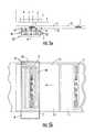
- the media printer 16includes a transceiver 42 for generating RF communication signals that are fed to a frequency and spatially selective microstrip near field coupler 30 located proximate the media feed path 26 .
- the system(including transceiver 42 and near field coupler 30 ) forms a near field pattern in the location of a transponder operating region C (see FIG. 5A ).
- the systemis configured to establish at predetermined transceiver power levels a mutual coupling which exclusively activates and communicates with a single transponder 1 located in the transponder operating region C.
- the media printer 16When the media printer 16 is configured as a direct thermal printer, the heating elements form image dots by thermochromic color change in the heat sensitive media; when the media printer 16 is configured as a thermal transfer printer, then ink dots are formed by melting ink from the thermal transfer ribbon (not shown for clarity) delivered between printhead 18 and the media on web 24 from ribbon supply roll 28 . Patterns of printed dots thus form the desired information indicia on the media 11 , such as text, bar codes or graphics.
- the near field coupler 30according to the invention and its manner of operation will now be described with reference to FIGS. 4 a - 5 b .
- One embodiment of the near field coupler 30is configured for use, for example, with UHF RFID transponders.
- the RFID transponders 1may be bulk supplied on a carrier substrate 13 attached to or embedded within label, ticket, card or tag media 11 .
- the near field coupler 30comprises an array of lines 50 , as shown for example in FIGS. 4 a and 4 b .
- the near field coupler 30may be configured as a segment of unmatched line 50 upon a dielectric substrate, for example a printed circuit board 7 , having a ground plane 9 formed on a spaced apart isolated layer, for example the reverse side of the printed circuit board 7 .
- One end of the array of lines 50is connected to the transceiver 42 ; the other end is connected to the ground plane 9 by means of terminating resistor 8 .
- Signals generated by the transceiver 42 passing along the transmission linegenerate a near field effect emanating from the transmission line edges that couples with a transponder 1 passing through the transponder operating region.
- Another description for the near field effectis “leaky”, as discussed in “Leaky Fields on Microstrip” L. O. McMillian et al. Progress in Electromagnetics Research, PIER 17, 323-337, 1997 and hereby incorporated by reference in the entirety.
- the prior rectangular conductive stripis therefore replaced with an array formed by a plurality of commonly fed and terminated, i.e., electrically parallel, line(s) 50 , as shown for example in FIGS. 4 a and 4 b .
- the plurality of line(s) 50therefore creates an array of leaky edges as shown in FIG. 5 a ; each leaky edge creating an electro-magnetic power leakage 10 at several points within transponder operating region C.
- the resulting line arrayhas similar overall width to the prior solid microstrip coupler 3 and may be similarly tuned, by adjusting the length, spacing and dielectric properties between the line(s) 50 and the ground plane 9 as well as the number of line(s) 50 and or individual line widths, shapes and inter-spacing, to adjust the overall array as an integrated single electrical structure to have the desired frequency response characteristics and generate a combined near field effect corresponding to a desired transponder operating region.
- the overall transponder operating region C resulting from a near field coupler 30 according to the inventionis substantially uniform.
- the distance between the coupler 30 and the web 24is selected for critical coupling. That is, the distance is selected to be that which delivers maximum power short of being so close to the web 24 that the passing transponder(s) 1 causes the effective impedance of the coupler 30 to unacceptably vary.
- the coupler 30may be placed close to the web 24 due to available space and or other design considerations such as placement of the transponder operating region C proximate the printhead 18 . Where the coupler 30 and the web 24 are at a close proximity to one another an impedance mismatch may occur as electrical interaction with passing transponder(s) 1 varies the effective impedance of the coupler 30 . Impedance mismatch will decrease coupling range for a given output power and with significant impedance variances may cause narrow null gaps in the operational region C, for example as illustrated by d, e, f, and g in FIG. 5 a , between the individual fields emitted by each line 50 .
- Simplified logic added to the media transport systemmay be used to move the media 11 forward a small increment, for example 1-2 millimeters if a transponder 1 in the transponder operating region C falls upon a null gap and transponder communications is lost.
- the null gaps and the ability to control their presence by manipulating the location of the coupler 30 with respect to the web 24are evidence of the extremely local field concentrations produced by the near field effect and the precision with which the transponder operating region may be configured to have a wide area with sharply defined boundaries. These characteristics make the near field coupler 30 useful for eliminating precision transponder placement requirements for media suppliers, complex transponder location and tracking logic in media supply systems, as well as any requirements for shielding or increased transponder placement tolerance requirements.
- the increased transponder operating region Callows users increased freedom to place embedded transponder(s) 1 in media 11 at desired locations, for example to avoid the printing degradation that may occur when the printhead encounters a media surface irregularity due to the presence of a RFID transponder 1 .
- the array of lines 50 of the near field coupler 30may be formed by a plurality of straight line(s) 50 as shown in FIG. 4 a .
- a zig-zag or wigglemay be applied to each line 50 , as shown for example in FIG. 4 b to further reduce the appearance and/or depth of the field strength gaps d, e, f and g.
- zig-zagis defined as a characteristic of a line having an overall length characteristic, but a plurality of direction changes internal to the overall length of the line. The direction changes may, for example, be sharply defined or occur as smooth curves.
- a simplified transponder 1 read and or write systemmay be formed without printing capabilities by positioning a near field coupler 30 coupled to a transceiver 42 proximate a media conveyance 25 moving sequential transponders 1 through a transponder operating region C. This structure is also useful where the media 11 is unprinted, or printed upon at another location.
- the near field coupler 30is not limited to a dual plane structure.
- the near field coupler 30may be co-planar, i.e., the ground plane and the array of lines 50 may be located, electrically isolated from each other, in the same plane of a printed circuit board but on different traces.
- the lines 50need not be co-planar, but may form a 3-dimensional structure.
- the lines 50may be on multiple layers of a printed circuit board or formed as a wire frame of lines 50 without use of printed circuit board technology.
- the spatially-selective near field property and the lack of any other shielding requirements of the near field coupler 30 according to the inventionallows the economical addition of a compact, spatially-selective transponder communication module in devices such as printer-encoders.
- the near field coupler 30may be configured to be selective exclusively for a single transponder located in the transponder operating region C, it is now possible by this invention to use a web 24 of media having transponders which are closely spaced on the web 24 , as shown for example in the figures of this specification.
- Prior to this inventionit was extremely difficult to communicate with just one electro-magnetically-coupled UHF transponder, which may have a wide number of different physical configurations, in a closely spaced series of transponders without simultaneously activating adjacent transponders.
- the printer 16can be configured to energize the transceiver 42 to different power levels for communicating with the transponders 1 .
- the transceiver 42can be controlled by a controller 60 , as shown in FIG. 3 .
- the controller 60can be a printer controller that controls other functions of the printer 16 , such as the operation of the print head 18 , delivery of the web 24 of media 11 , and the like.
- the controller 60can operate according to predetermined instructions, such as a software program that is stored in a memory 62 .
- the controller 60can be configured to operate the transceiver 42 at a higher power while writing to each transponder 1 than while reading from the transponder 1 .
- each transponder 1is first read by the transceiver 42 and then subjected to a subsequent write/read operation.
- the transceiver 42can retrieve data from the transponder 1 such as the type of transponder 1 , a serial number that identifies the particular transponder 1 , information about the media 11 to which the transponder 1 is being attached, or the like.
- the transceiver 42can determine by the first read operation whether the transponder 1 is defective.
- the transceiver 42writes data to the transponder 1 and then reads at least some of the data from the transponder 1 to verify that the transponder 1 is operating correctly, i.e., that the data was actually stored in the transponder 1 during the write operation.
- the controller 60can operate the transceiver 42 at a first power level during each of the read operations, and at a second, higher power level during the write operation.
- the power levels for each of the reading and writing operationscan be optimized to provide effective reading and writing of a particular transponder 1 without reading or writing other transponders 1 on the carrier substrate 13 .
- the reading and writing operationscan be performed in any order, i.e., with either a reading or writing operation occurring first, and a reading or writing operation occurring thereafter. Further, the designation of the power levels as “first” and “second” does not indicate the temporal occurrence or use of the power levels.
- the transceiver 42typically, for a transponder 1 in a particular proximity with the near field coupler 30 , the transceiver 42 must provide a greater power for writing to the transponder 1 than for reading from the transponder 1 . That is, the power requirement for writing to the transponder 1 is higher than the power requirement for reading.
- the transceiver 42can be powered at a higher level during the writing operations so that the transceiver 42 can write to the transponder 1 whenever the transponder 1 is sufficiently close for reading by the transceiver 42 at the lower reading power.
- the transceiver 42can be configured so that the region in which the transceiver 42 can effectively write to the transponder 1 is the same, or substantially the same, as the region in which the transceiver 42 can effectively read from the transponder 1 .
- the controller 60can provide sufficient power for reading from and writing to a particular transponder 1 , while preventing both reading from and writing to other transponders 1 that are outside a designated positional range.
- a higher power level during the writing operationgenerally increases the likelihood of the transceiver 42 writing to the transponder 1 , despite variations in the location and configuration of the transponder 1 .
- the transponder 1can have a relatively short dimension in the feed direction of the carrier substrate 13 so that the transponders 1 define relatively long spaces therebetween and only one transponder 1 is affected by the different leakage regions of the narrow field coupler 30 .
- each transponder 1can extend by a greater distance in the feed direction along the feed path 26 of the printer 16 , such that the space between the transponders 1 is reduced.
- the placement of the transponders 1 on the carrier substrate 13can be nonuniform. That is, some of the transponders 1 can be closer to one of the transverse edges of the carrier substrate 13 , and/or successive transponders 1 along the carrier substrate 13 can define nonuniform distances therebetween. In some cases, such variations and/or nonuniformities in the configuration and placement of the transponders 1 can increase the effective distance between the near field coupler 30 and the transponder 1 being read or written.
- the transceiver 42can still write to a particular one of the transponders 1 even if the transponder 1 is further from the transceiver 42 .
- the transceiver 42can read from the particular transponder 1 using a lower reading power to avoid reading from other transponders.
- the power level of the transceiver 42 during the reading and writing operationsaffects the likelihood of the transceiver 42 successfully reading from or writing to the transponder 1 .
- a range of power levelscan be used for reading from or writing to each of the transponders 1 .
- the power level of the transceiver 42 during a reading or writing operationis too low, the transceiver 42 will not successfully communicate with the transponder 1 , i.e., data will not be read from or written to the transponder 1 .
- the power level of the transceiver 42is too high, the transponder 1 will be rendered inactive, and the communication will fail.
- the minimum and maximum power levels of the transceiver 42 for communicating with the transponder 1is affected by a number of characteristics of the components and operating conditions. For example, different types of transponders 1 are characterized by different antennas, chips, and operating protocols. Therefore, each type of transponder 1 typically has different requirements including the required power level of the signal from the transceiver 42 during communication. In fact, even among transponders 1 of a particular type, slight variations in the structure of each transponder 1 can affect the sensitivity of each transponder 1 and, hence, the power requirements for communication. In some cases, the power requirements for transponders 1 of the same type vary by 50% or more.
- the power required for communicating with the transponder 1is determined, in part, by the proximity of the transponder 1 to the transceiver 42 and/or the near field coupler 30 . That is, if the transponder 1 is closer to the near field coupler 30 , the minimum power level for communication therebetween is typically less than if the transponder 1 is farther from the near field coupler 30 . If the transponders 1 are arranged nonuniformly on the carrier substrate 13 such as is illustrated in FIG. 6 b , or if the carrier substrate 13 is not advanced by uniformly incremental distances along the feed path 26 , varying power levels may be required for communication between the transceiver 42 and the transponders 1 .
- the transponders 1typically have different sensitivities at different operating frequencies.
- the transceiver 42operates at a nominal frequency, such as 915 MHz
- the actual operating frequency of the transceiver 42varies throughout a range of frequencies, such as between about 902 MHz and 928 MHz. Within this range, each transponder 1 may respond to signals of different power levels from the transceiver 42 .
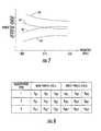
- FIG. 7illustrates the power requirements of the transceiver 42 for communicating with a particular type of transponder 1 , with the transponder 1 positioned in a particular proximity to the transceiver 42 .
- lines 64 , 66are representative of minimum and maximum power levels, respectively, for reading from the transponder 1 at a range of frequencies. That is, if the transceiver 42 is operated below the power level indicated by line 64 or above the power level indicated by line 66 for a particular frequency, the transceiver 42 will not successfully read from the transponder 1 .
- lines 68 , 70are representative of minimum and maximum power levels, respectively, for writing to the transponder 1 at a range of frequencies. That is, if the transceiver 42 is operated below the power level indicated by line 68 or above the power level indicated by line 70 for a particular frequency, the transceiver 42 will not successfully write to the transponder 1 .
- a single power level of the transceiver 42can be used for reading from and writing to the transponder 1 .
- maximum power level for the read operationcan be greater, for some or all frequencies, than the minimum power level for the write operation.
- the transceiver 42can be powered at a power level such as P RW that is within the acceptable ranges of power levels for at least some of the frequencies of operation for both reading and writing.
- the transceiver 42can be powered at one or more different levels during each of the reading and writing operations.
- the valuescan be determined according to maximize the probabilistic chance of achieving successful communication with the transponders 1 .
- Values characteristic of the different power levelscan be stored in the memory 62 , such that the controller 60 can access the values during the different operations and thereby control the transceiver 42 , e.g., according to the different instructions of a software program for controlling the operation of the printer 16 .
- the transceiver 42can be powered at first read and write power levels P R1 , P W1 , respectively, as indicated in FIG. 7 .
- FIG. 8illustrates a look-up table that can be stored in memory 62 and which includes a number of read power levels P R1 , P R2 , P R3 , and write power levels P W1 , P W2 , P W3 .
- the memory 62can include any number of power levels for each type of operation.
- the controller 60can then operate the transceiver 42 at the second power level P R2 during a second attempt to read the transponder 1 , and then at a third power level P R3 during a third attempt to read the transponder 1 .
- the controller 60can attempt to perform the operation at each frequency more than once.
- the controller 60is configured to attempt to perform each operation no more than a predetermined maximum number of times before rejecting the transponder 1 as defective. Of course, if the operation is successful before the predetermined number of attempts is reached, the controller 60 can proceed with the next operation, such as writing to the transponder 1 or communicating with a subsequent transponder 1 .
- the memory 62can store other power levels P R1 ′, P R2 ′, P R3 ′, P W2 ′, P W3 ′, P R1 ′′, P R2 ′′, P R3 ′′, P W1 ′′, P W2 ′′, P W3 ′′ for performing reading and writing operations with other types of transponders 1 or transducers 1 in other configurations.
- the write power level for a particular type of transponder 1can be greater than the read level for the same transponder 1 .
- the write powercan be up to about 3 times as great as the read power.
- the transducer 42can be configured to write to and read from spatial regions that are equal, or substantially equal, in area or size.
- FIGS. 9 , 9 a , 10 , and 10 aillustrate read success rates of a particular type of transponder 1 at different power levels and positions relative to the transceiver 42 .
- a range of “power settings” between 60 and 200are indicated along a first axis of the graph, each power setting corresponding to a particular power value for the transceiver 42 .
- the proximity of the transponder 1 relative to the transceiver 42is indicated by the “label position” measured in millimeters along the feed path 26 of the printer 16 .
- the read success rateis indicated along the third axis, i.e., a percent of the total attempts of reading the transponder 1 .
- FIGS. 10 and 10 aare two-dimensional charts corresponding to FIGS. 9 and 9 a . That is, the power setting and position values are indicated on the two axes, and the success rate is indicated only by intensity/darkness.
- the intensity valuesgenerally correspond with the rates indicated along the third axis of FIGS. 9 and 9 a , i.e., generally ranging from dark/high intensity (low or no success) to light/low intensity (100% success).
- the transceiver 42achieves high success substantially independent of the power of the transceiver 42 .
- the read success rateis high except at very low power settings.
- the transceiver 42communicates with high success, except at low power settings.
- the ranges of positions associated with high success ratesare slightly larger than the ranges of positions at lower power settings.
- a high read success rateis achieved in two significant ranges of position.
- the power settingcan be limited to a range of power settings between about 90 and 110 in order to restrict the positional range of the reading operation, i.e., to prevent reading of multiple transponders 1 along the carrier substrate 13 .
- FIGS. 11 , 11 a , 12 , and 12 aillustrate read success rates of a particular type of transponder 1 at different frequency levels and positions relative to the transceiver 42 . That is, each of FIGS. 11 and 11 a is three-dimensional chart illustrating the read success rate of a particular type of transponder 1 at a particular power, throughout a range of frequencies and positions relative to the transceiver 42 .
- FIGS. 12 and 12 acorrespond to FIGS. 11 and 11 a , with the read success rate indicated only by intensity/darkness. At positions between about 15 and 21 mm and between about 36 and 42 mm, the read success rate is high and substantially independent of frequency.
- a high read success ratecan be achieved by operating the transponder 1 at a power setting of between about 90 and 110, with the transponder 1 at positions of between about 15 and 21 mm. Further, at this range of power settings, the read success rate for transponders 1 located at other positions, e.g., positions greater than about 45 mm, is low. Thus, the transceiver 42 can effectively read from a transponder 1 positioned in a relatively narrow range of positions so that communication with other transponders 1 outside the positional range is prevented.
- the controller 60can be configured to operate the transceiver 42 at different power levels according to other operating parameters such as the type of transponder 1 , the type of carrier substrate 13 or web 24 of media 11 , and the like.
- the sensitivity of the transponder 1 to communication signals from the transceiver 42can be affected by the carrier substrate 13 , the web 24 , or other materials in close proximity to the transponder 1 .
- the transceiver 42can consistently achieve high communication success rates with a transponder 1 in a predetermined position along the feed path 26 while simultaneously preventing inadvertent communication with other transponders 1 on the carrier substrate 13 .
- the controller 60 or other member of the printercan automatically detect the operating parameters, e.g., by reading data from the transponders 1 , so that the controller 60 can automatically use corresponding power levels from the memory 62 .
- an operatorcan enter operating parameters, or the printer 16 can be configured to use predetermined power level(s) regardless of the type of transponder 1 on the carrier substrate 13 .
- a method for communication with a transpondercomprises a) positioning a transponder in a transponder operating region with a transponder axis oriented along a predetermined direction, the smallest dimension of said transponder in said predetermined direction being significantly less than a dimension of said transponder operating region in said predetermined direction; b) with an RF communication signal, forming an array of near field concentrations in said transponder operating region, said near field concentrations extending transversely to said predetermined direction and spaced along said predetermined direction; and c) communicating with said transponder with said RF encoding signal, d) the spacing of said near field concentrations in said predetermined direction being significantly less than said smallest dimension of said transponder in said predetermined direction such that said transponder overlaps and is excited by a plurality of said near field concentrations when located in said transponder operating region.
- a plurality of transpondersis individually communicated with by sequential passage through the transponder axis oriented along a predetermined direction, the
- a method for communication with a transpondercomprises positioning the transponder over a spaced array of near field concentrations of an RF communication signal, the spacing of said near field concentrations being such relative to the dimensions of said transponder that said transponder overlaps and is excited by a plurality of said near field concentrations.
- the spaced arraycan be a parallel array of leaky edges having the near field concentrations.
- the present inventionprovides a method of adaptively communicating with a transponder.
- the methodcomprises positioning the transponder contiguous with a pattern of spaced near field concentrations of an RF communication signal, the pattern having at least one undesired low energy zone within which transponder communication is not optimally performed; exciting the transponder with the near field concentrations; confirming valid communication; if valid communication is not confirmed, moving the transponder a distance; repeating said exciting, confirming, and moving actions until a valid communication of the transponder is confirmed.
- the present inventionalso provides a method for communication with transponders having a range of sizes from smallest to largest.
- the methodprovides a) with an RF communication signal, forming an array of spaced near field concentrations in a transponder operating region, the spacing of said near field concentrations being less than the smaller of the length and width dimensions of said smallest transponder such that all transponders in said range of sizes overlap and are excited by a plurality of said near field concentrations when located proximate said transponder operating region; b) positioning proximate said transponder target sector a transponder having a size in said range of transponder sizes, and c) communicating with said transponder.
- a method for communication with a transponderincludes: with an RF communication signal, forming a near field concentration pattern in a transponder operating region larger than the transponder; locating a transponder at a first position in said transponder operating region; determining a first signal power level operationally effective to communicate with said transponder when located in said first position; storing said associated first power level and transponder position; positioning said transponder or a similar transponder in a second position in said transponder operating region; determining a second signal power level operationally effective to communicate with said transponder when located in said second position; storing said associated second power level and transponder position; and operationally communicating with a series of transponders located in said first and second positions in said transponder operating region using the stored first and second signal power levels respectively associated with the first and second positions of transponders in said transponder operating region.
- the methodalso includes storing a type of the transponder.
Landscapes
- Engineering & Computer Science (AREA)
- Physics & Mathematics (AREA)
- Health & Medical Sciences (AREA)
- Toxicology (AREA)
- Theoretical Computer Science (AREA)
- General Physics & Mathematics (AREA)
- Computer Networks & Wireless Communication (AREA)
- Electromagnetism (AREA)
- General Health & Medical Sciences (AREA)
- Artificial Intelligence (AREA)
- Computer Vision & Pattern Recognition (AREA)
- General Engineering & Computer Science (AREA)
- Signal Processing (AREA)
- Near-Field Transmission Systems (AREA)
Abstract
Description
Claims (17)
Priority Applications (1)
| Application Number | Priority Date | Filing Date | Title |
|---|---|---|---|
| US13/214,950US8544740B2 (en) | 2004-06-10 | 2011-08-22 | Apparatus and method for communicating with an RFID transponder |
Applications Claiming Priority (3)
| Application Number | Priority Date | Filing Date | Title |
|---|---|---|---|
| US57854404P | 2004-06-10 | 2004-06-10 | |
| US11/121,208US8596532B2 (en) | 2004-06-10 | 2005-05-03 | Apparatus and method for communicating with an RFID transponder |
| US13/214,950US8544740B2 (en) | 2004-06-10 | 2011-08-22 | Apparatus and method for communicating with an RFID transponder |
Related Parent Applications (1)
| Application Number | Title | Priority Date | Filing Date |
|---|---|---|---|
| US11/121,208DivisionUS8596532B2 (en) | 2004-06-10 | 2005-05-03 | Apparatus and method for communicating with an RFID transponder |
Publications (2)
| Publication Number | Publication Date |
|---|---|
| US20120038951A1 US20120038951A1 (en) | 2012-02-16 |
| US8544740B2true US8544740B2 (en) | 2013-10-01 |
Family
ID=35459478
Family Applications (4)
| Application Number | Title | Priority Date | Filing Date |
|---|---|---|---|
| US11/121,208Active2029-06-22US8596532B2 (en) | 2004-06-10 | 2005-05-03 | Apparatus and method for communicating with an RFID transponder |
| US13/214,950Expired - LifetimeUS8544740B2 (en) | 2004-06-10 | 2011-08-22 | Apparatus and method for communicating with an RFID transponder |
| US14/069,315Expired - LifetimeUS9613242B2 (en) | 2004-06-10 | 2013-10-31 | Apparatus and method for communicating with an RFID transponder |
| US14/626,828AbandonedUS20150161426A1 (en) | 2004-06-10 | 2015-02-19 | Apparatus and method for communicating with an rfid transponder |
Family Applications Before (1)
| Application Number | Title | Priority Date | Filing Date |
|---|---|---|---|
| US11/121,208Active2029-06-22US8596532B2 (en) | 2004-06-10 | 2005-05-03 | Apparatus and method for communicating with an RFID transponder |
Family Applications After (2)
| Application Number | Title | Priority Date | Filing Date |
|---|---|---|---|
| US14/069,315Expired - LifetimeUS9613242B2 (en) | 2004-06-10 | 2013-10-31 | Apparatus and method for communicating with an RFID transponder |
| US14/626,828AbandonedUS20150161426A1 (en) | 2004-06-10 | 2015-02-19 | Apparatus and method for communicating with an rfid transponder |
Country Status (1)
| Country | Link |
|---|---|
| US (4) | US8596532B2 (en) |
Cited By (4)
| Publication number | Priority date | Publication date | Assignee | Title |
|---|---|---|---|---|
| US20160188921A1 (en)* | 2014-10-13 | 2016-06-30 | Avery Dennison Retail Information Services, Llc | Reduce inlay pitch singulation |
| US9613242B2 (en) | 2004-06-10 | 2017-04-04 | Zih Corp. | Apparatus and method for communicating with an RFID transponder |
| US9852318B2 (en) | 2003-08-29 | 2017-12-26 | Zih Corp. | Spatially selective UHF near field microstrip coupler device and RFID systems using device |
| US9950541B2 (en) | 2015-05-29 | 2018-04-24 | Avery Dennison Retail Information Services, Llc | Thermal printer and components |
Families Citing this family (21)
| Publication number | Priority date | Publication date | Assignee | Title |
|---|---|---|---|---|
| US7398926B1 (en)* | 2003-10-06 | 2008-07-15 | Applied Wireless Identifications Group, Inc. | Apparatus and method for programming an RFID transponder using a constrained field |
| DE602005025507D1 (en)* | 2004-09-28 | 2011-02-03 | Brother Ind Ltd | WIRELESS LABEL CIRCUIT ELEMENT CONTAINER AND LABEL LABEL GENERATION DEVICE |
| JP4873868B2 (en)* | 2005-02-09 | 2012-02-08 | ルネサスエレクトロニクス株式会社 | Passive RFID semiconductor device, IC tag, IC tag control method, and communication method |
| JP4208855B2 (en)* | 2005-04-08 | 2009-01-14 | キヤノン株式会社 | Sheet conveying apparatus and image forming apparatus |
| FI118193B (en)* | 2005-07-04 | 2007-08-15 | Pentti Lajunen | Measurement system, measurement method and new use of antenna |
| US8078103B2 (en) | 2005-10-31 | 2011-12-13 | Zih Corp. | Multi-element RFID coupler |
| US7936252B2 (en)* | 2005-12-07 | 2011-05-03 | Zih Corp. | Adaptive control for improved RFID transponder read and write performance |
| JP4791883B2 (en)* | 2006-05-12 | 2011-10-12 | 株式会社東芝 | Antenna device and article management system |
| US20080117027A1 (en)* | 2006-11-16 | 2008-05-22 | Zih Corporation | Systems, methods, and associated rfid antennas for processing a plurality of transponders |
| US7832952B2 (en)* | 2007-03-21 | 2010-11-16 | Avery Dennison Corporation | High-frequency RFID printer |
| JP2009000942A (en)* | 2007-06-22 | 2009-01-08 | Brother Ind Ltd | Tag tape, tag tape roll, RFID circuit element cartridge, tag label producing device |
| US9727812B2 (en)* | 2007-07-23 | 2017-08-08 | Avery Dennison Retail Information Services, Llc | RFID device wtih control logic, and method |
| US9108434B2 (en)* | 2007-12-18 | 2015-08-18 | Zih Corp. | RFID near-field antenna and associated systems |
| US8254833B2 (en)* | 2009-05-11 | 2012-08-28 | Zih Corp. | Near field coupling devices and associated systems and methods |
| US8878652B2 (en)* | 2009-11-13 | 2014-11-04 | Zih Corp. | Encoding module, associated encoding element, connector, printer-encoder and access control system |
| JP5722928B2 (en)* | 2013-01-23 | 2015-05-27 | 東芝テック株式会社 | Wireless tag initialization apparatus and wireless tag initialization method |
| CN105574455B (en)* | 2015-11-09 | 2018-01-30 | 北京中电华大电子设计有限责任公司 | A kind of modulation circuit for magnetic coupling communication |
| US10225026B2 (en)* | 2016-06-27 | 2019-03-05 | General Electric Company | System for piston rod monitoring |
| DE102016113302A1 (en)* | 2016-07-19 | 2018-01-25 | Sick Ag | RFID device and method for communicating with at least one RFID transponder |
| US11067683B2 (en)* | 2016-08-23 | 2021-07-20 | Sensormatic Electronics, LLC | Systems and methods for locating items within a facility |
| US11499545B2 (en)* | 2019-07-19 | 2022-11-15 | General Electric Company | Systems and methods for piston rod monitoring |
Citations (76)
| Publication number | Priority date | Publication date | Assignee | Title |
|---|---|---|---|---|
| US3742319A (en) | 1971-03-08 | 1973-06-26 | Communications Transistor Corp | R f power transistor |
| US4371876A (en) | 1978-05-04 | 1983-02-01 | Motorola Inc. | Slot array antenna having a complex impedance termination and method of fabrication |
| US4509039A (en) | 1983-07-05 | 1985-04-02 | Minnesota Mining And Manufacturing Company | Shielded, closely spaced transmit-receiver antennas for electronic article surveillance system |
| EP0414628A2 (en) | 1989-08-25 | 1991-02-27 | George W. Kaltner | Individually fed multiloop antennas for electronic security systems |
| US5006812A (en) | 1989-08-01 | 1991-04-09 | Rockwell International Corporation | Power amplifier with built-in test circuit |
| US5170486A (en)* | 1989-04-21 | 1992-12-08 | Marconi Instruments Limited | Apparatus for synthesizing a composite RF signal suitable for use as a test signal in testing adjacent channel rejection of radio receivers |
| EP0568066A1 (en) | 1992-04-29 | 1993-11-03 | Texas Instruments Incorporated | A method of interrogating a plurality of transponders arranged in the transmission range of an interrogating device and transponders for use in the said method |
| EP0568067A1 (en) | 1992-04-29 | 1993-11-03 | Texas Instruments Incorporated | RFID system with controlled charge |
| US5278571A (en) | 1991-10-16 | 1994-01-11 | Tel Instrument Electronics Corp. | RF coupler for measuring RF parameters in the near-field |
| US5317646A (en) | 1992-03-24 | 1994-05-31 | Xerox Corporation | Automated method for creating templates in a forms recognition and processing system |
| US5369381A (en) | 1990-05-29 | 1994-11-29 | U.S. Philips Corporation | Slow-wave transmission line of the microstrip type and circuit including such a line |
| US5373266A (en) | 1993-11-09 | 1994-12-13 | The United States Of America As Represented By The Secreatry Of The Army | Microstrip directional coupler |
| EP0704815A2 (en) | 1994-09-30 | 1996-04-03 | Hughes Identification Devices, Inc. | High field programmable transponder system and method |
| US5521601A (en) | 1995-04-21 | 1996-05-28 | International Business Machines Corporation | Power-efficient technique for multiple tag discrimination |
| US5587578A (en) | 1994-08-10 | 1996-12-24 | Gemplus | Method and apparatus for optimizing magnetic flux through an electronic label of a contact-free identification system |
| US5608417A (en)* | 1994-09-30 | 1997-03-04 | Palomar Technologies Corporation | RF transponder system with parallel resonant interrogation series resonant response |
| US5652711A (en) | 1995-03-23 | 1997-07-29 | Agfa Gevaert, N.V. | Parallel processing of page description language data stream |
| US5777586A (en) | 1993-03-17 | 1998-07-07 | Luxon; Norval N. | Radiation shielding and range extending antenna assembly |
| GB2321551A (en) | 1996-03-22 | 1998-07-29 | John Wolfgang Halpern | Reading smartcards |
| DE9321478U1 (en) | 1992-08-01 | 1998-08-27 | Diehl Ident GmbH, 90478 Nürnberg | Device for inductive high-frequency interrogation of identification labels |
| US5838253A (en) | 1995-05-17 | 1998-11-17 | Accu-Sort Systems, Inc. | Radio frequency identification label |
| US5983243A (en) | 1996-10-31 | 1999-11-09 | International Business Machines Corporation | Data processing system and method for Preparing a presentation-ready document that produces separate images of fixed and variable data and a bookticket specifying an arrangement of such images |
| US6012083A (en) | 1996-09-24 | 2000-01-04 | Ricoh Company Ltd. | Method and apparatus for document processing using agents to process transactions created based on document content |
| US6067475A (en) | 1998-11-05 | 2000-05-23 | Urologix, Inc. | Microwave energy delivery system including high performance dual directional coupler for precisely measuring forward and reverse microwave power during thermal therapy |
| US6104291A (en) | 1998-01-09 | 2000-08-15 | Intermec Ip Corp. | Method and apparatus for testing RFID tags |
| US6118379A (en) | 1997-12-31 | 2000-09-12 | Intermec Ip Corp. | Radio frequency identification transponder having a spiral antenna |
| US6154137A (en) | 1998-06-08 | 2000-11-28 | 3M Innovative Properties Company | Identification tag with enhanced security |
| US6181287B1 (en) | 1997-03-10 | 2001-01-30 | Precision Dynamics Corporation | Reactively coupled elements in circuits on flexible substrates |
| US6215402B1 (en) | 1998-03-13 | 2001-04-10 | Intermec Ip Corp. | Radio frequency identification transponder employing patch antenna |
| US20010000430A1 (en) | 1999-09-02 | 2001-04-26 | Smith Freddie W. | Transponder modules, RF tagging system, method of operating a transponder module and methods of tagging an object having a conductive surface |
| WO2001035320A1 (en) | 1999-11-08 | 2001-05-17 | Commissariat A L'energie Atomique | Transponder system adapted to ambient noise level |
| US6246326B1 (en) | 1999-05-05 | 2001-06-12 | Intermec Ip Corp. | Performance optimized smart label printer |
| US6267521B1 (en) | 1995-09-22 | 2001-07-31 | Eltron International, Inc. | Computer driven printer with a stripper roller and latching assembly |
| US20010029857A1 (en) | 1998-10-07 | 2001-10-18 | Miguel Heredia | Printer with a device for the driving of transponder chips |
| US20020003498A1 (en) | 2000-05-17 | 2002-01-10 | Luc Wuidart | Electromagnetic field generation antenna for a transponder |
| US6346881B1 (en)* | 2000-03-01 | 2002-02-12 | Samsys Technologies Inc. | Tag evaluation module for radio frequency identification (RFID) systems |
| US6392544B1 (en) | 2000-09-25 | 2002-05-21 | Motorola, Inc. | Method and apparatus for selectively activating radio frequency identification tags that are in close proximity |
| US6409401B1 (en) | 2000-03-30 | 2002-06-25 | Zih Corp. | Portable printer with RFID encoder |
| US6424262B2 (en) | 1998-08-14 | 2002-07-23 | 3M Innovative Properties Company | Applications for radio frequency identification systems |
| EP1224607A1 (en) | 1999-10-18 | 2002-07-24 | Lucatron AG | Method for selecting and writing into rfid-transponders |
| EP1233367A2 (en) | 2001-02-09 | 2002-08-21 | Omron Corporation | Antenna apparatus |
| US6466131B1 (en) | 1996-07-30 | 2002-10-15 | Micron Technology, Inc. | Radio frequency data communications device with adjustable receiver sensitivity and method |
| US6470082B1 (en) | 1995-06-19 | 2002-10-22 | Nippon Telegraph And Telephone Corporation | Communications system using portable recording medium |
| US6473028B1 (en) | 1999-04-07 | 2002-10-29 | Stmicroelectronics S.A. | Detection of the distance between an electromagnetic transponder and a terminal |
| US20020167397A1 (en)* | 1999-07-08 | 2002-11-14 | Kursat Eroglu | Method and apparatus for verifying rfid tags |
| US6486769B1 (en) | 1999-12-22 | 2002-11-26 | Intermec Ip Corp. | Method and system for automatic adjustment and diagnosis of radio frequency identification systems using programmable checktags |
| US6527356B1 (en) | 2000-06-02 | 2003-03-04 | Eastman Kodak Company | Printer capable of forming an image on a receiver substrate according to type of receiver substrate and a method of assembling the printer |
| US20030063001A1 (en) | 2001-10-01 | 2003-04-03 | Hohberger Clive P. | Method and apparatus for associating on demand certain selected media and value-adding elements |
| JP2003132330A (en) | 2001-10-25 | 2003-05-09 | Sato Corp | RFID label printer |
| US20030104848A1 (en)* | 2001-11-30 | 2003-06-05 | Raj Brideglall | RFID device, system and method of operation including a hybrid backscatter-based RFID tag protocol compatible with RFID, bluetooth and/or IEEE 802.11x infrastructure |
| US6593853B1 (en) | 2000-02-18 | 2003-07-15 | Brady Worldwide, Inc. | RFID label printing system |
| US20030173408A1 (en) | 2002-03-18 | 2003-09-18 | Precision Dynamics Corporation | Enhanced identification appliance |
| US20030224805A1 (en) | 2002-05-28 | 2003-12-04 | Pioneer Corporation | Apparatus and method for detecting leaving of cellular telephone |
| EP1394719A1 (en) | 2002-09-02 | 2004-03-03 | EM Microelectronic-Marin SA | Adaptation of the transmission and receiving characteristic of a RFID reader dependent on the electromagnetic background noise |
| US20040095242A1 (en) | 2000-11-03 | 2004-05-20 | Grose Darren J. | Method and apparatus for tracking carcasses |
| US20040178267A1 (en) | 2003-03-11 | 2004-09-16 | Zebra Technologies Corporation | System and Method for Selective Communication with RFID Transponders |
| US20040195319A1 (en) | 2003-04-03 | 2004-10-07 | Forster Ian J. | RFID device detection system and method |
| US6802659B2 (en) | 1996-08-07 | 2004-10-12 | Mats Cremon | Arrangement for automatic setting of programmable devices and materials therefor |
| US20040203605A1 (en) | 2002-03-05 | 2004-10-14 | Safa John Aram | Security arrangement |
| US20050032267A1 (en) | 2003-08-05 | 2005-02-10 | Peikang Liu | RFID device and method of making |
| US20050045724A1 (en) | 2003-08-29 | 2005-03-03 | Zih Corp. | Spatially Selective UHF Near Field Microstrip Coupler Device and RFID Systems Using Device |
| WO2005022445A2 (en) | 2003-08-29 | 2005-03-10 | Zih Corp. | Spatially selective uhf near field microstrip coupler device and rfid systems using device |
| US20050099269A1 (en)* | 2003-11-10 | 2005-05-12 | Diorio Christopher J. | Method and apparatus to configure an RFID system to be adaptable to a plurality of environmental conditions |
| US6899476B1 (en) | 2003-09-12 | 2005-05-31 | Printronix, Inc. | RFID tag, antenna, and printer system |
| US6938976B2 (en) | 1999-06-16 | 2005-09-06 | Eastman Kodak Company | Printer and method therefor adapted to sense data uniquely associated with a consumable loaded into the printer |
| US20050206524A1 (en) | 2004-03-22 | 2005-09-22 | Forster Ian J | Low cost method of producing radio frequency identification tags with straps without antenna patterning |
| US6969134B2 (en) | 2001-10-01 | 2005-11-29 | Zih Corp. | Printer or other media processor with on-demand selective media converter |
| US20050274799A1 (en) | 2004-06-10 | 2005-12-15 | Zih Corp. | Apparatus and method for communicating with an RFID transponder |
| US6985754B1 (en) | 1999-04-26 | 2006-01-10 | Nokia Mobile Phones Limited | Radio terminal for browsing the internet |
| US20060030281A1 (en)* | 2002-11-05 | 2006-02-09 | Roman Brunel | Method for transmit power compensation in a mobile communication terminal and communication terminal for implementing said method |
| US20060037502A1 (en) | 1999-06-16 | 2006-02-23 | Vanguard Identification Systems, Inc. | Printed planar radio frequency identification elements |
| US20060205443A1 (en)* | 2003-04-30 | 2006-09-14 | Sebastien Simoens | Wireless communication unit and method for power saving |
| US7190270B2 (en) | 2004-11-05 | 2007-03-13 | Zih Corp. | System and method for detecting transponders used with printer media |
| US20070063843A1 (en) | 2005-09-21 | 2007-03-22 | Zih Corp. | Multi-layered efficient RFID coupler |
| US20070080867A1 (en) | 2005-09-26 | 2007-04-12 | Hae-Won Son | Antenna using proximity-coupled feed method, RFID tag having the same, and antenna impedance matching method thereof |
| US20070099566A1 (en) | 2005-10-31 | 2007-05-03 | Zih Corp. | Multi-element RFID coupler |
Family Cites Families (17)
| Publication number | Priority date | Publication date | Assignee | Title |
|---|---|---|---|---|
| US3760278A (en) | 1970-12-23 | 1973-09-18 | Thomson Csf | Limited range radiocommunication system |
| JP3123900B2 (en) | 1995-06-30 | 2001-01-15 | 三洋電機株式会社 | Digital cordless telephone equipment |
| JP3693725B2 (en)* | 1995-11-24 | 2005-09-07 | 株式会社日本自動車部品総合研究所 | Automatic response system using transponder |
| US5926133A (en) | 1997-07-21 | 1999-07-20 | Denso Corporation | Differentially corrected position location system and method for mobile communication networks |
| JP2000082277A (en) | 1998-09-04 | 2000-03-21 | Sony Corp | Device corresponding to recording medium |
| US6645327B2 (en) | 1999-04-21 | 2003-11-11 | Intermec Ip Corp. | RF tag application system |
| US6819243B2 (en) | 2000-04-03 | 2004-11-16 | Mikko Keskilammi | Method and apparatus for identifying bulk goods, preferably roll-like bulk goods |
| US6750771B1 (en) | 2000-08-10 | 2004-06-15 | Savi Technology, Inc. | Antenna system and method for reading low frequency tags |
| DE10124222A1 (en)* | 2001-05-18 | 2002-11-21 | Atmel Germany Gmbh | Method for matching an antenna resonant circuit of a passive transponder |
| US6837427B2 (en) | 2001-11-21 | 2005-01-04 | Goliath Solutions, Llc. | Advertising compliance monitoring system |
| US7023341B2 (en)* | 2003-02-03 | 2006-04-04 | Ingrid, Inc. | RFID reader for a security network |
| US7606535B2 (en)* | 2004-04-01 | 2009-10-20 | Harris Stratex Networks, Inc. | Modular wide-range transceiver |
| US8174383B1 (en) | 2004-08-26 | 2012-05-08 | Avante International Technology, Inc. | System and method for operating a synchronized wireless network |
| KR20090052411A (en) | 2007-11-21 | 2009-05-26 | 엘지이노텍 주식회사 | Location Tracking System Using Near Field Communication |
| US8120486B2 (en) | 2008-06-10 | 2012-02-21 | Symbol Technologies, Inc. | Methods and systems for tracking RFID devices |
| US20100177080A1 (en) | 2009-01-13 | 2010-07-15 | Metrologic Instruments, Inc. | Electronic-ink signage device employing thermal packaging for outdoor weather applications |
| US20100177707A1 (en) | 2009-01-13 | 2010-07-15 | Metrologic Instruments, Inc. | Method and apparatus for increasing the SNR at the RF antennas of wireless end-devices on a wireless communication network, while minimizing the RF power transmitted by the wireless coordinator and routers |
- 2005
- 2005-05-03USUS11/121,208patent/US8596532B2/enactiveActive
- 2011
- 2011-08-22USUS13/214,950patent/US8544740B2/ennot_activeExpired - Lifetime
- 2013
- 2013-10-31USUS14/069,315patent/US9613242B2/ennot_activeExpired - Lifetime
- 2015
- 2015-02-19USUS14/626,828patent/US20150161426A1/ennot_activeAbandoned
Patent Citations (88)
| Publication number | Priority date | Publication date | Assignee | Title |
|---|---|---|---|---|
| US3742319A (en) | 1971-03-08 | 1973-06-26 | Communications Transistor Corp | R f power transistor |
| US4371876A (en) | 1978-05-04 | 1983-02-01 | Motorola Inc. | Slot array antenna having a complex impedance termination and method of fabrication |
| US4509039A (en) | 1983-07-05 | 1985-04-02 | Minnesota Mining And Manufacturing Company | Shielded, closely spaced transmit-receiver antennas for electronic article surveillance system |
| US5170486A (en)* | 1989-04-21 | 1992-12-08 | Marconi Instruments Limited | Apparatus for synthesizing a composite RF signal suitable for use as a test signal in testing adjacent channel rejection of radio receivers |
| US5006812A (en) | 1989-08-01 | 1991-04-09 | Rockwell International Corporation | Power amplifier with built-in test circuit |
| EP0414628A2 (en) | 1989-08-25 | 1991-02-27 | George W. Kaltner | Individually fed multiloop antennas for electronic security systems |
| US5369381A (en) | 1990-05-29 | 1994-11-29 | U.S. Philips Corporation | Slow-wave transmission line of the microstrip type and circuit including such a line |
| US5278571A (en) | 1991-10-16 | 1994-01-11 | Tel Instrument Electronics Corp. | RF coupler for measuring RF parameters in the near-field |
| US5317646A (en) | 1992-03-24 | 1994-05-31 | Xerox Corporation | Automated method for creating templates in a forms recognition and processing system |
| EP0568066A1 (en) | 1992-04-29 | 1993-11-03 | Texas Instruments Incorporated | A method of interrogating a plurality of transponders arranged in the transmission range of an interrogating device and transponders for use in the said method |
| US5294931A (en)* | 1992-04-29 | 1994-03-15 | Texas Instruments Deutschland Gmbh | Method of interrogating a plurality of transponders arranged in the transmission range of an interrogating device and transponders for use in the said method |
| EP0568067A1 (en) | 1992-04-29 | 1993-11-03 | Texas Instruments Incorporated | RFID system with controlled charge |
| DE9321478U1 (en) | 1992-08-01 | 1998-08-27 | Diehl Ident GmbH, 90478 Nürnberg | Device for inductive high-frequency interrogation of identification labels |
| US5777586A (en) | 1993-03-17 | 1998-07-07 | Luxon; Norval N. | Radiation shielding and range extending antenna assembly |
| US5373266A (en) | 1993-11-09 | 1994-12-13 | The United States Of America As Represented By The Secreatry Of The Army | Microstrip directional coupler |
| US5587578A (en) | 1994-08-10 | 1996-12-24 | Gemplus | Method and apparatus for optimizing magnetic flux through an electronic label of a contact-free identification system |
| US5608417A (en)* | 1994-09-30 | 1997-03-04 | Palomar Technologies Corporation | RF transponder system with parallel resonant interrogation series resonant response |
| EP0704815A2 (en) | 1994-09-30 | 1996-04-03 | Hughes Identification Devices, Inc. | High field programmable transponder system and method |
| US5652711A (en) | 1995-03-23 | 1997-07-29 | Agfa Gevaert, N.V. | Parallel processing of page description language data stream |
| US5521601A (en) | 1995-04-21 | 1996-05-28 | International Business Machines Corporation | Power-efficient technique for multiple tag discrimination |
| US5838253A (en) | 1995-05-17 | 1998-11-17 | Accu-Sort Systems, Inc. | Radio frequency identification label |
| US6470082B1 (en) | 1995-06-19 | 2002-10-22 | Nippon Telegraph And Telephone Corporation | Communications system using portable recording medium |
| US6267521B1 (en) | 1995-09-22 | 2001-07-31 | Eltron International, Inc. | Computer driven printer with a stripper roller and latching assembly |
| GB2321551A (en) | 1996-03-22 | 1998-07-29 | John Wolfgang Halpern | Reading smartcards |
| US6466131B1 (en) | 1996-07-30 | 2002-10-15 | Micron Technology, Inc. | Radio frequency data communications device with adjustable receiver sensitivity and method |
| US6802659B2 (en) | 1996-08-07 | 2004-10-12 | Mats Cremon | Arrangement for automatic setting of programmable devices and materials therefor |
| US6012083A (en) | 1996-09-24 | 2000-01-04 | Ricoh Company Ltd. | Method and apparatus for document processing using agents to process transactions created based on document content |
| US5983243A (en) | 1996-10-31 | 1999-11-09 | International Business Machines Corporation | Data processing system and method for Preparing a presentation-ready document that produces separate images of fixed and variable data and a bookticket specifying an arrangement of such images |
| US6181287B1 (en) | 1997-03-10 | 2001-01-30 | Precision Dynamics Corporation | Reactively coupled elements in circuits on flexible substrates |
| US6118379A (en) | 1997-12-31 | 2000-09-12 | Intermec Ip Corp. | Radio frequency identification transponder having a spiral antenna |
| US6104291A (en) | 1998-01-09 | 2000-08-15 | Intermec Ip Corp. | Method and apparatus for testing RFID tags |
| US6215402B1 (en) | 1998-03-13 | 2001-04-10 | Intermec Ip Corp. | Radio frequency identification transponder employing patch antenna |
| US6154137A (en) | 1998-06-08 | 2000-11-28 | 3M Innovative Properties Company | Identification tag with enhanced security |
| US6424262B2 (en) | 1998-08-14 | 2002-07-23 | 3M Innovative Properties Company | Applications for radio frequency identification systems |
| US6327972B2 (en) | 1998-10-07 | 2001-12-11 | Meto International Gmbh | Printer with a device for the driving of transponder chips |
| US20010029857A1 (en) | 1998-10-07 | 2001-10-18 | Miguel Heredia | Printer with a device for the driving of transponder chips |
| US6067475A (en) | 1998-11-05 | 2000-05-23 | Urologix, Inc. | Microwave energy delivery system including high performance dual directional coupler for precisely measuring forward and reverse microwave power during thermal therapy |
| US6473028B1 (en) | 1999-04-07 | 2002-10-29 | Stmicroelectronics S.A. | Detection of the distance between an electromagnetic transponder and a terminal |
| US6985754B1 (en) | 1999-04-26 | 2006-01-10 | Nokia Mobile Phones Limited | Radio terminal for browsing the internet |
| US6246326B1 (en) | 1999-05-05 | 2001-06-12 | Intermec Ip Corp. | Performance optimized smart label printer |
| US6938976B2 (en) | 1999-06-16 | 2005-09-06 | Eastman Kodak Company | Printer and method therefor adapted to sense data uniquely associated with a consumable loaded into the printer |
| US20060037502A1 (en) | 1999-06-16 | 2006-02-23 | Vanguard Identification Systems, Inc. | Printed planar radio frequency identification elements |
| US20020167397A1 (en)* | 1999-07-08 | 2002-11-14 | Kursat Eroglu | Method and apparatus for verifying rfid tags |
| US20010000430A1 (en) | 1999-09-02 | 2001-04-26 | Smith Freddie W. | Transponder modules, RF tagging system, method of operating a transponder module and methods of tagging an object having a conductive surface |
| EP1224607A1 (en) | 1999-10-18 | 2002-07-24 | Lucatron AG | Method for selecting and writing into rfid-transponders |
| WO2001035320A1 (en) | 1999-11-08 | 2001-05-17 | Commissariat A L'energie Atomique | Transponder system adapted to ambient noise level |
| US6486769B1 (en) | 1999-12-22 | 2002-11-26 | Intermec Ip Corp. | Method and system for automatic adjustment and diagnosis of radio frequency identification systems using programmable checktags |
| US6593853B1 (en) | 2000-02-18 | 2003-07-15 | Brady Worldwide, Inc. | RFID label printing system |
| US6346881B1 (en)* | 2000-03-01 | 2002-02-12 | Samsys Technologies Inc. | Tag evaluation module for radio frequency identification (RFID) systems |
| US6409401B1 (en) | 2000-03-30 | 2002-06-25 | Zih Corp. | Portable printer with RFID encoder |
| US7023391B2 (en) | 2000-05-17 | 2006-04-04 | Stmicroelectronics S.A. | Electromagnetic field generation antenna for a transponder |
| US20020003498A1 (en) | 2000-05-17 | 2002-01-10 | Luc Wuidart | Electromagnetic field generation antenna for a transponder |
| US6527356B1 (en) | 2000-06-02 | 2003-03-04 | Eastman Kodak Company | Printer capable of forming an image on a receiver substrate according to type of receiver substrate and a method of assembling the printer |
| US20030067504A1 (en) | 2000-06-02 | 2003-04-10 | Spurr Robert W. | Printer capable of forming an image on a receiver substrate according to type of receiver substrate and a method of assembling the printer |
| US6392544B1 (en) | 2000-09-25 | 2002-05-21 | Motorola, Inc. | Method and apparatus for selectively activating radio frequency identification tags that are in close proximity |
| US20040095242A1 (en) | 2000-11-03 | 2004-05-20 | Grose Darren J. | Method and apparatus for tracking carcasses |
| EP1233367A2 (en) | 2001-02-09 | 2002-08-21 | Omron Corporation | Antenna apparatus |
| US6969134B2 (en) | 2001-10-01 | 2005-11-29 | Zih Corp. | Printer or other media processor with on-demand selective media converter |
| US6857714B2 (en) | 2001-10-01 | 2005-02-22 | Zih Corp. | Method and apparatus for associating on demand certain selected media and value-adding elements |
| US20030063001A1 (en) | 2001-10-01 | 2003-04-03 | Hohberger Clive P. | Method and apparatus for associating on demand certain selected media and value-adding elements |
| JP2003132330A (en) | 2001-10-25 | 2003-05-09 | Sato Corp | RFID label printer |
| US20030104848A1 (en)* | 2001-11-30 | 2003-06-05 | Raj Brideglall | RFID device, system and method of operation including a hybrid backscatter-based RFID tag protocol compatible with RFID, bluetooth and/or IEEE 802.11x infrastructure |
| US20040203605A1 (en) | 2002-03-05 | 2004-10-14 | Safa John Aram | Security arrangement |
| US20030173408A1 (en) | 2002-03-18 | 2003-09-18 | Precision Dynamics Corporation | Enhanced identification appliance |
| US20030224805A1 (en) | 2002-05-28 | 2003-12-04 | Pioneer Corporation | Apparatus and method for detecting leaving of cellular telephone |
| US7142815B2 (en) | 2002-09-02 | 2006-11-28 | Em Microelectronics-Marin Sa | Adjustment of the detection, transmission and/or reception parameters of an RFID reader as a function of ambient electromagnetic noise |
| EP1394719A1 (en) | 2002-09-02 | 2004-03-03 | EM Microelectronic-Marin SA | Adaptation of the transmission and receiving characteristic of a RFID reader dependent on the electromagnetic background noise |
| US20060030281A1 (en)* | 2002-11-05 | 2006-02-09 | Roman Brunel | Method for transmit power compensation in a mobile communication terminal and communication terminal for implementing said method |
| US6848616B2 (en) | 2003-03-11 | 2005-02-01 | Zih Corp., A Delaware Corporation With Its Principal Office In Hamilton, Bermuda | System and method for selective communication with RFID transponders |
| US20040178267A1 (en) | 2003-03-11 | 2004-09-16 | Zebra Technologies Corporation | System and Method for Selective Communication with RFID Transponders |
| US20040195319A1 (en) | 2003-04-03 | 2004-10-07 | Forster Ian J. | RFID device detection system and method |
| US20060205443A1 (en)* | 2003-04-30 | 2006-09-14 | Sebastien Simoens | Wireless communication unit and method for power saving |
| US20050032267A1 (en) | 2003-08-05 | 2005-02-10 | Peikang Liu | RFID device and method of making |
| US20050045724A1 (en) | 2003-08-29 | 2005-03-03 | Zih Corp. | Spatially Selective UHF Near Field Microstrip Coupler Device and RFID Systems Using Device |
| WO2005022445A2 (en) | 2003-08-29 | 2005-03-10 | Zih Corp. | Spatially selective uhf near field microstrip coupler device and rfid systems using device |
| US7398054B2 (en) | 2003-08-29 | 2008-07-08 | Zih Corp. | Spatially selective UHF near field microstrip coupler device and RFID systems using device |
| US20050045723A1 (en) | 2003-08-29 | 2005-03-03 | Zih Corp. | Spatially Selective UHF Near Field Microstrip Coupler Device and RFID Systems Using Device |
| US6899476B1 (en) | 2003-09-12 | 2005-05-31 | Printronix, Inc. | RFID tag, antenna, and printer system |
| US6929412B1 (en)* | 2003-09-12 | 2005-08-16 | Printronix, Inc. | RFID tag, antenna, and printer system |
| US20050099269A1 (en)* | 2003-11-10 | 2005-05-12 | Diorio Christopher J. | Method and apparatus to configure an RFID system to be adaptable to a plurality of environmental conditions |
| US20050206524A1 (en) | 2004-03-22 | 2005-09-22 | Forster Ian J | Low cost method of producing radio frequency identification tags with straps without antenna patterning |
| US20050274799A1 (en) | 2004-06-10 | 2005-12-15 | Zih Corp. | Apparatus and method for communicating with an RFID transponder |
| US7190270B2 (en) | 2004-11-05 | 2007-03-13 | Zih Corp. | System and method for detecting transponders used with printer media |
| US20070176781A1 (en) | 2004-11-05 | 2007-08-02 | Zih Corp. | System and method for detecting transponders used with printer media |
| US20070063843A1 (en) | 2005-09-21 | 2007-03-22 | Zih Corp. | Multi-layered efficient RFID coupler |
| US7425887B2 (en) | 2005-09-21 | 2008-09-16 | Zih Corporation | Multi-layered efficient RFID coupler |
| US20070080867A1 (en) | 2005-09-26 | 2007-04-12 | Hae-Won Son | Antenna using proximity-coupled feed method, RFID tag having the same, and antenna impedance matching method thereof |
| US20070099566A1 (en) | 2005-10-31 | 2007-05-03 | Zih Corp. | Multi-element RFID coupler |
Non-Patent Citations (13)
| Title |
|---|
| Extended Search Report for European Patent Application No. 10183731.8, dated Nov. 23, 2010. |
| Extended Search Report for European Patent Application No. 101837755.7, dated Nov. 23, 2010. |
| International Search Report for PCT/US2004/027832, dated May 6, 2005 and Written Opinion. |
| International Search Report for US2004/027832, dated Dec. 30, 2004. |
| K.C. Gupta, Ramesh Garg, Inder Bahl, Prakash Bhartia, Microstrip Lines and Slotlines, Second Edition, 1996, Artech House, Inc. |
| Maloratsky, Couplers Shrink HF/VHF/UHF Designs, Microwaves & RF, pp. 93-96, Jun. 2000, USA. |
| Maloratsky, Design Regular-and Irregular-Print Coupled Lines, Microwaves & RF, pp. 97-106, Sep. 2000 USA. |
| Maloratsky, Improve BPF Performance With Wiggly Coupled Lines, Microwaves & RF, pp. 53-62, Apr. 2002, USA. |
| Maloratsky, Reviewing the Basics of Microstrip Lines, Microwaves & RF, pp. 79-88, Mar. 2000, USA. |
| Maloratsky, Reviewing the Basics of Suspended Striplines, Microwave Journal, Oct. 2002, USA. |
| Maloratsky, The Basics of Print Reciprocal Dividers/Combiners, Microwave Journal, Sep. 2000, USA. |
| Maloratsky, Understand the Basics of Microstrip Directional Couplers, Microwaves & RF, pp. 79-94, Feb. 2001, USA. |
| McMillan, et al., Leaky Fields on Microstrip, Progress in Electromagnetics Research, PIER 17, pp. 323-377, 1997 USA. |
Cited By (12)
| Publication number | Priority date | Publication date | Assignee | Title |
|---|---|---|---|---|
| US9852318B2 (en) | 2003-08-29 | 2017-12-26 | Zih Corp. | Spatially selective UHF near field microstrip coupler device and RFID systems using device |
| US9613242B2 (en) | 2004-06-10 | 2017-04-04 | Zih Corp. | Apparatus and method for communicating with an RFID transponder |
| US20160188921A1 (en)* | 2014-10-13 | 2016-06-30 | Avery Dennison Retail Information Services, Llc | Reduce inlay pitch singulation |
| US9760749B2 (en)* | 2014-10-13 | 2017-09-12 | Avery Dennison Retail Information Services, Llc | Reduce inlay pitch singulation |
| US9971917B2 (en) | 2014-10-13 | 2018-05-15 | Avery Dennison Retail Information Services, Llc | Thermal printer with a quick release cover |
| US10073994B2 (en) | 2014-10-13 | 2018-09-11 | Avery Dennison Retail Information Services, Llc | Successive memory writes in an RFID interrogator |
| US10592794B2 (en) | 2014-10-13 | 2020-03-17 | Avery Dennison Retail Information Services, Llc | Industrial printer |
| US10599887B2 (en) | 2014-10-13 | 2020-03-24 | Avery Dennison Retail Information Services, Llc | Dual RFID modules in an RFID printer/encoder/verification system |
| US11010571B2 (en) | 2014-10-13 | 2021-05-18 | Avery Dennison Retail Information Services, Llc | Industrial printer |
| US11017188B2 (en) | 2014-10-13 | 2021-05-25 | Avery Dennison Retail Information Services, Llc | Successive memory writes in an RFID interrogator |
| US11521000B2 (en) | 2014-10-13 | 2022-12-06 | Avery Dennison Retail Information Services Llc | Industrial printer |
| US9950541B2 (en) | 2015-05-29 | 2018-04-24 | Avery Dennison Retail Information Services, Llc | Thermal printer and components |
Also Published As
| Publication number | Publication date |
|---|---|
| US9613242B2 (en) | 2017-04-04 |
| US20120038951A1 (en) | 2012-02-16 |
| US20140132399A1 (en) | 2014-05-15 |
| US20150161426A1 (en) | 2015-06-11 |
| US8596532B2 (en) | 2013-12-03 |
| US20050274799A1 (en) | 2005-12-15 |
Similar Documents
| Publication | Publication Date | Title |
|---|---|---|
| US8544740B2 (en) | Apparatus and method for communicating with an RFID transponder | |
| EP1820659B1 (en) | Spatially selective UHF near field microstrip coupler device and RFID systems using device | |
| US7489243B2 (en) | System and method for detecting transponders used with printer media | |
| US7504950B2 (en) | System and method for continuous RFID encoding | |
| US9391675B2 (en) | Multi-element RFID coupler | |
| US9994043B2 (en) | Near field coupling devices and associated systems and methods | |
| EP1660331B1 (en) | Printer with spatially selective uhf near field microstrip coupler device | |
| ES2391052T3 (en) | Spatially selective UHF near-field microcintas coupler device and RFID system using the device |
Legal Events
| Date | Code | Title | Description |
|---|---|---|---|
| STCF | Information on status: patent grant | Free format text:PATENTED CASE | |
| AS | Assignment | Owner name:MORGAN STANLEY SENIOR FUNDING, INC. AS THE COLLATERAL AGENT, MARYLAND Free format text:SECURITY AGREEMENT;ASSIGNORS:ZIH CORP.;LASER BAND, LLC;ZEBRA ENTERPRISE SOLUTIONS CORP.;AND OTHERS;REEL/FRAME:034114/0270 Effective date:20141027 Owner name:MORGAN STANLEY SENIOR FUNDING, INC. AS THE COLLATE Free format text:SECURITY AGREEMENT;ASSIGNORS:ZIH CORP.;LASER BAND, LLC;ZEBRA ENTERPRISE SOLUTIONS CORP.;AND OTHERS;REEL/FRAME:034114/0270 Effective date:20141027 | |
| FPAY | Fee payment | Year of fee payment:4 | |
| AS | Assignment | Owner name:JPMORGAN CHASE BANK, N.A., AS THE SUCCESSOR AGENT, NEW YORK Free format text:PATENT SECURITY INTEREST ASSIGNMENT AGREEMENT;ASSIGNOR:MORGAN STANLEY SENIOR FUNDING, INC., AS THE EXISTING AGENT;REEL/FRAME:044791/0842 Effective date:20170907 Owner name:JPMORGAN CHASE BANK, N.A., AS THE SUCCESSOR AGENT, Free format text:PATENT SECURITY INTEREST ASSIGNMENT AGREEMENT;ASSIGNOR:MORGAN STANLEY SENIOR FUNDING, INC., AS THE EXISTING AGENT;REEL/FRAME:044791/0842 Effective date:20170907 | |
| AS | Assignment | Owner name:ZEBRA TECHNOLOGIES CORPORATION, ILLINOIS Free format text:MERGER;ASSIGNOR:ZIH CORP.;REEL/FRAME:048884/0618 Effective date:20181220 | |
| AS | Assignment | Owner name:JPMORGAN CHASE BANK, N.A., AS COLLATERAL AGENT, NE Free format text:NOTICE OF TRANSFER OF SECURITY INTEREST IN PATENTS;ASSIGNOR:ZEBRA TECHNOLOGIES CORPORATION;REEL/FRAME:049675/0049 Effective date:20190701 Owner name:JPMORGAN CHASE BANK, N.A., AS COLLATERAL AGENT, NEW YORK Free format text:NOTICE OF TRANSFER OF SECURITY INTEREST IN PATENTS;ASSIGNOR:ZEBRA TECHNOLOGIES CORPORATION;REEL/FRAME:049675/0049 Effective date:20190701 | |
| AS | Assignment | Owner name:JPMORGAN CHASE BANK, N.A., NEW YORK Free format text:SECURITY INTEREST;ASSIGNORS:ZEBRA TECHNOLOGIES CORPORATION;LASER BAND, LLC;TEMPTIME CORPORATION;REEL/FRAME:053841/0212 Effective date:20200901 | |
| AS | Assignment | Owner name:LASER BAND, LLC, ILLINOIS Free format text:RELEASE OF SECURITY INTEREST - 364 - DAY;ASSIGNOR:JPMORGAN CHASE BANK, N.A.;REEL/FRAME:056036/0590 Effective date:20210225 Owner name:TEMPTIME CORPORATION, NEW JERSEY Free format text:RELEASE OF SECURITY INTEREST - 364 - DAY;ASSIGNOR:JPMORGAN CHASE BANK, N.A.;REEL/FRAME:056036/0590 Effective date:20210225 Owner name:ZEBRA TECHNOLOGIES CORPORATION, ILLINOIS Free format text:RELEASE OF SECURITY INTEREST - 364 - DAY;ASSIGNOR:JPMORGAN CHASE BANK, N.A.;REEL/FRAME:056036/0590 Effective date:20210225 | |
| MAFP | Maintenance fee payment | Free format text:PAYMENT OF MAINTENANCE FEE, 8TH YEAR, LARGE ENTITY (ORIGINAL EVENT CODE: M1552); ENTITY STATUS OF PATENT OWNER: LARGE ENTITY Year of fee payment:8 | |
| MAFP | Maintenance fee payment | Free format text:PAYMENT OF MAINTENANCE FEE, 12TH YEAR, LARGE ENTITY (ORIGINAL EVENT CODE: M1553); ENTITY STATUS OF PATENT OWNER: LARGE ENTITY Year of fee payment:12 |