US8543999B2 - Communication of information between a plurality of network elements - Google Patents
Communication of information between a plurality of network elementsDownload PDFInfo
- Publication number
- US8543999B2 US8543999B2US11/663,395US66339506AUS8543999B2US 8543999 B2US8543999 B2US 8543999B2US 66339506 AUS66339506 AUS 66339506AUS 8543999 B2US8543999 B2US 8543999B2
- Authority
- US
- United States
- Prior art keywords
- data
- directives
- software
- message
- communications
- Prior art date
- Legal status (The legal status is an assumption and is not a legal conclusion. Google has not performed a legal analysis and makes no representation as to the accuracy of the status listed.)
- Active, expires
Links
Images


Classifications
- G—PHYSICS
- G06—COMPUTING OR CALCULATING; COUNTING
- G06F—ELECTRIC DIGITAL DATA PROCESSING
- G06F13/00—Interconnection of, or transfer of information or other signals between, memories, input/output devices or central processing units
- G06F13/38—Information transfer, e.g. on bus
- G06F13/382—Information transfer, e.g. on bus using universal interface adapter
- G06F13/387—Information transfer, e.g. on bus using universal interface adapter for adaptation of different data processing systems to different peripheral devices, e.g. protocol converters for incompatible systems, open system
- G—PHYSICS
- G06—COMPUTING OR CALCULATING; COUNTING
- G06F—ELECTRIC DIGITAL DATA PROCESSING
- G06F9/00—Arrangements for program control, e.g. control units
- G06F9/06—Arrangements for program control, e.g. control units using stored programs, i.e. using an internal store of processing equipment to receive or retain programs
- G06F9/44—Arrangements for executing specific programs
- G06F9/445—Program loading or initiating
- G—PHYSICS
- G06—COMPUTING OR CALCULATING; COUNTING
- G06F—ELECTRIC DIGITAL DATA PROCESSING
- G06F9/00—Arrangements for program control, e.g. control units
- G06F9/06—Arrangements for program control, e.g. control units using stored programs, i.e. using an internal store of processing equipment to receive or retain programs
- G06F9/46—Multiprogramming arrangements
- G06F9/54—Interprogram communication
- G06F9/546—Message passing systems or structures, e.g. queues
- H—ELECTRICITY
- H04—ELECTRIC COMMUNICATION TECHNIQUE
- H04L—TRANSMISSION OF DIGITAL INFORMATION, e.g. TELEGRAPHIC COMMUNICATION
- H04L9/00—Cryptographic mechanisms or cryptographic arrangements for secret or secure communications; Network security protocols
- H04L9/08—Key distribution or management, e.g. generation, sharing or updating, of cryptographic keys or passwords
- H04L9/0816—Key establishment, i.e. cryptographic processes or cryptographic protocols whereby a shared secret becomes available to two or more parties, for subsequent use
Definitions
- This inventionrelates generally to method, apparatus and system for the communication of information among a plurality of network elements, and specifically to a communications protocol interface and apparatus, having a core and an extensible set of functionality, that is configured to communicate a potentially large and varied set of defined data, including physiological and health care related data.
- Software implementing the communications protocol interfaceis configurable from a set of extensible markup language (XML) directives and is generated from a software generator program in response to the directives.
- XMLextensible markup language
- Some computing environmentsinvolve acquiring and communicating a collection of data that includes a large volume and variety of associated data definitions, and that is subject to change and evolve over time.
- the acquisition and communication of physiological data within a health care environmentis an example of such a computing environment.
- a health care computing environmenttypically includes a variety of devices that process physiological data and that communicate via a network. These devices typically include software and can be configured to operate upon a particular subset of the physiological and other data. The particular subset of physiological data can be unique to a group of one or more devices and there can be an overlap between the particular subset of physiological data that is processed by each group of devices.
- each deviceis dependent upon a particular subset of physiological data that the device processes and communicates.
- the design of the software residing on the deviceis likewise dependent upon the subset of physiological data that the device processes and communicates.
- This inventiongenerally provides for a method, apparatus and system for communicating information among a plurality of network elements, and specifically provides a communications protocol interface and associated apparatus, having a core and an extensible set of functionality, that is configured to communicate a potentially large and varied set of defined data, including physiological and health care related data.
- software implementing the communications protocol interfaceis configurable from a set of extensible markup language (XML) directives and is generated by a software generator program in response to inputting and the directives.
- the communications protocol interfacecan also be apportioned in scope so that each network element can communicate a unique subset of data, included within a larger defined data set, according to the particular function of the network element.
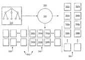
- FIG. 1is a block diagram illustrating various network elements located within health care (medical) information system.
- FIG. 2Ais a block diagram illustrating a representation of internal software components and a communications protocol interface residing within the vital signs measuring (VSM) device and the host 110 c , as shown in FIG. 1 .
- VSMvital signs measuring
- FIG. 2Bis a block diagram that illustrates receiving information from another network element through the communications interface.
- FIG. 2Cis a block diagram that illustrates receiving information through the communications interface.
- FIG. 2Dis a block diagram illustrating a structure of the information that is output from the interchange layer when transmitting from the communications interface.
- FIG. 2Eis a block diagram illustrating an exchange of rendezvous protocol communications to establish a connection between a VSM device and a host network element.
- FIG. 3Ais a block diagram illustrating a structure of the information that constitutes a medical object management protocol (MOMP) message.
- MOMPmedical object management protocol
- FIG. 3Bis a block diagram illustrating an MOMP message exchange between a host device and a VSM device including a request type of MOMP message.
- FIG. 3Cis a block diagram illustrating an MOMP message exchange between a host device and a VSM device including a command type of MOMP message.
- FIG. 3Dis a block diagram illustrating an MOMP message exchange between a host device and a VSM device including a status type of MOMP message.
- FIG. 3Eis a block diagram illustrating an MOMP message exchange between a host device and a VSM device including an event type of MOMP message.
- FIG. 3Fis a block diagram illustrating a keep alive communications transmitted between network elements.
- FIG. 3Gis a block diagram illustrating a structure of the information that constitutes a data object message.
- FIG. 4Ais a block diagram illustrating an structural arrangement of software in accordance with an embodiment of the invention.
- FIG. 4Bis a block diagram that illustrates a path of execution through an embodiment of WACP CPI software that receives, processes and routes an incoming request type of WACP message, in accordance with the invention.
- FIG. 4Cis a block diagram that illustrates a path of execution through an embodiment of WACP CPI software that transmits a response type of WACP message, in response to receiving the request type of WACP message of FIG. 4A .
- FIG. 5Aillustrates a system that includes a software generator that is configured to input a set of directives and to output source code in response to the set of directives.
- FIG. 5Bis a block diagram illustrating the different configurations of WACP CPI software that are installed onto a plurality of interoperating network elements.
- FIG. 5Cillustrates a flow chart for designing and evolving, and automatically generating and certifying software that implements a WACP communications protocol interface (CPI).
- CPIWACP communications protocol interface
- FIG. 5Dillustrates portions of a global set of directives being built into different configurations.
- FIG. 6Aillustrates a set of directives that define a plurality of extended modules and that are encoded in Extensible Markup Language (XML).
- XMLExtensible Markup Language
- FIG. 6Billustrates the set of directives of FIG. 6A including XML element tags that are nested one level below the ⁇ FAMILY_NIBP> element.
- FIG. 6Cillustrates XML element tags that are located one level below the ⁇ MESSAGES> element of the ⁇ FAMILY_NIBP> element of the set of directives of FIG. 6A .
- FIG. 6Dillustrates XML element tags that are located one level below the ⁇ CNIBPCSTD_DEFINITION> element of the ⁇ FAMILY_NIBP> element of the set of directives of FIG. 6A .
- FIG. 6Eillustrates some of the XML element tags that are located one level below the ⁇ CNIBPDSTD_DEFINITION> element of the ⁇ FAMILY_NIBP> element of the set of directives of FIG. 6A .
- FIG. 1is a block diagram illustrating various network elements located within health care (medical) information system 100 .
- the network elementsincluding host (server) computers 110 A- 110 C, vital signs measuring devices (VSMD) 140 A- 140 Y, electrocardiogram (ECG) devices 150 and other devices 160 , constitute nodes within a network and perform a variety of different functions within the system 100 .
- the host computers 110 A- 110 Care typically stationary (non-mobile) devices that accommodate a variety of optional hardware including hard disk drives, RAM memory cards and communication interface hardware to support Ethernet, WIFI, USB and serial communications interfaces with other network elements, for example.
- Vital signs measuring devices (VSMD) 140 A- 140 Yare devices that are used by operators to perform various vital sign related physiological measurements of a patient.
- a VSMD 140 A- 140 Ycan measure systolic and diastolic pressure, mean arterial pressure, pulse rate, temperature and pulse oximetry (SpO2) of adult and pediatric patients.
- a VSMD 140 A- 140 Ycan typically communicate to other devices, including a server computer 110 A- 110 C, via an RS-232 serial interface, a universal serial bus (USB) interface or via WiFi (wireless) (802.11) communications interface.
- RS-232 serial interfaceRS-232 serial interface
- USBuniversal serial bus
- WiFiwireless
- the VSMD 140 A- 140 Yis a Welch Allyn Spot LXi vital signs measuring device (VSMD).
- the Spot LXi VSMD 140 A- 140 Noptionally uses a wireless adapter 158 a - 158 n to wirelessly (WiFi) communicate via 802.11 communications channel 156 a - 156 n to another 802.11 type of communicating device, such as to the host computer 110 C, via a WiFi gateway 170 .
- the Spot LXi VSMD 140 Yalso communicates via RS-232 serial communications channel 142 to host computer 110 B.
- an ECG measurement device 150can communicate via a USB communications channel 144 to the host computer 110 B or communicate via RS-232 serial communications channel 146 to host computer 110 C.
- another device 160can communicate via a USB communications channel 148 to the host computer 110 C.
- the host computer 110 Bcan also communicate with another remotely located host computer 110 A via an Internet communications channel 152 or communicate with another host computer 110 C, via an Ethernet local area network communications channel 154 .
- the host computer 110 Bis directly connected to a database 130 that functions as a repository of data.
- the database 130stores and processes data captured and processed by the system 100 . Much of the data of the medical information system is defined and structured to represent numerous measurements of human physiology for a population of patients.
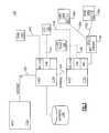
- FIG. 2Ais a block diagram illustrating a representation of internal software components and a communications protocol interface residing within the vital signs measuring device (VSMD) and the host computer 110 c , as shown in FIG. 1 .
- VSMDvital signs measuring device
- the representation of the communications interface 210includes a layering (stack) of communications protocols, also referred to herein as a protocol stack, that is exercised between the VSMD 140 N and the host computer 110 c .
- Each communications protocolis implemented as executing software within the communications protocol interface 210 for each network element, such as the VSMD 140 N and the host computer 110 C, and operates in accordance with a communications protocol interface (CPI) specification, also referred to as a communications interface specification (not shown) and is employed to assist with the communication of information, including data that is acquired (collected), stored and processed by each network element of the system 100 .
- CPIcommunications protocol interface
- a communications interface specificationis a tangible, such as a written, printed or digitally encoded description of a communications interface.
- a communications interfaceis also referred to herein as a communications protocol interface (CPI) and a communications interface specification is also referred to as a communications protocol interface (CPI) specification.
- CPIcommunications protocol interface
- CPIcommunications protocol interface
- the lower three protocol layers 210 A- 210 Cidentified as 802.11 ( 210 A), internet protocol (IP) 210 B and transport connection protocol (TCP) 210 C are exemplary, and are standard and well known communications protocols that collectively constitute a lower portion of the protocol stack 210 , also referred to as a lower protocol stack 210 A- 210 C.
- the lower three protocol layers 210 A- 210 Care employed to support and carry the (3) upper protocol layers, respectively the Interchange 210 D, Rendezvous 210 E and MOMP 210 F protocol layers, and are designed in accordance with the invention.
- this specific lower protocol stack 210 A- 210 Cis not required, and can be modified in various ways to practice the invention.
- Other communications protocols, or combinations of communications protocolscan be substituted for and/or combined with the protocols 210 A- 210 C in various ways to support and carry the upper protocol layers 210 D- 210 F.
- the Interchange protocol layer 210 Dalso referred to herein as the Exchange layer or Interchange layer 210 D, resides on the session layer of the Open Systems Interconnection (OSI) reference model and is employed to carry the Rendezvous protocol 210 E or the MOMP 210 F protocol.
- OSIOpen Systems Interconnection
- the application software 220 of the host computer 110 Cis configured to implement the upper protocol stack 210 D- 210 F while the operating system software 222 of the host computer 110 C is configured to implement the lower protocol stack 210 A- 210 C.
- the application software 230 of the VSMD 140 nis configured to implement the upper protocol stack 210 D- 210 F while the operating system software 232 of the VSDN 140 n is configured to implement the lower protocol stack 210 A- 210 C.
- other network elementstypically implement the protocol stack in the same manner as described above.
- FIG. 2Bis a block diagram that illustrates transmitting information from a first network element to a second network element through the communications interface 210 .
- the application layer 210 Ginitiates a transfer of information 212 g , typically in the form of function call parameters, to either the Rendezvous 210 E or the MOMP 210 F protocol layers.
- the function call parametersinclude a pointer to a buffer of information to be transmitted via the communications interface 210 .
- the next receiving protocol layereither the Rendezvous 210 E or the MOMP 210 F protocol layer, according to the circumstance, further transfers the information 212 e or 212 f , to the Interchange layer 210 D.
- the information 212 e or 212 fis input into the Interchange layer 210 D from either from the Rendezvous 210 E or the MOMP 210 F protocol layers, respectively.
- the information that is input from the Rendezvous 210 E layer 212 eis typically involved with an establishment or termination of a connection with the second network element.
- the information that is input from the MOMP 210 E layer 212 eis typically involved with the use of a connection with the second network element that was previously established by the Rendezvous 210 E layer.
- the interchange layer 210 Dinputs the information 212 e or 212 f and outputs information 212 d to the lower protocol stack 210 A- 210 C.
- the information transfer 212 dis structured as an Interchange envelope that surrounds and includes either the information 212 e or 212 f , depending upon the source of the information 212 e or 212 f that is input into and processed by the Interchange layer 210 D.
- information transfer 212 dincludes the information 212 e in the circumstance where the information 212 e is received and processed by the interchange layer 210 D, or includes the information 212 f in the circumstance where the information 212 f is received and processed by the interchange layer 210 D.
- the lower protocol stack 210 A- 210 Cinputs the information 212 d and outputs information 212 a for communication via a communications channel (not shown) to the second network element.
- the information 212 aincludes the information 212 d plus protocol information added by the software implementing the lower protocol layers 210 A- 210 C.
- FIG. 2Cis a block diagram that illustrates receiving information by the first network element from the second network element through the communications interface 210 .
- the lower protocol stack 210 A- 210 Cinputs information 214 a transmitted from the second network element via the communication channel and related hardware (not shown).
- the lower protocol stack 210 A- 210 Cprocesses the information 214 a and outputs information 214 d to the interchange layer 210 D.
- the interchange layer 210 Dinputs and processed the information 214 d and outputs (routes) information 214 e to the Rendezvous layer 210 E or information 214 f to the MOMP layer 210 F, depending upon to which layer the information 214 d is addressed to.
- the information transfer 214 dis structured as an Interchange envelope that surrounds and includes information addressed to either Rendezvous layer 210 E or the MOMP layer 210 F layer.
- the interchange layer 210 Dremoves information constituting its envelope.
- the Rendezvous 210 E and the MOMP 210 F protocol layerseach input and process and information received from the interchange protocol layer 210 D.
- FIG. 2Dis a block diagram illustrating a structure 220 of the information 212 d that is output from the interchange layer 210 D when transmitting from the communications interface 210 .
- this structure 220is also referred to herein as a large version of an Interchange envelope 220 , session envelope 220 , or a session wrapper 220 .
- the structure 220is divided into a plurality of portions, referred to herein as fields.
- the fieldsinclude a session preamble field 222 , packet length field 224 , a port/application identifier field 226 , sequence number 228 , a UUID field 230 , a data length field 232 a data buffer field 234 and a header cyclic redundancy check (CRC) field 236 .
- a session preamble field 222packet length field 224 , a port/application identifier field 226 , sequence number 228 , a UUID field 230 , a data length field 232 a data buffer field 234 and a header cyclic redundancy check (CRC) field 236 .
- CRCheader cyclic redundancy check
- the session preamble field 222is configured to delimit the structure 220 and includes a unique sequence of binary values.
- the packet length field 224indicates the length of the entire structure 220 in units of bytes.
- the port/application identifier fieldidentifies a port number that is associated with an application type.
- the application typecan identify a Rendezvous or WACP application type.
- the sequence number field 228stores a unique identifier for each portion of the structure when the structure is divided into portions in response to limited buffer capacity employed while communicating the structure 220 .
- the UUID field 230stores an identifier for the structure 220 so that another response communication received by the Interchange layer 210 D can be associated with the structure 220 .
- the data length field 232stores a length of the data buffer field 234 , preferably in units of bytes.
- the data buffer field 234stores data included within (carried by) the structure 220 .
- the CRC field 236stores a cyclic redundancy check (CRC) value computed for the entire structure 220 .
- the structure 240illustrates a small version 240 of the interchange envelope.
- the structure 240includes a subset of the fields of the large version 220 .
- the fieldsinclude a session preamble field 222 , packet length field 224 , a port/application identifier field 226 , a data buffer field 234 and a header cyclic redundancy check (CRC) field 236 .
- the small versionexcludes the sequence number 228 , a UUID field 230 , and a data length field 232 .
- the small version 240 of the interchange envelopecan be employed by the interchange layer 210 D for information that is small enough to fit within the capacity of buffers employed across the connection while communicating the structure 240 .
- the interchange envelope 240is not required to be divided (decimated) and sequenced into smaller portions that fit within one or more buffers of limited size residing between end points of the connection.
- FIG. 2Eis a block diagram illustrating an exchange of Rendezvous communications protocol to establish a connection between a VSM device 140 n and a host 110 c network element.
- the rendezvous protocol layerinitiates a transmission of a connection request communication 252 that is addressed to the host 110 c .
- the connection request 252is included within an Interchange envelope 220 , 240 and transmitted from the VSM device 140 n to the host 110 c via the interchange protocol layer 210 D and the lower protocol stack 210 A- 210 C operating within the VSM device 140 n .
- the data buffer field 234 of the interchange envelope 220includes (carries) a “RNDZConnect” string to identify it as a rendezvous protocol connection request message.
- the rendezvous protocol layer 210 E operating within the host 110 creceives the connection request communication 252 via the lower protocol stack 210 A- 210 C and the Interchange protocol layer 210 D that are operating within the host 110 c .
- the port/application identifier field 226indicates the rendezvous protocol layer as the application type addressed by the connection request communication 252 .
- the host computer 110 cis addressed via the protocols of the lower protocol stack 210 A- 210 C.
- connection accept communication 254is included within an interchange envelope 220 , 240 and transmitted from the host 110 c to the VSM device 140 n via the Interchange protocol layer 210 D and the lower protocol stack 210 A- 210 C implemented by software that is operating within the host 110 c.
- the port/application identifier field 226 of the communication 254indicates the rendezvous protocol layer as the application type addressed by the connection request communication 252 .
- a rendezvous connectionis now established.
- the VSM device 140 ntransmits an encryption key request communication 256 to the host 110 c .
- the host 110 cresponds by transmitting an encryption key communication 258 that includes an encryption key, also referred to as a session key.
- the clientUpon receiving the encryption key, the client transmits a start WACP process request communication 260 to the host 10 c .
- the host 110 cresponds by executing an instance of a WACP process (not shown) and by transmitting a host ready communication 262 .
- the VSM device 140 nreceives the host ready communication and transfers control to a WACP process operating within the VSM device 140 n (not shown).
- the Rendezvous connectionterminates when a rendezvous connection termination communication is transmitted by the host 110 c .
- the exchange of communications between the VSM device 140 n and the host 110 care independent of the type of communications channel (not shown) that is employed for communication between the VSM device 140 n and the host 110 c.
- FIG. 3Ais a block diagram illustrating a structure of the information that constitutes a medical object management protocol (MOMP) message 300 .
- the MOMP message 300resides within and is carried by the data buffer field 234 of the interchange protocol message 220 , 240 .
- the structure of the MOMP message 300is divided into a plurality of portions, referred to as fields.
- the fieldsinclude a message identifier field 302 , a message size field 304 , a message encryption field 306 , an object buffer field 308 and a cyclic redundancy check (CRC) field 310 .
- CRCcyclic redundancy check
- the message identifier field 302includes a set of values that identify and classify the type of the MOMP message 300 .
- the message length field 304indicates the length of the entire MOMP message 300 , preferably in units of bytes.
- the message encryption field 306includes values that indicate whether any encryption of the MOMP message 300 is being employed and if true, what type of encryption is being employed.
- the object buffer field 308stores data that represents a serialized object.
- the serialized objectcan be a set of physiological data acquired by a particular network element.
- the CRC field 310stores a cyclic redundancy check (CRC) value computed for the entire structure 300 .
- CRCcyclic redundancy check
- the message identifier field 302includes (3) sub-fields that each represent one type classification for the MOMP message 300 .
- Each type classificationrepresents one tier of a (3) tier classification scheme.
- the first sub-field 312stores a value representing a first (highest tier) classification, also referred to as a family classification.
- the first classificationcan identify a particular module having and associated set of physiological data and message types.
- the datacan be physiological data types associated with blood pressure, for example.
- the first classificationidentifies a module having an identifier equal to the text string “FAMILY_NIBP”.
- the moduleacquires and communicates a set of blood pressure related physiological data types.
- the identifier “FAMILY_NIBP”is mapped to a unique value that is stored as the first classification, into the first sub-field, for the MOMP message 300 that is associated with the FAMILY_NIBP module.
- Other text string identifiersare used to identify modules other than the FAMILY_NIBP module.
- the second sub-field 314stores a value representing a second (middle tier) classification, also referred to as a genus classification.
- the second classificationcan identify a set of one or more attributes of the FAMILY_NIBP module that is identified by the first classification.
- the attributesinclude types of MOMP messages that are transmitted and/or received by the FAMILY_NIBP module.
- the second classificationidentifies a request type of MOMP message that is indicated by a text string identifier “Gn_Request”.
- the “GnRequest’ identifieris mapped to a unique value that is stored into the second sub-field and indicates that the MOMP message is a request type of MOMP message 300 (See FIG. 3B ).
- a request type of MOMP messageis also referred to herein as being a generic type of MOMP message.
- a generic type of MOMP messagegenerally characterizes processing associated with an MOMP message but does not provide sufficient information for software to specifically process each byte of the MOMP message. Generally, all three classifications are required to provide sufficient information for software to process each byte of the MOMP message 300 .
- the third sub-field 316stores a value representing a third classification (lowest tier), also referred to as a species classification.
- the third classificationcan identify a set of one or more additional attributes of the module identified by the first classification and of the MOMP message type identified by the second classification.
- the third classificationidentifies a particular get blood pressure type of request MOMP message that is indicated by a text string identifier “GET_BP”.
- the “GET_BP” identifieris mapped to a unique value that is stored into the third sub-field and indicates that the MOMP message is a particular “GET_BP” type of request type of MOMP message 300 .
- the particular “GET_BP” type of a request type of MOMP messagehas a pre-defined byte sequence that provides sufficient information for software to specifically process each byte of the MOMP message 300 .
- a GET_BP type of MOMP messageis also referred to herein as being a specific type of MOMP message.
- a device data sheet(See FIG. 6A ).
- a device data sheet(DDS) is employed as input to a software generator (See FIG. 5A ) that outputs source code that directs the execution of a directive dependent portion of a communications interface 210 , implemented with software that executes on a network element.
- the device data sheetdefines a module that includes defined data and operations associated with the defined data to be processed by a particular device.
- the operations associated with the dataare expressed in the form of generic and specific MOMP messages that are configured to perform operations upon the defined data.
- the DDSis used to configure at least a portion of the software that implements a WACP communications interface.
- a GET_BP messagerequests the transmission of blood pressure data from the network element receiving the GET_BP message, to the network element transmitting the GET_BP message.
- the requested blood pressure datacan be transmitted by the network element receiving the GET_BP message via transmission of a PUT_BP message to the network element transmitting the GET_BP message.
- FIG. 3Bis a block diagram illustrating an MOMP message exchange between a host device and a VSM device including a request type of MOMP message.
- the host device 110 ctransmits an MOMP request communication 322 to receive blood pressure measurement information from the VSM device 140 n .
- the request communication 322includes an MOMP message with a message identifier field including the sub-field values represented by the symbols FAMILY_NIBP, Gn_Request and GET_BP respectively.
- the first classification identifier FAMILY_NIBPidentifies a module that includes a set of measured blood pressure related data.
- the second value Gn_Requestidentifies a request type of MOMP message 300 that is defined in association with the FAMILY_NIBP object.
- the third value GET_BPidentifies a specific structure and representation of data that is requested by the host 110 c via the Gn_Request type of message.
- the host 110 cis requesting that the VSM device 140 n transmit a response type of MOMP communication, including an instance of the specific structure and representation of data, to the host 110 c in response to the request communication 322 .
- the VSM device 140 ntransmits an MOMP response communication 324 including the instance of the specific structure and representation of data associated with the GET_BP specific (species) classification.
- the response communication 324includes an MOMP message where the message identifier field includes classifications (sub-field values) represented by the symbols FAMILY_NIBP, Gn_Response and PUT_BP respectively.
- the first value(FAMILY_NIBP) identifies the module that includes the requested set of measured blood pressure related data.
- the second value(Gn_Response) identifies a response type of MOMP message that is defined in association with the FAMILY_NIBP module.
- the third value(PUT_BP) identifies a specific structure and representation of data that is being transmitted by the VSM device 140 n via this (Gn_Response) type of MOMP message 300 .
- the VSM device 140 nis unable to transmit a response type of MOMP message communication 324 in order to respond to receiving the request type of MOMP communication 322 .
- the VSM device 140 ninstead transmits a trap type of MOMP communication 326 in response to the request type of MOMP communication 322 .
- the trap communication 326includes a trap type 330 of MOMP message 300 .
- the trap type of MOMP message 330is structured like a generic MOMP message 300 that includes an error object. Like other generic MOMP messages 300 , the trap type of MOMP message has a message identifier field 302 including the first, second and third classifications (sub-field values) represented by the text string identifiers “FmTRAP”, “GnError” and “SpError” respectively.
- the first identifierindicates the module within the VSM device 140 n that is responding to the original communication 322 transmitted from the host computer 110 C.
- the original communication 322was addressed to the (FmNIBP) module of the VSM device 140 n , but the (FmNIBP) module was unable to perform actions associated with the original communication 322 and as a result, transferred control to the FmTRAP module of the VSM device 140 n in order to respond to the communication 322 .
- the second classification identifier(GnError) identifies an error type of message that is defined in association with the (FmTRAP) module.
- the third classification identifier(SpError) identifies a type of error has occurred. This type of error is referred to herein as a “NAK”, meaning a non-acknowledgement type of trap MOMP message.
- a third value(SpNone) can identify an ‘ACK”, meaning an acknowledgement type of trap MOMP message.
- the trap message 330includes an error object 340 that is also referred to herein as a trap object 340 .
- the error object 340resides within the object buffer field 308 of the MOMP message 300 and includes error identification data.
- the error identification datadescribes one or more errors resulting from actions or attempted actions of the VSM device 140 n in response to receiving the original communication 322 .
- the structure of the error object 340is divided into a plurality of fields.
- the fieldsinclude an object identifier field 332 , also referred to as a CLSID field 332 , an object size field 334 , an object version field 336 , a bit field 338 , an object payload field 342 , and an object CRC field 344 .
- the object payload field 342is further divided into a plurality of fields.
- the fieldsinclude a message size field 346 , a message identifier field 302 , an error opcode field 348 , a textual error description field 356 , an extended error size field 358 and an extended error information field 360 .
- the message size field 346is expressed in units of bytes.
- the message identifier field 302identifies the MOMP message 300 included within the original communication 322 that the error object is responding to. Hence, the message identifier field 302 includes the identifiers (FAMILY_NIBP, Gn_Request and GET_BP) that are stored into the request type of MOMP message 300 included within the original communication 322 .
- the error opcode field 348stores a generic error code that is provided by the module that the original communication 322 was transmitted to. Hence, the error opcode field 348 is provided by the FAMILY_NIBP module.
- the textual error description field 356is text that is also supplied by the module that the original communication 322 was transmitted to. Hence, the textual error description field 356 is provided by the FAMILY_NIBP module.
- the host computer 110 cis not required to maintain an exhaustive list of error definitions associated with network elements that it may later communicate with.
- the extended error information field 360is provided by the VSM device 140 n itself and is device specific, as opposed to being generic information originating from the FAMILY_NIBP module directives and/or the WACP communications protocol interface (CPI) software, also referred to as WACP communications interface software.
- the extended error size field 358indicates the size of the extended error information field 360 , preferably in units of bytes.
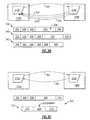
- FIG. 3Cis a block diagram illustrating an MOMP message exchange between a host device 110 c and a VSM device 140 n including a command type of MOMP message 300 .
- the host device 110 ctransmits a communication 362 including a command type of MOMP message, also referred to as a command communication 362 or a command message 362 , to the VSM device 140 n.
- a command type of communication 362directs that a specific action be performed by the network element receiving the command communication 362 .
- the command communication 362includes a command type of MOMP message 300 having a message identifier field including the sub-field values represented by the text string identifiers (FmNIBP), (GnCommand) and (START_NIBP) respectively.
- the first classification identifier value FmNIBPidentifies a module that includes a set of measured blood pressure related data.
- the second classification identifier value GnCommandidentifies a generic GnCommand type of MOMP message that is defined in association with the FmNIBP module.
- the GnCommandis a command type of MOMP message.
- the third value START_NIBPidentifies a specific command type of MOMP message that is defined within the GnCommand second classification of the FmNIBP module.
- the START_NIBP command 362is transmitted by the host 10 c to the VSM device 140 n as a GnCommand type of MOMP message associated with the FmNIBP module.
- the host 110 cis directing that the VSM device 140 n initiate a start of a blood pressure measurement cycle via the START_NIBP sub-field.
- the VSM device 140 ntransmits an MOMP trap type of communication 364 including a trap type of MOMP message having a message identifier field including the classifications (sub-field values) represented by the text string identifiers “FmTRAP”, “GnError” and “SpNone” respectively.
- the third classification identifier value SpNoneidentifies an ‘ACK”, meaning an acknowledgement type of trap message.
- the acknowledgementindicates a successful completion of the performance of the START_NIBP command, namely the successful initiation of a start of a blood pressure measurement cycle by the receiving network element.
- the third valueequals SpError to indicate an ‘NAK”, meaning a non-acknowledgement type of trap message.
- the non-acknowledgementindicates a non-successful completion of the performance of the command, namely the non-performance of the initiation of a start of a blood pressure measurement cycle by the receiving network element.
- FIG. 3Dis a block diagram illustrating an MOMP message exchange between a host device 110 c and a VSM device 140 n including a status type of MOMP message.
- the VSM device 140 ntransmits a communication 372 including a status type of MOMP message 372 , also referred to as a status communication 372 or status message 382 , to the host device 110 c .
- a status type of communication 372provides information to a network element (host) 110 c receiving the communication 372 .
- the status communication 372includes a static type of MOMP message 300 having a message identifier field including the sub-field values represented by a first classification text string identifier, such as “FmNIBP” for example, a second classification text string identifier “GnStatus” and a third classification identifier, such as “REPORT_BP” for example.
- the status communication 372includes a status type of MOMP message 300 having a message identifier field 302 including the sub-field values representing the first, second and third classification identifiers as (FmNIBP), (GnStatus) and (REPORT_BP) respectively.
- the “FmNIBP” identifierindicates the module that is transmitting the status communication 372 .
- the second classification identifierequal to GnStatus, indicates that the message is a status type of MOMP message.
- the first classification identifier FmNIBPalso indicates a module that includes a set of measured blood pressure related data.
- the second classification identifier GnStatusidentifies a GnStatus type of MOMP message that is defined in association with the FmNIBP module.
- the GnStatusis a status type of MOMP message.
- the third value REPORT_BPidentifies a specific type of status information that is included within the GnStatus classification.
- a status message 372is transmitted periodically, over time.
- a WACP communications software modulecan be configured to transmit a status message 372 to a particular destination every 10 minutes.
- the host computer 110 Cresponds by transmitting a trap communication 374 that indicates an acknowledgment or a non-acknowledgment of the status communication 372 (See FIG. 3B ).
- a status type of MOMP messagemay or may not be associated with a particular module.
- FIG. 3Eis a block diagram illustrating an MOMP message exchange between a host device 110 c and a VSM device 140 n including an event type of MOMP message. As shown, the VSM device 140 n transmits a communication 382 including a event type of MOMP message 382 , also referred to as a event communication 382 or event message 382 , to the host device 110 c.
- a communication 382 including a event type of MOMP message 382also referred to as a event communication 382 or event message 382
- An event type of communication 382provides information to a network element (host) 110 C receiving the communication 382 .
- the event communication 382includes a event type of MOMP message having a message identifier field including the sub-field values represented by a first classification text string identifier such as “FmPrinter” for example, a second classification text string identifier “GnEvent” and a third classification text string identifier, such as “HW_MOD_CONNECT”, for example.
- the first classification identifier FmPrinteridentifies a particular module that interfaces with a printer.
- the second classification identifier GnEventidentifies a GnEvent type of MOMP message classification that is defined in association with the FmPrinter module.
- the GnEventis an event type of MOMP message.
- the third classification identifier value HW_MOD_CONNECTidentifies a specific type of event information that is included within the GnEvent classification. For example, the HW_MOD_CONNECT event identifies the occurrence of a hardware module being connected with a printer device associated with the FmPrinter module.
- an event type of MOMP messagemay or may not be associated with a particular module.
- an event message 382is transmitted in response to an occurrence of an event.
- a WACP communications software modulecan be configured to transmit an event message 382 upon the occurrence of an event, such as an event represented by the HW_MOD_CONNECT symbol, where hardware is being connected with a printer device associated with the FmPrinter module.
- the host computer 110 Cresponds by transmitting a trap communication 384 that indicates an acknowledgment or a non-acknowledgment of the status communication 372 (See FIG. 3B ).
- FIG. 3Fis a block diagram illustrating a keep alive communications 392 , 394 transmitted between network elements 110 c , 140 n .
- a keep alive communication 392 , 394indicates to the receiving network element that the sending network element 110 c , 140 n is active (alive) with respect to communicating over a particular connection between the network elements 110 c , 140 n . If a receiving network element that expects to receive a keep alive communication, does not receive a keep alive communication over a pre-determined period of time, then an inference can be made that the sending network element 110 c , 140 n is no longer available to communicate.
- a keep alive communication 392 , 304includes a keep alive type of MOMP message 390 that is also referred to a keep alive message 390 .
- the keep alive message 390includes an identifier field 302 , a message size field 304 , a message encryption field 306 and a cyclic redundancy check (CRC) field 310 .
- the keep alive message 390excludes an object buffer field 308 .
- the keep alive message 390has a message identifier field 302 including the sub-field values represented by a first classification text string identifier “FmCONNECTION”, a second classification text string identifier equal to either “GnREQUEST”, “GnRESPONSE”, “GnCOMMAND”, “GnCONFIG” and a third classification text string identifier equal to either “SpKEEPALIVE”, “SpSHUTDOWN”, “SpKEEPALIVEON” or “SpKEEPALIVEOFF”.
- the first classification identifier FmCONNECTIONidentifies a particular module associated with a connection between network elements.
- the second classification identifieridentifies an associated MOMP type of message.
- the third classification identifier valueindicates the particular function of the keep alive message 390 .
- the third classificationequals “SpKEEPALIVE”, it indicates to the receiving network element 140 n , 110 c that the sending network element 110 c , 140 n is active (alive) with respect to communicating over a particular connection between the network elements 110 c , 140 n . If the third classification identifier equals “SpSHUTDOWN”, it indicates to the receiving network element 140 n , 110 c that the sending network element 110 c , 140 n is initiating a shutdown of the connection between the network elements 110 c , 140 n.
- the third classificationequals “SpKEEPALIVEON”, it indicates to the receiving network element 140 n , 110 c that the sending network element 110 c , 140 n is requesting that the receiving network element periodically transmit keep alive messages 390 . If the third classification equals “SpKEEPALIVEOFF”, it indicates to the receiving network element 140 n , 110 c that the sending network element 110 c , 140 n is requesting that the receiving network element does not periodically transmit keep alive messages 390 .
- FIG. 3Gis a block diagram illustrating a structure of the information that constitutes a data object message 396 .
- a data object message 396is carried within the data buffer field 234 of an Interchange envelope 220 , 240 in the same manner as an MOMP message 300 .
- the data object message 396substitutes for an MOMP message 300 within the data buffer field 234 .
- No MOMP messageis used to carry the data object message 396 .
- the structure of the data object 396is divided into a plurality of fields like that described for an error object 340 (See FIG. 3B ).
- the data objectincludes an object identifier field 332 , also referred to as a CLSID field 332 , an object size field 334 , an object version field 336 , a bit field 338 , an object payload field 342 , and an object CRC field 344 , like that shown in FIG. 3B .
- the data objectis referred to as being serialized data object.
- Transmitting a data object 396 that is not enclosed within a MOMP message 300reduces a byte count required per transmission and is more efficient with respect to bytes required to transmit data.
- data object messages 396can be used for streaming of data between network elements.
- FIG. 4Ais a block diagram illustrating a structural arrangement of WACP CPI software in accordance with an embodiment of the invention.
- the WACP CPI software 414 a , 414 bis configured to implement the upper protocol stack 210 D- 210 F.
- the operating system software 412us configured to implement the lower protocol stack 210 A- 210 C.
- the WACP CPIis divided into a core portion and a non-core (extensible) portion.
- the core portion of the WACP CPIfunctions as a generic framework that specifies functionality including connection establishment and termination, encryption and generic message types, including the request, response, command, status and error types of MOMP messages.
- the non-core (extensible) portion of the WACP CPIallows for the addition of modules including associated data and messages. The modules extend the functionality of the core portion of the WACP CPI.
- directivesare employed to define modules, to define data included within the module and to define specific structures of request, response, command, status and error types of MOMP messages associated with the defined module.
- the non-core portion of the WACP CPIenables the functionality of the core portion to be supplemented and customized to accommodate a particular applications.
- software that is configured to implement the WACP CPIis divided into a core portion 414 a and a non-core (extensible) portion 414 b .
- the core portion 414 a of the WACP CPI softwareis configured to implement WACP CPI functions regardless of what modules are or are not defined within a particular WACP CPI software configuration, and implements functionality including connection establishment and termination, encryption and generic message types, including the request, response, command, status and error types of MOMP messages.
- the non-core portion 414 b of the WACP CPI softwareimplements the non-core supplemental and customizable functionality in the form of modules.
- modulescan be added via directives that define module related functionality including operations upon module associated data and messages.
- the non-core portion of the WACP CPI softwaresupplements the functionality of the core portion of the WACP CPI and of the WACP CPI as a whole.
- the core portion of 414 a of the WACP CPI softwareis configured to interface with an operating system 412 . Both the core and non-core portions of the WACP CPI software can interface with application software 416 .
- the non-core (supplemental) features of the WACP CPI softwareenables customization of the implementation of the WACP CPI itself to accommodate particular communications requirements required by the operation of a particular set of one or more network elements.
- a portion of the WACP CPI designcan be configured to accommodate the communication of particular types and structures of data, such as types of physiological data that are required by a particular set of network elements.
- each network elementsuch as a VSM device 140 n
- CPIWACP communications protocol interface
- individual network elementscan be uniquely and efficiently configured to communicate a portion, whether a small or large portion, of a vast amount and variety of universally defined device independent data (information) within a network that is configured to acquire, communicate and process such data.
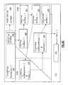
- FIG. 4Bis a block diagram that illustrates a path of execution through an embodiment of WACP CPI software 414 that receives, processes and routes an incoming request type of WACP message, in accordance with the invention.
- the WACP softwareis shown as residing within a VSM device 140 .
- the WACP softwarecan also reside in any network element that is configured to employ the WACP communications protocol interface (CPI), including for example, a host computer 110 c and/or other types of devices configured to interoperate with WACP enabled network elements.
- CPIWACP communications protocol interface
- the core portion 414 a of the WACP CPI software 414is included within a plurality of software objects 424 - 426 and the non-core portion 414 b - 414 c of the software 414 is included within a plurality of software objects 422 , 428 - 432 .
- the software objectsare developed from the C++ programming language source code, also referred to as C++ code and/or source code. Each software object encapsulates instructions and data. The instructions of a software object reside within its methods, which are functions residing inside of the software object.
- software objectscan be developed from other types of source code, such as for example, the source code of the C, C# (C sharp) or Java programming languages.
- a WACP message 390was transmitted to the VSM device 140 n from another network element and is received and buffered by the operating system 412 .
- the WACP message 390is an MOMP request type of message having a first, second and third message classification and that is enclosed within an interchange envelope 220 .
- the WACP CPI software 414is configured to route, process and deliver the message 390 to an appropriate location within the application software 416 provided that the message 390 passes various integrity checks performed by the WACP CPI software 414 .
- the processing and delivery of the message 390will be performed according to various attributes of the message 390 , including the first, second and third message classifications stored within the message 390 .
- the application software 416Upon delivery of the message 390 to a particular location within the application software 416 , the application software 416 will decide if and how to respond to the delivery of the message 390 .
- a path of execution 438 for receiving, processing and routing the WACP message 390is shown.
- the path of execution 438travels through the operating system 412 , through the WACP CPI software 414 and into the application software 416 .
- the WACP CPI software 414is included within a set of software objects 422 - 432 that collectively receive, process and route the message to the application software 416 .
- Portions of the application software 416are also included within a set of software objects 432 - 434 .
- the operating system 412is implemented as a Microsoft Windows 32 bit operating system, such as Windows XP.
- the operating system 412 and its associated software including its device and network driversare configured to implement the lower protocol stack 210 A- 210 C of the WACP CPI (See FIG. 2B ).
- the WACP CPI software 414 and its associated software objects 422 - 236implement the upper protocol stack 210 D- 210 G.
- the upper protocol stack 210 D- 210 G of the WACP CPI software 414receives communications from the lower protocol stack 210 A- 210 C of the operating system 412 in the following manner.
- a RecvMsg( ) method of an CEthCommSvr object 420calls a recv( ) function residing inside of a ws2 — 32.dll dynamic link library (DLL) to receive and queue a message 390 message buffered inside of the operating system 412 .
- the ws2 — 32.dllis provided by Microsoft to interoperate with its Windows operating systems including Windows XP, Windows 2000, Windows NT and Windows Server 2003, for example.
- the RecvMsg( ) method of the CEthCommSvr object 420sets a semaphore to indicate the availability of communications data received from the lower protocol stack 210 A- 210 C.
- the DataThread( ) method of the CWACPPres object 422executes along a thread, referred to as a message input thread, that waits on the setting of the semaphore by the RecvMsg( ) method of the CEthCommSvr object.
- the message input thread that is executing the DataThread( ) method of the CWACPPres object 422unblocks and calls the ProcessMsg( ) method (not shown) of the CWACPPres object 422 which calls 438 a the RecvMsg( ) method of the CFmRouter object 424 .
- the method (function) call 438 acauses the state of execution of the message input thread to leave CWACPPres object 422 and to enter the CFmRouter object 424 and to travel further along the path of execution 438 to process and route the buffered incoming WACP message 390 .
- the RecvMsg( ) methodextracts the first classification identifier from the message 390 and maps it to an object pointer that is an address of an instance of an CFmNIBPCom object 430 that is associated with the first (family) classification, of the message 390 .
- the RecvMsg( ) methodcalls 438 b a RecvMsgHandler( ) method residing within the instance of the CFmNIBPCom object 430 .
- the RecvMsgHandler( ) methodextracts the second (genus) classification identifier from the message 390 and maps it to a pre-registered (pRequestHandler) function pointer (not shown) and calls 438 c the (pRequestHandler) function object pointer.
- the function pointeris an address of an RxRequestWrapper( ) method residing within an instance of a CWACPApp object 426 .
- the RxRequestWrapper( ) methodis configured to process a request type of MOMP message.
- the function pointerwould store an address of a method, other than that of the RxRequestWrapper( ) method, that would be configured to process the type of message (second classification) and the type of module (first/family classification).
- the RxRequestWrapper( ) method of the CWACPApp object 426verifies that the sender of the message has successfully passed a prior authentication check and if true, calls 438 d the RecvRequest( ) method residing within an instance of the CWACPStub object.
- the RecvRequest( ) method residing within the instance of the CWACPStub object 428switches on the value of the first classification identifier (FmNIBP) and calls 438 e the RecvRequest( ) method of an instance of an CFmNIBPStub object 432 .
- FmNIBPfirst classification identifier
- NIBPextended module
- the instance of the CWACPStub object 432is available to optionally store application source code 436 in order to specify actions to be performed by the application software 416 in response to receiving the message 390 via the WACP CPI software 414 .
- the CWACPStub object 432is configured to store both WACP CPI software 414 and application software 416 .
- the objects CFmRouter 424 and CWACPApp 426are static core WACP software objects, meaning that the source code defining each of these objects is not configured to be a modifiable portion of the WACP CPI software. Hence, these objects 424 - 426 do not reside within the non-core portion of the WACP CPI and its software 414 .
- the WACP software objects CWACPPres 422 , CWACPApp 426 and CWACPStub 428are dynamic core objects, meaning that at least some of the source code included within the definition of these objects is configured to be a modifiable portion of the WACP CPI software.
- these objects 422 , 426 , 428reside within the dynamic (non-static) core portion of the WACP CPI and its software 414 .
- modifiable source codecan be assigned to different sets of objects.
- the objects CFmNIBPCom 430 and CFmNIBPStub 432are non-core WACP software objects, because the very existence of and all source code included within the definition of these objects is ( 414 c ) in response to the configuration of an additional non-core (FmNIBP) module to the WACP CPI software 414 .
- FmNIBPnon-core
- Core WACP CPI objectsare configured to be present within any foreseeable WACP CPI configuration.
- Extended WACP CPI objectsexist in response to extensions to the WACP CPI.
- the CWACPPres 422 , CFmRouter 424 , CWACPApp 426 and CWACPStub 428 objectsare core objects and the CFmNIBPCom 430 and CFmNIBPStub 432 objects are non-core (extended) objects within the WACP CPI software 414 .
- the CFmRouter 424 and CWACPApp 426 objectsare static and the CWACPPres 422 and the CWACPStub 428 objects are dynamic with respect to the source code included within them.
- All of the non-core objects, CFmNIBPCom 430 and CFmNIBPStub 432are dynamic with respect to the source code included within them.
- a stub functionis a location within the source code where an application programmer is free to add application specific source code to connect the CPI software 414 with application software 416 .
- stub functionsare also implemented as call back functions. Call back functions are intended to be called from the CPI software in response to a pre-specified event, such as the reception of a message.
- FIG. 4Cis a block diagram that illustrates a path of execution through an embodiment of WACP CPI software that transmits a response type of WACP message, in response to receiving the request type of WACP message of FIG. 4A .
- the RecvRequest( ) method of the CFmNIBPStub object 432includes application software 436 that is configured to perform actions in response to receiving the WACP message 390 .
- the application software 436 residing within the CFmNIBPStub object 432calls a SEND_RESPONSE( ) function which maps to a SendMsg( ) method residing within a instance of a CWACPApp object 426 .
- the SendMsg( ) method of the CWACPApp object 426calls the SendMsg( ) method residing within an instance of CWACPPres object 422 .
- the SendMsg( ) method of the CWACPPres object 422calls the SendMsg( ) method residing within the CFmRouter object 424 .
- the SendMsg( ) method of the CFmRouter object 424maps the first (family) classification identifier to a function pointer and calls the function pointer.
- the function pointerstores an address of a SendMsgHandler( ) method residing within an instance of the CFmNIBPCom object 430 .
- the instance of the SendMsgHandler( ) methodis configured to process the response type of MOMP message to be transmitted.
- the SendMsgHandler( ) methodswitches off the value of the second (genus) classification identifier and calls a TxMsg( ) method also residing within the same instance of the CFmNIBPCom object 430 .
- the TxMsg( )calls a function pointer that stores an address of a SendPacketWrapper( ) method residing within a instance of a CInterchange object 440 .
- the SendPacketWrapper( ) method 440compares a semaphore name to an application name and then calls a SendPacket( ) method also residing within the CInterchange object 440 .
- the SendPacket( ) methodserializes a response type of MOMP message and calls a SendMsg( ) method residing inside of an instance of a CEthCommSvr object 420 .
- the SendMsg( ) method of the CEthCommSvr object 420calls a send( ) function residing inside of a ws2 — 32.dll dynamic link library (DLL) to queue the message for transmission by the lower protocol layers 210 A- 210 C.
- the ws2 — 32.dllis provided by Microsoft to interoperate with its Windows operating systems including Windows XP, Windows 2000, Windows NT and Windows Server 2003, for example.
- the operating system 412exercises the lower protocol stack 210 A- 210 C to transmit the message to a destination network element.
- the WACP CPIis describable in terms of a WACP CPI specification that includes a core and an extensible portion.
- the WACP CPIis not entirely fixed and is designed to be flexible and extensible beyond what is described by the core portion of the WACP CPI specification, in order to accommodate extended (particular) functionality that is required to reside within each of various types of network elements.
- the extended functionalitycan be employed for communication of various types of data, commands and other information by each of the various types of network elements.
- the extended functionalitycan be configured to be limited and customized to particular groups of one or more network elements.
- Extended functionalityis added to the WACP CPI in the form of one or more (add on) modules.
- Each moduleis identified by the first (family) classification identifier and is further characterized by other attributes, including those indicated by the second (genus) classification identifiers and the third (species) classification identifiers that are associated with the first classification name of the module.
- Each moduleis defined from source code that specifies information, including data, procedures and messages that are associated with each respective module.
- the messagesare employed to communicate various types of information between each respective module and other network elements.
- the proceduresare employed to perform operations upon the information and to communicate the information between the module and other network elements.
- the defined datais classified into a configuration category and a data category.
- the data categoryincludes data that the network element acquires from other sources, such as from a health care patient.
- the configuration categoryincludes data specifying the configuration of the operation of the particular network element for the purpose of acquiring the data from other sources.
- FIG. 5Aillustrates a system 500 that includes a software generator program 520 that is configured to input a set of directives 510 and to output source code 540 - 560 in response to the set of directives 510 .
- the software generator program 520is referred to as application generator 520 or as AppGen 520 .
- the directivesspecify the addition of one or more modules of functionality, also referred to as extensible functionality, to the core functionality of the WACP CPI and to the software 414 that implements the WACP CPI, also referred to as a (WACP) communications software module 414 .
- the extensible functionalityis described via the directives 510 that represent the extensible portion of the WACP CPI specification.
- the directives 510specify the addition of one module that is assigned a name of “FmNIBP”.
- the core functionality of the WACP CPIis implemented as a core set of source code files 550 that include static (unrevised) core source code files 530 and dynamic (revised) core source code files 540 .
- Each module that is added to the core functionality of the WACP CPIis implemented as revisions to a subset 540 of the core set of source code files 550 and is implemented as software stored within a set of newly created source code files 560 .
- the newly created source code files 560are combined (compiled and linked) with the static source code files 530 of the core set 550 and the revised source code files 540 of the core set 550 .
- the source code files 560are combined with the core set of source code files via compiling or interpreting the source code files 560 and linking of the compiled or interpreted binary with the compiled or interpreted binary of the core set 550 of source code files using appropriate software development tools.
- the source code files 550 , 560are compiled into linkable object (binary) files and linked with object files constituting a remaining portion of the WACP CPI software 414 as a whole.
- the linkage (combination) of all of the object files of the WACP CPI software 414 a , 414 bis also referred to as a communications software module 414 .
- a compiler programsuch as a C++ compiler and a linker program are employed to produce a communications software module 414 in the form of a library.
- the librarycan be a static or a dynamically linked library.
- the library 414is linked with the other application software 416 embodied as object files that are compiled from source code.
- the revised portions of the source code files 540 and the contents of the files 560embody source code that represents the extensible portion of the communications software module 414 b.
- a interpreter programsuch as a Microsoft Visual C++ interpreter and debugging program, is are employed to execute a communications software module 414 in the form of an interpreted library.
- the library 414is linked by the interpreter program with the other application software 416 interpreted from application source code.
- the directives 510specify the addition of one module identified by the name “FmNIBP”.
- the substring “Fm”indicates a module (family) identifier, and the substring “NIBP” identifies a textual name of the particular module (family).
- the source code files 560are created in response to the software generator program 520 processing (including inputting and parsing) the directives defining the NIBP module. Without the software generator program 520 processing the NIBP module directives, the source code files 560 would not be created by the software generator program 520 and would not exist within the WACP CPI software 414 .
- the source code files 540are files that would exist within the WACP CPI source code 414 with or without the processing and inclusion of the NIBP module. Portions of the source code files 540 are each revised in some way in response to the processing of the NIBP module directives by the software generator program 520 and the resulting inclusion of the NIBP module software 414 b into the WACP CPI software 414 .
- the FmNIBP modulecauses the creation of source code files named CFmNIBPcom.h 562 a , CFmNIBPcom.cpp 562 b , CFmNIBPStub.h 564 a , CFmNIBPStub.cpp 564 b , CNIBPCStd.h 566 a , CNIBPCStd.cpp 566 b , CNIBPDStd.h 568 a , and CNIBPDStd.cpp 568 b .
- the filenames of the aforementioned source code files 562 a - 568 beach include the text “NIBP”.
- the FmNIBP modulecauses revision, including the addition of source code, to the pre-existing source code files named CWACPApp.h 542 a , CWACPApp.cpp 542 b , CWACPPres.h 544 a , CWACPPres.cpp 544 b , CWACPStub.h 546 a and CWACPStub.h 546 b .
- Other pre-existing source code files 530 of the core set of source code files 550remain un-revised after processing the FmNIBP directives and adding the FmNIBP module related software 414 b to the WACP CPI software 414 . Notice that the filenames for the core set of source code files 530 do not include the text ‘NIBP”.
- FIG. 5Bis a block diagram illustrating the different configurations of WACP CPI software 414 that are installed onto a plurality of interoperating network elements 110 C, 140 n , 160 .
- a host computer 110 Cincludes WACP CPI software 414 configured to include modules 580 a - 580 n .
- a VSM device 140includes WACP CPI software 414 configured to include two WACP CPI modules 580 a , 580 c and communicates with the host 110 C via a WiFi 802.11 communications channel via WiFi gateway 170 .
- Another device 160includes WACP CPI software 414 configured to include two WACP CI modules 580 b , 580 d and communicates with the host 110 C via a USB communications channel 148 .
- both the VSM device 140 n and the other device 160employ the same core WACP CPI software 414 yet acquire, process and communicate different types and structures physiological data (information) to a common host computer 110 C.
- the host computeris configured to interoperate with both the VSM 140 n and the other device 160 .
- Modules that are common to two or more of the three configurations 470 a - 470 c of the installed WACP CPI software 414are generated from the same global set of directives (See FIG. 5D ).
- the extensible portion of the communications protocol interfaceis configured to be customized in scope so that each network element 110 C, 140 n , 160 can be installed with a customized configuration 470 a - 470 c and communicate a unique and optionally small, subset of actual data that corresponds to at least a portion of a larger defined data set.
- a circumstance of a common modulewhere a module that is common to more than one configuration 470 a - 470 c , constitutes a circumstance of complementary overlap between the more than one configuration.
- a first configurationbuilt from a first set of one or modules of directives
- a second configurationbuilt from a second set of one or more modules of directives
- the first moduleis configured to transmit a set of message types
- said second moduleis configured to receive said set of message types
- FIG. 5Dillustrates portions of a global set of directives 680 being built into different configurations.
- the global set of directives for an entire system of network elementsinclude directives for modules 60 a through 680 z .
- directives of module 680 b and 680 dare input into the software generator program 520 and output as software including software modules 580 b and 580 d .
- Directives of module 680 a and 680 care input into the software generator program 520 and output as software including software modules 580 a and 580 c .
- Directives of modules 680 a through 680 nare input into the software generator program 520 and output as software including software modules 680 a through 680 n.
- the larger defined data setreferred to as the global data set 680 or as a data dictionary 680 of directives, is a super-set of directives that includes directives for all modules that are defined for an entire system that includes all communicating network elements.
- the data dictionaryconforms to a defined data model supporting an entire system of interoperating network elements.
- Portions of the data dictionary 680are input into the software generator program 520 to generate custom configurations 470 a - 470 that are configured to interoperate with each other.
- the data dictionary 680includes a physiological data description. Portions of the data dictionary 680 are referred to as a data description sheet or data description file.
- the data of the systemis defined and structured as data objects.
- a data objectis an object that encapsulates data that can be processed in particular ways by software of the system.
- Data objectsare implemented as a data only portion of software objects, such as a portion of C++ or Java class objects. Although software objects encapsulate both instructions and data, data objects encapsulate only data.
- Software objectsare typically represented as classes defined within a class hierarchy.
- data objectsare represented by data only classes within a class hierarchy.
- Data objectsreside as a portion of software that implements a module and are serialized when transmitted from a first network element and are de-serialized when received by another second network element.
- data objectscan have attributes of software objects.
- data objectscan be defined within the context of a class hierarchy and inherit attributes of various classes that may also define other objects.
- At least one attributeenables software objects and data objects to be version classified and version identifiable by software components that interoperate with the software and data objects during runtime execution.
- Configurations built from directives defining data of a later versioncan interoperate and process data from configurations built with directives of an earlier version.
- a policyis enforced when entering or revising directives, where new data is defined and located via the directives at a location within a particular module, after previously defined data.
- new datais defined and appended (located) after previously defined data within a module and the directives distinguish particular data by a chronology of their definition within the module in order to indicate data having an earlier associated version from data having a later associated version.
- a communication software modulecan extract data having an earlier associated version, from one or more software object classes (implementing a module) that include data having a later associated version. For example, a first network element executing a first communications software module that implements a module of a later version can recognize and process data that is received from a second network element executing a second communications software module that implements the same module of an earlier version.
- a network element operating as a central hubsuch as the host computer 110 C
- a policy regarding software and data version upgrades of various network elements to take advantage of the aforementioned benefitcan ensure continuity of the interoperation (backward version compatibility) between network elements with respect to data objects and the WACP CPI software 414 that process those data objects. Such a policy can maintain interoperability of a plurality of network elements while accommodating evolution of the data over time.
- data objects processed by the systemare defined and structured using extensible markup language (XML) according to rules which parallel the rules of an object oriented programming language, such as C++.
- XMLextensible markup language
- the definition and structure of data objectsare stored into one or more data definition files.
- the data definition filesare based upon classification of physiologic types.
- FIG. 5Cillustrates a flow chart for designing and evolving, and automatically generating and certifying software 414 that implements a WACP communications protocol interface (CPI).
- Computing environmentseach require communication of particular types and structures of data.
- the inventionenables different network elements (devices) to communicate using a common interoperable communications interface that is implemented in software 414 and that is configured to enable communication the particular types and structures of data.
- the types and structures datacan include aspects of human or other physiology.
- the datacan represent systolic and/or diastolic blood pressure, heart rate, electrocardiogram signals (ECG) or SPO2 measurements associated with one or more patients.
- ECGelectrocardiogram signals
- SPO2 measurementsassociated with one or more patients.
- the WACP CPIenables each of the different devices to communicate their acquired physiology data in the same structure and format, according to a particular WACP CPI specification and implementation.
- the datacan represent information acquired from devices that monitor the status of entities, such as people, places or things that are located within various types of environments. Such things can include equipment within a retail, banking, manufacturing, or a health care environment, for example.
- a communications protocol interface (CPI) schemedesign
- a communications protocol interface (CPI) specification(description) is identified, for example either designed or selected, by the responsible personnel, also referred to herein as personnel.
- the personnelhave the option to design an original or to select a pre-existing communications protocol interface (CPI) specification.
- the specification (description) of the designed CPIis encoded (represented) as a set of directives defining one or more modules of functionality. Instead, if the CPI is selected, and associated pre-existing directives are available, then pre-existing directives associated with the selected CPI specification are obtained.
- the software generator program 520is executed (operated) in order to input the set of extensible directives and to output an extensible portion of software 414 b that implements the CPI specification.
- the extensible portion of the software 414 bis generated in compliance with the extensible set of directives that describe the designed or selected CPI specification.
- a core portion of software 414 a that implements a core portion of the CPI specificationis combined (linked) with the extensible portion of the software 414 b that is generated to produce a complete module of software 414 , also referred to as a communications software module 414 , that implements the CPI specification.
- the core portion of the software 414 aincludes platform (operating system) dependent software while the extensible portion 414 b includes platform (operating system) independent software.
- the complete module of software 414implementing the core and extensible portions of the CPI specification, referred to as a communications software module 414 , is installed and exercised on a plurality of network elements 110 a - 110 c , 140 a - 140 n , 160 .
- a communications software module 414that is installed onto a network element 110 a - 110 c , 140 enables that network element to communicate and interoperate with other network elements.
- the software generator program 520is re-executed (operated) in order to input the revised set of extensible directives and to output a revised extensible portion of software 414 b that implements the revised CPI specification.
- the extensible portion of the software 414 bare re-generated in compliance with the revised extensible set of directives that describe the re-designed or re-selected CPI specification.
- a core portion of software 414 a that implements a core portion of the CPI specificationis combined (linked) with the re-generated extensible portion of the software 414 b to produce a complete module of software 414 that implements the revised CPI specification.
- the step of generating software that implements the extensible portion of the CPI specificationis likely to be far more accurate and reliable that creating software manually by line for line entry of source code via programmers.
- software 414 b that is generatedis also certified for compliance with the CPI specification as represented by the extensible directives. Compliance to the CPI specification is enforced by the software generator 520 and core software 414 a that is combined (linked) with the generated extensible software 414 b.
- FIG. 6Aillustrates a set of directives 610 that define a plurality of extended modules and that are encoded in Extensible Markup Language (XML).
- the directives 610include an XML declaration (version) statement 612 , an XML root element tag named “DDS_DEMO” 614 and other XML element tags that are named “FAMILY_NIBP” 616 , ‘FAMILY_ERROR” 618 , “FAMILY_BATTERY” 618 , “FAMILY_DTCOLLECTION” 622 and “FAMILY_WAVE” 624 .
- the XML element tagsare also referred to as element tags, XML tags or tags.
- Each of the aforementioned element tagsare associated with a same named XML element.
- the FAMILY_NIBP element tagrepresents a FAMILY_NIBP element
- the FAMILY_BATTERY elementrepresents a FAMILY_BATTERY element.
- the XML elements that are associated with each of the element tags 616 - 624are unexpanded (not fully shown) and can include other nested XML elements that are not shown in FIG. 6A .
- the XML elementsare also referred to as elements.
- FIG. 6Billustrates the set of directives 610 of FIG. 6A including XML element tags that are nested one level below the ⁇ FAMILY_NIBP> element.
- the ⁇ FAMILY_NIBP> elementincludes information located between the ⁇ FAMILY_NIBP> element start tag 616 and the ⁇ FAMILY_NIBP> XML element end tag 638 .
- the ⁇ FAMILY_NIBP> elementis said to be expanded to reveal one level of element tags below it.
- the element tags that are located one level below the ⁇ FAMILY_NIBP> elementare referred to as child elements of the ⁇ FAMILY_NIBP> element and are named “SPECIES KEY” 630 , “CNIBPDSTD_DEFINITION” 632 , “CNIBPDSTD_DEFINITION” 634 and “MESSAGES” 636 .
- a ⁇ FAMILY_NIBP> element end tag 638marks the end of the XML defining the FAMILY_NIBP XML element.
- the XML defining the FAMILY_NIBP elementincludes directives, referred to as FAMILY_NIBP module directives, that are located between the ⁇ FAMILY_NIBP> element start tag 616 and the element end tag 638 and that define the FAMILY_NIBP module.
- the FAMILY_NIBP module directivesare input into the software generator 520 to generate source code for the FAMILY_NIBP module.
- the source codeis stored within the source code files 542 a - 546 b and 562 a - 568 b of FIG. 5A .
- FIG. 6Cillustrates XML element tags that are located one level below the ⁇ MESSAGES> 636 element of the ⁇ FAMILY_NIBP> element of the set of directives 610 of FIG. 6A .
- a series of elements tags 642 a - 642are each named “MSG” and each represent a ⁇ MSG> element that is nested below the ⁇ MESSAGES> element 636 .
- Each ⁇ MSG> elementis defined with type, name and description attribute.
- the ⁇ MSG> element 642has a type attribute value of “Request”, a name attribute value of “GET_BP” and a description attribute of “Get BP”.
- Each module type (family)has its own unique scope of functionality, and its own unique set of stored data, and a unique set of messages that it transmits and receives.
- a module itselfis identified to the software generator 520 via a first (family) classification identifier, such as supplied by the ⁇ FAMILY_NIBP> 616 or ⁇ FAMILY_BATTERY> 620 element tags that are located one level below the root tag 614 of the directives 610 .
- the software generator 520interprets certain directives to be second (genus) classification and third (species) classification identifiers associated with the first (family) classification identifier the module.
- the software generator 520interprets certain attributes of each ⁇ MSG> element type to be either a second (genus) classification identifier or a third (species) classification identifier.
- the software generator 520interprets the “type” attribute value to be a second (genus) classification identifier and interprets ⁇ MSG> element “name” attribute value to be a third (species) classification identifier.
- the software generator 520interprets the messages of the FAMILY_NIBP module to have (8) messages that are each associated with one of (8) third (species) classification identifiers and that are associated with on of (4) second (genus) classification identifiers.
- the ⁇ MSG> element 642represents a message having a second (genus) classification identifier represented by a “Request” identifier and a third (species) classification identifier represented by a “GET_BP” identifier
- the second (genus) classification identifier value equal to “Request”indicates that the associated message is a Request type of WACP message (See FIG. 3B ).
- the third (species) classification identifier value equal to “GET_BP”indicates a particular WACP message structure. Hence, the “GET_BP” message structure is a Request type of WACP message.
- the software generator 520In response to inputting the ⁇ MSG> element 642 , the software generator 520 generates source code for the FmNIBP module that processes a “GET_BP” message structure, being a Request type of WACP message, like that described for FIGS. 4A-4C . Likewise, the software generator 520 generates source code for the FmNIBP module that processes a messages described by the other ⁇ MSG> elements 644 - 656 .
- FIG. 6Dillustrates XML element tags that are located one level below the ⁇ CNIBPCSTD_DEFINITION> 634 element of the ⁇ FAMILY_NIBP> element of the set of directives 610 of FIG. 6A .
- elements named “STATIC_MEMBERS” 658 and “ENUMERATIONS” 660are nested below ⁇ CNIBPCSTD_DEFINITION> 634 element.
- Elements named ‘VAR”are nested below the ⁇ STATIC_MEMBERS> 658 element.
- Elements names “ENUM”are nested below the ⁇ ENUMERATIONS> 660 element.
- the ⁇ CNIBPCSTD_DEFINITION> element 634is defined with a class, abrv, version, family, genus and species attribute.
- the ⁇ CNIBPCSTD_DEFINITION> element 634has a class attribute value of “CNIBPCStd”, an abrv attribute of “CNBPCSTD”, a version attribute of “102”, a family attribute of “FmNIBP” a genus attribute of “GnCONFIG” and a species attribute of “SpSTANDARD”.
- the software generator 520interprets the ⁇ CNIBPCSTD_DEFINITION> element 634 as representing a C++ software object class having a name of “CNIBPCStd”. In response to inputting the ⁇ CNIBPCSTD_DEFINITION> element 634 , the software generator 520 generates source code for the FmNIBP module that allocates an object class named “CNIBPCStd”.
- the C++ programming languageis one of many object oriented programming languages.
- the element tags 646 a - 646 bare each named “VAR” and each represent a ⁇ VAR> element that is nested below the ⁇ STATIC_MEMBERS> element 644 .
- Each ⁇ VAR> elementis defined with a type, name and comment attribute.
- the ⁇ VAR> element 646 ahas a type attribute value of “uint16”, a name attribute value of “DisplayUnits” and a comment attribute of “Display units for BP and MAP”.
- the software generator 520interprets ⁇ VAR> element as representing a data variable (stored data) and the “type” attribute value “uint16” to be a data type of the data variable and the “name” attribute value “DisplayUnits” to be a name of the data variable.
- the software generator 520In response to inputting the ⁇ VAR> element 646 a , the software generator 520 generates source code for the software object class named “CNIBPCStd” within the NIBP module, that allocates a data variable having a type attribute of “uint16” and a name (identifier) of “DisplayUnits”.
- the data type value equal to “uint16”indicates that the associated data variable is an unsigned 16 bit integer.
- the element tags 652 a - 652 eare each named “ENUM” and each represent a ⁇ ENUM> element that is nested below the ⁇ ENUMERATIONS> element 650 .
- Each ⁇ ENUM> elementis defined with a type, name and default value and a description attribute.
- the ⁇ ENUM> element 652 ahas a type attribute value of “DisplayUnits”, a name attribute value of “NIBP_MMHG”, a default value of “0” and a description attribute of “mmHg”.
- the software generator 520interprets ⁇ ENUM> element as representing a C++ enumeration type declaration and interprets the “type” attribute value “DisplayUnits” as the named data type of the enumeration type declaration and the “name” attribute value of “NIBP_MMHG” to be an enumeration type declaration member along with any other ⁇ ENUM> elements of the same type.
- the software generator 520In response to inputting the ⁇ ENUM> element 652 a , the software generator 520 generates source code for the NIBP module that declares a enumeration data type having a type attribute of “DisplayUnits” and a name (identifier) of CNIBPDSTD_DISPLAYUNITS.
- the source code generated for the NIBP modulelooks like this:
- CNBPCSTD_DisplayUnits_NIBP_MMHG0, CNBPCSTD_DisplayUnits_NIBP_KPA, CNBPCSTD_DisplayUnits_MAX ⁇ CNBPCSTD_DISPLAYUNITS;
- FIG. 6Eillustrates some of the XML element tags that are located one level below the ⁇ CNIBPDSTD_DEFINITION> 632 element of the ⁇ FAMILY_NIBP> element 616 of the set of directives 610 of FIG. 6A .
- elements named “STATIC_MEMBERS” 654 and “ENUMERATIONS” 660are nested below ⁇ CNIBPDSTD_DEFINITION> 632 element.
- Elements named ‘VAR”are nested below the ⁇ STATIC_MEMBERS> 654 element.
- Elements names “ENUM”are nested below the ⁇ ENUMERATIONS> 660 element.
- the ⁇ CNIBPDSTD_DEFINITION> element 632is defined with a class, abrv, version, family, genus and species attribute.
- the ⁇ CNIBPCSTD_DEFINITION> element 632has a class attribute value of “CNIBPDStd”, an abrv attribute of “CNBPDSTD”, a version attribute of “105”, a family attribute of “FmNIBP” a genus attribute of “GnDATA” and a species attribute of “SpSTANDARD”.
- the software generator 520interprets the ⁇ CNIBPDSTD_DEFINITION> element 632 as representing a C++ software object class having a name of “CNIBPDStd”. In response to inputting the ⁇ CNIBPDSTD_DEFINITION> element 632 , the software generator 520 generates source code for the FmNIBP module that allocates a software object class named “CNIBPDStd”.
- the inventionprovides for a method for communicating information between network elements in accordance with a set of directives.
- This methodincludes the steps of providing a first network element, installing a first communications software module onto said first network element that is configured to execute communications functionality according to a communications interface specification having a core portion and an extensible portion, the extensible portion is configured to incorporate a first set directives including one or more modules of directives.
- the communications functionalityperforms actions that include receiving and transmitting a first set of message types that are configured to incorporate particular types and structures of data, and where the message types are defined by directives within the first set of one or more modules of directives.
- the stepsalso include operating the first communications software module to perform the actions.
- the methodfurther includes the steps of providing a second network element, installing a second communications software module onto the second network element, the second communications software module is configured to execute communications functionality according to the communications interface specification; and where the communications functionality performs actions that include receiving and transmitting a second set of message types that are configured to incorporate particular types and structures of data, the second set of message types incorporating the particular types and structures of data are defined by directives within a second set of directives, the second set of directives including one or more modules of directives; and where there is a complementary overlap between the first set of directives and the second set of directives.
- the stepsalso include operating the first communications software module to perform the actions.
- the first and second set of directivesare expressed in Extensible Markup Language (XML).
- XMLExtensible Markup Language
- the directivesare both human and machine readable and not represented by source code so that the directives are independent of a particular programming language.
- the first communications software moduleis represented by a first set of source code and where the first set of directives are not represented by the source code and where a software generator program inputs the first set of directives and generates a substantial portion of the first set of source code in response to the directives.
- a substantial portion of the first set of source codeis expressed by an object oriented programming language and where the first set of source code is represented as one or more software object classes residing within a class hierarchy expressed in the object oriented programming language.
- the particular types and structures of dataare expressed by an object oriented programming language and represented as one or more data only classes residing within a class hierarchy and where the class hierarchy has a structure that is expressed in the object oriented programming language.
- the data only classesare transformed into a binary sequence of data for transmission and reception by either of the first and second communications software modules.
- the data only classesare transformed into an XML sequence of data for transmission and reception by either of the first and second communications software modules.
- An XML sequencecan be stored into a file that is both human and machine readable.
- the complementary overlapis a circumstance where the first set of one or modules of directives and the second set of one or more modules of directives each include a common module of directives.
- the complementary overlapis where the first set of one or more modules of directives includes a first module and the second set of one or more modules of directives includes a second module and where the first module is configured to transmit a set of message types, and the second module is configured to receive the transmit set of message types.
- the directivesdistinguish particular types and structures of data into one or more sets of data, and where the directives assign a version identifier and a location identifier within the one or more classes for each of the one or more sets of data.
- the communication software moduleis configured to extract a set of data having an associated earlier version, from one or more classes including one or more sets of data having an associated later version.
- the inventioncan be applied to particular types and structures of data are employed in association with equipment that monitors and acquires data, for example within a health care environment.
- the datacan represent aspects of physiology.
- the inventionprovides a method for certifying compliance of software with respect to a communications protocol interface specification having a core portion and an extensible portion.
- the methodincludes the steps of providing a communications protocol interface specification having a core portion and an extensible portion, the core portion including a core set of communications protocol interface rules which are fixed and the extensible portion including an extensible set of communications protocol interface rules which are variable.
- the stepsalso include providing a core portion of software which is configured to implement the core portion of the communications protocol interface specification and configured to be combined with an extensible portion of the software, and providing a set of extensible directives that specify the extensible set of communications protocol interface rules, and providing and operating a software generator program that is configured to input the set of extensible directives and to output the extensible portion of the software, the extensible portion of the software being in compliance with the extensible set of communications protocol interface rules which are variable, and combining the core portion of software and the extensible portion of the software to produce software that complies with the communications protocol interface specification, and that provides an interoperable and extensible communications network for employment within a health care or other type of environment.
- the extensible set of directivesare expressed in Extensible Markup Language (XML).
- XMLExtensible Markup Language
- the extensible set of directivesdefine particular types and structures of data that are employed within a health care environment.
- the extensible set of directivesdefine particular types and structures of data that represent aspects of physiology.
- the inventionprovides for a communications protocol interface configured to communicate particular types and structures of evolving data.
- the inventionincludes a communications protocol interface specification that is configured to define a communications protocol interface and that has a core portion and an extensible portion, the core portion including a core set of communications protocol interface rules which are fixed and the extensible portion including an extensible set of communications protocol interface rules which are variable and which can further vary over time; and where the core portion defines a set of message types configured for transmitting and receiving data, command, error and status information, and where at least some of the message types include at least one variable sized field that is configured to carry the data and error information; and where the extensible portion is configured to define the data or error information having a particular type, structure and size that is subject to vary over time.
Landscapes
- Engineering & Computer Science (AREA)
- Theoretical Computer Science (AREA)
- Software Systems (AREA)
- Physics & Mathematics (AREA)
- General Engineering & Computer Science (AREA)
- General Physics & Mathematics (AREA)
- Computer Security & Cryptography (AREA)
- Computer Networks & Wireless Communication (AREA)
- Signal Processing (AREA)
- Computer And Data Communications (AREA)
- Communication Control (AREA)
- Data Exchanges In Wide-Area Networks (AREA)
- Stored Programmes (AREA)
Abstract
Description
| Demo |
| 1) File Name: CBatteryDStd.cpp | Size: 38 KB | ||
| 2) File Name: CColDWave.cpp | Size: 44 KB | ||
| 3) File Name: CErrEStd.cpp | Size: 41 KB | ||
| 4) File Name: CErrPGetError.cpp | Size: 35 KB | ||
| 5) File Name: CFmBATTERYcom.cpp | Size: 14 KB | ||
| 6) File Name: CFmBATTERYStub.cpp | Size: 17 KB | ||
| 7) File Name: CFmDTCOLLECTIONcom.cpp | Size: 16 KB | ||
| 8) File Name: CFmDTCOLLECTIONStub.cpp | Size: 19 KB | ||
| 9) File Name: CFmERRORcom.cpp | Size: 12 KB | ||
| 10) File Name: CFmERRORStub.cpp | Size: 13 KB | ||
| 11) File Name: CFmNIBPcom.cpp | Size: 16 KB | ||
| 12) File Name: CFmNIBPStub.cpp | Size: 21 KB | ||
| 13) File Name: CFmWAVEcom.cpp | Size: 16 KB | ||
| 14) File Name: CFmWAVEStub.cpp | Size: 23 KB | ||
| 15) File Name: CNIBPCStd.cpp | Size: 34 KB | ||
| 16) File Name: CNIBPDStd.cpp | Size: 47 KB | ||
| 17) File Name: CWACPApp.cpp | Size: 21 KB | ||
| 18) File Name: CWACPPres.cpp | Size: 15 KB | ||
| 19) File Name: CWACPStub.cpp | Size: 27 KB | ||
| 20) File Name: CWaveCStd.cpp | Size: 39 KB | ||
| 21) File Name: CWaveDStd.cpp | Size: 40 KB | ||
| 22) File Name: CBatteryDStd.h | Size: 8 KB | ||
| 23) File Name: CColDWave.h | Size: 7 KB | ||
| 24) File Name: CErrEStd.h | Size: 8 KB | ||
| 25) File Name: CErrPGetError.h | Size: 7 KB | ||
| 26) File Name: CFmBATTERYcom.h | Size: 7 KB | ||
| 27) File Name: CFmBATTERYStub.h | Size: 3 KB | ||
| 28) File Name: CFmDTCOLLECTIONcom.h | Size: 7 KB | ||
| 29) File Name: CFmDTCOLLECTIONStub.h | Size: 3 KB | ||
| 30) File Name: CFmERRORcom.h | Size: 6 KB | ||
| 31) File Name: CFmERRORStub.h | Size: 3 KB | ||
| 32) File Name: CFmNIBPcom.h | Size: 7 KB | ||
| 33) File Name: CFmNIBPStub.h | Size: 3 KB | ||
| 34) File Name: CFmWAVEcom.h | Size: 7 KB | ||
| 35) File Name: CFmWAVEStub.h | Size: 3 KB | ||
| 36) File Name: CNIBPCStd.h | Size: 8 KB | ||
| 37) File Name: CNIBPDStd.h | Size: 10 KB | ||
| 38) File Name: CWACPApp.h | Size: 13 KB | ||
| 39) File Name: CWACPPres.h | Size: 5 KB | ||
| 40) File Name: CWACPStub.h | Size: 4 KB | ||
| 41) File Name: CWaveCStd.h | Size: 8 KB | ||
| 42) File Name: CWaveDStd.h | Size: 8 KB | ||
| Demo |
| 43) File Name: DDS_DEMO.xml | Size: 25 KB | ||
| 44) File Name: DDS_SPOT_ULTRA.xml | Size: 124 KB | ||
| 45) File Name: DDS_VALIDATION.xml | Size: 16 KB | ||
| Demo\ANSI_CPP\Win32 |
| 1) File Name: AESCrypt.cpp | Size: 14 KB | ||
| 2) File Name: CAESWrapper.cpp | Size: 3 KB | ||
| 3) File Name: CBootEntry.cpp | Size: 11 KB | ||
| 4) File Name: CCommSvr.cpp | Size: 20 KB | ||
| 5) File Name: CConObjSvr.cpp | Size: 29 KB | ||
| 6) File Name: CDLLEntry.cpp | Size: 13 KB | ||
| 7) File Name: CEncryption.cpp | Size: 3 KB | ||
| 8) File Name: CError.cpp | Size: 23 KB | ||
| 9) File Name: CErrSvr.cpp | Size: 19 KB | ||
| 10) File Name: CEthCommSvr.cpp | Size: 34 KB | ||
| 11) File Name: CFmRNDZObjSvr.cpp | Size: 12 KB | ||
| 12) File Name: CFmRouter.cpp | Size: 7 KB | ||
| 13) File Name: CLinkTable.cpp | Size: 12 KB | ||
| 14) File Name: CMsgSvr.cpp | Size: 11 KB | ||
| 15) File Name: CRNDZStub.cpp | Size: 13 KB | ||
| 16) File Name: CSerialCommSvr.cpp | Size: 33 KB | ||
| 17) File Name: CTraceSvr.cpp | Size: 18 KB | ||
| 18) File Name: CTrapObjSvr.cpp | Size: 21 KB | ||
| 19) File Name: CUSBCommSvr.cpp | Size: 17 KB | ||
| 20) File Name: CWACPEvent.cpp | Size: 4 KB | ||
| 21) File Name: CWACPMutex.cpp | Size: 3 KB | ||
| 22) File Name: CWACPSemaphore.cpp | Size: 3 KB | ||
| 23) File Name: CWACPThread.cpp | Size: 3 KB | ||
| 24) File Name: Dt.cpp | Size: 5 KB | ||
| 25) File Name: DtData.cpp | Size: 35 KB | ||
| 26) File Name: Mem.cpp | Size: 17 KB | ||
| 27) File Name: MiscUtil.cpp | Size: 4 KB | ||
| 28) File Name: SysUtil.cpp | Size: 8 KB | ||
| 29) File Name: AESCrypt.h | Size: 2 KB | ||
| 30) File Name: CAESWrapper.h | Size: 2 KB | ||
| 31) File Name: CBootEntry.h | Size: 3 KB | ||
| 32) File Name: CCommSvr.h | Size: 4 KB | ||
| 33) File Name: CConObjSvr.h | Size: 7 KB | ||
| 34) File Name: CDLLEntry.h | Size: 8 KB | ||
| 35) File Name: CEncryption.h | Size: 2 KB | ||
| 36) File Name: CError.h | Size: 7 KB | ||
| 37) File Name: CErrSvr.h | Size: 5 KB | ||
| 38) File Name: CEthCommSvr.h | Size: 5 KB | ||
| 39) File Name: CFmRNDZObjSvr.h | Size: 6 KB | ||
| 40) File Name: CFmRouter.h | Size: 4 KB | ||
| 41) File Name: CLinkTable.h | Size: 3 KB | ||
| 42) File Name: CMOMPCallbacks.h | Size: 3 KB | ||
| 43) File Name: CMsgSvr.h | Size: 4 KB | ||
| 44) File Name: CObjSvr.h | Size: 3 KB | ||
| 45) File Name: Common.h | Size: 5 KB | ||
| 46) File Name: CRNDZStub.h | Size: 4 KB | ||
| 47) File Name: CSerialCommSvr.h | Size: 5 KB | ||
| 48) File Name: CTraceSvr.h | Size: 12 KB | ||
| 49) File Name: CTrapObjSvr.h | Size: 5 KB | ||
| 50) File Name: CUSBCommSvr.h | Size: 4 KB | ||
| 51) File Name: CWACPEvent.h | Size: 2 KB | ||
| 52) File Name: CWACPMutex.h | Size: 2 KB | ||
| 53) File Name: CWACPSemaphore.h | Size: 2 KB | ||
| 54) File Name: CWACPThread.h | Size: 2 KB | ||
| 55) File Name: Dt.h | Size: 5 KB | ||
| 56) File Name: DtData.h | Size: 13 KB | ||
| 57) File Name: DtSupport.h | Size: 5 KB | ||
| 58) File Name: Mem.h | Size: 4 KB | ||
| 59) File Name: MiscUtil.h | Size: 2 KB | ||
| 60) File Name: StdVarTyp.h | Size: 6 KB | ||
| 61) File Name: SysUtil.h | Size: 5 KB | ||
| 62) File Name: target.h | Size: 6 KB | ||
| 63) File Name: xmlparse.h | Size: 21 KB | ||
| Demo\ANSI_CPP\Win32 |
| 64) | File Name: CDLLEntry.def | Size: 1 KB |
| File type: dynamic link library export file | ||
| Demo\ANSI_CPP\Win32\Client |
| 1) File Name: CInterchange.cpp | Size: 38 KB | ||
| 2) File Name: CInterchange.h | Size: 6 KB | ||
| Demo\ANSI_CPP\Win32\Server |
| 1) File Name: CInterchange.cpp | Size: 60 KB | ||
| 2) File Name: CInterchange.h | Size: 8 KB | ||
| Demo\Release Files |
| 1) File Name: DDS_SPOT_ULTRA.xml | Size: 124 KB | ||
| Demo\VC71_CPP_CLIENT |
| 1) | File Name: TraceTransform.xsl | Size: 7 KB |
| File type: XML transform file | ||
| 2) | File name: VC71_CPP_CLIENT.sln | Size: 1 KB |
| File type: Visual studio solution file for C++ | ||
| 3) | File name: VC71_CPP_CLIENT.vcproj | Size: 12 KB |
| File type: Visual studio project file for C++ | ||
| Demo\VC71_CPP_SERVER |
| 1) | File Name: TraceTransformer.xsl | Size: 7 KB |
| File type: XML transform file | ||
| 2) | File name: VC71_CPP_SERVER.sln | Size: 1 KB |
| File type: Visual studio solution file for C++ | ||
| 3) | File name: VC71_CPP_SERVER.vcproj | Size: 11 KB |
| File type: Visual studio project file for C++ | ||
| typedef enum CNBPCSTDtypDISPLAYUNITS { | ||
| CNBPCSTD_DisplayUnits_NIBP_MMHG = 0, | |
| CNBPCSTD_DisplayUnits_NIBP_KPA, | |
| CNBPCSTD_DisplayUnits_MAX |
| } CNBPCSTD_DISPLAYUNITS; | ||
Claims (23)
Priority Applications (2)
| Application Number | Priority Date | Filing Date | Title |
|---|---|---|---|
| US11/663,395US8543999B2 (en) | 2005-03-30 | 2006-03-30 | Communication of information between a plurality of network elements |
| US11/905,811US8402161B2 (en) | 2005-03-30 | 2007-10-04 | Communication of information between a plurality of network elements |
Applications Claiming Priority (4)
| Application Number | Priority Date | Filing Date | Title |
|---|---|---|---|
| US66720305P | 2005-03-30 | 2005-03-30 | |
| US78714706P | 2006-03-28 | 2006-03-28 | |
| US11/663,395US8543999B2 (en) | 2005-03-30 | 2006-03-30 | Communication of information between a plurality of network elements |
| PCT/US2006/011373WO2006105139A2 (en) | 2005-03-30 | 2006-03-30 | Communication of information between a plurality of network elements |
Related Parent Applications (1)
| Application Number | Title | Priority Date | Filing Date |
|---|---|---|---|
| PCT/US2006/011373A-371-Of-InternationalWO2006105139A2 (en) | 2005-03-30 | 2006-03-30 | Communication of information between a plurality of network elements |
Related Child Applications (1)
| Application Number | Title | Priority Date | Filing Date |
|---|---|---|---|
| US11/905,811Continuation-In-PartUS8402161B2 (en) | 2005-03-30 | 2007-10-04 | Communication of information between a plurality of network elements |
Publications (2)
| Publication Number | Publication Date |
|---|---|
| US20100005448A1 US20100005448A1 (en) | 2010-01-07 |
| US8543999B2true US8543999B2 (en) | 2013-09-24 |
Family
ID=37054046
Family Applications (3)
| Application Number | Title | Priority Date | Filing Date |
|---|---|---|---|
| US11/663,395Active2029-03-23US8543999B2 (en) | 2005-03-30 | 2006-03-30 | Communication of information between a plurality of network elements |
| US11/905,811Active2029-03-27US8402161B2 (en) | 2005-03-30 | 2007-10-04 | Communication of information between a plurality of network elements |
| US13/772,623Expired - Fee RelatedUS8856380B2 (en) | 2005-03-30 | 2013-02-21 | Communication of information between a plurality of network elements |
Family Applications After (2)
| Application Number | Title | Priority Date | Filing Date |
|---|---|---|---|
| US11/905,811Active2029-03-27US8402161B2 (en) | 2005-03-30 | 2007-10-04 | Communication of information between a plurality of network elements |
| US13/772,623Expired - Fee RelatedUS8856380B2 (en) | 2005-03-30 | 2013-02-21 | Communication of information between a plurality of network elements |
Country Status (9)
| Country | Link |
|---|---|
| US (3) | US8543999B2 (en) |
| EP (1) | EP1866780A4 (en) |
| JP (1) | JP2008538028A (en) |
| KR (1) | KR20070116893A (en) |
| BR (1) | BRPI0607738A2 (en) |
| CA (1) | CA2603380A1 (en) |
| IL (1) | IL186249A0 (en) |
| RU (1) | RU2007135827A (en) |
| WO (1) | WO2006105139A2 (en) |
Cited By (1)
| Publication number | Priority date | Publication date | Assignee | Title |
|---|---|---|---|---|
| US11670405B2 (en) | 2018-07-12 | 2023-06-06 | Direct Supply, Inc. | Apparatus for clinical data capture |
Families Citing this family (28)
| Publication number | Priority date | Publication date | Assignee | Title |
|---|---|---|---|---|
| US8543999B2 (en) | 2005-03-30 | 2013-09-24 | Welch Allyn, Inc. | Communication of information between a plurality of network elements |
| EP1999693A2 (en)* | 2006-02-21 | 2008-12-10 | Correlix Ltd. | Method and system for transaction monitoring in a communication network |
| US8065168B2 (en)* | 2006-04-25 | 2011-11-22 | Acs State And Local Solutions, Inc. | Method, system and computer program code for automatically generating software for reformatting incoming data |
| JP4855172B2 (en)* | 2006-07-31 | 2012-01-18 | シャープ株式会社 | Biological information measuring device, management device, and biological information communication system |
| US20080056152A1 (en)* | 2006-09-05 | 2008-03-06 | Sharp Kabushiki Kaisha | Measurement data communication device, health information communication device, information acquisition device, measurement data communication system, method of controlling measurement data communication device, method of controlling information acquisition device, program for controlling measurement data communication device, and recording medium |
| US8189474B2 (en)* | 2006-09-27 | 2012-05-29 | Infosys Limited | Dynamic stack-based networks for resource constrained devices |
| WO2008045276A2 (en)* | 2006-10-04 | 2008-04-17 | Welch Allyn, Inc. | Dynamic medical object information base |
| US8756561B2 (en)* | 2006-12-05 | 2014-06-17 | International Business Machines Corporation | Software model normalization and mediation |
| US8930890B2 (en)* | 2006-12-05 | 2015-01-06 | International Business Machines Corporation | Software model skinning |
| US20100131667A1 (en)* | 2008-11-25 | 2010-05-27 | Infineon Technologies Ag | Executable Communication Protocol Description Method and Apparatus |
| CN202801580U (en) | 2009-07-24 | 2013-03-20 | 韦尔奇阿林公司 | Configurable health-care equipment apparatus |
| USD671222S1 (en) | 2010-07-22 | 2012-11-20 | Welch Allyn, Inc. | Module for a patient-monitor or the like |
| USD635681S1 (en) | 2010-07-22 | 2011-04-05 | Welch Allyn, Inc. | Patient-monitor housing |
| USD632397S1 (en) | 2010-07-22 | 2011-02-08 | Welch Allyn, Inc. | Portions of a patient-monitor housing |
| US8879604B2 (en)* | 2011-07-06 | 2014-11-04 | Cisco Technology, Inc. | Efficient rendezvous for distributed messages in frequency-hopping communication networks |
| US8990271B2 (en)* | 2012-03-12 | 2015-03-24 | International Business Machines Corporation | Specifying data in a standards style pattern of service-oriented architecture (SOA) environments |
| US9092762B2 (en) | 2012-04-05 | 2015-07-28 | Welch Allyn, Inc. | Medical device maintenance system |
| US8935578B2 (en)* | 2012-09-29 | 2015-01-13 | Intel Corporation | Method and apparatus for optimizing power and latency on a link |
| CN103905903B (en)* | 2012-12-25 | 2016-02-17 | 腾讯科技(深圳)有限公司 | A kind of communication partner method of digital TV terminal, terminal and system |
| US10467210B2 (en)* | 2016-03-28 | 2019-11-05 | Health Catalyst, Inc. | Interpreting HL7 segment hierarchy dynamically |
| EP3655912A4 (en) | 2017-07-18 | 2021-04-14 | Mytonomy Inc. | SYSTEM AND PROCEDURE FOR CUSTOM PATIENT RESOURCES AND BEHAVIORAL PHENOTYPING |
| US11922377B2 (en)* | 2017-10-24 | 2024-03-05 | Sap Se | Determining failure modes of devices based on text analysis |
| US11190487B2 (en)* | 2018-02-28 | 2021-11-30 | Palo Alto Networks, Inc. | Identifying security risks and enforcing policies on encrypted/encoded network communications |
| US11582093B2 (en)* | 2018-11-05 | 2023-02-14 | Cisco Technology, Inc. | Using stability metrics for live evaluation of device classification systems and hard examples collection |
| US10908924B2 (en)* | 2019-05-01 | 2021-02-02 | Intuit Inc. | System and methods for loading objects from hash chains |
| CN114757149B (en)* | 2022-03-07 | 2024-10-22 | 北京主线科技有限公司 | Data dictionary processing method and device, medium and electronic equipment |
| US20250097204A1 (en)* | 2023-09-15 | 2025-03-20 | Cisco Technology, Inc. | Securing data communications with generative protocols |
| CN119046213B (en)* | 2024-11-01 | 2025-06-13 | 南京牧镭激光科技股份有限公司 | A highly scalable universal bus adaptation method |
Citations (140)
| Publication number | Priority date | Publication date | Assignee | Title |
|---|---|---|---|---|
| US4631666A (en)* | 1982-10-25 | 1986-12-23 | Burroughs Corporation | Data transfer network for variable protocol management |
| US5261080A (en) | 1987-08-21 | 1993-11-09 | Wang Laboratories, Inc. | Matchmaker for assisting and executing the providing and conversion of data between objects in a data processing system storing data in typed objects having different data formats |
| US5307262A (en) | 1992-01-29 | 1994-04-26 | Applied Medical Data, Inc. | Patient data quality review method and system |
| US5434976A (en)* | 1992-09-28 | 1995-07-18 | Standard Microsystems Corporation | Communications controller utilizing an external buffer memory with plural channels between a host and network interface operating independently for transferring packets between protocol layers |
| US5446880A (en) | 1992-08-31 | 1995-08-29 | At&T Corp. | Database communication system that provides automatic format translation and transmission of records when the owner identified for the record is changed |
| US5517622A (en) | 1991-04-11 | 1996-05-14 | Galileo International Partnership | Method and apparatus for pacing communications in a distributed heterogeneous network |
| US5664126A (en) | 1992-07-24 | 1997-09-02 | Kabushiki Kaisha Toshiba | Human interface system for communicating networked users |
| US5708828A (en) | 1995-05-25 | 1998-01-13 | Reliant Data Systems | System for converting data from input data environment using first format to output data environment using second format by executing the associations between their fields |
| US5710908A (en) | 1995-06-27 | 1998-01-20 | Canon Kabushiki Kaisha | Adaptive network protocol independent interface |
| EP0640913A3 (en) | 1993-08-24 | 1998-01-21 | Microsoft Corporation | Multilingual standard resources |
| US5721895A (en) | 1992-03-17 | 1998-02-24 | International Business Machines Corporation | Computer program product and program storage device for a data transmission dictionary for encoding, storing, and retrieving hierarchical data processing information for a computer system |
| US5724580A (en) | 1995-03-31 | 1998-03-03 | Qmed, Inc. | System and method of generating prognosis and therapy reports for coronary health management |
| US5734907A (en) | 1992-03-12 | 1998-03-31 | Bull, S.A. | Method of programming an information processing device for network management applications using generic programming |
| US5857195A (en) | 1990-08-31 | 1999-01-05 | Fujitsu Limited | Method of developing and modifying self-describing database management system to generate a new database management system from an existing database management system |
| US5892925A (en) | 1995-10-10 | 1999-04-06 | Intel Corporation | Method of communicating data from a host to a network controller |
| US5999979A (en) | 1997-01-30 | 1999-12-07 | Microsoft Corporation | Method and apparatus for determining a most advantageous protocol for use in a computer network |
| US6026392A (en) | 1996-01-02 | 2000-02-15 | Timeline, Inc. | Data retrieval method and apparatus with multiple source capability |
| US6050940A (en) | 1996-06-17 | 2000-04-18 | Cybernet Systems Corporation | General-purpose medical instrumentation |
| US6130917A (en) | 1997-03-14 | 2000-10-10 | Monroe; David A. | Instant protocol selection scheme for electronic data transmission |
| US6190313B1 (en) | 1998-04-20 | 2001-02-20 | Allen J. Hinkle | Interactive health care system and method |
| US6193654B1 (en) | 1997-11-20 | 2001-02-27 | Beth Israel Deaconess Medical Center | Computerized method and system for measuring and determining neonatal severity of illness and mortality risk |
| US6226620B1 (en) | 1996-06-11 | 2001-05-01 | Yeong Kuang Oon | Iterative problem solving technique |
| US6249668B1 (en) | 1997-08-29 | 2001-06-19 | Matsushita Electric Industrial Co., Ltd. | Radio pager having directory structure with user-defined notification of message receipt |
| US6250309B1 (en) | 1999-07-21 | 2001-06-26 | Medtronic Inc | System and method for transferring information relating to an implantable medical device to a remote location |
| US20010011222A1 (en) | 1998-12-24 | 2001-08-02 | Andrew W. Mclauchlin | Integrated procurement management system using public computer network |
| US6275869B1 (en) | 1994-11-22 | 2001-08-14 | Eastman Kodak Company | System for network communication of image information between imaging devices according to multiple protocols |
| US20010023315A1 (en) | 1995-11-13 | 2001-09-20 | Flach Terry E. | Cellular architecture and data transfer methods for real time patient monitoring within medical facilities |
| US20010044809A1 (en) | 2000-03-29 | 2001-11-22 | Parasnis Shashank Mohan | Process of localizing objects in markup language documents |
| US6330572B1 (en) | 1998-07-15 | 2001-12-11 | Imation Corp. | Hierarchical data storage management |
| US20010052012A1 (en) | 2000-06-30 | 2001-12-13 | Rinne Janne Petri | Quality of service definition for data streams |
| US6332163B1 (en) | 1999-09-01 | 2001-12-18 | Accenture, Llp | Method for providing communication services over a computer network system |
| US20020010797A1 (en) | 2000-02-18 | 2002-01-24 | Moulton Gregory Hagan | System and method for representing and maintaining redundant data sets utilizing DNA transmission and transcription techniques |
| US20020013518A1 (en) | 2000-05-19 | 2002-01-31 | West Kenneth G. | Patient monitoring system |
| US20020023172A1 (en) | 2000-07-25 | 2002-02-21 | Gendron David Pierre | Routing medical images within a computer network |
| US20020037035A1 (en) | 2000-07-25 | 2002-03-28 | Singh Amit P. | System and method for incremental and continuous data compression |
| US6400286B1 (en) | 2001-06-20 | 2002-06-04 | Unisys Corporation | Data compression method and apparatus implemented with limited length character tables |
| US20020072933A1 (en) | 2000-06-30 | 2002-06-13 | Vonk Glenn Philander | Health outcomes and disease management network and related method for providing improved patient care |
| US20020099854A1 (en) | 1998-07-10 | 2002-07-25 | Jacob W. Jorgensen | Transmission control protocol/internet protocol (tcp/ip) packet-centric wireless point to multi-point (ptmp) transmission system architecture |
| US20020128862A1 (en) | 2001-01-05 | 2002-09-12 | 3M Innovative Properties Company | Data representation management in a database |
| US20020143824A1 (en) | 2001-03-27 | 2002-10-03 | Lee Kwok Pun | DICOM to XML generator |
| US20020165745A1 (en)* | 2000-05-22 | 2002-11-07 | Greene William S. | Method and system for realizing an aggregator in a management operations center implemented in a global ecosystem of interrelated services |
| US20020184384A1 (en) | 1994-02-14 | 2002-12-05 | Arnulf Simmon | Communication protocol for use with a data acquisition and retrieval system with handheld user interface |
| US6496851B1 (en) | 1999-08-04 | 2002-12-17 | America Online, Inc. | Managing negotiations between users of a computer network by automatically engaging in proposed activity using parameters of counterproposal of other user |
| US20030004403A1 (en) | 2001-06-29 | 2003-01-02 | Darrel Drinan | Gateway platform for biological monitoring and delivery of therapeutic compounds |
| US20030037043A1 (en) | 2001-04-06 | 2003-02-20 | Chang Jane Wen | Wireless information retrieval |
| US20030074248A1 (en)* | 2001-03-31 | 2003-04-17 | Braud Kristopher P. | Method and system for assimilating data from disparate, ancillary systems onto an enterprise system |
| US20030093459A1 (en) | 1998-10-07 | 2003-05-15 | Dowling Eric Morgan | Virtual connection of a remote unit to a server |
| US6584445B2 (en) | 1998-10-22 | 2003-06-24 | Computerized Health Evaluation Systems, Inc. | Medical system for shared patient and physician decision making |
| WO2003067842A2 (en) | 2002-02-07 | 2003-08-14 | Koninklijke Philips Electronics N.V. | Stylesheet uploading to manage terminal diversity |
| US20030177035A1 (en) | 2002-03-12 | 2003-09-18 | Colin Corporation | Medical-information supplying method and apparatus |
| US6625617B2 (en) | 1996-01-02 | 2003-09-23 | Timeline, Inc. | Modularized data retrieval method and apparatus with multiple source capability |
| US20030182626A1 (en)* | 2002-03-22 | 2003-09-25 | Eran Davidov | On-demand creation of MIDlets |
| US6633833B2 (en) | 2001-12-14 | 2003-10-14 | Ge Medical Systems Global Technology Company, Llc | Method and apparatus for remote diagnosis of an ultrasound scanner |
| US6644322B2 (en) | 2000-06-14 | 2003-11-11 | Medtronic, Inc. | Human language translation of patient session information from implantable medical devices |
| US20030212982A1 (en) | 2002-05-09 | 2003-11-13 | International Business Machines Corporation | Message compiler for internationalization of application programs |
| US6651104B1 (en) | 1996-11-12 | 2003-11-18 | Ericsson Inc. | Multi-layered interface for interconnecting application programs to system bus lines for electronic devices |
| US6665725B1 (en) | 1999-06-30 | 2003-12-16 | Hi/Fn, Inc. | Processing protocol specific information in packets specified by a protocol description language |
| US20030233250A1 (en) | 2002-02-19 | 2003-12-18 | David Joffe | Systems and methods for managing biological data and providing data interpretation tools |
| US20040030763A1 (en) | 2002-08-08 | 2004-02-12 | Manter Venitha L. | Method for implementing vendor-specific mangement in an inifiniband device |
| US6697103B1 (en) | 1998-03-19 | 2004-02-24 | Dennis Sunga Fernandez | Integrated network for monitoring remote objects |
| US20040044545A1 (en) | 2002-08-28 | 2004-03-04 | Wiesmann William P. | Home care monitor systems |
| US20040049522A1 (en) | 2001-04-09 | 2004-03-11 | Health Language, Inc. | Method and system for interfacing with a multi-level data structure |
| US6721286B1 (en) | 1997-04-15 | 2004-04-13 | Hewlett-Packard Development Company, L.P. | Method and apparatus for device interaction by format |
| EP1407714A1 (en) | 2002-10-11 | 2004-04-14 | Koninklijke Philips Electronics N.V. | Ultrasonic diagnostic imaging system with multiple language user interface |
| US20040088374A1 (en) | 2002-10-31 | 2004-05-06 | Webb James D. | Aggregation and sharing of patient data |
| US20040123287A1 (en)* | 2002-12-19 | 2004-06-24 | International Business Machines Corporation | System and method for installation and Integration of component datamodels |
| US6766361B1 (en) | 2000-02-24 | 2004-07-20 | Cephire Technologies, Inc. | Machine-to-machine e-commerce interface using extensible markup language |
| US20040143677A1 (en) | 2003-01-17 | 2004-07-22 | Pavel Novak | System for controlling medical devices |
| US6779004B1 (en) | 1999-06-11 | 2004-08-17 | Microsoft Corporation | Auto-configuring of peripheral on host/peripheral computing platform with peer networking-to-host/peripheral adapter for peer networking connectivity |
| US20040172442A1 (en) | 2001-06-27 | 2004-09-02 | Ripley John R. | System and Method for Sharing Data Between Hierarchical Databases |
| US20040176983A1 (en) | 2003-03-05 | 2004-09-09 | University Of Florida | Managing critical care physiologic data using data synthesis technology (DST) |
| US6792431B2 (en) | 2001-05-07 | 2004-09-14 | Anadarko Petroleum Corporation | Method, system, and product for data integration through a dynamic common model |
| US6801331B1 (en) | 1996-03-29 | 2004-10-05 | Ricoh Company, Ltd. | Method and system for controlling and communicating with machines using multiple communication formats |
| US20040215830A1 (en) | 2003-02-14 | 2004-10-28 | Michael Shenfield | System and method for compression of wireless applications expressed in a structured definition language |
| US6820135B1 (en) | 2000-08-31 | 2004-11-16 | Pervasive Software, Inc. | Modeless event-driven data transformation |
| US6839717B1 (en) | 2001-10-15 | 2005-01-04 | Ricoh Company, Ltd. | Method and system of remote monitoring and support of devices, extracting data from different types of email messages, and storing data according to data structures determined by the message types |
| US20050004973A1 (en)* | 2003-05-12 | 2005-01-06 | Microsoft Corporation | Reflection-based processing of input parameters for commands |
| US6848108B1 (en) | 1998-06-30 | 2005-01-25 | Microsoft Corporation | Method and apparatus for creating, sending, and using self-descriptive objects as messages over a message queuing network |
| US20050038326A1 (en) | 2003-05-30 | 2005-02-17 | Michael Mathur | System, device, and method for remote monitoring and servicing |
| US20050054921A1 (en) | 2003-09-10 | 2005-03-10 | Igor Katsman | Method and apparatus for exporting ultrasound data |
| US20050071324A1 (en) | 2003-09-30 | 2005-03-31 | Microsoft Corporation | Label system-translation of text and multi-language support at runtime and design |
| US20050071486A1 (en) | 2003-09-25 | 2005-03-31 | Sony Corporation | Information and content exchange document type definitions to support content distribution |
| US20050091358A1 (en) | 2003-10-28 | 2005-04-28 | Pankaj Mehra | Application programming interface for a virtual switch |
| WO2005043386A1 (en) | 2003-09-30 | 2005-05-12 | Siemens Aktiengesellschaft | Method and system for configuring the language of a computer programme |
| US20050125778A1 (en) | 2002-02-14 | 2005-06-09 | Microsoft Corporation | API schema language and transformation techniques |
| US6915312B2 (en) | 1997-12-16 | 2005-07-05 | Starfish Software, Inc. | Data processing environment with methods providing contemporaneous synchronization of two or more clients |
| US20050154855A1 (en) | 2003-09-19 | 2005-07-14 | Sun Microsystems, Inc | Method and apparatus for performing address translation in a computer system |
| WO2005067210A1 (en) | 2004-01-06 | 2005-07-21 | Thomson Licensing | Method of discovery of a domestic network and device implementing the method |
| US20050165947A1 (en) | 2003-12-29 | 2005-07-28 | Auriemma Stephen T. | System and method for optimizing synchronization |
| US6940807B1 (en) | 1999-10-26 | 2005-09-06 | Velocity Communication, Inc. | Method and apparatus for a X-DSL communication processor |
| US20050198364A1 (en) | 1997-03-17 | 2005-09-08 | Microsoft Corporation | Methods and apparatus for communication media commands and data using the HTTP protocol |
| US20050198100A1 (en)* | 2004-02-27 | 2005-09-08 | Goring Bryan R. | System and method for building component applications using metadata defined mapping between message and data domains |
| US6942616B2 (en) | 1999-12-03 | 2005-09-13 | Kerr, Ii Robert A. | System and method for collecting and transmitting medical data |
| US20050204022A1 (en) | 2004-03-10 | 2005-09-15 | Keith Johnston | System and method for network management XML architectural abstraction |
| US6951539B2 (en) | 1999-11-16 | 2005-10-04 | Cardiac Intelligence Corporation | System and method for ordering and prioritizing multiple health disorders for automated remote patient care |
| US20050273772A1 (en) | 1999-12-21 | 2005-12-08 | Nicholas Matsakis | Method and apparatus of streaming data transformation using code generator and translator |
| US6978422B1 (en) | 2001-09-28 | 2005-12-20 | Emc Corporation | Methods and apparatus for displaying managed resource information |
| US20060017563A1 (en) | 1999-06-23 | 2006-01-26 | Rosenfeld Brian A | System and method for observing patients in geographically dispersed health care locations |
| US6993536B2 (en) | 2000-03-24 | 2006-01-31 | Sony Corporation | Information processing apparatus, information delivery system, information processing method, and recording medium |
| US20060052945A1 (en) | 2004-09-07 | 2006-03-09 | Gene Security Network | System and method for improving clinical decisions by aggregating, validating and analysing genetic and phenotypic data |
| US7016963B1 (en) | 2001-06-29 | 2006-03-21 | Glow Designs, Llc | Content management and transformation system for digital content |
| US20060069605A1 (en) | 2004-09-29 | 2006-03-30 | Microsoft Corporation | Workflow association in a collaborative application |
| US20060101109A1 (en) | 2003-05-12 | 2006-05-11 | Canon Kabushiki Kaisha | Network service system, service proxy processing method, computer-readable storage medium storing program, and program therefor |
| US20060111936A1 (en) | 2004-11-23 | 2006-05-25 | General Electric Company | Container system and method for hosting healthcare applications and componentized archiecture |
| US7054924B1 (en) | 2000-09-29 | 2006-05-30 | Cisco Technology, Inc. | Method and apparatus for provisioning network devices using instructions in extensible markup language |
| US20060129981A1 (en)* | 2004-12-14 | 2006-06-15 | Jan Dostert | Socket-like communication API for Java |
| US20060129435A1 (en) | 2004-12-15 | 2006-06-15 | Critical Connection Inc. | System and method for providing community health data services |
| US7065579B2 (en) | 2001-01-22 | 2006-06-20 | Sun Microsystems, Inc. | System using peer discovery and peer membership protocols for accessing peer-to-peer platform resources on a network |
| US20060143350A1 (en)* | 2003-12-30 | 2006-06-29 | 3Tera, Inc. | Apparatus, method and system for aggregrating computing resources |
| US20060168513A1 (en) | 2005-01-25 | 2006-07-27 | Microsoft Corporation | Method and system for binary serialization of documents |
| US20060200259A1 (en) | 1999-02-01 | 2006-09-07 | Hoffberg Steven M | Network media appliance system and method |
| WO2006105139A2 (en) | 2005-03-30 | 2006-10-05 | Welch Allyn, Inc. | Communication of information between a plurality of network elements |
| US7124299B2 (en) | 2001-05-18 | 2006-10-17 | Claymore Systems, Inc. | System, method and computer program product for auditing XML messages in a network-based message stream |
| US20070016563A1 (en) | 2005-05-16 | 2007-01-18 | Nosa Omoigui | Information nervous system |
| US20070027670A1 (en) | 2005-07-13 | 2007-02-01 | Siemens Medical Solutions Health Services Corporation | User Interface Update System |
| US7181508B1 (en) | 2000-11-09 | 2007-02-20 | Oki Data Americas, Inc. | System and method for communicating, monitoring and configuring a device operatively connected to a network |
| US20070061393A1 (en) | 2005-02-01 | 2007-03-15 | Moore James F | Management of health care data |
| US20070073872A1 (en) | 1999-07-30 | 2007-03-29 | Smiths Medical Pm, Inc. | Function updatable device and an options card therefor |
| US7200671B1 (en) | 2000-08-23 | 2007-04-03 | Mks Instruments, Inc. | Method and apparatus for monitoring host to tool communications |
| US20070156726A1 (en) | 2005-12-21 | 2007-07-05 | Levy Kenneth L | Content Metadata Directory Services |
| US20070174323A1 (en)* | 2006-01-06 | 2007-07-26 | Roland Barcia | JNDI validation |
| US7321861B1 (en) | 1998-09-09 | 2008-01-22 | Yeong Kuang Oon | Automation oriented healthcare delivery system and method based on medical scripting language |
| US20080052384A1 (en) | 2004-12-07 | 2008-02-28 | Brett Marl | Network administration tool |
| US7360154B2 (en) | 2004-11-17 | 2008-04-15 | Cisco Technology, Inc. | System and method for virtual router enabled electronic documents |
| WO2008045276A2 (en) | 2006-10-04 | 2008-04-17 | Welch Allyn, Inc. | Dynamic medical object information base |
| US7389474B2 (en) | 2003-02-28 | 2008-06-17 | Microsoft Corporation | Language or script-based character set conversions per-application program |
| US7392255B1 (en) | 2002-07-31 | 2008-06-24 | Cadence Design Systems, Inc. | Federated system and methods and mechanisms of implementing and using such a system |
| US7408932B2 (en) | 2003-10-20 | 2008-08-05 | Intel Corporation | Method and apparatus for two-stage packet classification using most specific filter matching and transport level sharing |
| US20090037514A1 (en) | 2006-03-18 | 2009-02-05 | Peter Lankford | System And Method For Integration Of Streaming And Static Data |
| US7548946B1 (en)* | 2000-05-09 | 2009-06-16 | Sun Microsystems, Inc. | Pre-generated message endpoints |
| US7653227B2 (en) | 2004-02-09 | 2010-01-26 | Siemens Medical Solutions Usa, Inc. | Hierarchical modeling in medical abnormality detection |
| US7725606B2 (en) | 2001-05-02 | 2010-05-25 | Mks Instruments, Inc. | Method and apparatus for two phase structured message to tagged message translation |
| US7761862B2 (en)* | 2003-01-16 | 2010-07-20 | International Business Machines Corporation | Externalized classloader information for application servers |
| US7788648B2 (en) | 2005-02-28 | 2010-08-31 | International Business Machines Corporation | System and method for the localization of released computer program |
| US20100274869A1 (en)* | 2002-09-10 | 2010-10-28 | Warila Bruce W | User interface, operating system and architecture |
| US20110022748A1 (en) | 2009-07-24 | 2011-01-27 | Welch Allyn, Inc. | Configurable health-care equipment apparatus |
| US20110179405A1 (en) | 2006-10-24 | 2011-07-21 | Dicks Kent E | Systems for remote provisioning of electronic devices |
| US20110202824A1 (en)* | 1999-09-30 | 2011-08-18 | Prasad Raje | Method, apparatus, and system for automated creation and maintenance of programs to process internet form related submissions |
| US8135796B1 (en)* | 2000-05-09 | 2012-03-13 | Oracle America, Inc. | Mechanism and apparatus for accessing and addressing services in a distributed computing environment |
| US20120203873A1 (en)* | 2000-08-22 | 2012-08-09 | Akamai Technologies, Inc. | Dynamic content assembly on edge-of-network servers in a content delivery network |
Family Cites Families (23)
| Publication number | Priority date | Publication date | Assignee | Title |
|---|---|---|---|---|
| US177035A (en)* | 1876-05-02 | Improvement in car-couplings | ||
| US27670A (en)* | 1860-03-27 | Improvement in hot-water apparatus | ||
| US200259A (en)* | 1878-02-12 | Improvement in registers | ||
| DE69230093T2 (en)* | 1991-11-19 | 2000-04-13 | International Business Machines Corp., Armonk | Multiprocessor system |
| US7624028B1 (en)* | 1992-11-17 | 2009-11-24 | Health Hero Network, Inc. | Remote health monitoring and maintenance system |
| US20030212579A1 (en)* | 2002-05-08 | 2003-11-13 | Brown Stephen J. | Remote health management system |
| US8079953B2 (en) | 1996-06-17 | 2011-12-20 | Cybernet Systems Corporation | General-purpose medical instrumentation |
| US7076436B1 (en)* | 1996-07-08 | 2006-07-11 | Rlis, Inc. | Medical records, documentation, tracking and order entry system |
| US7290288B2 (en)* | 1997-06-11 | 2007-10-30 | Prism Technologies, L.L.C. | Method and system for controlling access, by an authentication server, to protected computer resources provided via an internet protocol network |
| GB2352370B (en)* | 1999-07-21 | 2003-09-03 | Int Computers Ltd | Migration from in-clear to encrypted working over a communications link |
| US20060173951A1 (en)* | 2001-01-25 | 2006-08-03 | Carlos Arteaga | System and method for transfer, control, and synchronization of data |
| US6839753B2 (en)* | 2001-02-23 | 2005-01-04 | Cardiopulmonary Corporation | Network monitoring systems for medical devices |
| US7034691B1 (en)* | 2002-01-25 | 2006-04-25 | Solvetech Corporation | Adaptive communication methods and systems for facilitating the gathering, distribution and delivery of information related to medical care |
| US20030167199A1 (en)* | 2002-03-01 | 2003-09-04 | Thomann Karen S. | Automated workflow means and method for pension products |
| US6973496B2 (en)* | 2002-03-05 | 2005-12-06 | Archduke Holdings, Inc. | Concealing a network connected device |
| US20040025167A1 (en)* | 2002-06-07 | 2004-02-05 | Grow John Darwin | Software, method and system for data connectivity and integration having transformation and exchange infrastructure |
| US7103676B2 (en)* | 2002-11-04 | 2006-09-05 | Nokia Corporation | User-identifier translator and linking apparatus for XML-based services and corresponding method |
| US7606929B2 (en)* | 2003-06-30 | 2009-10-20 | Microsoft Corporation | Network load balancing with connection manipulation |
| US7774486B2 (en)* | 2003-08-11 | 2010-08-10 | Teamon Systems, Inc. | Communications system providing multi-layered extensible protocol interface and related methods |
| EP1743447B1 (en)* | 2004-05-04 | 2009-03-25 | Research In Motion Limited | Challenge response system and method |
| EP1864473B1 (en) | 2005-03-22 | 2008-09-03 | Koninklijke Philips Electronics N.V. | Addressing scheme for smart wireless medical sensor networks |
| US20070174429A1 (en)* | 2006-01-24 | 2007-07-26 | Citrix Systems, Inc. | Methods and servers for establishing a connection between a client system and a virtual machine hosting a requested computing environment |
| US7904563B2 (en)* | 2006-03-31 | 2011-03-08 | Microsoft Corporation | Establishing and utilizing terminal server dynamic virtual channels |
- 2006
- 2006-03-30USUS11/663,395patent/US8543999B2/enactiveActive
- 2006-03-30BRBRPI0607738-2Apatent/BRPI0607738A2/ennot_activeApplication Discontinuation
- 2006-03-30CACA002603380Apatent/CA2603380A1/ennot_activeAbandoned
- 2006-03-30RURU2007135827/09Apatent/RU2007135827A/ennot_activeApplication Discontinuation
- 2006-03-30EPEP06739881.8Apatent/EP1866780A4/ennot_activeWithdrawn
- 2006-03-30JPJP2008504274Apatent/JP2008538028A/ennot_activeWithdrawn
- 2006-03-30KRKR1020077024083Apatent/KR20070116893A/ennot_activeWithdrawn
- 2006-03-30WOPCT/US2006/011373patent/WO2006105139A2/enactiveApplication Filing
- 2007
- 2007-09-25ILIL186249Apatent/IL186249A0/enunknown
- 2007-10-04USUS11/905,811patent/US8402161B2/enactiveActive
- 2013
- 2013-02-21USUS13/772,623patent/US8856380B2/ennot_activeExpired - Fee Related
Patent Citations (158)
| Publication number | Priority date | Publication date | Assignee | Title |
|---|---|---|---|---|
| US4631666A (en)* | 1982-10-25 | 1986-12-23 | Burroughs Corporation | Data transfer network for variable protocol management |
| US5261080A (en) | 1987-08-21 | 1993-11-09 | Wang Laboratories, Inc. | Matchmaker for assisting and executing the providing and conversion of data between objects in a data processing system storing data in typed objects having different data formats |
| US5857195A (en) | 1990-08-31 | 1999-01-05 | Fujitsu Limited | Method of developing and modifying self-describing database management system to generate a new database management system from an existing database management system |
| US5517622A (en) | 1991-04-11 | 1996-05-14 | Galileo International Partnership | Method and apparatus for pacing communications in a distributed heterogeneous network |
| US5307262A (en) | 1992-01-29 | 1994-04-26 | Applied Medical Data, Inc. | Patient data quality review method and system |
| US5734907A (en) | 1992-03-12 | 1998-03-31 | Bull, S.A. | Method of programming an information processing device for network management applications using generic programming |
| US5721895A (en) | 1992-03-17 | 1998-02-24 | International Business Machines Corporation | Computer program product and program storage device for a data transmission dictionary for encoding, storing, and retrieving hierarchical data processing information for a computer system |
| US5664126A (en) | 1992-07-24 | 1997-09-02 | Kabushiki Kaisha Toshiba | Human interface system for communicating networked users |
| US5446880A (en) | 1992-08-31 | 1995-08-29 | At&T Corp. | Database communication system that provides automatic format translation and transmission of records when the owner identified for the record is changed |
| US5434976A (en)* | 1992-09-28 | 1995-07-18 | Standard Microsystems Corporation | Communications controller utilizing an external buffer memory with plural channels between a host and network interface operating independently for transferring packets between protocol layers |
| EP0640913A3 (en) | 1993-08-24 | 1998-01-21 | Microsoft Corporation | Multilingual standard resources |
| US20020184384A1 (en) | 1994-02-14 | 2002-12-05 | Arnulf Simmon | Communication protocol for use with a data acquisition and retrieval system with handheld user interface |
| US6275869B1 (en) | 1994-11-22 | 2001-08-14 | Eastman Kodak Company | System for network communication of image information between imaging devices according to multiple protocols |
| US5724580A (en) | 1995-03-31 | 1998-03-03 | Qmed, Inc. | System and method of generating prognosis and therapy reports for coronary health management |
| US5708828A (en) | 1995-05-25 | 1998-01-13 | Reliant Data Systems | System for converting data from input data environment using first format to output data environment using second format by executing the associations between their fields |
| US5710908A (en) | 1995-06-27 | 1998-01-20 | Canon Kabushiki Kaisha | Adaptive network protocol independent interface |
| US5892925A (en) | 1995-10-10 | 1999-04-06 | Intel Corporation | Method of communicating data from a host to a network controller |
| US20010023315A1 (en) | 1995-11-13 | 2001-09-20 | Flach Terry E. | Cellular architecture and data transfer methods for real time patient monitoring within medical facilities |
| US6026392A (en) | 1996-01-02 | 2000-02-15 | Timeline, Inc. | Data retrieval method and apparatus with multiple source capability |
| US6625617B2 (en) | 1996-01-02 | 2003-09-23 | Timeline, Inc. | Modularized data retrieval method and apparatus with multiple source capability |
| US6801331B1 (en) | 1996-03-29 | 2004-10-05 | Ricoh Company, Ltd. | Method and system for controlling and communicating with machines using multiple communication formats |
| US6226620B1 (en) | 1996-06-11 | 2001-05-01 | Yeong Kuang Oon | Iterative problem solving technique |
| US6050940A (en) | 1996-06-17 | 2000-04-18 | Cybernet Systems Corporation | General-purpose medical instrumentation |
| US6651104B1 (en) | 1996-11-12 | 2003-11-18 | Ericsson Inc. | Multi-layered interface for interconnecting application programs to system bus lines for electronic devices |
| US5999979A (en) | 1997-01-30 | 1999-12-07 | Microsoft Corporation | Method and apparatus for determining a most advantageous protocol for use in a computer network |
| US6130917A (en) | 1997-03-14 | 2000-10-10 | Monroe; David A. | Instant protocol selection scheme for electronic data transmission |
| US20050198364A1 (en) | 1997-03-17 | 2005-09-08 | Microsoft Corporation | Methods and apparatus for communication media commands and data using the HTTP protocol |
| US6721286B1 (en) | 1997-04-15 | 2004-04-13 | Hewlett-Packard Development Company, L.P. | Method and apparatus for device interaction by format |
| US6249668B1 (en) | 1997-08-29 | 2001-06-19 | Matsushita Electric Industrial Co., Ltd. | Radio pager having directory structure with user-defined notification of message receipt |
| US6193654B1 (en) | 1997-11-20 | 2001-02-27 | Beth Israel Deaconess Medical Center | Computerized method and system for measuring and determining neonatal severity of illness and mortality risk |
| US6915312B2 (en) | 1997-12-16 | 2005-07-05 | Starfish Software, Inc. | Data processing environment with methods providing contemporaneous synchronization of two or more clients |
| US6697103B1 (en) | 1998-03-19 | 2004-02-24 | Dennis Sunga Fernandez | Integrated network for monitoring remote objects |
| US6190313B1 (en) | 1998-04-20 | 2001-02-20 | Allen J. Hinkle | Interactive health care system and method |
| US6848108B1 (en) | 1998-06-30 | 2005-01-25 | Microsoft Corporation | Method and apparatus for creating, sending, and using self-descriptive objects as messages over a message queuing network |
| US20050071316A1 (en) | 1998-06-30 | 2005-03-31 | Microsoft Corporation | Method and apparatus for creating, sending, and using self-descriptive objects as messages over a message queuing network |
| US20020099854A1 (en) | 1998-07-10 | 2002-07-25 | Jacob W. Jorgensen | Transmission control protocol/internet protocol (tcp/ip) packet-centric wireless point to multi-point (ptmp) transmission system architecture |
| US6330572B1 (en) | 1998-07-15 | 2001-12-11 | Imation Corp. | Hierarchical data storage management |
| US7321861B1 (en) | 1998-09-09 | 2008-01-22 | Yeong Kuang Oon | Automation oriented healthcare delivery system and method based on medical scripting language |
| US20030093459A1 (en) | 1998-10-07 | 2003-05-15 | Dowling Eric Morgan | Virtual connection of a remote unit to a server |
| US6584445B2 (en) | 1998-10-22 | 2003-06-24 | Computerized Health Evaluation Systems, Inc. | Medical system for shared patient and physician decision making |
| US20010011222A1 (en) | 1998-12-24 | 2001-08-02 | Andrew W. Mclauchlin | Integrated procurement management system using public computer network |
| US20060200259A1 (en) | 1999-02-01 | 2006-09-07 | Hoffberg Steven M | Network media appliance system and method |
| US7966078B2 (en) | 1999-02-01 | 2011-06-21 | Steven Hoffberg | Network media appliance system and method |
| US6779004B1 (en) | 1999-06-11 | 2004-08-17 | Microsoft Corporation | Auto-configuring of peripheral on host/peripheral computing platform with peer networking-to-host/peripheral adapter for peer networking connectivity |
| US20060017563A1 (en) | 1999-06-23 | 2006-01-26 | Rosenfeld Brian A | System and method for observing patients in geographically dispersed health care locations |
| US6665725B1 (en) | 1999-06-30 | 2003-12-16 | Hi/Fn, Inc. | Processing protocol specific information in packets specified by a protocol description language |
| US6250309B1 (en) | 1999-07-21 | 2001-06-26 | Medtronic Inc | System and method for transferring information relating to an implantable medical device to a remote location |
| US20070073872A1 (en) | 1999-07-30 | 2007-03-29 | Smiths Medical Pm, Inc. | Function updatable device and an options card therefor |
| US6496851B1 (en) | 1999-08-04 | 2002-12-17 | America Online, Inc. | Managing negotiations between users of a computer network by automatically engaging in proposed activity using parameters of counterproposal of other user |
| US20070208865A1 (en) | 1999-08-04 | 2007-09-06 | Aol Llc, A Delaware Limited Liability Company | Facilitating negotiations between users of a computer network through messaging communications enabling user interaction |
| US6332163B1 (en) | 1999-09-01 | 2001-12-18 | Accenture, Llp | Method for providing communication services over a computer network system |
| US20110202824A1 (en)* | 1999-09-30 | 2011-08-18 | Prasad Raje | Method, apparatus, and system for automated creation and maintenance of programs to process internet form related submissions |
| US6940807B1 (en) | 1999-10-26 | 2005-09-06 | Velocity Communication, Inc. | Method and apparatus for a X-DSL communication processor |
| US6951539B2 (en) | 1999-11-16 | 2005-10-04 | Cardiac Intelligence Corporation | System and method for ordering and prioritizing multiple health disorders for automated remote patient care |
| US6942616B2 (en) | 1999-12-03 | 2005-09-13 | Kerr, Ii Robert A. | System and method for collecting and transmitting medical data |
| US20050273772A1 (en) | 1999-12-21 | 2005-12-08 | Nicholas Matsakis | Method and apparatus of streaming data transformation using code generator and translator |
| US20020010797A1 (en) | 2000-02-18 | 2002-01-24 | Moulton Gregory Hagan | System and method for representing and maintaining redundant data sets utilizing DNA transmission and transcription techniques |
| US6766361B1 (en) | 2000-02-24 | 2004-07-20 | Cephire Technologies, Inc. | Machine-to-machine e-commerce interface using extensible markup language |
| US6993536B2 (en) | 2000-03-24 | 2006-01-31 | Sony Corporation | Information processing apparatus, information delivery system, information processing method, and recording medium |
| US20010044809A1 (en) | 2000-03-29 | 2001-11-22 | Parasnis Shashank Mohan | Process of localizing objects in markup language documents |
| US8135796B1 (en)* | 2000-05-09 | 2012-03-13 | Oracle America, Inc. | Mechanism and apparatus for accessing and addressing services in a distributed computing environment |
| US7548946B1 (en)* | 2000-05-09 | 2009-06-16 | Sun Microsystems, Inc. | Pre-generated message endpoints |
| US6616606B1 (en) | 2000-05-19 | 2003-09-09 | Welch Allyn Protocol, Inc. | Patient monitoring system |
| US20020013518A1 (en) | 2000-05-19 | 2002-01-31 | West Kenneth G. | Patient monitoring system |
| US20020165745A1 (en)* | 2000-05-22 | 2002-11-07 | Greene William S. | Method and system for realizing an aggregator in a management operations center implemented in a global ecosystem of interrelated services |
| US6644322B2 (en) | 2000-06-14 | 2003-11-11 | Medtronic, Inc. | Human language translation of patient session information from implantable medical devices |
| US6669631B2 (en) | 2000-06-14 | 2003-12-30 | Medtronic, Inc. | Deep computing applications in medical device systems |
| US20010052012A1 (en) | 2000-06-30 | 2001-12-13 | Rinne Janne Petri | Quality of service definition for data streams |
| US20020072933A1 (en) | 2000-06-30 | 2002-06-13 | Vonk Glenn Philander | Health outcomes and disease management network and related method for providing improved patient care |
| US20020037035A1 (en) | 2000-07-25 | 2002-03-28 | Singh Amit P. | System and method for incremental and continuous data compression |
| US20020023172A1 (en) | 2000-07-25 | 2002-02-21 | Gendron David Pierre | Routing medical images within a computer network |
| US20120203873A1 (en)* | 2000-08-22 | 2012-08-09 | Akamai Technologies, Inc. | Dynamic content assembly on edge-of-network servers in a content delivery network |
| US7200671B1 (en) | 2000-08-23 | 2007-04-03 | Mks Instruments, Inc. | Method and apparatus for monitoring host to tool communications |
| US20070094548A1 (en) | 2000-08-23 | 2007-04-26 | Mks Instruments, Inc. | Method and Apparatus for Monitoring Host to Tool Communications |
| US6820135B1 (en) | 2000-08-31 | 2004-11-16 | Pervasive Software, Inc. | Modeless event-driven data transformation |
| US7054924B1 (en) | 2000-09-29 | 2006-05-30 | Cisco Technology, Inc. | Method and apparatus for provisioning network devices using instructions in extensible markup language |
| US7181508B1 (en) | 2000-11-09 | 2007-02-20 | Oki Data Americas, Inc. | System and method for communicating, monitoring and configuring a device operatively connected to a network |
| US20020128862A1 (en) | 2001-01-05 | 2002-09-12 | 3M Innovative Properties Company | Data representation management in a database |
| US7340500B2 (en) | 2001-01-22 | 2008-03-04 | Sun Microsystems, Inc. | Providing peer groups in a peer-to-peer environment |
| US7136927B2 (en) | 2001-01-22 | 2006-11-14 | Sun Microsystems, Inc. | Peer-to-peer resource resolution |
| US7065579B2 (en) | 2001-01-22 | 2006-06-20 | Sun Microsystems, Inc. | System using peer discovery and peer membership protocols for accessing peer-to-peer platform resources on a network |
| US20020143824A1 (en) | 2001-03-27 | 2002-10-03 | Lee Kwok Pun | DICOM to XML generator |
| US20030074248A1 (en)* | 2001-03-31 | 2003-04-17 | Braud Kristopher P. | Method and system for assimilating data from disparate, ancillary systems onto an enterprise system |
| US20030037043A1 (en) | 2001-04-06 | 2003-02-20 | Chang Jane Wen | Wireless information retrieval |
| US7668737B2 (en) | 2001-04-09 | 2010-02-23 | Health Language, Inc. | Method and system for interfacing with a multi-level data structure |
| US20040049522A1 (en) | 2001-04-09 | 2004-03-11 | Health Language, Inc. | Method and system for interfacing with a multi-level data structure |
| US7725606B2 (en) | 2001-05-02 | 2010-05-25 | Mks Instruments, Inc. | Method and apparatus for two phase structured message to tagged message translation |
| US6792431B2 (en) | 2001-05-07 | 2004-09-14 | Anadarko Petroleum Corporation | Method, system, and product for data integration through a dynamic common model |
| US7124299B2 (en) | 2001-05-18 | 2006-10-17 | Claymore Systems, Inc. | System, method and computer program product for auditing XML messages in a network-based message stream |
| US6400286B1 (en) | 2001-06-20 | 2002-06-04 | Unisys Corporation | Data compression method and apparatus implemented with limited length character tables |
| US20040172442A1 (en) | 2001-06-27 | 2004-09-02 | Ripley John R. | System and Method for Sharing Data Between Hierarchical Databases |
| US7016963B1 (en) | 2001-06-29 | 2006-03-21 | Glow Designs, Llc | Content management and transformation system for digital content |
| US20030004403A1 (en) | 2001-06-29 | 2003-01-02 | Darrel Drinan | Gateway platform for biological monitoring and delivery of therapeutic compounds |
| US6978422B1 (en) | 2001-09-28 | 2005-12-20 | Emc Corporation | Methods and apparatus for displaying managed resource information |
| US6839717B1 (en) | 2001-10-15 | 2005-01-04 | Ricoh Company, Ltd. | Method and system of remote monitoring and support of devices, extracting data from different types of email messages, and storing data according to data structures determined by the message types |
| US6633833B2 (en) | 2001-12-14 | 2003-10-14 | Ge Medical Systems Global Technology Company, Llc | Method and apparatus for remote diagnosis of an ultrasound scanner |
| WO2003067842A2 (en) | 2002-02-07 | 2003-08-14 | Koninklijke Philips Electronics N.V. | Stylesheet uploading to manage terminal diversity |
| US20050125778A1 (en) | 2002-02-14 | 2005-06-09 | Microsoft Corporation | API schema language and transformation techniques |
| US20030233250A1 (en) | 2002-02-19 | 2003-12-18 | David Joffe | Systems and methods for managing biological data and providing data interpretation tools |
| US20030177035A1 (en) | 2002-03-12 | 2003-09-18 | Colin Corporation | Medical-information supplying method and apparatus |
| US20030182626A1 (en)* | 2002-03-22 | 2003-09-25 | Eran Davidov | On-demand creation of MIDlets |
| US20030212982A1 (en) | 2002-05-09 | 2003-11-13 | International Business Machines Corporation | Message compiler for internationalization of application programs |
| US7392255B1 (en) | 2002-07-31 | 2008-06-24 | Cadence Design Systems, Inc. | Federated system and methods and mechanisms of implementing and using such a system |
| US20040030763A1 (en) | 2002-08-08 | 2004-02-12 | Manter Venitha L. | Method for implementing vendor-specific mangement in an inifiniband device |
| US20040044545A1 (en) | 2002-08-28 | 2004-03-04 | Wiesmann William P. | Home care monitor systems |
| US20100274869A1 (en)* | 2002-09-10 | 2010-10-28 | Warila Bruce W | User interface, operating system and architecture |
| US8307331B2 (en)* | 2002-09-10 | 2012-11-06 | SQGo, LLC | User interface, operating system and architecture |
| EP1407714A1 (en) | 2002-10-11 | 2004-04-14 | Koninklijke Philips Electronics N.V. | Ultrasonic diagnostic imaging system with multiple language user interface |
| US20040088374A1 (en) | 2002-10-31 | 2004-05-06 | Webb James D. | Aggregation and sharing of patient data |
| US20040123287A1 (en)* | 2002-12-19 | 2004-06-24 | International Business Machines Corporation | System and method for installation and Integration of component datamodels |
| US7761862B2 (en)* | 2003-01-16 | 2010-07-20 | International Business Machines Corporation | Externalized classloader information for application servers |
| US20040143677A1 (en) | 2003-01-17 | 2004-07-22 | Pavel Novak | System for controlling medical devices |
| US20040215830A1 (en) | 2003-02-14 | 2004-10-28 | Michael Shenfield | System and method for compression of wireless applications expressed in a structured definition language |
| US7389474B2 (en) | 2003-02-28 | 2008-06-17 | Microsoft Corporation | Language or script-based character set conversions per-application program |
| US20040176983A1 (en) | 2003-03-05 | 2004-09-09 | University Of Florida | Managing critical care physiologic data using data synthesis technology (DST) |
| US20060101109A1 (en) | 2003-05-12 | 2006-05-11 | Canon Kabushiki Kaisha | Network service system, service proxy processing method, computer-readable storage medium storing program, and program therefor |
| US20050004973A1 (en)* | 2003-05-12 | 2005-01-06 | Microsoft Corporation | Reflection-based processing of input parameters for commands |
| US20050038326A1 (en) | 2003-05-30 | 2005-02-17 | Michael Mathur | System, device, and method for remote monitoring and servicing |
| US20050054921A1 (en) | 2003-09-10 | 2005-03-10 | Igor Katsman | Method and apparatus for exporting ultrasound data |
| US20050154855A1 (en) | 2003-09-19 | 2005-07-14 | Sun Microsystems, Inc | Method and apparatus for performing address translation in a computer system |
| US20050071486A1 (en) | 2003-09-25 | 2005-03-31 | Sony Corporation | Information and content exchange document type definitions to support content distribution |
| US7783637B2 (en) | 2003-09-30 | 2010-08-24 | Microsoft Corporation | Label system-translation of text and multi-language support at runtime and design |
| US20050071324A1 (en) | 2003-09-30 | 2005-03-31 | Microsoft Corporation | Label system-translation of text and multi-language support at runtime and design |
| WO2005043386A1 (en) | 2003-09-30 | 2005-05-12 | Siemens Aktiengesellschaft | Method and system for configuring the language of a computer programme |
| US7408932B2 (en) | 2003-10-20 | 2008-08-05 | Intel Corporation | Method and apparatus for two-stage packet classification using most specific filter matching and transport level sharing |
| US20050091358A1 (en) | 2003-10-28 | 2005-04-28 | Pankaj Mehra | Application programming interface for a virtual switch |
| US20050165947A1 (en) | 2003-12-29 | 2005-07-28 | Auriemma Stephen T. | System and method for optimizing synchronization |
| US20060143350A1 (en)* | 2003-12-30 | 2006-06-29 | 3Tera, Inc. | Apparatus, method and system for aggregrating computing resources |
| WO2005067210A1 (en) | 2004-01-06 | 2005-07-21 | Thomson Licensing | Method of discovery of a domestic network and device implementing the method |
| US7653227B2 (en) | 2004-02-09 | 2010-01-26 | Siemens Medical Solutions Usa, Inc. | Hierarchical modeling in medical abnormality detection |
| US7698383B2 (en)* | 2004-02-27 | 2010-04-13 | Research In Motion Limited | System and method for building component applications using metadata defined mapping between message and data domains |
| US20050198100A1 (en)* | 2004-02-27 | 2005-09-08 | Goring Bryan R. | System and method for building component applications using metadata defined mapping between message and data domains |
| US20050204022A1 (en) | 2004-03-10 | 2005-09-15 | Keith Johnston | System and method for network management XML architectural abstraction |
| US20060052945A1 (en) | 2004-09-07 | 2006-03-09 | Gene Security Network | System and method for improving clinical decisions by aggregating, validating and analysing genetic and phenotypic data |
| US20060069605A1 (en) | 2004-09-29 | 2006-03-30 | Microsoft Corporation | Workflow association in a collaborative application |
| US7360154B2 (en) | 2004-11-17 | 2008-04-15 | Cisco Technology, Inc. | System and method for virtual router enabled electronic documents |
| US20060111936A1 (en) | 2004-11-23 | 2006-05-25 | General Electric Company | Container system and method for hosting healthcare applications and componentized archiecture |
| US20080052384A1 (en) | 2004-12-07 | 2008-02-28 | Brett Marl | Network administration tool |
| US7600217B2 (en)* | 2004-12-14 | 2009-10-06 | Sap Ag | Socket-like communication API for Java |
| US20060129981A1 (en)* | 2004-12-14 | 2006-06-15 | Jan Dostert | Socket-like communication API for Java |
| US20060129435A1 (en) | 2004-12-15 | 2006-06-15 | Critical Connection Inc. | System and method for providing community health data services |
| US20060168513A1 (en) | 2005-01-25 | 2006-07-27 | Microsoft Corporation | Method and system for binary serialization of documents |
| US20070061393A1 (en) | 2005-02-01 | 2007-03-15 | Moore James F | Management of health care data |
| US7788648B2 (en) | 2005-02-28 | 2010-08-31 | International Business Machines Corporation | System and method for the localization of released computer program |
| US20100005448A1 (en) | 2005-03-30 | 2010-01-07 | Welch Allyn, Inc. | Communication of information between a plurality of network elements |
| US20080082683A1 (en) | 2005-03-30 | 2008-04-03 | Welch Allyn, Inc. | Communication of information between a plurality of network elements |
| WO2006105139A2 (en) | 2005-03-30 | 2006-10-05 | Welch Allyn, Inc. | Communication of information between a plurality of network elements |
| US20070016563A1 (en) | 2005-05-16 | 2007-01-18 | Nosa Omoigui | Information nervous system |
| US20070027670A1 (en) | 2005-07-13 | 2007-02-01 | Siemens Medical Solutions Health Services Corporation | User Interface Update System |
| US20070156726A1 (en) | 2005-12-21 | 2007-07-05 | Levy Kenneth L | Content Metadata Directory Services |
| US20070174323A1 (en)* | 2006-01-06 | 2007-07-26 | Roland Barcia | JNDI validation |
| US20090037514A1 (en) | 2006-03-18 | 2009-02-05 | Peter Lankford | System And Method For Integration Of Streaming And Static Data |
| US20080133699A1 (en) | 2006-03-30 | 2008-06-05 | Craw Chad E | Device Data Sheets and Data Dictionaries for a Dynamic Medical Object Information Base |
| US20080134133A1 (en) | 2006-10-04 | 2008-06-05 | Dellostritto James J | Application generator for a dynamic medical object information base |
| WO2008045276A2 (en) | 2006-10-04 | 2008-04-17 | Welch Allyn, Inc. | Dynamic medical object information base |
| US20080140770A1 (en) | 2006-10-04 | 2008-06-12 | Dellostritto James J | Dynamic medical object information base |
| US20110179405A1 (en) | 2006-10-24 | 2011-07-21 | Dicks Kent E | Systems for remote provisioning of electronic devices |
| US20110022748A1 (en) | 2009-07-24 | 2011-01-27 | Welch Allyn, Inc. | Configurable health-care equipment apparatus |
Non-Patent Citations (10)
| Title |
|---|
| Baird et al: "Communicating Data from Wireless Sensor Networks Using the HL7v3 Standard"; IEEE Computer Society; Proceedings of the International Workshop on Wearable and Implantable Body Sensor Networks; 183-186; Apr. 3, 2006; 4 pages. |
| Dolin et al: "HL7 Clinical Document Architecture, Release 2"; Journal of the American Medical Informatics Association, Hanley and Belfus, PA, US; vol. 13, No. 1; Jan. 1, 2006; 10 pages. |
| Helfenbein et al: "Philips Medical Systems Support for Open ECG and Standardization Efforts"; Computers in Cardiology 2004; 31:393-396; Chicago, IL; Sep. 19, 2004; 4 pages. |
| International Search Report & Written Opinion for PCT/US2006/011373, dated Feb. 6, 2008. |
| Norgall, Thomas: "ECG Data Interchange Formats and Protocols-Status and Outlook"; 2nd Open ECG Workshop 2004; Berlin, Germany; Apr. 1, 2004; accessed at: http://www.openecg.net/WS2-proceedings/Session05/S5.2-PA.pdf; retrieved on Jul. 11, 2008; 2 pages. |
| Ruiz et al: "An Open Standard Platform for Interoperability of Medical Devices"; Studies in Health Technology and Informatics, 1005-1009, IOS Press, Amsterdam, NL; Jan. 1, 2000; 6 pages. |
| Title: A framework for real-time communication based object oriented industrial messaging services , author: Seinturier, L. et al, dated: 1999, source: IEEE.* |
| Title: Object-Based Message Ordering in Group Communication, author:Takayuki Tachikawa et al, source: IEEE, dated: 1997.* |
| WIPO Publication (WO 2008/045276 A3) of International Search Report for International Application No. PCT/US2007/021296, mailed Nov. 18, 2008 (9 pages). |
| Yao et al: "Applying the ISO/IEEE 11073 Standards to Wearable Home Health Monitoring Systems"; Journal of Clinical Monitoring and Computing vol. 19 No. 6: 427-436; Dec. 1, 2005; 10 pages. |
Cited By (1)
| Publication number | Priority date | Publication date | Assignee | Title |
|---|---|---|---|---|
| US11670405B2 (en) | 2018-07-12 | 2023-06-06 | Direct Supply, Inc. | Apparatus for clinical data capture |
Also Published As
| Publication number | Publication date |
|---|---|
| WO2006105139A2 (en) | 2006-10-05 |
| US20130166903A1 (en) | 2013-06-27 |
| BRPI0607738A2 (en) | 2009-10-06 |
| CA2603380A1 (en) | 2006-10-05 |
| IL186249A0 (en) | 2008-01-20 |
| WO2006105139A3 (en) | 2009-05-07 |
| US20080082683A1 (en) | 2008-04-03 |
| KR20070116893A (en) | 2007-12-11 |
| RU2007135827A (en) | 2009-05-10 |
| JP2008538028A (en) | 2008-10-02 |
| US8856380B2 (en) | 2014-10-07 |
| US8402161B2 (en) | 2013-03-19 |
| EP1866780A2 (en) | 2007-12-19 |
| US20100005448A1 (en) | 2010-01-07 |
| EP1866780A4 (en) | 2013-07-31 |
Similar Documents
| Publication | Publication Date | Title |
|---|---|---|
| US8543999B2 (en) | Communication of information between a plurality of network elements | |
| Clarke et al. | Interoperable end-to-end remote patient monitoring platform based on IEEE 11073 PHD and ZigBee health care profile | |
| US8484612B2 (en) | Application generator for a dynamic medical object information base | |
| US6505342B1 (en) | System and method for functional testing of distributed, component-based software | |
| JP5671056B2 (en) | Universal medical device driver adapter | |
| US20250086194A1 (en) | Data processing method, electronic device, and storage medium | |
| US20090036750A1 (en) | Integration and control of medical devices in a clinical environment | |
| US8429624B2 (en) | Application programming interface (API) router implementation and method | |
| US20060020914A1 (en) | Method and system for enabling a server application to be executed in the same virtual machine as a client application using direct object oriented programming method calls | |
| Lebak et al. | Implementation of a standards-based pulse oximeter on a wearable, embedded platform | |
| CN111782882A (en) | A kind of TCP message conversion method, device, system and computer storage medium | |
| Martínez et al. | Implementation of an end-to-end standard-based patient monitoring solution | |
| CN112434187A (en) | Medical data service method and system based on configurable API (application program interface) | |
| AU2006230217B2 (en) | Communication of information between a plurality of network elements | |
| CN115623070B (en) | IDL message processing method and device, electronic equipment and storage medium | |
| CN117119079A (en) | Multi-protocol service calling method, device, equipment and medium | |
| CN114816343B (en) | A small program system within the EPRO software based on the medical clinical field | |
| CN113778560B (en) | Method, system, equipment and medium for custom development and execution of hospital treatment process | |
| KR20160086548A (en) | System for providing health care service and mehtod thereof | |
| Kalet et al. | A declarative implementation of the DICOM-3 network protocol | |
| CN120603072B (en) | Method and system for allocating communication resources of converged terminals based on multi-application collaboration | |
| Garguilo et al. | Medical device communication: A standards-based conformance testing approach | |
| CN120567843A (en) | A method, device, equipment and medium for remote calling between microservices | |
| CN117609369A (en) | Data synchronization method, device, equipment and storage medium of hospital information system | |
| Kermes et al. | IEEE 11073 Standards Address Remote Monitoring Market |
Legal Events
| Date | Code | Title | Description |
|---|---|---|---|
| AS | Assignment | Owner name:WELCH ALLYN, INC., NEW YORK Free format text:ASSIGNMENT OF ASSIGNORS INTEREST;ASSIGNORS:DELLOSTRITTO, JAMES J.;BLASZAK, RONALD J.;CHUNG, SONG Y.;AND OTHERS;REEL/FRAME:021067/0122;SIGNING DATES FROM 20071128 TO 20071130 Owner name:WELCH ALLYN, INC., NEW YORK Free format text:ASSIGNMENT OF ASSIGNORS INTEREST;ASSIGNORS:DELLOSTRITTO, JAMES J.;BLASZAK, RONALD J.;CHUNG, SONG Y.;AND OTHERS;SIGNING DATES FROM 20071128 TO 20071130;REEL/FRAME:021067/0122 | |
| AS | Assignment | Owner name:WELCH ALLYN, INC., NEW YORK Free format text:ASSIGNMENT OF ASSIGNORS INTEREST;ASSIGNORS:DELLOSTRITTO, JAMES J.;BLASZAK, RONALD J.;CHUNG, SONG Y.;AND OTHERS;REEL/FRAME:021092/0120;SIGNING DATES FROM 20071128 TO 20071130 Owner name:WELCH ALLYN, INC., NEW YORK Free format text:ASSIGNMENT OF ASSIGNORS INTEREST;ASSIGNORS:DELLOSTRITTO, JAMES J.;BLASZAK, RONALD J.;CHUNG, SONG Y.;AND OTHERS;SIGNING DATES FROM 20071128 TO 20071130;REEL/FRAME:021092/0120 | |
| STCF | Information on status: patent grant | Free format text:PATENTED CASE | |
| CC | Certificate of correction | ||
| AS | Assignment | Owner name:JPMORGAN CHASE BANK, N.A., AS COLLATERAL AGENT, ILLINOIS Free format text:SECURITY INTEREST;ASSIGNORS:ALLEN MEDICAL SYSTEMS, INC.;HILL-ROM SERVICES, INC.;ASPEN SURGICAL PRODUCTS, INC.;AND OTHERS;REEL/FRAME:036582/0123 Effective date:20150908 Owner name:JPMORGAN CHASE BANK, N.A., AS COLLATERAL AGENT, IL Free format text:SECURITY INTEREST;ASSIGNORS:ALLEN MEDICAL SYSTEMS, INC.;HILL-ROM SERVICES, INC.;ASPEN SURGICAL PRODUCTS, INC.;AND OTHERS;REEL/FRAME:036582/0123 Effective date:20150908 | |
| AS | Assignment | Owner name:JPMORGAN CHASE BANK, N.A., AS COLLATERAL AGENT, ILLINOIS Free format text:SECURITY AGREEMENT;ASSIGNORS:HILL-ROM SERVICES, INC.;ASPEN SURGICAL PRODUCTS, INC.;ALLEN MEDICAL SYSTEMS, INC.;AND OTHERS;REEL/FRAME:040145/0445 Effective date:20160921 Owner name:JPMORGAN CHASE BANK, N.A., AS COLLATERAL AGENT, IL Free format text:SECURITY AGREEMENT;ASSIGNORS:HILL-ROM SERVICES, INC.;ASPEN SURGICAL PRODUCTS, INC.;ALLEN MEDICAL SYSTEMS, INC.;AND OTHERS;REEL/FRAME:040145/0445 Effective date:20160921 | |
| FPAY | Fee payment | Year of fee payment:4 | |
| AS | Assignment | Owner name:VOALTE, INC., FLORIDA Free format text:RELEASE BY SECURED PARTY;ASSIGNOR:JPMORGAN CHASE BANK, N.A.;REEL/FRAME:050254/0513 Effective date:20190830 Owner name:ANODYNE MEDICAL DEVICE, INC., FLORIDA Free format text:RELEASE BY SECURED PARTY;ASSIGNOR:JPMORGAN CHASE BANK, N.A.;REEL/FRAME:050254/0513 Effective date:20190830 Owner name:HILL-ROM, INC., ILLINOIS Free format text:RELEASE BY SECURED PARTY;ASSIGNOR:JPMORGAN CHASE BANK, N.A.;REEL/FRAME:050254/0513 Effective date:20190830 Owner name:MORTARA INSTRUMENT SERVICES, INC., WISCONSIN Free format text:RELEASE BY SECURED PARTY;ASSIGNOR:JPMORGAN CHASE BANK, N.A.;REEL/FRAME:050254/0513 Effective date:20190830 Owner name:HILL-ROM COMPANY, INC., ILLINOIS Free format text:RELEASE BY SECURED PARTY;ASSIGNOR:JPMORGAN CHASE BANK, N.A.;REEL/FRAME:050254/0513 Effective date:20190830 Owner name:HILL-ROM SERVICES, INC., ILLINOIS Free format text:RELEASE BY SECURED PARTY;ASSIGNOR:JPMORGAN CHASE BANK, N.A.;REEL/FRAME:050254/0513 Effective date:20190830 Owner name:WELCH ALLYN, INC., NEW YORK Free format text:RELEASE BY SECURED PARTY;ASSIGNOR:JPMORGAN CHASE BANK, N.A.;REEL/FRAME:050254/0513 Effective date:20190830 Owner name:ALLEN MEDICAL SYSTEMS, INC., ILLINOIS Free format text:RELEASE BY SECURED PARTY;ASSIGNOR:JPMORGAN CHASE BANK, N.A.;REEL/FRAME:050254/0513 Effective date:20190830 Owner name:MORTARA INSTRUMENT, INC., WISCONSIN Free format text:RELEASE BY SECURED PARTY;ASSIGNOR:JPMORGAN CHASE BANK, N.A.;REEL/FRAME:050254/0513 Effective date:20190830 | |
| AS | Assignment | Owner name:JPMORGAN CHASE BANK, N.A., ILLINOIS Free format text:SECURITY AGREEMENT;ASSIGNORS:HILL-ROM HOLDINGS, INC.;HILL-ROM, INC.;HILL-ROM SERVICES, INC.;AND OTHERS;REEL/FRAME:050260/0644 Effective date:20190830 | |
| MAFP | Maintenance fee payment | Free format text:PAYMENT OF MAINTENANCE FEE, 8TH YEAR, LARGE ENTITY (ORIGINAL EVENT CODE: M1552); ENTITY STATUS OF PATENT OWNER: LARGE ENTITY Year of fee payment:8 | |
| AS | Assignment | Owner name:HILL-ROM HOLDINGS, INC., ILLINOIS Free format text:RELEASE OF SECURITY INTEREST AT REEL/FRAME 050260/0644;ASSIGNOR:JPMORGAN CHASE BANK, N.A.;REEL/FRAME:058517/0001 Effective date:20211213 Owner name:BARDY DIAGNOSTICS, INC., ILLINOIS Free format text:RELEASE OF SECURITY INTEREST AT REEL/FRAME 050260/0644;ASSIGNOR:JPMORGAN CHASE BANK, N.A.;REEL/FRAME:058517/0001 Effective date:20211213 Owner name:VOALTE, INC., FLORIDA Free format text:RELEASE OF SECURITY INTEREST AT REEL/FRAME 050260/0644;ASSIGNOR:JPMORGAN CHASE BANK, N.A.;REEL/FRAME:058517/0001 Effective date:20211213 Owner name:HILL-ROM, INC., ILLINOIS Free format text:RELEASE OF SECURITY INTEREST AT REEL/FRAME 050260/0644;ASSIGNOR:JPMORGAN CHASE BANK, N.A.;REEL/FRAME:058517/0001 Effective date:20211213 Owner name:WELCH ALLYN, INC., NEW YORK Free format text:RELEASE OF SECURITY INTEREST AT REEL/FRAME 050260/0644;ASSIGNOR:JPMORGAN CHASE BANK, N.A.;REEL/FRAME:058517/0001 Effective date:20211213 Owner name:ALLEN MEDICAL SYSTEMS, INC., ILLINOIS Free format text:RELEASE OF SECURITY INTEREST AT REEL/FRAME 050260/0644;ASSIGNOR:JPMORGAN CHASE BANK, N.A.;REEL/FRAME:058517/0001 Effective date:20211213 Owner name:HILL-ROM SERVICES, INC., ILLINOIS Free format text:RELEASE OF SECURITY INTEREST AT REEL/FRAME 050260/0644;ASSIGNOR:JPMORGAN CHASE BANK, N.A.;REEL/FRAME:058517/0001 Effective date:20211213 Owner name:BREATHE TECHNOLOGIES, INC., CALIFORNIA Free format text:RELEASE OF SECURITY INTEREST AT REEL/FRAME 050260/0644;ASSIGNOR:JPMORGAN CHASE BANK, N.A.;REEL/FRAME:058517/0001 Effective date:20211213 | |
| MAFP | Maintenance fee payment | Free format text:PAYMENT OF MAINTENANCE FEE, 12TH YEAR, LARGE ENTITY (ORIGINAL EVENT CODE: M1553); ENTITY STATUS OF PATENT OWNER: LARGE ENTITY Year of fee payment:12 |