US8543672B2 - Method for reconfiguring a ring network, a network node, and a computer program product - Google Patents
Method for reconfiguring a ring network, a network node, and a computer program productDownload PDFInfo
- Publication number
- US8543672B2 US8543672B2US10/452,626US45262603AUS8543672B2US 8543672 B2US8543672 B2US 8543672B2US 45262603 AUS45262603 AUS 45262603AUS 8543672 B2US8543672 B2US 8543672B2
- Authority
- US
- United States
- Prior art keywords
- node
- link
- network
- flushing
- reconfiguring
- Prior art date
- Legal status (The legal status is an assumption and is not a legal conclusion. Google has not performed a legal analysis and makes no representation as to the accuracy of the status listed.)
- Active, expires
Links
Images


Classifications
- H—ELECTRICITY
- H04—ELECTRIC COMMUNICATION TECHNIQUE
- H04L—TRANSMISSION OF DIGITAL INFORMATION, e.g. TELEGRAPHIC COMMUNICATION
- H04L12/00—Data switching networks
- H04L12/28—Data switching networks characterised by path configuration, e.g. LAN [Local Area Networks] or WAN [Wide Area Networks]
- H04L12/42—Loop networks
- H—ELECTRICITY
- H04—ELECTRIC COMMUNICATION TECHNIQUE
- H04L—TRANSMISSION OF DIGITAL INFORMATION, e.g. TELEGRAPHIC COMMUNICATION
- H04L12/00—Data switching networks
- H04L12/28—Data switching networks characterised by path configuration, e.g. LAN [Local Area Networks] or WAN [Wide Area Networks]
- H04L12/44—Star or tree networks
- H—ELECTRICITY
- H04—ELECTRIC COMMUNICATION TECHNIQUE
- H04L—TRANSMISSION OF DIGITAL INFORMATION, e.g. TELEGRAPHIC COMMUNICATION
- H04L12/00—Data switching networks
- H04L12/28—Data switching networks characterised by path configuration, e.g. LAN [Local Area Networks] or WAN [Wide Area Networks]
- H04L12/42—Loop networks
- H04L12/437—Ring fault isolation or reconfiguration
Definitions
- This inventionrelates to methods for reconfiguring a ring network, to network nodes, and to computer program products.
- a protocolis used to configure the paths over which data with a specific destination is transmitted, i.e., to obtain information via which network nodes data (often in the form of frames or packets) has to be sent.
- this protocolis called a spanning tree protocol which is used to configure a spanning tree over which data traffic is transmitted.
- the spanning treeprovides a unique path between any two nodes in the network.
- each bridge in the networkuses a learning algorithm to store in an address table the directions in which received frames have to be forwarded.
- the spanning treemay be altered by the spanning tree protocol, for example in case of failure of a link between two bridges.
- the address tableshave to be flushed, at least partially, and rebuilt using the learning algorithm.
- the rebuildingmay result in an incorrect address table. For example, if a bridge receives data transmitted both via the old spanning tree and the new spanning tree, the rebuilt address table will provide an addressing scheme based on the old, now incorrect, spanning tree which is likely to result in errors in the data traffic.
- a disadvantage of this IEEE methodis that the entire network may not be used for a long time, typically around 50 seconds.
- FIGS. 1-6diagrammatically show an example of an embodiment of a communication network according to the invention in successive stages of an example of a method according to the invention
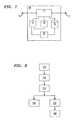
- FIG. 7shows a block diagram of a network node embodying the invention.
- FIGS. 8 , 9 and 10show flow-charts of examples of a method according to the invention.
- a linkis a channel, physical or virtual, between two nodes of a network, and may be implemented as a cable or be wireless, or as e.g. an SDH virtual channel.
- a link or portis blocked if, except for specific types of data, such as maintenance messages or in Ethernet networks, Bridge Protocol Data Units (BPDU), no data will be processed.
- BPDUBridge Protocol Data Units
- a link or portis disabled when no data at all will be processed on the respective port or link.
- a nodeis any element in a network, such as for example a general purpose computer, a router, a switch or a bridge.
- a node which is directly connected to another nodeis said to be adjacent to that other node.
- each nodewill normally have two adjacent nodes.
- the terms comprising and includingare used in this application as meaning: having but not limited to.
- the example of a network embodying the invention as shown in FIGS. 1 to 6has five network nodes 10 , 20 , 30 , 40 and 50 connected to each other in a ring topology via links 1 - 5 .
- Link 5 between network node 10 and network node 50is blocked, as indicated by the dotted lines.
- the shown example of a networkis compliant with the Bridged Ethernet standards, also known in the art as the IEEE 802.3 and IEEE 802.1 standards.
- the inventionis not limited to Bridged Ethernet networks and may also be applied in other types of networks.
- Network nodes 10 - 50each have a memory (not shown) in which addressing information is stored as an address table providing an addressing scheme.
- the network nodesmay perform a method according to the invention, for example the method illustrated by the flow-chart of FIG. 8 .
- the methodis initiated in step 101 , for example by the detection of a link failure or the reception of a network change message which indicates that the addressing scheme, in the Ethernet network known as the spanning tree, should be reconfigured.
- link 2 between network nodes 20 and 30may be physically damaged, for example because of a broken cable.
- both nodes 20 and 30detect a link failure and initiate the method of FIG. 8 in step 101 .
- step 102the respective node blocks the link for which the failure is detected to another network node;
- nodes 20 and 30block the link 2 by closing the ports (not shown) connected to link 2 on the respective node, as is indicated by the dotted line between nodes 20 and 30 .
- step 103the node sends a network change message (NCM) to a node directly connected to the node after or during the closing of the link.
- NCMnetwork change message
- node 20sends a NCM to adjacent node 10 via link 1 after closing link 2
- node 30sends a NCM to adjacent node 40 via link 3 ( FIG. 3 ).
- Steps 102 and 103may be performed in the order shown and described, or they may be performed in reverse order, or they may be performed at the same time as each other.
- the flowchart of FIG. 8divides into two branches, one comprising step 106 , and the other comprising steps 107 and 108 .
- the steps in one branchmay be performed after, or before, or preferably, for the sake of speed, at the same time as the steps of the other branch.
- nodes 20 and 30reconfigure the addressing information, in the example of FIG. 1 by at least partially erasing or flushing the, Bridged Ethernet compliant, address table.
- step 107any old queued messages are also flushed by simply deleting them or waiting for their regular transmission to finish.
- nodes 20 and 30send, in step 108 , a reconfigured message (RM) to nodes 10 and 40 , respectively, via links 1 and 3 , respectively.
- RMreconfigured message
- nodes which are not directly connected to the failed link and are not connected to a blocked linkare able to perform a method as illustrated in FIG. 9 in which, in step 101 , the method is initiated with the reception of a NCM from another node.
- node 40receives a NCM from node 30 , as shown in FIG. 3 .
- step 102in reaction to the NCM, the respective node blocks the link over which the NCM was transmitted, as indicated in FIG. 4 by the dotted lines.
- node 40blocks the port to link 3 .
- step 103which, as in FIG. 8 , may be performed before, after, or at the same time as step 102 , node 40 sends a NCM to adjacent node 50 .
- the flowchart of FIG. 9divides into three branches, the first comprising steps 104 and 105 , the second comprising step 106 , and the third comprising steps 107 and 108 .
- step 106node 40 reconfigures its addressing information by at least partially flushing its address table.
- step 107as in step 107 of FIG. 8 , the node also flushes any old queued messages, after which, in step 108 , node 40 transmits a RM to a node directly connected to the respective node for links which are open.
- node 40transmits a RM to node 50 as is shown in FIG. 6 .
- step 104node 40 checks if it has received a RM, and, if so, in step 105 node 40 de-blocks the respective link over which the RM was received (in this example the RM transmitted in step 108 of FIG. 8 ). Thus in the shown example, node 40 de-blocks the port to the blocked link 3 .
- nodes which are directly connected to a blocked linkare able to perform a method as illustrated in FIG. 10 in which, in step 101 , the method is initiated with the reception of a NCM from another node.
- node 10receives an NCM from adjacent node 20 , as shown in FIG. 3
- node 50receives an NCM from adjacent node 40 , as shown in FIG. 4 .
- step 102in reaction to the NCM, the respective node blocks the link over which the NCM was received, as indicated in FIG. 4 and FIG. 5 by the dotted lines.
- node 10blocks the port to link 1 and node 50 blocks the port to link 4 .
- the flowchart of FIG. 10divides into three branches, the first branch comprising step 106 , the second branch comprising steps 107 and 109 , and the third branch comprising step 104 and 105 .
- the steps in one branchmay be performed after, or before, or preferably, for the sake of speed, at the same time as the steps of the other branches.
- step 106nodes 10 and 50 reconfigure the addressing information, in the example of FIG. 1 by at least partially erasing or flushing the, Bridged Ethernet compliant, address table.
- step 107any old queued messages are also flushed by simply deleting them or waiting for their regular transmission to finish.
- step 109the respective node de-blocks the link over which no NCM was transmitted.
- node 10 and node 50de-block link 5 , as is shown in FIG. 6 .
- step 104the respective nodes check if they have received an RM, and, if so, in step 105 the nodes de-block the respective links over which the RM was received.
- node 10de-blocks link 1 after receiving the RM from node 20 as transmitted in step 108 of FIG. 8
- node 50de-blocks link 4 after receiving the RM as transmitted in step 108 of FIG. 9 .
- FIG. 7shows a block diagram of an example of a network node 10 embodying the invention.
- the node 10may, for example, be a general purpose computer, a router, a bridge or otherwise.
- the nodehas a data handler device 11 which is arranged to handle received data, for example by transmitting the data further, discarding the data or displaying the data.
- the data handler device 11is communicatively connected to an input port 16 and an output port 17 .
- a memory device 12Connected to data handler device 11 is a memory device 12 in which information about the data is stored, for example as an address table or routing information.
- Also connected to data handler device 11are a change detector 13 and an inhibitor device 14 .
- the change detector 13is also connected to an eraser device 15 which is connected to memory device 12 .
- the change detectordetects the necessity for changing the spanning tree, for example because detector 13 monitors the integrity of the links to which the input port 16 and the output port 17 are connected and/or detects the reception of NCMs and/or RMs. If detector 13 finds that the spanning tree has to be changed, detector 13 will send a signal to inhibitor device 14 and eraser device 15 and sends a NCM to output port 17 . Inhibitor device 14 then blocks one or more of the links connected to node 10 , while eraser device 15 will at least partially erase the addressing information in memory 12 . After having erased the addressing information, the eraser device will send a signal to detector 13 . In reaction, detector 13 will send a RM to output port 17 via data handler 11 and also will send a signal to inhibitor device 14 to stop blocking the link.
- a method, network node, or computer program product according to the inventionmay be compliant with any networking protocol, for example, the Bridged Ethernet standards, and if the invention is applied in a Bridged Ethernet network, the NCM and the RM may be implemented as bridge protocol data units (BPDU), which are already provided for in the Bridged Ethernet protocols.
- BPDUbridge protocol data units
Landscapes
- Engineering & Computer Science (AREA)
- Computer Networks & Wireless Communication (AREA)
- Signal Processing (AREA)
- Small-Scale Networks (AREA)
- Data Exchanges In Wide-Area Networks (AREA)
Abstract
Description
Claims (7)
Priority Applications (5)
| Application Number | Priority Date | Filing Date | Title |
|---|---|---|---|
| US10/452,626US8543672B2 (en) | 2003-06-02 | 2003-06-02 | Method for reconfiguring a ring network, a network node, and a computer program product |
| DE602004001489TDE602004001489T2 (en) | 2003-06-02 | 2004-05-28 | Method for reconfiguring a ring network |
| EP04253184AEP1487158B1 (en) | 2003-06-02 | 2004-05-28 | Method for reconfiguring a ring network |
| KR1020040039592AKR101094049B1 (en) | 2003-06-02 | 2004-06-01 | Method for reconfiguring loop network, network node, data communication loop network and computer readable recording medium |
| JP2004164581AJP4372618B2 (en) | 2003-06-02 | 2004-06-02 | Method for reconfiguring a ring network, network node, and computer program product |
Applications Claiming Priority (1)
| Application Number | Priority Date | Filing Date | Title |
|---|---|---|---|
| US10/452,626US8543672B2 (en) | 2003-06-02 | 2003-06-02 | Method for reconfiguring a ring network, a network node, and a computer program product |
Publications (2)
| Publication Number | Publication Date |
|---|---|
| US20050015470A1 US20050015470A1 (en) | 2005-01-20 |
| US8543672B2true US8543672B2 (en) | 2013-09-24 |
Family
ID=33299593
Family Applications (1)
| Application Number | Title | Priority Date | Filing Date |
|---|---|---|---|
| US10/452,626Active2032-04-06US8543672B2 (en) | 2003-06-02 | 2003-06-02 | Method for reconfiguring a ring network, a network node, and a computer program product |
Country Status (5)
| Country | Link |
|---|---|
| US (1) | US8543672B2 (en) |
| EP (1) | EP1487158B1 (en) |
| JP (1) | JP4372618B2 (en) |
| KR (1) | KR101094049B1 (en) |
| DE (1) | DE602004001489T2 (en) |
Families Citing this family (6)
| Publication number | Priority date | Publication date | Assignee | Title |
|---|---|---|---|---|
| US7688716B2 (en)* | 2005-05-02 | 2010-03-30 | Cisco Technology, Inc. | Method, apparatus, and system for improving ethernet ring convergence time |
| US7948922B2 (en)* | 2006-04-18 | 2011-05-24 | Cisco Technology, Inc. | Blocked redundant link-aware spanning tree protocol enhancement |
| CN101141366A (en)* | 2006-09-07 | 2008-03-12 | 华为技术有限公司 | A Method to Avoid Data Loops in Ring Ethernet |
| US20090016214A1 (en)* | 2007-07-12 | 2009-01-15 | Allied Telesis Holdings K.K. | Method and system for network recovery from multiple link failures |
| JP4977190B2 (en)* | 2009-11-12 | 2012-07-18 | 富士通テレコムネットワークス株式会社 | Communication device, interface card, and troubleshooting method |
| JP5581141B2 (en)* | 2010-07-29 | 2014-08-27 | 株式会社Pfu | Management server, communication cutoff device, information processing system, method, and program |
Citations (14)
| Publication number | Priority date | Publication date | Assignee | Title |
|---|---|---|---|---|
| US6091705A (en)* | 1996-12-20 | 2000-07-18 | Sebring Systems, Inc. | Method and apparatus for a fault tolerant, software transparent and high data integrity extension to a backplane bus or interconnect |
| US6330229B1 (en)* | 1998-11-09 | 2001-12-11 | 3Com Corporation | Spanning tree with rapid forwarding database updates |
| US6388995B1 (en)* | 1997-12-24 | 2002-05-14 | Cisco Technology, Inc. | Method and apparatus for rapidly reconfiguring computers networks executing the spanning tree algorithm |
| US20020159398A1 (en)* | 2001-04-27 | 2002-10-31 | Masataka Yamada | Spanning tree control unit in the case of trouble or increase and method thereof |
| US20020174207A1 (en)* | 2001-02-28 | 2002-11-21 | Abdella Battou | Self-healing hierarchical network management system, and methods and apparatus therefor |
| US6535490B1 (en) | 1999-03-04 | 2003-03-18 | 3Com Corporation | High availability spanning tree with rapid reconfiguration with alternate port selection |
| US6606301B1 (en)* | 1999-03-01 | 2003-08-12 | Sun Microsystems, Inc. | Method and apparatus for early random discard of packets |
| US6731596B1 (en)* | 1999-04-01 | 2004-05-04 | Advanced Micro Devices, Inc. | Network switch having system for automatically detecting change in network node connection |
| US20040160895A1 (en)* | 2003-02-14 | 2004-08-19 | At&T Corp. | Failure notification method and system in an ethernet domain |
| US20040165595A1 (en)* | 2003-02-25 | 2004-08-26 | At&T Corp. | Discovery and integrity testing method in an ethernet domain |
| US6952396B1 (en)* | 1999-09-27 | 2005-10-04 | Nortel Networks Limited | Enhanced dual counter rotating ring network control system |
| US6976088B1 (en)* | 1997-12-24 | 2005-12-13 | Cisco Technology, Inc. | Method and apparatus for rapidly reconfiguring bridged networks using a spanning tree algorithm |
| US7362709B1 (en)* | 2001-11-02 | 2008-04-22 | Arizona Board Of Regents | Agile digital communication network with rapid rerouting |
| US7496650B1 (en)* | 2003-01-09 | 2009-02-24 | Cisco Technology, Inc. | Identifying and suppressing transient routing updates |
Family Cites Families (1)
| Publication number | Priority date | Publication date | Assignee | Title |
|---|---|---|---|---|
| US4683563A (en) | 1984-10-11 | 1987-07-28 | American Telephone And Telegraph Company, At&T Bell Laboratories | Data communication network |
- 2003
- 2003-06-02USUS10/452,626patent/US8543672B2/enactiveActive
- 2004
- 2004-05-28DEDE602004001489Tpatent/DE602004001489T2/ennot_activeExpired - Lifetime
- 2004-05-28EPEP04253184Apatent/EP1487158B1/ennot_activeExpired - Lifetime
- 2004-06-01KRKR1020040039592Apatent/KR101094049B1/ennot_activeExpired - Fee Related
- 2004-06-02JPJP2004164581Apatent/JP4372618B2/ennot_activeExpired - Fee Related
Patent Citations (18)
| Publication number | Priority date | Publication date | Assignee | Title |
|---|---|---|---|---|
| US6400682B1 (en)* | 1996-12-20 | 2002-06-04 | Plx Technology, Inc. | Method and apparatus for a fault tolerant, software transparent and high data integrity extension to a backplane bus or interconnect |
| US6091705A (en)* | 1996-12-20 | 2000-07-18 | Sebring Systems, Inc. | Method and apparatus for a fault tolerant, software transparent and high data integrity extension to a backplane bus or interconnect |
| US6535491B2 (en)* | 1997-12-24 | 2003-03-18 | Cisco Technology, Inc. | Method and apparatus for rapidly reconfiguring computer networks using a spanning tree algorithm |
| US20020147800A1 (en) | 1997-12-24 | 2002-10-10 | Silvano Gai | Method and apparatus for rapidly reconfiguring computer networks using a spanning tree algorithm |
| US6976088B1 (en)* | 1997-12-24 | 2005-12-13 | Cisco Technology, Inc. | Method and apparatus for rapidly reconfiguring bridged networks using a spanning tree algorithm |
| US6388995B1 (en)* | 1997-12-24 | 2002-05-14 | Cisco Technology, Inc. | Method and apparatus for rapidly reconfiguring computers networks executing the spanning tree algorithm |
| US6330229B1 (en)* | 1998-11-09 | 2001-12-11 | 3Com Corporation | Spanning tree with rapid forwarding database updates |
| US6606301B1 (en)* | 1999-03-01 | 2003-08-12 | Sun Microsystems, Inc. | Method and apparatus for early random discard of packets |
| US6535490B1 (en) | 1999-03-04 | 2003-03-18 | 3Com Corporation | High availability spanning tree with rapid reconfiguration with alternate port selection |
| US6731596B1 (en)* | 1999-04-01 | 2004-05-04 | Advanced Micro Devices, Inc. | Network switch having system for automatically detecting change in network node connection |
| US6952396B1 (en)* | 1999-09-27 | 2005-10-04 | Nortel Networks Limited | Enhanced dual counter rotating ring network control system |
| US20020174207A1 (en)* | 2001-02-28 | 2002-11-21 | Abdella Battou | Self-healing hierarchical network management system, and methods and apparatus therefor |
| US20050259571A1 (en)* | 2001-02-28 | 2005-11-24 | Abdella Battou | Self-healing hierarchical network management system, and methods and apparatus therefor |
| US20020159398A1 (en)* | 2001-04-27 | 2002-10-31 | Masataka Yamada | Spanning tree control unit in the case of trouble or increase and method thereof |
| US7362709B1 (en)* | 2001-11-02 | 2008-04-22 | Arizona Board Of Regents | Agile digital communication network with rapid rerouting |
| US7496650B1 (en)* | 2003-01-09 | 2009-02-24 | Cisco Technology, Inc. | Identifying and suppressing transient routing updates |
| US20040160895A1 (en)* | 2003-02-14 | 2004-08-19 | At&T Corp. | Failure notification method and system in an ethernet domain |
| US20040165595A1 (en)* | 2003-02-25 | 2004-08-26 | At&T Corp. | Discovery and integrity testing method in an ethernet domain |
Non-Patent Citations (3)
| Title |
|---|
| IEEE 802.1D Standards, ISO/IEC 15802-3:1998, LAN MAC Bridges, 1998 Edition, pp. 63-64,Section 8.3.5 Notifying Topology Changes, p. 77, 'topology change notification (TCN) BPDU', p. 92.* |
| IEEE Standard 802.1D, Draft Standard for Local Area Networks MAC (Media Access Control) Bridges: Technical and Editorial Corrections, Mar. 6, 1997, pp. 3-10.85-122 and 151-158.* |
| Perlman, R., An Algorithm for Distributed Computation of Spanning Tree in an Extended LAN, ACM ISSN 0146-4833, 1985, pp. 44-53.* |
Also Published As
| Publication number | Publication date |
|---|---|
| EP1487158A1 (en) | 2004-12-15 |
| DE602004001489D1 (en) | 2006-08-24 |
| DE602004001489T2 (en) | 2007-07-05 |
| EP1487158B1 (en) | 2006-07-12 |
| US20050015470A1 (en) | 2005-01-20 |
| KR20040103787A (en) | 2004-12-09 |
| JP2004364302A (en) | 2004-12-24 |
| JP4372618B2 (en) | 2009-11-25 |
| KR101094049B1 (en) | 2011-12-19 |
Similar Documents
| Publication | Publication Date | Title |
|---|---|---|
| US7969915B2 (en) | Technical enhancements to STP (IEEE 802.1D) implementation | |
| US8937869B2 (en) | Communication device, communication system, and communication fault detection method | |
| US7339888B2 (en) | Bridge and route change method of network using the same | |
| US8699380B2 (en) | Port table flushing in ethernet networks | |
| EP2150007B1 (en) | Layer two mac re-routing | |
| US8270412B2 (en) | Network relay device and ring network | |
| US8031592B2 (en) | Network having redundancy properties, Ethernet switch for such a network and method for configuring such a network | |
| US8687523B2 (en) | System and method for integrating ring-protocol-compatible devices into network configurations that also include non-ring-protocol compatible devices | |
| US20200044964A1 (en) | Defect detection in ip/mpls network tunnels | |
| JP2008167315A (en) | Redundant line connection method and wide area network node device | |
| US8543672B2 (en) | Method for reconfiguring a ring network, a network node, and a computer program product | |
| JP4229810B2 (en) | Communication test equipment | |
| US20030161275A1 (en) | Spanning tree method | |
| CN104780138B (en) | The transmitting method and device of STP/RSTP messages in privately owned redundancy protocol network | |
| WO2004066562A1 (en) | Data transmission apparatus | |
| CN112737889B (en) | Flow processing method, flow monitoring method, device, system and storage medium | |
| AU2012390581B2 (en) | Method for running a computer network | |
| JP2003324463A (en) | Communication path switching device | |
| CN101939956A (en) | Method for communicating data between terminal devices from a plurality of Ethernet networks of a redundancy system | |
| CN113875196B (en) | Communication device | |
| KR101992713B1 (en) | Communication interface apparatus | |
| JPH05268221A (en) | Frame relay system of LAN connection device |
Legal Events
| Date | Code | Title | Description |
|---|---|---|---|
| AS | Assignment | Owner name:LUCENT TECHNOLOGIES INC., NEW JERSEY Free format text:ASSIGNMENT OF ASSIGNORS INTEREST;ASSIGNORS:HEER, ARIE JOHANNES;DE MAN, RONALD;REEL/FRAME:014150/0865;SIGNING DATES FROM 20030305 TO 20030428 Owner name:LUCENT TECHNOLOGIES INC., NEW JERSEY Free format text:ASSIGNMENT OF ASSIGNORS INTEREST;ASSIGNORS:HEER, ARIE JOHANNES;DE MAN, RONALD;SIGNING DATES FROM 20030305 TO 20030428;REEL/FRAME:014150/0865 | |
| FEPP | Fee payment procedure | Free format text:PAYOR NUMBER ASSIGNED (ORIGINAL EVENT CODE: ASPN); ENTITY STATUS OF PATENT OWNER: LARGE ENTITY | |
| AS | Assignment | Owner name:CREDIT SUISSE AG, NEW YORK Free format text:SECURITY AGREEMENT;ASSIGNOR:LUCENT, ALCATEL;REEL/FRAME:029821/0001 Effective date:20130130 Owner name:CREDIT SUISSE AG, NEW YORK Free format text:SECURITY AGREEMENT;ASSIGNOR:ALCATEL LUCENT;REEL/FRAME:029821/0001 Effective date:20130130 | |
| AS | Assignment | Owner name:ALCATEL-LUCENT USA INC., NEW JERSEY Free format text:MERGER;ASSIGNOR:LUCENT TECHNOLOGIES INC.;REEL/FRAME:030804/0019 Effective date:20081101 | |
| AS | Assignment | Owner name:ALCATEL LUCENT, FRANCE Free format text:ASSIGNMENT OF ASSIGNORS INTEREST;ASSIGNOR:ALCATEL-LUCENT USA INC.;REEL/FRAME:030839/0206 Effective date:20130717 | |
| STCF | Information on status: patent grant | Free format text:PATENTED CASE | |
| AS | Assignment | Owner name:ALCATEL LUCENT, FRANCE Free format text:RELEASE BY SECURED PARTY;ASSIGNOR:CREDIT SUISSE AG;REEL/FRAME:033868/0555 Effective date:20140819 | |
| FPAY | Fee payment | Year of fee payment:4 | |
| AS | Assignment | Owner name:PROVENANCE ASSET GROUP LLC, CONNECTICUT Free format text:ASSIGNMENT OF ASSIGNORS INTEREST;ASSIGNORS:NOKIA TECHNOLOGIES OY;NOKIA SOLUTIONS AND NETWORKS BV;ALCATEL LUCENT SAS;REEL/FRAME:043877/0001 Effective date:20170912 Owner name:NOKIA USA INC., CALIFORNIA Free format text:SECURITY INTEREST;ASSIGNORS:PROVENANCE ASSET GROUP HOLDINGS, LLC;PROVENANCE ASSET GROUP LLC;REEL/FRAME:043879/0001 Effective date:20170913 Owner name:CORTLAND CAPITAL MARKET SERVICES, LLC, ILLINOIS Free format text:SECURITY INTEREST;ASSIGNORS:PROVENANCE ASSET GROUP HOLDINGS, LLC;PROVENANCE ASSET GROUP, LLC;REEL/FRAME:043967/0001 Effective date:20170913 | |
| AS | Assignment | Owner name:NOKIA US HOLDINGS INC., NEW JERSEY Free format text:ASSIGNMENT AND ASSUMPTION AGREEMENT;ASSIGNOR:NOKIA USA INC.;REEL/FRAME:048370/0682 Effective date:20181220 | |
| MAFP | Maintenance fee payment | Free format text:PAYMENT OF MAINTENANCE FEE, 8TH YEAR, LARGE ENTITY (ORIGINAL EVENT CODE: M1552); ENTITY STATUS OF PATENT OWNER: LARGE ENTITY Year of fee payment:8 | |
| AS | Assignment | Owner name:PROVENANCE ASSET GROUP LLC, CONNECTICUT Free format text:RELEASE BY SECURED PARTY;ASSIGNOR:CORTLAND CAPITAL MARKETS SERVICES LLC;REEL/FRAME:058983/0104 Effective date:20211101 Owner name:PROVENANCE ASSET GROUP HOLDINGS LLC, CONNECTICUT Free format text:RELEASE BY SECURED PARTY;ASSIGNOR:CORTLAND CAPITAL MARKETS SERVICES LLC;REEL/FRAME:058983/0104 Effective date:20211101 Owner name:PROVENANCE ASSET GROUP LLC, CONNECTICUT Free format text:RELEASE BY SECURED PARTY;ASSIGNOR:NOKIA US HOLDINGS INC.;REEL/FRAME:058363/0723 Effective date:20211129 Owner name:PROVENANCE ASSET GROUP HOLDINGS LLC, CONNECTICUT Free format text:RELEASE BY SECURED PARTY;ASSIGNOR:NOKIA US HOLDINGS INC.;REEL/FRAME:058363/0723 Effective date:20211129 | |
| AS | Assignment | Owner name:RPX CORPORATION, CALIFORNIA Free format text:ASSIGNMENT OF ASSIGNORS INTEREST;ASSIGNOR:PROVENANCE ASSET GROUP LLC;REEL/FRAME:059352/0001 Effective date:20211129 | |
| AS | Assignment | Owner name:BARINGS FINANCE LLC, AS COLLATERAL AGENT, NORTH CAROLINA Free format text:PATENT SECURITY AGREEMENT;ASSIGNOR:RPX CORPORATION;REEL/FRAME:063429/0001 Effective date:20220107 | |
| AS | Assignment | Owner name:RPX CORPORATION, CALIFORNIA Free format text:RELEASE OF LIEN ON PATENTS;ASSIGNOR:BARINGS FINANCE LLC;REEL/FRAME:068328/0278 Effective date:20240802 | |
| AS | Assignment | Owner name:BARINGS FINANCE LLC, AS COLLATERAL AGENT, NORTH CAROLINA Free format text:PATENT SECURITY AGREEMENT;ASSIGNORS:RPX CORPORATION;RPX CLEARINGHOUSE LLC;REEL/FRAME:068328/0674 Effective date:20240802 | |
| FEPP | Fee payment procedure | Free format text:MAINTENANCE FEE REMINDER MAILED (ORIGINAL EVENT CODE: REM.); ENTITY STATUS OF PATENT OWNER: LARGE ENTITY |