US8543365B1 - Computer-readable medium, a method and an apparatus for designing and simulating electrodynamic machines implementing conical and cylindrical magnets - Google Patents
Computer-readable medium, a method and an apparatus for designing and simulating electrodynamic machines implementing conical and cylindrical magnetsDownload PDFInfo
- Publication number
- US8543365B1 US8543365B1US11/707,285US70728507AUS8543365B1US 8543365 B1US8543365 B1US 8543365B1US 70728507 AUS70728507 AUS 70728507AUS 8543365 B1US8543365 B1US 8543365B1
- Authority
- US
- United States
- Prior art keywords
- field pole
- coil
- executable instructions
- active field
- motor
- Prior art date
- Legal status (The legal status is an assumption and is not a legal conclusion. Google has not performed a legal analysis and makes no representation as to the accuracy of the status listed.)
- Expired - Fee Related, expires
Links
- 238000000034methodMethods0.000titleclaimsabstractdescription32
- 230000005520electrodynamicsEffects0.000titleclaimsabstractdescription28
- 230000004907fluxEffects0.000claimsdescription83
- 239000000463materialSubstances0.000claimsdescription41
- 238000004513sizingMethods0.000claims9
- 238000013461designMethods0.000abstractdescription56
- 239000000470constituentSubstances0.000abstractdescription3
- 230000005291magnetic effectEffects0.000description50
- 230000003993interactionEffects0.000description27
- 238000004804windingMethods0.000description17
- 238000004519manufacturing processMethods0.000description16
- RYGMFSIKBFXOCR-UHFFFAOYSA-NCopperChemical compound[Cu]RYGMFSIKBFXOCR-UHFFFAOYSA-N0.000description8
- 229910052802copperInorganic materials0.000description8
- 239000010949copperSubstances0.000description8
- 230000003068static effectEffects0.000description8
- XEEYBQQBJWHFJM-UHFFFAOYSA-NironSubstances[Fe]XEEYBQQBJWHFJM-UHFFFAOYSA-N0.000description6
- 238000004088simulationMethods0.000description6
- 238000004364calculation methodMethods0.000description5
- 230000008859changeEffects0.000description5
- 239000002131composite materialSubstances0.000description5
- 238000010586diagramMethods0.000description5
- 230000009977dual effectEffects0.000description5
- 230000004048modificationEffects0.000description5
- 238000012986modificationMethods0.000description5
- 238000012856packingMethods0.000description5
- 230000035699permeabilityEffects0.000description5
- 230000010287polarizationEffects0.000description5
- 230000006399behaviorEffects0.000description4
- 238000012938design processMethods0.000description4
- 229910000640Fe alloyInorganic materials0.000description3
- 238000004458analytical methodMethods0.000description3
- 230000008901benefitEffects0.000description3
- 239000004020conductorSubstances0.000description3
- 238000011217control strategyMethods0.000description3
- 239000003302ferromagnetic materialSubstances0.000description3
- 230000006870functionEffects0.000description3
- 229910052742ironInorganic materials0.000description3
- 230000007704transitionEffects0.000description3
- 229910000831SteelInorganic materials0.000description2
- 230000001133accelerationEffects0.000description2
- 230000004323axial lengthEffects0.000description2
- 230000015572biosynthetic processEffects0.000description2
- 238000011960computer-aided designMethods0.000description2
- 230000001419dependent effectEffects0.000description2
- 238000011161developmentMethods0.000description2
- 230000018109developmental processEffects0.000description2
- 239000011888foilSubstances0.000description2
- 230000006872improvementEffects0.000description2
- 238000012804iterative processMethods0.000description2
- 239000000696magnetic materialSubstances0.000description2
- 238000004806packaging method and processMethods0.000description2
- 239000000843powderSubstances0.000description2
- 230000004044responseEffects0.000description2
- 210000000329smooth muscle myocyteAnatomy0.000description2
- 239000010959steelSubstances0.000description2
- 229910000851Alloy steelInorganic materials0.000description1
- 229910000990Ni alloyInorganic materials0.000description1
- 229920007962Styrene Methyl MethacrylatePolymers0.000description1
- PXAWCNYZAWMWIC-UHFFFAOYSA-N[Fe].[Nd]Chemical compound[Fe].[Nd]PXAWCNYZAWMWIC-UHFFFAOYSA-N0.000description1
- 230000001154acute effectEffects0.000description1
- 229910045601alloyInorganic materials0.000description1
- 239000000956alloySubstances0.000description1
- 229910052782aluminiumInorganic materials0.000description1
- XAGFODPZIPBFFR-UHFFFAOYSA-NaluminiumChemical compound[Al]XAGFODPZIPBFFR-UHFFFAOYSA-N0.000description1
- 238000013459approachMethods0.000description1
- 239000000919ceramicSubstances0.000description1
- 238000006243chemical reactionMethods0.000description1
- NVIVJPRCKQTWLY-UHFFFAOYSA-Ncobalt nickelChemical compound[Co][Ni][Co]NVIVJPRCKQTWLY-UHFFFAOYSA-N0.000description1
- 238000005056compactionMethods0.000description1
- 150000001875compoundsChemical class0.000description1
- 238000004590computer programMethods0.000description1
- 238000005094computer simulationMethods0.000description1
- 238000001816coolingMethods0.000description1
- 238000013479data entryMethods0.000description1
- 238000009826distributionMethods0.000description1
- 230000000694effectsEffects0.000description1
- 230000005672electromagnetic fieldEffects0.000description1
- 238000005516engineering processMethods0.000description1
- 230000007613environmental effectEffects0.000description1
- 238000011156evaluationMethods0.000description1
- 230000002349favourable effectEffects0.000description1
- 239000000945fillerSubstances0.000description1
- 230000017525heat dissipationEffects0.000description1
- 238000009413insulationMethods0.000description1
- UGKDIUIOSMUOAW-UHFFFAOYSA-Niron nickelChemical compound[Fe].[Ni]UGKDIUIOSMUOAW-UHFFFAOYSA-N0.000description1
- XWHPIFXRKKHEKR-UHFFFAOYSA-Niron siliconChemical compound[Si].[Fe]XWHPIFXRKKHEKR-UHFFFAOYSA-N0.000description1
- 238000003475laminationMethods0.000description1
- 239000006249magnetic particleSubstances0.000description1
- 230000005415magnetizationEffects0.000description1
- 230000007246mechanismEffects0.000description1
- 229910052751metalInorganic materials0.000description1
- 239000002184metalSubstances0.000description1
- 239000007769metal materialSubstances0.000description1
- 239000005300metallic glassSubstances0.000description1
- 150000002739metalsChemical class0.000description1
- 230000003278mimic effectEffects0.000description1
- 210000001611motor endplateAnatomy0.000description1
- 230000002093peripheral effectEffects0.000description1
- 238000004382pottingMethods0.000description1
- 230000008569processEffects0.000description1
- 238000004549pulsed laser depositionMethods0.000description1
- 229910052761rare earth metalInorganic materials0.000description1
- 150000002910rare earth metalsChemical class0.000description1
- 238000012546transferMethods0.000description1
Images


Classifications
- H—ELECTRICITY
- H02—GENERATION; CONVERSION OR DISTRIBUTION OF ELECTRIC POWER
- H02K—DYNAMO-ELECTRIC MACHINES
- H02K1/00—Details of the magnetic circuit
- H02K1/06—Details of the magnetic circuit characterised by the shape, form or construction
- H02K1/12—Stationary parts of the magnetic circuit
- H02K1/14—Stator cores with salient poles
- H—ELECTRICITY
- H02—GENERATION; CONVERSION OR DISTRIBUTION OF ELECTRIC POWER
- H02K—DYNAMO-ELECTRIC MACHINES
- H02K16/00—Machines with more than one rotor or stator
- H—ELECTRICITY
- H02—GENERATION; CONVERSION OR DISTRIBUTION OF ELECTRIC POWER
- H02K—DYNAMO-ELECTRIC MACHINES
- H02K21/00—Synchronous motors having permanent magnets; Synchronous generators having permanent magnets
- H02K21/12—Synchronous motors having permanent magnets; Synchronous generators having permanent magnets with stationary armatures and rotating magnets
- H—ELECTRICITY
- H02—GENERATION; CONVERSION OR DISTRIBUTION OF ELECTRIC POWER
- H02K—DYNAMO-ELECTRIC MACHINES
- H02K2201/00—Specific aspects not provided for in the other groups of this subclass relating to the magnetic circuits
- H02K2201/03—Machines characterised by aspects of the air-gap between rotor and stator
- H—ELECTRICITY
- H02—GENERATION; CONVERSION OR DISTRIBUTION OF ELECTRIC POWER
- H02K—DYNAMO-ELECTRIC MACHINES
- H02K2201/00—Specific aspects not provided for in the other groups of this subclass relating to the magnetic circuits
- H02K2201/06—Magnetic cores, or permanent magnets characterised by their skew
- H—ELECTRICITY
- H02—GENERATION; CONVERSION OR DISTRIBUTION OF ELECTRIC POWER
- H02K—DYNAMO-ELECTRIC MACHINES
- H02K2201/00—Specific aspects not provided for in the other groups of this subclass relating to the magnetic circuits
- H02K2201/12—Transversal flux machines
- H—ELECTRICITY
- H02—GENERATION; CONVERSION OR DISTRIBUTION OF ELECTRIC POWER
- H02K—DYNAMO-ELECTRIC MACHINES
- H02K2213/00—Specific aspects, not otherwise provided for and not covered by codes H02K2201/00 - H02K2211/00
- H02K2213/03—Machines characterised by numerical values, ranges, mathematical expressions or similar information
Definitions
- Embodiments of the inventionrelate generally to electric motors, alternators, generators and the like, and more particularly, to an apparatus, a method, and a computer-readable medium for modeling a rotor-stator structure to design and/or simulate electrodynamic machines.
- a method, apparatus, system and computer readable medium for designing and/or simulating electrodynamic machineryare disclosed to, among other things, optimize one or more performance characteristics by manipulating structural and/or functional characteristics of the constituent components of an electrodynamic machine.
- a motor designercan create a motor design using, for example, computer-modeled rotor-stator structures implementing, for example, conically-shaped magnets and/or cylindrically-shaped magnets, with accompanying field pole members.
- a motor designercan start by defining the desired structural and/or operational characteristics for the motor, including the magnet shape or the shape of a pole face for the field pole members.
- a set of design motor rulescan be developed and applied to the structural and/or operational characteristics to make specific choices that determine specific aspects of the motor design.
- design tradeoffsare made among a variety of structural and/or functional characteristics. For example, improvement of one performance characteristic, such as output torque, might affect another desired characteristic performance characteristic, such as the size or weight of the motor.
- the motor design processcan be an iterative process where a set of choices is made and then compared to the desired outcome. Then, those choices can be modified to see if an overall better design outcome can be achieved.
- a methodidentifies a subset of structural and/or operational characteristics for at least designing a motor.
- the methodcan also define the basic motor constraints, such as the overall motor outside diameter, a stator assembly diameter and/or cross-sectional area for an arrangement of field pole members (e.g., active field pole members), desired output torque, operating speed, acceleration requirements, acceptable current density, maximum speed, load inertia, available input power, motor driver, control strategy, and the like.
- the methodcan modify the subset of structural and/or operational characteristics to design a motor that can achieve a subset of performance characteristics.
- these performance characteristicsinclude, but are not limited to: maximum torque per unit volume, maximum torque per unit weight, efficiency, high rotational speed, detent minimization, ripple torque minimization, manufacturing cost, and the like.
- a motoris designed using a prioritized list of performance characteristics.
- a computer readable mediumincludes one or more instructions for implementing the methods of the various embodiments of the invention. As such, a group of program instructions can be implemented to design a motor that achieves a particular performance characteristic in view of certain motor design constraints.
- FIG. 1is a generalized flow for designing and simulating an electrodynamic machine in accordance with a specific embodiment of the present invention
- FIG. 2illustrates the modification of a rotor-stator size—as a structural and/or operational characteristic—for adjusting a performance characteristic of a motor, according to an embodiment of the invention
- FIG. 3is a block diagram illustrating a computer apparatus for at least designing a motor using a computer-based model, according to a specific embodiment of the present invention
- FIG. 4depicts an example of a lengthwise cross-section view of a motor topology showing structural/operational characteristics of the components influencing the design of a motor, according to a specific embodiment of the invention
- FIG. 5depicts a cross-section end view of the motor topology shown in FIG. 4 to illustrate additional structural/operational characteristics of motor components that can influence motor design, according to a specific embodiment of the invention
- FIGS. 6A to 6Fdepict examples of various performance characteristic modules that invoke specific modules to implement structural/operational characteristics for achieving one or more performance characteristics for a motor, according to various specific embodiments of the invention
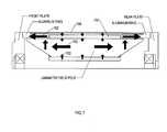
- FIG. 7depicts thermal paths for a motor topology in which a motor and its components are designed in view of thermal performance as a performance characteristic for a motor, according to one embodiment of the invention
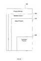
- FIG. 8is a block diagram illustrating a program memory for a computer apparatus configured to at least simulate a motor, according to a specific embodiment of the invention.
- FIG. 9is a flow that can be implemented by at least a simulation program in accordance with a specific embodiment of the invention.
- FIG. 10is a flow that can be implemented by at least a design and/or simulation program in accordance with a specific embodiment of the invention.
- air gaprefers to a space, or a gap, between a magnet surface and a confronting pole face. Such a space can be physically described as a volume bounded at least by the areas of the magnet surface and the pole face.
- An air gapfunctions to enable relative motion between a rotor and a stator, for example, and to define a flux interaction region.
- an air gapis typically filled with air, it need not be so limiting.
- back-ironcommonly describes a physical structure (as well as the materials giving rise to that physical structure) that is often used to complete an otherwise open magnetic circuit.
- back-iron structuresare generally used only to transfer magnetic flux from one magnetic circuit element to another, such as either from one magnetically permeable field pole member to another, or from a magnet pole of a first magnet to a magnet pole of a second magnet, or both, without an intervening ampere-turn generating element, such as coil, between the field pole members or the magnet poles.
- back-iron structuresare not generally formed to accept an associated ampere-turn generating element, such as one or more coils).
- the term “coil”refers to an assemblage of successive convolutions of a conductor arranged to inductively couple to a magnetically permeable material to produce magnetic flux.
- the term “coil”can be described as a “winding” or a “coil winding.”
- the term “coil”also includes foil coils (i.e., planar-shaped conductors that are relatively flat).
- coil regionrefers generally to a portion of a field pole member around which a coil is wound.
- the term “copper loss,” at in at least one embodiment,generally refers to the power losses in coil windings, regardless of the material of which the winding is constituted. These losses can be expressed in terms of the product of the resistance of windings, (e.g., in ohms), and a current, “I”, squared, (e.g., in amperes squared, or I ⁇ 2). Alternatively, this term can be referred to as “I ⁇ 2 R loss.”
- the term “core”refers to a portion of a field pole member where a coil is normally disposed between pole shoes and is generally composed of a magnetically permeable material for providing a part of a magnetic flux path. In some embodiments, the formation of the “core” also forms the field pole member with or without pole faces. In other embodiments, the core is formed as a base structure onto which end caps or the like can be formed.
- a field pole memberrefers generally to an element composed of a magnetically permeable material and being configured to provide a structure around which a coil can be wound (i.e., the element is configured to receive a coil for purposes of generating magnetic flux).
- a field pole memberincludes a core (i.e., core region) and at least two pole shoes, each of which is generally located near a respective end of the core. But in other embodiments, a field pole member includes a core and only one pole shoe.
- a field pole membercan be described generally as a “stator-core.”
- a field pole membergenerally has an elongated shape such that the length of the field pole member (e.g., the distance between the ends of the field pole member) is generally greater than its width (e.g., the width of the core).
- active field pole memberrefers to an assemblage of a core, one or more coils, and at least one pole shoe.
- an active field pole membercan be described as a field pole member assembled with one or more coils for selectably generating ampere-turn flux.
- active field pole membercan be described generally as a “stator-core member.”
- the term “ferromagnetic material”refers to a material that generally exhibits hysteresis phenomena and whose permeability is dependent on the magnetizing force. Also, the term “ferromagnetic material” can also refer to a magnetically permeable material whose relative permeability is greater than unity and depends upon the magnetizing force.
- field interaction regionrefers to a region where the magnetic flux developed from two or more sources interact vectorially in a manner that can produce mechanical force and/or torque relative to those sources.
- flux interaction regioncan be used interchangeably with the term “field interaction region.” Examples of such sources include field pole members, active field pole members, and/or magnets, or portions thereof.
- a field interaction regionis often referred to in rotating machinery parlance as an “air gap,” a field interaction region is a broader term that describes a region in which magnetic flux from two or more sources interact vectorially to produce mechanical force and/or torque relative to those sources, and therefore is not limited to the definition of an air gap (i.e., not confined to a volume defined by the areas of the magnet surface and the pole face and planes extending from the peripheries between the two areas).
- a field interaction region(or at least a portion thereof) can be located internal to a magnet.
- generatorgenerally refers to an electrodynamic machine that is configured to convert mechanical energy into electrical energy regardless of, for example, its output voltage waveform.
- alternatorcan be defined similarly, the term generator includes alternators in its definition.
- magnetrefers to a body that produces a magnetic field externally unto itself.
- magnetincludes permanent magnets, electromagnets, and the like.
- motorgenerally refers to an electrodynamic machine that is configured to convert electrical energy into mechanical energy.
- magnetically permeableis a descriptive term that generally refers to those materials having a magnetically definable relationship between flux density (“B”) and applied magnetic field (“H”). Further, “magnetically permeable” is intended to be a broad term that includes, without limitation, ferromagnetic materials, including laminate steels and cold-rolled grain oriented (“CRGO”) steels, powder metals, soft magnetic composites (“SMCs”), and the like.
- CRGOcold-rolled grain oriented
- SMCssoft magnetic composites
- pole facerefers to a surface of a pole shoe that faces at least a portion of the flux interaction region (as well as the air gap), thereby forming one boundary of the flux interaction region (as well as the air gap).
- pole facecan be described generally as either a “stator surface” or a “flux interaction surface” (or a portion thereof), or both.
- pole shoerefers to that portion of a field pole member that facilitates positioning a pole face so that it confronts a rotor (or a portion thereof), thereby serving to shape the air gap and control its reluctance.
- a pole shoe of a field pole memberis generally located near an end of the core starting at or near a coil region and terminating at the pole face.
- the term “pole shoe”can be described generally as a “stator region.”
- soft magnetic compositesrefers to those materials that are comprised, in part, of insulated magnetic particles, such as insulation-coated magnetically permeable powder metal materials that can be molded to form an element of the rotor-stator structure of the present invention.
- transition regionrefers to an optional portion of a pole shoe that facilitates offsetting or diverting a segment of a flux path (e.g., within a core region) to another segment of the flux path (e.g., within a pole shoe).
- One or more pole shoescan implement transition regions to improve motor volumetric utilization (e.g., by placing coils in a compact configuration nearer to an axis of rotation).
- the transition regioncan keep the reluctance of the field pole member relatively low while facilitating compaction of the elements constituting an electrodynamic machine.
- Such elementsinclude shafts, field pole members, magnets and the like.
- FIG. 1is a generalized flow for designing and simulating an electrodynamic machine in accordance with a specific embodiment of the present invention.
- Flow 100provides for the design of an electrodynamic machine at 102 as well as the optional simulation of the electrodynamic machine at 152 . Note that in some embodiments, the design at 102 and the simulation at 152 can occur substantially in parallel and/or reiteratively.
- Flow 100selects one or more magnets at 110 from a selection of magnets that includes conical magnets. The one or more magnets can be for a rotor of the electrodynamic machine. In some cases, the selection can also include cylindrical magnets. Conical-shaped and cylindrical-shaped magnets that are suitable for practicing at least one embodiment are described in U.S. Pat. No.
- a choice between cylindrical or conical magnetsinfluences the structure and/or operational characteristics of components that, in turn, can affect the performance characteristics of a motor design.
- conical magnetscan provide an optimal overall packing density, as well as a relatively superior flux path with minimal flux leakage.
- the use of cylindrical magnetscan ease motor production. Note, too, that flow 100 —in some embodiments—can select either a single magnet or two magnets (i.e., the “dual magnet design”).
- the dual magnet designcan produce an optimal flux path by excluding the use of “back iron” structure to establish a return path.
- the dual magnet designcan also reduce magnetic flux leakage in some cases.
- flow 100can be preceded by determining a set of constraints that will restrict certain aspects of the motor design.
- FIG. 1represents a subset of an exemplary design method to obtain, for example, structural and/or operational characteristics that relate to at least one embodiment of motor design
- flow 100can continue to 120 .
- the flowdetermines an angle (“alpha” in FIG. 3 ) at which a surface of a conical magnet is located with respect to an axis of rotation, as well as another angle (“theta” in FIG. 3 ) at which a pole face surface of a field pole member is located with respect to the axis.
- these anglescan be the same or can be different, and they can influence the magnet length (“L” in FIG. 3 ) along an axis as well as the surface area of a pole face.
- the pole face area multiplied by the air gap flux density produced by the magnetcan determine the level of flux in the field pole core midsection, thereby influencing motor torque production.
- Flow 100determines a width (“W” in FIG. 3 ) of an air gap at 130 , such as air gap 303 of FIG. 3 .
- the width of an air gapis synonymous with its thickness.
- the torque production for motors of some embodimentsneed not be strongly dependent on the width of the air gap as the use of both two conical magnets and highly permeable field poles create a favorable magnetic flux path.
- the gap widthcan affect the total flux leakage around the magnets. In one instance, a narrow air gap can reduce stray flux leakage. So, if leakage is not considered to be a relevant constraint for a motor design, flow 100 can vary the width of the air gap in favor of optimizing other structural and/or operational characteristics.
- motor efficiencycan be set by changing coil and motor length (“L” in FIG. 2 and “LL” in FIG. 3 ) while maintaining, for example, a substantially constant coil diameter (and/or cross-sectional area of an arrangement of active field pole members), unlike predominant conventional motors and their designs.
- the coil lengthcan be changed while maintaining other features (or structural and/or operational characteristics) of the motor. Note that changing coil length alters the I ⁇ 2R copper loss in the motor. And since copper loss is a controlling factor in the design of motors, this means that the motor efficiency can be directly adjusted. That is, the length of the coil can be extended without materially affecting a motor's overall magnetic characteristics. In whole or in part, this is because of the flux path(s) created by a dual conical magnet configuration as well as the high permeability of the field pole members.
- FIG. 2illustrates the modification of a rotor-stator size—as a structural and/or operational characteristic—for adjusting a performance characteristic of a motor, according to an embodiment of the invention.
- Diagram 200shows field pole member 202 and field pole member 204 .
- field pole member 202is used for a first motor, and has a coil length of “L” and a coil thickness of “T.”
- This coil 212will have “N” turns of a specific wire size with resistance of “R,” and it will operate at “I” amperes of current to produce “TQ” torque.
- Next consider the use of field pole member 204whereby the length, “L,” of coil 212 is doubled.
- Coil 214would then have a coil length of “2L.”
- the coil thickness, “T”can remain substantially constant during the resizing of the coil length and/or the field pole member length. By doubling the coil length to 2L, this doubles the number of turns of a specific wire size to “2N.”
- coil 214has a resistance of “2R” and will operate with current at about one-half “I” or “0.5I” to produce “TQ” torque.
- the power, “P 1 ,” in the first casecan be “I squared times R” and the power in the second case, “P 2 ,” can be “(0.5I) squared times 2R.” As such, power P 2 is equivalent to one-half power P 1 .
- motor efficiencycan scale with the motor's length, but be independent of any or all of the following: a cross-sectional area of, for example, an arrangement of field pole members and/or a diameter of stator assembly, the coil diameter, the coil thickness, and/or wire size.
- a performance characteristicsuch as efficiency, a motor constant (“Km”), and torque, can be adjusted by, for example, changing a coil length while maintaining a cross-sectional area of a stator assembly of a rotor-stator structure (e.g., an assemblage of field poles and coils) in a plane that is perpendicular (or substantially perpendicular) to an axis of rotation. As shown in FIG.
- perimeter 505encloses a representative cross-sectional area that can remain relatively constant, for example, during adjustment in lengths of a coil (e.g., in an axial direction) and/or a field pole member (e.g., an active field pole member) for changing one or more performance characteristics of a rotor-stator structure.
- coil lengthrefers, at least in one embodiment, to the end-to-end dimension of a coil measured in substantially an axially direction. As such, the coil length can, in some cases, be determined with respect to the length of a field pole around which the coil is wound. In one embodiment, the coil length of cantered windings can be determined substantially parallel to the length of a field pole and the axis of rotation.
- the power required to produce approximately the same torquecan be cut in half.
- the flux path design of the design motorneed not be affected by an increase in either a coil length or a field pole length, or both.
- no changesneed be necessary to the magnets or pole shoes of the field poles. Rather, it is sufficient to change the length of a coil, and optionally the length of the field pole member, to alter, for example, a performance characteristic. So to improve efficiency, the design modifications (as well as manufacturing costs) can generally be associated with changes in the length of the coil, as well as optional changes in the lengths of the field pole members.
- a change in a physical attribute or a size of a rotor-stator structure component, such as lengthcan change motor efficiency. For example, if the length of the coil is changed to 3L, the power drops to 0.3333I2 ⁇ R. With long extended motors, relatively high performance with respect to torque and speed can be obtained with reduced currents. As should be readily apparent, if a designer desires to attain a higher output torque, the designer can set the current to remain constant to maintain the same power dissipation, and then increase the coil length, rather than reducing the current for the purpose of reducing the power dissipation and increasing efficiency. Note that torque production is limited to magnetic saturation of materials. As such, this approach of changing the length of the coil to produce more torque, for example, will generally continue to work until magnetic saturation of the field poles is reached.
- FIG. 3is a block diagram illustrating a computer apparatus for at least designing a motor, according to a specific embodiment of the present invention.
- Computer apparatus 300includes a display for presenting a graphical user interface 302 , a processor (“CPU”) 305 , user inputs/outputs (“I/O”) 306 , program memory 310 and additional memory for implementing a database 370 , all of which are communicatively coupled by a bus 301 .
- User inputs/outputs (“I/O”) 306can accept data describing motor components using a command line interface (not shown) or graphical user interface 302 .
- Program memory 310includes executable instructions for implementing an operating system 320 and a design program 330 , which includes repository 340 of performance characteristics modules 342 in this example.
- design programrefers generally, at least in one embodiment, to executable instructions for modeling, analyzing and/or predicting responses and interactions of a motor design and its components.
- design program 330can be used in computer-aided design (“CAD”) applications, computer-aided manufacturing (“CAM”) applications, and computer-aided engineering (“CAE”) applications to generate a model of a rotor-stator structure and/or an electrodynamic machine, according to various embodiments of the invention.
- CADcomputer-aided design
- CAMcomputer-aided manufacturing
- CAEcomputer-aided engineering
- design program 330can be used to design and simulate mechanical, electrical and/or magnetic aspects for the purposes of simulation, drafting, engineering, performing analysis and manufacturing.
- performance characteristicgenerally refers, at least in one embodiment, to a characteristic for a motor that, for example, is quantifiable and can be used to compare against the performance of other motor designs.
- Each of performance characteristics modules 342is composed of executable instructions for designing a motor to achieve a certain performance characteristic.
- Examples of performance characteristic modules 342include instructions for maximizing torque per unit diameter (e.g. diameter of a stator assembly) or cross-sectional area (e.g., of an arrangement of field pole members), maximizing motor efficiency, improving a motor constant, Km, maximizing torque per unit weight, maximizing high speed operation, minimizing detent and torque ripple, minimizing manufacturing cost, optimizing current density, determining a maximum speed of operation, and the like.
- a specific performance characteristic module 342When a specific performance characteristic module 342 is executed, it can reference one or more structural/operational characteristics modules 362 and/or one or more constraint modules 352 to determine the particular performance characteristic.
- CPU 305executes instructions constituting design program 330 to apply constrains associated with constraints modules 352 to the structural/operational characteristics associated with structural/operational characteristic modules 362 to make specific choices that determine the specific performance characteristics of the motor design.
- design tradeoffscan be made among a variety of structural and/or functional characteristics. For example, improvement of one performance characteristic, such as output torque, might affect another desired characteristic performance characteristic, such as the size or weight of the motor. Because of these tradeoffs, the motor design process can be an iterative process where a set of choices is made and then compared to the desired outcome. Then, design program 330 can modify those choices to see if an overall improved design outcome can be achieved in view of one or more performance characteristics sought.
- performance characteristic modules 342are prioritized such that design program 330 operates to modify various structural/operational characteristics to attain those performance characteristics having a higher priority.
- one or more constraintscan be assigned as a higher priority.
- design program 330operates to optimize a subset of performance characteristics.
- design program 330can include a repository 350 that includes constraints modules 352 , which, in turn, contains data representing constraints. Constraints modules 352 can also include instructions for determining the same. As used herein, the term “constraint” generally refers, at least in one embodiment, to a threshold or a restriction that limits the design or simulation of the structure and/or functionality for a motor and/or its components.
- constraintsinclude overall motor outside diameter, a diameter of a stator assembly, a cross-sectional area of an arrangement of field pole members, desired output torque, operating speed, acceleration requirements, acceptable range of current density, maximum speed, load inertia, available input power, motor driver characteristics, control strategy-related parameters (e.g., parameters related to commutation) and the like.
- a constraintcan be expressed as a minimum, as a maximum, or a range.
- constraints modules 352can include instructions to, for example, solicit input from a designer or extract data from a database, as well as other constraint-related instructions.
- a constraintcan be an environmental factor under which a motor will operate, such as an ambient temperature (e.g., 140 degrees F.) or a maximum amount of available input power to operate a motor.
- an ambient temperaturee.g. 140 degrees F.
- the diameter of a stator assembly and the cross-sectional area of an arrangement of field pole memberscan be determined relative to a common reference, such as perimeter 505 of FIG. 5 .
- design program 330 of FIG. 3can include another repository 360 including structural/operational characteristics modules 362 .
- structural/operational characteristicgenerally refers, at least in one embodiment, to either a structural attribute or an operational attribute, or both, of a constituent component for a motor.
- structural attributescan include, for example, a physical dimension, a physical orientation relative to other components, a property of a component, and the like.
- a physical dimensionincludes a length of a field pole member.
- a motorfor example, can be composed of any number of field pole members and any number of magnets, whereby design program 330 determines the number of field pole members and magnets to meet one or more performance characteristics.
- a coilfor example, can have physical dimensions relating to length, cross-sectional area and a number of turns, and can have a property relating to conductivity, due, in whole or in part, to its material (e.g., copper).
- a field pole memberfor example, can have physical dimensions relating to length and cross-sectional area, and can be composed of subcomponents, such as a field pole core and pole shoes, which, in turn, include pole faces having a certain physical dimension, such as being contoured or angled. Further, the field pole member can have a property relating to magnetic permeability, due, in whole or in part, to its material (e.g., soft magnetic composites).
- a magnetfor example, can have physical dimensions relating to length, cross-sectional area, an angle relative to an axis of rotation (or motion, if implemented in a linear motor), and a curved surface coextensive with an arc at a distance from the axis of rotation.
- the curved surface of a conical magnet or a cylindrical magnetcan have dimensions that mimic pole faces having a physical dimensions that are contoured or angled.
- the magnetcan be composed of subcomponents, such as multiple (e.g., arc) magnets, multiple poles, and the like.
- the magnetis a monolithic magnet.
- a magnetcan be an axially polarized disk-like magnet.
- the magnetcan include a number of magnet subcomponents mounted on or in a magnetically permeable support, which, in turn, can be mounted on a shaft.
- operational attributescan include, for example, functional attributes of a component, such as the strength and/or direction of polarization of a magnet.
- functional attributes of a componentcan describe how the component behaves and/or interacts, such as electrically, magnetically, and/or mechanically, with one or more other components.
- structural/operational characteristics modules 362can include data, or instructions for retrieving data, that describe the structural/operational characteristics of individual components of a motor (e.g., a coil, a field pole member, a magnet, etc.) as well as their operational attributes whether taken alone, such as a direction of polarization of a magnet, or whether interacting (e.g., magnetically) with other components.
- a motore.g., a coil, a field pole member, a magnet, etc.
- their operational attributeswhether taken alone, such as a direction of polarization of a magnet, or whether interacting (e.g., magnetically) with other components.
- the structure and functions of individual componentssuch as a field pole member and a conical magnet, can interact to form an air gap and/or a flux interaction region.
- an air gap, especially a contoured air gapcan be modeled. Note that each of blocks 110 , 120 , 130 , and 140 of FIG.
- design program 330can solicit inputs from a designer for implementation by, for example, modules 352 and 362 , as constraints and structural/operational characteristics, respectively.
- any one or more constraints and any one or more structural/operational characteristics modulescan either be static (i.e., unchanging through the reiteration process by design program 330 ) or dynamic (i.e., changing at least in some portions of the design process).
- Design program 330accesses database 370 for designing and modeling the behavior of a motor, according to at least one embodiment.
- Database 370includes a database 372 for maintaining data representing magnet material characteristics for various types of magnets. The magnet material characteristics can describe the behavior of a magnet made from neodymium iron (“NdFe”), one or more rare earth magnet materials, and/or one or more ceramic magnet materials, etc. These characteristics are maintained within database 372 for access by design program 330 .
- Database 370can also include a database 374 for maintaining data representing structural characteristics for various types of magnets. As such, database 374 includes conical, cylindrical and other structures (and variants thereof) for implementing rotor magnets of the various embodiments. Further, database 370 can include databases 376 and 378 .
- Database 376includes data representing field pole material characteristics for describing the behaviors of field members composed of silicon-iron alloys, nickel-iron alloys, cobalt-nickel alloys, steel alloys, iron alloys, magnetic-powdered alloys, soft magnetic composites, and the like.
- Database 378includes data describing the structure of a field pole member, such as including laminates, composite of wire, or any other field pole structure described herein or incorporated by reference.
- the data describing the structure of field pole members in database 378 and data describing the structure of magnets in database 374can be entered into computer apparatus 300 via a command line editor or any other data entry technique, including data generated by computer aided design (“CAD”) and simulation software that can, for example, perform two and/or three dimensional static, dynamic, and/or frequency response analyses.
- design program 330can include a CAD program for designing and/or simulating electric motors and generators. As such, a designer can use design program 330 to design field pole members and magnets structures (or approximations thereof as defined by, for example, a mesh topology) for confirming structural and functional aspects for a motor design.
- design program 330can generate a structural and/or functional model of a motor that implements, for example, cylindrical or conical magnets, and can perform static and dynamic analyses using the structural and functional model. As such, design program 330 can determine various motor aspects, such as magnetic flux, force, current density, magnetic flux density, electromagnetic fields, torque, etc. In at least one embodiment, design program 330 delivers physical dimensions of a motor and its components for a motor design that a designer desires to produce. For example, design program 330 can provide a designer with physical dimensions of field pole members and magnets, among other things, so that a designer can produce motors with minimal wasted material, resources and time.
- one or more of performance characteristic modules 342 , structural/operational characteristics modules 362 , and constraints modules 352can be used for static motor and/or dynamic motor design evaluation.
- elements of computer apparatus 300such as the modules and databases can be distributed across one or more computing devices, for example, connected by a network.
- FIG. 4depicts an example of a lengthwise cross-section view of a motor topology showing structural/operational characteristics of components influencing the design of a motor, according to a specific embodiment of the invention.
- a first module 362can include data that describes the structural orientation of the magnet poles of the magnets 402 with respect to each other. In dual magnet configurations, this module can include instructions for adjusting the angle between the magnetic orientations of the two magnets 402 . Adjusting the orientation can reduce detent and torque ripple. In cases where the torque curves that express relationships between torque and current, speed, etc. are relatively broad, shifting the angles of magnets 402 does not affect torque output significantly.
- a second module 362can include instructions for determining the behaviors of field pole members 406 , as an operational attribute, depending on whether they are modeled as being grain-oriented or an amorphous metal material. Because of the straight shape or the substantially straight shape of the field pole members 406 , the option of using a grain-oriented soft magnetic material exists. Grain-oriented materials generally can have relatively better magnetic properties and lower losses than some materials without grain orientation.
- a third module 362can include instructions for determining the percentage of loading for field pole magnetic flux.
- the level of flux loading of the field pole cross sectionis generally useful in determining a motor voltage constant and a torque constant. It also can calculate the peak torque in view of, and limited by, for example, field pole saturation. While higher magnetic flux loading can give higher torque constant values, saturation can occur relatively sooner and this can set the ratio and operating points of the continuous operating torque and peak torque of the motor.
- a fourth module 362can include instructions for determining the magnetic characteristics of the field pole 406 for designing and simulating a motor.
- This moduleincludes instructions to determine which type of material is used to manufacture field pole member 406 (e.g., by receiving input from a designer), and instructions to access database 376 to determine structural and/or operational characteristics of the field pole 406 , such as permeability and magnetic saturation limits, as well as material and manufacturing costs.
- a fifth module 362includes instructions for determining the type of winding for coil 404 .
- the instructionsfurther can describe the physical structure of coil 404 as either a standard round magnet wire or a shaped (e.g., rectangular or square) wire, which can be used to improve the winding packing factor.
- the instructions for this modulecan describe coil 404 as a foil conductor for windings that require low resistance and inductance.
- instructionscan be used to model the effects of a relatively complicated cantered windings that are used to reduce flux leakage from the field pole, thereby improving motor performance.
- FIG. 5depicts a cross-section end view of the motor topology shown in FIG. 4 to illustrate additional structural/operational characteristics of the components that can influence the design of a motor, according to a specific embodiment of the invention.
- a sixth module 362can be implemented to execute instructions for determining a number of field poles 502 that can be used. In some cases, the use of even numbers of field poles can help maintain a magnetic balance.
- a seventh module 362can include instructions for determining a field pole core shape 503 . Shape 503 is generally set by the most efficient packaging of the desired number of field poles in a motor and/or stator assembly having a specific diameter as a motor constraint.
- a seventh module 362can include instructions for determining the iron-to-copper ratio in the field pole cores of field pole members 502 in planes perpendicular to motor axis.
- the execution of instructions for this modulecan determine how much of the area is to be used for the iron (flux carrying material) and how much of the area will be reserved for the coil (such as copper, or other any other type of current-carrying material). This ratio can be about 50/50, but can move towards much more iron for maximum torque or much more copper for maximum efficiency, in some cases.
- seventh module 362can calculate the cross-sectional area of the assemblage of field poles and coils in a plane that are perpendicular (or substantially perpendicular) to an axis of rotation.
- perimeter 505can enclose a representative cross-sectional area that can be used as a reference value in, for example, efficiency calculations as may be determined by the length of coil (e.g., in an axial direction) and field pole members (e.g., active field pole members).
- An eighth module 362can include instructions for determining a cross-sectional area of the central portion of the field pole member 502 .
- Field pole members 502tend to first saturate in the lengthwise center section where coil 501 is wound. This can enable a design to avoid the initial field pole saturation by making the field pole cross section that is perpendicular to the motor axis larger in the midsection than at the ends. This can also create another option to change the coil cross-section configuration to that of cantered windings.
- a ninth module 362includes instructions for using sculpted or skewed field pole faces to reduce detent and torque ripple. The distance from the magnet surface to the field pole face can be adjusted as a function of an angle between the axis of rotation and the pole face centerline.
- thiscreates a varying air gap distance for each field pole face along a centerline so that the field pole face can have a different air gap distance at a position closest to the field pole core than at or near the axially disposed distal edges of the field pole face (e.g., the pole face edges located farthest from the field pole core).
- This gap adjustmentcan change the magnitude of the flux in the field pole versus magnet rotation angle. To illustrate, consider that different angles for theta and alpha in FIG. 3 can provide a variable air gap distance in the axial direction. Variations in field pole flux can lead to detent and by adjusting this flux, detent and torque ripple can be controlled in accordance with various embodiments.
- a tenth module 362includes instructions for using skewed field pole members to reduce detent and torque ripple.
- the pole faces of the field polescan be manufactured with a skewed angle to reduce the alignment of the magnet polarization with the pole face edge. Reducing this alignment reduces detent.
- constraints module 352can include data and/or instructions for gathering such data, whereby the data, for example, can describe the constraints as well as instructions for applying motor constraints for the design of a motor.
- a first set of constraintscan define decisions that are generally known to those skilled in the art of motor design. Any of these constraints can be static (i.e., unchanging throughout at least a portion of the design process), or dynamic, according to various embodiments of the invention.
- design program 330is prohibited from altering that number to achieve, for example, a certain performance characteristic.
- design program 330can alter the number from 6 to achieve the performance characteristic.
- a static constraintcan be processed by constraints module 352
- a dynamic constraintcan be processed as a structural/operation characteristic of the motor, and, thus can be processed, at least in one embodiment, by structural/operation characteristics module 362 .
- a set of instructionscan provide design program 330 with data representing a first set of constraints in association with constraints module 352 . Examples of these constraints, without limitation, are listed as follows:
- a second set of constraintscan be implemented in another constraints module 352 , which includes instructions for applying one or more of these constraints to the design of a motor.
- design program 330can modify structural/operation characteristics in view of one or more constraints exemplified in the second set of constraints.
- the instructions for the second set of constraintscan include, but are not limited to, the following:
- FIGS. 6A to 6Fdepict examples of various performance characteristic modules configured to invoke specific modules to implement structural/operational characteristics to achieve one or more performance characteristics for a motor, according to various specific embodiments of the invention.
- each figurerepresents pseudo-code that, when executed, determines a motor design for achieving a particular performance characteristic.
- FIG. 6Aillustrates an example of a performance characteristic module 342 a for maximizing torque per unit diameter. This module includes executable instruction for invoking one or more of the nested structural and/or operations modules 362 a shown in FIG. 6A .
- FIG. 6Billustrates an example of a performance characteristic module 342 b for maximizing motor efficiency.
- This moduleincludes executable instruction for invoking one or more of the nested structural and/or operations modules 362 b .
- FIG. 6Cillustrates an example of a performance characteristic module 342 c for maximizing torque per unit weight. This module includes executable instruction for invoking one or more of the nested structural and/or operations modules 362 c .
- FIG. 6Dillustrates an example of a performance characteristic module 342 d for maximizing high speed operation. This module includes executable instruction for invoking one or more of the nested structural and/or operations modules 362 d .
- FIG. 6Eillustrates an example of a performance characteristic module 342 e configured to reduce detent and torque ripple.
- This moduleincludes executable instruction for invoking one or more of the nested structural and/or operations modules 362 e .
- FIG. 6Fillustrates an example of a performance characteristic module 342 f configured to invoke modules 362 f to reduce manufacturing cost. Note that these examples shown in FIGS. 6A to 6F are representative of one implementation of a computer program; fewer or more nested modules 362 a to 362 f can be implemented to support respective modules 342 a to 342 f . In at least one embodiment, other types of nested modules 362 can be implemented to support other types of modules 342 .
- FIG. 7depicts thermal paths for a motor topology in which a motor and its components are designed in view of thermal performance as a performance characteristic for a motor, according to one embodiment of the invention.
- Various embodiments of the motor topologyprovide for thermal conductivity paths 702 that extent from the coil 704 to the external case 706 . Because of the way the coil is wound, a significant portion of the outside of the coil 704 can be directly coupled (e.g., mechanically and/or thermally coupled) to the external case 706 . Because of the high thermal conductivity of aluminum, which can be used to form external case 706 , and the fact that the outside case is substantially continuous (e.g., made from contiguous material), heat can be readily transferred to the ends of the case.
- field pole membersextend axially as well as its laminations, for example, heat can also be easily carried from the insides of the coil and down the field pole to where it can easily be coupled to the outside case and motor end plates.
- coilscan be wound with a filler material that enhances thermal conductivity.
- This simple winding geometryalso allows for a near optimal wind, which leads to more uniform temperature distribution inside the coil.
- the aspect ratio of the coilalso provides a large surface contact area both on the coil ID and OD and, in general, leads to relatively thin winding wall thickness.
- wasted end turns, or turns that are not in good thermal contact with the coil structurecan be reduced. Note that improved thermal performance can result in lower coil operating temperatures when running at equivalent power levels. Those lower operating temperatures in turn yield better reliability and allow more design flexibility with respect to material selection which can result in lower manufacturing costs.
- FIG. 8is a block diagram illustrating a program memory for a computer apparatus configured to at least simulate a motor, according to a specific embodiment of the invention.
- Program memory 800can include executable instructions for implementing an operating system 804 , a design program 806 , and a simulation program 808 .
- simulation program 808can simulate a virtual representation of a rotor-stator structure for electrodynamic machines composed of data representing conical magnets, for example, and field pole members.
- Design program 806can establish that conical magnets can have conical surfaces arranged axially on an axis of rotation such that the conical surfaces face each other, as determined by, for example, a structural/operations characteristic module.
- the conical magnetscan be positioned so that the directions of polarization of the conical magnets can be modeled to be in substantially opposite directions.
- Design program 806can also establish that the field pole members can be modeled to be coaxial to the axis and have flux interaction surfaces formed at the ends of the field pole members and adjacent to portions of the conical surfaces that confront the flux interaction surfaces.
- simulation program 808can facilitate the structural and functional cooperation of the field pole members and conical magnets to generate a closed flux path that passes through the field pole members and the conical magnets.
- FIG. 9is a flow that can be implemented by at least a simulation program in accordance with a specific embodiment of the invention.
- simulation block 152can—in whole or in part—implement the following methods.
- flow 900forms flux paths in a rotor-stator structure for, among other things, producing torque through the magnetic interaction of a rotor structure and a field pole structure.
- flow 900forms a first magnetic flux path by generating an amp-turn magnetic flux in a first field pole member, the amp-turn magnetic flux traversing in substantially a straight line from a first flux interaction region at one end of the first field pole member to a second flux interaction region at the other end of the first field pole member.
- the flux interaction regionscan be modeled to contain magnet material and may or may not contain magnetically permeable material.
- flow 900continues so that a portion of the amp-turn magnetic flux flows into a first flux interaction region of a second field pole member, whereby the amp-turn magnetic flux traverses in a straight line, or in substantially a straight line, from the first flux interaction region at one end of the second field pole member to a second flux interaction region at the other end of the second field pole member.
- Flow 900can include receiving the portion of the amp-turn magnetic flux into the flux interaction region of the first flux interaction region of the first field pole member at 902 , thereby forming the first magnetic flux path, which is a closed magnetic path.
- flow 900forms a second closed magnetic flux path by generating a permanent magnet flux via the first and the second field pole members through the poles of a first permanent magnet and a second permanent magnet each located in proximity to the flux interaction regions of the field poles, the magnets being located near the ends of the field pole members.
- the permanent magnet fluxcan be modeled to traverse air gaps formed between magnet surfaces of either the first permanent magnet or the second permanent magnet and either the first and second flux interaction regions.
- the polarities of the permanent magnetscan be substantially aligned with each other in planes that contain an axis of rotation. In some cases, the polarities can be modeled to be in substantially opposite in direction.
- flow 900magnetically couples the magnets and field pole members at the flux interaction regions.
- at least the second closed magnetic fluxtraverses air gaps that are at an inclined (e.g., an acute) angle with respect to an axis of rotation.
- the air gapscan be of uniform width, w, as shown in FIG. 3 .
- the air gapscan be coextensive with the surface of cylindrical magnet surfaces. Note that the permanent magnets can be mechanically joined by a shaft that is centered on the axis of rotation to form a rotor structure.
- a number of the field pole memberscan be mechanically joined by supporting elements which together forms a field pole structure positioned generally concentric to the axis of rotation and thereby also concentric to the rotor structure.
- a performance characteristiccan be determined. For example, a torque, as a performance characteristic, can be produced between the rotor structure and the field pole structure by the interaction of the flux in the first magnetic path and the flux in the second magnetic path.
- the above-described flowcan be implemented in software, hardware or the combination thereof.
- a motor designcan be validated by confirming that a design of a motor operates to achieve a desired performance characteristic. As such, a designer can determine the dimensions of the simulated motor and use those dimensions to produce motors that will have functionality that approximates that of the simulated motor of flow 900 , for example.
- FIG. 10is a flow that can be implemented by at least a design and/or simulation program in accordance with a specific embodiment of the invention.
- Flow 1000can be implemented in software, in hardware, or a combination thereof, to predict static performance of a motor that includes, for example, conical magnets.
- a designer or a design programcan use one or more of the following parameters as constraints with which to design a motor: an outside dimension of motor case (e.g., having a square shape viewed from the shaft end), a shaft diameter, magnet cone angle relative to the axis, minimum wall radius at the small end of a conical magnet, rotational velocity for a computer simulation, an equivalent number of “on” poles, an assembly peripheral packing factor of field poles with wound coils, a load line [e.g., the ratio B/H, in CGS units], Br of a selected magnet material, a recoil permeance of a selected magnet material, an air gap distance between a magnet pole surface and the facing pole shoe surface, a leakage factor (average) for magnet alone, acceptable ranges of flux density for various performance characteristics (such as a maximum torque, a maximum limit or range for current density, a number of amp-turns for a computer iteration), a wire size, coil axial length, and the like.
- an outside dimension of motor casee
- a design programcan perform dimensional calculations to determine the physical dimensions as structural/operational characteristics, at least in one embodiment, for one or more of the following when designing a motor: an end-view cross-sectional area of a wound field pole with coil, an upper limit of the radius of a large end of a conical magnet, a defined radius of a small end of the conical magnet, an axial length of the conical magnet, a surface area of a magnet, including conical and cylindrical magnets, a volume for a magnet, a gap area of an active field pole face, a coil wall thickness (which can be iterated to determine an optimal thickness), a field pole area perpendicular to or substantially perpendicular to a flux path segment (which can be iterated to determine an optimal area), a length of a field pole member, a volume of field pole core, and the like.
- a design programcan perform magnetic calculations to determine operational attributes as structural/operational characteristics, at least in one embodiment, for one or more of the following when designing a motor: an operating point, Bd and/or Hd, of a magnet, an expected average flux density in an air gap, and the flux delivered by a magnet pole region to a facing field pole-face when facing that pole.
- a design programcan perform permeance calculations to determine structural/operational characteristics, at least in one embodiment, for one or more of the following when designing a motor: permeance of the magnetic circuit, permeance of an active field pole, permeance of an air gap at an active field pole face, permeance of leakage around a coil, permeance of a gap between field pole cores, a magnetic flux in the magnetic circuit, flux density (e.g., peak) in the field pole cores, and the like.
- a design programcan perform power loss calculations to determine structural/operational characteristics, at least in one embodiment, for one or more of the following when designing a motor: number of turns in a coil, wire length, coil resistance, current in the coil, a power loss due to Î2 ⁇ (R+X), eddy current losses, skin depth of coil winding, power losses due to a specific field pole material at frequency and an applied flux density, total power losses, and the like.
- a design programcan determine torque, output power, and efficiency as performance characteristics, at least in one embodiment, such as one or more of the following: a peak output torque, a peak output power, an operating torque, an operating power losses, an operating output power, an efficiency at operating point, a peak efficiency condition, an expected heat dissipation, and the like.
- a design programcan validate a motor design to confirm dimensions and components for producing a motor. Thus, a designer can use the validated dimensions to approximate the simulated performance for manufacturing a motor or any other electrodynamic machine.
- the above-described pole faces and/or surfaces of the magnetscan be contoured to have surface portions that are coextensive with arcs (or any other curvilinear shape) that have radii each having a radial length, whereby the radial lengths can differ from distances between the surface portions to the axis of rotation.
- the radial lengths and the distances between the surface portions to the axisare determined in planes that are perpendicular to the axis of rotation.
- the surface of a pole facecan include an arc having a radius referenced from a center point that excludes the axis, whereby a plane perpendicular to the axis of rotation includes the arc and the center point.
- the surface of a magnetcan include an arc having a radius referenced from a center point that excludes the axis, whereby a plane perpendicular to the axis of rotation includes the arc and the center point.
- either the pole faces or the surfaces of the magnets, or bothcan have the same or different center points, and, further, those center points can include or exclude the axis of rotation.
- at least one of the magnet surfacescan include multiple magnetic regions having substantially flat surfaces, whereby the multiple magnetic regions are positioned about a center point (excluding the axis) to approximate an arc.
- rotor-stator structures and electrical motorscan be designed such that their functionalities can be simulated and modeled using computing devices.
- at least an embodiment of the inventionrelates to a computer-readable medium having computer code thereon for performing various computer-implemented operations, such as modeling the conversion of electrical energy to mechanical torque (or the generation of electrical energy from mechanical torque).
- control strategies of the inventionmay be implemented in software associated with a processor.
- the media and computer codemay be those specially designed and constructed for the purposes of the present invention, or they may be of the kind well known and available to those having skill in the computer software arts.
- Examples of computer-readable mediainclude hardware devices that are specially configured to store and execute program code, such as application-specific integrated circuits (“ASICs”), programmable logic devices (“PLDs”) and ROM and RAM devices.
- Examples of computer codeinclude machine code, such as produced by a compiler, and files containing higher-level code that are executed by a computer using an interpreter.
- an embodiment of the inventionmay be implemented using Java, C++, or other object-oriented programming language and development tools.
- Another embodiment of the inventionmay be implemented in hardwired circuitry in place of, or in combination with, machine-executable software instructions.
- other embodiments of the inventioninclude motors using rotor-stator structures of the invention that are electrically driven by well known drive technology, as would be appreciated by those ordinarily skilled in the art.
Landscapes
- Engineering & Computer Science (AREA)
- Power Engineering (AREA)
- Iron Core Of Rotating Electric Machines (AREA)
Abstract
Description
- Type of magnet material
- Strength of magnets
- Number of magnet poles
- Number of field poles
- Operating current density
- Type of bobbin, if any
- Type of potting compound, if any
- Drive configuration and field pole wiring
- Termination requirements and location
- Motor rotor position feedback type, if any
- Motor packaging and envelope constraints
- Mounting constraints
- Cooling method, if any, and heat transference mechanisms, if available.
- Instructions to apply an aspect ratio as a constraint to restrict the design of a motor. Aspect ratios tend to range from long and thin for small diameters to short and wide for large diameters.
- Instructions to ensure a certain level of thermal performance is met without exceeding some thermal threshold.
- Instructions to constrain the motor to operate with a relatively high efficiency for specific motor dimensions.
- Instructions to provide a field pole core shaped for optimal packing density.
- Instructions for determining an efficient flux path including substantially straight flux path portions having relatively low losses.
- Instructions to determine a motor having dimensions that have a low or a negligible dependence on air gap width.
- Instructions to require high coercivity magnets.
- Instructions to require a high winding (e.g., copper) packing density.
- Instructions to require simple coil winding pattern to wind a coil.
- Instructions to require a magnetically-balanced motor, having, for example, relatively low detent and torque ripple.
Claims (28)
Priority Applications (2)
| Application Number | Priority Date | Filing Date | Title |
|---|---|---|---|
| US11/707,285US8543365B1 (en) | 2004-10-25 | 2007-02-12 | Computer-readable medium, a method and an apparatus for designing and simulating electrodynamic machines implementing conical and cylindrical magnets |
| US13/311,526US20120248917A1 (en) | 2004-10-25 | 2011-12-05 | Stator and rotor-stator structures for electrodynamic machines |
Applications Claiming Priority (6)
| Application Number | Priority Date | Filing Date | Title |
|---|---|---|---|
| US62225804P | 2004-10-25 | 2004-10-25 | |
| US72405505P | 2005-10-05 | 2005-10-05 | |
| US11/255,404US7294948B2 (en) | 2004-10-25 | 2005-10-20 | Rotor-stator structure for electrodynamic machines |
| US77375006P | 2006-02-14 | 2006-02-14 | |
| US77350006P | 2006-02-14 | 2006-02-14 | |
| US11/707,285US8543365B1 (en) | 2004-10-25 | 2007-02-12 | Computer-readable medium, a method and an apparatus for designing and simulating electrodynamic machines implementing conical and cylindrical magnets |
Related Parent Applications (1)
| Application Number | Title | Priority Date | Filing Date |
|---|---|---|---|
| US11/255,404Continuation-In-PartUS7294948B2 (en) | 2004-10-25 | 2005-10-20 | Rotor-stator structure for electrodynamic machines |
Related Child Applications (1)
| Application Number | Title | Priority Date | Filing Date |
|---|---|---|---|
| US11/255,404ContinuationUS7294948B2 (en) | 2004-10-25 | 2005-10-20 | Rotor-stator structure for electrodynamic machines |
Publications (1)
| Publication Number | Publication Date |
|---|---|
| US8543365B1true US8543365B1 (en) | 2013-09-24 |
Family
ID=49181536
Family Applications (1)
| Application Number | Title | Priority Date | Filing Date |
|---|---|---|---|
| US11/707,285Expired - Fee RelatedUS8543365B1 (en) | 2004-10-25 | 2007-02-12 | Computer-readable medium, a method and an apparatus for designing and simulating electrodynamic machines implementing conical and cylindrical magnets |
Country Status (1)
| Country | Link |
|---|---|
| US (1) | US8543365B1 (en) |
Cited By (8)
| Publication number | Priority date | Publication date | Assignee | Title |
|---|---|---|---|---|
| CN104091022A (en)* | 2014-07-11 | 2014-10-08 | 北京工业大学 | Fluid-solid coupling simulation analysis method for static pressure main shaft system under working condition of velocity slip |
| CN104600756A (en)* | 2015-01-29 | 2015-05-06 | 华中科技大学 | Cluster equivalent modeling method for small and medium size hydroelectric generating sets |
| US20160156256A1 (en)* | 2014-12-01 | 2016-06-02 | Tesla Motors, Inc. | Geometry of rotor end ring and stator end turns |
| US20160186777A1 (en)* | 2014-12-31 | 2016-06-30 | Hamilton Sundstrand Corporation | Motor housing assembly for a cabin air compressor |
| CN109753737A (en)* | 2019-01-10 | 2019-05-14 | 湖南科技大学 | A Stator Winding Air Gap Modeling Method for Temperature Field Analysis of AC Traction Motors |
| CN110896265A (en)* | 2019-08-20 | 2020-03-20 | 湖南科技大学 | Stator duplex winding equivalent air gap modeling method in switched reluctance motor temperature field analysis |
| US20210224440A1 (en)* | 2015-10-30 | 2021-07-22 | Faraday&Future Inc. | Interior magnet machine design with low core losses |
| US20220016405A1 (en)* | 2012-06-21 | 2022-01-20 | Medtronic Xomed, Inc. | Fluid flow control devices, rotors and magnets with increased resistance to inadvertent setting change and improved accessory tool coupling |
Citations (281)
| Publication number | Priority date | Publication date | Assignee | Title |
|---|---|---|---|---|
| US414659A (en) | 1889-11-05 | Fourth to | ||
| US422862A (en) | 1890-03-04 | washburn | ||
| US439102A (en) | 1890-10-28 | Electric motor | ||
| US754066A (en) | 1903-10-05 | 1904-03-08 | Ernst Gustav Hoffmann | Telescopic joint for shafting, &c. |
| US829975A (en) | 1905-06-27 | 1906-09-04 | Lincoln Company | Variable-speed electric motor. |
| US846079A (en) | 1906-11-07 | 1907-03-05 | Victor A Yost | Extensible shaft. |
| US1039197A (en) | 1909-11-03 | 1912-09-24 | Charles H Roth | Variable-speed electric generator. |
| US1557213A (en) | 1924-02-25 | 1925-10-13 | Delco Light Co | Electrical apparatus |
| US1640742A (en) | 1924-05-21 | 1927-08-30 | Gen Motors Res Corp | Pump |
| US1763104A (en) | 1927-05-25 | 1930-06-10 | Herman Nelson Corp | Variable-speed alpha c motors |
| US1771281A (en) | 1927-03-03 | 1930-07-22 | Demag Ag | Electric hoisting gear |
| US1874094A (en) | 1926-05-11 | 1932-08-30 | Ford Instr Co Inc | Transmission system |
| US1962832A (en) | 1930-06-23 | 1934-06-12 | Western Clock Co | Self starting synchronous single phase alternating current motor |
| US2025560A (en) | 1934-03-16 | 1935-12-24 | Warren Telechron Co | Alternating current motor |
| US2059518A (en) | 1934-11-19 | 1936-11-03 | Thomas J Harley | Magneto rotor |
| US2081993A (en) | 1935-02-08 | 1937-06-01 | Westinghouse Electric & Mfg Co | Small synchronous motor |
| US2141681A (en) | 1937-08-21 | 1938-12-27 | Hex Optical Company | Lens and disaphragm assembly |
| US2378668A (en) | 1943-05-24 | 1945-06-19 | Theodore W Vickers | Electrical machine |
| US2480825A (en) | 1945-06-29 | 1949-09-06 | Vibro Plus Corp | Electric vibration motor |
| US2484001A (en) | 1945-11-20 | 1949-10-04 | Gen Aniline & Film Corp | Motor field frame and method of fabrication |
| US2486656A (en) | 1941-07-02 | 1949-11-01 | Hartford Nat Bank & Trust Co | Permanent magnet generator system |
| US2500730A (en) | 1944-09-11 | 1950-03-14 | Edward H Yonkers | Alternating current generator |
| US2513226A (en) | 1945-07-11 | 1950-06-27 | Redmond Company Inc | Field structure for rotating electrical equipement |
| US2513227A (en) | 1945-07-11 | 1950-06-27 | Redmond Company Inc | Field structure for rotating electrical equipement |
| US2561890A (en) | 1945-07-25 | 1951-07-24 | George C Stoddard | Dynamoelectric machine |
| US2575153A (en) | 1950-11-21 | 1951-11-13 | Gen Electric | Tapered rotor for unit bearing motors |
| US2669687A (en) | 1950-11-14 | 1954-02-16 | Tastes Maurice De | Electromagnetic attraction motor |
| US2677256A (en) | 1950-10-18 | 1954-05-04 | Donandt Hermann | Coupling |
| US2677259A (en) | 1950-09-06 | 1954-05-04 | Baker Perkins Ltd | Automatic control of laundry washing machines and the like |
| US2694781A (en) | 1951-12-11 | 1954-11-16 | Hinz Bruno | Electric motor with axially slidable armatures |
| US2717969A (en) | 1952-02-26 | 1955-09-13 | Buchhold Theodor | Direct current motor |
| US2769106A (en) | 1953-02-06 | 1956-10-30 | United Aircraft Corp | Reaction inductor alternator |
| US2796542A (en) | 1956-03-05 | 1957-06-18 | Bekey Andrew | Dynamo-electric machine |
| US2802959A (en) | 1956-04-27 | 1957-08-13 | Gen Electric | Dynamoelectric machine |
| US2824272A (en) | 1956-01-09 | 1958-02-18 | Delaporte Aristide Eugene | Rotary electric machine |
| US2927229A (en) | 1956-07-25 | 1960-03-01 | Frank W Merrill | Rotors for permanent magnet type synchronous motors |
| US3001093A (en) | 1956-08-30 | 1961-09-19 | North American Aviation Inc | Low speed synchronous motor |
| US3025445A (en) | 1959-07-02 | 1962-03-13 | Automation Development Corp | Rotor excited stepper motor |
| US3083310A (en) | 1960-03-11 | 1963-03-26 | Controls Co Of America | Electric motor having a permanent magnet stator |
| US3111596A (en) | 1959-09-22 | 1963-11-19 | Sangamo Electric Co | Synchronous electric motor |
| GB960879A (en) | 1959-09-18 | 1964-06-17 | Ernst Voelk | Improvements in or relating to electric motors |
| US3153157A (en) | 1959-09-18 | 1964-10-13 | Ernst Voelk | Electromotor |
| US3173042A (en) | 1961-06-08 | 1965-03-09 | Technical Res Products Inc | Synchronous, constant torque, a.c. machine |
| US3175111A (en) | 1962-07-27 | 1965-03-23 | Electrol Equipment Inc | Dynamoelectric machine with odd multiple harmonic excited field |
| US3205384A (en) | 1963-01-14 | 1965-09-07 | Sears Anthony | Homopolar generator |
| US3210582A (en) | 1960-07-26 | 1965-10-05 | Clarence E Miller | Magneto having auxiliary pole piece |
| US3223866A (en) | 1960-09-13 | 1965-12-14 | Trw Inc | Alternator |
| US3241111A (en) | 1964-12-08 | 1966-03-15 | Honeywell Inc | Motor field frame and method of assembly |
| US3241304A (en) | 1962-08-14 | 1966-03-22 | Klinger Mfg Co Ltd | Pneumatic bearings and false twisters |
| US3277324A (en) | 1965-07-21 | 1966-10-04 | Allen Bradley Co | Permanent magnet pole piece |
| US3309547A (en) | 1962-11-13 | 1967-03-14 | Emerson Electric Co | Brushless alternator |
| US3319100A (en) | 1963-12-18 | 1967-05-09 | Westinghouse Electric Corp | Dynamoelectric machines |
| US3321652A (en) | 1963-12-23 | 1967-05-23 | North American Aviation Inc | Dynamo-electric machine |
| US3344325A (en) | 1965-05-04 | 1967-09-26 | Honeywell Inc | Step motor including permanent magnet rotor and sectioned stator |
| US3356425A (en) | 1962-08-22 | 1967-12-05 | Commissariat Energie Atomique | Rotating machine |
| US3360667A (en) | 1964-01-31 | 1967-12-26 | Jr Thurlow M Gordon | Field control means for dynamo electrical machines |
| US3374376A (en) | 1964-01-09 | 1968-03-19 | Kromrey Raymond | Electric generator |
| US3396291A (en) | 1964-12-10 | 1968-08-06 | Clarke Chapman Ltd | Alternating current generators |
| US3399002A (en) | 1966-02-16 | 1968-08-27 | North American Rockwell | Electrostatic support system |
| US3428837A (en) | 1966-04-21 | 1969-02-18 | Imc Magnetics Corp | Small angle stepping motor with offset permanent magnet rotor having axially located pole shoes |
| US3466518A (en) | 1968-04-24 | 1969-09-09 | Ncr Co | Rotary stepping motors and control systems therefor |
| US3471729A (en) | 1966-02-10 | 1969-10-07 | Controls Co Of America | Plural motor assembly |
| US3482131A (en) | 1966-09-27 | 1969-12-02 | Garrett Corp | Polyphase alternator winding arrangement |
| US3490816A (en) | 1967-12-18 | 1970-01-20 | Cambridge Thermionic Corp | Regulated suspension system |
| US3513341A (en) | 1966-04-04 | 1970-05-19 | Jean Louis Gratzmuller | Permanent magnet rotor for an electric machine |
| US3519859A (en) | 1969-04-07 | 1970-07-07 | Computer Devices | Hollow rotor synchronous inductor-type stepping motor with coil and p-m excitation |
| US3529191A (en) | 1967-03-28 | 1970-09-15 | Photocircuits Corp | Homopolar machine having disklike rotor |
| US3555324A (en) | 1968-05-30 | 1971-01-12 | Sangamo Weston | Synchronous motor with disclike rotor |
| US3565495A (en) | 1969-08-05 | 1971-02-23 | Cambridge Thermionic Corp | Magnetic suspension apparatus |
| US3603826A (en) | 1969-10-31 | 1971-09-07 | Imc Magnetics Corp | Rotor-stator assembly having reduced inertia |
| US3619014A (en) | 1970-04-02 | 1971-11-09 | North American Rockwell | Gyroscope |
| US3628239A (en) | 1968-02-09 | 1971-12-21 | Lucas Industries Ltd | Method of making dynamo machines |
| US3648090A (en) | 1968-12-26 | 1972-03-07 | Robert Voin | Dynamo-electric machine |
| US3651355A (en) | 1970-05-08 | 1972-03-21 | Elmer B Mason | Multi-armature motors |
| US3663851A (en) | 1970-09-21 | 1972-05-16 | Electro Craft Corp | D.c. motor |
| US3689787A (en) | 1971-03-22 | 1972-09-05 | Simon Saretzky | Permanent magnet motor having pole shoe rotor with laminations to retard eddy currents |
| US3717780A (en) | 1971-05-05 | 1973-02-20 | Trw Inc | Dual motor for cassette drive |
| US3723796A (en) | 1970-05-08 | 1973-03-27 | E Mason | Multi-armature motor |
| US3787100A (en) | 1972-12-11 | 1974-01-22 | Armement Direction Tech Engins | Devices including rotating members supported by magnetic bearings |
| US3819964A (en) | 1973-07-30 | 1974-06-25 | Kollmorgen Corp | Commutating structure for d.c.permanent magnet machines |
| US3822768A (en) | 1971-10-20 | 1974-07-09 | Demag Ag | Cone friction brake |
| US3836802A (en) | 1973-09-06 | 1974-09-17 | Gen Electric | Permanent magnet motor |
| US3863084A (en) | 1972-11-30 | 1975-01-28 | Copal Co Ltd | Synchronous motor |
| US3876892A (en) | 1973-07-30 | 1975-04-08 | Kollmorgen Corp | Commutating structure for dc permanent magnet machines |
| US3886387A (en) | 1973-07-31 | 1975-05-27 | Gen Electric | Flux shield for dynamoelectric machines |
| US3892987A (en) | 1974-01-30 | 1975-07-01 | Kollmorgen Corp | Commutating method and apparatus for DC permanent magnet machines |
| US3936680A (en) | 1973-07-10 | 1976-02-03 | Kabushiki Kaisha Tokai Rika Denki Seisakusho | Miniature self-starting electric motor |
| US3937993A (en) | 1974-05-20 | 1976-02-10 | Kollmorgen Corporation | Commutating structure for DC machines |
| US3947155A (en) | 1974-09-19 | 1976-03-30 | Tecumseh Products Company | Linear compressor |
| US3950663A (en) | 1974-05-23 | 1976-04-13 | Mead John A | Inline motor iron and windings |
| US3956651A (en) | 1974-11-05 | 1976-05-11 | General Electric Company | Wire stator structure |
| US3979821A (en) | 1975-05-09 | 1976-09-14 | Kollmorgen Corporation | Method of manufacturing rare earth permanent magnet rotor |
| US3991331A (en) | 1973-07-30 | 1976-11-09 | Kollmorgen Corporation | Commutating structure for DC machines |
| US4031421A (en) | 1974-09-25 | 1977-06-21 | Gesig Energietechnik Gmbh | Electric generator |
| US4043614A (en) | 1975-10-28 | 1977-08-23 | Cambridge Thermionic Corporation | Magnetic suspension apparatus |
| US4045696A (en)* | 1974-07-13 | 1977-08-30 | International Business Machines Corporation | Rotor stator assembly for a low inertia stepping motor |
| US4047807A (en) | 1974-12-26 | 1977-09-13 | Minolta Camera Kabushiki Kaisha | Diaphragm device |
| US4066922A (en) | 1975-07-28 | 1978-01-03 | Unelec S.A. | Electrical motor-control device for electrical equipment |
| US4072881A (en) | 1975-11-06 | 1978-02-07 | Itsuki Ban | Axial-air-gap type semiconductor electric motor |
| US4080724A (en) | 1976-01-13 | 1978-03-28 | Zephyr Wind Dynamo Company | Method of forming electrical machine care from E-laminations |
| US4117359A (en) | 1974-01-30 | 1978-09-26 | Teldix Gmbh | Bearing and drive structure for spinning turbine |
| US4143289A (en) | 1976-12-14 | 1979-03-06 | Progressive Electronics, Inc. | Rotational field sensor |
| US4152570A (en) | 1976-10-25 | 1979-05-01 | Inoue-Japax Research Inc. | Drive assembly for multi-directional lateral displacement between tool and workpiece |
| US4153851A (en) | 1977-07-14 | 1979-05-08 | Orin W. Coburn | Magnetic coupling |
| US4156817A (en) | 1971-02-19 | 1979-05-29 | Joseph Lucas (Industries) Limited | Starter motors |
| US4159434A (en) | 1977-10-21 | 1979-06-26 | General Electric Company | Axial gap inductor alternator |
| US4216263A (en) | 1979-05-04 | 1980-08-05 | Rea Magnet Wire Co., Inc. | Magnet wire |
| USD256351S (en) | 1978-01-03 | 1980-08-12 | Schulze Everett E | Solenoid cylinder frame for reciprocating motor |
| US4221984A (en) | 1979-01-10 | 1980-09-09 | Mason Elmer B | Stator for multiple rotor D. C. magnetic motor |
| US4225798A (en) | 1978-01-13 | 1980-09-30 | Barrett Edward L | Permanent magnet motor |
| US4259603A (en) | 1977-02-25 | 1981-03-31 | Sony Corporation | Electric motor |
| US4307310A (en) | 1979-07-20 | 1981-12-22 | Westinghouse Electric Corp. | Segmented magnet dynamoelectric machine with series connected rotor conductors |
| US4310768A (en) | 1979-04-21 | 1982-01-12 | Rolls-Royce Limited | Constant speed drive |
| US4321495A (en) | 1980-04-21 | 1982-03-23 | Veeder Industries, Inc. | Rotary pulse generator |
| US4327302A (en) | 1979-09-21 | 1982-04-27 | General Electric Company | Electronically commutated motor, stationary and rotatable assemblies therefore, and lamination |
| US4328411A (en) | 1980-04-28 | 1982-05-04 | General Electric Company | Cutting amorphous metal by crystallization with a laser or electron beam |
| US4358693A (en) | 1981-06-15 | 1982-11-09 | Charles L. Palmer | Permanent magnet motor |
| US4363988A (en) | 1978-06-12 | 1982-12-14 | General Electric Company | Induction disk motor with metal tape components |
| US4378146A (en) | 1981-02-26 | 1983-03-29 | Koike Seiki Co., Ltd. | Automatic control device for controlling the iris diaphragm in an optical system |
| US4390262A (en) | 1978-10-23 | 1983-06-28 | Canon Kabushiki Kaisha | Electromagnetically operated diaphragm shutter |
| US4395815A (en) | 1980-01-29 | 1983-08-02 | Card-O-Matic Pty. Limited | Method of making electric machines |
| US4438570A (en) | 1980-03-15 | 1984-03-27 | Jiri Dokoupil | System for drying and expanding of flat materials such as leather |
| US4460253A (en) | 1979-09-17 | 1984-07-17 | Canon Kabushiki Kaisha | Electromagnetically driven diaphragm device |
| US4476395A (en) | 1981-10-19 | 1984-10-09 | Lockheed Corporation | Tandem-generator design for aircraft |
| US4480208A (en) | 1981-10-23 | 1984-10-30 | Lucas Industries Public Limited Company | Stator structure for an electromagnetic device |
| US4483570A (en) | 1982-02-26 | 1984-11-20 | Mitsubishi Denki Kabushiki Kaisha | Magnetic bearing arrangement for an artificial satellite |
| US4491401A (en) | 1983-01-17 | 1985-01-01 | Canon Kabushiki Kaisha | Diaphragm device |
| US4503349A (en) | 1983-07-29 | 1985-03-05 | Westinghouse Electric Corp. | Self-excited high current DC electrical pulse generator |
| US4543506A (en) | 1982-09-27 | 1985-09-24 | Fanuc Ltd. | Permanant magnet field type rotor structure for an electric machine |
| US4564775A (en) | 1982-04-15 | 1986-01-14 | Societe De Paris Et Du Rhone, S.A. | Device for rotatably driving a cooling fan of an electric rotating machine |
| US4577129A (en) | 1983-01-17 | 1986-03-18 | U.S. Philips Corporation | Electric motor having two co-planar stator sections |
| US4593222A (en) | 1983-10-15 | 1986-06-03 | Robert Bosch Gmbh | Electric control motor |
| US4594539A (en) | 1983-09-06 | 1986-06-10 | Michelson Gunnar P | Light valve |
| US4601564A (en) | 1984-06-05 | 1986-07-22 | Canon Kabushiki Kaisha | Lens barrel having motor |
| US4614888A (en) | 1983-08-17 | 1986-09-30 | Sundstrand Corporation | Improved magnetic rotor |
| US4628220A (en) | 1982-06-23 | 1986-12-09 | U.S. Philips Corporation | Motor arrangement comprising at least three co-planar conical motors |
| US4631807A (en) | 1983-06-10 | 1986-12-30 | Fanuc Ltd. | Method of manufacturing a permanent-magnet field rotor |
| EP0208124A2 (en) | 1982-09-28 | 1987-01-14 | Tai-Her Yang | Improvement in stepper motors |
| US4658228A (en) | 1986-05-01 | 1987-04-14 | The United States Of America As Represented By The Secreatry Of The Army | Confinement of longitudinal, axially symmetric, magnetic fields to annular regions with permanent magnets |
| US4663581A (en) | 1984-10-31 | 1987-05-05 | Sundstrand Corporation | Voltage regulated permanent magnet generator system |
| US4674178A (en) | 1985-10-16 | 1987-06-23 | Sundstrand Corporation | Method of fabricating a permanent magnet rotor |
| US4710667A (en) | 1984-06-12 | 1987-12-01 | Maghemite Inc. | Brushless D.C. dynamoelectric machine with decreased magnitude of pulsations of air gap flux |
| US4713569A (en) | 1986-06-20 | 1987-12-15 | 501 Aeroflex Laboratories, Incorporated | Low cogging motor |
| US4725750A (en) | 1980-11-20 | 1988-02-16 | Hughes Aircraft Company | Permanent magnet rotary machine |
| US4731626A (en) | 1986-05-21 | 1988-03-15 | Canon Kabushiki Kaisha | Diaphragm device for camera |
| US4734604A (en) | 1986-08-01 | 1988-03-29 | Cuisinarts, Inc. | Friction braking system and apparatus for appliance induction motor drive |
| US4741094A (en) | 1985-11-20 | 1988-05-03 | The Garrett Corporation | Two pole permanent magnet rotor construction method |
| US4745345A (en) | 1986-12-02 | 1988-05-17 | Camatec Corporation | D.C. motor with axially disposed working flux gap |
| US4748361A (en) | 1985-12-05 | 1988-05-31 | Mitsubishi Kinzoku Kabushiki Kaisha | Permanent magnet electric motor |
| US4748359A (en) | 1985-06-05 | 1988-05-31 | Hitachi, Ltd. | Permanent magnet rotor with sinusoidal flux pattern |
| US4757224A (en) | 1985-04-26 | 1988-07-12 | Magnetics Research International Corp. | Full flux reversal variable reluctance machine |
| US4759186A (en) | 1985-12-26 | 1988-07-26 | Sundstrand Corporation | Self-powered rotary actuator utilizing rotation-generated centrifugal head |
| US4760314A (en) | 1985-10-11 | 1988-07-26 | Naotake Mohri | Rotation controller for a differential actuator |
| US4763150A (en) | 1981-11-04 | 1988-08-09 | Canon Kabushiki Kaisha | Motor-built-in photographic lens |
| US4777397A (en) | 1986-08-15 | 1988-10-11 | Marathon Electric Manufacturing Corp. | Permanent magnet generator apparatus including a consequent pole rotor |
| US4788465A (en) | 1987-09-10 | 1988-11-29 | Digital Equipment Corporation | Armature for DC motor |
| US4788369A (en) | 1985-12-31 | 1988-11-29 | Mobil Oil Corporation | Conversion of methanol to gasoline |
| US4802347A (en) | 1987-12-24 | 1989-02-07 | Whirlpool Corporation | Pump motor/basket brake for an automatic washer |
| DE3742502A1 (en) | 1987-12-15 | 1989-06-29 | Erwin Sander Elektroapparateba | Synchronous machine having a permanent-magnet rotor |
| US4879484A (en) | 1988-06-17 | 1989-11-07 | Sundstrand Corporation | Alternating current generator and method of angularly adjusting the relative positions of rotors thereof |
| US4883996A (en) | 1987-05-22 | 1989-11-28 | Canon Kabushiki Kaisha | Motor |
| US4885489A (en) | 1988-03-30 | 1989-12-05 | Honeywell Inc. | Permanent magnet motor with hysteresis drag cup coupling |
| US4908347A (en) | 1985-11-20 | 1990-03-13 | Allied-Signal Inc. | Dynamoelectric machine with diamagnetic flux shield |
| US4920295A (en) | 1987-08-10 | 1990-04-24 | Karel Holden | Alternator |
| US4918802A (en) | 1989-02-06 | 1990-04-24 | Franklin Electric Co., Inc. | Method and apparatus for making permanent magnet rotors |
| US4939397A (en) | 1989-10-05 | 1990-07-03 | Morrill Giles W | Spray-resistant electric motor |
| US4949000A (en) | 1988-07-18 | 1990-08-14 | Mueller And Smith, Lpa | D.C. motor |
| US4983870A (en) | 1989-07-26 | 1991-01-08 | Contraves Goerz Corporation | Radial magnetic bearing |
| US4984972A (en) | 1989-10-24 | 1991-01-15 | Minnesota Mining And Manufacturing Co. | Centrifugal blood pump |
| US5033265A (en) | 1989-03-08 | 1991-07-23 | Sundstrand Corporation | Coaxial hydraulic actuator system |
| US5036235A (en) | 1990-07-25 | 1991-07-30 | Xerox Corporation | Brushless DC motor having a stable hydrodynamic bearing system |
| US5045741A (en) | 1990-02-23 | 1991-09-03 | Battelle Memorial Institute | Dual-motion apparatus |
| US5047682A (en) | 1986-01-13 | 1991-09-10 | Papst-Motoren Gmbh & Co. Kg | Permanent magnet excited electric motor |
| US5049771A (en) | 1990-06-21 | 1991-09-17 | Iap Research, Inc. | Electrical machine |
| US5081387A (en) | 1987-12-24 | 1992-01-14 | Whirlpool Corporation | Pump motor/basket brake for an automatic washer |
| US5091668A (en) | 1989-12-08 | 1992-02-25 | Gec Alsthom Sa | Motor having flux-concentrating permanent magnets |
| US5130592A (en) | 1990-03-26 | 1992-07-14 | Mannesmann Aktiengesellschaft | Sliding rotor motor |
| US5140212A (en) | 1989-11-16 | 1992-08-18 | Fuji Photo Film Co., Ltd. | Diaphragm electromagnetic drive device |
| US5140211A (en) | 1987-09-17 | 1992-08-18 | Fanuc Ltd. | Rotor structure of a synchronous motor |
| US5157297A (en) | 1989-06-26 | 1992-10-20 | Fanuc, Ltd. | Structure of radial type rotor |
| US5168187A (en) | 1991-02-20 | 1992-12-01 | Dana Corporation, Warner Electric Brake & Clutch Division | Axial pole stepping motor |
| US5191256A (en) | 1989-12-15 | 1993-03-02 | American Motion Systems | Interior magnet rotary machine |
| US5200662A (en) | 1988-08-02 | 1993-04-06 | Fanuc Ltd. | Joint structure of radial type rotor and output shaft in synchronous motor |
| US5204572A (en) | 1990-09-13 | 1993-04-20 | Sundstrand Corporation | Radial magnetic coupling |
| US5212418A (en) | 1992-04-20 | 1993-05-18 | Mason Elmer B | High torque and speed DC motors |
| US5216308A (en) | 1989-05-25 | 1993-06-01 | Avcon-Advanced Controls Technology, Inc. | Magnetic bearing structure providing radial, axial and moment load bearing support for a rotatable shaft |
| US5233254A (en) | 1992-03-27 | 1993-08-03 | General Electric Company | Conical rotor for switched reluctance machine |
| US5237229A (en) | 1992-04-16 | 1993-08-17 | Shinko Electric Co., Ltd. | Magnetic bearing device with a rotating magnetic field |
| US5258677A (en) | 1992-04-20 | 1993-11-02 | Mason Elmer B | Permanent magnet repelling field DC motors |
| DE4223836A1 (en) | 1992-07-20 | 1994-01-27 | Dornier Gmbh | Mechanical voltage control for permanent magnet generator mechanical voltage control - varies strength of magnetic field by sliding magnetic plates of two plate rotor generator which can move radially w.r.t. each other |
| US5283492A (en) | 1992-04-20 | 1994-02-01 | Mason Elmer B | Multiple magnetic pole DC motors |
| US5300848A (en) | 1989-11-14 | 1994-04-05 | Sunstrand Corporation | Dual permanent magnet generator planetary gear actuator and rotor phase shifting method |
| US5386161A (en) | 1992-04-20 | 1995-01-31 | Japan Servo Co., Ltd. | Permanent magnet stepping motor |
| US5406157A (en) | 1992-08-22 | 1995-04-11 | The Glacier Metal Company Limited | Electromagnetic bearing arrangement |
| US5436518A (en) | 1992-01-03 | 1995-07-25 | Nihon Riken Co., Ltd. | Motive power generating device |
| US5463262A (en) | 1992-02-28 | 1995-10-31 | Fanuc, Ltd. | Rotor for synchronous motor |
| US5486730A (en) | 1993-03-18 | 1996-01-23 | Solar Turbines Incorporated | Rotor assembly |
| US5514924A (en) | 1992-04-30 | 1996-05-07 | AVCON--Advanced Control Technology, Inc. | Magnetic bearing providing radial and axial load support for a shaft |
| US5536985A (en) | 1994-05-09 | 1996-07-16 | General Motors Corporation | Composite armature assembly |
| US5610460A (en) | 1991-03-01 | 1997-03-11 | Sarcos, Inc. | Magnetic eccentric motion motor |
| US5627419A (en) | 1994-03-31 | 1997-05-06 | United Technologies Corporation | Self-adjusting airgap motor/generator for flywheel system |
| US5642009A (en) | 1992-09-02 | 1997-06-24 | Electric Power Research Institute, Inc. | Quasi square-wave back-EMF permanent magnet AC machines with five or more phases |
| US5656880A (en) | 1993-02-17 | 1997-08-12 | Cadac Limited | Discoidal dynamo-electric machine |
| US5659317A (en) | 1994-03-09 | 1997-08-19 | Nippon Precision Circuits Inc. | Apparatus for reproducing digital audio waveform data |
| US5731641A (en) | 1996-02-28 | 1998-03-24 | Aerotech, Inc. | Linear motor driven vertical lift stage |
| US5744887A (en) | 1995-04-14 | 1998-04-28 | Matsushita Electric Industrial Co., Ltd. | Permanent magnet rotor and manufacturing method thereof |
| US5751086A (en) | 1995-05-29 | 1998-05-12 | Eta Sa Fabriques D'ebauches | Multipolar motor with two rotors |
| US5753989A (en) | 1993-06-14 | 1998-05-19 | Ecoair Corp. | Hybrid alternator |
| US5767597A (en) | 1996-07-26 | 1998-06-16 | Satcon Technology Corp. | Electromagnetically biased homopolar magnetic bearing |
| US5777421A (en) | 1994-07-22 | 1998-07-07 | Woodward, Jr.; Richard C. | Disc-type electrical machine |
| US5780950A (en) | 1994-10-18 | 1998-07-14 | Yang; Tai-Her | Co-axial magnetic circuit type compound rotor electrical machine |
| US5789841A (en) | 1995-06-07 | 1998-08-04 | Kollmorgen Corporation | Axial air gap brushless motor with layered disk stator |
| US5844345A (en) | 1997-09-15 | 1998-12-01 | Lockheed Martin Energy Research Corporation | Homopolar motor with dual rotors |
| US5955811A (en) | 1995-02-09 | 1999-09-21 | Akira Chiba | Electromagnetic rotary machine having magnetic bearing |
| US5955806A (en) | 1995-12-01 | 1999-09-21 | Raytheon Company | Torque motor with combined shield ring and rotor ring |
| US5962948A (en) | 1993-06-28 | 1999-10-05 | Kone Oy | Elevator motor with flat construction |
| US6013693A (en) | 1997-06-27 | 2000-01-11 | Shin-Etsu Chemical Co., Ltd. | Ultraviolet-curable silicone-based releasing composition |
| US6025769A (en) | 1993-04-22 | 2000-02-15 | University Of Houston | Strong high-temperature superconductor trapped field magnets |
| US6049148A (en) | 1995-10-26 | 2000-04-11 | Satcon Technology Corporation | Integrated magnetic levitation and rotation system |
| US6057613A (en) | 1998-02-04 | 2000-05-02 | Pacific Scientific Company | Hybrid stepper motor having optimized torque density |
| DE19954196A1 (en) | 1998-12-28 | 2000-06-29 | Feldmann Johann | Electromagnetic energy converter preferably synchronous machine, has annular core winding with conical narrowing from inner to outer core periphery, and rotor plate surfaces carrying permanent magnets inclined accordingly |
| US6104115A (en) | 1998-10-21 | 2000-08-15 | Technische Universiteit Eindhoven | Method for fabricating a permanent magnet rotor, and rotor obtained by said method |
| US6114788A (en) | 1996-12-10 | 2000-09-05 | Seagate Technology L.L.C. | Motor/active magnetic bearing combination structure |
| US6157109A (en) | 1998-02-10 | 2000-12-05 | Reliance Electric Technologies, Llc | Dynamoelectric machine with ferromagnetic end winding ring |
| US6177746B1 (en) | 1999-10-21 | 2001-01-23 | Christopher N. Tupper | Low inductance electrical machine |
| US6188159B1 (en) | 1998-02-12 | 2001-02-13 | Yang-Fung Fan | Stator used for dynamo or electromotor |
| US6194797B1 (en) | 1997-10-29 | 2001-02-27 | Mannesmann Vdo Ag | Method for producing a multipole electric motor, and a multipole electric motor |
| US6236124B1 (en) | 1998-05-01 | 2001-05-22 | Nisso Electric Corporation | Linear motor |
| US6246146B1 (en) | 1996-04-18 | 2001-06-12 | Helmut Schiller | Axial field electric direct current motor and generator |
| US6346755B1 (en) | 2000-06-30 | 2002-02-12 | General Electric Company | Optimization of ventilating flow path at air gap exit in reverse flow generators |
| US6359357B1 (en) | 2000-08-18 | 2002-03-19 | The United States Of America As Represented By The Administrator Of The National Aeronautics And Space Administration | Combination radial and thrust magnetic bearing |
| US20020047426A1 (en) | 1994-02-04 | 2002-04-25 | Pop Stephen L. | Motor including embedded permanent-magnet and method for making the same |
| US6417596B1 (en) | 2000-05-19 | 2002-07-09 | A. O. Smith Corporation | Apparatus and method for attaching a shaft to an electric motor rotor |
| US6437474B1 (en) | 2000-04-11 | 2002-08-20 | Ming Tsong Chu | Rotor of synchronous motor |
| US6455975B1 (en) | 1999-12-03 | 2002-09-24 | Pacific Scientific Electro Kinetics Division | Regulated permanent magnet generator |
| US6492753B2 (en) | 2002-03-08 | 2002-12-10 | Dura-Trac Motors, Inc. | Brushless permanent magnet motor with variable axial rotor/stator alignment to increase speed capability |
| US6492751B1 (en) | 1999-01-29 | 2002-12-10 | Siemens Vdo Automotive Corporation | Magnetic device with spaced apart pole plates, flux return strip and electrical connector having integral mounting |
| US20020192103A1 (en) | 1996-07-29 | 2002-12-19 | Iap Research, Inc. | Apparatus and method for making an electrical component |
| DE10140362A1 (en) | 2001-08-17 | 2003-03-06 | Yu-Fang Fan | Side rotated motor or generator includes stator, two rotators formed on the top and bottom sides of the stator, a shaft, a plurality of bearings and fixing devices |
| US20030051614A1 (en) | 2001-09-14 | 2003-03-20 | Iap Research, Inc | System and method for loading a plurality of powder materials in an electromagnetic compaction press |
| US20030062792A1 (en) | 2001-10-03 | 2003-04-03 | Reiter Frederick B. | Manufacturing method and composite powder metal rotor assembly for spoke type interior permanent magnet machine |
| US20030067236A1 (en) | 2001-10-05 | 2003-04-10 | Hitachi, Ltd. | Permanent magnet type electric rotating machine |
| US20030102769A1 (en) | 2001-11-23 | 2003-06-05 | Calley David Gregory | Electrical machine |
| US6590312B1 (en) | 1999-11-18 | 2003-07-08 | Denso Corporation | Rotary electric machine having a permanent magnet stator and permanent magnet rotor |
| US20030214194A1 (en) | 2002-05-20 | 2003-11-20 | General Electric Company | Rotor assembly and method of making |
| US20040004407A1 (en) | 2002-04-29 | 2004-01-08 | Daniel Laurent | Electrical machine having a rotor specially adapted to high speeds |
| US6700280B1 (en) | 2000-11-09 | 2004-03-02 | Mannesmann Sachs Ag | Drive unit with an electric machine |
| US6707221B2 (en) | 2002-04-08 | 2004-03-16 | General Electric Company | Axial flux machine, stator and fabrication method |
| US6707209B2 (en) | 2000-12-04 | 2004-03-16 | Emerson Electric Co. | Reduced cogging torque permanent magnet electric machine with rotor having offset sections |
| US6707224B1 (en) | 2002-07-02 | 2004-03-16 | Petersen Technology Corporation | PM motor and generator with a vertical stator core assembly formed of pressure shaped processed ferromagnetic particles |
| US6720688B1 (en) | 1999-02-12 | 2004-04-13 | Helmut Schiller | Electric machine |
| US6745972B2 (en) | 2001-08-03 | 2004-06-08 | Kabushiki Kaisha Moric | Method of winding skewed armature and device therefor |
| US20040119371A1 (en) | 2002-10-30 | 2004-06-24 | Oliver Laing | Electric motor |
| US20040155547A1 (en) | 2003-02-10 | 2004-08-12 | Islam Mohammad S. | Permanent magnet electric motor and method of making same |
| US6784582B1 (en) | 2001-11-19 | 2004-08-31 | Valeo Electrical Systems, Inc. | Magnet shaping and pole concentration for reduction of cogging torque in permanent magnet motors |
| US20040232800A1 (en) | 2000-09-14 | 2004-11-25 | Masahiro Seguchi | Compact and reliable structure of multi-rotor synchronous machine |
| US6836388B2 (en) | 2001-09-13 | 2004-12-28 | Nidec Corporation | Spindle motor and disk drive utilizing the spindle motor |
| US6844656B1 (en) | 1999-02-10 | 2005-01-18 | Neg Micon Control Systems A/S | Electric multipole motor/generator with axial magnetic flux |
| US20050017591A1 (en) | 2003-07-21 | 2005-01-27 | Brewster Jeffery T. | Highly efficient permanent magnet brushless motor |
| US20050088052A1 (en) | 2003-10-23 | 2005-04-28 | A.O. Smith Corporation | Spoke permanent magnet rotors for electrical machines and methods of manufacturing same |
| US6889419B2 (en) | 2002-04-16 | 2005-05-10 | Delphi Technologies, Inc. | Method of making a composite electric machine component of a desired magnetic pattern |
| US6903471B2 (en) | 2002-04-01 | 2005-06-07 | Nissan Motor Co., Ltd. | Stator cooling structure for multi-shaft, multi-layer electric motor |
| US6952064B2 (en) | 2001-07-11 | 2005-10-04 | Matsushita Electric Industrial Co., Ltd. | Motor |
| US20050264118A1 (en) | 2004-03-01 | 2005-12-01 | Kascak Peter E | Conical bearingless motor/generator |
| US20060001328A1 (en) | 2003-12-30 | 2006-01-05 | Eberhard Rau | Method for production of a stator and stator produced according thereto |
| US20060028093A1 (en) | 2004-08-03 | 2006-02-09 | Nissan Motor Company, Ltd. | Axial-gap dynamo-electric machine |
| US20060087186A1 (en) | 2004-10-25 | 2006-04-27 | Wasson Ken G | Rotor-stator structure for electrodynamic machines |
| US7061152B2 (en) | 2004-10-25 | 2006-06-13 | Novatorque, Inc. | Rotor-stator structure for electrodynamic machines |
| US20060131976A1 (en) | 2003-01-15 | 2006-06-22 | Tomohiro Kikuchi | Permanent magnet type motor |
| US7105974B2 (en) | 2003-11-07 | 2006-09-12 | Denso Corporation | AC motor having stator windings formed as loop coils, and control apparatus for the motor |
| US20060238053A1 (en) | 2004-03-01 | 2006-10-26 | The University Of Toledo | Conical bearingless motor/generator |
| US7135800B2 (en) | 2003-12-24 | 2006-11-14 | Fujitsu General Limited | Axial gap electronic motor |
| US20070085442A1 (en) | 2005-10-05 | 2007-04-19 | Novatorque, Inc. | Commutation of Brushless Electrodynamic Machines |
| US20070197899A1 (en) | 2006-01-17 | 2007-08-23 | Ritter Rogers C | Apparatus and method for magnetic navigation using boost magnets |
| US20070205675A1 (en) | 2004-10-25 | 2007-09-06 | Petro John P | Field pole members and methods of forming same for electrodynamic machines |
| US20080278022A1 (en) | 2004-10-25 | 2008-11-13 | Donald Burch | Conical magnets and rotor-stator structures for electrodynamic machines |
| US7719159B2 (en) | 2005-10-05 | 2010-05-18 | Novatorque, Inc. | Apparatus and method for constructing electrodynamic machines |
| US7884522B1 (en) | 2004-10-25 | 2011-02-08 | Novatorque, Inc. | Stator and rotor-stator structures for electrodynamic machines |
| US7982352B2 (en) | 2002-09-18 | 2011-07-19 | Vestas Wind Systems A/S | Electrical motor/generator having a number of stator pole cores being larger than a number of rotor pole shoes |
| US8072113B2 (en) | 2008-07-22 | 2011-12-06 | Pratt & Whitney Canada Corp. | Inductance augmenter for an electric machine |
| US8072115B2 (en) | 2007-06-07 | 2011-12-06 | Novatorque, Inc. | Foil coil structures and methods for winding the same for axial-based electrodynamic machines |
- 2007
- 2007-02-12USUS11/707,285patent/US8543365B1/ennot_activeExpired - Fee Related
Patent Citations (293)
| Publication number | Priority date | Publication date | Assignee | Title |
|---|---|---|---|---|
| US414659A (en) | 1889-11-05 | Fourth to | ||
| US422862A (en) | 1890-03-04 | washburn | ||
| US439102A (en) | 1890-10-28 | Electric motor | ||
| US754066A (en) | 1903-10-05 | 1904-03-08 | Ernst Gustav Hoffmann | Telescopic joint for shafting, &c. |
| US829975A (en) | 1905-06-27 | 1906-09-04 | Lincoln Company | Variable-speed electric motor. |
| US846079A (en) | 1906-11-07 | 1907-03-05 | Victor A Yost | Extensible shaft. |
| US1039197A (en) | 1909-11-03 | 1912-09-24 | Charles H Roth | Variable-speed electric generator. |
| US1557213A (en) | 1924-02-25 | 1925-10-13 | Delco Light Co | Electrical apparatus |
| US1640742A (en) | 1924-05-21 | 1927-08-30 | Gen Motors Res Corp | Pump |
| US1874094A (en) | 1926-05-11 | 1932-08-30 | Ford Instr Co Inc | Transmission system |
| US1771281A (en) | 1927-03-03 | 1930-07-22 | Demag Ag | Electric hoisting gear |
| US1763104A (en) | 1927-05-25 | 1930-06-10 | Herman Nelson Corp | Variable-speed alpha c motors |
| US1962832A (en) | 1930-06-23 | 1934-06-12 | Western Clock Co | Self starting synchronous single phase alternating current motor |
| US2025560A (en) | 1934-03-16 | 1935-12-24 | Warren Telechron Co | Alternating current motor |
| US2059518A (en) | 1934-11-19 | 1936-11-03 | Thomas J Harley | Magneto rotor |
| US2081993A (en) | 1935-02-08 | 1937-06-01 | Westinghouse Electric & Mfg Co | Small synchronous motor |
| US2141681A (en) | 1937-08-21 | 1938-12-27 | Hex Optical Company | Lens and disaphragm assembly |
| US2486656A (en) | 1941-07-02 | 1949-11-01 | Hartford Nat Bank & Trust Co | Permanent magnet generator system |
| US2378668A (en) | 1943-05-24 | 1945-06-19 | Theodore W Vickers | Electrical machine |
| US2500730A (en) | 1944-09-11 | 1950-03-14 | Edward H Yonkers | Alternating current generator |
| US2480825A (en) | 1945-06-29 | 1949-09-06 | Vibro Plus Corp | Electric vibration motor |
| US2513226A (en) | 1945-07-11 | 1950-06-27 | Redmond Company Inc | Field structure for rotating electrical equipement |
| US2513227A (en) | 1945-07-11 | 1950-06-27 | Redmond Company Inc | Field structure for rotating electrical equipement |
| US2561890A (en) | 1945-07-25 | 1951-07-24 | George C Stoddard | Dynamoelectric machine |
| US2484001A (en) | 1945-11-20 | 1949-10-04 | Gen Aniline & Film Corp | Motor field frame and method of fabrication |
| US2677259A (en) | 1950-09-06 | 1954-05-04 | Baker Perkins Ltd | Automatic control of laundry washing machines and the like |
| US2677256A (en) | 1950-10-18 | 1954-05-04 | Donandt Hermann | Coupling |
| US2669687A (en) | 1950-11-14 | 1954-02-16 | Tastes Maurice De | Electromagnetic attraction motor |
| US2575153A (en) | 1950-11-21 | 1951-11-13 | Gen Electric | Tapered rotor for unit bearing motors |
| US2694781A (en) | 1951-12-11 | 1954-11-16 | Hinz Bruno | Electric motor with axially slidable armatures |
| US2717969A (en) | 1952-02-26 | 1955-09-13 | Buchhold Theodor | Direct current motor |
| US2769106A (en) | 1953-02-06 | 1956-10-30 | United Aircraft Corp | Reaction inductor alternator |
| US2824272A (en) | 1956-01-09 | 1958-02-18 | Delaporte Aristide Eugene | Rotary electric machine |
| US2796542A (en) | 1956-03-05 | 1957-06-18 | Bekey Andrew | Dynamo-electric machine |
| US2802959A (en) | 1956-04-27 | 1957-08-13 | Gen Electric | Dynamoelectric machine |
| US2927229A (en) | 1956-07-25 | 1960-03-01 | Frank W Merrill | Rotors for permanent magnet type synchronous motors |
| US3001093A (en) | 1956-08-30 | 1961-09-19 | North American Aviation Inc | Low speed synchronous motor |
| US3025445A (en) | 1959-07-02 | 1962-03-13 | Automation Development Corp | Rotor excited stepper motor |
| US3153157A (en) | 1959-09-18 | 1964-10-13 | Ernst Voelk | Electromotor |
| CH400323A (en) | 1959-09-18 | 1965-10-15 | Voelk Ernst | Electric motor |
| GB960879A (en) | 1959-09-18 | 1964-06-17 | Ernst Voelk | Improvements in or relating to electric motors |
| US3111596A (en) | 1959-09-22 | 1963-11-19 | Sangamo Electric Co | Synchronous electric motor |
| US3083310A (en) | 1960-03-11 | 1963-03-26 | Controls Co Of America | Electric motor having a permanent magnet stator |
| US3210582A (en) | 1960-07-26 | 1965-10-05 | Clarence E Miller | Magneto having auxiliary pole piece |
| US3223866A (en) | 1960-09-13 | 1965-12-14 | Trw Inc | Alternator |
| US3173042A (en) | 1961-06-08 | 1965-03-09 | Technical Res Products Inc | Synchronous, constant torque, a.c. machine |
| US3175111A (en) | 1962-07-27 | 1965-03-23 | Electrol Equipment Inc | Dynamoelectric machine with odd multiple harmonic excited field |
| US3241304A (en) | 1962-08-14 | 1966-03-22 | Klinger Mfg Co Ltd | Pneumatic bearings and false twisters |
| US3356425A (en) | 1962-08-22 | 1967-12-05 | Commissariat Energie Atomique | Rotating machine |
| US3309547A (en) | 1962-11-13 | 1967-03-14 | Emerson Electric Co | Brushless alternator |
| US3205384A (en) | 1963-01-14 | 1965-09-07 | Sears Anthony | Homopolar generator |
| US3319100A (en) | 1963-12-18 | 1967-05-09 | Westinghouse Electric Corp | Dynamoelectric machines |
| US3321652A (en) | 1963-12-23 | 1967-05-23 | North American Aviation Inc | Dynamo-electric machine |
| US3374376A (en) | 1964-01-09 | 1968-03-19 | Kromrey Raymond | Electric generator |
| US3360667A (en) | 1964-01-31 | 1967-12-26 | Jr Thurlow M Gordon | Field control means for dynamo electrical machines |
| US3241111A (en) | 1964-12-08 | 1966-03-15 | Honeywell Inc | Motor field frame and method of assembly |
| US3396291A (en) | 1964-12-10 | 1968-08-06 | Clarke Chapman Ltd | Alternating current generators |
| US3344325A (en) | 1965-05-04 | 1967-09-26 | Honeywell Inc | Step motor including permanent magnet rotor and sectioned stator |
| US3277324A (en) | 1965-07-21 | 1966-10-04 | Allen Bradley Co | Permanent magnet pole piece |
| US3471729A (en) | 1966-02-10 | 1969-10-07 | Controls Co Of America | Plural motor assembly |
| US3399002A (en) | 1966-02-16 | 1968-08-27 | North American Rockwell | Electrostatic support system |
| US3513341A (en) | 1966-04-04 | 1970-05-19 | Jean Louis Gratzmuller | Permanent magnet rotor for an electric machine |
| US3428837A (en) | 1966-04-21 | 1969-02-18 | Imc Magnetics Corp | Small angle stepping motor with offset permanent magnet rotor having axially located pole shoes |
| US3482131A (en) | 1966-09-27 | 1969-12-02 | Garrett Corp | Polyphase alternator winding arrangement |
| US3529191A (en) | 1967-03-28 | 1970-09-15 | Photocircuits Corp | Homopolar machine having disklike rotor |
| US3490816A (en) | 1967-12-18 | 1970-01-20 | Cambridge Thermionic Corp | Regulated suspension system |
| US3628239A (en) | 1968-02-09 | 1971-12-21 | Lucas Industries Ltd | Method of making dynamo machines |
| US3466518A (en) | 1968-04-24 | 1969-09-09 | Ncr Co | Rotary stepping motors and control systems therefor |
| US3555324A (en) | 1968-05-30 | 1971-01-12 | Sangamo Weston | Synchronous motor with disclike rotor |
| US3648090A (en) | 1968-12-26 | 1972-03-07 | Robert Voin | Dynamo-electric machine |
| US3519859A (en) | 1969-04-07 | 1970-07-07 | Computer Devices | Hollow rotor synchronous inductor-type stepping motor with coil and p-m excitation |
| US3565495A (en) | 1969-08-05 | 1971-02-23 | Cambridge Thermionic Corp | Magnetic suspension apparatus |
| US3603826A (en) | 1969-10-31 | 1971-09-07 | Imc Magnetics Corp | Rotor-stator assembly having reduced inertia |
| US3619014A (en) | 1970-04-02 | 1971-11-09 | North American Rockwell | Gyroscope |
| US3651355A (en) | 1970-05-08 | 1972-03-21 | Elmer B Mason | Multi-armature motors |
| US3723796A (en) | 1970-05-08 | 1973-03-27 | E Mason | Multi-armature motor |
| US3663851A (en) | 1970-09-21 | 1972-05-16 | Electro Craft Corp | D.c. motor |
| US4156817A (en) | 1971-02-19 | 1979-05-29 | Joseph Lucas (Industries) Limited | Starter motors |
| US3689787A (en) | 1971-03-22 | 1972-09-05 | Simon Saretzky | Permanent magnet motor having pole shoe rotor with laminations to retard eddy currents |
| US3717780A (en) | 1971-05-05 | 1973-02-20 | Trw Inc | Dual motor for cassette drive |
| US3822768A (en) | 1971-10-20 | 1974-07-09 | Demag Ag | Cone friction brake |
| US3863084A (en) | 1972-11-30 | 1975-01-28 | Copal Co Ltd | Synchronous motor |
| US3787100A (en) | 1972-12-11 | 1974-01-22 | Armement Direction Tech Engins | Devices including rotating members supported by magnetic bearings |
| US3936680A (en) | 1973-07-10 | 1976-02-03 | Kabushiki Kaisha Tokai Rika Denki Seisakusho | Miniature self-starting electric motor |
| US3991331A (en) | 1973-07-30 | 1976-11-09 | Kollmorgen Corporation | Commutating structure for DC machines |
| US3876892A (en) | 1973-07-30 | 1975-04-08 | Kollmorgen Corp | Commutating structure for dc permanent magnet machines |
| US3819964A (en) | 1973-07-30 | 1974-06-25 | Kollmorgen Corp | Commutating structure for d.c.permanent magnet machines |
| US3886387A (en) | 1973-07-31 | 1975-05-27 | Gen Electric | Flux shield for dynamoelectric machines |
| US3836802A (en) | 1973-09-06 | 1974-09-17 | Gen Electric | Permanent magnet motor |
| US3892987A (en) | 1974-01-30 | 1975-07-01 | Kollmorgen Corp | Commutating method and apparatus for DC permanent magnet machines |
| US4117359A (en) | 1974-01-30 | 1978-09-26 | Teldix Gmbh | Bearing and drive structure for spinning turbine |
| US3937993A (en) | 1974-05-20 | 1976-02-10 | Kollmorgen Corporation | Commutating structure for DC machines |
| US3950663A (en) | 1974-05-23 | 1976-04-13 | Mead John A | Inline motor iron and windings |
| US4045696A (en)* | 1974-07-13 | 1977-08-30 | International Business Machines Corporation | Rotor stator assembly for a low inertia stepping motor |
| US3947155A (en) | 1974-09-19 | 1976-03-30 | Tecumseh Products Company | Linear compressor |
| US4031421A (en) | 1974-09-25 | 1977-06-21 | Gesig Energietechnik Gmbh | Electric generator |
| US3956651A (en) | 1974-11-05 | 1976-05-11 | General Electric Company | Wire stator structure |
| US4047807A (en) | 1974-12-26 | 1977-09-13 | Minolta Camera Kabushiki Kaisha | Diaphragm device |
| US3979821A (en) | 1975-05-09 | 1976-09-14 | Kollmorgen Corporation | Method of manufacturing rare earth permanent magnet rotor |
| US4066922A (en) | 1975-07-28 | 1978-01-03 | Unelec S.A. | Electrical motor-control device for electrical equipment |
| US4043614A (en) | 1975-10-28 | 1977-08-23 | Cambridge Thermionic Corporation | Magnetic suspension apparatus |
| US4072881A (en) | 1975-11-06 | 1978-02-07 | Itsuki Ban | Axial-air-gap type semiconductor electric motor |
| US4080724A (en) | 1976-01-13 | 1978-03-28 | Zephyr Wind Dynamo Company | Method of forming electrical machine care from E-laminations |
| US4152570A (en) | 1976-10-25 | 1979-05-01 | Inoue-Japax Research Inc. | Drive assembly for multi-directional lateral displacement between tool and workpiece |
| US4143289A (en) | 1976-12-14 | 1979-03-06 | Progressive Electronics, Inc. | Rotational field sensor |
| US4259603A (en) | 1977-02-25 | 1981-03-31 | Sony Corporation | Electric motor |
| US4153851A (en) | 1977-07-14 | 1979-05-08 | Orin W. Coburn | Magnetic coupling |
| US4159434A (en) | 1977-10-21 | 1979-06-26 | General Electric Company | Axial gap inductor alternator |
| USD256351S (en) | 1978-01-03 | 1980-08-12 | Schulze Everett E | Solenoid cylinder frame for reciprocating motor |
| US4225798A (en) | 1978-01-13 | 1980-09-30 | Barrett Edward L | Permanent magnet motor |
| US4363988A (en) | 1978-06-12 | 1982-12-14 | General Electric Company | Induction disk motor with metal tape components |
| US4390262A (en) | 1978-10-23 | 1983-06-28 | Canon Kabushiki Kaisha | Electromagnetically operated diaphragm shutter |
| US4221984A (en) | 1979-01-10 | 1980-09-09 | Mason Elmer B | Stator for multiple rotor D. C. magnetic motor |
| US4310768A (en) | 1979-04-21 | 1982-01-12 | Rolls-Royce Limited | Constant speed drive |
| US4216263A (en) | 1979-05-04 | 1980-08-05 | Rea Magnet Wire Co., Inc. | Magnet wire |
| US4307310A (en) | 1979-07-20 | 1981-12-22 | Westinghouse Electric Corp. | Segmented magnet dynamoelectric machine with series connected rotor conductors |
| US4460253A (en) | 1979-09-17 | 1984-07-17 | Canon Kabushiki Kaisha | Electromagnetically driven diaphragm device |
| US4327302A (en) | 1979-09-21 | 1982-04-27 | General Electric Company | Electronically commutated motor, stationary and rotatable assemblies therefore, and lamination |
| US4395815A (en) | 1980-01-29 | 1983-08-02 | Card-O-Matic Pty. Limited | Method of making electric machines |
| US4438570A (en) | 1980-03-15 | 1984-03-27 | Jiri Dokoupil | System for drying and expanding of flat materials such as leather |
| US4321495A (en) | 1980-04-21 | 1982-03-23 | Veeder Industries, Inc. | Rotary pulse generator |
| US4328411A (en) | 1980-04-28 | 1982-05-04 | General Electric Company | Cutting amorphous metal by crystallization with a laser or electron beam |
| US4725750A (en) | 1980-11-20 | 1988-02-16 | Hughes Aircraft Company | Permanent magnet rotary machine |
| US4378146A (en) | 1981-02-26 | 1983-03-29 | Koike Seiki Co., Ltd. | Automatic control device for controlling the iris diaphragm in an optical system |
| US4358693A (en) | 1981-06-15 | 1982-11-09 | Charles L. Palmer | Permanent magnet motor |
| US4476395A (en) | 1981-10-19 | 1984-10-09 | Lockheed Corporation | Tandem-generator design for aircraft |
| US4480208A (en) | 1981-10-23 | 1984-10-30 | Lucas Industries Public Limited Company | Stator structure for an electromagnetic device |
| US4763150A (en) | 1981-11-04 | 1988-08-09 | Canon Kabushiki Kaisha | Motor-built-in photographic lens |
| US4483570A (en) | 1982-02-26 | 1984-11-20 | Mitsubishi Denki Kabushiki Kaisha | Magnetic bearing arrangement for an artificial satellite |
| US4564775A (en) | 1982-04-15 | 1986-01-14 | Societe De Paris Et Du Rhone, S.A. | Device for rotatably driving a cooling fan of an electric rotating machine |
| US4628220A (en) | 1982-06-23 | 1986-12-09 | U.S. Philips Corporation | Motor arrangement comprising at least three co-planar conical motors |
| US4543506A (en) | 1982-09-27 | 1985-09-24 | Fanuc Ltd. | Permanant magnet field type rotor structure for an electric machine |
| US4962583A (en) | 1982-09-28 | 1990-10-16 | Yang Tai Her | Tunnel type or dragon-gate type processing system assembled with selected elements and its related interface means |
| EP0208124A2 (en) | 1982-09-28 | 1987-01-14 | Tai-Her Yang | Improvement in stepper motors |
| US5674169A (en) | 1982-09-28 | 1997-10-07 | Yang; Tai-Her | Tunnel type or dragon-gate type processing system assembled with selected elements and its related interface means |
| EP0251350A2 (en) | 1982-09-28 | 1988-01-07 | Tai-Her Yang | Electric motor |
| US4577129A (en) | 1983-01-17 | 1986-03-18 | U.S. Philips Corporation | Electric motor having two co-planar stator sections |
| US4491401A (en) | 1983-01-17 | 1985-01-01 | Canon Kabushiki Kaisha | Diaphragm device |
| US4631807A (en) | 1983-06-10 | 1986-12-30 | Fanuc Ltd. | Method of manufacturing a permanent-magnet field rotor |
| US4503349A (en) | 1983-07-29 | 1985-03-05 | Westinghouse Electric Corp. | Self-excited high current DC electrical pulse generator |
| US4614888A (en) | 1983-08-17 | 1986-09-30 | Sundstrand Corporation | Improved magnetic rotor |
| US4594539A (en) | 1983-09-06 | 1986-06-10 | Michelson Gunnar P | Light valve |
| US4593222A (en) | 1983-10-15 | 1986-06-03 | Robert Bosch Gmbh | Electric control motor |
| US4601564A (en) | 1984-06-05 | 1986-07-22 | Canon Kabushiki Kaisha | Lens barrel having motor |
| US4710667A (en) | 1984-06-12 | 1987-12-01 | Maghemite Inc. | Brushless D.C. dynamoelectric machine with decreased magnitude of pulsations of air gap flux |
| US4663581A (en) | 1984-10-31 | 1987-05-05 | Sundstrand Corporation | Voltage regulated permanent magnet generator system |
| US4757224A (en) | 1985-04-26 | 1988-07-12 | Magnetics Research International Corp. | Full flux reversal variable reluctance machine |
| US4748359A (en) | 1985-06-05 | 1988-05-31 | Hitachi, Ltd. | Permanent magnet rotor with sinusoidal flux pattern |
| US4760314A (en) | 1985-10-11 | 1988-07-26 | Naotake Mohri | Rotation controller for a differential actuator |
| US4674178A (en) | 1985-10-16 | 1987-06-23 | Sundstrand Corporation | Method of fabricating a permanent magnet rotor |
| US4741094A (en) | 1985-11-20 | 1988-05-03 | The Garrett Corporation | Two pole permanent magnet rotor construction method |
| US4908347A (en) | 1985-11-20 | 1990-03-13 | Allied-Signal Inc. | Dynamoelectric machine with diamagnetic flux shield |
| US4748361A (en) | 1985-12-05 | 1988-05-31 | Mitsubishi Kinzoku Kabushiki Kaisha | Permanent magnet electric motor |
| US4759186A (en) | 1985-12-26 | 1988-07-26 | Sundstrand Corporation | Self-powered rotary actuator utilizing rotation-generated centrifugal head |
| US4788369A (en) | 1985-12-31 | 1988-11-29 | Mobil Oil Corporation | Conversion of methanol to gasoline |
| US5047682A (en) | 1986-01-13 | 1991-09-10 | Papst-Motoren Gmbh & Co. Kg | Permanent magnet excited electric motor |
| US4658228A (en) | 1986-05-01 | 1987-04-14 | The United States Of America As Represented By The Secreatry Of The Army | Confinement of longitudinal, axially symmetric, magnetic fields to annular regions with permanent magnets |
| US4731626A (en) | 1986-05-21 | 1988-03-15 | Canon Kabushiki Kaisha | Diaphragm device for camera |
| US4713569A (en) | 1986-06-20 | 1987-12-15 | 501 Aeroflex Laboratories, Incorporated | Low cogging motor |
| US4734604A (en) | 1986-08-01 | 1988-03-29 | Cuisinarts, Inc. | Friction braking system and apparatus for appliance induction motor drive |
| US4777397A (en) | 1986-08-15 | 1988-10-11 | Marathon Electric Manufacturing Corp. | Permanent magnet generator apparatus including a consequent pole rotor |
| US4745345A (en) | 1986-12-02 | 1988-05-17 | Camatec Corporation | D.C. motor with axially disposed working flux gap |
| US4883996A (en) | 1987-05-22 | 1989-11-28 | Canon Kabushiki Kaisha | Motor |
| US4920295A (en) | 1987-08-10 | 1990-04-24 | Karel Holden | Alternator |
| US4788465A (en) | 1987-09-10 | 1988-11-29 | Digital Equipment Corporation | Armature for DC motor |
| US5140211A (en) | 1987-09-17 | 1992-08-18 | Fanuc Ltd. | Rotor structure of a synchronous motor |
| DE3742502A1 (en) | 1987-12-15 | 1989-06-29 | Erwin Sander Elektroapparateba | Synchronous machine having a permanent-magnet rotor |
| US4802347A (en) | 1987-12-24 | 1989-02-07 | Whirlpool Corporation | Pump motor/basket brake for an automatic washer |
| US5081387A (en) | 1987-12-24 | 1992-01-14 | Whirlpool Corporation | Pump motor/basket brake for an automatic washer |
| US4885489A (en) | 1988-03-30 | 1989-12-05 | Honeywell Inc. | Permanent magnet motor with hysteresis drag cup coupling |
| US4879484A (en) | 1988-06-17 | 1989-11-07 | Sundstrand Corporation | Alternating current generator and method of angularly adjusting the relative positions of rotors thereof |
| US4949000A (en) | 1988-07-18 | 1990-08-14 | Mueller And Smith, Lpa | D.C. motor |
| US5200662A (en) | 1988-08-02 | 1993-04-06 | Fanuc Ltd. | Joint structure of radial type rotor and output shaft in synchronous motor |
| US4918802A (en) | 1989-02-06 | 1990-04-24 | Franklin Electric Co., Inc. | Method and apparatus for making permanent magnet rotors |
| US5033265A (en) | 1989-03-08 | 1991-07-23 | Sundstrand Corporation | Coaxial hydraulic actuator system |
| US5216308A (en) | 1989-05-25 | 1993-06-01 | Avcon-Advanced Controls Technology, Inc. | Magnetic bearing structure providing radial, axial and moment load bearing support for a rotatable shaft |
| US5157297A (en) | 1989-06-26 | 1992-10-20 | Fanuc, Ltd. | Structure of radial type rotor |
| US4983870A (en) | 1989-07-26 | 1991-01-08 | Contraves Goerz Corporation | Radial magnetic bearing |
| US4939397A (en) | 1989-10-05 | 1990-07-03 | Morrill Giles W | Spray-resistant electric motor |
| US4984972A (en) | 1989-10-24 | 1991-01-15 | Minnesota Mining And Manufacturing Co. | Centrifugal blood pump |
| US5300848A (en) | 1989-11-14 | 1994-04-05 | Sunstrand Corporation | Dual permanent magnet generator planetary gear actuator and rotor phase shifting method |
| US5140212A (en) | 1989-11-16 | 1992-08-18 | Fuji Photo Film Co., Ltd. | Diaphragm electromagnetic drive device |
| US5091668A (en) | 1989-12-08 | 1992-02-25 | Gec Alsthom Sa | Motor having flux-concentrating permanent magnets |
| US5191256A (en) | 1989-12-15 | 1993-03-02 | American Motion Systems | Interior magnet rotary machine |
| US5045741A (en) | 1990-02-23 | 1991-09-03 | Battelle Memorial Institute | Dual-motion apparatus |
| US5130592A (en) | 1990-03-26 | 1992-07-14 | Mannesmann Aktiengesellschaft | Sliding rotor motor |
| US5049771A (en) | 1990-06-21 | 1991-09-17 | Iap Research, Inc. | Electrical machine |
| US5036235A (en) | 1990-07-25 | 1991-07-30 | Xerox Corporation | Brushless DC motor having a stable hydrodynamic bearing system |
| US5204572A (en) | 1990-09-13 | 1993-04-20 | Sundstrand Corporation | Radial magnetic coupling |
| US5168187A (en) | 1991-02-20 | 1992-12-01 | Dana Corporation, Warner Electric Brake & Clutch Division | Axial pole stepping motor |
| US5610460A (en) | 1991-03-01 | 1997-03-11 | Sarcos, Inc. | Magnetic eccentric motion motor |
| US5436518A (en) | 1992-01-03 | 1995-07-25 | Nihon Riken Co., Ltd. | Motive power generating device |
| US5463262A (en) | 1992-02-28 | 1995-10-31 | Fanuc, Ltd. | Rotor for synchronous motor |
| US5233254A (en) | 1992-03-27 | 1993-08-03 | General Electric Company | Conical rotor for switched reluctance machine |
| US5237229A (en) | 1992-04-16 | 1993-08-17 | Shinko Electric Co., Ltd. | Magnetic bearing device with a rotating magnetic field |
| US5283492A (en) | 1992-04-20 | 1994-02-01 | Mason Elmer B | Multiple magnetic pole DC motors |
| US5258677A (en) | 1992-04-20 | 1993-11-02 | Mason Elmer B | Permanent magnet repelling field DC motors |
| US5386161A (en) | 1992-04-20 | 1995-01-31 | Japan Servo Co., Ltd. | Permanent magnet stepping motor |
| US5212418A (en) | 1992-04-20 | 1993-05-18 | Mason Elmer B | High torque and speed DC motors |
| US5514924A (en) | 1992-04-30 | 1996-05-07 | AVCON--Advanced Control Technology, Inc. | Magnetic bearing providing radial and axial load support for a shaft |
| DE4223836A1 (en) | 1992-07-20 | 1994-01-27 | Dornier Gmbh | Mechanical voltage control for permanent magnet generator mechanical voltage control - varies strength of magnetic field by sliding magnetic plates of two plate rotor generator which can move radially w.r.t. each other |
| US5406157A (en) | 1992-08-22 | 1995-04-11 | The Glacier Metal Company Limited | Electromagnetic bearing arrangement |
| US5642009A (en) | 1992-09-02 | 1997-06-24 | Electric Power Research Institute, Inc. | Quasi square-wave back-EMF permanent magnet AC machines with five or more phases |
| US5656880A (en) | 1993-02-17 | 1997-08-12 | Cadac Limited | Discoidal dynamo-electric machine |
| US5486730A (en) | 1993-03-18 | 1996-01-23 | Solar Turbines Incorporated | Rotor assembly |
| US6025769A (en) | 1993-04-22 | 2000-02-15 | University Of Houston | Strong high-temperature superconductor trapped field magnets |
| US5753989A (en) | 1993-06-14 | 1998-05-19 | Ecoair Corp. | Hybrid alternator |
| US5962948A (en) | 1993-06-28 | 1999-10-05 | Kone Oy | Elevator motor with flat construction |
| US20020047426A1 (en) | 1994-02-04 | 2002-04-25 | Pop Stephen L. | Motor including embedded permanent-magnet and method for making the same |
| US5659317A (en) | 1994-03-09 | 1997-08-19 | Nippon Precision Circuits Inc. | Apparatus for reproducing digital audio waveform data |
| US5627419A (en) | 1994-03-31 | 1997-05-06 | United Technologies Corporation | Self-adjusting airgap motor/generator for flywheel system |
| US5536985A (en) | 1994-05-09 | 1996-07-16 | General Motors Corporation | Composite armature assembly |
| US5777421A (en) | 1994-07-22 | 1998-07-07 | Woodward, Jr.; Richard C. | Disc-type electrical machine |
| US5780950A (en) | 1994-10-18 | 1998-07-14 | Yang; Tai-Her | Co-axial magnetic circuit type compound rotor electrical machine |
| US5955811A (en) | 1995-02-09 | 1999-09-21 | Akira Chiba | Electromagnetic rotary machine having magnetic bearing |
| US5744887A (en) | 1995-04-14 | 1998-04-28 | Matsushita Electric Industrial Co., Ltd. | Permanent magnet rotor and manufacturing method thereof |
| US5751086A (en) | 1995-05-29 | 1998-05-12 | Eta Sa Fabriques D'ebauches | Multipolar motor with two rotors |
| US5789841A (en) | 1995-06-07 | 1998-08-04 | Kollmorgen Corporation | Axial air gap brushless motor with layered disk stator |
| US6049148A (en) | 1995-10-26 | 2000-04-11 | Satcon Technology Corporation | Integrated magnetic levitation and rotation system |
| US5955806A (en) | 1995-12-01 | 1999-09-21 | Raytheon Company | Torque motor with combined shield ring and rotor ring |
| US5731641A (en) | 1996-02-28 | 1998-03-24 | Aerotech, Inc. | Linear motor driven vertical lift stage |
| US6246146B1 (en) | 1996-04-18 | 2001-06-12 | Helmut Schiller | Axial field electric direct current motor and generator |
| US5767597A (en) | 1996-07-26 | 1998-06-16 | Satcon Technology Corp. | Electromagnetically biased homopolar magnetic bearing |
| US20020192103A1 (en) | 1996-07-29 | 2002-12-19 | Iap Research, Inc. | Apparatus and method for making an electrical component |
| US6114788A (en) | 1996-12-10 | 2000-09-05 | Seagate Technology L.L.C. | Motor/active magnetic bearing combination structure |
| US6013693A (en) | 1997-06-27 | 2000-01-11 | Shin-Etsu Chemical Co., Ltd. | Ultraviolet-curable silicone-based releasing composition |
| US5844345A (en) | 1997-09-15 | 1998-12-01 | Lockheed Martin Energy Research Corporation | Homopolar motor with dual rotors |
| US6194797B1 (en) | 1997-10-29 | 2001-02-27 | Mannesmann Vdo Ag | Method for producing a multipole electric motor, and a multipole electric motor |
| US6057613A (en) | 1998-02-04 | 2000-05-02 | Pacific Scientific Company | Hybrid stepper motor having optimized torque density |
| US6157109A (en) | 1998-02-10 | 2000-12-05 | Reliance Electric Technologies, Llc | Dynamoelectric machine with ferromagnetic end winding ring |
| US6188159B1 (en) | 1998-02-12 | 2001-02-13 | Yang-Fung Fan | Stator used for dynamo or electromotor |
| US6236124B1 (en) | 1998-05-01 | 2001-05-22 | Nisso Electric Corporation | Linear motor |
| US6104115A (en) | 1998-10-21 | 2000-08-15 | Technische Universiteit Eindhoven | Method for fabricating a permanent magnet rotor, and rotor obtained by said method |
| DE19954196A1 (en) | 1998-12-28 | 2000-06-29 | Feldmann Johann | Electromagnetic energy converter preferably synchronous machine, has annular core winding with conical narrowing from inner to outer core periphery, and rotor plate surfaces carrying permanent magnets inclined accordingly |
| US6492751B1 (en) | 1999-01-29 | 2002-12-10 | Siemens Vdo Automotive Corporation | Magnetic device with spaced apart pole plates, flux return strip and electrical connector having integral mounting |
| US6844656B1 (en) | 1999-02-10 | 2005-01-18 | Neg Micon Control Systems A/S | Electric multipole motor/generator with axial magnetic flux |
| US6720688B1 (en) | 1999-02-12 | 2004-04-13 | Helmut Schiller | Electric machine |
| US6177746B1 (en) | 1999-10-21 | 2001-01-23 | Christopher N. Tupper | Low inductance electrical machine |
| US6590312B1 (en) | 1999-11-18 | 2003-07-08 | Denso Corporation | Rotary electric machine having a permanent magnet stator and permanent magnet rotor |
| US6455975B1 (en) | 1999-12-03 | 2002-09-24 | Pacific Scientific Electro Kinetics Division | Regulated permanent magnet generator |
| US6437474B1 (en) | 2000-04-11 | 2002-08-20 | Ming Tsong Chu | Rotor of synchronous motor |
| US6417596B1 (en) | 2000-05-19 | 2002-07-09 | A. O. Smith Corporation | Apparatus and method for attaching a shaft to an electric motor rotor |
| US6346755B1 (en) | 2000-06-30 | 2002-02-12 | General Electric Company | Optimization of ventilating flow path at air gap exit in reverse flow generators |
| US6359357B1 (en) | 2000-08-18 | 2002-03-19 | The United States Of America As Represented By The Administrator Of The National Aeronautics And Space Administration | Combination radial and thrust magnetic bearing |
| US20040232800A1 (en) | 2000-09-14 | 2004-11-25 | Masahiro Seguchi | Compact and reliable structure of multi-rotor synchronous machine |
| US6700280B1 (en) | 2000-11-09 | 2004-03-02 | Mannesmann Sachs Ag | Drive unit with an electric machine |
| US6707209B2 (en) | 2000-12-04 | 2004-03-16 | Emerson Electric Co. | Reduced cogging torque permanent magnet electric machine with rotor having offset sections |
| US6952064B2 (en) | 2001-07-11 | 2005-10-04 | Matsushita Electric Industrial Co., Ltd. | Motor |
| US6745972B2 (en) | 2001-08-03 | 2004-06-08 | Kabushiki Kaisha Moric | Method of winding skewed armature and device therefor |
| DE10140362A1 (en) | 2001-08-17 | 2003-03-06 | Yu-Fang Fan | Side rotated motor or generator includes stator, two rotators formed on the top and bottom sides of the stator, a shaft, a plurality of bearings and fixing devices |
| US6836388B2 (en) | 2001-09-13 | 2004-12-28 | Nidec Corporation | Spindle motor and disk drive utilizing the spindle motor |
| US20030051614A1 (en) | 2001-09-14 | 2003-03-20 | Iap Research, Inc | System and method for loading a plurality of powder materials in an electromagnetic compaction press |
| US20030062792A1 (en) | 2001-10-03 | 2003-04-03 | Reiter Frederick B. | Manufacturing method and composite powder metal rotor assembly for spoke type interior permanent magnet machine |
| US20030067236A1 (en) | 2001-10-05 | 2003-04-10 | Hitachi, Ltd. | Permanent magnet type electric rotating machine |
| US6784582B1 (en) | 2001-11-19 | 2004-08-31 | Valeo Electrical Systems, Inc. | Magnet shaping and pole concentration for reduction of cogging torque in permanent magnet motors |
| US20030102769A1 (en) | 2001-11-23 | 2003-06-05 | Calley David Gregory | Electrical machine |
| US6492753B2 (en) | 2002-03-08 | 2002-12-10 | Dura-Trac Motors, Inc. | Brushless permanent magnet motor with variable axial rotor/stator alignment to increase speed capability |
| US6903471B2 (en) | 2002-04-01 | 2005-06-07 | Nissan Motor Co., Ltd. | Stator cooling structure for multi-shaft, multi-layer electric motor |
| US6707221B2 (en) | 2002-04-08 | 2004-03-16 | General Electric Company | Axial flux machine, stator and fabrication method |
| US6889419B2 (en) | 2002-04-16 | 2005-05-10 | Delphi Technologies, Inc. | Method of making a composite electric machine component of a desired magnetic pattern |
| US20040004407A1 (en) | 2002-04-29 | 2004-01-08 | Daniel Laurent | Electrical machine having a rotor specially adapted to high speeds |
| US20030214194A1 (en) | 2002-05-20 | 2003-11-20 | General Electric Company | Rotor assembly and method of making |
| US6707224B1 (en) | 2002-07-02 | 2004-03-16 | Petersen Technology Corporation | PM motor and generator with a vertical stator core assembly formed of pressure shaped processed ferromagnetic particles |
| US7982352B2 (en) | 2002-09-18 | 2011-07-19 | Vestas Wind Systems A/S | Electrical motor/generator having a number of stator pole cores being larger than a number of rotor pole shoes |
| US6897596B2 (en) | 2002-10-30 | 2005-05-24 | Oliver Laing | Electric motor |
| US20040119371A1 (en) | 2002-10-30 | 2004-06-24 | Oliver Laing | Electric motor |
| US20060131976A1 (en) | 2003-01-15 | 2006-06-22 | Tomohiro Kikuchi | Permanent magnet type motor |
| US7474027B2 (en)* | 2003-01-15 | 2009-01-06 | Mitsubishi Denki Kabushiki Kaisha | Permanent magnet motor |
| US20040155547A1 (en) | 2003-02-10 | 2004-08-12 | Islam Mohammad S. | Permanent magnet electric motor and method of making same |
| US20050017591A1 (en) | 2003-07-21 | 2005-01-27 | Brewster Jeffery T. | Highly efficient permanent magnet brushless motor |
| US20050088052A1 (en) | 2003-10-23 | 2005-04-28 | A.O. Smith Corporation | Spoke permanent magnet rotors for electrical machines and methods of manufacturing same |
| US7105974B2 (en) | 2003-11-07 | 2006-09-12 | Denso Corporation | AC motor having stator windings formed as loop coils, and control apparatus for the motor |
| US7135800B2 (en) | 2003-12-24 | 2006-11-14 | Fujitsu General Limited | Axial gap electronic motor |
| US20060001328A1 (en) | 2003-12-30 | 2006-01-05 | Eberhard Rau | Method for production of a stator and stator produced according thereto |
| US20050264118A1 (en) | 2004-03-01 | 2005-12-01 | Kascak Peter E | Conical bearingless motor/generator |
| US20060238053A1 (en) | 2004-03-01 | 2006-10-26 | The University Of Toledo | Conical bearingless motor/generator |
| US20060028093A1 (en) | 2004-08-03 | 2006-02-09 | Nissan Motor Company, Ltd. | Axial-gap dynamo-electric machine |
| US7884522B1 (en) | 2004-10-25 | 2011-02-08 | Novatorque, Inc. | Stator and rotor-stator structures for electrodynamic machines |
| US20060152099A1 (en) | 2004-10-25 | 2006-07-13 | Petro John P | Rotor-stator structure for electrodynamic machines |
| US7982350B2 (en) | 2004-10-25 | 2011-07-19 | Novatorque, Inc. | Conical magnets and rotor-stator structures for electrodynamic machines |
| US7239058B2 (en) | 2004-10-25 | 2007-07-03 | Novatorque, Inc. | Rotor-stator structure for electrodynamic machines |
| US20060087186A1 (en) | 2004-10-25 | 2006-04-27 | Wasson Ken G | Rotor-stator structure for electrodynamic machines |
| US20070205675A1 (en) | 2004-10-25 | 2007-09-06 | Petro John P | Field pole members and methods of forming same for electrodynamic machines |
| US7294948B2 (en) | 2004-10-25 | 2007-11-13 | Novatorque, Inc. | Rotor-stator structure for electrodynamic machines |
| US20080278022A1 (en) | 2004-10-25 | 2008-11-13 | Donald Burch | Conical magnets and rotor-stator structures for electrodynamic machines |
| US7061152B2 (en) | 2004-10-25 | 2006-06-13 | Novatorque, Inc. | Rotor-stator structure for electrodynamic machines |
| US7205693B2 (en) | 2004-10-25 | 2007-04-17 | Novatorque, Inc. | Rotor-stator structure for electrodynamic machines |
| US7719159B2 (en) | 2005-10-05 | 2010-05-18 | Novatorque, Inc. | Apparatus and method for constructing electrodynamic machines |
| US20070085442A1 (en) | 2005-10-05 | 2007-04-19 | Novatorque, Inc. | Commutation of Brushless Electrodynamic Machines |
| US20070197899A1 (en) | 2006-01-17 | 2007-08-23 | Ritter Rogers C | Apparatus and method for magnetic navigation using boost magnets |
| US8072115B2 (en) | 2007-06-07 | 2011-12-06 | Novatorque, Inc. | Foil coil structures and methods for winding the same for axial-based electrodynamic machines |
| US8072106B2 (en) | 2007-10-26 | 2011-12-06 | Novatorque, Inc. | Stator and rotor-stator structures for electrodynamic machines |
| US8072113B2 (en) | 2008-07-22 | 2011-12-06 | Pratt & Whitney Canada Corp. | Inductance augmenter for an electric machine |
Non-Patent Citations (14)
| Title |
|---|
| Beauchemin, George A. "A Practical Use of the Motor Constant Km" DC Motor/Generator Technical Note, 2002, 11 pages. Available at http://www.dmicrotek.com/servlet/com.itmr.waw.servlet.FileViewer?sprachid=1&kid=128948&fid=133820&kdid=541255.* |
| Fu et al. "Modeling of Solid Conductors in Two-Dimensional Transient Finite-Element Analysis and Its Application to Electric Machines", Mar. 2004, IEEE Transactions on Magnetics, vol. 40, No. 2, pp. 426-434.* |
| Industrial Circuits Application Note, "Drive Circuit Basics", pp. 1-7, 1998, available at http://www.solarbotics.net/library/pdflib/pdf/drive.pdf.* |
| Industrial Circuits Application Note, "Stepper Motor Basics", p. 1-6, 1998, available at http://www.solarbotics.net/library/pdflib/pdf/motorbas.pdf.* |
| Lee W. Young; International Search Report; International Application No. PCT/US 08/66072; Date of Mailing Aug. 18, 2008; Form PCT/ISA/210; 2 pages. |
| Lee W. Young; Notification of Transmittal of the International Search Report and the Written Opinion of the International Searching Authority, or the Declaration; International Application No. PCT/US 08/66072; Date of Mailing Aug. 18, 2008; Form PCT/ISA/220; 1 page. |
| Lee W. Young; Written Opinion of the International Searching Authority; International Application No. PCT/US 08/66072 Date of Mailing Aug. 18, 2008; Form PCT/ISA/237; 4 pages. |
| Lin et al. "A Fully Integrated Simulation Package for Electric Machine Design", 2000, 7 pages, available at http://www.docstoc.com/docs/27650572/A-Fully-Integrated-Simulation-Package-for-Electric-Machine-Design.* |
| USPTO Office Action in U.S. Appl. No. 11/707,817, mailed Apr. 16, 2010. |
| USPTO Office Action in U.S. Appl. No. 11/707,817, mailed Nov. 5, 2009. |
| USPTO Office Action in U.S. Appl. No. 11/707,817, mailed Sep. 27, 2010. |
| USPTO Office Action in U.S. Appl. No. 11/925,661, mailed Mar. 30, 2010. |
| USPTO Office Action in U.S. Appl. No. 12/080,788, mailed Sep. 8, 2010. |
| Young, Lee W. Notification of Transmittal of the International Search Report and the Written Opinion of the International Searching Authority, or the Declaration, Patent Cooperation Treaty, Feb. 15, 2008, International Application No. PCT/US 07/03734. |
Cited By (15)
| Publication number | Priority date | Publication date | Assignee | Title |
|---|---|---|---|---|
| US20220016405A1 (en)* | 2012-06-21 | 2022-01-20 | Medtronic Xomed, Inc. | Fluid flow control devices, rotors and magnets with increased resistance to inadvertent setting change and improved accessory tool coupling |
| CN104091022A (en)* | 2014-07-11 | 2014-10-08 | 北京工业大学 | Fluid-solid coupling simulation analysis method for static pressure main shaft system under working condition of velocity slip |
| US20160156256A1 (en)* | 2014-12-01 | 2016-06-02 | Tesla Motors, Inc. | Geometry of rotor end ring and stator end turns |
| US10211712B2 (en)* | 2014-12-01 | 2019-02-19 | Tesla, Inc. | Geometry of rotor end ring and stator end turns |
| US10700581B2 (en) | 2014-12-01 | 2020-06-30 | Tesla, Inc. | Geometry of rotor end ring and stator end turns |
| US20160186777A1 (en)* | 2014-12-31 | 2016-06-30 | Hamilton Sundstrand Corporation | Motor housing assembly for a cabin air compressor |
| CN105743261A (en)* | 2014-12-31 | 2016-07-06 | 哈米尔顿森德斯特兰德公司 | Motor housing assembly for a cabin air compressor |
| CN105743261B (en)* | 2014-12-31 | 2019-08-16 | 哈米尔顿森德斯特兰德公司 | Motor shell component for cabin air compressor |
| US10443619B2 (en)* | 2014-12-31 | 2019-10-15 | Hamilton Sundstrand Corporation | Motor housing assembly for a cabin air compressor |
| CN104600756A (en)* | 2015-01-29 | 2015-05-06 | 华中科技大学 | Cluster equivalent modeling method for small and medium size hydroelectric generating sets |
| US20210224440A1 (en)* | 2015-10-30 | 2021-07-22 | Faraday&Future Inc. | Interior magnet machine design with low core losses |
| CN109753737A (en)* | 2019-01-10 | 2019-05-14 | 湖南科技大学 | A Stator Winding Air Gap Modeling Method for Temperature Field Analysis of AC Traction Motors |
| CN109753737B (en)* | 2019-01-10 | 2020-07-10 | 湖南科技大学 | A Stator Winding Air Gap Modeling Method for Temperature Field Analysis of AC Traction Motors |
| US11196374B2 (en) | 2019-01-10 | 2021-12-07 | Hunan University Of Science And Technology | Modeling method of stator winding air gap for temperature field analysis of AC traction motor |
| CN110896265A (en)* | 2019-08-20 | 2020-03-20 | 湖南科技大学 | Stator duplex winding equivalent air gap modeling method in switched reluctance motor temperature field analysis |
Similar Documents
| Publication | Publication Date | Title |
|---|---|---|
| US8543365B1 (en) | Computer-readable medium, a method and an apparatus for designing and simulating electrodynamic machines implementing conical and cylindrical magnets | |
| JP4312245B2 (en) | Rotor / stator structure for electric machines | |
| US7294948B2 (en) | Rotor-stator structure for electrodynamic machines | |
| US7982350B2 (en) | Conical magnets and rotor-stator structures for electrodynamic machines | |
| US8072106B2 (en) | Stator and rotor-stator structures for electrodynamic machines | |
| Wu et al. | Simplified analytical model and investigation of open-circuit AC winding loss of permanent-magnet machines | |
| Bouaziz et al. | Performance analysis of radial and axial flux PMSM based on 3D FEM modeling | |
| Shin et al. | Practical design approach of a transverse flux linear synchronous motor for compact size, small mover weight, high efficiency, and low material cost | |
| Luo et al. | Analysis and design of ironless toroidal winding of tubular linear voice coil motor for minimum copper loss | |
| Luo et al. | Design of linear voice coil motor with semi‐closed structure | |
| Luo et al. | Semi‐interior permanent‐magnet actuators for high‐magnet‐utilisation and low‐cost applications | |
| Deurell et al. | FEA study of proximity effect in hairpin windings of a PMSM for automotive applications | |
| EP1810391B1 (en) | Rotor-stator structure for electrodynamic machines | |
| Hesmondhalgh et al. | Slotless construction for small synchronous motors using samarium cobalt magnets | |
| Gundogdu et al. | Design of permanent magnet machines with different rotor type | |
| Bouaziz et al. | 3D finite element modelling and comparative performance analysis between axial and radial flux machines for micro wind turbine application | |
| Wan et al. | Design of a flux switching transverse flux machine based on generalized inductance analysis | |
| Ahmadi et al. | Low‐loss and lightweight magnetic material for electrical machinery | |
| Golzarzadeh et al. | Improving the Performance Characteristics of Conventional Linear Switched Reluctance Motor by Eliminating Translator Yoke and Embedding Permanent Magnets in Stator Yoke. | |
| Kavitha et al. | Analysis of a novel disc-type hybrid stepper motor with field circuit model | |
| Boff et al. | Analysis of end pole sizing effects in linear permanent magnet synchronous actuators with quasi-halbach arrays | |
| Argeseanu et al. | A new geometrical construction using rounded surfaces proposed for the transverse flux machine for direct drive wind turbine | |
| Torrey | Electric Machine Fundamentals | |
| Khalid et al. | Electromagnetic and experimental analyses of a low‐cost miniature tubular moving magnet linear oscillating actuator for miniature compressor applications | |
| Gundogdu et al. | Development of large salient-pole synchronous machines by using fractional-slot concentrated windings |
Legal Events
| Date | Code | Title | Description |
|---|---|---|---|
| AS | Assignment | Owner name:NOVATORQUE, INC., CALIFORNIA Free format text:ASSIGNMENT OF ASSIGNORS INTEREST;ASSIGNORS:PETRO, JOHN PATRICK;WASSON, KEN GEORGE;REEL/FRAME:019289/0402 Effective date:20070423 | |
| AS | Assignment | Owner name:NEW ENTERPRISE ASSOCIATES 12, LIMITED PARTNERSHIP, Free format text:SECURITY AGREEMENT;ASSIGNOR:NOVATORQUE, INC.;REEL/FRAME:025137/0910 Effective date:20101005 | |
| AS | Assignment | Owner name:NOVATORQUE, INC., CALIFORNIA Free format text:TERMINATION OF PREVIOUSLY RECORDED SECURITY INTEREST;ASSIGNOR:NEW ENTERPRISE ASSOCIATES 12, LIMITED PARTNERSHIP;REEL/FRAME:025775/0978 Effective date:20101231 | |
| AS | Assignment | Owner name:REGAL BELOIT AMERICA, INC., WISCONSIN Free format text:ASSIGNMENT OF ASSIGNORS INTEREST;ASSIGNOR:NOVATORQUE, INC.;REEL/FRAME:040264/0224 Effective date:20161102 | |
| REMI | Maintenance fee reminder mailed | ||
| LAPS | Lapse for failure to pay maintenance fees | Free format text:PATENT EXPIRED FOR FAILURE TO PAY MAINTENANCE FEES (ORIGINAL EVENT CODE: EXP.) | |
| STCH | Information on status: patent discontinuation | Free format text:PATENT EXPIRED DUE TO NONPAYMENT OF MAINTENANCE FEES UNDER 37 CFR 1.362 | |
| FP | Lapsed due to failure to pay maintenance fee | Effective date:20170924 |