US8543223B2 - Implantable lead with braided conductors - Google Patents
Implantable lead with braided conductorsDownload PDFInfo
- Publication number
- US8543223B2 US8543223B2US13/045,908US201113045908AUS8543223B2US 8543223 B2US8543223 B2US 8543223B2US 201113045908 AUS201113045908 AUS 201113045908AUS 8543223 B2US8543223 B2US 8543223B2
- Authority
- US
- United States
- Prior art keywords
- therapy delivery
- lead body
- delivery element
- conductor assembly
- stylet
- Prior art date
- Legal status (The legal status is an assumption and is not a legal conclusion. Google has not performed a legal analysis and makes no representation as to the accuracy of the status listed.)
- Active, expires
Links
- 239000004020conductorSubstances0.000titleclaimsabstractdescription131
- 238000002560therapeutic procedureMethods0.000claimsabstractdescription119
- 239000012212insulatorSubstances0.000claimsabstractdescription15
- 238000002513implantationMethods0.000claimsabstractdescription11
- 230000004044responseEffects0.000claimsdescription4
- 230000000638stimulationEffects0.000description22
- 238000000034methodMethods0.000description17
- 239000000463materialSubstances0.000description11
- 210000000278spinal cordAnatomy0.000description9
- 210000001519tissueAnatomy0.000description9
- 229920002635polyurethanePolymers0.000description8
- 239000004814polyurethaneSubstances0.000description8
- 239000012530fluidSubstances0.000description7
- -1for exampleSubstances0.000description6
- 229920001296polysiloxanePolymers0.000description6
- 238000004891communicationMethods0.000description5
- 208000002193PainDiseases0.000description4
- 230000006378damageEffects0.000description4
- 230000000747cardiac effectEffects0.000description3
- 208000022371chronic pain syndromeDiseases0.000description3
- 238000003780insertionMethods0.000description3
- 230000037431insertionEffects0.000description3
- 229910052751metalInorganic materials0.000description3
- 239000002184metalSubstances0.000description3
- 238000013508migrationMethods0.000description3
- 230000005012migrationEffects0.000description3
- 210000003739neckAnatomy0.000description3
- 229920001343polytetrafluoroethylenePolymers0.000description3
- 239000004810polytetrafluoroethyleneSubstances0.000description3
- 230000001225therapeutic effectEffects0.000description3
- 230000000451tissue damageEffects0.000description3
- 231100000827tissue damageToxicity0.000description3
- 241001269524DuraSpecies0.000description2
- 206010021639IncontinenceDiseases0.000description2
- 229910045601alloyInorganic materials0.000description2
- 239000000956alloySubstances0.000description2
- 210000004556brainAnatomy0.000description2
- 239000003795chemical substances by applicationSubstances0.000description2
- 210000000038chestAnatomy0.000description2
- 238000010276constructionMethods0.000description2
- 238000010586diagramMethods0.000description2
- 229920000840ethylene tetrafluoroethylene copolymerPolymers0.000description2
- 210000003414extremityAnatomy0.000description2
- NOESYZHRGYRDHS-UHFFFAOYSA-NinsulinChemical compoundN1C(=O)C(NC(=O)C(CCC(N)=O)NC(=O)C(CCC(O)=O)NC(=O)C(C(C)C)NC(=O)C(NC(=O)CN)C(C)CC)CSSCC(C(NC(CO)C(=O)NC(CC(C)C)C(=O)NC(CC=2C=CC(O)=CC=2)C(=O)NC(CCC(N)=O)C(=O)NC(CC(C)C)C(=O)NC(CCC(O)=O)C(=O)NC(CC(N)=O)C(=O)NC(CC=2C=CC(O)=CC=2)C(=O)NC(CSSCC(NC(=O)C(C(C)C)NC(=O)C(CC(C)C)NC(=O)C(CC=2C=CC(O)=CC=2)NC(=O)C(CC(C)C)NC(=O)C(C)NC(=O)C(CCC(O)=O)NC(=O)C(C(C)C)NC(=O)C(CC(C)C)NC(=O)C(CC=2NC=NC=2)NC(=O)C(CO)NC(=O)CNC2=O)C(=O)NCC(=O)NC(CCC(O)=O)C(=O)NC(CCCNC(N)=N)C(=O)NCC(=O)NC(CC=3C=CC=CC=3)C(=O)NC(CC=3C=CC=CC=3)C(=O)NC(CC=3C=CC(O)=CC=3)C(=O)NC(C(C)O)C(=O)N3C(CCC3)C(=O)NC(CCCCN)C(=O)NC(C)C(O)=O)C(=O)NC(CC(N)=O)C(O)=O)=O)NC(=O)C(C(C)CC)NC(=O)C(CO)NC(=O)C(C(C)O)NC(=O)C1CSSCC2NC(=O)C(CC(C)C)NC(=O)C(NC(=O)C(CCC(N)=O)NC(=O)C(CC(N)=O)NC(=O)C(NC(=O)C(N)CC=1C=CC=CC=1)C(C)C)CC1=CN=CN1NOESYZHRGYRDHS-UHFFFAOYSA-N0.000description2
- 239000003550markerSubstances0.000description2
- 210000004197pelvisAnatomy0.000description2
- 210000000578peripheral nerveAnatomy0.000description2
- 229920000642polymerPolymers0.000description2
- 238000012360testing methodMethods0.000description2
- 206010002383Angina PectorisDiseases0.000description1
- 206010019233HeadachesDiseases0.000description1
- 102000004877InsulinHuman genes0.000description1
- 108090001061InsulinProteins0.000description1
- 208000016285Movement diseaseDiseases0.000description1
- 206010033799ParalysisDiseases0.000description1
- 239000004696Poly ether ether ketoneSubstances0.000description1
- 239000004642PolyimideSubstances0.000description1
- 239000004743PolypropyleneSubstances0.000description1
- BQCADISMDOOEFD-UHFFFAOYSA-NSilverChemical group[Ag]BQCADISMDOOEFD-UHFFFAOYSA-N0.000description1
- RTAQQCXQSZGOHL-UHFFFAOYSA-NTitaniumChemical compound[Ti]RTAQQCXQSZGOHL-UHFFFAOYSA-N0.000description1
- 206010046543Urinary incontinenceDiseases0.000description1
- 210000001015abdomenAnatomy0.000description1
- 210000003484anatomyAnatomy0.000description1
- 230000006793arrhythmiaEffects0.000description1
- 206010003119arrhythmiaDiseases0.000description1
- JUPQTSLXMOCDHR-UHFFFAOYSA-Nbenzene-1,4-diol;bis(4-fluorophenyl)methanoneChemical compoundOC1=CC=C(O)C=C1.C1=CC(F)=CC=C1C(=O)C1=CC=C(F)C=C1JUPQTSLXMOCDHR-UHFFFAOYSA-N0.000description1
- 230000002146bilateral effectEffects0.000description1
- 239000000560biocompatible materialSubstances0.000description1
- 230000036772blood pressureEffects0.000description1
- 210000000988bone and boneAnatomy0.000description1
- 210000001217buttockAnatomy0.000description1
- 230000015556catabolic processEffects0.000description1
- PRQRQKBNBXPISG-UHFFFAOYSA-Nchromium cobalt molybdenum nickelChemical compound[Cr].[Co].[Ni].[Mo]PRQRQKBNBXPISG-UHFFFAOYSA-N0.000description1
- 230000006835compressionEffects0.000description1
- 238000007906compressionMethods0.000description1
- 230000007797corrosionEffects0.000description1
- 238000005260corrosionMethods0.000description1
- 230000001054cortical effectEffects0.000description1
- 230000008878couplingEffects0.000description1
- 238000010168coupling processMethods0.000description1
- 238000005859coupling reactionMethods0.000description1
- 230000007423decreaseEffects0.000description1
- 238000006731degradation reactionMethods0.000description1
- 208000037765diseases and disordersDiseases0.000description1
- 238000006073displacement reactionMethods0.000description1
- 230000000694effectsEffects0.000description1
- 206010015037epilepsyDiseases0.000description1
- 229920002313fluoropolymerPolymers0.000description1
- 239000004811fluoropolymerSubstances0.000description1
- 238000002594fluoroscopyMethods0.000description1
- 238000001415gene therapyMethods0.000description1
- PCHJSUWPFVWCPO-UHFFFAOYSA-NgoldChemical compound[Au]PCHJSUWPFVWCPO-UHFFFAOYSA-N0.000description1
- 229910052737goldInorganic materials0.000description1
- 239000010931goldSubstances0.000description1
- 231100000869headacheToxicity0.000description1
- 210000001981hip boneAnatomy0.000description1
- 230000003116impacting effectEffects0.000description1
- 239000007943implantSubstances0.000description1
- 229940125396insulinDrugs0.000description1
- 238000011835investigationMethods0.000description1
- 210000004705lumbosacral regionAnatomy0.000description1
- 238000012544monitoring processMethods0.000description1
- 210000005036nerveAnatomy0.000description1
- 230000007383nerve stimulationEffects0.000description1
- 230000001537neural effectEffects0.000description1
- 239000008177pharmaceutical agentSubstances0.000description1
- 239000004033plasticSubstances0.000description1
- 229920003023plasticPolymers0.000description1
- 229920002492poly(sulfone)Polymers0.000description1
- 229920000728polyesterPolymers0.000description1
- 229920002530polyetherether ketonePolymers0.000description1
- 229920001721polyimidePolymers0.000description1
- 229920001155polypropylenePolymers0.000description1
- 238000009877renderingMethods0.000description1
- 230000004043responsivenessEffects0.000description1
- 230000002207retinal effectEffects0.000description1
- 201000002859sleep apneaDiseases0.000description1
- 208000020431spinal cord injuryDiseases0.000description1
- 239000000126substanceSubstances0.000description1
- 239000010936titaniumSubstances0.000description1
- 229910052719titaniumInorganic materials0.000description1
- 239000000602vitalliumSubstances0.000description1
Images


Classifications
- A—HUMAN NECESSITIES
- A61—MEDICAL OR VETERINARY SCIENCE; HYGIENE
- A61N—ELECTROTHERAPY; MAGNETOTHERAPY; RADIATION THERAPY; ULTRASOUND THERAPY
- A61N1/00—Electrotherapy; Circuits therefor
- A61N1/02—Details
- A61N1/04—Electrodes
- A61N1/05—Electrodes for implantation or insertion into the body, e.g. heart electrode
- A61N1/0551—Spinal or peripheral nerve electrodes
- A61N1/0558—Anchoring or fixation means therefor
- A—HUMAN NECESSITIES
- A61—MEDICAL OR VETERINARY SCIENCE; HYGIENE
- A61N—ELECTROTHERAPY; MAGNETOTHERAPY; RADIATION THERAPY; ULTRASOUND THERAPY
- A61N1/00—Electrotherapy; Circuits therefor
- A61N1/18—Applying electric currents by contact electrodes
- A61N1/32—Applying electric currents by contact electrodes alternating or intermittent currents
- A61N1/36—Applying electric currents by contact electrodes alternating or intermittent currents for stimulation
- A61N1/3605—Implantable neurostimulators for stimulating central or peripheral nerve system
- A61N1/3606—Implantable neurostimulators for stimulating central or peripheral nerve system adapted for a particular treatment
- A61N1/36071—Pain
- H—ELECTRICITY
- H01—ELECTRIC ELEMENTS
- H01B—CABLES; CONDUCTORS; INSULATORS; SELECTION OF MATERIALS FOR THEIR CONDUCTIVE, INSULATING OR DIELECTRIC PROPERTIES
- H01B7/00—Insulated conductors or cables characterised by their form
- H01B7/04—Flexible cables, conductors, or cords, e.g. trailing cables
- H01B7/048—Flexible cables, conductors, or cords, e.g. trailing cables for implantation into a human or animal body, e.g. pacemaker leads
Definitions
- the present disclosurerelates to a therapy delivery element with braided electrical conductors that permit elongation of the elongated lead body without damage to the conductors.
- Implantable neurostimulation systemshave proven therapeutic in a wide variety of diseases and disorders. Pacemakers and Implantable Cardiac Defibrillators (ICDs) have proven highly effective in the treatment of a number of cardiac conditions (e.g., arrhythmias).
- Spinal Cord Stimulation (SCS) systemshave long been accepted as a therapeutic modality for the treatment of chronic pain syndromes, and the application of tissue stimulation has begun to expand to additional applications such as angina pectoralis and incontinence.
- DBSDeep Brain Stimulation
- DBSDeep Brain Stimulation
- DBSDeep Brain Stimulation
- PNSPeripheral Nerve Stimulation
- FESFunctional Electrical Stimulation
- Each of these implantable neurostimulation systemstypically includes one or more therapy delivery elements implanted at the desired stimulation site and an implantable neurostimulator, such as an implantable pulse generator (IPG), implanted remotely from the stimulation site, but coupled either directly to the therapy delivery elements or indirectly to the therapy delivery elements via one or more extensions in cases where the length of the therapy delivery elements is insufficient to reach the IPG.
- IPGimplantable pulse generator
- the extension leadsmay be used to facilitate coupling of the neurostimulator, which may otherwise be incompatible with the therapy delivery elements or extension leads, thereto.
- electrical pulsescan be delivered from the neurostimulator to the therapy delivery elements to stimulate the tissue and provide the desired efficacious therapy to the patient.
- one or more therapy delivery elementsare introduced through the patient's back into the epidural space under fluoroscopy, such that the electrodes carried by the leads are arranged in a desired pattern and spacing to create an electrode array.
- the specific procedure used to implant the therapy delivery elementswill ultimately depend on the type of therapy delivery elements used.
- a percutaneous leadand a surgical lead.
- a percutaneous leadincludes a cylindrical body with ring electrodes, and can be introduced into contact with the affected spinal tissue through a Touhy-like needle, which passes through the skin, between the desired vertebrae, and into the epidural space above the dura layer.
- a percutaneous leadis placed on the corresponding lateral side of the spinal cord.
- a percutaneous leadis placed down the midline of the spinal cord, or two percutaneous leads are placed down the respective sides of the midline.
- a styletsuch as a metallic wire, is inserted into a lumen running through the center of each of the percutaneous leads to aid in insertion of the lead through the needle and into the epidural space. The stylet gives the lead rigidity during positioning, and once the lead is positioned, the stylet can be removed after which the lead becomes flaccid.
- a therapy delivery elementAs a patient implanted with a therapy delivery element moves, some regions of the body may expand and contract, resulting in changes in length. The movement may exert high loading forces on anchors, therapy delivery elements, lead extensions, or body tissue. These forces may cause lead failure, axial migration of electrodes, anchor damage, or tissue damage. The patient may experience pain or operational failure or performance degradation of the therapy delivery elements.
- U.S. Pat. No. 7,831,311is directed to implantable leads with a lead body construction designed to accommodate loading forces exerted on the lead body during patient movement.
- the lead bodyis sufficiently stretchable to resist forces that could otherwise cause lead failure, axial migration of the electrodes, anchor damage, or tissue damage.
- the lead bodymay include a variety of features that reduce the axial stiffness of the lead without significantly impacting the operation and structural integrity of lead components, such as electrodes, conductors and insulators.
- a lead bodymay include a low durometer outer jacket and/or conductors with a low modulus of elasticity, providing increased stretchability.
- the leadmay also include a coiled wire stylet guide to provide enhanced column strength.
- the coiled wire stylet guidemay or may not be electrically conductive.
- the present disclosureis directed to a therapy delivery element adapted to be implanted into a living body.
- the therapy delivery elementincludes an electrode portion with a plurality of electrodes. At least one elongated lead body is attached to the electrode portion.
- the elongated lead bodyincludes a stylet coil having a stylet coil lumen. The stylet coil extends within the elongated lead body and along at least a portion of the electrode portion.
- a conductor assembly with a plurality of insulated electrical conductorsis braided to extending around the stylet coil and to electrically couple to one or more of the electrodes.
- the conductor assemblyincludes an inner lumen with a diameter greater than an outside diameter of the stylet coil.
- Axial elongation of the elongated lead bodyreduces the inner diameter of the conductor assembly.
- a low durometer insulatorextends around the conductor assembly.
- a stylet sized to slide freely within the stylet coil lumenis provided for use during implantation of the therapy delivery element into the living body.
- the electrode portioncan be a paddle electrode or a ring electrode.
- a plurality of elongated lead bodiescan be attached to the electrode portion.
- the stylet coilpreferably extends substantially to the distal end of the electrode portion.
- the stylet coilis preferably a helical coil. The stylet coil deforms elastically in response to axial elongation of the elongated lead body.
- Axial elongation of the braided electrical conductorsdisplaced the electrical conductors toward alignment with central axis of the elongated body portion.
- the gappermits the conductor assembly to neck-down during elongation.
- the elongated lead bodypreferably has an axial stiffness that permits an axial elongation of at least 10% to approximately 35% without breakage of the electrical conductors.
- the low durometer insulatorpreferably has a durometer in a range of about 55 Shore A to about 75 Shore A.
- the present disclosureis also directed to a neurostimulation system including an implantable pulse generator and a therapy delivery element according to an embodiment of the present disclosure.
- a stylet sized that slides freely within the stylet coil lumenis provided for use during implantation of the therapy delivery element into the living body.
- the present disclosureis also directed to an extension for therapy delivery element.
- the extensionincludes a connector adapted to electrically couple to a proximal end of the therapy delivery element and an elongated extension body attached to the connector.
- the elongated extension bodyincludes a stylet coil having a stylet coil lumen.
- the stylet coilextends within the elongated extension body to the connector.
- a conductor assembly including a plurality of insulated electrical conductorsis braided to extending around the stylet coil and electrically coupled to the connector.
- the conductor assemblyincludes an inner lumen with a diameter greater than an outside diameter of the stylet coil, wherein axial elongated of the elongated extension body reduces the inner diameter of the conductor assembly.
- a low durometer insulatorpreferably extends around the conductor assembly.
- a styletis provided that is sized to slide freely within the stylet coil lumen during implantation of the extension in the living body.
- the present disclosureis also directed to method of implanting therapy delivery elements in a living body.
- the methodincludes inserting a stylet in a lumen of a stylet coil extending through an elongated lead body of the therapy delivery element.
- the stylet coilis surrounded by a conductor assembly including a plurality of electrical conductors braided to form a generally tubular structure electrically coupled to one or more of electrodes at a distal end of the therapy delivery element.
- the styletadds stiffness to elongated lead body during positioning of the therapy delivery element in the living body.
- the styletis removed from the therapy delivery element, rendering the elongated lead body flaccid.
- the electrical conductors at a proximal end of the elongated lead bodyare electrically coupled to an implantable pulse generator implanted in the living body.
- An inner diameter of the conductor assemblyis reduced in response to axial elongation of the elongated body portion.
- the methodincludes displacing the electrical conductors toward alignment with a central axis of the in response to axial elongation.
- FIG. 1is a schematic illustration of a therapy delivery system.
- FIG. 2is a schematic illustration of an environment for a therapy delivery system in accordance with an embodiment of the present disclosure.
- FIG. 3is an alternate illustration of the environment for an implantable pulse generator with a therapy delivery element in accordance with an embodiment of the present disclosure.
- FIG. 4Ais a schematic illustration of a paddle-style therapy delivery element in accordance with an embodiment of the present disclosure.
- FIG. 4Bis a schematic illustration of an elongated lead body of FIG. 4A in an elongated configuration in accordance with an embodiment of the present disclosure.
- FIG. 5is a schematic illustration of an alternate paddle-style therapy delivery element in accordance with an embodiment of the present disclosure.
- FIG. 6is a schematic illustration of a ring electrode-style therapy delivery element lead in accordance with an embodiment of the present disclosure.
- FIG. 7is a schematic illustration of a method of implanting a therapy delivery element in accordance with an embodiment of the present disclosure.
- FIG. 8is a schematic illustration of the therapy delivery element of FIG. 7 after implantation in accordance with an embodiment of the present disclosure.
- FIG. 9is a schematic illustration of the therapy delivery element of FIG. 7 in an elongated configuration in accordance with an embodiment of the present disclosure.
- FIG. 10is a flow diagram of a method of implanting therapy delivery elements in an epidural space using an epidural needle in accordance with an embodiment of the present disclosure.
- FIG. 11is a lead extension for a therapy delivery element in accordance with an embodiment of the present disclosure.
- the description that followsrelates to spinal cord stimulation (SCS) system.
- SCSspinal cord stimulation
- the present disclosurelends itself well to applications in SCS, the disclosure in its broadest aspects may not be so limited. Rather, the disclosure may be used with any type of implantable therapy delivery system with one or more therapy delivery elements.
- the present disclosuremay be used as part of a pacemaker, a defibrillator, a cochlear stimulator, a retinal stimulator, a stimulator configured to produce coordinated limb movement, a cortical stimulator, a deep brain stimulator, peripheral nerve stimulator, microstimulator, or in any other neural stimulator configured to treat urinary incontinence, sleep apnea, shoulder sublaxation, headache, etc.
- one or more of the therapy delivery elementsmay be a fluid delivery conduit, such as a catheter, including an inner lumen that is placed to deliver a fluid, such as pharmaceutical agents, insulin, pain relieving agents, gene therapy agents, or the like from a fluid delivery device (e.g., a fluid reservoir and/or pump) to a respective target tissue site in a patient.
- a fluid delivery devicee.g., a fluid reservoir and/or pump
- one or more of the therapy delivery elementsmay be an electrical lead including one or more sensing electrodes to sense physiological parameters (e.g., blood pressure, temperature, cardiac activity, etc.) at a target tissue site within a patient.
- therapymay include stimulation therapy, sensing or monitoring of one or more physiological parameters, fluid delivery, and the like.
- Therapy delivery elementincludes pacing or defibrillation leads, stimulation leads, sensing leads, fluid delivery conduit, and any combination thereof
- Target tissue siterefers generally to the target site for implantation of a therapy delivery element, regardless of the type of therapy.
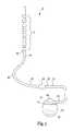
- FIG. 1illustrates a generalized therapy delivery system 10 that may be used in spinal cord stimulation (SCS), as well as other stimulation applications.
- the therapy delivery system 10generally includes an implantable pulse generator 12 , an implantable therapy delivery element 14 , which carries an array of electrodes 18 (shown exaggerated for purposes of illustration), and an optional implantable extension lead 16 . Although only one therapy delivery element 14 is shown, typically two or more therapy delivery elements 14 are used with the therapy delivery system 10 .
- the therapy delivery element 14includes elongated body 40 having a proximal end 36 and a distal end 44 .
- the elongated body 40typically has a diameter of between about 0.03 inches to 0.07 inches and a length within the range of 30 cm to 90 cm for spinal cord stimulation applications.
- the elongated body 40may be composed of a suitable electrically insulative material, such as, a polymer (e.g., polyurethane or silicone), and may be extruded from as a uni-body construction.
- proximal end 36 of the therapy delivery element 14is electrically coupled to distal end 38 of the extension lead 16 via a connector 20 , typically associated with the extension lead 16 .
- Proximal end 42 of the extension lead 16is electrically coupled to the implantable pulse generator 12 via connector 22 associated with housing 28 .
- the proximal end 36 of the therapy delivery element 14can be electrically coupled directly to the connector 20 .
- the implantable pulse generator 12includes electronic subassembly 24 (shown schematically), which includes control and pulse generation circuitry (not shown) for delivering electrical stimulation energy to the electrodes 18 of the therapy delivery element 14 in a controlled manner, and a power supply, such as battery 26 .
- the implantable pulse generator 12provides a programmable stimulation signal (e.g., in the form of electrical pulses or substantially continuous-time signals) that is delivered to target stimulation sites by electrodes 18 .
- a programmable stimulation signale.g., in the form of electrical pulses or substantially continuous-time signals
- the implantable pulse generator 12may provide the same or a different signal to the electrodes 18 .
- the implantable pulse generator 12can take the form of an implantable receiver-stimulator in which the power source for powering the implanted receiver, as well as control circuitry to command the receiver-stimulator, are contained in an external controller inductively coupled to the receiver-stimulator via an electromagnetic link.
- the implantable pulse generator 12can take the form of an external trial stimulator (ETS), which has similar pulse generation circuitry as an IPG, but differs in that it is a non-implantable device that is used on a trial basis after the therapy delivery element 14 has been implanted and prior to implantation of the IPG, to test the responsiveness of the stimulation that is to be provided.
- ETSexternal trial stimulator
- the housing 28is composed of a biocompatible material, such as for example titanium, and forms a hermetically sealed compartment containing the electronic subassembly 24 and battery 26 are protected from the body tissue and fluids.
- the connector 22is disposed in a portion of the housing 28 that is, at least initially, not sealed.
- the connector 22carries a plurality of contacts that electrically couple with respective terminals at proximal ends of the therapy delivery element 14 or extension lead 16 . Electrical conductors extend from the connector 22 and connect to the electronic subassembly 24 .
- FIG. 2is a side skeletal view of a human body illustrating spinal column.
- the sacrum regionis at a lower end of the spinal column below L-5 and adjacent the pelvic region.
- the sacrumis a triangular-shaped bone formed generally by five fused vertebrae, i.e., sacral vertebrae that are wedged dorsally between the two hip bones of the pelvic region in this region of the human anatomy.
- the lumbar regionextends from L-1 to L-5 between the sacrum region at a lower end and the thorax region (T-1 to T-12) at an upper end.
- the thorax regionextends from T-12 to T-1 at the base of the cervical region.
- the cervical regionextends from C1 to C7.
- the therapy delivery element 14is implanted in the epidural space 30 of a patient in close proximity to the dura, the outer layer that surrounds the spinal cord 32 , to deliver the intended therapeutic effects of spinal cord electrical stimulation.
- the target stimulation sites 49may be anywhere along the spinal cord 32 , such as for example proximate the sacral nerves.
- the implantable pulse generator 12is generally implanted in a surgically-made pocket either in the abdomen or above the buttocks, such as illustrated in FIG. 3 .
- the implantable pulse generator 12may, of course, also be implanted in other locations of the patient's body.
- Use of the extension lead 16facilitates locating the implantable pulse generator 12 away from the lead exit point 34 .
- the extension lead 16serves as a lead adapter if the proximal end 36 of the therapy delivery element 14 is not compatible with the connector 22 of the implantable pulse generator 12 , since different manufacturers use different connectors at the ends of their stimulation leads and are not always compatible with the connector 22 .
- the therapy delivery system 10also may include a clinician programmer 46 and a patient programmer 48 .
- Clinician programmer 46may be a handheld computing device that permits a clinician to program neurostimulation therapy for patient using input keys and a display.
- the clinicianmay specify neurostimulation parameters for use in delivery of neurostimulation therapy.
- Clinician programmer 46supports telemetry (e.g., radio frequency telemetry) with the implantable pulse generator 12 to download neurostimulation parameters and, optionally, upload operational or physiological data stored by implantable pulse generator 12 . In this manner, the clinician may periodically interrogate the implantable pulse generator 12 to evaluate efficacy and, if necessary, modify the stimulation parameters.
- patient programmer 48may be a handheld computing device. Patient programmer 48 may also include a display and input keys to allow patient to interact with patient programmer 48 and the implantable pulse generator 12 . The patient programmer 48 provides patient with an interface for control of neurostimulation therapy provided by the implantable pulse generator 12 . For example, patient may use patient programmer 48 to start, stop or adjust neurostimulation therapy. In particular, patient programmer 48 may permit patient to adjust stimulation parameters such as duration, amplitude, pulse width and pulse rate, within an adjustment range specified by the clinician via clinician programmer 48 , or select from a library of stored stimulation therapy programs.
- stimulation parameterssuch as duration, amplitude, pulse width and pulse rate
- the implantable pulse generator 12 , clinician programmer 46 , and patient programmer 48may communicate via cables or a wireless communication.
- Clinician programmer 46 and patient programmer 48may, for example, communicate via wireless communication with the implantable pulse generator 12 using RF telemetry techniques known in the art.
- Clinician programmer 46 and patient programmer 48also may communicate with each other using any of a variety of local wireless communication techniques, such as RF communication according to the 802.11 or Bluetooth specification sets, infrared communication, e.g., according to the IrDA standard, or other standard or proprietary telemetry protocols.
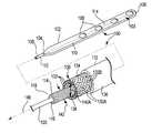
- FIG. 4Ais schematic illustration of a paddle-style therapy delivery element 100 in accordance with an embodiment of the present disclosure.
- the therapy delivery element 100includes an electrode portion 102 having proximal end 104 and distal end 106 , and a plurality of electrodes 108 .
- the electrode portion 102is a generally round or tubular paddle structure.
- a variety of other electrode portionscan be used with the present disclosure, such as disclosed in U.S. Pat. No. 6,978,180, which is incorporated by reference.
- the electrode portions 102 , 158 , 260 disclosed hereinare constructed from a polymeric material, such as for example, polyurethane or silicone, or an alloy of silicone and polyurethane, having a durometer in a range of about 20 Shore A to about 90 Shore A, as measured according to ASTM D2240.
- a polymeric materialsuch as for example, polyurethane or silicone, or an alloy of silicone and polyurethane, having a durometer in a range of about 20 Shore A to about 90 Shore A, as measured according to ASTM D2240.
- the electrodes 108may be recessed relative to surface 110 of the electrode portion 102 or are co-planar with the surface 110 . Examples include recessing the electrode 0.010 inches (0.25 mm) from the surface 110 with the electrode portion 102 .
- the electrode portion 102may have a nominal length of about 8 inches (20 cm), nominal width of about 0.15 inches (3.8 mm), and a nominal thickness of about 0.04 inches (1 mm).
- the electrode portion 102may be formed, for example, of material including polyurethane.
- the electrode portion 102may include one or more discrete radio-opaque markers 103 .
- the orientation of the electrode portion 102may be determined by noting on which side of the imaginary center line the orientation marker 103 appears to be positioned.
- the orientation marker 103may comprise radio-opaque material arranged in an asymmetric manner with respect to the width of the electrode portion 102 .
- the proximal end 104 of the electrode portion 102preferably tapers down to the diameter of elongated lead body 112 .
- the detailed illustration of the elongated lead body 112is enlarged for clarity.
- the elongated lead body 112includes stylet coil 114 with lumen 116 .
- the stylet coil 114 and lumen 116preferably extend from proximal end 118 of the elongated lead body 112 to distal end 106 of the electrode portion 102 .
- the lumen 116is sized to receive stylet 120 .
- the stylet coil 114is preferably a helical coil of an elastically deformable material, such as for example, metal or a polymeric material.
- the stylet coil 114is a helical wire with a rectangular cross section, formed from polyurethane, polysulfone, polypropylene, or PEEK.
- the helically coiled structureseparates between adjacent turns to allow stylet coil 114 to bend, either at a corner or during compression, while maintaining a substantially round cross-section.
- a metal stylet coil 114is able to substantially withstand crushing and collapse by preventing cross-sectional flattening and forcing a larger bend radius than traditional plastic stylet guides.
- the stylet coil 114is made from a wire with a diameter of about 0.012 inches to about 0.01 inches.
- a metal stylet coil 114is insulated with a polymer, such as ethylene-tetrafluoroethylene (ETFE), polytetrafluoroethylene (PTFE), modified PTFE, and polyimide, polyurethane, silicone, or polyester.
- the stylet coil 114is electrically inactive.
- the stylet coil 114can carry signals or acts as a ground plane for the electrodes 108 .
- the stylet 120provides steerability and rigidity, while the stylet coil 114 provides column strength to both the electrode portion 102 and the elongated lead body 112 to facilitate insertion and removal of the therapy delivery element 100 from a living body.
- the stylet coil 114protects the electrode portion 102 and conductor assembly 130 during insertion and removal of the stylet 120 .
- the stylet 120can include one or more bends that steer or direct the more flexible elongated lead portion 112 and electrode portion 102 to the target location.
- the stylet coil 114also increases resistant to flex fatigue, buckling fatigue, axial displacement, kinking and crush, of the elongated lead body 112 , while still permitting elongation or stretch of the elongated lead body 112 .
- Conductor assembly 130extends through elongated lead body 112 to at least the proximal end 104 of the electrode portion 102 .
- the conductor assembly 130includes a plurality of electrical conductors 132 arranged in a tubular, braided configuration 134 .
- the conductor assembly 130is a 2-over/2-under braid.
- Various other braid structuresare disclosed in U.S. Pat. Publication No. 2008/0210328 (Henry), which is hereby incorporated by reference.
- the electrical conductors 132are fluoropolymer insulated 0.005 diameter MP35N wires, which is a biocompatible, nonmagnetic, nickel-cobalt-chromium-molybdenum alloy with high strength and corrosion resistance, with gold or silver cores to improve conductance.
- Low durometer insulator 136extends around the conductor assembly 130 .
- the insulator 136can be an extruded or molded material, such as for example, polyurethane or silicone, or an alloy of silicone and polyurethane.
- the insulators 136 of elongated lead bodies 112 , 160 , 258 , 320 disclosed hereinhave a durometer in a range of about 55 Shore A to about 75 Shore A, and alternatively about 30 Shore A to about 60 Shore A, as measured according to ASTM D2240.
- the electrical conductors 132 Aare braided with non-conductive elements 132 B.
- the electrical conductors 132 Aare all oriented generally parallel within the braided structure, and the non-conductive elements 132 B are oriented in the other direction. Consequently, the electrical conductors 132 A do not cross over each other.
- the electrical conductors 132are electrically coupled to the electrodes 108 in a manner known in the art.
- the braided configuration 134terminates at the proximal end 104 of the electrode portion 102 , and the individual electrical conductors 132 continue through the electrode portion 102 to the electrodes 108 .
- the braided portioncontinues along the stylet coil 114 for all or a portion of the length of the electrode portion 102 .
- the braided configuration 134is a complex structure or pattern formed by intertwining the electrical conductors 132 .
- Each electrical conductor 132is preferably functionally equivalent in zigzagging forward through the overlapping mass of the other conductors 132 .
- the braided configuration 134preferably includes lumen 138 that preferably has an inside diameter 140 A greater than outside diameter 142 of the stylet coil 114 . Consequently, gap 144 permits the braided configuration 134 to neck-down during elongation or stretching of the conductor assembly 130 .
- the conductor assembly 130is not attached to the stylet coil 114 , except at the proximal ends 104 , 118 .
- relaxed configuration 146 illustrated in FIG. 4Athe individual electrical conductors 132 are oriented at an angle of about 20 degrees to about 45 degrees relative to central axis 148 of the elongated lead body 112 .
- FIG. 4Billustrates the elongated lead body 112 in an elongated configuration 113 .
- the conductor assembly 130necks down to a smaller diameter 140 B, permitting an increase in overall length of the elongated lead body 112 (see, e.g., FIG. 9 ), without damaging the individual conductors 132 .
- the individual conductors 132rotate toward alignment with central axis 148 of the elongated lead body 112 .
- the individual conductors 132form an angle with the central axis 148 of about 0 degrees to about 25 degrees.
- the gap 144is reduced or eliminated.
- outside diameter 145 of the insulator 136also decreases in the elongated configuration 113 .
- the braided configuration 134permits the conductor assembly 130 to elongate under tension, without damaging the individual electrical conductors 132 . Elongation of the conductor assembly 130 reduces mechanical loading on tissue anchor points, implantable lead extensions 16 , the implantable therapy delivery element 100 , and the implantable pulse generator 12 during typical patient movement.
- the braided configuration 134 leadmay improve resistance to flex fatigue, buckling fatigue, kinking, and crush.
- the braided configuration 134exhibits reduced axial stiffness.
- the target axial stiffnessmay be achieved by selection of appropriate materials, insulator 136 , and braid configuration 134 for the electrical conductors 132 .
- a reduced axial stiffness in the above rangepromotes increased stretchability in the elongated lead body 112 to better accommodate changes in length along the patient's body.
- the enhanced stretchabilitymay substantially eliminate lead failure due to fractures or electrical shorting, axial migration of electrodes coupled to the lead body, anchor damage, and/or tissue damage at anchor points.
- FIG. 5is schematic illustration of an alternate paddle-style therapy delivery element 150 with a plurality of rows 152 A, 152 B of electrodes 154 , in accordance with an embodiment of the present disclosure.
- Proximal end 156 of electrode portion 158includes a pair of elongated lead bodies 160 A, 160 B (“ 160 ”). The detailed illustration of the elongated lead bodies 160 are enlarged for clarity.
- Each elongated lead body 160includes stylet coil 162 with lumen 164 that extends to distal end 166 of electrode portion 158 .
- Braided electrical conductors 168 A, 168 Bare electrically coupled to row 152 A, 152 B of the electrodes 154 , respectively, as discussed above.
- Stylets 170 A, 170 Bcan be used simultaneously to steer the therapy delivery element 150 to the desired location in the patient.
- FIG. 6is a schematic illustration of a ring-electrode therapy delivery element 200 with an electrode portion 212 and an elongated lead body 202 in accordance with an embodiment of the present disclosure.
- the electrode portion 212include a plurality of ring-electrodes 214 .
- the stylet coil 204 and associated lumen 206preferably extend to distal end 208 of the therapy delivery element 200 .
- Braided electrical conductors 210are extend around the stylet coil 204 , substantially as discussed above.
- FIGS. 7 through 9are schematic illustrations of a method of implanting a therapy delivery element 250 in accordance with an embodiment of the present disclosure.
- Stylet 252is inserted in lumen of stylet coil 254 .
- the stylet 252extends from the proximal end 256 of the elongated lead body 258 to the distal end 260 of the therapy delivery element 250 .
- the elongated lead body 258includes a conductor assembly with braided electrical conductors as discussed herein (see e.g., FIG. 4 ).
- the stylet 252provides stiffness to the elongated lead body 258 , while the stylet coil 254 provides column strength.
- the stylet 252is removed.
- the elongated lead body 258is now highly flexible and stretchable.
- the elongated lead body 258is in stretched configuration 270 , resulting from tension force 272 created within the living body. During stretching, the braided conductors necks down to provide increase overall length of the conductor assembly, without damaging the individual conductors.
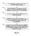
- FIG. 10is a flow diagram of a method of implanting a neurostimulation system within a living body in accordance with an embodiment of the present disclosure.
- a styletis inserted in lumen of stylet coil of the therapy delivery element ( 300 ).
- the physiciangrasps the elongated lead body and/or a stylet hub to steer the therapy delivery element to the desired location in the living body ( 302 ).
- the styletis removed once the therapy delivery element is positioned ( 304 ).
- Proximal ends of the therapy delivery elementsare electrically coupled to an implantable pulse generator implanted in the living body ( 306 ).
- a braided conductors assemblyextending around the style coil in the elongated lead body necks down to provide increase overall length of the conductor assembly, without damaging the individual conductors ( 308 ).
- FIG. 11illustrates an embodiment of lead extension 16 (illustrated in FIG. 1 ) with a plurality of braided electrical conductors in accordance with an embodiment of the present disclosure.
- the distal end 38 of the lead extension 16includes connector 20 and proximal end 42 includes contact rings that electrically couple with connector 22 .
- Elongated lead body 320includes a plurality of the electrical conductors 132 arranged in a tubular, braided configuration 134 .
- the style coil 114may optionally be included in the elongated lead body 320 in order to receive stylet 120 for certain applications. Alternatively, the stylet coil 114 and stylet 120 may be omitted for some applications.
Landscapes
- Health & Medical Sciences (AREA)
- Nuclear Medicine, Radiotherapy & Molecular Imaging (AREA)
- Animal Behavior & Ethology (AREA)
- Veterinary Medicine (AREA)
- Cardiology (AREA)
- Heart & Thoracic Surgery (AREA)
- Engineering & Computer Science (AREA)
- Public Health (AREA)
- Radiology & Medical Imaging (AREA)
- Biomedical Technology (AREA)
- Life Sciences & Earth Sciences (AREA)
- General Health & Medical Sciences (AREA)
- Neurology (AREA)
- Neurosurgery (AREA)
- Orthopedic Medicine & Surgery (AREA)
- Electrotherapy Devices (AREA)
Abstract
Description
Claims (22)
Priority Applications (3)
| Application Number | Priority Date | Filing Date | Title |
|---|---|---|---|
| US13/045,908US8543223B2 (en) | 2011-03-11 | 2011-03-11 | Implantable lead with braided conductors |
| US14/019,653US8738153B2 (en) | 2011-03-11 | 2013-09-06 | Implantable lead with braided conductors |
| US14/258,365US9084881B2 (en) | 2011-03-11 | 2014-04-22 | Implantable lead with braided conductors |
Applications Claiming Priority (1)
| Application Number | Priority Date | Filing Date | Title |
|---|---|---|---|
| US13/045,908US8543223B2 (en) | 2011-03-11 | 2011-03-11 | Implantable lead with braided conductors |
Related Child Applications (1)
| Application Number | Title | Priority Date | Filing Date |
|---|---|---|---|
| US14/019,653DivisionUS8738153B2 (en) | 2011-03-11 | 2013-09-06 | Implantable lead with braided conductors |
Publications (2)
| Publication Number | Publication Date |
|---|---|
| US20120232625A1 US20120232625A1 (en) | 2012-09-13 |
| US8543223B2true US8543223B2 (en) | 2013-09-24 |
Family
ID=46796677
Family Applications (3)
| Application Number | Title | Priority Date | Filing Date |
|---|---|---|---|
| US13/045,908Active2031-12-13US8543223B2 (en) | 2011-03-11 | 2011-03-11 | Implantable lead with braided conductors |
| US14/019,653ActiveUS8738153B2 (en) | 2011-03-11 | 2013-09-06 | Implantable lead with braided conductors |
| US14/258,365ActiveUS9084881B2 (en) | 2011-03-11 | 2014-04-22 | Implantable lead with braided conductors |
Family Applications After (2)
| Application Number | Title | Priority Date | Filing Date |
|---|---|---|---|
| US14/019,653ActiveUS8738153B2 (en) | 2011-03-11 | 2013-09-06 | Implantable lead with braided conductors |
| US14/258,365ActiveUS9084881B2 (en) | 2011-03-11 | 2014-04-22 | Implantable lead with braided conductors |
Country Status (1)
| Country | Link |
|---|---|
| US (3) | US8543223B2 (en) |
Cited By (30)
| Publication number | Priority date | Publication date | Assignee | Title |
|---|---|---|---|---|
| US20140005599A1 (en)* | 2012-06-29 | 2014-01-02 | Greatbatch Ltd. | Dynamic coil for implantable stimulation leads |
| US9308378B2 (en) | 2013-05-03 | 2016-04-12 | Alfred E. Mann Foundation For Scientific Research | Implant recharger handshaking system and method |
| US9427574B2 (en) | 2014-08-15 | 2016-08-30 | Axonics Modulation Technologies, Inc. | Implantable lead affixation structure for nerve stimulation to alleviate bladder dysfunction and other indication |
| US9433779B2 (en) | 2013-05-03 | 2016-09-06 | Alfred E. Mann Foundation For Scientific Research | Multi-branch stimulation electrode for subcutaneous field stimulation |
| US9446241B2 (en) | 2013-03-15 | 2016-09-20 | Alfred E. Mann Foundation For Scientific Research | Current sensing multiple output current stimulators |
| US9517338B1 (en) | 2016-01-19 | 2016-12-13 | Axonics Modulation Technologies, Inc. | Multichannel clip device and methods of use |
| US9533155B2 (en) | 2014-08-15 | 2017-01-03 | Axonics Modulation Technologies, Inc. | Methods for determining neurostimulation electrode configurations based on neural localization |
| US9555246B2 (en) | 2014-08-15 | 2017-01-31 | Axonics Modulation Technologies, Inc. | Electromyographic lead positioning and stimulation titration in a nerve stimulation system for treatment of overactive bladder |
| US9675807B2 (en) | 2013-05-03 | 2017-06-13 | Alfred E. Mann Foundation For Scientific Research | High reliability wire welding for implantable devices |
| US9682237B2 (en) | 2013-03-15 | 2017-06-20 | Alfred E. Mann Foundation For Scientific Research | High voltage monitoring successive approximation analog to digital converter |
| US9700731B2 (en) | 2014-08-15 | 2017-07-11 | Axonics Modulation Technologies, Inc. | Antenna and methods of use for an implantable nerve stimulator |
| US9728981B2 (en) | 2012-08-31 | 2017-08-08 | Alfred E. Mann Foundation For Scientific Research | Feedback controlled coil driver for inductive power transfer |
| US9780596B2 (en) | 2013-07-29 | 2017-10-03 | Alfred E. Mann Foundation For Scientific Research | Microprocessor controlled class E driver |
| US9802051B2 (en) | 2014-08-15 | 2017-10-31 | Axonics Modulation Technologies, Inc. | External pulse generator device and associated methods for trial nerve stimulation |
| US9855436B2 (en) | 2013-07-29 | 2018-01-02 | Alfred E. Mann Foundation For Scientific Research | High efficiency magnetic link for implantable devices |
| US9895546B2 (en) | 2015-01-09 | 2018-02-20 | Axonics Modulation Technologies, Inc. | Patient remote and associated methods of use with a nerve stimulation system |
| US9925381B2 (en) | 2015-07-10 | 2018-03-27 | Axonics Modulation Technologies, Inc. | Implantable nerve stimulator having internal electronics without ASIC and methods of use |
| US10092762B2 (en) | 2014-08-15 | 2018-10-09 | Axonics Modulation Technologies, Inc. | Integrated electromyographic clinician programmer for use with an implantable neurostimulator |
| US10195423B2 (en) | 2016-01-19 | 2019-02-05 | Axonics Modulation Technologies, Inc. | Multichannel clip device and methods of use |
| US10376704B2 (en) | 2016-02-12 | 2019-08-13 | Axonics Modulation Technologies, Inc. | External pulse generator device and associated methods for trial nerve stimulation |
| US10561835B2 (en) | 2006-10-31 | 2020-02-18 | Medtronic, Inc. | Implantable medical lead with threaded fixation |
| US10603500B2 (en) | 2016-01-29 | 2020-03-31 | Axonics Modulation Technologies, Inc. | Methods and systems for frequency adjustment to optimize charging of implantable neurostimulator |
| US10682521B2 (en) | 2014-08-15 | 2020-06-16 | Axonics Modulation Technologies, Inc. | Attachment devices and associated methods of use with a nerve stimulation charging device |
| US11110283B2 (en) | 2018-02-22 | 2021-09-07 | Axonics, Inc. | Neurostimulation leads for trial nerve stimulation and methods of use |
| WO2022006317A1 (en)* | 2020-06-30 | 2022-01-06 | Juad Nextgen Neuroend, Llc | Transcatheter electroctode array and use thereof |
| US11439829B2 (en) | 2019-05-24 | 2022-09-13 | Axonics, Inc. | Clinician programmer methods and systems for maintaining target operating temperatures |
| US11484723B2 (en) | 2015-01-09 | 2022-11-01 | Axonics, Inc. | Attachment devices and associated methods of use with a nerve stimulation charging device |
| US11642537B2 (en) | 2019-03-11 | 2023-05-09 | Axonics, Inc. | Charging device with off-center coil |
| US11848090B2 (en) | 2019-05-24 | 2023-12-19 | Axonics, Inc. | Trainer for a neurostimulator programmer and associated methods of use with a neurostimulation system |
| US12420103B1 (en) | 2020-08-20 | 2025-09-23 | Axonics, Inc. | Neurostimulation leads with reduced current leakage |
Families Citing this family (7)
| Publication number | Priority date | Publication date | Assignee | Title |
|---|---|---|---|---|
| US20130123912A1 (en)* | 2011-11-15 | 2013-05-16 | Boston Scientific Scimed, Inc. | Medical device with nosecone and nosecone tube extension |
| US8644953B1 (en) | 2012-08-10 | 2014-02-04 | Greatbatch Ltd. | Lead with braided reinforcement |
| US9775984B2 (en) | 2014-08-01 | 2017-10-03 | Nuvectra Corporation | Apparatus with unencapsulated reinforcement |
| KR101731231B1 (en)* | 2015-07-31 | 2017-04-28 | 재단법인 오송첨단의료산업진흥재단 | Implantable hybrid lead and a method of manufacturing the same |
| WO2019060058A1 (en) | 2017-09-21 | 2019-03-28 | Medtronic, Inc. | Imaging markers for stimulator leads |
| US12257430B2 (en)* | 2020-04-16 | 2025-03-25 | Medtronic, Inc. | Implantable medical lead systems and adapters |
| WO2023288074A1 (en)* | 2021-07-15 | 2023-01-19 | Spr Therapeutics, Inc. | Fracture resistant stimulation lead |
Citations (17)
| Publication number | Priority date | Publication date | Assignee | Title |
|---|---|---|---|---|
| US5643330A (en) | 1994-01-24 | 1997-07-01 | Medtronic, Inc. | Multichannel apparatus for epidural spinal cord stimulation |
| US6249707B1 (en) | 1999-04-30 | 2001-06-19 | Medtronic, Inc. | Apparatus and method for percutaneous implant of a paddle style lead |
| US6308103B1 (en) | 1999-09-13 | 2001-10-23 | Medtronic Inc. | Self-centering epidural spinal cord lead and method |
| US6968237B2 (en)* | 2002-05-22 | 2005-11-22 | Pacesetter, Inc. | Implantable coronary sinus lead and lead system |
| US20060089696A1 (en)* | 2004-10-21 | 2006-04-27 | Medtronic, Inc. | Implantable medical lead with reinforced outer jacket |
| US20070168007A1 (en)* | 2005-01-11 | 2007-07-19 | Advanced Bionics Corporation | Lead Assembly and Method of Making Same |
| US20080147155A1 (en)* | 2006-12-19 | 2008-06-19 | Quan Emerteq Corp. | Braided Electrical Lead |
| US20090005844A1 (en) | 2007-06-27 | 2009-01-01 | Quan Emerteq Corp. | Percutaneous electrode array and system |
| US20090099441A1 (en)* | 2005-09-08 | 2009-04-16 | Drexel University | Braided electrodes |
| US20090270957A1 (en) | 2008-04-25 | 2009-10-29 | Boston Scientific Neuromodulation Corporation | Stimulation system with percutaneously deliverable paddle lead and methods of making and using |
| US20100042109A1 (en) | 2008-08-12 | 2010-02-18 | Boston Scientific Neuromodulation Corporation | Stylet for guiding leads of implantable electric stimulation systems and methods of making and using |
| US20100070012A1 (en) | 2008-09-15 | 2010-03-18 | Boston Scientific Neuromodulation Corporation | Lead connection system for an implantable electrical stimulation system and methods for making and using the systems |
| US7792591B2 (en) | 2005-06-09 | 2010-09-07 | Medtronic, Inc. | Introducer for therapy delivery elements |
| US7797057B2 (en) | 2002-10-23 | 2010-09-14 | Medtronic, Inc. | Medical paddle lead and method for spinal cord stimulation |
| US7798864B2 (en) | 2008-03-12 | 2010-09-21 | Boston Scientific Neuromodulation Corporation | Low-profile connector for a neurostimulation lead |
| US7831311B2 (en) | 2004-10-21 | 2010-11-09 | Medtronic, Inc. | Reduced axial stiffness implantable medical lead |
| US20100312319A1 (en) | 2009-06-04 | 2010-12-09 | Boston Scientific Neuromodulation Corporation | Three-piece button anchor and methods and devices using the anchor |
- 2011
- 2011-03-11USUS13/045,908patent/US8543223B2/enactiveActive
- 2013
- 2013-09-06USUS14/019,653patent/US8738153B2/enactiveActive
- 2014
- 2014-04-22USUS14/258,365patent/US9084881B2/enactiveActive
Patent Citations (17)
| Publication number | Priority date | Publication date | Assignee | Title |
|---|---|---|---|---|
| US5643330A (en) | 1994-01-24 | 1997-07-01 | Medtronic, Inc. | Multichannel apparatus for epidural spinal cord stimulation |
| US6249707B1 (en) | 1999-04-30 | 2001-06-19 | Medtronic, Inc. | Apparatus and method for percutaneous implant of a paddle style lead |
| US6308103B1 (en) | 1999-09-13 | 2001-10-23 | Medtronic Inc. | Self-centering epidural spinal cord lead and method |
| US6968237B2 (en)* | 2002-05-22 | 2005-11-22 | Pacesetter, Inc. | Implantable coronary sinus lead and lead system |
| US7797057B2 (en) | 2002-10-23 | 2010-09-14 | Medtronic, Inc. | Medical paddle lead and method for spinal cord stimulation |
| US20060089696A1 (en)* | 2004-10-21 | 2006-04-27 | Medtronic, Inc. | Implantable medical lead with reinforced outer jacket |
| US7831311B2 (en) | 2004-10-21 | 2010-11-09 | Medtronic, Inc. | Reduced axial stiffness implantable medical lead |
| US20070168007A1 (en)* | 2005-01-11 | 2007-07-19 | Advanced Bionics Corporation | Lead Assembly and Method of Making Same |
| US7792591B2 (en) | 2005-06-09 | 2010-09-07 | Medtronic, Inc. | Introducer for therapy delivery elements |
| US20090099441A1 (en)* | 2005-09-08 | 2009-04-16 | Drexel University | Braided electrodes |
| US20080147155A1 (en)* | 2006-12-19 | 2008-06-19 | Quan Emerteq Corp. | Braided Electrical Lead |
| US20090005844A1 (en) | 2007-06-27 | 2009-01-01 | Quan Emerteq Corp. | Percutaneous electrode array and system |
| US7798864B2 (en) | 2008-03-12 | 2010-09-21 | Boston Scientific Neuromodulation Corporation | Low-profile connector for a neurostimulation lead |
| US20090270957A1 (en) | 2008-04-25 | 2009-10-29 | Boston Scientific Neuromodulation Corporation | Stimulation system with percutaneously deliverable paddle lead and methods of making and using |
| US20100042109A1 (en) | 2008-08-12 | 2010-02-18 | Boston Scientific Neuromodulation Corporation | Stylet for guiding leads of implantable electric stimulation systems and methods of making and using |
| US20100070012A1 (en) | 2008-09-15 | 2010-03-18 | Boston Scientific Neuromodulation Corporation | Lead connection system for an implantable electrical stimulation system and methods for making and using the systems |
| US20100312319A1 (en) | 2009-06-04 | 2010-12-09 | Boston Scientific Neuromodulation Corporation | Three-piece button anchor and methods and devices using the anchor |
Cited By (70)
| Publication number | Priority date | Publication date | Assignee | Title |
|---|---|---|---|---|
| US10561835B2 (en) | 2006-10-31 | 2020-02-18 | Medtronic, Inc. | Implantable medical lead with threaded fixation |
| US20140005599A1 (en)* | 2012-06-29 | 2014-01-02 | Greatbatch Ltd. | Dynamic coil for implantable stimulation leads |
| US9427571B2 (en)* | 2012-06-29 | 2016-08-30 | Nuvectra Corporation | Dynamic coil for implantable stimulation leads |
| US10661077B2 (en) | 2012-06-29 | 2020-05-26 | Nuvectra Corporation | Manufacturing method of a dynamic coil for implantable stimulation leads |
| US9728981B2 (en) | 2012-08-31 | 2017-08-08 | Alfred E. Mann Foundation For Scientific Research | Feedback controlled coil driver for inductive power transfer |
| US9981130B2 (en) | 2013-03-15 | 2018-05-29 | Alfred E. Mann Foundation For Scientific Research | Current sensing multiple output current stimulators |
| US9446241B2 (en) | 2013-03-15 | 2016-09-20 | Alfred E. Mann Foundation For Scientific Research | Current sensing multiple output current stimulators |
| US11338144B2 (en) | 2013-03-15 | 2022-05-24 | Alfred E. Mann Foundation For Scientific Research | Current sensing multiple output current stimulators |
| US9682237B2 (en) | 2013-03-15 | 2017-06-20 | Alfred E. Mann Foundation For Scientific Research | High voltage monitoring successive approximation analog to digital converter |
| US10603495B2 (en) | 2013-03-15 | 2020-03-31 | The Alfred E. Mann Foundation For Scientific Research | Current sensing multiple output current stimulators |
| US9675807B2 (en) | 2013-05-03 | 2017-06-13 | Alfred E. Mann Foundation For Scientific Research | High reliability wire welding for implantable devices |
| US9433779B2 (en) | 2013-05-03 | 2016-09-06 | Alfred E. Mann Foundation For Scientific Research | Multi-branch stimulation electrode for subcutaneous field stimulation |
| US9308378B2 (en) | 2013-05-03 | 2016-04-12 | Alfred E. Mann Foundation For Scientific Research | Implant recharger handshaking system and method |
| US9789325B2 (en) | 2013-05-03 | 2017-10-17 | Alfred E. Mann Foundation For Scientific Research | Implant recharger handshaking system and method |
| US10029090B2 (en) | 2013-05-03 | 2018-07-24 | Alfred E. Mann Foundation For Scientific Research | Multi-branch stimulation electrode for subcutaneous field stimulation |
| US10971950B2 (en) | 2013-07-29 | 2021-04-06 | The Alfred E. Mann Foundation For Scientific Research | Microprocessor controlled class E driver |
| US11722007B2 (en) | 2013-07-29 | 2023-08-08 | The Alfred E. Mann Foundation For Scientific Rsrch | Microprocessor controlled class E driver |
| US9780596B2 (en) | 2013-07-29 | 2017-10-03 | Alfred E. Mann Foundation For Scientific Research | Microprocessor controlled class E driver |
| US10449377B2 (en) | 2013-07-29 | 2019-10-22 | The Alfred E. Mann Foundation For Scientific Research | High efficiency magnetic link for implantable devices |
| US10447083B2 (en) | 2013-07-29 | 2019-10-15 | The Alfred E. Mann Foundation For Scientific Research | Microprocessor controlled class E driver |
| US9855436B2 (en) | 2013-07-29 | 2018-01-02 | Alfred E. Mann Foundation For Scientific Research | High efficiency magnetic link for implantable devices |
| US10478619B2 (en) | 2014-08-15 | 2019-11-19 | Axonics Modulation Technologies, Inc. | Implantable lead affixation structure for nerve stimulation to alleviate bladder dysfunction and other indication |
| US11116985B2 (en) | 2014-08-15 | 2021-09-14 | Axonics, Inc. | Clinician programmer for use with an implantable neurostimulation lead |
| US11730411B2 (en) | 2014-08-15 | 2023-08-22 | Axonics, Inc. | Methods for determining neurostimulation electrode configurations based on neural localization |
| US9855423B2 (en) | 2014-08-15 | 2018-01-02 | Axonics Modulation Technologies, Inc. | Systems and methods for neurostimulation electrode configurations based on neural localization |
| US10092762B2 (en) | 2014-08-15 | 2018-10-09 | Axonics Modulation Technologies, Inc. | Integrated electromyographic clinician programmer for use with an implantable neurostimulator |
| US9427574B2 (en) | 2014-08-15 | 2016-08-30 | Axonics Modulation Technologies, Inc. | Implantable lead affixation structure for nerve stimulation to alleviate bladder dysfunction and other indication |
| US11497916B2 (en) | 2014-08-15 | 2022-11-15 | Axonics, Inc. | Electromyographic lead positioning and stimulation titration in a nerve stimulation system for treatment of overactive bladder |
| US11389659B2 (en) | 2014-08-15 | 2022-07-19 | Axonics, Inc. | External pulse generator device and associated methods for trial nerve stimulation |
| US11213675B2 (en) | 2014-08-15 | 2022-01-04 | Axonics, Inc. | Implantable lead affixation structure for nerve stimulation to alleviate bladder dysfunction and other indication |
| US10406369B2 (en) | 2014-08-15 | 2019-09-10 | Axonics Modulation Technologies, Inc. | Electromyographic lead positioning and stimulation titration in a nerve stimulation system for treatment of overactive bladder |
| US9802051B2 (en) | 2014-08-15 | 2017-10-31 | Axonics Modulation Technologies, Inc. | External pulse generator device and associated methods for trial nerve stimulation |
| US9802038B2 (en) | 2014-08-15 | 2017-10-31 | Axonics Modulation Technologies, Inc. | Implantable lead affixation structure for nerve stimulation to alleviate bladder dysfunction and other indication |
| US9533155B2 (en) | 2014-08-15 | 2017-01-03 | Axonics Modulation Technologies, Inc. | Methods for determining neurostimulation electrode configurations based on neural localization |
| US9700731B2 (en) | 2014-08-15 | 2017-07-11 | Axonics Modulation Technologies, Inc. | Antenna and methods of use for an implantable nerve stimulator |
| US10589103B2 (en) | 2014-08-15 | 2020-03-17 | Axonics Modulation Technologies, Inc. | External pulse generator device and associated methods for trial nerve stimulation |
| US9561372B2 (en) | 2014-08-15 | 2017-02-07 | Axonics Modulation Technologies, Inc. | Electromyographic lead positioning and stimulation titration in a nerve stimulation system for treatment of overactive bladder |
| US10729903B2 (en) | 2014-08-15 | 2020-08-04 | Axonics Modulation Technologies, Inc. | Methods for determining neurostimulation electrode configurations based on neural localization |
| US9555246B2 (en) | 2014-08-15 | 2017-01-31 | Axonics Modulation Technologies, Inc. | Electromyographic lead positioning and stimulation titration in a nerve stimulation system for treatment of overactive bladder |
| US10682521B2 (en) | 2014-08-15 | 2020-06-16 | Axonics Modulation Technologies, Inc. | Attachment devices and associated methods of use with a nerve stimulation charging device |
| US11478648B2 (en) | 2015-01-09 | 2022-10-25 | Axonics, Inc. | Antenna and methods of use for an implantable nerve stimulator |
| US10105542B2 (en) | 2015-01-09 | 2018-10-23 | Axonics Modulation Technologies, Inc. | Patient remote and associated methods of use with a nerve stimulation system |
| US9895546B2 (en) | 2015-01-09 | 2018-02-20 | Axonics Modulation Technologies, Inc. | Patient remote and associated methods of use with a nerve stimulation system |
| US9770596B2 (en) | 2015-01-09 | 2017-09-26 | Axonics Modulation Technologies, Inc. | Antenna and methods of use for an implantable nerve stimulator |
| US11484723B2 (en) | 2015-01-09 | 2022-11-01 | Axonics, Inc. | Attachment devices and associated methods of use with a nerve stimulation charging device |
| US10722721B2 (en) | 2015-01-09 | 2020-07-28 | Axonics Modulation Technologies, Inc. | Antenna and methods of use for an implantable nerve stimulator |
| US10384067B2 (en) | 2015-01-09 | 2019-08-20 | Axonics Modulation Technologies, Inc. | Patient remote and associated methods of use with a nerve stimulation system |
| US11123569B2 (en) | 2015-01-09 | 2021-09-21 | Axonics, Inc. | Patient remote and associated methods of use with a nerve stimulation system |
| US11766568B2 (en) | 2015-07-10 | 2023-09-26 | Axonics, Inc. | Implantable nerve stimulator having internal electronics without ASIC and methods of use |
| US10850104B2 (en) | 2015-07-10 | 2020-12-01 | Axonics Modulation Technologies, Inc. | Implantable nerve stimulator having internal electronics without ASIC and methods of use |
| US9925381B2 (en) | 2015-07-10 | 2018-03-27 | Axonics Modulation Technologies, Inc. | Implantable nerve stimulator having internal electronics without ASIC and methods of use |
| US10195423B2 (en) | 2016-01-19 | 2019-02-05 | Axonics Modulation Technologies, Inc. | Multichannel clip device and methods of use |
| US9517338B1 (en) | 2016-01-19 | 2016-12-13 | Axonics Modulation Technologies, Inc. | Multichannel clip device and methods of use |
| US11083903B2 (en) | 2016-01-29 | 2021-08-10 | Axonics, Inc. | Methods and systems for frequency adjustment to optimize charging of implantable neurostimulator |
| US11602638B2 (en) | 2016-01-29 | 2023-03-14 | Axonics, Inc. | Methods and systems for frequency adjustment to optimize charging of implantable neurostimulator |
| US10603500B2 (en) | 2016-01-29 | 2020-03-31 | Axonics Modulation Technologies, Inc. | Methods and systems for frequency adjustment to optimize charging of implantable neurostimulator |
| US12083349B2 (en) | 2016-01-29 | 2024-09-10 | Axonics, Inc. | Methods and systems for frequency adjustment to optimize charging of implantable neurostimulator |
| US10376704B2 (en) | 2016-02-12 | 2019-08-13 | Axonics Modulation Technologies, Inc. | External pulse generator device and associated methods for trial nerve stimulation |
| US11260236B2 (en) | 2016-02-12 | 2022-03-01 | Axonics, Inc. | External pulse generator device and affixation device for trial nerve stimulation and methods of use |
| US12226643B2 (en) | 2016-02-12 | 2025-02-18 | Axonics, Inc. | External pulse generator device and affixation device for trial nerve stimulation and methods of use |
| US11511122B2 (en) | 2018-02-22 | 2022-11-29 | Axonics, Inc. | Neurostimulation leads for trial nerve stimulation and methods of use |
| US11110283B2 (en) | 2018-02-22 | 2021-09-07 | Axonics, Inc. | Neurostimulation leads for trial nerve stimulation and methods of use |
| US12042662B2 (en) | 2018-02-22 | 2024-07-23 | Axonics, Inc. | Neurostimulation leads for trial nerve stimulation and methods of use |
| US11642537B2 (en) | 2019-03-11 | 2023-05-09 | Axonics, Inc. | Charging device with off-center coil |
| US11439829B2 (en) | 2019-05-24 | 2022-09-13 | Axonics, Inc. | Clinician programmer methods and systems for maintaining target operating temperatures |
| US11848090B2 (en) | 2019-05-24 | 2023-12-19 | Axonics, Inc. | Trainer for a neurostimulator programmer and associated methods of use with a neurostimulation system |
| US11931564B2 (en) | 2020-06-30 | 2024-03-19 | Vonova Inc. | Transcatheter electrode array and use thereof |
| US11806523B2 (en) | 2020-06-30 | 2023-11-07 | Vonova Inc. | Transcatheter electrode array and use thereof |
| WO2022006317A1 (en)* | 2020-06-30 | 2022-01-06 | Juad Nextgen Neuroend, Llc | Transcatheter electroctode array and use thereof |
| US12420103B1 (en) | 2020-08-20 | 2025-09-23 | Axonics, Inc. | Neurostimulation leads with reduced current leakage |
Also Published As
| Publication number | Publication date |
|---|---|
| US9084881B2 (en) | 2015-07-21 |
| US20140012357A1 (en) | 2014-01-09 |
| US8738153B2 (en) | 2014-05-27 |
| US20120232625A1 (en) | 2012-09-13 |
| US20140228920A1 (en) | 2014-08-14 |
Similar Documents
| Publication | Publication Date | Title |
|---|---|---|
| US9084881B2 (en) | Implantable lead with braided conductors | |
| US11160974B2 (en) | Neurostimulation lead with stiffened proximal array | |
| US8560084B2 (en) | Lead body with inner and outer co-axial coils | |
| US10661077B2 (en) | Manufacturing method of a dynamic coil for implantable stimulation leads | |
| EP2593178B1 (en) | Tunneling tool for implantable leads | |
| US9026227B2 (en) | Anchor sleeve for implantable lead | |
| US20140005754A1 (en) | Braided lead with embedded fixation structures | |
| US20170333702A1 (en) | Systems and method for anchoring a lead for neurostimulation of a target anatomy | |
| US20090216306A1 (en) | Temporary neurostimulation lead identification device | |
| US10518083B2 (en) | Lead with braided reinforcement | |
| US9067056B2 (en) | Lead spacer tool | |
| EP2497434B1 (en) | Epidural needle for spinal cord stimulation | |
| US9320888B2 (en) | Adjustable wire length stylet handle |
Legal Events
| Date | Code | Title | Description |
|---|---|---|---|
| AS | Assignment | Owner name:GREATBATCH LTD., NEW YORK Free format text:ASSIGNMENT OF ASSIGNORS INTEREST;ASSIGNORS:SAGE, SHAHN S.;SWOYER, JOHN;GEROY, JESSE;REEL/FRAME:025962/0630 Effective date:20110307 | |
| AS | Assignment | Owner name:GREATBATCH LTD., NEW YORK Free format text:CORRECTIVE ASSIGNMENT TO CORRECT THE ADDRESS CHANGE PREVIOUSLY RECORDED ON REEL 025962 FRAME 0630. ASSIGNOR(S) HEREBY CONFIRMS THE OLD ADDRESS: 10,000 WEHRLE DRIVE BUFFALO, NEW YORK 14031 NEW ADDRESS: 10,000 WEHRLE DRIVE CLARENCE, NEW YORK 14031;ASSIGNORS:SAGE, SHAHN;SWOYER, JOHN;GEROY, JESSE;REEL/FRAME:027690/0657 Effective date:20110307 | |
| STCF | Information on status: patent grant | Free format text:PATENTED CASE | |
| CC | Certificate of correction | ||
| AS | Assignment | Owner name:MANUFACTURERS AND TRADERS TRUST COMPANY, NEW YORK Free format text:SECURITY INTEREST;ASSIGNORS:GREATBATCH, INC.;GREATBATCH LTD.;ELECTROCHEM SOLUTIONS, INC.;AND OTHERS;REEL/FRAME:036980/0482 Effective date:20151027 | |
| AS | Assignment | Owner name:QIG GROUP, LLC, NEW YORK Free format text:ASSIGNMENT OF ASSIGNORS INTEREST;ASSIGNOR:GREATBATCH LTD.;REEL/FRAME:037810/0051 Effective date:20160212 | |
| AS | Assignment | Owner name:NUVECTRA CORPORATION, TEXAS Free format text:CHANGE OF NAME;ASSIGNOR:QIG GROUP, LLC;REEL/FRAME:038455/0153 Effective date:20160314 | |
| AS | Assignment | Owner name:GREATBATCH INC., NEW YORK Free format text:RELEASE BY SECURED PARTY;ASSIGNOR:MANUFACTURERS AND TRADERS TRUST COMPANY;REEL/FRAME:039132/0773 Effective date:20160418 Owner name:ELECTROCHEM SOLUTIONS, INC., NEW YORK Free format text:RELEASE BY SECURED PARTY;ASSIGNOR:MANUFACTURERS AND TRADERS TRUST COMPANY;REEL/FRAME:039132/0773 Effective date:20160418 Owner name:QIG GROUP LLC, TEXAS Free format text:RELEASE BY SECURED PARTY;ASSIGNOR:MANUFACTURERS AND TRADERS TRUST COMPANY;REEL/FRAME:039132/0773 Effective date:20160418 Owner name:GREATBATCH LTD., NEW YORK Free format text:RELEASE BY SECURED PARTY;ASSIGNOR:MANUFACTURERS AND TRADERS TRUST COMPANY;REEL/FRAME:039132/0773 Effective date:20160418 Owner name:NEURONEXUS TECHNOLOGIES, INC., MICHIGAN Free format text:RELEASE BY SECURED PARTY;ASSIGNOR:MANUFACTURERS AND TRADERS TRUST COMPANY;REEL/FRAME:039132/0773 Effective date:20160418 Owner name:MICRO POWER ELECTRONICS, INC., OREGON Free format text:RELEASE BY SECURED PARTY;ASSIGNOR:MANUFACTURERS AND TRADERS TRUST COMPANY;REEL/FRAME:039132/0773 Effective date:20160418 | |
| FPAY | Fee payment | Year of fee payment:4 | |
| AS | Assignment | Owner name:CIRTEC MEDICAL CORP., MINNESOTA Free format text:ASSIGNMENT OF ASSIGNORS INTEREST;ASSIGNOR:NUVECTRA CORPORATION;REEL/FRAME:052185/0680 Effective date:20200317 | |
| MAFP | Maintenance fee payment | Free format text:PAYMENT OF MAINTENANCE FEE, 8TH YEAR, LARGE ENTITY (ORIGINAL EVENT CODE: M1552); ENTITY STATUS OF PATENT OWNER: LARGE ENTITY Year of fee payment:8 | |
| AS | Assignment | Owner name:MICRO POWER ELECTRONICS, INC., NEW YORK Free format text:RELEASE BY SECURED PARTY;ASSIGNOR:MANUFACTURERS AND TRADERS TRUST COMPANY (AS ADMINISTRATIVE AGENT);REEL/FRAME:060938/0069 Effective date:20210903 Owner name:PRECIMED INC., NEW YORK Free format text:RELEASE BY SECURED PARTY;ASSIGNOR:MANUFACTURERS AND TRADERS TRUST COMPANY (AS ADMINISTRATIVE AGENT);REEL/FRAME:060938/0069 Effective date:20210903 Owner name:GREATBATCH-GLOBE TOOL, INC., NEW YORK Free format text:RELEASE BY SECURED PARTY;ASSIGNOR:MANUFACTURERS AND TRADERS TRUST COMPANY (AS ADMINISTRATIVE AGENT);REEL/FRAME:060938/0069 Effective date:20210903 Owner name:NEURONEXUS TECHNOLOGIES, INC., NEW YORK Free format text:RELEASE BY SECURED PARTY;ASSIGNOR:MANUFACTURERS AND TRADERS TRUST COMPANY (AS ADMINISTRATIVE AGENT);REEL/FRAME:060938/0069 Effective date:20210903 Owner name:ELECTROCHEM SOLUTIONS, INC., NEW YORK Free format text:RELEASE BY SECURED PARTY;ASSIGNOR:MANUFACTURERS AND TRADERS TRUST COMPANY (AS ADMINISTRATIVE AGENT);REEL/FRAME:060938/0069 Effective date:20210903 Owner name:GREATBATCH LTD., NEW YORK Free format text:RELEASE BY SECURED PARTY;ASSIGNOR:MANUFACTURERS AND TRADERS TRUST COMPANY (AS ADMINISTRATIVE AGENT);REEL/FRAME:060938/0069 Effective date:20210903 Owner name:GREATBATCH, INC., NEW YORK Free format text:RELEASE BY SECURED PARTY;ASSIGNOR:MANUFACTURERS AND TRADERS TRUST COMPANY (AS ADMINISTRATIVE AGENT);REEL/FRAME:060938/0069 Effective date:20210903 | |
| AS | Assignment | Owner name:MICRO POWER ELECTRONICS, INC., NEW YORK Free format text:RELEASE BY SECURED PARTY;ASSIGNOR:MANUFACTURERS AND TRADERS TRUST COMPANY (AS ADMINISTRATIVE AGENT);REEL/FRAME:061659/0858 Effective date:20210903 Owner name:PRECIMED INC., NEW YORK Free format text:RELEASE BY SECURED PARTY;ASSIGNOR:MANUFACTURERS AND TRADERS TRUST COMPANY (AS ADMINISTRATIVE AGENT);REEL/FRAME:061659/0858 Effective date:20210903 Owner name:GREATBATCH-GLOBE TOOL, INC., NEW YORK Free format text:RELEASE BY SECURED PARTY;ASSIGNOR:MANUFACTURERS AND TRADERS TRUST COMPANY (AS ADMINISTRATIVE AGENT);REEL/FRAME:061659/0858 Effective date:20210903 Owner name:NEURONEXUS TECHNOLOGIES, INC., NEW YORK Free format text:RELEASE BY SECURED PARTY;ASSIGNOR:MANUFACTURERS AND TRADERS TRUST COMPANY (AS ADMINISTRATIVE AGENT);REEL/FRAME:061659/0858 Effective date:20210903 Owner name:ELECTROCHEM SOLUTIONS, INC., NEW YORK Free format text:RELEASE BY SECURED PARTY;ASSIGNOR:MANUFACTURERS AND TRADERS TRUST COMPANY (AS ADMINISTRATIVE AGENT);REEL/FRAME:061659/0858 Effective date:20210903 Owner name:GREATBATCH LTD., NEW YORK Free format text:RELEASE BY SECURED PARTY;ASSIGNOR:MANUFACTURERS AND TRADERS TRUST COMPANY (AS ADMINISTRATIVE AGENT);REEL/FRAME:061659/0858 Effective date:20210903 Owner name:GREATBATCH, INC., NEW YORK Free format text:RELEASE BY SECURED PARTY;ASSIGNOR:MANUFACTURERS AND TRADERS TRUST COMPANY (AS ADMINISTRATIVE AGENT);REEL/FRAME:061659/0858 Effective date:20210903 | |
| AS | Assignment | Owner name:BMO HARRIS BANK N.A., AS COLLATERAL AGENT, ILLINOIS Free format text:PATENT SECURITY AGREEMENT;ASSIGNOR:CIRTEC MEDICAL CORP.;REEL/FRAME:062559/0098 Effective date:20230130 | |
| MAFP | Maintenance fee payment | Free format text:PAYMENT OF MAINTENANCE FEE, 12TH YEAR, LARGE ENTITY (ORIGINAL EVENT CODE: M1553); ENTITY STATUS OF PATENT OWNER: LARGE ENTITY Year of fee payment:12 |