US8542972B2 - Wavelength division multiplexing module - Google Patents
Wavelength division multiplexing moduleDownload PDFInfo
- Publication number
- US8542972B2 US8542972B2US13/049,176US201113049176AUS8542972B2US 8542972 B2US8542972 B2US 8542972B2US 201113049176 AUS201113049176 AUS 201113049176AUS 8542972 B2US8542972 B2US 8542972B2
- Authority
- US
- United States
- Prior art keywords
- module
- chassis
- fiber optic
- housing
- wall
- Prior art date
- Legal status (The legal status is an assumption and is not a legal conclusion. Google has not performed a legal analysis and makes no representation as to the accuracy of the status listed.)
- Active, expires
Links
Images


Classifications
- G—PHYSICS
- G02—OPTICS
- G02B—OPTICAL ELEMENTS, SYSTEMS OR APPARATUS
- G02B6/00—Light guides; Structural details of arrangements comprising light guides and other optical elements, e.g. couplings
- G02B6/24—Coupling light guides
- G02B6/36—Mechanical coupling means
- G02B6/38—Mechanical coupling means having fibre to fibre mating means
- G02B6/3807—Dismountable connectors, i.e. comprising plugs
- G02B6/381—Dismountable connectors, i.e. comprising plugs of the ferrule type, e.g. fibre ends embedded in ferrules, connecting a pair of fibres
- G02B6/3825—Dismountable connectors, i.e. comprising plugs of the ferrule type, e.g. fibre ends embedded in ferrules, connecting a pair of fibres with an intermediate part, e.g. adapter, receptacle, linking two plugs
- G—PHYSICS
- G02—OPTICS
- G02B—OPTICAL ELEMENTS, SYSTEMS OR APPARATUS
- G02B6/00—Light guides; Structural details of arrangements comprising light guides and other optical elements, e.g. couplings
- G02B6/44—Mechanical structures for providing tensile strength and external protection for fibres, e.g. optical transmission cables
- G02B6/4439—Auxiliary devices
- G02B6/444—Systems or boxes with surplus lengths
- G02B6/4452—Distribution frames
- G02B6/44526—Panels or rackmounts covering a whole width of the frame or rack
- G—PHYSICS
- G02—OPTICS
- G02B—OPTICAL ELEMENTS, SYSTEMS OR APPARATUS
- G02B6/00—Light guides; Structural details of arrangements comprising light guides and other optical elements, e.g. couplings
- G02B6/44—Mechanical structures for providing tensile strength and external protection for fibres, e.g. optical transmission cables
- G02B6/4439—Auxiliary devices
- G02B6/444—Systems or boxes with surplus lengths
- G02B6/44528—Patch-cords; Connector arrangements in the system or in the box
Definitions
- the present disclosuregenerally relates to fiber optic telecommunications equipment. More specifically, the present disclosure relates to fiber optic modules and chassis for holding fiber optic modules.
- modules including splitters or fanoutsare used to provide the connection between transmission fibers and customer fibers.
- a module mounting chassiscapable of mounting multiple modules may be used in such an installation.
- chassismay accept several modules, the initial installation may only include fewer modules mounted in the chassis, or enough to serve current needs.
- These chassismay be configured with limited access to one or more sides, or may be mounted in cramped locations.
- some of these chassismay be pre-configured with the maximum capacity of transmission cables to accommodate and link to modules which may be installed in the future. Since it is desirable to have access to components within the chassis for cleaning during the installation of a new module, some provision or feature of the chassis will desirably permit a user to access and clean the connectors of these pre-connectorized and pre-installed transmission cables.
- chassispre-connectorized and pre-installed transmission cables.
- Wavelength division multiplexingis a technology which multiplexes multiple optical carrier signals on a single optical fiber by using different wavelengths of laser light to carry different signals. This allows for a multiplication in capacity, in addition to making it possible to perform bidirectional communications over one strand of fiber.
- a WDM systemuses a multiplexer at the transmitter to join signals together and a demultiplexer at the receiver to split them apart. With the right type of fiber, it is possible to have a device that does both simultaneously, and can function as an optical add-drop multiplexer. WDM systems allow expansion of the capacity of the network without laying more fiber.
- WDM systemsare divided in different wavelength patterns: 1) conventional WDM; 2) dense WDM (DWDM); and 3) coarse WDM (CWDM).
- Conventional WDM systemsmay provide up to 16 channels in the 3rd transmission window (C-band) of silica fibers around 1550 nm with a channel spacing of 100 GHz.
- DWDMmay use the same transmission window but with less channel spacing enabling up to 31 channels with 50 GHz spacing and 62 channels with 25 GHz spacing, sometimes called ultra dense WDM.
- CWDMin contrast to conventional WDM and DWDM uses increased channel spacing to allow less sophisticated and thus less expensive transceiver designs.
- WDM, DWDM and CWDMare based on the same concept of using multiple wavelengths of light on a single fiber, but differ in the spacing of the wavelengths, number of channels, and the ability to amplify the multiplexed signals in the optical space.
- optical add-drop multiplexersIn the telecommunications industry, it would be desirable to package optical add-drop multiplexers in a modular form to allow for future expansion of service to customers. It would also be desirable to reduce the cost and complexity of the installation and integration of the multiplexers into telecommunications systems and allow for easy access to the multiplexers.
- the present inventionrelates to a telecommunications assembly including a chassis and a plurality of modules mounted within the chassis.
- the modulesinclude one or more fiber optic connectors for receiving an input signal (or outputting an output signal).
- an optical multiplexer/demultiplexerWithin an interior of the module is located an optical multiplexer/demultiplexer.
- the multiplexer/demultiplexeris configured to demultiplex multiple optical carrier signals carried by the single input optical fiber into different wavelengths of laserlight as customer output signals.
- the multiplexer/demultiplexeris configured to multiplex the customer signals, which are different wavelengths of laserlight, and combine them into a single optical fiber to be outputted at the one or more fiber optic connectors of the module.
- each mounting locationare positioned corresponding fiber optic adapters. Inserting the multiplexer module into the chassis at a mounting location positions the one or more connectors of the module for insertion into and mating with the adapters of the chassis.
- the present inventionfurther relates to a method of mounting a multiplexer module within a telecommunications chassis.
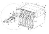
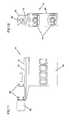
- FIG. 1is a rear perspective view of a telecommunications assembly with a plurality of fiber optic splitter modules installed within a chassis, with one of the adapter assemblies exploded out of the telecommunications assembly;
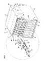
- FIG. 2is a top view of the telecommunications assembly of FIG. 1 ;
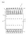
- FIG. 3is a front view of the telecommunications assembly of FIG. 1 ;
- FIG. 4is a rear view of the telecommunications assembly of FIG. 1 ;
- FIG. 5is a left side view of the telecommunications assembly of FIG. 1 ;
- FIG. 6is a right side view of the telecommunications assembly of FIG. 1 ;
- FIG. 6Aillustrates a front perspective of the chassis of the telecommunications assembly of FIG. 1 , shown with one fiber optic splitter module mounted therein;
- FIG. 7is a close-up view of the telecommunications assembly of FIG. 1 showing the adapter assembly exploded out of the telecommunications assembly;
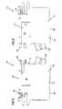
- FIG. 8is a front perspective view of one of the adapter assemblies of FIG. 1 ;
- FIG. 9is a rear perspective view of the adapter assembly of FIG. 8 ;
- FIG. 10is a right side view of the adapter assembly of FIG. 8 ;
- FIG. 11is a left side view of the adapter assembly of FIG. 8 ;
- FIG. 12is a front view of the adapter assembly of FIG. 8 ;
- FIG. 13is a rear view of the adapter assembly of FIG. 8 ;
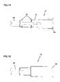
- FIG. 14is a top view of the adapter assembly of FIG. 8 ;
- FIG. 15is a bottom view of the adapter assembly of FIG. 8 ;
- FIG. 16is a right side view of one of the fiber optic splitter modules of FIG. 1 , shown with an adapter assembly mounted thereon;
- FIG. 17is a left side view of the fiber optic splitter module and adapter assembly of FIG. 16 ;
- FIG. 18is a front view of the fiber optic splitter module and adapter assembly of FIG. 16 ;
- FIG. 19is a rear view of the fiber optic splitter module and adapter assembly of FIG. 16 ;
- FIG. 20is a front perspective view of the fiber optic splitter module of FIG. 16 , shown in isolation without an adapter assembly mounted thereon;
- FIG. 21is a rear perspective view of the fiber optic splitter module of FIG. 20 ;
- FIG. 22is an exploded view of the fiber optic splitter module of FIG. 16 , shown with the adapter assembly exploded from the fiber optic splitter module;
- FIG. 23is a left side view of the fiber optic splitter module of FIG. 20 ;
- FIG. 24is a right side view of the fiber optic splitter module of FIG. 20 ;
- FIG. 25is a front view of the fiber optic splitter module of FIG. 20 ;
- FIG. 26is a rear view of the fiber optic splitter module of FIG. 20 ;
- FIG. 27is a top view of the fiber optic splitter module of FIG. 20 ;
- FIG. 28is a bottom view of the fiber optic splitter module of FIG. 20 ;
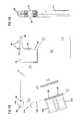
- FIG. 29is a right side view of the fiber optic splitter module of FIG. 20 , shown without a cover exposing the interior features of the fiber optic splitter module including routing of a fiber optic cable within the fiber optic splitter module;
- FIG. 30is a cross-sectional view taken along section line 30 - 30 of FIG. 29 ;
- FIG. 31illustrates a fiber optic splitter module partially inserted within the chassis of FIG. 1 , the chassis including an adapter assembly mounted thereon, the fiber optic splitter module shown in a position prior to the connectors of the splitter module having contacted a shield located within the chassis;
- FIG. 32illustrates the fiber optic splitter module of FIG. 31 , shown in a position within the chassis with the connectors of the fiber optic splitter module making initial contact with the shield located within the chassis;
- FIG. 33illustrates the fiber optic splitter module of FIG. 31 , shown in a fully inserted position within the chassis;
- FIG. 34is a side cross-sectional view of the fiber optic splitter module of FIG. 32 within the chassis, taken through the center of the fiber optic splitter module;
- FIG. 35is a side cross-sectional view of the fiber optic splitter module of FIG. 33 within the chassis, taken through the center of the fiber optic splitter module;
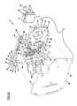
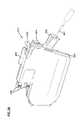
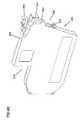
- FIG. 36illustrates a front perspective view of a fiber optic wavelength-division multiplexing (WDM) module having features that are examples of inventive aspects in accordance with the present disclosure, the WDM module configured to be inserted within the chassis that is shown in FIGS. 1-6 ;
- WDMwavelength-division multiplexing
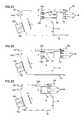
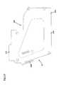
- FIG. 37is a rear perspective view of the WDM module of FIG. 36 ;
- FIG. 38is an exploded view of the WDM module of FIG. 36 ;
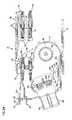
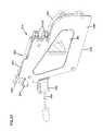
- FIG. 39is a right side view of the WDM module of FIG. 36 , shown without a cover exposing the interior features of the module including routing of fiber optic cables within the module;
- FIG. 40is a front perspective view of the main housing portion of the WDM module of FIG. 36 , the main housing portion shown without the internal components mounted therein;
- FIG. 41is a rear perspective view of the main housing portion of FIG. 40 ;
- FIG. 42is a right side view of the main housing portion of FIG. 40 ;
- FIG. 43is a left side view of the main housing portion of FIG. 40 ;
- FIG. 44is a front view of the main housing portion of FIG. 40 ;
- FIG. 45is a cross-sectional view of the main housing portion of FIG. 40 taken along line 45 - 45 of FIG. 43 ;
- FIG. 46is a rear perspective view of the cover of the WDM module of FIG. 36 ;
- FIG. 47is a right side view of the cover of FIG. 46 ;
- FIG. 48is a left side view of the cover of FIG. 46 .
- FIGS. 1-7illustrate a telecommunications assembly 10 that includes a telecommunications chassis 12 and a plurality of fiber optic splitter modules 14 adapted to be mounted within chassis 12 .
- Fiber optic splitter modules 14are configured to be slidably inserted within chassis 12 and be optically coupled to adapter assemblies 16 mounted within chassis 12 .
- Adapter assemblies 16 mounted within chassis 12form connection locations between connectors terminated to an incoming fiber optic cable and connectors of splitter modules 14 as will be discussed in further detail below.
- chassis 12includes a top wall 18 and a bottom wall 20 extending between a pair of opposing transverse sidewalls, 22 , 24 .
- Chassis 12includes an opening 26 through a rear side 28 of chassis 12 and an opening 30 through a front side 32 of chassis 12 .
- Fiber optic splitter modules 14are inserted into chassis 12 through front opening 30 .
- Adapter assemblies 16are inserted through and mounted adjacent rear opening 26 of chassis 12 .
- Sidewalls 22 , 24each include a cut-out 34 extending from front opening 30 toward rear side 28 .
- Splitter modules 14 mounted within chassis 12are visible through cut-out 34 .
- Sidewalls 22 , 24 of chassis 12also define an inset portion 36 at rear side 28 of chassis 12 to facilitate access to adapter assemblies 16 .
- chassis 12is shown with eight fiber optic splitter modules 14 mounted thereon. It should be noted that in other embodiments, the chassis may be sized to hold a larger or a smaller number of splitter modules. As will be described further below, it should be noted that the chassis may hold modules other than splitter modules, such as modules housing fiber optic multiplexers. A fiber optic splitter is only one example of telecommunications equipment that might be supported by the module.
- chassis 12includes a plurality of mounting locations 38 for slidably receiving splitter modules 14 .
- Each mounting location 38defines a slot 40 adjacent top wall 18 and a slot 42 adjacent bottom wall 20 of chassis 12 . Slots 42 adjacent bottom wall 20 are visible in FIG. 1 . Slots 40 adjacent top wall 18 are illustrated in FIG. 6A . Slots 40 , 42 extend from front 32 of chassis 12 to rear 28 of chassis 12 . Slots 40 , 42 are configured to receive mounting flanges 44 , 46 of splitter modules 14 as shown in FIG. 6A to align modules 14 with other components within chassis 12 (e.g., adapters of the adapter assemblies) to mate with pre-connectorized and/or pre-installed transmission cables.
- chassis 12includes a plurality of mounting locations 38 for slidably receiving splitter modules 14 .
- Each mounting location 38defines a slot 40 adjacent top wall 18 and a slot 42 adjacent bottom wall 20 of chassis 12 . Slots 42 adjacent bottom wall 20 are visible in FIG. 1 . Slots 40 adjacent top wall
- slots 40 defined underneath top wall 18 of chassis 12are deeper than slots 42 defined at bottom wall 20 of chassis 12 .
- the depth of slots 40 , 42are configured to accommodate the different sized flanges 44 , 46 that are defined at top and bottom walls of splitter modules 14 .
- slots 40 , 42 and mounting flanges 44 , 46 of fiber optic splitter modules 14provide a keying system to ensure that modules 14 are inserted into chassis 12 in the correct orientation.
- each bulkhead 48defines a downwardly extending front lip 50 ( FIG. 35 ) which interlocks with a resiliently deformable latch 52 (e.g., cantilever arm) of splitter module 14 to hold splitter module 14 in place within chassis 12 , as will be discussed in further detail below.
- a resiliently deformable latch 52e.g., cantilever arm
- each bulkhead 48defines a rear face 54 with a fastener hole 56 for receiving a fastener 58 (e.g., a thumbscrew) of an adapter assembly 16 for mounting adapter assembly 16 to chassis 12 .
- fastener hole 56is threaded to receive a screw-type fastener. It should be noted that in other embodiments, other types of fastening structures may be used to mount adapter assembly 16 to rear 28 of chassis 12 .
- each bulkhead 48Adjacent rear end 28 , each bulkhead 48 also includes a horizontal slot 60 and a vertical slot 62 that complement the shape of adapter assembly 16 to slidably receive adapter assembly 16 .
- FIGS. 8-15illustrate adapter assembly 16 according to the invention.
- Adapter assemblies 16form connection locations between the connectors terminated to an incoming fiber optic cable and the connectors of splitter modules 14 mounted within chassis 12 .
- adapter assembly 16includes two integrated adapters 64 formed as a part of a unitary housing 66 . In other embodiments, other number of adapters are also possible.
- Each adapter 64 of adapter assembly 16includes a front end 68 and a rear end 70 . Front end 68 of each adapter 64 receives a connector of fiber optic splitter module 14 and rear end 70 receives a connector terminated to an incoming fiber optic cable.
- Adapter assembly housing 66includes a chassis-mounting slide 72 extending from a top 74 of housing 66 , which is received within chassis 12 through rear end 28 .
- Slide 72defines a horizontal portion 76 and a vertical portion 78 .
- Horizontal portion 76is configured to be slidably received within horizontal slot 60 of bulkhead 48 and vertical portion 78 is configured to be slidably received within vertical slot 62 of bulkhead 48 .
- Chassis-mounting slide 72includes a pair of flanges 80 for supporting a fastener 58 for securing adapter assembly 16 to chassis 12 .
- fastener 58is positioned within an opening 56 defined by rear face 54 of bulkheads 48 located underneath top wall 18 of chassis 12 .
- Fastener 58is preferably a captive fastener.
- fastener 58is a thumbscrew. In other embodiments, other types of fasteners may be used.
- Fastener 58is rotated to threadingly couple the adapter assembly 16 to the bulkheads 48 .
- Fastener 58is also configured such that it is able to provide adapter assembly 16 with a predetermined amount of horizontal float relative to the chassis 12 once mounted thereon.
- the fastener 58 of the adapter assembly 16includes a flange 81 .
- the fastener 58is able to move horizontally within the flanges 80 relative to the adapter assembly housing 66 .
- the adapter assembly housing 66is able to float or move horizontally with respect to the fastener 58 between flange 81 and the rear face of the bulkhead 48 .
- adapter assembly 16is shown to be able to move or float a distance of A toward the rear end of chassis 12 .
- adapter assembly 16is able to horizontally float a distance A towards splitter module 14 as the engaged connector 118 of splitter module 14 pulls on adapter 64 of adapter assembly 16 .
- adapter assembly 16is provided with a certain amount of horizontal float when being engaged to and disengaged from splitter module 14 .
- each adapter 64is positioned through a side opening into adapter recesses formed within the adapter assembly housing 66 .
- the elements for each adapter 64include a ferrule alignment sleeve and a pair of inner housing halves. These elements are placed within recesses in manner similar to that shown in commonly-owned U.S. Pat. No. 5,317,663, issued May 20, 1993, entitled ONE-PIECE SC ADAPTER, the disclosure of which is incorporated herein by reference.
- a panelcloses opening and secures the elements within each adapter 64 .
- Adapters 64 shownare for SC style connectors, although other types, styles and formats of adapters may be used within the scope of the present disclosure and connectors to mate with these alternative adapters.
- a grip extension 218may be used with connectors 118 coupled to rear 70 of adapters 64 of adapter assembly 16 .
- Grip extension 218is designed to add length to the outer housing 150 of a connector 118 to facilitate access to individual connectors 118 in dense environments such as the telecommunications assembly 10 .
- Grip extensionis preferably first mounted over a cable before the cable is terminated to a connector 118 . Once the connector 118 is terminated to the cable, grip extension 218 is slid over the boot portion 220 of the connector and mounted to the outer housing 150 of connector 118 as shown in FIG. 7 .
- adapter assembly 16is shown mounted to a fiber optic splitter module 14 , outside of chassis 12 .
- FIGS. 20-30illustrate one of the fiber optic splitter modules 14 according to the invention.
- the fiber optic splitter module 14includes a splitter module housing 92 .
- Splitter module housing 92includes a main housing portion 94 and a removable cover 96 .
- Main housing portion 94includes a first transverse sidewall 98 extending between a top wall 100 , a bottom wall 102 , a rear wall 104 , and a front wall 106 .
- Removable cover 96defines a second transverse wall 108 of splitter module housing 92 and closes off the open side of module main housing 94 .
- Cover 96is mounted to main housing portion 94 by fasteners (not shown) through fastener mounts 110 defined on main housing portion 94 .
- Cover 96extends beyond first transverse sidewall 98 to form a top mounting flange 44 and a bottom mounting flange 46 of splitter module 14 .
- bottom flange 46 of splitter module housing 92 and the corresponding slot 42 on chassis 12are smaller in size than top flange 44 and the corresponding top slot 40 on chassis 12 .
- Bottom slot 42is sized so that, while bottom flange 46 may be received within slot 42 , the larger top flange 44 will not fit. This ensures that modules 14 are positioned within front opening 30 in a particular desired orientation.
- Rear wall 104 of main housing portion 94includes a curved portion 112 configured to provide bend radius protection to cables within interior 114 .
- Rear wall 104 of main housing 92also includes an inset portion 116 .
- a pair of fiber optic connectors 118 positioned at inset portion 116protrude rearwardly from rear wall 104 for mating with fiber optic adapters 64 of adapter assemblies 16 mounted within chassis 12 .
- front wall 106 of module main housing 94is angled with regard to front opening 30 of chassis 12 , which may aid in the direction of cables exiting module 14 toward a desired location.
- front walls 106could be made generally parallel to front 32 of chassis 12 within the scope of the present disclosure.
- Each module 14includes two cable exits 120 extending from front wall 106 of module main housing 94 .
- cable exits 120are slidably mounted to main housing 94 of module 14 and captured by cover 96 of module 14 when cover 96 is mounted to main housing 94 .
- Cable exits 120define a protruding rear lip 122 that is slidably inserted into slots 124 defined around front apertures 126 for accommodating cable exits 120 .
- Cover 96also includes slits 128 that receive rear lips 122 of the cable exits 120 to capture cable exits 120 .
- Cable exits 120permit telecommunications cables within module 14 to be directed outside of module 14 .
- Cable exits 120are preferably sized thin enough to fit within the profile of the fiber optic splitter module 14 , as shown in FIG. 25 , to preserve the density of the telecommunications assembly 10 .
- Main housing 94includes an integrally formed flexible latch 52 (i.e., cantilever arm) that is adapted to engage a portion of chassis 12 to hold module 14 within front opening 30 of chassis 12 .
- Flexible latch 52also deflects to permit withdrawal of module 14 from chassis 12 .
- latch 52 of module 14includes a finger grip tab 130 , a front latching tab 132 and a rear latching tab 134 .
- Front latching tab 132 and rear latching tab 134define a recess 136 thereinbetween.
- Rear latching tab 134includes a ramped face 138 that causes latch 52 to elastically deflect down when module 14 is being inserted into chassis 12 .
- Rear latching tab 134also includes a square face 140 that opposes a square face 142 of front latching tab 132 .
- Front lip 50 of bulkhead 48 at mounting location 38 of chassis 12is captured in recess 136 between the two latching tabs 132 , 134 to hold module 14 in place within chassis 12 .
- latch 52flexes back upwardly. Recess 136 between the two tabs 132 , 134 of latch 52 allows for a certain amount of horizontal float for splitter module 14 within chassis 12 , as will be discussed in further detail below.
- Module 14includes a fixed grip tab 144 opposing and adjacent to flexible latch 52 to aid removal of module 14 from chassis 12 .
- Fixed grip tab 144is formed as a part of front wall 106 of module 14 .
- Fixed grip tab 144is preferably positioned on module 14 opposite latch 52 so that a user may apply opposing force on latch 52 and fixed grip tab 144 to securely grasp module 14 and remove it from chassis 12 .
- Fixed grip tab 144is preferably positioned on module 14 close enough to latch 52 so that a user may be apply the force with two adjacent fingers of the hand.
- FIG. 22shows an exploded view of fiber optic splitter module 14 illustrating the internal components of module 14 .
- Fiber optic splitter module 14is shown in FIG. 22 with adapter assembly 16 exploded from module 14 .
- splitter module 14includes a first radius limiter 146 adjacent curved portion 122 of rear wall 104 of main housing 94 .
- Splitter module 14includes a second radius limiter 148 adjacent front wall 106 of housing 94 near cable exits 120 .
- Connectors 118 of splitter module 14are slidably inserted into opposing slots 154 formed in apertures 156 at the rear wall 104 .
- Connectors 118project out from rear wall 104 at inset portion 116 of rear wall 104 .
- Outer housings 150 of connectors 118include transverse flanges 152 that are received within the opposing slots 154 formed in apertures 156 that accommodate the connectors 118 . Once slidably inserted, connectors 118 are captured within housing 92 by cover 96 .
- an optical component 158such as a fiber optic splitter or a fan-out.
- Optical component 158is held against the interior of bottom wall 102 by a clamp 160 (i.e., bracket).
- Clamp 160is mounted to a clamp mount 162 defined on splitter module main housing 94 with fasteners (not shown).
- clamp mount 162includes two pairs of mounting holes 164 , 166 . Either the upper set of holes 164 or the lower set of holes 166 are utilized depending upon the size of the clamp that will be used to hold optical component 158 against bottom wall 102 .
- different optical componentsmay have different thicknesses and may require the use of different sized clamps for holding the optical components in place.
- two optical components that are stacked on top of anothermay be used, in which case, a smaller clamp would be used to hold the two optical components in place.
- Optical component 158is offset from the interior side of first transverse sidewall 98 by a set of cable management structures 168 .
- the set of cable management structures 168are elongate structures 170 defining cable management slits 172 therein between.
- cablescan be routed through slits 172 between optical component 158 and the interior of first transverse wall 98 (please see FIGS. 29 and 30 ).
- Splitter module main housing 94also includes integrally formed crimp holders 174 (e.g., slots) adjacent front wall 106 of housing 94 underneath second radius limiter 148 .
- Crimp elements 176crimped to the ends of cables that are split by optical component 158 are slidably received into crimp holders 174 as shown in FIGS. 22 and 29 .
- Crimp elements 176define square flanges 175 between which is defined a recessed portion 177 .
- the crimp holders 174include complementary structure to the crimp elements such that once the crimp elements 176 are slidably inserted into the crimp holders 174 , the crimp elements 176 are prevented from moving in a longitudinal direction due to the flanges 175 .
- crimp elements 176are held in place by cover 96 that is mounted to splitter module main housing 94 .
- cover 96In the embodiment shown, there are nine crimp holding slots 174 , each one being able to accommodate up to four crimp elements 176 .
- Other numbersare possible.
- Other complementary shapes between the crimp elements and the crimp holding slotsare also possible to provide a slidable fit and to prevent axial movement of the crimp elements once inserted therein the crimp holders.
- FIG. 29shows fiber optic splitter module 14 without a cover 96 exposing the interior features of fiber optic splitter module 14 including routing of a fiber optic cable within fiber optic splitter module 14 .
- FIG. 30illustrates a cross-sectional view taken along section line 30 - 30 of FIG. 29 .
- a first cable 178extends from connector 118 toward optical component 158 , mounted within module housing 92 .
- Optical component 158may be a splitter or a fan-out or another type of optical component.
- optical component 158is a fiber optic splitter that splits the signal of a single strand to a plurality of secondary signals.
- first cable 178may be a multi-strand fiber cable with a plurality of strands of optical fiber and optical component may be a fanout to separate the individual strands into each of a plurality of second cables.
- First cable 178as it extends toward optical component 158 , is inserted through slits 172 (see FIGS. 22 , 29 , and 30 ) located between optical component 158 and the inner side of first transverse sidewall 98 of module housing 94 and looped around first radius limiter 146 and then around second radius limiter 148 before being received by optical component 158 .
- Second cables 180extend from optical component 158 and are looped again all the way around first radius limiter 146 before heading toward crimp holders 174 . From crimp holders 174 , cables (not shown) crimped to the other ends of the crimps 176 exit the module through module exits 120 .
- An outside cablemay extend to rear end 70 of an adapter 64 of adapter assembly 16 and be terminated by a connector (not shown in FIG. 29 ) that is optically connected to connector 118 of module 14 through adapter 64 once module 14 is inserted within chassis 12 .
- a connectornot shown in FIG. 29
- the embodiment of the fiber optic splitter module 14 shown in the figuresis configured such that it can accommodate reduced bend radius fiber.
- a reduced bend-radius fibermay have a bend radius of about 15 mm whereas a non-reduced bend-radius fiber may have a bend radius of about 30 mm.
- FIGS. 31-35The insertion of a splitter module 14 into chassis 12 is illustrated in FIGS. 31-35 .
- insertion of fiber optic module 12 into front opening 30 of chassis 12begins the mating of module 14 to chassis 12 and to adapters 64 of adapter assembly 16 .
- Top flangesengage 44 top slots 40 and bottom flanges 46 engages bottom slots 42 of chassis 12 as module 14 is inserted.
- chassis 12includes a flexible shield 182 in each mounting location 38 .
- Shield 182is adapted to prevent protection against accidental exposure to light.
- Shield 182is positioned in front end 68 of each adapter 64 of adapter assembly 16 .
- shield 182will prevent accidental exposure to these signals which might damage eyes or other sensitive organs, or nearby communications equipment. The insertion of splitter module 14 pushes shield 182 out of the way as illustrated in FIGS. 31-33 .
- Shield 182is deflected by module 14 as module 14 is inserted through front opening 30 so that connectors 118 of module 14 can mate with adapters 64 of adapter assemblies 16 .
- Shield 182is preferably made of a resilient deformable material that will return to the position when module 14 is withdrawn from mounting location 38 .
- a fiber optic splitter module 14is shown partially inserted within chassis 12 prior to connectors 118 of splitter module 14 having contacted shield 182 of chassis 12 .
- fiber optic splitter module 14is shown in a position within chassis 12 with connectors 118 of fiber optic splitter module 14 making initial contact with shield 182 of chassis 12 to move shield 182 out of the way (a side cross-sectional view is shown in FIG. 34 ).
- fiber optic splitter module 14is shown in a fully inserted position within chassis 12 , having moved shield 182 out of the way (a side cross-sectional view is shown in FIG. 35 ).
- Shield 182is configured such that shield 182 does not engage the ferrule 184 of connector 118 of splitter module 14 when connector 118 contacts shield 182 to move it out of the way. Instead, outer connector housing 150 pushes shield 182 out of the way.
- Shield 182may be connected to chassis 12 by fasteners, or, alternatively, shield 182 may be formed integrally with chassis 12 or mounted by spot-welding or other fastening techniques.
- module 14As shield 182 is fully deflected, further insertion of module 14 brings connectors 118 into contact with adapters 64 and connectors 118 are received within front ends 68 of adapters 64 . Latch 52 is deflected inwardly as module 14 is inserted and then flexes back so that front lip 50 of bulkhead 48 is captured in recess 136 . Module 14 is now in position to process and transmit signals from cable through first cable 178 , optical component 158 and second cable 180 within module interior 114 .
- recess 136 between the two tabs 132 , 134 of latch 52provides a certain amount of horizontal float for the splitter module 14 within chassis 12 .
- Front lip 50 of bulkhead 48is allowed to move a distance of D as indicated in FIG. 35 before it makes contact with square face 140 of rear tab 134 .
- Splitter module 14is configured such that, when splitter module 14 is pulled away from front 32 of chassis 12 , distance D front lip 50 of bulkhead 48 travels before contacting square face 140 of rear tab 134 is less than the horizontal float (i.e., distance A) provided for adapter assembly 16 , as discussed before.
- splitter module 14provides a form of protection from accidentally disengaging connectors 118 of the module from adapter assemblies 16 at rear 28 of chassis 12 .
- the size of recess 136 of module 14is configured such that the horizontal float of splitter module 14 is interrupted before the adapter assembly 16 can be pulled far enough toward the front of chassis 12 to stop its horizontal movement and accidentally disengage connectors 118 of module 14 from adapters 64 .
- FIGS. 36-39illustrate a fiber optic wavelength division multiplexing (WDM) module 214 having features that are examples of inventive aspects in accordance with the present disclosure.
- the WDM module 214is configured similarly to the splitter module 14 of FIGS. 20-30 in certain aspects.
- the WDM module 214is configured to be inserted within the chassis 12 in a similar manner as module 14 .
- the WDM module 214houses a fiber optic multiplexer/demultiplexer 358 and the features of the module 214 are configured for supporting the multiplexer/demultiplexer 358 and integrating into a telecommunications system.
- the WDM module 214includes internal features for housing the multiplexer/demultiplexer 358 and routing and managing cables to and from the multiplexer/demultiplexer 358 and external features for integrating the multiplexer/demultiplexer 358 into a telecommunications assembly including a chassis 12 , such as the telecommunications assembly 10 of FIGS. 1-7 .
- WDM module 214is shown in an exploded orientation.
- WDM module 214includes a module housing 292 that includes a main housing portion 294 and a removable cover 296 .
- the main housing portion 294is illustrated separately in FIGS. 40-45 and the cover 296 is illustrated separately in FIGS. 46-48 .
- the module housing 292is configured to house a multiplexer/demultiplexer chip 358 therewithin for multiplexing/demultiplexing signals that are input and output through connectors 318 of the module 214 .
- the module housing 292includes a cable exit 320 for relaying fiber signals to customers.
- the WDM module 214includes a number of cable management/routing features as will be described in further detail below.
- One of the cable management featuresincludes the fiber retainer 360 that is removably mounted to the main housing portion 294 of the module housing 292 , as shown in FIG. 38 .
- a label 361 including indicia relating to the module 214may be mounted to the cover portion 296 of the housing 292 .
- the main housing portion 294defines a first sidewall 298 extending between a top wall 300 , a bottom wall 302 , a rear wall 304 , and a front wall 306 .
- Removable cover 296defines a second sidewall 308 of the module housing 292 and closes off the open side of module main housing portion 294 .
- Cover 296is mounted to main housing portion 294 by fasteners through fastener holes 309 in the cover 296 and fastener mounts 310 defined on main housing portion 294 .
- Cover 296extends beyond the first sidewall 298 to form a top mounting flange 244 and a bottom mounting flange 246 of the WDM module 214 , similar to the splitter module 14 (see FIGS. 36 and 37 ).
- the bottom flange 246 and the corresponding slot 42 on chassis 12are smaller in size than top flange 244 and the corresponding top slot 40 on chassis 12 .
- Bottom slot 42is sized so that, while bottom flange 246 may be received within slot 42 , the larger top flange 244 will not fit. This ensures that the WDM modules 214 are positioned within front opening 30 of the chassis 12 in a particular desired orientation to be correctly coupled to adapter assemblies 16 mounted adjacent rear 28 of chassis 12 at each mounting location 38 .
- Rear wall 304 of main housing portion 294includes a curved portion 312 configured to provide bend radius protection to cables within interior of the module 214 . Similar to module 14 , the rear wall 304 of main housing 294 includes an inset portion 316 and a pair of fiber optic connectors 318 positioned at the inset portion 316 . The connectors 318 protrude rearwardly from rear wall 304 for mating with fiber optic adapters 64 of adapter assemblies 16 mounted within chassis 12 .
- front wall 306 of the module main housing 294is angled with regard to front opening 30 of chassis 12 , which may aid in the direction of cables exiting the WDM module 214 toward a desired location.
- front wallscould be made generally parallel to front 32 of chassis 12 within the scope of the present disclosure.
- the embodiment of the WDM module 214 illustratedincludes one cable exit 320 extending from front wall 306 of module main housing 294 .
- the cable exit 320is slidably mounted to main housing 294 of the WDM module 214 and is captured by the cover 296 when cover 296 is mounted to main housing 294 .
- the cable exit 320defines a protruding rear lip 322 that is slidably inserted into a slot 324 defined around a front aperture 326 for accommodating the cable exit 320 .
- Cover 296also includes a slit 328 that receives the rear lip 322 of the cable exit 320 to capture the cable exit 320 .
- the cable exit 320permits telecommunications cables within module 214 that have been multiplexed/demultiplexed to be directed outside of module 214 .
- the cable exit 320is preferably sized thin enough to fit within the profile of the WDM module 214 , similar to splitter module 14 , as shown in FIG. 25 , to preserve the density of the telecommunications assembly.
- the main housing 294includes an integrally formed flexible latch 252 (i.e., cantilever arm) that is adapted to engage a portion of chassis 12 to hold module within front opening 30 of chassis 12 .
- Flexible latch 252also deflects to permit withdrawal of module from chassis 12 .
- the flexible latch 252 of the module 214is constructed similarly to that of module 14 and operates in a similar manner for insertion and removal of the module from chassis 12 .
- the latch 252 of module 214includes a finger grip tab 330 , a front latching tab 332 and a rear latching tab 334 that cooperate with the bulkhead 48 at the mounting location 38 of the chassis 12 .
- the WDM module 214also includes a fixed grip tab 344 , similar to module 14 , opposing and adjacent to flexible latch 252 to aid removal of module 214 from chassis 12 .
- Fixed grip tab 344is preferably positioned on module 214 opposite latch 252 so that a user may apply opposing force on latch 252 and fixed grip tab 344 to securely grasp module 214 and remove it from chassis 12 with two adjacent fingers of the hand.
- the insertion of the WDM module 214 into chassis 12is similar to that of module 14 and is described above with respect to FIGS. 31-35 .
- module 214within interior of main housing 294 , module 214 includes a first radius limiter 346 adjacent curved portion 322 of rear wall 304 of main housing 294 .
- the WDM module 214includes a second radius limiter 348 adjacent front wall 306 of housing near the cable exit 320 .
- a third radius limiter 349is located adjacent the front wall 306 below the second radius limiter 348 .
- the radius limiters 346 , 348 , 349provide bend-protection to fiber cables within the module 214 while providing cable management/routing functionality.
- Adjacent bottom wall 302 of main housing 294 within interiorare located a first guide 364 and a second guide 366 for placement of the multiplexer chip 358 within the module 214 .
- a third guide 368is located adjacent the first radius limiter 346 .
- the first radius limiter 346defines a curved wall 415 .
- the curved wall 415includes a first end 417 and a second end 419 .
- the first and second ends 417 , 419 of the curved wall 415also act as guides in positioning the multiplexer chip 358 within the main housing 294 .
- the first, second, and third guides 364 , 366 , 368 and the ends 417 , 419 of the curved wall 415 of the first radius limiter 346form a frame structure around the chip 358 for correctly positioning the multiplexer chip 358 within the interior of the main housing portion 294 . As shown in FIGS. 38 and 39 , once the multiplexer chip 358 is placed within the guides, the chip 358 is held within the module 214 against the first sidewall 298 by the removable cover 296 .
- the first sidewall 298 of the main housing 294includes a first notch 370 for accommodating fiber cables that may extend underneath the multiplexer chip 358 .
- the notch 370creates a space between the chip 358 and the first sidewall 298 and accommodates any cables routed between the chip 358 and the first sidewall 298 .
- the module main housing 294also includes integrally formed crimp holders 374 (e.g., slots) adjacent front wall 306 of housing 294 in between the second and third radius limiters 348 , 349 .
- Crimp elements 376(see FIGS. 38-39 ) crimped to the ends of cables that are multiplexed/demultiplexed by the chip 358 are slidably received into crimp holders 374 .
- Crimp elements 376define square flanges 375 between which is defined a recessed portion 377 .
- the crimp holders 374include complementary structure to the crimp elements 376 such that once the crimp elements 376 are slidably inserted into the crimp holders 374 , the crimp elements 376 are prevented from moving in a longitudinal direction due to the flanges 375 . Once slidably inserted, crimp elements 376 are held in place by the cover 296 that is mounted to module main housing 294 . In the embodiment shown, there are four crimp holding slots 374 , each one being able to accommodate up to four crimp elements 376 . Other numbers are possible. Other complementary shapes between the crimp elements and the crimp holding slots are also possible to provide a slidable fit and to prevent axial movement of the crimp elements once inserted into the crimp holders.
- connectors 318 of WDM module 214are slidably inserted into opposing slots 354 formed in apertures 356 at the rear wall 304 .
- Connectors 318project out from rear wall 304 at inset portion 316 of rear wall 304 .
- Connectors 318 of WDM module 214are similar in construction to connectors 118 of the splitter module 14 .
- Connectors 318 of the WDM module 214may function both as input connectors and output connectors since the WDM module 214 is configured to both demultiplex signals coming in and multiplex signals going out of the connectors 318 .
- the main housing 294includes a reinforcement structure 311 extending from the sidewall 298 of the main housing 294 .
- the reinforcement structure 311aligns and fits into a recess 491 defined on the sidewall 308 of the cover 296 (see FIGS. 46 and 48 ) when the main housing 294 and cover 296 are assembled together.
- FIGS. 46-48illustrate the cover 296 of the WDM module 214 .
- the cover 296is configured to be fastened to the module main housing portion 294 .
- the cover 296defines different sized flanges 244 , 246 for slidably inserting the module 214 within the chassis 12 and for correctly orienting the module 214 with respect to the chassis 12 .
- the cover 296defines a tab 373 adjacent the front end 371 thereof.
- the tab 373is slidably inserted within a recess 431 defined at the front wall 306 of the main housing portion 294 (see FIGS. 38 and 41 ) to correctly orient the cover 296 with respect to the main housing portion 294 .
- the cover 296also includes protruding portions 379 defined around the periphery and slots 381 defined between the protruding portions 379 that intermate with corresponding structures located around the periphery of the main housing 294 for correctly placing the cover 296 onto the main housing 294 .
- the cover 296defines a second notch 372 on the second sidewall 308 .
- the second notch 372is configured to accommodate the multiplexer chip 358 once the cover 296 is mounted on the main housing portion 294 .
- the cover 296also defines slots 383 on the second sidewall 308 for receiving the structures of the main housing portion 294 that define the crimp holders 374 thereinbetween.
- the slots 383are located in a notched area 385 .
- This third notch 385accommodates the area of the main housing portion 294 with the crimp holders 374 .
- the WDM module 214is shown in FIG. 39 with the cover 296 and the fiber retainer 360 removed from the main housing portion 294 to illustrate the internal components and to illustrate the cable routing.
- a first cable 378extends from one of the connectors 318 toward and around the second radius limiter 348 . From the second radius limiter 348 , the first cable 378 extends downwardly toward the third radius limiter 349 and around the first guide 364 toward the rear of the module 214 . As the cable 378 extends from the first guide 364 , the cable 378 is positioned in a space 400 defined between the bottom wall 302 and the multiplexer chip 358 . After going around the second guide 366 and upwardly, the first cable 378 goes around the first radius limiter 346 and toward the front of the module 214 .
- the first cable 378is, then, led around the second radius limiter 348 and the third radius limiter 349 . From the third radius limiter 349 , the first cable 378 enters the multiplexer chip 358 .
- the fiber optic signals that are input into the multiplexer 358are demultiplexed and split into the different wavelengths that are carried by separate second cables 380 for service to different customers.
- second cables 380extend from the chip 358 and are looped around the first radius limiter 346 and then extend underneath the chip 358 before they are looped again around the first radius limiter 346 .
- the first notch 370accommodates the cables 380 going underneath the chip 358 between the sidewall 298 of the main housing 294 and the chip 358 .
- the second cables 380After the second cables 380 have been looped around the first radius limiter 346 again, they extend toward crimp holders 374 . From crimp holders 374 , cables crimped to the other ends of the crimps exit the module through exit as customer output pigtails 401 .
- the routing of the fiber optic cables within module 214 as shown in FIG. 39is only one example and other ways of routing the cables within the module are possible.
- a fiber retainer 360may be placed on the main housing portion 294 to keep cables 380 wrapped around the first radius limiter 346 .
- the fiber retainer 360is planar and includes a semicircular shape to match the contour of the curved portion 312 of the rear wall 304 of the main housing 294 .
- the fiber retainer 360includes three tabs 403 positioned around the periphery. The three tabs 403 are placed within slots 405 formed around the curved portion 312 of the rear wall 304 .
- the fiber retainer 360includes a semicircular opening 407 which accommodates a portion of the first radius limiter 346 that protrudes through the opening 407 . When the fiber retainer 360 is placed on the main housing portion 294 , it lies flush with the main housing portion 294 and is held thereagainst by the cover 296 .
- the multiplexing chip 358provides a two-way signal path for the signal going through it.
- Input signals input through the connectors 318are demultiplexed and are split into different wavelengths and signals coming from the customers are multiplexed and combined into a single signal to be carried on a single fiber that is output also through the connectors 318 .
- an outside cable(not shown) terminated by a connector is optically connected to a connector 318 of the module 214 through an adapter 64 of the adapter assembly 16 . This connection is established by the slidable insertion of the WDM module 214 into the chassis 12 .
- the WDM module 214may house a 1 ⁇ 4 dense wavelength division multiplexing chip. According to another embodiment, the WDM module may house a 1 ⁇ 8 dense wavelength division multiplexing chip. According to another embodiment, the WDM module may house a 1 ⁇ 16 dense wavelength division multiplexing chip. In another embodiment, the module may house a coarse wavelength division multiplexing chip. Other types of multiplexer chips are also contemplated.
- an overlay filter chipmay be used within the module 214 .
- Such a chipmay be positioned in the space located between the bottom wall 302 of the main housing 294 of the module 214 and the multiplexer chip 358 .
Landscapes
- Physics & Mathematics (AREA)
- General Physics & Mathematics (AREA)
- Optics & Photonics (AREA)
- Light Guides In General And Applications Therefor (AREA)
- Mechanical Coupling Of Light Guides (AREA)
Abstract
Description
Claims (15)
Priority Applications (1)
| Application Number | Priority Date | Filing Date | Title |
|---|---|---|---|
| US13/049,176US8542972B2 (en) | 2007-10-22 | 2011-03-16 | Wavelength division multiplexing module |
Applications Claiming Priority (3)
| Application Number | Priority Date | Filing Date | Title |
|---|---|---|---|
| US11/975,905US7536075B2 (en) | 2007-10-22 | 2007-10-22 | Wavelength division multiplexing module |
| US12/467,564US7912336B2 (en) | 2007-10-22 | 2009-05-18 | Wavelength division multiplexing module |
| US13/049,176US8542972B2 (en) | 2007-10-22 | 2011-03-16 | Wavelength division multiplexing module |
Related Parent Applications (1)
| Application Number | Title | Priority Date | Filing Date |
|---|---|---|---|
| US12/467,564ContinuationUS7912336B2 (en) | 2007-10-22 | 2009-05-18 | Wavelength division multiplexing module |
Publications (2)
| Publication Number | Publication Date |
|---|---|
| US20110222830A1 US20110222830A1 (en) | 2011-09-15 |
| US8542972B2true US8542972B2 (en) | 2013-09-24 |
Family
ID=40563585
Family Applications (3)
| Application Number | Title | Priority Date | Filing Date |
|---|---|---|---|
| US11/975,905Expired - Fee RelatedUS7536075B2 (en) | 2007-10-22 | 2007-10-22 | Wavelength division multiplexing module |
| US12/467,564ActiveUS7912336B2 (en) | 2007-10-22 | 2009-05-18 | Wavelength division multiplexing module |
| US13/049,176Active2028-01-18US8542972B2 (en) | 2007-10-22 | 2011-03-16 | Wavelength division multiplexing module |
Family Applications Before (2)
| Application Number | Title | Priority Date | Filing Date |
|---|---|---|---|
| US11/975,905Expired - Fee RelatedUS7536075B2 (en) | 2007-10-22 | 2007-10-22 | Wavelength division multiplexing module |
| US12/467,564ActiveUS7912336B2 (en) | 2007-10-22 | 2009-05-18 | Wavelength division multiplexing module |
Country Status (1)
| Country | Link |
|---|---|
| US (3) | US7536075B2 (en) |
Cited By (8)
| Publication number | Priority date | Publication date | Assignee | Title |
|---|---|---|---|---|
| US20180156999A1 (en)* | 2012-05-16 | 2018-06-07 | Corning Optical Communications LLC | High-density port tap fiber optic modules, and related systems and methods for monitoring optical networks |
| US10031305B2 (en) | 2012-12-19 | 2018-07-24 | CommScope Connectivity Belgium BVBA | Distribution device with incrementally added splitters |
| US10444456B2 (en) | 2008-08-29 | 2019-10-15 | Corning Optical Communications LLC | High density and bandwidth fiber optic apparatuses and related equipment and methods |
| US10606014B2 (en) | 2008-08-29 | 2020-03-31 | Corning Optical Communications LLC | Independently translatable modules and fiber optic equipment trays in fiber optic equipment |
| US10606009B2 (en) | 2015-12-01 | 2020-03-31 | CommScope Connectivity Belgium BVBA | Cable distribution system with fan out devices |
| US10637220B2 (en) | 2016-01-28 | 2020-04-28 | CommScope Connectivity Belgium BVBA | Modular hybrid closure |
| US10732370B2 (en) | 2014-06-17 | 2020-08-04 | CommScope Connectivity Belgium BVBA | Cable distribution system |
| US11294135B2 (en) | 2008-08-29 | 2022-04-05 | Corning Optical Communications LLC | High density and bandwidth fiber optic apparatuses and related equipment and methods |
Families Citing this family (75)
| Publication number | Priority date | Publication date | Assignee | Title |
|---|---|---|---|---|
| US6885798B2 (en) | 2003-09-08 | 2005-04-26 | Adc Telecommunications, Inc. | Fiber optic cable and furcation module |
| US7418181B2 (en) | 2006-02-13 | 2008-08-26 | Adc Telecommunications, Inc. | Fiber optic splitter module |
| US8798427B2 (en) | 2007-09-05 | 2014-08-05 | Corning Cable Systems Llc | Fiber optic terminal assembly |
| US7885505B2 (en) | 2007-10-22 | 2011-02-08 | Adc Telecommunications, Inc. | Wavelength division multiplexing module |
| US7536075B2 (en)* | 2007-10-22 | 2009-05-19 | Adc Telecommunications, Inc. | Wavelength division multiplexing module |
| US8107816B2 (en) | 2008-01-29 | 2012-01-31 | Adc Telecommunications, Inc. | Wavelength division multiplexing module |
| US8270796B2 (en)* | 2008-03-04 | 2012-09-18 | Adc Telecommunications, Inc. | Multi-port adapter block |
| US7856166B2 (en) | 2008-09-02 | 2010-12-21 | Corning Cable Systems Llc | High-density patch-panel assemblies for optical fiber telecommunications |
| CN102209921B (en) | 2008-10-09 | 2015-11-25 | 康宁光缆系统有限公司 | There is the fibre-optic terminus supported from the adapter panel of the input and output optical fiber of optical splitters |
| US8879882B2 (en) | 2008-10-27 | 2014-11-04 | Corning Cable Systems Llc | Variably configurable and modular local convergence point |
| US20100129030A1 (en)* | 2008-11-24 | 2010-05-27 | Giraud William J | Universal Optical Splitter Modules and Related Mounting Brackets, Assemblies and Methods |
| EP2221932B1 (en) | 2009-02-24 | 2011-11-16 | CCS Technology Inc. | Holding device for a cable or an assembly for use with a cable |
| US8699838B2 (en) | 2009-05-14 | 2014-04-15 | Ccs Technology, Inc. | Fiber optic furcation module |
| US8538226B2 (en) | 2009-05-21 | 2013-09-17 | Corning Cable Systems Llc | Fiber optic equipment guides and rails configured with stopping position(s), and related equipment and methods |
| US9075216B2 (en) | 2009-05-21 | 2015-07-07 | Corning Cable Systems Llc | Fiber optic housings configured to accommodate fiber optic modules/cassettes and fiber optic panels, and related components and methods |
| US20100303431A1 (en)* | 2009-05-29 | 2010-12-02 | Cox Terry D | Fiber Optic Harnesses and Assemblies Facilitating Use of a Pre-Connectorized Fiber Optic Cable(s) with a Fiber Optic Terminal |
| US8712206B2 (en) | 2009-06-19 | 2014-04-29 | Corning Cable Systems Llc | High-density fiber optic modules and module housings and related equipment |
| WO2010148325A1 (en) | 2009-06-19 | 2010-12-23 | Corning Cable Systems Llc | High fiber optic cable packing density apparatus |
| US8625950B2 (en) | 2009-12-18 | 2014-01-07 | Corning Cable Systems Llc | Rotary locking apparatus for fiber optic equipment trays and related methods |
| US8992099B2 (en) | 2010-02-04 | 2015-03-31 | Corning Cable Systems Llc | Optical interface cards, assemblies, and related methods, suited for installation and use in antenna system equipment |
| US9547144B2 (en) | 2010-03-16 | 2017-01-17 | Corning Optical Communications LLC | Fiber optic distribution network for multiple dwelling units |
| US8913866B2 (en) | 2010-03-26 | 2014-12-16 | Corning Cable Systems Llc | Movable adapter panel |
| CA2796221C (en) | 2010-04-16 | 2018-02-13 | Ccs Technology, Inc. | Sealing and strain relief device for data cables |
| US8792767B2 (en) | 2010-04-16 | 2014-07-29 | Ccs Technology, Inc. | Distribution device |
| EP2381284B1 (en) | 2010-04-23 | 2014-12-31 | CCS Technology Inc. | Under floor fiber optic distribution device |
| US9239442B2 (en) | 2010-04-27 | 2016-01-19 | Adc Communications (Shanghai) Co., Ltd. | Fiber optic module and chassis |
| US9632270B2 (en) | 2010-04-30 | 2017-04-25 | Corning Optical Communications LLC | Fiber optic housings configured for tool-less assembly, and related components and methods |
| US9075217B2 (en) | 2010-04-30 | 2015-07-07 | Corning Cable Systems Llc | Apparatuses and related components and methods for expanding capacity of fiber optic housings |
| US9519118B2 (en) | 2010-04-30 | 2016-12-13 | Corning Optical Communications LLC | Removable fiber management sections for fiber optic housings, and related components and methods |
| US8660397B2 (en) | 2010-04-30 | 2014-02-25 | Corning Cable Systems Llc | Multi-layer module |
| US9720195B2 (en) | 2010-04-30 | 2017-08-01 | Corning Optical Communications LLC | Apparatuses and related components and methods for attachment and release of fiber optic housings to and from an equipment rack |
| US8705926B2 (en) | 2010-04-30 | 2014-04-22 | Corning Optical Communications LLC | Fiber optic housings having a removable top, and related components and methods |
| US8879881B2 (en) | 2010-04-30 | 2014-11-04 | Corning Cable Systems Llc | Rotatable routing guide and assembly |
| US8718436B2 (en) | 2010-08-30 | 2014-05-06 | Corning Cable Systems Llc | Methods, apparatuses for providing secure fiber optic connections |
| WO2012054454A2 (en) | 2010-10-19 | 2012-04-26 | Corning Cable Systems Llc | Transition box for multiple dwelling unit fiber optic distribution network |
| US9279951B2 (en)* | 2010-10-27 | 2016-03-08 | Corning Cable Systems Llc | Fiber optic module for limited space applications having a partially sealed module sub-assembly |
| US8662760B2 (en) | 2010-10-29 | 2014-03-04 | Corning Cable Systems Llc | Fiber optic connector employing optical fiber guide member |
| US9116324B2 (en) | 2010-10-29 | 2015-08-25 | Corning Cable Systems Llc | Stacked fiber optic modules and fiber optic equipment configured to support stacked fiber optic modules |
| CA2819235C (en) | 2010-11-30 | 2018-01-16 | Corning Cable Systems Llc | Fiber device holder and strain relief device |
| WO2012106510A2 (en) | 2011-02-02 | 2012-08-09 | Corning Cable Systems Llc | Dense fiber optic connector assemblies and related connectors and cables suitable for establishing optical connections for optical backplanes in equipment racks |
| US9182563B2 (en) | 2011-03-31 | 2015-11-10 | Adc Telecommunications, Inc. | Adapter plate for fiber optic module |
| US9008485B2 (en) | 2011-05-09 | 2015-04-14 | Corning Cable Systems Llc | Attachment mechanisms employed to attach a rear housing section to a fiber optic housing, and related assemblies and methods |
| AU2012275598A1 (en) | 2011-06-30 | 2014-01-16 | Corning Optical Communications LLC | Fiber optic equipment assemblies employing non-U-width-sized housings and related methods |
| US8953924B2 (en) | 2011-09-02 | 2015-02-10 | Corning Cable Systems Llc | Removable strain relief brackets for securing fiber optic cables and/or optical fibers to fiber optic equipment, and related assemblies and methods |
| WO2013033890A1 (en) | 2011-09-06 | 2013-03-14 | Adc Telecommunications, Inc. | Adapter for fiber optic module |
| US9038832B2 (en) | 2011-11-30 | 2015-05-26 | Corning Cable Systems Llc | Adapter panel support assembly |
| US9219546B2 (en) | 2011-12-12 | 2015-12-22 | Corning Optical Communications LLC | Extremely high frequency (EHF) distributed antenna systems, and related components and methods |
| US10110307B2 (en) | 2012-03-02 | 2018-10-23 | Corning Optical Communications LLC | Optical network units (ONUs) for high bandwidth connectivity, and related components and methods |
| US9004778B2 (en) | 2012-06-29 | 2015-04-14 | Corning Cable Systems Llc | Indexable optical fiber connectors and optical fiber connector arrays |
| US9250409B2 (en) | 2012-07-02 | 2016-02-02 | Corning Cable Systems Llc | Fiber-optic-module trays and drawers for fiber-optic equipment |
| US9049500B2 (en) | 2012-08-31 | 2015-06-02 | Corning Cable Systems Llc | Fiber optic terminals, systems, and methods for network service management |
| US9042702B2 (en) | 2012-09-18 | 2015-05-26 | Corning Cable Systems Llc | Platforms and systems for fiber optic cable attachment |
| US8909019B2 (en) | 2012-10-11 | 2014-12-09 | Ccs Technology, Inc. | System comprising a plurality of distribution devices and distribution device |
| ES2551077T3 (en) | 2012-10-26 | 2015-11-16 | Ccs Technology, Inc. | Fiber optic management unit and fiber optic distribution device |
| US8985862B2 (en) | 2013-02-28 | 2015-03-24 | Corning Cable Systems Llc | High-density multi-fiber adapter housings |
| US9274300B2 (en)* | 2013-04-22 | 2016-03-01 | M2 Optics, Inc. | High density enclosure for optical modules |
| WO2015126472A2 (en) | 2013-11-11 | 2015-08-27 | Adc Telecommunications, Inc. | Telecommunications module |
| WO2015200321A1 (en) | 2014-06-23 | 2015-12-30 | Adc Telecommunications, Inc. | Fiber cable fan-out assembly and method |
| US10054753B2 (en) | 2014-10-27 | 2018-08-21 | Commscope Technologies Llc | Fiber optic cable with flexible conduit |
| AU2015207954C1 (en) | 2015-07-31 | 2022-05-05 | Adc Communications (Australia) Pty Limited | Cable breakout assembly |
| WO2017034931A1 (en) | 2015-08-21 | 2017-03-02 | Commscope Technologies Llc | Telecommunications module |
| WO2017124018A1 (en)* | 2016-01-14 | 2017-07-20 | Communications Systems, Inc. | Stackable splitters |
| EP3403125B1 (en) | 2016-03-18 | 2021-07-14 | Commscope Technologies LLC | Fiber-optic cable fanout conduit arrangement and method for organizing optical fibers |
| US10222571B2 (en) | 2016-04-07 | 2019-03-05 | Commscope Technologies Llc | Telecommunications module and frame |
| US10890730B2 (en) | 2016-08-31 | 2021-01-12 | Commscope Technologies Llc | Fiber optic cable clamp and clamp assembly |
| US9778432B1 (en) | 2016-09-16 | 2017-10-03 | All Systems Broadband, Inc. | Fiber optic cassette with mounting wall compatible latch |
| US10914909B2 (en) | 2016-10-13 | 2021-02-09 | Commscope Technologies Llc | Fiber optic breakout transition assembly incorporating epoxy plug and cable strain relief |
| CN110622051A (en) | 2017-05-08 | 2019-12-27 | 康普技术有限责任公司 | Optical fiber branch transition assembly |
| US11016250B2 (en)* | 2017-12-19 | 2021-05-25 | Us Conec, Ltd. | Mini duplex connector with push-pull polarity mechanism, carrier, and rail-receiving crimp body |
| CN113383256B (en)* | 2019-01-30 | 2023-02-03 | 美国康涅克有限公司 | Small form factor connector and adapter |
| CN110275250A (en)* | 2019-07-12 | 2019-09-24 | 深圳市中兴新地技术股份有限公司 | A WDM module packaging system with variable channel number |
| US10715271B1 (en)* | 2019-09-30 | 2020-07-14 | Corning Research & Development Corporation | Dense wavelength division multiplexing fiber optic apparatuses and related equipment |
| US11166392B2 (en)* | 2019-10-21 | 2021-11-02 | Ciena Corporation | Spring-type latch for securing a networking module within a slot of a chassis |
| TWM602752U (en)* | 2020-03-03 | 2020-10-11 | 光紅建聖股份有限公司 | Cable hub chassis |
| KR102189228B1 (en)* | 2020-04-20 | 2020-12-09 | 주식회사 이스트포토닉스 | Slot type optical module detachable shelf device |
Citations (63)
| Publication number | Priority date | Publication date | Assignee | Title |
|---|---|---|---|---|
| US4435612A (en) | 1982-03-09 | 1984-03-06 | Communication Technology Corporation | Cable splice housing |
| EP0202994A1 (en) | 1985-05-10 | 1986-11-26 | COMPAGNIE GENERALE DE CONSTRUCTIONS TELEPHONIQUES Société Anonyme dite: | Branching device for a fibre-optical cable |
| US5189410A (en) | 1989-12-28 | 1993-02-23 | Fujitsu Limited | Digital cross connect system |
| US5317663A (en) | 1993-05-20 | 1994-05-31 | Adc Telecommunications, Inc. | One-piece SC adapter |
| US5339379A (en) | 1993-06-18 | 1994-08-16 | Telect, Inc. | Telecommunication fiber optic cable distribution apparatus |
| US5363465A (en) | 1993-02-19 | 1994-11-08 | Adc Telecommunications, Inc. | Fiber optic connector module |
| US5432875A (en) | 1993-02-19 | 1995-07-11 | Adc Telecommunications, Inc. | Fiber optic monitor module |
| US5497444A (en) | 1994-01-21 | 1996-03-05 | Adc Telecommunications, Inc. | High-density fiber distribution frame |
| EP0730177A2 (en) | 1995-02-28 | 1996-09-04 | AT&T Corp. | Patch panel and collar for optical fiber couplers |
| GB2300978A (en) | 1995-04-19 | 1996-11-20 | Smiths Industries Plc | Shutter for connector |
| WO1996036896A1 (en) | 1995-05-15 | 1996-11-21 | The Whitaker Corporation | High density fiber optic interconnection enclosure |
| US5627925A (en) | 1995-04-07 | 1997-05-06 | Lucent Technologies Inc. | Non-blocking optical cross-connect structure for telecommunications network |
| US5694511A (en) | 1996-09-09 | 1997-12-02 | Lucent Technologies Inc. | Optical switching apparatus and method for use in the construction mode testing of a modular fiber administration system |
| US5701380A (en) | 1996-06-24 | 1997-12-23 | Telect, Inc. | Fiber optic module for high density supply of patching and splicing |
| EP0828356A2 (en) | 1996-09-09 | 1998-03-11 | Lucent Technologies Inc. | Optical monitoring and test access interconnection module |
| US5946440A (en) | 1997-11-17 | 1999-08-31 | Adc Telecommunications, Inc. | Optical fiber cable management device |
| US6208796B1 (en) | 1998-07-21 | 2001-03-27 | Adc Telecommunications, Inc. | Fiber optic module |
| US6226111B1 (en) | 1996-12-06 | 2001-05-01 | Telcordia Technologies, Inc. | Inter-ring cross-connect for survivable multi-wavelength optical communication networks |
| US6263136B1 (en) | 1999-10-29 | 2001-07-17 | Lucent Technologies | Intelligent optical transmitter module |
| US6363183B1 (en) | 2000-01-04 | 2002-03-26 | Seungug Koh | Reconfigurable and scalable intergrated optic waveguide add/drop multiplexing element using micro-opto-electro-mechanical systems and methods of fabricating thereof |
| US6370294B1 (en) | 1999-06-25 | 2002-04-09 | Adc Telecommunications, Inc. | Fiber optic circuit and module with switch |
| WO2002039170A2 (en) | 2000-07-31 | 2002-05-16 | Litton Systems, Inc. | Multi-level optical fiber and component storage tray |
| DE20201170U1 (en) | 2002-01-15 | 2002-05-29 | Infineon Technologies AG, 81669 München | Device for protecting the plug receptacle of an opto-electronic component |
| US6418262B1 (en) | 2000-03-13 | 2002-07-09 | Adc Telecommunications, Inc. | Fiber distribution frame with fiber termination blocks |
| US6424781B1 (en) | 1999-03-01 | 2002-07-23 | Adc Telecommunications, Inc. | Optical fiber distribution frame with pivoting connector panels |
| US20020181896A1 (en) | 2001-06-04 | 2002-12-05 | Mcclellan Brian J. | Telecommunications chassis and module |
| US6532332B2 (en) | 2001-02-15 | 2003-03-11 | Adc Telecommunications, Inc. | Cable guide for fiber termination block |
| US6535682B1 (en) | 1999-03-01 | 2003-03-18 | Adc Telecommunications, Inc. | Optical fiber distribution frame with connector modules |
| US6556763B1 (en) | 1999-03-01 | 2003-04-29 | Adc Telecommunications, Inc. | Optical fiber distribution frame with connector modules |
| US6591051B2 (en) | 2001-11-16 | 2003-07-08 | Adc Telecommunications, Inc. | Fiber termination block with angled slide |
| US20030132685A1 (en) | 2000-12-22 | 2003-07-17 | Guy Sucharczuk | Chassis with repositionable plates |
| US20030134541A1 (en) | 2001-04-13 | 2003-07-17 | Adc Telecommunications, Inc. | DSX jack including sliding rear connector |
| US20030147597A1 (en) | 2002-02-07 | 2003-08-07 | Jaime Duran | Cantilevered shutter for optical adapter |
| US6614953B2 (en) | 2001-03-16 | 2003-09-02 | Photuris, Inc. | Modular all-optical cross-connect |
| US20030202765A1 (en) | 2002-04-24 | 2003-10-30 | Franklin Michael J. | Cable management panel with sliding drawer |
| US6647197B1 (en) | 2000-06-02 | 2003-11-11 | Panduit Corp. | Modular latch and guide rail arrangement for use in fiber optic cable management systems |
| WO2003093889A1 (en) | 2002-05-03 | 2003-11-13 | Krone Gmbh | Coupling for glass fiber connectors with retrofittable security valve |
| US6668108B1 (en) | 2000-06-02 | 2003-12-23 | Calient Networks, Inc. | Optical cross-connect switch with integrated optical signal tap |
| US6760531B1 (en) | 1999-03-01 | 2004-07-06 | Adc Telecommunications, Inc. | Optical fiber distribution frame with outside plant enclosure |
| US6810193B1 (en) | 1999-11-22 | 2004-10-26 | Ccs Technology, Inc. | Cassette for receiving optical waveguides with overlengths and fiber splices |
| EP1473578A2 (en) | 2003-05-02 | 2004-11-03 | Panduit Corporation | Fiber optic connector removal tool |
| US6822874B1 (en) | 2002-11-12 | 2004-11-23 | Wooshcom Corporation | Modular high availability electronic product architecture with flexible I/O |
| US20040240826A1 (en) | 2003-05-30 | 2004-12-02 | Lucent Technologies Inc. | Optical fiber connection system |
| US6850685B2 (en) | 2002-03-27 | 2005-02-01 | Adc Telecommunications, Inc. | Termination panel with pivoting bulkhead and cable management |
| US20050053341A1 (en) | 2003-09-08 | 2005-03-10 | Zimmel Steven C. | Fiber optic cable and furcation module |
| US20050067847A1 (en) | 2003-09-29 | 2005-03-31 | Zellak Darren James | Connector coupling/decoupling tool |
| US20050105879A1 (en) | 2002-11-29 | 2005-05-19 | Katsumi Kanasaki | Unit installed in electronic equipment and connection mechanism of transmission line of the electronic equipment |
| US20050167147A1 (en) | 2004-02-02 | 2005-08-04 | Yvonnick Marsac | Re-enterable splice enclosure |
| US20050232550A1 (en) | 2002-09-06 | 2005-10-20 | Masahiro Nakajima | Optical connector plug, optical connector adapter and optical connector |
| US20050232551A1 (en) | 2004-04-16 | 2005-10-20 | Cheng-Pei Chang | Devices for preventing lens contamination in optoelectronic modules and connectors |
| US20050232565A1 (en) | 2004-04-16 | 2005-10-20 | Ross Heggestad | Normal through optical panel |
| EP1589361A1 (en) | 2004-04-23 | 2005-10-26 | Agilent Technologies, Inc. | An optical module for housing an optical component |
| US7142764B2 (en) | 2003-03-20 | 2006-11-28 | Tyco Electronics Corporation | Optical fiber interconnect cabinets, termination modules and fiber connectivity management for the same |
| WO2006127397A1 (en) | 2005-05-25 | 2006-11-30 | Adc Telecommunications, Inc. | Fiber optic adapter module consisting of plurality of integrally formed adapters |
| US20070036503A1 (en) | 2005-08-10 | 2007-02-15 | Solheid James J | Fiber optic adapter modules with identification system |
| US7190874B1 (en) | 2005-10-03 | 2007-03-13 | Adc Telecommunications, Inc. | Fiber demarcation box with cable management |
| US7194181B2 (en) | 2005-03-31 | 2007-03-20 | Adc Telecommunications, Inc. | Adapter block including connector storage |
| US20070147765A1 (en) | 2005-12-28 | 2007-06-28 | Jeff Gniadek | Splitter modules for fiber distribution hubs |
| US20070189692A1 (en) | 2006-02-13 | 2007-08-16 | Zimmel Steven C | Fiber optic splitter module |
| US7346254B2 (en) | 2005-08-29 | 2008-03-18 | Adc Telecommunications, Inc. | Fiber optic splitter module with connector access |
| US7376322B2 (en) | 2004-11-03 | 2008-05-20 | Adc Telecommunications, Inc. | Fiber optic module and system including rear connectors |
| US7400813B2 (en) | 2005-05-25 | 2008-07-15 | Adc Telecommunications, Inc. | Fiber optic splitter module |
| US7536075B2 (en) | 2007-10-22 | 2009-05-19 | Adc Telecommunications, Inc. | Wavelength division multiplexing module |
Family Cites Families (2)
| Publication number | Priority date | Publication date | Assignee | Title |
|---|---|---|---|---|
| US4614953A (en)* | 1984-04-12 | 1986-09-30 | The Laitram Corporation | Solvent and multiple color ink mixing system in an ink jet |
| US4850685A (en)* | 1984-10-22 | 1989-07-25 | Seiko Epson Corporation | Projection-type color display device |
- 2007
- 2007-10-22USUS11/975,905patent/US7536075B2/ennot_activeExpired - Fee Related
- 2009
- 2009-05-18USUS12/467,564patent/US7912336B2/enactiveActive
- 2011
- 2011-03-16USUS13/049,176patent/US8542972B2/enactiveActive
Patent Citations (71)
| Publication number | Priority date | Publication date | Assignee | Title |
|---|---|---|---|---|
| US4435612A (en) | 1982-03-09 | 1984-03-06 | Communication Technology Corporation | Cable splice housing |
| EP0202994A1 (en) | 1985-05-10 | 1986-11-26 | COMPAGNIE GENERALE DE CONSTRUCTIONS TELEPHONIQUES Société Anonyme dite: | Branching device for a fibre-optical cable |
| US5189410A (en) | 1989-12-28 | 1993-02-23 | Fujitsu Limited | Digital cross connect system |
| US5363465A (en) | 1993-02-19 | 1994-11-08 | Adc Telecommunications, Inc. | Fiber optic connector module |
| US5432875A (en) | 1993-02-19 | 1995-07-11 | Adc Telecommunications, Inc. | Fiber optic monitor module |
| US5317663A (en) | 1993-05-20 | 1994-05-31 | Adc Telecommunications, Inc. | One-piece SC adapter |
| US5339379A (en) | 1993-06-18 | 1994-08-16 | Telect, Inc. | Telecommunication fiber optic cable distribution apparatus |
| US5717810A (en) | 1994-01-21 | 1998-02-10 | Adc Telecommunications, Inc. | High-density fiber distribution frame |
| US5497444A (en) | 1994-01-21 | 1996-03-05 | Adc Telecommunications, Inc. | High-density fiber distribution frame |
| USRE38311E1 (en) | 1994-01-21 | 2003-11-11 | Adc Telecommunications, Inc. | High-density cable distribution frame |
| EP0730177A2 (en) | 1995-02-28 | 1996-09-04 | AT&T Corp. | Patch panel and collar for optical fiber couplers |
| US5627925A (en) | 1995-04-07 | 1997-05-06 | Lucent Technologies Inc. | Non-blocking optical cross-connect structure for telecommunications network |
| GB2300978A (en) | 1995-04-19 | 1996-11-20 | Smiths Industries Plc | Shutter for connector |
| WO1996036896A1 (en) | 1995-05-15 | 1996-11-21 | The Whitaker Corporation | High density fiber optic interconnection enclosure |
| US5701380A (en) | 1996-06-24 | 1997-12-23 | Telect, Inc. | Fiber optic module for high density supply of patching and splicing |
| US5694511A (en) | 1996-09-09 | 1997-12-02 | Lucent Technologies Inc. | Optical switching apparatus and method for use in the construction mode testing of a modular fiber administration system |
| EP0828356A2 (en) | 1996-09-09 | 1998-03-11 | Lucent Technologies Inc. | Optical monitoring and test access interconnection module |
| US6226111B1 (en) | 1996-12-06 | 2001-05-01 | Telcordia Technologies, Inc. | Inter-ring cross-connect for survivable multi-wavelength optical communication networks |
| US5946440A (en) | 1997-11-17 | 1999-08-31 | Adc Telecommunications, Inc. | Optical fiber cable management device |
| US6307998B2 (en) | 1998-07-21 | 2001-10-23 | Adc Telecommunications, Inc. | Fiber optic module including lens cap |
| US6208796B1 (en) | 1998-07-21 | 2001-03-27 | Adc Telecommunications, Inc. | Fiber optic module |
| US6424781B1 (en) | 1999-03-01 | 2002-07-23 | Adc Telecommunications, Inc. | Optical fiber distribution frame with pivoting connector panels |
| US6556763B1 (en) | 1999-03-01 | 2003-04-29 | Adc Telecommunications, Inc. | Optical fiber distribution frame with connector modules |
| US6535682B1 (en) | 1999-03-01 | 2003-03-18 | Adc Telecommunications, Inc. | Optical fiber distribution frame with connector modules |
| US6760531B1 (en) | 1999-03-01 | 2004-07-06 | Adc Telecommunications, Inc. | Optical fiber distribution frame with outside plant enclosure |
| US6370294B1 (en) | 1999-06-25 | 2002-04-09 | Adc Telecommunications, Inc. | Fiber optic circuit and module with switch |
| US6556738B2 (en) | 1999-06-25 | 2003-04-29 | Alcon Technologies, Inc. | Fiber optic circuit and module with switch |
| US6263136B1 (en) | 1999-10-29 | 2001-07-17 | Lucent Technologies | Intelligent optical transmitter module |
| US6810193B1 (en) | 1999-11-22 | 2004-10-26 | Ccs Technology, Inc. | Cassette for receiving optical waveguides with overlengths and fiber splices |
| US6363183B1 (en) | 2000-01-04 | 2002-03-26 | Seungug Koh | Reconfigurable and scalable intergrated optic waveguide add/drop multiplexing element using micro-opto-electro-mechanical systems and methods of fabricating thereof |
| US6418262B1 (en) | 2000-03-13 | 2002-07-09 | Adc Telecommunications, Inc. | Fiber distribution frame with fiber termination blocks |
| US6647197B1 (en) | 2000-06-02 | 2003-11-11 | Panduit Corp. | Modular latch and guide rail arrangement for use in fiber optic cable management systems |
| US6668108B1 (en) | 2000-06-02 | 2003-12-23 | Calient Networks, Inc. | Optical cross-connect switch with integrated optical signal tap |
| WO2002039170A2 (en) | 2000-07-31 | 2002-05-16 | Litton Systems, Inc. | Multi-level optical fiber and component storage tray |
| US20030132685A1 (en) | 2000-12-22 | 2003-07-17 | Guy Sucharczuk | Chassis with repositionable plates |
| US6532332B2 (en) | 2001-02-15 | 2003-03-11 | Adc Telecommunications, Inc. | Cable guide for fiber termination block |
| US6614953B2 (en) | 2001-03-16 | 2003-09-02 | Photuris, Inc. | Modular all-optical cross-connect |
| US20030134541A1 (en) | 2001-04-13 | 2003-07-17 | Adc Telecommunications, Inc. | DSX jack including sliding rear connector |
| US20020181896A1 (en) | 2001-06-04 | 2002-12-05 | Mcclellan Brian J. | Telecommunications chassis and module |
| US6591051B2 (en) | 2001-11-16 | 2003-07-08 | Adc Telecommunications, Inc. | Fiber termination block with angled slide |
| DE20201170U1 (en) | 2002-01-15 | 2002-05-29 | Infineon Technologies AG, 81669 München | Device for protecting the plug receptacle of an opto-electronic component |
| US20030147597A1 (en) | 2002-02-07 | 2003-08-07 | Jaime Duran | Cantilevered shutter for optical adapter |
| US6850685B2 (en) | 2002-03-27 | 2005-02-01 | Adc Telecommunications, Inc. | Termination panel with pivoting bulkhead and cable management |
| US20030202765A1 (en) | 2002-04-24 | 2003-10-30 | Franklin Michael J. | Cable management panel with sliding drawer |
| WO2003093889A1 (en) | 2002-05-03 | 2003-11-13 | Krone Gmbh | Coupling for glass fiber connectors with retrofittable security valve |
| US20060083468A1 (en) | 2002-05-03 | 2006-04-20 | Krone Gmbh | Coupling for glass fiber connectors with retrofittable security valve |
| US20050232550A1 (en) | 2002-09-06 | 2005-10-20 | Masahiro Nakajima | Optical connector plug, optical connector adapter and optical connector |
| US6822874B1 (en) | 2002-11-12 | 2004-11-23 | Wooshcom Corporation | Modular high availability electronic product architecture with flexible I/O |
| US20050105879A1 (en) | 2002-11-29 | 2005-05-19 | Katsumi Kanasaki | Unit installed in electronic equipment and connection mechanism of transmission line of the electronic equipment |
| US7142764B2 (en) | 2003-03-20 | 2006-11-28 | Tyco Electronics Corporation | Optical fiber interconnect cabinets, termination modules and fiber connectivity management for the same |
| EP1473578A2 (en) | 2003-05-02 | 2004-11-03 | Panduit Corporation | Fiber optic connector removal tool |
| US20040240826A1 (en) | 2003-05-30 | 2004-12-02 | Lucent Technologies Inc. | Optical fiber connection system |
| US6885798B2 (en) | 2003-09-08 | 2005-04-26 | Adc Telecommunications, Inc. | Fiber optic cable and furcation module |
| US20050053341A1 (en) | 2003-09-08 | 2005-03-10 | Zimmel Steven C. | Fiber optic cable and furcation module |
| US20050067847A1 (en) | 2003-09-29 | 2005-03-31 | Zellak Darren James | Connector coupling/decoupling tool |
| US20050167147A1 (en) | 2004-02-02 | 2005-08-04 | Yvonnick Marsac | Re-enterable splice enclosure |
| US20050232551A1 (en) | 2004-04-16 | 2005-10-20 | Cheng-Pei Chang | Devices for preventing lens contamination in optoelectronic modules and connectors |
| US20050232565A1 (en) | 2004-04-16 | 2005-10-20 | Ross Heggestad | Normal through optical panel |
| EP1589361A1 (en) | 2004-04-23 | 2005-10-26 | Agilent Technologies, Inc. | An optical module for housing an optical component |
| US7376322B2 (en) | 2004-11-03 | 2008-05-20 | Adc Telecommunications, Inc. | Fiber optic module and system including rear connectors |
| US7194181B2 (en) | 2005-03-31 | 2007-03-20 | Adc Telecommunications, Inc. | Adapter block including connector storage |
| US7376323B2 (en) | 2005-05-25 | 2008-05-20 | Adc Telecommunications, Inc. | Fiber optic adapter module |
| WO2006127397A1 (en) | 2005-05-25 | 2006-11-30 | Adc Telecommunications, Inc. | Fiber optic adapter module consisting of plurality of integrally formed adapters |
| US7400813B2 (en) | 2005-05-25 | 2008-07-15 | Adc Telecommunications, Inc. | Fiber optic splitter module |
| US20070036503A1 (en) | 2005-08-10 | 2007-02-15 | Solheid James J | Fiber optic adapter modules with identification system |
| US7346254B2 (en) | 2005-08-29 | 2008-03-18 | Adc Telecommunications, Inc. | Fiber optic splitter module with connector access |
| US7190874B1 (en) | 2005-10-03 | 2007-03-13 | Adc Telecommunications, Inc. | Fiber demarcation box with cable management |
| US20070147765A1 (en) | 2005-12-28 | 2007-06-28 | Jeff Gniadek | Splitter modules for fiber distribution hubs |
| US20070189692A1 (en) | 2006-02-13 | 2007-08-16 | Zimmel Steven C | Fiber optic splitter module |
| US7536075B2 (en) | 2007-10-22 | 2009-05-19 | Adc Telecommunications, Inc. | Wavelength division multiplexing module |
| US7912336B2 (en)* | 2007-10-22 | 2011-03-22 | Adc Telecommunications, Inc. | Wavelength division multiplexing module |
Non-Patent Citations (9)
| Title |
|---|
| ADC Telecommunications, Inc., DSX-3 Digital Signal Cross-Connect, Doc. No. 274, dated Oct. 2004, 65 pp. |
| ADC Telecommunications, Inc., OmniReach FTTP Solutions, Doc. No. 1276550, dated May 2004, 12 pp. |
| International Search Report and Written Opinion mailed Apr. 22, 2009. |
| Invitation to Pay Additional Fees with Partial International Search mailed Feb. 20, 2009. |
| Prosecution History of U.S. Appl. No. 10/980,978 (OA Dec. 15, 2005; Resp. Jun. 15, 2006; OA Sep. 6, 2006; Resp. Mar. 6, 2007; OA Jun. 1, 2007; Resp. Nov. 16, 2007; Notice of Allowance Apr. 2, 2008; Issue Fee Payment and 312 Amendment Apr. 1, 2008; Response to 312 Communication Apr. 18, 2008). |
| Prosecution History of U.S. Appl. No. 11/138,063 (OA Dec. 27, 2006; Resp. Apr. 27, 2007; OA Jul. 30, 2007; Resp/RCE Nov. 16, 2007; Notice of Allowance Dec. 13, 2007; Issue Fee Payment and 312 Amendment Mar. 13, 2008; Examiner's Amendment Mar. 14, 2008; Examiner's Amendment Mar. 24, 2008; Communication/312 Amendment Considered May 27, 2008). |
| Prosecution History of U.S. Appl. No. 11/138,889 (OA Dec. 14, 2005; Resp. Jun. 14, 2006; OA Sep. 11, 2006; Resp. Mar. 12, 2007; OA Jun. 13, 2007; Resp. Nov. 16, 2007; Notice of Allowance Apr. 18, 2008; Issue Fee Payment Apr. 17, 2008; Certificate of Correction Request Sep. 9, 2008). |
| Prosecution History of U.S. Appl. No. 11/215,837 (OA Jul. 28, 2006; Resp. Oct. 30, 2006; OA Jan. 26, 2007; Resp. Apr. 26, 2007; Notice of Allowance Aug. 2, 2007; Issue Fee Payment Jan. 18, 2008). |
| Prosecution History of U.S. Appl. No. 11/354,297 (OA Jun. 25, 2007; Resp. Nov. 16, 2007; Notice of Allowance Dec. 14, 2007; RCE w/IDS Mar. 14, 2008; Notice of Allowance Apr. 22, 2008; Issue Fee Payment Jul. 22, 2008). |
Cited By (17)
| Publication number | Priority date | Publication date | Assignee | Title |
|---|---|---|---|---|
| US11294135B2 (en) | 2008-08-29 | 2022-04-05 | Corning Optical Communications LLC | High density and bandwidth fiber optic apparatuses and related equipment and methods |
| US12072545B2 (en) | 2008-08-29 | 2024-08-27 | Corning Optical Communications LLC | High density and bandwidth fiber optic apparatuses and related equipment and methods |
| US10444456B2 (en) | 2008-08-29 | 2019-10-15 | Corning Optical Communications LLC | High density and bandwidth fiber optic apparatuses and related equipment and methods |
| US10459184B2 (en) | 2008-08-29 | 2019-10-29 | Corning Optical Communications LLC | High density and bandwidth fiber optic apparatuses and related equipment and methods |
| US10606014B2 (en) | 2008-08-29 | 2020-03-31 | Corning Optical Communications LLC | Independently translatable modules and fiber optic equipment trays in fiber optic equipment |
| US11754796B2 (en) | 2008-08-29 | 2023-09-12 | Corning Optical Communications LLC | Independently translatable modules and fiber optic equipment trays in fiber optic equipment |
| US11609396B2 (en) | 2008-08-29 | 2023-03-21 | Corning Optical Communications LLC | High density and bandwidth fiber optic apparatuses and related equipment and methods |
| US11294136B2 (en) | 2008-08-29 | 2022-04-05 | Corning Optical Communications LLC | High density and bandwidth fiber optic apparatuses and related equipment and methods |
| US20180156999A1 (en)* | 2012-05-16 | 2018-06-07 | Corning Optical Communications LLC | High-density port tap fiber optic modules, and related systems and methods for monitoring optical networks |
| US10545305B2 (en) | 2012-12-19 | 2020-01-28 | CommScope Connectivity Belgium BVBA | Distribution device with incrementally added splitters |
| US10031305B2 (en) | 2012-12-19 | 2018-07-24 | CommScope Connectivity Belgium BVBA | Distribution device with incrementally added splitters |
| US10732370B2 (en) | 2014-06-17 | 2020-08-04 | CommScope Connectivity Belgium BVBA | Cable distribution system |
| US11726285B2 (en) | 2014-06-17 | 2023-08-15 | CommScope Connectivity Belgium BVBA | Cable distribution system |
| US10606009B2 (en) | 2015-12-01 | 2020-03-31 | CommScope Connectivity Belgium BVBA | Cable distribution system with fan out devices |
| US11387637B2 (en) | 2016-01-28 | 2022-07-12 | CommScope Connectivity Belgium BVBA | Modular hybrid closure |
| US10637220B2 (en) | 2016-01-28 | 2020-04-28 | CommScope Connectivity Belgium BVBA | Modular hybrid closure |
| US12057689B2 (en) | 2016-01-28 | 2024-08-06 | CommScope Connectivity Belgium BVBA | Modular hybrid closure |
Also Published As
| Publication number | Publication date |
|---|---|
| US7912336B2 (en) | 2011-03-22 |
| US20100008635A1 (en) | 2010-01-14 |
| US20110222830A1 (en) | 2011-09-15 |
| US20090103878A1 (en) | 2009-04-23 |
| US7536075B2 (en) | 2009-05-19 |
Similar Documents
| Publication | Publication Date | Title |
|---|---|---|
| US10436996B2 (en) | Wavelength division multiplexing module | |
| US8542972B2 (en) | Wavelength division multiplexing module | |
| US11658763B2 (en) | Wavelength division multiplexing module | |
| US8494329B2 (en) | Fiber optic module and chassis | |
| US10063947B2 (en) | Telecommunications module |
Legal Events
| Date | Code | Title | Description |
|---|---|---|---|
| STCF | Information on status: patent grant | Free format text:PATENTED CASE | |
| CC | Certificate of correction | ||
| AS | Assignment | Owner name:TYCO ELECTRONICS SERVICES GMBH, SWITZERLAND Free format text:ASSIGNMENT OF ASSIGNORS INTEREST;ASSIGNOR:ADC TELECOMMUNICATIONS, INC.;REEL/FRAME:036060/0174 Effective date:20110930 | |
| AS | Assignment | Owner name:COMMSCOPE EMEA LIMITED, IRELAND Free format text:ASSIGNMENT OF ASSIGNORS INTEREST;ASSIGNOR:TYCO ELECTRONICS SERVICES GMBH;REEL/FRAME:036956/0001 Effective date:20150828 | |
| AS | Assignment | Owner name:COMMSCOPE TECHNOLOGIES LLC, NORTH CAROLINA Free format text:ASSIGNMENT OF ASSIGNORS INTEREST;ASSIGNOR:COMMSCOPE EMEA LIMITED;REEL/FRAME:037012/0001 Effective date:20150828 | |
| AS | Assignment | Owner name:JPMORGAN CHASE BANK, N.A., AS COLLATERAL AGENT, ILLINOIS Free format text:PATENT SECURITY AGREEMENT (TERM);ASSIGNOR:COMMSCOPE TECHNOLOGIES LLC;REEL/FRAME:037513/0709 Effective date:20151220 Owner name:JPMORGAN CHASE BANK, N.A., AS COLLATERAL AGENT, ILLINOIS Free format text:PATENT SECURITY AGREEMENT (ABL);ASSIGNOR:COMMSCOPE TECHNOLOGIES LLC;REEL/FRAME:037514/0196 Effective date:20151220 Owner name:JPMORGAN CHASE BANK, N.A., AS COLLATERAL AGENT, IL Free format text:PATENT SECURITY AGREEMENT (ABL);ASSIGNOR:COMMSCOPE TECHNOLOGIES LLC;REEL/FRAME:037514/0196 Effective date:20151220 Owner name:JPMORGAN CHASE BANK, N.A., AS COLLATERAL AGENT, IL Free format text:PATENT SECURITY AGREEMENT (TERM);ASSIGNOR:COMMSCOPE TECHNOLOGIES LLC;REEL/FRAME:037513/0709 Effective date:20151220 | |
| FPAY | Fee payment | Year of fee payment:4 | |
| AS | Assignment | Owner name:ANDREW LLC, NORTH CAROLINA Free format text:RELEASE BY SECURED PARTY;ASSIGNOR:JPMORGAN CHASE BANK, N.A.;REEL/FRAME:048840/0001 Effective date:20190404 Owner name:COMMSCOPE TECHNOLOGIES LLC, NORTH CAROLINA Free format text:RELEASE BY SECURED PARTY;ASSIGNOR:JPMORGAN CHASE BANK, N.A.;REEL/FRAME:048840/0001 Effective date:20190404 Owner name:REDWOOD SYSTEMS, INC., NORTH CAROLINA Free format text:RELEASE BY SECURED PARTY;ASSIGNOR:JPMORGAN CHASE BANK, N.A.;REEL/FRAME:048840/0001 Effective date:20190404 Owner name:ALLEN TELECOM LLC, ILLINOIS Free format text:RELEASE BY SECURED PARTY;ASSIGNOR:JPMORGAN CHASE BANK, N.A.;REEL/FRAME:048840/0001 Effective date:20190404 Owner name:COMMSCOPE, INC. OF NORTH CAROLINA, NORTH CAROLINA Free format text:RELEASE BY SECURED PARTY;ASSIGNOR:JPMORGAN CHASE BANK, N.A.;REEL/FRAME:048840/0001 Effective date:20190404 Owner name:ALLEN TELECOM LLC, ILLINOIS Free format text:RELEASE BY SECURED PARTY;ASSIGNOR:JPMORGAN CHASE BANK, N.A.;REEL/FRAME:049260/0001 Effective date:20190404 Owner name:REDWOOD SYSTEMS, INC., NORTH CAROLINA Free format text:RELEASE BY SECURED PARTY;ASSIGNOR:JPMORGAN CHASE BANK, N.A.;REEL/FRAME:049260/0001 Effective date:20190404 Owner name:COMMSCOPE, INC. OF NORTH CAROLINA, NORTH CAROLINA Free format text:RELEASE BY SECURED PARTY;ASSIGNOR:JPMORGAN CHASE BANK, N.A.;REEL/FRAME:049260/0001 Effective date:20190404 Owner name:ANDREW LLC, NORTH CAROLINA Free format text:RELEASE BY SECURED PARTY;ASSIGNOR:JPMORGAN CHASE BANK, N.A.;REEL/FRAME:049260/0001 Effective date:20190404 Owner name:COMMSCOPE TECHNOLOGIES LLC, NORTH CAROLINA Free format text:RELEASE BY SECURED PARTY;ASSIGNOR:JPMORGAN CHASE BANK, N.A.;REEL/FRAME:049260/0001 Effective date:20190404 | |
| AS | Assignment | Owner name:WILMINGTON TRUST, NATIONAL ASSOCIATION, AS COLLATE Free format text:PATENT SECURITY AGREEMENT;ASSIGNOR:COMMSCOPE TECHNOLOGIES LLC;REEL/FRAME:049892/0051 Effective date:20190404 Owner name:JPMORGAN CHASE BANK, N.A., NEW YORK Free format text:TERM LOAN SECURITY AGREEMENT;ASSIGNORS:COMMSCOPE, INC. OF NORTH CAROLINA;COMMSCOPE TECHNOLOGIES LLC;ARRIS ENTERPRISES LLC;AND OTHERS;REEL/FRAME:049905/0504 Effective date:20190404 Owner name:JPMORGAN CHASE BANK, N.A., NEW YORK Free format text:ABL SECURITY AGREEMENT;ASSIGNORS:COMMSCOPE, INC. OF NORTH CAROLINA;COMMSCOPE TECHNOLOGIES LLC;ARRIS ENTERPRISES LLC;AND OTHERS;REEL/FRAME:049892/0396 Effective date:20190404 Owner name:WILMINGTON TRUST, NATIONAL ASSOCIATION, AS COLLATERAL AGENT, CONNECTICUT Free format text:PATENT SECURITY AGREEMENT;ASSIGNOR:COMMSCOPE TECHNOLOGIES LLC;REEL/FRAME:049892/0051 Effective date:20190404 | |
| MAFP | Maintenance fee payment | Free format text:PAYMENT OF MAINTENANCE FEE, 8TH YEAR, LARGE ENTITY (ORIGINAL EVENT CODE: M1552); ENTITY STATUS OF PATENT OWNER: LARGE ENTITY Year of fee payment:8 | |
| AS | Assignment | Owner name:WILMINGTON TRUST, DELAWARE Free format text:SECURITY INTEREST;ASSIGNORS:ARRIS SOLUTIONS, INC.;ARRIS ENTERPRISES LLC;COMMSCOPE TECHNOLOGIES LLC;AND OTHERS;REEL/FRAME:060752/0001 Effective date:20211115 | |
| AS | Assignment | Owner name:APOLLO ADMINISTRATIVE AGENCY LLC, NEW YORK Free format text:SECURITY INTEREST;ASSIGNORS:ARRIS ENTERPRISES LLC;COMMSCOPE TECHNOLOGIES LLC;COMMSCOPE INC., OF NORTH CAROLINA;AND OTHERS;REEL/FRAME:069889/0114 Effective date:20241217 | |
| AS | Assignment | Owner name:RUCKUS WIRELESS, LLC (F/K/A RUCKUS WIRELESS, INC.), NORTH CAROLINA Free format text:RELEASE OF SECURITY INTEREST AT REEL/FRAME 049905/0504;ASSIGNOR:JPMORGAN CHASE BANK, N.A., AS COLLATERAL AGENT;REEL/FRAME:071477/0255 Effective date:20241217 Owner name:COMMSCOPE TECHNOLOGIES LLC, NORTH CAROLINA Free format text:RELEASE OF SECURITY INTEREST AT REEL/FRAME 049905/0504;ASSIGNOR:JPMORGAN CHASE BANK, N.A., AS COLLATERAL AGENT;REEL/FRAME:071477/0255 Effective date:20241217 Owner name:COMMSCOPE, INC. OF NORTH CAROLINA, NORTH CAROLINA Free format text:RELEASE OF SECURITY INTEREST AT REEL/FRAME 049905/0504;ASSIGNOR:JPMORGAN CHASE BANK, N.A., AS COLLATERAL AGENT;REEL/FRAME:071477/0255 Effective date:20241217 Owner name:ARRIS SOLUTIONS, INC., NORTH CAROLINA Free format text:RELEASE OF SECURITY INTEREST AT REEL/FRAME 049905/0504;ASSIGNOR:JPMORGAN CHASE BANK, N.A., AS COLLATERAL AGENT;REEL/FRAME:071477/0255 Effective date:20241217 Owner name:ARRIS TECHNOLOGY, INC., NORTH CAROLINA Free format text:RELEASE OF SECURITY INTEREST AT REEL/FRAME 049905/0504;ASSIGNOR:JPMORGAN CHASE BANK, N.A., AS COLLATERAL AGENT;REEL/FRAME:071477/0255 Effective date:20241217 Owner name:ARRIS ENTERPRISES LLC (F/K/A ARRIS ENTERPRISES, INC.), NORTH CAROLINA Free format text:RELEASE OF SECURITY INTEREST AT REEL/FRAME 049905/0504;ASSIGNOR:JPMORGAN CHASE BANK, N.A., AS COLLATERAL AGENT;REEL/FRAME:071477/0255 Effective date:20241217 | |
| MAFP | Maintenance fee payment | Free format text:PAYMENT OF MAINTENANCE FEE, 12TH YEAR, LARGE ENTITY (ORIGINAL EVENT CODE: M1553); ENTITY STATUS OF PATENT OWNER: LARGE ENTITY Year of fee payment:12 |