US8542465B2 - Suspension assembly having a microactuator electrically connected to a gold coating on a stainless steel surface - Google Patents
Suspension assembly having a microactuator electrically connected to a gold coating on a stainless steel surfaceDownload PDFInfo
- Publication number
- US8542465B2 US8542465B2US12/725,730US72573010AUS8542465B2US 8542465 B2US8542465 B2US 8542465B2US 72573010 AUS72573010 AUS 72573010AUS 8542465 B2US8542465 B2US 8542465B2
- Authority
- US
- United States
- Prior art keywords
- microactuator
- suspension assembly
- mounting structure
- electrically connected
- mounting plate
- Prior art date
- Legal status (The legal status is an assumption and is not a legal conclusion. Google has not performed a legal analysis and makes no representation as to the accuracy of the status listed.)
- Active, expires
Links
- 239000000725suspensionSubstances0.000titleclaimsabstractdescription70
- 229910001220stainless steelInorganic materials0.000titleclaimsabstractdescription30
- 239000010935stainless steelSubstances0.000titleclaimsabstractdescription30
- PCHJSUWPFVWCPO-UHFFFAOYSA-NgoldChemical compound[Au]PCHJSUWPFVWCPO-UHFFFAOYSA-N0.000titleclaimsabstractdescription29
- 229910052737goldInorganic materials0.000titleclaimsabstractdescription28
- 239000010931goldSubstances0.000titleclaimsabstractdescription28
- 238000000576coating methodMethods0.000titleclaimsabstractdescription19
- 239000011248coating agentSubstances0.000titleclaimsabstractdescription15
- 239000000463materialSubstances0.000claimsdescription11
- 239000002245particleSubstances0.000claimsdescription4
- BQCADISMDOOEFD-UHFFFAOYSA-NSilverChemical compound[Ag]BQCADISMDOOEFD-UHFFFAOYSA-N0.000claimsdescription3
- 229920006332epoxy adhesivePolymers0.000claimsdescription3
- 229910052709silverInorganic materials0.000claimsdescription3
- 239000004332silverSubstances0.000claimsdescription3
- 229910000679solderInorganic materials0.000description4
- 238000009987spinningMethods0.000description4
- 239000000853adhesiveSubstances0.000description3
- 230000001070adhesive effectEffects0.000description3
- 230000001965increasing effectEffects0.000description3
- 230000003647oxidationEffects0.000description3
- 238000007254oxidation reactionMethods0.000description3
- 239000000758substrateSubstances0.000description3
- 239000004593EpoxySubstances0.000description2
- 239000004642PolyimideSubstances0.000description2
- 238000003487electrochemical reactionMethods0.000description2
- 230000001939inductive effectEffects0.000description2
- 229920001721polyimidePolymers0.000description2
- 230000036316preloadEffects0.000description2
- RYGMFSIKBFXOCR-UHFFFAOYSA-NCopperChemical compound[Cu]RYGMFSIKBFXOCR-UHFFFAOYSA-N0.000description1
- 230000000712assemblyEffects0.000description1
- 238000000429assemblyMethods0.000description1
- 239000011324beadSubstances0.000description1
- 239000000919ceramicSubstances0.000description1
- 239000004020conductorSubstances0.000description1
- 229910052802copperInorganic materials0.000description1
- 239000010949copperSubstances0.000description1
- 238000001514detection methodMethods0.000description1
- 230000003292diminished effectEffects0.000description1
- 230000005684electric fieldEffects0.000description1
- 230000001771impaired effectEffects0.000description1
- 230000010354integrationEffects0.000description1
- 238000002955isolationMethods0.000description1
- 238000000206photolithographyMethods0.000description1
- 230000008054signal transmissionEffects0.000description1
- 229910052710siliconInorganic materials0.000description1
- 239000010703siliconSubstances0.000description1
- 230000005641tunnelingEffects0.000description1
- 238000003466weldingMethods0.000description1
Images


Classifications
- G—PHYSICS
- G11—INFORMATION STORAGE
- G11B—INFORMATION STORAGE BASED ON RELATIVE MOVEMENT BETWEEN RECORD CARRIER AND TRANSDUCER
- G11B5/00—Recording by magnetisation or demagnetisation of a record carrier; Reproducing by magnetic means; Record carriers therefor
- G11B5/48—Disposition or mounting of heads or head supports relative to record carriers ; arrangements of heads, e.g. for scanning the record carrier to increase the relative speed
- G11B5/4806—Disposition or mounting of heads or head supports relative to record carriers ; arrangements of heads, e.g. for scanning the record carrier to increase the relative speed specially adapted for disk drive assemblies, e.g. assembly prior to operation, hard or flexible disk drives
- G11B5/4826—Mounting, aligning or attachment of the transducer head relative to the arm assembly, e.g. slider holding members, gimbals, adhesive
- G11B5/483—Piezoelectric devices between head and arm, e.g. for fine adjustment
- G—PHYSICS
- G11—INFORMATION STORAGE
- G11B—INFORMATION STORAGE BASED ON RELATIVE MOVEMENT BETWEEN RECORD CARRIER AND TRANSDUCER
- G11B5/00—Recording by magnetisation or demagnetisation of a record carrier; Reproducing by magnetic means; Record carriers therefor
- G11B5/48—Disposition or mounting of heads or head supports relative to record carriers ; arrangements of heads, e.g. for scanning the record carrier to increase the relative speed
- G11B5/4806—Disposition or mounting of heads or head supports relative to record carriers ; arrangements of heads, e.g. for scanning the record carrier to increase the relative speed specially adapted for disk drive assemblies, e.g. assembly prior to operation, hard or flexible disk drives
- G11B5/4853—Constructional details of the electrical connection between head and arm
- G—PHYSICS
- G11—INFORMATION STORAGE
- G11B—INFORMATION STORAGE BASED ON RELATIVE MOVEMENT BETWEEN RECORD CARRIER AND TRANSDUCER
- G11B5/00—Recording by magnetisation or demagnetisation of a record carrier; Reproducing by magnetic means; Record carriers therefor
- G11B5/48—Disposition or mounting of heads or head supports relative to record carriers ; arrangements of heads, e.g. for scanning the record carrier to increase the relative speed
- G11B5/4806—Disposition or mounting of heads or head supports relative to record carriers ; arrangements of heads, e.g. for scanning the record carrier to increase the relative speed specially adapted for disk drive assemblies, e.g. assembly prior to operation, hard or flexible disk drives
- G11B5/4833—Structure of the arm assembly, e.g. load beams, flexures, parts of the arm adapted for controlling vertical force on the head
- G—PHYSICS
- G11—INFORMATION STORAGE
- G11B—INFORMATION STORAGE BASED ON RELATIVE MOVEMENT BETWEEN RECORD CARRIER AND TRANSDUCER
- G11B5/00—Recording by magnetisation or demagnetisation of a record carrier; Reproducing by magnetic means; Record carriers therefor
- G11B5/48—Disposition or mounting of heads or head supports relative to record carriers ; arrangements of heads, e.g. for scanning the record carrier to increase the relative speed
- G11B5/4806—Disposition or mounting of heads or head supports relative to record carriers ; arrangements of heads, e.g. for scanning the record carrier to increase the relative speed specially adapted for disk drive assemblies, e.g. assembly prior to operation, hard or flexible disk drives
- G11B5/4873—Disposition or mounting of heads or head supports relative to record carriers ; arrangements of heads, e.g. for scanning the record carrier to increase the relative speed specially adapted for disk drive assemblies, e.g. assembly prior to operation, hard or flexible disk drives the arm comprising piezoelectric or other actuators for adjustment of the arm
- G—PHYSICS
- G11—INFORMATION STORAGE
- G11B—INFORMATION STORAGE BASED ON RELATIVE MOVEMENT BETWEEN RECORD CARRIER AND TRANSDUCER
- G11B5/00—Recording by magnetisation or demagnetisation of a record carrier; Reproducing by magnetic means; Record carriers therefor
- G11B5/48—Disposition or mounting of heads or head supports relative to record carriers ; arrangements of heads, e.g. for scanning the record carrier to increase the relative speed
- G11B5/58—Disposition or mounting of heads or head supports relative to record carriers ; arrangements of heads, e.g. for scanning the record carrier to increase the relative speed with provision for moving the head for the purpose of maintaining alignment of the head relative to the record carrier during transducing operation, e.g. to compensate for surface irregularities of the latter or for track following
- G11B5/596—Disposition or mounting of heads or head supports relative to record carriers ; arrangements of heads, e.g. for scanning the record carrier to increase the relative speed with provision for moving the head for the purpose of maintaining alignment of the head relative to the record carrier during transducing operation, e.g. to compensate for surface irregularities of the latter or for track following for track following on disks
Definitions
- the present inventionrelates generally to the field of information storage devices, and more particularly to microactuators and suspension assemblies that are used to position read heads in information storage devices.
- Information storage devicesare used to retrieve and/or store data in computers and other consumer electronics devices.
- a magnetic hard disk driveis an example of an information storage device that includes one or more heads that can both read and write, but other information storage devices also include heads—sometimes including heads that cannot write.
- headssometimes including heads that cannot write.
- all heads that can readare referred to as “read heads” herein, regardless of other devices and functions the read head may also perform (e.g. writing, flying height control, touch down detection, lapping control, etc).
- each read headis a sub-component of a head gimbal assembly (HGA).
- the read headtypically includes a slider and a read/write transducer.
- the read/write transducertypically comprises a magneto-resistive read element (e.g. so-called giant magneto-resistive read element, or a tunneling magneto-resistive read element) and an inductive write structure comprising a flat coil deposited by photolithography and a yoke structure having pole tips that face a disk media.
- the HGAtypically also includes a suspension assembly that includes a mounting plate, a load beam, and a laminated flexure to carry the electrical signals to and from the read head.
- the read headis typically bonded to a tongue feature of the laminated flexure.
- the HGAin turn, is a sub-component of a head stack assembly (HSA) that typically includes a plurality of HGAs, a rotary actuator, and a flex cable.
- HSAhead stack assembly
- the mounting plate of each suspension assemblyis attached to an arm of the rotary actuator (e.g. by swaging), and each of the laminated flexures includes a flexure tail that is electrically connected to the HSA's flex cable (e.g. by solder bonding).
- Modern laminated flexurestypically include electrically conductive copper traces that are isolated from a stainless steel support layer by a polyimide dielectric layer. So that the signals from/to the head can reach the flex cable on the actuator body, each HGA flexure includes a flexure tail that extends away from the head along the actuator arm and ultimately attaches to the flex cable adjacent the actuator body. That is, the flexure includes electrically conductive traces that are electrically connected to a plurality of electrically conductive bonding pads on the head, and extend from adjacent the head to terminate at electrical connection points at the flexure tail.
- the position of the HSA relative to the spinning disks in a disk drive, and therefore the position of the read heads relative to data tracks on the disks,is actively controlled by the rotary actuator which is typically driven by a voice coil motor (VCM). Specifically, electrical current passed through a coil of the VCM applies a torque to the rotary actuator, so that the read head can seek and follow desired data tracks on the spinning disk.
- VCMvoice coil motor
- the microactuatoris electrically connected to a stainless steel surface of the suspension assembly (e.g. for grounding)
- an electrochemical reactionmay cause an oxidation layer to form on the stainless steel at the connection location.
- the oxidation layermay be insulative and interfere with desired electrical conduction, and may be exacerbated by hot and humid conditions. Over time, the desired response of the microactuator to applied signals may become diminished, leading to reduced or impaired performance of the information storage device and/or data loss.
- a novel suspension assemblyincludes a suspension assembly mounting plate, a microactuator mounting structure extending from the suspension assembly mounting plate, a load beam extending from the microactuator mounting structure, and a laminated flexure attached to the load beam.
- the laminated flexureincludes a tongue that has a read head bonding surface.
- the suspension assemblyincludes a stainless steel surface having a gold coating, and a microactuator attached to the microactuator mounting structure and electrically connected to the gold coating.
- FIG. 1is top view of a disk drive capable of including an embodiment of the present invention.
- FIG. 2is a bottom perspective view of a head gimbal assembly (HGA) capable of including an embodiment of the present invention.
- HGAhead gimbal assembly
- FIG. 3is an expanded view of the region labeled 3 in FIG. 2 .
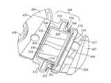
- FIG. 4is a top perspective view of a suspension assembly according to an embodiment of the present invention, after placement of the microactuator but before electrical connection of the microactuator.
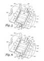
- FIG. 5is an expanded view of the region labeled 5 in FIG. 4 .
- FIG. 6is an expanded view of the region labeled 5 in FIG. 4 , except after electrical connection of the microactuator.
- FIG. 7is an expanded view of the region labeled 5 in FIG. 4 , except before placement of the microactuator.
- FIG. 8is a top plan view of a suspension assembly component that includes a mounting plate and a microactuator mounting structure, according to an embodiment of the present invention.
- FIG. 1is top view of a disk drive 100 that is capable of including an embodiment of the present invention.
- the disk drive 100includes a disk drive base 102 .
- the disk drive 100further includes a spindle 106 , rotably mounted on the disk drive base 102 , for rotating a disk 104 that is mounted on the spindle 106 .
- the rotation of the disks 104establishes air flow through optional recirculation filter 108 .
- disk drive 100may have only a single disk 104 , or alternatively, two or more disks.
- the disk drive 100further includes a rotary coarse actuator 110 that is rotably mounted on disk drive base 102 .
- the rotary coarse actuator 110includes an actuator arm 114 that supports a head gimbal assembly (HGA) 118 .
- HGAhead gimbal assembly
- Voice coil motor 112rotates the actuator 110 through a limited angular range so that the HGA 118 may be desirably positioned relative to one or more tracks of information on the disk 104 .
- the disk drive 100will include one HGA 118 per disk surface, but depopulated disk drives are also contemplated in which fewer HGAs are used. Under non-operating conditions the HGAs may be parked on ramp 120 , for example to avoid contact with the disk 104 when it is not spinning. Electrical signals to/from the HGA 118 are carried to other drive electronics, in part via a flex cable (not shown) and a flex cable bracket 116 .
- FIG. 2is a bottom perspective view of an HGA 200 that is capable of including an embodiment of the present invention.
- the HGA 200includes a load beam 202 , and a read head 210 for reading and writing data from and to a magnetic disk (e.g. disk 104 ).
- the read head 210includes a slider substrate having an air bearing surface (the label 210 points to this surface) and an opposing top surface (not visible in the view of FIG. 2 ).
- the slider substratepreferably comprises AlTiC, although another ceramic or silicon might also be used.
- the slider substrate of the read head 210also includes a trailing face 212 that includes a read/write transducer (too small to be practically shown in the view of FIG.
- the read/write transduceris preferably an inductive magnetic write transducer merged with a magneto-resistive read transducer.
- the purpose of the load beam 202is to provide limited vertical compliance for the read head 210 to follow vertical undulations of the surface of a disk (e.g. disk 104 of FIG. 1 ) as it rotates, and to preload the air bearing surface of the read head 210 against the disk surface by a preload force that is commonly referred to as the “gram load.”
- the HGA 200also includes a laminated flexure 204 attached to the load beam 202 .
- the laminated flexure 204includes a tongue 206 that has a read head bonding surface.
- the head 210is attached to the read head bonding surface of the tongue 206 of the laminated flexure 204 . Only a portion of the tongue 206 is visible in the view of FIG. 2 because the read head 210 partially obscures it.
- a first purpose of the laminated flexure 204is to provide compliance for the head 210 to follow pitch and roll angular undulations of the surface of the disk (e.g.
- a second purpose of the laminated flexure 204is to provide a plurality of electrical paths to facilitate signal transmission to/from the read head 210 .
- the laminated flexure 204includes a plurality of electrically conductive traces 218 that are defined in an electrically conductive (e.g. copper) sub-layer of the laminated flexure 204 . Electrically conductive traces 218 are isolated from a support layer (e.g. stainless steel) by a dielectric layer (e.g. polyimide).
- the load beam 202includes hinge plates 222 and 224 , and is attached to a mounting plate 220 via the hinge plates 222 and 224 and a microactuator mounting structure 300 .
- These componentsmay be made of stainless steel, and their attachments to each other may be made by a plurality of spot welds, for example.
- the load beam 202may have integral hinge plate regions rather than being assembled with separate hinge plate components, so that the load beam 202 and its hinge plates would be a single component having material continuity.
- the load beam 202 with its hinge plates 222 , 224 (if any), the microactuator mounting structure 300 , and the mounting plate 220may together be referred to as a “suspension assembly.” Accordingly, the mounting plate 220 may also be referred to as a suspension assembly mounting plate 220 . In certain preferred embodiments, the suspension assembly mounting plate 220 includes a swage boss 226 to facilitate attachment of the suspension assembly to an actuator arm (e.g. actuator arm 114 ).
- the suspension assembly mounting plate 220may also be referred to as a “swage mounting plate.”
- the laminated flexure 204may be considered to also pertain to the “suspension assembly.”
- the term “suspension assembly”may refer to only the load beam 202 with its hinge plates 222 , 224 (if any), and the mounting plate 220 .
- FIG. 3is an expanded view of the region of the HGA 200 that is labeled 3 in FIG. 2 .
- a microactuator mounting structure 300is seen to extend from the suspension assembly mounting plate 220 .
- the microactuator mounting structure 300is seen to be a separate sub-component that is attached to the suspension assembly mounting plate 220 (e.g. by a plurality of spot welds).
- the microactuator mounting structure 300 and the suspension assembly mounting plate 220may be a single component having material continuity rather than being an assembly of subcomponents.
- the microactuator mounting structure 300may include at least one compliant arm 310 so that the microactuator can move a distal portion 318 relative to an anchored portion 316 of the microactuator mounting structure 300 .
- the microactuator mounting structure 300includes two compliant arms 310 and 312 , so that the microactuator mounting structure encompasses a window 314 .
- the window 314is dimensioned so that it can be spanned by microactuator 330 .
- the microactuator mounting structure 300can be designed to have a single compliant arm (e.g. centered on a longitudinal axis of the suspension assembly) so that the microactuator mounting structure 300 would be generally I-shaped between distal and root portions.
- Such embodimentsmay have two microactuators on either side of the I-shape that span the distance from the distal portion to the root portion.
- the load beam 202extends from the distal portion 318 of the microactuator mounting structure 300 , in that the load beam 202 includes the hinge plates 222 and 224 that are attached to and extend from the distal portion 318 of the microactuator mounting structure 300 .
- the hinge plates 222 , 224 and the load beam 202can be a single component having material continuity (rather than being an assembly of subcomponents as shown in FIG. 3 ).
- FIG. 4is a top perspective view of a suspension assembly 400 according to an embodiment of the present invention, after placement of a microactuator 430 but before electrical connection of the microactuator 430 .
- the suspension assembly 400includes a load beam 402 and a laminated flexure 404 attached to the load beam 402 .
- the load beam 402includes hinge plates 422 and 424 , and is attached to a suspension assembly mounting plate 420 via the hinge plates 422 and 424 .
- These componentsmay be made of stainless steel, and their attachments to each other may be made by spot welding, for example.
- the load beam 402may have integral hinge plate regions rather than being assembled with separate hinge plate components, so that the load beam 402 and its hinge plates would be a single component having material continuity.
- the suspension assembly mounting plate 420includes a swage boss 426 to facilitate attachment of the suspension assembly to an actuator arm (e.g. actuator arm 114 ).
- FIG. 5is an expanded view of the region of the suspension assembly 400 that is labeled 5 in FIG. 4 .
- the suspension assembly mounting plate 420can be seen to include a microactuator mounting structure 500 extending from the suspension assembly mounting plate 420 .
- the microactuator mounting structure 500includes a partially etched well 540 into which the microactuator 430 may be placed.
- the microactuator 430is adhered to the microactuator mounting structure 500 by an adhesive (e.g. UV cured epoxy, thermal set epoxy, etc), and such adhesive or another encapsulate material may be disposed around the periphery of the microactuator 430 and within the partially etched well to help prevent particle shedding.
- an adhesivee.g. UV cured epoxy, thermal set epoxy, etc
- the microactuator mounting structure 500includes at least one compliant arm 510 so that the microactuator 430 can move a distal portion 518 relative to an anchored portion 516 of the microactuator mounting structure 500 .
- the microactuator mounting structure 500includes two compliant arms 510 and 512 , so that the microactuator mounting structure encompasses a window 514 .
- the window 514is dimensioned so that it can be spanned by microactuator 430 .
- the microactuator mounting structure 500can be designed to have a single compliant arm so that the microactuator mounting structure 500 would be generally I-shaped between distal and root portions. Such embodiments may have two microactuators on either side of the I-shape that span the distance from the distal portion to the root portion.
- the load beam 402extends from the distal portion 518 of the microactuator mounting structure 500 , in that the load beam 402 includes the hinge plates 422 and 424 that are attached to and extend from the distal portion 518 of the microactuator mounting structure 500 .
- the hinge plates 422 , 424 and the load beam 402can be a single component having material continuity (rather than being an assembly of subcomponents as shown in FIG. 5 ).
- the distal portion 518 of the microactuator mounting structure 500may optionally include a adhesive-limiting trench 570 to help prevent adhesive from reaching (and potentially undesirably affecting the structural characteristics of) the hinge plates 422 , 424 .
- the microactuator mounting structure 500 of the suspension assembly 400includes a stainless steel surface having two regions 550 and 552 that are coated with gold.
- one or more gold coatingscan be disposed on a stainless steel surface of the suspension assembly mounting plate 420 outside but adjacent the anchored portion 516 of the microactuator mounting structure 500 .
- a gold coatingmay be disposed on a stainless steel surface of each of the hinge plates 422 , 424 , outside but adjacent the distal portion 518 of the microactuator mounting structure 500 .
- the gold coatingsbe disposed near enough to the microactuator 430 to facilitate electrical connection thereto.
- the two gold-coated regions 550 and 552 of the stainless steel surface of the microactuator mounting structure 500include partial etched trenches 560 and 562 , respectively.
- the microactuator 430includes top electrodes 432 and 436 , separated by an isolation region 434 .
- the top electrodes 432 and 436are not electrically connected to the two gold-coated regions 550 and 552 of the stainless steel surface of the microactuator mounting structure 500 .
- the microactuator 430is a piezoelectric microactuator that is polarized differently beneath the top electrode 432 than it is beneath the top electrode 436 , to facilitate differential motion despite the application of a common electrical field from a common bottom electrode (not shown).
- the microactuatoris a piezoelectric microactuator that is polarized similarly beneath the top electrode 432 and the top electrode 436 , with differential motion being created by the application of different or opposite voltages to one opposing bottom electrode (not shown) versus another.
- FIG. 6is an expanded view of the region labeled 5 in FIG. 4 (of the suspension assembly 400 ), except after electrical connection of the top electrodes 432 and 436 of the microactuator 430 to the two gold-coated regions 550 and 552 of the stainless steel surface of the microactuator mounting structure 500 .
- FIG. 7is an expanded view of the region labeled 5 in FIG. 4 (of the suspension assembly 400 ), except before placement of the microactuator 430 .
- the top electrodes 432 and 436 of the microactuator 430have been electrically connected to the two gold-coated regions 550 and 552 of the stainless steel surface of the microactuator mounting structure 500 , by beads 650 and 652 of epoxy adhesive that is doped with silver particles.
- epoxy adhesivethat is doped with silver particles.
- solder or gold wire stitchingmay be used to make the electrical connections.
- solderif solder is used and the microactuator is a piezoelectric microactuator, then it may be desirable for the solder to be a low temp-melting-point since it should not need to get so hot that the piezoelectric material (e.g. PZT) is depolarized.
- the gold coating in gold-coated regions 550 and 552may advantageously diminish or prevent an electrochemical reaction that could cause an undesirable oxidation layer to form on the stainless steel surface at the connection locations, and thereby improve the reliability of the electrical connections.
- the partial etched trenches 560 and 562may also improve the reliability of the electrical connection of the top electrodes 432 and 436 of the microactuator 430 to the two gold-coated regions 550 and 552 .
- the microactuatormay include two piezoelectric elements, each connected to at least one of the plurality of conductive traces (e.g. conductive traces 218 ).
- each piezoelectric elementcan be separately or differently energized to create a desired motion of the distal portion of the microactuator mounting portion relative to the anchor portion thereof.
- the microactuatorincludes one piezoelectric element (as shown in FIG. 5 ) having bottom electrodes that are electrically connected to two of the plurality of conductive traces. In such an embodiment, a different voltage can be applied to different portions of the piezoelectric element to create a desired motion of the distal portion of the microactuator mounting portion relative to the anchor portion thereof.
- the microactuator 430includes one piezoelectric element having a common bottom electrode that is electrically connected to only a single one of the plurality of conductive traces (with the top electrode or electrodes connected to ground via the suspension assembly stainless steel structure).
- the piezoelectric elementis preferably polarized differently beneath one surface electrode versus another, to facilitate differential motion despite the application of a common voltage from the single conductive trace.
- the side of the piezoelectric microactuator that is groundedmay be grounded via connection to the stainless steel parts of the suspension assembly (used as the ground conductor rather than or in addition to a ground trace of the laminated flexure).
- FIG. 8is a top plan view of a suspension assembly component 800 according to an embodiment of the present invention.
- the suspension assembly component 800includes a mounting plate portion 820 and a microactuator mounting structure 801 extending from the mounting plate portion 820 .
- the mounting plate portion 820 and the microactuator mounting structure 801are shown to be a single component having material continuity rather than being an assembly of subcomponents.
- the microactuator mounting structure 801includes a partially etched well 840 into which a microactuator may be placed.
- the microactuator mounting structure 801includes at least one compliant arm 810 so that a microactuator can move a distal portion 818 relative to an anchored portion 816 of the microactuator mounting structure 801 .
- the microactuator mounting structure 801includes two compliant arms 810 and 812 , so that the microactuator mounting structure encompasses a window 814 .
- the window 814is dimensioned so that it can be spanned by a microactuator.
- the distal portion 818 of the microactuator mounting structure 801includes a stainless steel surface having two regions 850 and 852 that are coated with gold.
- one or more gold coatingscan be disposed on a stainless steel surface of the mounting plate portion 820 , for example outside but adjacent the anchored portion 816 of the microactuator mounting structure 801 .
- the gold coatingsbe disposed near enough to the partially etched well 840 to facilitate electrical connection to a microactuator placed therein.
- the two gold-coated regions 850 and 852 of the stainless steel surface of the microactuator mounting structure 801include partial etched trenches 860 and 862 , respectively, which may increase the reliability of electrical connections made thereto.
- the distal portion 818 of the microactuator mounting structure 801may optionally also include an adhesive-limiting trench 870 .
Landscapes
- Supporting Of Heads In Record-Carrier Devices (AREA)
- Moving Of The Head To Find And Align With The Track (AREA)
Abstract
Description
Claims (18)
Priority Applications (5)
| Application Number | Priority Date | Filing Date | Title |
|---|---|---|---|
| US12/725,730US8542465B2 (en) | 2010-03-17 | 2010-03-17 | Suspension assembly having a microactuator electrically connected to a gold coating on a stainless steel surface |
| CN201110068572.XACN102194471B (en) | 2010-03-17 | 2011-03-17 | There is the suspension subassembly of the microdrive of the gold plating be electrically connected on stainless steel surfaces |
| HK11112275.8AHK1158355B (en) | 2010-03-17 | 2011-11-14 | Suspension assembly having a microactuator electrically connected to a gold coating on a stainless steel surface |
| US14/012,449US9099131B1 (en) | 2010-03-17 | 2013-08-28 | Suspension assembly having a microactuator electrically connected to a gold coating on a stainless steel surface |
| US14/802,329US9472218B2 (en) | 2010-03-17 | 2015-07-17 | Suspension assembly having a microactuator electrically connected to a gold coating on a stainless steel surface |
Applications Claiming Priority (1)
| Application Number | Priority Date | Filing Date | Title |
|---|---|---|---|
| US12/725,730US8542465B2 (en) | 2010-03-17 | 2010-03-17 | Suspension assembly having a microactuator electrically connected to a gold coating on a stainless steel surface |
Related Child Applications (1)
| Application Number | Title | Priority Date | Filing Date |
|---|---|---|---|
| US14/012,449DivisionUS9099131B1 (en) | 2010-03-17 | 2013-08-28 | Suspension assembly having a microactuator electrically connected to a gold coating on a stainless steel surface |
Publications (2)
| Publication Number | Publication Date |
|---|---|
| US20110228425A1 US20110228425A1 (en) | 2011-09-22 |
| US8542465B2true US8542465B2 (en) | 2013-09-24 |
Family
ID=44602417
Family Applications (3)
| Application Number | Title | Priority Date | Filing Date |
|---|---|---|---|
| US12/725,730Active2030-11-04US8542465B2 (en) | 2010-03-17 | 2010-03-17 | Suspension assembly having a microactuator electrically connected to a gold coating on a stainless steel surface |
| US14/012,449ActiveUS9099131B1 (en) | 2010-03-17 | 2013-08-28 | Suspension assembly having a microactuator electrically connected to a gold coating on a stainless steel surface |
| US14/802,329ActiveUS9472218B2 (en) | 2010-03-17 | 2015-07-17 | Suspension assembly having a microactuator electrically connected to a gold coating on a stainless steel surface |
Family Applications After (2)
| Application Number | Title | Priority Date | Filing Date |
|---|---|---|---|
| US14/012,449ActiveUS9099131B1 (en) | 2010-03-17 | 2013-08-28 | Suspension assembly having a microactuator electrically connected to a gold coating on a stainless steel surface |
| US14/802,329ActiveUS9472218B2 (en) | 2010-03-17 | 2015-07-17 | Suspension assembly having a microactuator electrically connected to a gold coating on a stainless steel surface |
Country Status (2)
| Country | Link |
|---|---|
| US (3) | US8542465B2 (en) |
| CN (1) | CN102194471B (en) |
Cited By (66)
| Publication number | Priority date | Publication date | Assignee | Title |
|---|---|---|---|---|
| US8665567B2 (en) | 2010-06-30 | 2014-03-04 | Western Digital Technologies, Inc. | Suspension assembly having a microactuator grounded to a flexure |
| US8873202B2 (en)* | 2012-10-30 | 2014-10-28 | Kabushiki Kaisha Toshiba | Head gimbal assembly in which flexure swing is suppressed and disk device including the same |
| US8891206B2 (en) | 2012-12-17 | 2014-11-18 | Hutchinson Technology Incorporated | Co-located gimbal-based dual stage actuation disk drive suspensions with motor stiffener |
| US8896970B1 (en) | 2013-12-31 | 2014-11-25 | Hutchinson Technology Incorporated | Balanced co-located gimbal-based dual stage actuation disk drive suspensions |
| US8896969B1 (en) | 2013-05-23 | 2014-11-25 | Hutchinson Technology Incorporated | Two-motor co-located gimbal-based dual stage actuation disk drive suspensions with motor stiffeners |
| US8896968B2 (en) | 2012-10-10 | 2014-11-25 | Hutchinson Technology Incorporated | Co-located gimbal-based dual stage actuation disk drive suspensions with dampers |
| US8908319B1 (en) | 2013-04-18 | 2014-12-09 | Western Digital Technologies, Inc. | Disk drive with slow acting desiccant |
| US8908325B1 (en) | 2013-03-08 | 2014-12-09 | Western Digital Technologies, Inc. | Threaded disk clamping element with step on disk contact surface |
| US8941952B1 (en) | 2014-06-10 | 2015-01-27 | Western Digital Technologies, Inc. | Disk drive head stack assembly having a flexible printed circuit with bond pads having reduced capacitance |
| US8941951B2 (en) | 2012-11-28 | 2015-01-27 | Hutchinson Technology Incorporated | Head suspension flexure with integrated strain sensor and sputtered traces |
| US8970984B1 (en) | 2014-04-29 | 2015-03-03 | Western Digital Technologies, Inc. | Grooved cylindrical seal with increased radial clearance for reduced cost disk drive spindle |
| US8995094B1 (en) | 2014-02-28 | 2015-03-31 | Western Digital Technologies, Inc. | Disk drive head suspension with a dual dimple and a flexure tongue with a piezoelectric microactuator |
| US9001469B2 (en) | 2012-03-16 | 2015-04-07 | Hutchinson Technology Incorporated | Mid-loadbeam dual stage actuated (DSA) disk drive head suspension |
| US9001471B2 (en) | 2012-09-14 | 2015-04-07 | Hutchinson Technology Incorporated | Co-located gimbal-based dual stage actuation disk drive suspensions |
| US9007716B1 (en) | 2012-09-24 | 2015-04-14 | Western Digital Technologies, Inc. | Spindle motor magnet diameter increase above head plane |
| US9007726B2 (en) | 2013-07-15 | 2015-04-14 | Hutchinson Technology Incorporated | Disk drive suspension assembly having a partially flangeless load point dimple |
| US9019657B1 (en) | 2013-03-13 | 2015-04-28 | Western Digital Technologies, Inc. | Coined VCM tab to limit cover deflection under pinch load |
| US9025284B1 (en) | 2014-02-26 | 2015-05-05 | Western Digital Technologies, Inc. | Disk drive with self sealing screw attachment of actuator pivot |
| US9025285B1 (en) | 2009-12-16 | 2015-05-05 | Magnecomp Corporation | Low resistance interface metal for disk drive suspension component grounding |
| US9036295B1 (en) | 2011-12-20 | 2015-05-19 | Western Digital Technologies, Inc. | Information storage device with a damping insert sheet between a housing bay and a disk drive |
| US9058851B1 (en) | 2014-07-02 | 2015-06-16 | Western Digital Technologies, Inc. | Information-storage device including an oxygen absorbing device |
| US9064510B1 (en)* | 2014-08-06 | 2015-06-23 | Kabushiki Kaisha Toshiba | Suspension assembly, head suspension assembly and disk device with the same |
| US9099131B1 (en) | 2010-03-17 | 2015-08-04 | Western Digital Technologies, Inc. | Suspension assembly having a microactuator electrically connected to a gold coating on a stainless steel surface |
| US9099153B2 (en) | 2013-04-03 | 2015-08-04 | Western Digital Technologies, Inc. | Storage device with a cover supporting portion |
| US9105288B1 (en)* | 2014-03-11 | 2015-08-11 | Magnecomp Corporation | Formed electrical contact pad for use in a dual stage actuated suspension |
| US9116066B1 (en) | 2012-04-27 | 2015-08-25 | Western Digital Technologies, Inc. | Devices and methods for system-level disk drive vibration and shock testing |
| US9123387B1 (en) | 2014-08-21 | 2015-09-01 | WD Media, LLC | Magnetic recording drives with active photocatalytic filtration |
| US9123367B1 (en)* | 2014-06-16 | 2015-09-01 | Intri-Plex Technologies, Inc. | Swage mount having a mixture of a conductive material and a coating material and method of manufacturing the swage mount |
| US9129639B1 (en) | 2012-11-08 | 2015-09-08 | Western Digital Technologies, Inc. | Method of imbalance correction using a grooved disk clamp |
| US9147436B2 (en) | 2012-04-25 | 2015-09-29 | Western Digital Technologies, Inc. | Slim form factor disk drive comprising disk drive enclosure having an insular raised region |
| US9153262B1 (en) | 2015-03-26 | 2015-10-06 | Western Digital Technologies, Inc. | Disk drive actuator having a radially stepped pivot bore |
| US9159205B1 (en) | 2013-12-18 | 2015-10-13 | Western Digital Technologies, Inc. | Tamper-evident seals having adhesive-free areas to minimize rework time |
| US9165580B2 (en) | 2013-12-10 | 2015-10-20 | Western Digital Technologies, Inc. | Disk drive head suspension tail with stiffened edge alignment features |
| US9171560B1 (en) | 2014-09-26 | 2015-10-27 | Western Digital Technologies, Inc. | Sloping transition on a ramp of a hard disk drive |
| US9171583B1 (en) | 2015-03-23 | 2015-10-27 | Western Digital Technologies, Inc. | Disk drive having a top cover channel vented to a central cavity via a peripheral clearance gap |
| US9183889B1 (en) | 2015-03-23 | 2015-11-10 | Western Digital Technologies, Inc. | Disk drive having a top cover channel vented to a central cavity via a hole through a bottom land |
| US9190114B1 (en) | 2015-02-09 | 2015-11-17 | Western Digital Technologies, Inc. | Disk drive filter including fluorinated and non-fluorinated nanopourous organic framework materials |
| US9196275B1 (en) | 2014-03-12 | 2015-11-24 | Western Digital Technologies, Inc. | Magnetic head separator fin material to prevent particulate contamination on slider |
| US9196301B1 (en) | 2011-10-14 | 2015-11-24 | Western Digital Technologies, Inc. | Suspension clamp for clamping a disk drive suspension to an actuator arm |
| US9196292B1 (en) | 2015-02-05 | 2015-11-24 | Western Digital Technologies, Inc. | Rotary spindle having a disk clamp bottom land facing and in contact with a shaft top land |
| US9208825B1 (en) | 2013-08-07 | 2015-12-08 | Western Digital Technologies, Inc. | Disk drive having a conformal peripheral foil seal having an opening covered by a central metal cap |
| US9214174B1 (en) | 2010-10-29 | 2015-12-15 | Western Digital Technologies, Inc. | Method of manufacturing a disk drive head gimbal assembly having a flexure tail with folded bond pads |
| US9245555B2 (en) | 2010-05-24 | 2016-01-26 | Hutchinson Technology Incorporated | Low resistance ground joints for dual stage actuation disk drive suspensions |
| US9251817B1 (en) | 2014-06-30 | 2016-02-02 | Magnecomp Corporation | Microactuator grounding through oversized via in a disk drive suspension flexure circuit |
| US9263070B1 (en) | 2014-11-05 | 2016-02-16 | Western Digital Technologies, Inc. | Actuator pivot assembly including a bonding adhesive barrier configured to reduce contamination |
| US9299384B1 (en) | 2012-08-02 | 2016-03-29 | Western Digital Technologies, Inc. | Ultra-thin HDD embedded disk clamp design |
| US9324344B1 (en) | 2013-12-10 | 2016-04-26 | Western Digital Technologies, Inc. | Disk drive head suspension tail with ground pad outside of bonding region |
| US9330695B1 (en) | 2013-12-10 | 2016-05-03 | Western Digital Technologies, Inc. | Disk drive head suspension tail with a noble metal layer disposed on a plurality of structural backing islands |
| US9379311B1 (en) | 2005-12-09 | 2016-06-28 | Western Digital Technologies, Inc. | Apparatus for manufacturing piezoelectric actuators |
| US9390736B1 (en) | 2014-03-13 | 2016-07-12 | Western Digital Technologies, Inc. | Magnetic head separator connected to a ramp |
| US9406333B1 (en) | 2015-11-10 | 2016-08-02 | Western Digital Technologies, Inc. | Disk drive having a stationary plate between disks with grooves adjacent fastener holes |
| US9431042B2 (en) | 2014-01-03 | 2016-08-30 | Hutchinson Technology Incorporated | Balanced multi-trace transmission in a hard disk drive flexure |
| US9472242B1 (en) | 2015-06-05 | 2016-10-18 | Western Digital Technologies, Inc. | Hard disk drive enclosure base with feed through flexure design and accompanying flexure |
| US9508393B1 (en) | 2015-06-25 | 2016-11-29 | Western Digital Technologies, Inc. | Hard disk drive enclosure base with a helium sealed gasket |
| US9514773B2 (en) | 2008-08-20 | 2016-12-06 | Western Digital Technologies, Inc. | Head stack assembly with a flexible printed circuit having a mouth centered between arms |
| US9524738B1 (en) | 2015-06-25 | 2016-12-20 | Western Digital Technologies, Inc. | Disk drive head gimbal assembly having a flexure tail with a dielectric layer that has regions of lesser thickness |
| US9558771B2 (en) | 2014-12-16 | 2017-01-31 | Hutchinson Technology Incorporated | Piezoelectric disk drive suspension motors having plated stiffeners |
| US9564154B2 (en) | 2014-12-22 | 2017-02-07 | Hutchinson Technology Incorporated | Multilayer disk drive motors having out-of-plane bending |
| US9564156B1 (en) | 2016-01-27 | 2017-02-07 | Western Digital Technologies, Inc. | Head gimbal assembly having a flexure tail with cover layer standoff islands |
| US9583125B1 (en) | 2009-12-16 | 2017-02-28 | Magnecomp Corporation | Low resistance interface metal for disk drive suspension component grounding |
| US9633680B2 (en) | 2010-10-29 | 2017-04-25 | Western Digital Technologies, Inc. | Head suspension having a flexure tail with a covered conductive layer and structural layer bond pads |
| US9646638B1 (en) | 2016-05-12 | 2017-05-09 | Hutchinson Technology Incorporated | Co-located gimbal-based DSA disk drive suspension with traces routed around slider pad |
| US9662753B1 (en) | 2014-03-10 | 2017-05-30 | Western Digital Technologies, Inc. | Disk drive spindle with fluid journal bearing having increased radial clearance in axial end regions |
| US9734852B2 (en) | 2015-06-30 | 2017-08-15 | Hutchinson Technology Incorporated | Disk drive head suspension structures having improved gold-dielectric joint reliability |
| US9824704B2 (en) | 2015-02-17 | 2017-11-21 | Hutchinson Technology Incorporated | Partial curing of a microactuator mounting adhesive in a disk drive suspension |
| US9908167B1 (en) | 2015-03-02 | 2018-03-06 | Western Digital Technologies, Inc. | Disk drive tolerance ring with edge rounding from opposite major faces |
Families Citing this family (19)
| Publication number | Priority date | Publication date | Assignee | Title |
|---|---|---|---|---|
| US8498082B1 (en)* | 2011-03-23 | 2013-07-30 | Magnecomp Corporation | DSA suspension with improved microactuator stroke length |
| US8446694B1 (en)* | 2011-06-14 | 2013-05-21 | Western Digital Technologies, Inc. | Disk drive head suspension assembly with embedded in-plane actuator at flexure tongue |
| US8593764B1 (en)* | 2011-06-14 | 2013-11-26 | Western Digital Technologies, Inc. | Method for fine actuation of a head during operation of a disk drive |
| CN102915746B (en)* | 2011-08-04 | 2016-08-24 | 新科实业有限公司 | Cantilever part, magnetic head folding piece combination and hard disk drive unit |
| US8451563B1 (en)* | 2011-12-20 | 2013-05-28 | Western Digital (Fremont), Llc | Method for providing a side shield for a magnetic recording transducer using an air bridge |
| CN104205216A (en) | 2012-03-22 | 2014-12-10 | 哈特奇桑科技公司 | Grounding Features for Disk Drive Head Suspension Flexures |
| WO2014035591A1 (en) | 2012-08-31 | 2014-03-06 | Hutchinson Technology Incorporated | Damped dual stage actuation disk drive suspensions |
| US8980109B1 (en) | 2012-12-11 | 2015-03-17 | Western Digital (Fremont), Llc | Method for providing a magnetic recording transducer using a combined main pole and side shield CMP for a wraparound shield scheme |
| US8914969B1 (en) | 2012-12-17 | 2014-12-23 | Western Digital (Fremont), Llc | Method for providing a monolithic shield for a magnetic recording transducer |
| US8982513B1 (en) | 2013-05-21 | 2015-03-17 | Western Digital Technologies, Inc. | Disk drive head suspension with dual piezoelectric elements adhered to rotary-actuated and non-actuated portions of a structural layer of a tongue of a laminated flexure |
| US8792214B1 (en) | 2013-07-23 | 2014-07-29 | Hutchinson Technology Incorporated | Electrical contacts to motors in dual stage actuated suspensions |
| US8675314B1 (en) | 2013-08-21 | 2014-03-18 | Hutchinson Technology Incorporated | Co-located gimbal-based dual stage actuation disk drive suspensions with offset motors |
| JP6491837B2 (en) | 2013-09-03 | 2019-03-27 | ハッチンソン テクノロジー インコーポレイテッドHutchinson Technology Incorporated | Motor polarity test of two-stage disk drive head suspension |
| US9679593B2 (en)* | 2014-09-22 | 2017-06-13 | Seagate Technology Llc | Circuit connection pad design for improved electrical robustness using conductive epoxy |
| CN107250440B (en) | 2015-01-16 | 2019-07-30 | 哈钦森技术股份有限公司 | Gold electroplating solutions and methods |
| US10594029B2 (en)* | 2016-09-30 | 2020-03-17 | Intel Corporation | Actuatable and adaptable metamaterials integrated in package |
| US10891979B1 (en)* | 2020-04-17 | 2021-01-12 | Western Digital Technologies, Inc. | Data storage device calibrating bias for fine actuators |
| US11501797B2 (en)* | 2020-05-15 | 2022-11-15 | Magnecomp Corporation | Actuator joint with non-straight edge |
| JP7731825B2 (en)* | 2022-03-03 | 2025-09-01 | 日本発條株式会社 | Disk drive suspension |
Citations (22)
| Publication number | Priority date | Publication date | Assignee | Title |
|---|---|---|---|---|
| US5521778A (en) | 1994-08-30 | 1996-05-28 | International Business Machines Corporation | Disk drive with primary and secondary actuator drives |
| US5754368A (en)* | 1995-10-27 | 1998-05-19 | Tdk Corporation | Suspension, slider-suspension assembly, assembly carriage device and manufacturing method of suspension |
| US6278587B1 (en) | 1999-04-21 | 2001-08-21 | Magnecomp Corp. | Positive coupling of piezoelectric devices in disk drive suspensions |
| US6307715B1 (en)* | 1996-08-30 | 2001-10-23 | Read-Rite Corporation | Head suspension having reduced torsional vibration |
| US20020075606A1 (en)* | 2000-12-15 | 2002-06-20 | Nhk Spring Co., Ltd. | Suspension for disc drive |
| US20020118492A1 (en)* | 2001-02-23 | 2002-08-29 | Mitsuru Watanabe | Magnetic head device having suspension with microactuator bonded thereto |
| US6490228B2 (en) | 2001-02-16 | 2002-12-03 | Koninklijke Philips Electronics N.V. | Apparatus and method of forming electrical connections to an acoustic transducer |
| US6856075B1 (en) | 2001-06-22 | 2005-02-15 | Hutchinson Technology Incorporated | Enhancements for adhesive attachment of piezoelectric motor elements to a disk drive suspension |
| US7064928B2 (en)* | 2002-10-11 | 2006-06-20 | Sae Magnetics (H.K.) Ltd. | Method and apparatus for providing an additional ground pad and electrical connection for grounding a magnetic recording head |
| US7177119B1 (en) | 2000-12-05 | 2007-02-13 | Hutchinson Technology Incorporated | Microactuated head suspension with ring springs |
| US7218481B1 (en)* | 2002-10-07 | 2007-05-15 | Hutchinson Technology Incorporated | Apparatus for insulating and electrically connecting piezoelectric motor in dual stage actuator suspension |
| US7322241B2 (en) | 2005-01-20 | 2008-01-29 | Oki Electric Industry Co., Ltd. | Acceleration sensor with redundant contact holes |
| US7382582B1 (en)* | 2000-03-21 | 2008-06-03 | Magnecomp Corporation | Reduced cross talk in wireless suspensions |
| US7417830B1 (en) | 2005-08-31 | 2008-08-26 | Magnecomp Corporation | Head gimbal assembly with dual-mode piezo microactuator |
| US7459835B1 (en) | 2006-03-06 | 2008-12-02 | Magnecomp Corporation | Loading-protected bending microactuator in additive suspensions |
| US20090190263A1 (en)* | 2006-06-22 | 2009-07-30 | Yoichi Miura | Substrate for suspension, and production process thereof |
| US20090294740A1 (en) | 2006-04-26 | 2009-12-03 | Kulite Semiconductor Products, Inc. | Method and apparatus for preventing catastrophic contact failure in ultra high temperature piezoresistive sensors and transducers |
| US20100177445A1 (en) | 2009-01-15 | 2010-07-15 | Nhk Spring Co., Ltd. | Wiring connecting structure for piezoelectric actuator, piezoelectric actuator, and head suspension |
| US20100271735A1 (en) | 2009-04-24 | 2010-10-28 | Magnecomp Corporation | Wireless Microactuator Motor Assembly for Use in a Hard Disk Drive Suspension, and Mechanical and Electrical Connections Thereto |
| US7832082B1 (en)* | 2006-10-10 | 2010-11-16 | Hutchinson Technology Incorporated | Method for manufacturing an integrated lead suspension component |
| US7929252B1 (en)* | 2006-10-10 | 2011-04-19 | Hutchinson Technology Incorporated | Multi-layer ground plane structures for integrated lead suspensions |
| US8149542B2 (en) | 2008-12-25 | 2012-04-03 | Nhk Spring Co., Ltd. | Wiring connecting structure for piezoelectric element, wiring connecting method, piezoelectric actuator, and head suspension |
Family Cites Families (365)
| Publication number | Priority date | Publication date | Assignee | Title |
|---|---|---|---|---|
| DE3020371C2 (en) | 1980-05-29 | 1985-12-19 | Degussa Ag, 6000 Frankfurt | Process for the pretreatment of stainless steel for direct galvanic gold plating |
| US4422906A (en) | 1981-09-17 | 1983-12-27 | Masami Kobayashi | Process for direct gold plating of stainless steel |
| US5235482A (en) | 1989-11-09 | 1993-08-10 | Rodime Plc | Magnetic disk drive incorporating a mechanically damped base |
| US6600631B1 (en) | 1989-11-27 | 2003-07-29 | Censtor Corp. | Transducer/flexure/conductor structure for electromagnetic read/write system |
| WO1993014495A1 (en) | 1992-01-20 | 1993-07-22 | Fujitsu Limited | Magnetic head assembly, its manufacture, and magnetic disc device |
| US5282103A (en) | 1992-10-07 | 1994-01-25 | Read-Rite Corporation | Magnetic head suspension assembly fabricated with integral load beam and flexure |
| US5334804A (en) | 1992-11-17 | 1994-08-02 | Fujitsu Limited | Wire interconnect structures for connecting an integrated circuit to a substrate |
| US5320272A (en) | 1993-04-02 | 1994-06-14 | Motorola, Inc. | Tin-bismuth solder connection having improved high temperature properties, and process for forming same |
| US6539609B2 (en) | 1994-07-05 | 2003-04-01 | International Business Machines Corporation | Method of forming a head gimbal assembly |
| JPH08111015A (en) | 1994-09-01 | 1996-04-30 | Tdk Corp | Supporting device of magnetic head slider and magnetic head device |
| US5608591A (en) | 1995-06-09 | 1997-03-04 | International Business Machines Corporation | Integrated head-electronics interconnection suspension for a data recording disk drive |
| JPH0922570A (en) | 1995-07-03 | 1997-01-21 | Fujitsu Ltd | Head assembly and magnetic disk device including the head assembly |
| US6284563B1 (en) | 1995-10-31 | 2001-09-04 | Tessera, Inc. | Method of making compliant microelectronic assemblies |
| US6215622B1 (en) | 1996-01-02 | 2001-04-10 | International Business Machines Corporation | Laminated hard disk head suspension and etching process |
| US5914834A (en) | 1996-06-17 | 1999-06-22 | Hutchinson Technology, Inc. | Head suspension assembly with electrical interconnect by slider bond pads and gimbal bonding zones |
| US6101876A (en) | 1996-06-28 | 2000-08-15 | Western Digital Corporation | Method of centering a disk pack of a disk drive |
| US5818662A (en) | 1996-07-15 | 1998-10-06 | International Business Machines Corporation | Static attitude and stiffness control for an integrated suspension |
| US5796552A (en) | 1996-10-03 | 1998-08-18 | Quantum Corporation | Suspension with biaxially shielded conductor trace array |
| US6349017B1 (en) | 1997-02-21 | 2002-02-19 | Read-Rite Corporation | Magnetic head suspension assembly using bonding pads of a slider to an attachment surface of a flexure |
| US5812344A (en) | 1997-05-12 | 1998-09-22 | Quantum Corporation | Suspension with integrated conductor trace array having optimized cross-sectional high frequency current density |
| US5898544A (en) | 1997-06-13 | 1999-04-27 | Hutchinson Technology Incorporated | Base plate-mounted microactuator for a suspension |
| JP3605497B2 (en) | 1997-07-11 | 2004-12-22 | 日本発条株式会社 | Suspension for disk drive |
| US6061206A (en) | 1998-04-15 | 2000-05-09 | Western Digital Corporation | Head stack assembly for a disk drive having a unitary molded plastic E-block |
| US6185067B1 (en) | 1998-06-17 | 2001-02-06 | Western Digital Corporation | Disk drive with reduced thermal expansion induced disk slip |
| US6147831A (en) | 1998-06-18 | 2000-11-14 | Western Digital Corporation | Servo track writer having a servo writer positioning arm with a vibration damper and a method of making a head disk assembly |
| US6052890A (en) | 1998-06-22 | 2000-04-25 | Western Digital Corporation | Method of making a head disk assembly using a propagated light beam to detect a clearance between a disk and a head |
| US6046889A (en) | 1998-09-24 | 2000-04-04 | Western Digital Corporation | Disk drive having a pivot assembly which defines a knife edge facing in a direction perpendicular to the longitudinal axis of an actuator arm |
| US6417979B1 (en) | 1998-10-23 | 2002-07-09 | Western Digital Technologies, Inc. | Disk drive including strain transducer for detecting mechanical shock |
| US6151189A (en) | 1998-12-28 | 2000-11-21 | Western Digital Corporation | Disk drive spindle motor with embedded ionizing source for static charge dissipation |
| US6185074B1 (en) | 1998-12-29 | 2001-02-06 | Western Digital Corporation | Inertial latch having an interposer that prevents the head from leaving the ramp load during a shock event |
| US6151197A (en) | 1998-12-30 | 2000-11-21 | Western Digital Corporation | Water slide suspension assembly having a stiffened vertically offset lift tab |
| US6215616B1 (en) | 1999-01-04 | 2001-04-10 | Western Digital Corporation | Disk drive spindle motor with wire guide insert |
| US6249404B1 (en) | 1999-02-04 | 2001-06-19 | Read-Rite Corporation | Head gimbal assembly with a flexible printed circuit having a serpentine substrate |
| US6292333B1 (en) | 1999-02-11 | 2001-09-18 | Western Digital Technologies, Inc. | Disk drive having an I.D. ramp loading system employing multiple-function spacer structure |
| JP3532439B2 (en) | 1999-03-02 | 2004-05-31 | アルプス電気株式会社 | Magnetic head |
| US6208486B1 (en) | 1999-05-14 | 2001-03-27 | Western Digital Corporation | Spindle motor flange land portion |
| JP2001043647A (en) | 1999-07-15 | 2001-02-16 | Internatl Business Mach Corp <Ibm> | Hard disk drive, slider holding structure, head gimbals assembly and its manufacture |
| JP2001057039A (en) | 1999-08-13 | 2001-02-27 | Sony Corp | Head suspension, head gimbals assembly and actuator |
| US6388873B1 (en) | 1999-08-20 | 2002-05-14 | Western Digital Technologies, Inc. | Disk drive including resilient securing system providing relative movement between side rails and head disk assembly to accommodate side rails engaging guide channels in a chassis |
| US6156982A (en) | 1999-09-24 | 2000-12-05 | Honeywell Inc. | Low current high temperature switch contacts |
| US6272694B1 (en) | 1999-09-24 | 2001-08-14 | International Business Machines Corporation | Enhanced interface for electrostatic discharge garment |
| US6344950B1 (en) | 1999-09-27 | 2002-02-05 | Western Digital Technologies, Inc. | Head disk assembly including ramp having pivoting locational features |
| US6288866B1 (en) | 1999-11-19 | 2001-09-11 | Western Digital Technologies, Inc. | Disk drive including a vibration damping system having a compressible foam and mass damper fixed adjacent to the outer surface of a printed circuit board for reducing noise and vibration |
| US6661617B1 (en) | 1999-12-14 | 2003-12-09 | Seagate Technology Llc | Structure and fabrication process for integrated moving-coil magnetic micro-actuator |
| JP3716164B2 (en) | 2000-02-14 | 2005-11-16 | 株式会社日立グローバルストレージテクノロジーズ | Head support mechanism |
| US6647621B1 (en) | 2000-03-24 | 2003-11-18 | Hutchinson Technology Incorporated | Electrical resistance reduction method for thermosetting conductive epoxy contacts in integrated lead suspensions |
| US6480359B1 (en) | 2000-05-09 | 2002-11-12 | 3M Innovative Properties Company | Hard disk drive suspension with integral flexible circuit |
| JP4156203B2 (en) | 2000-05-22 | 2008-09-24 | 株式会社日立グローバルストレージテクノロジーズ | Suspension for disk unit |
| US6421208B1 (en) | 2000-05-30 | 2002-07-16 | Western Digital Technologies, Inc. | Disk drive employing a voice coil motor comprising a yoke for generating a undirectional magnetic flux and a voice coil partially interacting with the undirectional magnetic flux |
| US6441998B1 (en) | 2000-05-31 | 2002-08-27 | Western Digital Technologies, Inc. | Compensating for vortex shedding in a disk drive for modifying the thickness of an actuator arm |
| US6674600B1 (en) | 2000-05-31 | 2004-01-06 | Western Digital Technologies, Inc. | Disk drive having separate motion sensors for base and actuator |
| US6349464B1 (en) | 2000-05-31 | 2002-02-26 | Western Digital Technologies, Inc. | Method of making a balance-compensated rotary actuator based upon track-follow performance of a rotatable test head stack assembly portion |
| US6502300B1 (en) | 2000-07-31 | 2003-01-07 | Western Digital Technologies, Inc. | Method and apparatus for balancing a rotary actuator by modifying weight distribution characteristics of the rotary actuator for locating an installed head stack assembly portion center-of-gravity along a pivot axis |
| US6529345B1 (en) | 2000-08-31 | 2003-03-04 | Western Digital Technologies, Inc. | Disk drive employing a multi-layer noise-dampening HDA cover |
| US6922308B1 (en) | 2000-09-29 | 2005-07-26 | Western Digital Technologies, Inc. | Disk drive comprising a cover shaped to improve radial and axial shrouding |
| US6466398B1 (en) | 2000-09-30 | 2002-10-15 | Western Digital Technologies, Inc. | Disk drive comprising a cover having slots near a shaft aperture for reducing resonance |
| US6462914B1 (en) | 2000-10-31 | 2002-10-08 | Western Digital Technologies, Inc. | Voice coil motor comprising a voice coil wrapped around a rotary voice coil yoke comprising a low reluctance end and a high reluctance end |
| US6519116B1 (en) | 2000-11-30 | 2003-02-11 | Western Digital Technologies, Inc. | Actuator arm assembly having bearing gap formed between bearing outer race and pivot sleeve for mitigating torque ripple on actuator arm in a disk drive |
| US6535358B1 (en) | 2000-11-30 | 2003-03-18 | Western Digital Technologies, Inc. | Disk drive comprising a plastic molded crash stop with embedded magnet for latching an actuator arm |
| US6757132B1 (en) | 2000-12-27 | 2004-06-29 | Western Digital Technologies, Inc. | Disk drive comprising a snap-on disk clamp |
| US6710980B1 (en) | 2000-12-27 | 2004-03-23 | Western Digital Technologies, Inc. | Disk drive comprising an inertial actuator latch with strip-spring biasing |
| US6529351B1 (en) | 2001-01-31 | 2003-03-04 | Western Digital Technologies, Inc. | Disk drive comprising a voice coil motor having a yoke with a multiple-bend magnetic flux conductor |
| US6469871B1 (en) | 2001-01-31 | 2002-10-22 | Western Digital Technologies, Inc. | Disk drive comprising a bistable latch with bi-level grooves and a spring restraining force |
| US6624983B1 (en) | 2001-02-28 | 2003-09-23 | Western Digital Technologies, Inc. | Mechanical dual stage actuator linkage for a hard disk drive |
| US6693773B1 (en) | 2001-03-30 | 2004-02-17 | Western Digital Technologies, Inc. | Disk drive having a vertically adjustable ramp load |
| US6731470B1 (en) | 2001-03-30 | 2004-05-04 | Western Digital Technologies, Inc. | Pivot bearing cartridge having inner and outer ball bearing sets |
| US6741428B1 (en) | 2001-03-30 | 2004-05-25 | Western Digital Technologies, Inc. | Spindle motor having inner and outer ball bearing sets |
| US6728063B1 (en) | 2001-04-30 | 2004-04-27 | Western Digital Technologies, Inc. | Spindle motor having spindle motor stator for increased head stack assembly access |
| US6979931B1 (en) | 2001-04-30 | 2005-12-27 | Western Digital Technologies, Inc. | Spindle motor having spindle motor stator with laminate layers for increased head stack assembly access |
| US6961212B1 (en) | 2001-04-30 | 2005-11-01 | Western Digital Technologies, Inc. | Shock isolation bearings and travel limit gaps in a spindle motor and disk drive using the same |
| US6661597B1 (en) | 2001-04-30 | 2003-12-09 | Western Digital Technologies, Inc. | Mobile device and disk drive restricted from writing a data storage zone in a mobile environment |
| US7099099B1 (en) | 2001-04-30 | 2006-08-29 | Western Digital Technologies, Inc. | Mobile device and disk drive restricted from reading a data storage zone in a mobile environment |
| US6654200B1 (en) | 2001-05-24 | 2003-11-25 | Western Digital Technologies, Inc. | Disk drive including electrical traces integrally formed upon disk drive housing |
| US6580574B1 (en) | 2001-05-25 | 2003-06-17 | Western Digital Technologies, Inc. | Mobile device comprising a disk storage system protected by a pressure-sensitive detector |
| US6603620B1 (en) | 2001-05-25 | 2003-08-05 | Western Digital Technologies, Inc. | Mobile device comprising a disk storage system protected by a motion detector |
| US6657811B1 (en) | 2001-05-25 | 2003-12-02 | Western Digital Technologies, Inc. | Mobile device and disk drive having a seek current profile responsive to an environment signal |
| US6560065B1 (en) | 2001-05-31 | 2003-05-06 | Western Digital Technologies, Inc. | Disk drive having airflow suppressor comb with curved extension for reduced disk rotation induced airflow |
| US6624966B1 (en) | 2001-05-31 | 2003-09-23 | Western Digital Technologies, Inc. | Disk drive having airflow suppressor comb for reduced disk rotation induced airflow |
| US6628473B1 (en) | 2001-05-31 | 2003-09-30 | Western Digital Technologies, Inc. | Mobile device having disk drive including a data storage zone with a data track pitch configured for use in a mobile environment |
| US6618222B1 (en) | 2001-06-21 | 2003-09-09 | Western Digital Technologies, Inc. | Disk drive having breather shroud |
| US6781780B1 (en) | 2001-06-21 | 2004-08-24 | Western Digital Technologies, Inc. | Method and system for preventing data loss from an off-track write condition in a disk drive by rewriting data buffered from an adjacent track |
| US6707641B1 (en) | 2001-07-31 | 2004-03-16 | Western Digital Technologies, Inc. | Spindle motor having stator rim formed of concentric laminate layers |
| US6594111B1 (en) | 2001-07-31 | 2003-07-15 | Western Digital Technologies, Inc. | Spindle motor having stator rim formed of curved arc segments |
| US6693767B1 (en) | 2001-07-31 | 2004-02-17 | Western Digital Technologies, Inc. | Disk drive having a head disk assembly enclosure including an integrated hinge |
| US6888698B1 (en) | 2001-08-31 | 2005-05-03 | Western Digital Technologies, Inc. | Disk drive including spindle motor hub and damping members for damping disk movement |
| US6704167B1 (en) | 2001-08-31 | 2004-03-09 | Western Digital Technologies, Inc. | Disk drive including damping member disposed upon latch for damping tang-to-latch impact and mitigating tang-to-latch contact |
| US6661603B1 (en) | 2001-09-28 | 2003-12-09 | Western Digital Technologies, Inc. | Disk drive including conductive path between disk drive base and cover through fastener support |
| US6906880B1 (en) | 2001-09-28 | 2005-06-14 | Western Digital Technologies, Inc. | Erasing disk surface by direct current applied on a helical trajectory to minimize erase time |
| US6757137B1 (en) | 2001-09-30 | 2004-06-29 | Magnecomp Corporation | Stiffness controlled disk drive suspension with limiter feature |
| US6549381B1 (en) | 2001-10-23 | 2003-04-15 | Western Digital Technologies, Inc. | Disk drive having actuator motion damper via histeresis energy loss of low energy magnet placed within magnetic field of a voice coil motor |
| JP3631992B2 (en) | 2001-11-13 | 2005-03-23 | 日東電工株式会社 | Printed circuit board |
| US6697217B1 (en) | 2001-11-30 | 2004-02-24 | Western Digital Technologies, Inc. | Disk drive comprising a coating bonded to a printed circuit board assembly |
| US6791791B1 (en) | 2001-11-30 | 2004-09-14 | Western Digital Technologies, Inc. | Disk drive with disks having different disk stiffness, thickness and material combinations |
| US6856492B2 (en) | 2001-11-30 | 2005-02-15 | Western Digital Technologies, Inc. | Pivot bearing cartridge including central pivot element and ball bearing set |
| US6967804B1 (en) | 2001-11-30 | 2005-11-22 | Western Digital Technologies, Inc. | Shock event error logging in a disk drive |
| US6735033B1 (en) | 2001-12-10 | 2004-05-11 | Western Digital Technologies, Inc. | Method for recovering from shock events occurring to a disk drive during data write operations to improve data reliability |
| US6690637B1 (en) | 2001-12-14 | 2004-02-10 | Western Digital Technologies, Inc. | Disk drive including disk clamp with non-symmetric engaged fastener holes and fastener torque |
| US6707637B1 (en) | 2001-12-14 | 2004-03-16 | Western Digital Technologies, Inc. | Disk drive including disk spacer with different side surface patterns |
| CN1498398A (en) | 2002-01-19 | 2004-05-19 | 新科实业有限公司 | Method and apparatus for physical and electrical connection of hard disk microactuator and magnetic head to a drive arm suspension |
| US6801389B1 (en) | 2002-01-31 | 2004-10-05 | Western Digital Technologies, Inc. | Disk drive employing a spindle motor comprising a hub ratchet arm disengaged through angular velocity |
| US6781787B1 (en) | 2002-01-31 | 2004-08-24 | Western Digital Technologies, Inc. | Adjusting seek current profile on the fly |
| US6867946B1 (en) | 2002-01-31 | 2005-03-15 | Western Digital Technologies, Inc. | Disk drive employing a spindle motor comprising a locking spring arm disengaged through stator coil flux |
| US6972926B1 (en) | 2002-01-31 | 2005-12-06 | Western Digital Technologies, Inc. | Disk drive having disk drive housing including airflow suppressor portion |
| US6844996B1 (en) | 2002-01-31 | 2005-01-18 | Western Digital Technologies, Inc. | Disk drive comprising a ratchet arm applied to a disk and disengaged through windage generated by the disk rotating |
| US6781791B1 (en) | 2002-01-31 | 2004-08-24 | Western Digital Technologies, Inc. | Disk drive including disk plate including head and/or arm limiter portions for modifying airflow adjacent a disk |
| US7113371B1 (en) | 2002-02-22 | 2006-09-26 | Western Digital Technologies, Inc. | Suspension design for attenuation of disk flutter induced track mis-registration of a hard disk drive by manipulation of the hinge and/or load beam |
| US6965500B1 (en) | 2002-02-22 | 2005-11-15 | Western Digital Technologies, Inc. | Suspension design for attenuation of disk flutter induced track mis-registration of a hard disk drive by manipulation of load beam pitch angle |
| US6791801B1 (en) | 2002-02-28 | 2004-09-14 | Western Digital Technologies, Inc. | Pivot bearing cartridge including ball bearing set and magnet element for ball bearing set pre-loading |
| US6865055B1 (en) | 2002-02-28 | 2005-03-08 | Western Digital Technologies, Inc. | Disk drive having a shroud assembly for shielding at least one of a flex cable and an actuator arm |
| US6728062B1 (en) | 2002-03-29 | 2004-04-27 | Western Digital Technologies, Inc. | Disk drive base design for modifying airflow generated from rotation of disk |
| US6545382B1 (en) | 2002-03-29 | 2003-04-08 | Western Digital Technologies, Inc. | Spindle motor including stator with magnetic flux guides |
| CN1273961C (en)* | 2002-03-29 | 2006-09-06 | 日本发条株式会社 | Suspension rack for disk drive |
| US6751051B1 (en) | 2002-03-29 | 2004-06-15 | Western Digital Technologies, Inc. | Reduced acoustics treatment spindle motor for a disk drive |
| US6700736B1 (en) | 2002-03-29 | 2004-03-02 | Western Digital Technologies, Inc. | Airflow spoiler between co-rotating disks |
| US6833978B2 (en) | 2002-04-24 | 2004-12-21 | Hitachi Global Storage Technologies | Micro-actuator integrated lead suspension head terminations |
| US6891696B1 (en) | 2002-04-30 | 2005-05-10 | Western Digital Technologies, Inc. | Aerodynamic base design for TMR reduction |
| US7031104B1 (en) | 2002-04-30 | 2006-04-18 | Western Digital Technologies, Inc. | Disk drive having guide-vanes |
| US6847504B1 (en) | 2002-04-30 | 2005-01-25 | Western Digital Technologies, Inc. | Split VCM actuator |
| US7035053B1 (en) | 2002-06-01 | 2006-04-25 | Western Digital Technologies, Inc. | Disk drive employing a constant contact inertial latch |
| US6866958B2 (en) | 2002-06-05 | 2005-03-15 | General Motors Corporation | Ultra-low loadings of Au for stainless steel bipolar plates |
| US7484291B1 (en) | 2002-06-26 | 2009-02-03 | Western Digital Technologies, Inc. | Method of manufacturing a disk drive with a lead frame engaged within a host electronic unit socket |
| US6950275B1 (en) | 2002-06-26 | 2005-09-27 | Western Digital Technologies, Inc. | Disk drive having cover assembly which compresses a foam member between substantially planar rigid members |
| US6930848B1 (en) | 2002-06-28 | 2005-08-16 | Western Digital Technologies, Inc. | Back EMF voltage transducer/generator to convert mechanical energy to electrical energy for use in small disk drives |
| US6795262B1 (en) | 2002-06-28 | 2004-09-21 | Western Digital Technologies, Inc. | Method of modifying on-track declaration algorithm of a disk drive based upon detection of external vibration condition |
| US7000309B1 (en) | 2002-06-28 | 2006-02-21 | Western Digital Technologies, Inc. | Method of assembling a disk drive by electrically grounding a disk drive cover |
| US6865049B1 (en) | 2002-06-28 | 2005-03-08 | Western Digital Technologies, Inc. | Methods, systems and devices for converting the kinetic energy of a rotating disk drive spindle motor into electrical energy to charge a rechargeable battery |
| US6798603B1 (en) | 2002-07-31 | 2004-09-28 | Western Digital Technologies, Inc. | Disk drive unlatching an actuator arm at a first spindle speed during a first spin-up mode and a second spindle speed during a second spin-up mode |
| US6898052B1 (en) | 2002-07-31 | 2005-05-24 | Western Digital Technologies, Inc. | Spindle motor including magnetic element for pre-loading a ball bearing set |
| US6710981B1 (en) | 2002-07-31 | 2004-03-23 | Western Digital Technologies, Inc. | Disk drive having a low inertia and narrow angle coil |
| US6900961B1 (en) | 2002-08-30 | 2005-05-31 | Western Digital Technologies, Inc. | Disk drive having a head disk assembly enclosure including insert molded components |
| US6831810B1 (en) | 2002-08-30 | 2004-12-14 | Western Digital Technologies, Inc. | Disk drive enabling simultaneous assembly of HSA and disk pack |
| US6801404B1 (en) | 2002-08-30 | 2004-10-05 | Western Digital Technologies, Inc. | Disk drive including a rotary actuator with thermo-conductive coil support element and coil |
| US6826009B1 (en) | 2002-08-30 | 2004-11-30 | General Electric Capital Corporation | Disk drive including a filter element disposed along a disk surface for filtering disk rotation induced airflow |
| US6825622B1 (en) | 2002-08-30 | 2004-11-30 | Western Digital Technologies, Inc. | Production line spindle control circuit employing a sinusoidal driver with back EMF control |
| US6876514B1 (en) | 2002-09-30 | 2005-04-05 | Western Digital Technologies, Inc. | Disk drive including an airflow diverter element radially between spindle motor axis of rotation and cavity in shroud surface |
| US7085108B1 (en) | 2002-09-30 | 2006-08-01 | Western Digital Technologies, Inc. | Disk drive including pivot-bearing cartridge tolerance ring having a damping layer for actuator resonance reduction |
| US6698286B1 (en) | 2002-09-30 | 2004-03-02 | Western Digital Technologies, Inc. | Method of balancing a disk pack using spindle motor imbalance and disk drive including a balanced disk pack |
| US6980391B1 (en) | 2002-09-30 | 2005-12-27 | Western Digital Technologies, Inc. | Disk drive with coil spring attaching flex bracket to base |
| WO2004034384A1 (en) | 2002-10-09 | 2004-04-22 | Sae Magnetics (H.K.) Ltd. | An integrated method and device for a dual stage micro-actuator and suspension design for the hard disk driver |
| US7057852B1 (en) | 2002-10-31 | 2006-06-06 | Western Digital Technologies, Inc. | Disk drive including surface coated disk clamp screws with reduced coefficient of friction for mitigating disk clamp movement |
| US6990727B1 (en) | 2002-10-31 | 2006-01-31 | Western Digital Technologies, Inc. | Method of making disk drives using a frame array with a plurality of disk drive base portions |
| US6754042B1 (en) | 2002-10-31 | 2004-06-22 | Western Digital Technologies, Inc. | Disk drive comprising a notched disk clamp for improved disk balance |
| US7050270B1 (en) | 2002-10-31 | 2006-05-23 | Western Digital Technologies, Inc. | Disk drive actuator arm assembly having a portion of the arm at a greater distance from a disk recording surface than the arm tip portion |
| US6908330B2 (en) | 2002-11-15 | 2005-06-21 | Western Digital Technologies, Inc. | Storage peripheral having a robust serial advanced technology attachment (SATA) PCB connector |
| US6958890B1 (en) | 2002-11-27 | 2005-10-25 | Western Digital Technologies, Inc. | Head stack assembly including laminated nut plate with damping layer interposed between metal layers |
| US7064932B1 (en) | 2002-11-27 | 2006-06-20 | Western Digital Technologies, Inc. | Head stack and actuator arm assemblies and disk drives having an actuator including an actuator arm spacer to increase actuator and suspension stiffness and to reduce the number of actuator arm resonance modes |
| US6961218B1 (en) | 2002-11-27 | 2005-11-01 | Western Digital Technologies, Inc. | Disk drive actuator arm assembly having one or more slotted actuator arms |
| US6790066B1 (en) | 2002-11-27 | 2004-09-14 | Western Digital Technologies, Inc. | Apparatus for securing a cable assembly within an enclosed electronic system |
| US6934126B1 (en) | 2002-12-23 | 2005-08-23 | Western Digital Technologies, Inc. | Disk drive including a base assembly having a flex-to-board edge connector |
| US7006324B1 (en) | 2002-12-23 | 2006-02-28 | Western Digital Technologies, Inc. | Disk drive including an airflow blocker with a planar portion extending from a blocker arm portion |
| US6862154B1 (en) | 2002-12-24 | 2005-03-01 | Western Digital Technologies, Inc. | Disk drive having a ramp used for the controlled loading of a head of a head stack assembly onto a disk |
| US6941642B1 (en) | 2002-12-24 | 2005-09-13 | Western Digital Technologies, Inc. | Head stack load comb for controlled head loading |
| US6816342B1 (en) | 2003-01-31 | 2004-11-09 | Western Digital Technologies, Inc. | Disk drive including a pair of actuator coils each with a radial segment generally perpendicular to inner and outer segments and overlapping with inner and outer magnets |
| US6816343B1 (en) | 2003-01-31 | 2004-11-09 | Western Digital Technologies, Inc. | Disk drive including an actuator coil with side segments equally overlapping inner and outer magnet sets |
| US6867950B1 (en) | 2003-01-31 | 2005-03-15 | Western Digital Technologies, Inc. | Cleating features to improve adhesive interface between a bobbin and a coil of an actuator coil portion of a hard disk drive |
| US6937444B1 (en) | 2003-02-28 | 2005-08-30 | Western Digital Technologies, Inc. | Disk drive rotary actuator assembly having a constrained layer damper attached to a flat actuator coil |
| US6940698B2 (en) | 2003-02-28 | 2005-09-06 | Western Digital Technologies, Inc. | Actuator for use with a disk drive having a coil assembly including a bobbin to aid in heat convection from the coil of the coil assembly |
| US6950284B1 (en) | 2003-02-28 | 2005-09-27 | Western Digital Technologies, Inc. | Cleating features to improve adhesive interface between an actuator tang and a tang-supporting surface of an actuator assembly of a hard disk drive |
| US6906897B1 (en) | 2003-02-28 | 2005-06-14 | Western Digital Technologies, Inc. | Disk drive including an actuator main coil and an actuator secondary coil with a lateral segment and method of operating same |
| US6975476B1 (en) | 2003-02-28 | 2005-12-13 | Western Digital Technologies, Inc. | Disk drives and host devices including a resetable shock sensor |
| US6847506B1 (en) | 2003-02-28 | 2005-01-25 | Western Digital Technologies, Inc. | Actuator for use with a disk drive having a coil assembly designed to aid in heat convection from the coil of the coil assembly |
| WO2004084219A1 (en) | 2003-03-17 | 2004-09-30 | Sae Magnetics (H.K) Ltd. | System and method for manufacturing a hard disk drive suspension flexure and for preventing damage due to electrical arcing |
| US6982853B1 (en) | 2003-03-31 | 2006-01-03 | Western Digital Technologies, Inc. | Disk drive including a stamped arm assembly and method of making an actuator arm assembly |
| US6879466B1 (en) | 2003-03-31 | 2005-04-12 | Western Digital Technologies, Inc. | Disk drive including an actuator with a constrained layer damper disposed upon an actuator body lateral surface |
| JP2004300489A (en) | 2003-03-31 | 2004-10-28 | Nisshin Steel Co Ltd | Electric contact made of stainless steel |
| US7209317B1 (en) | 2003-03-31 | 2007-04-24 | Western Digital Technologies, Inc. | Disk drive housing member including an electrically insulative coating and metallic platings and method of manufacturing the same |
| US6888697B1 (en) | 2003-04-28 | 2005-05-03 | Western Digital Technologies, Inc. | Disk drive having a disk plate body attached to a fixed spindle shaft of a spindle motor |
| US6930857B1 (en) | 2003-04-28 | 2005-08-16 | Western Digital Technologies, Inc. | Continuous separator plate for use with a disk drive |
| US6980401B1 (en) | 2003-04-30 | 2005-12-27 | Western Digital Technologies, Inc. | Head stack and actuator arm assemblies including a bobbin to stiffen the coil portion of an actuator of a hard disk drive and disk drives including the same |
| US6967800B1 (en) | 2003-04-30 | 2005-11-22 | Western Digital Technologies, Inc. | Disk drive suspension assembly including a base plate with mass reduction openings at distal corners |
| JP3964822B2 (en) | 2003-05-07 | 2007-08-22 | 日東電工株式会社 | Method for manufacturing suspension board with circuit |
| US6989953B1 (en) | 2003-05-27 | 2006-01-24 | Western Digital Technologies, Inc. | Disk drive and disk drive-containing device having selectively controllable spindle motor spin up profiles |
| US6958884B1 (en) | 2003-05-30 | 2005-10-25 | Western Digital Technologies, Inc. | Disk drive having an acoustic damping shield assembly with an acoustic barrier layer |
| US6862156B1 (en) | 2003-05-30 | 2005-03-01 | Western Digital Technologies, Inc. | Disk drive including a disk plate having a damping member |
| US6954329B1 (en) | 2003-05-30 | 2005-10-11 | Western Digital Technologies, Inc. | Disk drive having an acoustic damping assembly with an acoustic barrier layer |
| US7142397B1 (en) | 2003-06-27 | 2006-11-28 | Western Digital Technologies, Inc. | Flex circuit assembly with an integrated circuit device attached to a base film with an underfill portion and sealed with a glob top portion |
| US6862176B1 (en) | 2003-06-27 | 2005-03-01 | Western Digital Technologies, Inc. | Disk drive cover for use with a disk drive to provide for disk shrouding and heat dissipation |
| US7911742B1 (en) | 2003-07-31 | 2011-03-22 | Western Digital Technologies, Inc. | Stamped actuator arm having longitudinally spaced-apart stamped protrusions for supporting a trace suspension flex |
| US7092216B1 (en) | 2003-07-31 | 2006-08-15 | Western Digital Technologies, Inc. | Disk drives and actuator assemblies having a pair of bonded voice coil supporting arms |
| US7215513B1 (en) | 2003-07-31 | 2007-05-08 | Western Digital Technologies, Inc. | Disk drive including a one-piece stamped actuator arm assembly and method of making same |
| US6831539B1 (en) | 2003-08-28 | 2004-12-14 | Seagate Technology Llc | Magnetic microactuator for disc with integrated head connections and limiters drives |
| US7161769B1 (en) | 2003-08-29 | 2007-01-09 | Western Digital Technologies, Inc. | Disk drive having an actuator arm assembly that includes stamped actuator arms |
| US6970329B1 (en) | 2003-09-30 | 2005-11-29 | Western Digital Technologies, Inc. | Disk drive having a VCM plate which includes an integrally formed elongated protrusion for securing a flex bracket to the disk drive base |
| US7193819B1 (en) | 2003-10-31 | 2007-03-20 | Western Digital Technologies, Inc. | Method of assembling a disk drive including actuating a shipping comb to bend a suspension vertically to facilitate a merge tool |
| US7161768B1 (en) | 2003-11-26 | 2007-01-09 | Western Digital Technologies, Inc. | Disk drive including an orthogonally disposed actuator coil and an E-shaped voice coil motor yoke for supporting a pair of voice coil magnets |
| US6947251B1 (en) | 2003-11-26 | 2005-09-20 | Western Digital Technologies, Inc. | Disk drive having electrically parallel actuator coils for selectively boosting actuator torque |
| US7381904B1 (en) | 2003-11-26 | 2008-06-03 | Western Digital Technologies, Inc. | Disk drive printed circuit board with component-dedicated alignment line indicators including inner and outer line segments |
| US7064921B1 (en) | 2003-12-19 | 2006-06-20 | Western Digital Technologies, Inc. | Disk drive including a disk plate with a reduced thickness inner edge disposed towards a spindle motor hub |
| US6996893B1 (en) | 2003-12-19 | 2006-02-14 | Western Digital Technologies, Inc. | Method of assembling a plurality of disk drives |
| US7085098B1 (en) | 2003-12-19 | 2006-08-01 | Western Digital Technologies, Inc. | Disk drive including a disk plate overlapping a disk spacer in a circumferential disk spacer opening |
| US6952318B1 (en) | 2004-01-30 | 2005-10-04 | Western Digital Technologies, Inc. | Scaling linear vibration sensor data in disk drive |
| US7280311B1 (en) | 2004-01-31 | 2007-10-09 | Western Digital Technologies, Inc. | Disk drive including a filter component with coarse and fine sections |
| US7180711B1 (en) | 2004-03-31 | 2007-02-20 | Western Digital Technologies, Inc. | Head stack assembly with an actuator body and flex cable guiding support and method of making the same |
| US7212377B1 (en) | 2004-03-31 | 2007-05-01 | Western Digital Technologies, Inc. | Disk drive having apertures near the ID of a disk stack for allowing airflow to pass through the apertures to reduce disk flutter |
| US7375929B1 (en) | 2004-04-01 | 2008-05-20 | Western Digital Technologies, Inc. | Actuator including an actuator body with parallel support extensions and coil support tab for supporting a coil and method of making the same |
| US6972924B1 (en) | 2004-04-02 | 2005-12-06 | Western Digital Technologies, Inc. | Disk drive attenuating excitation of arm vibration mode by simultaneously driving secondary actuator for non-active head |
| US7227725B1 (en) | 2004-04-30 | 2007-06-05 | Western Digital Technologies Inc. | Head stack assembly with locking pins for retaining flex cable |
| US7292406B1 (en) | 2004-04-30 | 2007-11-06 | Western Digital Technologies, Inc. | Disk drive including a spindle motor and a pivot bearing cartridge attached to different layers of a laminated cover |
| US7224551B1 (en) | 2004-05-15 | 2007-05-29 | Western Digital Technologies, Inc. | Disk drive having apertures aligned near the inner diameter of a disk stack for allowing airflow to pass through the apertures to reduce disk flutter |
| US7145753B1 (en) | 2004-05-15 | 2006-12-05 | Western Digital Technologies, Inc. | Head stack assembly with insulated wiring extending between actuator coil and actuator main body section disposed in lateral wiring protector extending from actuator body |
| US7239475B1 (en) | 2004-05-28 | 2007-07-03 | Western Digital Technologies, Inc. | Disk drive with airflow diverter filter component |
| US7353524B1 (en) | 2004-06-25 | 2008-04-01 | Western Digital Technologies, Inc. | Disk drive with airflow channeling enclosure |
| US7209319B1 (en) | 2004-06-25 | 2007-04-24 | Western Digital Technologies, Inc. | Disk drive having a disk drive component adhered to the disk drive housing via an adhesive assembly having a leveling layer |
| JP4343049B2 (en) | 2004-07-13 | 2009-10-14 | 富士通株式会社 | Hard disk drive carriage assembly |
| US7403357B1 (en) | 2004-08-05 | 2008-07-22 | Maxtor Corporation | Disk drive flexure assembly with a plurality of support bond pad apertures with a bond pad disposed over a bond pad support and part of each support bond pad aperture |
| US7561374B1 (en) | 2004-08-19 | 2009-07-14 | Western Digital Technologies, Inc. | Method of fabricating disk drives using a common disk drive base with an attached weight plate, and a disk drive including the same |
| US7298584B1 (en) | 2004-08-19 | 2007-11-20 | Western Digital Technologies, Inc. | Disk drive with a cover including a formed-in-place gasket with a cross-sectional cavity |
| US7274534B1 (en) | 2004-08-24 | 2007-09-25 | Western Digital Technologies, Inc. | Disk drive configured to enable non destructive leak detection at the interface between a drive sub-component and the disk drive housing |
| US7369368B1 (en) | 2004-10-15 | 2008-05-06 | Western Digital Technologies, Inc. | Head stack assembly having an actuator body with multiple slots adjacent to a bore |
| US7013731B1 (en) | 2004-10-15 | 2006-03-21 | Western Digital Technologies, Inc. | Data storage testing apparatus for delivering linear or rotational acceleration |
| US7215514B1 (en) | 2004-10-22 | 2007-05-08 | Western Digital Technologies, Inc. | Method of operating a disk drive including rotating a perpendicular write head to reduce a difference between skew and taper angles, and a disk drive |
| US7385784B1 (en) | 2004-10-29 | 2008-06-10 | Western Digital Technologies, Inc. | Disk drive cover with top and bottom layers electrically grounded with first and second flaps and method of manufacturing the same |
| US7092251B1 (en) | 2005-01-06 | 2006-08-15 | Western Digital Technologies, Inc. | Vibration isolating disk drive receiving stations and chassis used in the manufacture and/or testing of hard disk drives |
| US7420771B1 (en) | 2005-01-11 | 2008-09-02 | Western Digital Technologies, Inc. | Disk drive with cover including a metal layer and a polymer layer with a polymer layer feature |
| US7436625B1 (en) | 2005-01-11 | 2008-10-14 | Western Digital Technologies, Inc. | Disk drive spindle motor having a cavity defined by one of an upper surface of a stator support structure and a lower surface of a stator tooth |
| US7280319B1 (en) | 2005-01-31 | 2007-10-09 | Western Digital Technologies, Inc. | Suspension assembly with piezoelectric microactuators electrically connected to a folded flex circuit segment |
| US7327537B1 (en) | 2005-02-14 | 2008-02-05 | Western Digital Technologies, Inc. | Disk drive including a magnetic element support with a first transition section angularly lateral to a coil and a second transition section radially beyond the coil |
| US7372670B1 (en) | 2005-02-14 | 2008-05-13 | Western Digital Technologies, Inc. | Disk drive including magnetic element support with primary and secondary magnetic flux paths |
| JP3742422B1 (en) | 2005-03-17 | 2006-02-01 | 日立マクセル株式会社 | Flat battery |
| US7271978B1 (en) | 2005-03-21 | 2007-09-18 | Western Digital Technologies, Inc. | Disk drive including a printed circuit board assembly and a PCBA shield with tabs engaged in slots of a disk drive base |
| US7280317B1 (en) | 2005-03-22 | 2007-10-09 | Western Digital Technologies, Inc. | Disk drive including an actuator with a pivot shaft and a disk drive base with an actuator support section for attachment of the pivot shaft and a seal |
| US7609486B1 (en) | 2005-04-25 | 2009-10-27 | Western Digital Technologies, Inc. | Disk drive including a post attached to a disk drive base and a cover for limiting rotation of an actuator |
| US7342746B1 (en) | 2005-04-28 | 2008-03-11 | Western Digital Technologies, Inc. | Disk drive including a balancing ring with a balancing weight attached to a lower end of a spindle motor hub |
| US7638385B2 (en)* | 2005-05-02 | 2009-12-29 | Semiconductor Components Industries, Llc | Method of forming a semiconductor device and structure therefor |
| US20060274452A1 (en) | 2005-06-02 | 2006-12-07 | Arya Satya P | Method for utilizing a suspension flexure polyimide material web to dampen a flexure nose portion of a head gimbal assembly |
| US8553364B1 (en) | 2005-09-09 | 2013-10-08 | Magnecomp Corporation | Low impedance, high bandwidth disk drive suspension circuit |
| JP2007115864A (en) | 2005-10-20 | 2007-05-10 | Nitto Denko Corp | Wiring circuit board and manufacturing method thereof |
| US7388731B1 (en) | 2005-11-09 | 2008-06-17 | Western Digital Technologies, Inc. | Hard disk drive recirculation air filter |
| US7529064B1 (en) | 2005-11-21 | 2009-05-05 | Western Digital Technologies, Inc. | Disk drive including a balancing element with first and second cavities and a cylindrical portion disposed about a spindle motor hub |
| US7576955B1 (en) | 2005-12-06 | 2009-08-18 | Western Digital Technologies, Inc. | Disk drive actuator with outer arms having regions of reduced width and increased thickness |
| US7729091B1 (en) | 2005-12-06 | 2010-06-01 | Western Digital Technologies, Inc. | Clip for mounting a flex cable within a head stack assembly |
| US7293994B2 (en) | 2005-12-08 | 2007-11-13 | International Business Machines Corporation | Method and apparatus for electrically connecting two substrates using a resilient wire bundle captured in an aperture of an interposer by a retention member |
| US8756776B1 (en) | 2005-12-09 | 2014-06-24 | Western Digital Technologies, Inc. | Method for manufacturing a disk drive microactuator that includes a piezoelectric element and a peripheral encapsulation layer |
| US7505231B1 (en) | 2005-12-09 | 2009-03-17 | Western Digital Technologies, Inc. | Actuator including a coil and a wrap-around support supporting a tang |
| US7593181B1 (en) | 2005-12-16 | 2009-09-22 | Western Digital Technologies, Inc. | Disk vibration damper having an integrated air circulation guide |
| US7957102B1 (en) | 2006-02-01 | 2011-06-07 | Western Digital Technologies, Inc. | Disk drive including an actuator latch with a torsionally compliant pusher portion |
| US7660075B1 (en) | 2006-02-01 | 2010-02-09 | Western Digital Technologies, Inc. | Disk drive including an actuator latch with a pivot ball in a latch post opening and between a VCM top plate and the latch |
| US7633721B1 (en) | 2006-02-01 | 2009-12-15 | Western Digital Technologies, Inc. | Disk drive with an actuator latch having fixed, latching, and latch arm portions being a single component |
| US7715149B1 (en) | 2006-02-01 | 2010-05-11 | Western Digital Technologies, Inc. | Disk drive including an actuator latch with a catch portion and a crash stop portion of lesser material stiffness than the catch portion |
| US8081401B1 (en) | 2006-02-01 | 2011-12-20 | Western Digital Technologies, Inc. | Disk drive including an actuator latch with a cantilevered stop portion |
| US7477489B1 (en) | 2006-02-09 | 2009-01-13 | Western Digital Technologies, Inc. | Actuator including an actuator arm with a first microactuator supporting a read head and a force-balancing microactuator without any read head |
| US7672083B1 (en) | 2006-02-13 | 2010-03-02 | Western Digital Technologies, Inc. | Disk drive with translatable ramp |
| JP2007220785A (en) | 2006-02-15 | 2007-08-30 | Nippon Steel Materials Co Ltd | Stainless steel substrate with conductive metal layer, manufacturing method thereof, hard disk suspension material, and hard disk suspension |
| US7440234B1 (en) | 2006-03-21 | 2008-10-21 | Western Digital Technologies, Inc. | Disk drive including an actuator arm with a region of reduced thickness between an arm longitudinal axis and a disk axis of rotation |
| US7477488B1 (en) | 2006-03-21 | 2009-01-13 | Western Digital Technologies, Inc. | Head suspension with a reinforced limiter tab |
| USD542289S1 (en) | 2006-04-25 | 2007-05-08 | Western Digital Technologies, Inc. | Disk drive enclosure with morse code pattern air vent |
| US7649254B2 (en) | 2006-05-01 | 2010-01-19 | Flextronics Ap, Llc | Conductive stiffener for a flexible substrate |
| US7538981B1 (en) | 2006-05-10 | 2009-05-26 | Western Digital Technologies, Inc. | Head stack assembly including a flexure with radially inward fingers projecting into a flexure tail hole, and method of coupling the flexure to a flex cable |
| US7656609B1 (en) | 2006-05-16 | 2010-02-02 | Western Digital Technologies, Inc. | Disk drive motor having a rotor with at least three bendable balancing tabs |
| US7605999B1 (en) | 2006-05-30 | 2009-10-20 | Western Digital Technolgies, Inc. | Disk drive cover having a see-through insert including an electrically conductive material |
| JP4916235B2 (en) | 2006-06-29 | 2012-04-11 | 日東電工株式会社 | Printed circuit board |
| USD543981S1 (en) | 2006-07-11 | 2007-06-05 | Western Digital Technologies, Inc. | Disk drive with Morse code patterned sleeve |
| US7610672B1 (en) | 2006-07-27 | 2009-11-03 | Western Digital Technologies, Inc. | Method of reworking disk drive |
| US7339268B1 (en) | 2006-08-08 | 2008-03-04 | Western Digital Technologies, Inc. | Thermal dissipation from a flip chip through an aperture in a flex cable |
| US7898770B1 (en) | 2006-09-08 | 2011-03-01 | Western Digital Technologies, Inc. | Disk drive suspension assembly with a hinge arm attached at a recessed surface |
| US7633722B1 (en) | 2006-09-15 | 2009-12-15 | Western Digital Technologies, Inc. | Disk drive actuator rotary bearing attachment with cam member |
| US8824098B1 (en) | 2006-09-19 | 2014-09-02 | Western Digital Technologies, Inc. | Belleville disk clamp |
| US7826177B1 (en) | 2006-10-18 | 2010-11-02 | Western Digital Technologies, Inc. | Flexure having arms with reduced centroid offset for supporting a head in a disk drive |
| US7852601B1 (en) | 2006-10-18 | 2010-12-14 | Western Digital Technologies, Inc. | Radial top cover gasket for disk drives |
| US7567410B1 (en) | 2006-10-31 | 2009-07-28 | Western Digital Technologies, Inc. | Flexure including a heat sink and a dielectric layer under trace termination pads |
| US7709078B1 (en) | 2006-12-01 | 2010-05-04 | Western Digital Technologies, Inc. | Disk drive housing hole seal including a conductive layer with an exposed planar surface region |
| US7684155B1 (en) | 2007-01-05 | 2010-03-23 | Western Digital Technologies, Inc. | Disk drive with an actuator latch having a biasing ball at least partially within a seating cavity adjoining a retention bore |
| US7751145B1 (en) | 2007-01-12 | 2010-07-06 | Western Digital Technologies, Inc. | Disk drive with air channel |
| US7686555B1 (en) | 2007-02-06 | 2010-03-30 | Western Digital Technologies, Inc. | Wedge based fastener |
| US7864488B1 (en) | 2007-03-13 | 2011-01-04 | Western Digital Technologies, Inc. | Suspension assembly including a dimple that contacts a flexure tongue dielectric layer through a hole in a flexure tongue structural layer |
| US8097811B2 (en) | 2007-04-04 | 2012-01-17 | Dai Nippon Printing Co., Ltd. | Substrate for suspension |
| US7434987B1 (en) | 2007-08-01 | 2008-10-14 | Western Digital Technologies, Inc. | Method to detect helium leakage from a disk drive |
| US7907369B1 (en) | 2007-10-11 | 2011-03-15 | Western Digital Technologies, Inc. | Head gimbal assembly with flexure tail having bent alignment tab feature |
| JP5032949B2 (en) | 2007-11-14 | 2012-09-26 | エイチジーエスティーネザーランドビーブイ | Microactuator, head gimbal assembly and disk drive device |
| US8064168B1 (en) | 2007-11-30 | 2011-11-22 | Western Digital Technologies, Inc. | Head stack assembly with flexure tail retention features |
| WO2009089376A2 (en) | 2008-01-08 | 2009-07-16 | Treadstone Technologies, Inc. | Highly electrically conductive surfaces for electrochemical applications |
| US8018687B1 (en) | 2008-02-05 | 2011-09-13 | Western Digital Technologies, Inc. | Disk drive with flex cable bracket having alignment post by flex exit location |
| US8156633B1 (en) | 2008-03-12 | 2012-04-17 | Western Digital Technologies, Inc. | Transport comb for head stack assembly |
| US8194355B1 (en) | 2008-05-08 | 2012-06-05 | Western Digital Technologies, Inc. | Head stack assembly with a laminated flexure having a snap-through feature |
| US8194354B1 (en) | 2008-05-23 | 2012-06-05 | Western Digital Technologies, Inc. | Suspension assembly including a flexure tail with staggered rows of apertures |
| US8203806B2 (en) | 2008-06-09 | 2012-06-19 | Western Digital Technologies, Inc. | Disk drive having a head loading/unloading ramp that includes a torsionally-compliant member |
| US8189298B1 (en) | 2008-06-27 | 2012-05-29 | Western Digital Technologies, Inc. | Disk drive actuator having a C-shaped bobbin with wings adjacent longitudinal coil legs |
| US8363351B1 (en) | 2008-07-29 | 2013-01-29 | Western Digital Technologies, Inc. | Disk drive base having a raised thermal pedestal |
| US8223453B1 (en) | 2008-07-29 | 2012-07-17 | Western Digital Technologies, Inc. | Disk drive having a vibration absorber with fixed free ends |
| US8322021B1 (en) | 2008-07-31 | 2012-12-04 | Western Digital Technologies, Inc. | Method of manufacturing a disk drive |
| US7926167B1 (en) | 2008-08-08 | 2011-04-19 | Western Digital Technologies, Inc. | Method to assemble a disk drive |
| US8553367B1 (en) | 2008-08-12 | 2013-10-08 | Western Digital Technologies, Inc. | Depopulated head stack assembly having a necked dummy mass |
| US8142671B1 (en) | 2008-08-12 | 2012-03-27 | Western Digital Technologies, Inc. | Method to fabricate a damped suspension assembly |
| US8159785B1 (en) | 2008-08-27 | 2012-04-17 | Western Digital Technologies, Inc. | Disk drive suspension having a constraint layer and a base region with a bridge section extending across a gap between lateral sections |
| JP5318703B2 (en) | 2008-09-08 | 2013-10-16 | 日本発條株式会社 | Electrical connection structure of piezoelectric element, piezoelectric actuator, head suspension, and electrical connection structure of conductive member |
| JP5100589B2 (en) | 2008-09-19 | 2012-12-19 | 日本発條株式会社 | Head suspension |
| JP5053217B2 (en) | 2008-09-24 | 2012-10-17 | 日本発條株式会社 | Head suspension |
| US8009384B1 (en) | 2008-09-30 | 2011-08-30 | Western Digital Technologies, Inc. | Cast baseplate for a disk drive having an arcuate shroud wall and adjacent arcuate groove |
| US8416522B1 (en) | 2008-10-01 | 2013-04-09 | Western Digital Technologies, Inc. | Disk drive with stepped motor hub |
| US8144435B2 (en) | 2008-10-20 | 2012-03-27 | Seagate Technology Llc | Cost reduced microactuator suspension |
| JP5174649B2 (en) | 2008-12-25 | 2013-04-03 | 日本発條株式会社 | Electrical connection structure of piezoelectric element, piezoelectric actuator and head suspension |
| JP4993625B2 (en) | 2009-02-04 | 2012-08-08 | 日本発條株式会社 | Electrode structure of piezoelectric element, electrode forming method of piezoelectric element, piezoelectric actuator, and head suspension |
| US8228642B1 (en) | 2009-02-16 | 2012-07-24 | Magnecomp Corporation | Dual stage actuator suspension having a single microactuator and employing pseudo symmetry to achieve suspension balance |
| US8179639B2 (en) | 2009-03-02 | 2012-05-15 | Seagate Technology Llc | Head gimbal assembly without bus traces for plating |
| US8031431B1 (en) | 2009-03-02 | 2011-10-04 | Western Digital Technologies, Inc. | Disk drive having a top cover with anchor tabs |
| US8279560B1 (en) | 2009-03-04 | 2012-10-02 | Western Digital Technologies, Inc. | Head stack assembly with suspension tail bond alignment by solder pin |
| US8068314B1 (en) | 2009-03-18 | 2011-11-29 | Western Digital Technologies, Inc. | Head stack assembly with suspension tails extending into interfering slits in a flexible printed circuit |
| US8004782B1 (en) | 2009-03-19 | 2011-08-23 | Western Digital Technologies, Inc. | Tester with virtual ground |
| JP2010238300A (en) | 2009-03-31 | 2010-10-21 | Toshiba Storage Device Corp | Head suspension assembly and magnetic disk drive |
| US8100017B1 (en) | 2009-06-15 | 2012-01-24 | Western Digital Technologies, Inc. | Vibration test apparatus with an actuator coupled to a reaction mass movable along a linear axis |
| US8300352B1 (en) | 2009-06-18 | 2012-10-30 | Western Digital Technologies, Inc. | Disk drive having mounting inserts with cantilevered beams |
| JP5508774B2 (en) | 2009-07-16 | 2014-06-04 | エイチジーエスティーネザーランドビーブイ | Disk drive |
| JP4790053B2 (en) | 2009-09-04 | 2011-10-12 | サンコール株式会社 | Magnetic head suspension |
| JP5277119B2 (en) | 2009-09-08 | 2013-08-28 | 日本発條株式会社 | Suspension for disk unit |
| US8089730B1 (en)* | 2009-10-28 | 2012-01-03 | Western Digital (Fremont), Llc | Suspension assembly having a read head clamp |
| US8194348B2 (en) | 2010-02-26 | 2012-06-05 | Western Digital Technologies, Inc. | Sealed laminated electrical connector for helium filled disk drive |
| US20110212281A1 (en) | 2010-02-26 | 2011-09-01 | Western Digital Technologies, Inc. | Disk drive having a conformal laminated cover seal adhered a top face and four side faces of a helium-filled enclosure |
| JP5383557B2 (en) | 2010-03-03 | 2014-01-08 | 日本発條株式会社 | Head suspension and method for manufacturing head suspension |
| US8542465B2 (en) | 2010-03-17 | 2013-09-24 | Western Digital Technologies, Inc. | Suspension assembly having a microactuator electrically connected to a gold coating on a stainless steel surface |
| JP5478331B2 (en) | 2010-03-31 | 2014-04-23 | 日本発條株式会社 | Electronic equipment and disk device suspension |
| KR101130628B1 (en) | 2010-04-07 | 2012-04-02 | 니혼 덴산 가부시키가이샤 | Spindle motor and storage disk drive having the same |
| US8499652B1 (en) | 2010-04-21 | 2013-08-06 | Western Digital Technologies, Inc. | Test ramp for testing microactuators used in a multi-head disk drive |
| US8743509B1 (en) | 2010-05-10 | 2014-06-03 | Western Digital Technologies, Inc. | Disk drive having a head loading ramp and a disk limiter tab that projects from a side of an actuator arm |
| US8125740B1 (en) | 2010-05-11 | 2012-02-28 | Western Digital Technologies, Inc. | Disk drive actuator having a bobbin contacting a closed coil periphery at two locations |
| JP5875216B2 (en) | 2010-05-12 | 2016-03-02 | 日本発條株式会社 | Manufacturing method of electrical connection structure of piezoelectric element |
| US8116038B1 (en) | 2010-05-13 | 2012-02-14 | Western Digital Technologies, Inc. | Depopulated disk drive head stack assembly having a necked dummy mass with relief alcoves |
| US8885299B1 (en) | 2010-05-24 | 2014-11-11 | Hutchinson Technology Incorporated | Low resistance ground joints for dual stage actuation disk drive suspensions |
| US8438721B1 (en) | 2010-06-09 | 2013-05-14 | Western Digital Technologies, Inc. | Method to assemble disk drive |
| US8289646B1 (en) | 2010-06-24 | 2012-10-16 | Western Digital Technologies, Inc. | Disk drive having a disk limiter that is disposed within an angular range relative to a base depression brim |
| US8248733B1 (en) | 2010-06-25 | 2012-08-21 | Western Digital Technologies, Inc. | Shipping comb and ramp for disk drive assembly |
| US8320086B1 (en) | 2010-06-28 | 2012-11-27 | Western Digital Technologies, Inc. | Disk drive crash stop including a helical portion |
| US8284514B1 (en) | 2010-06-28 | 2012-10-09 | Western Digital Technologies, Inc. | Disk drive having a clamp fastener with a convex head |
| US8665555B1 (en) | 2010-06-29 | 2014-03-04 | Western Digital Technologies, Inc. | Disk drive with added external labyrinth path during servo track writing |
| US8432641B1 (en) | 2010-06-29 | 2013-04-30 | Western Digital Technologies, Inc. | Disk drive with multi-zone arm damper |
| US8339748B2 (en) | 2010-06-29 | 2012-12-25 | Western Digital Technologies, Inc. | Suspension assembly having a microactuator bonded to a flexure |
| US8345387B1 (en) | 2010-06-29 | 2013-01-01 | Western Digital Technologies, Inc. | Disk drive with transverse plane damper |
| US8446688B1 (en) | 2010-06-29 | 2013-05-21 | Western Digital Technologies, Inc. | Drive with circumferential disk limiter |
| US8411389B1 (en) | 2010-06-29 | 2013-04-02 | Western Digital Technologies, Inc. | Disk drive fluid dynamic bearing spindle |
| US8665567B2 (en) | 2010-06-30 | 2014-03-04 | Western Digital Technologies, Inc. | Suspension assembly having a microactuator grounded to a flexure |
| US8488280B1 (en) | 2010-06-30 | 2013-07-16 | Western Digital Technologies, Inc. | Disk drive actuator latch including an integrally formed engagement portion that engages and limits rotation of a disk drive actuator |
| US8416534B1 (en) | 2010-06-30 | 2013-04-09 | Western Digital Technologies, Inc. | Disk drive with asymmetric tolerance ring |
| US8369044B2 (en) | 2010-06-30 | 2013-02-05 | Western Digital Technologies, Inc. | Disk drive with balance plug having longitudinal retainers |
| US8437101B1 (en) | 2010-06-30 | 2013-05-07 | Western Digital Technologies, Inc. | Disk drive with a spherical balance plug |
| US8422175B1 (en) | 2010-09-30 | 2013-04-16 | Western Digital Technologies, Inc. | Disk drive aperture channel |
| US8467153B1 (en) | 2010-10-29 | 2013-06-18 | Western Digital Technologies, Inc. | Disk drive head gimbal assembly having a flexure tail with folded bond pads |
| JP5603744B2 (en) | 2010-11-10 | 2014-10-08 | 日東電工株式会社 | Suspension board with circuit and manufacturing method thereof |
| US8514514B1 (en) | 2010-12-15 | 2013-08-20 | Western Digital Technologies, Inc. | Disk drive having an inner frame with a side opening and an extruded hermetically sealed outer enclosure |
| US8233239B1 (en) | 2010-12-15 | 2012-07-31 | Western Digital Technologies, Inc. | Disk drive head stack assembly having first and second swage bosses with different inner lip profiles |
| US8667667B1 (en) | 2011-01-13 | 2014-03-11 | Western Digital Technologies, Inc. | Method for fabricating a disk drive base for a disk drive |
| US8616900B1 (en) | 2011-01-20 | 2013-12-31 | Western Digital Technologies, Inc. | Disk drive having a top cover with an electrical connector latch |
| US8305708B2 (en) | 2011-03-22 | 2012-11-06 | Western Digital Technologies, Inc. | Disk drive having a disk clamp with openings directly radially outboard of fasteners |
| US8488270B2 (en) | 2011-05-27 | 2013-07-16 | Western Digital Technologies, Inc. | Disk drive having a sheet metal clamp with a stamped annular protruding disk contact feature |
| US8259417B1 (en) | 2011-06-17 | 2012-09-04 | Western Digital Technologies, Inc. | Disk drive head stack assembly having a flexible printed circuit with stiffener bend axis normal to the actuator pivot axis |
| US20130091698A1 (en) | 2011-10-14 | 2013-04-18 | Western Digital Technologies, Inc. | Transfer tool for clamping a disk drive suspension to an actuator arm |
| US8705209B2 (en) | 2011-10-14 | 2014-04-22 | Western Digital Technologies, Inc. | Suspension clamp for clamping a disk drive suspension to an actuator arm |
| US8553356B1 (en) | 2011-11-21 | 2013-10-08 | Western Digital Technologies, Inc. | Disk limiter for disk drive |
| US8773812B1 (en) | 2011-12-13 | 2014-07-08 | Western Digital Technologies, Inc. | Systems and methods for providing adsorptive surface coatings on internal components of a storage drive |
| US8797677B2 (en) | 2011-12-15 | 2014-08-05 | Western Digital Technologies, Inc. | Disk deflection damper for disk drive |
| US8705201B2 (en) | 2011-12-20 | 2014-04-22 | Western Digital Technologies, Inc. | Information storage device with a damping insert sheet between a housing bay and a disk drive |
| US8451559B1 (en) | 2012-01-25 | 2013-05-28 | Western Digital Technologies, Inc. | Disk drive having a base with a protruding peripheral metal flange that is folded over a top cover to enclose helium |
| US8422171B1 (en) | 2012-02-24 | 2013-04-16 | Western Digital Technologies, Inc. | Disk drive head stack assembly having a laminar flexible printed circuit with a conductive bump extending to a second conductive layer |
| US8702998B1 (en) | 2012-03-09 | 2014-04-22 | Western Digital Technologies, Inc. | Method to manufacture a flexible cable for a disk drive |
| US9147436B2 (en) | 2012-04-25 | 2015-09-29 | Western Digital Technologies, Inc. | Slim form factor disk drive comprising disk drive enclosure having an insular raised region |
| US8693139B2 (en) | 2012-08-02 | 2014-04-08 | Western Digital Technologies, Inc. | Ultra-thin HDD embedded disk clamp design |
| US8824095B1 (en) | 2012-09-24 | 2014-09-02 | Western Digital Technologies, Inc. | Spindle motor having an increased magnet diameter above head plane |
| US8693140B1 (en) | 2012-10-22 | 2014-04-08 | Western Digital Technologies, Inc. | Bayonet-style disk clamp |
| US8780491B1 (en) | 2012-11-08 | 2014-07-15 | Western Digital Technologies, Inc. | Method of imbalance correction using a grooved disk clamp |
| US8797689B1 (en) | 2012-11-21 | 2014-08-05 | Western Digital Technologies, Inc. | Disk drive head suspension assembly with piezo element stress relief features |
| US8553366B1 (en) | 2012-12-07 | 2013-10-08 | Western Digital Technologies, Inc. | Disk drive with actuator pivot bearing having a surface coating inhibiting lubricant migration |
| US8547664B1 (en) | 2012-12-10 | 2013-10-01 | Western Digital Technologies, Inc. | Disk drive actuator pivot bearing having an adsorptive element within |
| US8760814B1 (en) | 2013-02-26 | 2014-06-24 | Western Digital Technologies, Inc. | Disk drive head suspension assembly having a DLC coating between dimple and tongue |
| US8760800B1 (en) | 2013-03-14 | 2014-06-24 | Western Digital Technologies, Inc. | Sealing member for constraining balance weights |
| US8699179B1 (en) | 2013-03-14 | 2014-04-15 | Western Digital Technologies, Inc. | Hermetically sealed disk drive with fill port valve |
| US8760816B1 (en) | 2013-04-10 | 2014-06-24 | Western Digital Technologies, Inc. | Disk drive with a biased actuator latch, and having a first permanent magnet that is larger than a second permanent magnet |
| US8780504B1 (en) | 2013-04-16 | 2014-07-15 | Western Digital Technologies, Inc. | Disk drive head suspension assembly with load beam inner rails between piezo actuator elements |
- 2010
- 2010-03-17USUS12/725,730patent/US8542465B2/enactiveActive
- 2011
- 2011-03-17CNCN201110068572.XApatent/CN102194471B/enactiveActive
- 2013
- 2013-08-28USUS14/012,449patent/US9099131B1/enactiveActive
- 2015
- 2015-07-17USUS14/802,329patent/US9472218B2/enactiveActive
Patent Citations (23)
| Publication number | Priority date | Publication date | Assignee | Title |
|---|---|---|---|---|
| US5521778A (en) | 1994-08-30 | 1996-05-28 | International Business Machines Corporation | Disk drive with primary and secondary actuator drives |
| US5754368A (en)* | 1995-10-27 | 1998-05-19 | Tdk Corporation | Suspension, slider-suspension assembly, assembly carriage device and manufacturing method of suspension |
| US6307715B1 (en)* | 1996-08-30 | 2001-10-23 | Read-Rite Corporation | Head suspension having reduced torsional vibration |
| US6278587B1 (en) | 1999-04-21 | 2001-08-21 | Magnecomp Corp. | Positive coupling of piezoelectric devices in disk drive suspensions |
| US7382582B1 (en)* | 2000-03-21 | 2008-06-03 | Magnecomp Corporation | Reduced cross talk in wireless suspensions |
| US7177119B1 (en) | 2000-12-05 | 2007-02-13 | Hutchinson Technology Incorporated | Microactuated head suspension with ring springs |
| US20020075606A1 (en)* | 2000-12-15 | 2002-06-20 | Nhk Spring Co., Ltd. | Suspension for disc drive |
| US6490228B2 (en) | 2001-02-16 | 2002-12-03 | Koninklijke Philips Electronics N.V. | Apparatus and method of forming electrical connections to an acoustic transducer |
| US20020118492A1 (en)* | 2001-02-23 | 2002-08-29 | Mitsuru Watanabe | Magnetic head device having suspension with microactuator bonded thereto |
| US6856075B1 (en) | 2001-06-22 | 2005-02-15 | Hutchinson Technology Incorporated | Enhancements for adhesive attachment of piezoelectric motor elements to a disk drive suspension |
| US7218481B1 (en)* | 2002-10-07 | 2007-05-15 | Hutchinson Technology Incorporated | Apparatus for insulating and electrically connecting piezoelectric motor in dual stage actuator suspension |
| US7064928B2 (en)* | 2002-10-11 | 2006-06-20 | Sae Magnetics (H.K.) Ltd. | Method and apparatus for providing an additional ground pad and electrical connection for grounding a magnetic recording head |
| US7322241B2 (en) | 2005-01-20 | 2008-01-29 | Oki Electric Industry Co., Ltd. | Acceleration sensor with redundant contact holes |
| US7509859B2 (en) | 2005-01-20 | 2009-03-31 | Oki Semiconductor Co., Ltd. | Acceleration sensor with redundant contact holes |
| US7417830B1 (en) | 2005-08-31 | 2008-08-26 | Magnecomp Corporation | Head gimbal assembly with dual-mode piezo microactuator |
| US7459835B1 (en) | 2006-03-06 | 2008-12-02 | Magnecomp Corporation | Loading-protected bending microactuator in additive suspensions |
| US20090294740A1 (en) | 2006-04-26 | 2009-12-03 | Kulite Semiconductor Products, Inc. | Method and apparatus for preventing catastrophic contact failure in ultra high temperature piezoresistive sensors and transducers |
| US20090190263A1 (en)* | 2006-06-22 | 2009-07-30 | Yoichi Miura | Substrate for suspension, and production process thereof |
| US7832082B1 (en)* | 2006-10-10 | 2010-11-16 | Hutchinson Technology Incorporated | Method for manufacturing an integrated lead suspension component |
| US7929252B1 (en)* | 2006-10-10 | 2011-04-19 | Hutchinson Technology Incorporated | Multi-layer ground plane structures for integrated lead suspensions |
| US8149542B2 (en) | 2008-12-25 | 2012-04-03 | Nhk Spring Co., Ltd. | Wiring connecting structure for piezoelectric element, wiring connecting method, piezoelectric actuator, and head suspension |
| US20100177445A1 (en) | 2009-01-15 | 2010-07-15 | Nhk Spring Co., Ltd. | Wiring connecting structure for piezoelectric actuator, piezoelectric actuator, and head suspension |
| US20100271735A1 (en) | 2009-04-24 | 2010-10-28 | Magnecomp Corporation | Wireless Microactuator Motor Assembly for Use in a Hard Disk Drive Suspension, and Mechanical and Electrical Connections Thereto |
Non-Patent Citations (2)
| Title |
|---|
| U.S. Appl. No. 13/114,212, filed May 24, 2011, (23 pages). |
| U.S. Appl. No. 61/396,239, filed May 24, 2010, (16 pages). |
Cited By (93)
| Publication number | Priority date | Publication date | Assignee | Title |
|---|---|---|---|---|
| US9379311B1 (en) | 2005-12-09 | 2016-06-28 | Western Digital Technologies, Inc. | Apparatus for manufacturing piezoelectric actuators |
| US9514773B2 (en) | 2008-08-20 | 2016-12-06 | Western Digital Technologies, Inc. | Head stack assembly with a flexible printed circuit having a mouth centered between arms |
| US9583125B1 (en) | 2009-12-16 | 2017-02-28 | Magnecomp Corporation | Low resistance interface metal for disk drive suspension component grounding |
| US9111556B1 (en) | 2009-12-16 | 2015-08-18 | Magnecomp Corporation | Low resistance interface metal for disk drive suspension component grounding |
| US10876216B2 (en) | 2009-12-16 | 2020-12-29 | Magnecomp Corporation | Low resistance interface metal for disk drive suspension component grounding |
| US9025285B1 (en) | 2009-12-16 | 2015-05-05 | Magnecomp Corporation | Low resistance interface metal for disk drive suspension component grounding |
| US9099131B1 (en) | 2010-03-17 | 2015-08-04 | Western Digital Technologies, Inc. | Suspension assembly having a microactuator electrically connected to a gold coating on a stainless steel surface |
| US9472218B2 (en) | 2010-03-17 | 2016-10-18 | Western Digital Technologies, Inc. | Suspension assembly having a microactuator electrically connected to a gold coating on a stainless steel surface |
| US9245555B2 (en) | 2010-05-24 | 2016-01-26 | Hutchinson Technology Incorporated | Low resistance ground joints for dual stage actuation disk drive suspensions |
| US9812160B2 (en) | 2010-05-24 | 2017-11-07 | Hutchinson Technology Incorporated | Low resistance ground joints for dual stage actuation disk drive suspensions |
| US8908332B2 (en) | 2010-06-30 | 2014-12-09 | Western Digital Technologies, Inc. | Suspension assembly having a microactuator grounded to a flexure |
| US9230580B1 (en) | 2010-06-30 | 2016-01-05 | Western Digital Technologies, Inc. | Suspension assembly having a microactuator grounded to a flexure |
| US8665567B2 (en) | 2010-06-30 | 2014-03-04 | Western Digital Technologies, Inc. | Suspension assembly having a microactuator grounded to a flexure |
| US9953667B2 (en) | 2010-10-29 | 2018-04-24 | Western Digital Technologies, Inc. | Disk drive system |
| US9633680B2 (en) | 2010-10-29 | 2017-04-25 | Western Digital Technologies, Inc. | Head suspension having a flexure tail with a covered conductive layer and structural layer bond pads |
| US9214174B1 (en) | 2010-10-29 | 2015-12-15 | Western Digital Technologies, Inc. | Method of manufacturing a disk drive head gimbal assembly having a flexure tail with folded bond pads |
| US9196301B1 (en) | 2011-10-14 | 2015-11-24 | Western Digital Technologies, Inc. | Suspension clamp for clamping a disk drive suspension to an actuator arm |
| US9036295B1 (en) | 2011-12-20 | 2015-05-19 | Western Digital Technologies, Inc. | Information storage device with a damping insert sheet between a housing bay and a disk drive |
| US9001469B2 (en) | 2012-03-16 | 2015-04-07 | Hutchinson Technology Incorporated | Mid-loadbeam dual stage actuated (DSA) disk drive head suspension |
| US9147436B2 (en) | 2012-04-25 | 2015-09-29 | Western Digital Technologies, Inc. | Slim form factor disk drive comprising disk drive enclosure having an insular raised region |
| US9116066B1 (en) | 2012-04-27 | 2015-08-25 | Western Digital Technologies, Inc. | Devices and methods for system-level disk drive vibration and shock testing |
| US9299384B1 (en) | 2012-08-02 | 2016-03-29 | Western Digital Technologies, Inc. | Ultra-thin HDD embedded disk clamp design |
| US9001471B2 (en) | 2012-09-14 | 2015-04-07 | Hutchinson Technology Incorporated | Co-located gimbal-based dual stage actuation disk drive suspensions |
| US9007716B1 (en) | 2012-09-24 | 2015-04-14 | Western Digital Technologies, Inc. | Spindle motor magnet diameter increase above head plane |
| US8896968B2 (en) | 2012-10-10 | 2014-11-25 | Hutchinson Technology Incorporated | Co-located gimbal-based dual stage actuation disk drive suspensions with dampers |
| US9240203B2 (en) | 2012-10-10 | 2016-01-19 | Hutchinson Technology Incorporated | Co-located gimbal-based dual stage actuation disk drive suspensions with dampers |
| US8873202B2 (en)* | 2012-10-30 | 2014-10-28 | Kabushiki Kaisha Toshiba | Head gimbal assembly in which flexure swing is suppressed and disk device including the same |
| US9129639B1 (en) | 2012-11-08 | 2015-09-08 | Western Digital Technologies, Inc. | Method of imbalance correction using a grooved disk clamp |
| US8941951B2 (en) | 2012-11-28 | 2015-01-27 | Hutchinson Technology Incorporated | Head suspension flexure with integrated strain sensor and sputtered traces |
| US9257139B2 (en) | 2012-12-17 | 2016-02-09 | Hutchinson Technology Incorporated | Co-located gimbal-based dual stage actuation disk drive suspensions with motor stiffeners |
| US8891206B2 (en) | 2012-12-17 | 2014-11-18 | Hutchinson Technology Incorporated | Co-located gimbal-based dual stage actuation disk drive suspensions with motor stiffener |
| US8908325B1 (en) | 2013-03-08 | 2014-12-09 | Western Digital Technologies, Inc. | Threaded disk clamping element with step on disk contact surface |
| US9019657B1 (en) | 2013-03-13 | 2015-04-28 | Western Digital Technologies, Inc. | Coined VCM tab to limit cover deflection under pinch load |
| US9099153B2 (en) | 2013-04-03 | 2015-08-04 | Western Digital Technologies, Inc. | Storage device with a cover supporting portion |
| US9305599B2 (en) | 2013-04-03 | 2016-04-05 | Western Digital Technologies, Inc. | Storage device with a cover supporting portion |
| US8908319B1 (en) | 2013-04-18 | 2014-12-09 | Western Digital Technologies, Inc. | Disk drive with slow acting desiccant |
| US9997183B2 (en) | 2013-05-23 | 2018-06-12 | Hutchinson Technology Incorporated | Two-motor co-located gimbal-based dual stage actuation disk drive suspensions with motor stiffeners |
| US9613644B2 (en) | 2013-05-23 | 2017-04-04 | Hutchinson Technology Incorporated | Two-motor co-located gimbal-based dual stage actuation disk drive suspensions with motor stiffeners |
| US10629232B2 (en) | 2013-05-23 | 2020-04-21 | Hutchinson Technology Incorporated | Two-motor co-located gimbal-based dual stage actuation disk drive suspensions with motor stiffeners |
| US8896969B1 (en) | 2013-05-23 | 2014-11-25 | Hutchinson Technology Incorporated | Two-motor co-located gimbal-based dual stage actuation disk drive suspensions with motor stiffeners |
| US9870792B2 (en) | 2013-07-15 | 2018-01-16 | Hutchinson Technology Incorporated | Disk drive suspension assembly having a partially flangeless load point dimple |
| US9524739B2 (en) | 2013-07-15 | 2016-12-20 | Hutchinson Technology Incorporated | Disk drive suspension assembly having a partially flangeless load point dimple |
| US10002629B2 (en) | 2013-07-15 | 2018-06-19 | Hutchinson Technology Incorporated | Disk drive suspension assembly having a partially flangeless load point dimple |
| US9007726B2 (en) | 2013-07-15 | 2015-04-14 | Hutchinson Technology Incorporated | Disk drive suspension assembly having a partially flangeless load point dimple |
| US9208825B1 (en) | 2013-08-07 | 2015-12-08 | Western Digital Technologies, Inc. | Disk drive having a conformal peripheral foil seal having an opening covered by a central metal cap |
| US9530439B2 (en) | 2013-12-10 | 2016-12-27 | Western Digital Technologies, Inc. | Disk drive head suspension tail with stiffened edge alignment features |
| US9881640B2 (en) | 2013-12-10 | 2018-01-30 | Western Digital Technologies, Inc. | Disk drive head suspension tail with a noble metal layer disposed on a plurality of structural backing islands |
| US9165580B2 (en) | 2013-12-10 | 2015-10-20 | Western Digital Technologies, Inc. | Disk drive head suspension tail with stiffened edge alignment features |
| US9330695B1 (en) | 2013-12-10 | 2016-05-03 | Western Digital Technologies, Inc. | Disk drive head suspension tail with a noble metal layer disposed on a plurality of structural backing islands |
| US9324344B1 (en) | 2013-12-10 | 2016-04-26 | Western Digital Technologies, Inc. | Disk drive head suspension tail with ground pad outside of bonding region |
| US9159205B1 (en) | 2013-12-18 | 2015-10-13 | Western Digital Technologies, Inc. | Tamper-evident seals having adhesive-free areas to minimize rework time |
| US8896970B1 (en) | 2013-12-31 | 2014-11-25 | Hutchinson Technology Incorporated | Balanced co-located gimbal-based dual stage actuation disk drive suspensions |
| US9147413B2 (en) | 2013-12-31 | 2015-09-29 | Hutchinson Technology Incorporated | Balanced co-located gimbal-based dual stage actuation disk drive suspensions |
| US9431042B2 (en) | 2014-01-03 | 2016-08-30 | Hutchinson Technology Incorporated | Balanced multi-trace transmission in a hard disk drive flexure |
| US9025284B1 (en) | 2014-02-26 | 2015-05-05 | Western Digital Technologies, Inc. | Disk drive with self sealing screw attachment of actuator pivot |
| US8995094B1 (en) | 2014-02-28 | 2015-03-31 | Western Digital Technologies, Inc. | Disk drive head suspension with a dual dimple and a flexure tongue with a piezoelectric microactuator |
| US9662753B1 (en) | 2014-03-10 | 2017-05-30 | Western Digital Technologies, Inc. | Disk drive spindle with fluid journal bearing having increased radial clearance in axial end regions |
| US9105288B1 (en)* | 2014-03-11 | 2015-08-11 | Magnecomp Corporation | Formed electrical contact pad for use in a dual stage actuated suspension |
| US9196275B1 (en) | 2014-03-12 | 2015-11-24 | Western Digital Technologies, Inc. | Magnetic head separator fin material to prevent particulate contamination on slider |
| US9390736B1 (en) | 2014-03-13 | 2016-07-12 | Western Digital Technologies, Inc. | Magnetic head separator connected to a ramp |
| US8970984B1 (en) | 2014-04-29 | 2015-03-03 | Western Digital Technologies, Inc. | Grooved cylindrical seal with increased radial clearance for reduced cost disk drive spindle |
| US8941952B1 (en) | 2014-06-10 | 2015-01-27 | Western Digital Technologies, Inc. | Disk drive head stack assembly having a flexible printed circuit with bond pads having reduced capacitance |
| US9359665B2 (en) | 2014-06-16 | 2016-06-07 | Intri-Plex Technologies, Inc. | Method of manufacturing swage mount having a mixture of conductive material and a coating material |
| US9123367B1 (en)* | 2014-06-16 | 2015-09-01 | Intri-Plex Technologies, Inc. | Swage mount having a mixture of a conductive material and a coating material and method of manufacturing the swage mount |
| US9251817B1 (en) | 2014-06-30 | 2016-02-02 | Magnecomp Corporation | Microactuator grounding through oversized via in a disk drive suspension flexure circuit |
| US9058851B1 (en) | 2014-07-02 | 2015-06-16 | Western Digital Technologies, Inc. | Information-storage device including an oxygen absorbing device |
| US9064510B1 (en)* | 2014-08-06 | 2015-06-23 | Kabushiki Kaisha Toshiba | Suspension assembly, head suspension assembly and disk device with the same |
| US9123387B1 (en) | 2014-08-21 | 2015-09-01 | WD Media, LLC | Magnetic recording drives with active photocatalytic filtration |
| US9171560B1 (en) | 2014-09-26 | 2015-10-27 | Western Digital Technologies, Inc. | Sloping transition on a ramp of a hard disk drive |
| US9263070B1 (en) | 2014-11-05 | 2016-02-16 | Western Digital Technologies, Inc. | Actuator pivot assembly including a bonding adhesive barrier configured to reduce contamination |
| US9715890B2 (en) | 2014-12-16 | 2017-07-25 | Hutchinson Technology Incorporated | Piezoelectric disk drive suspension motors having plated stiffeners |
| US9558771B2 (en) | 2014-12-16 | 2017-01-31 | Hutchinson Technology Incorporated | Piezoelectric disk drive suspension motors having plated stiffeners |
| US10002628B2 (en) | 2014-12-16 | 2018-06-19 | Hutchinson Technology Incorporated | Piezoelectric motors including a stiffener layer |
| US10339966B2 (en) | 2014-12-22 | 2019-07-02 | Hutchinson Technology Incorporated | Multilayer disk drive motors having out-of-plane bending |
| US9564154B2 (en) | 2014-12-22 | 2017-02-07 | Hutchinson Technology Incorporated | Multilayer disk drive motors having out-of-plane bending |
| US9196292B1 (en) | 2015-02-05 | 2015-11-24 | Western Digital Technologies, Inc. | Rotary spindle having a disk clamp bottom land facing and in contact with a shaft top land |
| US9190114B1 (en) | 2015-02-09 | 2015-11-17 | Western Digital Technologies, Inc. | Disk drive filter including fluorinated and non-fluorinated nanopourous organic framework materials |
| US9824704B2 (en) | 2015-02-17 | 2017-11-21 | Hutchinson Technology Incorporated | Partial curing of a microactuator mounting adhesive in a disk drive suspension |
| US10147449B2 (en) | 2015-02-17 | 2018-12-04 | Hutchinson Technology Incorporated | Partial curing of a microactuator mounting adhesive in a disk drive suspension |
| US9908167B1 (en) | 2015-03-02 | 2018-03-06 | Western Digital Technologies, Inc. | Disk drive tolerance ring with edge rounding from opposite major faces |
| US9171583B1 (en) | 2015-03-23 | 2015-10-27 | Western Digital Technologies, Inc. | Disk drive having a top cover channel vented to a central cavity via a peripheral clearance gap |
| US9183889B1 (en) | 2015-03-23 | 2015-11-10 | Western Digital Technologies, Inc. | Disk drive having a top cover channel vented to a central cavity via a hole through a bottom land |
| US9153262B1 (en) | 2015-03-26 | 2015-10-06 | Western Digital Technologies, Inc. | Disk drive actuator having a radially stepped pivot bore |
| US9472242B1 (en) | 2015-06-05 | 2016-10-18 | Western Digital Technologies, Inc. | Hard disk drive enclosure base with feed through flexure design and accompanying flexure |
| US9524738B1 (en) | 2015-06-25 | 2016-12-20 | Western Digital Technologies, Inc. | Disk drive head gimbal assembly having a flexure tail with a dielectric layer that has regions of lesser thickness |
| US9508393B1 (en) | 2015-06-25 | 2016-11-29 | Western Digital Technologies, Inc. | Hard disk drive enclosure base with a helium sealed gasket |
| US9734852B2 (en) | 2015-06-30 | 2017-08-15 | Hutchinson Technology Incorporated | Disk drive head suspension structures having improved gold-dielectric joint reliability |
| US10290313B2 (en) | 2015-06-30 | 2019-05-14 | Hutchinson Technology Incorporated | Disk drive head suspension structures having improved gold-dielectric joint reliability |
| US10748566B2 (en) | 2015-06-30 | 2020-08-18 | Hutchinson Technology Incorporated | Disk drive head suspension structures having improved gold-dielectric joint reliability |
| US9406333B1 (en) | 2015-11-10 | 2016-08-02 | Western Digital Technologies, Inc. | Disk drive having a stationary plate between disks with grooves adjacent fastener holes |
| US9564156B1 (en) | 2016-01-27 | 2017-02-07 | Western Digital Technologies, Inc. | Head gimbal assembly having a flexure tail with cover layer standoff islands |
| US10109305B2 (en) | 2016-05-12 | 2018-10-23 | Hutchinson Technology Incorporated | Co-located gimbal-based DSA disk drive suspension with traces routed around slider pad |
| US9646638B1 (en) | 2016-05-12 | 2017-05-09 | Hutchinson Technology Incorporated | Co-located gimbal-based DSA disk drive suspension with traces routed around slider pad |
Also Published As
| Publication number | Publication date |
|---|---|
| CN102194471B (en) | 2016-03-02 |
| HK1158355A1 (en) | 2012-07-13 |
| US20110228425A1 (en) | 2011-09-22 |
| US9472218B2 (en) | 2016-10-18 |
| US20160133283A1 (en) | 2016-05-12 |
| CN102194471A (en) | 2011-09-21 |
| US9099131B1 (en) | 2015-08-04 |
Similar Documents
| Publication | Publication Date | Title |
|---|---|---|
| US9472218B2 (en) | Suspension assembly having a microactuator electrically connected to a gold coating on a stainless steel surface | |
| US9230580B1 (en) | Suspension assembly having a microactuator grounded to a flexure | |
| US8339748B2 (en) | Suspension assembly having a microactuator bonded to a flexure | |
| US8593764B1 (en) | Method for fine actuation of a head during operation of a disk drive | |
| US8295012B1 (en) | Disk drive suspension assembly with rotary fine actuator at flexure tongue | |
| US8797691B1 (en) | Disk drive head suspension with a single piezoelectric element adhered to rotary-actuated and non-actuated portions of a structural layer of a tongue of a laminated flexure | |
| US8446694B1 (en) | Disk drive head suspension assembly with embedded in-plane actuator at flexure tongue | |
| US8797689B1 (en) | Disk drive head suspension assembly with piezo element stress relief features | |
| US8780504B1 (en) | Disk drive head suspension assembly with load beam inner rails between piezo actuator elements | |
| US7099117B1 (en) | Head stack assembly including a trace suspension assembly backing layer and a ground trace for grounding a slider | |
| US7595963B1 (en) | Head gimbal assembly including a flexure with a first conductive trace disposed between a slider and a dielectric layer | |
| US7006331B1 (en) | Head gimbal assembly including a trace suspension assembly backing layer with a conductive layer formed upon a gimbal having a lower oxidation rate | |
| US8760814B1 (en) | Disk drive head suspension assembly having a DLC coating between dimple and tongue | |
| US7280319B1 (en) | Suspension assembly with piezoelectric microactuators electrically connected to a folded flex circuit segment | |
| US8605389B1 (en) | Head gimbal assembly including a conductive trace disposed upon a continuous dielectric layer segment without overlying a gimbal arm | |
| US7006330B1 (en) | Head stack assembly including a ground conductive pad for grounding a slider to a gimbal | |
| US8488281B1 (en) | Disk drive suspension assembly having a flexure bond pad shelf separate from a tongue | |
| US8194354B1 (en) | Suspension assembly including a flexure tail with staggered rows of apertures | |
| US7403357B1 (en) | Disk drive flexure assembly with a plurality of support bond pad apertures with a bond pad disposed over a bond pad support and part of each support bond pad aperture | |
| US7027264B1 (en) | Slider with a slider ground pad electrically connected to write head poles and read head shields | |
| US7411764B2 (en) | Head gimbal assembly with precise positioning actuator for read/write head and disk drive device with the head gimbal assembly | |
| US8976491B1 (en) | Disk drive head suspension distal non-op shock limiter with branched arms | |
| US11043236B1 (en) | Curved outer gimbal strut | |
| US8982513B1 (en) | Disk drive head suspension with dual piezoelectric elements adhered to rotary-actuated and non-actuated portions of a structural layer of a tongue of a laminated flexure | |
| US11289120B1 (en) | Stress-reducing gimbal tethers |
Legal Events
| Date | Code | Title | Description |
|---|---|---|---|
| AS | Assignment | Owner name:WESTERN DIGITAL TECHNOLOGIES, INC., CALIFORNIA Free format text:ASSIGNMENT OF ASSIGNORS INTEREST;ASSIGNORS:LIU, YANNING;SHUM, WING C.;SCURA, JOHN E.;SIGNING DATES FROM 20100318 TO 20100329;REEL/FRAME:024419/0147 | |
| STCF | Information on status: patent grant | Free format text:PATENTED CASE | |
| AS | Assignment | Owner name:JPMORGAN CHASE BANK, N.A., AS COLLATERAL AGENT, ILLINOIS Free format text:SECURITY AGREEMENT;ASSIGNOR:WESTERN DIGITAL TECHNOLOGIES, INC.;REEL/FRAME:038722/0229 Effective date:20160512 Owner name:JPMORGAN CHASE BANK, N.A., AS COLLATERAL AGENT, ILLINOIS Free format text:SECURITY AGREEMENT;ASSIGNOR:WESTERN DIGITAL TECHNOLOGIES, INC.;REEL/FRAME:038744/0481 Effective date:20160512 Owner name:U.S. BANK NATIONAL ASSOCIATION, AS COLLATERAL AGENT, CALIFORNIA Free format text:SECURITY AGREEMENT;ASSIGNOR:WESTERN DIGITAL TECHNOLOGIES, INC.;REEL/FRAME:038744/0281 Effective date:20160512 Owner name:JPMORGAN CHASE BANK, N.A., AS COLLATERAL AGENT, IL Free format text:SECURITY AGREEMENT;ASSIGNOR:WESTERN DIGITAL TECHNOLOGIES, INC.;REEL/FRAME:038722/0229 Effective date:20160512 Owner name:U.S. BANK NATIONAL ASSOCIATION, AS COLLATERAL AGEN Free format text:SECURITY AGREEMENT;ASSIGNOR:WESTERN DIGITAL TECHNOLOGIES, INC.;REEL/FRAME:038744/0281 Effective date:20160512 Owner name:JPMORGAN CHASE BANK, N.A., AS COLLATERAL AGENT, IL Free format text:SECURITY AGREEMENT;ASSIGNOR:WESTERN DIGITAL TECHNOLOGIES, INC.;REEL/FRAME:038744/0481 Effective date:20160512 | |
| FPAY | Fee payment | Year of fee payment:4 | |
| AS | Assignment | Owner name:WESTERN DIGITAL TECHNOLOGIES, INC., CALIFORNIA Free format text:RELEASE BY SECURED PARTY;ASSIGNOR:U.S. BANK NATIONAL ASSOCIATION, AS COLLATERAL AGENT;REEL/FRAME:045501/0714 Effective date:20180227 | |
| MAFP | Maintenance fee payment | Free format text:PAYMENT OF MAINTENANCE FEE, 8TH YEAR, LARGE ENTITY (ORIGINAL EVENT CODE: M1552); ENTITY STATUS OF PATENT OWNER: LARGE ENTITY Year of fee payment:8 | |
| AS | Assignment | Owner name:WESTERN DIGITAL TECHNOLOGIES, INC., CALIFORNIA Free format text:RELEASE OF SECURITY INTEREST AT REEL 038744 FRAME 0481;ASSIGNOR:JPMORGAN CHASE BANK, N.A.;REEL/FRAME:058982/0556 Effective date:20220203 | |
| AS | Assignment | Owner name:JPMORGAN CHASE BANK, N.A., ILLINOIS Free format text:PATENT COLLATERAL AGREEMENT - A&R LOAN AGREEMENT;ASSIGNOR:WESTERN DIGITAL TECHNOLOGIES, INC.;REEL/FRAME:064715/0001 Effective date:20230818 Owner name:JPMORGAN CHASE BANK, N.A., ILLINOIS Free format text:PATENT COLLATERAL AGREEMENT - DDTL LOAN AGREEMENT;ASSIGNOR:WESTERN DIGITAL TECHNOLOGIES, INC.;REEL/FRAME:067045/0156 Effective date:20230818 | |
| MAFP | Maintenance fee payment | Free format text:PAYMENT OF MAINTENANCE FEE, 12TH YEAR, LARGE ENTITY (ORIGINAL EVENT CODE: M1553); ENTITY STATUS OF PATENT OWNER: LARGE ENTITY Year of fee payment:12 |