US8542432B2 - Autostereoscopic display system with efficient pixel layout - Google Patents
Autostereoscopic display system with efficient pixel layoutDownload PDFInfo
- Publication number
- US8542432B2 US8542432B2US12/541,895US54189509AUS8542432B2US 8542432 B2US8542432 B2US 8542432B2US 54189509 AUS54189509 AUS 54189509AUS 8542432 B2US8542432 B2US 8542432B2
- Authority
- US
- United States
- Prior art keywords
- subpixels
- luminance
- display system
- pixel array
- light
- Prior art date
- Legal status (The legal status is an assumption and is not a legal conclusion. Google has not performed a legal analysis and makes no representation as to the accuracy of the status listed.)
- Active, expires
Links
Images


Classifications
- H—ELECTRICITY
- H04—ELECTRIC COMMUNICATION TECHNIQUE
- H04N—PICTORIAL COMMUNICATION, e.g. TELEVISION
- H04N13/00—Stereoscopic video systems; Multi-view video systems; Details thereof
- H04N13/30—Image reproducers
- H04N13/302—Image reproducers for viewing without the aid of special glasses, i.e. using autostereoscopic displays
- H04N13/317—Image reproducers for viewing without the aid of special glasses, i.e. using autostereoscopic displays using slanted parallax optics
- H—ELECTRICITY
- H04—ELECTRIC COMMUNICATION TECHNIQUE
- H04N—PICTORIAL COMMUNICATION, e.g. TELEVISION
- H04N13/00—Stereoscopic video systems; Multi-view video systems; Details thereof
- H04N13/30—Image reproducers
- H04N13/302—Image reproducers for viewing without the aid of special glasses, i.e. using autostereoscopic displays
- H04N13/305—Image reproducers for viewing without the aid of special glasses, i.e. using autostereoscopic displays using lenticular lenses, e.g. arrangements of cylindrical lenses
- H—ELECTRICITY
- H04—ELECTRIC COMMUNICATION TECHNIQUE
- H04N—PICTORIAL COMMUNICATION, e.g. TELEVISION
- H04N13/00—Stereoscopic video systems; Multi-view video systems; Details thereof
- H04N13/30—Image reproducers
- H04N13/324—Colour aspects
Definitions
- the present disclosuregenerally relates to autostereoscopic display systems, and more particularly to autostereoscopic display systems comprising micro-optical arrays.
- Autostereoscopic displayshave a long history dating back many decades.
- the basic principle of autostereoscopic displayincludes inserting a micro-optical array between a 2D display and the viewer so as to provide angularly dependent images.
- These underlying pixelsinclude spatially-separated modulating elements of different colors (e.g. red, green, and blue).
- the optical arrayRelying on the refractive property of the lenses in the optical array, the optical array is operable to “hide” certain pixels at any given viewing angle and provide an image only with those pixels that remain visible. As such, the visible pixels are selectively chosen to create effective pixels for each view.
- Conventional autostereoscopic displaysinclude a conventional LCD panel and a cylindrical lens array.
- Display pixelsinclude a triad of rectangular R, G and B subpixels aligned in contiguous columns.
- a cylindrical lens arrayis introduced directly in front of the display to provide multiple views by selectively imaging the pixels in the plane of the viewer.
- One embodiment of the present disclosureis directed to an autostereoscopic display system comprising a light-modulating display panel, which includes a first set of colored subpixels and a second set of colored subpixels.
- the number of subpixels in the first set of colored subpixelsis greater than the number of subpixels in the second set of colored subpixels.
- the autostereoscopic display systemalso includes a lenticular sheet disposed in light paths of the colored subpixels of the display panel.
- the first set of colored subpixelscomprises colored subpixels of the same color.
- the second set of colored subpixelscomprises colored subpixels of the same color.
- the colors of the first and second sets of colored subpixelsare different.
- the luminance of the color of the first set of colored subpixelsis higher than the luminance of the color of the second set of colored subpixels.
- the colored subpixelsare arranged in a pixel array comprising a plurality of rows and columns, and further wherein the lenticular sheet comprises a lens array having a plurality of rows and columns that are aligned at oblique angles relative to the rows and columns of the pixel array.
- the present disclosurealso provides a light-modulating display panel comprising a plurality of oblique subpixels arranged in a pixel array, the pixel array comprising columns and rows.
- the plurality of oblique subpixelscomprise a first set of colored subpixels and a second set of colored subpixels. Additionally, the number of subpixels in the first set of colored subpixels is greater than the number of subpixels in the second set of colored subpixels.
- the present disclosureincludes a method of providing stereroscopic images.
- the methodincludes providing a light-modulating display panel comprising a first set of colored subpixels and a second set of colored subpixels, in which the number of subpixels in the first set of colored subpixels is greater than the number of subpixels in the second set of colored subpixels.
- the methodfurther includes disposing a lenticular sheet in light paths of the colored subpixels of the display panel and outputting images from the light-modulating display panel through the lenticular sheet.
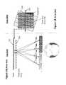
- FIG. 1Ais a frontal view of a conventional lenticular display system
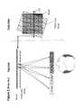
- FIG. 1Bis a top view of the conventional lenticular display system shown in FIG. 1A ;
- FIG. 2is a schematic illustration of the conventional lenticular display system shown in FIG. 1A ;
- FIG. 3is another schematic illustration of the conventional lenticular display system shown in FIG. 1A ;
- FIG. 4is a focused view of the pixel array and lens array of the conventional lenticular display system shown in FIG. 1A ;
- FIG. 5shows the effective pixels as seen by a viewer in the conventional lenticular display system shown in FIG. 1A ;
- FIG. 6illustrates the effective pixels seen as a function of viewing angle and the intensity variations of subpixel sets associated with each view in the conventional lenticular display system shown in FIG. 1A ;
- FIG. 7shows a ‘Bayer’ subpixel arrangement used in conventional capture systems
- FIG. 8shows a first subpixel arrangement for an autostereoscopic display system according to the present disclosure
- FIG. 9illustrates a second subpixel arrangement for an autostereoscopic display system according to the present disclosure
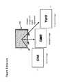
- FIG. 10is a schematic illustration of an oblique pixel according to the present disclosure.
- FIG. 11illustrates another embodiment of oblique pixels according to the present disclosure
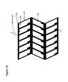
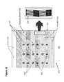
- FIG. 12shows an array of oblique pixels according to the present disclosure
- FIG. 13illustrates a preferred embodiment of the autostereoscopic display system of the present disclosure
- FIG. 14illustrates a second embodiment of the autostereoscopic display system of the present disclosure
- FIG. 15Ashows a third embodiment of the autostereoscopic display system of the present disclosure
- FIG. 15Bshows a fourth embodiment of the autostereoscopic display system of the present disclosure
- FIG. 16Ashows a fifth embodiment of the autostereoscopic display system of the present disclosure
- FIG. 16Bshows a sixth embodiment of the autostereoscopic display system of the present disclosure
- FIG. 16Cshows a seventh embodiment of the autostereoscopic display system of the present disclosure
- FIG. 17shows an exemplary embodiment of oblique pixels according to the present disclosure
- FIG. 18shows an exemplary embodiment of the autostereoscopic display system of the present disclosure.
- FIG. 19illustrates another exemplary embodiment of the autostereoscopic display system of the present disclosure.
- the present disclosureprovides autostereoscopic display systems for producing high quality images despite the constraints on pixel density in the currently available technology. More specifically, the present disclosure includes embodiments directed to the efficient arrangement and design of the colored subpixels of a display panel to provide an increased number of views within a lenticular autostereoscopic system.
- FIG. 1Ais a frontal view of a conventional lenticular autostereoscopic display system 100 , which includes a conventional display panel 102 such as an LCD panel and a tilted cylindrical lens array 104 disposed directly in front of the panel 102 .
- the panel 102is viewed through the lenses (not shown) in the cylindrical lens array 104 .
- the lensesare operable to direct the light from pixels of the panel 102 such that only some portions of the panel 102 are seen at any given viewing angle.
- FIG. 1Bis the top view of the lenticular autostereoscopic display 100 , and it illustrates the light paths in a horizontal viewing plane that intersects the panel 102 at line 106 .
- the lenses in the lens array 104are operable to effectively image the pixels in the viewing plane. This produces viewing regions where superimposed sets of these pixel images are formed. For any given viewing plane, the viewing regions are discrete.
- FIG. 2shows that at a different viewing plane that intersects the panel 102 at line 110 , the viewing angles for the same views are altered relative to the viewing angles at the viewing plane at line 106 .
- This gradual subpixel shiftacts to merge neighbor views such that a viewer sees a gradual change in views as a function of angle.
- FIG. 3illustrates what a viewer would experience when viewing the display 100 as a function of viewing position.
- the effective pixels seen by a distant viewer at any given positioncan be determined as follows. Light passing though the center of a lens is not deflected. Color and intensity seen along the lens center line is then that of the underlying subpixels directly beneath. As shown in FIG. 4 , the viewer would observe the color and intensity of the underlying subpixels 112 that are intersected by the lens center line 114 projected onto the pixel array 122 from the viewer's perspective. The lens 120 then directs light from this intersecting region toward the viewer, effectively filling the lens 120 and creating effective pixels 116 as shown in FIG. 5 . Light emanating from pixels not intersected by this projected center line 114 is deflected away and seen at different viewing angles. The lens 120 is filled in a direction normal to its center line 114 as shown in FIG. 5 .
- FIG. 6shows how the effective pixels 116 change as a function of viewing position, and hence viewing angle. Geometry dictates the movement of the projected lens center lines 114 since the lens array 104 is tilted relative to the pixel array 122 . FIG. 6 helps to illustrate the merging of the views as a function of viewing angle. Different views appear continuous with view angle until individual lenses image subpixels that lie under an adjacent lens. Views are then reset and replicated. The region containing a complete set of continuous views is called the viewing zone, with number of views within a viewing zone being equal to the number of subpixels that lie beneath a lens in the horizontal viewing plane.
- Viewing zone sizeis determined by the focal length of the lens, but to provide stereoscopic imaging, at least two views are included in the angle subtended by the viewer's eyes.
- a desirable large viewing zoneis conventionally provided by increasing the number of subpixels beneath the lens 120 to increase the number of views. To provide for this, smaller and smaller subpixels are being fabricated, but, due to the constraints on pixel density, though a better solution would be a smarter allocation of more feasibly sized subpixels.
- FIG. 6also shows the undesirable angle-dependent display intensity for displays with idealized rectangular subpixels. These artifacts become more obvious at certain distances since they manifest themselves as periodic intensity variations or moiré fringes that move with viewing position. This can be minimized by designing the subpixel masking with autostereoscopy in mind.
- the choice of the lens tilt angle together with the pitch of the lens arrayi.e. the width of the lens in the lens array
- An undesirable result of tilting the lensesis the effective pixel as seen by the viewer is also tilted, resulting in poor text rendition.
- the present disclosureis directed to allocating subpixels efficiently by modifying the density of one set of subpixels relative to that of other sets of subpixels while providing good viewing resolution.
- the density of the green subpixelsare increased.
- the density of the green subpixelsare increased relative to the density of red and blue subpixels.
- this patternhas a basis block 200 of four subpixels containing two green subpixels 202 for every single red and blue subpixels 204 and 206 .
- Lowering resolution in the lower luminance subpixelsi.e. red and blue
- This approachhas been successful for pixel-limited capture systems and has been shown to be acceptable in displays that utilize similar patterns for lower costs.
- the design considerations for these conventional applicationsare different from the design considerations for autostereoscopic display systems.
- emphasisis placed on increasing the pixel count to provide an autostereoscopic display system with as many views as possible.
- the viewing zone of lenticular autostereoscopic displaysis dictated by the horizontal spatial resolution, and accordingly, it is desirable to have as many subpixels as possible beneath a lens in a horizontal line with a continuous color.
- the color constraintsavoids local color changes as a function of viewing angle.
- CFAcolor filter array
- a display system 300comprises colored subpixels 302 , 304 , and 306 in the underlying display light-modulating panel 308 .
- the colored subpixels 302 , 304 , and 306are arranged to provide colored stripes according to a “RGBGRGBG . . . ” pattern.
- the overlaying lenses 310provide views that have the same colored striped pattern in the vertical dimension (i.e. has same vertical resolution), but has an effective pixel pitch (i.e. the width of the individual pixels in a pixel array) equivalent to that of the lens pitch in the horizontal.
- the effective green samplingis thus on a uniform square grid whereas the red and blue sampling is decreased by a factor of two in the vertical dimension only.
- the display system 350 in FIG. 9includes colored subpixels 302 , 304 , and 306 arranged to provide continuous green stripes with alternating red and blue color regions.
- uniform square grid samplingis achieved for all colors with the red and blue grids being rotated by 45°.
- FIGS. 10-12embodiments illustrated herein address non-ideal subpixels, in which a ‘black matrix’ surround is present.
- the lensesare tilted with respect to the pixel edge to avoid spatial and angular intensity variations.
- a preferred alternativeis to use oblique underlying pixels and retain the vertical lens orientation as shown in FIG. 10 .
- the oblique subpixel 400includes a black matrix boundary 402 , which may include address lines or other electrical components of a display panel. The address lines and the electrical components are painted black, thus providing the black color appearance.
- the oblique subpixel 400is shaped substantially like a parallelogram, having two pairs of substantially parallel sides, which form internally oblique angles.
- sides 403 and 405are substantially parallel
- sides 408 and 409are also substantially parallel.
- the shape of the subpixel 400corresponds to a rhomboid, whose pairs of parallel sides have different length.
- the long sides 403 and 405 and short sides 408 and 409have different lengths as shown in FIG. 10 .
- the side 403 of the oblique subpixel 400is aligned at a slant angle ⁇ 404 relative to an axis parallel to the lens center line 406 . Allowing that such an oblique subpixel 400 and a non-tiled lens may allow the, effective pixels (not shown) to remain horizontally- and vertically-aligned relative to the viewer, thereby allowing for good text rendition.
- the slant angle ⁇ 404is chosen to allow for low moiré fringing. It is also desirable in some embodiments to have the obtuse internal corners of the pixel 400 to be closely aligned in the vertical direction as shown in FIG. 10 , which would help to avoid severe merging between next nearest neighbor views. In general, these two design preferences compete with each other, and some embodiments may have noticeable moiré artifacts. To minimize such effects, the black matrix boundary 402 of the subpixel 400 may be modified.
- the intensity variation as a function of viewing angleis determined by the length of the intersection between the projected lens center line and the underlying subpixel apertures. Accordingly, as illustrated in FIG. 11 , it is desirable to shape the pixel 400 such that the sum of lengths 410 and 412 —the intersecting portions of the lens center line 406 —to be constant. This would allow the intensity to be independent of the horizontal location of the center line 406 . While such subpixels 400 shaped to have minimized intensity variation are desirable, manufacturing limitations and tolerances may prevent the fabrication of the most preferable pixel structures. To be more tolerant of manufacturing practices, a slightly increased slant angle ⁇ 404 can be introduced to suppress moiré effects to an acceptable level.
- FIG. 12Shown in FIG. 12 is an embodiment of a pixel array 450 comprising a plurality of oblique subpixels 400 assembled in a tessellation pattern, and the pixel array 450 includes a plurality of columns and rows.
- the subpixels 400may be any subpixels described in the present disclosure or constructed according to the principles of the present disclosure.
- the columns and rows of the pixel array 450zigzag as shown in FIG. 12 according to a “herring-bone” pattern. In other words, the slant direction of the subpixels in the pixel array 450 alternates between adjacent rows.
- the subpixels 400are aligned such that the dimensions of neighboring subpixels in the same column are symmetrical across their adjacent sides.
- the neighboring subpixels 400 in the same roware aligned such that a pair of parallel sides from each subpixel 400 are aligned along axes that are parallel to a longitudinal axis defined by a row of the pixel array 450 .
- FIG. 13is a perspective view of an autostereoscopic display system 500 .
- the display system 500comprises a non-titled, cylindrical lens array 502 disposed light paths of the subpixels 505 of a light-modulating display panel 504 .
- Display subpixels 506 of the panel 504are grouped in colored blocks located at the focal distance beneath the lenses 503 of the lens array 502 , and each block has a width that is substantial the same as the width of the lenses in the lens array 502 .
- the lens sampling of the display system 500provides effective pixels of a size and color of the underlying groups that remain substantially unchanged as a function of viewing angle.
- FIG. 13shows a plurality of green effective pixels 510 formed by continuous green pixels 508 .
- the aspect ratio of the effective colored pixels 510is 2:1.
- the aspect ratio of the effective colored pixelscan be varied to satisfy the various viewing performance of the display system 500 .
- the effective views of the display system 500comprise green effective pixels 510 that form a square sampling array.
- the effective viewsfurther comprise red and blue effective pixels 512 and 514 that form two diagonal sampling red and blue arrays, which are interspersed between the square green sampling array. It is to be appreciated that in other embodiments, the effective pixels of each color can form sampling arrays of varies geometry, such rectangular or herring-bone arrays.
- the resolution provided by the green arrayis greater than that of the blue and red arrays for all viewing angles other than angles close to zero, where they are near equivalent. This provides for good text rendition.
- the continuous horizontal green pixels 508maximize the luminance sampling in the horizontal dimension, thereby providing an increased number of independent views. Furthermore, continuous colored subpixels helps lower fabrication costs associated with high resolution color filter arrays.
- the underlying subpixels 506 of the display panel 504are oblique and tiled according to the ‘herring-bone’ pattern as discussed with respect to FIG. 12 . Such an arrangement of the subpixels 506 allows for minimizing issues associated with non-standard connections to the address lines. Masking for the panel 504 would preferably be designed to minimize angular and/or spatial intensity variations within manufacturing constraints. In some embodiments, the slant angles are between
- px and pyare the widths of the sides of the underlying subpixels 506 in the horizontal and vertical directions, respectively.
- the value of px and pyare determined by the desired viewing performance. In some embodiments, px is chosen to be half the minimum resolution of the eye at a typical viewing distance, and py is chosen to be the minimum possible given the constrains of manufacture and aperture ratio, the latter being traded with optical efficiency. The smaller py, the more independent views there are which can be used to increase left to right eye disparity (i.e. more depth) or increase the viewing zone.
- the lens size(which determines the pixel width) is preferably close to the resolution of the eye, i.e. subtend an angle of ⁇ 2°. This puts a preferred upper limit on the lens pitch lp of ⁇ 1 mm.
- the eyes' subtend ⁇ 2° angle with respect to the displaysuggests a preferred maximum angle per view of ⁇ 1°.
- 30 viewsare preferred, making the physical pitch of the subpixels ⁇ 30 ⁇ m which is possible with current technology. Expected future improvement should allow greater resolutions with corresponding enlarged viewing zones and view densities consistent with 3D HDTV.
- FIG. 13is not specific to any one color separated display technology, although the masking approaches considered are mostly applicable to LCDs. It is to be appreciated that the principles disclosed herein may be applied to other display technologies, including organic light emitting diode (OLED), plasma (PDP), Field emission (FED), etc.
- OLEDorganic light emitting diode
- PDPplasma
- FEDField emission
- a display system 600is illustrated in FIG. 14 , and in this embodiment, the subpixels 506 are arranged to form green, blue, and red effective pixels 602 , 604 , and 606 that implement the ‘Bayer’ color arrangement.
- the effective pixels 602 , 604 , and 606 of the display system 600may also be arranged in patterns similar to those shown in FIGS. 15A and B. In these embodiments, continuous color stripes of green effective pixels 602 provide a uniform square green sampling array, but the red and blue sampling arrays formed by red and blue effective pixels 606 and 604 are reduced either in vertical or horizontal dimensions.
- FIG. 16shows example color patterns that include white effective pixels 520 , which have been proposed by Kodak for digital camera sensors.
- Another embodimentmay include horizontal arrays of subpixels below color filter arrays with aligned overlying lenses.
- Another embodiment of the present disclosuremay be directed to using any of the above discussed color patterns and oblique pixels while employing a another masking scheme shown in FIG. 17 .
- the oblique pixels 700 designed according to the masking scheme of FIG. 17allow the intensity as a function of viewing angle to remain constant, because the intersection of any projected center line 406 of the overlying lens and the clear aperture the pixels 700 remains constant.
- Other embodimentsmay include oblique pixels with a fixed masking pattern. In this case, the slant angle of the pixels could be increased slightly to minimize moiré fringing.
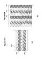
- Yet another embodimentmay include a light-modulating display panel 800 having oblique pixels 506 arranged in straight, though tilted columns, as shown in FIG. 18 .
- the color sampling arraysare staggered.
- Another approachwould be to retain the non-oblique pixels and tilt the lenses as used in conventional autostereoscopic lenticular systems.
- the advantages of such a display systeminclude the convenience of rectangular pixel arrays and the very low angle required to merge adjacent views. Such a low angle might not compromise text sufficiently to warrant concern.
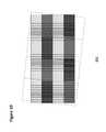
- An example of this embodimentis the display system 900 shown in FIG. 19 .
Landscapes
- Engineering & Computer Science (AREA)
- Multimedia (AREA)
- Signal Processing (AREA)
- Physics & Mathematics (AREA)
- Optics & Photonics (AREA)
- Testing, Inspecting, Measuring Of Stereoscopic Televisions And Televisions (AREA)
Abstract
Description
where px and py are the widths of the sides of the
Claims (16)
Priority Applications (1)
| Application Number | Priority Date | Filing Date | Title |
|---|---|---|---|
| US12/541,895US8542432B2 (en) | 2008-08-14 | 2009-08-14 | Autostereoscopic display system with efficient pixel layout |
Applications Claiming Priority (2)
| Application Number | Priority Date | Filing Date | Title |
|---|---|---|---|
| US8900908P | 2008-08-14 | 2008-08-14 | |
| US12/541,895US8542432B2 (en) | 2008-08-14 | 2009-08-14 | Autostereoscopic display system with efficient pixel layout |
Publications (2)
| Publication Number | Publication Date |
|---|---|
| US20100039698A1 US20100039698A1 (en) | 2010-02-18 |
| US8542432B2true US8542432B2 (en) | 2013-09-24 |
Family
ID=41669349
Family Applications (1)
| Application Number | Title | Priority Date | Filing Date |
|---|---|---|---|
| US12/541,895Active2029-10-31US8542432B2 (en) | 2008-08-14 | 2009-08-14 | Autostereoscopic display system with efficient pixel layout |
Country Status (2)
| Country | Link |
|---|---|
| US (1) | US8542432B2 (en) |
| WO (1) | WO2010019923A1 (en) |
Cited By (2)
| Publication number | Priority date | Publication date | Assignee | Title |
|---|---|---|---|---|
| US20150237331A1 (en)* | 2014-02-20 | 2015-08-20 | Au Optronics Corp. | 3d image adjustment method and 3d display apparatus using the same |
| US20190137771A1 (en)* | 2016-04-28 | 2019-05-09 | Hewlett-Packard Development Company, L.P. | Digital display devices |
Families Citing this family (20)
| Publication number | Priority date | Publication date | Assignee | Title |
|---|---|---|---|---|
| CN102725681B (en)* | 2010-01-29 | 2015-01-28 | 夏普株式会社 | Liquid crystal display device |
| DE102010018083B4 (en)* | 2010-04-23 | 2013-05-08 | Tridelity Ag | Simultaneous reproduction of a plurality of images by means of a two-dimensional image representation matrix |
| KR20120010404A (en)* | 2010-07-26 | 2012-02-03 | 삼성전자주식회사 | Multiview Display System and Method Using Color-Maintaining Selective Subpixel Rendering |
| BR112014003829A2 (en) | 2011-08-24 | 2017-03-14 | Koninklijke Philips Nv | auto stereoscopic display device, method for displaying auto stereoscopic images and method of manufacturing a auto stereoscopic display device |
| US8937646B1 (en)* | 2011-10-05 | 2015-01-20 | Amazon Technologies, Inc. | Stereo imaging using disparate imaging devices |
| US20130127861A1 (en)* | 2011-11-18 | 2013-05-23 | Jacques Gollier | Display apparatuses and methods for simulating an autostereoscopic display device |
| KR20130055997A (en) | 2011-11-21 | 2013-05-29 | 삼성디스플레이 주식회사 | 3-dimensional image display device |
| FR2995713B1 (en)* | 2012-09-14 | 2015-07-17 | Alioscopy | DISPLAY SCREEN, ESPECIALLY FOR AUTOSTEREOSCOPY. |
| CN103777398B (en)* | 2012-10-23 | 2016-12-21 | 上海天马微电子有限公司 | Stereoscopic image display device |
| WO2014076587A1 (en) | 2012-11-16 | 2014-05-22 | Koninklijke Philips N.V. | Autostereoscopic display device |
| WO2014173853A1 (en)* | 2013-04-25 | 2014-10-30 | Koninklijke Philips N.V. | Auto-stereoscopic display device with a lenticular sheet slanted with respect to the column of colour sub-pixels |
| BR102013013559A2 (en)* | 2013-05-31 | 2015-07-14 | Roberto Massaru Amemiya | Three-dimensional ray-camcorder and real-image television produced in front of and behind the television surface; parallel ray filter devices; paired liquid crystals or optical cell movement or parallel ray filter with movable lens assembly including multifocal flexible lenses; processes for obtaining these devices |
| BR102013021422A2 (en)* | 2013-08-22 | 2015-11-17 | Roberto Massaru Amemiya | image processing apparatus carried out between real image camcorder and real image television through movable windows; introduction and control of three-dimensional image in the field of real image projection; process for obtaining that device |
| BR102013021423B1 (en)* | 2013-08-22 | 2021-01-19 | Roberto Massaru Amemiya | camcorder and television that produce real images using parallel ray filter devices formed by multiple paired liquid crystals; electrical pulse processor with image parameters to obtain real image projection and distance control in front of and behind the television surface; introduction and control of three-dimensional image in the projection field of the real image; processes for obtaining these devices |
| CN105849623B (en) | 2013-12-20 | 2019-09-10 | 皇家飞利浦有限公司 | Auto-stereoscopic display device |
| CN104978920B (en) | 2015-07-24 | 2018-10-16 | 京东方科技集团股份有限公司 | Pel array, display device and its display methods |
| CN105304678B (en)* | 2015-09-25 | 2018-11-16 | 上海和辉光电有限公司 | The pixel arrangement structure and mask plate of organic LED display panel |
| KR101835060B1 (en)* | 2016-06-30 | 2018-03-07 | 엘지디스플레이 주식회사 | Autostereoscopic 3-Dimensional Display |
| KR101880751B1 (en)* | 2017-03-21 | 2018-07-20 | 주식회사 모픽 | Method for reducing error by allignment of lenticular lens and user terminal for displaying glass free stereoscopic image and the user terminal of perporming the method |
| DE102017117540A1 (en)* | 2017-08-02 | 2019-02-07 | Osram Opto Semiconductors Gmbh | Light-emitting semiconductor chip and display device |
Citations (47)
| Publication number | Priority date | Publication date | Assignee | Title |
|---|---|---|---|---|
| US1128979A (en) | 1912-06-01 | 1915-02-16 | Walter Hess | Stereoscopic picture. |
| US1970311A (en) | 1931-02-14 | 1934-08-14 | Bell Telephone Labor Inc | Projection of images for viewing in stereoscopic relief |
| US3409351A (en) | 1966-02-07 | 1968-11-05 | Douglas F. Winnek | Composite stereography |
| US4542958A (en) | 1983-01-13 | 1985-09-24 | Vasco, Ltd. | Variable aspect display |
| US4804253A (en) | 1986-05-15 | 1989-02-14 | General Electric Company | Lenticular filter for display devices |
| US4807978A (en) | 1987-09-10 | 1989-02-28 | Hughes Aircraft Company | Color display device and method using holographic lenses |
| US4829365A (en) | 1986-03-07 | 1989-05-09 | Dimension Technologies, Inc. | Autostereoscopic display with illuminating lines, light valve and mask |
| US5278608A (en) | 1992-05-19 | 1994-01-11 | Eastman Kodak Company | Electronically printed depth photography system with improved viewing range |
| US5349419A (en) | 1992-04-15 | 1994-09-20 | Fuji Photo Film Co., Ltd. | Method and apparatus for recording stereoscopic images |
| US5466926A (en) | 1992-01-27 | 1995-11-14 | Kabushiki Kaisha Toshiba | Colored microlens array and method of manufacturing same |
| US5510831A (en) | 1994-02-10 | 1996-04-23 | Vision Iii Imaging, Inc. | Autostereoscopic imaging apparatus and method using suit scanning of parallax images |
| US5581402A (en) | 1993-11-22 | 1996-12-03 | Eastman Kodak Company | Method for producing an improved stereoscopic picture and stereoscopic picture obtained according to this method |
| US5588526A (en) | 1994-04-01 | 1996-12-31 | Insight, Inc. | Flat box system with multiple view optics |
| US5697006A (en) | 1992-02-06 | 1997-12-09 | Fuji Photo Film Co., Ltd. | Method and apparatus for recording stereoscopic images and lenticular recording material used therefor |
| US5808792A (en) | 1995-02-09 | 1998-09-15 | Sharp Kabushiki Kaisha | Autostereoscopic display and method of controlling an autostereoscopic display |
| US5875055A (en) | 1995-06-29 | 1999-02-23 | Canon Kabushiki Kaisha | Stereoscopic image display method and stereoscopic image display apparatus using the same |
| US5933276A (en) | 1994-04-13 | 1999-08-03 | Board Of Trustees, University Of Arkansas, N.A. | Aberration-free directional image window sheet |
| US6008484A (en) | 1996-09-27 | 1999-12-28 | Sharp Kabushiki Kaisha | Observer tracking directional display and observer tracking illumination system |
| US6023315A (en) | 1995-07-04 | 2000-02-08 | Sharp Kabushiki Kaisha | Spatial light modulator and directional display |
| US6055013A (en) | 1997-02-04 | 2000-04-25 | Sharp Kabushiki Kaisha | Autostereoscopic display |
| US6064424A (en) | 1996-02-23 | 2000-05-16 | U.S. Philips Corporation | Autostereoscopic display apparatus |
| US6094216A (en) | 1995-05-22 | 2000-07-25 | Canon Kabushiki Kaisha | Stereoscopic image display method, and stereoscopic image display apparatus using the method |
| US6118584A (en) | 1995-07-05 | 2000-09-12 | U.S. Philips Corporation | Autostereoscopic display apparatus |
| US6224214B1 (en) | 1997-03-27 | 2001-05-01 | Litton Systems, Inc. | Autostereo projection system |
| US6302541B1 (en) | 1998-06-20 | 2001-10-16 | Christoph Grossmann | Method and device for autostereoscopy |
| US20010050686A1 (en) | 2000-02-15 | 2001-12-13 | U.S. Philips Corporation | Autostereoscopic display driver |
| US6373637B1 (en) | 2000-09-13 | 2002-04-16 | Eastman Kodak Company | Diagonal lenticular image system |
| US6456340B1 (en) | 1998-08-12 | 2002-09-24 | Pixonics, Llc | Apparatus and method for performing image transforms in a digital display system |
| US6476850B1 (en) | 1998-10-09 | 2002-11-05 | Kenneth Erbey | Apparatus for the generation of a stereoscopic display |
| US20030016444A1 (en)* | 2001-07-13 | 2003-01-23 | Brown Daniel M. | Autostereoscopic display with rotated microlens and method of displaying multidimensional images, especially color images |
| US20040046709A1 (en) | 2002-09-05 | 2004-03-11 | Kazutora Yoshino | 3 Dimensional image projector and holodeck |
| US6736512B2 (en) | 2000-02-21 | 2004-05-18 | Sony International (Europe) Gmbh | Pixel element for a three-dimensional screen |
| US20040135741A1 (en) | 2002-10-31 | 2004-07-15 | Pioneer Corporation | Apparatus and method for displaying three-dimensional image |
| US6801243B1 (en) | 1997-07-23 | 2004-10-05 | Koninklijke Philips Electronics N.V. | Lenticular screen adaptor |
| US6816158B1 (en) | 1998-10-30 | 2004-11-09 | Lemelson Jerome H | Three-dimensional display system |
| US20040263969A1 (en) | 2002-11-25 | 2004-12-30 | Lenny Lipton | Lenticular antireflection display |
| WO2005006775A1 (en) | 2003-07-10 | 2005-01-20 | Ocuity Limited | Colour pixel configuration for an autostereoscopic display |
| US6847354B2 (en) | 2000-03-23 | 2005-01-25 | The United States Of America As Represented By The Administrator Of The National Aeronautics And Space Administration | Three dimensional interactive display |
| US6859240B1 (en) | 2000-01-27 | 2005-02-22 | Mems Optical Inc. | Autostereoscopic display |
| US7091931B2 (en) | 2001-08-17 | 2006-08-15 | Geo-Rae Co., Ltd. | Method and system of stereoscopic image display for guiding a viewer's eye motion using a three-dimensional mouse |
| US20060284974A1 (en) | 2005-04-08 | 2006-12-21 | Lenny Lipton | Autostereoscopic display with planar pass-through |
| US20070035829A1 (en) | 2003-09-30 | 2007-02-15 | Ocuity Limited | Directional display apparatus |
| US20070109401A1 (en) | 2005-11-14 | 2007-05-17 | Real D | Monitor with integral interdigitation |
| US7239293B2 (en) | 1998-01-21 | 2007-07-03 | New York University | Autostereoscopic display |
| US20080079662A1 (en) | 2006-10-03 | 2008-04-03 | Kabushiki Kaisha Toshiba. | Stereoscopic display apparatus |
| US7365908B2 (en) | 2001-11-08 | 2008-04-29 | Eugene Dolgoff | Tiling of panels for multiple-image displays |
| US7375886B2 (en) | 2004-04-19 | 2008-05-20 | Stereographics Corporation | Method and apparatus for optimizing the viewing distance of a lenticular stereogram |
- 2009
- 2009-08-14USUS12/541,895patent/US8542432B2/enactiveActive
- 2009-08-14WOPCT/US2009/053951patent/WO2010019923A1/enactiveApplication Filing
Patent Citations (50)
| Publication number | Priority date | Publication date | Assignee | Title |
|---|---|---|---|---|
| US1128979A (en) | 1912-06-01 | 1915-02-16 | Walter Hess | Stereoscopic picture. |
| US1970311A (en) | 1931-02-14 | 1934-08-14 | Bell Telephone Labor Inc | Projection of images for viewing in stereoscopic relief |
| US3409351A (en) | 1966-02-07 | 1968-11-05 | Douglas F. Winnek | Composite stereography |
| US4542958A (en) | 1983-01-13 | 1985-09-24 | Vasco, Ltd. | Variable aspect display |
| US4829365A (en) | 1986-03-07 | 1989-05-09 | Dimension Technologies, Inc. | Autostereoscopic display with illuminating lines, light valve and mask |
| US4804253A (en) | 1986-05-15 | 1989-02-14 | General Electric Company | Lenticular filter for display devices |
| US4807978A (en) | 1987-09-10 | 1989-02-28 | Hughes Aircraft Company | Color display device and method using holographic lenses |
| US5466926A (en) | 1992-01-27 | 1995-11-14 | Kabushiki Kaisha Toshiba | Colored microlens array and method of manufacturing same |
| US5850580A (en) | 1992-02-06 | 1998-12-15 | Fuji Photo Film Co., Ltd. | Method and apparatus for recording stereoscopic images and lenticular recording material used thereof |
| US5697006A (en) | 1992-02-06 | 1997-12-09 | Fuji Photo Film Co., Ltd. | Method and apparatus for recording stereoscopic images and lenticular recording material used therefor |
| US5349419A (en) | 1992-04-15 | 1994-09-20 | Fuji Photo Film Co., Ltd. | Method and apparatus for recording stereoscopic images |
| US5278608A (en) | 1992-05-19 | 1994-01-11 | Eastman Kodak Company | Electronically printed depth photography system with improved viewing range |
| US5581402A (en) | 1993-11-22 | 1996-12-03 | Eastman Kodak Company | Method for producing an improved stereoscopic picture and stereoscopic picture obtained according to this method |
| US5510831A (en) | 1994-02-10 | 1996-04-23 | Vision Iii Imaging, Inc. | Autostereoscopic imaging apparatus and method using suit scanning of parallax images |
| US5588526A (en) | 1994-04-01 | 1996-12-31 | Insight, Inc. | Flat box system with multiple view optics |
| US5933276A (en) | 1994-04-13 | 1999-08-03 | Board Of Trustees, University Of Arkansas, N.A. | Aberration-free directional image window sheet |
| US5808792A (en) | 1995-02-09 | 1998-09-15 | Sharp Kabushiki Kaisha | Autostereoscopic display and method of controlling an autostereoscopic display |
| US6094216A (en) | 1995-05-22 | 2000-07-25 | Canon Kabushiki Kaisha | Stereoscopic image display method, and stereoscopic image display apparatus using the method |
| US5875055A (en) | 1995-06-29 | 1999-02-23 | Canon Kabushiki Kaisha | Stereoscopic image display method and stereoscopic image display apparatus using the same |
| US6023315A (en) | 1995-07-04 | 2000-02-08 | Sharp Kabushiki Kaisha | Spatial light modulator and directional display |
| US6118584A (en) | 1995-07-05 | 2000-09-12 | U.S. Philips Corporation | Autostereoscopic display apparatus |
| US6064424A (en) | 1996-02-23 | 2000-05-16 | U.S. Philips Corporation | Autostereoscopic display apparatus |
| US6008484A (en) | 1996-09-27 | 1999-12-28 | Sharp Kabushiki Kaisha | Observer tracking directional display and observer tracking illumination system |
| US6055013A (en) | 1997-02-04 | 2000-04-25 | Sharp Kabushiki Kaisha | Autostereoscopic display |
| US6224214B1 (en) | 1997-03-27 | 2001-05-01 | Litton Systems, Inc. | Autostereo projection system |
| US6481849B2 (en) | 1997-03-27 | 2002-11-19 | .Litton Systems, Inc. | Autostereo projection system |
| US6801243B1 (en) | 1997-07-23 | 2004-10-05 | Koninklijke Philips Electronics N.V. | Lenticular screen adaptor |
| US7239293B2 (en) | 1998-01-21 | 2007-07-03 | New York University | Autostereoscopic display |
| US6302541B1 (en) | 1998-06-20 | 2001-10-16 | Christoph Grossmann | Method and device for autostereoscopy |
| US6456340B1 (en) | 1998-08-12 | 2002-09-24 | Pixonics, Llc | Apparatus and method for performing image transforms in a digital display system |
| US6476850B1 (en) | 1998-10-09 | 2002-11-05 | Kenneth Erbey | Apparatus for the generation of a stereoscopic display |
| US6816158B1 (en) | 1998-10-30 | 2004-11-09 | Lemelson Jerome H | Three-dimensional display system |
| US6859240B1 (en) | 2000-01-27 | 2005-02-22 | Mems Optical Inc. | Autostereoscopic display |
| US20010050686A1 (en) | 2000-02-15 | 2001-12-13 | U.S. Philips Corporation | Autostereoscopic display driver |
| US6736512B2 (en) | 2000-02-21 | 2004-05-18 | Sony International (Europe) Gmbh | Pixel element for a three-dimensional screen |
| US6847354B2 (en) | 2000-03-23 | 2005-01-25 | The United States Of America As Represented By The Administrator Of The National Aeronautics And Space Administration | Three dimensional interactive display |
| US6373637B1 (en) | 2000-09-13 | 2002-04-16 | Eastman Kodak Company | Diagonal lenticular image system |
| US6825985B2 (en) | 2001-07-13 | 2004-11-30 | Mems Optical, Inc. | Autostereoscopic display with rotated microlens and method of displaying multidimensional images, especially color images |
| US20030016444A1 (en)* | 2001-07-13 | 2003-01-23 | Brown Daniel M. | Autostereoscopic display with rotated microlens and method of displaying multidimensional images, especially color images |
| US7091931B2 (en) | 2001-08-17 | 2006-08-15 | Geo-Rae Co., Ltd. | Method and system of stereoscopic image display for guiding a viewer's eye motion using a three-dimensional mouse |
| US7365908B2 (en) | 2001-11-08 | 2008-04-29 | Eugene Dolgoff | Tiling of panels for multiple-image displays |
| US20040046709A1 (en) | 2002-09-05 | 2004-03-11 | Kazutora Yoshino | 3 Dimensional image projector and holodeck |
| US20040135741A1 (en) | 2002-10-31 | 2004-07-15 | Pioneer Corporation | Apparatus and method for displaying three-dimensional image |
| US20040263969A1 (en) | 2002-11-25 | 2004-12-30 | Lenny Lipton | Lenticular antireflection display |
| WO2005006775A1 (en) | 2003-07-10 | 2005-01-20 | Ocuity Limited | Colour pixel configuration for an autostereoscopic display |
| US20070035829A1 (en) | 2003-09-30 | 2007-02-15 | Ocuity Limited | Directional display apparatus |
| US7375886B2 (en) | 2004-04-19 | 2008-05-20 | Stereographics Corporation | Method and apparatus for optimizing the viewing distance of a lenticular stereogram |
| US20060284974A1 (en) | 2005-04-08 | 2006-12-21 | Lenny Lipton | Autostereoscopic display with planar pass-through |
| US20070109401A1 (en) | 2005-11-14 | 2007-05-17 | Real D | Monitor with integral interdigitation |
| US20080079662A1 (en) | 2006-10-03 | 2008-04-03 | Kabushiki Kaisha Toshiba. | Stereoscopic display apparatus |
Non-Patent Citations (1)
| Title |
|---|
| International Search Report and Written Opinion for PCT/US2009/053951 mailed Oct. 6, 2009. |
Cited By (4)
| Publication number | Priority date | Publication date | Assignee | Title |
|---|---|---|---|---|
| US20150237331A1 (en)* | 2014-02-20 | 2015-08-20 | Au Optronics Corp. | 3d image adjustment method and 3d display apparatus using the same |
| US9749616B2 (en)* | 2014-02-20 | 2017-08-29 | Au Optronics Corp. | 3D image adjustment method and 3D display apparatus using the same |
| US20190137771A1 (en)* | 2016-04-28 | 2019-05-09 | Hewlett-Packard Development Company, L.P. | Digital display devices |
| US10663755B2 (en)* | 2016-04-28 | 2020-05-26 | Hewlett-Packard Development Company, L.P. | Digital displays devices |
Also Published As
| Publication number | Publication date |
|---|---|
| US20100039698A1 (en) | 2010-02-18 |
| WO2010019923A1 (en) | 2010-02-18 |
Similar Documents
| Publication | Publication Date | Title |
|---|---|---|
| US8542432B2 (en) | Autostereoscopic display system with efficient pixel layout | |
| KR101912255B1 (en) | Light output panel and device having the same | |
| JP5301591B2 (en) | Multi view display | |
| KR102308388B1 (en) | Autostereoscopic display device | |
| CN100516976C (en) | Stereoscopic display device and image display method | |
| JP5899389B1 (en) | Autostereoscopic display device | |
| KR100711168B1 (en) | Stereoscopic image display apparatus and stereoscopic image display method | |
| TWI514005B (en) | Non-glasses type stereoscopic image display device | |
| US20100265577A1 (en) | Stereoscopic image display device | |
| WO2013042332A1 (en) | Video display method, video display panel, and video display apparatus | |
| CN101263722A (en) | Autostereoscopic display device and filter therefor | |
| CN1534328A (en) | Parallax Barriers and Multi-View Displays | |
| JP2005309374A (en) | 3D display | |
| JP2009139947A (en) | 3D image display apparatus and driving method thereof | |
| CN102246528B (en) | Lenticular display system with offset color filter array | |
| US8743113B2 (en) | Stereoscopic image display apparatus | |
| WO2011058967A1 (en) | Parallax barrier filter | |
| US10511831B2 (en) | Display device and method for displaying | |
| KR20130053103A (en) | Display panel and display apparatus having the same | |
| US20150043066A1 (en) | Three-dimensional television display | |
| JP2005234198A (en) | Stereoscopic image display device | |
| CN1913648A (en) | Image display device and stereoscopic image generating structure used in the image display device | |
| CN105629489A (en) | 3D display screen and 3D display device | |
| JP5115840B2 (en) | 3D display device | |
| WO2020135360A1 (en) | Autostereoscopic display |
Legal Events
| Date | Code | Title | Description |
|---|---|---|---|
| AS | Assignment | Owner name:REAL D,CALIFORNIA Free format text:ASSIGNMENT OF ASSIGNORS INTEREST;ASSIGNORS:ROBINSON, MICHAEL G.;MCKNIGHT, DOUGLAS J.;SIGNING DATES FROM 20090908 TO 20090909;REEL/FRAME:023244/0289 Owner name:REAL D, CALIFORNIA Free format text:ASSIGNMENT OF ASSIGNORS INTEREST;ASSIGNORS:ROBINSON, MICHAEL G.;MCKNIGHT, DOUGLAS J.;SIGNING DATES FROM 20090908 TO 20090909;REEL/FRAME:023244/0289 | |
| AS | Assignment | Owner name:REALD INC.,CALIFORNIA Free format text:MERGER;ASSIGNOR:REAL D;REEL/FRAME:024294/0658 Effective date:20100408 Owner name:REALD INC., CALIFORNIA Free format text:MERGER;ASSIGNOR:REAL D;REEL/FRAME:024294/0658 Effective date:20100408 | |
| AS | Assignment | Owner name:CITY NATIONAL BANK, AS ADMINISTRATIVE AGENT, CALIF Free format text:PATENT SECURITY AGREEMENT;ASSIGNOR:REALD, INC.;REEL/FRAME:028146/0006 Effective date:20120419 | |
| STCF | Information on status: patent grant | Free format text:PATENTED CASE | |
| AS | Assignment | Owner name:REALD INC., CALIFORNIA Free format text:RELEASE FROM PATENT SECURITY AGREEMENTS AT REEL/FRAME NO. 28146/0006;ASSIGNOR:CITY NATIONAL BANK;REEL/FRAME:038216/0436 Effective date:20160322 | |
| AS | Assignment | Owner name:HIGHBRIDGE PRINCIPAL STRATEGIES, LLC, NEW YORK Free format text:SECURITY INTEREST;ASSIGNORS:REALD INC.;STEREOGRAPHICS CORPORATION;COLORLINK INC.;AND OTHERS;REEL/FRAME:038243/0526 Effective date:20160322 | |
| FPAY | Fee payment | Year of fee payment:4 | |
| AS | Assignment | Owner name:JEFFERIES FINANCE LLC, AS COLLATERAL AGENT, NEW YORK Free format text:SECURITY INTEREST;ASSIGNORS:REALD INC.;RHOMBUS INTERMEDIATE HOLDINGS, LP;REALD HOLDINGS, INC;AND OTHERS;REEL/FRAME:047723/0767 Effective date:20181130 Owner name:JEFFERIES FINANCE LLC, AS COLLATERAL AGENT, NEW YO Free format text:SECURITY INTEREST;ASSIGNORS:REALD INC.;RHOMBUS INTERMEDIATE HOLDINGS, LP;REALD HOLDINGS, INC;AND OTHERS;REEL/FRAME:047723/0767 Effective date:20181130 | |
| AS | Assignment | Owner name:JEFFERIES FINANCE LLC, AS COLLATERAL AGENT, NEW YORK Free format text:SECURITY INTEREST;ASSIGNORS:REALD INC.;RHOMBUS INTERMEDIATE HOLDINGS, LP;REALD HOLDINGS, INC;AND OTHERS;REEL/FRAME:047740/0085 Effective date:20181130 Owner name:JEFFERIES FINANCE LLC, AS COLLATERAL AGENT, NEW YO Free format text:SECURITY INTEREST;ASSIGNORS:REALD INC.;RHOMBUS INTERMEDIATE HOLDINGS, LP;REALD HOLDINGS, INC;AND OTHERS;REEL/FRAME:047740/0085 Effective date:20181130 Owner name:REALD DDMG ACQUISITION, LLC, CALIFORNIA Free format text:RELEASE BY SECURED PARTY;ASSIGNOR:HPS INVESTMENT PARTNERS, LLC, AS COLLATERAL AGENT;REEL/FRAME:047741/0621 Effective date:20181130 Owner name:REALD INC., CALIFORNIA Free format text:RELEASE BY SECURED PARTY;ASSIGNOR:HPS INVESTMENT PARTNERS, LLC, AS COLLATERAL AGENT;REEL/FRAME:047741/0621 Effective date:20181130 Owner name:COLORLINK, INC., CALIFORNIA Free format text:RELEASE BY SECURED PARTY;ASSIGNOR:HPS INVESTMENT PARTNERS, LLC, AS COLLATERAL AGENT;REEL/FRAME:047741/0621 Effective date:20181130 Owner name:STEREOGRAPHICS CORPORATION, CALIFORNIA Free format text:RELEASE BY SECURED PARTY;ASSIGNOR:HPS INVESTMENT PARTNERS, LLC, AS COLLATERAL AGENT;REEL/FRAME:047741/0621 Effective date:20181130 | |
| AS | Assignment | Owner name:HPS INVESTMENT PARTNERS, LLC, AS THE SUCCESSOR-IN-INTEREST, NEW YORK Free format text:SECURITY INTEREST;ASSIGNOR:JEFFERIES FINANCE LLC, AS COLLATERAL AGENT;REEL/FRAME:052622/0104 Effective date:20200506 Owner name:CORTLAND CAPITAL MARKET SERVICES LLC, AS THE SUCCESSOR COLLATERAL AGENT, ILLINOIS Free format text:ASSIGNMENT OF SECURITY INTEREST IN COLLATERAL;ASSIGNOR:JEFFERIES FINANCE LLC, AS COLLATERAL AGENT;REEL/FRAME:052623/0086 Effective date:20200506 | |
| AS | Assignment | Owner name:REALD SPARK, LLC, CALIFORNIA Free format text:RELEASE OF SECURITY INTEREST RECORDED AT REEL/FRAME 047740/0085;ASSIGNOR:CORTLAND CAPITAL MARKET SERVICES, LLC;REEL/FRAME:054593/0247 Effective date:20201120 Owner name:RHOMBUS INTERMEDIATE HOLDINGS, LP, CALIFORNIA Free format text:RELEASE OF SECURITY INTEREST RECORDED AT REEL/FRAME 047740/0085;ASSIGNOR:CORTLAND CAPITAL MARKET SERVICES, LLC;REEL/FRAME:054593/0247 Effective date:20201120 Owner name:COLORLINK, INC., CALIFORNIA Free format text:RELEASE OF SECURITY INTEREST RECORDED AT REEL/FRAME 047740/0085;ASSIGNOR:CORTLAND CAPITAL MARKET SERVICES, LLC;REEL/FRAME:054593/0247 Effective date:20201120 Owner name:REALD DDMG ACQUISITION, LLC, CALIFORNIA Free format text:RELEASE OF SECURITY INTEREST RECORDED AT REEL/FRAME 047740/0085;ASSIGNOR:CORTLAND CAPITAL MARKET SERVICES, LLC;REEL/FRAME:054593/0247 Effective date:20201120 Owner name:REALD INC., CALIFORNIA Free format text:RELEASE OF SECURITY INTEREST RECORDED AT REEL/FRAME 047740/0085;ASSIGNOR:CORTLAND CAPITAL MARKET SERVICES, LLC;REEL/FRAME:054593/0247 Effective date:20201120 | |
| MAFP | Maintenance fee payment | Free format text:PAYMENT OF MAINTENANCE FEE, 8TH YR, SMALL ENTITY (ORIGINAL EVENT CODE: M2552); ENTITY STATUS OF PATENT OWNER: SMALL ENTITY Year of fee payment:8 | |
| MAFP | Maintenance fee payment | Free format text:PAYMENT OF MAINTENANCE FEE, 12TH YR, SMALL ENTITY (ORIGINAL EVENT CODE: M2553); ENTITY STATUS OF PATENT OWNER: SMALL ENTITY Year of fee payment:12 |