US8540763B2 - Detachable self-expanding aneurysm cover device - Google Patents
Detachable self-expanding aneurysm cover deviceDownload PDFInfo
- Publication number
- US8540763B2 US8540763B2US11/903,463US90346307AUS8540763B2US 8540763 B2US8540763 B2US 8540763B2US 90346307 AUS90346307 AUS 90346307AUS 8540763 B2US8540763 B2US 8540763B2
- Authority
- US
- United States
- Prior art keywords
- skeletal frame
- cover device
- loop portion
- longitudinal axis
- aneurysm
- Prior art date
- Legal status (The legal status is an assumption and is not a legal conclusion. Google has not performed a legal analysis and makes no representation as to the accuracy of the status listed.)
- Active, expires
Links
Images


Classifications
- A—HUMAN NECESSITIES
- A61—MEDICAL OR VETERINARY SCIENCE; HYGIENE
- A61B—DIAGNOSIS; SURGERY; IDENTIFICATION
- A61B17/00—Surgical instruments, devices or methods
- A61B17/12—Surgical instruments, devices or methods for ligaturing or otherwise compressing tubular parts of the body, e.g. blood vessels or umbilical cord
- A61B17/12022—Occluding by internal devices, e.g. balloons or releasable wires
- A61B17/12099—Occluding by internal devices, e.g. balloons or releasable wires characterised by the location of the occluder
- A61B17/12109—Occluding by internal devices, e.g. balloons or releasable wires characterised by the location of the occluder in a blood vessel
- A61B17/12113—Occluding by internal devices, e.g. balloons or releasable wires characterised by the location of the occluder in a blood vessel within an aneurysm
- A61B17/12118—Occluding by internal devices, e.g. balloons or releasable wires characterised by the location of the occluder in a blood vessel within an aneurysm for positioning in conjunction with a stent
- A—HUMAN NECESSITIES
- A61—MEDICAL OR VETERINARY SCIENCE; HYGIENE
- A61F—FILTERS IMPLANTABLE INTO BLOOD VESSELS; PROSTHESES; DEVICES PROVIDING PATENCY TO, OR PREVENTING COLLAPSING OF, TUBULAR STRUCTURES OF THE BODY, e.g. STENTS; ORTHOPAEDIC, NURSING OR CONTRACEPTIVE DEVICES; FOMENTATION; TREATMENT OR PROTECTION OF EYES OR EARS; BANDAGES, DRESSINGS OR ABSORBENT PADS; FIRST-AID KITS
- A61F2/00—Filters implantable into blood vessels; Prostheses, i.e. artificial substitutes or replacements for parts of the body; Appliances for connecting them with the body; Devices providing patency to, or preventing collapsing of, tubular structures of the body, e.g. stents
- A61F2/82—Devices providing patency to, or preventing collapsing of, tubular structures of the body, e.g. stents
- A61F2/86—Stents in a form characterised by the wire-like elements; Stents in the form characterised by a net-like or mesh-like structure
- A61F2/90—Stents in a form characterised by the wire-like elements; Stents in the form characterised by a net-like or mesh-like structure characterised by a net-like or mesh-like structure
- A61F2/91—Stents in a form characterised by the wire-like elements; Stents in the form characterised by a net-like or mesh-like structure characterised by a net-like or mesh-like structure made from perforated sheets or tubes, e.g. perforated by laser cuts or etched holes
- A—HUMAN NECESSITIES
- A61—MEDICAL OR VETERINARY SCIENCE; HYGIENE
- A61B—DIAGNOSIS; SURGERY; IDENTIFICATION
- A61B17/00—Surgical instruments, devices or methods
- A61B17/12—Surgical instruments, devices or methods for ligaturing or otherwise compressing tubular parts of the body, e.g. blood vessels or umbilical cord
- A61B17/12022—Occluding by internal devices, e.g. balloons or releasable wires
- A61B2017/1205—Introduction devices
- A—HUMAN NECESSITIES
- A61—MEDICAL OR VETERINARY SCIENCE; HYGIENE
- A61F—FILTERS IMPLANTABLE INTO BLOOD VESSELS; PROSTHESES; DEVICES PROVIDING PATENCY TO, OR PREVENTING COLLAPSING OF, TUBULAR STRUCTURES OF THE BODY, e.g. STENTS; ORTHOPAEDIC, NURSING OR CONTRACEPTIVE DEVICES; FOMENTATION; TREATMENT OR PROTECTION OF EYES OR EARS; BANDAGES, DRESSINGS OR ABSORBENT PADS; FIRST-AID KITS
- A61F2/00—Filters implantable into blood vessels; Prostheses, i.e. artificial substitutes or replacements for parts of the body; Appliances for connecting them with the body; Devices providing patency to, or preventing collapsing of, tubular structures of the body, e.g. stents
- A61F2/95—Instruments specially adapted for placement or removal of stents or stent-grafts
- A—HUMAN NECESSITIES
- A61—MEDICAL OR VETERINARY SCIENCE; HYGIENE
- A61F—FILTERS IMPLANTABLE INTO BLOOD VESSELS; PROSTHESES; DEVICES PROVIDING PATENCY TO, OR PREVENTING COLLAPSING OF, TUBULAR STRUCTURES OF THE BODY, e.g. STENTS; ORTHOPAEDIC, NURSING OR CONTRACEPTIVE DEVICES; FOMENTATION; TREATMENT OR PROTECTION OF EYES OR EARS; BANDAGES, DRESSINGS OR ABSORBENT PADS; FIRST-AID KITS
- A61F2/00—Filters implantable into blood vessels; Prostheses, i.e. artificial substitutes or replacements for parts of the body; Appliances for connecting them with the body; Devices providing patency to, or preventing collapsing of, tubular structures of the body, e.g. stents
- A61F2/82—Devices providing patency to, or preventing collapsing of, tubular structures of the body, e.g. stents
- A61F2002/823—Stents, different from stent-grafts, adapted to cover an aneurysm
- A—HUMAN NECESSITIES
- A61—MEDICAL OR VETERINARY SCIENCE; HYGIENE
- A61F—FILTERS IMPLANTABLE INTO BLOOD VESSELS; PROSTHESES; DEVICES PROVIDING PATENCY TO, OR PREVENTING COLLAPSING OF, TUBULAR STRUCTURES OF THE BODY, e.g. STENTS; ORTHOPAEDIC, NURSING OR CONTRACEPTIVE DEVICES; FOMENTATION; TREATMENT OR PROTECTION OF EYES OR EARS; BANDAGES, DRESSINGS OR ABSORBENT PADS; FIRST-AID KITS
- A61F2230/00—Geometry of prostheses classified in groups A61F2/00 - A61F2/26 or A61F2/82 or A61F9/00 or A61F11/00 or subgroups thereof
- A61F2230/0002—Two-dimensional shapes, e.g. cross-sections
- A61F2230/0004—Rounded shapes, e.g. with rounded corners
- A61F2230/0008—Rounded shapes, e.g. with rounded corners elliptical or oval
Definitions
- the present inventionrelates to a repositionable self-expanding intravascular aneurysm cover device and a hydraulic deployment system for placing the device at a preselected location within a vessel of the human body, and more particularly, relates to a device and hydraulic deployment system for the device which may be used to initially place the aneurysm cover device at a first location within a vessel and if it is desirable to reposition the device, the device may be withdrawn into the deployment system and subsequently repositioned at a different location.
- Stentssuch as stents, which are placed in vessels may take the form of helically wound wire, or tubular like structures, with numerous patterns defining the walls. Examples of various stent configurations are disclosed in U.S. Pat. No. 4,512,338, entitled, “Process For Restoring Patentcy To Body Vessels”; U.S. Pat. No. 5,551,954, entitled, “Biodegradable Drug Delivery Vascular Stent”; and U.S. Pat. No. 4,994,071, entitled, “Bifurcating Stent Apparatus And Method.” Stents are generally formed of materials which retain their shape under the pulsatile flow conditions encountered when placed within the body vessel.
- Some materials that have been used to make such stentsinclude metals and alloys, such as, stainless steel, tantalum, tungsten and nitinol, as well as polymers such as polyvinyl alcohol (PVA), polyglycolic acid (PGA) and collagen.
- PVApolyvinyl alcohol
- PGApolyglycolic acid
- collagencollagen
- stentsIn the past, the deployment of stents has been accomplished by numerous techniques.
- One such technique used to deploy a typical wire stentuses a pusher wire to push the wire stent through the lumen of a properly positioned cannula. As the stent exits the cannula it takes a predetermined shape until completely deposited in the vessel. This procedure is usually conducted under fluoroscopic visualization, such that the movement of the stent through the vasculature can be monitored. With these placements systems there is very little control over the exact placement of the stent since the stent may be ejected to a position some distance beyond the end of the cannula. As is apparent, with these latter systems, when the stent has been released from the cannula it is difficult, if not impossible, to retrieve the stent or to reposition the stent.
- Another stent positioning systemutilizes a self-expanding tubular stent.
- This stenthas a relaxed diameter that approximates the diameter of the vessel to be supported.
- the stentis positioned on a smaller diameter delivery wire.
- a sheathis positioned over the stent/delivery wire assembly constraining the stent to a smaller diameter. Once the assembly is placed at the desired location in the vasculature, the sheath is withdrawn exposing the stent allowing the stent to return to its predetermined larger size. The expansion of the stent uncouples the stent from the delivery wire while depositing the stent in the vessel at the desired location.
- Still another stent positioning systemutilizes a hydraulic stent deployment system for placing a self-expandable stent into the vessels of the body, and in particular into the small vessels of the brain. More particularly, this stent positioning system utilizes a catheter having a distal tip for retaining the stent in order to transport the stent to a predetermined position within a vessel and a control mechanism for releasing the stent at the preselected position.
- the control mechanismgenerally takes the form of a pressure generating device, such as a syringe, which is used to apply pressure to the catheter to thereby cause the distal end of the catheter to expand radially which in turn causes the stent to be released from the distal tip of the catheter.
- a pressure generating devicesuch as a syringe
- U.S. Pat. No. 6,267,783entitled, “Stent Which Is Easily Recaptured And Repositioned Within The Body.”
- This self-expanding stentis formed by cutting and removing diamond shaped sections from the wall of a thin-walled nitinol tube to thereby form a relatively flexible, skeletal, tubular stent.
- the stentmay be compressed to a smaller size for insertion into a vessel and then may be permitted to expand to a size where the stent contacts the walls of a vessel.
- the disclosed stentmay also be recaptured and repositioned within a vessel.
- an example of a self-expanding aneurysm coveris shown in U.S. Pat. No. 5,591,195 entitled, “Apparatus And Method For Engrafting A Blood Vessel.”
- the aneurysm cover illustrated in this patentis comprised of an expandable wire frame, which upon expansion, supports a fabric material which covers the mouth of an aneurysm.
- the present inventionis directed toward a deployment system and a aneurysm cover device which may be delivered at a site within a vessel and may be withdrawn after placement and to reposition the device at another site within the vessel.
- the self-expanding aneurysm cover device deployment systemalso includes a delivery catheter through with the device is delivered to the predetermined location. Initially, the device is retained by the deployment catheter within a delivery catheter and the device is positioned within the lumen of the distal section of the delivery catheter. The deployment catheter and the delivery catheter are moved to a desired position within a vessel and the deployment catheter is moved distally to permit the device to be pushed out of the distal end of the delivery catheter.
- the aneurysm cover devicebeing a self-expanding device, expands radially and contacts the walls of the vessel.
- the deployment cathetermay be moved proximally back into the delivery catheter. As the aneurysm cover device is withdrawn into the delivery catheter, the device collapses to fit within the lumen of the delivery catheter. Once the device has been withdrawn into the delivery catheter, the delivery catheter may be moved into another position within the vessel for repositioning and subsequent release of the device.
- this aneurysm cover device designis possible to permit the self-expanding device to completely expand at a first location, to then withdraw the device back into the delivery catheter, to move the delivery catheter to a second position and to again expand the device at the second position for subsequent release of the device.
- the self-expanding aneurysm cover deviceincludes a generally cylindrical skeletal frame in which the frame includes a proximal loop portion, a positioning tab attached to the proximal loop portion and extending from the loop portion in a direction generally parallel to the longitudinal axis of the skeletal frame, and also includes a distal spring biased portion connected to the loop portion along at least two spaced apart locations on the loop portion.
- the skeletal frameis adapted to assume a first expanded position in which the spring portion is expanded to thereby cause the loop portion to be expanded to form a generally cylindrical loop configuration which lies in a plane extending in an oblique angle to the longitudinal axis of the skeletal frame.
- the skeletal framebecomes compressed so that the loop portion lies in a plane extending closer to parallel to the longitudinal axis of the skeletal frame thereby causing the spring-biased portion to collapse which in turn causes the loop portion to collapse for easy withdrawal of the aneurysm cover device from a vessel.
- the self-expandable aneurysm cover deviceincludes an outwardly biased cylindrical skeletal frame in which the skeletal frame defines a proximal loop portion which lies in a plane extending at an oblique angle to the longitudinal axis of the cylindrical skeletal frame.
- the cover devicealso includes a positioning tab attached to the proximal end of the skeletal frame such that when force is applied to the positioning tab to cause the tab to move in a direction proximally of the cylindrical skeletal frame, the frame is caused to collapse radially for easy removal of the aneurysm cover device from a vessel.
- the aneurysm cover deviceincludes a generally cylindrical frame having a first condition in which said cylindrical skeletal frame may be compressed to have an overall small outside diameter and a normally biased second condition in which the cylindrical skeletal frame has an overall larger diameter.
- the cylindrical skeletal framedefines a loop portion at its proximal end in which the loop portion lies in a plane extending at an oblique angle to the longitudinal axis of the cylindrical skeletal frame.
- the deviceincludes a positioning tab attached to the loop portion and extending from the proximal end of the loop portion in a direction generally parallel to the longitudinal axis of the skeletal frame. When a pulling force is applied to the positioning tab in a direction proximal to the cylindrical frame, the cylindrical frame is caused to collapse to form a device which has a reduced outside diameter therefore which may be easily removed from a vessel.
- the deployment systemincludes an elongated flexible deployment catheter having a distal section for retaining the aneurysm cover device so the device may be moved to a preselected position within the vessel.
- the catheterhas a lumen which extends throughout the length of the catheter and also includes a distal section which is formed of a material having a durometer such that when sufficient fluid pressure is applied to the interior of the deployment catheter, the walls of the distal tip expand outwardly, or radially, to thereby increase the size of the lumen at the distal section of the catheter.
- a headpiece element, or protruding tab, of the aneurysm cover deviceis placed into the lumen at the distal section of the catheter and is retained by the distal section of the catheter.
- a hydraulic injectorsuch as a syringe, is coupled to the proximate section of the catheter for applying a fluid pressure to the interior of the catheter.
- fluid pressureis applied to the interior of the deployment catheter by the hydraulic injector to thereby cause the walls of the distal section to expand outwardly thereby releasing the device for placement in the vessel.
- FIG. 1is an enlarged, partially sectioned view of an embodiment of the hydraulic deployment system and aneurysm cover device in accordance with the present invention
- FIG. 2is an enlarged elevational view showing the aneurysm cover device of the present invention in an expanded configuration
- FIG. 3is an enlarged elevational view of the aneurysm cover device shown in FIG. 2 when viewed from the bottom;
- FIG. 4is an enlarged oblique view of the aneurysm cover device as shown in FIG. 2 ;
- FIG. 5illustrates the aneurysm cover device of the present invention positioned within a delivery catheter prior to delivery of the aneurysm cover device into a vessel;
- FIG. 6is an enlarged partially sectioned view illustrating the aneurysm cover device of FIG. 5 after expansion of the device in a vessel;
- FIG. 7is an enlarged partial sectioned view illustrating the aneurysm cover device partially withdrawn into the delivery catheter and partially collapsed for subsequent repositioning within a vessel.
- FIG. 1generally illustrates the intravascular aneurysm cover device deployment system 100 which is comprised of a hydraulic injector or syringe 102 , coupled to the proximal end of a deployment catheter 104 .
- An intravascular aneurysm cover deviceis disposed within the lumen of the distal section 108 of the catheter 104 .
- the proximal end of the aneurysm cover deviceis tightly held within the lumen of the distal section 108 of the catheter 104 until the deployment system is activated for release of the aneurysm cover device.
- the syringe 102includes a threaded piston 110 which is controlled by a handle 112 for infusing fluid into the interior of the catheter 104 .
- the catheter 104includes a winged hub 114 which aids in the insertion of the catheter into the access catheter 116 which has a proximal hub 118 that is placed in the vascular system of the body.
- the intravascular aneurysm cover device deployment system 100is described in more detail in U.S. Pat. No. 6,254,612, entitled, “Hydraulic Stent Deployment System” and assigned to the assignee of the present invention. This patent and the disclosure thereof is incorporated herein by reference.
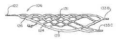
- FIGS. 2 , 3 and 4illustrate in more detail the intravascular self-expanding aneurysm cover device.
- the aneurysm cover deviceis comprised of a headpiece element 122 which extends from the proximal end of a self-expanding skeletal tubular section 124 .
- the tubular section 124is preferably formed from a thin-walled cylindrical tube formed from a super elastic alloy of nickel and titanium, such as nitinol.
- a super elastic alloy of nickel and titaniumsuch as nitinol.
- the tubular section 124is preferably laser cut from a nitinol tube and thereafter treated so as to exhibit super elastic properties at body temperature.
- tubular section 124is formed by removing diamond patterned sections from the sidewalls of the nitinol tube, and when the aneurysm cover device is fully expanded, the diamonds would have angles of between 20 and 70 degrees at their distal and proximal ends. As is apparent, the tubular section 124 may be formed with various other patterns or configurations.
- the proximal end of the tubeis cut to form a loop configuration 125 which extends in a plane which is oblique to the longitudinal axis of the tubular section 124 .
- This angleis preferably between about 10 and 70 degrees to the longitudinal axis of the aneurysm cover device. The preferred angle is 20 degrees to the longitudinal axis.
- After the diamond patterned sections are cutthere is formed a continuous proximal oval shaped loop 126 .
- the headpiece element 122is connected to the most proximal edge of the proximal oval shaped loop 126 .
- the headpiece element 122is retained by the deployment catheter 104 .
- FIGS. 2 through 4illustrate the aneurysm cover device in its normal or expanded state prior to insertion into a delivery catheter for insertion into a vessel of the body.
- the patternis constructed such that the diamonds which are in the lower portion of this Figure, i.e., diamonds on opposite side of aneurysm cover device from the portion of the aneurysm cover device which covers the aneurysm, are larger in size than the diamonds in the upper portion of this Figure which results in a denser mesh existing in the portion of the aneurysm cover device which covers the aneurysm.
- the aneurysm cover deviceincludes outer struts 129 which are cut of a wider thickness than the inner struts 131 which causes the outer structure of the aneurysm cover device to provide a more rigid structure for holding the aneurysm cover device into the vessel and across the aneurysm.
- the rigid outer struts 129also provide additional rigidity to improve “pushability” of the aneurysm cover device through the delivery catheter 128 .
- the aneurysm cover deviceincludes four radiopaque markers 133 a , 133 b , 133 c and 133 d which aide in the positioning of the aneurysm cover device across an aneurysm.
- the radiopaque markers 133 a through 133 dare preferably formed by electroplating the distal portions of the struts with a radiopaque material, such as gold.
- the radiopaque markers 133 d and 133 cdo not extend distally as far as marker 133 a and 133 d .
- the longer markers 133 a and 133 bprovide an indication of the more dense (upper portion of FIG.
- the longer markers 133 a and 133 bassist in placing the more dense portion of the aneurysm cover device at a position across the aneurysm and also provide an indication of the width of the more dense portion of the aneurysm cover device relative to the aneurysm.
- aneurysm cover devicemay be delivered using various types of delivery systems other than the hydraulic delivery system disclosed in the present patent application.
- Such other devicesmay use heat, electric or mechanical systems to release the aneurysm cover device into a vessel with or without other embolic devices, such as embolic coils.
- the aneurysm cover devicemay be treated by applying a coating to reduce the occurrence of a stenosis or to improve compatibility with other embolic devices.
- a coating to reduce the occurrence of a stenosisis rapamycine.
- U.S. Pat. Nos. 5,288,711; 5,516,781; 5,563,146; 5,646,160 and 5,665,728all disclose techniques for applying this coating to medical devices. The disclosures of these patents are incorporated by reference herein.
- the aneurysm cover devicemay be covered by a fabric covering, such as a polymer mesh, to more completely seal the opening of an aneurysm.
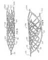
- the self-expanding aneurysm cover deviceis placed within a delivery catheter 128 which serves to compress the aneurysm cover device to a size sufficiently small so that it may be inserted into a vessel and across an aneurysm.
- a delivery catheter 128which serves to compress the aneurysm cover device to a size sufficiently small so that it may be inserted into a vessel and across an aneurysm.
- the proximal loop portion 125 of the tubular section 124is caused to move into a plane which extends closer to parallel to the longitudinal axis of the tubular section 124 .
- the deployment catheter 104may be moved distally relative to the delivery catheter, or alternatively the delivery catheter 128 may be moved proximally relative to the deployment catheter 104 , thereby causing the aneurysm cover device to move out of the distal end of the delivery catheter and thereafter expand into contact with the walls of the vessel and across the neck of the aneurysm.
- the hydraulic deployment systemmay be actuated to release the aneurysm cover device.
- the deployment catheter 104may be withdrawn proximally relative to the delivery catheter to thereby withdraw the aneurysm cover device back into the delivery catheter.
- aneurysm cover deviceAs the aneurysm cover device is withdrawn into the catheter it collapses to fit within the distal portion of the delivery catheter 128 . After the aneurysm cover device is withdrawn back into the delivery catheter 128 , the delivery catheter may be moved into a new position and the aneurysm cover device may once again be deployed.
- the devicecollapses easily as the device is withdrawn back to the delivery catheter 128 . If this edge, or loop 126 , were to be positioned at right angles to the longitudinal axis of the aneurysm cover device, as is the case with prior art devices, it would be very difficult, if not impossible, to withdraw the device back into the delivery catheter 128 once the device had been moved entirely out of the distal end of the catheter.
- the “ramp” configuration at the proximal edge of the aneurysm cover device 106 of the present inventioncauses the aneurysm cover device to collapse easily within the delivery catheter 128 thereby providing a device which may be very easily repositioned after initially being placed at a selected location.
Landscapes
- Health & Medical Sciences (AREA)
- Life Sciences & Earth Sciences (AREA)
- Surgery (AREA)
- Engineering & Computer Science (AREA)
- Biomedical Technology (AREA)
- Animal Behavior & Ethology (AREA)
- Veterinary Medicine (AREA)
- Vascular Medicine (AREA)
- Public Health (AREA)
- Heart & Thoracic Surgery (AREA)
- General Health & Medical Sciences (AREA)
- Molecular Biology (AREA)
- Medical Informatics (AREA)
- Nuclear Medicine, Radiotherapy & Molecular Imaging (AREA)
- Reproductive Health (AREA)
- Neurosurgery (AREA)
- Physics & Mathematics (AREA)
- Optics & Photonics (AREA)
- Cardiology (AREA)
- Oral & Maxillofacial Surgery (AREA)
- Transplantation (AREA)
- Surgical Instruments (AREA)
Abstract
Description
Claims (5)
Priority Applications (1)
| Application Number | Priority Date | Filing Date | Title |
|---|---|---|---|
| US11/903,463US8540763B2 (en) | 2003-06-27 | 2007-09-21 | Detachable self-expanding aneurysm cover device |
Applications Claiming Priority (2)
| Application Number | Priority Date | Filing Date | Title |
|---|---|---|---|
| US10/465,975US20040068314A1 (en) | 2002-01-16 | 2002-01-16 | Detachable self -expanding aneurysm cover device |
| US11/903,463US8540763B2 (en) | 2003-06-27 | 2007-09-21 | Detachable self-expanding aneurysm cover device |
Related Parent Applications (1)
| Application Number | Title | Priority Date | Filing Date |
|---|---|---|---|
| US10/465,975Continuation-In-PartUS20040068314A1 (en) | 2002-01-16 | 2002-01-16 | Detachable self -expanding aneurysm cover device |
Publications (2)
| Publication Number | Publication Date |
|---|---|
| US20080039930A1 US20080039930A1 (en) | 2008-02-14 |
| US8540763B2true US8540763B2 (en) | 2013-09-24 |
Family
ID=32043514
Family Applications (2)
| Application Number | Title | Priority Date | Filing Date |
|---|---|---|---|
| US10/465,975AbandonedUS20040068314A1 (en) | 2002-01-16 | 2002-01-16 | Detachable self -expanding aneurysm cover device |
| US11/903,463Active2026-02-27US8540763B2 (en) | 2003-06-27 | 2007-09-21 | Detachable self-expanding aneurysm cover device |
Family Applications Before (1)
| Application Number | Title | Priority Date | Filing Date |
|---|---|---|---|
| US10/465,975AbandonedUS20040068314A1 (en) | 2002-01-16 | 2002-01-16 | Detachable self -expanding aneurysm cover device |
Country Status (1)
| Country | Link |
|---|---|
| US (2) | US20040068314A1 (en) |
Cited By (9)
| Publication number | Priority date | Publication date | Assignee | Title |
|---|---|---|---|---|
| US20120245671A1 (en)* | 2011-03-25 | 2012-09-27 | Tyco Healthcare Group Lp | Vascular stent with improved vessel wall apposition |
| US9254205B2 (en) | 2012-09-27 | 2016-02-09 | Covidien Lp | Vascular stent with improved vessel wall apposition |
| US9510835B2 (en) | 2005-10-19 | 2016-12-06 | Pulsar Vascular, Inc. | Methods and systems for endovascularly clipping and repairing lumen and tissue defects |
| US9615831B2 (en) | 2008-09-05 | 2017-04-11 | Pulsar Vascular, Inc. | Systems and methods for supporting or occluding a physiological opening or cavity |
| US9636117B2 (en) | 2011-10-05 | 2017-05-02 | Pulsar Vascular, Inc. | Devices, systems and methods for enclosing an anatomical opening |
| US10004510B2 (en) | 2011-06-03 | 2018-06-26 | Pulsar Vascular, Inc. | Systems and methods for enclosing an anatomical opening, including shock absorbing aneurysm devices |
| US10076399B2 (en) | 2013-09-13 | 2018-09-18 | Covidien Lp | Endovascular device engagement |
| US10335153B2 (en) | 2009-09-04 | 2019-07-02 | Pulsar Vascular, Inc. | Systems and methods for enclosing an anatomical opening |
| US10624647B2 (en) | 2011-06-03 | 2020-04-21 | Pulsar Vascular, Inc. | Aneurysm devices with additional anchoring mechanisms and associated systems and methods |
Families Citing this family (60)
| Publication number | Priority date | Publication date | Assignee | Title |
|---|---|---|---|---|
| US6673106B2 (en)* | 2001-06-14 | 2004-01-06 | Cordis Neurovascular, Inc. | Intravascular stent device |
| US7195648B2 (en)* | 2002-05-16 | 2007-03-27 | Cordis Neurovascular, Inc. | Intravascular stent device |
| DE10233085B4 (en) | 2002-07-19 | 2014-02-20 | Dendron Gmbh | Stent with guide wire |
| US8425549B2 (en) | 2002-07-23 | 2013-04-23 | Reverse Medical Corporation | Systems and methods for removing obstructive matter from body lumens and treating vascular defects |
| BRPI0410324A (en) | 2003-05-15 | 2006-05-23 | Biomerix Corp | implantable device, elastomeric matrix production lyophilization processes having a cross-linked structure, polymerization for cross-linked elastomeric matrix preparation and cross-linked composite elastomeric implant preparation, and method for treating an orthopedic disorder |
| US7763077B2 (en) | 2003-12-24 | 2010-07-27 | Biomerix Corporation | Repair of spinal annular defects and annulo-nucleoplasty regeneration |
| US8623067B2 (en) | 2004-05-25 | 2014-01-07 | Covidien Lp | Methods and apparatus for luminal stenting |
| CA2565106C (en)* | 2004-05-25 | 2013-11-05 | Chestnut Medical Technologies, Inc. | Flexible vascular occluding device |
| US20060206200A1 (en)* | 2004-05-25 | 2006-09-14 | Chestnut Medical Technologies, Inc. | Flexible vascular occluding device |
| CA2758946C (en) | 2004-05-25 | 2014-10-21 | Tyco Healthcare Group Lp | Vascular stenting for aneurysms |
| US8617234B2 (en)* | 2004-05-25 | 2013-12-31 | Covidien Lp | Flexible vascular occluding device |
| WO2006044632A2 (en) | 2004-10-15 | 2006-04-27 | Cordis Neurovascular, Inc. | Remodeling device for aneurysms |
| US8043323B2 (en) | 2006-10-18 | 2011-10-25 | Inspiremd Ltd. | In vivo filter assembly |
| US8961586B2 (en)* | 2005-05-24 | 2015-02-24 | Inspiremd Ltd. | Bifurcated stent assemblies |
| CA2609687C (en) | 2005-05-24 | 2014-04-22 | Inspire M.D Ltd. | Stent apparatuses for treatment via body lumens and methods of use |
| US8545530B2 (en)* | 2005-10-19 | 2013-10-01 | Pulsar Vascular, Inc. | Implantable aneurysm closure systems and methods |
| US8152833B2 (en) | 2006-02-22 | 2012-04-10 | Tyco Healthcare Group Lp | Embolic protection systems having radiopaque filter mesh |
| AU2007309715A1 (en)* | 2006-03-24 | 2008-05-02 | Biomerix Corp | Self-expandable endovascular device for aneurysm occlusion |
| WO2008047369A2 (en) | 2006-10-18 | 2008-04-24 | Inspiremd Ltd. | Knitted stent jackets |
| EP3292837B1 (en) | 2006-11-22 | 2022-11-09 | Inspire M.D Ltd | Optimized stent jacket |
| US8439859B2 (en) | 2007-10-08 | 2013-05-14 | Ais Gmbh Aachen Innovative Solutions | Catheter device |
| US9220522B2 (en)* | 2007-10-17 | 2015-12-29 | Covidien Lp | Embolus removal systems with baskets |
| US20100256600A1 (en)* | 2009-04-04 | 2010-10-07 | Ferrera David A | Neurovascular otw pta balloon catheter and delivery system |
| US11337714B2 (en) | 2007-10-17 | 2022-05-24 | Covidien Lp | Restoring blood flow and clot removal during acute ischemic stroke |
| US8088140B2 (en) | 2008-05-19 | 2012-01-03 | Mindframe, Inc. | Blood flow restorative and embolus removal methods |
| US20100174309A1 (en)* | 2008-05-19 | 2010-07-08 | Mindframe, Inc. | Recanalization/revascularization and embolus addressing systems including expandable tip neuro-microcatheter |
| US9198687B2 (en) | 2007-10-17 | 2015-12-01 | Covidien Lp | Acute stroke revascularization/recanalization systems processes and products thereby |
| US8066757B2 (en) | 2007-10-17 | 2011-11-29 | Mindframe, Inc. | Blood flow restoration and thrombus management methods |
| US10123803B2 (en) | 2007-10-17 | 2018-11-13 | Covidien Lp | Methods of managing neurovascular obstructions |
| US8926680B2 (en)* | 2007-11-12 | 2015-01-06 | Covidien Lp | Aneurysm neck bridging processes with revascularization systems methods and products thereby |
| US8585713B2 (en) | 2007-10-17 | 2013-11-19 | Covidien Lp | Expandable tip assembly for thrombus management |
| US20090192455A1 (en)* | 2008-01-07 | 2009-07-30 | David Ferrera | Novel enhanced ptna rapid exchange type of catheter system |
| JP5457373B2 (en) | 2008-02-22 | 2014-04-02 | コヴィディエン リミテッド パートナーシップ | Device for blood flow recovery |
| CN101977650A (en)* | 2008-04-11 | 2011-02-16 | 曼德弗雷姆公司 | Monorail neural microcatheter for delivery of medical device for treatment of stroke, methods and products thereof |
| US20110009941A1 (en)* | 2009-07-08 | 2011-01-13 | Concentric Medical, Inc. | Vascular and bodily duct treatment devices and methods |
| US8357179B2 (en)* | 2009-07-08 | 2013-01-22 | Concentric Medical, Inc. | Vascular and bodily duct treatment devices and methods |
| US8795317B2 (en)* | 2009-07-08 | 2014-08-05 | Concentric Medical, Inc. | Embolic obstruction retrieval devices and methods |
| US8357178B2 (en)* | 2009-07-08 | 2013-01-22 | Concentric Medical, Inc. | Vascular and bodily duct treatment devices and methods |
| US8529596B2 (en) | 2009-07-08 | 2013-09-10 | Concentric Medical, Inc. | Vascular and bodily duct treatment devices and methods |
| US8795345B2 (en)* | 2009-07-08 | 2014-08-05 | Concentric Medical, Inc. | Vascular and bodily duct treatment devices and methods |
| CN102068331B (en)* | 2010-04-20 | 2013-08-07 | 上海微创医疗器械(集团)有限公司 | Bifurcate blood vessel stent |
| US9241816B2 (en) | 2010-04-20 | 2016-01-26 | Shanghai Microport Medical (Group) Co., Ltd. | Stent for bifurcated vessel |
| WO2012106657A2 (en)* | 2011-02-04 | 2012-08-09 | Concentric Medical, Inc. | Vascular and bodily duct treatment devices and methods |
| US8968354B2 (en)* | 2011-10-26 | 2015-03-03 | Boston Scientific Scimed, Inc. | Extended protection embolic filter |
| EP2846706A1 (en) | 2012-05-10 | 2015-03-18 | Pulsar Vascular, Inc. | Coil-tipped aneurysm devices |
| DE102012010687B4 (en)* | 2012-05-30 | 2021-08-19 | ADMEDES GmbH | A method for producing a body implant, an assembly comprising a guide wire and a body implant, and a medical instrument |
| US9301831B2 (en) | 2012-10-30 | 2016-04-05 | Covidien Lp | Methods for attaining a predetermined porosity of a vascular device |
| US9452070B2 (en) | 2012-10-31 | 2016-09-27 | Covidien Lp | Methods and systems for increasing a density of a region of a vascular device |
| US9943427B2 (en) | 2012-11-06 | 2018-04-17 | Covidien Lp | Shaped occluding devices and methods of using the same |
| US9157174B2 (en) | 2013-02-05 | 2015-10-13 | Covidien Lp | Vascular device for aneurysm treatment and providing blood flow into a perforator vessel |
| US9566412B2 (en) | 2014-01-03 | 2017-02-14 | Legacy Ventures LLC | Method of manufacturing a catheter-delivered medical device from a tube |
| WO2015179324A2 (en)* | 2014-05-18 | 2015-11-26 | Legacy Ventures LLC | Clot retrieval system |
| CN108135619B (en)* | 2015-09-25 | 2021-08-13 | 柯惠有限合伙公司 | Medical Device Delivery System |
| US9700332B2 (en)* | 2015-10-23 | 2017-07-11 | Inari Medical, Inc. | Intravascular treatment of vascular occlusion and associated devices, systems, and methods |
| US10342571B2 (en) | 2015-10-23 | 2019-07-09 | Inari Medical, Inc. | Intravascular treatment of vascular occlusion and associated devices, systems, and methods |
| CN105943107A (en)* | 2016-05-26 | 2016-09-21 | 高不郎 | A stent for blocking arterial aneurysm of an initial part of an arterial branch and application thereof |
| FI3528717T3 (en) | 2016-10-24 | 2024-08-09 | Inari Medical Inc | Devices for treating vascular occlusion |
| US10881497B2 (en)* | 2017-01-26 | 2021-01-05 | DePuy Synthes Products, Inc. | Composite vascular flow diverter |
| US11065136B2 (en) | 2018-02-08 | 2021-07-20 | Covidien Lp | Vascular expandable devices |
| US11065009B2 (en) | 2018-02-08 | 2021-07-20 | Covidien Lp | Vascular expandable devices |
Citations (34)
| Publication number | Priority date | Publication date | Assignee | Title |
|---|---|---|---|---|
| US4512338A (en) | 1983-01-25 | 1985-04-23 | Balko Alexander B | Process for restoring patency to body vessels |
| US4994071A (en) | 1989-05-22 | 1991-02-19 | Cordis Corporation | Bifurcating stent apparatus and method |
| US5108407A (en) | 1990-06-08 | 1992-04-28 | Rush-Presbyterian St. Luke's Medical Center | Method and apparatus for placement of an embolic coil |
| US5122136A (en) | 1990-03-13 | 1992-06-16 | The Regents Of The University Of California | Endovascular electrolytically detachable guidewire tip for the electroformation of thrombus in arteries, veins, aneurysms, vascular malformations and arteriovenous fistulas |
| US5147370A (en) | 1991-06-12 | 1992-09-15 | Mcnamara Thomas O | Nitinol stent for hollow body conduits |
| US5176626A (en) | 1992-01-15 | 1993-01-05 | Wilson-Cook Medical, Inc. | Indwelling stent |
| US5197978A (en) | 1991-04-26 | 1993-03-30 | Advanced Coronary Technology, Inc. | Removable heat-recoverable tissue supporting device |
| US5288711A (en) | 1992-04-28 | 1994-02-22 | American Home Products Corporation | Method of treating hyperproliferative vascular disease |
| US5336163A (en) | 1993-01-06 | 1994-08-09 | Smith & Nephew Richards, Inc. | Expandable nasal stent |
| US5354308A (en) | 1992-05-01 | 1994-10-11 | Beth Israel Hospital Association | Metal wire stent |
| US5454788A (en)* | 1991-04-24 | 1995-10-03 | Baxter International Inc. | Exchangeable integrated-wire balloon catheter |
| US5484444A (en) | 1992-10-31 | 1996-01-16 | Schneider (Europe) A.G. | Device for the implantation of self-expanding endoprostheses |
| US5514176A (en) | 1995-01-20 | 1996-05-07 | Vance Products Inc. | Pull apart coil stent |
| US5516781A (en) | 1992-01-09 | 1996-05-14 | American Home Products Corporation | Method of treating restenosis with rapamycin |
| US5551954A (en) | 1991-10-04 | 1996-09-03 | Scimed Life Systems, Inc. | Biodegradable drug delivery vascular stent |
| US5562725A (en) | 1992-09-14 | 1996-10-08 | Meadox Medicals Inc. | Radially self-expanding implantable intraluminal device |
| US5591195A (en) | 1995-10-30 | 1997-01-07 | Taheri; Syde | Apparatus and method for engrafting a blood vessel |
| US5643339A (en) | 1992-08-06 | 1997-07-01 | William Cook Europe A/S | Prosthetic device for sustaining a blood-vessel or hollow organ lumen |
| US5643309A (en) | 1993-03-25 | 1997-07-01 | Myler; Richard | Cardiovascular stent and retrieval apparatus |
| US5667486A (en) | 1993-04-27 | 1997-09-16 | Ams Medinvent, S.A. | Prostatic stent |
| US5716396A (en) | 1993-09-16 | 1998-02-10 | Cordis Corporation | Endoprosthesis having multiple laser welded junctions method and procedure |
| US5728131A (en) | 1995-06-12 | 1998-03-17 | Endotex Interventional Systems, Inc. | Coupling device and method of use |
| US5772668A (en) | 1992-06-18 | 1998-06-30 | American Biomed, Inc. | Apparatus for placing an endoprosthesis |
| US5800520A (en) | 1995-03-10 | 1998-09-01 | Medtronic, Inc. | Tubular endoluminar prosthesis having oblique ends |
| US5836966A (en) | 1997-05-22 | 1998-11-17 | Scimed Life Systems, Inc. | Variable expansion force stent |
| US5893887A (en) | 1997-10-14 | 1999-04-13 | Iowa-India Investments Company Limited | Stent for positioning at junction of bifurcated blood vessel and method of making |
| US6165195A (en) | 1997-08-13 | 2000-12-26 | Advanced Cardiovascylar Systems, Inc. | Stent and catheter assembly and method for treating bifurcations |
| US6254612B1 (en) | 1998-10-22 | 2001-07-03 | Cordis Neurovascular, Inc. | Hydraulic stent deployment system |
| US6267783B1 (en) | 1998-11-09 | 2001-07-31 | Cordis Corporation | Stent which is easily recaptured and repositioned within the body |
| US6344055B1 (en) | 1997-05-14 | 2002-02-05 | Novo Rps Ulc | Method for production of an expandable stent |
| US6413272B1 (en)* | 1997-03-31 | 2002-07-02 | Kabushikikaisha Igaki Iryo Sekkei | Stent for vessel |
| US6468301B1 (en)* | 2000-03-27 | 2002-10-22 | Aga Medical Corporation | Repositionable and recapturable vascular stent/graft |
| US6569190B2 (en)* | 2000-10-11 | 2003-05-27 | Micro Therapeutics, Inc. | Methods for treating aneurysms |
| US6936058B2 (en) | 2000-10-18 | 2005-08-30 | Nmt Medical, Inc. | Over-the-wire interlock attachment/detachment mechanism |
- 2002
- 2002-01-16USUS10/465,975patent/US20040068314A1/ennot_activeAbandoned
- 2007
- 2007-09-21USUS11/903,463patent/US8540763B2/enactiveActive
Patent Citations (38)
| Publication number | Priority date | Publication date | Assignee | Title |
|---|---|---|---|---|
| US4512338A (en) | 1983-01-25 | 1985-04-23 | Balko Alexander B | Process for restoring patency to body vessels |
| US4994071A (en) | 1989-05-22 | 1991-02-19 | Cordis Corporation | Bifurcating stent apparatus and method |
| US5122136A (en) | 1990-03-13 | 1992-06-16 | The Regents Of The University Of California | Endovascular electrolytically detachable guidewire tip for the electroformation of thrombus in arteries, veins, aneurysms, vascular malformations and arteriovenous fistulas |
| US5108407A (en) | 1990-06-08 | 1992-04-28 | Rush-Presbyterian St. Luke's Medical Center | Method and apparatus for placement of an embolic coil |
| US5454788A (en)* | 1991-04-24 | 1995-10-03 | Baxter International Inc. | Exchangeable integrated-wire balloon catheter |
| US5197978A (en) | 1991-04-26 | 1993-03-30 | Advanced Coronary Technology, Inc. | Removable heat-recoverable tissue supporting device |
| US5197978B1 (en) | 1991-04-26 | 1996-05-28 | Advanced Coronary Tech | Removable heat-recoverable tissue supporting device |
| US5147370A (en) | 1991-06-12 | 1992-09-15 | Mcnamara Thomas O | Nitinol stent for hollow body conduits |
| US5551954A (en) | 1991-10-04 | 1996-09-03 | Scimed Life Systems, Inc. | Biodegradable drug delivery vascular stent |
| US5646160A (en) | 1992-01-09 | 1997-07-08 | American Home Products Corporation | Method of treating hyperproliferative vascular disease with rapamycin and mycophenolic acid |
| US5563146A (en) | 1992-01-09 | 1996-10-08 | American Home Products Corporation | Method of treating hyperproliferative vascular disease |
| US5665728A (en) | 1992-01-09 | 1997-09-09 | American Home Products Corporation | Method of treating hyperproliferative vascular disease |
| US5516781A (en) | 1992-01-09 | 1996-05-14 | American Home Products Corporation | Method of treating restenosis with rapamycin |
| US5176626A (en) | 1992-01-15 | 1993-01-05 | Wilson-Cook Medical, Inc. | Indwelling stent |
| US5288711A (en) | 1992-04-28 | 1994-02-22 | American Home Products Corporation | Method of treating hyperproliferative vascular disease |
| US5354308A (en) | 1992-05-01 | 1994-10-11 | Beth Israel Hospital Association | Metal wire stent |
| US5772668A (en) | 1992-06-18 | 1998-06-30 | American Biomed, Inc. | Apparatus for placing an endoprosthesis |
| US5643339A (en) | 1992-08-06 | 1997-07-01 | William Cook Europe A/S | Prosthetic device for sustaining a blood-vessel or hollow organ lumen |
| US5562725A (en) | 1992-09-14 | 1996-10-08 | Meadox Medicals Inc. | Radially self-expanding implantable intraluminal device |
| US5484444A (en) | 1992-10-31 | 1996-01-16 | Schneider (Europe) A.G. | Device for the implantation of self-expanding endoprostheses |
| US5336163A (en) | 1993-01-06 | 1994-08-09 | Smith & Nephew Richards, Inc. | Expandable nasal stent |
| US5643309A (en) | 1993-03-25 | 1997-07-01 | Myler; Richard | Cardiovascular stent and retrieval apparatus |
| US5667486A (en) | 1993-04-27 | 1997-09-16 | Ams Medinvent, S.A. | Prostatic stent |
| US5716396A (en) | 1993-09-16 | 1998-02-10 | Cordis Corporation | Endoprosthesis having multiple laser welded junctions method and procedure |
| US5514176A (en) | 1995-01-20 | 1996-05-07 | Vance Products Inc. | Pull apart coil stent |
| US5800520A (en) | 1995-03-10 | 1998-09-01 | Medtronic, Inc. | Tubular endoluminar prosthesis having oblique ends |
| US5728131A (en) | 1995-06-12 | 1998-03-17 | Endotex Interventional Systems, Inc. | Coupling device and method of use |
| US5591195A (en) | 1995-10-30 | 1997-01-07 | Taheri; Syde | Apparatus and method for engrafting a blood vessel |
| US6413272B1 (en)* | 1997-03-31 | 2002-07-02 | Kabushikikaisha Igaki Iryo Sekkei | Stent for vessel |
| US6344055B1 (en) | 1997-05-14 | 2002-02-05 | Novo Rps Ulc | Method for production of an expandable stent |
| US5836966A (en) | 1997-05-22 | 1998-11-17 | Scimed Life Systems, Inc. | Variable expansion force stent |
| US6165195A (en) | 1997-08-13 | 2000-12-26 | Advanced Cardiovascylar Systems, Inc. | Stent and catheter assembly and method for treating bifurcations |
| US5893887A (en) | 1997-10-14 | 1999-04-13 | Iowa-India Investments Company Limited | Stent for positioning at junction of bifurcated blood vessel and method of making |
| US6254612B1 (en) | 1998-10-22 | 2001-07-03 | Cordis Neurovascular, Inc. | Hydraulic stent deployment system |
| US6267783B1 (en) | 1998-11-09 | 2001-07-31 | Cordis Corporation | Stent which is easily recaptured and repositioned within the body |
| US6468301B1 (en)* | 2000-03-27 | 2002-10-22 | Aga Medical Corporation | Repositionable and recapturable vascular stent/graft |
| US6569190B2 (en)* | 2000-10-11 | 2003-05-27 | Micro Therapeutics, Inc. | Methods for treating aneurysms |
| US6936058B2 (en) | 2000-10-18 | 2005-08-30 | Nmt Medical, Inc. | Over-the-wire interlock attachment/detachment mechanism |
Cited By (20)
| Publication number | Priority date | Publication date | Assignee | Title |
|---|---|---|---|---|
| US9510835B2 (en) | 2005-10-19 | 2016-12-06 | Pulsar Vascular, Inc. | Methods and systems for endovascularly clipping and repairing lumen and tissue defects |
| US10499927B2 (en) | 2005-10-19 | 2019-12-10 | Pulsar Vascular, Inc. | Methods and systems for endovascularly clipping and repairing lumen and tissue defects |
| US11185333B2 (en) | 2008-09-05 | 2021-11-30 | Pulsar Vascular, Inc. | Systems and methods for supporting or occluding a physiological opening or cavity |
| US10285709B2 (en) | 2008-09-05 | 2019-05-14 | Pulsar Vascular, Inc. | Systems and methods for supporting or occluding a physiological opening or cavity |
| US9615831B2 (en) | 2008-09-05 | 2017-04-11 | Pulsar Vascular, Inc. | Systems and methods for supporting or occluding a physiological opening or cavity |
| US11633189B2 (en) | 2009-09-04 | 2023-04-25 | Pulsar Vascular, Inc. | Systems and methods for enclosing an anatomical opening |
| US10335153B2 (en) | 2009-09-04 | 2019-07-02 | Pulsar Vascular, Inc. | Systems and methods for enclosing an anatomical opening |
| US20120245671A1 (en)* | 2011-03-25 | 2012-09-27 | Tyco Healthcare Group Lp | Vascular stent with improved vessel wall apposition |
| US9750623B2 (en) | 2011-03-25 | 2017-09-05 | Covidien Lp | Vascular stent with improved vessel wall apposition |
| US9028540B2 (en)* | 2011-03-25 | 2015-05-12 | Covidien Lp | Vascular stent with improved vessel wall apposition |
| US10004510B2 (en) | 2011-06-03 | 2018-06-26 | Pulsar Vascular, Inc. | Systems and methods for enclosing an anatomical opening, including shock absorbing aneurysm devices |
| US10624647B2 (en) | 2011-06-03 | 2020-04-21 | Pulsar Vascular, Inc. | Aneurysm devices with additional anchoring mechanisms and associated systems and methods |
| US11344311B2 (en) | 2011-06-03 | 2022-05-31 | Pulsar Vascular, Inc. | Aneurysm devices with additional anchoring mechanisms and associated systems and methods |
| US10426487B2 (en) | 2011-10-05 | 2019-10-01 | Pulsar Vascular, Inc. | Devices, systems and methods for enclosing an anatomical opening |
| US11457923B2 (en) | 2011-10-05 | 2022-10-04 | Pulsar Vascular, Inc. | Devices, systems and methods for enclosing an anatomical opening |
| US9636117B2 (en) | 2011-10-05 | 2017-05-02 | Pulsar Vascular, Inc. | Devices, systems and methods for enclosing an anatomical opening |
| US10271978B2 (en) | 2012-09-27 | 2019-04-30 | Covidien Lp | Releasable vascular device connection |
| US9254205B2 (en) | 2012-09-27 | 2016-02-09 | Covidien Lp | Vascular stent with improved vessel wall apposition |
| US10076399B2 (en) | 2013-09-13 | 2018-09-18 | Covidien Lp | Endovascular device engagement |
| US11304712B2 (en) | 2013-09-13 | 2022-04-19 | Covidien Lp | Endovascular device engagement |
Also Published As
| Publication number | Publication date |
|---|---|
| US20080039930A1 (en) | 2008-02-14 |
| US20040068314A1 (en) | 2004-04-08 |
Similar Documents
| Publication | Publication Date | Title |
|---|---|---|
| US8540763B2 (en) | Detachable self-expanding aneurysm cover device | |
| EP1351626B1 (en) | Detachable self-expanding aneurysm cover device | |
| US6254612B1 (en) | Hydraulic stent deployment system | |
| US6554849B1 (en) | Intravascular embolization device | |
| JP7374587B2 (en) | Aneurysm devices and delivery systems | |
| EP1339358B1 (en) | Stent devices with detachable distal and proximal wires | |
| US6613074B1 (en) | Endovascular aneurysm embolization device | |
| US7309351B2 (en) | Expandable stent with markers and stent delivery system | |
| US7201769B2 (en) | Expandable stent and delivery system | |
| JP4472525B2 (en) | Embolizer for vascular lesions | |
| JP2019126734A5 (en) | ||
| EP3622901A1 (en) | Aneurysm occlusion device | |
| EP1621148A1 (en) | Embolic device deployment system with filament release | |
| CN113598860A (en) | Double-layer braided fabric | |
| KR20110095479A (en) | Stent delivery device using microcatheter |
Legal Events
| Date | Code | Title | Description |
|---|---|---|---|
| AS | Assignment | Owner name:CODMAN & SHURTLEFF, INC., MASSACHUSETTS Free format text:MERGER;ASSIGNOR:CORDIS NEUROVASCULAR, INC.;REEL/FRAME:023032/0233 Effective date:20081216 Owner name:CODMAN & SHURTLEFF, INC.,MASSACHUSETTS Free format text:MERGER;ASSIGNOR:CORDIS NEUROVASCULAR, INC.;REEL/FRAME:023032/0233 Effective date:20081216 | |
| AS | Assignment | Owner name:HAND INNOVATIONS LLC, FLORIDA Free format text:ASSIGNMENT OF ASSIGNORS INTEREST;ASSIGNOR:DEPUY SPINE, LLC;REEL/FRAME:030341/0713 Effective date:20121230 Owner name:DEPUY SPINE, INC., MASSACHUSETTS Free format text:ASSIGNMENT OF ASSIGNORS INTEREST;ASSIGNOR:CODMAN & SHURTLEFF, INC.;REEL/FRAME:030341/0689 Effective date:20121230 Owner name:DEPUY SYNTHES PRODUCTS, LLC, MASSACHUSETTS Free format text:CHANGE OF NAME;ASSIGNOR:HAND INNOVATIONS LLC;REEL/FRAME:030341/0721 Effective date:20121231 | |
| STCF | Information on status: patent grant | Free format text:PATENTED CASE | |
| AS | Assignment | Owner name:DEPUY SPINE, LLC, MASSACHUSETTS Free format text:CORRECTIVE ASSIGNMENT TO CORRECT THE ASSIGNEE'S NAME PREVIOUSLY RECORDED AT REEL: 030341 FRAME: 0689. ASSIGNOR(S) HEREBY CONFIRMS THE ASSIGNMENT;ASSIGNOR:CODMAN & SHURTLEFF, INC.;REEL/FRAME:033684/0122 Effective date:20121230 | |
| FPAY | Fee payment | Year of fee payment:4 | |
| MAFP | Maintenance fee payment | Free format text:PAYMENT OF MAINTENANCE FEE, 8TH YEAR, LARGE ENTITY (ORIGINAL EVENT CODE: M1552); ENTITY STATUS OF PATENT OWNER: LARGE ENTITY Year of fee payment:8 | |
| FEPP | Fee payment procedure | Free format text:MAINTENANCE FEE REMINDER MAILED (ORIGINAL EVENT CODE: REM.); ENTITY STATUS OF PATENT OWNER: LARGE ENTITY |